WO2013153808A1 - Image decoding method and image decoding device - Google Patents
Image decoding method and image decoding device Download PDFInfo
- Publication number
- WO2013153808A1 WO2013153808A1 PCT/JP2013/002443 JP2013002443W WO2013153808A1 WO 2013153808 A1 WO2013153808 A1 WO 2013153808A1 JP 2013002443 W JP2013002443 W JP 2013002443W WO 2013153808 A1 WO2013153808 A1 WO 2013153808A1
- Authority
- WO
- WIPO (PCT)
- Prior art keywords
- layer
- data
- video
- unit
- image
- Prior art date
Links
Images


Classifications
-
- H—ELECTRICITY
- H04—ELECTRIC COMMUNICATION TECHNIQUE
- H04N—PICTORIAL COMMUNICATION, e.g. TELEVISION
- H04N19/00—Methods or arrangements for coding, decoding, compressing or decompressing digital video signals
- H04N19/30—Methods or arrangements for coding, decoding, compressing or decompressing digital video signals using hierarchical techniques, e.g. scalability
-
- H—ELECTRICITY
- H04—ELECTRIC COMMUNICATION TECHNIQUE
- H04N—PICTORIAL COMMUNICATION, e.g. TELEVISION
- H04N19/00—Methods or arrangements for coding, decoding, compressing or decompressing digital video signals
- H04N19/50—Methods or arrangements for coding, decoding, compressing or decompressing digital video signals using predictive coding
- H04N19/597—Methods or arrangements for coding, decoding, compressing or decompressing digital video signals using predictive coding specially adapted for multi-view video sequence encoding
-
- H—ELECTRICITY
- H04—ELECTRIC COMMUNICATION TECHNIQUE
- H04N—PICTORIAL COMMUNICATION, e.g. TELEVISION
- H04N19/00—Methods or arrangements for coding, decoding, compressing or decompressing digital video signals
- H04N19/70—Methods or arrangements for coding, decoding, compressing or decompressing digital video signals characterised by syntax aspects related to video coding, e.g. related to compression standards
Definitions
- the present invention provides an image decoding method capable of efficiently decoding a scalable encoded image.
- FIG. 7 is a diagram illustrating another example of the depth map corresponding to the layer.
- FIG. 8 is a diagram illustrating a specific example of the bind information.
- FIG. 9 is an overall configuration diagram of a content supply system that implements a content distribution service.
- FIG. 10 is an overall configuration diagram of a digital broadcasting system.
- FIG. 11 is a block diagram illustrating a configuration example of a television.
- FIG. 12 is a block diagram illustrating a configuration example of an information reproducing / recording unit that reads and writes information from and on a recording medium that is an optical disk.
- FIG. 13 is a diagram illustrating a structure example of a recording medium that is an optical disk.
- FIG. 14A is a diagram illustrating an example of a mobile phone.
- FIG. 14A is a diagram illustrating an example of a mobile phone.
- FIG. 23 is a block diagram illustrating a configuration example of an integrated circuit that implements the moving picture coding method and the moving picture decoding method according to each embodiment.
- FIG. 24 is a diagram illustrating a configuration for switching the driving frequency.
- FIG. 25 is a diagram illustrating steps for identifying video data and switching between driving frequencies.
- FIG. 26 is a diagram illustrating an example of a look-up table in which video data standards are associated with drive frequencies.
- FIG. 27A is a diagram illustrating an example of a configuration for sharing a module of a signal processing unit.
- FIG. 27B is a diagram illustrating another example of a configuration for sharing a module of a signal processing unit.
- An image decoding method is an image decoding method for decoding a scalable encoded image, the step of acquiring a NAL unit type and a layer identifier included in a header of a NAL unit, and the layer identifier Identifying the layer of the image, and if the NAL unit type is a NAL unit type of a depth map indicating depth information of the image, decoding the depth map included in the NAL unit as a depth map for the layer, Decoding the image.
- the scalable coding may include at least one of the spatial scalable video coding, the multi-view video coding, and the quality scalable video coding.
- a recording medium such as a system, an apparatus, an integrated circuit, a computer program, or a computer-readable CD-ROM, and the system, apparatus, integrated circuit, and computer program. And any combination of recording media.
- FIG. 3 shows a configuration in which DepthMap corresponding to all space layers and view layers (textures) exists. Also, DepthMap can be specified by assigning the same layer_id to the DepthMap as the layer corresponding to the DepthMap.
- the payload of the NAL unit includes a layer subjected to scalable video coding and multi-view video coding
- a value indicating VLC is set in Nal_unit_type
- layer_id corresponding to the layer is set in Reserved_one_5bits. Is set.
- the layer_id of the layer and the layer_id (DepthMap) of the DepthMap are further bound.
- the decoder can specify DepthMap corresponding to the layer specified by layer_id.
- layer_id has the same value as layer_id.
- layer_id does not necessarily have to be bound to layer_id (DepthMap). For example, when there is no DepthMap corresponding to a layer, there is no need for layer_id (DepthMap) bound to layer_id.
- FIG. 5 shows an example of the layer structure shown in FIG. 3 and the corresponding DepthMap binding.
- FIG. 8 shows an example of the layer structure shown in FIG. 7 and the corresponding DepthMap binding.
- description of dependency_id, view_id, and quality_id is omitted.
- the decoder can easily specify the DepthMap that the layer refers to by binding the layer_id that identifies the layer and the depthmap_id that identifies the DepthMap using the upper syntax.
- FIG. 9 is a diagram showing an overall configuration of a content supply system ex100 that realizes a content distribution service.
- a communication service providing area is divided into desired sizes, and base stations ex106, ex107, ex108, ex109, and ex110, which are fixed wireless stations, are installed in each cell.
- This content supply system ex100 includes a computer ex111, a PDA (Personal Digital Assistant) ex112, a camera ex113, a mobile phone ex114, a game machine ex115 via the Internet ex101, the Internet service provider ex102, the telephone network ex104, and the base stations ex106 to ex110. Etc. are connected.
- PDA Personal Digital Assistant
- FIG. 11 is a diagram illustrating a television (receiver) ex300 that uses the video decoding method and the video encoding method described in each of the above embodiments.
- the television ex300 obtains or outputs multiplexed data in which audio data is multiplexed with video data via the antenna ex204 or the cable ex203 that receives the broadcast, and demodulates the received multiplexed data.
- the modulation / demodulation unit ex302 that modulates multiplexed data to be transmitted to the outside, and the demodulated multiplexed data is separated into video data and audio data, or the video data and audio data encoded by the signal processing unit ex306 Is provided with a multiplexing / demultiplexing unit ex303.
- the decoded audio signal and video signal are output from the output unit ex309 to the outside. At the time of output, these signals may be temporarily stored in the buffers ex318, ex319, etc. so that the audio signal and the video signal are reproduced in synchronization. Also, the television ex300 may read multiplexed data from recording media ex215 and ex216 such as a magnetic / optical disk and an SD card, not from broadcasting. Next, a configuration in which the television ex300 encodes an audio signal or a video signal and transmits the signal to the outside or to a recording medium will be described.
- the system control unit ex407 uses various types of information held in the buffer ex404, and generates and adds new information as necessary.
- the modulation recording unit ex402, the reproduction demodulation unit This is realized by recording / reproducing information through the optical head ex401 while operating the ex403 and the servo control unit ex406 in a coordinated manner.
- the system control unit ex407 includes, for example, a microprocessor, and executes these processes by executing a read / write program.
- video and still images included in the moving image file linked to the home page are displayed from the display unit ex358 via the LCD control unit ex359.
- the audio signal processing unit ex354 decodes the audio signal, and the audio is output from the audio output unit ex357.
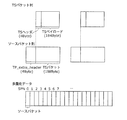
- FIG. 18 shows the format of TS packets that are finally written in the multiplexed data.
- the TS packet is a 188-byte fixed-length packet composed of a 4-byte TS header having information such as a PID for identifying a stream and a 184-byte TS payload for storing data.
- the PES packet is divided and stored in the TS payload.
- a 4-byte TP_Extra_Header is added to a TS packet, forms a 192-byte source packet, and is written in multiplexed data.
- TP_Extra_Header information such as ATS (Arrival_Time_Stamp) is described.
- FIG. 23 shows a configuration of an LSI ex500 that is made into one chip.
- the LSI ex500 includes elements ex501, ex502, ex503, ex504, ex505, ex506, ex507, ex508, and ex509 described below, and each element is connected via a bus ex510.
- the power supply circuit unit ex505 is activated to an operable state by supplying power to each unit when the power supply is on.
- control unit ex501 includes the CPU ex502, the memory controller ex503, the stream controller ex504, the drive frequency control unit ex512, and the like, but the configuration of the control unit ex501 is not limited to this configuration.
- the signal processing unit ex507 may further include a CPU.
- the CPU ex502 may be configured to include a signal processing unit ex507 or, for example, an audio signal processing unit that is a part of the signal processing unit ex507.
- the control unit ex501 is configured to include a signal processing unit ex507 or a CPU ex502 having a part thereof.
- the method for setting the drive frequency is not limited to the configuration in which the drive frequency is lowered.
- the voltage applied to the LSIex500 or the apparatus including the LSIex500 is set high.
- the driving of the CPU ex502 is stopped.
- the decoding processing unit ex902 corresponding to the MPEG4-AVC standard is shared, and for other processing contents specific to one aspect of the present invention that do not correspond to the MPEG4-AVC standard, a dedicated decoding processing unit A configuration using ex901 is conceivable.
- the decoding processing unit for executing the moving picture decoding method described in each of the above embodiments is shared, and the processing content specific to the MPEG4-AVC standard As for, a configuration using a dedicated decoding processing unit may be used.
Abstract
In the present invention, an image decoding method which decodes an image that has been subject to scalable decoding includes steps for: acquiring an NAL unit type and a layer identifier included in a header of an NAL unit; identifying a layer of an image on the basis of the layer identifier; and, if the NAL unit type is an NAL unit type for a depth map indicating depth information for an image, decoding the image by decoding the depth map included in the NAL unit as a depth map related to the layer.
Description
本発明は、スケーラブルビデオ符号化およびマルチビュービデオ符号化された画像の復号方法に関する。
The present invention relates to a method for decoding scalable video encoding and multiview video encoded images.
ISO/IEC 14496-10 Advanced Video Coding(AVC)規格の拡張規格として、マルチビュービデオ符号化(MVC:Multiview Video Coding)規格とスケーラブルビデオ符号化(SVC:Scarable Video Coding)規格が規定されている(例えば、非特許文献1参照)。
The multi-view video coding (MVC) standard and the scalable video coding (SVC: Scalable Video Coding) standard are specified as extensions of the ISO / IEC 14496-10 Advanced Video Coding (AVC) standard. For example, refer nonpatent literature 1).
なお、本明細書では、マルチビュービデオ符号化およびスケーラブルビデオ符号化を総称してスケーラブル符号化と呼ぶ。つまり、スケーラブル符号化は、マルチビュービデオ符号化およびスケーラブルビデオ符号化の少なくとも一方を含む。
In this specification, multi-view video coding and scalable video coding are collectively referred to as scalable coding. That is, the scalable coding includes at least one of multi-view video coding and scalable video coding.
しかしながら、従来技術において、スケーラブル符号化された画像をさらに効率的に復号することが望まれている。
However, in the prior art, it is desired to more efficiently decode a scalable encoded image.
そこで、本発明は、スケーラブル符号化された画像を効率的に復号することができる画像復号方法を提供する。
Therefore, the present invention provides an image decoding method capable of efficiently decoding a scalable encoded image.
本発明の一態様に係る画像復号方法は、スケーラブル符号化された画像を復号する画像復号方法であって、NALユニットのヘッダに含まれるNALユニットタイプおよびレイヤ識別子を取得するステップと、前記レイヤ識別子から前記画像のレイヤを特定するステップと、前記NALユニットタイプが画像の奥行き情報を示すデプスマップのNALユニットタイプである場合、前記NALユニットに含まれるデプスマップを前記レイヤに関するデプスマップとして復号することにより、前記画像を復号するステップと、を含む。
An image decoding method according to an aspect of the present invention is an image decoding method for decoding a scalable encoded image, the step of acquiring a NAL unit type and a layer identifier included in a header of a NAL unit, and the layer identifier Identifying the layer of the image, and when the NAL unit type is a NAL unit type of a depth map indicating depth information of the image, decoding the depth map included in the NAL unit as a depth map related to the layer, thereby Decoding the image.
なお、これらの包括的または具体的な態様は、システム、装置、集積回路、コンピュータプログラムまたはコンピュータ読み取り可能なCD-ROMなどの記録媒体で実現されてもよく、システム、装置、集積回路、コンピュータプログラムおよび記録媒体の任意な組み合わせで実現されてもよい。
Note that these comprehensive or specific modes may be realized by a recording medium such as a system, an apparatus, an integrated circuit, a computer program, or a computer-readable CD-ROM, and the system, apparatus, integrated circuit, and computer program. And any combination of recording media.
本発明の一態様に係る画像復号方法は、スケーラブル符号化された画像を効率的に復号することができる。
The image decoding method according to an aspect of the present invention can efficiently decode a scalable encoded image.
(発明の概要)
本発明の一態様に係る画像復号方法は、スケーラブル符号化された画像を復号する画像復号方法であって、NALユニットのヘッダに含まれるNALユニットタイプおよびレイヤ識別子を取得するステップと、前記レイヤ識別子から前記画像のレイヤを特定するステップと、前記NALユニットタイプが画像の奥行き情報を示すデプスマップのNALユニットタイプである場合、前記NALユニットに含まれるデプスマップを前記レイヤに関するデプスマップとして復号することにより、前記画像を復号するステップと、を含む。 (Summary of Invention)
An image decoding method according to an aspect of the present invention is an image decoding method for decoding a scalable encoded image, the step of acquiring a NAL unit type and a layer identifier included in a header of a NAL unit, and the layer identifier Identifying the layer of the image, and if the NAL unit type is a NAL unit type of a depth map indicating depth information of the image, decoding the depth map included in the NAL unit as a depth map for the layer, Decoding the image.
これによれば、NALユニットのヘッダに含まれるNALユニットタイプを取得することにより、NALユニットにデプスマップが含まれていることを容易に知ることができる。また、NALユニットのヘッダに含まれるレイヤ識別子を取得することにより、NALユニットに含まれるデプスマップがどのレイヤに対するデプスマップであるか容易に特定することができる。したがって、スケーラブル符号化された画像を効率的に復号することが可能となる。
According to this, by acquiring the NAL unit type included in the header of the NAL unit, it can be easily known that the depth map is included in the NAL unit. In addition, by acquiring the layer identifier included in the header of the NAL unit, it is possible to easily identify the layer to which the depth map included in the NAL unit is. Therefore, it is possible to efficiently decode a scalable encoded image.
例えば、前記レイヤは、前記レイヤ識別子と前記レイヤのスケーラブルタイプ識別子とをバインドするためのバインド情報から、前記レイヤの前記スケーラブルタイプ識別子を取得することにより特定されてもよい。
For example, the layer may be specified by acquiring the scalable type identifier of the layer from binding information for binding the layer identifier and the scalable type identifier of the layer.
例えば、前記スケーラブルタイプ識別子は、空間スケーラブルビデオ符号化における空間階層を識別する空間識別子と、マルチビュービデオ符号化におけるビューを識別するビュー識別子と、品質スケーラブルビデオ符号化における品質階層を識別する品質識別子とのうちの少なくとも1つを含んでもよい。
For example, the scalable type identifier includes a spatial identifier that identifies a spatial layer in spatial scalable video coding, a view identifier that identifies a view in multi-view video coding, and a quality identifier that identifies a quality layer in quality scalable video coding And at least one of them.
例えば、前記スケーラブル符号化は、前記空間スケーラブルビデオ符号化、前記マルチビュービデオ符号化、および前記品質スケーラブルビデオ符号化のうちの少なくとも1つを含んでもよい。
For example, the scalable coding may include at least one of the spatial scalable video coding, the multi-view video coding, and the quality scalable video coding.
例えば、前記バインド情報は、シーケンスパラメータセットより上位のシンタックスに含まれてもよい。
For example, the bind information may be included in a syntax higher than the sequence parameter set.
なお、これらの包括的または具体的な態様は、システム、装置、集積回路、コンピュータプログラムまたはコンピュータ読み取り可能なCD-ROMなどの記録媒体で実現されてもよく、システム、装置、集積回路、コンピュータプログラムおよび記録媒体の任意な組み合わせで実現されてもよい。
Note that these comprehensive or specific modes may be realized by a recording medium such as a system, an apparatus, an integrated circuit, a computer program, or a computer-readable CD-ROM, and the system, apparatus, integrated circuit, and computer program. And any combination of recording media.
以下、実施の形態について、図面を参照しながら具体的に説明する。
Hereinafter, embodiments will be specifically described with reference to the drawings.
なお、以下で説明する実施の形態は、いずれも包括的または具体的な例を示すものである。以下の実施の形態で示される数値、形状、材料、構成要素、構成要素の配置位置及び接続形態、ステップ、ステップの順序などは、一例であり、請求の範囲を限定する主旨ではない。また、以下の実施の形態における構成要素のうち、最上位概念を示す独立請求項に記載されていない構成要素については、任意の構成要素として説明される。
It should be noted that each of the embodiments described below shows a comprehensive or specific example. Numerical values, shapes, materials, components, arrangement positions and connection forms of components, steps, order of steps, and the like shown in the following embodiments are merely examples, and are not intended to limit the scope of the claims. In addition, among the constituent elements in the following embodiments, constituent elements that are not described in the independent claims indicating the highest concept are described as optional constituent elements.
(実施の形態1)
図1は、HEVC(High Efficiency Video Coding)規格におけるネットワーク抽象レイヤユニット(NALユニット)の構成を示す。NALユニットは、NALヘッダと、RBSP(Raw Byte Sequence Payload)と、RBSPトレイリングビットとを含む。NALヘッダは、2バイト(16ビット)の固定長であり、NALユニットのタイプを示すNALユニットタイプ(Nal_unit_type(6ビット))を含んでいる。また、NALヘッダには、Reserved_one_5bits(5ビット)が将来の拡張のためにリザーブされている。 (Embodiment 1)
FIG. 1 shows a configuration of a network abstraction layer unit (NAL unit) in the HEVC (High Efficiency Video Coding) standard. The NAL unit includes a NAL header, an RBSP (Raw Byte Sequence Payload), and an RBSP trailing bit. The NAL header has a fixed length of 2 bytes (16 bits) and includes a NAL unit type (Nal_unit_type (6 bits)) indicating the type of the NAL unit. In the NAL header, Reserved_one_5 bits (5 bits) is reserved for future expansion.
図2は、スケーラブルビデオ符号化(SVC)およびマルチビュービデオ符号化(MVC)における符号化対象データのレイヤ構造を示す。SVCには空間SVCが含まれる。図2の例では、符号化対象データは、空間方向に3階層を有しており、各空間階層には空間識別子(dependency_id(0から2))が割り当てられる。この空間識別子は、空間スケーラブルビデオ符号化における空間階層を識別するための情報である。
FIG. 2 shows a layer structure of data to be encoded in scalable video coding (SVC) and multi-view video coding (MVC). The SVC includes a space SVC. In the example of FIG. 2, the encoding target data has three layers in the spatial direction, and a spatial identifier (dependency_id (0 to 2)) is assigned to each spatial layer. This spatial identifier is information for identifying a spatial hierarchy in spatial scalable video coding.
また、図2の例では、符号化対象データは、4つのビュー(view)を有しており、各viewには、ビュー識別子(view_id(0から3))が割り当てられる。このビュー識別子は、マルチビュービデオ符号化におけるビューを識別するための情報である。
Further, in the example of FIG. 2, the encoding target data has four views (views), and a view identifier (view_id (0 to 3)) is assigned to each view. This view identifier is information for identifying a view in multi-view video coding.
なお、SVCには品質SVCも含まれる。図2には図示していないが、各品質階層には、品質識別子(quality_id)が割り当てられる。この品質識別子は、品質スケーラブルビデオ符号化における品質階層を識別するための情報である。
Note that SVC includes quality SVC. Although not shown in FIG. 2, a quality identifier (quality_id) is assigned to each quality layer. This quality identifier is information for identifying a quality layer in quality scalable video coding.
以上のように、スケーラブル符号化(スケーラブルビデオ符号化(SVC)およびマルチビュービデオ符号化(MVC))における各レイヤ(図の矩形)は、dependency_id、view_id、およびquality_idを用いて特定することができる。
As described above, each layer (rectangle in the figure) in scalable coding (scalable video coding (SVC) and multi-view video coding (MVC)) can be identified using dependency_id, view_id, and quality_id. .
しかしながら、ここでは、レイヤの特定をより容易にするために、さらに、各レイヤにレイヤ識別子(layer_id)を割り当てる。図2では、各レイヤにlayer_id(0から11)が割り当てられている。このようにlayer_idを用いることで、デコーダはレイヤをすぐに特定することができる。
However, here, in order to make it easier to specify the layer, a layer identifier (layer_id) is assigned to each layer. In FIG. 2, layer_id (0 to 11) is assigned to each layer. By using layer_id in this way, the decoder can immediately identify the layer.
図3は、図2に示したスケーラブルビデオ符号化(SVC)およびマルチビュービデオ符号化(MVC)における符号化対象データのレイヤ構造に加え、そのレイヤに対応するデプスマップ(DepthMap)を示している。ハッチングされた矩形はレイヤを示し、白色の矩形はそのレイヤに対応するDepthMapを示す。レイヤは、通常のテクスチャ画像であり、ビデオコーディングレイヤ(VCL)のことである。
FIG. 3 shows a depth map (DepthMap) corresponding to the layer in addition to the layer structure of data to be encoded in the scalable video coding (SVC) and multi-view video coding (MVC) shown in FIG. . A hatched rectangle indicates a layer, and a white rectangle indicates DepthMap corresponding to the layer. The layer is a normal texture image and is a video coding layer (VCL).
DepthMapとは、通常の画像の奥行き情報を示すマップのことである。例えば、カメラを用いて撮影した場合、DepthMapとはその撮影した画像に映った物体がカメラの位置からどのくらいの距離にあるかを示している。奥行き情報のレンジは広い。例えば、わずか3メートル離れた被写体もあれば、100メートル離れた背景も考えられる。したがって、DepthMapを決められたビット(例えば8ビット)で表現するために適宜スケーリングがなされる。
DepthMap is a map showing the depth information of a normal image. For example, when photographing using a camera, DepthMap indicates how far the object shown in the photographed image is from the position of the camera. The range of depth information is wide. For example, a subject that is only 3 meters away and a background that is 100 meters away are also conceivable. Accordingly, scaling is appropriately performed in order to express DepthMap with a predetermined bit (for example, 8 bits).
DepthMapの作成の仕方は、いろいろな方法が考えられ、例えば、レンジファインダを用いて距離データを取得することができる。また、コンピュータグラフィック(CG)では、CG画像はもともと3D情報を有しているため、DepthMapの作成は容易である。
There are various methods for creating DepthMap. For example, distance data can be acquired using a range finder. In computer graphics (CG), since a CG image originally has 3D information, it is easy to create DepthMap.
図3では、すべての空間階層およびviewのレイヤ(テクスチャ)にそれぞれ対応するDepthMapが存在する構成となっている。また、DepthMapには、そのDepthMapに対応するレイヤと同じlayer_idを割り当てることによって、DepthMapを特定することができる。
FIG. 3 shows a configuration in which DepthMap corresponding to all space layers and view layers (textures) exists. Also, DepthMap can be specified by assigning the same layer_id to the DepthMap as the layer corresponding to the DepthMap.
なお、図3の例では、すべてのレイヤにそれぞれ対応するDepthMapが存在しているが、これに限定されない。例えば、DepthMapは、ベースレイヤ(dependency_id=0)のみに存在するように構成することができる。
In the example of FIG. 3, DepthMap corresponding to all layers exists, but the present invention is not limited to this. For example, the DepthMap can be configured to exist only in the base layer (dependency_id = 0).
図4Aは、図1に示したNALヘッダに挿入される具体的な値の一例を示す。スケーラブルビデオ符号化(SVC)およびマルチビュービデオ符号化(MVC)が施されたレイヤをペイロード(RBSP)に含むNALユニットの場合、Nal_unit_typeには、VCLのNALユニットタイプが挿入されている。そして、Reserved_one_5bitsには、そのレイヤに対応するlayer_idが挿入される。
FIG. 4A shows an example of specific values inserted in the NAL header shown in FIG. In the case of a NAL unit including a layer subjected to scalable video coding (SVC) and multi-view video coding (MVC) in a payload (RBSP), the NAL unit type of VCL is inserted in Nal_unit_type. Then, layer_id corresponding to the layer is inserted into Reserved_one_5 bits.
つまり、NALユニットのペイロードにスケーラブルビデオ符号化およびマルチビュービデオ符号化が施されたレイヤが含まれる場合、Nal_unit_typeには、VLCを示す値が設定され、Reserved_one_5bitsには、そのレイヤに対応するlayer_idが設定される。
That is, when the payload of the NAL unit includes a layer subjected to scalable video coding and multi-view video coding, a value indicating VLC is set in Nal_unit_type, and layer_id corresponding to the layer is set in Reserved_one_5bits. Is set.
また、DepthMapをペイロードに含むNALユニットの場合、Nal_unit_typeには、DepthMapのNALユニットタイプ(DepthMapを示す値)が挿入される。この結果、デコーダはNALユニットタイプを参照するだけで、ペイロードにはDepthMapが含まれていることを知ることができる。そして、DepthMapのNALヘッダのReserved_one_5bitsには、そのDepthMapに対応するレイヤのlayer_idが挿入される。
Also, in the case of a NAL unit including DepthMap in the payload, the NAL unit type of DepthMap (a value indicating DepthMap) is inserted into Nal_unit_type. As a result, the decoder can know that the DepthMap is included in the payload only by referring to the NAL unit type. Then, layer_id of the layer corresponding to the DepthMap is inserted into Reserved_one_5 bits of the NAL header of DepthMap.
つまり、NALユニットのペイロードにDepthMapが含まれる場合、Nal_unit_typeには、DepthMapを示す値が設定され、Reserved_one_5bitsには、そのDepthMapに対応するレイヤのlayer_idが設定される。
That is, when DepthMap is included in the payload of the NAL unit, a value indicating DepthMap is set in Nal_unit_type, and a layer_id of a layer corresponding to the DepthMap is set in Reserved_one_5bits.
図4Bは、バインド情報を含む上位シンタックスの一例を示す。つまり、図4Bは、上位シンタックスを用いて、layer_idと、dependency_id、view_id、およびquality_idとをバインドするためのバインド情報の一例を示す。例えば、シーケンスパラメータセット(SPS)において、両者のバインドが行われる。デコーダは、NALヘッダのlayer_idを取得した際、SPSのこのバインド情報を参照することにより、そのレイヤの具体的な情報であるスケーラブルタイプ識別子(dependency_id、view_id、quality_id)を知ることができる。
FIG. 4B shows an example of upper syntax including bind information. That is, FIG. 4B shows an example of binding information for binding layer_id to dependency_id, view_id, and quality_id using the upper syntax. For example, in the sequence parameter set (SPS), both are bound. When the decoder acquires layer_id of the NAL header, the decoder can know the scalable type identifier (dependency_id, view_id, quality_id), which is specific information of the layer, by referring to the binding information of the SPS.
なお、layer_idは必ずしもdependency_id、view_id、quality_idのすべての値とバインドされている必要はない。つまり、レイヤ識別子にバインドされるスケーラブルタイプ識別子は、空間識別子(dependency_id)、ビュー識別子(view_id)、および品質識別子(quality_id)のうちの少なくとも1つを含めばよい。例えば、SVCだけが行われ、MVCが行われない場合は、layer_idはview_idとバインドされる必要はない。
Note that layer_id does not necessarily have to be bound to all values of dependency_id, view_id, and quality_id. That is, the scalable type identifier bound to the layer identifier may include at least one of a spatial identifier (dependency_id), a view identifier (view_id), and a quality identifier (quality_id). For example, if only SVC is performed and MVC is not performed, layer_id need not be bound to view_id.
なお、図4BはSPSの一部だけを抽出して記載したものである。SPSには、layer_idの個数分(レイヤの個数分)だけlayer_idのバインドが含まれている。
Note that FIG. 4B shows only a part of the SPS extracted. The SPS includes layer_id bindings by the number of layer_ids (the number of layers).
また、図4Bでは、さらに、レイヤのlayer_idとDepthMapのlayer_id(DepthMap)とがバインドされている。これにより、デコーダは、layer_idで特定されるレイヤに対応するDepthMapを特定することが可能である。図3の例のように、すべてのレイヤにそれぞれ対応するDepthMapが存在している場合には、layer_id(DepthMap)にはlayer_idと同じ値が入る。なお、layer_idは必ずしもlayer_id(DepthMap)とバインドされる必要はない。例えば、レイヤに対応するDepthMapが存在しない場合には、layer_idとバインドされるlayer_id(DepthMap)はなくてもよい。
Further, in FIG. 4B, the layer_id of the layer and the layer_id (DepthMap) of the DepthMap are further bound. Thereby, the decoder can specify DepthMap corresponding to the layer specified by layer_id. As shown in the example of FIG. 3, when DepthMap corresponding to all layers exists, layer_id (DepthMap) has the same value as layer_id. Note that layer_id does not necessarily have to be bound to layer_id (DepthMap). For example, when there is no DepthMap corresponding to a layer, there is no need for layer_id (DepthMap) bound to layer_id.
また、図4Aのようにレイヤと、そのレイヤに対応するDepthMapとが同じlayer_idを用いる場合、図4Bにおいて明示的にバインドする必要はない。SPSには、そのレイヤがDepthMapを有するか否かを示すフラグが含まれていればよく、フラグが真である場合、そのレイヤと、そのレイヤに対応するDepthMapがバインドされていることを示す。
Further, when the layer and the DepthMap corresponding to the layer use the same layer_id as shown in FIG. 4A, it is not necessary to bind explicitly in FIG. 4B. The SPS only needs to include a flag indicating whether or not the layer has DepthMap. When the flag is true, the layer and the DepthMap corresponding to the layer are bound.
図5は、上位シンタックスを用いて、layer_idとdependency_id、view_id、およびquality_idとをバインドし、かつ、layer_idとDepthMapのlayer_id(説明をわかりやすくするためlayer_id(DepthMap)と表記する)とをバインドした場合の具体例を示す。
FIG. 5 uses a higher level syntax to bind layer_id to dependency_id, view_id, and quality_id, and to layer_id and layerMap layer_id (denoted as layer_id (DepthMap) for ease of explanation). A specific example of the case is shown.
上位シンタックスとしてはSPSが用いられているが、これに限定されない。SPSより上位または下位のレイヤでバインドしてもよい。
SPS is used as the upper syntax, but it is not limited to this. You may bind in a layer higher or lower than SPS.
図5は、図3に示したレイヤ構造と、それに対応するDepthMapのバインドの一例を示している。1つ目のバインドでは、layer_id=0とdependency_id=0、view_id=0、およびquality_id=0とがバインドされている。また、layer_id=0とDepthMapのlayer_id(DepthMap)=0とがバインドされている。
FIG. 5 shows an example of the layer structure shown in FIG. 3 and the corresponding DepthMap binding. In the first binding, layer_id = 0, dependency_id = 0, view_id = 0, and quality_id = 0 are bound. Also, layer_id = 0 and depthMap layer_id (DepthMap) = 0 are bound.
そして、2つ目のバインドでは、layer_id=1とdependency_id=1、view_id=0、およびquality_id=0とがバインドされている。また、layer_id=1とDepthMapのlayer_id(DepthMap)=1とがバインドされている。
In the second binding, layer_id = 1, dependency_id = 1, view_id = 0, and quality_id = 0 are bound. Also, layer_id = 1 and depthMap layer_id (DepthMap) = 1 are bound.
SPSには、このようなバインドがレイヤの個数(12個)含まれることになる。
The SPS includes such a binding (the number of layers (12)).
以上のように、NALユニットタイプがデプスマップのNALユニットタイプである場合に、NALユニットに含まれるデプスマップを、レイヤ識別子から特定されたレイヤに関するデプスマップとして復号することにより、スケーラブル符号化された画像を効率的に復号することができる。
As described above, when the NAL unit type is the NAL unit type of the depth map, by decoding the depth map included in the NAL unit as the depth map related to the layer specified from the layer identifier, the scalable encoded image can be obtained. It can be efficiently decoded.
(変形例)
図6Aは、図4Aの変形例である。図4Aでは、Nal_unit_typeがDepthMapのNALユニットタイプの場合、Reserved_one_5bitsには、そのDepthMapに対応するレイヤのlayer_idが挿入される。これに対して、図6Aでは、DepthMapに対応するレイヤのlayer_idとは別に、DepthMapを特定するdepthmap_idが定義され、NALヘッダのReserved_one_5bitsには、そのDepthMapのdepthmap_idが挿入(設定)される。DepthMapをlayer_idから切り離す(layer_idを用いて特定しない)ことにより、より自由度の高いバインドが可能となる。 (Modification)
FIG. 6A is a modification of FIG. 4A. In FIG. 4A, when Nal_unit_type is a NAL unit type of DepthMap, layer_id of the layer corresponding to the DepthMap is inserted into Reserved_one_5 bits. On the other hand, in FIG. 6A, depthmap_id for specifying DepthMap is defined separately from layer_id of the layer corresponding to DepthMap, and depthmap_id of the DepthMap is inserted (set) in Reserved_one_5 bits of the NAL header. By separating DepthMap from layer_id (not specified using layer_id), binding with a higher degree of freedom becomes possible.
図6Bは、図4Aを図6Aのように変形したことにより、図4Bにもそれに伴う修正を加えたものである。図6Bでは、layer_idとバインドされるのはdepthmap_idとなる。これにより、デコーダは、layer_idで特定されるレイヤに対応するDepthMapをdepthmap_idを用いて特定することが可能である。なお、layer_idは必ずしもdepthmap_idとバインドされる必要はない。例えば、レイヤに対応するDepthMapが存在しない場合には、layer_idとバインドされるdepthmap_idはなくてもよい。
FIG. 6B is obtained by modifying FIG. 4A as shown in FIG. In FIG. 6B, what is bound to layer_id is depthmap_id. Thereby, the decoder can specify DepthMap corresponding to the layer specified by layer_id using depthmap_id. Note that layer_id does not necessarily need to be bound to depthmap_id. For example, when there is no DepthMap corresponding to the layer, there is no need for depthmap_id bound to layer_id.
図7は、図3に示したスケーラブルビデオ符号化(SVC)およびマルチビュービデオ符号化(MVC)における符号化対象データのレイヤ構造と、そのレイヤに対応するDepthMapの別な一例である。
FIG. 7 shows another example of the layer structure of data to be encoded in the scalable video coding (SVC) and multi-view video coding (MVC) shown in FIG. 3 and the DepthMap corresponding to that layer.
図3では、すべてのレイヤに対して対応するDepthMapが存在していたが、図7では、一部のレイヤにしかDepthMapは存在しない。各ビューにおいて、1枚、または2枚のDepthMapが存在する。
In FIG. 3, depth maps corresponding to all layers exist, but in FIG. 7, depth maps exist only in some layers. In each view, there is one or two DepthMaps.
また、図7では、DepthMapは、図6Aおよび図6Bで説明したdepthmap_idで特定される。各DepthMapにはdepthmap_id(12から16)が割り当てられている。
Also, in FIG. 7, DepthMap is specified by depthmap_id described in FIGS. 6A and 6B. Depthmap_id (12 to 16) is assigned to each DepthMap.
DepthMapは解像度の違いによる影響が少なく、各ビューで1つの(共通な)DepthMapを使用することができる。例えば、0番目のview(view_id=0)のように、ベースレイヤのみ対応するDepthMapが存在する場合において、解像度の大きい空間上位レイヤでは、そのDepthMap(depthmap_id=12)をスケーリングすることにより使用することが可能である。つまり、layer_id=1のレイヤでは対応するDepthMapが存在しないので、layer_id=0のレイヤに対応するDepthMap(depthmap_id=12)を参照する。ここで、どのDepthMapを参照するかが問題になるが、それについては図8を用いて後述する。
DepthMap is less affected by the difference in resolution, and one (common) DepthMap can be used for each view. For example, when there is a DepthMap corresponding only to the base layer as in the 0th view (view_id = 0), the depth map (depthmap_id = 12) is used by scaling the depth map in a spatial upper layer having a large resolution. Is possible. That is, since there is no corresponding DepthMap in the layer of layer_id = 1, the DepthMap (depthmap_id = 12) corresponding to the layer of layer_id = 0 is referred to. Here, which depth map is referred to becomes a problem, which will be described later with reference to FIG.
図8は、バインド情報を含む上位シンタックスの具体例を示す。つまり、図8では、上位シンタックスを用いて、layer_idとdepthmap_idとをバインドした場合の具体例を示す。上位シンタックスとしてはSPSが用いられているが、これに限定されない。SPSより上位または下位のレイヤでlayer_idとdepthmap_idとをバインドしてもよい。
FIG. 8 shows a specific example of the upper syntax including the binding information. That is, FIG. 8 shows a specific example when the layer_id and the depthmap_id are bound using the upper syntax. SPS is used as the upper syntax, but it is not limited to this. You may bind layer_id and depthmap_id in a layer higher or lower than SPS.
図8は、図7に示したレイヤ構造と、それに対応するDepthMapのバインドの一例を示している。なお、図8では、dependency_id、view_id、およびquality_idについては記載を省略している。
FIG. 8 shows an example of the layer structure shown in FIG. 7 and the corresponding DepthMap binding. In FIG. 8, description of dependency_id, view_id, and quality_id is omitted.
1つ目のバインドでは、layer_id=0とdepthmap_id=12とがバインドされている。そして、2つ目のバインドでは、layer_id=1とdepthmap_id=12とがバインドされている。図7において説明したように、layer_id=1のレイヤでは対応するDepthMapが存在しない。SPSで示されるバインドを参照することにより、layer_id=1のレイヤは、layer_id=0のレイヤに対応するDepthMap(depthmap_id=12)を参照すべきことがわかる。同様にして、layer_id=2のレイヤは、layer_id=0のレイヤに対応するDepthMap(depthmap_id=12)を参照すべきことがわかる。
In the first binding, layer_id = 0 and depthmap_id = 12 are bound. In the second binding, layer_id = 1 and depthmap_id = 12 are bound. As described with reference to FIG. 7, there is no corresponding DepthMap in the layer with layer_id = 1. By referring to the binding indicated by SPS, it is understood that the layer with layer_id = 1 should refer to DepthMap (depthmap_id = 12) corresponding to the layer with layer_id = 0. Similarly, it can be seen that the layer of layer_id = 2 should refer to DepthMap (depthmap_id = 12) corresponding to the layer of layer_id = 0.
また、4番目のビュー(view_id=3)においては、Veiw内に複数枚のDepthMapが存在している。この場合でもlayer_idとdepthmap_idとのバインドを参照することにより、レイヤが参照すべきDepthMapを特定することが可能となる。例えば、layer_id=10のレイヤは、layer_id=9のレイヤに対応するDepthMap(depthmap_id=15)を参照すべきことがわかる。
In the fourth view (view_id = 3), there are multiple DepthMaps in the View. Even in this case, by referring to the binding between layer_id and depthmap_id, it is possible to specify the DepthMap that the layer should refer to. For example, it can be seen that the layer of layer_id = 10 should refer to DepthMap (depthmap_id = 15) corresponding to the layer of layer_id = 9.
以上のように、上位シンタックスを用いて、レイヤを特定するlayer_idと、DepthMapを特定するdepthmap_idとをバインドすることにより、デコーダは、レイヤが参照するDepthMapを容易に特定することができる。
As described above, the decoder can easily specify the DepthMap that the layer refers to by binding the layer_id that identifies the layer and the depthmap_id that identifies the DepthMap using the upper syntax.
以上、本発明の1つまたは複数の態様に係る画像復号方法について、実施の形態に基づいて説明したが、本発明は、この実施の形態に限定されるものではない。本発明の趣旨を逸脱しない限り、当業者が思いつく各種変形を本実施の形態に施したものや、異なる実施の形態における構成要素を組み合わせて構築される形態も、本発明の1つまたは複数の態様の範囲内に含まれてもよい。
The image decoding method according to one or more aspects of the present invention has been described based on the embodiment, but the present invention is not limited to this embodiment. Unless it deviates from the gist of the present invention, one or more of the present invention may be applied to the present embodiment in which various modifications conceived by those skilled in the art have been made in this embodiment, or a combination of components in different embodiments. It may be included within the scope of the embodiments.
なお、上記実施の形態において、各構成要素は、専用のハードウェアで構成されるか、各構成要素に適したソフトウェアプログラムを実行することによって実現されてもよい。各構成要素は、CPUまたはプロセッサなどのプログラム実行部が、ハードディスクまたは半導体メモリなどの記録媒体に記録されたソフトウェアプログラムを読み出して実行することによって実現されてもよい。
In the above embodiment, each component may be configured by dedicated hardware or may be realized by executing a software program suitable for each component. Each component may be realized by a program execution unit such as a CPU or a processor reading and executing a software program recorded on a recording medium such as a hard disk or a semiconductor memory.
言い換えると、画像復号装置は、制御回路(control circuitry)と、当該制御回路に電気的に接続された(当該制御回路からアクセス可能な)記憶装置(storage)とを備えてもよい。制御回路は、専用のハードウェアおよびプログラム実行部の少なくとも一方を含んでもよい。また、記憶装置は、制御回路がプログラム実行部を含む場合には、当該プログラム実行部により実行されるソフトウェアプログラムを記憶してもよい。
In other words, the image decoding apparatus may include a control circuit and a storage device (storage) electrically connected to the control circuit (accessible from the control circuit). The control circuit may include at least one of dedicated hardware and a program execution unit. In addition, when the control circuit includes a program execution unit, the storage device may store a software program executed by the program execution unit.
上記実施の形態の画像復号方法などを実現するソフトウェアは、次のようなプログラムである。すなわち、このプログラムは、制御回路(コンピュータ)に、スケーラブル符号化された画像を復号する画像復号方法であって、NALユニットのヘッダに含まれるNALユニットタイプおよびレイヤ識別子を取得するステップと、前記レイヤ識別子から前記画像のレイヤを特定するステップと、前記NALユニットタイプが画像の奥行き情報を示すデプスマップのNALユニットタイプである場合、前記NALユニットに含まれるデプスマップを前記レイヤに関するデプスマップとして復号することにより、前記画像を復号するステップと、を含む画像復号方法を実行させる。
The software that realizes the image decoding method of the above-described embodiment is the following program. That is, this program is an image decoding method for decoding a scalable encoded image to a control circuit (computer), the NAL unit type and the layer identifier included in the header of the NAL unit being acquired, and the layer identifier Identifying the layer of the image from, and if the NAL unit type is a depth map NAL unit type indicating depth information of the image, decoding the depth map included in the NAL unit as a depth map for the layer, And a step of decoding the image.
(実施の形態2)
上記各実施の形態で示した動画像符号化方法(画像符号化方法)または動画像復号化方法(画像復号方法)の構成を実現するためのプログラムを記憶メディアに記録することにより、上記各実施の形態で示した処理を独立したコンピュータシステムにおいて簡単に実施することが可能となる。記憶メディアは、磁気ディスク、光ディスク、光磁気ディスク、ICカード、半導体メモリ等、プログラムを記録できるものであればよい。 (Embodiment 2)
By recording a program for realizing the configuration of the moving image encoding method (image encoding method) or the moving image decoding method (image decoding method) shown in each of the above embodiments on a storage medium, each of the above embodiments It is possible to easily execute the processing shown in the form in the independent computer system. The storage medium may be any medium that can record a program, such as a magnetic disk, an optical disk, a magneto-optical disk, an IC card, and a semiconductor memory.
さらにここで、上記各実施の形態で示した動画像符号化方法(画像符号化方法)や動画像復号化方法(画像復号方法)の応用例とそれを用いたシステムを説明する。当該システムは、画像符号化方法を用いた画像符号化装置、及び画像復号方法を用いた画像復号装置からなる画像符号化復号装置を有することを特徴とする。システムにおける他の構成について、場合に応じて適切に変更することができる。
Furthermore, application examples of the moving picture coding method (picture coding method) and the moving picture decoding method (picture decoding method) shown in the above embodiments and a system using the same will be described. The system has an image encoding / decoding device including an image encoding device using an image encoding method and an image decoding device using an image decoding method. Other configurations in the system can be appropriately changed according to circumstances.
図9は、コンテンツ配信サービスを実現するコンテンツ供給システムex100の全体構成を示す図である。通信サービスの提供エリアを所望の大きさに分割し、各セル内にそれぞれ固定無線局である基地局ex106、ex107、ex108、ex109、ex110が設置されている。
FIG. 9 is a diagram showing an overall configuration of a content supply system ex100 that realizes a content distribution service. A communication service providing area is divided into desired sizes, and base stations ex106, ex107, ex108, ex109, and ex110, which are fixed wireless stations, are installed in each cell.
このコンテンツ供給システムex100は、インターネットex101にインターネットサービスプロバイダex102および電話網ex104、および基地局ex106からex110を介して、コンピュータex111、PDA(Personal Digital Assistant)ex112、カメラex113、携帯電話ex114、ゲーム機ex115などの各機器が接続される。
This content supply system ex100 includes a computer ex111, a PDA (Personal Digital Assistant) ex112, a camera ex113, a mobile phone ex114, a game machine ex115 via the Internet ex101, the Internet service provider ex102, the telephone network ex104, and the base stations ex106 to ex110. Etc. are connected.
しかし、コンテンツ供給システムex100は図9のような構成に限定されず、いずれかの要素を組合せて接続するようにしてもよい。また、固定無線局である基地局ex106からex110を介さずに、各機器が電話網ex104に直接接続されてもよい。また、各機器が近距離無線等を介して直接相互に接続されていてもよい。
However, the content supply system ex100 is not limited to the configuration shown in FIG. 9, and may be connected by combining any of the elements. In addition, each device may be directly connected to the telephone network ex104 without going from the base station ex106, which is a fixed wireless station, to ex110. In addition, the devices may be directly connected to each other via short-range wireless or the like.
カメラex113はデジタルビデオカメラ等の動画撮影が可能な機器であり、カメラex116はデジタルカメラ等の静止画撮影、動画撮影が可能な機器である。また、携帯電話ex114は、GSM(登録商標)(Global System for Mobile Communications)方式、CDMA(Code Division Multiple Access)方式、W-CDMA(Wideband-Code Division Multiple Access)方式、若しくはLTE(Long Term Evolution)方式、HSPA(High Speed Packet Access)の携帯電話機、またはPHS(Personal Handyphone System)等であり、いずれでも構わない。
The camera ex113 is a device that can shoot moving images such as a digital video camera, and the camera ex116 is a device that can shoot still images and movies such as a digital camera. The mobile phone ex114 is a GSM (registered trademark) (Global System for Mobile Communications) system, a CDMA (Code Division Multiple Access) system, a W-CDMA (Wideband-Code Division Multiple Access) system, or an LTE (Long Terminal Term Evolution). It is possible to use any of the above-mentioned systems, HSPA (High Speed Packet Access) mobile phone, PHS (Personal Handyphone System), or the like.
コンテンツ供給システムex100では、カメラex113等が基地局ex109、電話網ex104を通じてストリーミングサーバex103に接続されることで、ライブ配信等が可能になる。ライブ配信では、ユーザがカメラex113を用いて撮影するコンテンツ(例えば、音楽ライブの映像等)に対して上記各実施の形態で説明したように符号化処理を行い(即ち、本発明の一態様に係る画像符号化装置として機能する)、ストリーミングサーバex103に送信する。一方、ストリーミングサーバex103は要求のあったクライアントに対して送信されたコンテンツデータをストリーム配信する。クライアントとしては、上記符号化処理されたデータを復号化することが可能な、コンピュータex111、PDAex112、カメラex113、携帯電話ex114、ゲーム機ex115等がある。配信されたデータを受信した各機器では、受信したデータを復号化処理して再生する(即ち、本発明の一態様に係る画像復号装置として機能する)。
In the content supply system ex100, the camera ex113 and the like are connected to the streaming server ex103 through the base station ex109 and the telephone network ex104, thereby enabling live distribution and the like. In live distribution, content that is shot by a user using the camera ex113 (for example, music live video) is encoded as described in each of the above embodiments (that is, in one aspect of the present invention). Functions as an image encoding device), and transmits it to the streaming server ex103. On the other hand, the streaming server ex103 stream-distributes the content data transmitted to the requested client. Examples of the client include a computer ex111, a PDA ex112, a camera ex113, a mobile phone ex114, and a game machine ex115 that can decode the encoded data. Each device that receives the distributed data decodes the received data and reproduces it (that is, functions as an image decoding device according to one embodiment of the present invention).
なお、撮影したデータの符号化処理はカメラex113で行っても、データの送信処理をするストリーミングサーバex103で行ってもよいし、互いに分担して行ってもよい。同様に配信されたデータの復号化処理はクライアントで行っても、ストリーミングサーバex103で行ってもよいし、互いに分担して行ってもよい。また、カメラex113に限らず、カメラex116で撮影した静止画像および/または動画像データを、コンピュータex111を介してストリーミングサーバex103に送信してもよい。この場合の符号化処理はカメラex116、コンピュータex111、ストリーミングサーバex103のいずれで行ってもよいし、互いに分担して行ってもよい。
Note that the captured data may be encoded by the camera ex113, the streaming server ex103 that performs data transmission processing, or may be shared with each other. Similarly, the decryption processing of the distributed data may be performed by the client, the streaming server ex103, or may be performed in common with each other. In addition to the camera ex113, still images and / or moving image data captured by the camera ex116 may be transmitted to the streaming server ex103 via the computer ex111. The encoding process in this case may be performed by any of the camera ex116, the computer ex111, and the streaming server ex103, or may be performed in a shared manner.
また、これら符号化・復号化処理は、一般的にコンピュータex111や各機器が有するLSIex500において処理する。LSIex500は、ワンチップであっても複数チップからなる構成であってもよい。なお、動画像符号化・復号化用のソフトウェアをコンピュータex111等で読み取り可能な何らかの記録メディア(CD-ROM、フレキシブルディスク、ハードディスクなど)に組み込み、そのソフトウェアを用いて符号化・復号化処理を行ってもよい。さらに、携帯電話ex114がカメラ付きである場合には、そのカメラで取得した動画データを送信してもよい。このときの動画データは携帯電話ex114が有するLSIex500で符号化処理されたデータである。
Further, these encoding / decoding processes are generally performed in the computer ex111 and the LSI ex500 included in each device. The LSI ex500 may be configured as a single chip or a plurality of chips. It should be noted that moving image encoding / decoding software is incorporated into some recording medium (CD-ROM, flexible disk, hard disk, etc.) that can be read by the computer ex111, etc., and encoding / decoding processing is performed using the software. May be. Furthermore, when the mobile phone ex114 is equipped with a camera, moving image data acquired by the camera may be transmitted. The moving image data at this time is data encoded by the LSI ex500 included in the mobile phone ex114.
また、ストリーミングサーバex103は複数のサーバや複数のコンピュータであって、データを分散して処理したり記録したり配信するものであってもよい。
Also, the streaming server ex103 may be a plurality of servers or a plurality of computers, and may process, record, and distribute data in a distributed manner.
以上のようにして、コンテンツ供給システムex100では、符号化されたデータをクライアントが受信して再生することができる。このようにコンテンツ供給システムex100では、ユーザが送信した情報をリアルタイムでクライアントが受信して復号化し、再生することができ、特別な権利や設備を有さないユーザでも個人放送を実現できる。
As described above, in the content supply system ex100, the encoded data can be received and reproduced by the client. Thus, in the content supply system ex100, the information transmitted by the user can be received, decrypted and reproduced by the client in real time, and personal broadcasting can be realized even for a user who does not have special rights or facilities.
なお、コンテンツ供給システムex100の例に限らず、図10に示すように、デジタル放送用システムex200にも、上記各実施の形態の少なくとも動画像符号化装置(画像符号化装置)または動画像復号化装置(画像復号装置)のいずれかを組み込むことができる。具体的には、放送局ex201では映像データに音楽データなどが多重化された多重化データが電波を介して通信または衛星ex202に伝送される。この映像データは上記各実施の形態で説明した動画像符号化方法により符号化されたデータである(即ち、本発明の一態様に係る画像符号化装置によって符号化されたデータである)。これを受けた放送衛星ex202は、放送用の電波を発信し、この電波を衛星放送の受信が可能な家庭のアンテナex204が受信する。受信した多重化データを、テレビ(受信機)ex300またはセットトップボックス(STB)ex217等の装置が復号化して再生する(即ち、本発明の一態様に係る画像復号装置として機能する)。
In addition to the example of the content supply system ex100, as shown in FIG. 10, the digital broadcast system ex200 also includes at least the moving image encoding device (image encoding device) or the moving image decoding according to each of the above embodiments. Any of the devices (image decoding devices) can be incorporated. Specifically, in the broadcast station ex201, multiplexed data obtained by multiplexing music data and the like on video data is transmitted to a communication or satellite ex202 via radio waves. This video data is data encoded by the moving image encoding method described in each of the above embodiments (that is, data encoded by the image encoding apparatus according to one aspect of the present invention). Receiving this, the broadcasting satellite ex202 transmits a radio wave for broadcasting, and this radio wave is received by a home antenna ex204 capable of receiving satellite broadcasting. The received multiplexed data is decoded and reproduced by an apparatus such as the television (receiver) ex300 or the set top box (STB) ex217 (that is, functions as an image decoding apparatus according to one embodiment of the present invention).
また、DVD、BD等の記録メディアex215に記録した多重化データを読み取り復号化する、または記録メディアex215に映像信号を符号化し、さらに場合によっては音楽信号と多重化して書き込むリーダ/レコーダex218にも上記各実施の形態で示した動画像復号化装置または動画像符号化装置を実装することが可能である。この場合、再生された映像信号はモニタex219に表示され、多重化データが記録された記録メディアex215により他の装置やシステムにおいて映像信号を再生することができる。また、ケーブルテレビ用のケーブルex203または衛星/地上波放送のアンテナex204に接続されたセットトップボックスex217内に動画像復号化装置を実装し、これをテレビのモニタex219で表示してもよい。このときセットトップボックスではなく、テレビ内に動画像復号化装置を組み込んでもよい。
Also, a reader / recorder ex218 that reads and decodes multiplexed data recorded on a recording medium ex215 such as a DVD or a BD, or encodes a video signal on the recording medium ex215 and, in some cases, multiplexes and writes it with a music signal. It is possible to mount the moving picture decoding apparatus or moving picture encoding apparatus described in the above embodiments. In this case, the reproduced video signal is displayed on the monitor ex219, and the video signal can be reproduced in another device or system using the recording medium ex215 on which the multiplexed data is recorded. Alternatively, a moving picture decoding apparatus may be mounted in a set-top box ex217 connected to a cable ex203 for cable television or an antenna ex204 for satellite / terrestrial broadcasting and displayed on the monitor ex219 of the television. At this time, the moving picture decoding apparatus may be incorporated in the television instead of the set top box.
図11は、上記各実施の形態で説明した動画像復号化方法および動画像符号化方法を用いたテレビ(受信機)ex300を示す図である。テレビex300は、上記放送を受信するアンテナex204またはケーブルex203等を介して映像データに音声データが多重化された多重化データを取得、または出力するチューナex301と、受信した多重化データを復調する、または外部に送信する多重化データに変調する変調/復調部ex302と、復調した多重化データを映像データと、音声データとに分離する、または信号処理部ex306で符号化された映像データ、音声データを多重化する多重/分離部ex303を備える。
FIG. 11 is a diagram illustrating a television (receiver) ex300 that uses the video decoding method and the video encoding method described in each of the above embodiments. The television ex300 obtains or outputs multiplexed data in which audio data is multiplexed with video data via the antenna ex204 or the cable ex203 that receives the broadcast, and demodulates the received multiplexed data. Alternatively, the modulation / demodulation unit ex302 that modulates multiplexed data to be transmitted to the outside, and the demodulated multiplexed data is separated into video data and audio data, or the video data and audio data encoded by the signal processing unit ex306 Is provided with a multiplexing / demultiplexing unit ex303.
また、テレビex300は、音声データ、映像データそれぞれを復号化する、またはそれぞれの情報を符号化する音声信号処理部ex304、映像信号処理部ex305(本発明の一態様に係る画像符号化装置または画像復号装置として機能する)を有する信号処理部ex306と、復号化した音声信号を出力するスピーカex307、復号化した映像信号を表示するディスプレイ等の表示部ex308を有する出力部ex309とを有する。さらに、テレビex300は、ユーザ操作の入力を受け付ける操作入力部ex312等を有するインタフェース部ex317を有する。さらに、テレビex300は、各部を統括的に制御する制御部ex310、各部に電力を供給する電源回路部ex311を有する。インタフェース部ex317は、操作入力部ex312以外に、リーダ/レコーダex218等の外部機器と接続されるブリッジex313、SDカード等の記録メディアex216を装着可能とするためのスロット部ex314、ハードディスク等の外部記録メディアと接続するためのドライバex315、電話網と接続するモデムex316等を有していてもよい。なお記録メディアex216は、格納する不揮発性/揮発性の半導体メモリ素子により電気的に情報の記録を可能としたものである。テレビex300の各部は同期バスを介して互いに接続されている。
The television ex300 also decodes the audio data and the video data, or encodes the information, the audio signal processing unit ex304, the video signal processing unit ex305 (the image encoding device or the image according to one embodiment of the present invention) A signal processing unit ex306 that functions as a decoding device), a speaker ex307 that outputs the decoded audio signal, and an output unit ex309 that includes a display unit ex308 such as a display that displays the decoded video signal. Furthermore, the television ex300 includes an interface unit ex317 including an operation input unit ex312 that receives an input of a user operation. Furthermore, the television ex300 includes a control unit ex310 that performs overall control of each unit, and a power supply circuit unit ex311 that supplies power to each unit. In addition to the operation input unit ex312, the interface unit ex317 includes a bridge unit ex313 connected to an external device such as a reader / recorder ex218, a recording unit ex216 such as an SD card, and an external recording unit such as a hard disk. A driver ex315 for connecting to a medium, a modem ex316 for connecting to a telephone network, and the like may be included. Note that the recording medium ex216 is capable of electrically recording information by using a nonvolatile / volatile semiconductor memory element to be stored. Each part of the television ex300 is connected to each other via a synchronous bus.
まず、テレビex300がアンテナex204等により外部から取得した多重化データを復号化し、再生する構成について説明する。テレビex300は、リモートコントローラex220等からのユーザ操作を受け、CPU等を有する制御部ex310の制御に基づいて、変調/復調部ex302で復調した多重化データを多重/分離部ex303で分離する。さらにテレビex300は、分離した音声データを音声信号処理部ex304で復号化し、分離した映像データを映像信号処理部ex305で上記各実施の形態で説明した復号化方法を用いて復号化する。復号化した音声信号、映像信号は、それぞれ出力部ex309から外部に向けて出力される。出力する際には、音声信号と映像信号が同期して再生するよう、バッファex318、ex319等に一旦これらの信号を蓄積するとよい。また、テレビex300は、放送等からではなく、磁気/光ディスク、SDカード等の記録メディアex215、ex216から多重化データを読み出してもよい。次に、テレビex300が音声信号や映像信号を符号化し、外部に送信または記録メディア等に書き込む構成について説明する。テレビex300は、リモートコントローラex220等からのユーザ操作を受け、制御部ex310の制御に基づいて、音声信号処理部ex304で音声信号を符号化し、映像信号処理部ex305で映像信号を上記各実施の形態で説明した符号化方法を用いて符号化する。符号化した音声信号、映像信号は多重/分離部ex303で多重化され外部に出力される。多重化する際には、音声信号と映像信号が同期するように、バッファex320、ex321等に一旦これらの信号を蓄積するとよい。なお、バッファex318、ex319、ex320、ex321は図示しているように複数備えていてもよいし、1つ以上のバッファを共有する構成であってもよい。さらに、図示している以外に、例えば変調/復調部ex302や多重/分離部ex303の間等でもシステムのオーバフロー、アンダーフローを避ける緩衝材としてバッファにデータを蓄積することとしてもよい。
First, a configuration in which the television ex300 decodes and reproduces multiplexed data acquired from the outside by the antenna ex204 and the like will be described. The television ex300 receives a user operation from the remote controller ex220 or the like, and demultiplexes the multiplexed data demodulated by the modulation / demodulation unit ex302 by the multiplexing / demultiplexing unit ex303 based on the control of the control unit ex310 having a CPU or the like. Furthermore, in the television ex300, the separated audio data is decoded by the audio signal processing unit ex304, and the separated video data is decoded by the video signal processing unit ex305 using the decoding method described in each of the above embodiments. The decoded audio signal and video signal are output from the output unit ex309 to the outside. At the time of output, these signals may be temporarily stored in the buffers ex318, ex319, etc. so that the audio signal and the video signal are reproduced in synchronization. Also, the television ex300 may read multiplexed data from recording media ex215 and ex216 such as a magnetic / optical disk and an SD card, not from broadcasting. Next, a configuration in which the television ex300 encodes an audio signal or a video signal and transmits the signal to the outside or to a recording medium will be described. The television ex300 receives a user operation from the remote controller ex220 and the like, encodes an audio signal with the audio signal processing unit ex304, and converts the video signal with the video signal processing unit ex305 based on the control of the control unit ex310. Encoding is performed using the encoding method described in (1). The encoded audio signal and video signal are multiplexed by the multiplexing / demultiplexing unit ex303 and output to the outside. When multiplexing, these signals may be temporarily stored in the buffers ex320, ex321, etc. so that the audio signal and the video signal are synchronized. Note that a plurality of buffers ex318, ex319, ex320, and ex321 may be provided as illustrated, or one or more buffers may be shared. Further, in addition to the illustrated example, data may be stored in the buffer as a buffer material that prevents system overflow and underflow, for example, between the modulation / demodulation unit ex302 and the multiplexing / demultiplexing unit ex303.
また、テレビex300は、放送等や記録メディア等から音声データ、映像データを取得する以外に、マイクやカメラのAV入力を受け付ける構成を備え、それらから取得したデータに対して符号化処理を行ってもよい。なお、ここではテレビex300は上記の符号化処理、多重化、および外部出力ができる構成として説明したが、これらの処理を行うことはできず、上記受信、復号化処理、外部出力のみが可能な構成であってもよい。
In addition to acquiring audio data and video data from broadcasts, recording media, and the like, the television ex300 has a configuration for receiving AV input of a microphone and a camera, and performs encoding processing on the data acquired from them. Also good. Here, the television ex300 has been described as a configuration capable of the above-described encoding processing, multiplexing, and external output, but these processing cannot be performed, and only the above-described reception, decoding processing, and external output are possible. It may be a configuration.
また、リーダ/レコーダex218で記録メディアから多重化データを読み出す、または書き込む場合には、上記復号化処理または符号化処理はテレビex300、リーダ/レコーダex218のいずれで行ってもよいし、テレビex300とリーダ/レコーダex218が互いに分担して行ってもよい。
In addition, when reading or writing multiplexed data from a recording medium by the reader / recorder ex218, the decoding process or the encoding process may be performed by either the television ex300 or the reader / recorder ex218, The reader / recorder ex218 may share with each other.
一例として、光ディスクからデータの読み込みまたは書き込みをする場合の情報再生/記録部ex400の構成を図12に示す。情報再生/記録部ex400は、以下に説明する要素ex401、ex402、ex403、ex404、ex405、ex406、ex407を備える。光ヘッドex401は、光ディスクである記録メディアex215の記録面にレーザスポットを照射して情報を書き込み、記録メディアex215の記録面からの反射光を検出して情報を読み込む。変調記録部ex402は、光ヘッドex401に内蔵された半導体レーザを電気的に駆動し記録データに応じてレーザ光の変調を行う。再生復調部ex403は、光ヘッドex401に内蔵されたフォトディテクタにより記録面からの反射光を電気的に検出した再生信号を増幅し、記録メディアex215に記録された信号成分を分離して復調し、必要な情報を再生する。バッファex404は、記録メディアex215に記録するための情報および記録メディアex215から再生した情報を一時的に保持する。ディスクモータex405は記録メディアex215を回転させる。サーボ制御部ex406は、ディスクモータex405の回転駆動を制御しながら光ヘッドex401を所定の情報トラックに移動させ、レーザスポットの追従処理を行う。システム制御部ex407は、情報再生/記録部ex400全体の制御を行う。上記の読み出しや書き込みの処理はシステム制御部ex407が、バッファex404に保持された各種情報を利用し、また必要に応じて新たな情報の生成・追加を行うと共に、変調記録部ex402、再生復調部ex403、サーボ制御部ex406を協調動作させながら、光ヘッドex401を通して、情報の記録再生を行うことにより実現される。システム制御部ex407は例えばマイクロプロセッサで構成され、読み出し書き込みのプログラムを実行することでそれらの処理を実行する。
As an example, FIG. 12 shows a configuration of the information reproducing / recording unit ex400 when data is read from or written to the optical disk. The information reproducing / recording unit ex400 includes elements ex401, ex402, ex403, ex404, ex405, ex406, and ex407 described below. The optical head ex401 irradiates a laser spot on the recording surface of the recording medium ex215 that is an optical disk to write information, and detects information reflected from the recording surface of the recording medium ex215 to read the information. The modulation recording unit ex402 electrically drives a semiconductor laser built in the optical head ex401 and modulates the laser beam according to the recording data. The reproduction demodulator ex403 amplifies the reproduction signal obtained by electrically detecting the reflected light from the recording surface by the photodetector built in the optical head ex401, separates and demodulates the signal component recorded on the recording medium ex215, and is necessary To play back information. The buffer ex404 temporarily holds information to be recorded on the recording medium ex215 and information reproduced from the recording medium ex215. The disk motor ex405 rotates the recording medium ex215. The servo control unit ex406 moves the optical head ex401 to a predetermined information track while controlling the rotational drive of the disk motor ex405, and performs a laser spot tracking process. The system control unit ex407 controls the entire information reproduction / recording unit ex400. In the reading and writing processes described above, the system control unit ex407 uses various types of information held in the buffer ex404, and generates and adds new information as necessary. The modulation recording unit ex402, the reproduction demodulation unit This is realized by recording / reproducing information through the optical head ex401 while operating the ex403 and the servo control unit ex406 in a coordinated manner. The system control unit ex407 includes, for example, a microprocessor, and executes these processes by executing a read / write program.
以上では、光ヘッドex401はレーザスポットを照射するとして説明したが、近接場光を用いてより高密度な記録を行う構成であってもよい。
In the above, the optical head ex401 has been described as irradiating a laser spot. However, a configuration in which higher-density recording is performed using near-field light may be used.
図13に光ディスクである記録メディアex215の模式図を示す。記録メディアex215の記録面には案内溝(グルーブ)がスパイラル状に形成され、情報トラックex230には、予めグルーブの形状の変化によってディスク上の絶対位置を示す番地情報が記録されている。この番地情報はデータを記録する単位である記録ブロックex231の位置を特定するための情報を含み、記録や再生を行う装置において情報トラックex230を再生し番地情報を読み取ることで記録ブロックを特定することができる。また、記録メディアex215は、データ記録領域ex233、内周領域ex232、外周領域ex234を含んでいる。ユーザデータを記録するために用いる領域がデータ記録領域ex233であり、データ記録領域ex233より内周または外周に配置されている内周領域ex232と外周領域ex234は、ユーザデータの記録以外の特定用途に用いられる。情報再生/記録部ex400は、このような記録メディアex215のデータ記録領域ex233に対して、符号化された音声データ、映像データまたはそれらのデータを多重化した多重化データの読み書きを行う。
FIG. 13 shows a schematic diagram of a recording medium ex215 that is an optical disk. Guide grooves (grooves) are formed in a spiral shape on the recording surface of the recording medium ex215, and address information indicating the absolute position on the disc is recorded in advance on the information track ex230 by changing the shape of the groove. This address information includes information for specifying the position of the recording block ex231 that is a unit for recording data, and the recording block is specified by reproducing the information track ex230 and reading the address information in a recording or reproducing apparatus. Can do. Further, the recording medium ex215 includes a data recording area ex233, an inner peripheral area ex232, and an outer peripheral area ex234. The area used for recording user data is the data recording area ex233, and the inner circumference area ex232 and the outer circumference area ex234 arranged on the inner or outer circumference of the data recording area ex233 are used for specific purposes other than user data recording. Used. The information reproducing / recording unit ex400 reads / writes encoded audio data, video data, or multiplexed data obtained by multiplexing these data with respect to the data recording area ex233 of the recording medium ex215.
以上では、1層のDVD、BD等の光ディスクを例に挙げ説明したが、これらに限ったものではなく、多層構造であって表面以外にも記録可能な光ディスクであってもよい。また、ディスクの同じ場所にさまざまな異なる波長の色の光を用いて情報を記録したり、さまざまな角度から異なる情報の層を記録したりなど、多次元的な記録/再生を行う構造の光ディスクであってもよい。
In the above description, an optical disk such as a single-layer DVD or BD has been described as an example. However, the present invention is not limited to these, and an optical disk having a multilayer structure and capable of recording other than the surface may be used. Also, an optical disc with a multi-dimensional recording / reproducing structure, such as recording information using light of different wavelengths in the same place on the disc, or recording different layers of information from various angles. It may be.
また、デジタル放送用システムex200において、アンテナex205を有する車ex210で衛星ex202等からデータを受信し、車ex210が有するカーナビゲーションex211等の表示装置に動画を再生することも可能である。なお、カーナビゲーションex211の構成は例えば図11に示す構成のうち、GPS受信部を加えた構成が考えられ、同様なことがコンピュータex111や携帯電話ex114等でも考えられる。
Also, in the digital broadcasting system ex200, the car ex210 having the antenna ex205 can receive data from the satellite ex202 and the like, and the moving image can be reproduced on a display device such as the car navigation ex211 that the car ex210 has. Note that the configuration of the car navigation ex211 may be, for example, a configuration in which a GPS receiving unit is added to the configuration illustrated in FIG.
図14Aは、上記実施の形態で説明した動画像復号化方法および動画像符号化方法を用いた携帯電話ex114を示す図である。携帯電話ex114は、基地局ex110との間で電波を送受信するためのアンテナex350、映像、静止画を撮ることが可能なカメラ部ex365、カメラ部ex365で撮像した映像、アンテナex350で受信した映像等が復号化されたデータを表示する液晶ディスプレイ等の表示部ex358を備える。携帯電話ex114は、さらに、操作キー部ex366を有する本体部、音声を出力するためのスピーカ等である音声出力部ex357、音声を入力するためのマイク等である音声入力部ex356、撮影した映像、静止画、録音した音声、または受信した映像、静止画、メール等の符号化されたデータもしくは復号化されたデータを保存するメモリ部ex367、又は同様にデータを保存する記録メディアとのインタフェース部であるスロット部ex364を備える。
FIG. 14A is a diagram showing the mobile phone ex114 using the moving picture decoding method and the moving picture encoding method described in the above embodiment. The mobile phone ex114 includes an antenna ex350 for transmitting and receiving radio waves to and from the base station ex110, a camera unit ex365 capable of capturing video and still images, a video captured by the camera unit ex365, a video received by the antenna ex350, and the like Is provided with a display unit ex358 such as a liquid crystal display for displaying the decrypted data. The mobile phone ex114 further includes a main body unit having an operation key unit ex366, an audio output unit ex357 such as a speaker for outputting audio, an audio input unit ex356 such as a microphone for inputting audio, a captured video, In the memory unit ex367 for storing encoded data or decoded data such as still images, recorded audio, received video, still images, mails, or the like, or an interface unit with a recording medium for storing data A slot ex364 is provided.
さらに、携帯電話ex114の構成例について、図14Bを用いて説明する。携帯電話ex114は、表示部ex358及び操作キー部ex366を備えた本体部の各部を統括的に制御する主制御部ex360に対して、電源回路部ex361、操作入力制御部ex362、映像信号処理部ex355、カメラインタフェース部ex363、LCD(Liquid Crystal Display)制御部ex359、変調/復調部ex352、多重/分離部ex353、音声信号処理部ex354、スロット部ex364、メモリ部ex367がバスex370を介して互いに接続されている。
Furthermore, a configuration example of the mobile phone ex114 will be described with reference to FIG. 14B. The mobile phone ex114 has a power supply circuit part ex361, an operation input control part ex362, and a video signal processing part ex355 with respect to a main control part ex360 that comprehensively controls each part of the main body including the display part ex358 and the operation key part ex366. , A camera interface unit ex363, an LCD (Liquid Crystal Display) control unit ex359, a modulation / demodulation unit ex352, a multiplexing / demultiplexing unit ex353, an audio signal processing unit ex354, a slot unit ex364, and a memory unit ex367 are connected to each other via a bus ex370. ing.
電源回路部ex361は、ユーザの操作により終話及び電源キーがオン状態にされると、バッテリパックから各部に対して電力を供給することにより携帯電話ex114を動作可能な状態に起動する。
When the end of call and the power key are turned on by a user operation, the power supply circuit unit ex361 starts up the mobile phone ex114 in an operable state by supplying power from the battery pack to each unit.
携帯電話ex114は、CPU、ROM、RAM等を有する主制御部ex360の制御に基づいて、音声通話モード時に音声入力部ex356で収音した音声信号を音声信号処理部ex354でデジタル音声信号に変換し、これを変調/復調部ex352でスペクトラム拡散処理し、送信/受信部ex351でデジタルアナログ変換処理および周波数変換処理を施した後にアンテナex350を介して送信する。また携帯電話ex114は、音声通話モード時にアンテナex350を介して受信した受信データを増幅して周波数変換処理およびアナログデジタル変換処理を施し、変調/復調部ex352でスペクトラム逆拡散処理し、音声信号処理部ex354でアナログ音声信号に変換した後、これを音声出力部ex357から出力する。
The cellular phone ex114 converts the audio signal collected by the audio input unit ex356 in the voice call mode into a digital audio signal by the audio signal processing unit ex354 based on the control of the main control unit ex360 having a CPU, a ROM, a RAM, and the like. Then, this is subjected to spectrum spread processing by the modulation / demodulation unit ex352, digital-analog conversion processing and frequency conversion processing are performed by the transmission / reception unit ex351, and then transmitted via the antenna ex350. The mobile phone ex114 also amplifies the received data received via the antenna ex350 in the voice call mode, performs frequency conversion processing and analog-digital conversion processing, performs spectrum despreading processing by the modulation / demodulation unit ex352, and performs voice signal processing unit After being converted into an analog audio signal by ex354, this is output from the audio output unit ex357.
さらにデータ通信モード時に電子メールを送信する場合、本体部の操作キー部ex366等の操作によって入力された電子メールのテキストデータは操作入力制御部ex362を介して主制御部ex360に送出される。主制御部ex360は、テキストデータを変調/復調部ex352でスペクトラム拡散処理をし、送信/受信部ex351でデジタルアナログ変換処理および周波数変換処理を施した後にアンテナex350を介して基地局ex110へ送信する。電子メールを受信する場合は、受信したデータに対してこのほぼ逆の処理が行われ、表示部ex358に出力される。
Further, when an e-mail is transmitted in the data communication mode, the text data of the e-mail input by operating the operation key unit ex366 of the main unit is sent to the main control unit ex360 via the operation input control unit ex362. The main control unit ex360 performs spread spectrum processing on the text data in the modulation / demodulation unit ex352, performs digital analog conversion processing and frequency conversion processing in the transmission / reception unit ex351, and then transmits the text data to the base station ex110 via the antenna ex350. . In the case of receiving an e-mail, almost the reverse process is performed on the received data and output to the display unit ex358.
データ通信モード時に映像、静止画、または映像と音声を送信する場合、映像信号処理部ex355は、カメラ部ex365から供給された映像信号を上記各実施の形態で示した動画像符号化方法によって圧縮符号化し(即ち、本発明の一態様に係る画像符号化装置として機能する)、符号化された映像データを多重/分離部ex353に送出する。また、音声信号処理部ex354は、映像、静止画等をカメラ部ex365で撮像中に音声入力部ex356で収音した音声信号を符号化し、符号化された音声データを多重/分離部ex353に送出する。
When transmitting video, still images, or video and audio in the data communication mode, the video signal processing unit ex355 compresses the video signal supplied from the camera unit ex365 by the moving image encoding method described in the above embodiments. Encode (that is, function as an image encoding device according to an aspect of the present invention), and send the encoded video data to the multiplexing / demultiplexing unit ex353. The audio signal processing unit ex354 encodes the audio signal picked up by the audio input unit ex356 while the camera unit ex365 images a video, a still image, etc., and sends the encoded audio data to the multiplexing / separating unit ex353. To do.
多重/分離部ex353は、映像信号処理部ex355から供給された符号化された映像データと音声信号処理部ex354から供給された符号化された音声データを所定の方式で多重化し、その結果得られる多重化データを変調/復調部(変調/復調回路部)ex352でスペクトラム拡散処理をし、送信/受信部ex351でデジタルアナログ変換処理及び周波数変換処理を施した後にアンテナex350を介して送信する。
The multiplexing / demultiplexing unit ex353 multiplexes the encoded video data supplied from the video signal processing unit ex355 and the encoded audio data supplied from the audio signal processing unit ex354 by a predetermined method, and is obtained as a result. The multiplexed data is subjected to spread spectrum processing by the modulation / demodulation unit (modulation / demodulation circuit unit) ex352, digital-analog conversion processing and frequency conversion processing by the transmission / reception unit ex351, and then transmitted via the antenna ex350.
データ通信モード時にホームページ等にリンクされた動画像ファイルのデータを受信する場合、または映像およびもしくは音声が添付された電子メールを受信する場合、アンテナex350を介して受信された多重化データを復号化するために、多重/分離部ex353は、多重化データを分離することにより映像データのビットストリームと音声データのビットストリームとに分け、同期バスex370を介して符号化された映像データを映像信号処理部ex355に供給するとともに、符号化された音声データを音声信号処理部ex354に供給する。映像信号処理部ex355は、上記各実施の形態で示した動画像符号化方法に対応した動画像復号化方法によって復号化することにより映像信号を復号し(即ち、本発明の一態様に係る画像復号装置として機能する)、LCD制御部ex359を介して表示部ex358から、例えばホームページにリンクされた動画像ファイルに含まれる映像、静止画が表示される。また音声信号処理部ex354は、音声信号を復号し、音声出力部ex357から音声が出力される。
Decode multiplexed data received via antenna ex350 when receiving video file data linked to a homepage, etc. in data communication mode, or when receiving e-mail with video and / or audio attached Therefore, the multiplexing / separating unit ex353 separates the multiplexed data into a video data bit stream and an audio data bit stream, and performs video signal processing on the video data encoded via the synchronization bus ex370. The encoded audio data is supplied to the audio signal processing unit ex354 while being supplied to the unit ex355. The video signal processing unit ex355 decodes the video signal by decoding using the video decoding method corresponding to the video encoding method described in each of the above embodiments (that is, an image according to an aspect of the present invention). For example, video and still images included in the moving image file linked to the home page are displayed from the display unit ex358 via the LCD control unit ex359. The audio signal processing unit ex354 decodes the audio signal, and the audio is output from the audio output unit ex357.
また、上記携帯電話ex114等の端末は、テレビex300と同様に、符号化器・復号化器を両方持つ送受信型端末の他に、符号化器のみの送信端末、復号化器のみの受信端末という3通りの実装形式が考えられる。さらに、デジタル放送用システムex200において、映像データに音楽データなどが多重化された多重化データを受信、送信するとして説明したが、音声データ以外に映像に関連する文字データなどが多重化されたデータであってもよいし、多重化データではなく映像データ自体であってもよい。
In addition to the transmission / reception type terminal having both the encoder and the decoder, the terminal such as the mobile phone ex114 is referred to as a transmission terminal having only an encoder and a receiving terminal having only a decoder. There are three possible mounting formats. Furthermore, in the digital broadcasting system ex200, it has been described that multiplexed data in which music data or the like is multiplexed with video data is received and transmitted, but data in which character data or the like related to video is multiplexed in addition to audio data It may be video data itself instead of multiplexed data.
このように、上記各実施の形態で示した動画像符号化方法あるいは動画像復号化方法を上述したいずれの機器・システムに用いることは可能であり、そうすることで、上記各実施の形態で説明した効果を得ることができる。
As described above, the moving picture encoding method or the moving picture decoding method shown in each of the above embodiments can be used in any of the above-described devices / systems. The described effect can be obtained.
また、本発明はかかる上記実施の形態に限定されるものではなく、本発明の範囲を逸脱することなく種々の変形または修正が可能である。
Further, the present invention is not limited to the above-described embodiment, and various changes and modifications can be made without departing from the scope of the present invention.
(実施の形態3)
上記各実施の形態で示した動画像符号化方法または装置と、MPEG-2、MPEG4-AVC、VC-1など異なる規格に準拠した動画像符号化方法または装置とを、必要に応じて適宜切替えることにより、映像データを生成することも可能である。 (Embodiment 3)
The moving picture coding method or apparatus shown in each of the above embodiments and the moving picture coding method or apparatus compliant with different standards such as MPEG-2, MPEG4-AVC, and VC-1 are appropriately switched as necessary. Thus, it is also possible to generate video data.
ここで、それぞれ異なる規格に準拠する複数の映像データを生成した場合、復号する際に、それぞれの規格に対応した復号方法を選択する必要がある。しかしながら、復号する映像データが、どの規格に準拠するものであるか識別できないため、適切な復号方法を選択することができないという課題を生じる。
Here, when a plurality of pieces of video data conforming to different standards are generated, it is necessary to select a decoding method corresponding to each standard when decoding. However, since it is impossible to identify which standard the video data to be decoded complies with, there arises a problem that an appropriate decoding method cannot be selected.
この課題を解決するために、映像データに音声データなどを多重化した多重化データは、映像データがどの規格に準拠するものであるかを示す識別情報を含む構成とする。上記各実施の形態で示す動画像符号化方法または装置によって生成された映像データを含む多重化データの具体的な構成を以下説明する。多重化データは、MPEG-2トランスポートストリーム形式のデジタルストリームである。
In order to solve this problem, multiplexed data obtained by multiplexing audio data or the like with video data is configured to include identification information indicating which standard the video data conforms to. A specific configuration of multiplexed data including video data generated by the moving picture encoding method or apparatus shown in the above embodiments will be described below. The multiplexed data is a digital stream in the MPEG-2 transport stream format.
図15は、多重化データの構成を示す図である。図15に示すように多重化データは、ビデオストリーム、オーディオストリーム、プレゼンテーショングラフィックスストリーム(PG)、インタラクティブグラフィックスストリームのうち、1つ以上を多重化することで得られる。ビデオストリームは映画の主映像および副映像を、オーディオストリーム(IG)は映画の主音声部分とその主音声とミキシングする副音声を、プレゼンテーショングラフィックスストリームは、映画の字幕をそれぞれ示している。ここで主映像とは画面に表示される通常の映像を示し、副映像とは主映像の中に小さな画面で表示する映像のことである。また、インタラクティブグラフィックスストリームは、画面上にGUI部品を配置することにより作成される対話画面を示している。ビデオストリームは、上記各実施の形態で示した動画像符号化方法または装置、従来のMPEG-2、MPEG4-AVC、VC-1などの規格に準拠した動画像符号化方法または装置によって符号化されている。オーディオストリームは、ドルビーAC-3、Dolby Digital Plus、MLP、DTS、DTS-HD、または、リニアPCMのなどの方式で符号化されている。
FIG. 15 is a diagram showing a structure of multiplexed data. As shown in FIG. 15, the multiplexed data is obtained by multiplexing one or more of a video stream, an audio stream, a presentation graphics stream (PG), and an interactive graphics stream. The video stream indicates the main video and sub-video of the movie, the audio stream (IG) indicates the main audio portion of the movie and the sub-audio mixed with the main audio, and the presentation graphics stream indicates the subtitles of the movie. Here, the main video indicates a normal video displayed on the screen, and the sub-video is a video displayed on a small screen in the main video. The interactive graphics stream indicates an interactive screen created by arranging GUI components on the screen. The video stream is encoded by the moving image encoding method or apparatus shown in the above embodiments, or the moving image encoding method or apparatus conforming to the conventional standards such as MPEG-2, MPEG4-AVC, and VC-1. ing. The audio stream is encoded by a method such as Dolby AC-3, Dolby Digital Plus, MLP, DTS, DTS-HD, or linear PCM.
多重化データに含まれる各ストリームはPIDによって識別される。例えば、映画の映像に利用するビデオストリームには0x1011が、オーディオストリームには0x1100から0x111Fまでが、プレゼンテーショングラフィックスには0x1200から0x121Fまでが、インタラクティブグラフィックスストリームには0x1400から0x141Fまでが、映画の副映像に利用するビデオストリームには0x1B00から0x1B1Fまで、主音声とミキシングする副音声に利用するオーディオストリームには0x1A00から0x1A1Fが、それぞれ割り当てられている。
Each stream included in the multiplexed data is identified by PID. For example, 0x1011 for video streams used for movie images, 0x1100 to 0x111F for audio streams, 0x1200 to 0x121F for presentation graphics, 0x1400 to 0x141F for interactive graphics streams, 0x1B00 to 0x1B1F are assigned to the video stream used for the sub-picture, and 0x1A00 to 0x1A1F are assigned to the audio stream used for the sub-audio mixed with the main audio.
図16は、多重化データがどのように多重化されるかを模式的に示す図である。まず、複数のビデオフレームからなるビデオストリームex235、複数のオーディオフレームからなるオーディオストリームex238を、それぞれPESパケット列ex236およびex239に変換し、TSパケットex237およびex240に変換する。同じくプレゼンテーショングラフィックスストリームex241およびインタラクティブグラフィックスex244のデータをそれぞれPESパケット列ex242およびex245に変換し、さらにTSパケットex243およびex246に変換する。多重化データex247はこれらのTSパケットを1本のストリームに多重化することで構成される。
FIG. 16 is a diagram schematically showing how multiplexed data is multiplexed. First, a video stream ex235 composed of a plurality of video frames and an audio stream ex238 composed of a plurality of audio frames are converted into PES packet sequences ex236 and ex239, respectively, and converted into TS packets ex237 and ex240. Similarly, the data of the presentation graphics stream ex241 and interactive graphics ex244 are converted into PES packet sequences ex242 and ex245, respectively, and further converted into TS packets ex243 and ex246. The multiplexed data ex247 is configured by multiplexing these TS packets into one stream.
図17は、PESパケット列に、ビデオストリームがどのように格納されるかをさらに詳しく示している。図17における第1段目はビデオストリームのビデオフレーム列を示す。第2段目は、PESパケット列を示す。図17の矢印yy1,yy2,yy3,yy4に示すように、ビデオストリームにおける複数のVideo Presentation UnitであるIピクチャ、Bピクチャ、Pピクチャは、ピクチャ毎に分割され、PESパケットのペイロードに格納される。各PESパケットはPESヘッダを持ち、PESヘッダには、ピクチャの表示時刻であるPTS(Presentation Time-Stamp)やピクチャの復号時刻であるDTS(Decoding Time-Stamp)が格納される。
FIG. 17 shows in more detail how the video stream is stored in the PES packet sequence. The first row in FIG. 17 shows a video frame sequence of the video stream. The second level shows a PES packet sequence. As indicated by arrows yy1, yy2, yy3, and yy4 in FIG. 17, a plurality of Video Presentation Units in the video stream are divided into pictures, B pictures, and P pictures and stored in the payload of the PES packet. . Each PES packet has a PES header, and a PTS (Presentation Time-Stamp) that is a display time of a picture and a DTS (Decoding Time-Stamp) that is a decoding time of a picture are stored in the PES header.
図18は、多重化データに最終的に書き込まれるTSパケットの形式を示している。TSパケットは、ストリームを識別するPIDなどの情報を持つ4ByteのTSヘッダとデータを格納する184ByteのTSペイロードから構成される188Byte固定長のパケットであり、上記PESパケットは分割されTSペイロードに格納される。BD-ROMの場合、TSパケットには、4ByteのTP_Extra_Headerが付与され、192Byteのソースパケットを構成し、多重化データに書き込まれる。TP_Extra_HeaderにはATS(Arrival_Time_Stamp)などの情報が記載される。ATSは当該TSパケットのデコーダのPIDフィルタへの転送開始時刻を示す。多重化データには図18下段に示すようにソースパケットが並ぶこととなり、多重化データの先頭からインクリメントする番号はSPN(ソースパケットナンバー)と呼ばれる。
FIG. 18 shows the format of TS packets that are finally written in the multiplexed data. The TS packet is a 188-byte fixed-length packet composed of a 4-byte TS header having information such as a PID for identifying a stream and a 184-byte TS payload for storing data. The PES packet is divided and stored in the TS payload. The In the case of a BD-ROM, a 4-byte TP_Extra_Header is added to a TS packet, forms a 192-byte source packet, and is written in multiplexed data. In TP_Extra_Header, information such as ATS (Arrival_Time_Stamp) is described. ATS indicates the transfer start time of the TS packet to the PID filter of the decoder. Source packets are arranged in the multiplexed data as shown in the lower part of FIG. 18, and the number incremented from the head of the multiplexed data is called SPN (source packet number).
また、多重化データに含まれるTSパケットには、映像・音声・字幕などの各ストリーム以外にもPAT(Program Association Table)、PMT(Program Map Table)、PCR(Program Clock Reference)などがある。PATは多重化データ中に利用されるPMTのPIDが何であるかを示し、PAT自身のPIDは0で登録される。PMTは、多重化データ中に含まれる映像・音声・字幕などの各ストリームのPIDと各PIDに対応するストリームの属性情報を持ち、また多重化データに関する各種ディスクリプタを持つ。ディスクリプタには多重化データのコピーを許可・不許可を指示するコピーコントロール情報などがある。PCRは、ATSの時間軸であるATC(Arrival Time Clock)とPTS・DTSの時間軸であるSTC(System Time Clock)の同期を取るために、そのPCRパケットがデコーダに転送されるATSに対応するSTC時間の情報を持つ。
In addition, TS packets included in the multiplexed data include PAT (Program Association Table), PMT (Program Map Table), PCR (Program Clock Reference), and the like in addition to each stream such as video / audio / caption. PAT indicates what the PID of the PMT used in the multiplexed data is, and the PID of the PAT itself is registered as 0. The PMT has the PID of each stream such as video / audio / subtitles included in the multiplexed data and the attribute information of the stream corresponding to each PID, and has various descriptors related to the multiplexed data. The descriptor includes copy control information for instructing permission / non-permission of copying of multiplexed data. In order to synchronize the ATC (Arrival Time Clock), which is the ATS time axis, and the STC (System Time Clock), which is the PTS / DTS time axis, the PCR corresponds to the ATS where the PCR packet is transferred to the decoder. Contains STC time information.
図19はPMTのデータ構造を詳しく説明する図である。PMTの先頭には、そのPMTに含まれるデータの長さなどを記したPMTヘッダが配置される。その後ろには、多重化データに関するディスクリプタが複数配置される。上記コピーコントロール情報などが、ディスクリプタとして記載される。ディスクリプタの後には、多重化データに含まれる各ストリームに関するストリーム情報が複数配置される。ストリーム情報は、ストリームの圧縮コーデックなどを識別するためストリームタイプ、ストリームのPID、ストリームの属性情報(フレームレート、アスペクト比など)が記載されたストリームディスクリプタから構成される。ストリームディスクリプタは多重化データに存在するストリームの数だけ存在する。
FIG. 19 is a diagram for explaining the data structure of the PMT in detail. A PMT header describing the length of data included in the PMT is arranged at the head of the PMT. After that, a plurality of descriptors related to multiplexed data are arranged. The copy control information and the like are described as descriptors. After the descriptor, a plurality of pieces of stream information regarding each stream included in the multiplexed data are arranged. The stream information includes a stream descriptor in which a stream type, a stream PID, and stream attribute information (frame rate, aspect ratio, etc.) are described to identify a compression codec of the stream. There are as many stream descriptors as the number of streams existing in the multiplexed data.
記録媒体などに記録する場合には、上記多重化データは、多重化データ情報ファイルと共に記録される。
When recording on a recording medium or the like, the multiplexed data is recorded together with the multiplexed data information file.
多重化データ情報ファイルは、図20に示すように多重化データの管理情報であり、多重化データと1対1に対応し、多重化データ情報、ストリーム属性情報とエントリマップから構成される。
As shown in FIG. 20, the multiplexed data information file is management information of multiplexed data, has a one-to-one correspondence with the multiplexed data, and includes multiplexed data information, stream attribute information, and an entry map.
多重化データ情報は図20に示すようにシステムレート、再生開始時刻、再生終了時刻から構成されている。システムレートは多重化データの、後述するシステムターゲットデコーダのPIDフィルタへの最大転送レートを示す。多重化データ中に含まれるATSの間隔はシステムレート以下になるように設定されている。再生開始時刻は多重化データの先頭のビデオフレームのPTSであり、再生終了時刻は多重化データの終端のビデオフレームのPTSに1フレーム分の再生間隔を足したものが設定される。
As shown in FIG. 20, the multiplexed data information includes a system rate, a reproduction start time, and a reproduction end time. The system rate indicates a maximum transfer rate of multiplexed data to a PID filter of a system target decoder described later. The ATS interval included in the multiplexed data is set to be equal to or less than the system rate. The playback start time is the PTS of the first video frame of the multiplexed data, and the playback end time is set by adding the playback interval for one frame to the PTS of the video frame at the end of the multiplexed data.
ストリーム属性情報は図21に示すように、多重化データに含まれる各ストリームについての属性情報が、PID毎に登録される。属性情報はビデオストリーム、オーディオストリーム、プレゼンテーショングラフィックスストリーム、インタラクティブグラフィックスストリーム毎に異なる情報を持つ。ビデオストリーム属性情報は、そのビデオストリームがどのような圧縮コーデックで圧縮されたか、ビデオストリームを構成する個々のピクチャデータの解像度がどれだけであるか、アスペクト比はどれだけであるか、フレームレートはどれだけであるかなどの情報を持つ。オーディオストリーム属性情報は、そのオーディオストリームがどのような圧縮コーデックで圧縮されたか、そのオーディオストリームに含まれるチャンネル数は何であるか、何の言語に対応するか、サンプリング周波数がどれだけであるかなどの情報を持つ。これらの情報は、プレーヤが再生する前のデコーダの初期化などに利用される。
In the stream attribute information, as shown in FIG. 21, the attribute information for each stream included in the multiplexed data is registered for each PID. The attribute information has different information for each video stream, audio stream, presentation graphics stream, and interactive graphics stream. The video stream attribute information includes the compression codec used to compress the video stream, the resolution of the individual picture data constituting the video stream, the aspect ratio, and the frame rate. It has information such as how much it is. The audio stream attribute information includes the compression codec used to compress the audio stream, the number of channels included in the audio stream, the language supported, and the sampling frequency. With information. These pieces of information are used for initialization of the decoder before the player reproduces it.
本実施の形態においては、上記多重化データのうち、PMTに含まれるストリームタイプを利用する。また、記録媒体に多重化データが記録されている場合には、多重化データ情報に含まれる、ビデオストリーム属性情報を利用する。具体的には、上記各実施の形態で示した動画像符号化方法または装置において、PMTに含まれるストリームタイプ、または、ビデオストリーム属性情報に対し、上記各実施の形態で示した動画像符号化方法または装置によって生成された映像データであることを示す固有の情報を設定するステップまたは手段を設ける。この構成により、上記各実施の形態で示した動画像符号化方法または装置によって生成した映像データと、他の規格に準拠する映像データとを識別することが可能になる。
In this embodiment, among the multiplexed data, the stream type included in the PMT is used. Also, when multiplexed data is recorded on the recording medium, video stream attribute information included in the multiplexed data information is used. Specifically, in the video encoding method or apparatus shown in each of the above embodiments, the video encoding shown in each of the above embodiments for the stream type or video stream attribute information included in the PMT. There is provided a step or means for setting unique information indicating that the video data is generated by the method or apparatus. With this configuration, it is possible to discriminate between video data generated by the moving picture encoding method or apparatus described in the above embodiments and video data compliant with other standards.
また、本実施の形態における動画像復号化方法のステップを図22に示す。ステップexS100において、多重化データからPMTに含まれるストリームタイプ、または、多重化データ情報に含まれるビデオストリーム属性情報を取得する。次に、ステップexS101において、ストリームタイプ、または、ビデオストリーム属性情報が上記各実施の形態で示した動画像符号化方法または装置によって生成された多重化データであることを示しているか否かを判断する。そして、ストリームタイプ、または、ビデオストリーム属性情報が上記各実施の形態で示した動画像符号化方法または装置によって生成されたものであると判断された場合には、ステップexS102において、上記各実施の形態で示した動画像復号方法により復号を行う。また、ストリームタイプ、または、ビデオストリーム属性情報が、従来のMPEG-2、MPEG4-AVC、VC-1などの規格に準拠するものであることを示している場合には、ステップexS103において、従来の規格に準拠した動画像復号方法により復号を行う。
FIG. 22 shows steps of the moving picture decoding method according to the present embodiment. In step exS100, the stream type included in the PMT or the video stream attribute information included in the multiplexed data information is acquired from the multiplexed data. Next, in step exS101, it is determined whether or not the stream type or the video stream attribute information indicates multiplexed data generated by the moving picture encoding method or apparatus described in the above embodiments. To do. When it is determined that the stream type or the video stream attribute information is generated by the moving image encoding method or apparatus described in the above embodiments, in step exS102, the above embodiments are performed. Decoding is performed by the moving picture decoding method shown in the form. If the stream type or video stream attribute information indicates that it conforms to a standard such as conventional MPEG-2, MPEG4-AVC, or VC-1, in step exS103, the conventional information Decoding is performed by a moving image decoding method compliant with the standard.
このように、ストリームタイプ、または、ビデオストリーム属性情報に新たな固有値を設定することにより、復号する際に、上記各実施の形態で示した動画像復号化方法または装置で復号可能であるかを判断することができる。従って、異なる規格に準拠する多重化データが入力された場合であっても、適切な復号化方法または装置を選択することができるため、エラーを生じることなく復号することが可能となる。また、本実施の形態で示した動画像符号化方法または装置、または、動画像復号方法または装置を、上述したいずれの機器・システムに用いることも可能である。
In this way, by setting a new unique value in the stream type or video stream attribute information, whether or not decoding is possible with the moving picture decoding method or apparatus described in each of the above embodiments is performed. Judgment can be made. Therefore, even when multiplexed data conforming to different standards is input, an appropriate decoding method or apparatus can be selected, and therefore decoding can be performed without causing an error. In addition, the moving picture encoding method or apparatus or the moving picture decoding method or apparatus described in this embodiment can be used in any of the above-described devices and systems.
(実施の形態4)
上記各実施の形態で示した動画像符号化方法および装置、動画像復号化方法および装置は、典型的には集積回路であるLSIで実現される。一例として、図23に1チップ化されたLSIex500の構成を示す。LSIex500は、以下に説明する要素ex501、ex502、ex503、ex504、ex505、ex506、ex507、ex508、ex509を備え、各要素はバスex510を介して接続している。電源回路部ex505は電源がオン状態の場合に各部に対して電力を供給することで動作可能な状態に起動する。 (Embodiment 4)
The moving picture encoding method and apparatus and moving picture decoding method and apparatus described in the above embodiments are typically realized by an LSI that is an integrated circuit. As an example, FIG. 23 shows a configuration of an LSI ex500 that is made into one chip. The LSI ex500 includes elements ex501, ex502, ex503, ex504, ex505, ex506, ex507, ex508, and ex509 described below, and each element is connected via a bus ex510. The power supply circuit unit ex505 is activated to an operable state by supplying power to each unit when the power supply is on.
例えば符号化処理を行う場合には、LSIex500は、CPUex502、メモリコントローラex503、ストリームコントローラex504、駆動周波数制御部ex512等を有する制御部ex501の制御に基づいて、AV I/Oex509によりマイクex117やカメラex113等からAV信号を入力する。入力されたAV信号は、一旦SDRAM等の外部のメモリex511に蓄積される。制御部ex501の制御に基づいて、蓄積したデータは処理量や処理速度に応じて適宜複数回に分けるなどされ信号処理部ex507に送られ、信号処理部ex507において音声信号の符号化および/または映像信号の符号化が行われる。ここで映像信号の符号化処理は上記各実施の形態で説明した符号化処理である。信号処理部ex507ではさらに、場合により符号化された音声データと符号化された映像データを多重化するなどの処理を行い、ストリームI/Oex506から外部に出力する。この出力された多重化データは、基地局ex107に向けて送信されたり、または記録メディアex215に書き込まれたりする。なお、多重化する際には同期するよう、一旦バッファex508にデータを蓄積するとよい。
For example, when performing the encoding process, the LSI ex500 uses the AV I / O ex509 to perform the microphone ex117 and the camera ex113 based on the control of the control unit ex501 including the CPU ex502, the memory controller ex503, the stream controller ex504, the driving frequency control unit ex512, and the like. The AV signal is input from the above. The input AV signal is temporarily stored in an external memory ex511 such as SDRAM. Based on the control of the control unit ex501, the accumulated data is divided into a plurality of times as appropriate according to the processing amount and the processing speed and sent to the signal processing unit ex507, and the signal processing unit ex507 encodes an audio signal and / or video. Signal encoding is performed. Here, the encoding process of the video signal is the encoding process described in the above embodiments. The signal processing unit ex507 further performs processing such as multiplexing the encoded audio data and the encoded video data according to circumstances, and outputs the result from the stream I / Oex 506 to the outside. The output multiplexed data is transmitted to the base station ex107 or written to the recording medium ex215. It should be noted that data should be temporarily stored in the buffer ex508 so as to be synchronized when multiplexing.
なお、上記では、メモリex511がLSIex500の外部の構成として説明したが、LSIex500の内部に含まれる構成であってもよい。バッファex508も1つに限ったものではなく、複数のバッファを備えていてもよい。また、LSIex500は1チップ化されてもよいし、複数チップ化されてもよい。
In the above description, the memory ex511 is described as an external configuration of the LSI ex500. However, a configuration included in the LSI ex500 may be used. The number of buffers ex508 is not limited to one, and a plurality of buffers may be provided. The LSI ex500 may be made into one chip or a plurality of chips.
また、上記では、制御部ex501が、CPUex502、メモリコントローラex503、ストリームコントローラex504、駆動周波数制御部ex512等を有するとしているが、制御部ex501の構成は、この構成に限らない。例えば、信号処理部ex507がさらにCPUを備える構成であってもよい。信号処理部ex507の内部にもCPUを設けることにより、処理速度をより向上させることが可能になる。また、他の例として、CPUex502が信号処理部ex507、または信号処理部ex507の一部である例えば音声信号処理部を備える構成であってもよい。このような場合には、制御部ex501は、信号処理部ex507、またはその一部を有するCPUex502を備える構成となる。
In the above description, the control unit ex501 includes the CPU ex502, the memory controller ex503, the stream controller ex504, the drive frequency control unit ex512, and the like, but the configuration of the control unit ex501 is not limited to this configuration. For example, the signal processing unit ex507 may further include a CPU. By providing a CPU also in the signal processing unit ex507, the processing speed can be further improved. As another example, the CPU ex502 may be configured to include a signal processing unit ex507 or, for example, an audio signal processing unit that is a part of the signal processing unit ex507. In such a case, the control unit ex501 is configured to include a signal processing unit ex507 or a CPU ex502 having a part thereof.
なお、ここでは、LSIとしたが、集積度の違いにより、IC、システムLSI、スーパーLSI、ウルトラLSIと呼称されることもある。
In addition, although it was set as LSI here, it may be called IC, system LSI, super LSI, and ultra LSI depending on the degree of integration.
また、集積回路化の手法はLSIに限るものではなく、専用回路または汎用プロセッサで実現してもよい。LSI製造後に、プログラムすることが可能なFPGA(Field Programmable Gate Array)や、LSI内部の回路セルの接続や設定を再構成可能なリコンフィギュラブル・プロセッサを利用してもよい。このようなプログラマブル・ロジック・デバイスは、典型的には、ソフトウェア又はファームウェアを構成するプログラムを、ロードする又はメモリ等から読み込むことで、上記各実施の形態で示した動画像符号化方法、又は動画像復号化方法を実行することができる。
Further, the method of circuit integration is not limited to LSI, and implementation with a dedicated circuit or a general-purpose processor is also possible. An FPGA (Field Programmable Gate Array) that can be programmed after manufacturing the LSI or a reconfigurable processor that can reconfigure the connection and setting of circuit cells inside the LSI may be used. Such a programmable logic device typically loads or reads a program constituting software or firmware from a memory or the like, so that the moving image encoding method or the moving image described in each of the above embodiments is used. An image decoding method can be performed.
さらには、半導体技術の進歩または派生する別技術によりLSIに置き換わる集積回路化の技術が登場すれば、当然、その技術を用いて機能ブロックの集積化を行ってもよい。バイオ技術の適応等が可能性としてありえる。
Furthermore, if integrated circuit technology that replaces LSI emerges as a result of advances in semiconductor technology or other derived technology, it is naturally also possible to integrate functional blocks using this technology. Biotechnology can be applied.
(実施の形態5)
上記各実施の形態で示した動画像符号化方法または装置によって生成された映像データを復号する場合、従来のMPEG-2、MPEG4-AVC、VC-1などの規格に準拠する映像データを復号する場合に比べ、処理量が増加することが考えられる。そのため、LSIex500において、従来の規格に準拠する映像データを復号する際のCPUex502の駆動周波数よりも高い駆動周波数に設定する必要がある。しかし、駆動周波数を高くすると、消費電力が高くなるという課題が生じる。 (Embodiment 5)
When decoding video data generated by the moving picture encoding method or apparatus described in each of the above embodiments, the video data conforming to the conventional standards such as MPEG-2, MPEG4-AVC, and VC-1 is decoded. It is conceivable that the amount of processing increases compared to the case. Therefore, in LSI ex500, it is necessary to set a driving frequency higher than the driving frequency of CPU ex502 when decoding video data compliant with the conventional standard. However, when the drive frequency is increased, there is a problem that power consumption increases.
この課題を解決するために、テレビex300、LSIex500などの動画像復号化装置は、映像データがどの規格に準拠するものであるかを識別し、規格に応じて駆動周波数を切替える構成とする。図24は、本実施の形態における構成ex800を示している。駆動周波数切替え部ex803は、映像データが、上記各実施の形態で示した動画像符号化方法または装置によって生成されたものである場合には、駆動周波数を高く設定する。そして、上記各実施の形態で示した動画像復号化方法を実行する復号処理部ex801に対し、映像データを復号するよう指示する。一方、映像データが、従来の規格に準拠する映像データである場合には、映像データが、上記各実施の形態で示した動画像符号化方法または装置によって生成されたものである場合に比べ、駆動周波数を低く設定する。そして、従来の規格に準拠する復号処理部ex802に対し、映像データを復号するよう指示する。
In order to solve this problem, moving picture decoding devices such as the television ex300 and LSI ex500 are configured to identify which standard the video data conforms to and switch the driving frequency in accordance with the standard. FIG. 24 shows a configuration ex800 in the present embodiment. The drive frequency switching unit ex803 sets the drive frequency high when the video data is generated by the moving image encoding method or apparatus described in the above embodiments. Then, the decoding processing unit ex801 that executes the moving picture decoding method described in each of the above embodiments is instructed to decode the video data. On the other hand, when the video data is video data compliant with the conventional standard, compared to the case where the video data is generated by the moving picture encoding method or apparatus shown in the above embodiments, Set the drive frequency low. Then, it instructs the decoding processing unit ex802 compliant with the conventional standard to decode the video data.
より具体的には、駆動周波数切替え部ex803は、図23のCPUex502と駆動周波数制御部ex512から構成される。また、上記各実施の形態で示した動画像復号化方法を実行する復号処理部ex801、および、従来の規格に準拠する復号処理部ex802は、図23の信号処理部ex507に該当する。CPUex502は、映像データがどの規格に準拠するものであるかを識別する。そして、CPUex502からの信号に基づいて、駆動周波数制御部ex512は、駆動周波数を設定する。また、CPUex502からの信号に基づいて、信号処理部ex507は、映像データの復号を行う。ここで、映像データの識別には、例えば、実施の形態3で記載した識別情報を利用することが考えられる。識別情報に関しては、実施の形態3で記載したものに限られず、映像データがどの規格に準拠するか識別できる情報であればよい。例えば、映像データがテレビに利用されるものであるか、ディスクに利用されるものであるかなどを識別する外部信号に基づいて、映像データがどの規格に準拠するものであるか識別可能である場合には、このような外部信号に基づいて識別してもよい。また、CPUex502における駆動周波数の選択は、例えば、図26のような映像データの規格と、駆動周波数とを対応付けたルックアップテーブルに基づいて行うことが考えられる。ルックアップテーブルを、バッファex508や、LSIの内部メモリに格納しておき、CPUex502がこのルックアップテーブルを参照することにより、駆動周波数を選択することが可能である。
More specifically, the drive frequency switching unit ex803 includes the CPU ex502 and the drive frequency control unit ex512 in FIG. Also, the decoding processing unit ex801 that executes the moving picture decoding method described in each of the above embodiments and the decoding processing unit ex802 that conforms to the conventional standard correspond to the signal processing unit ex507 in FIG. The CPU ex502 identifies which standard the video data conforms to. Then, based on the signal from the CPU ex502, the drive frequency control unit ex512 sets the drive frequency. Further, based on the signal from the CPU ex502, the signal processing unit ex507 decodes the video data. Here, for the identification of the video data, for example, it is conceivable to use the identification information described in the third embodiment. The identification information is not limited to that described in Embodiment 3, and any information that can identify which standard the video data conforms to may be used. For example, it is possible to identify which standard the video data conforms to based on an external signal that identifies whether the video data is used for a television or a disk. In some cases, identification may be performed based on such an external signal. In addition, the selection of the driving frequency in the CPU ex502 may be performed based on, for example, a lookup table in which video data standards and driving frequencies are associated with each other as shown in FIG. The look-up table is stored in the buffer ex508 or the internal memory of the LSI, and the CPU ex502 can select the drive frequency by referring to the look-up table.
図25は、本実施の形態の方法を実施するステップを示している。まず、ステップexS200では、信号処理部ex507において、多重化データから識別情報を取得する。次に、ステップexS201では、CPUex502において、識別情報に基づいて映像データが上記各実施の形態で示した符号化方法または装置によって生成されたものであるか否かを識別する。映像データが上記各実施の形態で示した符号化方法または装置によって生成されたものである場合には、ステップexS202において、駆動周波数を高く設定する信号を、CPUex502が駆動周波数制御部ex512に送る。そして、駆動周波数制御部ex512において、高い駆動周波数に設定される。一方、従来のMPEG-2、MPEG4-AVC、VC-1などの規格に準拠する映像データであることを示している場合には、ステップexS203において、駆動周波数を低く設定する信号を、CPUex502が駆動周波数制御部ex512に送る。そして、駆動周波数制御部ex512において、映像データが上記各実施の形態で示した符号化方法または装置によって生成されたものである場合に比べ、低い駆動周波数に設定される。
FIG. 25 shows steps for executing the method of the present embodiment. First, in step exS200, the signal processing unit ex507 acquires identification information from the multiplexed data. Next, in step exS201, the CPU ex502 identifies whether the video data is generated by the encoding method or apparatus described in each of the above embodiments based on the identification information. When the video data is generated by the encoding method or apparatus shown in the above embodiments, in step exS202, the CPU ex502 sends a signal for setting the drive frequency high to the drive frequency control unit ex512. Then, the drive frequency control unit ex512 sets a high drive frequency. On the other hand, if it indicates that the video data conforms to the conventional standards such as MPEG-2, MPEG4-AVC, and VC-1, in step exS203, the CPU ex502 drives the signal for setting the drive frequency low. This is sent to the frequency control unit ex512. Then, in the drive frequency control unit ex512, the drive frequency is set to be lower than that in the case where the video data is generated by the encoding method or apparatus described in the above embodiments.
さらに、駆動周波数の切替えに連動して、LSIex500またはLSIex500を含む装置に与える電圧を変更することにより、省電力効果をより高めることが可能である。例えば、駆動周波数を低く設定する場合には、これに伴い、駆動周波数を高く設定している場合に比べ、LSIex500またはLSIex500を含む装置に与える電圧を低く設定することが考えられる。
Furthermore, the power saving effect can be further enhanced by changing the voltage applied to the LSI ex500 or the device including the LSI ex500 in conjunction with the switching of the driving frequency. For example, when the drive frequency is set low, it is conceivable that the voltage applied to the LSI ex500 or the device including the LSI ex500 is set low as compared with the case where the drive frequency is set high.
また、駆動周波数の設定方法は、復号する際の処理量が大きい場合に、駆動周波数を高く設定し、復号する際の処理量が小さい場合に、駆動周波数を低く設定すればよく、上述した設定方法に限らない。例えば、MPEG4-AVC規格に準拠する映像データを復号する処理量の方が、上記各実施の形態で示した動画像符号化方法または装置により生成された映像データを復号する処理量よりも大きい場合には、駆動周波数の設定を上述した場合の逆にすることが考えられる。
In addition, the setting method of the driving frequency may be set to a high driving frequency when the processing amount at the time of decoding is large, and to a low driving frequency when the processing amount at the time of decoding is small. It is not limited to the method. For example, the amount of processing for decoding video data compliant with the MPEG4-AVC standard is larger than the amount of processing for decoding video data generated by the moving picture encoding method or apparatus described in the above embodiments. It is conceivable that the setting of the driving frequency is reversed to that in the case described above.
さらに、駆動周波数の設定方法は、駆動周波数を低くする構成に限らない。例えば、識別情報が、上記各実施の形態で示した動画像符号化方法または装置によって生成された映像データであることを示している場合には、LSIex500またはLSIex500を含む装置に与える電圧を高く設定し、従来のMPEG-2、MPEG4-AVC、VC-1などの規格に準拠する映像データであることを示している場合には、LSIex500またはLSIex500を含む装置に与える電圧を低く設定することも考えられる。また、他の例としては、識別情報が、上記各実施の形態で示した動画像符号化方法または装置によって生成された映像データであることを示している場合には、CPUex502の駆動を停止させることなく、従来のMPEG-2、MPEG4-AVC、VC-1などの規格に準拠する映像データであることを示している場合には、処理に余裕があるため、CPUex502の駆動を一時停止させることも考えられる。識別情報が、上記各実施の形態で示した動画像符号化方法または装置によって生成された映像データであることを示している場合であっても、処理に余裕があれば、CPUex502の駆動を一時停止させることも考えられる。この場合は、従来のMPEG-2、MPEG4-AVC、VC-1などの規格に準拠する映像データであることを示している場合に比べて、停止時間を短く設定することが考えられる。
Furthermore, the method for setting the drive frequency is not limited to the configuration in which the drive frequency is lowered. For example, when the identification information indicates that the video data is generated by the moving image encoding method or apparatus described in the above embodiments, the voltage applied to the LSIex500 or the apparatus including the LSIex500 is set high. However, when it is shown that the video data conforms to the conventional standards such as MPEG-2, MPEG4-AVC, VC-1, etc., it is also possible to set the voltage applied to the LSIex500 or the device including the LSIex500 low. It is done. As another example, when the identification information indicates that the video data is generated by the moving image encoding method or apparatus described in the above embodiments, the driving of the CPU ex502 is stopped. If the video data conforms to the standards such as MPEG-2, MPEG4-AVC, VC-1, etc., the CPU ex502 is temporarily stopped because there is room in processing. Is also possible. Even when the identification information indicates that the video data is generated by the moving image encoding method or apparatus described in each of the above embodiments, if there is a margin for processing, the CPU ex502 is temporarily driven. It can also be stopped. In this case, it is conceivable to set the stop time shorter than in the case where the video data conforms to the conventional standards such as MPEG-2, MPEG4-AVC, and VC-1.
このように、映像データが準拠する規格に応じて、駆動周波数を切替えることにより、省電力化を図ることが可能になる。また、電池を用いてLSIex500またはLSIex500を含む装置を駆動している場合には、省電力化に伴い、電池の寿命を長くすることが可能である。
Thus, it is possible to save power by switching the drive frequency according to the standard to which the video data conforms. In addition, when the battery is used to drive the LSI ex500 or the device including the LSI ex500, it is possible to extend the life of the battery with power saving.
(実施の形態6)
テレビや、携帯電話など、上述した機器・システムには、異なる規格に準拠する複数の映像データが入力される場合がある。このように、異なる規格に準拠する複数の映像データが入力された場合にも復号できるようにするために、LSIex500の信号処理部ex507が複数の規格に対応している必要がある。しかし、それぞれの規格に対応する信号処理部ex507を個別に用いると、LSIex500の回路規模が大きくなり、また、コストが増加するという課題が生じる。 (Embodiment 6)
A plurality of video data that conforms to different standards may be input to the above-described devices and systems such as a television and a mobile phone. As described above, the signal processing unit ex507 of the LSI ex500 needs to support a plurality of standards in order to be able to decode even when a plurality of video data complying with different standards is input. However, when the signal processing unit ex507 corresponding to each standard is used individually, there is a problem that the circuit scale of the LSI ex500 increases and the cost increases.
この課題を解決するために、上記各実施の形態で示した動画像復号方法を実行するための復号処理部と、従来のMPEG-2、MPEG4-AVC、VC-1などの規格に準拠する復号処理部とを一部共有化する構成とする。この構成例を図27Aのex900に示す。例えば、上記各実施の形態で示した動画像復号方法と、MPEG4-AVC規格に準拠する動画像復号方法とは、エントロピー符号化、逆量子化、デブロッキング・フィルタ、動き補償などの処理において処理内容が一部共通する。共通する処理内容については、MPEG4-AVC規格に対応する復号処理部ex902を共有し、MPEG4-AVC規格に対応しない、本発明の一態様に特有の他の処理内容については、専用の復号処理部ex901を用いるという構成が考えられる。復号処理部の共有化に関しては、共通する処理内容については、上記各実施の形態で示した動画像復号化方法を実行するための復号処理部を共有し、MPEG4-AVC規格に特有の処理内容については、専用の復号処理部を用いる構成であってもよい。
In order to solve this problem, a decoding processing unit for executing the moving picture decoding method shown in each of the above embodiments and a decoding conforming to a standard such as MPEG-2, MPEG4-AVC, or VC-1 The processing unit is partly shared. An example of this configuration is shown as ex900 in FIG. 27A. For example, the moving picture decoding method shown in each of the above embodiments and the moving picture decoding method compliant with the MPEG4-AVC standard are processed in processes such as entropy coding, inverse quantization, deblocking filter, and motion compensation. Some contents are common. For common processing contents, the decoding processing unit ex902 corresponding to the MPEG4-AVC standard is shared, and for other processing contents specific to one aspect of the present invention that do not correspond to the MPEG4-AVC standard, a dedicated decoding processing unit A configuration using ex901 is conceivable. Regarding the sharing of the decoding processing unit, regarding the common processing content, the decoding processing unit for executing the moving picture decoding method described in each of the above embodiments is shared, and the processing content specific to the MPEG4-AVC standard As for, a configuration using a dedicated decoding processing unit may be used.
また、処理を一部共有化する他の例を図27Bのex1000に示す。この例では、本発明の一態様に特有の処理内容に対応した専用の復号処理部ex1001と、他の従来規格に特有の処理内容に対応した専用の復号処理部ex1002と、本発明の一態様に係る動画像復号方法と他の従来規格の動画像復号方法とに共通する処理内容に対応した共用の復号処理部ex1003とを用いる構成としている。ここで、専用の復号処理部ex1001、ex1002は、必ずしも本発明の一態様、または、他の従来規格に特有の処理内容に特化したものではなく、他の汎用処理を実行できるものであってもよい。また、本実施の形態の構成を、LSIex500で実装することも可能である。
Further, ex1000 in FIG. 27B shows another example in which processing is partially shared. In this example, a dedicated decoding processing unit ex1001 corresponding to the processing content specific to one aspect of the present invention, a dedicated decoding processing unit ex1002 corresponding to the processing content specific to another conventional standard, and one aspect of the present invention And a common decoding processing unit ex1003 corresponding to the processing contents common to the moving image decoding method according to the above and other conventional moving image decoding methods. Here, the dedicated decoding processing units ex1001 and ex1002 are not necessarily specialized in one aspect of the present invention or processing content specific to other conventional standards, and can execute other general-purpose processing. Also good. Also, the configuration of the present embodiment can be implemented by LSI ex500.
このように、本発明の一態様に係る動画像復号方法と、従来の規格の動画像復号方法とで共通する処理内容について、復号処理部を共有することにより、LSIの回路規模を小さくし、かつ、コストを低減することが可能である。
As described above, the processing content common to the moving picture decoding method according to one aspect of the present invention and the moving picture decoding method of the conventional standard reduces the circuit scale of the LSI by sharing the decoding processing unit, In addition, the cost can be reduced.
本発明の一態様に係る画像復号装置は、例えば、テレビジョン受像機、デジタルビデオレコーダー、カーナビゲーション、携帯電話、デジタルカメラ、または、デジタルビデオカメラ等に利用可能である。
The image decoding apparatus according to an aspect of the present invention can be used for, for example, a television receiver, a digital video recorder, a car navigation, a mobile phone, a digital camera, a digital video camera, or the like.
Claims (6)
- スケーラブル符号化された画像を復号する画像復号方法であって、
NALユニットのヘッダに含まれるNALユニットタイプおよびレイヤ識別子を取得するステップと、
前記レイヤ識別子から前記画像のレイヤを特定するステップと、
前記NALユニットタイプが画像の奥行き情報を示すデプスマップのNALユニットタイプである場合、前記NALユニットに含まれるデプスマップを前記レイヤに関するデプスマップとして復号することにより、前記画像を復号するステップと、を含む
画像復号方法。 An image decoding method for decoding a scalable encoded image, comprising:
Obtaining a NAL unit type and a layer identifier included in the header of the NAL unit;
Identifying a layer of the image from the layer identifier;
And decoding the image by decoding the depth map included in the NAL unit as a depth map for the layer when the NAL unit type is a depth map NAL unit type indicating depth information of the image. Decryption method. - 前記レイヤは、前記レイヤ識別子と前記レイヤのスケーラブルタイプ識別子とをバインドするためのバインド情報から、前記レイヤの前記スケーラブルタイプ識別子を取得することにより特定される
請求項1に記載の画像復号方法。 The image decoding method according to claim 1, wherein the layer is specified by acquiring the scalable type identifier of the layer from binding information for binding the layer identifier and the scalable type identifier of the layer. - 前記スケーラブルタイプ識別子は、空間スケーラブルビデオ符号化における空間階層を識別する空間識別子と、マルチビュービデオ符号化におけるビューを識別するビュー識別子と、品質スケーラブルビデオ符号化における品質階層を識別する品質識別子とのうちの少なくとも1つを含む
請求項2に記載の画像復号方法。 The scalable type identifier includes: a spatial identifier that identifies a spatial layer in spatial scalable video coding; a view identifier that identifies a view in multi-view video coding; and a quality identifier that identifies a quality layer in quality scalable video coding. The image decoding method according to claim 2, comprising at least one of them. - 前記スケーラブル符号化は、前記空間スケーラブルビデオ符号化、前記マルチビュービデオ符号化、および前記品質スケーラブルビデオ符号化のうちの少なくとも1つを含む
請求項3に記載の画像復号方法。 The image decoding method according to claim 3, wherein the scalable coding includes at least one of the spatial scalable video coding, the multi-view video coding, and the quality scalable video coding. - 前記バインド情報は、シーケンスパラメータセットより上位のシンタックスに含まれている
請求項2から4のいずれかに記載の画像復号方法。 The image decoding method according to any one of claims 2 to 4, wherein the binding information is included in a syntax higher than a sequence parameter set. - 制御回路と、前記制御回路に電気的に接続された記憶装置とを備える画像復号装置であって、
前記制御回路は、請求項1に記載の画像復号方法を実行する
画像復号装置。 An image decoding apparatus comprising a control circuit and a storage device electrically connected to the control circuit,
The image decoding apparatus that executes the image decoding method according to claim 1.
Applications Claiming Priority (2)
| Application Number | Priority Date | Filing Date | Title |
|---|---|---|---|
| US201261623788P | 2012-04-13 | 2012-04-13 | |
| US61/623,788 | 2012-04-13 |
Publications (1)
| Publication Number | Publication Date |
|---|---|
| WO2013153808A1 true WO2013153808A1 (en) | 2013-10-17 |
Family
ID=49327392
Family Applications (1)
| Application Number | Title | Priority Date | Filing Date |
|---|---|---|---|
| PCT/JP2013/002443 WO2013153808A1 (en) | 2012-04-13 | 2013-04-10 | Image decoding method and image decoding device |
Country Status (1)
| Country | Link |
|---|---|
| WO (1) | WO2013153808A1 (en) |
Citations (3)
| Publication number | Priority date | Publication date | Assignee | Title |
|---|---|---|---|---|
| JP2009513074A (en) * | 2005-10-19 | 2009-03-26 | トムソン ライセンシング | Multi-view video coding using scalable video coding |
| JP2010525724A (en) * | 2007-04-25 | 2010-07-22 | エルジー エレクトロニクス インコーポレイティド | Method and apparatus for decoding / encoding a video signal |
| WO2010126613A2 (en) * | 2009-05-01 | 2010-11-04 | Thomson Licensing | Inter-layer dependency information for 3dv |
-
2013
- 2013-04-10 WO PCT/JP2013/002443 patent/WO2013153808A1/en active Application Filing
Patent Citations (3)
| Publication number | Priority date | Publication date | Assignee | Title |
|---|---|---|---|---|
| JP2009513074A (en) * | 2005-10-19 | 2009-03-26 | トムソン ライセンシング | Multi-view video coding using scalable video coding |
| JP2010525724A (en) * | 2007-04-25 | 2010-07-22 | エルジー エレクトロニクス インコーポレイティド | Method and apparatus for decoding / encoding a video signal |
| WO2010126613A2 (en) * | 2009-05-01 | 2010-11-04 | Thomson Licensing | Inter-layer dependency information for 3dv |
Similar Documents
| Publication | Publication Date | Title |
|---|---|---|
| JP6172485B2 (en) | Image encoding method and image encoding apparatus | |
| JP6210248B2 (en) | Moving picture coding method and moving picture coding apparatus | |
| JP6048941B2 (en) | Image encoding method, image decoding method, image encoding device, and image decoding device | |
| JP6213753B2 (en) | Encoding / decoding device | |
| WO2012172791A1 (en) | Image decoding method, image encoding method, image decoding device, image encoding device, and image encoding/decoding device | |
| JP6562369B2 (en) | Encoding / decoding method and encoding / decoding device | |
| JP6156648B2 (en) | Moving picture coding method, moving picture coding apparatus, moving picture decoding method, and moving picture decoding apparatus | |
| JP6414712B2 (en) | Moving picture encoding method, moving picture decoding method, moving picture encoding apparatus, and moving picture decoding method using a large number of reference pictures | |
| WO2012023281A1 (en) | Video image decoding method, video image encoding method, video image decoding apparatus, and video image encoding apparatus | |
| WO2014010192A1 (en) | Image encoding method, image decoding method, image encoding device and image decoding device | |
| JP7073553B2 (en) | Image coding method, image decoding method, image coding device and image decoding device | |
| WO2012105265A1 (en) | Systems and methods for encoding and decoding video which support compatibility functionality to legacy video players | |
| JP6483028B2 (en) | Image encoding method and image encoding apparatus | |
| JP6078927B2 (en) | Moving picture coding method, moving picture coding apparatus, moving picture decoding method, and moving picture decoding apparatus | |
| JP2014039252A (en) | Image decoding method and image decoding device | |
| JP6167906B2 (en) | Image encoding method, image decoding method, image encoding device, and image decoding device | |
| WO2013076991A1 (en) | Image coding method, image coding device, image decoding method and image decoding device | |
| WO2012096157A1 (en) | Image encoding method, image decoding method, image encoding device, and image decoding device | |
| WO2013153808A1 (en) | Image decoding method and image decoding device | |
| WO2012014458A1 (en) | Image encoding method and image decoding method | |
| WO2013046616A1 (en) | Image encoding apparatus, image decoding apparatus, image encoding method and image decoding method |
Legal Events
| Date | Code | Title | Description |
|---|---|---|---|
| 121 | Ep: the epo has been informed by wipo that ep was designated in this application |
Ref document number: 13775910 Country of ref document: EP Kind code of ref document: A1 |
|
| NENP | Non-entry into the national phase |
Ref country code: DE |
|
| NENP | Non-entry into the national phase |
Ref country code: JP |
|
| 122 | Ep: pct application non-entry in european phase |
Ref document number: 13775910 Country of ref document: EP Kind code of ref document: A1 |