WO2013153799A1 - Contact device spring load adjustment structure and contact device spring load adjustment method - Google Patents
Contact device spring load adjustment structure and contact device spring load adjustment method Download PDFInfo
- Publication number
- WO2013153799A1 WO2013153799A1 PCT/JP2013/002393 JP2013002393W WO2013153799A1 WO 2013153799 A1 WO2013153799 A1 WO 2013153799A1 JP 2013002393 W JP2013002393 W JP 2013002393W WO 2013153799 A1 WO2013153799 A1 WO 2013153799A1
- Authority
- WO
- WIPO (PCT)
- Prior art keywords
- contact
- plate
- side plate
- adjustment
- holding
- Prior art date
Links
Images


Classifications
-
- H—ELECTRICITY
- H01—ELECTRIC ELEMENTS
- H01H—ELECTRIC SWITCHES; RELAYS; SELECTORS; EMERGENCY PROTECTIVE DEVICES
- H01H1/00—Contacts
- H01H1/50—Means for increasing contact pressure, preventing vibration of contacts, holding contacts together after engagement, or biasing contacts to the open position
- H01H1/54—Means for increasing contact pressure, preventing vibration of contacts, holding contacts together after engagement, or biasing contacts to the open position by magnetic force
-
- H—ELECTRICITY
- H01—ELECTRIC ELEMENTS
- H01H—ELECTRIC SWITCHES; RELAYS; SELECTORS; EMERGENCY PROTECTIVE DEVICES
- H01H50/00—Details of electromagnetic relays
- H01H50/54—Contact arrangements
- H01H50/546—Contact arrangements for contactors having bridging contacts
-
- H—ELECTRICITY
- H01—ELECTRIC ELEMENTS
- H01H—ELECTRIC SWITCHES; RELAYS; SELECTORS; EMERGENCY PROTECTIVE DEVICES
- H01H1/00—Contacts
- H01H1/12—Contacts characterised by the manner in which co-operating contacts engage
- H01H1/14—Contacts characterised by the manner in which co-operating contacts engage by abutting
- H01H1/20—Bridging contacts
-
- H—ELECTRICITY
- H01—ELECTRIC ELEMENTS
- H01H—ELECTRIC SWITCHES; RELAYS; SELECTORS; EMERGENCY PROTECTIVE DEVICES
- H01H50/00—Details of electromagnetic relays
- H01H50/02—Bases; Casings; Covers
- H01H50/023—Details concerning sealing, e.g. sealing casing with resin
- H01H2050/025—Details concerning sealing, e.g. sealing casing with resin containing inert or dielectric gasses, e.g. SF6, for arc prevention or arc extinction
-
- H—ELECTRICITY
- H01—ELECTRIC ELEMENTS
- H01H—ELECTRIC SWITCHES; RELAYS; SELECTORS; EMERGENCY PROTECTIVE DEVICES
- H01H49/00—Apparatus or processes specially adapted to the manufacture of relays or parts thereof
Definitions
- the present invention relates to a spring load adjustment structure for a contact device and a spring load adjustment method for the contact device.
- a contact device that moves a movable shaft in the axial direction in accordance with an on / off operation of energization to an electromagnet block, and moves the movable contact to and from a fixed contact in conjunction with the movement of the movable shaft.
- the contact device includes a contact pressure spring that applies a biasing force toward the fixed contact to the movable contact in order to secure the contact pressure between the contacts when the movable contact is in contact with the fixed contact (when the contact is closed).
- each component of the contact device has been miniaturized, and the contact pressure spring has also been reduced in size.
- a coil spring is generally used as the contact pressure spring, and the coil spring is disposed in a state of being shortened by a predetermined length determined from a natural length.
- the size of the contact pressure spring is reduced, the contact pressure acting between the movable contact and the fixed contact decreases, so the contact pressure spring with a large spring constant is used while reducing the size. The pressure drop was suppressed.
- the spring constant of the contact pressure spring is increased, the increase / decrease of the urging force with respect to the change in the expansion / contraction amount of the contact pressure spring is increased.
- the initial contact pressure refers to the contact pressure of the contact pressure spring with respect to the movable contact when the movable contact is separated from the fixed contact (when opening).
- the movable plate and the contact pressure spring are clamped using the adjustment plate and the holding member, and the adjustment plate is welded to the holding member at a position where the contact pressure of the contact pressure spring becomes a preset value.
- a contact device that can adjust the spring load by fixing (see, for example, Japanese Patent Publication No. 2012-48907). This conventional contact device will be described with reference to FIGS. Note that the description will be made with reference to the vertical and horizontal directions in FIG.
- the conventional contact device includes a fixed terminal 33 having a fixed contact 32, a movable contact 35 having a movable contact 34, a contact pressure spring 36, an adjusting plate 61, and a holding member 5A. And a movable shaft 8 and an electromagnet block 2.
- the fixed terminal 33 is formed in a substantially cylindrical shape by a conductive material such as copper, and the fixed contact 32 is fixed to the lower end.
- the fixed contact 32 may be formed integrally with the fixed terminal 33.
- the movable contact 35 is formed in a substantially rectangular flat plate shape, and movable contacts 34 are fixed to the left and right ends of the upper surface, respectively, and the movable contact 34 is disposed at a position facing the fixed contact 32 with a predetermined interval.
- a substantially disc-shaped positioning convex portion 35 a is formed at the approximate center of the lower surface of the movable contact 35.
- the contact pressure spring 36 is formed of a coil spring, and is disposed with the axial direction directed in the vertical direction.
- the contact pressure spring 36 is positioned with respect to the movable contact 35 by fitting the positioning convex portion 35a to the upper end side inner diameter portion. .
- the holding member 5A is formed in a substantially U-shaped cross section from a bottom plate 51A and a pair of side plates 52A extending upward from both front and rear ends of the bottom plate 51A and facing each other in the front-rear direction.
- the bottom plate 51 ⁇ / b> A is formed in a substantially rectangular plate shape, and the upper surface is in contact with the lower end of the contact pressure spring 36 and faces the lower surface of the movable contact 35 through the contact pressure spring 36. That is, the contact pressure spring 36 is held in the vertical direction by the bottom plate 51 ⁇ / b> A and the movable contact 35.
- the pair of side plates 52A are both formed in a substantially rectangular plate shape, the front end of the movable contact 35 is in sliding contact with the inner surface (rear surface) of the front side plate 52A, and the movable contact 35 is in contact with the inner surface (front surface) of the rear side plate 52A. The rear end is in sliding contact.
- the movable shaft 8 is formed in a substantially rod-like shape that is long in the vertical direction, the electromagnet block 2 is connected to the lower end, and the upper end is connected to the substantially lower center of the bottom plate 51A.
- the adjustment plate 61 is formed in a substantially rectangular plate shape, is inserted between the pair of side plates 52A from above, and is placed at the approximate center of the upper surface of the movable contact 35. Then, by pressing the adjustment plate 61 downward, the adjustment plate 61 and the movable contact 35 move downward against the urging force of the contact pressure spring 36, and the contact pressure of the contact pressure spring 36 against the movable contact 35. Will increase.
- the contact pressure of the contact pressure spring 36 against the movable contact 35 when the movable contact 34 is separated from the fixed contact 32 (at the time of opening) is referred to as initial contact pressure.
- the initial contact pressure can be further increased, and when the adjustment plate 61 is moved upward, the initial contact pressure can be decreased. .
- the front and rear ends of the adjustment plate 61 are respectively fixed to the pair of side plates 52A by welding or the like at positions where the initial contact pressure becomes a predetermined value. Thereby, the initial contact pressure can be easily adjusted.
- the movable contact 35 is pressed upward by the contact pressure spring 36, the upper surface abuts on the adjustment plate 61, and the movement toward the fixed contact 32 is restricted.
- Resistance welding is generally known as a method for welding metals together. Resistance welding is a welding method in which a large current is applied to a welded portion and the pressure is applied simultaneously with heating by Joule heat generated at a contact point, and welding time can be shortened.
- the holding member 5A since the holding member 5A has a substantially U-shaped cross section, the pair of side plates 52A are electrically connected via the bottom plate 51A. For this reason, since the current flowing between the side plate 52A and the adjustment plate 61 is reduced, it is difficult to resistance-weld the holding member 5A (side plate 52A) and the adjustment plate 61.
- the present invention has been made in view of the above-described reasons, and an object of the present invention is to provide a spring load adjustment structure for a contact device and a spring load adjustment method for the contact device that can easily weld the adjustment plate and the holding portion. It is to provide.
- the spring load adjusting structure of the contact device of the present invention includes a fixed terminal having a fixed contact, a movable contact having a movable contact contacting and separating from the fixed contact on one side, and extending and contracting in the contact and separation direction of the movable contact.
- a contact pressure spring that urges the movable contact toward the fixed contact; an adjustment plate that contacts one surface of the movable contact; and the movable contact and the contact pressure spring in the contact and separation direction of the movable contact.
- a holding plate having a bottom plate sandwiched between the adjusting plate, a side plate extending from the bottom plate and in contact with a side end of the movable contact; a movable shaft having one end connected to the holding portion; and the movable contact
- a spring load adjustment structure for a contact device comprising: a driving unit that drives the movable shaft in an axial direction so as to contact and separate from a fixed contact, wherein the holding unit includes a first holding unit, a second holding unit, And the bottom plate is Including a first bottom plate provided in one holding portion and a second bottom plate provided in the second holding portion, wherein the side plate includes a first side plate provided in the first holding portion, and the second side plate.
- a second side plate included in the holding portion wherein the first and second holding portions are provided in a state of being separated from each other, and the adjustment plate is formed by the first side plate and the second side plate facing each other.
- the first and second holding portions are electrically connected to each other only through the adjustment plate, and the adjustment plate is moved in the direction of expansion and contraction of the contact pressure spring, whereby the bottom plate and the The distance between the adjustment plate is changed, and the adjustment plate and each of the first and second side plates are in positions where the contact pressure of the contact pressure spring with respect to the movable contact becomes a preset value. It is characterized by resistance welding.
- the bottom plate and the contact pressure spring are insulated from each other.
- a spring receiving portion provided between the bottom plate and the contact pressure spring is provided, and the spring receiving portion is formed of an electrically insulating material.
- the first holding portion includes the first bottom plate and the first side plate continuous via a first bent portion, and the second holding portion.
- the second bottom plate and the second side plate are continuous via a second bent portion, and the spring receiving portion is provided on the bottom plate, and the first and second bent portions are provided.
- the part is preferably exposed from the spring receiving part.
- the spring receiving portion has flat surfaces facing each other on the outer surface.
- the first side plate is formed with a first convex portion on a first surface facing the second side plate, and the second side plate is the first side plate.
- a second convex portion is formed on the second surface opposite to the adjustment plate, and the first and second convex portions are in contact with the adjustment plate, and the first and second convex portions are in contact with the adjustment plate.
- each of the second side plates is projection welded.
- the first convex portion is pushed out from a third surface side which is the surface opposite to the first surface of the first side plate, and the first side plate has the first protrusion.
- the second convex portion is formed on one surface side, and the second convex portion is pushed out from the fourth surface side which is the surface opposite to the second surface of the second side plate, and the second surface side of the second side plate. It is preferable to be formed.
- the first side plate may be formed with a plurality of the first protrusions
- the second side plate may be formed with a plurality of the second protrusions. preferable.
- the plurality of first protrusions are formed on the same plane of the first side plate, and the plurality of second protrusions are the same as those of the second side plate. It is preferably formed on a plane.
- the first side plate is formed in a planar shape on the third surface side opposite to the first surface, and the second side plate is defined as the second surface. It is preferable that the 4th surface side used as an opposite surface is formed in planar shape.
- the holding portion has an opening facing the bottom plate in the contact / separation direction of the movable contact, and the adjusting plate covering the opening is the first. , And preferably welded to each of the second side plates.
- the adjustment plate is preferably plated.
- the adjustment plate is made of a magnetic material
- the holding portion is made of a non-magnetic material.
- the spring load adjusting method for a contact device includes a fixed terminal having a fixed contact, a movable contact having a movable contact on and away from the fixed contact, and extending and contracting in the contact / separation direction of the movable contact.
- a contact pressure spring that urges the movable contact toward the fixed contact; an adjustment plate that contacts one surface of the movable contact; and the movable contact and the contact pressure spring in the contact and separation direction of the movable contact.
- a holding plate having a bottom plate sandwiched between the adjusting plate, a side plate extending from the bottom plate and in contact with a side end of the movable contact; a movable shaft having one end connected to the holding portion; and the movable contact
- a spring load adjusting method for a contact device comprising: a drive unit that drives the movable shaft in an axial direction so as to contact and separate from a fixed contact, wherein the holding unit includes a first holding unit, a second holding unit, And the bottom plate is Including a first bottom plate provided in one holding portion and a second bottom plate provided in the second holding portion, wherein the side plate includes a first side plate provided in the first holding portion, and the second side plate.
- a second side plate included in the holding portion, the first and second holding portions are provided in a state of being separated from each other, and the adjustment plate is formed by the first side plate and the second side plate facing each other.
- the first and second holding portions are electrically connected to each other only through the adjustment plate, and the adjustment plate is moved in the expansion / contraction direction of the contact pressure spring, thereby the bottom plate and the The distance between the adjustment plate is changed, and the adjustment plate and each of the first and second side plates are placed at a position where the contact pressure of the contact pressure spring with respect to the movable contact becomes a preset value. It is characterized by resistance welding.
- the present invention has an effect that the adjustment plate and the holding portion (first and second holding portions) can be easily welded.
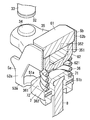
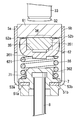
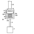
- FIG. 1 is an external perspective view of a contact device according to an embodiment of the present invention. It is a side view of the contact device of an embodiment of the present invention. It is a section perspective view of the contact device of an embodiment of the present invention. It is a section side view of the contact device of an embodiment of the present invention. It is an external appearance perspective view of the holding
- FIG. 6A is a cross-sectional view of an electromagnetic relay including the contact device according to the embodiment of the present invention, and FIG.
- FIG. 6B is another cross-sectional view of the electromagnetic relay including the contact device according to the embodiment of the present invention.
- FIG. 7A is an external view of an electromagnetic relay including the contact device according to the embodiment of the present invention
- FIG. 7B is another external view of the electromagnetic relay including the contact device according to the embodiment of the present invention.
- 8A is an exploded perspective view of an electromagnetic relay provided with a contact device according to an embodiment of the present invention
- FIG. 8B is another exploded perspective view of an electromagnetic relay provided with a contact device according to an embodiment of the present invention
- FIG. It is the further another exploded perspective view of the electromagnetic relay provided with the contact device of an embodiment.
- It is an external appearance perspective view of the other contact apparatus of embodiment of this invention.
- It is sectional drawing of the conventional contact apparatus. It is a side view of the conventional contact device.
- the contact device of this embodiment will be described with reference to FIGS. Note that the description will be made with reference to the vertical and horizontal directions in FIG.
- the up-down direction is the axial direction (first direction) of the movable shaft 8
- the left-right direction is the direction in which the movable contacts 34 are arranged in parallel (second direction)
- the front-back direction is the first direction.
- the upper and upper directions are defined as the first side in the first direction
- the lower and lower directions are defined as the second side in the first direction.
- the contact device of this embodiment includes a pair of fixed terminals 33 each having a fixed contact 32, a movable contact 35 having a pair of movable contacts 34, a contact pressure spring 36, The holding part 5, the adjustment plate 61, the yoke 62, and the spring receiving part 7 are provided.
- the contact device includes a movable shaft 8 and an electromagnet block (drive means) 2.
- the fixed terminal 33 is formed in a substantially cylindrical shape by a conductive material such as copper, and the fixed contact 32 is fixed to the lower end (first end in the first direction).
- the fixed contact 32 may be formed integrally with the fixed terminal 33.
- the movable contact 35 is formed in a flat plate shape that is long in the left-right direction, and a movable contact 34 is fixed to each of the left and right ends of the upper surface.
- the movable contact 34 is disposed at a position facing the fixed contact 32 with a predetermined interval.
- the movable contact 35 is formed with a narrow portion 351 having a narrow width in the front-rear direction at a substantially central portion in the left-right direction, and is fitted to the narrow portion 351. Is provided with a yoke 62.
- the yoke 62 is made of a magnetic material and has a substantially U-shaped cross section with an upper opening. And the yoke 62 is arrange
- a substantially disc-shaped positioning convex portion 621 is formed substantially at the center of the lower surface of the yoke 62 (one surface in the first direction).
- the contact pressure spring 36 is composed of a coil spring, and is disposed in a state where the axial direction is directed in the vertical direction.
- the positioning convex portion 621 is fitted into the upper end side inner diameter portion (first inner diameter portion) 361, whereby the yoke 62 And is positioned with respect to the movable contact 35.
- the spring receiving portion 7 is formed in a substantially rectangular plate shape from an electrically insulating material such as resin, for example, and is substantially on the disc at the approximate center of the upper surface (first surface in the first direction) 72.
- a positioning convex portion 71 is formed. Then, the positioning convex portion 71 is fitted into the lower end side inner diameter portion (second inner diameter portion) 362 of the contact pressure spring 36, whereby the spring receiving portion 7 and the contact pressure spring 36 are positioned.
- the adjustment plate 61 is made of a magnetic material such as pure iron (SUY) or cold-rolled steel plate (SPCC (Steel Plate Cold Commercial), SPCE (Steel Plate Cold deep drawn Extra)) in a substantially rectangular plate shape.
- the adjustment plate 61 is placed on the upper surface (first surface in the first direction) 352 of the substantially central portion (the narrow portion 351) in the left-right direction of the movable contact 35, and is fixed to the holding portion 5 described later.
- the holding unit 5 includes a first holding unit 5a and a second holding unit 5b.
- the first holding part 5a is made of a non-magnetic material such as stainless steel (SUS (Steel Use Stainless)), and has a first bottom plate 51a and a first side plate 52a.
- the second holding portion 5b is formed of a nonmagnetic material such as stainless steel (SUS), and has a second bottom plate 51b and a second side plate 52b.
- the first and second bottom plates 51a and 51b hold the movable contact 35, the yoke 62, and the contact pressure spring 36 in the vertical direction with the adjustment plate 61.
- the first and second side plates 52a and 52b are located above the front end (first end in the third direction) of the first bottom plate 51a and the rear end (second end in the third direction) of the second bottom plate 51b.
- the front end (first end in the third direction) and the rear end (second end in the third direction) of the movable contact 35 (yoke 62) are in sliding contact with each other.
- the adjustment plate 61 is held in the front-rear direction by contacting the front end (first end in the third direction) and the rear end (second end in the third direction) of the adjustment plate 61.
- the bottom plate 51 is divided in the front-rear direction, and is constituted by a first bottom plate 51a and a second bottom plate 51b. That is, the holding portion 5 includes a first holding portion 5a including a first bottom plate 51a and a first side plate 52a extending from the front end of the first bottom plate 51a, a second bottom plate 51b, and a second bottom plate 51a. It is divided into a second holding portion 5b composed of a second side plate 52b extending from the rear end of the bottom plate 51b.
- the first and second holding portions 5a and 5b form first and second bottom plates 51a and 51b and first and second side plates 52a and 52b by bending a plate-frame-like nonmagnetic material. is doing. Accordingly, the first bottom plate 51a and the first side plate 52a are continuous via the first bent portion 53a, and the second bottom plate 51b and the second side plate 52b are continuous via the second bent portion 53b. is doing. 3 and 4, the first and second holding portions 5a and 5b are integrally formed with the spring receiving portion 7 in a state of being separated from each other in the front-rear direction, and the bottom plate 51 (first and first) 2 between the bottom plates 51a and 51b) and the contact pressure spring 36. That is, the spring plate 7 is provided on the bottom plate 51 (first and second bottom plates 51a and 51b), and the bottom plate 51 and the contact pressure spring 36 are electrically insulated.
- the holding unit 5 of the present embodiment includes the first and second holding units 5a and 5b divided in the front-rear direction, and the first and second holding units 5a and 5b are separated from each other. It is integrally formed with the spring receiving portion 7 that is insulative in the state. Then, by sandwiching the adjustment plate 61 between the first and second side plates 52a and 52b, the first and second holding portions 5a and 5b are electrically connected only through the adjustment plate 61. Become.
- the movable shaft 8 is formed in a substantially rod-like shape that is long in the vertical direction, the electromagnet block 2 is connected to the lower end 83, and the upper end 82 is integrally formed with the spring receiving portion 7, thereby being connected to the holding portion 5. .
- the electromagnet block 2 drives the movable shaft 8 in the vertical direction so that the movable contact 34 contacts and separates from the fixed contact 32.
- initial contact pressure the contact pressure of the contact pressure spring 36 to the movable contact 35 at the time of opening when the movable contact 34 is separated from the fixed contact 32.
- the adjustment plate 61 By pressing the adjustment plate 61 downward, the adjustment plate 61, the movable contact 35, and the yoke 62 move downward against the urging force of the contact pressure spring 36, and the contact pressure spring against the yoke 62 (movable contact 35). 36 contact pressure is generated.
- the adjustment plate 61 is further moved downward, the initial contact pressure can be further increased, and when the adjustment plate 61 is moved upward, the initial contact pressure can be decreased.
- the front and rear ends (both ends in the third direction) of the adjustment plate 61 are fixed to the first and second side plates 52a and 52b at positions where the initial contact pressure becomes a predetermined value.
- the first and second holding portions 5a and 5b are integrally formed with the spring receiving portion 7 which is divided in a state of being separated in the front-rear direction and has insulating properties.
- the electrical connection is made only through the adjustment plate 61. Therefore, an electrode is brought into contact with each of the first and second side plates 52a and 52b, and an electric current is passed between the first and second side plates 52a and 52b only through the adjustment plate 61 to thereby adjust the first and second side plates 52a and 52b.
- the second holding portions 5a and 5b can be resistance-welded. Therefore, the adjustment plate 61 and the holding portion 5 (first and second holding portions 5a and 5b) can be easily fixed in a short time as compared with the conventional contact device, and the assemblability can be improved.
- the holding portion 5 has an opening 56 in the upward direction, which is the facing direction of the bottom plate 51, and the contact pressure spring 36, the yoke 62, and the movable contact 35 can be easily inserted into the holding portion 5 from the opening 56. Can be stored. Then, the adjustment plate 61 is inserted and fixed between the first and second side plates 52a and 52b so as to cover the opening 56 of the holding portion 5, so that the assembly of the parts to the holding portion 5 is facilitated. Assembling property can be improved.
- the holding unit 5 of the present embodiment includes a rear surface (first surface) 521 of the first side plate 52a and a front surface (second surface) 522 of the second side plate 52b that face each other in the front-rear direction.
- Two first protrusions 54a are formed on the rear surface (first surface in the third direction) 521 of the first side plate 52a, and the front surface (second in the third direction) of the second side plate 52b.
- Surface) 522 has two second convex portions 54b.
- the adjustment plate 61 When the adjustment plate 61 is inserted so as to cover the opening 56 of the holding portion 5, the first convex portion 54 a comes into contact with the front surface (the first surface in the third direction) of the adjustment plate 61, The second convex portion 54 b comes into contact with the rear surface (second surface in the third direction) of the adjustment plate 61. As a result, the adjustment plate 61 and the holding portion 5 (first and second holding portions 5a and 5b) can be projection welded. Thereby, the adjustment board 61 and the holding
- maintenance part 5a increases, and a welding state can be stabilized.
- two second convex portions 54b are formed on the second side plate 52b, the welding area between the adjusting plate 61 and the second holding portion 5b is increased, and the welding state can be stabilized.
- the number of the first convex portions 54a is not limited to two, and more first convex portions 54a may be formed.
- the number of the second protrusions 54b is not limited to two, and more second protrusions 54b may be formed.
- the convex portions 54a and 54b are formed on the front side of the first side plate 52a, the rear side of the second side plate 52b, and the rear side of the first side plate 52a and the front side of the second side plate 52b.
- the convex portions 54a and 54b can be easily formed. That is, the first convex portion 54a is formed on the rear surface 521 of the first side plate 52a by extrusion from the front surface (third surface in the third direction) 523 side of the first side plate 52a.
- the convex portion 54a can be easily formed.
- the second convex portion 54b is formed on the front surface 522 of the second side plate 52b by extrusion from the rear surface (fourth surface in the third direction) 524 side of the second side plate 52b, and the second convex portion 54b can be formed easily. Further, the two first and second convex portions 54a and 54b formed on each of the first and second side plates 52a and 52b are on the same plane (the rear surface 521 and the second side plate of the first side plate 52a). 52b, the height of the convex portions 54a and 54b can be easily managed.
- the first holding part 5a includes first protrusions 57a and 58a.
- the first protrusions 57a and 58a are provided integrally with the first side plate 52a at both ends in the left-right direction (first direction) of the first side plate 52a.
- the second holding part 5b includes second protrusions 57b and 58b.
- the second protrusions 57b, 58b are provided integrally with the second side plate 52b at both ends in the left-right direction (first direction) of the second side plate 52b.
- the spring receiving portion 7 is provided on the bottom plate 51 (first and second bottom plates 51a and 51b) of the holding portion 5, and the first and second bottom plates 51a and 51b and the first and second bottom plates 51a and 51b are provided.
- First and second bent portions 53 a and 53 b that are continuous with the second side plates 52 a and 52 b are exposed from the spring receiving portion 7. Therefore, after the holding portion 5 and the spring receiving portion 7 are integrally formed, the first and second bent portions 53a and 53b can be formed by bending, and the first and second bottom plates 51a and 51b can be formed.
- the first and second side plates 52a and 52b can be easily formed.
- the spring receiving portion 7 of the present embodiment is formed in a rectangular plate shape having a predetermined thickness in the vertical direction, and includes a side surface (front surface (third surface in the third direction) 74, rear surface (third direction).
- the fourth surface) 75, the left surface (fifth surface in the second direction) 76, and the right surface (sixth surface in the second direction) 77) are formed in a planar shape. Therefore, when the contact device is assembled, the side surfaces (the front surface 74 and the rear surface 75 or the left surface 76 and the right surface 77) facing each other of the spring receiving portion 7 can be chucked, and assemblability can be improved.
- the upper surface (first surface in the first direction) 72 and the lower surface (second surface in the first direction) 73 of the spring receiving portion 7 may be chucked.
- the adjustment plate 61 of the present embodiment is plated and coated with a film thickness of, for example, 20 ⁇ m or less. Thereby, welding with the adjustment board 61 and the 1st, 2nd holding
- the adjustment plate 61 disposed above the movable contact 35 and the yoke 62 disposed below the movable contact 35 are formed of a magnetic material, and the holding portion 5 (first 1 and 2nd holding
- a magnetic attraction force acts between the adjusting plate 61 and the yoke 62, and this magnetic attraction force suppresses an electromagnetic repulsive force generated between the fixed contact 32 and the movable contact 34, and between the fixed contact 32 and the movable contact 34.
- a decrease in contact pressure can be suppressed.
- the holding portion 5 and the spring receiving portion 7 are integrally formed, and the spring receiving portion 7 is interposed between the bottom plate 51 (first and second bottom plates 51a and 51b) and the contact pressure spring 36. I am letting.
- the bottom plate 51 and the contact pressure spring 7 are insulated, and the first and second holding portions 5a and 5b are configured to be electrically connected only through the adjustment plate 61.
- the present invention is not limited to this configuration, and the spring receiving portion 7 may be omitted, and the contact pressure spring 36 may be directly provided on the first and second bottom plates 51a and 51b.
- at least one of the first and second bottom plates 51a and 51b and the contact pressure spring 36 is formed of an electrically insulating material.
- first and second holding portions 5a and 5b are configured not to be electrically connected via the contact pressure spring 36 but to be electrically connected only via the adjustment plate 61.
- the first and second holding portions 5a and 5b and the adjustment plate 61 can be resistance-welded.
- the holding portion 5 and the adjustment plate 61 constitute a spring load (initial contact pressure) adjustment structure and a spring load (initial contact pressure) adjustment method.
- maintenance part 5a, 5b is electrically connected only through the adjustment board 61, the adjustment board 61 and the 1st, 2nd holding
- the operation of the contact device of the present embodiment having the above configuration will be described.
- the movable shaft 8 is displaced upward by the electromagnet block (driving means) 2
- the spring receiving portion 7 and the holding portion 5 connected to the movable shaft 8 are also displaced upward.
- the movable contact 35 also moves upward, the movable contact 34 abuts on the fixed contact 32, and the contacts are conducted.
- the contact pressure of the contact pressure spring 36 with respect to the movable contact 35 is adjusted as described above, the contact pressures acting between the movable contact 34 and the fixed contact 32 in each of the plurality of contact devices can be reduced. Can be approximately equal. Therefore, it is not necessary to increase the size of the electromagnet block 2, and the contact device can be prevented from being enlarged.
- the adjustment plate 61 is accommodated between the first and second side plates 52a and 52b, it is not necessary to provide a separate space for accommodating the adjustment plate 61, thereby preventing an increase in the size of the contact device. Can do.
- the initial contact pressure can be adjusted by changing the position of the adjustment plate 61 in the vertical direction.
- the adjusted initial contact pressure is maintained. Therefore, in order to maintain the initial contact pressure and the initial contact pressure after the adjustment, no additional member is required, thereby preventing an increase in manufacturing cost.
- the contact device of the present embodiment is used for an electromagnetic relay as shown in FIGS. 6A and 6B, for example.
- the electromagnetic relay is obtained by combining an electromagnet block (driving means) 2 and a contact block 3 in a hollow box-shaped housing 4.
- the constructed internal unit block 1 is accommodated.
- a direction orthogonal to the up / down / left / right direction is defined as the front / rear direction with reference to the up / down / left / right direction in FIG. 6A.
- the electromagnet block 2 includes a coil bobbin 21 around which the excitation winding 22 is wound, a pair of coil terminals 23 to which both ends of the excitation winding 22 are connected, a fixed iron core 24 disposed and fixed in the coil bobbin 21, and a movable An iron core 25, a yoke 26, and a return spring 27 are provided.
- the coil bobbin 21 is formed of a resin material in a substantially cylindrical shape in which flanges 21a and 21b are formed at the upper end (first end in the first direction) and the lower end (second end in the first direction). , 21b, an excitation winding 22 is wound around the cylindrical portion 21c.
- the inner diameter of the cylindrical portion 21c on the lower end (second end in the first direction) side is larger than the inner diameter on the upper end (first end in the first direction) side.
- the excitation winding 22 has ends connected to a pair of terminal portions 121 provided on the flange portion 21 a (see FIG. 8B) of the coil bobbin 21, and a lead wire 122 connected to the terminal portion 121.
- a pair of coil terminals 23 are connected to a pair of coil terminals 23, respectively.
- the coil terminal 23 is formed of a conductive material such as copper and is connected to the lead wire 122 by solder or the like.
- the yoke 26 includes a yoke plate 261 disposed on the upper end side of the coil bobbin 21, a yoke plate 262 disposed on the lower end side of the coil bobbin 21, and both left and right ends of the yoke plate 262 (first 2) and a pair of yoke plates 263 extending to the yoke plate 261 side.
- the yoke plate 261 is formed in a substantially rectangular plate shape, and a recess 26a is formed in the approximate center of the upper surface side, and an insertion hole 26c is formed in the approximate center of the recess 26a.
- the bottomed cylindrical cylindrical member 28 in which the collar part 28a is formed in the upper end (first end in the first direction) is inserted into the insertion hole 26c, and the collar part 28a is inserted into the yoke plate 261 and the collar part 21a.
- a movable iron core 25 formed in a substantially columnar shape from a magnetic material is disposed on the lower end (second end in the first direction) side in the cylindrical portion 28b of the cylindrical member 28.
- a fixed iron core 24 that is formed in a substantially cylindrical shape from a magnetic material and faces the movable iron core 25 in the axial direction is disposed in the cylindrical portion 28b.
- a substantially disc-shaped cap member 45 whose peripheral portion is fixed to the opening peripheral edge of the insertion hole 26c in the yoke plate 261.
- the cap member 45 prevents the fixed iron core 24 from coming off. Is made.
- the cap member 45 has a concave portion 45a formed in a substantially cylindrical shape in the upper center thereof, and is formed at the upper end (first end in the first direction) of the fixed iron core 24 in the concave portion 45a.
- the collar part 24a is stored.
- a cylindrical bush 264 made of a magnetic material is fitted into a gap formed between the inner peripheral surface on the lower end side of the coil bobbin 21 and the outer peripheral surface of the cylindrical member 28.
- the bush 264 forms a magnetic circuit together with the yoke plates 261 to 263, the fixed iron core 24, and the movable iron core 25.
- the return spring 27 is inserted through the through-hole (inner diameter) 24b of the fixed core 24, and the lower end (second end in the first direction) abuts the upper surface (one surface in the first direction) of the movable core 25, and the upper end The (first end in the first direction) contacts the lower surface (one surface in the first direction) of the cap member 45.
- the return spring 27 is provided in a compressed state between the movable iron core 25 and the cap member 45, and elastically biases the movable iron core 25 downward.
- the contact block 3 includes a case 31, a pair of fixed terminals 33, a movable contact 35, a contact pressure spring 36, a holding portion 5, an adjustment plate 61, a yoke 62, a spring receiving portion 7, and a movable shaft 8.
- the movable shaft 8 is formed in a substantially round bar shape that is long in the vertical direction, and a screw groove 81 is formed by forming a screw groove on the lower end 83 side.
- the lower end 83 side of the movable shaft 8 is inserted through the insertion hole 45b formed at the approximate center of the recess 45a in the cap member 45 and the return spring 27, and the screw portion 81 is formed in the movable core 25 along the axial direction. Screwed into the screw hole 25a. Thereby, the movable shaft 8 and the movable iron core 25 are connected.
- the upper end 82 of the movable shaft 8 is connected to the spring receiving portion 7.
- the case 31 is formed in a hollow box shape whose bottom surface is opened from a heat resistant material such as ceramic, and two through holes 31a are arranged in parallel on the top surface.
- the fixed terminal 33 is formed in a substantially cylindrical shape using a conductive material such as copper, and has a flange 33a formed at the upper end (second end in the first direction), and at the lower end (first end in the first direction).
- a fixed contact 32 is provided.
- the fixed terminal 33 is inserted into the through hole 31 a of the case 31 and joined to the case 31 by brazing in a state where the flange portion 33 a protrudes from the upper surface of the case 31.
- one end (first end in the first direction) 381 of the coupling body 381 is joined to the peripheral edge of the opening of the case 31 by brazing. Then, the other end (second end in the first direction) 382 of the coupling body 38 is joined to the first yoke plate 261 by brazing.
- an insulating member 39 for insulating an arc generated between the fixed contact 32 and the movable contact 34 from a joint portion between the case 31 and the coupling body 38 is provided at the opening of the case 31.
- the insulating member 39 is formed in a substantially hollow rectangular parallelepiped shape with an upper surface opened from an insulating material such as ceramic or synthetic resin, and the upper end (one end in the first direction) side of the peripheral wall is in contact with the inner surface of the peripheral wall of the case 31. Thereby, the insulation between the contact portion composed of the fixed contact 32 and the movable contact 34 and the joint portion of the case 31 and the coupling body 38 is achieved.
- an insertion hole 39b through which the movable shaft 8 is inserted is formed at substantially the center of the inner bottom surface of the insulating member 39.
- the housing 4 is formed from a resin material in a substantially rectangular box shape, and includes a hollow box-type housing main body 41 having an open top surface and a hollow box-type cover 42 covering the opening of the housing main body 41.
- the housing body 41 is provided with a protrusion 141 having an insertion hole 141a formed at the front end of the left and right side walls, which is used when the electromagnetic relay is fixed to the mounting surface by screwing. Further, a step portion 41a is formed on the opening peripheral edge of the housing main body 41 on the upper end (first end in the first direction) side, and the upper end is the outer periphery as compared with the lower end (second end in the first direction) side. Is getting smaller.
- the step portion 41a is formed with a pair of slits 41b into which the terminal portion 23b of the coil terminal 23 is fitted. Furthermore, a pair of protrusions 41c are juxtaposed in the left-right direction on the step 41a.
- the cover 42 is formed in a hollow box shape whose bottom surface is open, and a pair of holes 42a into which the protrusions 41c of the housing body 41 are fitted when assembled to the housing body 41 are formed.
- a partition 42c is formed on the upper surface of the cover 42 to divide the upper surface into two substantially right and left, and a pair of insertion holes 42b through which the fixed terminals 33 are inserted are formed on the upper surface divided into two by the partition 42c. It is formed.
- the coil bobbin 21 has a substantially lower portion between the flange 21 b at the lower end and the bottom surface of the housing body 41.
- a rectangular lower cushion rubber 43 is interposed.
- an upper cushion rubber 44 in which an insertion hole 44 a through which the flange portion 33 a of the fixed terminal 33 is inserted is interposed between the case 31 and the cover 42.
- the movable iron core 25 slides downward by the urging force of the return spring 27, and the movable shaft 8 moves downward accordingly. Accordingly, when the movable contact 35 is pressed downward by the adjustment plate 61, the movable contact 35 moves downward together with the adjustment plate 61. Therefore, the movable contact 34 is separated from the fixed contact 32 in the initial state.
- the said electromagnetic relay since the said electromagnetic relay is provided with the contact apparatus of this embodiment, it can adjust initial contact pressure easily. Moreover, since the dispersion
- the pair of movable contacts 34 is provided separately from the movable contact 35 and is fixed to the movable contact 35, but the contact device of the present embodiment is The configuration is not limited to the above.
- the pair of movable contacts 34 a are part of the movable contact 35 and may be provided integrally with the movable contact 35. That is, in the movable contact 35 shown in FIG. 9, both end portions in the left-right direction (second direction) are regions of the movable contact 34a.
- the region of the movable contact 34a swells above the center portion 35b (first side in the first direction), that is, toward the fixed contact 32 in the axial direction (first direction) of the movable shaft 8.
- the movable contact 35 is formed in a concave shape when viewed from the third direction. Also in the contact device as shown in FIG. 9, the movable contact 35 a integrally formed with the movable contact 34 a moves due to the movement of the movable shaft 8, and the movable contact 34 a contacts and separates from the fixed contact 32.
Landscapes
- Physics & Mathematics (AREA)
- Electromagnetism (AREA)
- Contacts (AREA)
- Breakers (AREA)
- Coupling Device And Connection With Printed Circuit (AREA)
Abstract
Description
本実施形態の接点装置について図1~4を用いて説明を行う。なお、図1における上下左右を基準とし、上下左右方向と直交する方向を前後方向として説明を行う。上下方向は、可動軸8の軸方向(第1の方向)であり、左右方向は、可動接点34が並設されている方向(第2の方向)であり、前後方向は、第1の方向および第2の方向と直交する第3の方向である。また、上下方向において、上方および上方向を第1の方向の第1の側とし、下方および下方向を第1の方向の第2の側とする。 (Embodiment)
The contact device of this embodiment will be described with reference to FIGS. Note that the description will be made with reference to the vertical and horizontal directions in FIG. The up-down direction is the axial direction (first direction) of the
Claims (14)
- 固定接点を有する固定端子と、
前記固定接点に接離する可動接点を一面に有する可動接触子と、
前記可動接点の接離方向に伸縮して前記可動接触子を前記固定接点側へ付勢する接圧ばねと、
前記可動接触子の一面に当接する調整板と、
前記可動接点の前記接離方向において前記可動接触子および前記接圧ばねを前記調整板とで挟持する底板および、前記底板から延設され前記可動接触子の側端が摺接する側板を有する保持部と、
一端側が前記保持部に連結される可動軸と、
前記可動接点が前記固定接点に接離するように前記可動軸を軸方向に駆動させる駆動手段とを備える接点装置のばね負荷調整構造であって、
前記保持部は、第1の保持部と第2の保持部とに分割されており、
前記底板は、前記第1の保持部が備える第1の底板と、前記第2の保持部が備える第2の底板とを含み、
前記側板は、前記第1の保持部が備える第1の側板と、前記第2の保持部が備える第2の側板とを含み、
前記第1,第2の保持部は、互いに離間した状態で設けられ、互いに対向する前記第1の側板と前記第2の側板とで前記調整板を挟持することで、前記第1,第2の保持部は前記調整板のみを介して互いに電気的に接続され、
前記接圧ばねの伸縮方向へ前記調整板を移動させることで前記底板と前記調整板との間の距離を変化させ、前記可動接触子に対する前記接圧ばねの接圧が予め設定された値となる位置において、前記調整板と前記第1,第2の側板の各々とが抵抗溶接されることを特徴とする接点装置のばね負荷調整構造。 A fixed terminal having a fixed contact;
A movable contact having a movable contact on and away from the fixed contact;
A contact pressure spring that expands and contracts in the contact / separation direction of the movable contact and biases the movable contact toward the fixed contact;
An adjustment plate that contacts one surface of the movable contact;
A holding portion having a bottom plate that sandwiches the movable contact and the contact pressure spring with the adjustment plate in the contact / separation direction of the movable contact, and a side plate that extends from the bottom plate and is in sliding contact with a side end of the movable contact When,
A movable shaft having one end connected to the holding portion;
A spring load adjustment structure for a contact device, comprising: a driving means for driving the movable shaft in an axial direction so that the movable contact contacts and separates from the fixed contact;
The holding part is divided into a first holding part and a second holding part,
The bottom plate includes a first bottom plate provided in the first holding unit and a second bottom plate provided in the second holding unit,
The side plate includes a first side plate provided in the first holding unit and a second side plate provided in the second holding unit,
The first and second holding portions are provided in a state of being separated from each other, and the first and second holding plates are sandwiched between the first side plate and the second side plate facing each other, thereby The holding portions are electrically connected to each other only through the adjustment plate,
The distance between the bottom plate and the adjustment plate is changed by moving the adjustment plate in the expansion / contraction direction of the contact pressure spring, and the contact pressure of the contact pressure spring with respect to the movable contact is a preset value. A spring load adjustment structure for a contact device, wherein the adjustment plate and each of the first and second side plates are resistance-welded at a position. - 前記底板と前記接圧ばねとは互いに絶縁されていることを特徴とする請求項1記載の接点装置のばね負荷調整構造。 2. The spring load adjustment structure for a contact device according to claim 1, wherein the bottom plate and the contact pressure spring are insulated from each other.
- 前記底板と前記接圧ばねとの間に設けられるばね受け部を備え、
前記ばね受け部は、電気的に絶縁性を有する材料で形成されることを特徴とする請求項1または2記載の接点装置のばね負荷調整構造。 A spring receiving portion provided between the bottom plate and the contact pressure spring;
3. The spring load adjusting structure for a contact device according to claim 1, wherein the spring receiving portion is made of an electrically insulating material. - 前記第1の保持部は、前記第1の底板と前記第1の側板とが第1の屈曲部を介して連続しており、
前記第2の保持部は、前記第2の底板と前記第2の側板とが第2の屈曲部を介して連続しており、
前記ばね受け部は、前記底板に設けられており、
前記第1,第2の屈曲部は、前記ばね受け部から露出することを特徴とする請求項3記載の接点装置のばね負荷調整構造。 In the first holding portion, the first bottom plate and the first side plate are continuous via a first bent portion,
In the second holding portion, the second bottom plate and the second side plate are continuous via a second bent portion,
The spring receiving portion is provided on the bottom plate,
4. The spring load adjustment structure for a contact device according to claim 3, wherein the first and second bent portions are exposed from the spring receiving portion. - 前記ばね受け部は、互いに対向する平面を外面に有することを特徴とする請求項3または4記載の接点装置のばね負荷調整構造。 The spring load adjusting structure for a contact device according to claim 3 or 4, wherein the spring receiving portion has flat surfaces facing each other on the outer surface.
- 前記第1の側板は、前記第2の側板と対向する第1面に第1の凸部が形成され、前記第2の側板は、前記第1の側板と対向する第2面に第2の凸部が形成されており、
前記第1,第2の凸部の各々の先端が前記調整板に当接した状態で、前記調整板と前記第1,第2の側板の各々とがプロジェクション溶接されることを特徴とする請求項1乃至5のうちいずれか1項に記載の接点装置のばね負荷調整構造。 The first side plate has a first convex portion formed on a first surface facing the second side plate, and the second side plate has a second surface on the second surface facing the first side plate. A convex part is formed,
The adjustment plate and each of the first and second side plates are projection welded in a state where the tips of the first and second convex portions are in contact with the adjustment plate. Item 6. The spring load adjustment structure for a contact device according to any one of Items 1 to 5. - 前記第1の凸部は、前記第1の側板の前記第1面とは反対面となる第3面側からの押し出しによって前記第1の側板の前記第1面側に形成され、前記第2の凸部は、前記第2の側板の前記第2面とは反対面となる第4面側からの押し出しによって前記第2の側板の前記第2面側に形成されることを特徴とする請求項6記載の接点装置のばね負荷調整構造。 The first convex portion is formed on the first surface side of the first side plate by extrusion from a third surface side opposite to the first surface of the first side plate. The convex portion is formed on the second surface side of the second side plate by extrusion from the fourth surface side which is the surface opposite to the second surface of the second side plate. Item 7. A spring load adjustment structure for a contact device according to Item 6.
- 前記第1の側板は、複数の前記第1の凸部が形成され、前記第2の側板は、複数の前記第2の凸部が形成されることを特徴とする請求項6または7記載の接点装置のばね負荷調整構造。 The said 1st side plate is formed with several said 1st convex part, The said 2nd side plate is formed with several said 2nd convex part, The Claim 6 or 7 characterized by the above-mentioned. Spring load adjustment structure for contact device.
- 複数の前記第1の凸部は、前記第1の側板の同一平面上に形成され、複数の前記第2の凸部は、前記第2の側板の同一平面上に形成されることを特徴とする請求項8記載の接点装置のばね負荷調整構造。 The plurality of first protrusions are formed on the same plane of the first side plate, and the plurality of second protrusions are formed on the same plane of the second side plate. The spring load adjusting structure for a contact device according to claim 8.
- 前記第1の側板は、前記第1面とは反対面となる第3面側が平面状に形成され、前記第2の側板は、前記第2面とは反対面となる第4面側が平面状に形成されることを特徴とする請求項6乃至9のうちいずれか1項に記載の接点装置のばね負荷調整構造。 The first side plate is formed in a planar shape on the third surface side opposite to the first surface, and the second side plate is planar on the fourth surface side opposite to the second surface. The spring load adjusting structure for a contact device according to any one of claims 6 to 9, wherein the spring load adjusting structure is formed as follows.
- 前記保持部は、前記可動接点の前記接離方向において前記底板に対向して開口部を有しており、当該開口部を覆う前記調整板が前記第1,第2の側板の各々に溶接されることを特徴とする請求項1乃至10のうちいずれか1項に記載の接点装置のばね負荷調整構造。 The holding portion has an opening facing the bottom plate in the contact / separation direction of the movable contact, and the adjustment plate covering the opening is welded to each of the first and second side plates. 11. The spring load adjustment structure for a contact device according to claim 1, wherein the spring load adjustment structure is a contact device.
- 前記調整板は、メッキコーティングされていることを特徴とする請求項1乃至11のうちいずれか1項に記載の接点装置のばね負荷調整構造。 12. The spring load adjustment structure for a contact device according to any one of claims 1 to 11, wherein the adjustment plate is plated.
- 前記調整板は、磁性体材料で形成され、前記保持部は、非磁性体材料で形成されることを特徴とする請求項1乃至12のうちいずれか1項に記載の接点装置のばね負荷調整構造。 The spring load adjustment of the contact device according to any one of claims 1 to 12, wherein the adjustment plate is made of a magnetic material, and the holding portion is made of a non-magnetic material. Construction.
- 固定接点を有する固定端子と、
前記固定接点に接離する可動接点を一面に有する可動接触子と、
前記可動接点の接離方向に伸縮して前記可動接触子を前記固定接点側へ付勢する接圧ばねと、
前記可動接触子の一面に当接する調整板と、
前記可動接点の前記接離方向において前記可動接触子および前記接圧ばねを前記調整板とで挟持する底板および、前記底板から延設され前記可動接触子の側端が摺接する側板を有する保持部と、
一端側が前記保持部に連結される可動軸と、
前記可動接点が前記固定接点に接離するように前記可動軸を軸方向に駆動させる駆動手段とを備える接点装置のばね負荷調整方法であって、
前記保持部は、第1の保持部と第2の保持部とに分割されており、
前記底板は、前記第1の保持部が備える第1の底板と、前記第2の保持部が備える第2の底板とを含み、
前記側板は、前記第1の保持部が備える第1の側板と、前記第2の保持部が備える第2の側板とを含み、
前記第1,第2の保持部を、互いに離間した状態で設け、互いに対向する前記第1の側板と前記第2の側板とで前記調整板を挟持することで、前記第1,第2の保持部を、前記調整板のみを介して互いに電気的に接続し、
前記接圧ばねの伸縮方向へ前記調整板を移動させることで前記底板と前記調整板との間の距離を変化させ、前記可動接触子に対する前記接圧ばねの接圧が予め設定された値となる位置において、前記調整板と前記第1,第2の側板の各々とを抵抗溶接することを特徴とする接点装置のばね負荷調整方法。 A fixed terminal having a fixed contact;
A movable contact having a movable contact on and away from the fixed contact;
A contact pressure spring that expands and contracts in the contact / separation direction of the movable contact and biases the movable contact toward the fixed contact;
An adjustment plate that contacts one surface of the movable contact;
A holding portion having a bottom plate that sandwiches the movable contact and the contact pressure spring with the adjustment plate in the contact / separation direction of the movable contact, and a side plate that extends from the bottom plate and is in sliding contact with a side end of the movable contact When,
A movable shaft having one end connected to the holding portion;
A spring load adjustment method for a contact device, comprising: a drive unit that drives the movable shaft in an axial direction so that the movable contact is in contact with and away from the fixed contact;
The holding part is divided into a first holding part and a second holding part,
The bottom plate includes a first bottom plate provided in the first holding unit and a second bottom plate provided in the second holding unit,
The side plate includes a first side plate provided in the first holding unit and a second side plate provided in the second holding unit,
The first and second holding portions are provided in a state of being separated from each other, and the first and second side plates opposed to each other sandwich the adjustment plate, whereby the first and second holding portions are sandwiched between the first side plate and the second side plate. The holding portions are electrically connected to each other only through the adjustment plate,
The distance between the bottom plate and the adjustment plate is changed by moving the adjustment plate in the expansion / contraction direction of the contact pressure spring, and the contact pressure of the contact pressure spring with respect to the movable contact is a preset value. A spring load adjustment method for a contact device, wherein the adjustment plate and each of the first and second side plates are resistance-welded at a position.
Priority Applications (5)
| Application Number | Priority Date | Filing Date | Title |
|---|---|---|---|
| EP13775740.7A EP2838103B1 (en) | 2012-04-09 | 2013-04-08 | Contact device spring load adjustment structure and contact device spring load adjustment method |
| CN201380019143.0A CN104221119B (en) | 2012-04-09 | 2013-04-08 | The load on spring of contact making device adjusts structure and the load on spring method of adjustment of contact making device |
| US14/390,326 US9269507B2 (en) | 2012-04-09 | 2013-04-08 | Spring load adjustment structure of contact device and spring load adjustment method of contact device |
| JP2014510052A JP6064262B2 (en) | 2012-04-09 | 2013-04-08 | Spring load adjustment structure for contact device and spring load adjustment method for contact device |
| KR1020147030914A KR20140145189A (en) | 2012-04-09 | 2013-04-08 | Contact device spring load adjustment structure and contact device spring load adjustment method |
Applications Claiming Priority (2)
| Application Number | Priority Date | Filing Date | Title |
|---|---|---|---|
| JP2012088838 | 2012-04-09 | ||
| JP2012-088838 | 2012-04-09 |
Publications (1)
| Publication Number | Publication Date |
|---|---|
| WO2013153799A1 true WO2013153799A1 (en) | 2013-10-17 |
Family
ID=49327383
Family Applications (1)
| Application Number | Title | Priority Date | Filing Date |
|---|---|---|---|
| PCT/JP2013/002393 WO2013153799A1 (en) | 2012-04-09 | 2013-04-08 | Contact device spring load adjustment structure and contact device spring load adjustment method |
Country Status (6)
| Country | Link |
|---|---|
| US (1) | US9269507B2 (en) |
| EP (1) | EP2838103B1 (en) |
| JP (1) | JP6064262B2 (en) |
| KR (1) | KR20140145189A (en) |
| CN (1) | CN104221119B (en) |
| WO (1) | WO2013153799A1 (en) |
Cited By (4)
| Publication number | Priority date | Publication date | Assignee | Title |
|---|---|---|---|---|
| CN105070591A (en) * | 2015-07-20 | 2015-11-18 | 昆山国力真空电器有限公司 | Sealed-type DC contactor |
| WO2020148995A1 (en) * | 2019-01-18 | 2020-07-23 | オムロン株式会社 | Relay |
| JP2022503584A (en) * | 2019-08-08 | 2022-01-12 | 東莞市中匯瑞徳電子股▲ふん▼有限公司 | High-capacity relay short-circuit prevention structure |
| JP7463472B2 (en) | 2021-10-28 | 2024-04-08 | ティーイー コネクティビティ ジャーマニー ゲゼルシャフト ミット ベシュレンクテル ハフツンク | SWITCHING CONTACT ASSEMBLY FOR ELECTRICAL SWITCHING ELEMENT AND ELECTRICAL SWITCHING ELEMENT - Patent application |
Families Citing this family (22)
| Publication number | Priority date | Publication date | Assignee | Title |
|---|---|---|---|---|
| KR101406357B1 (en) * | 2010-07-16 | 2014-06-12 | 파나소닉 주식회사 | Contact apparatus |
| EP2889892B1 (en) * | 2012-08-23 | 2017-02-01 | Panasonic Intellectual Property Management Co., Ltd. | Contact device |
| JP6590273B2 (en) * | 2015-04-13 | 2019-10-16 | パナソニックIpマネジメント株式会社 | Contact device and electromagnetic relay |
| JP6528271B2 (en) * | 2015-04-13 | 2019-06-12 | パナソニックIpマネジメント株式会社 | Contact device and electromagnetic relay |
| KR101943364B1 (en) * | 2015-04-23 | 2019-04-17 | 엘에스산전 주식회사 | Magnetic Switch |
| JP6681579B2 (en) * | 2015-07-01 | 2020-04-15 | パナソニックIpマネジメント株式会社 | Electromagnet device and electromagnetic relay using the same |
| KR101943365B1 (en) | 2015-10-14 | 2019-01-29 | 엘에스산전 주식회사 | Direct Relay |
| CN105551897B (en) * | 2015-12-22 | 2018-11-02 | 厦门宏发电力电器有限公司 | A kind of high voltage direct current relay and its assembly method |
| CN105551894B (en) * | 2016-02-18 | 2018-03-30 | 常州市吉士电器有限公司 | High power D.C. contactor movable contact structure |
| CN105895452B (en) * | 2016-05-27 | 2017-11-10 | 浙江英洛华新能源科技有限公司 | Closed type HVDC relay |
| CN106783404B (en) * | 2016-12-30 | 2019-09-03 | 陈德言 | A kind of relay elastic slice apparatus for shaping |
| CN107170648A (en) * | 2017-07-11 | 2017-09-15 | 珠海格力电器股份有限公司 | Contactor and heat exchange equipment with same |
| US10262810B1 (en) * | 2017-11-08 | 2019-04-16 | Ford Global Technologies, Llc | Moveable contact support structure and supporting method |
| DE102018204014A1 (en) | 2018-03-16 | 2019-09-19 | Te Connectivity Germany Gmbh | Assembly for the galvanic isolation of an armature and a switching bridge of a relay arranged on a switching bridge carrier, and relays |
| KR20200000311A (en) * | 2018-08-31 | 2020-01-02 | 엘에스산전 주식회사 | Direct Current Relay |
| KR20200000312A (en) * | 2018-08-31 | 2020-01-02 | 엘에스산전 주식회사 | Direct Current Relay |
| EP3879553B1 (en) | 2018-11-09 | 2024-01-10 | Xiamen Hongfa Electric Power Controls Co., Ltd. | Direct-current relay resistant to short-circuit current |
| KR102324515B1 (en) * | 2019-05-29 | 2021-11-10 | 엘에스일렉트릭 (주) | Direct current relay and method of fabrication thereof |
| CN110223883A (en) * | 2019-07-09 | 2019-09-10 | 东莞市中汇瑞德电子股份有限公司 | The pushing structure of high voltage direct current relay |
| US12080499B2 (en) * | 2022-01-07 | 2024-09-03 | TE Connectivity Solutions GmbH-CH | Contactor with movable contact |
| FR3138731A1 (en) * | 2022-08-05 | 2024-02-09 | Safran Electrical & Power | ELECTRIC CONTACTOR COMPRISING A QUICK CONTACT DRIVE SPRING |
| CN115642056B (en) * | 2022-11-17 | 2023-03-21 | 东莞市中汇瑞德电子股份有限公司 | High-voltage direct-current relay with auxiliary contacts |
Citations (3)
| Publication number | Priority date | Publication date | Assignee | Title |
|---|---|---|---|---|
| JP2004303633A (en) * | 2003-03-31 | 2004-10-28 | Matsushita Electric Works Ltd | Contact arrangement |
| JP2012048908A (en) * | 2010-08-25 | 2012-03-08 | Panasonic Electric Works Co Ltd | Spring load adjustment structure and spring load adjustment method of contact device |
| JP2012048907A (en) | 2010-08-25 | 2012-03-08 | Panasonic Electric Works Co Ltd | Spring load adjustment structure and spring load adjustment method of contact device |
Family Cites Families (13)
| Publication number | Priority date | Publication date | Assignee | Title |
|---|---|---|---|---|
| US5892194A (en) * | 1996-03-26 | 1999-04-06 | Matsushita Electric Works, Ltd. | Sealed contact device with contact gap adjustment capability |
| DE29701312U1 (en) * | 1997-01-28 | 1997-04-10 | Klöckner-Moeller GmbH, 53115 Bonn | Contact bridge bracket |
| DE29823818U1 (en) * | 1998-03-31 | 1999-12-09 | Moeller GmbH, 53115 Bonn | Electromagnetic switching device with magnetic drive and bridge system |
| DE60214666T2 (en) * | 2001-11-29 | 2007-09-13 | Matsushita Electric Works, Ltd., Kadoma | ELECTROMAGNETIC SWITCHING DEVICE |
| JP2005026182A (en) * | 2003-07-02 | 2005-01-27 | Matsushita Electric Works Ltd | Electromagnetic switching device |
| WO2007060945A1 (en) * | 2005-11-25 | 2007-05-31 | Matsushita Electric Works, Ltd. | Electromagnetic switch |
| JP2007305467A (en) * | 2006-05-12 | 2007-11-22 | Omron Corp | Electromagnetic relay, its adjustment method, and adjustment system |
| DE102007048424B3 (en) * | 2007-10-09 | 2009-06-18 | Siemens Ag | Contact holder unit for e.g. sliding valve, has support for positioning spring element at switching bridge, where locking device of protrusion of support and/or of contact holder is arranged at outer side of protrusion |
| US9087655B2 (en) * | 2010-03-25 | 2015-07-21 | Panasonic Intellectual Property Management Co., Ltd. | Contact device |
| KR101406357B1 (en) * | 2010-07-16 | 2014-06-12 | 파나소닉 주식회사 | Contact apparatus |
| JP2012022982A (en) * | 2010-07-16 | 2012-02-02 | Panasonic Electric Works Co Ltd | Contact device |
| JP5938745B2 (en) * | 2012-07-06 | 2016-06-22 | パナソニックIpマネジメント株式会社 | Contact device and electromagnetic relay equipped with the contact device |
| EP2889892B1 (en) * | 2012-08-23 | 2017-02-01 | Panasonic Intellectual Property Management Co., Ltd. | Contact device |
-
2013
- 2013-04-08 KR KR1020147030914A patent/KR20140145189A/en not_active Application Discontinuation
- 2013-04-08 WO PCT/JP2013/002393 patent/WO2013153799A1/en active Application Filing
- 2013-04-08 EP EP13775740.7A patent/EP2838103B1/en active Active
- 2013-04-08 CN CN201380019143.0A patent/CN104221119B/en active Active
- 2013-04-08 JP JP2014510052A patent/JP6064262B2/en active Active
- 2013-04-08 US US14/390,326 patent/US9269507B2/en active Active
Patent Citations (3)
| Publication number | Priority date | Publication date | Assignee | Title |
|---|---|---|---|---|
| JP2004303633A (en) * | 2003-03-31 | 2004-10-28 | Matsushita Electric Works Ltd | Contact arrangement |
| JP2012048908A (en) * | 2010-08-25 | 2012-03-08 | Panasonic Electric Works Co Ltd | Spring load adjustment structure and spring load adjustment method of contact device |
| JP2012048907A (en) | 2010-08-25 | 2012-03-08 | Panasonic Electric Works Co Ltd | Spring load adjustment structure and spring load adjustment method of contact device |
Non-Patent Citations (1)
| Title |
|---|
| See also references of EP2838103A4 |
Cited By (8)
| Publication number | Priority date | Publication date | Assignee | Title |
|---|---|---|---|---|
| CN105070591A (en) * | 2015-07-20 | 2015-11-18 | 昆山国力真空电器有限公司 | Sealed-type DC contactor |
| WO2020148995A1 (en) * | 2019-01-18 | 2020-07-23 | オムロン株式会社 | Relay |
| JP2020115434A (en) * | 2019-01-18 | 2020-07-30 | オムロン株式会社 | relay |
| JP7036047B2 (en) | 2019-01-18 | 2022-03-15 | オムロン株式会社 | relay |
| US12040149B2 (en) | 2019-01-18 | 2024-07-16 | Omron Corporation | Relay |
| JP2022503584A (en) * | 2019-08-08 | 2022-01-12 | 東莞市中匯瑞徳電子股▲ふん▼有限公司 | High-capacity relay short-circuit prevention structure |
| JP7324273B2 (en) | 2019-08-08 | 2023-08-09 | 東莞市中匯瑞徳電子股▲ふん▼有限公司 | Short-circuit prevention structure for high-capacity relays |
| JP7463472B2 (en) | 2021-10-28 | 2024-04-08 | ティーイー コネクティビティ ジャーマニー ゲゼルシャフト ミット ベシュレンクテル ハフツンク | SWITCHING CONTACT ASSEMBLY FOR ELECTRICAL SWITCHING ELEMENT AND ELECTRICAL SWITCHING ELEMENT - Patent application |
Also Published As
| Publication number | Publication date |
|---|---|
| CN104221119B (en) | 2016-08-17 |
| KR20140145189A (en) | 2014-12-22 |
| EP2838103A1 (en) | 2015-02-18 |
| EP2838103B1 (en) | 2016-05-18 |
| US20150077202A1 (en) | 2015-03-19 |
| JP6064262B2 (en) | 2017-01-25 |
| US9269507B2 (en) | 2016-02-23 |
| JPWO2013153799A1 (en) | 2015-12-17 |
| CN104221119A (en) | 2014-12-17 |
| EP2838103A4 (en) | 2015-04-29 |
Similar Documents
| Publication | Publication Date | Title |
|---|---|---|
| JP6064262B2 (en) | Spring load adjustment structure for contact device and spring load adjustment method for contact device | |
| CN106057584B (en) | Contact device and electromagnetic relay | |
| JP5938745B2 (en) | Contact device and electromagnetic relay equipped with the contact device | |
| US9799474B2 (en) | Contactor and electromagnetic relay | |
| JP5559662B2 (en) | Contact device | |
| JP5696303B2 (en) | Contact device and spring load adjustment method for contact device | |
| JP2012022982A (en) | Contact device | |
| JP5821008B2 (en) | Contact device | |
| JP6726869B2 (en) | Contact device and electromagnetic relay | |
| JP5821009B2 (en) | Contact device | |
| JP4458064B2 (en) | Electromagnetic switchgear | |
| JP2012104366A (en) | Contact device | |
| JP6945171B2 (en) | Electromagnetic relay | |
| JP2012104361A (en) | Contact device | |
| JP6948613B2 (en) | Contact devices and electromagnetic relays | |
| JP2012022983A (en) | Contact device | |
| JP6667150B2 (en) | Electromagnetic relay | |
| JP5336271B2 (en) | Contact device | |
| JP6685024B2 (en) | Electromagnetic relay | |
| JP2012048908A (en) | Spring load adjustment structure and spring load adjustment method of contact device | |
| WO2013175727A1 (en) | Contact device | |
| JP2017195097A (en) | Electromagnetic relay | |
| JP2017139196A (en) | Movable element and contact device using the same | |
| JP5568672B2 (en) | Contact device | |
| JP2014197549A (en) | Contact arrangement |
Legal Events
| Date | Code | Title | Description |
|---|---|---|---|
| 121 | Ep: the epo has been informed by wipo that ep was designated in this application |
Ref document number: 13775740 Country of ref document: EP Kind code of ref document: A1 |
|
| ENP | Entry into the national phase |
Ref document number: 2014510052 Country of ref document: JP Kind code of ref document: A |
|
| WWE | Wipo information: entry into national phase |
Ref document number: 14390326 Country of ref document: US |
|
| NENP | Non-entry into the national phase |
Ref country code: DE |
|
| WWE | Wipo information: entry into national phase |
Ref document number: 2013775740 Country of ref document: EP |
|
| ENP | Entry into the national phase |
Ref document number: 20147030914 Country of ref document: KR Kind code of ref document: A |