JP6945171B2 - Electromagnetic relay - Google Patents

Electromagnetic relay Download PDF

Info

Publication number
JP6945171B2
JP6945171B2 JP2020018304A JP2020018304A JP6945171B2 JP 6945171 B2 JP6945171 B2 JP 6945171B2 JP 2020018304 A JP2020018304 A JP 2020018304A JP 2020018304 A JP2020018304 A JP 2020018304A JP 6945171 B2 JP6945171 B2 JP 6945171B2
Authority
JP
Japan
Prior art keywords
partition wall
contact
movable
electromagnetic relay
axis
Prior art date
Legal status (The legal status is an assumption and is not a legal conclusion. Google has not performed a legal analysis and makes no representation as to the accuracy of the status listed.)
Active
Application number
JP2020018304A
Other languages
Japanese (ja)
Other versions
JP2020074333A (en
Inventor
智史 坂井
智史 坂井
浩司 横山
浩司 横山
Current Assignee (The listed assignees may be inaccurate. Google has not performed a legal analysis and makes no representation or warranty as to the accuracy of the list.)
Panasonic Intellectual Property Management Co Ltd
Original Assignee
Panasonic Intellectual Property Management Co Ltd
Priority date (The priority date is an assumption and is not a legal conclusion. Google has not performed a legal analysis and makes no representation as to the accuracy of the date listed.)
Filing date
Publication date
Priority claimed from JP2019118295A external-priority patent/JP6667150B2/en
Application filed by Panasonic Intellectual Property Management Co Ltd filed Critical Panasonic Intellectual Property Management Co Ltd
Priority to JP2020018304A priority Critical patent/JP6945171B2/en
Publication of JP2020074333A publication Critical patent/JP2020074333A/en
Priority to JP2021104110A priority patent/JP7178596B2/en
Application granted granted Critical
Publication of JP6945171B2 publication Critical patent/JP6945171B2/en
Active legal-status Critical Current
Anticipated expiration legal-status Critical

Links

Images

Description

本発明は、電磁継電器に関する。 The present invention relates to an electromagnetic relay.

従来、固定接点に可動接点が接離する電気コンタクタ(電磁継電器)が知られている(例えば特許文献1参照)。特許文献1に記載された電気コンタクタは、可動コア(可動鉄心)がプランジャ(可動軸)を軸方向に変位させ、プランジャが後退位置から作動位置へ接点プレート(可動接触子)を軸方向に変位させることによって、作動位置で接点プレートを端子のヘッド(固定接点)に接触させることができる。また、特許文献1に記載された電気コンタクタは、異物の移動を低減させるために分離プレートの横方向壁部分を備える。特許文献1に記載された横方向壁部分は、カバーの前方区画室と後方区画室との連通部において、後方を向いたカバーの内側横方向面に固定されている。 Conventionally, an electric contactor (electromagnetic relay) in which a movable contact is brought into contact with a fixed contact is known (see, for example, Patent Document 1). In the electric contactor described in Patent Document 1, the movable core (movable iron core) displaces the plunger (movable shaft) in the axial direction, and the plunger displaces the contact plate (movable contactor) from the retracted position to the operating position in the axial direction. By doing so, the contact plate can be brought into contact with the head (fixed contact) of the terminal at the operating position. Further, the electric contactor described in Patent Document 1 includes a lateral wall portion of the separation plate in order to reduce the movement of foreign matter. The lateral wall portion described in Patent Document 1 is fixed to the inner lateral surface of the cover facing rearward at the communication portion between the front compartment and the rear compartment of the cover.

特開平10−308152号公報Japanese Unexamined Patent Publication No. 10-308152

しかしながら、特許文献1に記載された従来の電磁継電器は、固定された横方向壁部分に対して接点プレートが可動するため、軸方向ブッシング内に設けられて可動軸が挿入される挿入孔に異物が侵入するという問題があった。 However, in the conventional electromagnetic relay described in Patent Document 1, since the contact plate is movable with respect to the fixed lateral wall portion, foreign matter is provided in the axial bushing and is inserted into the insertion hole into which the movable shaft is inserted. There was a problem of intrusion.

本発明は上記の点に鑑みてなされた発明であり、本発明の目的は、可動軸が挿入される挿入孔へ異物が侵入することを効率よく低減できる電磁継電器を提供することにある。 The present invention has been made in view of the above points, and an object of the present invention is to provide an electromagnetic relay capable of efficiently reducing foreign matter from entering an insertion hole into which a movable shaft is inserted.

本発明の電磁継電器は、固定接点と、可動接触子と、可動軸と、接圧ばねと、隔壁部材と、第1隔壁と、第2隔壁と、を備える。前記可動接触子は、第1軸に沿って延び、前記固定接点に対向配置された可動接点を含む。前記可動軸は、前記第1軸に直交する第2軸に沿って延び、駆動装置の通電状態に応じて、前記可動接触子を前記第2軸に沿って移動させて前記可動接点を前記固定接点に接離させるように配置される。前記接圧ばねは、前記可動接触子に対して前記固定接点とは反対側に設けられ、前記可動接点を前記固定接点に向けて付勢する。前記隔壁部材は、前記可動軸の端部の周囲に設けられ、前記第2軸に沿って第1地点から第2地点まで円筒形状に突出する突出部を含む。前記第1隔壁は、前記可動軸の周囲に設けられ、前記第2軸に沿って第3地点から第4地点まで突出する。前記第2隔壁は、前記第2軸に沿って第5地点から第6地点まで突出する。前記第2軸に沿った方向において、前記隔壁部材の前記突出部の前記第1地点と前記第1隔壁の前記第3地点とは互いに異なる位置である。前記第2軸に沿った方向において、前記隔壁部材の前記突出部の前記第2地点と前記第1隔壁の前記第4地点とは互いに異なる位置である。前記突出部の外径は、前記接圧ばねの外径よりも小さい。前記第1隔壁は、円筒形状である。前記第1隔壁の内径は、前記突出部の外径よりも大きい。少なくとも前記可動接点が前記固定接点から開離しているとき、前記突出部は、前記第2軸と直交する方向において前記第1隔壁と互いに重なり合う。 The electromagnetic relay of the present invention includes a fixed contact, a movable contactor, a movable shaft, a pressure contact spring, a partition member, a first partition, and a second partition. The movable contact includes a movable contact that extends along a first axis and is arranged to face the fixed contact. The movable shaft extends along a second axis orthogonal to the first axis, and the movable contact is moved along the second axis according to the energized state of the driving device to fix the movable contact. Arranged so as to be in contact with and separated from the contacts. The pressure contact spring is provided on the side of the movable contactor opposite to the fixed contact, and urges the movable contact toward the fixed contact. The partition wall member is provided around an end portion of the movable shaft, and includes a protruding portion that projects in a cylindrical shape from a first point to a second point along the second axis. The first partition wall is provided around the movable shaft and projects from a third point to a fourth point along the second shaft. The second partition wall projects from a fifth point to a sixth point along the second axis. In the direction along the second axis, the first point of the protrusion of the partition member and the third point of the first partition are different from each other. In the direction along the second axis, the second point of the protrusion of the partition member and the fourth point of the first partition are different from each other. The outer diameter of the protruding portion is smaller than the outer diameter of the pressure contact spring. The first partition wall has a cylindrical shape. The inner diameter of the first partition wall is larger than the outer diameter of the protruding portion. At least when the movable contact is separated from the fixed contact, the protrusion overlaps with the first bulkhead in a direction orthogonal to the second axis.

この接点装置は、前記可動軸が挿入される挿入孔の周囲に設けられた第2の隔壁を含み前記可動軸の軸方向において前記第1の隔壁部材と対向する第2の隔壁部材をさらに備えることが好ましい。 This contact device further includes a second partition wall provided around an insertion hole into which the movable shaft is inserted, and further includes a second partition wall member facing the first partition wall member in the axial direction of the movable shaft. Is preferable.

この接点装置において、前記第1の隔壁および前記第2の隔壁は、前記可動軸の前記軸方向と直交する方向において重なり合うことが好ましい。 In this contact device, it is preferable that the first partition wall and the second partition wall overlap each other in a direction orthogonal to the axial direction of the movable shaft.

この接点装置において、前記第1の隔壁および前記第2の隔壁の少なくとも一方は、複数個同心円状に前記可動軸の周囲に設けられ、前記第1の隔壁および前記第2の隔壁は、前記可動軸の前記軸方向と直交する方向において互い違いに重なり合うことが好ましい。 In this contact device, at least one of the first partition wall and the second partition wall is concentrically provided around the movable shaft, and the first partition wall and the second partition wall are movable. It is preferable that the axes overlap each other in a direction orthogonal to the axial direction.

この接点装置において、前記第1の隔壁の先端部および前記第2の隔壁の先端部は、前記軸方向において対向することが好ましい。 In this contact device, it is preferable that the tip end portion of the first partition wall and the tip end portion of the second partition wall face each other in the axial direction.

この接点装置において、前記第1の隔壁は、前記軸方向と交差する方向に延びて設けられた延設部を含むことが好ましい。 In this contact device, the first partition wall preferably includes an extension portion provided so as to extend in a direction intersecting the axial direction.

本発明の電磁継電器は、前記接点装置と、前記可動接触子が前記一対の固定接点に接離するように前記可動軸を駆動する駆動装置とを備える。 The electromagnetic relay of the present invention includes the contact device and a drive device that drives the movable shaft so that the movable contact is brought into contact with and separated from the pair of fixed contacts.

本発明では、可動軸が挿入される挿入孔へ異物が侵入することを効率よく低減できる。例えば、異物が挿入孔を介して駆動装置に侵入することを低減できる。 In the present invention, it is possible to efficiently reduce foreign matter from entering the insertion hole into which the movable shaft is inserted. For example, it is possible to reduce foreign matter from entering the drive device through the insertion hole.

実施形態1に係る電磁継電器の図2のA−A線の断面図である。FIG. 2 is a cross-sectional view taken along the line AA of FIG. 2 of the electromagnetic relay according to the first embodiment. 実施形態1に係る電磁継電器の外観斜視図である。It is external perspective view of the electromagnetic relay which concerns on Embodiment 1. FIG. 実施形態1に係る電磁継電器の図2のB−B線の断面図である。FIG. 2 is a cross-sectional view taken along the line BB of FIG. 2 of the electromagnetic relay according to the first embodiment. 実施形態1に係る電磁継電器の要部の外観図である。FIG. 5 is an external view of a main part of the electromagnetic relay according to the first embodiment. 実施形態2に係る電磁継電器の断面図である。It is sectional drawing of the electromagnetic relay which concerns on Embodiment 2. FIG. 実施形態3に係る電磁継電器の断面図である。It is sectional drawing of the electromagnetic relay which concerns on Embodiment 3. FIG. 実施形態3に係る電磁継電器の要部の外観図である。FIG. 5 is an external view of a main part of the electromagnetic relay according to the third embodiment. 実施形態4に係る電磁継電器の断面図である。It is sectional drawing of the electromagnetic relay which concerns on Embodiment 4. FIG. 実施形態4に係る電磁継電器の要部の外観図である。FIG. 5 is an external view of a main part of the electromagnetic relay according to the fourth embodiment. 実施形態4に係る電磁継電器の要部の外観図である。FIG. 5 is an external view of a main part of the electromagnetic relay according to the fourth embodiment. 実施形態5に係る電磁継電器の断面図である。It is sectional drawing of the electromagnetic relay which concerns on Embodiment 5. 実施形態6に係る電磁継電器の断面図である。It is sectional drawing of the electromagnetic relay which concerns on Embodiment 6.

(実施形態1)
実施形態1に係る電磁継電器1は、図1に示すように、接点装置2と、駆動装置3と、中空箱型のハウジング4とを備えている。ハウジング4には、接点装置2と駆動装置3とが収納されている。
(Embodiment 1)
As shown in FIG. 1, the electromagnetic relay 1 according to the first embodiment includes a contact device 2, a drive device 3, and a hollow box-shaped housing 4. The contact device 2 and the drive device 3 are housed in the housing 4.

接点装置2は、一対の固定端子21と、可動接触子22と、接圧ばね23と、ばね受け部24(第1の隔壁部材)と、可動軸25と、調整部26と、ヨーク27と、接触子ホルダ28と、ケース51と、連結体52と、絶縁部材53とを備えている。 The contact device 2 includes a pair of fixed terminals 21, a movable contactor 22, a pressure contact spring 23, a spring receiving portion 24 (first partition member), a movable shaft 25, an adjusting portion 26, and a yoke 27. The contact holder 28, the case 51, the connecting body 52, and the insulating member 53 are provided.

一対の固定端子21の各々は、銅などの導電性材料によって略円柱状に形成されている。各固定端子21の下端には、固定接点211が設けられている。そして、各固定端子21は、ケース51の貫通孔511に挿通されて設けられ、上端をケース51の上面から突出させた状態でケース51にろう付けによって接合されている。 Each of the pair of fixed terminals 21 is formed in a substantially columnar shape by a conductive material such as copper. A fixed contact 211 is provided at the lower end of each fixed terminal 21. Each fixed terminal 21 is provided by being inserted into a through hole 511 of the case 51, and is joined to the case 51 by brazing with the upper end protruding from the upper surface of the case 51.

一対の固定接点211は、一対の固定端子21の下端に固着されている。なお、各固定接点211は、固定端子21と一体に形成されていてもよい。 The pair of fixed contacts 211 are fixed to the lower ends of the pair of fixed terminals 21. Each fixed contact 211 may be formed integrally with the fixed terminal 21.

可動接触子22は、一対の固定接点211に接離する。可動接触子22は、左右方向(図1の左右方向)に長い平板状に形成され上面の左右両端側に可動接点221を有している。つまり、一対の可動接点221は、可動接触子22の左右方向の両端部分である。一対の可動接点221は、一対の固定接点211に所定の間隔を空けて対向する位置に形成されている。また、可動接触子22には、左右方向(図1の左右方向)の略中央部に嵌合するようにヨーク27が設けられている。 The movable contact 22 is brought into contact with and separated from the pair of fixed contacts 211. The movable contact 22 is formed in a flat plate shape that is long in the left-right direction (left-right direction in FIG. 1), and has movable contacts 221 on both left and right ends of the upper surface. That is, the pair of movable contacts 221 are both ends of the movable contact 22 in the left-right direction. The pair of movable contacts 221 are formed at positions facing the pair of fixed contacts 211 at predetermined intervals. Further, the movable contact 22 is provided with a yoke 27 so as to fit in a substantially central portion in the left-right direction (left-right direction in FIG. 1).

接圧ばね23は、コイルばねから成り、伸縮方向を上下方向に向けた状態でばね受け部24とヨーク27との間に配置されている。接圧ばね23の上端側内径部にヨーク27の位置決め凸部271が嵌め込まれることによって、接圧ばね23は、ヨーク27および可動接触子22に対して位置決めされている。 The pressure contact spring 23 is composed of a coil spring and is arranged between the spring receiving portion 24 and the yoke 27 in a state where the expansion / contraction direction is directed in the vertical direction. The pressure contact spring 23 is positioned with respect to the yoke 27 and the movable contact 22 by fitting the positioning convex portion 271 of the yoke 27 into the inner diameter portion on the upper end side of the pressure contact spring 23.

ばね受け部24は、例えば樹脂などの電気的に絶縁性を有する材料で略矩形板状に形成されている。ばね受け部24の基部241の上面の略中央には、略円板上の位置決め凸部242が形成されている。そして、接圧ばね23の下端側内径部にばね受け部24の位置決め凸部242が嵌め込まれることによって、ばね受け部24は、接圧ばね23に対して位置決めされている。 The spring receiving portion 24 is formed in a substantially rectangular plate shape with an electrically insulating material such as resin. A positioning convex portion 242 on a substantially disk is formed at substantially the center of the upper surface of the base portion 241 of the spring receiving portion 24. The spring receiving portion 24 is positioned with respect to the pressure contact spring 23 by fitting the positioning convex portion 242 of the spring receiving portion 24 into the inner diameter portion on the lower end side of the pressure contact spring 23.

可動軸25は、可動接触子22が一対の固定接点211に接離するように軸方向(図1の上下方向)に移動する。可動軸25は、上下方向に長い略丸棒状に形成されている。可動軸25の下端には、駆動装置3の可動鉄心34が接続されている。可動軸25の上端は、ばね受け部24に接続されている。可動軸25は、固定鉄心33の貫通孔331、復帰ばね36および可動鉄心34の貫通孔341を挿通した状態で、可動鉄心34に固定される。 The movable shaft 25 moves in the axial direction (vertical direction in FIG. 1) so that the movable contact 22 comes into contact with and separates from the pair of fixed contacts 211. The movable shaft 25 is formed in a substantially round bar shape that is long in the vertical direction. A movable iron core 34 of the drive device 3 is connected to the lower end of the movable shaft 25. The upper end of the movable shaft 25 is connected to the spring receiving portion 24. The movable shaft 25 is fixed to the movable iron core 34 with the through hole 331 of the fixed iron core 33, the return spring 36, and the through hole 341 of the movable iron core 34 inserted.

調整部26は、磁性体材料で例えば略矩形板状に形成されている。そして、調整部26は、可動接触子22の左右方向の略中央部の上面に載置され、接触子ホルダ28に固定される。なお、調整部26は、板状に形成されていることには限定されず、他の形状に形成されていてもよい。 The adjusting portion 26 is made of a magnetic material and is formed in a substantially rectangular plate shape, for example. Then, the adjusting portion 26 is placed on the upper surface of the substantially central portion of the movable contact 22 in the left-right direction and fixed to the contact holder 28. The adjusting portion 26 is not limited to being formed in a plate shape, and may be formed in another shape.

ヨーク27は、磁性体材料からなり、左右方向から見て上方が開口した断面略U字状に形成されている。そして、ヨーク27は、可動接触子22の略中央部を前後方向から挟持するように、可動接触子22の略中央部の下方側に配置されている。また、ヨーク27の下面の略中央には、略円板状の位置決め凸部271が形成されている。 The yoke 27 is made of a magnetic material and is formed in a substantially U-shaped cross section with an upper opening when viewed from the left-right direction. The yoke 27 is arranged below the substantially central portion of the movable contact 22 so as to sandwich the substantially central portion of the movable contact 22 from the front-rear direction. Further, a substantially disk-shaped positioning convex portion 271 is formed at substantially the center of the lower surface of the yoke 27.

接触子ホルダ28は、図3に示すように、一対の保持部281を備えている。各保持部281は、底部282と、側部283とを備えている。底部282および側部283は、非磁性体材料を折り曲げ加工することによって形成されている。そして、一対の保持部281は、互いに前後方向に離間した状態でばね受け部24と一体成形されている。底部282および側部283と接圧ばね23との間には、ばね受け部24が介在している。すなわち、ばね受け部24は、底部282と接圧ばね23とを電気的に絶縁している。 As shown in FIG. 3, the contact holder 28 includes a pair of holding portions 281. Each holding portion 281 includes a bottom portion 282 and a side portion 283. The bottom portion 282 and the side portion 283 are formed by bending a non-magnetic material. The pair of holding portions 281 are integrally molded with the spring receiving portion 24 in a state of being separated from each other in the front-rear direction. A spring receiving portion 24 is interposed between the bottom portion 282 and the side portion 283 and the pressure contact spring 23. That is, the spring receiving portion 24 electrically insulates the bottom portion 282 and the pressure contact spring 23.

一対の底部282は、調整部26とで可動接触子22、ヨーク27および接圧ばね23を上下方向に挟持する。したがって、可動接触子22は、接圧ばね23によって上方へ押圧され、可動接触子22の上面が調整部26に当接することによって、固定接点211側への移動が規制される。側部283は、底部282の端部から上方向に延びて設けられている。一対の側部283は、前後方向(図3の左右方向)に対向している。各側部283には、可動接触子22およびヨーク27が摺接する。各側部283が調整部26に当接することによって、一対の側部283は、調整部26を前後方向に挟持している。各底部282は、例えば板状に形成されている。ただし、各底部282は、板状に形成されていることには限定されず、他の形状に形成されていてもよい。また、各側部283は、例えば板状に形成されている。ただし、各側部283は、板状に形成されていることには限定されず、他の形状に形成されていてもよい。 The pair of bottom portions 282 sandwich the movable contactor 22, the yoke 27, and the pressure contact spring 23 in the vertical direction with the adjusting portion 26. Therefore, the movable contact 22 is pressed upward by the pressure contact spring 23, and the upper surface of the movable contact 22 comes into contact with the adjusting portion 26, so that the movement toward the fixed contact 211 side is restricted. The side portion 283 is provided so as to extend upward from the end portion of the bottom portion 282. The pair of side portions 283 face each other in the front-rear direction (left-right direction in FIG. 3). A movable contact 22 and a yoke 27 are in sliding contact with each side portion 283. When each side portion 283 comes into contact with the adjusting portion 26, the pair of side portions 283 sandwich the adjusting portion 26 in the front-rear direction. Each bottom 282 is formed in a plate shape, for example. However, each bottom 282 is not limited to being formed in a plate shape, and may be formed in another shape. Further, each side portion 283 is formed in a plate shape, for example. However, each side portion 283 is not limited to being formed in a plate shape, and may be formed in another shape.

可動接触子22の上方に設けられている調整部26および可動接触子22の下方に設けられているヨーク27は、磁性体材料で形成され、接触子ホルダ28は、非磁性体材料で形成されている。これにより、固定接点211と可動接点221とが接触して可動接触子22に電流が流れた際に、可動接触子22の周囲に可動接触子22を中心として調整部26およびヨーク27を通る磁束が形成される。そして、調整部26とヨーク27との間に磁気吸引力が働き、この磁気吸引力によって固定接点211と可動接点221との間に発生する電磁反発力を抑制し、固定接点211と可動接点221との間における接圧の低下を抑制する。 The adjusting portion 26 provided above the movable contact 22 and the yoke 27 provided below the movable contact 22 are made of a magnetic material, and the contact holder 28 is made of a non-magnetic material. ing. As a result, when the fixed contact 211 and the movable contact 221 come into contact with each other and a current flows through the movable contact 22, the magnetic flux passing through the adjusting portion 26 and the yoke 27 around the movable contact 22 centering on the movable contact 22. Is formed. Then, a magnetic attraction force acts between the adjusting unit 26 and the yoke 27, and the magnetic attraction force suppresses the electromagnetic repulsive force generated between the fixed contact 211 and the movable contact 221 to suppress the electromagnetic repulsive force generated between the fixed contact 211 and the movable contact 221. Suppresses the decrease in contact pressure between and.

ケース51は、図1に示すように、セラミックなどの耐熱性材料から下面が開口した中空箱型に形成されている。ケース51の上面には、左右方向に並ぶように2つの貫通孔511が形成されている。 As shown in FIG. 1, the case 51 is formed in a hollow box shape having an open lower surface from a heat-resistant material such as ceramic. Two through holes 511 are formed on the upper surface of the case 51 so as to be arranged in the left-right direction.

連結体52は、第1端がケース51の開口周縁にろう付けによって接合されている。そして、連結体52の第2端は、駆動装置3の継鉄35のうちの第1の継鉄板351とろう付けによって接合されている。 The first end of the connecting body 52 is joined to the opening peripheral edge of the case 51 by brazing. The second end of the connecting body 52 is joined to the first joint iron plate 351 of the joint iron 35 of the drive device 3 by brazing.

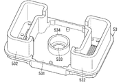
絶縁部材53は、底面部531と、突出部532とを備えている。底面部531の略中央には、可動軸25が挿通される挿入孔533が形成されている。絶縁部材53は、セラミックや合成樹脂などの絶縁性材料から上面が開口した略中空直方体状に形成され、周壁の上端側がケース51の周壁の内面に当接する。これにより、絶縁部材53は、ケース51の開口部において、固定接点211と可動接点221との間で発生するアークを、ケース51と連結体52との接合部から絶縁する。 The insulating member 53 includes a bottom surface portion 531 and a protruding portion 532. An insertion hole 533 through which the movable shaft 25 is inserted is formed at substantially the center of the bottom surface portion 531. The insulating member 53 is formed of a substantially hollow rectangular parallelepiped having an open upper surface from an insulating material such as ceramic or synthetic resin, and the upper end side of the peripheral wall abuts on the inner surface of the peripheral wall of the case 51. As a result, the insulating member 53 insulates the arc generated between the fixed contact 211 and the movable contact 221 from the joint portion between the case 51 and the connecting body 52 at the opening of the case 51.

ところで、本実施形態の接点装置2では、図4に示すように、ばね受け部24は、可動接触子22の一対の固定接点211側とは反対側に配置されている。そして、ばね受け部24は、基部241と、位置決め凸部242と、突出部243と、隔壁244(第1の隔壁)とを備えている。隔壁244は、可動軸25の周囲に設けられている。より詳細には、隔壁244は、例えば円筒状に形成されており、可動軸25の軸方向に沿って基部241から絶縁部材53に向かって延びて設けられている。そして、本実施形態の隔壁244は、可動接触子22および可動軸25と連動する。ここで、連動とは、ある部材が動くと他の部材も同時に動くことだけでなく、ある部材が動くと少しの時間遅れがあった後に他の部材が動くことも含む。なお、隔壁244は、可動接触子22のみと連動してもよいし、可動軸25のみと連動してもよい。 By the way, in the contact device 2 of the present embodiment, as shown in FIG. 4, the spring receiving portion 24 is arranged on the side opposite to the pair of fixed contact 211 side of the movable contact 22. The spring receiving portion 24 includes a base portion 241, a positioning convex portion 242, a protruding portion 243, and a partition wall 244 (first partition wall). The partition wall 244 is provided around the movable shaft 25. More specifically, the partition wall 244 is formed in a cylindrical shape, for example, and is provided extending from the base portion 241 toward the insulating member 53 along the axial direction of the movable shaft 25. Then, the partition wall 244 of the present embodiment is interlocked with the movable contactor 22 and the movable shaft 25. Here, interlocking includes not only that when a certain member moves, other members move at the same time, but also that when a certain member moves, another member moves after a slight time delay. The partition wall 244 may be interlocked only with the movable contact 22 or may be interlocked with only the movable shaft 25.

上記のような隔壁244が設けられていることによって、固定接点211と可動接触子22との接離によって発生した異物が挿入孔533に侵入することを低減できる。 By providing the partition wall 244 as described above, it is possible to reduce the invasion of foreign matter generated by the contact and separation between the fixed contact 211 and the movable contact 22 into the insertion hole 533.

続いて、本実施形態に係る接点装置2の動作について説明する。まず、駆動装置3によって可動軸25が上方へ変位すると、可動軸25の変位に伴って可動軸25に接続されたばね受け部24および接触子ホルダ28が上方へ変位する。ばね受け部24および接触子ホルダ28の変位に伴って、可動接触子22が上方へ移動する。そして、可動接触子22が、一対の固定接点211に当接して接点間が導通する。 Subsequently, the operation of the contact device 2 according to the present embodiment will be described. First, when the movable shaft 25 is displaced upward by the drive device 3, the spring receiving portion 24 and the contactor holder 28 connected to the movable shaft 25 are displaced upward along with the displacement of the movable shaft 25. The movable contact 22 moves upward as the spring receiving portion 24 and the contact holder 28 are displaced. Then, the movable contact 22 comes into contact with the pair of fixed contacts 211, and the contacts become conductive.

次に、駆動装置3について詳細を説明する。 Next, the drive device 3 will be described in detail.

駆動装置3は、電磁石ブロックであり、可動接触子22が一対の固定接点211に接離するように可動軸25を駆動する。 The drive device 3 is an electromagnet block, and drives the movable shaft 25 so that the movable contact 22 comes into contact with and separates from the pair of fixed contacts 211.

駆動装置3は、励磁巻線31と、コイルボビン32と、固定鉄心33と、可動鉄心34と、継鉄35と、復帰ばね36と、円筒部材37と、ブッシュ38とを備えている。また、駆動装置3は、励磁巻線31の両端がそれぞれ接続される一対のコイル端子を備えている。 The drive device 3 includes an exciting winding 31, a coil bobbin 32, a fixed iron core 33, a movable iron core 34, a joint iron 35, a return spring 36, a cylindrical member 37, and a bush 38. Further, the drive device 3 includes a pair of coil terminals to which both ends of the exciting winding 31 are connected to each other.

コイルボビン32は、樹脂材料によって上端および下端に鍔部321,322が形成された略円筒状に形成され、鍔部321,322間の円筒部323に励磁巻線31が巻回されている。また、円筒部323の下端側の内径は、上端側の内径よりも拡径されている。 The coil bobbin 32 is formed in a substantially cylindrical shape in which flange portions 321 and 322 are formed at the upper and lower ends by a resin material, and an exciting winding 31 is wound around a cylindrical portion 323 between the collar portions 321 and 322. Further, the inner diameter of the cylindrical portion 323 on the lower end side is larger than the inner diameter on the upper end side.

励磁巻線31は、コイルボビン32の鍔部321に設けられる一対の端子部に端部が各々接続され、端子部に接続されるリード線を介して一対のコイル端子とそれぞれ接続されている。コイル端子は、銅などの導電性材料から形成され、半田などによってリード線と接続されている。 The end of the exciting winding 31 is connected to a pair of terminal portions provided on the flange portion 321 of the coil bobbin 32, and each of the exciting winding 31 is connected to the pair of coil terminals via a lead wire connected to the terminal portion. The coil terminal is formed of a conductive material such as copper, and is connected to the lead wire by solder or the like.

固定鉄心33は、磁性材料によって略円柱状に形成されており、コイルボビン32内に配置されて固定されている。より詳細には、固定鉄心33は、コイルボビン32の円筒部323に収納されている円筒部材37内に設けられている。 The fixed iron core 33 is formed in a substantially columnar shape by a magnetic material, and is arranged and fixed in the coil bobbin 32. More specifically, the fixed iron core 33 is provided in the cylindrical member 37 housed in the cylindrical portion 323 of the coil bobbin 32.

可動鉄心34は、磁性材料によって略円筒状に形成されており、軸方向において固定鉄心33と対向するようにコイルボビン32内に配置されている。より詳細には、可動鉄心34は、円筒部材37内に設けられている。可動鉄心34は、可動軸25と固定され、励磁巻線31への通電に応じて上下方向に移動する。より詳細には、励磁巻線31が通電されると、可動鉄心34は上方向に移動する。一方、励磁巻線31への通電が遮断されると、可動鉄心34は下方向に移動する。 The movable iron core 34 is formed in a substantially cylindrical shape by a magnetic material, and is arranged in the coil bobbin 32 so as to face the fixed iron core 33 in the axial direction. More specifically, the movable iron core 34 is provided in the cylindrical member 37. The movable iron core 34 is fixed to the movable shaft 25 and moves in the vertical direction in response to the energization of the exciting winding 31. More specifically, when the exciting winding 31 is energized, the movable iron core 34 moves upward. On the other hand, when the energization of the exciting winding 31 is cut off, the movable iron core 34 moves downward.

継鉄35は、第1の継鉄板351と、第2の継鉄板352と、一対の第3の継鉄板353とを備えている。第1の継鉄板351は、コイルボビン32の上端側に設けられている。第2の継鉄板352は、コイルボビン32の下端側に設けられている。一対の第3の継鉄板353は、第2の継鉄板352の左右両端から第1の継鉄板351側へ延びて設けられている。第1の継鉄板351は、略矩形板状に形成されている。第1の継鉄板351の上面側略中央には、挿通孔354が形成されている。挿通孔354には、固定鉄心33の上端部が挿通されている。 The joint iron 35 includes a first joint iron plate 351 and a second joint iron plate 352, and a pair of third joint iron plates 353. The first joint iron plate 351 is provided on the upper end side of the coil bobbin 32. The second joint iron plate 352 is provided on the lower end side of the coil bobbin 32. The pair of third joint iron plates 353 are provided so as to extend from the left and right ends of the second joint iron plate 352 toward the first joint iron plate 351 side. The first joint iron plate 351 is formed in a substantially rectangular plate shape. An insertion hole 354 is formed in the substantially center of the upper surface side of the first joint iron plate 351. The upper end of the fixed iron core 33 is inserted into the insertion hole 354.

復帰ばね36は、固定鉄心33の貫通孔331の下部および可動鉄心34の貫通孔341の上部に挿入されている。復帰ばね36は、固定鉄心33と可動鉄心34との間に圧縮状態で設けられており、可動鉄心34を下方へ弾性付勢する。 The return spring 36 is inserted into the lower part of the through hole 331 of the fixed iron core 33 and the upper part of the through hole 341 of the movable iron core 34. The return spring 36 is provided between the fixed iron core 33 and the movable iron core 34 in a compressed state, and elastically biases the movable iron core 34 downward.

円筒部材37は、有底円筒状に形成されており、コイルボビン32の円筒部323に収納されている。円筒部材37の上端には鍔部371が形成されている。鍔部371がコイルボビン32の鍔部321と第1の継鉄板351との間に位置する。ここで、円筒部材37の円筒部372内の下端側には、可動鉄心34が設けられている。さらに、円筒部372内には、固定鉄心33が設けられている。 The cylindrical member 37 is formed in a bottomed cylindrical shape, and is housed in the cylindrical portion 323 of the coil bobbin 32. A collar portion 371 is formed at the upper end of the cylindrical member 37. The flange portion 371 is located between the flange portion 321 of the coil bobbin 32 and the first joint iron plate 351. Here, a movable iron core 34 is provided on the lower end side of the cylindrical portion 372 of the cylindrical member 37. Further, a fixed iron core 33 is provided in the cylindrical portion 372.

ブッシュ38は、磁性材料によって円筒状に形成されている。ブッシュ38は、コイルボビン32における下端側の内周面と円筒部材37の外周面との間に形成される隙間部分に嵌合されている。ブッシュ38は、第1〜3の継鉄板351〜353と固定鉄心33と可動鉄心34とともに磁気回路を形成している。 The bush 38 is formed in a cylindrical shape by a magnetic material. The bush 38 is fitted in a gap portion formed between the inner peripheral surface on the lower end side of the coil bobbin 32 and the outer peripheral surface of the cylindrical member 37. The bush 38 forms a magnetic circuit together with the first to third joint iron plates 351 to 353, the fixed iron core 33, and the movable iron core 34.

次に、ハウジング4について詳細を説明する。 Next, the housing 4 will be described in detail.

ハウジング4は、樹脂材料によって略矩形箱状に形成されており、上面が開口した中空箱型のハウジング本体41と、ハウジング本体41の開口に覆設する中空箱型のカバー42とから構成されている。 The housing 4 is formed of a resin material in a substantially rectangular box shape, and is composed of a hollow box-shaped housing body 41 having an open upper surface and a hollow box-shaped cover 42 covering the opening of the housing body 41. There is.

ハウジング本体41は、図2に示すように、左右側壁の前端に、電磁継電器1を取付面にねじ止めによって固定する際に用いられる挿通孔が形成された一対の突部411が設けられている。また、図1に示すように、ハウジング本体41の上端側の開口周縁には段部412が形成されており、上端は下端側に比べて内径が大きくなっている。 As shown in FIG. 2, the housing main body 41 is provided with a pair of protrusions 411 having insertion holes formed at the front ends of the left and right side walls for fixing the electromagnetic relay 1 to the mounting surface by screwing. .. Further, as shown in FIG. 1, a step portion 412 is formed on the peripheral edge of the opening on the upper end side of the housing main body 41, and the upper end has an inner diameter larger than that on the lower end side.

カバー42は、下面が開口した中空箱型に形成されている。カバー42の上面部421には、上面部421を左右に略2分割する仕切り部422が形成されている。仕切り部422によって2分割された上面部421には、それぞれ固定端子21が挿通する一対の挿通孔423が形成されている。 The cover 42 is formed in a hollow box shape with an open lower surface. The upper surface portion 421 of the cover 42 is formed with a partition portion 422 that substantially divides the upper surface portion 421 into two left and right. A pair of insertion holes 423 through which the fixed terminals 21 are inserted are formed in the upper surface portion 421 divided into two by the partition portion 422.

また、ハウジング4に接点装置2および駆動装置3が収納される際には、継鉄35の第2の継鉄板352とハウジング本体41の底面部413との間に下側クッションゴム43が介装される。そして、ケース51とカバー42との間には、固定端子21が挿通する挿通孔441が形成された上側クッションゴム44が介装されている。 Further, when the contact device 2 and the drive device 3 are housed in the housing 4, a lower cushion rubber 43 is interposed between the second joint iron plate 352 of the joint iron 35 and the bottom surface portion 413 of the housing main body 41. Will be done. An upper cushion rubber 44 having an insertion hole 441 through which the fixed terminal 21 is inserted is interposed between the case 51 and the cover 42.

上記構成からなる電磁継電器1は、復帰ばね36の付勢力によって可動鉄心34が下方へ摺動し、それに伴って可動軸25も下方へ移動する。これにより、可動接触子22は、調整部26によって下方へ押圧されると調整部26とともに下方へ移動する。そのため、初期状態では可動接点221が固定接点211と離間している。 In the electromagnetic relay 1 having the above configuration, the movable iron core 34 slides downward due to the urging force of the return spring 36, and the movable shaft 25 also moves downward accordingly. As a result, when the movable contactor 22 is pressed downward by the adjusting portion 26, the movable contactor 22 moves downward together with the adjusting portion 26. Therefore, in the initial state, the movable contact 221 is separated from the fixed contact 211.

そして、励磁巻線31が通電され、可動鉄心34が固定鉄心33に吸引されて上方へ摺動すると、可動鉄心34に連結された可動軸25も連動して上方へ移動する。これにより、可動軸25に接続されたばね受け部24(接触子ホルダ28)が固定接点211側へ移動し、接触子ホルダ28の上記移動に伴って可動接触子22も上方へ移動する。そして、可動接点221が固定接点211に当接して接点間が導通する。 Then, when the exciting winding 31 is energized and the movable iron core 34 is attracted to the fixed iron core 33 and slides upward, the movable shaft 25 connected to the movable iron core 34 also moves upward in conjunction with it. As a result, the spring receiving portion 24 (contactor holder 28) connected to the movable shaft 25 moves toward the fixed contact 211 side, and the movable contactor 22 also moves upward with the movement of the contactor holder 28. Then, the movable contact 221 comes into contact with the fixed contact 211, and the contacts become conductive.

また、励磁巻線31への通電がオフされると、復帰ばね36の付勢力によって可動鉄心34が下方へ摺動し、それに伴って可動軸25も下方へ向かって移動する。これにより、ばね受け部24(接触子ホルダ28)も下方へ移動し、接触子ホルダ28の上記移動に伴って可動接触子22も下方へ移動するので、固定接点211と可動接点221とが離間する。 Further, when the energization of the exciting winding 31 is turned off, the movable iron core 34 slides downward due to the urging force of the return spring 36, and the movable shaft 25 also moves downward accordingly. As a result, the spring receiving portion 24 (contactor holder 28) also moves downward, and the movable contactor 22 also moves downward with the movement of the contactor holder 28, so that the fixed contact 211 and the movable contact 221 are separated from each other. do.

なお、本実施形態の電磁継電器1の接点装置2では、一対の可動接点221は、可動接触子22の一部であって、可動接触子22と一体に設けられているが、本実施形態の変形例として、一対の可動接点は、可動接触子22とは別体に設けられていてもよい。このような接点装置2においても、可動軸25の移動によって、可動接触子とは別体に設けられた可動接点が可動接触子22と一体に移動し、可動接点が固定接点211に接離する。 In the contact device 2 of the electromagnetic relay 1 of the present embodiment, the pair of movable contacts 221 are a part of the movable contact 22 and are provided integrally with the movable contact 22. As a modification, the pair of movable contacts may be provided separately from the movable contacts 22. Even in such a contact device 2, due to the movement of the movable shaft 25, the movable contact provided separately from the movable contact moves integrally with the movable contact 22, and the movable contact is brought into contact with and separated from the fixed contact 211. ..

以上説明した本実施形態に係る接点装置2では、可動接触子22が一対の固定接点211に接離する箇所(接点部)すなわち異物の発生個所の近くに隔壁244が設けられている。これにより、簡単な構成でありながら、効率的に可動軸25の挿入孔533への異物の侵入を低減させることができる。すなわち、異物が挿入孔533を介して駆動装置3に侵入することを低減できる。 In the contact device 2 according to the present embodiment described above, a partition wall 244 is provided near a portion (contact portion) where the movable contact 22 comes into contact with and separates from the pair of fixed contacts 211, that is, a location where foreign matter is generated. As a result, it is possible to efficiently reduce the intrusion of foreign matter into the insertion hole 533 of the movable shaft 25, despite the simple configuration. That is, it is possible to reduce the invasion of foreign matter into the drive device 3 through the insertion hole 533.

(実施形態2)
実施形態2に係る接点装置2は、図5に示すように、絶縁部材53に隔壁534が設けられている点で、実施形態1に係る接点装置2(図1参照)と相違する。なお、実施形態1の電磁継電器1(図1参照)と同様の構成要素については、同一の符号を付して説明を省略する。
(Embodiment 2)
The contact device 2 according to the second embodiment is different from the contact device 2 according to the first embodiment (see FIG. 1) in that a partition wall 534 is provided on the insulating member 53 as shown in FIG. The same components as those of the electromagnetic relay 1 (see FIG. 1) of the first embodiment are designated by the same reference numerals, and the description thereof will be omitted.

本実施形態の絶縁部材53は、可動軸25が挿入される挿入孔533の周囲に設けられた隔壁534(第2の隔壁)を備えている。すなわち、絶縁部材53は、底面部531と、突出部532と、隔壁534とを備えている。隔壁534は、可動軸25の軸方向に沿って底面部531からばね受け部24(第1の隔壁部材)に向かって延びて設けられている。そして、絶縁部材53は、可動軸25の軸方向(上下方向)においてばね受け部24と対向している。なお、実施形態1の絶縁部材53(図1参照)と同様の機能については説明を省略する。 The insulating member 53 of the present embodiment includes a partition wall 534 (second partition wall) provided around the insertion hole 533 into which the movable shaft 25 is inserted. That is, the insulating member 53 includes a bottom surface portion 531, a protruding portion 532, and a partition wall 534. The partition wall 534 is provided so as to extend from the bottom surface portion 531 toward the spring receiving portion 24 (first partition wall member) along the axial direction of the movable shaft 25. The insulating member 53 faces the spring receiving portion 24 in the axial direction (vertical direction) of the movable shaft 25. The same function as the insulating member 53 (see FIG. 1) of the first embodiment will not be described.

以上説明した本実施形態に係る接点装置2では、可動接触子22が一対の固定接点211に接離する箇所(接点部)すなわち異物の発生個所の近くに隔壁244,534が設けられている。これにより、簡単な構成でありながら、効率的に可動軸25の挿入孔への異物の侵入を低減させることができる。 In the contact device 2 according to the present embodiment described above, partition walls 244 and 534 are provided near a portion (contact portion) where the movable contact 22 comes into contact with and separates from the pair of fixed contacts 211, that is, a location where foreign matter is generated. As a result, it is possible to efficiently reduce the intrusion of foreign matter into the insertion hole of the movable shaft 25, despite the simple configuration.

(実施形態3)
実施形態3に係る接点装置2は、図6に示すように、ばね受け部24の隔壁244と絶縁部材53の隔壁534とが重なり合う点で、実施形態2に係る接点装置2(図5参照)と相違する。なお、実施形態2の電磁継電器1(図5参照)と同様の構成要素については、同一の符号を付して説明を省略する。
(Embodiment 3)
As shown in FIG. 6, the contact device 2 according to the third embodiment is a contact device 2 according to the second embodiment (see FIG. 5) in that the partition wall 244 of the spring receiving portion 24 and the partition wall 534 of the insulating member 53 overlap each other. Is different from. The same components as those of the electromagnetic relay 1 (see FIG. 5) of the second embodiment are designated by the same reference numerals, and the description thereof will be omitted.

本実施形態におけるばね受け部24(第1の隔壁部材)の隔壁244(第1の隔壁)および絶縁部材53(第2の隔壁部材)の隔壁534(第2の隔壁)は、可動軸25の軸方向と直交する方向において重なり合うように設けられている。より詳細に説明すると、図7に示すように、絶縁部材53は、底面部531と、突出部532と、隔壁534とを備えている。隔壁534は、可動軸25の軸方向に沿って底面部531からばね受け部24に向かって延びて設けられている。そして、隔壁244および隔壁534は、可動軸25の軸方向と直交する方向において重なり合っている。なお、実施形態2のばね受け部24および絶縁部材53(図5参照)と同様の機能については説明を省略する。 The partition wall 244 (first partition wall) of the spring receiving portion 24 (first partition wall member) and the partition wall 534 (second partition wall) of the insulating member 53 (second partition wall member) in the present embodiment are the movable shaft 25. It is provided so as to overlap in a direction orthogonal to the axial direction. More specifically, as shown in FIG. 7, the insulating member 53 includes a bottom surface portion 531, a protruding portion 532, and a partition wall 534. The partition wall 534 is provided so as to extend from the bottom surface portion 531 toward the spring receiving portion 24 along the axial direction of the movable shaft 25. The partition wall 244 and the partition wall 534 overlap each other in a direction orthogonal to the axial direction of the movable shaft 25. The same functions as the spring receiving portion 24 and the insulating member 53 (see FIG. 5) of the second embodiment will not be described.

以上説明した本実施形態に係る接点装置2では、ばね受け部24の隔壁244(第1の隔壁)および絶縁部材53の隔壁534(第2の隔壁)が重なり合うことによって、異物の移動経路が長くなり、さらに異物の侵入を低減させることができる。 In the contact device 2 according to the present embodiment described above, the partition wall 244 (first partition wall) of the spring receiving portion 24 and the partition wall 534 (second partition wall) of the insulating member 53 overlap each other, so that the movement path of the foreign matter becomes long. Therefore, the invasion of foreign matter can be further reduced.

(実施形態4)
実施形態4に係る接点装置2は、図8,9に示すように、複数の隔壁244,534,535が互いに重なり合う点で、実施形態3に係る接点装置2(図6参照)と相違する。なお、実施形態3の電磁継電器1(図6参照)と同様の構成要素については、同一の符号を付して説明を省略する。
(Embodiment 4)
As shown in FIGS. 8 and 9, the contact device 2 according to the fourth embodiment is different from the contact device 2 (see FIG. 6) according to the third embodiment in that a plurality of partition walls 244, 534 and 535 overlap each other. The same components as those of the electromagnetic relay 1 (see FIG. 6) of the third embodiment are designated by the same reference numerals, and the description thereof will be omitted.

本実施形態の絶縁部材53の隔壁534,535は、複数個同心円状に可動軸25の周囲に設けられている。すなわち、図10に示すように、絶縁部材53は、底面部531と、突出部532と、2つの隔壁534,535とを備えている。そして、本実施形態では、隔壁244および隔壁534,535は、可動軸25と直交する方向において互い違いに重なり合う。なお、実施形態1のばね受け部24および絶縁部材53(図6参照)と同様の機能については説明を省略する。 A plurality of partition walls 534 and 535 of the insulating member 53 of the present embodiment are concentrically provided around the movable shaft 25. That is, as shown in FIG. 10, the insulating member 53 includes a bottom surface portion 531 and a protruding portion 532, and two partition walls 534 and 535. Then, in the present embodiment, the partition walls 244 and the partition walls 534 and 535 are alternately overlapped in the direction orthogonal to the movable shaft 25. The same functions as the spring receiving portion 24 and the insulating member 53 (see FIG. 6) of the first embodiment will not be described.

以上説明した本実施形態に係る接点装置2では、ばね受け部24の隔壁244(第1の隔壁)および絶縁部材53の隔壁534,535(第2の隔壁)によって異物の移動経路がラビリンス状になり、さらに異物の侵入を低減させることができる。 In the contact device 2 according to the present embodiment described above, the movement path of the foreign matter is labyrinthed by the partition wall 244 (first partition wall) of the spring receiving portion 24 and the partition walls 534 and 535 (second partition wall) of the insulating member 53. Therefore, the invasion of foreign matter can be further reduced.

なお、絶縁部材53の隔壁ではなく、ばね受け部24の隔壁が複数個同心円状に可動軸25の周囲に設けられていてもよいし、ばね受け部24の隔壁と絶縁部材53の隔壁のいずれもが複数個同心円状に可動軸25の周囲に設けられていてもよい。 A plurality of partition walls of the spring receiving portion 24 may be concentrically provided around the movable shaft 25 instead of the partition wall of the insulating member 53, or either the partition wall of the spring receiving portion 24 or the partition wall of the insulating member 53. A plurality of thighs may be concentrically provided around the movable shaft 25.

(実施形態5)
実施形態5に係る接点装置2は、図11に示すように、対応する隔壁244,534の先端部同士が対向している点で、実施形態2に係る接点装置2(図5参照)と相違する。なお、実施形態2の電磁継電器1(図5参照)と同様の構成要素については、同一の符号を付して説明を省略する。
(Embodiment 5)
As shown in FIG. 11, the contact device 2 according to the fifth embodiment is different from the contact device 2 (see FIG. 5) according to the second embodiment in that the tips of the corresponding partition walls 244 and 534 face each other. do. The same components as those of the electromagnetic relay 1 (see FIG. 5) of the second embodiment are designated by the same reference numerals, and the description thereof will be omitted.

本実施形態の接点装置2では、ばね受け部24の隔壁244(第1の隔壁)の先端部および絶縁部材53の隔壁(第2の隔壁)の先端部は、可動軸25の軸方向において対向している。すなわち、隔壁244と隔壁534とは、同じ半径の円筒である。なお、実施形態2のばね受け部24および絶縁部材53(図5参照)と同様の機能については説明を省略する。 In the contact device 2 of the present embodiment, the tip of the partition wall 244 (first partition wall) of the spring receiving portion 24 and the tip of the partition wall (second partition wall) of the insulating member 53 face each other in the axial direction of the movable shaft 25. doing. That is, the partition wall 244 and the partition wall 534 are cylinders having the same radius. The same functions as the spring receiving portion 24 and the insulating member 53 (see FIG. 5) of the second embodiment will not be described.

以上説明した本実施形態に係る接点装置2では、ばね受け部24の隔壁244(第1の隔壁)と絶縁部材53の隔壁(第2の隔壁)とが可動軸25の軸方向において接触するので、小型化を図ることができる。 In the contact device 2 according to the present embodiment described above, the partition wall 244 (first partition wall) of the spring receiving portion 24 and the partition wall (second partition wall) of the insulating member 53 come into contact with each other in the axial direction of the movable shaft 25. , It is possible to reduce the size.

(実施形態6)
実施形態6に係る接点装置2は、図12に示すように、ばね受け部24の上方と下方とを遮断するように隔壁244が設けられている点で、実施形態1に係る接点装置2(図1参照)と相違する。なお、実施形態1の電磁継電器1(図1参照)と同様の構成要素については、同一の符号を付して説明を省略する。
(Embodiment 6)
As shown in FIG. 12, the contact device 2 according to the sixth embodiment is provided with a partition wall 244 so as to block the upper side and the lower side of the spring receiving portion 24. See FIG. 1). The same components as those of the electromagnetic relay 1 (see FIG. 1) of the first embodiment are designated by the same reference numerals, and the description thereof will be omitted.

本実施形態のばね受け部24では、隔壁244(第1の隔壁)は、可動軸25の軸方向と交差する方向に延びて設けられた延設部を含んでいる。すなわち、隔壁244は、基部側が基部241から可動軸25の軸方向に沿って延びており、先端側が軸方向と交差する方向に延びている。なお、実施形態1のばね受け部24(図1参照)と同様の機能については説明を省略する。 In the spring receiving portion 24 of the present embodiment, the partition wall 244 (first partition wall) includes an extension portion provided so as to extend in a direction intersecting the axial direction of the movable shaft 25. That is, the partition wall 244 extends from the base portion 241 along the axial direction of the movable shaft 25, and the tip end side extends in a direction intersecting the axial direction. The same function as the spring receiving portion 24 (see FIG. 1) of the first embodiment will not be described.

以上説明した本実施形態に係る接点装置2では、周方向に位置する突出部532と隔壁244との間の隙間を小さくすることができるので、異物の移動経路を長くすることができる。 In the contact device 2 according to the present embodiment described above, the gap between the protrusion 532 located in the circumferential direction and the partition wall 244 can be reduced, so that the movement path of the foreign matter can be lengthened.

1 電磁継電器
2 接点装置
211 固定接点
22 可動接触子
24 ばね受け部(第1の隔壁部材)
243 突出部
244 隔壁(第1の隔壁)
25 可動軸
3 駆動装置
53 絶縁部材(第2の隔壁部材)
533 挿入孔
534 隔壁(第1隔壁)
535 隔壁(第2隔壁)
1 Electromagnetic relay 2 Contact device 211 Fixed contact 22 Movable contact 24 Spring receiving part (first partition member)
243 Protruding part 244 partition wall (first partition wall)
25 Movable shaft 3 Drive device 53 Insulation member (second partition member)
533 Insertion hole 534 Septum (1st bulkhead)
535 partition wall (second partition wall)

Claims (9)

固定接点と、
第1軸に沿って延び、前記固定接点に対向配置された可動接点を含む可動接触子と、
前記第1軸に直交する第2軸に沿って延び、駆動装置の通電状態に応じて、前記可動接触子を前記第2軸に沿って移動させて前記可動接点を前記固定接点に接離させるように配置された可動軸と、
前記可動接触子に対して前記固定接点とは反対側に設けられ、前記可動接点を前記固定接点に向けて付勢する接圧ばねと、
前記可動軸の端部の周囲に設けられ、前記第2軸に沿って第1地点から第2地点まで円筒形状に突出する突出部を含む隔壁部材と、
前記可動軸の周囲に設けられ、前記第2軸に沿って第3地点から第4地点まで突出する第1隔壁と、
前記第2軸に沿って第5地点から第6地点まで突出する第2隔壁と、
を備え、
前記第2軸に沿った方向において、前記隔壁部材の前記突出部の前記第1地点と前記第1隔壁の前記第3地点とは互いに異なる位置であり、
前記第2軸に沿った方向において、前記隔壁部材の前記突出部の前記第2地点と前記第1隔壁の前記第4地点とは互いに異なる位置であり、
前記突出部の外径は、前記接圧ばねの外径よりも小さく、
前記第1隔壁は、円筒形状であり、
前記第1隔壁の内径は、前記突出部の外径よりも大きく、
少なくとも前記可動接点が前記固定接点から開離しているとき、前記突出部は、前記第2軸と直交する方向において前記第1隔壁と互いに重なり合う、
電磁継電器。
With fixed contacts
A movable contact that extends along the first axis and includes a movable contact that is arranged to face the fixed contact.
It extends along a second axis orthogonal to the first axis, and moves the movable contact along the second axis according to the energized state of the drive device to bring the movable contact into contact with the fixed contact. Movable shafts arranged so that
A pressure spring provided on the side opposite to the fixed contact with respect to the movable contact and urging the movable contact toward the fixed contact.
A partition wall member provided around the end of the movable shaft and including a protruding portion that protrudes in a cylindrical shape from a first point to a second point along the second axis.
A first partition wall provided around the movable shaft and protruding from a third point to a fourth point along the second shaft.
A second partition wall protruding from the fifth point to the sixth point along the second axis,
With
In the direction along the second axis, the first point of the protrusion of the partition member and the third point of the first partition are different from each other.
In the direction along the second axis, the second point of the protrusion of the partition member and the fourth point of the first partition are different from each other.
The outer diameter of the protrusion, rather smaller than the outer diameter of the contact pressure spring,
The first partition wall has a cylindrical shape and has a cylindrical shape.
The inner diameter of the first partition wall is larger than the outer diameter of the protruding portion.
At least when the movable contact is separated from the fixed contact, the protrusion overlaps with the first bulkhead in a direction orthogonal to the second axis.
Electromagnetic relay.
前記隔壁部材は、絶縁性材料から構成される、
請求項1に記載の電磁継電器。
The partition member is made of an insulating material.
The electromagnetic relay according to claim 1.
前記第1隔壁は、絶縁性材料から構成される、
請求項1または請求項2に記載の電磁継電器。
The first partition wall is made of an insulating material.
The electromagnetic relay according to claim 1 or 2.
前記第2隔壁は、前記第1隔壁の周囲に設けられており、 The second partition wall is provided around the first partition wall, and is provided around the first partition wall.
前記駆動装置は、前記可動軸の少なくとも一部を取り囲むように配置され、且つ、 The drive device is arranged so as to surround at least a part of the movable shaft, and
前記第1隔壁と前記第2隔壁は、前記駆動装置の前記可動接触子側の上面の上方に配置される、 The first partition wall and the second partition wall are arranged above the upper surface of the drive device on the movable contact side.
請求項1に記載の電磁継電器。 The electromagnetic relay according to claim 1.
前記駆動装置は、円筒部を有するコイルボビンと、前記円筒部に巻回された励磁巻線と、前記コイルボビンより前記可動接触子側に配置される継鉄板と、を有する、 The drive device has a coil bobbin having a cylindrical portion, an exciting winding wound around the cylindrical portion, and a joint iron plate arranged on the movable contact side of the coil bobbin.
請求項1または請求項4に記載の電磁継電器。 The electromagnetic relay according to claim 1 or 4.
前記第2軸に沿って見たとき、前記突出部と前記第1隔壁と前記第2隔壁は、前記可動軸と同軸的に設けられた、 When viewed along the second axis, the protrusion, the first partition wall, and the second partition wall are provided coaxially with the movable axis.
請求項1または請求項4に記載の電磁継電器。 The electromagnetic relay according to claim 1 or 4.
前記第2隔壁は、円筒形状である、 The second partition wall has a cylindrical shape.
請求項1に記載の電磁継電器。 The electromagnetic relay according to claim 1.
前記突出部と前記第1隔壁と前記第2隔壁は、ラビリンス状に設けられている、 The protruding portion, the first partition wall, and the second partition wall are provided in a labyrinth shape.
請求項1に記載の電磁継電器。 The electromagnetic relay according to claim 1.
前記隔壁部材は、第3隔壁を含み、 The partition member includes a third partition member.
前記第3隔壁と前記第1隔壁とは、同じ半径の円筒である、 The third partition wall and the first partition wall are cylinders having the same radius.
請求項1に記載の電磁継電器。 The electromagnetic relay according to claim 1.
JP2020018304A 2019-06-26 2020-02-05 Electromagnetic relay Active JP6945171B2 (en)

Priority Applications (2)

Application Number Priority Date Filing Date Title
JP2020018304A JP6945171B2 (en) 2019-06-26 2020-02-05 Electromagnetic relay
JP2021104110A JP7178596B2 (en) 2020-02-05 2021-06-23 electromagnetic relay

Applications Claiming Priority (2)

Application Number Priority Date Filing Date Title
JP2019118295A JP6667150B2 (en) 2019-06-26 2019-06-26 Electromagnetic relay
JP2020018304A JP6945171B2 (en) 2019-06-26 2020-02-05 Electromagnetic relay

Related Parent Applications (1)

Application Number Title Priority Date Filing Date
JP2019118295A Division JP6667150B2 (en) 2019-06-26 2019-06-26 Electromagnetic relay

Related Child Applications (1)

Application Number Title Priority Date Filing Date
JP2021104110A Division JP7178596B2 (en) 2020-02-05 2021-06-23 electromagnetic relay

Publications (2)

Publication Number Publication Date
JP2020074333A JP2020074333A (en) 2020-05-14
JP6945171B2 true JP6945171B2 (en) 2021-10-06

Family

ID=70610231

Family Applications (2)

Application Number Title Priority Date Filing Date
JP2020018304A Active JP6945171B2 (en) 2019-06-26 2020-02-05 Electromagnetic relay
JP2021104110A Active JP7178596B2 (en) 2020-02-05 2021-06-23 electromagnetic relay

Family Applications After (1)

Application Number Title Priority Date Filing Date
JP2021104110A Active JP7178596B2 (en) 2020-02-05 2021-06-23 electromagnetic relay

Country Status (1)

Country Link
JP (2) JP6945171B2 (en)

Families Citing this family (1)

* Cited by examiner, † Cited by third party
Publication number Priority date Publication date Assignee Title
JP2023088604A (en) * 2021-12-15 2023-06-27 オムロン株式会社 electromagnetic relay

Family Cites Families (7)

* Cited by examiner, † Cited by third party
Publication number Priority date Publication date Assignee Title
JPS5917522U (en) * 1982-07-23 1984-02-02 本田技研工業株式会社 switch device
JPH0625859Y2 (en) * 1988-02-03 1994-07-06 矢崎総業株式会社 Push button switch
JP2500202Y2 (en) * 1989-12-26 1996-06-05 東芝ホームテクノ株式会社 Louver device
JP4600499B2 (en) * 2008-03-19 2010-12-15 パナソニック電工株式会社 Contact device
JP5131219B2 (en) * 2009-02-02 2013-01-30 アンデン株式会社 Electromagnetic relay
EP2549498A4 (en) * 2010-03-15 2014-08-13 Omron Tateisi Electronics Co Contact switching device
JP2012199120A (en) * 2011-03-22 2012-10-18 Panasonic Corp Contact device

Also Published As

Publication number Publication date
JP2020074333A (en) 2020-05-14
JP7178596B2 (en) 2022-11-28
JP2021144957A (en) 2021-09-24

Similar Documents

Publication Publication Date Title
CN111211011B (en) Electromagnetic relay
CN106057584B (en) Contact device and electromagnetic relay
JP5938745B2 (en) Contact device and electromagnetic relay equipped with the contact device
WO2020170900A1 (en) Relay
JP6945171B2 (en) Electromagnetic relay
JP4586861B2 (en) Electromagnetic relay
JP6726869B2 (en) Contact device and electromagnetic relay
JP4645659B2 (en) Electromagnetic relay
JP6667150B2 (en) Electromagnetic relay
JP6948627B2 (en) Electromagnetic relay and base
US20200279708A1 (en) Contact device and electromagnetic relay equipped with contact device
JP6685024B2 (en) Electromagnetic relay
JP2017195097A (en) Electromagnetic relay
JP7380028B2 (en) relay
US11908650B2 (en) Electromagnetic relay
US20240136133A1 (en) Electromagnetic relay
JP5336271B2 (en) Contact device
JP6751907B2 (en) Coil bobbins, coil devices and electromagnetic relays
JP2018181655A (en) Contact arrangement, and magnetic relay
JP2018142502A (en) Electromagnetic relay

Legal Events

Date Code Title Description
A621 Written request for application examination

Free format text: JAPANESE INTERMEDIATE CODE: A621

Effective date: 20200205

A977 Report on retrieval

Free format text: JAPANESE INTERMEDIATE CODE: A971007

Effective date: 20201110

A131 Notification of reasons for refusal

Free format text: JAPANESE INTERMEDIATE CODE: A131

Effective date: 20201117

A521 Written amendment

Free format text: JAPANESE INTERMEDIATE CODE: A523

Effective date: 20210118

A02 Decision of refusal

Free format text: JAPANESE INTERMEDIATE CODE: A02

Effective date: 20210323

A521 Written amendment

Free format text: JAPANESE INTERMEDIATE CODE: A523

Effective date: 20210623

C60 Trial request (containing other claim documents, opposition documents)

Free format text: JAPANESE INTERMEDIATE CODE: C60

Effective date: 20210623

A911 Transfer to examiner for re-examination before appeal (zenchi)

Free format text: JAPANESE INTERMEDIATE CODE: A911

Effective date: 20210701

C21 Notice of transfer of a case for reconsideration by examiners before appeal proceedings

Free format text: JAPANESE INTERMEDIATE CODE: C21

Effective date: 20210706

TRDD Decision of grant or rejection written
A01 Written decision to grant a patent or to grant a registration (utility model)

Free format text: JAPANESE INTERMEDIATE CODE: A01

Effective date: 20210803

A61 First payment of annual fees (during grant procedure)

Free format text: JAPANESE INTERMEDIATE CODE: A61

Effective date: 20210827

R151 Written notification of patent or utility model registration

Ref document number: 6945171

Country of ref document: JP

Free format text: JAPANESE INTERMEDIATE CODE: R151