WO2013150869A1 - フローセル、これを用いた分析装置、及び分析方法 - Google Patents
フローセル、これを用いた分析装置、及び分析方法 Download PDFInfo
- Publication number
- WO2013150869A1 WO2013150869A1 PCT/JP2013/056895 JP2013056895W WO2013150869A1 WO 2013150869 A1 WO2013150869 A1 WO 2013150869A1 JP 2013056895 W JP2013056895 W JP 2013056895W WO 2013150869 A1 WO2013150869 A1 WO 2013150869A1
- Authority
- WO
- WIPO (PCT)
- Prior art keywords
- slit
- flow cell
- biological substance
- capture
- bacteria
- Prior art date
- Legal status (The legal status is an assumption and is not a legal conclusion. Google has not performed a legal analysis and makes no representation as to the accuracy of the status listed.)
- Ceased
Links
Images




Classifications
-
- G—PHYSICS
- G01—MEASURING; TESTING
- G01N—INVESTIGATING OR ANALYSING MATERIALS BY DETERMINING THEIR CHEMICAL OR PHYSICAL PROPERTIES
- G01N15/00—Investigating characteristics of particles; Investigating permeability, pore-volume or surface-area of porous materials
- G01N15/10—Investigating individual particles
- G01N15/14—Optical investigation techniques, e.g. flow cytometry
- G01N15/1404—Handling flow, e.g. hydrodynamic focusing
-
- B—PERFORMING OPERATIONS; TRANSPORTING
- B01—PHYSICAL OR CHEMICAL PROCESSES OR APPARATUS IN GENERAL
- B01L—CHEMICAL OR PHYSICAL LABORATORY APPARATUS FOR GENERAL USE
- B01L3/00—Containers or dishes for laboratory use, e.g. laboratory glassware; Droppers
- B01L3/50—Containers for the purpose of retaining a material to be analysed, e.g. test tubes
- B01L3/502—Containers for the purpose of retaining a material to be analysed, e.g. test tubes with fluid transport, e.g. in multi-compartment structures
- B01L3/5027—Containers for the purpose of retaining a material to be analysed, e.g. test tubes with fluid transport, e.g. in multi-compartment structures by integrated microfluidic structures, i.e. dimensions of channels and chambers are such that surface tension forces are important, e.g. lab-on-a-chip
- B01L3/502753—Containers for the purpose of retaining a material to be analysed, e.g. test tubes with fluid transport, e.g. in multi-compartment structures by integrated microfluidic structures, i.e. dimensions of channels and chambers are such that surface tension forces are important, e.g. lab-on-a-chip characterised by bulk separation arrangements on lab-on-a-chip devices, e.g. for filtration or centrifugation
-
- C—CHEMISTRY; METALLURGY
- C12—BIOCHEMISTRY; BEER; SPIRITS; WINE; VINEGAR; MICROBIOLOGY; ENZYMOLOGY; MUTATION OR GENETIC ENGINEERING
- C12M—APPARATUS FOR ENZYMOLOGY OR MICROBIOLOGY; APPARATUS FOR CULTURING MICROORGANISMS FOR PRODUCING BIOMASS, FOR GROWING CELLS OR FOR OBTAINING FERMENTATION OR METABOLIC PRODUCTS, i.e. BIOREACTORS OR FERMENTERS
- C12M41/00—Means for regulation, monitoring, measurement or control, e.g. flow regulation
- C12M41/30—Means for regulation, monitoring, measurement or control, e.g. flow regulation of concentration
- C12M41/36—Means for regulation, monitoring, measurement or control, e.g. flow regulation of concentration of biomass, e.g. colony counters or by turbidity measurements
-
- C—CHEMISTRY; METALLURGY
- C12—BIOCHEMISTRY; BEER; SPIRITS; WINE; VINEGAR; MICROBIOLOGY; ENZYMOLOGY; MUTATION OR GENETIC ENGINEERING
- C12M—APPARATUS FOR ENZYMOLOGY OR MICROBIOLOGY; APPARATUS FOR CULTURING MICROORGANISMS FOR PRODUCING BIOMASS, FOR GROWING CELLS OR FOR OBTAINING FERMENTATION OR METABOLIC PRODUCTS, i.e. BIOREACTORS OR FERMENTERS
- C12M47/00—Means for after-treatment of the produced biomass or of the fermentation or metabolic products, e.g. storage of biomass
- C12M47/02—Separating microorganisms from the culture medium; Concentration of biomass
-
- G—PHYSICS
- G01—MEASURING; TESTING
- G01N—INVESTIGATING OR ANALYSING MATERIALS BY DETERMINING THEIR CHEMICAL OR PHYSICAL PROPERTIES
- G01N33/00—Investigating or analysing materials by specific methods not covered by groups G01N1/00 - G01N31/00
- G01N33/48—Biological material, e.g. blood, urine; Haemocytometers
- G01N33/483—Physical analysis of biological material
- G01N33/4833—Physical analysis of biological material of solid biological material, e.g. tissue samples, cell cultures
-
- B—PERFORMING OPERATIONS; TRANSPORTING
- B01—PHYSICAL OR CHEMICAL PROCESSES OR APPARATUS IN GENERAL
- B01L—CHEMICAL OR PHYSICAL LABORATORY APPARATUS FOR GENERAL USE
- B01L2300/00—Additional constructional details
- B01L2300/08—Geometry, shape and general structure
- B01L2300/0809—Geometry, shape and general structure rectangular shaped
- B01L2300/0816—Cards, e.g. flat sample carriers usually with flow in two horizontal directions
-
- B—PERFORMING OPERATIONS; TRANSPORTING
- B01—PHYSICAL OR CHEMICAL PROCESSES OR APPARATUS IN GENERAL
- B01L—CHEMICAL OR PHYSICAL LABORATORY APPARATUS FOR GENERAL USE
- B01L2300/00—Additional constructional details
- B01L2300/08—Geometry, shape and general structure
- B01L2300/0861—Configuration of multiple channels and/or chambers in a single devices
- B01L2300/0877—Flow chambers
-
- B—PERFORMING OPERATIONS; TRANSPORTING
- B01—PHYSICAL OR CHEMICAL PROCESSES OR APPARATUS IN GENERAL
- B01L—CHEMICAL OR PHYSICAL LABORATORY APPARATUS FOR GENERAL USE
- B01L2400/00—Moving or stopping fluids
- B01L2400/04—Moving fluids with specific forces or mechanical means
- B01L2400/0475—Moving fluids with specific forces or mechanical means specific mechanical means and fluid pressure
- B01L2400/0487—Moving fluids with specific forces or mechanical means specific mechanical means and fluid pressure fluid pressure, pneumatics
-
- B—PERFORMING OPERATIONS; TRANSPORTING
- B01—PHYSICAL OR CHEMICAL PROCESSES OR APPARATUS IN GENERAL
- B01L—CHEMICAL OR PHYSICAL LABORATORY APPARATUS FOR GENERAL USE
- B01L2400/00—Moving or stopping fluids
- B01L2400/08—Regulating or influencing the flow resistance
- B01L2400/084—Passive control of flow resistance
- B01L2400/086—Passive control of flow resistance using baffles or other fixed flow obstructions
-
- G—PHYSICS
- G01—MEASURING; TESTING
- G01N—INVESTIGATING OR ANALYSING MATERIALS BY DETERMINING THEIR CHEMICAL OR PHYSICAL PROPERTIES
- G01N15/00—Investigating characteristics of particles; Investigating permeability, pore-volume or surface-area of porous materials
- G01N15/10—Investigating individual particles
- G01N2015/1006—Investigating individual particles for cytology
-
- G—PHYSICS
- G01—MEASURING; TESTING
- G01N—INVESTIGATING OR ANALYSING MATERIALS BY DETERMINING THEIR CHEMICAL OR PHYSICAL PROPERTIES
- G01N15/00—Investigating characteristics of particles; Investigating permeability, pore-volume or surface-area of porous materials
- G01N15/10—Investigating individual particles
- G01N15/14—Optical investigation techniques, e.g. flow cytometry
- G01N15/1404—Handling flow, e.g. hydrodynamic focusing
- G01N2015/1415—Control of particle position
Definitions
- the present invention relates to a flow cell for sending a solution containing a biological substance such as a cell or bacteria to a device and arranging them all at a single and independent position, an analysis apparatus using the flow cell, and It relates to the analysis method.
- Analysis of biologically relevant substances such as cells and bacteria is generally performed by a method of obtaining an average value of a large number of biologically relevant substances after growing the biologically relevant substance by a culture method.
- a method for analyzing a single biological substance has been proposed, and cell response and suppression mechanisms, cell-cell interactions, and stem cell differentiation have been studied.
- this method can analyze a single biological substance, it can analyze biological substances that are difficult to grow using culture methods and small numbers of biological substances, and also eliminate the process of growing culturable biological substances. It can also be analyzed early.
- the independent position means that the device for analyzing a single biological substance is in a position where they can be identified.
- a method of arranging biologically related substances at a single and independent position is based on a method using fluid dynamics, such as electricity, light, magnetism, and ultrasonic force. It can be broadly divided into methods that use, surface treatment and chemical bonds. What should be noted here is that the expression of the biological substance is not changed when the biological substance is arranged.
- the most common method for analyzing a single biological substance is to observe a solution containing the biological substance between a slide glass and a cover glass.
- slide glass coated with agarose gel or blocking agents BSA, Casein, etc.
- there are methods to prevent denaturation and non-specific adsorption of biological materials, and solutions containing biological materials to the microchip channels There is also a method of observing in a stationary state after feeding.
- the biological substance can be arranged at a single and independent position.
- a solution containing 10 ⁇ l of a biological substance is sealed in a gap (0.025 mm) between a slide glass and a cover glass (20 mm ⁇ 20 mm).
- a solution containing a biological substance may be prepared.
- the position of the biological substance varies irregularly due to Brownian motion, the mobility of the biological substance itself, etc., except when the biological substance is non-specifically adsorbed on a slide glass or a cover glass. Therefore, since it is difficult to identify the same biological substance again when the biological substance is out of the observation field, and the interval between the biological substances is an average value, the biological substance is always in an independent position. It may not be present but may be adjacent to another biological substance (in this case, the analyzer cannot identify that the biological substances are adjacent to each other), and it is difficult to follow the movement of the biological substance It is a problem to be. Further, only a very small amount of a solution containing a biological substance (in this case, 10 ⁇ l) can be used for analysis.
- a method using a microtiter plate As another method, there is a method using a microtiter plate. This is achieved by dispensing a solution containing a biologically relevant substance whose concentration is adjusted to a microtiter plate in which a large number of microwells having a size from fL (10 -15 L) to pL (10 -12 L) are prepared. Thus, one bacterium is allowed to enter one microwell. Further, by designing the size of the microwells to be slightly larger than the size of the biological substance to be arranged, it is possible to prevent a plurality of biological substances from entering the same microwell. An example in which a single cell (several tens of ⁇ m) is introduced into 80-90% microwells using this method has been reported.
- a structure for capturing the biological substance is provided in the flow path of the microchip, and the solution containing the biological substance is captured while flowing. There is a way to do it. Since a necessary amount of the biological substance can be fed, it is not necessary to adjust the concentration of the solution containing the biological substance, and even a very dilute solution can be used. In the following, the outline and problems of the report on the arrangement method of the biological material based on this method will be described.
- Non-Patent Document 2 a trapezoidal capture structure provided with three slits of several ⁇ m smaller than the cells is used as a structure for capturing about 10 ⁇ m CD34 cells.
- a solution containing a biological substance By feeding a solution containing a biological substance, the solution passes through the slit portion and is introduced into the trapezoidal capture structure. If the trapezoidal trapping structure does not have a slit, it is difficult to expel air (bubbles) that exists before the solution is fed, which is not practical. As long as the solution containing the biological substance is discharged from the slit portion, the biological substance-containing solution can be introduced into the trapezoidal capture structure.
- the trapezoidal capture structure is similar in size to CD34 cells, the probability of multiple CD34 cells entering the same capture structure is reduced, and most capture structures capture a single CD34 cell. be able to.
- the ratio of the solution containing the biological substance that can be introduced into the capture structure changes, and as a result, the capture rate for capturing the biological substance changes. In this case, there are the following four problems.
- the biologically related substance can be captured by setting the slit width to be less than that, but a narrower slit is created as the size of the biologically related substance decreases.
- CD34 cells are about 10 ⁇ m, but the short axis of bacteria is about 0.5 to 1.0 ⁇ m. Since the value obtained by adding the maximum processing error of the slit to the design value of the slit width must be less than the size of the biological substance, high processing accuracy of 0.1 ⁇ m unit is required. Therefore, the manufacturing cost is increased. Moreover, the capture rate of a biological substance is lowered by using a narrow slit.
- the capture structure similar to the size of the biological material, the probability that multiple biological materials will be captured by the same capture structure is reduced.
- related substances are captured, when the size and shape of the bio-related substance are widened, a plurality of bio-related substances are captured by one capture structure.
- the length of bacteria is a short axis (about 0.2 to 1.0 ⁇ m) and a long axis (about 1 to 10 ⁇ m), and covers a wide range.
- the third is that not all biological substances can be captured by the capture structure, and only the captured biological substances are analyzed, so there is a risk of missing important information and the number of biological substances. There is a problem that cannot be quantified.
- Patent Document 1 looks like a capturing structure that does not have a slit at first glance, but has a gap of 2 ⁇ m in the Z direction and has the same function as the slit of Non-Patent Document 2.
- Non-Patent Document 3 a single E. coli is captured at different capture structure positions using a capture structure having a slit of about 0.8 ⁇ m. Unlike Non-Patent Document 2 and Patent Document 1, by making the capture structure sufficiently larger than the size of the bio-related substance and reducing the probability that the bio-related substance is captured, the same capture structure can be obtained as a result.
- One biological substance is captured. However, it has the following problems. The first is that E. coli of 0.8 ⁇ m or less is not captured. Furthermore, it is reported in Non-Patent Document 4 that Escherichia coli can pass through even a flow path half of its short axis depending on conditions. In this case, even 1.6 ⁇ m E. coli will pass depending on the conditions.
- the second is that not all biological substances have been captured by the capturing structure, and the conditions have not been studied.
- Thirdly there is a possibility that stress is generated in the biological material and the expression is changed by continuing to receive the force with which the biological material is drawn into the slit portion.
- the present invention provides an analyzer that can meet all of these requirements.
- a flow cell used for analysis according to the present invention is a flow cell used for analysis of a biological substance having a flow path, and an inlet and an outlet connected to the flow path.
- a capture structure that captures a related substance is provided, and the capture structure is a structure that forms a dead water area, and captures the biological substance in the dead water area.
- a solution containing biological substances such as cells or bacteria can be sent to the device and placed in a single and independent position for analysis. Problems, configurations, and effects other than those described above will be clarified by the following description of embodiments.
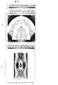
- An example of fluid simulation to a capture structure An example of fluid simulation to a capture structure.
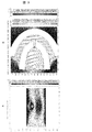
- An example of fluid simulation to a capture structure An example of fluid simulation to a capture structure.
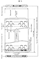
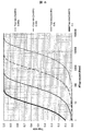
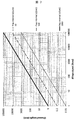
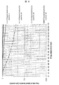
- Schematic regarding parameters for capturing all biological materials Capture rate and number of capture structures. (Liquid feeding direction) Number of capture structures (liquid feeding direction) and channel length. Probability that at least two or more bio-related substances are captured by the same capturing structure. Probability that two biological materials will be captured by the same capture structure. Probability that three biological materials will be captured by the same capture structure.
- Schematic which shows an example of a capture structure Schematic which shows an example of an analyzer.
- Schematic which shows an example of an analyzer Schematic which shows an example of a flow cell.
- the flowchart which shows the example of the control procedure at the time of washing
- the flowchart which shows the example of the control procedure at the time of a flow cell internal washing
- the flowchart which shows the example of the procedure which attracts
- the flowchart which shows the example of the procedure of the reagent injection
- the schematic diagram which shows the relationship of the pressure change in a flow cell, and the timing of the insertion / separation to the injection port of a sampling nozzle, and the drive of the plunger of a micro syringe.
- the flowchart which shows the example of the procedure of a detection.
- the present invention can be applied to general analyzers that perform analysis by arranging a plurality of biological substances at single and independent positions.
- an example where the present invention is applied to bacterial analysis will be described.
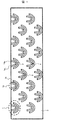
- FIG. 1 is a schematic diagram illustrating an example of a capture structure according to the present invention.
- the capture structure 1 is a structure in which a structure 1a having a slit and a structure 1b having no slit are a pair, and a plurality of the structures are arranged.
- the structure 1a having a slit is composed of a left side 1a L of the structure having a slit and a right side 1a R of the structure having a slit, and a slit 2 exists between them.
- a solution containing a bio-related substance 4 (not shown) is injected from an inlet (see FIG. 14) on the upper side of FIG. 1 and fed through the flow path 3 and discharged at the lower side of FIG. 1 (see FIG. 14). ).
- the height of the capture structure 1 is assumed to be equal to the height of the flow path.
- the solution containing the biological substance 4 flows into the structure 1a having the slit with a certain probability, passes through the slit 2, and the structure 1a having the slit and the structure not having the slit. It flows out of the two gaps 1b.
- the biological material 4 is captured in the dead water area 5 with a certain probability.
- the dead water area 5 is an area that is not related to flow rate communication in a spiral place even if there is no flow or a flow.
- the biological material 4 that has passed through the slit 2 is trapped in the dead water region 5 with a certain probability by diffusion, inertial force, or its mobility.
- the dead water area 5 is formed in a region such as a sudden expansion portion, a sudden reduction portion, or a curved portion. It is also possible to widen the area of the dead water area 5 by optimizing the structure such as making a dent in a place near the dead water area of the structure 1b that does not have a slit.
- the biological material 4 trapped in the dead water area 5 receives almost no fluid force. Therefore, no stress is generated in the biological material 4 and it does not dissolve.
- the structure 1b which does not have a slit exists in the downstream of the dead water area 5. FIG. Therefore, even if the biological substance 4 is small, it does not flow downstream from the dead water area 5.
- the structure 1a having the slit has an action of filling the solution containing the biological substance 4 from the downstream side of the flow path of the structure 1b having no slit through the slit 2 to the upstream side of the flow path, bubbles are easily removed.
- the structure 1a having a slit and the structure 1b not having a slit are configured by a part of an elliptical arc, but may be configured by a part of an arc or a part of a triangle. Due to the difference in structure shape, a difference in flow occurs, resulting in a difference in the capture rate of the biological substance 4.
- FIG. 2A shows a fluid simulation result when the capture structure is placed in the center of a 1 mm wide channel and fed from the left side to the right side at a flow rate of 1 mm / s.
- the width of the slit is 5 ⁇ m.
- FIG. 2B is an enlarged view of the region of the capturing structure, and the direction in which the solution flows is indicated by an arrow.
- the solution that has passed through the slit branches and flows out toward the two gaps between the structure 1a having the slit and the structure 1b having no slit. Therefore, the dead water area is formed in the branching area.
- FIG. 3A shows a fluid simulation result when the capture structure is placed at a position shifted from the center of the channel having a width of 1 mm and fed from the left side to the right side at a flow rate of 1 mm / s.
- the width of the slit is 5 ⁇ m.
- FIG. 3B is an enlarged view of the region of the capturing structure, and the direction in which the solution flows is indicated by an arrow.
- the solution that has passed through the slit flows out toward one of the two gaps between the structure 1a having the slit and the structure 1b having no slit. Further, a flow from one gap to the other gap is formed. Therefore, unlike FIG. 2, since there is no branching area, the dead water area is not formed.
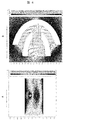
- FIG. 4A shows a fluid simulation result when the capture structure is placed at a position shifted from the center of the 1 mm wide channel and fed from the left side to the right side at a flow rate of 1 mm / s.
- the conditions are the same as in FIG. 3 except that the width of the slit is 30 ⁇ m.
- FIG. 4B is an enlarged view of the region of the capturing structure, and the direction in which the solution flows is indicated by an arrow.
- the solution that has passed through the slit branches and flows out toward the two gaps between the structure 1a having the slit and the structure 1b having no slit. Therefore, unlike the case of FIG. 3, the dead water area is formed in the branching area. Therefore, the structure having the slit has an advantage that a dead water area can be formed by adjusting parameters such as the width of the slit.
- the capture rate of the biological substance to the capture structure is [ ⁇ : (flow rate flowing into the capture structure) / (total flow rate)] ⁇ [ ⁇ : the capture structure.
- ⁇ may be multiplied by a safety factor.
- the capture rate (/ 1 capture structure) can be calculated by [(width of the slit) ⁇ (average flow velocity in the slit)] / [(width of the flow channel) / (average flow velocity of the flow channel)]. .
- the capture rate (/ 1 capture structure) is calculated as 0.000002 at [(0.005 mm) / (0.0004 mm / s)] / [(1 mm) / (1 mm / s)]. Is done. This is the probability that two of the one million biological substances can be captured by the capturing structure.
- FIG. 4 in which only the slit width is changed from 5 ⁇ m in FIG.
- the capture rate (/ 1 capture structure) is [(0.03 mm) / (0.0001 mm / s)] / [( 1mm) / (1mm / s)] is 0.00005, which is approximately 25 times larger. Therefore, the structure having the slit adjusts the capture rate (/ 1 capture structure) by adjusting parameters such as the interval between the capture structures, the width of the slit, the width of the flow path, and the flow velocity. There are advantages you can do. For example, the capture rate (/ 1 capture structure) increases to 0.001 simply by changing the width 1 mm of the flow path in FIG. 4 to 0.36 mm. However, as shown in FIGS.
- the flow direction of the solution containing the biological substance changes immediately before it flows into the capture structure, but since the inertial force acts on the biological substance, the solution suddenly The direction cannot be changed, and it tends to flow into the capture structure. Therefore, the actual capture rate (/ 1 capture structure) is higher than the calculation result of the flow rate ratio. Therefore, the higher the flow velocity, the stronger the inertial force works, and the higher the actual capture rate (/ 1 capture structure).
- FIG. 5 shows parameters for calculating conditions for capturing all bacteria. If the capture rate of one capture structure is known, the conditions for capturing all the biological substances can be calculated. #Bacteria is the number of bacteria before feeding to the capture structure, and # Non-trapped Bacteria is the number of bacteria after feeding to the capture structure. The liquid feeding direction is the direction indicated by the arrow of Flow direction. Trap rate is the rate at which bacteria are trapped in the trapping structure and is calculated as [(#Bacteria)-(# Non-trapped Bacteria)] / (# Bacteria).
- the capture structure is shown in a simplified manner by a semicircular arc, and the interval between adjacent capture structures is defined as TrapTinterval (x) and Trap interval (y).
- the x direction is a direction parallel to the liquid feeding direction
- the y direction is a direction perpendicular thereto.
- #Trap Object (Column) is the number of captured structures arranged in the y direction
- #Trap Object (Row) is the number of captured structures arranged in the x direction.
- Channel length is the length of the channel in which the capturing structure in the liquid feeding direction (x direction) is formed, and is calculated as Trap interval (x) ⁇ # Trap Object (Row).
- Channel width is the length of the channel in which the capture structure in the y direction is formed, and is calculated as Trap interval (y) ⁇ # Trap Object (Column).
- Trap rate (/ width) indicates the trapping rate when passing through one row of the trapping structures arranged in the y direction.
- #Trapped bacteria (1st column) is the number of bacteria trapped in the capture structure of the first column, and is calculated by [Trap rate (/ width)] ⁇ (#Bacteria). #Trapped bacteria (1st column) becomes smaller as the number of captured structures passing through increases.
- Trap rate (/ width) is equal to the trap rate (/ 1 trapping structure) when the width of the flow path is TrapTinterval (y) in FIGS. This is because the capture rate of the trap structure per Trap interval (y) is the same as the trap rate when a plurality of trap structures are arranged in parallel.
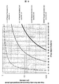
- Fig. 6 shows the relationship between Trap rate and #Trap object (Row) when Trap rate (/ width) is swung from 0.0001 to 0.1.
- Trap rate (/ width) is 0.01
- the trapping structure of 300 rows for 95% trapping, 470 rows for 99% trapping, and 700 rows for 99.9% trapping is used in the direction of liquid feed ( It is necessary to arrange in the x direction.
- TrapTrate (/ width) is 0.001, 3000 rows to capture 95%, 4700 rows to capture 99%, and 7000 rows to capture 99.9% It is necessary to arrange in the (x direction).
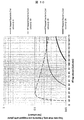
- Fig. 7 shows the relationship between #Trap object (Row) and Channel length (mm) when Trap interval (x) is swung from 10 to 1000 ⁇ m.
- Trap interval (x) is 100 ⁇ m
- 700 capture structure that traps 99.9% with Trap rate (/ width) is 0.01, 70mm
- Trap rate (/ width) is 0.
- a Channel length of 700 mm is required.
- a typical microchip is easy to handle for users and the upper limit is about a postcard size (100 mm x 150 mm), in order to realize a 700 mm channel length, it is realized with a meandering channel. There is a need to.
- the minimum trapping structure size for trapping bacteria is obtained, and the minimum Trap interval (x) is obtained.
- the maximum value of Channel length including a meandering flow path can be obtained and divided by the minimum Trap interval (x).
- #Trapped bacteria (1st column) is 1 or less, all bacteria can be placed in a single and independent position. Since #Trapped bacteria (1st column) is [Trap rate (/ width)] ⁇ (#Bacteria), Trap rate (/ width) may be set to 1 / # Bacteria or less. For example, if the number of #Bacteria is 1000, all bacteria can be arranged in a single and independent position by setting Trap rate (/ width) to 0.001 or less. If #Bacteria is not known, #Trapped bacteria (1st column) may be larger than 1, so that a plurality of bacteria may be captured by the same capturing structure.
- #Trapped bacteria (1st column) is reduced by dividing the solution containing # Bacteria, or Trap rate (/ width) is designed to be sufficiently small, so that #Trapped bacteria (1st There is a possibility that column) can be 1 or less.
- the table below shows the probability of each captured state when #Trapped bacteria (1st column) is 10 and #Trap object (Column) is 100.
- the semicircle in the capture example column indicates the capture structure, and the black circle ( ⁇ ) indicates the captured bacteria.
- Fig. 8 shows the relationship between #Trap object (Column) when #Trapped bacteria (1st column) is shaken from 1 to 28 and the probability that at least two bacteria are captured by the same capture structure. From this, when #Trapped bacteria (1st column) is 10 and #Trap object (Column) is 100, at least two or more bacteria are captured by the same capture structure with a probability of 0.37 (37%).
- #Trapped bacteria (1st column) is 10
- #Trap object (Column) is 100
- Fig. 9 shows the relationship between #Trap object (Column) when #Trapped bacteria (1st column) is shaken from 1 to 28 and the probability that only two bacteria are captured by the same capture structure.
- #Trappedactbacteria (1st column) is 10
- #Trap object (Column) is 100
- only two bacteria are captured by the same capturing structure with a probability of 0.75 (75%).
- the probability of multiple capture is 0.37
- the concentration of the solution containing bacteria must be adjusted.
- a structure for capturing bacteria is provided in the flow path of the microchip, and captured while flowing a solution containing bacteria. Since a necessary amount of a solution containing bacteria can be fed, it is not necessary to adjust the concentration of the solution containing bacteria, and even a very dilute solution can be used.
- bacteria are captured by the slits, external force is applied and stress is generated. Bacteria are not captured by slits, but are captured in dead water areas, so no external force is applied.
- a plurality of bacteria are captured by one capturing structure.
- #Trapped bacteria (1st column) it is possible to prevent multiple bacteria from being captured by one capture structure.
- Bacteria may be lysed when pumped at high speed. No external force from the fluid is applied to trap the bacteria in the dead water area.
- this invention has the following three advantages by setting it as the structure which is a pair of the structure which has a slit, and the structure which does not have a slit.
- the structure having the slit can fill the solution from the downstream side of the flow path to the upstream side of the flow path of the structure having no slit through the slit, the bubbles are easily removed.
- a structure having a slit can form a dead water area by adjusting parameters such as the width of the slit.
- the structure having slits can change the capture rate by adjusting parameters such as the interval between the capture structures, the width of the slits, and the flow velocity. By increasing the capture rate, all biological substances can be captured.
- the slit 2 shown in FIG. 1 is one place, a plurality of slits may be provided as in Non-Patent Document 2.
- the capture rate of the biological substance to the capture structure is [ ⁇ : (flow rate flowing into the capture structure) / (total flow rate)] ⁇ [ ⁇ : bio-related substance in the capture structure It was calculated by [Capture rate] and explained that it can be approximated by ⁇ . It has been explained that ⁇ can be increased to 0.001 by changing the width of the slit and the width of the flow path because the larger ⁇ is, the smaller the number of necessary capturing structures.
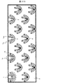
- FIG. 11 is a schematic diagram showing an example of an arrangement for setting ⁇ to 1. Since the solution containing all the biological substances 4 passes through the slits of the capturing structure, it can be regarded as a shape in which the interval between the capturing structures in FIG. A solution containing a biological substance 4 (not shown) is injected from an inlet (not shown) on the upper side of FIG. 11, is fed through the flow path 3, and is discharged from an outlet (not shown) on the lower side of FIG. 11. In this process, the solution containing the biological material 4 (not shown) passes through the slit 2a and flows out from the slit 2b or 2b ′. At this time, the biological material 4 is captured in the dead water area 5 with a certain probability.
- the dead water area 5 is an area that is not related to flow rate communication in a spiral place even if there is no flow or a flow.
- the biological material 4 that has passed through the slit 2 is trapped in the dead water region 5 with a certain probability by diffusion, inertial force, or its mobility. Therefore, unlike a filter, it is not captured by a slit (hole) having a size smaller than that of the biological substance 4. It is also possible to collect the biological material 4 captured in the dead water area. This is because the biological substance 4 captured in the dead water area deviates from the area of the dead water area 5 due to its own diffusion and mobility when the liquid feeding is stopped. Next, the solution is fed in the opposite direction.
- the recovery liquid is injected from an inlet (not shown) on the lower side of FIG. 11, passes through the slit 2b or 2b ′ through the flow path 3, and flows out of the slit 2a.
- the recovered liquid is discharged together with the biological substance 4 from the outlet. Since FIG. 11 has a vertically symmetric shape, when the recovery liquid is injected from an inlet (not shown) on the lower side of FIG. 11, the dead water area 5 that originally existed disappears, and instead the slits 2b and 2b ′ are located on the upper side of the figure. A dead water area is formed. Therefore, even when liquid is fed in the reverse direction, there is a possibility of being caught before reaching a discharge port (not shown).
- the biological material can be recovered from the discharge port by repeating only the liquid feeding and the liquid feeding stop without changing the liquid feeding direction. If the biological substance 4 can be recovered, the nucleic acid can be extracted and analyzed such as gene analysis such as PCR.
- FIG. 12 is a schematic view showing an example of an analysis apparatus (bacteria analysis apparatus) according to the present invention
- FIG. 12 (a) is a schematic plan view
- FIG. 12 (b) is a schematic front view thereof.
- An explanation will be given by setting the XYZ axes as shown in the figure.
- the analyzer includes a reagent rack table 13 on which a reagent rack 12 that holds a plurality of reagent containers 11 is placed, a flow cell stage 31 that can move while holding one or a plurality of flow cells 30, and a liquid from the tip.
- Nozzle 20 capable of sucking / discharging the sample, nozzle drive mechanism for driving the sampling nozzle 20 to a desired three-dimensional position, a cleaning tank 68 for cleaning the sampling nozzle 20, and a biological body captured in the flow cell 30 by reagent injection
- a detection unit 40 is provided for analyzing the reaction with the substance and the biological substance itself.
- the reagent suction / discharge, cleaning, and the like by the sampling nozzle 20 are executed by a liquid feeding system (not shown). The liquid feeding system will be described in detail with reference to FIG.
- Each part of the analysis device is under the control of the control / calculation unit 50, and the control / calculation unit 50 controls the analysis device according to a program set in the control / calculation unit 50 via the input unit 51 and continuously operates.
- the memory of the control / arithmetic unit 50 includes analysis procedures, coordinate positions of a plurality of reagent containers 11 and cleaning tanks 68 arranged in the reagent rack 12, types of reagents contained in each reagent container, and reagent in the flow cell 30. And information such as the coordinate position of the injection port for injecting the cleaning liquid and the processing procedure of the detection result by the detection unit 40 are stored.
- the control / arithmetic unit 50 controls each part of the apparatus according to the analysis program while referring to the information stored in the memory, and executes the analysis.
- the sampling nozzle 20 is a hollow nozzle made of a metal material, for example, SUS, having an outer diameter of 1 mm, an inner diameter of 0.5 mm, and a length of about 150 mm.
- a desired amount of reagent can be aspirated from a desired reagent container 11 placed in the reagent rack 12 and discharged to the flow cell 30 or the like.
- the sampling nozzle 20 has a material and a structure suitable for liquid level detection.
- the liquid level detection is performed by the control / calculation unit 50 using a known method for detecting the liquid level from a change in capacitance when the tip of the metal sampling nozzle 20 comes into contact with a conductive region such as the liquid level. It is executed by the provided liquid level detection unit 53.
- the liquid level detection signal output from the liquid level detection unit 53 is used for subsequent device control.
- the nozzle drive mechanism includes a guide rail 21, a linear movement unit 22 that linearly moves in the X-axis direction along the guide rail 21, and an arm 24 that can be rotated around a rotation shaft 23 provided in the linear movement unit 22.
- a sampling nozzle 20 is fixed to a portion of the arm 24 opposite to the rotating shaft 23.
- the linear movement unit 22 has, for example, a pinion that meshes with a rack provided on the guide rail 21 and can move to a desired position in the X-axis direction by rotationally driving the pinion by a stepping motor.
- the rotary shaft 23 can be rotated in the XY plane by a stepping motor and moved up and down in the Z-axis direction to position the tip of the sampling nozzle 20 at a desired Z-axis direction position.
- the sampling nozzle 20 combines the linear movement in the X-axis direction by the nozzle drive mechanism, the rotational movement around the rotation axis 23, and the vertical movement in the Z-axis direction, thereby combining the reagent container 11 at an arbitrary position arranged in the reagent rack 12.
- the washing tank 68, and an access port of the flow cell described later can be accessed.
- the detection unit 40 includes a light source 41 that irradiates the flow cell, and a diffraction grating, a mirror, a filter, a slit, and a confocal detection that disperses Raman light generated from a biological substance present in the flow cell 30 by light irradiation from the light source. It is detected by an imaging device 42 such as a CCD through an optical component such as a hole.
- the detection unit 40 is capable of bright field, dark field, phase difference, differential interference, fluorescence, light emission, and the like by selecting an optical system, and is not limited to Raman observation.
- the flow cell 30 can be moved in the XY axis directions by the flow cell stage 31.
- the flow cell 30 When the flow cell 30 is subjected to operations such as reagent injection and washing via the sampling nozzle 20, it is located at a position off the lower side of the detection unit 40 as shown in the figure, and when performing detection using the detection unit 40. Is moved to a position below the detection unit 40 by the flow cell stage 31.
- Input information input from the input unit 51, information on an analysis process such as a captured image by the detection unit 40, information on the current apparatus state and apparatus parameters, information on completed processes in all analysis processes, analysis results, etc. Is displayed on the display unit 52.
- the detection unit 40 can detect the reagent while discharging the reagent from the sampling nozzle 20 from the upper side of the flow cell 30.
- the flow cell 30 is not limited to the horizontal arrangement of FIG.
- the flow cell 30 can be arranged vertically, and detection can be performed by the detection unit 40 arranged vertically while feeding liquid.
- the specific gravity of the bacteria is lighter than that of the reagent, buoyancy can be captured, and when the specific gravity is heavy, it can be captured using gravity.
- FIG. 13 is a schematic view showing an example of a liquid feeding system incorporated in the analyzer of this embodiment.
- the reagent suction / discharge from the tip of the sampling nozzle 20 and the cleaning of the sampling nozzle 20 are performed by this liquid feeding system.
- the liquid feeding system of the present embodiment includes a microsyringe 60 for weighing and aspirating and discharging a reagent from the tip of the sampling nozzle 20, a first flow path 62 for supplying the cleaning liquid to the sampling nozzle 20 and the cleaning tank 68, and A second flow path 63 is provided.
- the cleaning liquid stored in the cleaning liquid tank 64 is sucked up by the pump 65 that is continuously operated, and returned to the cleaning liquid tank 64 again through the cleaning liquid circulation channel 66.
- the cleaning liquid is constantly circulated in the direction of the arrow through the cleaning liquid circulation channel 66 by the pump 65.
- the first channel 62 one end of which is connected to the cleaning liquid circulation channel 66 via the first electromagnetic valve 71, communicates with the inside of the sampling nozzle 20 via the microsyringe 60.
- the second flow path 63 whose one end is connected to the cleaning liquid circulation flow path 66 via the second electromagnetic valve 72 has the other end opened to the side wall of the cleaning tank 68.
- pure water is used as the cleaning liquid.
- the tip of the sampling nozzle 20 When the tip of the sampling nozzle 20 is moved into the cleaning tank 68 by the nozzle driving mechanism, and only the first electromagnetic valve 71 is opened in this state, the cleaning liquid pumped from the pump 65 passes through the sampling nozzle 20 and the cleaning tank 68. The inside of the sampling nozzle 20 can be cleaned thereby. During cleaning, the plunger 61 of the microsyringe 60 may or may not be moved. Further, when only the second electromagnetic valve 72 is opened, the cleaning liquid is ejected from the inner wall of the cleaning tank 68, whereby the outside of the sampling nozzle 20 can be cleaned. Furthermore, when the first electromagnetic valve 71 and the second electromagnetic valve 72 are simultaneously opened, the inside and the outside of the sampling nozzle 20 can be simultaneously cleaned in the cleaning tank 68. The opening / closing control of the first electromagnetic valve 71 and the second electromagnetic valve 72 is performed by the control / calculation unit 50.
- the ratio of the cleaning liquid supplied to the sampling nozzle 20 via the first flow path 62 and the cleaning liquid supplied to the cleaning tank 68 via the second flow path 63 is provided at a location near the cleaning tank 68 of the second flow path 63.
- the flow rate adjusting throttle 67 is set.
- the cleaning liquid that has cleaned the sampling nozzle 20 is stored in the waste liquid tank 69.
- the cleaning liquid stored in the cleaning tank 68 can be stored in the waste liquid tank 69 using a waste liquid discharge pump (not shown).
- the cleaning liquid can also be sent from the cleaning liquid tank 64 by sealing the cleaning tank 68, opening the second electromagnetic valve 72, and pulling it with the waste liquid discharge pump.
- the liquid in the first flow path 62, the second flow path 63, and the cleaning liquid circulation path 66 can be removed by emptying the cleaning liquid tank 64 and performing the same operation, and further opening the first electromagnetic valve 71.
- the cleaning liquid does not come out from the cleaning tank 68, so that the sampling nozzle 20 cannot be cleaned. In this case, since the nozzle level detection function does not work, a failure can be detected. Further, the cleaning liquid in the cleaning liquid tank 64 is consumed by performing the cleaning operation.
- the cleaning liquid tank 64 is provided with a liquid level sensor, and when the cleaning liquid in the cleaning liquid tank 64 becomes low, the cleaning liquid tank 64 is replenished with the cleaning liquid from a separately installed cleaning liquid replenishment tank (not shown).
- a large amount of cleaning liquid can be supplied to the inside and outside of the sampling nozzle or both inside and outside by a pump in a short time, and adheres to the sampling nozzle after use. Can be sufficiently washed in a short time. Therefore, it is possible to avoid the contamination of the reagent and improve the analysis accuracy.
- the cleaning time can be shortened to improve the analysis throughput.
- the reagent rack 12 is provided with a temperature control unit such as a temperature sensor and a Peltier element, and the reagent held in the reagent container 11 is maintained at a constant temperature.
- a temperature control unit such as a temperature sensor and a Peltier element
- the reagent held in the reagent container 11 is maintained at a constant temperature.
- the reagent group held in the first region 12a of the reagent rack is maintained at room temperature
- the reagent group held in the second region 12b is maintained at 4 ° C.
- the temperature control of the reagent rack 12 can also be performed from the control / calculation unit 50.
- the reagent rack 12 is provided with a premixing container 14 for use in preparing the mixed reagent.
- the respective reagents sucked by the sampling nozzle 20 from the separate reagent containers 11 are once discharged into the premixing container 14, and the mixed reagent prepared by mixing in the premixing container 14 is again used.
- the sample is sucked by the sampling nozzle 20 and supplied to the flow cell 30.
- FIG. 14 is a schematic diagram illustrating an example of a flow cell.
- 14A is a perspective view of the flow cell
- FIG. 14B is a cross-sectional view taken along the line XX ′ of FIG. 14A.
- the flow cell of this example includes an injection port 32, a discharge port 33, and a flow path 34 through which a liquid flows.
- a flow path 34 is formed between the upper substrate 36 and the lower substrate 37, and the flow cell 30 is designed so that the capturing structure 1 shown in FIG.
- the flow path 34 functions as a flow path to which a reagent for bacterial analysis and a cleaning liquid are supplied, and also functions as a reaction chamber in which a reaction occurs.
- a spacer 38 is disposed between the upper substrate 36 and the lower substrate 37 in order to secure a space for the flow path 34.
- the spacer 38 is integrated with the upper substrate 36 or the lower substrate 37, so that the flow cell 30 having the capturing structure of FIG. 1 or FIG. 11 can be manufactured.
- the reagent is injected from the injection port 32 and discharged from the discharge port 33.
- the thickness of the spacer can be 50 to 100 ⁇ m
- the width of the flow path can be 1 to 30 mm
- the length of the flow path can be 75 to 100 mm, but is not limited to these values.
- the upper substrate 36 on the side facing the detection unit 40 is made of glass, quartz, sapphire, PDMS, or resin such as acrylic resin or cycloolefin polymer that can transmit excitation light and fluorescence.
- FIG. 14 shows an example of the flow cell 30 in which three flow paths are formed, but the number of flow paths is not limited to three. When the number of channels is large, a large number of reactions can be performed at one time, and high-throughput analysis is possible.
- the flow cell 30 is controlled to a predetermined temperature by a temperature control unit provided in the flow cell stage 31.
- the control / calculation unit 50 first controls the nozzle driving mechanism to move the sampling nozzle 20 to the cleaning tank 68 (S11).
- the controller / arithmetic unit 50 controls the first electromagnetic valve 71 connected to the cleaning liquid circulation channel 66 in which the cleaning liquid is circulated by the pump 65 to open (S12).
- the plunger 61 of the microsyringe 60 may or may not be moved as long as it is being cleaned.
- the cleaning liquid pumped from the pump 65 enters the microsyringe 60 through the first electromagnetic valve 71 and the first flow path 62, and is directly jetted from the nozzle tip into the cleaning tank 68 through the sampling nozzle 20.
- the In this state the inside of the nozzle is cleaned. Pure water was used as the cleaning liquid.
- the control / calculation unit 50 controls the second electromagnetic valve 72 connected to the cleaning liquid circulation channel 66 to open (S13). Then, the cleaning liquid pumped from the pump 65 is ejected from the inner wall of the cleaning tank 68 through the second electromagnetic valve 72 and the second flow path 63 into the cleaning tank 68, and the sampling nozzle 20 located in the cleaning tank 68. The outside is cleaned. In this way, as shown in FIG. 5, the inside and outside of the sampling nozzle 20 are cleaned. When the cleaning is completed, the control / calculation unit 50 closes the first electromagnetic valve 71 and the second electromagnetic valve 72 (S14).
- the first electromagnetic valve 71 and the second electromagnetic valve 72 may be opened simultaneously. In this case, the inside and outside of the sampling nozzle are cleaned simultaneously. The order of cleaning may be first outside the nozzle and then inside the nozzle.
- the microsyringe 60 and the sampling nozzle 20 are connected from the first flow path 62 connected to the cleaning liquid circulation flow path 66.
- the tip is filled with the cleaning liquid.
- the cleaning method of the present embodiment can supply a large amount of cleaning liquid to the inside and outside of the sampling nozzle or both inside and outside in a short time, thereby shortening the cleaning time and improving the analysis throughput. .
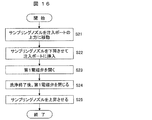
- the control / calculation unit 50 controls the nozzle drive mechanism to move the sampling nozzle 20 to a position above the injection port 32 of the flow cell 30 (S21). Next, the sampling nozzle is lowered and the tip of the nozzle is inserted into the injection port (S22). Next, the control / calculation unit opens the first electromagnetic valve 71 (S23). At this time, the plunger 61 of the microsyringe 60 may be fixed or moved. Then, the cleaning liquid pumped from the pump 65 enters the microsyringe 60 through the first electromagnetic valve 71 and the first flow path 62, and further flows from the tip of the sampling nozzle 20 through the injection port 32 to the flow path 34 of the flow cell 30. The flow cell is washed.
- the cleaning liquid that has cleaned the flow path of the flow cell is stored in the waste liquid tank 69.
- the control / calculation unit 50 closes the first electromagnetic valve 71 (S24).
- the controller / arithmetic unit 50 controls the nozzle driving mechanism to raise the sampling nozzle 20 and separate it from the injection port 32 (S25).
- the control / arithmetic unit 50 does not immediately close the first electromagnetic valve 71 and instructs the nozzle drive mechanism to raise the sampling nozzle, but is determined in advance as the time until the pressure of the cleaning liquid in the flow cell is stabilized. Command the sampling nozzle to rise. This will be described in more detail in the section of reagent injection into the flow cell.
- Reagent Aspiration from Reagent Container A procedure for aspirating a reagent from the reagent container 11 at a predetermined position in the reagent rack 12 by the sampling nozzle 20 will be described with reference to the flowchart of FIG.
- the reagent will be described as a solution containing bacteria.
- the control / calculation unit 50 determines the type of reagent to be aspirated and the amount to be aspirated according to a preprogrammed procedure, and then determines the correspondence between the position of the reagent container stored in the memory and the type of reagent. The moving position of the sampling nozzle is determined with reference to the information. Next, the control / calculation unit 50 controls the nozzle driving mechanism to move the sampling nozzle 20 to a position above the reagent container containing the target reagent (S31). Subsequently, the sampling nozzle is lowered and the tip of the nozzle is inserted into the reagent container (S32). At this time, the liquid level detection function of the liquid level detection unit 53 is used to detect the reagent liquid level in the reagent container.
- the sampling nozzle When the reagent liquid level is detected, the sampling nozzle is further lowered by a certain distance, and the sampling nozzle is stopped with the nozzle tip inserted into the reagent solution by a predetermined depth (S33).
- the control / calculation unit 50 drives the plunger 61 of the microsyringe 60 by a predetermined amount to the suction side, and sucks and holds a predetermined amount of reagent at the tip of the cleaning liquid filled in the sampling nozzle 20. (S34).
- control / arithmetic unit 50 controls the nozzle driving mechanism to drive the sampling nozzle upward to remove the tip of the nozzle from the reagent container, and further move the sampling nozzle to the cleaning tank 68 (S35). Thereafter, the control / calculation unit 50 opens the second electromagnetic valve 72. Then, the cleaning liquid is ejected from the inner wall surface of the cleaning tank 68, and the reagent adhering to the outside of the sampling nozzle 20 is washed away (S36). The reagent sucked into the sampling nozzle is held in the nozzle as it is without being washed. When the outside of the sampling nozzle is cleaned, the control / calculation unit 50 closes the second electromagnetic valve 72 and controls the nozzle driving mechanism to move the sampling nozzle 20 upward.
- the tip of the sampling nozzle 20 is inserted into the reagent to the minimum depth by utilizing the liquid level detection function, the amount of the reagent that adheres to the outside of the sampling nozzle 20 and is washed away in the washing tank 68 is always determined. It can be suppressed to the minimum. Further, as another advantage of detecting the liquid level of the reagent, the remaining amount of the reagent can be known from information on the shape of the reagent container and the liquid level. This makes it possible to calculate the number of remaining bases that can be analyzed and to inform the user of the time for reagent replacement.
- the control / calculation unit 50 controls the nozzle drive mechanism to move the sampling nozzle 20 to a position above the injection port 32 of the flow cell 30.
- the sampling nozzle 20 is lowered and the tip of the nozzle is inserted into the injection port 32 (S41).
- the control / calculation unit 50 drives the plunger 61 of the microsyringe 60 in the discharge direction, and injects the reagent sucked into the tip of the cleaning liquid filled in the sampling nozzle 20 into the flow cell 30 through the injection port 32 ( S42).
- a large number of capture structures 1 shown in FIG. 1 are arranged in the flow cell 30, and bacteria contained in the reagent are captured and captured by the capture structure.
- the control / calculation unit 50 waits until the pressure in the flow cell 30 is stabilized (S43), and controls the nozzle driving mechanism to raise the sampling nozzle upward (S44).
- FIG. 19 is a schematic diagram showing the relationship between the pressure change in the flow cell and the timing of inserting / removing the sampling nozzle into / from the injection port and driving the plunger of the microsyringe.
- the horizontal axis is time.
- FIG. 19 shows that the sampling nozzle 20 is inserted into the injection port 32 of the flow cell at time t0 and is pulled upward from the injection port 32 at time t4.
- the plunger 61 of the microsyringe 60 is driven to discharge the reagent from time t1 to time t2.
- the reagent is pressure-injected into the flow cell of the flow cell having a small conductance by driving the plunger 61 of the microsyringe 60. Therefore, immediately after the driving of the plunger 61 is stopped (time t2), the pressure in the flow cell 30 is high, and if the sampling nozzle 20 is immediately pulled away from the injection port 32, the reagent may flow backward and overflow from the injection port 32.
- time t2 end time t2 until the pressure in the flow cell 30 stabilizes, the sampling nozzle 20 is separated from the injection port 32 and pulled upward. That is, the time t4 when the sampling nozzle 20 is pulled up from the injection port 32 is set to t4> t3.
- the waiting time until the pressure in the flow cell stabilizes (t3-t2) is determined depending on the viscosity of the reagent to be injected, the injection speed, the flow path resistance of the flow cell, and the like, but typically 0.5 seconds to 1 Just wait about a second.
- control / calculation unit 50 controls the nozzle drive mechanism to move the sampling nozzle 20 to the cleaning tank 68. Then, the inside and outside of the sampling nozzle are cleaned by the procedure shown in “(1) Sampling nozzle cleaning” to prepare for the next operation.
- the amount of reagent to be injected from the sampling probe into the flow cell is the volume of the dead space generated at the injection port 32 of the flow cell. An extra amount is sufficient.
- the volume of dead space is estimated to be 5 ⁇ L or less. Therefore, the amount of the reagent to be injected into the flow cell 30, that is, the amount of the reagent to be sucked into the sampling nozzle 20 from the reagent container 11 is required to be at least the volume of the flow cell, but at most about 5 ⁇ L to 10 ⁇ L for the volume of the flow cell The amount added is sufficient.
- the amount of reagent sucked from the reagent container for injection into the flow cell is small, and the amount of reagent that adheres to the outside of the sampling nozzle 20 and is washed away is small. That is, the amount of the reagent used is small and the reagent is not wasted.
- the reagent aspiration and the liquid feeding to the flow cell are realized by the sampling nozzle, and the liquid feeding time can be shortened as compared with the method using the tube and the switching valve. Also, there is very little reagent carryover, and a purer reagent can be supplied to the flow cell.
- the temperature of the flow cell 30 is controlled to the optimum temperature (S51).
- the control / calculation unit 50 performs “(3) Reagent aspiration from the reagent container” with respect to the processing described in the above “(2) Flow cell cleaning” or the cleaning liquid (reagent) placed on the reagent rack 12.
- (4) Reagent injection into the flow cell ” can be executed to clean the inside of the cell (S52).
- the control / arithmetic unit 50 controls the flow cell stage 31 to move the flow cell 30 to a position below the detection unit 40 (S53).
- a phase contrast microscope When confirming transparent biological materials such as cells and bacteria, a phase contrast microscope is generally used. When the bacteria are observed with a phase contrast microscope, relatively strong light called halo is generated around the bacteria. The size of bacteria is as small as a few microns, but the size of the halo is so large that it is out of focus of the microscope and can be tens of microns. Therefore, by finding the halo in order to find the capture structure in which the bacteria are captured, the bacteria are present at the center of the halo, and further, the deviation from the focus of the microscope can be corrected by the size of the halo.
- the control / calculation unit 50 emits light from the detection unit 40 and detects Raman light emitted from the bacteria in the flow cell 30 (S54).
- Gram determination reagent and drug sensitivity determination can be performed by feeding a Gram determination reagent or a reagent for drug sensitivity test to bacteria trapped in the flow cell.
- Bacteria collection is performed at the stage when the detection of (5) in the flow cell is completed.
- the controller / arithmetic unit 50 controls the nozzle driving mechanism to insert the sampling nozzle 20 into the injection port 32 of the flow cell 30 in which the reaction has ended (S91).
- the plunger 61 of the microsyringe 60 is driven to the suction side to suck bacteria in the flow cell 30 (S92).
- the plunger 61 of the microsyringe 60 may be sucked at the same liquid feeding speed while feeding liquid in the direction of the sampling nozzle 20 using a pump (not shown) on the discharge side of the flow cell.
- control / arithmetic unit 50 controls the nozzle driving mechanism to move the sampling nozzle 20 to the container for the collected reagent prepared in the reagent rack 12 (S93), and discharges the bacteria sucked into the container. And collected (S94).
- a container for recovered bacteria is prepared for each sample separately.
- the biological material can be recovered from the discharge port by repeating only the liquid feeding and the liquid feeding stop without changing the liquid feeding direction.
- the control / calculation unit 50 controls the nozzle drive mechanism to move the sampling nozzle 20 to the cleaning tank 68, cleans the inside and outside of the sampling nozzle 20, and prepares for the next operation.
- the reagent recovered in the recovery reagent container can be used in the same manner as a reagent in a normal reagent container.
- the collected bacteria can be used for analysis such as extraction of nucleic acids and identification of bacteria by a nucleic acid amplification method such as PCR.
- the liquid feeding system of the above embodiment has a cleaning liquid circulation channel 66 including a pump 65, and the cleaning liquid is transferred from the cleaning liquid circulation channel 66 to the first channel 62 or the second channel 63 via the electromagnetic valves 71 and 72.
- the cleaning liquid circulation channel is not necessarily essential.
- the Example which applied this invention to the bacteria analysis was demonstrated.
- the application of the present invention is not limited to bacterial analysis, but a solution containing biologically relevant substances such as cells or bacteria is sent to the device and placed in a single and independent position for analysis.
- the biological substance refers to a substance such as a small molecule, protein, antigen antibody, hormone, bacterium, cell or the like, or a combination of them with an artificial substance such as a fine particle.
- the device can be carried by hand and installed in a Raman microscope or the like, and can also be analyzed automatically using a liquid feeding system as disclosed in the present invention.
- this invention is not limited to the above-mentioned Example, Various modifications are included.
- the above-described embodiments have been described in detail for easy understanding of the present invention, and are not necessarily limited to those having all the configurations described.
- a part of the configuration of one embodiment can be replaced with the configuration of another embodiment, and the configuration of another embodiment can be added to the configuration of one embodiment.
- each of the above-described configurations, functions, processing units, processing means, and the like may be realized by hardware by designing a part or all of them with, for example, an integrated circuit.
- Each of the above-described configurations, functions, and the like may be realized by software by interpreting and executing a program that realizes each function by the processor.
- Information such as programs, tables, and files for realizing each function can be stored in a recording device such as a memory, a hard disk, and an SSD, or a recording medium such as an IC card, an SD card, and a DVD.
- the number of trapped bacteria #Trapped bacteria is 0.90569 in the 100th row, 0.779 in the 250th row, 0.660698 in the 500th row, and 0.50 in the 1000th row.
- 36806 2000th row is 0.135335, 3000th row is 0.097662, 4000th row is 0.018297, 5000th row is 0.0000672, 6000th row is 0.00002473, 7000 rows It will decrease to 0.0009 with your eyes. Therefore, the number of bacteria captured per 1000 rows is 632 for 1 to 1000 rows, 233 for 1000 to 2000 rows, 85 for 2000 to 3000 rows, 11 for 3000 to 4000 rows, and 4 for 5000 to 6000 rows. The number is reduced to 2 in 6000-7000 rows.
- the same capture rate (99.9%) can be achieved with the number of capture structures in fewer than 7000 rows, the detection area becomes narrow, and the detection time is shortened. This can be achieved by capturing the same number of bacteria in each row, which is accomplished by changing the capture rate in each row. As described with reference to FIG. 7, the number of bacteria captured in each row is desirably one or less so that a plurality of bacteria are not captured by the same capturing structure. Accordingly, the case where one bacterium is captured in each row will be described below.
- #Bacteria which is the number of bacteria before being sent to the capture structure, is 1000, and one bacterium is captured in each row. Therefore, if there are 1000 rows, all bacteria can be captured.
- the trap rate (/ width) is increased by increasing the size of the capture structure 1 toward the downstream side of the flow path 3, thereby reducing the amount of liquid that passes between the capture structures.
- Trap rate (/ width) is finally set to 1, it is possible to set the flow rate passing between the trapping structures as in the structure disclosed in FIG. Since it can arrange
- FIG. 22 enlarges the dimensions of all the capture structures 1, but only certain specific dimensions such as the thickness of the capture structure 1 may be changed. In FIG.
- the Trap rate (/ width) is increased by increasing the width of the slit 2 toward the downstream side of the flow path 3. Since it can arrange
- the width of the slit 2 is not limited, but is preferably 1 to 50 ⁇ m. If you want to set Trap rate (/ width) to 1 in the end, there is a limit to just increasing the slit 2 width. In that case, it can be realized by combining with a structure in which the flow rate passing through between the capturing structures is 0 as in the structure disclosed in FIG. In FIG.
- the trap rate (/ width) is increased by increasing the number of capture structures 1 toward the downstream side of the flow path 3.
- Trap rate (/ width) is finally set to 1, it is possible to set the flow rate passing between the trapping structures as in the structure disclosed in FIG.
- the outer shape of the capturing structure 1 can be made equal, but the number of capturing structures and the distance between the structure centers in each row are changed.
- 22 to 24 may be replaced with another configuration, another configuration may be added to a configuration, and another configuration may be added to, deleted from, or replaced with a configuration. It goes without saying that it is possible.
- FIG. 25 describes a case where the size of the biological material 4 is smaller than the width of the slit 2 but larger than the gap between the two portions of the structure 1a having the slit and the structure 1b having no slit.
- the biological material 4 can pass through the slit 2, but cannot pass through the gaps at two locations of the structure 1a having the slit and the structure 1b having no slit. Therefore, the biological material 4 is reliably captured by the capturing structure 1.
- the gap between the two locations of the structure 1a having a slit and the structure 1b having no slit is partially blocked, so that Trap rate (/ width ) Is smaller than before the biological material 4 is captured.
- the probability that a plurality of biological substances 4 are captured by the same capturing structure 1 is reduced. Therefore, a single biological substance 4 can be captured by many capture structures 1. Since this method is considered effective when the minor axis of the biological substance 4 is preferably 5 ⁇ m or more, it can be applied to cells in general.
- the present invention can be applied to cancer cells in blood such as CTC (Circulating Tumor Cell), stem cells (iPS, ES cells) and the like, which are less deformed than blood cells. Furthermore, when captured, the capture rate is greatly reduced.
- CTC Cosmetic Tumor Cell
- stem cells iPS, ES cells
- the size of the biological material 4 is smaller than the width of the slit 2 and smaller than the gap between the two structures 1 a having the slit and the structure 1 b having no slit. Instead, it is captured in the dead water area 5 with a certain probability.
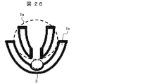
- FIG. 26 shows a structure in which a recess is provided in the structure 1b having no slit in order to widen the dead water area 5. Thereby, the capture rate of the biological substance which passed through the slit can be improved.
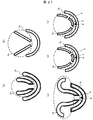
- FIG. 27 shows a modification of the capturing structure.
- FIG. 27A shows the structure 1a having a slit and the structure 1b not having a slit rounded in order to smooth a part of the apex thereof. By rounding, there is an effect such as elimination of fluid flow separation. Since a shape that stabilizes the flow can be realized by utilizing fluid simulation or the like, the slit portion in FIG. 27A can also be streamlined.
- FIG. 27B shows a capturing structure in which a structure 1a having a slit is formed of a part of a triangle.
- the shape of the structure 1a having a slit and the structure 1b having no slit can be formed of a part of an arc, an elliptic arc, or a triangle. Moreover, you may incorporate other shapes, such as a hyperbola, as needed.
- FIG. 27 (c) shows a structure in which two semicircular shapes are added to the structure 1a having a slit so that the biological material 4 can be recovered.
- FIG. 27D shows a case where the structure 1a having slits has two slits. Also in this case, the biological substance 4 can be captured in the dead water area 5.
- the position of the slit 2 is a line-symmetrical position with respect to the structure 1a having the slit, but may be arranged at a position that is not line-symmetrical as shown in FIG. This is effective when, for example, the flow rates of the gaps at the two positions of the structure 1a having a slit and the structure 1b having no slit are different.
Landscapes
- Health & Medical Sciences (AREA)
- Chemical & Material Sciences (AREA)
- Life Sciences & Earth Sciences (AREA)
- Engineering & Computer Science (AREA)
- Biomedical Technology (AREA)
- General Health & Medical Sciences (AREA)
- Physics & Mathematics (AREA)
- Analytical Chemistry (AREA)
- Biochemistry (AREA)
- Wood Science & Technology (AREA)
- Organic Chemistry (AREA)
- Zoology (AREA)
- Bioinformatics & Cheminformatics (AREA)
- Biotechnology (AREA)
- General Physics & Mathematics (AREA)
- Pathology (AREA)
- Immunology (AREA)
- Hematology (AREA)
- Dispersion Chemistry (AREA)
- Molecular Biology (AREA)
- General Engineering & Computer Science (AREA)
- Genetics & Genomics (AREA)
- Microbiology (AREA)
- Sustainable Development (AREA)
- Optics & Photonics (AREA)
- Biophysics (AREA)
- Urology & Nephrology (AREA)
- Food Science & Technology (AREA)
- Medicinal Chemistry (AREA)
- Chemical Kinetics & Catalysis (AREA)
- Clinical Laboratory Science (AREA)
- Apparatus Associated With Microorganisms And Enzymes (AREA)
- Measuring Or Testing Involving Enzymes Or Micro-Organisms (AREA)
- Sampling And Sample Adjustment (AREA)
Abstract
Description
狭い幅のスリットを作製すると製造コストが高くなる。また狭い幅のスリットを用いることで生体関連物質の捕捉率は低くなる。捕捉構造体がスリットを有さない場合には、溶液を送液する前に存在する空気(気泡)を追い出すことが困難となる。
生体関連物質にストレスが加わると、表現形が変わる可能性がある。またスリットに挟まっている生体関連物質に対して、流れ場からのせん断力も発生する。
上記背景技術で説明した方法を用いて、部分的に解決できている課題もあるが全てではない。本発明は、これらの要請全てに応えることのできる分析装置を提供するものである。

マイクロチップの流路内に細菌を捕捉するための構造体を設けておき、細菌を含む溶液を流しながら捕捉する。細菌を含む溶液を必要な量だけ送液できるため、細菌を含む溶液の濃度を調製する必要が無く、非常に希薄な溶液でも使用できる。
スリットで細菌を捕捉する原理ではないため、狭い幅のスリットを作製する必要はない。
1個あたりの捕捉構造体の捕捉率を計算することで、全ての細菌を捕捉する捕捉構造体数を算出できる。
スリットで細菌を捕捉するのではなく、死水域で捕捉するため、外力は加わらない。
#Trapped bacteria (1st column)を1以下にすることで、1つの捕捉構造体に複数の細菌が捕捉されるのを回避できる。
細菌を死水域で捕捉するため、流体からの外力は加わらない。
1.スリットを有する構造体は、スリットを通して、スリットを有さない構造体の流路下流側から流路上流側へ溶液を満たせるため、気泡が除去しやすい。
2.スリットを有する構造体は、スリットの幅などのパラメータを調整することで、死水域を形成できる。
3.スリットを有する構造体は、捕捉構造体同士の間隔、スリットの幅、流速などのパラメータを調整することで、捕捉率を変えることができる。捕捉率を大きくすることで、全ての生体関連物質を捕捉することができる。図1に示したスリット2は1箇所であるが、非特許文献2のように、スリットを複数個設けてもよい。
まず、サンプリングノズル20の洗浄を行う。このときの制御・演算部50による制御の手順を図15に示す。制御・演算部50は、最初にノズル駆動機構を制御して、サンプリングノズル20を洗浄槽68に移動する(S11)。次に、制御・演算部50は、ポンプ65によって洗浄液が循環している洗浄液循環流路66に接続されている第1電磁弁71を制御して開状態にする(S12)。マイクロシリンジ60のプランジャ61は、洗浄中であれば動かしても動かさなくてもよい。この状態では、ポンプ65から圧送された洗浄液が、第1電磁弁71、第1流路62を通ってマイクロシリンジ60に入り、そのままサンプリングノズル20を通ってノズル先端から洗浄槽68内に噴出される。この状態で、ノズル内側の洗浄が行われる。洗浄液としては純水を使用した。
次に、フローセル30の内部を洗浄する。このときの制御・演算部50による制御の手順を図16のフローチャートに示す。
図17のフローチャートを参照して、試薬ラック12中の所定位置の試薬容器11からサンプリングノズル20によって試薬を吸引する手順について説明する。ここで試薬は、細菌を含む溶液として説明する。
図18のフローチャートを参照して、サンプリングノズル20の先端に吸引・保持している試薬をフローセル30に注入する手順について説明する。
次に、検出の手順について、図20のフローチャートを参照して説明する。
次に、分析した細菌の回収手順について、図21のフローチャートを参照して説明する。
1a スリットを有する構造体
1aL スリットを有する構造体の左側
1aR スリットを有する構造体の右側
1b スリットを有さない構造体
2、2a、2b スリット
3、34 流路
4 生体関連物質
5 死水域
11 試薬容器
12 試薬ラック
13 試薬ラック台
14 予混合容器
20 サンプリングノズル
21 ガイドレール
22 直線移動ユニット
23 回転軸
24 アーム
30 フローセル
31 フローセルステージ
32 注入ポート
33 排出ポート
36 上部基板
37 下部基板
38 スペーサ
40 検出ユニット
41 光源
42 撮像装置
50 制御・演算部
51 入力部
52 表示部
53 液面検知部
60 マイクロシリンジ
61 プランジャ
62 第1流路
63 第2流路
64 洗浄液タンク
65 ポンプ
66 洗浄液循環流路
67 流量調節絞り
68 洗浄槽
69 廃液タンク
71 第1電磁弁
72 第2電磁弁
Claims (18)
- 流路と、前記流路に接続された注入口及び排出口とを有する、生体関連物質の分析に用いるフローセルであって、
前記流路内には、前記生体関連物質を捕捉する捕捉構造体が設けられ、前記捕捉構造体は死水域を形成する構造であり、前記死水域に前記生体関連物質を捕捉することを特徴とするフローセル。 - 請求項1において、
前記捕捉構造体は、前記生体関連物質を通すスリットを有するスリット部材と、該スリット部材の下流側に該スリット部材に対向して設けられ、前記生体関連物質を収容する収容部材とを備えていることを特徴とするフローセル。 - 請求項2において、
前記収容部材は、U字型の湾曲形状を有することを特徴とする、フローセル。 - 請求項3において、
前記収容部材は、前記スリットに対向する位置に窪みを有することを特徴とする、フローセル。 - 請求項1において、
前記捕捉構造体は、液が流れる方向及びその方向に直行する方向に行列状に並んでおり、
捕捉構造体は、行方向に等間隔に並んでおり、
偶数行目に配置された隣接する捕捉構造体の略中間に、奇数行目の捕捉構造体が配置されていることを特徴とする、フローセル。 - 請求項1において、
前記捕捉構造体の高さは、前記流路の高さと同じであることを特徴とする、フローセル。 - 請求項1において、
前記捕捉構造体は、一対の平行な曲線波形の構造体であり、この曲線波形は、周期性を持っており、かつ、各周期の波形は対称であり、
一対の構造体の一方は、上端にスリットを有しており、他方は、下端にスリットを有しており、それぞれのスリットは所定の間隔で設けられていることを特徴とする、フローセル。 - 請求項2において、
前記捕捉構造体の捕捉率は下流側に近づくにつれて高くなることを特徴とする、フローセル。 - 請求項8において、
前記捕捉構造体の大きさは、下流側に近づくにつれて大きくなることを特徴とする、フローセル。 - 請求項8において、
前記スリット部材のスリットの間隔は、下流側に近づくにつれて大きくなることを特徴とする、フローセル。 - 請求項8において、
前記捕捉構造体の行方向の数は、下流側に近づくにつれて多くなることを特徴とする、フローセル。 - 流路と、前記流路に接続された注入口及び排出口とを有する、フローセルを用いて生体関連物質の分析を行う分析方法であって、
前記流路内に設けられた、前記生体関連物質を捕捉する捕捉構造体によって死水域を形成し、前記死水域に前記生体関連物質を捕捉する工程を有することを特徴とする分析方法。 - 請求項12において、
前記生体関連物質が細菌、細胞、またはそれらの少なくともいずれか一方と微粒子との結合体のいずれかであることを特徴とする、分析方法。 - 請求項12において、
前記捕捉構造体は、前記生体関連物質を通すスリットを有するスリット部材と、該スリット部材の下流側に該スリット部材に対向して設けられ、前記生体関連物質を収容する収容部材とを備えており、
前記生体関連物質に対して、前記スリットの間隔が大きく、かつ、前記スリット部材と前記収容部材との隙間の間隔よりも大きいことを特徴とする、分析方法。 - 請求項12において、
捕捉した生体関連物質を検出する工程を有することを特徴とする、分析方法。 - 請求項15において、
前記検出する工程では、ラマン、明視野、暗視野、位相差、微分干渉、蛍光、発光、電子顕微鏡のいずれかを用いることを特徴とする、分析方法。 - 請求項15において、
前記検出する工程後に、送液速度、または送液速度と送液方向を変化させて生体関連物質を回収する工程を有することを特徴とする、分析方法。 - 流路及び前記流路に接続された注入口及び排出口を有するフローセルと、
前記注入口からサンプルを注入する注入機構と、
前記フローセル内に捕捉された生体関連物質を検出する検出機構と、を備えた生体関連物質の分析に用いる分析装置であって、
前記流路内には、前記生体関連物質を捕捉する捕捉構造体が設けられ、前記捕捉構造体は死水域を形成する構造であり、前記死水域に前記生体関連物質を捕捉することを特徴とする、分析装置。
Priority Applications (2)
| Application Number | Priority Date | Filing Date | Title |
|---|---|---|---|
| DE112013001375.4T DE112013001375B4 (de) | 2012-04-03 | 2013-03-13 | Durchflusszelle, Analysevorrichtung und Analyseverfahren unter Verwendung derselben |
| US14/390,276 US9429507B2 (en) | 2012-04-03 | 2013-03-13 | Flow cell, analysis equipment and analysis method using same |
Applications Claiming Priority (2)
| Application Number | Priority Date | Filing Date | Title |
|---|---|---|---|
| JP2012084428A JP5965702B2 (ja) | 2012-04-03 | 2012-04-03 | フローセル、これを用いた分析装置、及び分析方法 |
| JP2012-084428 | 2012-04-03 |
Publications (1)
| Publication Number | Publication Date |
|---|---|
| WO2013150869A1 true WO2013150869A1 (ja) | 2013-10-10 |
Family
ID=49300364
Family Applications (1)
| Application Number | Title | Priority Date | Filing Date |
|---|---|---|---|
| PCT/JP2013/056895 Ceased WO2013150869A1 (ja) | 2012-04-03 | 2013-03-13 | フローセル、これを用いた分析装置、及び分析方法 |
Country Status (4)
| Country | Link |
|---|---|
| US (1) | US9429507B2 (ja) |
| JP (1) | JP5965702B2 (ja) |
| DE (1) | DE112013001375B4 (ja) |
| WO (1) | WO2013150869A1 (ja) |
Cited By (1)
| Publication number | Priority date | Publication date | Assignee | Title |
|---|---|---|---|---|
| US12385091B2 (en) | 2019-12-11 | 2025-08-12 | Illumina, Inc. | Immobilization in flow cells |
Families Citing this family (9)
| Publication number | Priority date | Publication date | Assignee | Title |
|---|---|---|---|---|
| JP6303496B2 (ja) * | 2013-12-26 | 2018-04-04 | コニカミノルタ株式会社 | 細胞展開用デバイス |
| JP6688089B2 (ja) * | 2016-01-22 | 2020-04-28 | 日本光電工業株式会社 | フローセルおよび粒子分析装置 |
| USD800001S1 (en) * | 2016-05-09 | 2017-10-17 | Hach Company | Water test strip |
| BR112018075854B1 (pt) * | 2016-11-23 | 2023-05-02 | Illumina, Inc | Sistema e método de fixação de conjunto de células de fluxo |
| US10718786B2 (en) | 2016-11-23 | 2020-07-21 | Illumina, Inc. | Flow cell assembly securement system and method |
| JP7426065B2 (ja) * | 2019-07-17 | 2024-02-01 | 株式会社セルファイバ | 細胞ファイバ製造システム、細胞ファイバ製造方法及びプログラム |
| JP6601931B1 (ja) * | 2019-07-17 | 2019-11-06 | 株式会社セルファイバ | 細胞ファイバ製造システム、細胞ファイバ製造方法及びプログラム |
| JP6848145B2 (ja) * | 2020-11-09 | 2021-03-24 | 株式会社セルファイバ | ファイバ製造システム、ファイバ製造方法及びプログラム |
| WO2025132566A1 (en) * | 2023-12-21 | 2025-06-26 | Boehringer Ingelheim International Gmbh | Measuring arrangement and method for analyzing a fluidic sample |
Family Cites Families (2)
| Publication number | Priority date | Publication date | Assignee | Title |
|---|---|---|---|---|
| WO2007024701A2 (en) | 2005-08-19 | 2007-03-01 | The Regents Of The University Of California | Microfluidic methods for diagnostics and cellular analysis |
| US20110117634A1 (en) | 2008-04-21 | 2011-05-19 | Asaf Halamish | Flat cell carriers with cell traps |
-
2012
- 2012-04-03 JP JP2012084428A patent/JP5965702B2/ja not_active Expired - Fee Related
-
2013
- 2013-03-13 US US14/390,276 patent/US9429507B2/en not_active Expired - Fee Related
- 2013-03-13 DE DE112013001375.4T patent/DE112013001375B4/de not_active Expired - Fee Related
- 2013-03-13 WO PCT/JP2013/056895 patent/WO2013150869A1/ja not_active Ceased
Non-Patent Citations (5)
| Title |
|---|
| "Shisui", IWANAMI RIKAGAKU JITEN, 5TH EDITION, 10 November 2003 (2003-11-10), pages 588 * |
| FALEY, S.L. ET AL.: "Cell chip array for microfluidic proteomics enabling rapid in situ assessment of intracellular protein phosphorylation", BIOMICROFLUIDICS, vol. 5, no. 2, June 2011 (2011-06-01), pages 024106-1 - 024106-7 * |
| KIM, M.C. ET AL.: "Building a better cell trap: Applying Lagrangian modeling to the design of microfluidic devices for cell biology", JOURNAL OF APPLIED PHYSICS, vol. 103, no. 4, 15 February 2008 (2008-02-15), pages 044701-1 - 044701-6, XP012109386, DOI: doi:10.1063/1.2840059 * |
| LUTZ, B.R. ET AL.: "Hydrodynamic tweezers: 1. Noncontact trapping of single cells using steady streaming microeddies", ANALYTICAL CHEMISTRY, vol. 78, no. 15, 1 August 2006 (2006-08-01), pages 5429 - 5435 * |
| NILSSON, J. ET AL.: "Review of cell and particle trapping in microfluidic systems", ANALYTICA CHIMICA ACTA, vol. 649, no. 2, 7 September 2009 (2009-09-07), pages 141 - 157, XP026497473, DOI: doi:10.1016/j.aca.2009.07.017 * |
Cited By (1)
| Publication number | Priority date | Publication date | Assignee | Title |
|---|---|---|---|---|
| US12385091B2 (en) | 2019-12-11 | 2025-08-12 | Illumina, Inc. | Immobilization in flow cells |
Also Published As
| Publication number | Publication date |
|---|---|
| DE112013001375B4 (de) | 2015-12-03 |
| JP2013212086A (ja) | 2013-10-17 |
| JP5965702B2 (ja) | 2016-08-10 |
| DE112013001375T5 (de) | 2014-11-27 |
| US9429507B2 (en) | 2016-08-30 |
| US20150072350A1 (en) | 2015-03-12 |
Similar Documents
| Publication | Publication Date | Title |
|---|---|---|
| JP5965702B2 (ja) | フローセル、これを用いた分析装置、及び分析方法 | |
| US8263387B2 (en) | Sheath flow devices and methods | |
| US8831783B2 (en) | Biochemical processing apparatus | |
| CN108139418B (zh) | 受试体处理芯片、受试体处理装置及受试体处理方法 | |
| KR20180015238A (ko) | 시스템들 및 방법들 | |
| US11047776B2 (en) | Liquid sending method using sample processing chip and liquid sending device for sample processing chip | |
| JPWO2008096776A1 (ja) | 容器反復利用磁性粒子並行処理装置および容器反復利用磁性粒子並行処理方法 | |
| JP6124285B2 (ja) | 循環がん細胞捕捉装置 | |
| JPWO2017183298A1 (ja) | 核酸分析装置 | |
| JPWO2017061620A1 (ja) | 検体処理チップ、検体処理装置および検体処理方法 | |
| JP2021192059A (ja) | 試料処理装置及び試料吸引方法 | |
| US7754476B2 (en) | Biochemical reaction cartridge | |
| US11249100B2 (en) | Modular robotic systems for delivering fluid to microfluidic devices | |
| CN117030421A (zh) | 使用调制气体射流的非接触式混合 | |
| JPWO2017203744A1 (ja) | 核酸検査装置 | |
| KR101204221B1 (ko) | 바이오칩을 이용한 스탬핑 장치 및 그 작동방법 | |
| JP2008139096A (ja) | 生化学反応カートリッジの検査方法および検査装置と生化学処理装置 | |
| JP2017138174A (ja) | 処理ヘッド並びに分析用チップの処理装置および処理方法 | |
| JP2019158794A (ja) | 検体処理方法、検体処理チップおよび検体処理装置 | |
| KR101312090B1 (ko) | 랩온어칩 및 그 구동방법 | |
| JP2006333783A (ja) | 生化学反応カートリッジ、生化学反応装置および生化学反応カートリッジと生化学反応装置を用いた生化学反応検査システム | |
| CN117120170A (zh) | 微流体装置和过程 |
Legal Events
| Date | Code | Title | Description |
|---|---|---|---|
| 121 | Ep: the epo has been informed by wipo that ep was designated in this application |
Ref document number: 13771880 Country of ref document: EP Kind code of ref document: A1 |
|
| WWE | Wipo information: entry into national phase |
Ref document number: 1120130013754 Country of ref document: DE Ref document number: 112013001375 Country of ref document: DE |
|
| WWE | Wipo information: entry into national phase |
Ref document number: 14390276 Country of ref document: US |
|
| 122 | Ep: pct application non-entry in european phase |
Ref document number: 13771880 Country of ref document: EP Kind code of ref document: A1 |