WO2013150797A1 - Heat-source-cooling device - Google Patents
Heat-source-cooling device Download PDFInfo
- Publication number
- WO2013150797A1 WO2013150797A1 PCT/JP2013/002332 JP2013002332W WO2013150797A1 WO 2013150797 A1 WO2013150797 A1 WO 2013150797A1 JP 2013002332 W JP2013002332 W JP 2013002332W WO 2013150797 A1 WO2013150797 A1 WO 2013150797A1
- Authority
- WO
- WIPO (PCT)
- Prior art keywords
- cooling water
- water pump
- heat source
- cooling
- fuel cell
- Prior art date
Links
Images


Classifications
-
- F—MECHANICAL ENGINEERING; LIGHTING; HEATING; WEAPONS; BLASTING
- F01—MACHINES OR ENGINES IN GENERAL; ENGINE PLANTS IN GENERAL; STEAM ENGINES
- F01P—COOLING OF MACHINES OR ENGINES IN GENERAL; COOLING OF INTERNAL-COMBUSTION ENGINES
- F01P7/00—Controlling of coolant flow
- F01P7/14—Controlling of coolant flow the coolant being liquid
- F01P7/16—Controlling of coolant flow the coolant being liquid by thermostatic control
-
- B—PERFORMING OPERATIONS; TRANSPORTING
- B60—VEHICLES IN GENERAL
- B60L—PROPULSION OF ELECTRICALLY-PROPELLED VEHICLES; SUPPLYING ELECTRIC POWER FOR AUXILIARY EQUIPMENT OF ELECTRICALLY-PROPELLED VEHICLES; ELECTRODYNAMIC BRAKE SYSTEMS FOR VEHICLES IN GENERAL; MAGNETIC SUSPENSION OR LEVITATION FOR VEHICLES; MONITORING OPERATING VARIABLES OF ELECTRICALLY-PROPELLED VEHICLES; ELECTRIC SAFETY DEVICES FOR ELECTRICALLY-PROPELLED VEHICLES
- B60L1/00—Supplying electric power to auxiliary equipment of vehicles
- B60L1/003—Supplying electric power to auxiliary equipment of vehicles to auxiliary motors, e.g. for pumps, compressors
-
- B—PERFORMING OPERATIONS; TRANSPORTING
- B60—VEHICLES IN GENERAL
- B60L—PROPULSION OF ELECTRICALLY-PROPELLED VEHICLES; SUPPLYING ELECTRIC POWER FOR AUXILIARY EQUIPMENT OF ELECTRICALLY-PROPELLED VEHICLES; ELECTRODYNAMIC BRAKE SYSTEMS FOR VEHICLES IN GENERAL; MAGNETIC SUSPENSION OR LEVITATION FOR VEHICLES; MONITORING OPERATING VARIABLES OF ELECTRICALLY-PROPELLED VEHICLES; ELECTRIC SAFETY DEVICES FOR ELECTRICALLY-PROPELLED VEHICLES
- B60L3/00—Electric devices on electrically-propelled vehicles for safety purposes; Monitoring operating variables, e.g. speed, deceleration or energy consumption
- B60L3/0023—Detecting, eliminating, remedying or compensating for drive train abnormalities, e.g. failures within the drive train
- B60L3/0053—Detecting, eliminating, remedying or compensating for drive train abnormalities, e.g. failures within the drive train relating to fuel cells
-
- B—PERFORMING OPERATIONS; TRANSPORTING
- B60—VEHICLES IN GENERAL
- B60L—PROPULSION OF ELECTRICALLY-PROPELLED VEHICLES; SUPPLYING ELECTRIC POWER FOR AUXILIARY EQUIPMENT OF ELECTRICALLY-PROPELLED VEHICLES; ELECTRODYNAMIC BRAKE SYSTEMS FOR VEHICLES IN GENERAL; MAGNETIC SUSPENSION OR LEVITATION FOR VEHICLES; MONITORING OPERATING VARIABLES OF ELECTRICALLY-PROPELLED VEHICLES; ELECTRIC SAFETY DEVICES FOR ELECTRICALLY-PROPELLED VEHICLES
- B60L58/00—Methods or circuit arrangements for monitoring or controlling batteries or fuel cells, specially adapted for electric vehicles
- B60L58/30—Methods or circuit arrangements for monitoring or controlling batteries or fuel cells, specially adapted for electric vehicles for monitoring or controlling fuel cells
- B60L58/31—Methods or circuit arrangements for monitoring or controlling batteries or fuel cells, specially adapted for electric vehicles for monitoring or controlling fuel cells for starting of fuel cells
-
- B—PERFORMING OPERATIONS; TRANSPORTING
- B60—VEHICLES IN GENERAL
- B60L—PROPULSION OF ELECTRICALLY-PROPELLED VEHICLES; SUPPLYING ELECTRIC POWER FOR AUXILIARY EQUIPMENT OF ELECTRICALLY-PROPELLED VEHICLES; ELECTRODYNAMIC BRAKE SYSTEMS FOR VEHICLES IN GENERAL; MAGNETIC SUSPENSION OR LEVITATION FOR VEHICLES; MONITORING OPERATING VARIABLES OF ELECTRICALLY-PROPELLED VEHICLES; ELECTRIC SAFETY DEVICES FOR ELECTRICALLY-PROPELLED VEHICLES
- B60L58/00—Methods or circuit arrangements for monitoring or controlling batteries or fuel cells, specially adapted for electric vehicles
- B60L58/30—Methods or circuit arrangements for monitoring or controlling batteries or fuel cells, specially adapted for electric vehicles for monitoring or controlling fuel cells
- B60L58/32—Methods or circuit arrangements for monitoring or controlling batteries or fuel cells, specially adapted for electric vehicles for monitoring or controlling fuel cells for controlling the temperature of fuel cells, e.g. by controlling the electric load
- B60L58/33—Methods or circuit arrangements for monitoring or controlling batteries or fuel cells, specially adapted for electric vehicles for monitoring or controlling fuel cells for controlling the temperature of fuel cells, e.g. by controlling the electric load by cooling
-
- B—PERFORMING OPERATIONS; TRANSPORTING
- B60—VEHICLES IN GENERAL
- B60W—CONJOINT CONTROL OF VEHICLE SUB-UNITS OF DIFFERENT TYPE OR DIFFERENT FUNCTION; CONTROL SYSTEMS SPECIALLY ADAPTED FOR HYBRID VEHICLES; ROAD VEHICLE DRIVE CONTROL SYSTEMS FOR PURPOSES NOT RELATED TO THE CONTROL OF A PARTICULAR SUB-UNIT
- B60W10/00—Conjoint control of vehicle sub-units of different type or different function
- B60W10/28—Conjoint control of vehicle sub-units of different type or different function including control of fuel cells
-
- H—ELECTRICITY
- H01—ELECTRIC ELEMENTS
- H01M—PROCESSES OR MEANS, e.g. BATTERIES, FOR THE DIRECT CONVERSION OF CHEMICAL ENERGY INTO ELECTRICAL ENERGY
- H01M8/00—Fuel cells; Manufacture thereof
- H01M8/04—Auxiliary arrangements, e.g. for control of pressure or for circulation of fluids
- H01M8/04007—Auxiliary arrangements, e.g. for control of pressure or for circulation of fluids related to heat exchange
- H01M8/04029—Heat exchange using liquids
-
- B—PERFORMING OPERATIONS; TRANSPORTING
- B60—VEHICLES IN GENERAL
- B60K—ARRANGEMENT OR MOUNTING OF PROPULSION UNITS OR OF TRANSMISSIONS IN VEHICLES; ARRANGEMENT OR MOUNTING OF PLURAL DIVERSE PRIME-MOVERS IN VEHICLES; AUXILIARY DRIVES FOR VEHICLES; INSTRUMENTATION OR DASHBOARDS FOR VEHICLES; ARRANGEMENTS IN CONNECTION WITH COOLING, AIR INTAKE, GAS EXHAUST OR FUEL SUPPLY OF PROPULSION UNITS IN VEHICLES
- B60K11/00—Arrangement in connection with cooling of propulsion units
- B60K11/02—Arrangement in connection with cooling of propulsion units with liquid cooling
- B60K11/04—Arrangement or mounting of radiators, radiator shutters, or radiator blinds
-
- B—PERFORMING OPERATIONS; TRANSPORTING
- B60—VEHICLES IN GENERAL
- B60L—PROPULSION OF ELECTRICALLY-PROPELLED VEHICLES; SUPPLYING ELECTRIC POWER FOR AUXILIARY EQUIPMENT OF ELECTRICALLY-PROPELLED VEHICLES; ELECTRODYNAMIC BRAKE SYSTEMS FOR VEHICLES IN GENERAL; MAGNETIC SUSPENSION OR LEVITATION FOR VEHICLES; MONITORING OPERATING VARIABLES OF ELECTRICALLY-PROPELLED VEHICLES; ELECTRIC SAFETY DEVICES FOR ELECTRICALLY-PROPELLED VEHICLES
- B60L2240/00—Control parameters of input or output; Target parameters
- B60L2240/10—Vehicle control parameters
- B60L2240/36—Temperature of vehicle components or parts
-
- B—PERFORMING OPERATIONS; TRANSPORTING
- B60—VEHICLES IN GENERAL
- B60L—PROPULSION OF ELECTRICALLY-PROPELLED VEHICLES; SUPPLYING ELECTRIC POWER FOR AUXILIARY EQUIPMENT OF ELECTRICALLY-PROPELLED VEHICLES; ELECTRODYNAMIC BRAKE SYSTEMS FOR VEHICLES IN GENERAL; MAGNETIC SUSPENSION OR LEVITATION FOR VEHICLES; MONITORING OPERATING VARIABLES OF ELECTRICALLY-PROPELLED VEHICLES; ELECTRIC SAFETY DEVICES FOR ELECTRICALLY-PROPELLED VEHICLES
- B60L2260/00—Operating Modes
- B60L2260/20—Drive modes; Transition between modes
- B60L2260/22—Standstill, e.g. zero speed
-
- F—MECHANICAL ENGINEERING; LIGHTING; HEATING; WEAPONS; BLASTING
- F01—MACHINES OR ENGINES IN GENERAL; ENGINE PLANTS IN GENERAL; STEAM ENGINES
- F01P—COOLING OF MACHINES OR ENGINES IN GENERAL; COOLING OF INTERNAL-COMBUSTION ENGINES
- F01P11/00—Component parts, details, or accessories not provided for in, or of interest apart from, groups F01P1/00 - F01P9/00
- F01P11/02—Liquid-coolant filling, overflow, venting, or draining devices
- F01P11/029—Expansion reservoirs
-
- F—MECHANICAL ENGINEERING; LIGHTING; HEATING; WEAPONS; BLASTING
- F01—MACHINES OR ENGINES IN GENERAL; ENGINE PLANTS IN GENERAL; STEAM ENGINES
- F01P—COOLING OF MACHINES OR ENGINES IN GENERAL; COOLING OF INTERNAL-COMBUSTION ENGINES
- F01P2031/00—Fail safe
- F01P2031/30—Cooling after the engine is stopped
-
- Y—GENERAL TAGGING OF NEW TECHNOLOGICAL DEVELOPMENTS; GENERAL TAGGING OF CROSS-SECTIONAL TECHNOLOGIES SPANNING OVER SEVERAL SECTIONS OF THE IPC; TECHNICAL SUBJECTS COVERED BY FORMER USPC CROSS-REFERENCE ART COLLECTIONS [XRACs] AND DIGESTS
- Y02—TECHNOLOGIES OR APPLICATIONS FOR MITIGATION OR ADAPTATION AGAINST CLIMATE CHANGE
- Y02E—REDUCTION OF GREENHOUSE GAS [GHG] EMISSIONS, RELATED TO ENERGY GENERATION, TRANSMISSION OR DISTRIBUTION
- Y02E60/00—Enabling technologies; Technologies with a potential or indirect contribution to GHG emissions mitigation
- Y02E60/30—Hydrogen technology
- Y02E60/50—Fuel cells
-
- Y—GENERAL TAGGING OF NEW TECHNOLOGICAL DEVELOPMENTS; GENERAL TAGGING OF CROSS-SECTIONAL TECHNOLOGIES SPANNING OVER SEVERAL SECTIONS OF THE IPC; TECHNICAL SUBJECTS COVERED BY FORMER USPC CROSS-REFERENCE ART COLLECTIONS [XRACs] AND DIGESTS
- Y02—TECHNOLOGIES OR APPLICATIONS FOR MITIGATION OR ADAPTATION AGAINST CLIMATE CHANGE
- Y02T—CLIMATE CHANGE MITIGATION TECHNOLOGIES RELATED TO TRANSPORTATION
- Y02T90/00—Enabling technologies or technologies with a potential or indirect contribution to GHG emissions mitigation
- Y02T90/40—Application of hydrogen technology to transportation, e.g. using fuel cells
Definitions
- the present disclosure relates to a heat source cooling apparatus having an electric cooling water pump for flowing heat from a heat source that generates traveling energy of a vehicle to dissipate heat to the radiator via the cooling water.
- the present invention relates to a heat source cooling device for a vehicle in which a drive energy generating device composed of an engine of a fuel cell or a hybrid vehicle may stop even during traveling like a fuel cell vehicle or a hybrid vehicle.
- a well-known mechanical or electric cooling water pump stops water supply when the vehicle stops and the engine also stops. That is, whether or not the temperature of the cooling water exceeds a predetermined temperature, the cooling water pump is stopped together with the engine. Further, since the engine is operating while the vehicle is running, the cooling water pump does not stop.
- the temperature of the cooling water rises to about 95 ° C when climbing.
- the electric fan (radiator fan) of the radiator is stopped, and the cooling water pump is stopped, the fuel cell stack power generation efficiency will be improved when the fuel cell vehicle is restarted. There was a problem of lowering.
- the drive energy generation device composed of a fuel cell or the drive energy generation device composed of an engine of a hybrid vehicle may stop even during traveling.
- the stack power generation efficiency of the fuel cell and the operating efficiency of the engine are reduced when the fuel cell and the engine are restarted.
- the cause of the above problem is cavitation.
- An object of the present disclosure is to provide a heat source cooling device that suppresses the occurrence of cavitation in a cooling water pump when the driving energy generating device of a vehicle traveling with the energy of the driving energy generating device is stopped or restarted after the output is reduced. It is in.
- a heat source cooling device includes an electric cooling water pump, a heat source that is cooled by cooling water discharged from the cooling water pump, and that is used as a driving energy generation device that generates traveling energy of the vehicle, and a heat source A radiator that radiates the cooling water heated by the cooling water circuit, a cooling water circuit that connects the cooling water pump, the heat source, and the radiator in a ring shape, and cooling water flows from the cooling water circuit or cools to the cooling water circuit
- a reserve tank that flows out water and a reserve tank inlet valve that controls inflow of cooling water into the reserve tank and outflow of cooling water from the reserve tank are provided.
- the heat source cooling device is a cooling system in which the operation of the cooling water pump is continued until the temperature of the cooling water is cooled below a predetermined temperature when the operation of the heat source is considered to be stopped or stopped and the temperature of the cooling water exceeds a predetermined temperature.
- a water pump operation continuation unit is provided.
- the heat generated by the heat source by rotating the cooling water pump can be cooled by the radiator.
- the cooling water in a cooling water circuit is withdrawn into / out of a reserve tank via a reserve tank inlet valve.
- the pressure difference between the pressure on the discharge side of the cooling water pump and the pressure on the suction side of the cooling water pump increases as the number of rotations of the cooling water pump increases, but the pressure of the cooling water controlled by the reserve tank inlet valve is The pressure is kept lower than the intermediate pressure between the pressure on the discharge side of the cooling water pump and the pressure on the suction side of the cooling water pump.
- Cooling water is sent to a radiator (radiator) by an electric cooling water pump and cooled.
- a radiator radiator
- the discharge flow rate of the cooling water pump is disturbed, making it impossible to operate the heat source with high efficiency.
- Cavitation is generated by rotating the impeller of the cooling water pump at a high speed when the pressure on the suction side of the cooling water pump is decreasing. In order to prevent this cavitation, it is desirable to set the cooling water pressure high.
- ⁇ It is a radiator that prevents the heat source from overheating. Cooling water circulates in the radiator, and the heat source is cooled so that the heat source does not exceed a certain temperature. In general, the cooling water has a property that does not freeze at 0 ° C. or less as is called “antifreeze”, but its boiling point is 100 ° C., which is the same as ordinary water.
- the heat source becomes very hot, if the cooling water is used as it is, it will boil and vaporize, and will soon disappear. Therefore, the cooling water circuit including the radiator is sealed. By making the space closed, even if the cooling water is about to expand due to the heat of the heat source, the space is limited, so that the pressure of the liquid increases and as a result the boiling point increases. In other words, it will not boil at 100 ° C.
- This reserve tank inlet valve is generally known as a radiator cap.
- the reserve tank inlet valve controls the inflow and outflow of the cooling water to the reserve tank.
- the reserve tank inlet valve is pressurized so that the cooling water does not boil at 100 ° C.
- the reserve tank inlet valve having a pressure valve and a vacuum valve is pressed down to a certain pressure by the force of the valve spring.
- a certain pressure is exceeded, the force of the valve spring is overcome, and cooling water flows into the reserve tank by the amount expanded by pushing up the spring.
- the temperature of the heat source rises immediately after the fuel flow is cut off, rather than during driving. For this reason, it is recommended to perform cool-down running after overuse of the heat source. However, depending on the situation, such cool-down driving is not realistic.
- the cooling water pressure controlled by the reserve tank inlet valve is slightly lower than the position of the cooling water circuit that takes an intermediate value between the discharge pressure of the cooling water pump and the suction pressure of the cooling water pump when the cooling water pump is driven.
- a reserve tank inlet valve is installed on the suction side of the pump. Generally, it is provided as a radiator cap at a radiator inlet on the suction side of the cooling water pump.
- the cooling water pump controlled by the reserve tank inlet valve is slightly less than the position of the cooling water circuit that takes an intermediate value between the discharge pressure of the cooling water pump and the suction pressure of the cooling water pump when the cooling water pump is driven.
- a reserve tank inlet valve is installed near the coolant pump discharge side, for example, in the vicinity of the coolant pump discharge port, from the position of the coolant circuit taking the intermediate value, the high pressure cooling just increased by the coolant pump Water is discharged into the reserve tank, and the cooling water cannot be kept at an ideal high pressure.
- cavitation can be suppressed by installing a reserve tank inlet valve so that the reference pressure is close to the inlet of the cooling water pump.
- a reserve tank inlet valve so that the reference pressure is close to the inlet of the cooling water pump.
- a cooling water pump (also called a water pump or W / P) 1 is an electric pump and has an impeller driven by an electric motor.
- the electric cooling water pump 1 is controlled by an ECU (electronic control unit) (not shown) so that the rotational speed increases in order to ensure heat radiation performance when the coolant temperature increases.
- ECU electronic control unit
- a fuel cell also referred to as an FC stack
- a fuel cell sensor 3 used as an example of a heat source 2 or a driving energy generator are provided.
- the cooling water circulates through the heat source 2 to cool the heat source 2.
- the heat source 2 generates traveling energy of the vehicle.
- the temperature of the cooling water that has passed through the heat source 2 is measured by a temperature sensor in the fuel cell sensor 3.
- the flow path is switched between a bypass flow path 5 and a heat radiation passage 7 that passes through a radiator (also referred to as a radiator) by a rotary valve that constitutes the switching valve 4.
- the cooling water can be supplied to both the bypass flow path 5 and the heat radiation path 7 at a predetermined ratio. Since the switching valve 4 allows the cooling water to flow through the bypass passage 5 bypassing the radiator 6 or only through the radiator 6, it contributes to stabilization of the cooling water temperature.
- the radiator 6 radiates the cooling water heated by the heat source 2.
- the cooling water circuit 8 is formed by a pipe connecting at least the cooling water pump 1, the heat source 2, and the radiator 6 in an annular shape.
- a radiator cap is provided which serves as a reserve tank inlet valve 10 for controlling the inflow and outflow of the cooling water to the reserve tank 9.
- the pressure of the cooling water controlled by the reserve tank inlet valve 10 is more than the position of the cooling water circuit 8 which takes an intermediate value between the discharge pressure of the cooling water pump 1 and the pressure of the suction portion of the cooling water pump 1 when the cooling water pump is driven.
- a reserve tank inlet valve 10 is slightly installed on the suction side of the cooling water pump 1. This will be described with reference to FIG.
- FIG. 2 shows changes in the pressure characteristics of the cooling water pump 1 shown in FIG. 1 and the internal pressure of the reserve tank inlet valve 10, particularly the cap internal pressure Pc of the radiator cap.
- the rotation speed (W / P rotation speed) of the cooling water pump 1 (W / P pump 1) increases, the pressure Pin of the cooling water pump 1 and the pressure Pout on the discharge side differ from each other. Expands.
- the characteristics Pc1, Pc2, and Pc3 of the internal pressure Pc of the well-known reserve tank inlet valve 10 a characteristic that drops as the number of revolutions of the cooling water pump 1 increases is selected as in the characteristic Pc3.
- FIG. 3 shows the radiator cap 10 that forms the reserve tank inlet valve 10.
- FIG. 4 shows the operating characteristics of the reserve tank inlet valve 10.
- the reserve tank inlet valve 10 includes a valve spring 12 and a pressure valve 13, and is attached to the radiator upper tank 14.
- the cap internal pressure (also simply referred to as internal pressure) Pc is the pressure in the portion of the cooling water circuit 8 that is closest to the reserve tank inlet valve 10 where the pressure is controlled by the reserve tank inlet valve 10 as shown in FIG.
- the cooling water in the reserve tank 9 and the cooling water in the cooling water circuit 8 repeat inflow and outflow. Since the cooling water circuit 8 is a closed space, the pressure rises when cooling water flows from the reserve tank 9. On the other hand, when the cooling water flows into the reserve tank 9, the pressure in the cooling water circuit 8 decreases.
- the cooling water circuit 8 is increased in pressure, it is difficult for the cooling water to escape from the cooling water circuit 8 to the reserve tank 9, so that the number of rotations of the cooling water pump 1 is increased and the cooling water temperature is increased. In this case, the cooling water circuit 8 becomes extremely high pressure. As a result, as described above, the inside of the cooling water circuit 8 becomes too high, resulting in a pressure-resistant problem such as hose breakage. Therefore, even if it replaces with the useless high-pressure reserve tank inlet valve 10, it only places an extra burden on the hoses and seals.
- the reserve tank inlet valve 10 is generally provided as a radiator cap on the inlet side of the radiator 6 further downstream than the switching valve 4, but in an extreme case, as a comparative example As shown in FIG. 5, it is conceivable to provide a reserve tank inlet valve 10 near the suction portion of the cooling water pump 1.
- the suction portion of the cooling water pump 1 is at a pressure where the pressure at the discharge port is reduced due to pressure loss.
- the reserve tank inlet valve 10 is provided near the suction part of the cooling water pump 1, the internal pressure Pc is lowered.
- the region RC3 is reached, and the opportunity for cooling water to flow out from the cooling water circuit 8 to the reserve tank 9 is reduced, and the cooling water circuit 8 becomes high pressure.
- the cooling water circuit 8 is increased in pressure similarly to the case where the cooling water circuit 8 is replaced with the reserve tank inlet valve 10 having a characteristic that the cooling water does not easily escape from the cooling water circuit 8 to the reserve tank 9. Therefore, the cooling water circuit 8 becomes extremely high when the number of rotations of the cooling water pump 1 is increased or the temperature of the cooling water is increased. As a result, as described above, problems with pressure resistance such as breakage of the hose occur.
- a characteristic Pc1 of the internal pressure Pc indicated by a broken line in FIG. 2 indicates a characteristic in which the internal pressure Pc jumps when the number of revolutions of the cooling water pump 1 increases. Selection of the reserve tank inlet valve 10 such as this characteristic Pc1 is avoided because the inside of the cooling water circuit 8 becomes too high, causing problems with pressure resistance such as hose breakage.
- the internal pressure characteristic Pc2 indicated by the one-dot chain line in FIG. 2 indicates that the internal pressure Pc is equal to the discharge pressure of the cooling water pump 1 when the cooling water pump 1 is driven and the cooling water pump 1 even when the cooling water pump 1 is driven.
- the characteristic which becomes constant like the intermediate value Pc2 of the pressure of the suction part.
- a reserve tank inlet valve 10 having a predetermined characteristic is adopted, and the mounting position thereof is set to the discharge pressure of the cooling water pump 1 and the cooling water when the cooling water pressure is driven. That is, the cooling water pump 1 is slightly suctioned from the position of the cooling water circuit 8 that takes the intermediate value Pc2 of the pressure of the suction portion of the pump 1, and has a drooping characteristic such as the characteristic Pc3.
- the internal pressure Pc is decreased as the rotational speed of the cooling water pump 1 increases.
- the pressure in the cooling water circuit 8 rises even if there is an increase in the rotational speed of the cooling water pump 1, a change in ambient temperature, a change in the heat generated by the heat source 2, etc.
- there is no problem of pressure resistance such as breakage of the hose.
- a cooling water pump operation continuation unit is provided that continues the rotation of the cooling water pump 1 until the temperature of the cooling water is cooled below a predetermined temperature regardless of whether the cooling water is stopped. This will be described below.
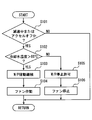
- step S61 when the present control is started, it is determined in step S61 whether or not the power generation amount of the fuel cell serving as the heat source 2 has become a predetermined amount or less.
- the power generation amount may be either a power generation amount or a required power generation amount.
- the power generation amount is shown. For this purpose, it is determined whether or not the amount of power generation has become substantially zero by the current sensor and / or the voltage sensor in the fuel cell sensor 3.
- step S62 it is determined in step S62 whether or not the coolant temperature measured by the temperature sensor in the fuel cell sensor 3 is higher than 85 ° C.
- step S63 If the coolant temperature measured by the temperature sensor is higher than 85 ° C., the operation of the electric coolant pump 1 is continued in step S63.
- the control operation in step S63 may be used as an example of a cooling water pump operation continuation unit. Next, it progresses to step S64 and the electric fan 11 ventilated to the heat radiator 6 is rotated.
- the cooling water pump 1 While the cooling water pump 1 continues to rotate until the temperature of the cooling water is cooled below a predetermined temperature, the cooling water pump 1 discharges 50% or more of the maximum discharge amount of the cooling water pump 1. Discharges cooling water at capacity. According to this, the time until the temperature of the cooling water is cooled to a predetermined temperature or less can be shortened.
- the switching valve 4 in FIG. 1 allows at least a part of the cooling water to flow to the radiator 6 side. According to this, the cooling water can be quickly cooled using the radiator 6.
- the cooling water pump 1 Since the electric fan 11 is operated and the radiator 6 is cooled by the cooling air while the cooling water pump 1 continues to rotate until the temperature of the cooling water is cooled below the predetermined temperature, the cooling water is cooled. The time until the temperature is cooled below the predetermined temperature can be shortened.
- step S65 when the cooling water temperature decreases to 85 ° C. or lower while the power generation amount of the fuel cell (2) is zero, the process proceeds to step S65, and the electric cooling pump 1 is allowed to stop. Therefore, unless the operation of the cooling water pump is requested by other control (including after-mentioned), for example, the control of the vehicle air conditioner that air-conditions the passenger compartment, the operation of the cooling water pump 1 is stopped. In step S66, the rotation of the electric fan 11 is stopped.
- control mode such as the temperature rise control of the FC stack in the fuel cell (2) or the ion recovery control for reducing the ion concentration in the cooling water is also included in the other control.
- a coolant flow rate higher than the amount of power generation may be required.
- the vertical axis represents the rotation speed (W / P rotation speed) of the cooling water pump 1, the cooling water temperature in the cooling water circuit 8, the internal pressure Pc, and the suction side pressure Pin of the cooling water pump 1. The elapsed time on the axis is taken.
- the pressure in the cooling water circuit 8 that is, the system pressure (internal pressure Pc) rises (B).
- Pc system pressure
- a water flow rate is required, and the rotational speed of the cooling water pump 1 increases (C).
- the cooling water flows in the pipe 15 from the cooling water circuit 8 toward the reserve tank 9, and the cooling water flows out to the reserve tank (R / T) 9 (K). Therefore, even if the cooling water temperature rises, the internal pressure Pc is stabilized.
- the vehicle operation key ignition key
- the fuel cell that is the driving energy generation device of the fuel cell vehicle and the heat source 2 is stopped, so that the power generation amount becomes zero.
- a situation occurs (L). The situation so far is the same in both the comparative example and the first embodiment.
- the situation (L) where the fuel cell (2) stops and the amount of power generation becomes zero is not limited to when the vehicle is stopped.
- the other situation where the fuel cell (2) stops and the amount of power generation becomes zero during traveling is that the outside air temperature is as high as 40 ° C when cruising at high speed and high load (160 km / h, etc.)
- the accelerator may be turned off to release the operation of the accelerator, or a downhill condition may be entered.
- the cooling water pump 1 When the fuel cell (2) is stopped and the power generation amount is zero, the cooling water pump 1 is lowered or stopped (M), so that the internal pressure Pc of the reserve tank inlet valve 10 is equalized. Try to rise with it. As a result, it again becomes the control region of the region RC3 in FIG. 4, and the cooling water flows through the pipe 15 from the cooling water circuit 8 toward the reserve tank 9, and the cooling water flows into the reserve tank 9, so that the internal pressure Pc is stabilized.
- Q1 be the amount of cooling water that escapes to the reserve tank 9 at this time (N).
- the driver who has finished the break in such a state restarts the fuel cell (2) and increases the amount of power generation (O). For this reason, the cooling water pump 1 which has been stopped is started and the rotational speed is increased. In this case, the temperature of the cooling water remains at 95 ° C. (P). As the cooling water pump 1 is restarted, the pressure on the suction port side of the cooling water pump 1 is reduced, so that the internal pressure Pc is also reduced. The amount of pressure drop at this time is P1 (Q). Therefore, cavitation occurs in the vicinity of the suction portion of the cooling water pump 1 in accordance with the reduction (R) of the suction pressure of the cooling water pump 1 (S).
- the most extreme example in which the required cooling water flow rate decreases is the vehicle stop condition, but the water temperature is predetermined even under other conditions where the required cooling water flow rate from various requests is reduced. If the value is greater than or equal to the value, control is performed that does not decrease the flow rate of the cooling water pump 1. For this reason, when the power generation amount becomes substantially zero (L), it is determined in step S62 in FIG. 6 whether or not the coolant temperature measured by the temperature sensor is greater than 85 ° C.
- step S63 the operation of the electric cooling water pump 1 is continued (forced cooling) in step S63 (T). Moreover, it progresses to step S64 and the electric fan 11 which ventilates the heat radiator 6 is operated.
- step S65 the cooling water pump 1 stops unless the operation of the cooling water pump 1 is requested by other control.
- step S66 the rotation of the electric fan 11 is stopped.
- the cooling water pump 1 It is controlled so that the rotation speed of the cooling water pump 1 decreases as the cooling water temperature decreases (Ma).
- the cooling water pump 1 is basically stopped as in step S65 of FIG.
- the driver who has finished the break in this state restarts the operation of the fuel cell (2) and increases the power generation amount (O). Therefore, the stopped cooling water pump 1 is started and the rotational speed is increased. In addition, when the operation of the fuel cell (2) is restarted, the cooling water temperature rapidly increases from 85 ° C. to 95 ° C. (Pa). As the rotation of the cooling water pump 1 increases, the pressure at the suction portion of the cooling water pump 1 decreases (Ra), and the internal pressure Pc also decreases. The pressure drop P2 at this time is equivalent to the pressure drop P1 of the comparative example (Qa).
- the weight of the cooling water remaining in the cooling water circuit 8 is the weight of the cooling water according to the first embodiment. Becomes heavier than water.
- the system pressure internal pressure Pc
- the pressure of the suction part of the cooling water pump 1 becomes higher than that of the comparative example, and cavitation can be suppressed (Sa).
- the heat source 2 is a drive energy generation device that may stop even when the vehicle is traveling, and the cooling water pump operation continuation unit (S63) performs cooling while the vehicle is traveling. After the operation of the water pump 1 is continued, the rotation of the cooling water pump 1 is stopped. According to this, in a vehicle that may stop even when the drive energy generation device is running, the efficiency reduction of the drive energy generation device due to cavitation during vehicle running is suppressed, so that the vehicle running performance does not deteriorate. Smooth acceleration is possible.
- the vehicle is composed of a fuel cell vehicle in which the heat source 2 is a fuel cell.
- the rotation of the cooling water pump 1 is stopped after the cooling water pump 1 continues to rotate. This is when the power generation of the fuel cell constituting the heat source 2 is stopped.
- the heat source 2 is composed of a fuel cell. According to this, since the amount of heat generated by the fuel cell is not carried away into the exhaust gas as in the engine (internal combustion engine), even if the overall heat generation amount is smaller than that of the engine, the heat dissipation amount through the cooling water is large. Cooling via cooling water becomes very important. In addition, stabilization of the cooling control greatly affects the efficiency of the fuel cell. In such a situation, the occurrence of cavitation of the cooling water pump 1 can be suppressed, the cooling of the heat source 2 is stabilized, and the operation of the efficient heat source 2 becomes possible.
- the cooling water pump operation continuation unit (S63) is configured such that when the temperature of the cooling water exceeds a predetermined temperature and the amount of heat supplied to the cooling water from the heat source 2 is in a predetermined decrease state, The operation of the cooling water pump 1 is continued until the temperature is cooled below the predetermined temperature, and then the operation of the cooling water pump 1 is stopped.
- the cooling water pump operation continuation unit (S63) cools the temperature of the cooling water to a predetermined temperature or less during traveling of the vehicle in which the amount of heat supplied to the cooling water from the drive energy generator 2 is in a predetermined decreasing state. Until the operation of the cooling water pump 1 is continued, the rotation of the cooling water pump 1 is stopped. Therefore, the operation of the driving energy generator 2 is resumed and the rotation of the cooling water pump 1 is resumed. Therefore, it is possible to suppress a decrease in the pressure of the suction port 1 and to suppress the occurrence of cavitation of the cooling water pump 1. By suppressing the occurrence of cavitation, the cooling of the heat source 2 is stabilized, and an efficient driving energy generator (heat source 2) can be operated.
- heat source 2 an efficient driving energy generator
- the case where the amount of heat supplied to the cooling water from the heat source 2 is in a predetermined decrease state is a case where the required power generation amount of the fuel cell that constitutes the heat source 2 becomes a predetermined value or less. According to this, when the required power generation amount of the fuel cell (2) becomes a predetermined value or less when the temperature of the cooling water exceeds a predetermined temperature, the temperature of the cooling water is maintained at the predetermined temperature even during traveling of the vehicle. Cavitation can be suppressed by stopping the rotation of the cooling water pump after continuing the rotation of the cooling water pump 1 until it is cooled below.
- the case where the amount of heat supplied to the cooling water from the heat source 2 is equal to or less than the predetermined decrease state is a case where the required output of the fuel cell constituting the heat source 2 becomes zero or is regarded as zero. According to this, when the temperature of the cooling water exceeds a predetermined temperature, the required output of the fuel cell becomes zero or is regarded as zero regardless of whether the vehicle is running or stopped.
- the rotation of the cooling water pump 1 can be stopped after the rotation of the cooling water pump 1 is continued until the temperature of the water is cooled below a predetermined temperature, and cavitation can be suppressed.
- the heat source 2 is a fuel cell, and the output current detected by the fuel cell sensor 3 that detects the output current or output voltage of the fuel cell or This is the case when the output voltage reaches zero or is considered zero.
- the heat source 2 is a fuel cell regardless of whether the vehicle is running or stopped, and the output current of the fuel cell detected by the fuel cell sensor 3 or When the output voltage becomes zero or is regarded as zero, the rotation of the cooling water pump 1 is continued until the temperature of the cooling water is cooled below a predetermined temperature even while the vehicle is running. Therefore, the rotation of the cooling water pump 1 can be stopped.
- An electric fan 11 for flowing cooling air to the radiator 6 is provided, and the electric fan 11 is operated while the cooling water pump operation continuation unit (S63) continues to rotate the cooling water pump 1 to cool the radiator 6. Cool with wind.
- the electric fan 11 is operated and the radiator 6 is cooled by the cooling air.
- the time until the cooling water is cooled to a predetermined temperature or less can be shortened.
- the cooling water pump operation continuation unit (S63) continues the rotation of the cooling water pump 1, the cooling water pump 1 has a cooling capacity of 50% or more of the maximum discharge amount of the cooling water pump 1. Is discharged.
- the cooling water has a discharge capacity of 50% or more of the maximum discharge amount of the cooling water pump 1. , The time until the cooling water is cooled to a predetermined temperature or less can be shortened.
- a bypass channel 5 that bypasses the radiator 6 and a switching valve 4 that switches to the bypass channel 5 are provided for the channel through which cooling water flows between the heat source 2 and the radiator 6. According to this, since the cooling water can be made to flow through the bypass flow path 5 that bypasses the radiator 6 by the switching valve 4 or to the radiator 6, it can contribute to stabilization of the cooling water temperature.
- the reserve tank inlet valve 10 is installed in a radiator 6 installed on the suction side of the cooling water pump 1 with respect to the switching valve 4. According to this, the reserve tank inlet valve 10 can be easily configured as a radiator cap.
- step S101 when the fuel cell power generation amount is considered to be substantially zero or zero, the rotation of the cooling water pump 1 is continued until the temperature of the cooling water is cooled below a predetermined temperature.
- step S101 whether or not the accelerator operation is turned off during deceleration of the fuel cell vehicle or during steady running is determined. Judgment. When the accelerator operation is turned off, it is considered that the required power generation amount or the required output of the fuel cell (2) is zero.
- step S102 When the accelerator operation is turned off during vehicle deceleration or steady running in a fuel cell vehicle, it is considered that the required power generation amount has become substantially zero, and the temperature of the cooling water exceeds the predetermined temperature in step S102. If it is determined, the rotation of the cooling water pump 1 is continued in step S103. That is, the control operation in step S103 may be used as an example of a cooling water pump operation continuation unit.
- the other steps S104, S105, and S106 are the same as the corresponding steps in FIG.
- the effects of the second embodiment will be described below.
- the case where the amount of heat supplied to the cooling water from the heat source 2 is in a predetermined decrease state is when the accelerator operation for accelerating the fuel cell vehicle is turned off, or the required power generation amount of the fuel cell constituting the heat source 2 is predetermined. This is when the value falls below the value.
- the accelerator operation for accelerating the fuel cell vehicle is turned off, or the required power generation amount of the fuel cell (2) becomes a predetermined value or less.
- the rotation of the cooling water pump 1 can be stopped after the rotation of the cooling water pump 1 is continued until the temperature of the cooling water is cooled below a predetermined temperature.
- the vehicle is a fuel cell vehicle.
- the vehicle according to the third embodiment is a hybrid vehicle driven by an engine and a battery.
- the engine may be used as an example of the heat source 2.
- step S111 in FIG. 11 it is determined whether or not the engine of the hybrid vehicle has automatically stopped.
- the engine rotation may stop automatically even during traveling. For example, it is a case where the accelerator operation is turned off during vehicle deceleration or steady running. In such a case, if the cavitation of the cooling water pump 1 when engine rotation is resumed is suppressed, the hybrid vehicle can be operated with high efficiency.
- step S111 in FIG. 11 when it is determined in step S111 in FIG. 11 that the engine of the hybrid vehicle has been automatically stopped, the amount of heat supplied to the cooling water from the engine serving as the drive energy generating device is in a predetermined decrease state.
- the cooling water temperature exceeds 85 ° C. in S112
- the rotation of the cooling water pump 1 is continued in step S113 until the cooling water temperature is cooled below a predetermined temperature regardless of whether the vehicle is running or stopped. Then, the rotation of the cooling water pump 1 is stopped. That is, the control operation in step S113 may be used as an example of a cooling water pump operation continuation unit.
- the cooling water pump 1 is electric, unlike the cooling water pump (mechanical pump) that is mechanically driven by the engine (heat source 2), the influence of the rotational speed in the idling state of the engine (2) is affected.
- the cooling water pump 1 is forced to be cooled forcibly with no rotation, the cooling water pump 1 is operated at a discharge capacity of 50% or more of the maximum discharge amount to lower the temperature of the cooling water. As the cooling water temperature decreases, the discharge amount is decreased.
- steps S114, S115, and S116 are the same as the corresponding steps in FIG.
- the vehicle is a hybrid vehicle that is driven by an engine that constitutes the heat source 2 and a battery.
- the rotation of the cooling water pump 1 is stopped after the rotation of the cooling water pump 1 is continued. This is when the engine constituting the heat source 2 is automatically stopped during the operation.
- the cavitation of the cooling water pump 1 is suppressed when the engine rotation is resumed when the engine rotation is automatically stopped even during traveling. High-efficiency operation is possible.
- the cooling water pump operation continuation unit (S113) is configured to run the vehicle when the amount of heat supplied to the cooling water from the engine of the hybrid vehicle serving as the heat source 2 is in a predetermined decreased state when the temperature of the cooling water exceeds a predetermined temperature.
- the rotation of the cooling water pump 1 is stopped after the rotation of the cooling water pump 1 is continued until the temperature of the cooling water is cooled below a predetermined temperature.
- the cooling water pump operation continuation unit (S113) cools the temperature of the cooling water below the predetermined temperature while the vehicle is running in which the amount of heat supplied to the cooling water from the engine of the hybrid vehicle is in a predetermined decreasing state. Until the cooling water pump 1 continues to rotate, the rotation of the cooling water pump 1 is stopped. Therefore, the cooling water pump 1 is restarted when the engine operation is resumed after the engine is automatically stopped and the cooling water pump 1 is resumed. It is possible to suppress a decrease in pressure at the suction port of the cooling water, and to suppress the occurrence of cavitation of the cooling water pump 1. By suppressing the occurrence of cavitation, the cooling of the engine is stabilized and the engine can be operated efficiently.
- the case where the amount of heat supplied to the cooling water from the heat source 2 is equal to or less than the predetermined decrease state is a case where the required output of the engine constituting the heat source 2 becomes zero or is regarded as zero. According to this, when the temperature of the cooling water exceeds a predetermined temperature, regardless of whether the vehicle is running or stopped, if the required output of the engine becomes zero or is regarded as zero, the hybrid vehicle During the traveling, the rotation of the cooling water pump 1 can be stopped after the operation of the cooling water pump 1 is continued until the temperature of the cooling water is cooled below a predetermined temperature.
- the cooling water pump 1 continues to rotate until it is cooled to 85 ° C. or lower, but is cooled until it is cooled to 85 ° C. plus or minus 5 ° C. (85 ° C. to 90 ° C.).
- the rotation of the water pump 1 may be continued. That is, the means for stopping the rotation of the cooling water pump 1 continues the rotation of the cooling water pump 1 until the temperature of the cooling water is cooled to 85 ° C. plus or minus 5 ° C. or less, and then the rotation of the cooling water pump 1. Lower the number.
- the rotation speed of the cooling water pump 1 is decreased after the rotation of the cooling water pump 1 is continued until the temperature of the cooling water is cooled to 85 ° C. plus or minus 5 ° C. or less, the internal pressure Pc of the cooling water is reduced. It is possible to reduce the amount of cooling water flowing into the reserve tank 9, and as a result, cavitation can be prevented.
Abstract
Description
(第1実施形態)
先ず、発明者らが種々の実験により突き止めたことは、燃料電池車等の再始動時に、冷却水ポンプにキャビテーションが発生し、このキャビテーションの発生により、冷却水の燃料電池への供給が不安定になり、燃料電池のスタック発電効率等が低下するという事実である。 Hereinafter, a plurality of modes for carrying out the present disclosure will be described with reference to the drawings. In each embodiment, parts corresponding to the matters described in the preceding embodiment may be denoted by the same reference numerals, and redundant description may be omitted. When only a part of the configuration is described in each mode, the other modes described above can be applied to the other parts of the configuration. Not only combinations of parts that clearly show that combinations are possible in each embodiment, but also combinations of the embodiments even if they are not explicitly stated unless there is a problem with the combination. Is also possible.
(First embodiment)
First, the inventors found out through various experiments that cavitation occurred in the cooling water pump when the fuel cell vehicle or the like was restarted, and the supply of cooling water to the fuel cell was unstable due to the occurrence of this cavitation. This is the fact that the stack power generation efficiency of the fuel cell decreases.
(第2実施形態)
次に、本開示の第2実施形態について説明する。なお、以降の各実施形態においては、上述した第1実施形態と同一の構成要素には同一の符号を付して説明を省略し、異なる構成および特徴について説明する。 While the cooling water pump operation continuation unit (S63) continues the rotation of the cooling
(Second Embodiment)
Next, a second embodiment of the present disclosure will be described. In the following embodiments, the same components as those in the first embodiment described above are denoted by the same reference numerals, description thereof will be omitted, and different configurations and features will be described.
(第3実施形態)
次に、本開示の第3実施形態について説明する。上述した実施形態と異なる特徴部分を説明する。上記第1実施形態においては、車両は燃料電池車であったが、この第3実施形態の車両はエンジンと電池とで駆動されるハイブリッド車からなる。エンジンが熱源2の一例として用いても良い。 According to this, when the temperature of the cooling water exceeds a predetermined temperature, the required output of the engine or the fuel cell (2) becomes zero or is regarded as zero regardless of whether the vehicle is running or stopped. In this case, even while the vehicle is traveling, the rotation of the cooling
(Third embodiment)
Next, a third embodiment of the present disclosure will be described. Features different from the above-described embodiment will be described. In the first embodiment, the vehicle is a fuel cell vehicle. The vehicle according to the third embodiment is a hybrid vehicle driven by an engine and a battery. The engine may be used as an example of the
Claims (14)
- 電動式の冷却水ポンプ(1)と、
前記冷却水ポンプ(1)が吐出する冷却水で冷却され、車両の走行エネルギーを発生する駆動エネルギー発生装置として用いられる熱源(2)と、
前記熱源(2)で加熱された前記冷却水を放熱する放熱器(6)と、
前記冷却水ポンプ(1)、前記熱源(2)、および前記放熱器(6)を環状に連結している冷却水回路(8)と、
前記冷却水回路(8)から前記冷却水が流入する、もしくは前記冷却水回路(8)へ前記冷却水を流出するリザーブタンク(9)と、
前記リザーブタンク(9)への前記冷却水の流入および前記リザーブタンク(9)からの前記冷却水の流出を制御するリザーブタンク入口弁(10)と、を備え、
前記冷却水の圧力が前記冷却水ポンプ駆動時の前記冷却水ポンプ(1)の吐出圧と前記冷却水ポンプ(1)の吸入圧の中間値をとる前記冷却水回路(8)の位置と、前記冷却水ポンプ(1)の吸入側との間に前記リザーブタンク入口弁(10)が設けられ、
前記熱源(2)の運転が停止または停止とみなされ、前記冷却水の温度が所定温度を超える場合に、前記冷却水の温度が所定温度以下に冷却されるまで前記冷却水ポンプ(1)の運転を継続させる冷却水ポンプ運転継続部(S63、S103、S113)を備える熱源冷却装置。 An electric cooling water pump (1);
A heat source (2) used as a driving energy generating device that is cooled by cooling water discharged from the cooling water pump (1) and generates running energy of the vehicle;
A radiator (6) for radiating the cooling water heated by the heat source (2);
A cooling water circuit (8) connecting the cooling water pump (1), the heat source (2), and the radiator (6) in an annular shape;
A reserve tank (9) from which the cooling water flows from the cooling water circuit (8) or from which the cooling water flows out to the cooling water circuit (8);
A reserve tank inlet valve (10) for controlling the inflow of the cooling water to the reserve tank (9) and the outflow of the cooling water from the reserve tank (9),
The position of the cooling water circuit (8) in which the pressure of the cooling water takes an intermediate value between the discharge pressure of the cooling water pump (1) when the cooling water pump is driven and the suction pressure of the cooling water pump (1); The reserve tank inlet valve (10) is provided between the suction side of the cooling water pump (1),
When the operation of the heat source (2) is considered to be stopped or stopped, and the temperature of the cooling water exceeds a predetermined temperature, the cooling water pump (1) of the cooling water pump (1) is cooled until the temperature of the cooling water is cooled below a predetermined temperature. A heat source cooling device including a cooling water pump operation continuation unit (S63, S103, S113) for continuing operation. - 前記熱源(2)は、前記車両が走行中であっても停止させることができる請求項1に記載の熱源冷却装置。 The heat source cooling device according to claim 1, wherein the heat source (2) can be stopped even when the vehicle is running.
- 前記車両は、前記熱源(2)が燃料電池である燃料電池車、または前記熱源(2)がエンジンと電池であるハイブリッド車であり、
前記冷却水ポンプ運転継続部(S63、S103、S113)が、前記冷却水ポンプ(1)の運転を継続させるのは、前記車両の走行中に前記燃料電池の発電が停止された場合、または前記車両の走行中に前記エンジンが自動停止した場合である請求項1または2に記載の熱源冷却装置。 The vehicle is a fuel cell vehicle in which the heat source (2) is a fuel cell, or a hybrid vehicle in which the heat source (2) is an engine and a battery,
The cooling water pump operation continuation unit (S63, S103, S113) continues the operation of the cooling water pump (1) when power generation of the fuel cell is stopped during the traveling of the vehicle, or The heat source cooling device according to claim 1 or 2, wherein the engine is automatically stopped while the vehicle is running. - 前記熱源(2)は、前記燃料電池である請求項3に記載の熱源冷却装置。 The heat source cooling device according to claim 3, wherein the heat source (2) is the fuel cell.
- 前記冷却水ポンプ運転継続部(S63、S103、S113)は、前記熱源(2)からの前記冷却水に対する供給熱量が予め設定された熱量である所定減少状態となる場合または前記所定減少状態になったとみなされる場合に、前記熱源(2)の運転は停止とみなし、
前記冷却水ポンプ運転継続部(S63、S103、S113)は、前記車両の走行中において前記熱源(2)の運転が停止とみなされた場合、前記冷却水の温度が前記所定温度以下に冷却されるまで前記冷却水ポンプ(1)の運転を継続させる請求項1ないし4のいずれか一項に記載の熱源冷却装置。 The cooling water pump operation continuation unit (S63, S103, S113) is in a predetermined decrease state where the amount of heat supplied to the cooling water from the heat source (2) is a preset heat amount or in the predetermined decrease state. The operation of the heat source (2) is considered to be stopped,
The cooling water pump operation continuation unit (S63, S103, S113) cools the temperature of the cooling water below the predetermined temperature when the operation of the heat source (2) is considered to be stopped while the vehicle is running. The heat source cooling device according to any one of claims 1 to 4, wherein the operation of the cooling water pump (1) is continued till - 前記燃料電池車を加速させるアクセルの操作がオフ状態になった場合、または、前記熱源(2)を成す前記燃料電池の要求発電量が所定値以下になった場合に、前記熱源(2)からの前記冷却水に対する供給熱量が前記所定減少状態になったとみなされる請求項5に記載の熱源冷却装置。 When the operation of the accelerator for accelerating the fuel cell vehicle is turned off, or when the required power generation amount of the fuel cell constituting the heat source (2) becomes a predetermined value or less, the heat source (2) The heat source cooling device according to claim 5, wherein the amount of heat supplied to the cooling water is considered to be in the predetermined decrease state.
- 前記熱源(2)を成す前記エンジンまたは前記燃料電池の要求出力がゼロとなった場合またはゼロとなったとみなされた場合に、前記熱源(2)からの前記冷却水に対する供給熱量が前記所定減少状態になったとみなされる請求項5に記載の熱源冷却装置。 When the required output of the engine or the fuel cell constituting the heat source (2) becomes zero or is considered to be zero, the amount of heat supplied to the cooling water from the heat source (2) decreases by the predetermined amount. The heat source cooling device according to claim 5, which is considered to be in a state.
- 更に、前記熱源(2)と成る燃料電池の出力電流または出力電圧を検出する燃料電池センサ(3)を備え、
前記燃料電池センサ(3)で検出された前記出力電流または前記出力電圧がゼロに成った場合、またはゼロとみなされた場合に、前記熱源(2)からの前記冷却水に対する供給熱量が前記所定減少状態以下となる請求項5に記載の熱源冷却装置。 And a fuel cell sensor (3) for detecting an output current or an output voltage of the fuel cell serving as the heat source (2),
When the output current or the output voltage detected by the fuel cell sensor (3) becomes zero or is considered to be zero, the amount of heat supplied to the cooling water from the heat source (2) is the predetermined amount. The heat source cooling device according to claim 5 which becomes below a decrease state. - 前記冷却水ポンプ運転継続部(S63、S103、S113)は、前記冷却水の温度が85℃プラスマイナス5℃以下に冷却されるまで、前記冷却水ポンプ(1)の運転を継続させてから前記冷却水ポンプ(1)を停止する請求項1ないし8のいずれか一項に記載の熱源冷却装置。 The cooling water pump operation continuation unit (S63, S103, S113) continues the operation of the cooling water pump (1) until the temperature of the cooling water is cooled to 85 ° C plus or minus 5 ° C or less. The heat source cooling device according to any one of claims 1 to 8, wherein the cooling water pump (1) is stopped.
- 更に、前記放熱器(6)に冷却風を流す電動ファン(11)を備え、
前記冷却水ポンプ運転継続部(S63、S103、S113)が前記冷却水ポンプ(1)の運転を継続させている間に、前記電動ファン(11)を稼動させ、前記放熱器(6)を前記冷却風で冷却する請求項1ないし9のいずれか一項に記載の熱源冷却装置。 Furthermore, an electric fan (11) for flowing cooling air to the radiator (6) is provided,
While the cooling water pump operation continuation unit (S63, S103, S113) continues the operation of the cooling water pump (1), the electric fan (11) is operated, and the radiator (6) is The heat source cooling device according to any one of claims 1 to 9, wherein cooling is performed by cooling air. - 前記冷却水ポンプ運転継続部(S63、S103、S113)が前記冷却水ポンプ(1)の運転を継続させている間において、前記冷却水ポンプ(1)は、該冷却水ポンプ(1)の最大吐出量の50%以上の吐出能力で前記冷却水を吐出することが可能な請求項1ないし10のいずれか一項に記載の熱源冷却装置。 While the cooling water pump operation continuation unit (S63, S103, S113) continues the operation of the cooling water pump (1), the cooling water pump (1) is the maximum of the cooling water pump (1). The heat source cooling device according to any one of claims 1 to 10, wherein the cooling water can be discharged with a discharge capacity of 50% or more of a discharge amount.
- 前記放熱器(6)をバイパスするバイパス流路(5)と、
該バイパス流路(5)と前記放熱器(6)へ繋がる流路とを切替える切替え弁(4)とを有する請求項1ないし11のいずれか一項に記載の熱源冷却装置。 A bypass channel (5) for bypassing the radiator (6);
The heat source cooling device according to any one of claims 1 to 11, further comprising a switching valve (4) for switching between the bypass channel (5) and a channel connected to the radiator (6). - 前記リザーブタンク入口弁(10)は、前記切替え弁(4)よりも前記冷却水ポンプ(1)の吸入側に設置された前記放熱器(6)に設置されている請求項12に記載の熱源冷却装置。 The heat source according to claim 12, wherein the reserve tank inlet valve (10) is installed in the radiator (6) installed on the suction side of the cooling water pump (1) with respect to the switching valve (4). Cooling system.
- 前記冷却水ポンプ運転継続部(S63、S103、S113)が前記冷却水ポンプ(1)の運転を継続させている間において、前記切替え弁(4)は、前記放熱器(6)側にすくなくとも一部の冷却水を流す請求項12または13に記載の熱源冷却装置。 While the cooling water pump operation continuation unit (S63, S103, S113) continues the operation of the cooling water pump (1), the switching valve (4) is at least one on the radiator (6) side. The heat source cooling device according to claim 12 or 13, wherein the cooling water of the part is allowed to flow.
Priority Applications (3)
| Application Number | Priority Date | Filing Date | Title |
|---|---|---|---|
| US14/390,627 US20150056530A1 (en) | 2012-04-05 | 2013-04-04 | Heat-source cooling device |
| CN201380018586.8A CN104284794B (en) | 2012-04-05 | 2013-04-04 | Heat source refrigerating device |
| DE201311001899 DE112013001899T5 (en) | 2012-04-05 | 2013-04-04 | Heat source Cooler |
Applications Claiming Priority (2)
| Application Number | Priority Date | Filing Date | Title |
|---|---|---|---|
| JP2012-086549 | 2012-04-05 | ||
| JP2012086549A JP5811932B2 (en) | 2012-04-05 | 2012-04-05 | Heat source cooling device |
Publications (1)
| Publication Number | Publication Date |
|---|---|
| WO2013150797A1 true WO2013150797A1 (en) | 2013-10-10 |
Family
ID=49300299
Family Applications (1)
| Application Number | Title | Priority Date | Filing Date |
|---|---|---|---|
| PCT/JP2013/002332 WO2013150797A1 (en) | 2012-04-05 | 2013-04-04 | Heat-source-cooling device |
Country Status (5)
| Country | Link |
|---|---|
| US (1) | US20150056530A1 (en) |
| JP (1) | JP5811932B2 (en) |
| CN (1) | CN104284794B (en) |
| DE (1) | DE112013001899T5 (en) |
| WO (1) | WO2013150797A1 (en) |
Cited By (3)
| Publication number | Priority date | Publication date | Assignee | Title |
|---|---|---|---|---|
| CN103996890A (en) * | 2014-05-26 | 2014-08-20 | 唐山轨道客车有限责任公司 | Heat control system for tramcar |
| CN106159294A (en) * | 2014-11-05 | 2016-11-23 | 现代自动车株式会社 | Control the system and method for the temperature of fuel cell pack |
| CN109904490A (en) * | 2019-03-28 | 2019-06-18 | 武汉泰歌氢能汽车有限公司 | A kind of fuel battery cooling system using organic working medium |
Families Citing this family (13)
| Publication number | Priority date | Publication date | Assignee | Title |
|---|---|---|---|---|
| KR101646372B1 (en) * | 2014-11-03 | 2016-08-12 | 현대자동차주식회사 | Air blower controlling method for fuel cell vehicle |
| DE102015218233A1 (en) * | 2015-09-23 | 2017-03-23 | Bayerische Motoren Werke Aktiengesellschaft | Pressure vessel system for a motor vehicle, motor vehicle and method for interrupting a fluid connection |
| KR101755924B1 (en) | 2015-12-09 | 2017-07-10 | 현대자동차주식회사 | Non-negative pressure radiator cap |
| KR101878025B1 (en) * | 2015-12-11 | 2018-07-16 | 현대자동차주식회사 | Apparatus for protecting negative pressure |
| KR101822245B1 (en) | 2015-12-14 | 2018-01-26 | 현대자동차주식회사 | Control method of cooling pump for fuel cell system |
| JP6759640B2 (en) * | 2016-03-16 | 2020-09-23 | トヨタ自動車株式会社 | Fuel cell system |
| KR101905951B1 (en) * | 2016-04-18 | 2018-10-08 | 현대자동차주식회사 | Starting control method at full cell vehicle |
| CN111129646B (en) * | 2018-11-01 | 2024-04-12 | 伊利诺斯工具制品有限公司 | Cooling system |
| JP7183725B2 (en) * | 2018-11-21 | 2022-12-06 | トヨタ自動車株式会社 | fuel cell system |
| CN109656272B (en) * | 2018-12-11 | 2022-05-17 | 中国航空工业集团公司成都飞机设计研究所 | Heat sink flow control method and device and storage medium |
| CN110671187B (en) * | 2019-09-30 | 2020-10-30 | 潍柴动力股份有限公司 | Cooling control method, control device and control system for engine in vehicle |
| JP2022108685A (en) * | 2021-01-13 | 2022-07-26 | 本田技研工業株式会社 | vehicle |
| CN113217199B (en) * | 2021-04-16 | 2023-07-28 | 联合汽车电子有限公司 | Engine allowable stop judging method and vehicle |
Citations (2)
| Publication number | Priority date | Publication date | Assignee | Title |
|---|---|---|---|---|
| JP2007122962A (en) * | 2005-10-26 | 2007-05-17 | Nissan Motor Co Ltd | Fuel cell system, and antifreezing method of cooling system |
| JP2010059880A (en) * | 2008-09-04 | 2010-03-18 | Toyota Motor Corp | Cooling device for internal combustion engine |
Family Cites Families (12)
| Publication number | Priority date | Publication date | Assignee | Title |
|---|---|---|---|---|
| DE3226509A1 (en) * | 1982-07-15 | 1984-01-26 | Bayerische Motoren Werke AG, 8000 München | COOLING CIRCUIT FOR INTERNAL COMBUSTION ENGINES |
| CA1333196C (en) * | 1987-12-28 | 1994-11-22 | Yasuyuki Aihara | Engine compartment cooling control system |
| JPH02294516A (en) * | 1989-05-09 | 1990-12-05 | Nissan Motor Co Ltd | Cooling device of engine |
| US5241926A (en) * | 1991-08-09 | 1993-09-07 | Mazda Motor Corporation | Engine cooling apparatus |
| DE19508102C1 (en) * | 1995-03-08 | 1996-07-25 | Volkswagen Ag | Method for regulating a cooling circuit of an internal combustion engine, in particular for motor vehicles |
| JP3733550B2 (en) * | 2000-12-05 | 2006-01-11 | 愛三工業株式会社 | Engine cooling system |
| DE10320746A1 (en) * | 2003-05-09 | 2004-12-02 | Daimlerchrysler Ag | Extended fan overrun |
| US6955141B2 (en) * | 2003-08-06 | 2005-10-18 | General Motors Corporation | Engine cooling system |
| SE525988C2 (en) * | 2003-10-24 | 2005-06-07 | Volvo Lastvagnar Ab | Cooling system for a combustion engine mounted in a vehicle |
| JP4306782B2 (en) * | 2007-11-21 | 2009-08-05 | トヨタ自動車株式会社 | Vehicle cooling control apparatus and cooling control method |
| KR101000703B1 (en) * | 2008-07-08 | 2010-12-10 | 현대자동차주식회사 | Idle stop and start control method of fuel cell hybrid vehicle |
| KR101241213B1 (en) * | 2010-12-03 | 2013-03-13 | 기아자동차주식회사 | Electric water pump control system and method thereof |
-
2012
- 2012-04-05 JP JP2012086549A patent/JP5811932B2/en active Active
-
2013
- 2013-04-04 US US14/390,627 patent/US20150056530A1/en not_active Abandoned
- 2013-04-04 CN CN201380018586.8A patent/CN104284794B/en not_active Expired - Fee Related
- 2013-04-04 DE DE201311001899 patent/DE112013001899T5/en active Pending
- 2013-04-04 WO PCT/JP2013/002332 patent/WO2013150797A1/en active Application Filing
Patent Citations (2)
| Publication number | Priority date | Publication date | Assignee | Title |
|---|---|---|---|---|
| JP2007122962A (en) * | 2005-10-26 | 2007-05-17 | Nissan Motor Co Ltd | Fuel cell system, and antifreezing method of cooling system |
| JP2010059880A (en) * | 2008-09-04 | 2010-03-18 | Toyota Motor Corp | Cooling device for internal combustion engine |
Cited By (7)
| Publication number | Priority date | Publication date | Assignee | Title |
|---|---|---|---|---|
| CN103996890A (en) * | 2014-05-26 | 2014-08-20 | 唐山轨道客车有限责任公司 | Heat control system for tramcar |
| WO2015180415A1 (en) * | 2014-05-26 | 2015-12-03 | 唐山轨道客车有限责任公司 | Thermal control system for streetcar |
| CN103996890B (en) * | 2014-05-26 | 2016-02-10 | 唐山轨道客车有限责任公司 | For the thermal control system of tramcar |
| US10320010B2 (en) | 2014-05-26 | 2019-06-11 | Crrc Tangshan Co., Ltd. | Thermal control system for tramcar |
| CN106159294A (en) * | 2014-11-05 | 2016-11-23 | 现代自动车株式会社 | Control the system and method for the temperature of fuel cell pack |
| CN109904490A (en) * | 2019-03-28 | 2019-06-18 | 武汉泰歌氢能汽车有限公司 | A kind of fuel battery cooling system using organic working medium |
| CN109904490B (en) * | 2019-03-28 | 2024-04-09 | 武汉泰歌氢能汽车有限公司 | Fuel cell cooling system adopting organic working medium |
Also Published As
| Publication number | Publication date |
|---|---|
| DE112013001899T5 (en) | 2015-01-08 |
| JP2013216158A (en) | 2013-10-24 |
| US20150056530A1 (en) | 2015-02-26 |
| CN104284794A (en) | 2015-01-14 |
| CN104284794B (en) | 2017-03-01 |
| JP5811932B2 (en) | 2015-11-11 |
Similar Documents
| Publication | Publication Date | Title |
|---|---|---|
| JP5811932B2 (en) | Heat source cooling device | |
| US10232702B2 (en) | Thermal management system | |
| US9199531B2 (en) | Hybrid electric vehicle cooling circuit and method of cooling | |
| US9631547B2 (en) | PHEV heating modes to provide cabin comfort | |
| CN108699945B (en) | Cooling device and control method for internal combustion engine for vehicle | |
| US20130074497A1 (en) | Waste heat recovery system | |
| JP6051984B2 (en) | Thermal management system for vehicles | |
| WO2005113961A1 (en) | Motor-assisted turbo charger for an internal combustion engine | |
| WO2014010159A1 (en) | Cooling system for vehicles | |
| JP2012101616A (en) | Control device of series hybrid vehicle | |
| US7066114B1 (en) | Reverse fan operation for vehicle cooling system | |
| JP6148787B2 (en) | Control device for internal combustion engine and control method for cooling device | |
| KR101294424B1 (en) | Water Cooling type Turbo Charger System and Operation Method thereof | |
| US11884137B2 (en) | Control device for vehicle-mounted cooling system, and vehicle-mounted cooling system | |
| US11597375B2 (en) | Vehicle control device | |
| KR101915990B1 (en) | A combined heat and power generating system and A method for controlling the same | |
| JP7119945B2 (en) | fuel cell system | |
| JP6180185B2 (en) | Vehicle battery heating device | |
| JP2009068398A (en) | Internal combustion engine | |
| JP2005248854A (en) | Cooling device for internal combustion engine | |
| WO2020111004A1 (en) | Vehicle-mounted cooling system control device and vehicle-mounted cooling system | |
| JP6816526B2 (en) | Fuel cell system | |
| EP4155142A1 (en) | A vehicle energy management system, a vehicle comprising such a vehicle energy management system, and a method of controlling a vehicle energy management system | |
| CN117922248A (en) | Temperature control system, temperature control method, and program product for vehicle | |
| JP2014227037A (en) | Battery heating device of vehicle |
Legal Events
| Date | Code | Title | Description |
|---|---|---|---|
| 121 | Ep: the epo has been informed by wipo that ep was designated in this application |
Ref document number: 13772209 Country of ref document: EP Kind code of ref document: A1 |
|
| WWE | Wipo information: entry into national phase |
Ref document number: 14390627 Country of ref document: US |
|
| WWE | Wipo information: entry into national phase |
Ref document number: 1120130018993 Country of ref document: DE Ref document number: 112013001899 Country of ref document: DE |
|
| 122 | Ep: pct application non-entry in european phase |
Ref document number: 13772209 Country of ref document: EP Kind code of ref document: A1 |