WO2013146491A1 - 多層光記録媒体および光記録装置 - Google Patents
多層光記録媒体および光記録装置 Download PDFInfo
- Publication number
- WO2013146491A1 WO2013146491A1 PCT/JP2013/057955 JP2013057955W WO2013146491A1 WO 2013146491 A1 WO2013146491 A1 WO 2013146491A1 JP 2013057955 W JP2013057955 W JP 2013057955W WO 2013146491 A1 WO2013146491 A1 WO 2013146491A1
- Authority
- WO
- WIPO (PCT)
- Prior art keywords
- guide
- management information
- optical
- recording
- optical recording
- Prior art date
- Legal status (The legal status is an assumption and is not a legal conclusion. Google has not performed a legal analysis and makes no representation as to the accuracy of the status listed.)
- Ceased
Links
Images




Classifications
-
- G—PHYSICS
- G11—INFORMATION STORAGE
- G11B—INFORMATION STORAGE BASED ON RELATIVE MOVEMENT BETWEEN RECORD CARRIER AND TRANSDUCER
- G11B7/00—Recording or reproducing by optical means, e.g. recording using a thermal beam of optical radiation by modifying optical properties or the physical structure, reproducing using an optical beam at lower power by sensing optical properties; Record carriers therefor
- G11B7/24—Record carriers characterised by shape, structure or physical properties, or by the selection of the material
- G11B7/2403—Layers; Shape, structure or physical properties thereof
- G11B7/24035—Recording layers
- G11B7/24038—Multiple laminated recording layers
-
- G—PHYSICS
- G11—INFORMATION STORAGE
- G11B—INFORMATION STORAGE BASED ON RELATIVE MOVEMENT BETWEEN RECORD CARRIER AND TRANSDUCER
- G11B7/00—Recording or reproducing by optical means, e.g. recording using a thermal beam of optical radiation by modifying optical properties or the physical structure, reproducing using an optical beam at lower power by sensing optical properties; Record carriers therefor
- G11B7/007—Arrangement of the information on the record carrier, e.g. form of tracks, actual track shape, e.g. wobbled, or cross-section, e.g. v-shaped; Sequential information structures, e.g. sectoring or header formats within a track
- G11B7/00736—Auxiliary data, e.g. lead-in, lead-out, Power Calibration Area [PCA], Burst Cutting Area [BCA], control information
-
- G—PHYSICS
- G11—INFORMATION STORAGE
- G11B—INFORMATION STORAGE BASED ON RELATIVE MOVEMENT BETWEEN RECORD CARRIER AND TRANSDUCER
- G11B7/00—Recording or reproducing by optical means, e.g. recording using a thermal beam of optical radiation by modifying optical properties or the physical structure, reproducing using an optical beam at lower power by sensing optical properties; Record carriers therefor
- G11B7/12—Heads, e.g. forming of the optical beam spot or modulation of the optical beam
- G11B7/14—Heads, e.g. forming of the optical beam spot or modulation of the optical beam specially adapted to record on, or to reproduce from, more than one track simultaneously
-
- G—PHYSICS
- G11—INFORMATION STORAGE
- G11B—INFORMATION STORAGE BASED ON RELATIVE MOVEMENT BETWEEN RECORD CARRIER AND TRANSDUCER
- G11B7/00—Recording or reproducing by optical means, e.g. recording using a thermal beam of optical radiation by modifying optical properties or the physical structure, reproducing using an optical beam at lower power by sensing optical properties; Record carriers therefor
- G11B7/24—Record carriers characterised by shape, structure or physical properties, or by the selection of the material
- G11B7/2403—Layers; Shape, structure or physical properties thereof
- G11B7/24047—Substrates
- G11B7/2405—Substrates being also used as track layers of pre-formatted layers
Definitions
- the present invention relates to an optical recording medium with a guide layer having a guide layer and a plurality of recording layers, a multilayer optical recording medium and an optical recording apparatus for performing recording on the optical recording medium with a guide layer.
- the recording layer is multi-layered.
- track king control at the time of recording or reproducing data on a recording layer is performed using a guide track provided in a layer different from the recording layer.
- tracking control is performed on a guide track layer provided with a guide track having a groove structure using light having a wavelength of 390 nm to 420 nm (blue), and one recording layer among a plurality of recording layers is 650 nm to 680 nm.
- an optical drive device that performs recording using light of the wavelength (red) (for example, Patent Document 1). *
- a system in which data is simultaneously recorded and read by a plurality of optical pickups with respect to a plurality of recording layers provided on the optical disc.
- a CLV Constant Linear Velocity
- a / B side identification information is recorded by prepits in the lead-in area of each recording side. According to the identification information on the A / B surface, when the orientation of the A / B surface is erroneously inserted into the drive device, it is possible to recognize the erroneous insertion of the recording medium on the drive device side (for example, a patent) Literature 3 etc.).
- JP 2007-200197 A Japanese Patent Laid-Open No. 1-134766 Japanese Unexamined Patent Publication No. 2000-251387
- an object of the present invention is to provide a multilayer optical recording medium capable of suppressing a decrease in manufacturing yield due to inability to read management information, and speeding up a discrimination process between a double-sided disc and a single-sided disc, and An optical recording apparatus is provided.
- a multilayer optical recording medium is provided with a plurality of recording layers capable of recording information and a guide track for tracking, and management information is provided along the guide track.
- Two optical recording media with a guide layer having a guide layer having a pre-recorded lead-in area are bonded together to form a double-sided disc capable of recording on both sides, and the management information is Side surface identification information for identifying the side surface of the double-sided disc is included.
- the management information including the side surface identification information for identifying the side surface of the double-sided disc is recorded in advance in the lead-in area of the guide layer, so that the surface management information is recorded on the recording layer.
- the probability of occurrence of defective products due to the inability to read surface information can be reduced, and the production yield can be improved.
- An optical recording apparatus is provided with a plurality of recording layers capable of recording information, a guide track for tracking, and a lead-in area in which management information is recorded in advance along the guide track
- the two optical recording media with guide layers having the guide layer are laminated together so as to form a double-sided disc capable of recording on both sides, and the management information is stored on the side surface of the double-sided disc.
- An optical recording apparatus capable of recording on a multilayer optical recording medium including side surface identification information for identification, provided corresponding to one of the optical recording media with a guide layer of the multilayer optical recording medium,
- a first optical pickup having a first guide optical system for condensing first guide light on the guide layer of the optical recording medium with a guide layer and receiving the reflected light; and the multilayer
- the second guide light is provided corresponding to the other optical recording medium with the guide layer of the recording medium, and the second guide light is condensed on the guide layer of the other optical recording medium with the guide layer, and the reflected light is received.
- a second optical pickup having two guide optical systems, and the one guide layer of the multilayer recording medium with one guide layer based on the first guide light received by the first guide optical system.
- the recorded management information is reproduced as first management information, and the other guide layer-equipped multi-layer recording medium based on the second guide light received by the second guide optical system is used.
- a management information reproducing unit that reproduces the management information recorded in the guide layer as second management information, and the side management information included in each of the reproduced first management information and second management information.
- the side surface identification information for identifying the side surface of the double-sided disc is respectively determined from the lead-in area of the guide layer of each of the optical recording media with guide layers on both sides of the double-sided disc.
- One management information and second management information can be read.
- the control unit correlates the first optical pickup and the second optical pickup with the side surfaces of the double-sided disc based on the side surface identification information included in the first management information and the second management information, respectively.
- An optical recording apparatus wherein the multilayer optical recording medium is used alone as a first multilayer optical recording medium, and the optical recording medium with a guide layer is used as a single-sided disk capable of recording on one side, and the management information
- a multi-layer optical recording medium including single-side disc identification information for identifying the single-side disc as a second multi-layer optical recording medium can be alternatively set.
- the surface management information reproducing unit reproduces the management information based on guide light received by one of the first optical pickup and the second optical pickup
- the controller controls the other of the first optical pickup and the second optical pickup based on the single-sided disc identification information included in the reproduced management information. It may be treated in an operation stopped state.
- the present invention it is possible to suppress a decrease in manufacturing yield due to the inability to read management information, and it is possible to speed up the discrimination process between a double-sided disk and a single-sided disk.
- FIG. 1 is a diagram showing an optical recording system according to an embodiment of the present invention. It is a figure which shows the structure of the storage unit, disk cartridge, and drive unit in the optical recording system of FIG. It is sectional drawing which shows the structure of the optical recording medium with a guide layer. It is a figure which shows the structure of the area
- FIG. 1 is a diagram showing an optical recording system according to an embodiment of the present invention. *
- FIG. 1 is a diagram showing the overall configuration of an optical recording system.
- the optical recording system 1 includes a storage unit 10, a disk transport mechanism 20, a drive unit 30, a RAID controller 40, and a host device 50. Details of each will be described below. *
- the storage unit 10 is a unit in which a plurality of optical discs 11 as multilayer optical recording media are individually detachably accommodated. *
- the storage unit 10 As a storage form of the plurality of optical disks 11 in the storage unit 10, flat stacking, vertical alignment, and the like are assumed. In any case, it is preferable that a certain gap is provided between the adjacent optical disks 11 so that the optical disk 11 can be smoothly inserted into and removed from the storage unit 10.
- the shape of the storage unit 10 is assumed to be, for example, a rectangular parallelepiped shape or a cylindrical shape from the viewpoint of handling by the user and the storage efficiency of the optical disk 11. In the example of FIG. 1, a rectangular parallelepiped storage unit 10 in which a plurality of optical disks 11 are accommodated in a flat stack is used. *
- FIG. 2 is a diagram illustrating the configuration of the storage unit 10, the optical disk 11, and the drive unit 30. At least one side surface of the storage unit 10 is provided with an opening 101 for loading and unloading the optical disk 11 and a door (not shown) for opening and closing the opening 101. The door is opened / closed in conjunction with the operation of loading / unloading the optical disk 11 from / to the storage unit 10 by the disk transport mechanism 20, and is closed at other times. *
- the configuration of the storage unit 10 is not limited to that shown in FIG.
- Various modifications such as the shape of the storage unit 10, the number and position of the openings, the presence / absence of a door, and the accommodation form of a plurality of optical disks 11 are possible.
- the optical disk 11 accommodated in the storage unit 10 is a so-called “optical disk with a guide layer” in which a guide layer and a recording layer are separated into separate layers.
- a double-sided recording type optical disc in which two optical discs with a guide layer are bonded together and a single-sided recording type optical disc using a single optical disc with a guide layer are used.
- double-sided disk the double-sided recording type optical disk
- single-sided recording type optical disk is abbreviated as “single-sided disk”.
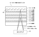
- FIG. 3 is a cross-sectional view showing the configuration of the optical disc 111 with a guide layer.
- the optical disc 111 with a guide layer has a guide layer 112 and a plurality of recording layers 113.
- An intermediate layer 114 having optical transparency is interposed between the guide layer 112 and the recording layer 113 closest thereto and between the adjacent recording layers 113.
- These layers are the protective layer 115, the recording layer 113, the intermediate layer 114, the recording layer 113, the intermediate layer 114, the recording layer 113, the intermediate layer 114, the recording layer 113, the intermediate layer from the side on which the recording / reproducing light R1 and the guide light R2 from the optical pickup 32 are incident.
- the layer 114, the recording layer 113, the intermediate layer 114, and the guide layer 112 are stacked in this order.
- a guide track 121 having a land / groove structure for tracking control is provided spirally or concentrically on the surface of the guide layer 112 facing the recording layer 113.
- On the side wall surface of the guide track 121 physical address information indicating track position information over the entire circumference of the disk is formed by modulation by wobble.
- the guide track 121 is formed with a track pitch (0.64 ⁇ m) corresponding to, for example, red laser light used for recording / reproduction of a DVD (Digital Versatile Disk).
- the average pitch between the land and the groove is 0.32 ⁇ m.
- the laser beam of the red laser beam is referred to as “guide light”. *
- tracking control by, for example, a differential push-pull method (DPP) is performed in each of the land and groove of the guide track 121.
- DPP differential push-pull method
- the recording layer 113 is a layer on which information is recorded at a track pitch (0.32 ⁇ m) corresponding to blue laser light used for recording / reproducing of a Blu-ray Disc (registered trademark), for example.
- this blue laser light is referred to as “recording / reproducing light” or “recording light”.
- the recording layer 113 is composed of, for example, a light absorption layer and a reflection layer.
- the light absorption layer organic dyes such as cyanine dyes and azo dyes, and inorganic materials such as Si, Cu, Sb, Te, and Ge are used.
- the target recording layer 113 in the optical disc 111 with the guide layer is irradiated with the recording light
- the reflectance of the region irradiated with the recording light changes, and the region with the changed reflectance is formed as a pit.
- Information is recorded on the recording layer 113.
- the recording layer 113 has a land / groove structure.
- the guide track 121 is not necessary. Therefore, the surface of the recording layer 113 may be flat.
- the optical disk 11 as a double-sided disk is configured by bonding and integrating two optical disks 111 with a guide layer so that the opposite surfaces of the land / groove structure surface of the guide layer 112 face each other.
- FIG. 4 is a diagram showing a configuration of regions divided by the radial positions of the guide layer 112 and the recording layer 113 in the optical disc 111 with a guide layer.
- the guide layer 112 and the recording layer 113 are divided into the lead-in area, the data area, and the lead-out area in common from the inner circumference side depending on the position in the radial direction. *
- management information unique to the optical disc 111 with the guide layer is recorded in advance by wobble modulation or the like.
- the management information specific to the optical disc 111 with guide layer identifies whether the optical disc 111 with guide layer constitutes a single-sided disc or a double-sided disc, and constitutes a double-sided disc. If the optical disc 111 is a disc, it includes surface management information for identifying which side of the front / back (side A / side B) of the double-sided disc the guide layer-attached optical disc 111 is.
- the surface management information included in the management information of the double-sided disc is also called “side surface identification information” in the sense that it is for identifying the side surface.
- the surface management information included in the single-sided disk management information is also referred to as “single-sided disk identification information” because it is for identifying a single-sided disk.
- the management information unique to the optical disc 111 with the guide layer includes, in addition to the surface management information described above, the number of recording layers, the recording method, the recording linear velocity, the laser power at the time of recording and reproduction, and the laser drive pulse waveform, etc.
- the recommended information, the position information of the data area, and the like may be included.
- a physical address assigned to the data area is recorded in advance by wobble modulation of the groove of the guide track 121 or the like.
- the same information as the information recorded in the lead-in area may be recorded in advance by wobble modulation or the like.
- the lead-in area of the recording layer 113 is an area where management information used for recording / reproducing on the recording layer 113 is recorded by a pit string.
- the management information used for recording / reproduction on the recording layer 113 includes recording of layer information such as a layer number assigned to the recording layer 113, replacement management information regarding replacement processing of a defective area, and optimum laser power during recording / reproduction. Includes playback conditions.
- the recording / playback conditions are determined by the disk drive 31 performing test recording on a part of the lead-in area (OPC area) and evaluating the result. *
- the disk transport mechanism 20 takes out the target optical disk 11 from the storage unit 10 and loads it into the disk drive 31 in the drive unit 30, or conversely, loads the optical disk 11 ejected from the disk drive 31 into the storage unit 10. It is a mechanism to return to. *
- the disk transport mechanism 20 can take out a plurality of optical disks 11 from the storage unit 10 at the same time and separately load them into a plurality of disk drives 31 in the drive unit 30. It is desirable to have a mechanism. *
- a plurality of disk drives 31 are mounted in the drive unit 30. In the example of FIG. 5, five disk drives 31 are mounted. The number of optical disks 11 accommodated in the storage unit 10 and the number of disk drives 31 mounted in the drive unit 30 are not necessarily the same. *
- FIG. 5 is a diagram showing a configuration of the disk drive 31 that is an optical recording apparatus.
- the disk drive 31 includes an optical pickup 32.
- the optical pickup 32 includes a recording / reproducing optical system corresponding to the recording / reproducing light and a guide optical system corresponding to the guide light.
- the recording / reproducing optical system includes a first light source 33, a first collimator lens 34, a first polarizing beam splitter 35, a first relay lens 36, a second collimator lens 37, a combining prism 38, and a quarter wavelength plate. 39, an objective lens 60, a first light receiving lens 61, a first light receiving portion 62, and the like.
- the combining prism 38, the quarter wavelength plate 39, and the objective lens 60 belong to both the recording / reproducing optical system and a guide optical system described later.
- the first light source 33 includes a laser diode that emits laser light having a first wavelength as recording / reproducing light R1.
- the recording / reproducing light R 1 emitted from the first light source 33 is converted into parallel light by the first collimator lens 34, and passes through the first polarization beam splitter 35, the first relay lens 36 and the second collimator lens 37.
- the light enters the combining prism 38.
- the synthesizing prism 38 receives recording / reproducing light R1 incident from the second collimator lens 37 and guide light R2 having a second wavelength incident from a third collimator lens belonging to a guide optical system described later. These are combined so that the axes coincide with each other, and enter the objective lens 60 through the quarter-wave plate 39.
- the incident recording / reproducing light is collected by the objective lens 60 so as to be focused on the target recording layer 113 (FIG. 3) of one optical disc 111 with a guide layer of the optical disc 11 which is a double-sided disc. *
- the recording / reproducing light (returned light) reflected by the recording layer 113 is incident on the combining prism 38 via the objective lens 60 and the quarter wavelength plate 39, and is transmitted through the combining prism 38 in the incident direction.
- the first polarization beam splitter 35 reflects the return light of the first wavelength from the first relay lens 36 at an angle of about 90 degrees and passes through the first light receiving lens 61 to the first light receiving unit 62. Make it incident.
- the first light receiving unit 62 includes, for example, a light receiving element whose light receiving surface is divided into a total of four in length and breadth, and outputs a voltage signal having a level corresponding to the received light intensity of each divided light receiving surface as a reproduction signal.
- the guide optical system (first guide optical system, second guide optical system) includes a second light source 63, a third collimator lens 64, a second polarization beam splitter 65, a second relay lens 66, and a fourth.
- the second light source 63 emits guide light R2 that is red laser light.
- the guide light R2 emitted from the second light source 63 is converted into parallel light by the third collimator lens 64, and is combined through the second polarization beam splitter 65, the second relay lens 66, and the fourth collimator lens 67.
- the light enters the prism 38.
- the guide light R2 incident on the combining prism 38 has the optical axis of the recording / reproducing light R1 having the first wavelength incident on the combining prism 38 from the second collimator lens 37 of the recording / reproducing optical system. They are synthesized so as to coincide with each other and enter the objective lens 60 through the quarter-wave plate 39.
- the incident guide light R2 is collected by the objective lens 60 so as to be focused on the guide layer 112 (FIG. 3) of the optical disc 111 with one guide layer of the optical disc 11 which is a double-sided disc. *
- the guide light R2 (return light) reflected by the guide layer 112 enters the synthesis prism 38 through the objective lens 60 and the quarter wavelength plate 39, and is reflected by the synthesis prism 38 at an angle of about 90 degrees.
- the second polarization beam splitter 65 reflects the return light of the guide light R2 from the second relay lens 66 at an angle of about 90 degrees, and passes through the second light receiving lens 68 to the second light receiving unit 69. Make it incident. *
- the second light receiving unit 69 includes, for example, a light receiving element in which the light receiving surface is divided into a total of four in length and width, and outputs a voltage signal having a level corresponding to the light reception intensity for each of the divided light receiving surfaces as a reproduction signal.
- the optical pickup 32 is provided with a tracking actuator 70 and a focusing actuator (not shown).
- the tracking actuator 70 moves the objective lens 60 in the disk radial direction that is perpendicular to the optical axis under the control of the tracking control unit 71.
- the focusing actuator moves the objective lens 60 in the optical axis direction under the control of a focus control unit (not shown). *
- the optical pickup 32 includes a first relay lens actuator that moves the first relay lens 36 in the optical axis direction so as to switch the recording layer 113 irradiated with the recording / reproducing light, and a first relay lens actuator.
- a second relay lens actuator for moving the second relay lens 66 in the optical axis direction is provided. The above is the description of the optical pickup 32. *
- the disk drive 31 includes a data modulating unit 72, a first light source driving unit 73, a second light source driving unit 74, an equalizer 75, a data reproducing unit 76, a tracking error generating unit 77, It includes a tracking control unit 71, a management information reproducing unit 78, a disk motor driving unit 79, a feed mechanism 80, a controller 81, a focus control unit (not shown), a relay lens control unit, and the like.
- the data modulation unit 72 modulates the recording data supplied from the controller 81 and supplies the modulation signal to the first light source driving unit 73.
- the first light source drive unit 73 generates a drive pulse for driving the first light source 33 based on the modulation signal from the data modulation unit 72.
- the equalizer 75 performs an equalization process such as PRML (Partial Response Maximum Likelihood) on the reproduction RF signal from the first light receiving unit 62 to generate a binary signal.
- PRML Partial Response Maximum Likelihood
- the data reproduction unit 76 demodulates data from the binary signal output from the equalizer 75, performs decoding processing such as error correction from the demodulated data, generates reproduction data, and supplies the reproduction data to the controller 81.
- the tracking error generation unit 77 generates a tracking error signal based on the output of the second light receiving unit 69 by, for example, a differential push-pull method and supplies the tracking error signal to the tracking control unit 71.
- the tracking control unit 71 controls the tracking actuator 70 based on the tracking error signal from the tracking error generation unit 77 to move the objective lens 60 in a direction perpendicular to the optical axis to perform tracking control.
- the management information reproducing unit 78 reproduces, for example, management information modulated into wobble and supplies it to the controller 81.
- the disk motor drive unit 79 supplies a drive signal to a disk motor 82 that rotates the optical disk 11 under the control of the controller 81.
- the feed mechanism 80 is a mechanism for transporting the optical pickup 32 in the radial direction of the optical disc 11. *
- a focus control unit moves the objective lens 60 in the optical axis direction by driving a focusing actuator (not shown).
- the controller 81 (control unit) includes a CPU (Central Processing Unit), a ROM (Read Only Memory), a RAM (Random Access Memory), and the like.
- the controller 81 controls the entire disk drive 31 based on a program loaded in the main memory area allocated to the RAM. *
- a plurality of the disk drives 31 described above are mounted on the drive unit 30 and can be controlled independently, and information can be recorded and reproduced on the loaded optical disk 11 simultaneously.
- each disc drive 31 has one side (front side) and the other side (back side) of the optical disc 11.
- the optical pickups 32 are arranged one by one as a first optical pickup (including a first guide light optical system) and a second optical pickup (including a second guide light optical system), respectively.
- a data modulation unit 72 a first light source drive unit 73, a second light source drive unit 74, an equalizer 75, a data reproduction unit 76, a tracking error generation unit 77, a tracking control unit 71, A management information reproduction unit 78, a feed mechanism 80, a focus control unit, a relay lens control unit, and the like are provided.
- the controller 81 collectively performs the control of the two systems.
- RAID Controller 40 A RAID (Redundant Arrays of Inexpensive Disks) controller 40 records data in multiple on one or more disk drives 31 in the drive unit 30 in response to a recording command from the host device 50, or performs striping. RAID control to record in a distributed manner is performed. *
- the controller 81 of each disk drive 31 to which a recording or reproduction instruction is given from the RAID controller 40 performs control for recording or reproducing data with respect to the optical disk 111 with guide layers on both sides of the optical disk 11. .
- the host device 50 is the highest-level device that controls the optical recording system 1.
- the host device 50 may be a personal computer.
- the host device 50 creates or prepares data for recording, and supplies a recording command for the data for recording to the RAID controller 40. Further, the host device 50 supplies a read command including a file name designated by a user or the like to the RAID controller 40, and acquires data of the corresponding file name from the RAID controller 40 as a response.
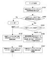
- FIG. 6 is a flowchart showing a control procedure based on the surface management information by the disk drive 31. *
- the controller 81 moves the optical pickups 32 on both sides to a position where the lead-in area of the optical disk 11 can be read to read the guide layers 112 on both sides.
- An attempt is made to read the surface management information from the in area (step S101). *
- the side of the double-sided disk is obtained from the signal read from the lead-in area of the guide layer 112 of the corresponding optical disc 111 with the guide layer by the optical pickups 32 on both sides.
- Management information including surface management information (side surface identification information) for identifying a surface (A surface / B surface) is reproduced by the management information reproducing unit 78 (Yes in step S102, double-sided disk in step S103).
- the controller 81 Based on the surface management information reproduced by the management information reproducing unit 78, the controller 81 reads one optical pickup 32 that has read the surface management information indicating the table (A surface) as the side surface of the double-sided disk, and displays the surface of the double-sided disk.
- the other optical pickup 32 that has read the surface management information indicating the back side (B side) as the side surface of the double-sided disc is assigned to the processing on the back side (B side) of the double-sided disc (side A).
- Step 104 The correlation between the side surfaces of the double-sided disk and the two optical pickups 32 is held in the controller 81 until the optical disk 11 is ejected from the disk drive 31. *
- controller 81 performs control so as to continue reading the lead-in areas of the guide layer 112 and the target recording layer 113 on both sides of the double-sided disk using the optical pickups 32 on both sides (step S105).
- step S102 the management information is read from the lead-in area of the guide layer 12 by one of the two optical pickups 32 and reproduced by the management information reproducing unit 78 (Yes in step S102).
- the surface management information obtained from the lead-in area of the guide layer 112 of the single-sided disc is single-sided disc identification information (single-sided disc in step S103).
- the controller 81 determines that the surface management information included in the management information reproduced by the management information reproducing unit 78 is single-sided disk identification information
- the controller 81 reads one of the optical pickups 32 that has read the management information including the surface management information.
- the operation of the other optical pickup 32 is stopped (step S106). Note that to stop the operation of the optical pickup 32 means, for example, stopping emission of guide light and recording / reproducing light from the optical pickup 32 and retracting to a predetermined standby position. Note that a single-sided disk is treated as the A-side of a double-sided disk, for example. *
- controller 81 performs control so as to continue reading the lead-in areas of the guide layer 112 and the recording layer 113 of the single-sided disk using one optical pickup 32 corresponding to the single-sided disk (step S107).
- the surface management information for identifying the side surfaces of the double-sided disc is recorded on the guide layer 112, whereby the surface management information is recorded on the recording layer 113 by prepits or the like.
- the surface management information is recorded on the recording layer 113 by prepits or the like.
- an optical disc having at least one recording layer that causes an error in reading the surface management information must be disposed of as a defective product. Therefore, the probability of occurrence of defective products tends to increase as the number of recording layers stacked, but if the surface management information is recorded in the guide layer 112, such a tendency can be eliminated.
- the controller 81 is the surface read from the lead-in area of the guide layer 12 by one of the processing systems of the two optical pickups 32. It is determined based on the management information that a single-sided disc has been loaded. This makes it possible to determine a single-sided disk more quickly and reliably compared to a method for judging that it is a single-sided disk by determining errors such as tracking pull-in failure. In addition, it is possible to shorten the time until recording of user data on the single-sided disk is started. *
- surface management information (A surface / B surface) is used as index information when archiving data (files) recorded on the recording layer 113 of the optical disk 11 (created as a batch file). ) Can be used.
- the plane management information (A plane / B plane) as the data (file) search condition, the search efficiency can be improved.
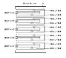
- FIG. 7 shows a state in which the optical disk 11, which is a double-sided disk, is set in each disk drive 31 of the drive unit 30 with the front and back sides (A / B side) aligned.
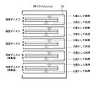
- This state is most typical, but is not essential in the optical recording system 1 of the present embodiment. That is, every time a double-sided disk is loaded, the controller 81 of the disk drive 31 sets the optical pickup 32 that has read the surface management information indicating the surface (surface A) as a processing system corresponding to the surface (surface A). This is because the processing system including the optical pickup 32 that has read the surface management information indicating the back surface (B surface) is set as the processing system corresponding to the back surface (B surface). Therefore, in the optical recording system 1 of the present embodiment, for example, as shown in FIG. 8, restrictions on the front and back directions when the optical disk 11 that is a double-sided disk is set in the drive unit 30 can be eliminated.
- FIG. 8 shows a state in which the optical disk 11, which is a double-sided disk is set in the
- the side surface (A side / B side) of the double-sided disc is identified from the signal read from the lead-in area of the guide layer 112 of the corresponding optical disc 111 with the guide layer by the optical pickup 32.
- Management information including the side management information (side surface identification information) is reproduced by the management information reproduction unit 78. Therefore, in this case, the controller 81 assigns the optical pickup 32 and the side surface of the double-sided disk based on the surface management information reproduced by the management information reproducing unit 78. That is, when the reproduced surface management information is side identification information indicating the table (A surface), the controller 81 assigns the optical pickup 32 to the processing on the surface (A surface) side of the double-sided disc. On the contrary, when the reproduced surface management information is side identification information indicating the back side (B side), the controller 81 assigns the optical pickup 32 to the processing on the back side (B side) of the double-sided disc.
- the optical pickup 32 identifies the single-sided disc from the signal read from the lead-in area of the guide layer 112 of the optical disc 111 with the guide layer constituting the single-sided disc as a single unit.
- the management information including the surface management information is reproduced by the management information reproducing unit 78. Therefore, in this case, the controller 81 assigns the optical pickup 32 to the processing of the single-sided disk as it is based on the surface management information reproduced by the management information reproducing unit 78.
- the controller 81 determines an error as a state where the single-sided disk is set upside down because the optical pickup 32 fails to detect the disk itself.
- the controller 81 determines this error, for example, the host device 50 notifies the host device 50 of the error, and the host device 50 performs processing such as notifying the user of an error in the orientation of the front and back of the optical disk 11 according to the notification.
- the disc transport mechanism 20 has a function capable of reversing the orientation of the front and back of the optical disc 11, the disc transport mechanism 20 is instructed to reverse the optical disc 11.
- the surface management information is recorded by wobble modulation in the lead-in area of the guide layer.
- the surface management information is recorded by pre-pits in the lead-in area of the guide layer. May be.
Landscapes
- Optical Recording Or Reproduction (AREA)
- Optical Head (AREA)
Description
本発明は、ガイド層と複数の記録層を有するガイド層付き光記録媒体、このガイド層付き光記録媒体に対しての記録を行う多層光記録媒体および光記録装置に関する。
DVD(Digital Versatile Disk)、ブルーレイディスク(登録商標)などの光ディスクの大容量化を目的として、記録層を多層化することが行われる。記録層の多層化に伴い、記録層へのデータの記録または再生時のトラックキング制御を、記録層とは別の層に設けられたガイドトラックを用いて行う方式も知られている。例えば、溝構造によるガイドトラックが設けられたガイドトラック層に390nm~420nmの波長(青色)の光を使用してトラッキング制御を行うとともに、複数の記録層の中の一つの記録層に650nm~680nmの波長(赤色)の光を使用して記録を行う光ドライブ装置などがある(例えば、特許文献1等)。
さらには、データ転送速度を向上させるため、光ディスクに設けられた複数の記録層に対して複数の光ピックアップにより同時にデータを記録したり読み出したりする方式も知られている。例えば、ディスクの表側の記録層と裏側の記録層に対し、2つの光ピックアップを使って同時にCLV(Constant Linear Velocity)方式で記録再生を行う装置などが知られている。(例えば、特許文献2等)。
また、両面に対して記録再生を行うことが可能な光ディスクにおいて、それぞれの記録面のリードイン領域にA/B面の識別情報をプリピットにより記録したものもある。A/B面の識別情報により、ドライブ装置にA/B面の向きが誤って挿入された場合に、ドライブ装置側で記録媒体の誤挿入を認識することが可能とされている(例えば、特許文献3等)。
複数の記録層を両面側にそれぞれ有する両面ディスクに対して2つの光ピックアップを用いて両面側から同時に記録を行うことが可能な光記録装置を想定した場合、当該光ディスクそれぞれの面と2つの光ピックアップとの相関を光記録装置に設定するために、光ディスクの両面の記録層にそれぞれの面を識別するための面情報を記録しておく必要がある。この際、両面の複数の記録層のすべてに面情報をプリピットなどによって記録しておかなければならない。しかし、記録層に面情報をはじめとする管理情報をプリピットなどにより記録することは、記録層の積層数が増加するにつれて、管理情報の読み込み不能による不良品の発生確率の増大を招く。このことが記録媒体製品の価格をつり上げる要因の一つとして数えられていた。
また、両面ディスクと片面のみに記録層を有する片面ディスクに光記録装置を対応させるためには、トラッキングの引き込み失敗などのエラーの判定を含む片面ディスクの判定アルゴリズムなどを光記録装置に実装する必要がある。しかし、片面ディスクの判定アルゴリズムではトラッキングの引き込みのリトライなど、繰り返し処理を伴うため判定に時間がかかり、応答性の低下を招く要因となる。
以上のような事情に鑑み、本発明の目的は、管理情報の読み込み不能による製造歩留りの低下を抑制できるとともに、両面ディスクと片面ディスクの判別処理の迅速化を図ることのできる多層光記録媒体および光記録装置を提供することにある。
上記目的を達成するため、本発明の一形態に係る多層光記録媒体は、情報を記録可能な複数の記録層と、トラッキングのためのガイドトラックが設けられ、当該ガイドトラックに沿って管理情報が予め記録されたリードイン領域を有するガイド層とを有する2つのガイド層付き光記録媒体が、それぞれ両面に記録が可能な両面ディスクを構成するように互いに貼り合わせて一体化され、前記管理情報が前記両面ディスクのサイド面を識別するためのサイド面識別情報を含む。
本発明に係る多層光記録媒体は、ガイド層のリードイン領域に、両面ディスクのサイド面を識別するためのサイド面識別情報を含む管理情報を予め記録したことにより、記録層に面管理情報をプリピットなどにより記録しておく場合に比較して、面情報の読み込み不能による不良品の発生確率を低下させることができ、製造歩留りの向上を図ることができる。
本発明の別の形態に係る光記録装置は、情報を記録可能な複数の記録層と、トラッキングのためのガイドトラックが設けられ、当該ガイドトラックに沿って管理情報が予め記録されたリードイン領域を有するガイド層とを有する2つのガイド層付き光記録媒体が、それぞれ両面に記録が可能な両面ディスクを構成するように互いに貼り合わせて一体化され、前記管理情報が前記両面ディスクのサイド面を識別するためのサイド面識別情報を含む多層光記録媒体に記録可能な光記録装置であって、前記多層光記録媒体の一方の前記ガイド層付き光記録媒体に対応して設けられ、当該一方のガイド層付き光記録媒体の前記ガイド層に第1のガイド光を集光し、その反射光を受光する第1のガイド光学系を有する第1の光ピックアップと、前記多層光記録媒体の他方の前記ガイド層付き光記録媒体に対応して設けられ、当該他方のガイド層付き光記録媒体の前記ガイド層に第2のガイド光を集光し、その反射光を受光する第2のガイド光学系を有する第2の光ピックアップと、前記第1のガイド光学系にて受光された前記第1のガイド光をもとに前記一方のガイド層付き多層記録媒の前記ガイド層に記録された前記管理情報を第1の管理情報として再生するとともに、前記第2のガイド光学系にて受光された前記第2のガイド光をもとに前記他方のガイド層付き多層記録媒の前記ガイド層に記録された前記管理情報を第2の管理情報として再生する管理情報再生部と、再生された前記第1の管理情報および前記第2の管理情報にそれぞれ含まれる前記サイド面識別情報をもとに前記第1の光ピックアップおよび前記第2の光ピックアップと前記両面ディスクのサイド面との相関を設定する制御部とを具備する。
本発明に係る光記録装置によれば、両面ディスクの両側のガイド層付き光記録媒体それぞれのガイド層のリードイン領域から、両面ディスクのサイド面を識別するためのサイド面識別情報をそれぞれ含む第1の管理情報および第2の管理情報を読み込むことができる。また、制御部は、第1の管理情報および第2の管理情報にそれぞれ含まれるサイド面識別情報をもとに第1の光ピックアップおよび第2の光ピックアップと両面ディスクのサイド面との相関を設定することによって、光記録装置に両面ディスクがセットされる際の表裏の向きの制約がない。
本発明に係る光記録装置であって、前記多層光記録媒体を第1の多層光記録媒体、前記ガイド層付き光記録媒体が片面に記録が可能な片面ディスクとして単体で使用され、前記管理情報に前記片面ディスクであることを識別するための片面ディスク識別情報が含まれる多層光記録媒体を第2の多層光記録媒体として択一的にセット可能とされ、前記第2の多層光記録媒体がセットされたとき、前記面管理情報再生部は、前記第1の光ピックアップおよび前記第2の光ピックアップのうち一方の光ピックアップにて受光されたガイド光をもとに前記管理情報を再生し、前記制御部は、再生された前記管理情報に含まれる前記片面ディスク識別情報をもとに、前記第1の光ピックアップおよび前記第2の光ピックアップのうち他方の光ピックアップの動作を停止状態にするものであってよい。
これにより、トラッキングの引き込み失敗などのエラーの判定により片面ディスクであることを判定する方式に比較して、より迅速かつ確実に片面ディスクの判定を行うことができ、片面ディスクが装填されてから実際にその片面ディスクへのユーザデータの記録が開始されるまでの時間を短縮することができる。
以上のように、本発明によれば、管理情報の読み込み不能による製造歩留りの低下を抑制できるとともに、両面ディスクと片面ディスクの判別処理の迅速化を図ることができる。
以下、図面を参照しながら、本発明の実施形態を説明する。 図1は、本発明の一実施形態に係る光記録システムを示す図である。
図1は光記録システムの全体の構成を示す図である。 この光記録システム1は、ストレージユニット10と、ディスク搬送機構20と、ドライブユニット30と、RAIDコントローラ40と、ホスト装置50とを備える。以下、それぞれの詳細について説明する。
[ストレージユニット10] ストレージユニット10は、複数の多層光記録媒体である光ディスク11が個別に着脱自在に収容されるユニットである。
ストレージユニット10内での複数の光ディスク11の収容形態としては平積み、縦並びなどが想定される。いずれの場合も、ストレージユニット10に対して光ディスク11の出し入れが円滑に行われるように、隣り合う光ディスク11間には一定の隙間が設けられることが好ましい。ストレージユニット10の形状は、ユーザによるハンドリング性、光ディスク11の収納効率などの点から、例えば直方体形状、円筒形状などが想定される。図1の例では、複数の光ディスク11を平積みで収容した直方体形状のストレージユニット10が用いられる。
図2は、ストレージユニット10、光ディスク11およびドライブユニット30の構成を示す図である。 ストレージユニット10の少なくとも一つの側面には光ディスク11の出し入れのための開口部101と、この開口部101を開閉する扉(図示せず)とが設けられている。扉はディスク搬送機構20によるストレージユニット10からの光ディスク11の出し入れの動作と連動して開閉され、その他のときは閉状態とされる。
なお、本発明において、ストレージユニット10の構成は図2のものに限定されない。ストレージユニット10の形状、開口部の数や位置、扉の有無、複数の光ディスク11の収容形態など、様々な変形が可能である。
[光ディスク11] ストレージユニット10に収容される光ディスク11は、ガイド層と記録層とが別々の層に分離して形成された、いわゆる「ガイド層付き光ディスク」である。特にこの実施形態では、2枚のガイド層付き光ディスクを貼り合わせた両面記録型の光ディスクと、ガイド層付き光ディスクを単体で使用した片面記録型の光ディスクが用いられる。以降、両面記録型の光ディスクを「両面ディスク」、片面記録型の光ディスクを「片面ディスク」とそれぞれ略称する。
図3はガイド層付き光ディスク111の構成を示す断面図である。 ガイド層付き光ディスク111は、ガイド層112と複数の記録層113とを有する。同図のガイド層付き光ディスク1
11の例では記録層113の層数は"4"である。ガイド層112とこれに最も近い記録層113との間、隣り合う記録層113の間との間には光透過性を有する中間層114がそれぞれ介層されている。これらの層は、光ピックアップ32からの記録再生光R1およびガイド光R2が入射される側から、保護層115、記録層113、中間層114、記録層113、中間層114、記録層113、中間層114、記録層113、中間層114、ガイド層112の順に積層配置される。
11の例では記録層113の層数は"4"である。ガイド層112とこれに最も近い記録層113との間、隣り合う記録層113の間との間には光透過性を有する中間層114がそれぞれ介層されている。これらの層は、光ピックアップ32からの記録再生光R1およびガイド光R2が入射される側から、保護層115、記録層113、中間層114、記録層113、中間層114、記録層113、中間層114、記録層113、中間層114、ガイド層112の順に積層配置される。
ガイド層112において記録層113に対向する側の面には、トラッキング制御のためのランド・グルーブ構造によるガイドトラック121がスパイラル状あるいは同心円状に設けられている。ガイドトラック121の側壁面にはウォブルによる変調によって、ディスク全周のわたるトラック位置情報を示す物理アドレス情報が形成されている。ガイドトラック121は、例えばDVD(Digital Versatile Disk)の記録再生に用いられる赤色レーザ光に対応するトラックピッチ(0.64μm)で形成される。ランドとグルーブ間のピッチの平均は0.32μmである。以後、赤色レーザ光のレーザ光を「ガイド光」と呼ぶ。
本実施形態の光記録システム1では、ガイドトラック121のランドとグルーブのそれぞれにおいて、例えば、差動プッシュプル法(DPP:Differential Push-Pull)などによるトラッキング制御が行われる。ガイドトラック121のランドとグルーブのそれぞれにおいてトラッキング制御が行われることで、記録層113に対する情報の記録は0.32μmのトラックピッチで行うことが可能である。
記録層113は、例えばブルーレイディスク(登録商標)の記録再生に用いられる青色レーザ光に対応するトラックピッチ(0.32μm)で情報の記録が行われる層である。以後、この青色レーザ光を「記録再生光」または「記録光」と呼ぶ。記録層113は、例えば光吸収層と反射層等とにより構成される。光吸収層としてはシアニン系色素やアゾ系色素等の有機色素や、Si、Cu、Sb、Te、Ge等の無機材料が用いられる。記録光がガイド層付き光ディスク111における目的の記録層113に照射されると、その記録光が照射された領域の反射率が変化し、反射率が変化した領域がピットとして形成されることで、記録層113に情報が記録される。
なお、記録層113への情報の記録時および再生時のトラッキング制御および物理アドレスならびに基準クロックの取得は、ガイド層112のガイドトラック121を用いて行われるため、記録層113にはランド・グルーブ構造によるガイドトラック121は不要である。したがって、記録層113の表面は平坦でよい。
両面ディスクとしての光ディスク11は、2枚のガイド層付き光ディスク111がガイド層112のランド・グルーブ構造面の逆側の面どうしを対向させるようにして貼り合わせて一体化することにより構成される。
図4はガイド層付き光ディスク111におけるガイド層112および記録層113の半径方向の位置によって区分される領域の構成を示す図である。 ガイド層112および記録層113は、半径方向における位置によって内周側よりリードイン領域、データ領域、リードアウト領域に各層共通に区分される。
ガイド層112のリードイン領域には、ガイド層付き光ディスク111に固有の管理情報がウォブル変調などによって予め記録されている。 ガイド層付き光ディスク111に固有の管理情報は、当該ガイド層付き光ディスク111が片面ディスクを単体で構成するものであるか、両面ディスクを構成するものであるかを識別するとともに、両面ディスクを構成するものである場合には当該ガイド層付き光ディスク111が両面ディスクの表/裏(A面/B面)のどちらのサイド面であるかを識別するための面管理情報を含む。 両面ディスクの管理情報に含まれる面管理情報はサイド面を識別するためのものであるという意味から「サイド面識別情報」とも呼ばれる。 また、片面ディスクの管理情報に含まれる面管理情報は、片面ディスクであることを識別するためのものであるという意味から「片面ディスク識別情報」とも呼ばれる。
ガイド層付き光ディスク111に固有の管理情報は、上記の面管理情報のほか、ガイド層付き光ディスク111の記録層の数、記録方式、記録線速度、記録再生時のレーザパワーおよびレーザ駆動パルス波形などの推奨情報、データ領域の位置情報などを含むものであってよい。
ガイド層112のデータ領域には、当該データ領域に対して割り当てられる物理アドレスなどが、ガイドトラック121のグルーブのウォブル変調などによって予め記録されている。 なお、ガイド層112のリードアウト領域にも、リードイン領域に記録された情報と同一の情報がウォブル変調などによって予め記録されていてもよい。
記録層113のリードイン領域は、記録層113への記録再生に用いられる管理情報がピット列によって記録される領域である。記録層113への記録再生に用いられる管理情報は、当該記録層113に割り当てられた層番号などの層情報、欠陥領域の交替処理に関する交替管理情報、記録再生時の最適なレーザパワーなどの記録再生条件などを含む。記録再生条件は、リードイン領域内の一部の領域(OPC領域)に対してディスクドライブ31がテスト記録を行い、その結果を評価することによって決定される。
[ディスク搬送機構20] ディスク搬送機構20は、ストレージユニット10から目的の光ディスク11を取り出してドライブユニット30内のディスクドライブ31に装填したり、逆にディスクドライブ31から排出された光ディスク11をストレージユニット10に戻したりするための機構である。
ディスク搬送機構20は、例えば、ストレージユニット10から同時に複数の光ディスク11を取り出して、ドライブユニット30内の複数のディスクドライブ31に別々に装填することができるように、独立して動作可能な複数の搬送機構を備えたものであることが望ましい。
[ドライブユニット30] ドライブユニット30には複数のディスクドライブ31が搭載される。同図の例では、5機のディスクドライブ31が搭載される。ストレージユニット10に収容される光ディスク11の数とドライブユニット30内に搭載されるディスクドライブ31の数は必ずしも同じとする必要はない。
(ディスクドライブ31の構成) 図5は光記録装置であるディスクドライブ31の構成を示す図である。 このディスクドライブ31は、光ピックアップ32を備える。光ピックアップ32は、記録再生光に対応する記録再生光学系と、ガイド光に対応するガイド光学系とを備える。
記録再生光学系は、第1の光源33、第1のコリメータレンズ34、第1の偏光ビームスプリッタ35、第1のリレーレンズ36、第2のコリメータレンズ37、合成プリズム38、1/4波長板39、対物レンズ60、第1の受光レンズ61および第1の受光部62などで構成される。ここで、合成プリズム38、1/4波長板39、対物レンズ60は、当該記録再生光学系と後述するガイド光学系の両方に属する。
第1の光源33は第1の波長のレーザ光を記録再生光R1として出射するレーザダイオードを備える。第1の光源33から出射された記録再生光R1は第1のコリメータレンズ34によって平行光とされ、第1の偏光ビームスプリッタ35、第1のリレーレンズ36及び第2のコリメータレンズ37を介して合成プリズム38に入射する。合成プリズム38は、第2のコリメータレンズ37から入射される記録再生光R1と、後述するガイド光学系に属する第3のコリメータレンズから入射される第2の波長のガイド光R2とを互いの光軸が一致するように合成し、1/4波長板39を介して対物レンズ60に入射させる。対物レンズ60にて、入射された記録再生光は、両面ディスクである光ディスク11の一方のガイド層付き光ディスク111の目的の記録層113(図3)に合焦させるように集光される。
記録層113によって反射された記録再生光(戻り光)は、対物レンズ60、1/4波長板39を介して合成プリズム38に入射し、合成プリズム38を入射方向のまま透過して、第2のコリメータレンズ37及び第1のリレーレンズ36を介して第1の偏光ビームスプリッタ35に戻る。第1の偏光ビームスプリッタ35は、第1のリレーレンズ36からの第1の波長の戻り光を約90度の角度で反射して第1の受光レンズ61を介して第1の受光部62に入射させる。
第1の受光部62は、例えば受光面が縦横に計4分割された受光素子を有し、分割された受光面毎の受光強度に応じたレベルの電圧信号を再生信号として出力する。
ガイド光学系(第1のガイド光学系、第2のガイド光学系)は、第2の光源63、第3のコリメータレンズ64、第2の偏光ビームスプリッタ65、第2のリレーレンズ66、第4のコリメータレンズ67、合成プリズム38、1/4波長板39、対物レンズ60、第2の受光レンズ68および第2の受光部69などで構成される。
第2の光源63は、赤色レーザ光であるガイド光R2を出射する。第2の光源63から出射されたガイド光R2は第3のコリメータレンズ64によって平行光とされ、第2の偏光ビームスプリッタ65、第2のリレーレンズ66及び第4のコリメータレンズ67を介して合成プリズム38に入射する。合成プリズム38に入射されたガイド光R2は、前述したように、合成プリズム38にて記録再生光学系の第2のコリメータレンズ37から入射される第1の波長の記録再生光R1と光軸が一致するように合成され、1/4波長板39を介して対物レンズ60に入射される。対物レンズ60にて、入射されたガイド光R2は、両面ディスクである光ディスク11の一方のガイド層付き光ディスク111のガイド層112(図3)に合焦させるように集光される。
ガイド層112によって反射されたガイド光R2(戻り光)は、対物レンズ60、1/4波長板39を介して合成プリズム38に入射し、合成プリズム38にて約90度の角度で反射され、第4のコリメータレンズ67及び第2のリレーレンズ66を介して第2の偏光ビームスプリッタ65に戻る。第2の偏光ビームスプリッタ65は、第2のリレーレンズ66からのガイド光R2の戻り光を、約90度の角度で反射して第2の受光レンズ68を介して第2の受光部69に入射させる。
第2の受光部69は、例えば受光面が縦横に計4分割された受光素子を有し、分割された受光面毎の受光強度に応じたレベルの電圧信号を再生信号として出力する。
また、光ピックアップ32には、トラッキングアクチュエータ70とフォーカシングアクチュエータ(図示せず)が設けられている。トラッキングアクチュエータ70はトラッキング制御部71による制御のもとで対物レンズ60を光軸に対して垂直な方向であるディスク半径方向に移動させる。フォーカシングアクチュエータは、図示しないフォーカス制御部による制御のもと対物レンズ60を光軸方向に移動させる。
さらに、図示は省略したが、光ピックアップ32には、記録再生光が照射される記録層113を切り替えるように第1のリレーレンズ36を光軸方向に移動させる第1のリレーレンズアクチュエータと、第2のリレーレンズ66を光軸方向に移動させる第2のリレーレンズアクチュエータが設けられている。 以上が、光ピックアップ32の説明である。
ディスクドライブ31は、上記の光ピックアップ32のほか、データ変調部72、第1の光源駆動部73、第2の光源駆動部74、等化器75、データ再生部76、トラッキングエラー生成部77、トラッキング制御部71、管理情報再生部78、ディスクモータ駆動部79、フィード機構80、コントローラ81、さらには図示しないフォーカス制御部、リレーレ
ンズ制御部などを有する。
ンズ制御部などを有する。
データ変調部72は、コントローラ81より供給された記録用のデータを変調し、変調信号を第1の光源駆動部73に供給する。
第1の光源駆動部73は、データ変調部72からの変調信号をもとに第1の光源33を駆動するための駆動パルスを生成する。
等化器75は、第1の受光部62からの再生RF信号に対して、例えばPRML(Partial Response Maximum Likelihood)などの等化処理を行って二値信号を生成する。
データ再生部76は、等化器75より出力された二値信号からデータを復調し、復調されたデータから誤り訂正などの復号処理を行って再生データを生成し、コントローラ81に供給する。
トラッキングエラー生成部77は、第2の受光部69の出力をもとに、例えば差動プッシュプル法などによってトラッキングエラー信号を生成し、トラッキング制御部71に供給する。
トラッキング制御部71は、トラッキングエラー生成部77からのトラッキングエラー信号をもとにトラッキングアクチュエータ70を制御して対物レンズ60を光軸に対して垂直な方向に移動させてトラッキング制御を行う。
管理情報再生部78は、第2の受光部69の出力をもとに、例えばウォブルに変調された管理情報を再生してコントローラ81に供給する。
ディスクモータ駆動部79は、コントローラ81による制御のもと光ディスク11を回転駆動させるディスクモータ82に駆動信号を供給する。
フィード機構80は、光ピックアップ32を光ディスク11の半径方向に搬送する機構である。
図示しないフォーカス制御部は、図示しないフォーカシングアクチュエータを駆動させることにより、対物レンズ60を光軸方向に移動させる。
コントローラ81(制御部)は、CPU(Central Processing Unit)、ROM(Read Only Memory)、RAM(Random Access Memory)などを備える。コントローラ81は、RAMに割り当てられたメインメモリの領域にロードされたプログラムに基づいて、ディスクドライブ31の全体の制御を行う。
ドライブユニット30には、上記のディスクドライブ31が複数搭載され、それぞれ独立して制御可能とされ、装填された光ディスク11に対する情報の記録および再生をそれぞれ同時に行うことができる。
本実施形態の光記録システム1は、両面ディスクへの対応を想定しているため、それぞれのディスクドライブ31には、当該光ディスク11の一方の面(表面)と他方の面(裏面)のそれぞれに対応して光ピックアップ32が一機ずつ第1の光ピックアップ(第1のガイド光光学系を含む。)および第2の光ピックアップ(第2のガイド光光学系を含む。)として配置され、それぞれの光ピックアップ32に対応してデータ変調部72、第1の光源駆動部73、第2の光源駆動部74、等化器75、データ再生部76、トラッキングエラー生成部77、トラッキング制御部71、管理情報再生部78、フィード機構80、フォーカス制御部、リレーレンズ制御部などが設けられている。そしてコントローラ81は、上記2系統の制御を総括して行うものとされている。
[RAIDコントローラ40] RAID(Redundant Arrays of Inexpensive Disks)コントローラ40は、ホスト装置50からの記録命令などに対して、ドライブユニット30内の1以上のディスクドライブ31にデータを多重に記録したり、ストライピングにより分散して記録したりするRAID制御を行う。
RAIDコントローラ40より記録または再生の指示が与えられたそれぞれのディスクドライブ31のコントローラ81は、光ディスク11の両側のガイド層付き光ディスク111に対してデータを記録したり再生したりするための制御を行う。
[ホスト装置50] ホスト装置50は、本光記録システム1を制御する最上位の装置である。ホスト装置50はパーソナルコンピュータでもよい。ホスト装置50は、記録用のデータを作成または準備し、RAIDコントローラ40に対して当該記録用のデータの記録命令を供給する。また、ホスト装置50は、ユーザなどより指定されたファイル名を含む読出命令をRAIDコントローラ40に供給し、RAIDコントローラ40よりその応答として該当するファイル名のデータを取得する。
[光記録システム1の動作]
次に、上記の面管理情報を利用したディスクドライブの動作例を説明する。 図6はディスクドライブ31による面管理情報に基づく制御の手順を示すフローチャートである。
ドライブユニット30内のディスクドライブ31に光ディスク11が装填された後、コントローラ81は、両側の光ピックアップ32を光ディスク11のリードイン領域を読み込み可能な位置に移動させて、両サイドのガイド層112のリードイン領域からの面管理情報の読み込みを試みる(ステップS101)。
ここで、装填された光ディスク11が両面ディスクである場合には、両側の光ピックアップ32によってそれぞれ対応するガイド層付き光ディスク111のガイド層112のリードイン領域から読み込まれた信号から、両面ディスクのサイド面(A面/B面)を識別するための面管理情報(サイド面識別情報)を含む管理情報が管理情報再生部78によって再生される(ステップS102のYes、ステップS103の両面ディスク)。
コントローラ81は、管理情報再生部78によって再生された面管理情報をもとに、両面ディスクのサイド面として表(A面)を示す面管理情報を読み込んだ一方の光ピックアップ32を両面ディスクの表(A面)側の処理に割り当てるとともに、両面ディスクのサイド面として裏(B面)を示す面管理情報を読み込んだ他方の光ピックアップ32を両面ディスクの裏(B面)側の処理に割り当てる(ステップ104)。以上の両面ディスクのサイド面と2つの光ピックアップ32との相関は光ディスク11がディスクドライブ31から排出されるまでコントローラ81において保持される。
この後、コントローラ81は、両側の光ピックアップ32を用いて両面ディスクの両側のガイド層112および目的の記録層113のリードイン領域の読み込みを継続するように制御を行う(ステップS105)。
次に、ディスクドライブ31に片面ディスクが装填された場合の動作を説明する。 この場合には、ステップS102で、2つの光ピックアップ32のうちいずれか一方によってガイド層12のリードイン領域から管理情報が読み込まれ、管理情報再生部78にて再生される(ステップS102のYes)。ここで、片面ディスクのガイド層112のリードイン領域から得られる面管理情報は片面ディスク識別情報である(ステップS103の片面ディスク)。
コントローラ81は、管理情報再生部78によって再生された管理情報に含まれる面管理情報が片面ディスク識別情報であることを判定すると、この面管理情報を含む管理情報を読み込んだ一方の光ピックアップ32を片面ディスクの処理に割り当て、他方の光ピックアップ32の動作を停止状態にする(ステップS106)。なお、光ピックアップ32の動作を停止状態にするとは、例えば、光ピックアップ32からのガイド光および記録再生光の出射を停止させ、所定の待機位置まで退避させることなどを言う。なお、片面ディスクは例えば両面ディスクのA面として扱われる。
この後、コントローラ81は、片面ディスクに対応する一方の光ピックアップ32を用いて片面ディスクのガイド層112および記録層113のリードイン領域の読み込みを継続するように制御を行う(ステップS107)。
[効果について] 1.本実施形態の光記録システム1では、ガイド層112に両面ディスクのサイド面を識別するための面管理情報を記録しておくことによって、記録層113に面管理情報をプリピットなどにより記録しておく場合に比較して、面管理情報の読み込みに失敗するような不良品の発生確率を低下させることができる。すなわち、記録層毎に面管理情報が記録された光ディスクでは、面管理情報の読み込みでエラーが発生する記録層が一つでも存在するような光ディスクは不良品として処分されねばならない。したがって、記録層の積層数が増加するにつれて不良品の発生確率が増大する傾向となるが、ガイド層112に面管理情報を記録しておけば、そのような傾向を排除することができる。
2.上記のように、コントローラ81は、ディスクドライブ31に片面ディスクが装填された場合には、2つの光ピックアップ32の各処理系統のうちいずれか一方によってガイド層12のリードイン領域から読み込まれた面管理情報をもとに片面ディスクが装填されたことを判定する。これにより、トラッキングの引き込み失敗などのエラーの判定により片面ディスクであることを判定する方式に比較して、より迅速かつ確実に片面ディスクの判定を行うことができ、片面ディスクが装填されてから実際にその片面ディスクへのユーザデータの記録が開始されるまでの時間を短縮することができる。
3.さらに本実施形態の光記録システム1では、光ディスク11の記録層113に記録されたデータ(ファイル)をアーカイブする(ひとまとめのファイルとして作成する)際のインデックス情報として面管理情報(A面/B面)を利用することができる。データ(ファイル)の検索条件として面管理情報(A面/B面)の指定が可能となることで、検索効率の向上を期待できる。
4.図7はドライブユニット30の各ディスクドライブ31に両面ディスクである光ディスク11が表裏(A/B面)の向きを揃えてセットされた状態を示している。この状態は最も典型的であるものの本実施形態の光記録システム1では必須ではない。すなわち、ディスクドライブ31のコントローラ81は、両面ディスクが装填される都度、表(A面)であることを示す面管理情報を読み込んだ光ピックアップ32を表(A面)に対応する処理系統として設定し、裏(B面)であることを示す面管理情報を読み込んだ光ピックアップ32を含む処理系統を裏(B面)に対応する処理系統として設定するからである。したがって、本実施形態の光記録システム1では、例えば図8に示すように、ドライブユニット30に両面ディスクである光ディスク11をセットする際の表裏の向きの制約を排除できる。
[片面ディスク対応のディスクドライブについて] 次に、光ピックアップ32が光ディスク11の片方面のみに対応して設けられた片面ディスク対応のディスクドライブにおいて、本実施形態の光ディスク11がセットされた場合の動作を説明する。
この場合、 1.両面ディスクがセットされたケース 2.片面ディスクが表裏正しくセットされたケース 3.片面ディスクが表裏逆さまにセットされたケースの3つのケースが想定される。
両面ディスクがセットされたケースでは、光ピックアップ32によって対応するガイド層付き光ディスク111のガイド層112のリードイン領域から読み込まれた信号から、両面ディスクのサイド面(A面/B面)を識別するための面管理情報(サイド面識別情報)を含む管理情報が管理情報再生部78によって再生される。したがって、この場合、コントローラ81は、管理情報再生部78によって再生された面管理情報をもとに、光ピックアップ32と両面ディスクのサイド面との割り当てを行う。すなわち、再生された面管理情報が表(A面)を示すサイド識別情報である場合には、コントローラ81は光ピックアップ32を両面ディスクの表(A面)側の処理に割り当てる。逆に再生された面管理情報が裏(B面)を示すサイド識別情報である場合には、コントローラ81は光ピックアップ32を両面ディスクの裏(B面)側の処理に割り当てる。
片面ディスクが表裏正しくセットされたケースでは、光ピック
アップ32によって片面ディスクを単体で構成するガイド層付き光ディスク111のガイド層112のリードイン領域から読み込まれた信号から、片面ディスクであることを識別するための面管理情報(片面ディスク識別情報)を含む管理情報が管理情報再生部78によって再生される。したがって、この場合、コントローラ81は、管理情報再生部78によって再生された面管理情報をもとに、光ピックアップ32を片面ディスクの処理にそのまま割り当てる。
アップ32によって片面ディスクを単体で構成するガイド層付き光ディスク111のガイド層112のリードイン領域から読み込まれた信号から、片面ディスクであることを識別するための面管理情報(片面ディスク識別情報)を含む管理情報が管理情報再生部78によって再生される。したがって、この場合、コントローラ81は、管理情報再生部78によって再生された面管理情報をもとに、光ピックアップ32を片面ディスクの処理にそのまま割り当てる。
片面ディスクが表裏逆さまにセットされたケースでは、光ピックアップ32によってディスクそのものの検出に失敗することで、コントローラ81は、片面ディスクが表裏逆さまにセットされた状態としてエラーを判定する。コントローラ81はこのエラーを判定した場合には、例えば、ホスト装置50にその旨を通知し、ホスト装置50はこの通知に従って、例えばユーザに光ディスク11の裏表の向きのエラーを報知するなどの処理を行う。あるいは、ディスク搬送機構20が光ディスク11の裏表の向きを反転させることができる機能を備えたものである場合には、ディスク搬送機構20に対して光ディスク11の反転操作を指示する。
なお、本発明は、上述した実施の形態に限定されるものではなく、本発明の要旨を逸脱しない範囲において種々の変更が可能である。
例えば、上記の実施形態では、ガイド層のリードイン領域にウォブル変調によって面管理情報を記録しておくものとしたが、ガイド層のリードイン領域にプリピットにより面管理情報を記録しておくようにしてもよい。
1…光記録システム 10…ストレージユニット 11…多層光記録媒体 30…ドライブユニット 31…ディスクドライブ 32…光ピックアップ 78…管理情報再生部 80…フィード機構 81…コントローラ 111…ガイド層付き光ディスク 112…ガイド層 113…記録層
Claims (4)
- 情報を記録可能な複数の記録層と、トラッキングのためのガイドトラックが設けられ、当該ガイドトラックに沿って管理情報が予め記録されたリードイン領域を有するガイド層とを有する2つのガイド層付き光記録媒体が、それぞれ両面に記録が可能な両面ディスクを構成するように互いに貼り合わせて一体化され、前記管理情報が前記両面ディスクのサイド面を識別するためのサイド面識別情報を含む 多層光記録媒体。
- 情報を記録可能な複数の記録層と、トラッキングのためのガイドトラックが設けられ、当該ガイドトラックに沿って管理情報が予め記録されたリードイン領域を有するガイド層とを有する2つのガイド層付き光記録媒体が、それぞれ両面に記録が可能な両面ディスクを構成するように互いに貼り合わせて一体化され、前記管理情報が前記両面ディスクのサイド面を識別するためのサイド面識別情報を含む多層光記録媒体に記録可能な光記録装置であって、 前記多層光記録媒体の一方の前記ガイド層付き光記録媒体に対応して設けられ、当該一方のガイド層付き光記録媒体の前記ガイド層に第1のガイド光を集光し、その反射光を受光する第1のガイド光学系を有する第1の光ピックアップと、 前記多層光記録媒体の他方の前記ガイド層付き光記録媒体に対応して設けられ、当該他方のガイド層付き光記録媒体の前記ガイド層に第2のガイド光を集光し、その反射光を受光する第2のガイド光学系を有する第2の光ピックアップと、 前記第1のガイド光学系にて受光された前記第1のガイド光をもとに前記一方のガイド層付き多層記録媒の前記ガイド層に記録された前記管理情報を第1の管理情報として再生するとともに、前記第2のガイド光学系にて受光された前記第2のガイド光をもとに前記他方のガイド層付き多層記録媒の前記ガイド層に記録された前記管理情報を第2の管理情報として再生する管理情報再生部と、 再生された前記第1の管理情報および前記第2の管理情報にそれぞれ含まれる前記サイド面識別情報をもとに前記第1の光ピックアップおよび前記第2の光ピックアップと前記両面ディスクのサイド面との相関を設定する制御部と を具備する光記録装置。
- 請求項2に記載の光記録装置であって、 前記多層光記録媒体を第1の多層光記録媒体、前記ガイド層付き光記録媒体が片面に記録が可能な片面ディスクとして単体で使用され、前記管理情報に前記片面ディスクであることを識別するための片面ディスク識別情報が含まれる多層光記録媒体を第2の多層光記録媒体として択一的にセット可能とされ、前記第2の多層光記録媒体がセットされたとき、前記面管理情報再生部は、前記第1の光ピックアップおよび前記第2の光ピックアップのうち一方の光ピックアップにて受光されたガイド光をもとに前記管理情報を再生し、前記制御部は、再生された前記管理情報に含まれる前記片面ディスク識別情報をもとに、前記第1の光ピックアップおよび前記第2の光ピックアップのうち他方の光ピックアップの動作を停止状態にする 光記録装置。
- 情報を記録可能な複数の記録層と、トラッキングのためのガイドトラックが設けられ、当該ガイドトラックに沿って管理情報が予め記録されたリードイン領域を有するガイド層とを有する2つのガイド層付き光記録媒体が、それぞれ両面に記録が可能な両面ディスクを構成するように互いに貼り合わせて一体化され、前記管理情報が前記両面ディスクのサイド面を識別するためのサイド面識別情報を含む第1の多層光記録媒体、および前記ガイド層付き光記録媒体が片面に記録が可能な片面ディスクとして単体で使用され、前記管理情報が前記片面ディスクであることを識別するための片面ディスク識別情報を含む第2の多層光記録媒体が択一的にセットされる光記録装置であって、 前記セットされた前記第1の多層光記録媒体および前記第2の多層光記録媒体のいずれか一方の前記ガイド層付き光記録媒体の前記ガイド層にガイド光を集光し、その反射光を受光するガイド光学系を有する光ピックアップと、 前記ガイド光学系にて受光された前記ガイド光をもとに前記ガイド層付き多層記録媒の前記ガイド層に記録された前記管理情報を再生する管理情報再生部と、 前記再生された管理情報をもとに前記両面ディスクがセットされていることを判定した場合、前記再生された管理情報に含まれる前記サイド面識別情報をもとに前記光ピックアップと当該両面ディスクのサイド面との相関を設定し、前記管理情報の再生に失敗した場合、前記片面ディスクが表裏逆さまにセットされた状態としてエラーを判定する制御部と を具備する光記録装置。
Priority Applications (2)
| Application Number | Priority Date | Filing Date | Title |
|---|---|---|---|
| CN201380018568.XA CN104272384A (zh) | 2012-03-30 | 2013-03-21 | 多层光记录介质以及光记录装置 |
| US14/388,686 US20150092526A1 (en) | 2012-03-30 | 2013-03-21 | Multi-layer optical recording medium and optical recording device |
Applications Claiming Priority (2)
| Application Number | Priority Date | Filing Date | Title |
|---|---|---|---|
| JP2012081273A JP2013211081A (ja) | 2012-03-30 | 2012-03-30 | 多層光記録媒体および光記録装置 |
| JP2012-081273 | 2012-03-30 |
Publications (1)
| Publication Number | Publication Date |
|---|---|
| WO2013146491A1 true WO2013146491A1 (ja) | 2013-10-03 |
Family
ID=49259748
Family Applications (1)
| Application Number | Title | Priority Date | Filing Date |
|---|---|---|---|
| PCT/JP2013/057955 Ceased WO2013146491A1 (ja) | 2012-03-30 | 2013-03-21 | 多層光記録媒体および光記録装置 |
Country Status (5)
| Country | Link |
|---|---|
| US (1) | US20150092526A1 (ja) |
| JP (1) | JP2013211081A (ja) |
| CN (1) | CN104272384A (ja) |
| TW (1) | TW201351405A (ja) |
| WO (1) | WO2013146491A1 (ja) |
Families Citing this family (2)
| Publication number | Priority date | Publication date | Assignee | Title |
|---|---|---|---|---|
| JP6455510B2 (ja) * | 2014-05-28 | 2019-01-23 | ソニー株式会社 | 記録制御装置および方法、ドライブ制御コントローラおよび方法、記録媒体、並びにプログラム |
| CN109036477B (zh) * | 2017-06-09 | 2020-03-27 | 光宝科技股份有限公司 | 光碟机 |
Citations (6)
| Publication number | Priority date | Publication date | Assignee | Title |
|---|---|---|---|---|
| JPH0567335A (ja) * | 1991-09-06 | 1993-03-19 | Hitachi Ltd | 光デイスク装置 |
| JPH10112068A (ja) * | 1996-10-04 | 1998-04-28 | Toshiba Corp | ディスク及びディスク再生装置 |
| JP2000251387A (ja) * | 1999-03-01 | 2000-09-14 | Hitachi Maxell Ltd | 情報記録媒体 |
| WO2006051765A1 (ja) * | 2004-11-15 | 2006-05-18 | Matsushita Electric Industrial Co., Ltd. | 情報記録媒体及び光学情報記録再生装置 |
| JP2007048404A (ja) * | 2005-08-12 | 2007-02-22 | Pioneer Electronic Corp | 情報記録媒体、情報処理装置及び方法、並びに、記録又は再生を行う処理制御用のコンピュータプログラム |
| JP2011170937A (ja) * | 2010-02-22 | 2011-09-01 | Tdk Corp | 光記録媒体、光記録媒体シリーズ |
Family Cites Families (4)
| Publication number | Priority date | Publication date | Assignee | Title |
|---|---|---|---|---|
| CN101281774A (zh) * | 2002-01-22 | 2008-10-08 | 松下电器产业株式会社 | 多层信息记录媒介,信息记录设备,和记录方法 |
| WO2003105136A1 (en) * | 2002-06-07 | 2003-12-18 | Lg Electronics Inc. | High-density multi-layer optical disc, method for recording data thereon on layer-by-layer basis, and method for managing spare areas thereof |
| WO2008099705A1 (ja) * | 2007-02-16 | 2008-08-21 | Sanyo Electric Co., Ltd. | 記録媒体および記録再生装置 |
| US20130021889A1 (en) * | 2010-04-02 | 2013-01-24 | Pioneer Corporation | Information recording medium, information recording apparatus and method, and information reproducing apparatus and method |
-
2012
- 2012-03-30 JP JP2012081273A patent/JP2013211081A/ja not_active Ceased
-
2013
- 2013-03-21 CN CN201380018568.XA patent/CN104272384A/zh active Pending
- 2013-03-21 WO PCT/JP2013/057955 patent/WO2013146491A1/ja not_active Ceased
- 2013-03-21 US US14/388,686 patent/US20150092526A1/en not_active Abandoned
- 2013-03-29 TW TW102111429A patent/TW201351405A/zh unknown
Patent Citations (6)
| Publication number | Priority date | Publication date | Assignee | Title |
|---|---|---|---|---|
| JPH0567335A (ja) * | 1991-09-06 | 1993-03-19 | Hitachi Ltd | 光デイスク装置 |
| JPH10112068A (ja) * | 1996-10-04 | 1998-04-28 | Toshiba Corp | ディスク及びディスク再生装置 |
| JP2000251387A (ja) * | 1999-03-01 | 2000-09-14 | Hitachi Maxell Ltd | 情報記録媒体 |
| WO2006051765A1 (ja) * | 2004-11-15 | 2006-05-18 | Matsushita Electric Industrial Co., Ltd. | 情報記録媒体及び光学情報記録再生装置 |
| JP2007048404A (ja) * | 2005-08-12 | 2007-02-22 | Pioneer Electronic Corp | 情報記録媒体、情報処理装置及び方法、並びに、記録又は再生を行う処理制御用のコンピュータプログラム |
| JP2011170937A (ja) * | 2010-02-22 | 2011-09-01 | Tdk Corp | 光記録媒体、光記録媒体シリーズ |
Also Published As
| Publication number | Publication date |
|---|---|
| TW201351405A (zh) | 2013-12-16 |
| JP2013211081A (ja) | 2013-10-10 |
| CN104272384A (zh) | 2015-01-07 |
| US20150092526A1 (en) | 2015-04-02 |
Similar Documents
| Publication | Publication Date | Title |
|---|---|---|
| JP4580033B2 (ja) | 多層光記録媒体の製造方法および多層光記録媒体記録装置 | |
| US7787334B2 (en) | Optical recording method on multilayer optical recording medium, optical recording apparatus, and multilayer optical recording medium | |
| US7929390B2 (en) | Optical recording method on multilayer optical recording medium and optical recording apparatus | |
| WO2013146491A1 (ja) | 多層光記録媒体および光記録装置 | |
| US8094543B2 (en) | Information recording medium, reproducing apparatus and reproducing method | |
| WO2013172285A1 (ja) | 光記録装置および光記録方法 | |
| US20110044149A1 (en) | Multi-layer optical disc and optical disc apparatus | |
| WO2014021296A1 (ja) | 光記録システムおよびディスクカートリッジ | |
| WO2014050398A1 (ja) | 光記録装置、光記録方法及び多層光ディスク | |
| RU2511612C2 (ru) | Носитель записи информации, устройство воспроизведения и способ воспроизведения | |
| JP2015001998A (ja) | 光記録装置およびその合焦制御方法 | |
| JP4777302B2 (ja) | 光情報記録媒体及び光情報記録媒体駆動装置 | |
| JP2013200914A (ja) | 光記録装置および光記録方法 | |
| WO2014045801A1 (ja) | 光記録装置及び光記録方法 | |
| TW201419272A (zh) | 光碟匣、光記錄方法及光記錄系統 | |
| WO2014030545A1 (ja) | 光記録装置および光記録方法 | |
| WO2014021295A1 (ja) | ガイド層分離型光記録媒体および光記録装置 | |
| WO2013146490A1 (ja) | 多層記録媒体および光記録装置 | |
| JP2014207044A (ja) | 光記録装置及び最高記録速度決定方法 | |
| JP2014089789A (ja) | 光記録装置及びチルト量測定方法 | |
| JP2013239216A (ja) | 光記録装置、光記録方法及び多層ディスク | |
| JP2010186531A (ja) | 光情報記録媒体 | |
| JP2014137838A (ja) | 光記録方法、光記録装置および光記録媒体セット |
Legal Events
| Date | Code | Title | Description |
|---|---|---|---|
| 121 | Ep: the epo has been informed by wipo that ep was designated in this application |
Ref document number: 13767940 Country of ref document: EP Kind code of ref document: A1 |
|
| WWE | Wipo information: entry into national phase |
Ref document number: 14388686 Country of ref document: US |
|
| NENP | Non-entry into the national phase |
Ref country code: DE |
|
| 122 | Ep: pct application non-entry in european phase |
Ref document number: 13767940 Country of ref document: EP Kind code of ref document: A1 |