WO2013145787A1 - Devices for selecting a channel state information report - Google Patents
Devices for selecting a channel state information report Download PDFInfo
- Publication number
- WO2013145787A1 WO2013145787A1 PCT/JP2013/002195 JP2013002195W WO2013145787A1 WO 2013145787 A1 WO2013145787 A1 WO 2013145787A1 JP 2013002195 W JP2013002195 W JP 2013002195W WO 2013145787 A1 WO2013145787 A1 WO 2013145787A1
- Authority
- WO
- WIPO (PCT)
- Prior art keywords
- csi
- report
- state information
- reports
- channel state
- Prior art date
- Legal status (The legal status is an assumption and is not a legal conclusion. Google has not performed a legal analysis and makes no representation as to the accuracy of the status listed.)
- Ceased
Links
Images


Classifications
-
- H—ELECTRICITY
- H04—ELECTRIC COMMUNICATION TECHNIQUE
- H04L—TRANSMISSION OF DIGITAL INFORMATION, e.g. TELEGRAPHIC COMMUNICATION
- H04L1/00—Arrangements for detecting or preventing errors in the information received
- H04L1/0001—Systems modifying transmission characteristics according to link quality, e.g. power backoff
- H04L1/0023—Systems modifying transmission characteristics according to link quality, e.g. power backoff characterised by the signalling
- H04L1/0027—Scheduling of signalling, e.g. occurrence thereof
-
- H—ELECTRICITY
- H04—ELECTRIC COMMUNICATION TECHNIQUE
- H04L—TRANSMISSION OF DIGITAL INFORMATION, e.g. TELEGRAPHIC COMMUNICATION
- H04L1/00—Arrangements for detecting or preventing errors in the information received
- H04L1/0001—Systems modifying transmission characteristics according to link quality, e.g. power backoff
- H04L1/0023—Systems modifying transmission characteristics according to link quality, e.g. power backoff characterised by the signalling
- H04L1/0026—Transmission of channel quality indication
-
- H—ELECTRICITY
- H04—ELECTRIC COMMUNICATION TECHNIQUE
- H04L—TRANSMISSION OF DIGITAL INFORMATION, e.g. TELEGRAPHIC COMMUNICATION
- H04L5/00—Arrangements affording multiple use of the transmission path
- H04L5/003—Arrangements for allocating sub-channels of the transmission path
- H04L5/0053—Allocation of signalling, i.e. of overhead other than pilot signals
Definitions
- the present disclosure relates generally to communication systems. More specifically, the present disclosure relates to devices for selecting a channel state information report.
- a wireless communication system may provide communication for a number of wireless communication devices, each of which may be serviced by a base station.
- a base station may be a device that communicates with wireless communication devices.
- wireless communication devices may utilize feedback to improve communication quality.
- known feedback procedures are limited.
- systems and methods that improve feedback procedures may be beneficial.
- An aspect of the invention provides a User Equipment (UE) for selecting a Channel State Information (CSI) report, comprising:
- instructions stored in the memory are executable to:
- Another aspect of the invention provides a method for selecting a Channel State Information (CSI) report by a User Equipment (UE), comprising:
- Figure 1 is a block diagram illustrating a wireless communication system that may utilize coordinated multipoint (CoMP).
- Figure 2 is a block diagram illustrating one configuration of CSI-RS resources, measurements and reporting in a user equipment (UE) serving cell.
- Figure 3 is a block diagram illustrating a wireless communication system using uplink control information (UCI) multiplexing.
- Figure 4 is a block diagram illustrating another configuration of CSI-RS resources, measurements and reporting in a user equipment (UE) serving cell.
- Figure 5 is a block diagram illustrating yet another configuration of CSI-RS resources, measurements and reporting in a user equipment (UE) serving cell.
- Figure 6 is a block diagram illustrating transmissions from a user equipment (UE) to an eNode B during a subframe.
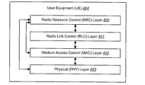
- Figure 7 is a block diagram illustrating the layers used by a user equipment (UE).
- Figure 8 is a flow diagram of a method for determining a highest priority channel state information (CSI) report.
- Figure 9 is a flow diagram of a method for collision resolution among transmission schedules of uplink control information (UCI).
- Figure 10 is a flow diagram of another method for collision resolution among transmission schedules of uplink control information (UCI).
- Figure 11 is a flow diagram of yet another method for collision resolution among transmission schedules of uplink control information (UCI).
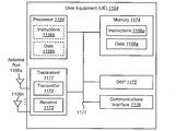
- Figure 12 illustrates various components that may be utilized in a user equipment (UE).
- Figure 13 illustrates various components that may be utilized in an eNode B.
- Figure 14 is a block diagram illustrating one configuration of one or more evolved Node Bs (eNBs) and one or more User Equipments (UEs) in which systems and methods for selecting a Channel State Information (CSI) report may be implemented.
- Figure 15 is a flow diagram illustrating one configuration of a method for selecting a CSI report.
- Figure 16 is a diagram illustrating one example of CSI report set generation.
- Figure 17 is a flow diagram illustrating a more specific configuration of a method for selecting a CSI report.
- Figure 18 is a diagram illustrating one example of selecting one or more CSI reports in accordance with alternative A.
- Figure 19 is a flow diagram illustrating another more specific configuration of a method for selecting a CSI report.
- Figure 20 is a diagram illustrating another example of selecting one or more CSI reports.
- Figure 21 is a diagram illustrating another example of selecting one or more CSI reports.
- Figure 22 illustrates various components that may be utilized in a UE.
- Figure 23 illustrates various components that may be utilized in an eNB.
- Figure 24 is a block diagram illustrating one configuration of a UE in which systems and methods for selecting a channel state information report may be implemented.
- Figure 25 is a block diagram illustrating one configuration of an eNB.
- One embodiment of the present invention discloses a method for collision resolution among transmission schedules of uplink control information (uci) .
- the present invention relates generally to wireless communications and wireless communications-related technology. More specifically, the present invention relates to systems and methods collision resolution among transmission schedules of uplink control information (UCI).
- UCI uplink control information
- a wireless communication system may provide communication for a number of cells, each of which may be serviced by a base station.
- a base station may be a fixed station that communicates with mobile stations.
- Various signal processing techniques may be used in wireless communication systems to improve efficiency and quality of wireless communication. Benefits may be realized by improved methods for reporting uplink control information (UCI) by a wireless communication device.
- UCI uplink control information
- the 3rd Generation Partnership Project also referred to as "3GPP," is a collaboration agreement that aims to define globally applicable technical specifications and technical reports for third and fourth generation wireless communication systems.
- the 3GPP may define specifications for the next generation mobile networks, systems and devices.
- 3GPP Long Term Evolution is the name given to a project to improve the Universal Mobile Telecommunications System (UMTS) mobile phone or device standard to cope with future requirements.
- UMTS has been modified to provide support and specification for the Evolved Universal Terrestrial Radio Access (E-UTRA) and Evolved Universal Terrestrial Radio Access Network (E-UTRAN).
- E-UTRA Evolved Universal Terrestrial Radio Access
- E-UTRAN Evolved Universal Terrestrial Radio Access Network
- At least some aspects of the systems and methods disclosed herein may be described in relation to the 3GPP LTE and LTE-Advanced standards (e.g., Release-8, Release-9, Release-10 and Release-11). However, the scope of the present disclosure should not be limited in this regard. At least some aspects of the systems and methods disclosed herein may be utilized in other types of wireless communication systems.
- a user equipment may be able to receive downlink signals from multiple geographically separated antennas (referred to herein as points).
- a point may be a set of geographically co-located antennas.
- a point may also be referred to as a site. Points may be located on or connected to the same base station or different base stations.
- uplink transmissions by the user equipment (UE) may be received by multiple points. Those points that transmit on the downlink to the user equipment (UE) may be referred to as transmission points. Those points that receive transmissions on the uplink from a user equipment (UE) may be referred to as reception points.
- a point may be capable of both transmission and reception.
- point refers to both transmission points and reception points. It is not necessary to use the same set of points for transmission to and reception from a given user equipment (UE).
- a subset of points participating in downlink transmission may be the same as or different from a subset of points participating in uplink reception (from the user equipment (UE)).
- Sectors of the same site may correspond to different points.
- a set of points that are involved in downlink transmission or uplink reception may change from one subframe to another.
- An antenna port may be defined such that the channel over which a symbol on the antenna port is conveyed can be inferred from the channel over which another symbol on the same antenna port is conveyed.
- Antenna ports can realize multiple layers for a multiple-input and multiple-output (MIMO) system.
- the points may be transparent to the user equipment (UE).
- UE user equipment
- antenna ports are distinguishable.
- An antenna port may be realized by an antenna or set of antennas in one point or a set of antennas in different points. However, points are distinguishable from the perspective of an eNode B. Therefore, in a transmission from a point to the user equipment (UE), from the perspective of the eNode B, the eNode B knows which point(s) are used for an antenna port participating in the transmission.
- the downlink performance can be significantly increased.
- the uplink reception at multiple reception points significant improvement in the uplink performance can be achieved.
- the channel state information (CSI) of each coordinated cell may be reported separately or jointly with the same format as Release-10 or new formats.
- Coordinated multipoint (CoMP) transmission and/or reception may increase uplink and downlink data transmission rates while ensuring consistent service quality and throughput on LTE wireless broadband networks and 3G networks.
- Coordinated multipoint (CoMP) transmission and/or reception may be used on both the uplink and the downlink.
- spontaneous may be used herein to denote a situation where two or more events occur in overlapping time frames.
- two “simultaneous” events may overlap in time to some extent, but are not necessarily of the same duration.
- simultaneous events may or may not begin or end at the same time.
- FIG. 1 is a block diagram illustrating a wireless communication system 100 that may utilize coordinated multipoint (CoMP).
- the wireless communication system 100 may include a serving eNode B 102a and a cooperating eNode B 102b as part of a system architecture evolution 101.
- the system architecture evolution 101 is a flat IP-based network architecture designed to replace the GPRS Core Network. In one configuration, the system architecture evolution 101 may be referred to as a core network.
- the eNode B 102 may have a channel state information reference signal (CSI-RS) transmit module 114.
- the CSI-RS transmit module 114 may include channel state information reference signals (CSI-RS) 116, channel state information reference signal (CSI-RS) configurations 118 and channel state information (CSI) report configurations 120.
- the eNode B 102 may send the CSI-RS 116 to the user equipment (UE) 104, for instance, to be measured.
- CSI-RS may refer to a single CSI-RS and/or multiple CSI-RSs.
- the CSI-RS transmit module 114 may generate CSI-RS configurations 118.
- the eNode B 102 may then send the CSI-RS configuration 118 to the user equipment (UE) 104.
- the user equipment (UE) 104 may use the received CSI-RS configurations 118 to detect and process the CSI-RS 116 transmitted to it.
- the user equipment (UE) 104 may store the received CSI-RS configurations 118 in the CSI-RS configuration module 152.
- the eNode B 102 may send the channel state information (CSI) report configurations 120 to the user equipment (UE) 104 so that the user equipment (UE) 104 may generate CSI reports to be sent back to the eNode B 102.
- each channel state information (CSI) report configuration 120 may also include information about which CSI-RS(s) 116 should be used to be reported.
- the user equipment (UE) 104 may store the received CSI report configurations 120 in the CSI report configuration module 158.
- An eNode B 102 is a physical structure that may include multiple antennas. Some of the antennas may be co-located with an eNode B 102 and other antenna ports may be geographically separated from an eNode B 102. Both the co-located antennas and the geographically separated antennas may be referred to as points 110. Some of the points 110a-b may be associated with the serving eNode B 102a while other points 110c may be associated with a cooperating eNode B 102b. The eNode Bs 102 may use the points 110 to coordinate downlink 108 transmission to and uplink 106 reception from a user equipment (UE) 104. If a point 110c is connected to a cooperating eNode B 102b, there may be a backhaul interface 144 connecting the cooperating eNode B 102b to the serving eNode B 102a.
- UE user equipment
- a point 110 may be an antenna and or antenna port associated with a base station.
- a base station may be referred to as an access point, a transmission point, a Node B, an eNode B, a transmission node, a node or some other terminology.
- a point 110 may be collocated with a base station or geographically separated from the base station.
- a user equipment (UE) 104 may be referred to as a mobile station, a subscriber station, an access terminal, a remote station, a user terminal, a terminal, a handset, a subscriber unit, a wireless communication device or some other terminology.
- Communication between a user equipment (UE) 104 and an eNode B 102 may be accomplished using transmissions over a wireless link, including an uplink 106 and a downlink 108.
- the uplink 106 refers to communications sent from a user equipment (UE) 104 to a device in the system architecture evolution 101 (e.g., an eNode B 102).
- the downlink 108 refers to communications sent from the system architecture evolution 101 (e.g., an eNode B 102) to a user equipment (UE) 104.
- An eNode B 102 may use different combinations of points 110 to send downlink 108 signals to a user equipment (UE) 104 and receive uplink 106 signals from the user equipment (UE) 104.
- the communication link may be established using a single-input and single-output (SISO), multiple-input and single-output (MISO), single-input and multiple-output (SIMO) or a multiple-input and multiple-output (MIMO) system.
- a MIMO system may include both a transmitter and a receiver equipped with multiple transmit and receive antennas.
- a base station may have multiple antennas (or points 110) and a user equipment (UE) 104 may have multiple antennas (not shown).
- UE user equipment
- UE user equipment
- One benefit of a MIMO system is improved performance if the additional dimensionalities created by the multiple transmit and receive antenna ports realized by the multiple transmit and receive antennas are utilized.
- Carrier aggregation refers to transmitting data on multiple component carriers (CCs) (or cells) that are contiguously or separately located.
- CCs component carriers
- the downlink 108 transmission from multiple points 110 to a single user equipment (UE) 104 may be referred to as coordinated multipoint (CoMP) transmission operation.
- the uplink 106 transmission from a user equipment (UE) 104 to multiple reception points 110 may be referred to as coordinated multipoint (CoMP) reception operation.
- one transmission method is joint transmission (JT) as stated by 3GPP Release-10 specification.
- JT joint transmission
- all participating transmission points (TPs) 110 transmit the same unencoded data.
- all the TPs 110 may transmit the same coded data and the user equipment (UE) 104 receives and combines the signals at the user equipment (UE) 104.
- the received signals may be combined or super imposed on the user equipment (104) prior to any processing being performed by the user equipment (UE) 104.
- All points 110 transmitting coordinated multipoint (CoMP) signals to a user equipment (UE) 104 may be referred to as CoMP transmission points (TPs) 110 or transmission points (TPs) 110.
- All points 110 receiving coordinated multipoint (CoMP) signals from a user equipment (UE) 104 may be referred to as CoMP reception points 110 or reception points 110.
- the point 110 may transmit a reference signal over the downlink 108 to the user equipment (UE) 104.
- Each of the points 110 may use a channel state information reference signal (CSI-RS) transmit module114 to transmit the reference signal to the user equipment (UE) 104.
- CSI-RS channel state information reference signal
- points 110 may use cell-specific reference signals (CRS), multimedia broadcast over a single frequency network (MBSFN) reference signals, UE-specific reference signals (e.g., a demodulation reference signal (DM-RS)), positioning reference signals (PRS) and channel state information reference signals channel state information reference signal (CSI-RS).
- CRS cell-specific reference signals
- MMSFN single frequency network
- UE-specific reference signals e.g., a demodulation reference signal (DM-RS)
- PRS positioning reference signals
- CSI-RS channel state information reference signals channel state information reference signal
- the frequency bandwidth may be partitioned in subcarriers with equal bandwidth.
- Time may be divided into intervals with equal durations known as the symbol period.
- the temporal duration of a time-frequency resource grid is 10 milliseconds (ms) (referred to as one radio frame).
- One radio frame may include 10 subframes, each with a duration of 1 ms, which is the duration of transmission in the uplink 106 and/or downlink 108. Every subframe may be divided into two slots, each with a duration of 0.5 ms.
- the minimum amount of resource that can be allocated for the transmission of information in the uplink 106 or downlink 108 in any given subframe is two resource blocks (RBs), with one RB at each slot.
- Each slot may be divided into 7 symbols.
- the frequency domain may be divided into bands with a 15 kilohertz (kHz) width, referred to as a subcarrier.
- one RB has a duration of 0.5 ms (7 symbols or one slot) in the time domain and a bandwidth of 12 subcarriers (180 kHz) in the frequency domain.
- One resource element has a duration of one symbol in the time domain and the bandwidth of one subcarrier in the frequency domain.
- a maximum of two RBs can be used by a given user equipment (UE) 104 for the transmission of uplink control information (UCI) in the physical uplink control channel (PUCCH).
- UCI uplink control information
- PUCCH physical uplink control channel
- the points 110 participating in the transmission of reference signals to the user equipment (UE) 104 may belong to the coordinated multipoint (CoMP) measurement set.
- the coordinated multipoint (CoMP) measurement set may be defined as the set of points 110 about which channel state/statistical information related to their link to the user equipment (UE) 104 is measured and/or reported.
- the transmission of reference signals in the downlink 108 may or may not occur in a coordinated multipoint (CoMP) transmission setting.
- a cooperating set refers to a set of geographically and/or virtually separated points 110 directly and/or indirectly participating in data transmission to a user equipment (UE) 104 in a time-frequency resource and/or data reception from a user equipment (UE) 104 in a time-frequency resource.
- the set of transmission and/or reception points 110 is a subset of the cooperating set.
- the cooperating set may or may not be transparent to the user equipment (UE) 104.
- the user equipment (UE) 104 may include one or more channel state information (CSI) modules 150.
- each component carrier (CC) may have a channel state information (CSI) module 150.
- the channel state information (CSI) module 150 may include one or more channel state information (CSI) configuration modules 152, one or more channel state information (CSI) measurement modules 154, one or more channel state information (CSI) report generation modules 156, one or more channel state information (CSI) report configuration modules 158 and a channel state information (CSI) report collision resolution modules 160.
- CSI channel state information
- CSI channel state information
- CSI channel state information
- CSI channel state information
- CSI channel state information
- CSI channel state information
- CSI channel state information
- CSI channel state information
- CSI channel state information
- CSI channel state information
- CSI channel state information
- CSI channel state information
- CSI channel state information
- CSI channel state information
- CSI channel state information
- CSI channel state information
- CSI channel state information
- CSI channel state information
- CSI channel state information
- CSI channel state information
- CSI channel state information
- CSI channel state information
- CSI channel state information
- CSI channel state information
- the channel state information (CSI) configuration module 152 may receive a CSI-RS configuration from eNode B 102.
- the CSI-RS configuration includes CSI-RS sequence, periodicity, antenna port from which the CSI-RS is transmitted and the pattern of resource elements occupied by the CSI-RS symbols.
- a configured CSI-RS with a particular configuration is referred to as CSI-RS resource.
- the reference signal sequence of a configured CSI-RS resource is transmitted on a carrier, or component carrier, occupying the time and frequency resources determined by the CSI-RS configuration.
- the CSI-RS configuration may inform the user equipment (UE) 104 about the configuration of the CSI-RS received at the user equipment (UE) 104. For example, if there were multiple eNode Bs 102 using the same component carrier (CC) or cell, as may be the case with coordinated multipoint (CoMP) measurement, then each channel state information (CSI) configuration module 152 may receive a CSI-RS configuration and may apply the CSI-RS configuration to the received CSI-RS signal. In other words, multiple CSI-RS may be configured.
- the CSI-RS configuration may be performed by radio resource control (RRC) signaling.
- RRC radio resource control
- the serving eNode B 102 configures the user equipment (UE) 104 with one or more CSI-RS in a given carrier component.
- CSI-RS The association of CSI-RS to other eNode Bs and/or other transmission points might be transparent to the user equipment (UE) 104.
- One parameter that is used for configuring CSI-RS resources is the identification number associated to a cell, known as the cell-ID. All the configured CSI-RS may or may not belong to the same serving cell. In other words, one or more CSI-RS resources may be configured with cell-ID(s) different from the user equipment's (user equipment (UE's) serving cell cell-ID. In one configuration, CSI-RS are indexed. The CSI-RS index may be used for prioritization.
- the channel state information (CSI) module 150 may have two channel state information (CSI) configuration modules 152 that each include a CSI-RS configuration (e.g., CSI-RS 1 configuration and CSI-RS 2 configuration).
- CSI-RS configuration e.g., CSI-RS 1 configuration and CSI-RS 2 configuration.
- the channel state information (CSI) measurement module 154 may measure the channel state information (CSI) for each configured CSI-RS.
- CSI-RS1 may be transmitted according to the periodicity and resource elements pattern as indicated by CSI-RS 1 configuration.
- channel state information (CSI) measurement module 154 may measure the channel state information (CSI) based on the received symbols on the resource elements on which the CSI-RS1 is transmitted.
- the user equipment (UE) 104 may obtain a channel state information (CSI) measurement for each CSI-RS.
- the user equipment (UE) 104 may be able to obtain multiple CSI measurements when multiple CSI-RS are configured.
- the CSI report configuration may identify which CSI-RS(s) should be measured and/or reported In Release 10 radio resource control (RRC) specification, the CSI report configuration is referred to as CQIReportConfig.
- the channel state information (CSI) report generation module 156 may generate channel state information (CSI) reports.
- the channel state information (CSI) reports may be generated according to a channel state information (CSI) report configuration, which is set by the channel state information (CSI) report configuration module 158.
- the channel state information (CSI) reports may be sent back to the eNode B 102 having one or more transmission points 110.
- multiple channel state information (CSI) reports may need to be generated and sent back to the serving eNode B 102 (or central scheduler).
- the channel state information (CSI) report generation modules 156 may be derived by a CSI report configuration, which may be set by the CSI report configuration module 158.
- One channel state information (CSI) report generation module 156 may correspond to the one or more CSI-RS(s) depending on CSI report configuration.
- the CSI report configuration, set by the CSI report configuration module 158 may identify which CSI-RS(s) should correspond to the channel state information (CSI) report generation module 156. For example, if there are two CSI Report configurations, for the same carrier (or component carrier, or carrier frequency) or for the same serving cell, then there will be at least two channel state information (CSI) report generation modules 156.
- One channel state information (CSI) report generation module 156 will correspond with CSI Report Configuration 1.
- Another channel state information (CSI) report generation module 156 will correspond with CSI Report Configuration 2.
- the CSI report generation module 156 may generate CSI reports from CSI measurements performed by the CSI measurement module 154.
- the CSI reports may be based on the CSI report configuration, which may be set by the CSI report configuration module 158.
- the channel state information (CSI) report may be based on a variety of channel state information (CSI) measurements.
- the channel state information (CSI) report configuration may be based on channel quality indicators (CQI).
- CQI channel quality indicators
- the CSI report may be a CQI report.
- Each channel state information (CSI) report configuration may include information about what should be reported and when it should be reported.
- the channel state information (CSI) report configuration may set the periodicity for reporting a channel quality indication (CQI) and a precoding matrix indication (PMI) as well as the periodicity for reporting the rank indication (RI).
- the channel state information (CSI) report configuration may indicates that channel quality indications (CQI) should be reported every 5 milliseconds (ms) and rank indications (RI) should be reported every 20 milliseconds (ms).
- Each channel state information (CSI) report configuration may also include information about which CSI-RS(s) should be reported.
- the channel state information (CSI) report generation module 156 may generate reports based on channel state information (CSI) measurement. Each generated report is identified by a report type (also referred as to PUCCH reporting type, PUCCH CSI reporting type, CSI reporting type, etc.).
- a report type indicates a specific combination of channel state information (CSI) information to be reported. For example, one type, denoted by TypeA, may include wideband CQI and PMI and another type, denoted by TypeB, may include RI.
- the channel state information (CSI) report configuration determines what should be reported. Because different measurements (such as CQI, PMI and RI) may have different periodicities, two or more types may be chosen to be reported at the same time slot.
- CSI channel state information
- the user equipment (UE) 104 is configured with only one CSI-RS with non-zero power for estimating the channel state information of a given component carrier and has only one channel state information (CSI) report generation module 156 corresponding to the configured CSI-RS.
- CSI channel state information
- coordinated multipoint (CoMP) operation may introduce more than one CSI-RS configuration.
- CSI channel state information
- the colliding channel state information (CSI) reports might belong to the same measurement corresponding to a single CSI-RS, to different CSI-RSs or to aggregated measurement (e.g., a channel state information measurement performed on combination of the estimated channels by different CSI-RSs, or the CSI measurement of a CSI-RS that is transmitted from multiple points).
- CSI channel state information
- the channel state information (CSI) report collision resolution module 160 may resolve collision between channel state information (CSI) reports in the same serving cell.
- the serving cell in this content (CoMP CSI measurement) is referring to a component carrier.
- CSI-RS1 may be transmitted on the component carrier 1 from the user equipment's (UE) serving cell and CSI-RS2 may be transmitted on the same component carrier 1 from the user equipment's (UE) neighboring cell, which has a different cell-ID. Note that as long as the user equipment (UE) 104 is not aware of the association between CSI-RS and the cell, the measurement and reporting could be agnostic and transparent to such association.
- the output of the channel state information (CSI) report collision resolution module 160 may be a single channel state information (CSI) report to be fed back.
- the channel state information (CSI) report collision resolution module 160 may resolve collision based on various prioritizations, such as reporting-type, reporting-configuration and/or the serving cell index.
- the channel state information (CSI) report collision resolution module 160 may also resolve collisions between channel state information (CSI) reports from different serving cells, or different component carriers. In this way, collisions may be resolved within each serving cell and among multiple serving cells within the user equipment (UE) 104.
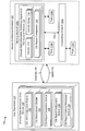
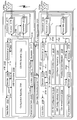
- Figure 2 is a block diagram illustrating one configuration of CSI-RS resources, measurements and reporting in a user equipment (UE) 104 serving cell.
- UE user equipment
- component carrier 1 101a and component carrier 2 110 may each represent a serving cell.
- component carrier 1 (or serving cell) 101a may be applied to component carrier 2 (or serving cell) 101b, respectively.
- the user equipment (UE) 104 may include a CSI-RS 1-1 107a and a CSI-RS 1-2 109a, which are configured by a CSI-RS configuration 1-1 103a and a CSI-RS configuration 1-2 105a, respectively.
- the CSI-RS configuration 103a and 105a of Figure 2 may be examples of the CSI-RS configuration module 152 discussed in connection with Figure 1.
- the user equipment (UE) 104 may include a CSI measurement 1-1 115a, a CSI measurement 1-2 119a and an aggregate channel state information (CSI) measurement 1 117a.
- the CSI measurements modules 115a, 117a and 119a of Figure 2 may be examples of the CSI-RS measurement module 154 discussed in connection with Figure 1.
- the user equipment (UE) 104 may include a channel state information (CSI) report generator 129a and a corresponding CSI report configuration 1 127a.
- the channel state information (CSI) report generator 1 129a of Figure 2 may be part of the CSI report generation module 156 discussed in connection with Figure 1.
- the channel state information (CSI) report configuration 1 127a of Figure 2 may be part of the CSI report configuration module 158 discussed in connection with Figure 1.
- the user equipment (UE) 104 may include a single cell collision resolution module 153a and a multi cell resolution module 157.
- the single cell collision resolution module 153a and/or a multi cell resolution module 157 may be part of the CSI report collision resolution module 160 discussed in connection with Figure 1.
- the user equipment (UE) 104 may receive a signal on a component carrier (CC) 1 (or serving cell) 101a.
- the signal may be a channel state information reference signal (channel state information reference signal (CSI-RS)).
- CSI-RS channel state information reference signal
- CoMP coordinated multipoint
- multiple CSI-RS may be received, where each CSI-RI may belong to the UE's serving cell or a neighboring cell.
- CSI-RS 1-1 107a and CSI-RS 1-2 109a may be received.
- CSI-RS 1-X refers to the Xth configured CSI-RS for component carrier (CC) 1 101a.
- CSI-RS 2-2 109b refers to the second configured CSI-RS for component carrier 2 101b.
- Each CSI-RS (e.g., CSI-RS 1-1 107a and CSI-RS 1-2 109a) may correspond with a CSI-RS configuration (CSI-RS configuration 1-1 103a and CSI-RS configuration 1-2 105a, respectively).
- the CSI-RS configuration may include CSI-RS sequence, periodicity, antenna port from which the CSI-RS is transmitted and the pattern of resource elements occupied by the CSI-RS symbols and may be set by the eNode B 102.
- the CSI-RS configuration may inform the user equipment (UE) 104 about the configuration of the received CSI-RS (e.g., CSI-RS 1-1 107a and CSI-RS 1-2 109a).
- CSI-RS 1-1 107a may be transmitted by the eNode B 102 according to the periodicity and resource elements pattern as indicated by CSI-RS 1-1
- the user equipment (UE) 104 may receive a CSI-RS configuration (e.g., CSI-RS configuration 1-1 103a and CSI-RS configuration 1-2 105a) via RRC signaling from the eNode B 102 and may apply the CSI-RS configuration (e.g., CSI-RS configuration 1-1 103a and CSI-RS configuration 1-2 105a) to the received signal (e.g., CSI-RS 1-1 107a and CSI-RS 1-2 109a) in order to perform the channel state information measurement, synchronization
- CSI-RS configuration 1-1 103a and CSI-RS configuration 1-2 105a e.g., CSI-RS configuration 1-1 103a and CSI-RS configuration 1-2 105a
- each channel state information reference signal (CSI-RS) 1-1 107a, 1-2 109a may have each have their own dedicated channel state information (CSI) report configuration. This will be described below in Figure 4.
- each CSI reference signals (CSI-RS) 1-1 107a, 1-2 109a may share a single channel state information (CSI) report configuration 1 127a.
- the user equipment (UE) 104 may measure the channel state information (CSI) for each CSI-RS (e.g., CSI-RS 1-1 107a and CSI-RS 1-2 109a) transmitted in each component carrier 101a.
- CSI-RS 1-1 107a and CSI-RS 1-2 109a may be measured to obtain CSI measurement 1-1 115a and CSI measurement 1-2 119a.
- Aggregate channel state information (CSI) measurement 1 117a may also be obtained by measuring the channel state information of an aggregated channel.
- the user equipment (UE) 104 may assume a combined channel, which is calculated by superposition (e.g., addition) of the received signals from multiple configured CSI-RSs at the user equipment (UE) 104.
- the aggregated channel may be derived by a superposition of all, or a subset, of the configured CSI-RSs.
- the aggregated channel state information may be measured by the multiple CSI-RSs while the user equipment (UE) 104 assumes there is the aggregated channel.
- the aggregate CSI measurement 1 117a may be obtained independent of CSI-RS 1-1 107a and CSI-RS 1-2 109a by allocating a CSI-RS dedicated for measuring the aggregated channel state information (CSI). This may require a separate CSI-RS configuration dedicated for the aggregated CSI measurement 1 117a.
- Each channel state information (CSI) measurement may send channel state information (CSI) such as channel quality indicators (CQI), a precoding matrix indicators (PMI), precoding type indicators (PTI), rank indicators (RI), etc.
- CSI channel state information
- CQI channel quality indicators
- PMI precoding matrix indicators
- PTI precoding type indicators
- RI rank indicators
- the CSI measurement 1-1 115a, aggregate CSI measurement 117a and CSI measurement 1-2 119a may send channel state information (CSI), 121a, 123a and 125a, respectively, to a channel state information (CSI) report generator 129a.
- the channel state information (CSI) report generator 129a may generate channel state information (CSI) reports.
- Channel state information (CSI) reports may be in Rx-y-z format, where x is serving cell index, y is CSI report configuration index and z is report index. Thus, z may describe the number of the reports generated at a subframe.
- R1-1-3 refers to the third report generated corresponding to the first CSI-RS of the first serving cell.
- channel state information (CSI) reports may be made in Rx-z format.
- channel state information (CSI) report generator 129a may generate three channel state information (CSI) reports, R1-1 139a, R1-2 141a and R1-3 143a, corresponding to CSI measurement 1-1 115a, aggregate CSI measurement 117a and CSI measurement 1-2 119a may send channel state information (CSI), respectively.
- the channel state information (CSI) report generator 129a may obtain directions from CSI report configuration 1 127a.
- CSI report configuration 1 127a may be set by the eNode B 102.
- the CSI report configuration 1 127 may be a CQI report configuration.
- Figure 2 illustrates, in each component carrier, two CSI-RS (e.g., 107 and 109), three CSI measurement modules (e.g., 115, 117 and 119) and one CSI report generator 129 with a corresponding CSI report configuration 127.
- K represents any positive integer
- each CSI report generator may have a corresponding report configuration and the number of CSI report generators may be 1, K or K+n and need not to be K.
- the user equipment (UE) 104 may resolve collisions from the multiple channel state information (CSI) Reports R1-1 139a, R1-2 141a and R1-3 143a at a single cell collision resolution module 153a.
- the single cell collision resolution module 153a may resolve collisions by using priorities based on report-type and/or report-configuration. For example, if the single cell collision resolution module 153a is using report-configuration, the single cell collision resolution module 153a may give a channel state information (CSI) reports with a lower CSI report configuration index (e.g., z) higher priority of a channel state information (CSI) report with a higher CSI report configuration index, or vise-versa.
- CSI channel state information
- the user equipment (UE) 104 may resolve multi-component carrier collisions with a multi cell resolution module 157.
- the multi cell resolution module 157 may receive the highest channel state information (CSI) reports 155a and 155b for each component carriers (CC) 101 and determine the channel state information (CSI) report with the highest priority 159.
- the channel state information (CSI) report with the highest priority 159 may then be transmitted to the eNode B 102.
- multi cell resolution module 157 may determine priority based on which serving cell or component carriers (CC) 101 has the lowest serving cell index.
- the multi cell resolution module 157 would determine the channel state information (CSI) report 155a from component carrier 1(CC) 101a to be the highest priority 159 channel state information (CSI) report because component carrier 1 101a has a lower serving cell index (i.e., 1) than the serving cell index (i.e., 2) of component carrier 2 101b.
- the priority order of cell index and/or the report-configuration may be set a priori or may be configured by eNode B via radio resource control (RRC) signaling.
- RRC radio resource control
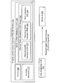
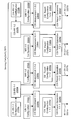
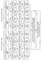
- FIG 3 is a block diagram illustrating a wireless communication system 200 using uplink control information (UCI) multiplexing.
- An eNode B 202 may be in wireless communication with one or more user equipments (UEs) 204.
- the eNode B 202 may be an example of the eNode B 102 described in connection with Figure 1.
- the eNode B 202 may be part of a coordinated multipoint (CoMP) system.
- the eNode B 202 may be a serving eNode B 102a or a cooperating eNode B 102b.
- CoMP coordinated multipoint
- the user equipment (UE) 204 may be an example of the user equipment (UE) 104 described in connection with Figure 1.
- the user equipment (UE) 204 may include an uplink channel information (UCI) reporting module 214.
- the UCI reporting module 214 may include a CSI report 236 and channel state information (CSI) 241.
- the UCI reporting module 214 of Figure 3 may be one example of and/or include the CSI module 150 of Figure 1.
- the CSI report generation module 156 of Figure 1 may generate the CSI report 236 of Figure 3.
- the user equipment (UE) 204 communicates with an eNode B 202 using one or more antenna ports, which may be realized by one or more physical antennas 299a-n.
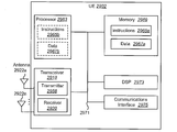
- the user equipment (UE) 204 may include a transceiver 217, a decoder 227, an encoder 231 and an operations module 233.
- the transceiver 217 may include a receiver 219 and a transmitter 223.
- the receiver 219 may receive signals from the eNode B 202 using one or more antenna ports, which may be realized by one or more physical antennas 299a-n. For example, the receiver 219 may receive and demodulate received signals using a demodulator 221.
- the transmitter 223 may transmit signals to the eNode B 202 using one or more antenna ports, which may be realized by one or more physical antennas 299a-n.
- the transmitter 223 may modulate signals using a modulator 225 and transmit the modulated signals.
- the receiver 219 may provide a demodulated signal to the decoder 227.
- the user equipment (UE) 204 may use the decoder 227 to decode signals and make downlink decoding results 229.
- the downlink decoding results 229 may indicate whether data was received correctly.
- the downlink decoding results 229 may indicate whether a packet was correctly or erroneously received (i.e., positive acknowledgement, negative acknowledgement or discontinuous transmission (no signal)).
- the receiver 219 may receive one or more coordinated multipoint (CoMP) transmitting signals.
- CoMP coordinated multipoint
- the user equipment (UE) 204 may include multiple component carrier 101 and each component carrier 101 may receive signals from one or more transmission points 110 and the cells associated to the component carrier 101 from different transmission points may represent a single serving cell, having the same cell-ID, or they may have different cell-ID in which one cell is referred to as serving cell and other cells are referred to as neighboring cell. Also note that in case that there are one serving cell and one or more neighboring cell, all cells may be process in a single eNode B 102 or in more than one eNode B 102a-b.
- the operations module 233 may be a software and/or hardware module used to control user equipment (UE) 204 communications. For example, the operations module 233 may determine when the user equipment (UE) 204 requires resources to communicate with the eNode B 202.
- the user equipment (UE) 204 may transmit uplink control information (UCI) to an eNode B 202 on the uplink.
- the uplink control information (UCI) may be channel state information (CSI) 241 and may include a channel quality indicator (CQI), a precoding matrix indicator (PMI), precoding type indication (PTI), rank indication (RI), a scheduling request (SR), etc.
- CQI channel quality indicator
- PMI precoding matrix indicator
- PTI precoding type indication
- RI rank indication
- SR scheduling request
- the channel quality indicator (CQI) may indicate a combination of modulation scheme and coding rate.
- the precoding matrix indicator (PMI) indicates the codebook for precoding the MIMO transmission.
- the precoding type indication (PTI) indicates the precoding type.
- the rank indication (RI) indicates the number of useful transmission layers for the MIMO transmission.
- CQI channel quality indicator
- WB-CQI wideband feedback
- UE-CQI UE-selected subband feedback
- WB-CQI wideband feedback
- UE-CQI UE-selected subband feedback
- the user equipment (UE) may report one wideband channel quality indicator (CQI) value for the whole system bandwidth.
- UE-selected subband feedback UE-CQI
- the user equipment (UE) may report the channel quality indicator (CQI) for some subbands instead of the whole system bandwidth.
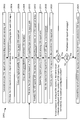
- the system bandwidth may be divided into J bandwidth parts, as illustrated in Table 1.
- the channel state information (CSI) 241 may be separately coded. In another configuration, the channel state information (CSI) 241 may be jointly coded.
- CQI/PMI/PTI/RI refers to CQI and/or PMI and/or PTI and/or RI.
- the CQI and/or PMI and/or PTI and/or RI may be reported together or independently based on the physical uplink control channel (PUCCH) reporting modes.
- the CQI/PMI/PTI/RI may be collectively referred to as channel state information (CSI) 241.
- a channel state information (CSI) report thus may include a CQI/PMI/PTI/RI report.
- Channel state information (CSI) 241 reporting from a user equipment (UE) 204 to an eNode B 202 may be periodic or aperiodic.
- Aperiodic channel state information (CSI) reports may be requested by an eNode B 202.
- Periodic channel state information (CSI) reports may be configured by an eNode B 202, so that the user equipment (UE) 204 reports channel state information (CSI) 241 to the eNode B 202 at pre-specified subframes.
- the channel state information (CSI) report 236 may be generated by the uplink control information (UCI) reporting module 214 and transferred to a channel state information (CSI) encoder 256 that is part of the encoder 231.
- the channel state information (CSI) encoder 256 may generate uplink control information (UCI) using backwards-compatible physical uplink control channel (PUCCH) formats.
- Backwards-compatible physical uplink control channel (PUCCH) formats are those formats that may be used by Release-10 user equipments (UEs) 204 as well as Release-8/9 user equipments (UEs) 204.
- the channel state information (CSI) report 236 may also include the number of antenna ports.
- a channel state information (CSI) report 236 may correspond to eight antenna ports, four antenna ports or two antenna ports.
- a channel state information (CSI) report 236 may further include the corresponding component carrier (CC) 208 (or cell 285) of the channel state information (CSI) report 236.
- This may allow the channel state information (CSI) selection module 257 to prioritize channel state information (CSI) reports 236 using radio resource control (RRC) based prioritization that is signaled by higher layers 218.
- Radio resource control (RRC) based prioritization refers to a predefined component carrier (CC) 208 prioritization rule that specifies the priority ordering of component carriers (CCs) 208 (e.g., CC1 > CC2 > CC3).
- a channel state information (CSI) report 236 may further include a priority number.
- a priority number may be defined. In increasing order, the priority goes lower (i.e., a lower priority number has a higher priority).
- the priority numbers may be defined according to the reporting mode, the feedback reporting type(also referred as to PUCCH reporting type, PUCCH CSI reporting type, CSI reporting type etc.), the number of antenna ports and the rank indication (RI).
- the channel state information (CSI) encoder 256 may include a channel state information (CSI) selection module 257.
- a user equipment (UE) 204 does not simultaneously transmit on the physical uplink control channel (PUCCH) and the physical uplink shared channel (PUSCH). Only one channel state information (CSI) report 236 may be transmitted on the physical uplink control channel (PUCCH).
- the channel state information (CSI) selection module 257 may be used to determine which channel state information (CSI) report 236 should be transmitted on the physical uplink control channel (PUCCH).
- the channel state information (CSI) selection module 257 may receive multiple channel state information (CSI) reports 236. The channel state information (CSI) selection module 257 may then determine a highest priority channel state information (CSI) report 251 from among the multiple channel state information (CSI) reports 236.
- CSI channel state information
- the channel state information (CSI) selection module 257 may use one or more of the feedback reporting mode also referred as to PUCCH reporting mode, PUCCH CSI reporting mode, PUCCH CSI reporting mode, CSI reporting mode etc.), the feedback reporting type (also referred as to PUCCH reporting type, PUCCH CSI reporting type, CSI reporting type, etc.), the number of antenna ports, the corresponding component carrier (CC) 208 (or cell 285) of the channel state information (CSI) report 236 and/or the priority number to determine the highest priority channel state information (CSI) report 251.
- the channel state information (CSI) selection module 257 may prioritize the channel state information (CSI) reports 236 based on the feedback reporting mode followed by the feedback reporting type.
- the channel state information (CSI) reports 236 received by the channel state information (CSI) selection module 257 that are not selected as the highest priority channel state information (CSI) report 251 may then be dropped by the channel state information (CSI) selection module 257.
- One resource of the physical uplink control channel may be allocated for transmission of the uplink control information (UCI), with collision resolution procedures resolving any collision issues.
- UCI uplink control information
- CSI channel state information
- a collision resolution procedure may be used to determine the resource and format used for transmission.
- the physical uplink control channel (PUCCH) for channel state information (CSI) 241 may be semi-statically scheduled by an eNode B 202, but the physical uplink control channel (PUCCH) may be dynamically allocated based on downlink configurations and transmission.
- the uplink control information (UCI) may be transmitted using the physical uplink control channel (PUCCH).
- the uplink control information such as periodic channel quality indicators (CQI), periodic precoding matrix indicator (PMI) and periodic rank indication (RI) can be sent on the physical uplink control channel (PUCCH).
- the physical uplink control channel (PUCCH) may occupy one resource block (RB) at each slot. Thus, a very limited amount of information can be transmitted on the physical uplink control channel (PUCCH).
- each user equipment (UE) 204 is configured with a cell specific CSI-RS configuration with non-zero power.
- Each CSI-RS configuration determines the reference signal sequence, the periodicity of the transmission of the reference signal, the resource elements allocated for transmission of the reference signal and the antenna port allocated for the transmission of the reference signal.
- each user equipment (UE) 204 reporting parameters are configured in a UE-specific way. The reporting configuration determines the periodicity of each CSI measurement (e.g., CQI/PMI/PTI/RI)
- Carrier aggregation was introduced. Carrier aggregation may also be referred to as cell aggregation. Carrier aggregation is supported in both the uplink and the downlink with up to five component carriers (CCs) 206, 208. Each component carrier (CC) 206, 208 or cell 285 may have a transmission bandwidth of up to 210 resource blocks (i.e., up to 20 megahertz (MHz)). In carrier aggregation, two or more component carriers (CCs) 206, 208 are aggregated to support wider transmission bandwidths up to one hundred megahertz (MHz). A user equipment (UE) 204 may simultaneously receive and/or transmit on one or multiple component carriers (CCs) 206, 208, depending on the capabilities of the user equipment (UE) 204.
- CCs resource blocks
- cyclic reporting of periodic CSI e.g., CQI/PMI/PTI/RI
- CQI/PMI/PTI/RI periodic channel state information
- CSI periodic channel state information
- PUCCH physical uplink control channel
- the eNode B 202 may perform centralized scheduling of a multitude of cells.
- the physical transmission of information may take place from one Transmission Point (TP) 110 or many TPs 110a-c. Different TPs 110a-c may transmit information in the downlink 208 on different carriers 206 (or cells 285).
- TP Transmission Point
- Different TPs 110a-c may transmit information in the downlink 208 on different carriers 206 (or cells 285).
- TPs 110 serve the same user equipment (UE) 204 in the same carrier 206, it is referred to as Coordinated Multipoint (CoMP) Transmission.
- the downlink transmission from two different TPs 110 may or may not have the same cell-ID. If they do not have the same cell-ID then one of them is the serving cell and the other is a neighboring cell.
- the transmission/reception points have the same cell IDs as the macrocell 657, it is commonly understood that all the transmission points transmit the same cell-specific reference signal (CRS) but can transmit different channel state information reference signals (CSI-RSs).
- CRS cell-specific reference signal
- CSI-RSs channel state information reference signals
- the transmission parameters such as pre-coding and/or coding and modulation scheme
- the eNode B 202 may employ channel state information (CSI) 241 of the aggregated channel.
- CSI channel state information
- First-RS and Second-RS may refer to a first and second reference signal (RS).
- the CSI-RS configuration of First-RS and Second-RS may refer to as first and second reference signal (RS) configuration.
- First-RS configuration may refer to the single CSI-RS configuration that existed previously, i.e. Release 10 of 3GPP specification.
- First-RS and Second-RS may be configured to transmit First-RS and Second-RS channel state information (CSI) reports 236, respectively.
- First-RS and Second-RS correspond to CSI-RS index in CSI-RS configuration.
- Enabling 3GPP Release-11 specification and future releases of 3GPP systems with the transmission of aggregated (e.g., combined, composite or effective) and per-CSI-RS (non-aggregated) CSI may be beneficial by increasing the system throughput and increasing resource utilization by enabling flexible scheduling.
- the channel state information (CSI) 241 may need to be modified to be able to give proper measurements and feedback to the eNode B 202.
- the channel state information (CSI) 241 may be modified to include aggregate measurements, such as an aggregated Channel Quality Indicator (agg_CQI), aggregated Precoding Matrix Indicator (agg_PMI), aggregated Precoding Type Indicator (agg_PTI) and aggregated Rank Indicator (agg_RI).
- aggregated CSI information may be referred to as agg_CSI. It should be noted that agg_CSI is measured when two or more TPs 110 use the same carrier for a downlink 208 transmission.
- new channel state information (CSI) 241 such as relative phase and relative amplitude may be added.
- Relative phase and relative amplitude may be referred to as INTER-CSI-RS-PHASE and INTER-CSI-RS-AMPLITUDE, respectively.
- INTER-CSI-RS-PHASE may measure the relative phase of the received signals between a reference transmission point (TP) 110a (or channel state information reference signal (CSI-RS)) and another TP 110c (or CSI-RS).
- CSI-RS-AMPLITUDE may measure the relative amplitude of the received signals from a reference TP or point 110a (or CSI-RS) and another TP or point 110c (or CSI-RS).
- CSI channel state information
- CC component carrier
- CSI channel state information
- UE user equipment
- UCI uplink control information
- Some collision resolution procedures have already been defined in 3GPP Release-10 specifications. Additional collision resolution procedures in 3GPP Release-11 specification and future releases of 3GPP may be needed. For example, in Coordinated Multipoint (CoMP) transmissions, collision resolution due to new Uplink Control Information (UCI) may need to be specified.
- CoMP Coordinated Multipoint
- CSI reports 236 Due to the low payload size of the physical uplink control channel (PUCCH), some of the channel state information (CSI) reports 236 may be dropped during a collision. Thus, when a collision occurs, one or more channel state information (CSI) reports 236 may be dropped (i.e., not transmitted). Therefore, it may be beneficial to provide systems and methods to select which channel state information (CSI) reports 236 to transmit and which to drop.
- PUCCH physical uplink control channel
- collision resolution among CoMP related CSI 241 may follow the procedure for collision resolution among the non-CoMP CSI.
- additional CSI 241 elements may be added to accommodate CoMP transmissions, non-CoMP methods may be inadequate.
- INTER-CSI-RS-PHASE and INTER-CSI-RS-AMPLITUDE do not have equivalents in a non-CoMP CSI. This is because collision resolution for INTER-CSI-RS-PHASE and INTER-CSI-RS-AMPLITUDE with other UCI has not yet been defined.
- the systems and methods described herein illustrate various methods of prioritization that support multiple reporting configurations. These methods support more than one CSI report configuration. This is made possible, in part, by corresponding prioritization rules and approaches. For example, prioritization based on CSI report configuration index is supported. Further, these methods support reporting types for aggregated CQI, PMI, PTI, RI, INTER-CSI-RS-PHASE and INTER-CSI-RS-AMPLITUDE. In other words, the methods may be prioritized, in part, on whether the channel state information (CSI) report 236 is associated with a CSI-RS or aggregated CSI.
- CSI channel state information
- each CSI report does not need to be associated with a single CSI-RS.
- each channel state information (CSI) report 236 may be associated with one or multiple CSI measurement, such as the First-CSI measurement, the Second-CSI, and/or the Aggregated-CSI measurement.
- prioritization may occur not only within each serving cell, prioritization may also take place between multiple serving cells configured within the same user equipment (UE) 104. Prioritization may also employ radio resource control (RRC) signaling to determine the highest priority channel state information (CSI) report 251.
- RRC radio resource control
- an eNode B 102 is provided additional opportunities to schedule channel state information (CSI) reports 236. This, in turn, enables the eNode B 102 to more efficiently schedule resources, resulting in better usage of spectrum and improvements to user experience in a cellular network.
- CSI channel state information
- a channel state information (CSI) report 236 for each of the one or more CSI-RS configurations may be used.
- the First-RS may correspond to one channel state information (CSI) report 236
- Second-RS may correspond to a second channel state information (CSI) report 236.
- Each report may support transmission of aggregated measurements as well.
- the channel state information (CSI) report 236 for the First-RS may include measurements for the First-RS as well as measurements for the Aggregated-RS.
- a new channel state information (CSI) report 236 may be configured for transmission of aggregated CQI, PMI, PTI and/or RI.
- the aggregate measurements of the First-RS and the Second-RS may be transmitted as Aggregate-RS measurements in a channel state information (CSI) report 236 independent from the reports of the First-RS and the Second-RS measurements.
- CSI channel state information
- INTER-CSI-RS-AMPLITUDE and INTER-CSI-RS-PHASE measurements may be carried in the reports associated with each CSI-RS.
- the INTER-CSI-RS-AMPLITUDE and INTER-CSI-RS-PHASE may be carried by the new channel state information (CSI) report 236 associated with aggregated CSI measurement (i.e., Aggregated-RS).
- a user equipment (UE) 204 may communicate with an eNode B 202 using multiple component carriers (CCs) 208 or cells 285 at the same time.
- a user equipment (UE) 204 may communicate with an eNode B 202 using a primary cell (PCell) 285a while simultaneously communicating with the eNode B 202 using secondary cell(s) (SCell) 285b.
- an eNode B 202 may communicate with a user equipment (UE) 204 using multiple component carriers (CCs) 208 or cells 285 at the same time.
- an eNode B 202 may communicate with a user equipment (UE) 204 using a primary cell (PCell) 285a while simultaneously communicating with the user equipment (UE) 204 using secondary cell(s) (SCell) 285b.
- the eNode B 202 may include a transceiver 207 that includes a receiver 209 and a transmitter 213.
- An eNode B 202 may additionally include a decoder 203, an encoder 205 and an operations module 294.
- An eNode B 202 may receive uplink control information (UCI) using its one or more antenna ports, which may be realized by one or more physical antennas 297a-n and its receiver 209.
- the receiver 209 may use the demodulator 211 to demodulate the uplink control information (UCI).
- the decoder 203 may include an uplink control information (UCI) receiving module 295.
- the eNode B 202 may use the uplink control information (UCI) receiving module 295 to decode and interpret the uplink control information (UCI) 293 received by the eNode B 202 (i.e., to decode and interpret the highest priority channel state information (CSI) report 251).
- the eNode B 202 may use the decoded uplink control information (UCI) 293 to perform certain operations, such as retransmit one or more packets based on scheduled communication resources for the user equipment (UE) 204.
- the uplink control information (UCI) 293 may include channel state information (CSI) 241 (e.g., CQI/PMI/PTI/RI).
- CSI channel state information
- the operations module 294 may include a retransmission module 296 and a scheduling module 298.
- the retransmission module 296 may determine which packets to retransmit (if any) based on the uplink control information (UCI) 293.
- the scheduling module 298 may be used by the eNode B 202 to schedule communication resources (e.g., bandwidth, time slots, frequency channels, spatial channels, etc.).
- the scheduling module 298 may use the uplink control information (UCI) 293 to determine whether (and when) to schedule communication resources for the user equipment (UE) 204.
- UCI uplink control information
- the operations module 294 may provide data 201 to the encoder 205.
- the data 201 may include packets for retransmission and/or a scheduling grant for the user equipment (UE) 204.
- the encoder 205 may encode the data 201, which may then be provided to the transmitter 213.
- the transmitter 213 may modulate the encoded data using the modulator 215.
- the transmitter 213 may transmit the modulated data to the user equipment (UE) 204 using one or more antenna ports, which may be realized by one or more physical antennas 297a-n.
- the user equipment (UE) 204 may have only one radio resource control (RRC) connection with the network.
- RRC radio resource control
- one serving cell 285 i.e., the primary cell (PCell) 285a
- NAS non-access stratum
- TAI Tracking Area Identity
- the component carrier (CC) 208 corresponding to the primary cell (PCell) 285a is the downlink primary component carrier (DL PCC) 208a.
- the component carrier (CC) 206 corresponding to the primary cell (PCell) 285a is the uplink primary component carrier (UL PCC) 206a.
- one or more secondary component carriers (SCC) 206b, 208b or secondary cells (SCell) 285b may be configured to form a set of serving cells with the primary cell (PCell) 285a.
- the component carrier (CC) 208 corresponding to the secondary cell (SCell) 285b is the downlink secondary component carrier (DL SCC) 208b.
- the component carrier (CC) 206 corresponding to the secondary cell (SCell) 285b is the uplink secondary component carrier (UL SCC) 206b.
- the number of downlink component carriers (CCs) 208 may be different from the number of uplink component carriers (CCs) 206 because multiple cells may share one uplink component carrier (CC) 206.
- a component carrier (CC) is a carrier frequency to which cells belong.
- a user equipment (UE) 204 may have multiple serving cells: a primary cell (PCell) 285a and one or more secondary cells (SCell) 285b. From a network perspective, a cell 285 may be used as the primary cell (PCell) 285a by one user equipment (UE) 204 and used as a secondary cell (SCell) 285b by another user equipment (UE) (not shown). If carrier aggregation is not configured, a primary cell (PCell) 285a operates a single serving cell operation.. There may be one or more secondary cells (SCell) 285b in addition to the primary cell (PCell) 285a, if carrier aggregation is configured.
- SCell secondary cells
- carrier aggregation One benefit of using carrier aggregation is that additional downlink 108 and/or uplink 106 data may be transmitted. As a result of the additional downlink data, additional uplink control information (UCI) 293 may be needed.
- UCI uplink control information
- a number of spatial channels may be available on each serving cell by using multiple antenna ports at a transmitter and a receiver. Therefore, multiple codewords (up to two codewords) may be transmitted simultaneously.
- CSI channel state information
- PUCCH physical uplink control channel
- a channel state information (CSI) report 236 may be generated for each component carrier (CC) 206, 208 or cell 285.
- periodic channel state information (CSI) 241 reporting for up to five downlink component carriers (CCs) 208 (or cells 285) may be supported.
- a channel state information (CSI) report 236 may be used to inform the eNode B 202 to adjust the transmission rate (modulation scheme and coding rate) dynamically based on the existing channel conditions at the user equipment (UE) 204.
- a channel state information (CSI) report 236 may indicate a good channel quality at the user equipment (UE) 204.
- the eNode B 202 may select a higher order modulation and coding rate, thereby achieving a higher transmission rate for the downlink transmission of data on the physical downlink shared channel (PDSCH).
- PDSCH physical downlink shared channel
- the eNode B 202 may select a lower order modulation and coding rate, thereby achieving higher reliability for the transmission.
- a channel state information (CSI) report 236 may be referred to as a rank indication (RI) report if the channel state information (CSI) report 236 only includes rank indication (RI).
- a channel state information (CSI) report 236 may be referred to as a channel quality indicator (CQI) report if the channel state information (CSI) report 236 only includes a channel quality indicator (CQI).
- a channel state information (CSI) report 236 may be referred to as a precoding matrix indicator (PMI) report if the channel state information (CSI) report 236 only includes a precoding matrix indicator (PMI).
- a channel state information (CSI) report 236 may be referred to as a precoding type indicator (PTI) report if the channel state information (CSI) report 236 only includes a precoding type indicator (PTI).
- Each channel state information (CSI) report 236 may also include a physical uplink control channel (PUCCH) reporting type for physical uplink control channel (PUCCH) transmissions. For each reporting mode, there are different reporting types.
- the channel state information (CSI) selection module 257 may receive multiple channel state information (CSI) reports 236. Each channel state information (CSI) report 236 may be scheduled to be transmitted to an eNode B 102 during a subframe. Thus, when more than one channel state information (CSI) report 236 is generated, the channel state information (CSI) reports 236 may collide.
- the collision may be resolved by prioritizing the channel state information (CSI) reports 236.
- the prioritization can be based on content (or type) as defined in Release-10, based on content/type with new types to be defined that support aggregated CSI reporting, based on the CSI-RS resource that includes the CSI-RS index, periodicity, number of antenna ports, etc. and/or based on the serving cell index, as defined in Release-10.
- the prioritization mechanism as shown in Table 2 may be used.
- a report with PUCCH reporting type ⁇ 1 ⁇ may support channel quality indicator (CQI) feedback for UE-selected subbands.
- a report with PUCCH reporting type ⁇ 1a ⁇ may support subband channel quality indicator (CQI) and the second precoding matrix indicator (PMI) feedback.
- a report with PUCCH reporting type ⁇ 2 ⁇ , PUCCH reporting type ⁇ 2b ⁇ or PUCCH reporting type ⁇ 2c ⁇ may support wideband channel quality indicator (CQI) and precoding matrix indicator (PMI) feedback.
- a report with PUCCH reporting type ⁇ 2a ⁇ may support wideband precoding matrix indicator (PMI) feedback.
- a report with PUCCH reporting type ⁇ 3 ⁇ may support rank indication (RI) feedback.
- a report with PUCCH reporting type ⁇ 4 ⁇ report may support wideband channel quality indicator (CQI) feedback.
- CQI wideband channel quality indicator
- a report with PUCCH reporting type ⁇ 5 ⁇ may support rank indication (RI) and wideband precoding matrix indicator (PMI) feedback.
- a report with PUCCH reporting type ⁇ 6 ⁇ may support rank indication (RI) and precoder type indication (PTI) feedback.
- CSI channel state information
- CSI channel state information
- the user equipment (UE) 204 transmits a channel state information (CSI) report 236 of only one serving cell in any given subframe.
- CSI channel state information
- the latter CSI with PUCCH reporting type (type ⁇ 1 ⁇ , ⁇ 1a ⁇ , ⁇ 2a ⁇ , ⁇ 2b ⁇ , ⁇ 2c ⁇ or ⁇ 4 ⁇ ) has lower priority and may be dropped.
- the channel state information (CSI) report 236 of the serving cell with the lower or lowest serving cell index i.e., ServCellIndex
- the channel state information (CSI) report 236 of all other serving cells may be dropped.
- Variations to the PUCCH reporting type may be employed to accommodate multiple CSI-RS and aggregated CSI.
- Table 3 below illustrates one example that may be used for new types to accommodate multiple CSI-RS and aggregated CSI.
- Table 3 below also illustrates how INTER-CSI-RS-PHASE and INTER-CSI-RS-AMPLITUDE types may be reported. Many other variations may also be used.
- Table 3 also shows PUCCH reporting types (or content) that allow for First-RS, Second-RS and/or Aggregated-RS reports. Additionally, Aggregated-RS may include configurations and/or measurements for aggregated channel state information (CSI) reports 236.
- CSI channel state information
- each channel state information (CSI) report 236 should identify that it is related to a CSI-RS (i.e., First-RS and Second-RS).
- the channel state information (CSI) report 236 should identify if the channel state information (CSI) report 236 is an aggregated CSI. In Table 3, modifications to current types are indicated in bold.
- a report with PUCCH reporting type ⁇ 1 ⁇ may support channel quality indicator (CQI) feedback for First-RS UE-selected subbands.
- a report with PUCCH reporting type ⁇ 1a ⁇ may support First-RS subband channel quality indicator (CQI) and the First-RS second precoding matrix indicator (PMI) feedback.
- a report with PUCCH reporting type ⁇ 1b' ⁇ may support channel quality indicator (CQI) feedback for Second-RS UE-selected subbands.
- a report with PUCCH reporting type ⁇ 1c' ⁇ may support Second-RS subband channel quality indicator (CQI) and the Second-RS second precoding matrix indicator (PMI) feedback.
- a report with PUCCH reporting type ⁇ 1d' ⁇ may support channel quality indicator (CQI) feedback for Aggregated-RS UE-selected subbands.
- CQI channel quality indicator
- a report with PUCCH reporting type ⁇ 1e' ⁇ may support Aggregated-RS subband channel quality indicator (CQI) and the Aggregated-RS second precoding matrix indicator (PMI) feedback.
- CQI channel quality indicator
- PMI Aggregated-RS second precoding matrix indicator
- a report with PUCCH reporting type ⁇ 2 ⁇ may support First-RS wideband channel quality indicator (CQI) and precoding matrix indicator (PMI) feedback.
- a report with PUCCH reporting type ⁇ 2a ⁇ may support First-RS wideband first precoding matrix indicator (PMI) feedback.
- a report with PUCCH reporting type ⁇ 2b ⁇ or PUCCH reporting type ⁇ 2c ⁇ may support First-RS wideband channel quality indicator (CQI) and First-RS second precoding matrix indicator (PMI) feedback.
- a report with PUCCH reporting type ⁇ 2c ⁇ may also support First-RS first precoding matrix indicator (PMI) feedback.
- a report with PUCCH reporting type ⁇ 2d' ⁇ may support Second-RS wideband precoding matrix indicator (PMI) feedback.
- a report with PUCCH reporting type ⁇ 2e' ⁇ may support Aggregated-RS wideband precoding matrix indicator (PMI) feedback.
- a report with PUCCH reporting type ⁇ 2f' ⁇ may support First-RS wideband precoding matrix indicator (PMI) and Second-RS wideband precoding matrix indicator (PMI) feedback.
- a report with PUCCH reporting type ⁇ 3 ⁇ may support First-RS rank indication (RI) feedback.
- a report with PUCCH reporting type ⁇ 3a' ⁇ may support Second-RS rank indication (RI) feedback.
- a report with PUCCH reporting type ⁇ 3b' ⁇ may support Aggregated-RS rank indication (RI) feedback.
- a report with PUCCH reporting type ⁇ 3c' ⁇ may support First-RS rank indication (RI) feedback, Second-RS rank indication (RI) and Aggregated-RS rank indication (RI) feedback.
- a report with PUCCH reporting type ⁇ 4 ⁇ may support First-RS wideband channel quality indicator (CQI) feedback.
- a report with PUCCH reporting type ⁇ 4a' ⁇ may support Second-RS wideband channel quality indicator (CQI) feedback.
- a report with PUCCH reporting type ⁇ 4b' ⁇ may support Aggregated-RS wideband channel quality indicator (CQI) feedback.
- a report with PUCCH reporting type ⁇ 4c' ⁇ may support First-RS wideband channel quality indicator (CQI), Second-RS wideband channel quality indicator (CQI) and Aggregated-RS wideband channel quality indicator (CQI) feedback.
- a report with PUCCH reporting type ⁇ 5 ⁇ may support First-RS rank indication (RI) and First-RS wideband precoding matrix indicator (PMI) feedback.
- a report with PUCCH reporting type ⁇ 5a' ⁇ may support Second-RS rank indication (RI) and Second-RS wideband precoding matrix indicator (PMI) feedback.
- a report with PUCCH reporting type ⁇ 5b' ⁇ may support Aggregated-RS rank indication (RI) and Aggregated-RS wideband precoding matrix indicator (PMI) feedback.
- a report with PUCCH reporting type ⁇ 5c' ⁇ may support First-RS rank indication (RI), First-RS first wideband precoding matrix indicator (PMI), Second-RS rank indication (RI) and Second-RS first wideband precoding matrix indicator (PMI) feedback.
- a report with PUCCH reporting type ⁇ 6 ⁇ may support First-RS rank indication (RI) and First-RS precoder type indication (PTI) feedback.
- a report with PUCCH reporting type ⁇ 6a' ⁇ may support Second-RS rank indication (RI) and Second-RS precoder type indication (PTI) feedback.
- a report with PUCCH reporting type ⁇ 6b' ⁇ may support Aggregated-RS rank indication (RI) and Aggregated-RS precoder type indication (PTI) feedback.
- a report with PUCCH reporting type ⁇ 6c' ⁇ may support First-RS rank indication (RI), First-RS precoder type indication (PTI), Second-RS rank indication (RI) and Second-RS precoder type indication (PTI) feedback.
- a report with PUCCH reporting type ⁇ 7 ⁇ may support Aggregated wideband CQI and INTER-CSI-RS-PHASE feedback.
- a report with PUCCH reporting type ⁇ 7a ⁇ may support Aggregated subband CQI and INTER-CSI-RS-PHASE feedback.
- a report with PUCCH reporting type ⁇ 7b ⁇ may support First-RS wideband CQI and INTER-CSI-RS-PHASE feedback.
- a report with PUCCH reporting type ⁇ 7c ⁇ may support Second-RS wideband CQI and INTER-CSI-RS-PHASE feedback.
- a report with PUCCH reporting type ⁇ 8 ⁇ may support Aggregated PMI and INTER-CSI-RS-AMPLITUDE feedback.
- a report with PUCCH reporting type ⁇ 8a ⁇ may support Aggregated wideband PMI and INTER-CSI-RS-AMPLITUDE feedback.
- a report with PUCCH reporting type ⁇ 8b ⁇ may support First-RS wideband PMI and INTER-CSI-RS-AMPLITUDE feedback.
- a report with PUCCH reporting type ⁇ 8c ⁇ may support Second-RS wideband PMI and INTER-CSI-RS-AMPLITUDE feedback.
- Figure 4 is a block diagram illustrating another configuration of CSI-RS resources, measurements and reporting in a user equipment (UE) 104 serving cell.
- channel state information (CSI) report generator 1-1 429a, channel state information (CSI) report generator 2-1 429b, channel state information (CSI) report generator 1-2 433a and channel state information (CSI) report generator 2-2 429b of Figure 4 may correspond to the channel state information (CSI) report generator 1-1 129a of Figure 2.
- CSI report configuration 1-1 427a, CSI report configuration 2-1 427b, CSI report configuration 1-2 431a and CSI report configuration 2-2 431a may correspond to the CSI report configuration 1 127 of Figure 2.
- the user equipment (UE) 104 may employ multiple channel state information (CSI) report generators 1-1 429a and 1-2 433a for each component carrier (CC) 401a corresponding to each CSI-RS (e.g., CSI-RS 1-1 407a and CSI-RS 1-2 409a).
- Each channel state information (CSI) report generators 429a and 433a may have a corresponding CSI report configuration 427a and 431a, respectively.
- channel state information (CSI) report generator 1-1 429a may receive instructions from CSI report configuration 1-1 427a.
- the channel state information (CSI) report generator 1-1 429a may generate channel state information (CSI) reports (e.g., R1-1-1 439a, R1-1-2 441a, R1-1-3 443a).
- Channel state information (CSI) reports (e.g., R1-1-1 439a, R1-1-2 441a, R1-1-3 443a) may be in Rx-y-z format where x is serving cell index, y is CSI report configuration index and z is report index.
- z may describe the number of the reports generated at a subframe.
- R1-1-3 refers to the third report generated corresponding to the first CSI-RS of the first serving cell.
- the first report R1-1-1 439a may correspond to CSI-RS 1-1 407a.
- the second report R1-1-1 441a may correspond to CSI-RS 1-2 409a.
- the third report R1-1-3 443a may be optional and may correspond to the aggregate of CSI-RS 1-1 407a and CSI-RS 1-2 409a or a subset thereof.
- the aggregate channel state information (CSI) 423a may be sent to both channel state information (CSI) report generator 1-1 429a and channel state information (CSI) report generator 1-2 433a.
- channel state information (CSI) report generator 1-2 433a may send channel state information (CSI) reports (e.g., R1-2-1 449a and R1-2-2 451a) to the single cell collision resolution module 453a.
- CSI channel state information
- Figure 5 is a block diagram illustrating yet another configuration of CSI-RS resources, measurements and reporting in a user equipment (UE) 104 serving cell.
- channel state information (CSI) report generator 1-1 529a, channel state information (CSI) report generator 2-1 529b, channel state information (CSI) report generator 1-2 533a, channel state information (CSI) report generator 2-2 529b, CSI report configuration 1-1 527a, CSI report configuration 2-1 527b, CSI report configuration 1-2 531a, CSI report configuration 2-2 531a and channel state information (CSI) reports R1-1-1 539, R1-1-2 541, R1-1-3 543, R1-2-1 549 and R1-2-2 551 of Figure 5 may correspond similar components 429a, 429b, 433a, 433b, 427a, 427b, 431a, 431b, 439, 441, 443, 449 and 451 of described in connection with Figure 4.
- the user equipment (UE) 104 may employ an additional aggregate channel state information (CSI) report generator 529a for component carrier (CC) 501a.
- the aggregate channel state information (CSI) report generator 529a may receive direction from an aggregates CSI report configuration 535a.
- the aggregate channel state information (CSI) report generator 529a may generate aggregate channel state information (CSI) reports R1-Agg-1 545a, R1-Agg-2 547a and send the aggregate channel state information (CSI) reports R1-Agg-1 545a, R1-Agg-2 547a to the single cell collision resolution module 553a.
- a new channel state information (CSI) report 236 may be configured for transmission of aggregated CQI, PMI, PTI and/or RI.
- the aggregate measurements 517a of the First-RS 507a and the Second-RS 509a may be transmitted as Aggregate-RS measurements 523a in a channel state information (CSI) report R1-Agg-1 545a independent from the reports of the First-RS R1-1-1 539a and the Second-RS R1-2-1 549a.
- INTER-CSI-RS-AMPLITUDE and INTER-CSI-RS-PHASE measurements may be carried in the reports associated with each CSI-RS.
- the INTER-CSI-RS-AMPLITUDE and INTER-CSI-RS-PHASE may be carried by the new channel state information (CSI) report R1-2-2 551a associated with aggregated CSI measurement 523a.
- FIG. 6 is a block diagram illustrating transmissions from a user equipment (UE) 304 to an eNode B 302 during a subframe.
- the user equipment (UE) 304 may transmit a physical uplink control channel (PUCCH) symbol 324 via a physical uplink control channel (PUCCH) signal 338 to the eNode B 302.
- PUCCH physical uplink control channel
- the physical uplink control channel (PUCCH) symbol 324 may include uplink control information (UCI) 328.
- the uplink control information (UCI) 328 may include a highest priority periodic channel state information (CSI) report 336.
- a channel state information (CSI) report 336 refers to the channel state information (CSI) of each of the downlink component carriers (CCs) 208. Because the physical uplink control channel (PUCCH) can only include one channel state information (CSI) report 336, the physical uplink control channel (PUCCH) symbol may only include the highest priority channel state information (CSI) report 251.
- the channel state information (CSI) report 336 may include a channel quality indicator (CQI) 330, a precoding matrix indicator (PMI) 332 and/or a rank indication (RI) 334.
- a channel quality indicator (CQI) 330 indicates the modulation and coding rate.
- a precoding matrix indicator (PMI) 332 indicates the codebook for precoding using multiple-input and multiple-output (MIMO).
- the rank indication (RI) 334 is the number of useful transmission layers for a multiple-input and multiple-output (MIMO) transmission.
- the CQI, PMI and RI may be reported in a periodic channel state information (CSI) report 336.
- the highest priority channel quality indicator (CQI) report from a frequency selective scheduling mode may be transmitted on the physical uplink control channel (PUCCH) as a channel state information (CSI) report 336.
- Periodic channel state information (CSI) reports 336 from a frequency non-selective scheduling mode may be transmitted on the physical uplink control channel (PUCCH). In other words, for a frequency non-selective scheduling mode, only periodic channel quality indicator (CQI) feedback is needed.
- CC component carrier
- UE user equipment
- CSI channel state information
- multiple component carriers (CCs) 208 may be configured for a user equipment (UE) 304.
- CSI periodic channel state information
- multiple periodic channel state information (CSI) reports 336 corresponding to a single component carrier (CC) 208 (or cell 285) may collide in the same subframe (i.e., the multiple periodic channel state information (CSI) reports 336 may have schedules that would force them to be transmitted in the same subframe).
- the amount of channel state information (CSI) that needs to be reported can increase significantly, since the channel state information (CSI) report 336 for each of the component carriers (CCs) 208 (or cells 285) needs to be reported.
- the physical uplink control channel (PUCCH) may only be able to support transmission of one channel state information (CSI) report 336 for one component carrier (CC) 208 (or cells 285).
- the highest priority channel state information (CSI) report 251 may be carried on the physical uplink control channel (PUCCH) while the remaining periodic channel state information (CSI) reports 336 are dropped.
- the priority of different types of uplink control information (UCI) 328 may be provided by the eNode B 302 or by predefined rules. Some of the predefined rules are disclosed herein.
- the channel state information (CSI) (e.g., CQI/PMI/PTI/RI) 241 of each component carrier (CC) 208 (or cell 285) may be scheduled on the physical uplink control channel (PUCCH) periodically by higher layer 218 signaling.
- the eNode B 302 may request periodic channel state information (CSI) reporting.
- the periodic channel state information (CSI) 336 may have a periodic reporting schedule.
- the eNode B 102 may also request transmission of CSI 241. Such a request may be made through the physical downlink control channel (PDCCH).
- the physical uplink control channel (PUCCH) symbol 324 may be sent only on the primary cell (PCell) 285a.
- the physical uplink control channel (PUCCH) symbol 324 may further include a format 326 for which the physical uplink control channel (PUCCH) symbol 324 is transmitted.
- the physical uplink control channel (PUCCH) symbol 324 may be transmitted using Format 1/1a/1b, Format 2/2a/2b, Format 3/3a/3b or any other new formats.
- Format 1/1a/1b represents Format 1 and/or Format 1a and/or Format 1b.
- Format 2/2a/2b represents Format 2 and/or Format 2a and/or Format 2b.
- Format 3/3a/3b represents Format 3 and/or Format 3a and/or Format 3b.
- the physical uplink control channel (PUCCH) symbol 324 may also include a physical uplink control channel (PUCCH) resource 337.
- the physical uplink control channel (PUCCH) resource 337 for the periodic CSI 241 may be periodically pre-assigned by a higher layer 218 that uses Format 2/2a/2b. It may be possible in Release-10 or a future release to transmit periodic CQI/PMI/PTI/RI using Format 3/3a/3b.
- CSI channel state information
- CC component carrier
- PMI channel state information
- RI channel state information
- the user equipment (UE) 304 may select only one periodic channel state information (CSI) report 336 to be transmitted on the physical uplink control channel (PUCCH). As a result, some of the periodic channel state information (CSI) reports 336 may be dropped.
- FIG 7 is a block diagram illustrating the layers used by a user equipment (UE) 404.
- the user equipment (UE) 404 of Figure 7 may be one configuration of the user equipment (UE) 104 of Figure 1.
- the user equipment (UE) 404 may include a radio resource control (RRC) layer 450, a radio link control (RLC) layer 451, a medium access control (MAC) layer 452 and a physical (PHY) layer 453. These layers may be referred to as higher layers 218.
- the user equipment (UE) 404 may include additional layers not shown in Figure 7.
- Figure 8 is a flow diagram of a method 500 for determining a highest priority channel state information (CSI) report 251.
- the method 500 may be performed by a user equipment (UE) 104.
- the method 500 may be performed by a channel state information (CSI) selection module 257 on a user equipment (UE) 104.
- the user equipment (UE) 104 may generate 502, for multiple CSI-RS received on a serving cell, multiple channel state information (CSI) reports 236 that are scheduled to be transmitted in a subframe. Thus, there may be a collision between the multiple channel state information (CSI) reports 236.
- CSI channel state information
- Examples of methods of prioritization include reporting-type based prioritization and CSI reporting-configuration based prioritization.
- reporting-type based prioritization may be applied.
- CSI reporting-configuration based prioritization may also be applied.
- reporting-type based prioritization may be applied.
- CSI reporting-configuration based prioritization may also be applied.
- cell-index based prioritization may be applied.
- the user equipment (UE) 104 may determine 506 a highest priority channel state information (CSI) report 251 using a method of prioritization for each serving cell. For example, if there is only a single CSI-RS in the serving cell, the user equipment (UE) 104 may determine 506 the highest priority channel state information (CSI) report 251 for that CSI-RS. If there are multiple CSI-RS and/or multiple CSI report configurations in the serving cell, the user equipment (UE) 104 may determine 506 the highest priority channel state information (CSI) report 251 for each CSI-RS or each CSI report configuration in the serving cell.
- CSI channel state information
- the user equipment (UE) 104 may determine 506 the highest priority channel state information (CSI) report 251 between CSI-RSs or between CSI report configurations in the serving cell. Additionally, the user equipment (UE) 104 may also determine the highest priority channel state information (CSI) report 251 between serving cells in the case of multiple serving cells.
- CSI channel state information
- the user equipment (UE) 104 may then select 508 the highest priority channel state information (CSI) report 251 of the determined highest priority CSI reports 251. If there is only one serving cell, only one highest priority channel state information (CSI) report 251 is determined and is thus selected 508.
- CSI channel state information
- each CSI-RS may have its own highest priority CSI report 251.
- the highest priority channel state information (CSI) report 251 of each CSI-RS may be referred to as a CSI-RS highest priority channel state information (CSI) report.
- an overall highest priority channel state information (CSI) report 251 of all the CSI-RSs may be selected 508.
- the overall highest priority channel state information (CSI) report 251 may be the channel state information (CSI) report 236 that has the highest priority among the channel state information (CSI) reports 236 for the CSI-RSs.
- the highest priority channel state information (CSI) report 251 between the multiple CSI-RSs in a single serving cell may be selected as the overall highest priority channel state information (CSI) report 251 (or may also be referred as the highest priority channel state information (CSI) report).
- each CSI report configuration may have its own highest priority CSI report 251.
- the highest priority channel state information (CSI) report 251 of each CSI report configuration may be referred to as a CSI highest priority channel state information (CSI) report.
- an overall highest priority channel state information (CSI) report 251 of all the CSI report configurations may be selected 508.
- the overall highest priority channel state information (CSI) report 251 may be the channel state information (CSI) report 236 that has the highest priority among the channel state information (CSI) reports 236 for the CSI report configurations.
- the highest priority channel state information (CSI) report 251 between the multiple CSI report configurations in a single serving cell may be selected as the overall highest priority channel state information (CSI) report 251.
- each serving cell may have its own highest priority CSI report 251.
- an overall highest priority channel state information (CSI) report 251 of all the serving cells may be selected 508.
- the overall highest priority channel state information (CSI) report 251 may be the channel state information (CSI) report 236 that has the highest priority among the channel state information (CSI) reports 236 for the serving cells.
- the highest priority channel state information (CSI) report 251 between the multiple CSI-RSs in a single serving cell may be selected as the overall highest priority channel state information (CSI) report 251.
- the user equipment (UE) 104 may transmit 510 the overall highest priority channel state information (CSI) report 251 to an eNode B 102.
- the user equipment (UE) 104 may transmit 510 the selected highest priority channel state information (CSI) report 251 to the eNode B 102 using the physical uplink control channel (PUCCH).
- PUCCH physical uplink control channel
- RRC radio resource control
- using different prioritization schemes allows for prioritization based on the number of feedback bits (e.g., lower payload feedback can be prioritized over higher payload feedback and vice versa).
- Figures 9-11 relate to systems and methods in which collision resolution among transmission schedules of uplink control information (UCI) 328 may be employed .
- Figures 9-11 may provide examples of selected methods of prioritization within a single serving cell.
- Figures 9-11 may provide examples for determining 506 a highest priority channel state information (CSI) report 251 using a method of prioritization for each serving cell.
- CSI channel state information
- Figure 9 is a flow diagram of a method 600 for collision resolution among transmission schedules of uplink control information (UCI) 328.
- the method 600 may be performed by a user equipment (UE) 104.
- the method 600 may be performed by a channel state information (CSI) selection module 257 on the user equipment (UE) 104.
- the method 600 may include one or more examples of using a selected prioritization method to determine a highest priority channel state information (CSI) report 251.
- CSI channel state information
- the user equipment (UE) 104 may generate 602, for multiple CSI-RS received on a serving cell, multiple channel state information (CSI) reports 236 that are scheduled to be transmitted in a subframe. Thus, there may be a collision between the multiple channel state information (CSI) reports 236.
- CSI channel state information
- the method of prioritization may be reporting-type based.
- the method of prioritization may be selected based on the priority of the reporting type (or content). For example, reporting types that support a rank indicator (RI) may be selected over reporting types that do not.
- RI rank indicator
- the user equipment (UE) 104 may prioritize 606 the CSI report(s) 236 based on CSI report type (also referred as to PUCCH reporting type, PUCCH CSI reporting type, CSI reporting type, etc.).
- the user equipment (UE) 104 may assign a higher priority to the CSI report(s) 236 that support RI.
- CSI channel state information
- CSI channel state information
- channel state information (CSI) reports 236 with RI included in the type may be prioritized over channel state information (CSI) reports 236 without RI included in the type.
- channel state information (CSI) reports 236 with RI included in the type may have a higher priority than channel state information (CSI) reports 236 without RI included in the type.
- the user equipment (UE) 104 may prioritize the CSI report(s) 236 based on other CSI report type (also referred as to PUCCH reporting type, PUCCH CSI reporting type, CSI reporting type, etc.).
- the channel state information (CSI) report 236 content may be related to a First-RS, a Second-RS or Aggregated-RS CSI report types.
- First-RS related report types may be given higher priority than Second-RS related report types.
- First-RS second-RS related report types may be given higher priority than Aggregated-RS related report types.
- the Aggregated-RS related CSI report types may be given lower priority than First-RS and/or Second-RS CSI report types.
- Aggregated CSI related CSI report types may be given higher priority than First-RS and/or Second-RS CSI report types.
- Aggregated CSI related report types may be given higher priority than First-RS related report types.
- First-RS second-RS related report types may be given higher priority than the Second-RS report types.
- the user equipment (UE) 104 may prioritize 608 the CSI report(s) 236 that have wideband CQI, wideband PMI, INTER-CSI-RS-PHASE and/or INTER-CSI-RS-AMPLITUDE types over CSI report(s) 236 that support sub-band CQI.
- CSI report type ⁇ 7 ⁇ and/or ⁇ 8 ⁇ may have a higher priority than CSI report type ⁇ 1 ⁇ , ⁇ 1a ⁇ , ⁇ 1b' ⁇ , ⁇ 1c' ⁇ , ⁇ 1d' ⁇ and/or ⁇ 1e' ⁇ .
- two levels of prioritization may be needed in if it is determined that RI or wideband first PMI is included in the type and if sub-band CQI is included in the type.
- the user equipment (UE) 104 may select 610 the highest priority channel state information (CSI) report 251. If there is a collision of a channel state information (CSI) report 236 within one serving cell with a channel state information (CSI) report 236 of the same serving cell, the user equipment (UE) 104 may select 610 the highest priority channel state information (CSI) report 251 based on the reporting-type based prioritization as explained above. Figure 10 below describes the case of multiple serving cells.
- the user equipment (UE) 104 may drop 612 all non-selected CSI report(s) 236. For example, in the case of collision of a channel state information (CSI) report 236 with a PUCCH reporting type that include RI of one serving cell with a channel state information (CSI) report 236 with a PUCCH reporting type that does not support RI of the same serving cell, the latter CSI report with PUCCH reporting type that does not support RI has lower priority and may be dropped.
- CSI channel state information
- the user equipment (UE) 104 may then transmit 614 the overall highest priority channel state information (CSI) report 251 to an eNode B 102.
- the user equipment (UE) 104 may transmit 614 the overall highest priority channel state information (CSI) report 251 to an eNode B 102 using the physical uplink control channel (PUCCH).
- PUCCH physical uplink control channel
- the method of prioritization may be similar to Release-10 in that only one channel state information (CSI) report 236 configuration is supported.
- the prioritization method 600 described in connection with Figure 9 may additionally support reporting types for more than one CSI-RS in one serving cell.
- the prioritization method 600 may support reporting types for aggregated CQI, PMI, PTI, RI, INTER-CSI-RS-PHASE and INTER-CSI-RS-AMPLITUDE.
- the prioritization method may be based, in part, on whether the channel state information (CSI) report 236 is associated with a CSI-RS or aggregated CSI.
- CSI channel state information
- one benefit of the prioritization method described in connection with Figure 9 is the similarity to existing mechanisms. This allows for less change in hardware design and in implementation.
- the prioritization method is different, in part, in that it supports more than one measurement (e.g., First-RS, Second-RS and Aggregated-RS).
- the steps taken in Figure 9 may be performed in varying order.
- the method of prioritization may be adjusted.
- the user equipment (UE) 104 may first prioritize channel state information (CSI) reports 236 that support RI type and then prioritize based on other CSI report type (or content).
- the user equipment (UE) 104 may first prioritize channel state information (CSI) reports 236 based on CSI report type (or content) other than RI type and then prioritize the remaining channel state information (CSI) reports 236 using RI type (e.g., assign a higher priority to channel state information (CSI) reports 236 that have an RI type).
- RI type e.g., assign a higher priority to channel state information (CSI) reports 236 that have an RI type.
- the user equipment (UE) 104 may skip prioritization steps once a highest priority channel state information (CSI) report 251 is obtained. In other words, if prioritizing based on channel state information (CSI) reports 236 that support RI type yields a highest priority channel state information (CSI) report 251, the user equipment (UE) 104 may skip prioritizing channel state information (CSI) reports 236 based on other CSI report type (or content).
- CSI channel state information
- Figure 10 is a flow diagram of another method 700 for collision resolution among transmission schedules of uplink control information (UCI) 328.
- the method 700 may be performed by a user equipment (UE) 104.
- the method 700 may be performed by a channel state information (CSI) selection module 257 on the user equipment (UE) 104. If the user equipment (UE) 104 is configured with more than one serving cell, the user equipment (UE) 104 may transmit a channel state information (CSI) report 236 of only one serving cell in any given subframe.
- CSI channel state information
- prioritization may be performed based on both reporting-type as well as another approach, such as priority based on serving cell index.
- CSI channel state information
- additional levels of prioritizations may be employed. These additional levels may be cell-index based priority.
- the channel state information (CSI) report configuration may specify the priority method to use.
- the method 700 may include one or more examples of using a prioritization method to determine a highest priority channel state information (CSI) report 236.
- the user equipment (UE) 104 may generate 702, for multiple CSI-RS received on a serving cell, multiple channel state information (CSI) reports 236 that are scheduled to be transmitted in a subframe. Thus, there may be a collision between the multiple channel state information (CSI) reports 236.
- CSI channel state information
- the user equipment (UE) 104 may prioritize 706 the CSI report(s) 236 based on CSI report type in each serving cell. This reporting-type based prioritization may be similar to the prioritization step discussed in connection with step 606 in Figure 9.
- the user equipment (UE) 104 may select 712 the highest priority channel state information (CSI) report 251. After selecting the highest priority channel state information (CSI) report 251, the user equipment (UE) 104 may drop 714 all non-selected CSI report(s) 236 in each serving cell.
- the user equipment (UE) 104 may be configured with more than one serving cell. However, only one channel state information (CSI) report 236 can be transmitted in a given subframe. Thus, even if the user equipment (UE) 104 has selected 712 the highest priority channel state information (CSI) report 251 for each serving cell, collisions between the highest priority CSI reports 251 for the multiple serving cells may still occur.
- CSI channel state information
- the user equipment (UE) 104 may prioritize 716 the CSI report(s) 236 based on CSI report type among the CSI reports 236 of the serving cells.
- This reporting-type based prioritization may be similar to the prioritization step discussed in connection with step 606 in Figure 9, but among each serving cells.
- the user equipment (UE) 104 may select 718 the overall highest priority channel state information (CSI) report 251 among the CSI reports 236 of the serving cells based on the reporting-type based prioritization.
- CSI channel state information
- the channel state information (CSI) report 236 with higher priority reporting type may be selected and others may be dropped 720.
- the user equipment (UE) 104 may determine 722 whether the selected channel state information (CSI) reports 236 from the different serving cells have the same priority. For a given subframe, in cases where a collision between channel state information (CSI) reports 236 of different serving cells with reporting types of the same priority, the user equipment (UE) 104 may prioritize 724 the CSI report(s) 236 based on serving cell index among the CSI reports 236 of the serving cells and the channel state information (CSI) report 236 of the serving cell with the lower or lowest serving cell index (i.e., ServCellIndex) may be selected 726. The channel state information (CSI) report 236 of all other serving cells may be dropped 728. ServCellIndex may be configured by RRC signaling.
- CSI channel state information
- the user equipment (UE) 104 may use a predefined component carrier (CC) 208 (or cell 285) prioritization rule specified by radio resource control (RRC) signaling to determine the highest priority channel state information (CSI) report 251.
- RRC radio resource control
- the prioritization rule specified by radio resource control (RRC) signaling may prioritize channel state information (CSI) reports 236 based on the corresponding component carrier (CC) 208 (or cell 285) 247 of each channel state information (CSI) report 236 (e.g., CC1 > CC2 > CC3).
- the user equipment (UE) 104 may transmit 730 the overall highest priority channel state information (CSI) report 251 to an eNode B 102 on the PUCCH.
- CSI channel state information
- FIG 11 is a flow diagram of yet another method 800 for collision resolution among transmission schedules of uplink control information (UCI) 328.
- the method 800 may be performed by a user equipment (UE) 104.
- the method 800 may be performed by a channel state information (CSI) selection module 257 on the user equipment (UE) 104.
- the method 800 may include one or more examples of using a selected prioritization method to determine a highest priority channel state information (CSI) report 251.
- CSI channel state information
- the user equipment (UE) 104 may generate 802, for multiple CSI-RS received on a serving cell, multiple channel state information (CSI) reports 236 that are scheduled to be transmitted in a subframe. Thus, there may be a collision between the multiple channel state information (CSI) reports 236.
- CSI channel state information
- the method of prioritization may involve multiple steps and/or levels, including optional steps and levels.
- one level of prioritization may include reporting-type prioritization of each channel state information (CSI) report 236 while another level of prioritization may include reporting-configuration prioritization of each channel state information (CSI) report 236.
- another level of prioritization may include cell-indexes of each channel state information (CSI) report 236.
- each level may include one or more steps for determining a highest priority channel state information (CSI) report 251 using a method of prioritization for each serving cell.
- the user equipment (UE) 104 may prioritize 806 the CSI report(s) 236 based on CSI report type in each CSI report configuration in each serving cell. This reporting-type based prioritization may be similar to the prioritization step discussed in connection with step 606 in Figure 9.
- the user equipment (UE) 104 may select 814 the highest priority channel state information (CSI) report 251. After selecting the highest priority channel state information (CSI) report 251, the user equipment (UE) 104 may drop 816 all non-selected CSI report(s) 236 in each serving cell.
- the user equipment (UE) 104 may be configured with more than one CSI report configurations. However, only one channel state information (CSI) report 236 can be transmitted in a given subframe. Thus, even if the user equipment (UE) 104 has selected 814 the highest priority channel state information (CSI) report 251 for each CSI report configuration for each serving cell, collisions between the highest priority CSI reports 251 for the multiple CSI report configurations may still occur.
- the user equipment (UE) 104 may prioritize 818 the CSI report(s) 236 based on CSI report type among the CSI reports 236 of the serving cells. This reporting-type based prioritization may be similar to the prioritization step discussed in connection with step 606 in Figure 9, within each serving cell.
- the user equipment (UE) 104 may select 820 the overall highest priority channel state information (CSI) report 251 among the CSI reports 236 of the CSI report configurations based on the reporting-type based prioritization. For a given subframe, in cases where a collision between a channel state information (CSI) report 236 with reporting type of one serving cell and channel state information (CSI) report 236 with reporting type of another serving cell occurs, the channel state information (CSI) report 236 with higher priority reporting type may be selected and others may be dropped 822.
- CSI channel state information
- the user equipment (UE) 104 may determine 824 whether the selected channel state information (CSI) reports 236 from the different CSI report configurations have the same priority. For a given subframe, in cases where a collision between channel state information (CSI) reports 236 of different CSI configurations with reporting types of the same priority occurs, the user equipment (UE) 104 may prioritize 826 the CSI report(s) 236 based on CSI configuration index or CSI-RS index among the CSI report configurations.
- the channel state information (CSI) report 236 of the serving cell with the lower or lowest CSI report configuration index (or CSI-RS index) may be selected 828 and all other CSI reports 236 may be dropped 830.
- the reporting type-based prioritization among the CSI reports 236 of the CSI report configurations may be eliminated and only CSI report configuration index (or CSI-RS index) based prioritization may be applied.
- CSI report configuration index or CSI-RS index may be configured by RRC signaling.
- the user equipment (UE) 104 may be configured with more than one serving cell. However, only one channel state information (CSI) report 236 can be transmitted in a given subframe. Thus, even if the user equipment (UE) 104 has selected 828 the highest priority channel state information (CSI) report 236 for each serving cell, collisions between the highest priority CSI reports 251 for the multiple serving cells may still occur.
- CSI channel state information
- the user equipment (UE) 104 may prioritize 832 the CSI report(s) 236 based on CSI report type among the CSI reports 236 of the serving cells. This reporting-type based prioritization may be similar to the prioritization step discussed in connection with step 606 in Figure 9, within each serving cell.
- the user equipment (UE) 104 may select 834 the overall highest priority channel state information (CSI) report 251 among the CSI reports 236 of the serving cells based on the reporting-type based prioritization.
- the user equipment (UE) 104 may then drop 836 all non-selected CSI report(s) 236.
- the channel state information (CSI) report 236 with higher priority reporting type may be selected 834 and the other channel state information (CSI) report 236 with a lower priority reporting type may be dropped 836.
- the user equipment (UE) 104 may determine 838 whether the selected channel state information (CSI) reports 236 from the different serving cells have the same priority. For a given subframe, in cases where a collision between channel state information (CSI) reports 236 of different serving cells with reporting types of the same priority occurs, the user equipment (UE) 104 may prioritize 840 the CSI report(s) 236 based on serving cell index among the CSI reports 236 of the serving cells and the channel state information (CSI) report 236 of the serving cell with the lower or lowest serving cell index (i.e., ServCellIndex) may be selected 842. The channel state information (CSI) report 236 of all other serving cells may be dropped 844. ServCellIndex may be configured by RRC signaling.
- the user equipment (UE) 104 may transmit 846 the overall highest priority channel state information (CSI) report 251 to an eNode B 102 on the PUCCH.
- the user equipment (UE) 104 may transmit 846 the overall highest priority channel state information (CSI) report 251 to an eNode B 102 on the PUCCH.
- steps may be performed in varying order. Additionally, steps may be made optional or may be omitted if a highest priority channel state information (CSI) report 251 has been selected before those steps occur.
- CSI channel state information
- FIG 12 illustrates various components that may be utilized in a user equipment (UE) 1104.
- the user equipment (UE) 1104 may be utilized as the user equipment (UE) 104 illustrated previously.
- the user equipment (UE) 1104 includes a processor 1154 that controls operation of the user equipment (UE) 1104.
- the processor 1154 may also be referred to as a CPU.
- Memory 1174 which may include both read-only memory (ROM), random access memory (RAM) or any type of device that may store information, provides instructions 1156a and data 1158a to the processor 1154.
- a portion of the memory 1174 may also include non-volatile random access memory (NVRAM). Instructions 1156b and data 1158b may also reside in the processor 1154.
- NVRAM non-volatile random access memory
- Instructions 1156b and/or data 1158b loaded into the processor 1154 may also include instructions 1156a and/or data 1158a from memory 1174 that were loaded for execution or processing by the processor 1154.
- the instructions 1156b may be executed by the processor 1154 to implement the systems and methods disclosed herein.
- the user equipment (UE) 1104 may also include a housing that includes a transmitter 1172 and a receiver 1173 to allow transmission and reception of data.
- the transmitter 1172 and receiver 1173 may be combined into a transceiver 1171.
- One or more antennas 1106a-n are attached to the housing and electrically coupled to the transceiver 1171.
- An antenna port may be realized by one or more antennas.
- the various components of the user equipment (UE) 1104 are coupled by a bus system 1177, which may include a power bus, a control signal bus, and a status signal bus, in addition to a data bus. However, for the sake of clarity, the various buses are illustrated in Figure 12 as the bus system 1177.
- the user equipment (UE) 1104 may also include a digital signal processor (DSP) 1175 for use in processing signals.
- DSP digital signal processor
- the user equipment (UE) 1104 may also include a communications interface 1176 that provides user access to the functions of the user equipment (UE) 1104.
- the user equipment (UE) 1104 illustrated in Figure 12 is a functional block diagram rather than a listing of specific components.
- FIG. 13 illustrates various components that may be utilized in an eNode B 1202.
- the eNode B 1202 may be utilized as the eNode B 102 illustrated previously.
- the eNode B 1202 may include components that are similar to the components discussed above in relation to the user equipment (UE) 1104, including a processor 1278, memory 1286 that provides instructions 1279a and data 1280a to the processor 1278, instructions 1279b and data 1280b that may reside in or be loaded into the processor 1278, a housing that includes a transmitter 1282 and a receiver 1284 (which may be combined into a transceiver 1281), one or more antenna ports 1208a-n electrically coupled to the transceiver 1281, a bus system 1292, a DSP 1288 for use in processing signals, a communications interface 1290 and so forth.
- UE user equipment
- the functions described herein may be implemented in hardware, software, firmware or any combination thereof. If implemented in software, the functions may be stored as one or more instructions on a computer-readable medium.
- computer-readable medium refers to any available medium that can be accessed by a computer or a processor.
- computer-readable medium may denote a computer- and/or processor-readable medium that is non-transitory and tangible.
- a computer-readable or processor-readable medium may comprise RAM, ROM, EEPROM, CD-ROM or other optical disk storage, magnetic disk storage or other magnetic storage devices, or any other medium that can be used to carry or store desired program code in the form of instructions or data structures and that can be accessed by a computer or processor.
- Disk and disc includes compact disc (CD), laser disc, optical disc, digital versatile disc (DVD), floppy disk and Blu-ray (registered trademark) disc where disks usually reproduce data magnetically, while discs reproduce data optically with lasers.
- Each of the methods disclosed herein comprises one or more steps or actions for achieving the described method.
- the method steps and/or actions may be interchanged with one another and/or combined into a single step without departing from the scope of the claims.
- the order and/or use of specific steps and/or actions may be modified without departing from the scope of the claims.
- determining encompasses a wide variety of actions and, therefore, “determining” can include calculating, computing, processing, deriving, investigating, looking up (e.g., looking up in a table, a database or another data structure), ascertaining and the like. In addition, “determining” can include receiving (e.g., receiving information), accessing (e.g., accessing data in a memory) and the like. Also, “determining” can include resolving, selecting, choosing, establishing and the like.
- processor should be interpreted broadly to encompass a general purpose processor, a central processing unit (CPU), a microprocessor, a digital signal processor (DSP), a controller, a microcontroller, a state machine and so forth. Under some circumstances, a “processor” may refer to an application specific integrated circuit (ASIC), a programmable logic device (PLD), a field programmable gate array (FPGA), etc.
- ASIC application specific integrated circuit
- PLD programmable logic device
- FPGA field programmable gate array
- processor may refer to a combination of processing devices, e.g., a combination of a DSP and a microprocessor, a plurality of microprocessors, one or more microprocessors in conjunction with a DSP core or any other such configuration.
- memory should be interpreted broadly to encompass any electronic component capable of storing electronic information.
- the term memory may refer to various types of processor-readable media such as random access memory (RAM), read-only memory (ROM), non-volatile random access memory (NVRAM), programmable read-only memory (PROM), erasable programmable read-only memory (EPROM), electrically erasable PROM (EEPROM), flash memory, magnetic or optical data storage, registers, etc.
- RAM random access memory
- ROM read-only memory
- NVRAM non-volatile random access memory
- PROM programmable read-only memory
- EPROM erasable programmable read-only memory
- EEPROM electrically erasable PROM
- flash memory magnetic or optical data storage, registers, etc.
- instructions and “code” should be interpreted broadly to include any type of computer-readable statement(s).
- the terms “instructions” and “code” may refer to one or more programs, routines, sub-routines, functions, procedures, etc.
- “Instructions” and “code” may comprise a single computer-readable statement or many computer-readable statements.
- Software or instructions may also be transmitted over a transmission medium.
- a transmission medium For example, if the software is transmitted from a website, server, or other remote source using a coaxial cable, fiber optic cable, twisted pair, digital subscriber line (DSL) or wireless technologies such as infrared, radio, and microwave, then the coaxial cable, fiber optic cable, twisted pair, DSL, or wireless technologies such as infrared, radio and microwave are included in the definition of transmission medium.
- DSL digital subscriber line
- a method for selecting a channel state information (CSI) report on a user equipment (UE) is described.
- One or more CSI reports are generated for a serving cell.
- Each CSI report is associated with a configuration index.
- CSI report to be transmitted among the multiple reports based on priorities of CSI reports is selected.
- CSI reports of PUCCH reporting types of lower priority are dropped and in case of collision among CSI reports with PUCCH reporting type of the same priority, CSI reports except the CSI report with the lowest configuration index are dropped.
- a user equipment (UE) is also described.
- the user equipment (UE) includes a processor and memory in electronic communication with the processor.
- the user equipment (UE) generates multiple channel state information (CSI) reports for a serving cell, wherein each CSI report is associated with a configuration index.
- CSI channel state information
- the user equipment (UE) selects a CSI report to be transmitted among the multiple reports based on priorities of reports.
- CSI reports of PUCCH reporting types of lower priority are dropped and in case of collision among CSI reports with PUCCH reporting type of the same priority, CSI reports except the CSI report with the lowest configuration index are dropped.
- a method for decoding uplink control information (UCI) on an evolved Node B (eNode B) is also described.
- the coded UCI that includes a CSI report is received.
- the received UCI is decoded based on priorities of CSI reports.
- CSI reports of PUCCH reporting types of lower priority are dropped and in case of collision among CSI reports with PUCCH reporting type of the same priority, CSI reports except the CSI report with the lowest configuration index are dropped.
- the evolved Node B includes a processor and memory in electronic communication with the processor.
- the evolved Node B receive the coded uplink control information (UCI) that includes the CSI report.
- UCI coded uplink control information
- the evolved Node B decodes the received UCI based on priorities of CSI reports.
- CSI reports of PUCCH reporting types of lower priority are dropped and in case of collision among CSI reports with PUCCH reporting type of the same priority, CSI reports except the CSI report with the lowest configuration index are dropped.
- a method for reporting uplink control information (UCI) on a user equipment (UE) is described.
- Multiple channel state information (CSI) reports are generated for multiple CSI-RS received on a serving cell.
- the multiple CSI-RS reports are scheduled to be transmitted in a subframe.
- An overall highest priority CSI report is determined using a method of prioritization.
- the overall highest priority CSI report is selected.
- the overall highest priority CSI report is transmitted.
- the selected method of prioritization may include assigning a higher priority to the CSI reports that support Rank Indication (RI) type.
- the selected method of prioritization may include prioritizing the CSI reports based on CSI report type.
- the CSI report type may be a First-RS related report type with a first CSI-RS index, a Second-RS related report type with a second CSI-RS index, and/or an Aggregated-RS related report type.
- the CSI report may include an INTER-CSI-RS-PHASE and/or INTER-CSI-RS-AMPLITUDE.
- the user equipment may be configured with a plurality of channel state information reference signals (CSI-RS) that are transmitted on the serving cell.
- Each of the plurality of CSI-RS may include a highest priority CSI report. Selecting the overall highest priority CSI report may include selecting the highest priority CSI report with the highest priority. Selecting the overall highest priority CSI report may include selecting the highest priority CSI report with a lowest serving cell index. Selecting the overall highest priority CSI report may include selecting the highest priority CSI report with a lowest configuration index. Selecting the overall highest priority CSI report may include selecting the highest priority CSI report with a lowest CSI-RS index.
- the selected method of prioritization may include assigning a higher priority to the CSI reports that include wideband first precoding matrix indicator (PMI) types.
- the selected method of prioritization may include prioritizing the CSI reports based on sub-band CQI and based on wideband channel quality indicator (CQI), wideband PMI, INTER-CSI-RS-PHASE, and/or INTER-CSI-RS-AMPLITUDE.
- the user equipment may transmit the overall highest priority CSI report to an eNode B on a Physical Uplink Control Channel (PUCCH).
- PUCCH Physical Uplink Control Channel
- the CSI report may include an aggregated Channel Quality Indicator, an aggregated Precoding Matrix Indicator, an aggregated Precoding Type Indicator, and/or an aggregated Rank Indicator.
- the multiple CSI reports may be generated using coordinated multipoint (CoMP) measurements.
- a user equipment (UE) configured for reporting uplink control information (UCI) is also described.
- the user equipment (UE) includes a processor and memory in electronic communication with the processor.
- the user equipment (UE) generates multiple channel state information (CSI) reports for multiple CSI-RS transmitted on a serving cell.
- the multiple CSI reports are scheduled to be transmitted in a subframe.
- the user equipment (UE) determines an overall highest priority CSI report using a method of prioritization.
- the user equipment (UE) selects the overall highest priority CSI report for transmission.
- the user equipment (UE) transmits the overall highest priority CSI report.
- One embodiment of the present invention discloses a method for selecting a channel state information (CSI) report on a user equipment (UE), comprising: generating one or more CSI reports for a serving cell, wherein each CSI report is associated with a configuration index; in case of a collision among the multiple reports scheduled in a subframe, selecting a CSI report to be transmitted among the multiple reports based on priorities of CSI reports, wherein CSI reports of PUCCH reporting types of lower priority are dropped and in case of collision among CSI reports with PUCCH reporting type of the same priority, CSI reports except the CSI report with the lowest configuration index are dropped.
- CSI channel state information
- a user equipment comprising: a processor; memory in electronic communication with the processor; instructions stored in the memory, the instructions being executable to: generate multiple channel state information (CSI) reports for a serving cell, wherein each CSI report is associated with a configuration index; in case of a collision among the multiple reports scheduled in a subframe; selecting a CSI report to be transmitted among the multiple reports based on priorities of reports, wherein CSI reports of PUCCH reporting types of lower priority are dropped and in case of collision among CSI reports with PUCCH reporting type of the same priority, CSI reports except the CSI report with the lowest configuration index are dropped.
- CSI channel state information
- Another embodiment of the present invention discloses a method for decoding uplink control information (UCI) on an evolved Node B (eNode B), comprising:receiving the coded UCI that includes a CSI report;in case of a collision among the multiple channel state information (CSI) reports scheduled in a subframe, decoding the received UCI based on priorities of CSI reports, wherein CSI reports of PUCCH reporting types of lower priority are dropped and in case of collision among CSI reports with PUCCH reporting type of the same priority, CSI reports except the CSI report with the lowest configuration index are dropped.
- UCI uplink control information
- eNode B evolved Node B
- an evolved Node B comprising:a processor; memory in electronic communication with the processor; instructions stored in the memory, the instructions being executable to: receive the coded uplink control information (UCI) that includes the CSI report; in case of a collision among the multiple channel state information (CSI) reports scheduled in a subframe, decode the received UCI based on priorities of CSI reports, wherein CSI reports of PUCCH reporting types of lower priority are dropped and in case of collision among CSI reports with PUCCH reporting type of the same priority, CSI reports except the CSI report with the lowest configuration index are dropped.
- UCI coded uplink control information
- CSI multiple channel state information
- Another embodiment of the present invention discloses devices for selecting a channel state information report.
- a User Equipment (UE) for selecting a Channel State Information (CSI) report is described.
- the UE includes a processor and memory in electronic communication with the processor. Executable instructions are stored in the memory.
- the UE generates multiple CSI reports corresponding to at least one serving cell.
- a group of one or more CSI reports with a same association forms a CSI report set.
- the UE applies a first prioritization rule to select a single CSI report for each CSI report set and drops at least one first prioritization unselected CSI report if there is an intra-set transmission scheduling collision between CSI reports of at least one of the CSI report sets.
- the UE also applies a second prioritization rule to select at least one CSI report if there is an inter-set transmission scheduling collision between CSI reports of different CSI report sets.
- the second prioritization rule may be applied to select multiple CSI reports if the UE is configured to select multiple CSI reports.
- the UE may send at least one selected CSI report and drop other CSI reports.
- Multiple CSI report sets corresponding to multiple serving cells may be generated.
- the second prioritization rule may be applied to select at least one CSI report if there is an inter-set transmission scheduling collision.
- the second prioritization rule may be applied to select multiple CSI reports if the UE is configured to select multiple CSI reports.
- the first prioritization rule may be based on a Physical Uplink Control Channel (PUCCH) reporting type.
- the second prioritization rule may be based on at least one of a group consisting of a Physical Uplink Control Channel (PUCCH) reporting type and a CSI report set index.
- the UE may remove a selected CSI report and apply the second prioritization rule to select a next CSI report if the UE is configured for transmission of multiple CSI reports.
- Multiple CSI report sets corresponding to multiple serving cells may be generated.
- the UE may apply a third prioritization rule to select one CSI report if there is an inter-set transmission scheduling collision of multiple CSI reports of multiple CSI report sets of different serving cells.
- the UE may remove a selected CSI report and apply the third prioritization rule to select a next CSI report if the UE is configured for transmission of multiple CSI reports.
- a method for selecting a CSI report by a UE includes generating multiple CSI reports corresponding to at least one serving cell. A group of one or more CSI reports with a same association forms a CSI report set. The method also includes applying a first prioritization rule to select a single CSI report for each CSI report set and dropping at least one first prioritization unselected CSI report if there is an intra-set transmission scheduling collision between CSI reports of at least one of the CSI report sets. The method further includes applying a second prioritization rule to select at least one CSI report if there is an inter-set transmission scheduling collision between CSI reports of different CSI report sets.
- the 3rd Generation Partnership Project also referred to as "3GPP," is a collaboration agreement that aims to define globally applicable technical specifications and technical reports for third and fourth generation wireless communication systems.
- the 3GPP may define specifications for next generation mobile networks, systems, and devices.
- 3GPP Long Term Evolution is the name given to a project to improve the Universal Mobile Telecommunications System (UMTS) mobile phone or device standard to cope with future requirements.
- UMTS has been modified to provide support and specification for the Evolved Universal Terrestrial Radio Access (E-UTRA) and Evolved Universal Terrestrial Radio Access Network (E-UTRAN).
- E-UTRA Evolved Universal Terrestrial Radio Access
- E-UTRAN Evolved Universal Terrestrial Radio Access Network
- At least some aspects of the systems and methods disclosed herein may be described in relation to the 3GPP LTE, LTE-Advanced (LTE-A) and other standards (e.g., 3GPP Releases 8, 9, 10 and/or 11, Institute of Electrical and Electronics Engineers (IEEE) 802.16, WiMax, etc.). However, the scope of the present disclosure should not be limited in this regard. At least some aspects of the systems and methods disclosed herein may be utilized in other types of wireless communication systems.
- LTE LTE-Advanced
- IEEE Institute of Electrical and Electronics Engineers
- a wireless communication device may be an electronic device used to communicate voice and/or data to a base station, which in turn may communicate with a network of devices (e.g., public switched telephone network (PSTN), the Internet, etc.).
- a wireless communication device may alternatively be referred to as a mobile station, a UE, an access terminal, a subscriber station, a mobile terminal, a remote station, a user terminal, a terminal, a subscriber unit, a mobile device, etc.
- Examples of wireless communication devices include cellular phones, smart phones, personal digital assistants (PDAs), laptop computers, netbooks, e-readers, wireless modems, etc.
- PDAs personal digital assistants
- a wireless communication device is typically referred to as a UE.
- the terms "UE” and “wireless communication device” may be used interchangeably herein to mean the more general term "wireless communication device.
- a base station In 3GPP specifications, a base station is typically referred to as a Node B, an eNB, a home enhanced or evolved Node B (HeNB) or some other similar terminology.
- base station As the scope of the disclosure should not be limited to 3GPP standards, the terms “base station, “ “Node B,” “eNB, “ and “HeNB” may be used interchangeably herein to mean the more general term “base station.”
- base station may be used to denote an access point.
- An access point may be an electronic device that provides access to a network (e.g., Local Area Network (LAN), the Internet, etc.) for wireless communication devices.
- the term “communication device” may be used to denote both a wireless communication device and/or a base station.
- a "cell” may be any communication channel that is specified by standardization or regulatory bodies to be used for International Mobile Telecommunications-Advanced (IMT-Advanced) and all of it or a subset of it may be adopted by 3GPP as licensed bands (e.g., frequency bands) to be used for communication between an eNB and a UE.
- Configured cells are those cells of which the UE is aware and is allowed by an eNB to transmit or receive information.
- Configured cell(s) may be serving cell(s). The UE may receive system information and perform the required measurements on all configured cells.
- Activated cells are those configured cells on which the UE is transmitting and receiving.
- activated cells are those cells for which the UE monitors the physical downlink control channel (PDCCH) and in the case of a downlink transmission, those cells for which the UE decodes a PDSCH.
- Deactivated cells are those configured cells that the UE is not monitoring the transmission PDCCH. It should be noted that a "cell” may be described in terms of differing dimensions. For example, a “cell” may have temporal, spatial (e.g., geographical) and frequency characteristics.
- the systems and methods disclosed herein provide approaches for selecting and ordering multiple channel state reports.
- the systems and methods disclosed herein may provide algorithms for selecting and ordering multiple channel state reports.
- CSI Channel State Information
- multiple CSI reports may be transmitted in one subframe.
- known procedures do not specify how multiple CSI reports may be selected.
- the systems and methods disclosed herein provide approaches for selecting multiple CSI reports when transmission of multiple CSI reports is configured.
- the systems and methods disclosed herein may provide a cell-agnostic CSI report set, which may include one or more CSI reports.
- the systems and methods disclosed herein provide omission and iteration in procedures for selection of a single CSI report, in order to select multiple CSI reports from a multitude of co-scheduled CSI reports, for example.
- a UE may be configured with multiple CSI report sets corresponding to at least one serving cell.
- a first prioritization rule may be applied to select a single CSI report for each CSI report set and to drop the unselected CSI reports.
- a second prioritization rule may be applied to select at least one CSI report.
- a CSI report set may be a set of one or more CSI reports corresponding to the same one or more non-zero power (NZP) Channel State Information - Reference Signal (CSI-RS) resources and the same one or more interference parts.
- NZP non-zero power
- CSI-RS Channel State Information - Reference Signal
- a CSI process may be an association of the same one or more channel parts (e.g., one NZP CSI-RS resource) and the same one or more interference parts.
- the CSI report set may be a set of one or more CSI reports generated by the CSI process. Therefore, a prioritization among multiple CSI reports of multiple CSI report sets may be referred to as a prioritization among multiple CSI reports of multiple CSI processes.
- a prioritization among multiple CSI reports of a CSI report set may be referred to as a prioritization among multiple CSI reports of a CSI process.
- CSI reports are presented in Table (4) below.
- the content of each CSI report may be identified by a reporting type.
- a CSI report of PUCCH reporting type 1 includes sub-band CQI.
- the second prioritization rule may be applied to select multiple CSI reports.
- the UE may send the selected CSI reports and may drop other CSI reports.
- the second prioritization rule may be applied to select at least one CSI report. If it is configured, the second prioritization rule may select more than one CSI report.
- a third prioritization rule may be applied to select a single CSI report. If the UE is configured for transmission of more than one CSI report, the UE may remove the selected CSI report and apply the third prioritization rule to select the next CSI report. If the UE is configured for transmission of more than one CSI report, the UE may remove the selected CSI report and apply the second prioritization rule to select the next CSI report.
- 3GPP Release 10 specifications provide a prioritization mechanism, which is given as follows.
- Table (4) illustrates several Physical Uplink Control Channel (PUCCH) reporting types with corresponding kinds of reported information.
- PUCCH reporting type for example, one or more of a Channel Quality Indicator (CQI), Precoding Matrix Indicator (PMI), Rank Indicator (RI) and Precoding Type Indicator (PTI) may be reported.
- CQI Channel Quality Indicator
- PMI Precoding Matrix Indicator
- RI Rank Indicator
- PTI Precoding Type Indicator
- the UE transmits a CSI report of only one serving cell in any given subframe.
- the latter CSI with PUCCH reporting type (1, 1a, 2, 2b, 2c, or 4) has lower priority and is dropped.
- the latter CSI report with PUCCH reporting type 1, or 1a has lower priority and is dropped.
- the CSI of the serving cell with lowest ServCellIndex is reported, and CSI of all other serving cells are dropped.
- the UE if the UE is not configured with more than one serving cell, there is one level prioritization among multiple CSI reports of a serving cell based on PUCCH reporting type. If the UE is configured with more than one serving cell, there are two level prioritizations. In 3GPP Release 10 specifications, the first level is among multiple CSI reports of a serving cell based on PUCCH reporting type. The second level is among multiple CSI reports of multiple serving cells based on PUCCH reporting type and cell index.
- a "CSI report set” may be defined as follows.
- a “CSI report set” may be a set of CSI reports corresponding to one NZP CSI-RS resource with the same interference part (which are reported on the PUCCH in different subframes and which may have different types). Thus, all the CSI reports within one "CSI report set” may correspond to a single hypothesis about the transmission scheme and interference.
- a CSI process may be an association of one channel part (e.g., one NZP CSI-RS resource) and one interference part.
- the CSI report set may be a set of one or more CSI reports generated by the CSI process.
- a prioritization among multiple CSI reports of multiple CSI report sets may be referred to as a prioritization among multiple CSI reports of multiple CSI processes.
- a prioritization among multiple CSI reports of a CSI report set may be referred to as a prioritization among multiple CSI reports of a CSI process.
- a point to point communication system may be modeled as illustrated in Equation (1).
- Equation (1) Y represents the received signal (at the destination, for example), H represents the channel between the sender (e.g., transmitter or source) and the destination (e.g., receiver or sink), X represents the signal transmitted from the sender, Interference represents interference caused by unwanted transmissions received at the destination and Noise represents the random additive variations to the received signal (which may be caused mostly by the circuitry at the receiver, such as thermal noise, etc., for example).
- CSI measurement is to derive characteristics of the channel, H.
- a known signal, CSI-RS is transmitted from the sender.
- the measurement at the receiver contains interference and noise, and does not accurately represent the channel, H.
- statistical signal processing techniques may be used for accurate estimation in the presence of noise.
- knowledge of the interference may be needed at the receiver.
- a CSI report set may be defined as a set of one or more CSI reports corresponding to the same one or more NZP CSI-RS resources and the same one or more interference parts.
- a CSI process may be an association of the same one or more channel parts (e.g., one NZP CSI-RS resource) and the same one or more interference parts.
- the CSI report set may be a set of one or more CSI reports generated by the CSI process. Therefore, a prioritization among multiple CSI reports of multiple CSI report sets may be referred to as a prioritization among multiple CSI reports of multiple CSI processes. A prioritization among multiple CSI reports of a CSI report set may be referred to as a prioritization among multiple CSI reports of a CSI process.
- the association to non-zero power CSI-RS is for performing the CSI measurement that is contaminated by noise and interference, for example.
- An "interference part” is a separate measurement that provides information about the interference.
- a set of resources e.g., time and frequency resources
- reference signals e.g., CSI-RS
- additional knowledge of the reference signals such as NZP CSI-RS
- IMR Interference Measurement Resources
- An Interference Measurement Resources (IMR) configuration may be a configuration that indicates resources utilized for interference measurement.
- Figure 14 is a block diagram illustrating one configuration of one or more eNBs 2160 and one or more UEs 2102 in which systems and methods for selecting a CSI report may be implemented.
- the one or more UEs 2102 communicate with one or more eNBs 2160 using one or more antennas 2122a-n.
- a UE 2102 transmits electromagnetic signals to the eNB 2160 and receives electromagnetic signals from the eNB 2160 using the one or more antennas 2122a-n.
- the eNB 2160 communicates with the UE 2102 using one or more antennas 2180a-n.
- the UE 2102 and the eNB 2160 may use one or more channels 2119, 2121 to communicate with each other.
- a UE 2102 may transmit information or data to the eNB 2160 using one or more uplink channels 2121.
- uplink channels 2121 include a PUCCH and a PUSCH, etc.
- the one or more eNBs 2160 may also transmit information or data to the one or more UEs 2102 using one or more downlink channels 2119, for instance.
- Examples of downlink channels 2119 include a PDCCH, a PDSCH, etc. Other kinds of channels may be used.
- one or more geographical locations of transmission points may not necessarily be geographically collocated with the eNB 2160.
- one or more component carriers or serving cells may be used for downlink and/or uplink transmission, where each serving cell has its own communication channels.
- Each of the one or more UEs 2102 may include one or more transceivers 2118, one or more demodulators 2114, one or more decoders 2108, one or more encoders 2150, one or more modulators 2154, a data buffer 2104 and a UE operations module 2124.
- one or more reception and/or transmission paths may be implemented in the UE 2102.
- only a single transceiver 2118, decoder 2108, demodulator 2114, encoder 2150 and modulator 2154 are illustrated in the UE 2102, though multiple parallel elements (e.g., transceivers 2118, decoders 2108, demodulators 2114, encoders 2150 and modulators 2154) may be implemented.
- the transceiver 2118 may include one or more receivers 2120 and one or more transmitters 2158.
- the one or more receivers 2120 may receive signals from the eNB 2160, transmitted from transmission points that are connected to the eNB 2160 (via one or more of optical fiber, wired link and wireless link, for example), using one or more antennas 2122a-n.
- the receiver 2120 may receive and downconvert signals to produce one or more received signals 2116.
- the one or more received signals 2116 may be provided to a demodulator 2114.
- the one or more transmitters 2158 may transmit signals to the eNB 2160 using one or more antennas 2122a-n.
- the one or more transmitters 2158 may upconvert and transmit one or more modulated signals 2156.
- the transmitted signals may be received by receiving points that may or may not be geographically collocated with the eNB 2160.
- the demodulator 2114 may demodulate the one or more received signals 2116 to produce one or more demodulated signals 2112.
- the one or more demodulated signals 2112 may be provided to the decoder 2108.
- the UE 2102 may use the decoder 2108 to decode signals.
- the decoder 2108 may produce one or more decoded signals 2106, 2110.
- a first UE-decoded signal 2106 may comprise received payload data, which may be stored in a data buffer 2104.
- a second UE-decoded signal 2110 may comprise overhead data and/or control data.
- the second UE-decoded signal 2110 may provide data that may be used by the UE operations module 2124 to perform one or more operations.
- module may mean that a particular element or component may be implemented in hardware, software or a combination of hardware and software. However, it should be noted that any element denoted as a “module” herein may alternatively be implemented in hardware.
- the UE operations module 2124 may be implemented in hardware, software or a combination of both.
- the UE operations module 2124 may enable the UE 2102 to communicate with the one or more eNBs 2160 and/or other UEs 2102 (in a device-to-device (D2D) communication, for example).
- the UE operations module 2124 may include one or more of CSI-RS configurations 2128, a one or more CSI report configurations 2130, a one or more IMR configurations 2132, a CSI report generation module 2134, a prioritization and selection module (PSM) 2126 and a CSI measurement module 2184.
- D2D device-to-device
- the UE 2102 may utilize the one or more CSI-RS configurations 2128 to receive and process one or more CSI-RS transmitted by the eNB 2160 (where the physical layer transmission may be performed at one or more transmission points that may or may not be geographically collocated with the eNB 2160 and where the higher layer transmission may be geographically collocated with the eNB 2160, for example).
- the UE 2102 may receive the one or more CSI-RS configurations 2128 from the eNB 2160.
- the UE 2102 may also receive one or more IMR configurations 2132.
- the one or more IMR configurations 2132 may indicate resources utilized for interference measurement, for example.
- the CSI measurement module 2184 may measure the one or more CSI-RS received. For example, the CSI measurement module 2184 may measure the one or more CSI-RS in order to generate one or more feedback metrics (e.g., CSI measurements).
- the CSI report generation module 2134 may generate one or more CSI reports based on the CSI measurements, the one or more IMR configurations 2132 and the one or more CSI report configurations 2130. For example, the CSI report generation module 2134 may generate one or more CSI reports of one or more PUCCH reporting types. In turn, each PUCCH reporting type may include one or more of CQI, PMI, RI and PTI (as illustrated in Table (4) above, for example).
- the CSI report configuration(s) 2130 may indicate PUCCH reporting type, CSI modes and/or a schedule for reporting each CSI measurement 2184.
- the CSI report configuration(s) 2130 may also indicate resources to be used for the transmission of one or more CSI reports, such as time and frequency resources.
- the prioritization and selection module (PSM) 2126 may prioritize and select one or more CSI reports. For example, the prioritization and selection module 2126 may apply one or more prioritization rules in order to select one or more CSI reports. The application of prioritization rules is described in greater detail below.
- the selected CSI report(s) may be transmitted (e.g., fed back) to the eNB 2160.
- the unselected CSI report(s) may be dropped (e.g., not transmitted).
- one or more of the elements illustrated within the UE operations module 2124 may be implemented as multiple parallel modules.
- the UE operations module 2124 may include multiple PSMs 2126 in some implementations.
- the UE operations module 2124 may provide information 2148 to the one or more receivers 2120. For example, the UE operations module 2124 may inform the receiver(s) 2120 when or when not to receive transmissions.
- the UE operations module 2124 may provide information 2138 to the demodulator 2114. For example, the UE operations module 2124 may inform the demodulator 2114 of a modulation pattern anticipated for transmissions from the eNB 2160.
- the UE operations module 2124 may provide information 2136 to the decoder 2108. For example, the UE operations module 2124 may inform the decoder 2108 of an anticipated encoding for transmissions from the eNB 2160.
- the UE operations module 2124 may provide information 2142 to the encoder 2150.
- the information 2142 may include data to be encoded and/or instructions for encoding.
- the UE operations module 2124 may instruct the encoder 2150 to encode transmission data 2146 and/or other information 2142.
- the other information 2142 may include one or more (selected) CSI reports.
- the encoder 2150 may encode transmission data 2146 and/or other information 2142 provided by the UE operations module 2124. For example, encoding the data 2146 and/or other information 2142 may involve error detection and/or correction coding, mapping data to space, time and/or frequency resources for transmission, multiplexing, etc.
- the encoder 2150 may provide encoded data 2152 to the modulator 2154.
- the UE operations module 2124 may provide information 2144 to the modulator 2154.
- the UE operations module 2124 may inform the modulator 2154 of a modulation type (e.g., constellation mapping) to be used for transmissions to the eNB 2160.
- the modulator 2154 may modulate the encoded data 2152 to provide one or more modulated signals 2156 to the one or more transmitters 2158.
- the UE operations module 2124 may provide information 2140 to the one or more transmitters 2158.
- This information 2140 may include instructions for the one or more transmitters 2158.
- the UE operations module 2124 may instruct the one or more transmitters 2158 when to transmit a signal to the eNB 2160.
- the one or more transmitters 2158 may transmit during an uplink (UL) subframe.
- the one or more transmitters 2158 may upconvert and transmit the modulated signal(s) 2156 to one or more eNBs 2160.
- the eNB 2160 may include one or more transceivers 2176, one or more demodulators 2172, one or more decoders 2166, one or more encoders 2109, one or more modulators 2113, a data buffer 2162 and an eNB operations module 2182.
- one or more reception and/or transmission paths may be implemented in an eNB 2160.
- only a single transceiver 2176, decoder 2166, demodulator 2172, encoder 2109 and modulator 2113 are illustrated in the eNB 2160, though multiple parallel elements (e.g., transceivers 2176, decoders 2166, demodulators 2172, encoders 2109 and modulators 2113) may be implemented.
- the transceiver 2176 may include one or more receivers 2178 and one or more transmitters 2117.
- the one or more receivers 2178 may receive signals from the UE 2102 using one or more antennas 2180a-n.
- the receiver 2178 may receive and downconvert signals to produce one or more received signals 2174.
- the one or more received signals 2174 may be provided to a demodulator 2172.
- the one or more transmitters 2117 may transmit signals to the UE 2102 using one or more antennas 2180a-n.
- the one or more transmitters 2117 may upconvert and transmit one or more modulated signals 2115.
- the demodulator 2172 may demodulate the one or more received signals 2174 to produce one or more demodulated signals 2170.
- the one or more demodulated signals 2170 may be provided to the decoder 2166.
- the eNB 2160 may use the decoder 2166 to decode signals.
- the decoder 2166 may produce one or more decoded signals 2164, 2168.
- a first eNB-decoded signal 2164 may comprise received payload data, which may be stored in a data buffer 2162.
- a second eNB-decoded signal 2168 may comprise overhead data and/or control data.
- the second eNB-decoded signal 2168 may provide data (e.g., CSI report(s)) that may be used by the eNB operations module 2182 to perform one or more operations.
- the eNB operations module 2182 may enable the eNB 2160 to communicate with the one or more UEs 2102.
- the eNB operations module 2182 may include one or more of a configuration signaling module 2194 and a CSI-RS signaling module 2107.
- the configuration signaling module 2194 may generate and send one or more configuration messages to direct UE 2102 behavior. For example, the configuration signaling module 2194 may generate and send one or more of the CSI-RS configuration(s) 2128, IMR configuration(s) 2132 and CSI report configuration(s) 2130. These configurations may dictate certain functionality (e.g., modes of operation, settings, etc.).
- the CSI-RS signaling module 2107 may generate and send one or CSI-RS.
- a CSI-RS may be a reference signal that the UE 2102 may utilize to generate one or more CSI reports.
- a CSI report may provide feedback (e.g., CQI, PMI, RI, PTI) based on the communication channel.
- the eNB operations module 2182 may provide information 2190 to the one or more receivers 2178. For example, the eNB operations module 2182 may inform the receiver(s) 2178 when or when not to receive transmissions.
- the eNB operations module 2182 may provide information 2188 to the demodulator 2172. For example, the eNB operations module 2182 may inform the demodulator 2172 of a modulation pattern anticipated for transmissions from the UE(s) 2102.
- the eNB operations module 2182 may provide information 2186 to the decoder 2166. For example, the eNB operations module 2182 may inform the decoder 2166 of an anticipated encoding for transmissions from the UE(s) 2102.
- the eNB operations module 2182 may provide information 2101 to the encoder 2109.
- the information 2101 may include data to be encoded and/or instructions for encoding.
- the eNB operations module 2182 may instruct the encoder 2109 to encode transmission data 2105 and/or other information 2101.
- the other information 2101 may include one or more configuration messages (e.g., CSI-RS configuration(s) 2128, IMR configuration(s) 2132 and CSI report configuration(s) 2130).
- the encoder 2109 may encode transmission data 2105 and/or other information 2101 provided by the eNB operations module 2182. For example, encoding the data 2105 and/or other information 2101 may involve error detection and/or correction coding, mapping data to space, time and/or frequency resources for transmission, multiplexing, etc.
- the encoder 2109 may provide encoded data 2111 to the modulator 2113.
- the transmission data 2105 may include network data to be relayed to the UE 2102.
- the eNB operations module 2182 may provide information 2103 to the modulator 2113.
- This information 2103 may include instructions for the modulator 2113.
- the eNB operations module 2182 may inform the modulator 2113 of a modulation type (e.g., constellation mapping) to be used for transmissions to the UE(s) 2102.
- the modulator 2113 may modulate the encoded data 2111 to provide one or more modulated signals 2115 to the one or more transmitters 2117.
- the eNB operations module 2182 may provide information 2192 to the one or more transmitters 2117. This information 2192 may include instructions for the one or more transmitters 2117. For example, the eNB operations module 2182 may instruct the one or more transmitters 2117 when to (or when not to) transmit a signal to the UE(s) 2102. The one or more transmitters 2117 may upconvert and transmit the modulated signal(s) 2115 to one or more UEs 2102. It should be noted that a downlink (DL) subframe may be transmitted from the eNB 2160 to one or more UEs 2102 and that an UL subframe may be transmitted from one or more UEs 2102 to the eNB 2160.
- DL downlink
- one or more of the elements or parts thereof included in the eNB(s) 2160 and UE(s) 2102 may be implemented in hardware.
- one or more of these elements or parts thereof may be implemented as a chip, circuitry or hardware components, etc.
- one or more of the functions or methods described herein may be implemented in and/or performed using hardware.
- one or more of the methods described herein may be implemented in and/or realized using a chipset, an application-specific integrated circuit (ASIC), a large-scale integrated circuit (LSI) or integrated circuit, etc.
- ASIC application-specific integrated circuit
- LSI large-scale integrated circuit
- Figure 15 is a flow diagram illustrating one configuration of a method 2200 for selecting a CSI report.
- a UE 2102 may generate 2202 multiple CSI reports corresponding to at least one serving cell.
- a group of one or more CSI reports with the same association may form a CSI report set.
- a UE 2102 may form a CSI report set by physically or virtually collecting CSI reports that have the same association.
- An example of association among CSI reports may be an association to the same set of one or more non-zero power (NZP) Channel State Information - Reference Signal (CSI-RS) resources and to a same set of one or more interference parts.
- Another example of association may be an association to a device to device (D2D) communication link.
- NZP non-zero power
- CSI-RS Channel State Information - Reference Signal
- the UE 2102 may additionally or alternatively generate multiple CSI report sets corresponding to at least one D2D link.
- Each of the CSI report sets may include one or more CSI reports corresponding to a same set of one or more NZP CSI-RS resources and to a same set of one or more interference parts.
- the UE 2102 may receive a message from the eNB 2160 that configures the UE 2102 for generating multiple CSI report sets. It should be noted that some of the CSI reports generated by the UE 2102 may belong to a device-to-device (D2D) communication, which represents a channel between different UEs 2102.
- D2D device-to-device
- the UE 2102 may apply 2204 a first prioritization rule to select a single CSI report for each CSI report set (or CSI process) and drop at least one first prioritization unselected CSI report if there is an intra-set (or an intra-process) transmission scheduling collision between CSI reports of at least one of the CSI report sets (or the CSI processes). For example, an intra-set (or an intra-process) transmission scheduling collision may occur if two or more CSI reports within a set (or a process) are scheduled to be transmitted in the same uplink subframe.
- the first prioritization rule may be based on PUCCH reporting type. For example, CSI reports with a particular PUCCH reporting type (e.g., 3, 5 or 6) may take higher priority over CSI reports with other PUCCH reporting types (e.g., 1, 1a, 2, 2a, 2b, 2c or 4).
- the UE 2102 may select the highest priority CSI report, while at least one first prioritization unselected CSI report (e.g., a CSI report that was not selected based on the first prioritization rule) may be dropped. Further examples of the first prioritization rule are given below.
- the UE 2102 may apply 2206 a second prioritization rule to select at least one CSI report if there is an inter-set (or an inter-process) transmission scheduling collision between CSI reports of different CSI report sets (or CSI processes). For example, an inter-set (or an inter-process) transmission scheduling collision may occur if a first CSI report from a first CSI report set (or a first CSI process) is scheduled to be transmitted in the same uplink subframe as a second CSI report from a second CSI report set (or a second CSI process).
- the second prioritization rule may be based on one or more of PUCCH reporting type and a CSI report set index.
- CSI reports with PUCCH reporting type 3, 5, 6 or 2a may take higher priority over CSI reports with PUCCH reporting types 1, 1a, 2, 2b, 2c or 4.
- CSI reports with PUCCH reporting type 2, 2b, 2c or 4 may take priority over CSI reports with PUCCH reporting type 1 or 1a.
- CSI reports with the same PUCCH reporting type may be prioritized based on a CSI report set index. For example, CSI reports with higher CSI report set indexes may take priority over CSI reports with lower CSI report set indexes.
- the UE 2102 may select one or more (e.g., N) highest priority CSI reports, while at least one second prioritization unselected CSI report (e.g., a CSI report that was not selected based on the second prioritization rule) may be dropped. Further examples of the second prioritization rule are given below.
- Figure 16 is a diagram illustrating one example of CSI report set generation.
- a "CSI report set” may be a set of CSI reports corresponding to one NZP CSI-RS resource with the same interference part (which are reported on the PUCCH in different subframes and which may have different types as illustrated in Table (4) above, for example). Thus, all the CSI reports within one "CSI report set” may correspond to a single hypothesis about the transmission scheme and interference.
- Figure 16 illustrates examples of CSI report sets, in which R1-1-1 2327a is a CSI report set corresponding to CSI-RS 1-1 2325a in the serving cell 2323 which is indexed as Cell1.
- Figure 16 also illustrates examples of other CSI report sets 2327.
- R1-1-2 2327b, R1-2-1 2327c and R1-2-2 2327d are examples of CSI report sets.
- Figure 16 illustrates several information and procedures that may be utilized to generate CSI report sets 2327.
- a UE 2102 may receive CSI-RS 1-1 2325a based on CSI-RS 1-1 configuration 2328a.
- the UE 2102 may perform CSI measurement 1-1-1 2384a based on the CSI-RS 1-1 2325a and an IMR 1-1 configuration 2332a.
- the UE 2102 may also perform CSI report generation 1-1-1 2334a based on the CSI measurement 1-1-1 2384a and a CSI report configuration 1-1-1 2330a.
- CSI report generation 1-1-1 2334a may result in a CSI report set R1-1-1 2327a.
- the CSI report set R1-1-1 2327a may include one or more CSI reports, which may be of different types as illustrated in Table (4) above.
- the UE 2102 may produce a CSI report set R1-1-2 2327b based on the CSI-RS 1-1 configuration 2328a, CSI-RS 1-1 2325a, IMR 1-2 configuration 2332b, CSI measurement 1-1-2 2384b, CSI report configuration 1-1-2 2330b and CSI report generation 1-1-2 2334b.
- the UE 2102 may produce a CSI report set R1-2-1 2327c based on CSI-RS 1-2 configuration 2328b, CSI-RS 1-2 2325b, IMR 1-3 configuration 2332c, CSI measurement 1-2-1 2384c, CSI report configuration 1-2-1 2330c and CSI report generation 1-2-1 2334c and may produce a CSI report set R1-2-2 2327d based on CSI-RS 1-2 configuration 2328b, CSI-RS 1-2 2325b, IMR 1-4 configuration 2332d, CSI measurement 1-2-2 2384d, CSI report configuration 1-2-2 2330d and CSI report generation 1-2-2 2334d.
- Figure 17 is a flow diagram illustrating a more specific configuration of a method 2400 for selecting a CSI report.
- Figure 17 illustrates a method 2400 in accordance with one alternative (referred to as "alternative A" herein).
- Alternative A may be a simple approach for providing a cell agnostic CSI report set (per UE, for example).
- a UE 2102 may generate 2402 multiple CSI report sets corresponding to at least one serving cell (or D2D link, for example). This may be done as described in connection with Figure 15 above, for example.
- Each of the CSI report sets may include one or more CSI reports corresponding to a same set of one or more NZP CSI-RS resources and to a same set of one or more interference parts. It should be noted that CSI of a D2D link may or may not be associated with an interference part in some implementations.
- steps 2404, 2406 and 2408 may be performed in accordance with a first prioritization rule (on a first prioritization level, for example).
- the UE 2102 may prioritize 2404 the CSI reports in a CSI report set based on PUCCH reporting type for each CSI report set in each serving cell.
- the UE 2102 may select 2406 the highest priority CSI report for each CSI report set in each serving cell.
- the UE 2102 may drop 2408 all first prioritization unselected CSI report(s) (e.g., each CSI report that was not selected based on the first prioritization rule).
- One example of the first prioritization rule is given as follows. Release 10 rules for collisions between different CSI reports may apply for coordinated multipoint (CoMP), with appropriate adaptations for the case of collision between CSI reports within one "CSI report set.” In case of collision of a CSI report with PUCCH reporting type 3, 5, or 6 of one "CSI report set" with a CSI report with a PUCCH reporting type 1, 1a, 2, 2a, 2b, 2c or 4 of the same "CSI report set," the latter CSI report with PUCCH reporting type (1, 1a, 2, 2a, 2b, 2c or 4) has lower priority and may be dropped.
- CoMP coordinated multipoint
- steps 2410, 2412 and 2414 may be performed in accordance with a second prioritization rule (on a second prioritization level, for example).
- the UE 2102 may prioritize 2410 the CSI reports based on PUCCH reporting type among CSI report sets.
- the UE 2102 may prioritize 2412 CSI reports with the same PUCCH reporting type (if any, for example) based on a CSI report set index.
- the UE 2102 may also select 2414 the N highest priority CSI report(s).
- CA carrier aggregation
- CoMP coordinated multipoint
- a maximum N may be fixed to two, may depend on a configuration or may depend on a maximum number of bits reached. The maximum N or maximum number of bits may be configured by an eNB 2160 via Radio Resource Control (RRC) signaling in a UE-specific or cell-specific manner.
- RRC Radio Resource Control
- a CSI report set index (or process index) may be defined.
- a CSI report set index may be assigned by a higher layer across all serving cells.
- the CSI report set index 8 x ServCellIndex + csiReportSetIndex, where ServCellIndex is a serving cell index, csiReportSetIndex is a report set index and csiReportSetIndex is per serving cell.
- the CSI report set index ServCellIndex + 8 x csiReportSetIndex, where ServCellIndex is a serving cell index, csiReportSetIndex is a report set index and csiReportSetIndex is per serving cell.
- the UE 2102 may transmit 2416 the set of selected CSI reports (e.g., one or more selected CSI reports) and drop the remaining unselected CSI reports (e.g., one or more remaining unselected CSI reports). For example, the UE 2102 may transmit 2416 N selected CSI reports. Any remaining unselected CSI reports may be dropped (e.g., not transmitted and possibly discarded, deleted, etc.).
- Figure 18 is a diagram illustrating one example of selecting one or more CSI reports in accordance with alternative A. If a UE is configured with one serving cell or is configured with one CSI report set, there may be one level prioritization among multiple CSI reports of a CSI report set based on PUCCH reporting type.
- the example illustrated in Figure 18 illustrates multiple serving cells 2523a-b with multiple CSI-RS configurations 2528a-d.
- the first level may be among multiple CSI reports of a CSI report set 2527 based on PUCCH reporting type.
- a first prioritization rule may be applied at the first prioritization level.
- prioritization and selection modules (PSMs) 2526a-h may perform prioritization and selection of a CSI report 2529 from each CSI report set 2527a-h at the first level.
- the second level may be among multiple CSI reports 2529a-h of multiple CSI report sets 2527a-h based on PUCCH reporting type and/or CSI report set index.
- a second prioritization rule may be applied at the second prioritization level.
- a prioritization and selection module 2526i may perform prioritization and selection of a CSI report 2529 from the CSI reports 2529a-h for the serving cells 2523a-b at the second level.
- multiple CSI report sets 2527a-h may correspond to or may be associated with one or multiple serving cells 2523a-b. If the UE 2102 is configured to report multiple CSI reports in the same reporting instance, the second level prioritization may select one or more (e.g., N) CSI reports 2529i as described above.
- Figure 19 is a flow diagram illustrating another more specific configuration of a method 2600 for selecting a CSI report.
- Figure 19 illustrates a method 2600 for selecting one or more CSI reports in accordance with another alternative (referred to as "alternative B" herein).
- alternative B a "CSI report set" per cell may be utilized.
- a UE 2102 may generate 2602 multiple CSI report sets corresponding to at least one serving cell. This may be done as described in connection with Figure 15 above, for example.
- Each of the CSI report sets may include one or more CSI reports corresponding to a same set of one or more NZP CSI-RS resources and to a same set of one or more interference parts.
- steps 2604, 2606 and 2608 may be performed in accordance with a first prioritization rule (on a first prioritization level, for example).
- the UE 2102 may prioritize 2604 the CSI reports in a CSI report set based on PUCCH reporting type for each CSI report set in each serving cell.
- the UE 2102 may select 2606 the highest priority CSI report for each CSI report set in each serving cell.
- the UE 2102 may drop 2608 all first prioritization unselected CSI report(s) (e.g., each CSI report that was not selected based on the first prioritization rule).
- the set of CSI reports initially resulting from selecting 2606 the highest priority CSI report for each CSI report set and dropping 2608 all first prioritization unselected CSI report(s) may be referred to as a "prioritized CSI report set.”
- One example of the first prioritization rule is given as follows. 3GPP Release 10 rules for collisions between different CSI reports may be applied for CoMP, with appropriate adaptations for the case of collision between CSI reports within one "CSI report set.” In case of collision of a CSI report with PUCCH reporting type 3, 5 or 6 of one "CSI report set" of one serving cell with a CSI report with PUCCH reporting type 1, 1a, 2, 2a, 2b, 2c or 4 of the same "CSI report set," the latter CSI report with PUCCH reporting type (1, 1a, 2, 2a, 2b, 2c or 4) has lower priority and may be dropped.
- steps 2610, 2612 and 2614 may be performed.
- steps 2610, 2612 and 2614 may be performed in accordance with a second prioritization rule (on a second prioritization level, for example).
- steps 2610, 2612 and 2614 may be performed in accordance with subsequent rules (e.g., a third prioritization rule (on a third prioritization level, for example), a fourth prioritization rule (on a fourth prioritization level, for example), etc.).
- a third prioritization rule on a third prioritization level, for example
- a fourth prioritization rule on a fourth prioritization level, for example
- one or more prioritization rules may be repeatedly applied.
- the UE 2102 may prioritize 2610 the CSI reports based on PUCCH reporting type among CSI report sets.
- the UE 2102 may prioritize 2612 CSI reports with the same PUCCH reporting type (if any, for example) based on a CSI report set index.
- the UE 2102 may also select 2614 N highest priority CSI report(s) among CSI report sets.
- 3GPP Release 10 rules for CA may apply for CoMP, with appropriate adaptations for the case where multiple "CSI report sets" are configured. If the UE 2102 is configured with more than one "CSI report set" of one serving cell, the UE 2102 may select or re-select a CSI report of only one "CSI report set" with highest priority in any given subframe.
- the UE 2102 may add 2618 the selected (highest priority) CSI report to a set of CSI reports to be transmitted.
- the UE 2102 may also omit 2620 (or remove) the selected CSI report from the prioritized CSI report set (that was initially generated upon selecting 2606 the highest priority CSI report for each CSI report set and dropping 2608 all first prioritization unselected CSI report(s), for example).
- the selected CSI report may be removed from entries of CSI reports and the UE 2102 may reselect the next highest priority CSI report until N CSI reports are selected or no entry of CSI report exists.
- the maximum N may be fixed to two, may depend on the configuration or may depend on the maximum number of bits reached.
- the UE 2102 may determine 2616 whether transmission of multiple CSI reports in the same report instance is configured and whether the number of CSI reports has not reached the maximum configured number. If the UE 2102 is not configured to report multiple CSI reports in the same reporting instance, the UE 2102 may transmit 2624 (e.g., report) the selected CSI report and drop remaining unselected CSI report(s). For example, if the UE 2102 is not configured to report multiple CSI reports, it may report only one obtained in the first prioritization or pass.
- the UE 2102 may determine 2622 whether the prioritized CSI report set is empty.
- the prioritized CSI report set may be generated (initially and upon iterating, for example) when prioritizing 2610 the CSI reports based on PUCCH reporting type among CSI report sets. If no CSI reports remain in the prioritized CSI report set, the UE 2102 may transmit 2624 (e.g., report) the selected CSI report(s) and drop remaining unselected CSI report(s).
- the UE 2102 may return to prioritize 2610 the CSI reports based on PUCCH reporting type among CSI report sets. For example, the UE 2102 may perform prioritization and selection based on one or more subsequent iterations, for example. These procedures may be followed until a set of selected CSI report(s) is transmitted 2624.
- Figure 20 and Figure 21 are examples of procedures with omission and iteration described above (in connection with Figure 19, for example).
- Figure 20 no distinction or prioritization is considered among CSI reports generated by NZP CSI-RS configured in the same serving cell. However, such distinction or prioritization is considered in Figure 21.
- Figure 20 is a diagram illustrating another example of selecting one or more CSI reports.
- Figure 20 illustrates an example of an iterating procedure for selecting one CSI report in order to select multiple CSI reports with no distinction between CSI-RS configured in one serving cell.
- a UE is configured with one serving cell or is configured with one CSI report set, there may be one level prioritization among multiple CSI reports of a CSI report set based on PUCCH reporting type.
- the UE is configured with more than one CSI report set and is configured with one serving cell, there may be two level prioritizations.
- the first level may be among multiple CSI reports of a CSI report set based on PUCCH reporting type.
- the second level may be among multiple CSI reports of multiple CSI report sets of the same serving cell based on PUCCH reporting type and/or CSI report set index.
- the selected CSI report in the second level may be removed from the set of CSI reports and the second level prioritization described above may be repeated to select the next CSI report. It should be noted that in this approach, the CSI reports from the same set may not be selected.
- the example illustrated in Figure 20 illustrates multiple serving cells 2723a-b with multiple CSI-RS configurations 2728a-d. If the UE 2102 is configured with more than one CSI report set 2727 and is configured with more than one serving cell 2723, there may be three level prioritizations 2733a-c, as illustrated in Figure 20, for example.
- the first level 2733a may be among multiple CSI reports of CSI report sets 2727a-h based on PUCCH reporting type. For instance, prioritization and selection modules 2726a-h may perform prioritization and selection of a CSI report 2729 from each CSI report set 2727a-h at the first level 2733a.
- the second level 2733b may be among multiple CSI reports 2729a-h of multiple CSI report sets 2727a-h of the same serving cell 2723 based on PUCCH reporting type and/or CSI report set index.
- prioritization and selection modules 2726i-j may perform prioritization and selection of a CSI report 2729 from the CSI reports 2729a-h for each serving cell 2723a-b at the second level 2733b.
- the third level 2733c may be among multiple CSI reports 2729i-j of multiple CSI report sets 2727 of different serving cells 2723a-b based on PUCCH reporting type and/or cell index.
- a prioritization and selection module 2726k may perform prioritization and selection of one or more CSI reports 2729k (to be fed back the UE 2102, for example) at the third level 2733c.
- 3GPP Release 10 rules for CA may apply for a CA case, which is described as follows. If the UE 2102 is configured with more than one serving cell, the UE 2102 may select or reselect a CSI report of only one serving cell with highest priority in any given subframe. For a given subframe, in case of collision of a CSI report with PUCCH reporting type 3, 5, 6 or 2a of one serving cell with a CSI report with PUCCH reporting type 1, 1a, 2, 2b, 2c or 4 of another serving cell, the latter CSI with PUCCH reporting type (1, 1a, 2, 2b, 2c or 4) has lower priority.
- the latter CSI report with PUCCH reporting type 1 or 1a has lower priority.
- the CSI of the serving cell with lowest ServCellIndex has lower priority.
- the selected CSI report in the second level 2733b may be removed from the set of CSI reports 2729 and the second level 2733b and third level 2733c prioritization described above may be repeated to select the next CSI report.
- the UE 2102 is configured with one serving cell and is configured with one CSI report set of one CSI-RS resource, there may be one level prioritization among multiple CSI reports of a CSI report set based on PUCCH reporting type. If the UE is configured with multiple CSI report sets of the same CSI-RS resource and is configured with one serving cell, there may be two level prioritizations. The first level may be among multiple CSI reports of a CSI report set based on PUCCH reporting type. The second level may be among multiple CSI reports of multiple CSI report sets of the same CSI-RS resource based on PUCCH reporting type and/or CSI report set index.
- the selected CSI report in the second level may be removed from the set of CSI reports and the second level prioritization described above may be repeated to select the next CSI report. It should be noted that in this approach, the CSI reports from the same set may not be selected.
- the first level may be among multiple CSI reports of a CSI report set based on PUCCH reporting type.
- the second level may be among multiple CSI reports of multiple CSI report sets of the same CSI-RS resource based on PUCCH reporting type and/or CSI report set index.
- the third level may be among multiple CSI reports of multiple CSI report sets of different CSI-RS resources of the same serving cell based on PUCCH reporting type and/or CSI-RS resource index.
- the selected CSI report in the second level may be removed from the set of CSI reports and the second and third level prioritization described above may be repeated to select the next CSI report. It should be noted that the repetition may start from third level.
- Figure 21 is a diagram illustrating another example of selecting one or more CSI reports.
- Figure 21 illustrates an example of an iterating procedure for selecting one CSI report in order to select multiple CSI reports with a distinction between CSI-RS configured in one serving cell.
- the example illustrated in Figure 21 illustrates multiple component carriers 2831a-b with multiple CSI-RS configurations 2828a-d. If the UE 2102 is configured with multiple CSI report sets 2827 and is configured with multiple serving cells, there may be four level prioritizations 2833a-d as illustrated in Figure 21, for example.
- the first level 2833a may be among multiple CSI reports 2827a-h of a CSI report set 2827 based on PUCCH reporting type.
- prioritization and selection modules 2826a-h may perform prioritization and selection of a CSI report 2829 from each CSI report set 2827a-h at the first level 2833a.
- the second level 2833b may be among multiple CSI reports 2829a-h of multiple CSI report sets 2827 of the same CSI-RS resource based on PUCCH reporting type and/or CSI report set index.
- prioritization and selection modules 2826i-k may perform prioritization and selection of one or more CSI reports 2829i-k from the CSI reports 2829a-h at the second level 2833b.
- the third level 2833c may be among multiple CSI reports 2829i-k of multiple CSI report sets 2827 of different CSI-RS resources of the same serving cell based on PUCCH reporting type and/or CSI-RS resource index.
- prioritization and selection modules 2826l-m may perform prioritization and selection of CSI reports 2829l-m from the CSI reports 2829i-k at the third level 2833c.
- the fourth level 2833d may be among multiple CSI reports 2829l-m of multiple CSI report sets 2827 of different serving cells based on PUCCH reporting type and/or cell index.
- a prioritization and selection module 2826n may perform prioritization and selection of one or more CSI reports 2829n from the CSI reports 2829l-m at the fourth level 2833d (based on a fourth prioritization rule, for example).
- the selected CSI report 2829n in the second level 2833b may be removed from the set of CSI reports 2829 and the second 2833b, third 2833c, and fourth 2833d level prioritization described above may be repeated to select the next CSI report. It should be noted that the repetition may start from third or fourth level.
- FIG. 22 illustrates various components that may be utilized in a UE 2902.
- the UE 2902 described in connection with Figure 22 may be implemented in accordance with the UE 2102 described in connection with Figure 14.
- the UE 2902 includes a processor 2963 that controls operation of the UE 2902.
- the processor 2963 may also be referred to as a central processing unit (CPU).
- Memory 2969 which may include read-only memory (ROM), random access memory (RAM), a combination of the two or any type of device that may store information, provides instructions 2965a and data 2967a to the processor 2963.
- a portion of the memory 2969 may also include non-volatile random access memory (NVRAM). Instructions 2965b and data 2967b may also reside in the processor 2963.
- ROM read-only memory
- RAM random access memory
- NVRAM non-volatile random access memory
- Instructions 2965b and/or data 2967b loaded into the processor 2963 may also include instructions 2965a and/or data 2967a from memory 2969 that were loaded for execution or processing by the processor 2963.
- the instructions 2965b may be executed by the processor 2963 to implement one or more of the methods 2200, 2400, 2600 described above.
- the UE 2902 may also include a housing that contains one or more transmitters 2958 and one or more receivers 2920 to allow transmission and reception of data.
- the transmitter(s) 2958 and receiver(s) 2920 may be combined into one or more transceivers 2918.
- One or more antennas 2922a-n are attached to the housing and electrically coupled to the transceiver 2918.
- the various components of the UE 2902 are coupled together by a bus system 2971, which may include a power bus, a control signal bus and a status signal bus, in addition to a data bus. However, for the sake of clarity, the various buses are illustrated in Figure 22 as the bus system 2971.
- the UE 2902 may also include a digital signal processor (DSP) 2973 for use in processing signals.
- DSP digital signal processor
- the UE 2902 may also include a communications interface 2975 that provides user access to the functions of the UE 2902.
- the UE 2902 illustrated in Figure 22 is a functional block diagram rather than a listing of specific components.
- FIG 23 illustrates various components that may be utilized in an eNB 21060.
- the eNB 21060 described in connection with Figure 23 may be implemented in accordance with the eNB 2160 described in connection with Figure 14.
- the eNB 21060 includes a processor 21077 that controls operation of the eNB 21060.
- the processor 21077 may also be referred to as a central processing unit (CPU).
- Memory 21083 which may include read-only memory (ROM), random access memory (RAM), a combination of the two or any type of device that may store information, provides instructions 21079a and data 21081a to the processor 21077.
- a portion of the memory 21083 may also include non-volatile random access memory (NVRAM).
- NVRAM non-volatile random access memory
- Instructions 21079b and data 21081b may also reside in the processor 21077. Instructions 21079b and/or data 21081b loaded into the processor 21077 may also include instructions 21079a and/or data 21081a from memory 21083 that were loaded for execution or processing by the processor 21077.
- the eNB 21060 may also include a housing that contains one or more transmitters 21017 and one or more receivers 21078 to allow transmission and reception of data.
- the transmitter(s) 21017 and receiver(s) 21078 may be combined into one or more transceivers 21076.
- One or more antennas 21080a-n are attached to the housing and electrically coupled to the transceiver 21076.
- the various components of the eNB 21060 are coupled together by a bus system 21085, which may include a power bus, a control signal bus and a status signal bus, in addition to a data bus. However, for the sake of clarity, the various buses are illustrated in Figure 23 as the bus system 21085.
- the eNB 21060 may also include a digital signal processor (DSP) 21087 for use in processing signals.
- DSP digital signal processor
- the eNB 21060 may also include a communications interface 21089 that provides user access to the functions of the eNB 21060.
- the eNB 21060 illustrated in Figure 23 is a functional block diagram rather than a listing of specific components.
- Figure 24 is a block diagram illustrating one configuration of a UE 21102 in which systems and methods for selecting a channel state information report may be implemented.
- the UE 21102 includes transmit means 21158, receive means 21120 and control means 21124.
- the transmit means 21158, receive means 21120 and control means 21124 may be configured to perform one or more of the functions described in connection with Figure 15, Figure 17, Figure 19 and Figure 22 above.
- Figure 22 above illustrates one example of a concrete apparatus structure of Figure 24.
- Other various structures may be implemented to realize one or more of the functions of Figure 15, Figure 17, Figure 19 and Figure 22.
- a DSP may be realized by software.
- Figure 25 is a block diagram illustrating one configuration of an eNB 21260.
- the eNB 21260 includes transmit means 21217, receive means 21278 and control means 21282.
- the transmit means 21217, receive means 21278 and control means 21282 may be configured to perform one or more of the functions described in connection with Figure 23 above.
- Figure 23 above illustrates one example of a concrete apparatus structure of Figure 25.
- Other various structures may be implemented to realize one or more of the functions of Figure 23.
- a DSP may be realized by software.
- computer-readable medium refers to any available medium that can be accessed by a computer or a processor.
- computer-readable medium may denote a computer- and/or processor-readable medium that is non-transitory and tangible.
- a computer-readable or processor-readable medium may comprise RAM, ROM, EEPROM, CD-ROM or other optical disk storage, magnetic disk storage or other magnetic storage devices, or any other medium that can be used to carry or store desired program code in the form of instructions or data structures and that can be accessed by a computer or processor.
- Disk and disc includes compact disc (CD), laser disc, optical disc, digital versatile disc (DVD), floppy disk and Blu-ray (registered trademark) disc where disks usually reproduce data magnetically, while discs reproduce data optically with lasers.
- one or more of the methods described herein may be implemented in and/or performed using hardware.
- one or more of the methods described herein may be implemented in and/or realized using a chipset, an application-specific integrated circuit (ASIC), a large-scale integrated circuit (LSI) or integrated circuit, etc.
- ASIC application-specific integrated circuit
- LSI large-scale integrated circuit
- Each of the methods disclosed herein comprises one or more steps or actions for achieving the described method.
- the method steps and/or actions may be interchanged with one another and/or combined into a single step without departing from the scope of the claims.
- the order and/or use of specific steps and/or actions may be modified without departing from the scope of the claims.
Landscapes
- Engineering & Computer Science (AREA)
- Quality & Reliability (AREA)
- Computer Networks & Wireless Communication (AREA)
- Signal Processing (AREA)
- Mobile Radio Communication Systems (AREA)
Priority Applications (3)
| Application Number | Priority Date | Filing Date | Title |
|---|---|---|---|
| EP13769254.7A EP2832138A4 (en) | 2012-03-30 | 2013-03-29 | DEVICE FOR SELECTING A CHANNEL STATUS DATA REPORT |
| JP2014542635A JP2015516696A (ja) | 2012-03-30 | 2013-03-29 | チャネル状態情報レポートを選択するためのデバイス |
| CN201380017971.0A CN104205922A (zh) | 2012-03-30 | 2013-03-29 | 用于选择信道状态信息报告的装置 |
Applications Claiming Priority (4)
| Application Number | Priority Date | Filing Date | Title |
|---|---|---|---|
| US13/436,530 | 2012-03-30 | ||
| US13/436,530 US9729273B2 (en) | 2012-03-30 | 2012-03-30 | Collision resolution among transmission schedules of uplink control information (UCI) |
| US13/550,465 | 2012-07-16 | ||
| US13/550,465 US20130258954A1 (en) | 2012-03-30 | 2012-07-16 | Devices for selecting a channel state information report |
Publications (1)
| Publication Number | Publication Date |
|---|---|
| WO2013145787A1 true WO2013145787A1 (en) | 2013-10-03 |
Family
ID=49234936
Family Applications (1)
| Application Number | Title | Priority Date | Filing Date |
|---|---|---|---|
| PCT/JP2013/002195 Ceased WO2013145787A1 (en) | 2012-03-30 | 2013-03-29 | Devices for selecting a channel state information report |
Country Status (5)
| Country | Link |
|---|---|
| US (1) | US20130258954A1 (enExample) |
| EP (1) | EP2832138A4 (enExample) |
| JP (1) | JP2015516696A (enExample) |
| CN (1) | CN104205922A (enExample) |
| WO (1) | WO2013145787A1 (enExample) |
Cited By (5)
| Publication number | Priority date | Publication date | Assignee | Title |
|---|---|---|---|---|
| JPWO2015064738A1 (ja) * | 2013-11-01 | 2017-03-09 | シャープ株式会社 | 端末装置、基地局装置および方法 |
| WO2017075802A1 (en) * | 2015-11-06 | 2017-05-11 | Lenovo Innovations Limited (Hong Kong) | Csi reporting in a wireless communication system |
| JP2017527188A (ja) * | 2014-08-04 | 2017-09-14 | ホアウェイ・テクノロジーズ・カンパニー・リミテッド | チャネル品質を報告する方法及び装置 |
| WO2020061852A1 (en) * | 2018-09-26 | 2020-04-02 | Lenovo (Beijing) Limited | Channel state information report calculation |
| WO2021223059A1 (en) * | 2020-05-05 | 2021-11-11 | Qualcomm Incorporated | Improved transmission configuration indicator state for channel state information report in full-duplex systems |
Families Citing this family (28)
| Publication number | Priority date | Publication date | Assignee | Title |
|---|---|---|---|---|
| WO2012011657A2 (ko) | 2010-07-21 | 2012-01-26 | 엘지전자 주식회사 | 채널 상태 정보 피드백을 송수신하는 방법 및 그 장치 |
| JP5940178B2 (ja) * | 2012-03-07 | 2016-06-29 | エルジー エレクトロニクス インコーポレイティド | 無線通信システムにおいてチャネル状態情報を報告する方法及びそのための装置 |
| US20140003345A1 (en) * | 2012-06-28 | 2014-01-02 | Htc Corporation | Method of Handling Collisions among Channel State Information Reports and Related Communication Device |
| CN103580819B (zh) * | 2012-07-31 | 2018-05-18 | 中兴通讯股份有限公司 | 信道状态信息反馈的配置方法及装置,测量、反馈方法及装置 |
| US9161254B2 (en) * | 2012-09-28 | 2015-10-13 | Intel Corporation | Periodic channel state information reporting for time division duplex (TDD) carrier aggregation systems |
| US9491777B2 (en) * | 2014-01-10 | 2016-11-08 | Qualcomm Incorporated | Techniques for prioritizing the reporting of uplink control information for cells utilizing contention based radio frequency spectrum |
| CN106160823B (zh) * | 2015-04-03 | 2021-02-05 | 索尼公司 | 用于无线通信的装置和方法 |
| CN106341171A (zh) | 2015-07-10 | 2017-01-18 | 北京三星通信技术研究有限公司 | 信道状态信息汇报的方法及装置 |
| CN114531218B (zh) * | 2015-08-06 | 2025-04-29 | 夏普株式会社 | 终端装置、基站装置以及通信方法 |
| US10129889B1 (en) * | 2015-09-01 | 2018-11-13 | Sprint Spectrum L.P. | Selecting primary and secondary component carriers for carrier aggregation based on carrier receive power at a UE, transmit power, frequency, and other carrier attributes |
| CN108029131B (zh) * | 2015-09-17 | 2021-06-08 | Lg电子株式会社 | 无线通信系统中由v2x终端发送和接收消息的方法和设备 |
| FR3053192A1 (fr) * | 2016-06-23 | 2017-12-29 | Orange | Procede de transmission d'un signal numerique pour un systeme a au moins un relais half-duplex dynamique a logique selective, produit programme et dispositif relais correspondants |
| WO2018029647A1 (en) * | 2016-08-12 | 2018-02-15 | Telefonaktiebolaget Lm Ericsson (Publ) | Configurable codebook for advanced csi feedback overhead reduction |
| US10945147B2 (en) * | 2016-09-28 | 2021-03-09 | Telefonaktiebolaget Lm Ericsson (Publ) | Dynamic CSI reporting type |
| WO2018107400A1 (zh) | 2016-12-14 | 2018-06-21 | 广东欧珀移动通信有限公司 | 传输方法和装置 |
| WO2018208302A1 (en) * | 2017-05-11 | 2018-11-15 | Intel IP Corporation | Device and method for csi processing based on multi-service priority queue |
| CN109392169B (zh) * | 2017-08-04 | 2021-05-07 | 维沃移动通信有限公司 | 一种数据传输方法、终端及基站 |
| CN109302272B (zh) * | 2018-02-13 | 2022-06-03 | 中兴通讯股份有限公司 | Csi报告的发送、接收方法及装置、电子装置 |
| US20210211225A1 (en) * | 2018-05-21 | 2021-07-08 | Nec Corporation | Methods and apparatus for multi-instance channel state information reporting |
| WO2020022720A1 (ko) * | 2018-07-24 | 2020-01-30 | 엘지전자 주식회사 | 무선 통신 시스템에서 복수의 채널 상태 정보를 보고하는 방법 및 그 장치 |
| ES3037158T3 (en) * | 2018-11-29 | 2025-09-29 | Beijing Xiaomi Mobile Software Co Ltd | Csi measurement feedback method and apparatus, and storage medium |
| US12040930B2 (en) | 2019-01-09 | 2024-07-16 | Kt Corporation | Method and device for transmitting and receiving uplink control information |
| CN111294850B (zh) * | 2019-01-11 | 2021-10-08 | 北京紫光展锐通信技术有限公司 | 测量上报方法及装置、终端设备信息获取方法及装置 |
| MX2022013252A (es) * | 2020-04-24 | 2022-11-14 | Lenovo Singapore Pte Ltd | Notificacion de informacion de estado de canal. |
| EP4165816A1 (en) * | 2020-06-15 | 2023-04-19 | Koninklijke Philips N.V. | Methods and apparatuses for enhanced csi reporting with respect to multiple downlink resources |
| CN116527167A (zh) * | 2022-01-24 | 2023-08-01 | 华为技术有限公司 | 信道特征获取方法及相关装置 |
| JPWO2024038615A1 (enExample) * | 2022-08-19 | 2024-02-22 | ||
| WO2024229645A1 (en) * | 2023-05-08 | 2024-11-14 | Qualcomm Incorporated | Unified transmission configuration indicator state indication |
Citations (2)
| Publication number | Priority date | Publication date | Assignee | Title |
|---|---|---|---|---|
| WO2010148319A1 (en) * | 2009-06-19 | 2010-12-23 | Interdigital Patent Holdings, Inc. | Signaling uplink control information in lte-a |
| WO2011121063A1 (en) * | 2010-04-01 | 2011-10-06 | Nokia Siemens Networks Oy | Periodic channel state information signaling with carrier aggregation |
Family Cites Families (5)
| Publication number | Priority date | Publication date | Assignee | Title |
|---|---|---|---|---|
| MY162196A (en) * | 2010-01-08 | 2017-05-31 | Interdigital Patent Holdings Inc | Channel state information transmission for multiple carriers |
| CN103004116B (zh) * | 2010-07-16 | 2017-04-12 | Lg电子株式会社 | 发送控制信息的方法和设备 |
| WO2012011657A2 (ko) * | 2010-07-21 | 2012-01-26 | 엘지전자 주식회사 | 채널 상태 정보 피드백을 송수신하는 방법 및 그 장치 |
| US8687555B2 (en) * | 2010-09-29 | 2014-04-01 | Lg Electronics Inc. | Method and apparatus for performing effective feedback in wireless communication system supporting multiple antennas |
| US9060361B2 (en) * | 2012-09-27 | 2015-06-16 | Samsung Electronics Co., Ltd. | Method and apparatus for transmitting/receiving channel state information |
-
2012
- 2012-07-16 US US13/550,465 patent/US20130258954A1/en not_active Abandoned
-
2013
- 2013-03-29 CN CN201380017971.0A patent/CN104205922A/zh active Pending
- 2013-03-29 WO PCT/JP2013/002195 patent/WO2013145787A1/en not_active Ceased
- 2013-03-29 EP EP13769254.7A patent/EP2832138A4/en not_active Withdrawn
- 2013-03-29 JP JP2014542635A patent/JP2015516696A/ja active Pending
Patent Citations (2)
| Publication number | Priority date | Publication date | Assignee | Title |
|---|---|---|---|---|
| WO2010148319A1 (en) * | 2009-06-19 | 2010-12-23 | Interdigital Patent Holdings, Inc. | Signaling uplink control information in lte-a |
| WO2011121063A1 (en) * | 2010-04-01 | 2011-10-06 | Nokia Siemens Networks Oy | Periodic channel state information signaling with carrier aggregation |
Non-Patent Citations (3)
Cited By (10)
| Publication number | Priority date | Publication date | Assignee | Title |
|---|---|---|---|---|
| JPWO2015064738A1 (ja) * | 2013-11-01 | 2017-03-09 | シャープ株式会社 | 端末装置、基地局装置および方法 |
| US10505703B2 (en) | 2013-11-01 | 2019-12-10 | Sharp Kabushiki Kaisha | Terminal device, base station apparatus and method |
| JP2017527188A (ja) * | 2014-08-04 | 2017-09-14 | ホアウェイ・テクノロジーズ・カンパニー・リミテッド | チャネル品質を報告する方法及び装置 |
| US10499270B2 (en) | 2014-08-04 | 2019-12-03 | Huawei Technologies Co., Ltd. | Channel quality reporting method and apparatus |
| WO2017075802A1 (en) * | 2015-11-06 | 2017-05-11 | Lenovo Innovations Limited (Hong Kong) | Csi reporting in a wireless communication system |
| CN108370578A (zh) * | 2015-11-06 | 2018-08-03 | 联想创新有限公司(香港) | 无线通信系统中的csi报告 |
| US10615860B2 (en) | 2015-11-06 | 2020-04-07 | Lenovo Innovations Limited (Hong Kong) | CSI reporting in a wireless communication system |
| WO2020061852A1 (en) * | 2018-09-26 | 2020-04-02 | Lenovo (Beijing) Limited | Channel state information report calculation |
| US11990964B2 (en) | 2018-09-26 | 2024-05-21 | Lenovo (Beijing) Limited | Channel state information report calculation |
| WO2021223059A1 (en) * | 2020-05-05 | 2021-11-11 | Qualcomm Incorporated | Improved transmission configuration indicator state for channel state information report in full-duplex systems |
Also Published As
| Publication number | Publication date |
|---|---|
| CN104205922A (zh) | 2014-12-10 |
| EP2832138A4 (en) | 2016-01-06 |
| US20130258954A1 (en) | 2013-10-03 |
| EP2832138A1 (en) | 2015-02-04 |
| JP2015516696A (ja) | 2015-06-11 |
Similar Documents
| Publication | Publication Date | Title |
|---|---|---|
| WO2013145787A1 (en) | Devices for selecting a channel state information report | |
| US9729273B2 (en) | Collision resolution among transmission schedules of uplink control information (UCI) | |
| US12245262B2 (en) | Frame structure in NR | |
| US10735985B2 (en) | Channel state measurement and reporting | |
| US20130258973A1 (en) | Collision resolution among transmission schedules of uplink control information (uci) using channel state information (csi) process | |
| CN106464318B (zh) | 用于在无线通信系统中使用的选择性信道反馈方法和装置 | |
| CN111371539B (zh) | 控制基于csi-rs的信道估计的方法、基站和介质 | |
| CN103716116B (zh) | 信道状态信息反馈信令的配置方法、基站和终端 | |
| US9930677B2 (en) | Prioritizing multiple channel state information (CSI) reporting with carrier aggregation | |
| EP2880778B1 (en) | Reference signal configuration for coordinated multipoint | |
| US20210028842A1 (en) | Method and apparatus for channel state information feedback in communication system supporting sidelink communication | |
| JP2023508964A (ja) | 無線通信システムにおいてチャネル状態情報送受信方法及び装置 | |
| US20130021925A1 (en) | Coordinated multipoint (comp) transmission method selection and feedback requirements | |
| CN108111199A (zh) | 信道状态信息的反馈、接收方法及装置、设备、存储介质 | |
| WO2017155440A1 (en) | Measurement-relates signaling for wireless communication | |
| HK1235167A1 (en) | Method for dynamic csi feedback |
Legal Events
| Date | Code | Title | Description |
|---|---|---|---|
| 121 | Ep: the epo has been informed by wipo that ep was designated in this application |
Ref document number: 13769254 Country of ref document: EP Kind code of ref document: A1 |
|
| ENP | Entry into the national phase |
Ref document number: 2014542635 Country of ref document: JP Kind code of ref document: A |
|
| WWE | Wipo information: entry into national phase |
Ref document number: 2013769254 Country of ref document: EP |
|
| NENP | Non-entry into the national phase |
Ref country code: DE |