WO2013145523A1 - Disk - Google Patents
Disk Download PDFInfo
- Publication number
- WO2013145523A1 WO2013145523A1 PCT/JP2013/000577 JP2013000577W WO2013145523A1 WO 2013145523 A1 WO2013145523 A1 WO 2013145523A1 JP 2013000577 W JP2013000577 W JP 2013000577W WO 2013145523 A1 WO2013145523 A1 WO 2013145523A1
- Authority
- WO
- WIPO (PCT)
- Prior art keywords
- disk
- disc
- magazine
- tray
- gear
- Prior art date
Links
- 210000000078 claw Anatomy 0.000 claims abstract description 93
- 230000002093 peripheral effect Effects 0.000 claims description 50
- 238000000926 separation method Methods 0.000 abstract description 51
- 238000010586 diagram Methods 0.000 description 14
- 230000003028 elevating effect Effects 0.000 description 13
- 230000009467 reduction Effects 0.000 description 11
- 230000032258 transport Effects 0.000 description 5
- 230000001965 increasing effect Effects 0.000 description 3
- 238000000034 method Methods 0.000 description 3
- 238000005192 partition Methods 0.000 description 3
- 230000007246 mechanism Effects 0.000 description 2
- 238000012986 modification Methods 0.000 description 2
- 230000004048 modification Effects 0.000 description 2
- 238000003825 pressing Methods 0.000 description 2
- 239000000758 substrate Substances 0.000 description 2
- 230000007423 decrease Effects 0.000 description 1
- 230000000694 effects Effects 0.000 description 1
- 230000006870 function Effects 0.000 description 1
- 238000003780 insertion Methods 0.000 description 1
- 230000037431 insertion Effects 0.000 description 1
- 230000002452 interceptive effect Effects 0.000 description 1
- 239000002184 metal Substances 0.000 description 1
- 239000011347 resin Substances 0.000 description 1
- 229920005989 resin Polymers 0.000 description 1
- 230000000717 retained effect Effects 0.000 description 1
Images


Classifications
-
- G—PHYSICS
- G11—INFORMATION STORAGE
- G11B—INFORMATION STORAGE BASED ON RELATIVE MOVEMENT BETWEEN RECORD CARRIER AND TRANSDUCER
- G11B23/00—Record carriers not specific to the method of recording or reproducing; Accessories, e.g. containers, specially adapted for co-operation with the recording or reproducing apparatus ; Intermediate mediums; Apparatus or processes specially adapted for their manufacture
- G11B23/0014—Record carriers not specific to the method of recording or reproducing; Accessories, e.g. containers, specially adapted for co-operation with the recording or reproducing apparatus ; Intermediate mediums; Apparatus or processes specially adapted for their manufacture record carriers not specifically of filamentary or web form
- G11B23/0021—Record carriers not specific to the method of recording or reproducing; Accessories, e.g. containers, specially adapted for co-operation with the recording or reproducing apparatus ; Intermediate mediums; Apparatus or processes specially adapted for their manufacture record carriers not specifically of filamentary or web form discs
- G11B23/0028—Details
- G11B23/0035—Details means incorporated in the disc, e.g. hub, to enable its guiding, loading or driving
-
- G—PHYSICS
- G11—INFORMATION STORAGE
- G11B—INFORMATION STORAGE BASED ON RELATIVE MOVEMENT BETWEEN RECORD CARRIER AND TRANSDUCER
- G11B17/00—Guiding record carriers not specifically of filamentary or web form, or of supports therefor
- G11B17/22—Guiding record carriers not specifically of filamentary or web form, or of supports therefor from random access magazine of disc records
- G11B17/225—Guiding record carriers not specifically of filamentary or web form, or of supports therefor from random access magazine of disc records wherein the disks are transferred from a fixed magazine to a fixed playing unit using a moving carriage
-
- G—PHYSICS
- G11—INFORMATION STORAGE
- G11B—INFORMATION STORAGE BASED ON RELATIVE MOVEMENT BETWEEN RECORD CARRIER AND TRANSDUCER
- G11B23/00—Record carriers not specific to the method of recording or reproducing; Accessories, e.g. containers, specially adapted for co-operation with the recording or reproducing apparatus ; Intermediate mediums; Apparatus or processes specially adapted for their manufacture
- G11B23/02—Containers; Storing means both adapted to cooperate with the recording or reproducing means
- G11B23/03—Containers for flat record carriers
- G11B23/032—Containers for flat record carriers for rigid discs
- G11B23/0323—Containers for flat record carriers for rigid discs for disc-packs
-
- G—PHYSICS
- G11—INFORMATION STORAGE
- G11B—INFORMATION STORAGE BASED ON RELATIVE MOVEMENT BETWEEN RECORD CARRIER AND TRANSDUCER
- G11B23/00—Record carriers not specific to the method of recording or reproducing; Accessories, e.g. containers, specially adapted for co-operation with the recording or reproducing apparatus ; Intermediate mediums; Apparatus or processes specially adapted for their manufacture
- G11B23/02—Containers; Storing means both adapted to cooperate with the recording or reproducing means
- G11B23/03—Containers for flat record carriers
- G11B23/0328—Containers for flat record carriers the disc having to be extracted from the cartridge for recording reproducing, e.g. cooperating with an extractable tray
-
- G—PHYSICS
- G11—INFORMATION STORAGE
- G11B—INFORMATION STORAGE BASED ON RELATIVE MOVEMENT BETWEEN RECORD CARRIER AND TRANSDUCER
- G11B7/00—Recording or reproducing by optical means, e.g. recording using a thermal beam of optical radiation by modifying optical properties or the physical structure, reproducing using an optical beam at lower power by sensing optical properties; Record carriers therefor
- G11B7/24—Record carriers characterised by shape, structure or physical properties, or by the selection of the material
- G11B7/24097—Structures for detection, control, recording operation or replay operation; Special shapes or structures for centering or eccentricity prevention; Arrangements for testing, inspecting or evaluating; Containers, cartridges or cassettes
-
- G—PHYSICS
- G11—INFORMATION STORAGE
- G11B—INFORMATION STORAGE BASED ON RELATIVE MOVEMENT BETWEEN RECORD CARRIER AND TRANSDUCER
- G11B2220/00—Record carriers by type
- G11B2220/20—Disc-shaped record carriers
- G11B2220/25—Disc-shaped record carriers characterised in that the disc is based on a specific recording technology
- G11B2220/2508—Magnetic discs
-
- G—PHYSICS
- G11—INFORMATION STORAGE
- G11B—INFORMATION STORAGE BASED ON RELATIVE MOVEMENT BETWEEN RECORD CARRIER AND TRANSDUCER
- G11B2220/00—Record carriers by type
- G11B2220/40—Combinations of multiple record carriers
- G11B2220/41—Flat as opposed to hierarchical combination, e.g. library of tapes or discs, CD changer, or groups of record carriers that together store one title
Definitions
- the present invention relates to a disk, and more particularly, to a disk having a structure capable of supporting a disk positioned one up from the bottom of the stacked disks.
- Patent Document 1 Japanese Patent Laid-Open No. 2011-204311
- the disk device of Patent Document 1 includes a magazine that stores a plurality of trays that store one disk, and a plurality of disk drives.
- the disk device of Patent Document 1 is configured to pull out an arbitrary tray from a magazine, suck and hold one disk stored in the pulled-out tray by a suction pad, and place it on the tray of an arbitrary disk drive. Has been.
- the disk device of Patent Document 1 is configured to store one disk in one tray, the number of disks stored in the magazine is small. In order to increase the number of disks stored in the magazine, it is considered effective to directly stack a plurality of disks without using a tray and reduce the number of trays.
- Patent Document 2 Japanese Patent Laid-Open No. 2000-117553.
- Patent Document 2 discloses a technique in which a claw portion is inserted between two adjacent disks so that the two disks are separated from each other, and the separated disks are sucked and held by a suction pad. Yes.
- Patent Document 2 it is not possible to reduce the time for supplying a disk to each of a plurality of disk drives. Further, when separating the stacked disks, it is necessary to insert a substrate separation claw provided on the take-out arm into a slight gap obtained by ribs formed on the disks. For this reason, the take-out arm must be positioned with high accuracy in the vertical direction, but the mechanism for that purpose must be expensive. Further, although the substrate separation claw must be thinned, it is difficult to obtain a strength that can support the disk, and there is a risk of deformation during use.
- an object is to provide a disc that can be easily and appropriately separated in a stacked state.
- a disc having a central hole has a supportable structure that can support a disk positioned one above the arbitrary disk in a stacked state with a separating claw protruding from the center hole to the outer diameter side. It is.
- the disc since the disc has a supportable structure, when the disc is supported by the separation pawl, the separation pawl does not interfere with the disc and smoothly moves up from any one disc.
- the disk located can be supported.
- FIG. 1 is a perspective view showing a schematic configuration of a disk device according to an embodiment of the present invention.
- FIG. 2 is a perspective view of a magazine provided in the disk device of FIG. 1. It is a magazine exploded perspective view of Drawing 2A. It is a perspective view of the picker with which the disk apparatus of FIG. 1 is provided. It is a top view which shows the structure of the drive system of the lifting platform with which the picker of FIG. 3 is provided. It is the perspective view which looked at the picker of FIG. 3 from diagonally downward.
- FIG. 4 is a plan view showing a state in which the picker of FIG. 3 has moved to the front of a magazine selected from a plurality of magazines. FIG. 4 is a plan view showing how the picker of FIG.
- FIG. 4 is a plan view showing how the picker of FIG. 3 pulls out a magazine tray from a magazine.
- FIG. 4 is a plan view showing how the picker of FIG. 3 pulls out a magazine tray from a magazine.
- FIG. 4 is a plan view showing how the picker of FIG. 3 pulls out a magazine tray from a magazine.
- FIG. 4 is a plan view showing how the picker of FIG. 3 pulls out a magazine tray from a magazine.
- FIG. 4 is a plan view showing how the picker of FIG. 3 pulls out a magazine tray from a magazine.
- FIG. 4 is a plan view showing a state where the picker of FIG. 3 has pulled out a magazine tray from the magazine.
- FIG. 4 is a plan view showing a state in which the picker of FIG.
- FIG. 3 transports a magazine tray to the vicinity of a plurality of disk drives.
- FIG. 4 is a perspective view showing a state in which the picker of FIG. 3 transports a magazine tray to the vicinity of a plurality of disk drives.
- FIG. 4 is a perspective view showing a state in which the picker of FIG. 3 has moved the magazine tray above a lifter included in the disk device of FIG. 1.
- FIG. 2 is an exploded perspective view showing a state where a magazine tray guide of a lifter included in the disk device of FIG. 1 is removed.
- FIG. 2 is an assembled perspective view showing a state where a magazine tray guide of a lifter included in the disk device of FIG. 1 is removed. It is a perspective view of the carrier with which the disk apparatus of FIG. 1 is provided.
- FIG. 20 is an exploded perspective view of the carrier of FIG. 19. It is the perspective view which looked at the carrier of FIG. 19 from diagonally downward. It is a disassembled perspective view of the carrier of FIG.
- FIG. 20 is an exploded perspective view of the disc chuck unit included in the carrier of FIG. 19, as viewed obliquely from above.
- FIG. 20 is an exploded perspective view of the disc chuck unit included in the carrier of FIG. 19, as viewed obliquely from below.
- FIG. 24 is an enlarged perspective view of two separator hooks and two bottom hooks provided in the disc chuck unit of FIG. 23.
- FIG. 24 is a perspective view showing a state in which a spindle head included in the disc chuck unit of FIG. 23 is fixed to a lower end portion of a spindle shaft with a screw.
- FIG. 24 is a perspective view of a spindle head provided in the disc chuck unit of FIG. 23.
- FIG. 24 is an exploded perspective view of a camshaft unit included in the disc chuck unit of FIG. 23. It is the perspective view which looked at two cam plates with which the camshaft unit of FIG. 28 is provided from diagonally downward. It is a figure which shows a mode that the drive pin of one separator hook slides the cam groove formed in the upper surface of one cam plate.
- FIG. 34 is a diagram showing a state in which each hook shown in FIGS.
- FIG. 34 is a diagram showing a state in which each hook shown in FIGS. 30A to 33D slides in a corresponding cam groove, paying attention to the positional relationship between the camshaft and each hook.
- FIG. 34 is a diagram showing a state in which each hook shown in FIGS. 30A to 33D slides in a corresponding cam groove, paying attention to the positional relationship between the camshaft and each hook.
- FIG. 34 is a diagram showing a state in which each hook shown in FIGS. 30A to 33D slides in a corresponding cam groove, paying attention to the positional relationship between the camshaft and each hook.
- FIG. 34 is a diagram showing a state in which each hook shown in FIGS. 30A to 33D slides in a corresponding cam groove, paying attention to the positional relationship between the camshaft and each hook.
- FIG. 20 is a diagram schematically showing how the carrier of FIG. 19 separates one disc from a plurality of discs.
- FIG. 20 is a diagram schematically showing how the carrier of FIG. 19 separates one disc from a plurality of discs.
- FIG. 20 is a diagram schematically showing how the carrier of FIG. 19 separates one disc from a plurality of discs.
- FIG. 20 is a diagram schematically showing how the carrier of FIG. 19 separates one disc from a plurality of discs.
- FIG. 20 is a diagram schematically showing how the carrier of FIG. 19 separates one disc from a plurality of discs.
- FIG. 20 is a diagram schematically showing how the carrier of FIG. 19 separates one disc from a plurality of discs.
- FIG. 20 is a diagram schematically showing how the carrier of FIG. 19 separates one disc from a plurality of discs.
- FIG. 20 is a diagram schematically showing how the carrier of FIG. 19 separates one disc from a plurality of discs.
- FIG. 20 is a diagram schematically showing how the carrier of FIG. 19 separates one disc from a plurality of discs.
- FIG. 20 is a diagram schematically showing how the carrier of FIG. 19 separates one disc from a plurality of discs. It is sectional drawing which shows the state which penetrated the shaft in a disk drive in the center hole of a disk. It is sectional drawing which shows the disk by which the escape part was formed in the upper surface inner peripheral part by the taper surface. It is sectional drawing which shows the disk by which the escape part was formed in the upper surface inner peripheral part by the taper surface and the horizontal surface.
- the disc can be configured as follows.
- a disc having a central hole The inner circumference has a supportable structure that can support a disk positioned one above the arbitrary disk in a stacked state with a separating claw protruding from the center hole to the outer diameter side. It is.
- the supportable structure when the separation claw protrudes from the center hole of the disk to the outer diameter side, the supportable structure is used to smoothly and smoothly move the disk positioned one above the arbitrary one disk. Can be supported.
- the supportable structure is constituted by an escape portion formed on the inner peripheral portion of the upper surface of the disk.
- the supportable structure is constituted by a relief portion formed on the inner peripheral portion of the lower surface of the disk.
- the disk positioned one above the lowermost part can be supported by the separation claw with a simple configuration in which the relief part is formed on the disk.
- the escape portion has a horizontal plane on the inner peripheral side.
- the fourth aspect it is possible to form a wide gap between the disks adjacent in the vertical direction from the inner peripheral surface side toward the outer diameter direction. Therefore, the position accuracy of the separation claw in the vertical direction is not so required. Further, even a thick separation claw can be used.
- the supportable structure is constituted by a recess formed on the inner peripheral surface of the disk.
- the concave portion is formed on the inner peripheral surface of the disc, if the separation claw is arranged on the inner peripheral side of the disc and protrudes to the outer diameter side, the concave portion can be easily positioned in the concave portion.
- the disc can be supported. Since the recess is only formed on the inner peripheral surface of the disk, even a disk having a memory layer on both sides can be supported by the separation claw.
- the supportable structure is constituted by a protruding portion protruding from the inner peripheral surface of the disk.
- the projecting portion is formed on the inner peripheral surface of the disk, if the separating claw is arranged on the inner side of the projecting portion and projects to the outer diameter side, the projecting portion can easily be used. Can be supported. Since the protruding portion is formed only on the inner peripheral surface of the disc, even a disc having a storage layer on both sides can be supported by the separation claw.
- the supportable structure is constituted by a rib protruding from at least one of the upper surface and the lower surface of the inner periphery of the disk.
- the separation claw is supported from the inside of the protruding portion or the rib to the inside of the inner peripheral surface of the disk on the outer diameter side, thereby supporting the disc via the protruding portion or the rib. Can do.
- the disk device can be configured as follows.
- the disc is provided with a supportable structure, the disc positioned one level above the lowermost portion can be easily and smoothly supported by the separation claw. In addition, it is possible to reduce the time required to supply the disk to each of the plurality of disk drives.
- the carrier includes a spindle unit that is inserted into a center hole of the disc,
- the separation claw moves between a retracted position for retracting to the inside of the spindle unit and a projecting position that protrudes into the escape part of the disk and can support the inner peripheral part of the lower surface of the disk located one level above the lowest part. It is possible.
- the separation claw can be moved from the retracted position to the projecting position, and the separation claw can be separated from the lowermost part without interfering with the stacked disks. It is possible to easily and smoothly support the inner peripheral portion of the lower surface of the upper disk.
- the separation pawl is movable between the retracted position and the protruding position in conjunction with the rotational operation of the camshaft inserted inside the spindle unit.
- the separation claw can be moved between the retracted position and the protruding position only by rotating the camshaft.
- the carrier is A spindle unit inserted into the center hole of the disc;
- the first separation claw and the support claw are A storage position in which both the separation claw and the support claw are retracted inside the spindle unit;
- the disk one level higher than the lowermost part is supported by the separation claw at the separation position, and then the support claw is moved at the switching position. By retracting, only the lowermost disk can be separated.
- the separation claw and the support claw move in the order of the storage position, the support position, the switching position, and the separation position in accordance with the rotation of the camshaft inserted inside the spindle unit. It is possible.
- the separation pawl and the support pawl are sequentially moved in the order of the storage position, the support position, the switching position, and the separation position, so that the disc positioned at the bottom is securely Can be separated.
- the separation claw and the support claw are When the spindle unit is inserted into the center hole of the disk, it is located at the storage position, When the spindle unit is inserted into the center hole until the support claw is positioned below the lowermost disk, the support claw is moved from the storage position to the support position, so that the support claw is moved to the lowermost disk. Support the inner periphery of the lower surface, When the support claw supports the lowermost disk, it moves to the switching position, When the support claw is transported above the tray while supporting the lowermost disk, the support claw is moved from the switching position to the separation position.
- the separation claw and the support claw can be appropriately protruded or retreated with respect to the disk in accordance with the raising / lowering position of the spindle unit, and only the disk positioned at the lowermost part is reliably separated. Is possible.
- the separation claw has an inclined surface formed so as to increase in thickness downward from the outer peripheral side toward the inner peripheral side, and when the separation claw is positioned at the separation position, It protrudes to the outside of the spindle unit as compared to when it is positioned at the position, and the disk positioned at the lowermost portion is pressed downward by the inclined surface.
- the lowermost disk can be pushed by the pressing surface only by projecting the separation pawl outward. Can be separated easily and reliably.
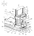
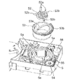
- FIG. 1 is a perspective view showing a schematic configuration of the disk device.
- the lower left side in FIG. 1 is referred to as “device front”, and the upper right side in FIG. 1 is referred to as “device rear”.
- the disk device includes two magazine stockers 1 and 1.
- the two magazine stockers 1 and 1 are provided on the bottom chassis 11 so as to face each other in the apparatus width direction Y.
- FIG. 1 the illustration of one (front side) magazine stocker 1 is omitted.
- FIG. 1 illustration of the top plate and the partition plate of the magazine stocker 1 is omitted.
- Each magazine stocker 1 stores a plurality of magazines 2.
- Each magazine 2 has a magazine tray 21 for storing a plurality of (for example, 12) disks. Between the two magazine stockers 1 and 1, there is provided a picker 3 that pulls out the magazine tray 21 from one magazine 2 selected from the plurality of magazines 2 and holds the magazine tray 21.
- the picker 3 is configured to transport the held magazine tray 21 to the vicinity of a plurality of disk drives 4 arranged at the rear of the apparatus.
- the picker 3 is integrally provided with a lifter 5 that pushes out a plurality of discs 100 from the magazine tray 21.
- the disk drive 4 is a device that records or reproduces information on the disk 100.
- the disk drive 4 is a tray type disk drive that loads a disk using a tray 4a (see FIG. 44).
- the plurality of disk drives 4 are stacked in the apparatus height direction Z, and are arranged adjacent to the magazine stockers 1 and 1 at the rear of the apparatus.
- a carrier 106 is provided between the plurality of disk drives 4 stacked adjacent to one magazine stocker 1 and the plurality of disk drives 4 stacked adjacent to the other magazine stocker 1. Yes.
- the carrier 106 holds the plurality of discs 100 pushed out by the lifter 5 in a stacked state, and above the tray 4a ejected from any disc drive 4, one disc 100 out of the held plurality of discs. And the separated disk 100 is placed on the tray 4a.
- the tray 4a is collected in the disk drive 4, and a center cone 110 of a spindle motor (not shown) is inserted into the center hole 100a of the loaded disk 100 as shown in FIG.
- the center cone 110 includes a cylindrical surface 110a that engages with the center hole 100a of the disk 100, and a conical surface 110b that gradually decreases in outer diameter from the cylindrical surface 110a toward the tip.
- the disc 100 separated by the conical surface 110b is guided through the center hole 100a, and the disc 100 is centered by the cylindrical surface 110a.
- the upper surface of the disk 100 is the upper surface of the disk, and the lower surface is the lower surface of the disk.
- a recording surface is formed on the lower surface of the disk.
- FIG. 45A the configuration of the escape portion of the disk 100 is shown in FIG. 45A, which will be described later. However, FIG. 45B, FIG.
- the electric circuit and power source 7 is provided with a control unit that controls the operation (motor, etc.) of each device such as the picker 3, the disk drive 4, and the carrier 106.
- the control unit is connected to, for example, a host computer that manages data. Based on the operator's instruction, the host computer sends a command to the control unit so as to perform operations such as writing or reading data to or from the designated magazine 2.
- the control unit controls the operation of each device such as the picker 3, the disk drive 4, and the carrier 106 in accordance with the command.
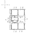
- the magazine stocker 1 is provided along a guide rail 12 that slidably guides the picker 3.
- the guide rail 12 is provided so as to extend in the apparatus depth direction X (longitudinal direction of the magazine stocker 1).
- a handle 13 is provided on the side surface of the magazine stocker 1 on the front side of the apparatus. By pulling the handle 13, the magazine stocker 1 can be moved forward of the apparatus.
- Each magazine stocker 1 includes a partition plate (not shown) formed in a lattice shape when viewed from the apparatus width direction Y.
- the magazine 2 is accommodated in each space surrounded by the partition plate.
- the magazine 2 includes a magazine tray 21 and a substantially rectangular parallelepiped case 22 that houses the magazine tray 21.
- an opening 22 a into which the magazine tray 21 can be inserted and removed is provided on the front surface (one side surface) of the case 22.
- the outer shape of the magazine tray 21 is formed in a substantially rectangular shape in plan view.
- the magazine tray 21 stores a plurality of discs 100 in a state where they are stacked in close contact with each other. Cut portions 21 a and 21 a are formed at both corner portions located on the back side of the case 22 when the magazine tray 21 is stored in the case 22. Further, when the magazine tray 21 is housed in the case 22, the entire side surface 21b located on the back side of the case 22 is formed in an arc shape including the cut portions 21a and 21a.
- the disc 100 has a center hole 100a, and an upper surface side annular rib 101a and a lower surface side annular rib 101b (the outer periphery side is not shown) are respectively formed on the inner and outer peripheral sides of the upper and lower surfaces.
- a supportable structure is formed on the inner periphery of the disk 100.
- Various structures can be adopted as the supportable structure.
- it is constituted by an escape portion 102 formed by a tapered surface 102a that gradually spreads upward on the inner peripheral portion of the upper surface of the disk 100 upward.
- the gap G to be formed is a gap (0.15 mm) formed by the annular ribs 101a and 101b and a gap (0.15 mm) formed by the tapered surface 102a ( 0.65 mm) can be added (0.8 mm).
- it is constituted by an escape portion 102 formed so that a horizontal surface 102b extends from the middle of the tapered surface 102a to the inner diameter side.
- the gap G formed with respect to the thickness T (1.2 mm) of the disk 100 is the gap formed by the annular ribs 101a and 101b, that is, the height dimension h1 (0 of the annular rib 101a).
- FIG. 45C it is comprised by the relief part 102 formed of the horizontal surface 102b and the cylindrical surface 102c.
- the specific vertical dimension is the same as that shown in FIG. 45B.
- FIGS. 45A to 45C since the centering is performed on the lower side of the disk 100, the escape portion 102 is formed on the upper side.
- FIG. 45D an annular recess 103 that is recessed toward the outer diameter side is formed on the inner peripheral surface of the disk 100.
- the recess 103 is formed at the center with respect to the thickness direction of the disk 100.
- an annular protrusion 104 that protrudes toward the inner diameter side is formed on the inner peripheral surface of the disk 100.
- the protrusion 104 is formed at the center with respect to the thickness direction of the disk 100.
- the protrusion 104 does not necessarily have to be connected in a ring shape.
- what is necessary is just to utilize the internal peripheral surface of the protrusion part 104 as a hole for centering.
- the upper surface side annular rib 101a of the lower disk 100B contacts the lower surface side annular rib 101b of the upper disk 100A.
- a gap is formed between the disks 100A and 100B.
- the clearance between the disks 100A and 100B is further widened by the escape portion. Therefore, even if the separation claw (claw portions 164Ac and 164Bc of the separator hooks 164A and 164B) described later is not so high in positioning accuracy, the separation claw can be surely entered into the gap between the discs 100A and 100B. it can. 45B, in particular, the relief portion 102 having the configuration shown in FIG. 45C is widened toward the outer diameter side while maintaining the vertical gap on the inner peripheral surface side.
- 45D and the protrusion 104 shown in FIG. 45E have the same shape on the upper and lower surfaces, which is effective for the disc 100 having the storage layers on both sides.
- the escape portion 102 is not only for avoiding interference with the separation claw when supporting the disc 100A positioned one above, but also, for example, on the inner peripheral portion of the lower surface of the disc 100 as shown in FIG. It is also possible to form a space for supporting the disc 100 itself by forming the relief portion 102 having a configuration in which the horizontal surface 103e extends to the inner diameter side from the middle of the tapered surface 103d similar to the configuration shown in FIG. 45B. It is.
- Notches 21c and 21c are formed at both corners located on the front side of the case 22 when the magazine tray 21 is stored in the case 22.
- engaging recesses 21d and 21d are formed on the inner side of the notches 21c and 21c to be engaged with a pair of hooks 35 and 35 described later.
- the magazine tray 21 is provided with a core rod 23 that is inserted into a central hole 100a provided in each of the plurality of disks 100 and restricts movement of each disk 100 in the surface direction.
- the core rod 23 prevents each disk 100 from being damaged by the movement of each disk 100 in the surface direction.
- the core rod 23 is provided with an engaging portion 23a with which a spindle head 67b of a disk chuck unit 62 described later is engaged.
- At least one hole 21e into which a lift pin 52a of the lifter 5 described later is inserted is provided.
- three holes 21e are provided at intervals of 120 degrees. Further, the three holes 21 e are provided at positions facing the non-recording / reproducing area on the inner peripheral portion of the disc 100 when the disc 100 is inserted into the core rod 23.
- the picker 3 includes a traveling base 31. As shown in FIG. 3, a carriage 31 a that slidably moves the guide rail 12 is attached to one magazine stocker 1 side of the traveling base 31. In addition, a roller 31b is attached to the other magazine stocker 1 side of the traveling base 31 as shown in FIG.
- the traveling base 31 is provided with a picker motor 31c that generates a driving force for moving the picker 3 in the apparatus depth direction X, as shown in FIG.
- a reduction gear 31d meshes with the motor gear 31i press-fitted into the drive shaft of the picker motor 31c.
- the reduction gear 31d meshes with the pinion gear 31e.
- the pinion gear 31e meshes with the rack 14 provided so as to extend in the apparatus depth direction X adjacent to the guide rail 12.
- a stepping motor is used as the picker motor 31c.
- the picker 3 By giving a predetermined pulse to the picker motor 31c, the picker 3 can be moved in front of the predetermined magazine 2.
- a picker base 31h made of resin is attached to the traveling base 31 made of sheet metal.
- the picker base 31h is provided with a turntable 32 that is rotatable about a rotation shaft 32a extending in the apparatus height direction Z.
- the picker base 31h is provided with a turntable motor 31f that generates a driving force for rotating the turntable 32.
- a reduction gear 31g is meshed with the motor gear 31j press-fitted into the drive shaft of the turntable motor 31f.
- the reduction gear 31g meshes with a turntable gear 32b provided on the outer periphery of the turntable 32.
- the turntable 32 is provided with a pair of elevating rails 33, 33 extending in the apparatus height direction Z and facing each other.
- a lifting platform 34 is provided between the pair of lifting rails 33, 33.
- the rotary table 32 is provided with a lift motor 32c that generates a driving force for moving the lift 34 up and down.
- a relay gear 32d is engaged with the motor gear 32k press-fitted into the drive shaft of the elevator motor 32c.
- the connecting shaft gear 32e meshes with the relay gear 32d.
- a connecting shaft 32f passes through the center of the connecting shaft gear 32e.
- Worms 32g and 32g are fixed to both ends of the connecting shaft 32f.
- Each worm 32g is engaged with the relay gear 32h.
- Each relay gear 32h meshes with the lead screw gear 32i.
- Each lead screw gear 32i is fixed to a lead screw 32j.
- Each lead screw 32j is provided so as to extend in the apparatus height direction Z along the elevating rail 33.
- a nut 34a provided on the lifting platform 34 is screwed into each lead screw 32j.
- the driving force of the lifting / lowering table motor 32c When the lifting / lowering table motor 32c is driven, the driving force of the lifting / lowering table motor 32c generates the lead screw 32j via the motor gear 32k, the relay gear 32d, the connecting shaft gear 32e, the connecting shaft 32f, the worm 32g, the relay gear 32h, and the lead screw gear 32i. And the lead screw 32j rotates. As a result, the lifting platform 34 moves up and down in the apparatus height direction Z along the pair of lifting rails 33, 33.
- the lifting platform 34 includes a pair of hooks 35, 35 that can be engaged with the engaging recess 21 d of the magazine tray 21, and a mechanism that opens and closes the pair of hooks 35, 35. And a chuck 36 to be moved to.
- the lift table 34 is provided with a chuck motor 34b.
- the reduction gear 34c meshes with the motor gear 34f press-fitted into the drive shaft of the chuck motor 34b.
- the reduction gear 34c meshes with the lead screw gear 34d.
- the lead screw gear 34d is fixed to the lead screw 34e.
- the lead screw 34e is provided so as to extend in a direction orthogonal to a straight line connecting the pair of lifting rails 33, 33.
- a nut 36a fixed to the chuck 36 is screwed into the lead screw 34e.
- the driving force of the chuck motor 34b is transmitted to the nut 36a via the motor gear 34f, the reduction gear 34c, the lead screw gear 34d, and the lead screw 34e, and the chuck 36 moves along the lead screw 34e. Moving.
- the chuck 36 is configured so that the distance between the pair of hooks 35 and 35 can be adjusted. As the chuck 36 reduces the distance between the pair of hooks 35, 35, the pair of hooks 35, 35 can be engaged with the engagement recesses 21 d, 21 d of the magazine tray 21. On the other hand, when the chuck 36 widens the distance between the pair of hooks 35, 35, the engagement state between the pair of hooks 35, 35 and the engagement recesses 21 d, 21 d of the magazine tray 21 can be released.
- the pair of elevating rails 33 is attached to both side surfaces of the U-shaped angle 37.
- the upper ends of the pair of lead screws 32j are rotatably attached to the upper surface of the angle 37.
- the picker motor 31c, the rotary table motor 31f, the lift table motor 32c, and the chuck motor 34b are connected to a control unit of the electric circuit and the power source 7 via an FFC (flexible flat cable) 114 (see FIG. 1).
- the drive is controlled by.
- FIG. 6 to 12 show how the picker 3 pulls out the magazine tray 21 from the case 22.
- the traveling base 31 travels in the apparatus depth direction X and the lifting platform 34 moves up and down in the apparatus height direction Z along the pair of lifting rails 33, as shown in FIG.
- the picker 3 is moved to the front of the selected one magazine 2. Further, as shown in FIG. 7, the turntable 32 is rotated so that the chuck 36 faces the front of the magazine 2.
- the chuck 36 advances toward the magazine tray 21, and the pair of hooks 35, 35 are engaged with the engaging recesses 21d, 21d of the magazine tray 21, as shown in FIG. .
- the magazine 36 is pulled out from the case 22 when the chuck 36 is retracted from the case 22.
- the turntable 32 rotates the rotation shaft 32a. Is rotated clockwise about the center.
- the distance L1 from the apex 21f of the side surface 21b of the magazine tray 21 (the position farthest from the rotation shaft 32a) to the rotation shaft 32a is the front end 22b of the side surface of the case 22.
- the rotation table 32 becomes smaller than the distance L2 from the rotary shaft 32a, the rotary base 32 is rotated clockwise about the rotary shaft 32a.
- the magazine tray 21 rotates about the rotation shaft 32a as shown in FIGS.
- the magazine tray 21 is completely pulled out from the case 22 as shown in FIG.
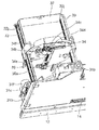
- the magazine tray 21 pulled out from the case 22 is located in the vicinity of the plurality of disk drives 4 as shown in FIGS. 13 and 14, as the traveling base 31 of the picker 3 travels backward. To be transported. Thereafter, as shown in FIG. 15, the chuck 36 of the picker 3 moves forward, and the magazine tray 21 is placed at a predetermined position on the magazine tray guide 51 above the lifter 5. 14 and 15, the illustration of the front disk drive 4 is omitted.
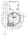
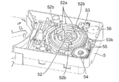
- FIG. 16 is an exploded perspective view showing a state where the magazine tray guide 51 of the lifter 5 is removed, and FIG. 17 is an assembled perspective view thereof.
- the lifter 5 includes a lift plate 52, a rotating cam 53, a drive gear 54, a relay gear 55, and a lifter motor 56.
- the elevating plate 52 includes elevating pins 52a and cam pins 52b, which are examples of rod-shaped members.
- three elevating pins 52a and three cam pins 52b are provided at intervals of 120 degrees.
- the three lifting pins 52a are provided on the magazine tray 21 as shown in FIG. 2B. It is provided at a position that coincides with the hole 21e.
- the magazine tray guide 51 is provided with three holes 51a at positions corresponding to the three lifting pins 52a.
- the three cam pins 52 b are engaged with three slits 5 a provided in the main body of the lifter 5. Each slit 5a is provided so as to extend in the apparatus height direction Z.
- Three cam grooves 53a having slopes on which the tip portions of the three cam pins 52b slide are provided on the inner peripheral surface of the rotating cam 53.
- a cam gear 53 b is provided on the outer peripheral surface of the rotating cam 53.
- the cam gear 53b meshes with the drive gear 54.
- the drive gear 54 meshes with the relay gear 55.
- the relay gear 55 meshes with a motor gear (not shown) press-fitted into the drive shaft of the lifter motor 56.
- the lifting plate 52 is lifted and lowered in the apparatus height direction Z.
- the lifter motor 56 is connected to the control unit of the electric circuit and the power source 7 via the FFC 14 (see FIG. 1), and the drive is controlled by the control unit.
- the elevating plate 52 moves up, the three elevating pins 52 a enter the magazine tray 21 through the three holes 51 a of the magazine tray guide 51 and the three holes 21 e of the magazine tray 21.
- the plurality of discs 100 are pushed out from the magazine tray 21.
- the plurality of disks 100 pushed out by the three lifting pins 52 a are held by the carrier 106.
- the carrier 106 is provided in a housing 8 that houses a plurality of (for example, 12) disk drives 4.
- the carrier 106 holds a plurality of discs pushed out by the lifter 5, separates one disc from the held plurality of discs above the tray 4 a ejected from any disc drive 4, and The separated disk is configured to be placed on the tray 4a.
- the carrier 106 includes a moving base 161 that moves in the apparatus height direction Z, and a disc chuck unit 162 provided on the moving base 161.
- the moving base 161 includes a bush 161a connected to the ball screw 63 (see FIG. 18) and a guide bearing 161b connected to the guide shaft 64 (see FIG. 18).
- the carrier motor 65 (see FIG. 18) is driven and the ball screw 63 rotates, the moving base 161 moves in the apparatus height direction Z while being guided by the ball screw 63 and the guide shaft 64.
- a gear plate 163 provided with rotating shafts or rotating bearings of various gears to be described later is attached.
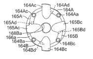
- the disk chuck unit 162 is configured to hold a plurality of disks 100 pushed out by the lifter 5 and separate the held disks 100 one by one. Specifically, as shown in FIGS. 23 and 24, the disc chuck unit 162 includes separator hooks 164A and 164B, bottom hooks 165A and 165B, a spindle unit 166, and a camshaft unit 167.
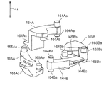
- FIG. 25 is an enlarged perspective view of the separator hooks 164A and 164B and the bottom hooks 165A and 165B.
- Each of the hooks 164A to 165B is formed in a substantially lever shape and extends in the direction intersecting the apparatus height direction Z with the rotation shafts 164Aa to 165Ba and the drive pins 164Ab to 165Bb extending in the apparatus height direction Z.
- Projecting claw portions 164Ac to 165Bc are provided.
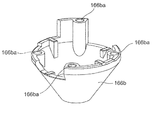
- a concave portion 100b is provided in the inner peripheral portion of the disk 100.
- the concave portion 100b is formed in a shape obtained by cutting the upper corner portion of the inner peripheral portion of the disc 100 so as to have a flat surface 100ba and an inclined surface 100bb.
- the lower surfaces of the claw portions 164Ac and 164Bc of the separator hooks 164A and 164B are formed to have a slope so that the thickness increases downward from the outer peripheral side toward the inner peripheral side.
- the upper surfaces of the claw portions 164Ac to 165Bc are formed so as to be orthogonal to the apparatus height direction Z.
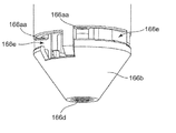
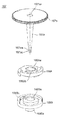
- the spindle unit 166 includes a substantially cylindrical spindle shaft 166a, a substantially truncated cone shaped spindle head 166b provided below the spindle shaft 166a, and an upper end of the spindle shaft 166a. And a provided flange 166c.
- the spindle unit 166 moves integrally with the moving base 161 by attaching the flange 166c directly or indirectly to the moving base 161.
- the diameter of the spindle shaft 166a is almost the same as or slightly smaller than the diameter of the central hole 100a of the disk 100. Therefore, the disk 100 is positioned in the radial direction with respect to the spindle shaft 166a in a state where the spindle shaft 166a is inserted into the center hole 100a of the disk 100.
- the disc 100 has an escape portion 103 formed on the inner periphery thereof, and the range of the center hole 100a guided by the spindle shaft 166a is about half of the conventional one. Therefore, even if the diameter of the spindle shaft 166a is substantially the same as the diameter of the center hole 100a of the disc 100, the spindle shaft 166a can be inserted without difficulty.
- the spindle head 166b is fixed to the lower end portion of the spindle shaft 166a with screws 166d as shown in FIG.
- Four openings 166e are formed between the spindle head 166b and the spindle shaft 166a.
- the claw portions 164Ac to 165Bc of the hooks 164A to 165B are configured to be capable of moving forward and backward through the openings 166e.
- the spindle head 166b is provided with four rotation shaft holes 166ba as shown in FIG. Further, as shown in FIG. 26, the spindle shaft 166a is provided with a rotation shaft hole 166aa at a position facing the rotation shaft hole 166ba.
- the hooks 164A to 165B are rotatably held by inserting the rotation shafts 164Aa to 165Ba into the corresponding rotation shaft holes 166aa and 166ba.
- the hooks 164A to 165B are positioned so that the upper surfaces of the claw portions 164Ac and 164Bc of the separator hooks 164A and 164B are approximately one disk higher than the upper surfaces of the claw portions 165Ac and 165Bc of the bottom hooks 165A and 165B. Retained respectively. Further, the separator hook 164A and the separator hook 164B are held at positions that are 180 degrees out of phase in the circumferential direction of the spindle unit 166, and the bottom hook 165A and the bottom hook 165B are 180 degrees out of phase in the circumferential direction of the spindle unit 166. It is held at a shifted position.
- the claw portions 164Ac and 164Bc of the separator hooks 164A and 164B constitute a separation claw that can support the inner peripheral portion of the lower surface of the disk 100 one level above the bottom.
- the claw portions 165Ac and 165Bc of the bottom hooks 165A and 165B constitute a support claw capable of supporting the inner peripheral portion of the lower surface of the disk 100 located at the lowermost portion.
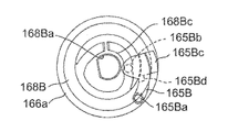
- the camshaft unit 167 includes a substantially cylindrical camshaft 167a, a cam gear 167b provided at the upper end portion of the camshaft 167a, and a cam plate 168A provided at the lower end portion of the camshaft 167a. 168B.
- Rotating shaft hole 167ba is provided at the center of cam gear 167b.
- the rotation shaft 163a provided on the gear plate 163 is inserted into the rotation shaft hole 167ba.
- the cam gear 167b meshes with the relay gear 170 as shown in FIG.
- the relay gear 170 is composed of, for example, two gears, and a rotation shaft hole 170a is provided at each central portion.
- a rotation shaft 163b provided on the gear plate 163 is inserted into the rotation shaft hole 170a.
- the relay gear 170 meshes with a motor gear 171 a that is press-fitted into a drive shaft of a disc chuck motor 171 provided on the moving base 161.
- the driving force of the disc chuck motor 171 is transmitted to the camshaft 167a via the motor gear 171a, the relay gear 170, and the cam gear 167b, and the camshaft 167a rotates about the rotation shaft 163a. .
- an engaging portion 167aa that engages with the cam plate 168A and an engaging portion 167ab that engages with the cam plate 168B are provided at the lower end of the cam shaft 167a.
- the engaging portions 167aa and 167ab are each formed in a D-shaped cross section.
- a D-shaped rotation shaft hole 168Aa is provided at the center of the cam plate 168A.
- the cam plate 168A is configured to be rotatable integrally with the camshaft 167a by engaging the engaging portion 167aa of the camshaft 167a with the rotating shaft hole 168Aa.
- a D-shaped rotation shaft hole 168Ba is provided at the center of the upper surface of the cam plate 168B.
- the cam plate 168B is configured to be rotatable integrally with the camshaft 167a by engaging the engaging portion 167ab of the camshaft 167a with the rotating shaft hole 168Ba.
- Rotating shaft 168Bb is provided at the center of the lower surface of cam plate 168B.
- the rotation shaft 168Bb is inserted into a rotation bearing 166ab provided at the lower end portion of the spindle shaft 166a as shown in FIG.
- the rotation shaft 168 ⁇ / b> Bb is positioned coaxially with the rotation shaft 163 a of the gear plate 163.
- the upper surface of the cam plate 168A is provided with a cam groove 168Ab (see FIG. 28) in which the drive pin 164Ab of the separator hook 164A slides when the cam shaft 167a rotates.
- 30A to 30D show how the drive pin 164Ab of the separator hook 164A slides in the cam groove 168Ab.
- the lower surface of the cam plate 168A is provided with a cam groove 168Ac (see FIG. 29) through which the drive pin 164Bb of the separator hook 164B slides when the cam shaft 167a rotates.
- FIGS. 31A to 31D show how the drive pin 164Bb of the separator hook 164B slides in the cam groove 168Ac.
- the cam groove 168Ac has a mirror-symmetrical shape with the cam groove 168Ab, and is provided at a position shifted in phase by 180 degrees in the circumferential direction of the spindle unit 166.
- the upper surface of the cam plate 168B is provided with a cam groove 168Bc (see FIG. 28) through which the drive pin 165Bb of the bottom hook 165B slides when the cam shaft 167a rotates.
- 32A to 32D show how the drive pin 165Bb of the bottom hook 165B slides in the cam groove 168Bc.
- the lower surface of the cam plate 168B is provided with a cam groove 168Bd (see FIG. 29) in which the drive pin 165Ab of the bottom hook 165A slides when the cam shaft 167a rotates.
- 33A to 33D show how the drive pin 165Ab of the bottom hook 165A slides in the cam groove 168Bd.
- the cam groove 168Bd has a mirror-symmetrical shape with the cam groove 168Bc, and is provided at a position shifted in phase by 180 degrees in the circumferential direction of the spindle unit 166.
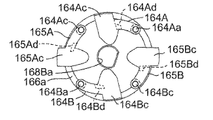
- 34A to 34D are diagrams showing the positional relationship between the camshaft 167a and the four hooks 164A to 165B.
- the separator hook 164A and the separator hook 164B are arranged such that the claw portions 164Ac and 164Bc are positioned inside the spindle shaft 166a (see FIGS. 34A and 34B) and the outside of the spindle shaft 166a as the cam shaft 167a rotates. (See FIG. 34C) and a position further outside the spindle shaft 166a (see FIG. 34D).
- the separator hooks 164A and 164B are provided with stoppers 164Ad and 164Bd in order to restrict the rotation range.
- the position shown in FIG. 34A where all the hooks 164A to 165B are located inside the spindle shaft 166a is referred to as a storage position.
- the position shown in FIG. 34B where only the bottom hooks 165A and 165B are located outside the spindle shaft 166a is referred to as a support position.
- the position shown in FIG. 34C where all the hooks 164A to 165B are located outside the spindle shaft 166a is referred to as a switching position.
- the position shown in FIG. 34D where the separator hooks 164A, 164B are located further outside the spindle shaft 166a and the bottom hooks 165A, 165B are located inside the spindle shaft 166a is referred to as a separation position.
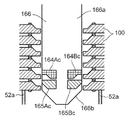
- the operation of the carrier 106 separating one disk from a plurality of disks and placing the separated disk on the tray 4a of the disk drive 4 will be described with reference to FIGS. 35 to 43, the claw portions 164Ac and 164Ad of the separator hooks 164A and 164B and the claw portions 165Ac and 165Bc of the bottom hooks 165A and 165B are illustrated on the same cross section for convenience of explanation.
- the description starts from a state in which the elevating pins 52a push out the plurality of discs 100 from the magazine tray 21.
- each of the hooks 164A to 165B is located at the storage position (see FIG. 34A).
- the moving base 161 is raised, and the upper surfaces of the claw portions 165Ac and 165Bc of the bottom hooks 165A and 165B come into contact with the inner peripheral portion of the lowermost disc 100 to support all the discs 100.
- the engagement between the spindle head 166b and the engaging portion 23a (see FIG. 2B) of the core rod 23 is released.
- the claw portions 164Ac, 164Bc of the separator hooks 164A, 164B are gaps formed between the lowermost disc 100B and the disc 100A one above it, that is, the concave portion 100b of the lowermost disc 100B which is an escape portion. Is positioned so as to be insertable.
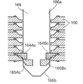
- the disc chuck motor 171 (see FIG. 21) is further driven, and the cam shaft 167a further rotates in the forward direction.
- the hooks 164A to 165B move from the support position (see FIG. 34B) to the switching position (see FIG. 34C).
- the claw portions 164Ac and 164Bc of the separator hooks 164A and 164B are inserted into the gap between the lowermost disc 100B and the disc 100A positioned one above. As described above, this gap is widened by the concave portion 100b (relief portion) formed in the lowermost disk 100.
- the claws 164Ac and 164Bc can surely enter the recesses 100b. Can do.
- the picker 3 moves to the front of the apparatus, and the magazine tray 21 is withdrawn from the vicinity of the disk drive 4. Thereafter, the tray 4a of the disk drive 4 is discharged.
- the moving base 161 is lowered so that the plurality of disks 100 held by the spindle unit 166 are positioned above (for example, directly above) the tray 4a.
- the disc chuck motor 171 is further driven, and the camshaft 167a further rotates in the forward direction.
- the hooks 164A to 165B move from the switching position (see FIG. 34C) to the separation position (see FIG. 34D), and the claw portions 165Ac and 165Bc of the bottom hooks 165A and 165B are moved to the spindle as shown in FIG. It moves to a position inside the shaft 166a.
- the lowermost disk 100 falls by its own weight and is placed on the tray 4a.
- the separator hooks 164A and 164B protrude further outward from the spindle shaft 166a, and the slopes formed on the lower surfaces of the claw portions 164Ac and 164Bc of the separator hooks 164A and 164B press the lowermost disc 100 downward, It functions to assist the disc 100 falling by its own weight. Further, the upper surfaces of the claw portions 164Ac and 164Bc of the separator hooks 164A and 164B are in contact with the inner peripheral portion of the lowermost disc 100 of the remaining discs to support the remaining discs 100.
- the moving base 161 of the lowermost disc 100 placed on the tray 4a is raised so that the spindle unit 166 and the tray 4a do not come into contact with each other. Thereafter, the tray 4 a is carried into the disk drive 4. Thereafter or simultaneously with this, the tray 4a of the disk drive 4 facing the disk drive is ejected (not shown).
- the disc chuck motor 171 is reversely driven, and the camshaft 167a rotates in the reverse direction.
- the hooks 164A to 165B move from the separation position (see FIG. 34D) to the switching position (see FIG. 34C), and the claw portions 165Ac and 165Bc of the bottom hooks 165A and 165B are moved to the spindle as shown in FIG. It moves to a position outside the shaft 166a.
- the disc chuck motor 171 is further reversely driven, and the camshaft 167a further rotates in the reverse direction.
- the hooks 164A to 165B move from the switching position (see FIG. 34C) to the support position (see FIG. 34B).
- the claws 164Ac and 164Bc of the separators 164A and 164B Move to a position inside 166a.
- the remaining disk 100 supported by the upper surfaces of the claw portions 164Ac and 164Bc of the separator hooks 164A and 164B falls due to its own weight and is supported by the upper surfaces of the claw portions 165Ac and 165Bc of the bottom hooks 165A and 165B.
- the disc chuck motor 171 (see FIG. 21) is driven, and the camshaft 167a rotates in the forward direction.
- the hooks 164A to 165B move from the support position (see FIG. 34B) to the switching position (see FIG. 34C), and as shown in FIG. 39, the claws 164Ac and 164Bc of the separator hooks 164A and 164B It is inserted into the recess 100b of the lower disk 100.
- the moving base 161 is lowered so that the plurality of discs 100 held by the spindle unit 166 are positioned above (for example, immediately above) the ejected tray 4a.
- the disc chuck motor 171 is further driven, and the camshaft 167a further rotates in the forward direction.
- the hooks 164A to 165B move from the switching position (see FIG. 34C) to the separation position (see FIG. 34D), and the claw portions 165Ac and 165Bc of the bottom hooks 165A and 165B are moved to the spindle as shown in FIG. It moves to a position inside the shaft 166a.
- FIG. 34C switching position
- FIG. 34D separation position
- the lowermost disk 100 falls by its own weight and is placed on the tray 4a.
- the separator hooks 164A and 164B protrude further outward from the spindle shaft 166a, and the slope formed on the lower surface of the claw portions 164Ac and 164Bc of the separator hooks 164A and 164B causes the lowermost disk 100 to face downward. Pressing and functioning to assist the disc 100 falling with its own weight.
- the upper surfaces of the claw portions 164Ac and 164Bc of the separator hooks 164A and 164B are in contact with the inner peripheral portion of the lowermost disk among the remaining disks to support the remaining disk 100.
- the moving base 161 When the lowermost disk 100 is placed on the tray 4a, the moving base 161 is raised so that the spindle unit 166 and the tray 4a do not come into contact with each other. Thereafter, the tray 4 a is carried into the disk drive 4. Thereby, the loading operation to the lowermost (first stage) disk drive 4 is completed. This loading operation is repeated after the second stage.
- the disks 100 are loaded into all the disk drives 4 and can be recorded or reproduced on the disks 100 of the respective disk drives 4.
- the tray 4a of the uppermost disk drive 4 is discharged.
- the moving base 161 is lowered, and the spindle unit 166 is inserted into the center hole 100a of the disk 100 on the tray 4a.
- each of the hooks 164A to 165B is in the storage position (see FIG. 34A).
- the moving base 161 is raised, and the upper surfaces of the claw portions 165Ac and 165Bc of the bottom hooks 165A and 165B come into contact with the inner peripheral portion of the disc 100 to hold the disc 100. Thereby, the disk 100 on the tray 4a is collected.
- the tray 4a from which the disc 100 has been collected is carried into the disc drive 4. Thereafter or simultaneously with this, the tray 4a of the disk drive 4 facing the disk drive 4 is discharged.
- the moving base 161 is lowered so that the disk held by the spindle unit 166 is positioned above (for example, directly above) the disk 100 on the ejected tray 4a.
- the disc chuck motor 171 (see FIG. 21) is reversely driven, and the camshaft 167a rotates in the reverse direction.
- the hooks 164A to 165B move from the support position (see FIG. 34B) to the storage position (see FIG. 34A).
- the disk 100 held by the spindle unit 166 falls by its own weight and is stacked on the disk 100 on the ejected tray 4a.
- the moving base 161 is lowered, and the spindle unit 166 is inserted into the center holes 100a of the two discs 100 on the ejected tray 4a.
- the disk chuck motor 171 (see FIG. 21) is driven, and the camshaft 167a rotates in the forward direction.
- the hooks 164A to 165B move from the storage position (see FIG. 34A) to the support position (see FIG. 34B).
- the moving base 161 is raised, and the upper surfaces of the claw portions 165Ac and 165Bc of the bottom hooks 165A and 165B come into contact with the inner peripheral portion of the lowermost disc 100 to support all the discs 100.
- the tray 4a from which the disc 100 has been collected is carried into the disc drive 4. Thereby, the disk collection operation of the uppermost (first stage) disk drive 4 is completed. This disk collecting operation is repeated until the disk 100 in the lowermost disk drive 4 is collected.
- the moving base 161 is raised. Thereafter, the picker 3 moves to the rear of the apparatus, and the magazine tray 21 is set below the spindle unit 166.
- the moving base 161 is lowered, the spindle head 166b (see FIG. 21) engages with the engaging portion 23a (see FIG. 2B) of the core rod 23, and the spindle head 166b and the core rod 23 become coaxial.
- the disc chuck motor 171 (see FIG. 21) is reversely driven, and the camshaft 167a rotates in the reverse direction.
- the hooks 164A to 165B move from the support position (see FIG. 34B) to the storage position (see FIG. 34A).
- all the disks 100 held by the spindle unit 166 fall by their own weight along the spindle head 166b and the core rod 23, and are stored in the magazine tray 21.
- the moving base 161 is raised and the engagement between the spindle head 166b and the engaging portion 23a of the core rod 23 is released.
- the magazine tray 21 storing all the discs 100 is returned to the magazine stocker 1 by the picker 3.
- the conveyance of the magazine tray 21 into the magazine stocker 1 is performed, for example, by performing an operation reverse to the operation described with reference to FIGS.
- a plurality of disks 100 are held by the carrier 106 in a stacked state, and one disk is separated from the plurality of disks above the tray a of each disk drive 4. ing.
- the time required to transport the disk 100 to each of the plurality of disk drives 4 can be greatly reduced as compared with the conventional disk device that transports the disks one by one from the magazine to the disk drive.
- the separation claw (the claw portions 164Ac and 164Bc of the separator hooks 164A and 164B) of the carrier 106 supports the disk 100B positioned on one of the lowest disks 100A of the stacked disks 100.
- a plurality of discs 100 may be ejected at a time by supporting the disc 100 at an arbitrary position.
- the disk device according to the present invention is particularly useful for a disk device having a large number of magazines because the time required to supply a disk to each of a plurality of disk drives can be suppressed.
Abstract
A disk (100) having a center hole (100a), the disk (100) being provided with a support-capable structure for making it possible to support a disk (100A) positioned one level above the lowermost part in a stacked state using separation claws (164Ac, 164Bc) protruding radially outward from the center hole (100a).
Description
本発明は、ディスク、特に、積層されたディスクのうち、最下部から1つ上に位置するディスクを支持可能とする構造を備えたディスクに関する。
The present invention relates to a disk, and more particularly, to a disk having a structure capable of supporting a disk positioned one up from the bottom of the stacked disks.
従来、この種のディスクを供給するためのディスク装置として、例えば、特許文献1(特開2011-204311号公報)に記載された装置が知られている。特許文献1のディスク装置は、1枚のディスクを収納するトレイを複数収納するマガジンと、複数のディスクドライブとを備えている。特許文献1のディスク装置は、マガジンから任意のトレイを引き出し、当該引き出されたトレイに収納された1枚のディスクを吸着パッドにより吸着保持し、任意のディスクドライブのトレイに載置するように構成されている。
Conventionally, as a disk device for supplying this type of disk, for example, an apparatus described in Patent Document 1 (Japanese Patent Laid-Open No. 2011-204311) is known. The disk device of Patent Document 1 includes a magazine that stores a plurality of trays that store one disk, and a plurality of disk drives. The disk device of Patent Document 1 is configured to pull out an arbitrary tray from a magazine, suck and hold one disk stored in the pulled-out tray by a suction pad, and place it on the tray of an arbitrary disk drive. Has been.
特許文献1のディスク装置では、1つのトレイに1枚のディスクを収納するように構成されているので、マガジンに収納されるディスクの枚数が少ない。マガジンに収納されるディスクの枚数を増加させるには、複数枚のディスクを、トレイを介すことなく直接積層して、トレイの数を減らすことが有効であると考えられる。
Since the disk device of Patent Document 1 is configured to store one disk in one tray, the number of disks stored in the magazine is small. In order to increase the number of disks stored in the magazine, it is considered effective to directly stack a plurality of disks without using a tray and reduce the number of trays.
この場合、互いに隣接するディスク同士が密着して、それらを容易に分離することができなくなる。この課題を解決する技術として、特許文献2(特開2000-117553号公報)に開示された技術がある。特許文献2には、互いに隣接する2枚のディスクの間に爪部を挿入することで、当該2枚のディスクを互いに分離し、当該分離したディスクを吸着パッドに吸着保持させる技術が開示されている。
In this case, adjacent disks are brought into close contact with each other and cannot be easily separated. As a technique for solving this problem, there is a technique disclosed in Patent Document 2 (Japanese Patent Laid-Open No. 2000-117553). Patent Document 2 discloses a technique in which a claw portion is inserted between two adjacent disks so that the two disks are separated from each other, and the separated disks are sucked and held by a suction pad. Yes.
前記ディスク装置においては、ディスク収納枚数の更なる増加が求められている。ディスク収納枚数を増加させるためには、単純には、マガジンの数を増加させればよいと考えられる。
In the disk device, there is a demand for further increase in the number of disks stored. In order to increase the number of stored discs, simply increasing the number of magazines is considered.
しかしながら、マガジンの数を増加させると、ディスクドライブから最も離れて配置されるマガジンと当該ディスクドライブとの距離は必然的に長くなり、ディスクの搬送時間が増加することになる。また、前記特許文献1のディスク装置では、ディスクを1枚ずつマガジンからディスクドライブに供給するように構成されているので、複数のディスクドライブのそれぞれにディスクを供給するには、相当な時間を要する。
However, when the number of magazines is increased, the distance between the magazine arranged farthest from the disk drive and the disk drive inevitably increases, and the time for transporting the disk increases. Further, since the disk device of Patent Document 1 is configured to supply the disks one by one from the magazine to the disk drive, it takes a considerable time to supply the disks to each of the plurality of disk drives. .
また、特許文献2の技術では、複数のディスクドライブのそれぞれにディスクを供給する時間を抑えることができない。また、積層されたディスクを分離させる場合、ディスクに形成されたリブによって得られる僅かな隙間に、取り出しアームに設けた基板分離爪を差し込む必要がある。このため、取り出しアームを上下方向に高精度に位置決めしなければならないが、そのための機構は高価なものとならざるを得ない。また、基板分離爪を薄くしなければならないが、ディスクを支持できるような強度を得るのは難しく、使用時に変形の恐れがある。
Also, with the technology of Patent Document 2, it is not possible to reduce the time for supplying a disk to each of a plurality of disk drives. Further, when separating the stacked disks, it is necessary to insert a substrate separation claw provided on the take-out arm into a slight gap obtained by ribs formed on the disks. For this reason, the take-out arm must be positioned with high accuracy in the vertical direction, but the mechanism for that purpose must be expensive. Further, although the substrate separation claw must be thinned, it is difficult to obtain a strength that can support the disk, and there is a risk of deformation during use.
そこで、積層された状態で、容易かつ適切に分離することのできるディスクを提供することを課題とする。
Therefore, an object is to provide a disc that can be easily and appropriately separated in a stacked state.
前記課題を解決するための手段として、
中心穴を有するディスクであって、
積層した状態で、任意の一のディスクから1つ上に位置するディスクを、中心穴から外径側に突出する分離爪にて支持可能とするための支持可能構造を内周部に備えたものである。 As means for solving the problems,
A disc having a central hole,
The inner circumference has a supportable structure that can support a disk positioned one above the arbitrary disk in a stacked state with a separating claw protruding from the center hole to the outer diameter side. It is.
本発明によれば、ディスクには支持可能構造を形成しているため、分離爪によってディスクを支持する際、分離爪がディスクと干渉することなく、スムーズに任意の一のディスクから1つ上に位置するディスクを支持することができる。
According to the present invention, since the disc has a supportable structure, when the disc is supported by the separation pawl, the separation pawl does not interfere with the disc and smoothly moves up from any one disc. The disk located can be supported.
ディスクは、次のような態様とすることができる。
第1の態様では、
中心穴を有するディスクであって、
積層した状態で、任意の一のディスクから1つ上に位置するディスクを、中心穴から外径側に突出する分離爪にて支持可能とするための支持可能構造を内周部に備えたものである。 The disc can be configured as follows.
In the first aspect,
A disc having a central hole,
The inner circumference has a supportable structure that can support a disk positioned one above the arbitrary disk in a stacked state with a separating claw protruding from the center hole to the outer diameter side. It is.
第1の態様によれば、ディスクの中心穴から外径側に分離爪を突出させると、支持可能構造を利用して、任意の一のディスクから1つ上に位置するディスクを無理なくスムーズに支持することができる。
According to the first aspect, when the separation claw protrudes from the center hole of the disk to the outer diameter side, the supportable structure is used to smoothly and smoothly move the disk positioned one above the arbitrary one disk. Can be supported.
第2の態様では、前記支持可能構造は、ディスクの上面内周部に形成される逃がし部で構成したものである。
In the second aspect, the supportable structure is constituted by an escape portion formed on the inner peripheral portion of the upper surface of the disk.
第3の態様では、前記支持可能構造は、ディスクの下面内周部に形成される逃がし部で構成したものである。
In the third aspect, the supportable structure is constituted by a relief portion formed on the inner peripheral portion of the lower surface of the disk.
第2及び第3の態様によれば、ディスクに逃がし部を形成しただけの簡単な構成で、分離爪にて、最下部から1つ上に位置するディスクを支持することができる。
According to the second and third aspects, the disk positioned one above the lowermost part can be supported by the separation claw with a simple configuration in which the relief part is formed on the disk.
第4の態様では、前記逃がし部は、内周側に水平面を有する構成としたものである。
In the fourth aspect, the escape portion has a horizontal plane on the inner peripheral side.
第4の態様によれば、上下方向に隣り合うディスクの間に、内周面側から外径方向に向かって間隔の広い隙間を形成することができる。したがって、分離爪の上下方向の位置精度がそれほど要求されない。また、肉厚の分離爪であっても使用することが可能である。
According to the fourth aspect, it is possible to form a wide gap between the disks adjacent in the vertical direction from the inner peripheral surface side toward the outer diameter direction. Therefore, the position accuracy of the separation claw in the vertical direction is not so required. Further, even a thick separation claw can be used.
第5の態様では、前記支持可能構造は、ディスクの内周面に形成される凹部で構成したものである。
In the fifth aspect, the supportable structure is constituted by a recess formed on the inner peripheral surface of the disk.
第5の態様によれば、凹部はディスクの内周面に形成されているため、分離爪をディスクの内周側に配置し、外径側に突出させれば、簡単に凹部に位置させてディスクを支持することができる。凹部はディスクの内周面にのみ形成されただけであるので、両面に記憶層を有するディスクであっても分離爪にて支持することができる。
According to the fifth aspect, since the concave portion is formed on the inner peripheral surface of the disc, if the separation claw is arranged on the inner peripheral side of the disc and protrudes to the outer diameter side, the concave portion can be easily positioned in the concave portion. The disc can be supported. Since the recess is only formed on the inner peripheral surface of the disk, even a disk having a memory layer on both sides can be supported by the separation claw.
第6の態様では、前記支持可能構造は、ディスクの内周面から突出する突出部で構成したものである。
In the sixth aspect, the supportable structure is constituted by a protruding portion protruding from the inner peripheral surface of the disk.
第6の態様によれば、突出部はディスクの内周面に形成されているため、分離爪を突出部よりも内側に配置し、外径側に突出させれば、簡単に突出部でディスクを支持することができる。突出部はディスクの内周面にのみ形成されただけであるので、両面に記憶層を有するディスクであっても分離爪にて支持することができる。
According to the sixth aspect, since the projecting portion is formed on the inner peripheral surface of the disk, if the separating claw is arranged on the inner side of the projecting portion and projects to the outer diameter side, the projecting portion can easily be used. Can be supported. Since the protruding portion is formed only on the inner peripheral surface of the disc, even a disc having a storage layer on both sides can be supported by the separation claw.
第7の態様では、前記支持可能構造は、ディスクの内周部の上面又は下面の少なくともいずれか一方から突出するリブで構成したものである。
In the seventh aspect, the supportable structure is constituted by a rib protruding from at least one of the upper surface and the lower surface of the inner periphery of the disk.
第6及び第7の態様によれば、分離爪を突出部又はリブの内側から外径側のディスクの内周面よりも内側に突出させることにより突出部又はリブを介してディスクを支持することができる。
According to the sixth and seventh aspects, the separation claw is supported from the inside of the protruding portion or the rib to the inside of the inner peripheral surface of the disk on the outer diameter side, thereby supporting the disc via the protruding portion or the rib. Can do.
また、ディスク装置は、次のような態様とすることができる。
第8の態様では、
複数のディスクドライブのそれぞれにディスクに供給するディスク装置であって、
前記いずれかの構成のディスクを複数枚積層した状態で保持するトレイと、
前記保持した複数枚のディスクのうち、最下部から1つ上に位置するディスクを支持可能な分離爪を有し、任意のディスクドライブから排出されたトレイの上方で、前記分離爪で最下部から1つ上に位置するディスクを支持することにより、最下部に位置する1枚のディスクを分離して前記トレイに載置するキャリアと、
を備えた構成としたものである。 Further, the disk device can be configured as follows.
In the eighth aspect,
A disk device that supplies a disk to each of a plurality of disk drives,
A tray for holding a plurality of discs having any one of the above-described structures,
A separation claw capable of supporting a disk positioned one above the bottom of the plurality of held disks is provided above the tray discharged from an arbitrary disk drive, and from the bottom with the separation claw. A carrier for separating the one disk located at the bottom and placing it on the tray by supporting the disk located one above;
It is set as the structure provided with.
第8の態様によれば、ディスクが支持可能構造を備えているので、分離爪によって最下部から1つ上に位置するディスクを簡単かつスムーズに支持することができる。そして、複数のディスクドライブのそれぞれにディスクを供給するのに要する時間を抑えることが可能となる。
According to the eighth aspect, since the disc is provided with a supportable structure, the disc positioned one level above the lowermost portion can be easily and smoothly supported by the separation claw. In addition, it is possible to reduce the time required to supply the disk to each of the plurality of disk drives.
第9の態様では、
前記キャリアは、前記ディスクの中心穴に挿入されるスピンドルユニットを備え、
前記分離爪は、前記スピンドルユニットの内側に退避する退避位置と、前記ディスクの逃がし部内に突出して、最下部から1つ上に位置するディスクの下面内周部を支持可能な突出位置とに移動可能としたものである。 In the ninth aspect,
The carrier includes a spindle unit that is inserted into a center hole of the disc,
The separation claw moves between a retracted position for retracting to the inside of the spindle unit and a projecting position that protrudes into the escape part of the disk and can support the inner peripheral part of the lower surface of the disk located one level above the lowest part. It is possible.
第9の態様によれば、ディスクが支持構造を備えているので、分離爪を退避位置から突出位置に移動させるだけで、この分離爪が積層されたディスクに干渉することなく、最下部から1つ上に位置するディスクの下面内周部を容易かつスムーズに支持させることができる。
According to the ninth aspect, since the disk has the support structure, the separation claw can be moved from the retracted position to the projecting position, and the separation claw can be separated from the lowermost part without interfering with the stacked disks. It is possible to easily and smoothly support the inner peripheral portion of the lower surface of the upper disk.
第10の態様では、前記分離爪は、前記スピンドルユニットの内側に挿入されるカムシャフトの回転動作に連動して、前記退避位置と前記突出位置とに移動可能としたものである。
In the tenth aspect, the separation pawl is movable between the retracted position and the protruding position in conjunction with the rotational operation of the camshaft inserted inside the spindle unit.
第10の態様によれば、カムシャフトを回転させるだけで、分離爪を退避位置と突出位置とに移動させることができる。
According to the tenth aspect, the separation claw can be moved between the retracted position and the protruding position only by rotating the camshaft.
第11の態様では、
前記キャリアは、
前記ディスクの中心穴に挿入されるスピンドルユニットと、
前記分離爪と、
前記最下部に位置するディスクの下面内周部を支持可能な支持爪と、
を備え、
前記第分離爪及び前記支持爪は、
前記分離爪及び前記支持爪の両方が前記スピンドルユニットの内側に退避する収納位置と、
前記支持爪のみが前記スピンドルユニットの外側に突出する支持位置と、
前記分離爪及び前記支持爪の両方が前記スピンドルユニットの外側に突出する切換位置と、
前記分離爪のみが前記スピンドルユニットの外側に突出する分離位置と、
に移動可能としたものである。 In the eleventh aspect,
The carrier is
A spindle unit inserted into the center hole of the disc;
The separation claw;
A support claw capable of supporting the inner periphery of the lower surface of the disk located at the lowermost part,
With
The first separation claw and the support claw are
A storage position in which both the separation claw and the support claw are retracted inside the spindle unit;
A support position in which only the support claw protrudes outside the spindle unit;
A switching position where both the separation claw and the support claw protrude outside the spindle unit;
A separation position where only the separation claw protrudes outside the spindle unit;
It can be moved to.
第11の態様によれば、支持位置で、支持爪によってディスクを支持した状態から、分離位置で、分離爪によって最下部から1つ上のディスクを支持し、その後、切換位置で、支持爪を退避させることにより最下部のディスクのみを分離させることができる。
According to the eleventh aspect, from the state where the disk is supported by the support claw at the support position, the disk one level higher than the lowermost part is supported by the separation claw at the separation position, and then the support claw is moved at the switching position. By retracting, only the lowermost disk can be separated.
第12の態様では、前記分離爪及び前記支持爪は、前記スピンドルユニットの内側に挿入されるカムシャフトの回転に伴って、前記収納位置、前記支持位置、前記切換位置、前記分離位置の順に移動可能としたものである。
In the twelfth aspect, the separation claw and the support claw move in the order of the storage position, the support position, the switching position, and the separation position in accordance with the rotation of the camshaft inserted inside the spindle unit. It is possible.
第12の態様によれば、カムシャフトを回転させるだけで、分離爪及び支持爪を、順次、収納位置、支持位置、切換位置、分離位置の順に移動させて、最下部に位置するディスクを確実に分離させることができる。
According to the twelfth aspect, by simply rotating the camshaft, the separation pawl and the support pawl are sequentially moved in the order of the storage position, the support position, the switching position, and the separation position, so that the disc positioned at the bottom is securely Can be separated.
第13の態様では、
前記分離爪及び前記支持爪は、
前記スピンドルユニットが前記ディスクの中心穴に挿入されるとき、前記収納位置に位置し、
前記支持爪が最下部のディスクより下方に位置するまで前記スピンドルユニットが前記中心穴に挿入されたとき、前記収納位置から前記支持位置に移動することにより、前記支持爪が前記最下部のディスクの下面内周部を支持し、
前記支持爪が最下部のディスクを支持するとき、前記切換位置に移動し、
前記支持爪が最下部のディスクを支持した状態で前記トレイの上方に搬送されたとき、前記切換位置から前記分離位置に移動するようにしたものである。 In the thirteenth aspect,
The separation claw and the support claw are
When the spindle unit is inserted into the center hole of the disk, it is located at the storage position,
When the spindle unit is inserted into the center hole until the support claw is positioned below the lowermost disk, the support claw is moved from the storage position to the support position, so that the support claw is moved to the lowermost disk. Support the inner periphery of the lower surface,
When the support claw supports the lowermost disk, it moves to the switching position,
When the support claw is transported above the tray while supporting the lowermost disk, the support claw is moved from the switching position to the separation position.
第13の態様によれば、スピンドルユニットの昇降位置に応じて、ディスクに対して適切に分離爪及び支持爪を突出又は退避させることができ、確実に最下部に位置するディスクのみを分離することが可能である。
According to the thirteenth aspect, the separation claw and the support claw can be appropriately protruded or retreated with respect to the disk in accordance with the raising / lowering position of the spindle unit, and only the disk positioned at the lowermost part is reliably separated. Is possible.
第14の態様では、前記分離爪は、外周側から内周側に向かうに従い下方向に厚さが厚くなるように形成される傾斜面を有し、前記分離位置に位置するとき、前記切換位置に位置するときよりも前記スピンドルユニットの外側に突出して、前記傾斜面により前記最下部に位置するディスクを下方に押圧するものである。
In the fourteenth aspect, the separation claw has an inclined surface formed so as to increase in thickness downward from the outer peripheral side toward the inner peripheral side, and when the separation claw is positioned at the separation position, It protrudes to the outside of the spindle unit as compared to when it is positioned at the position, and the disk positioned at the lowermost portion is pressed downward by the inclined surface.
第14の態様によれば、分離爪で最下部から1つ上に位置するディスクの下面内周部を支持した状態から、この分離爪を外側に突出させるだけで、押圧面により最下部のディスクを押圧して容易かつ確実に分離させることができる。
According to the fourteenth aspect, from the state where the inner surface of the lower surface of the disk located one level above the lowermost part is supported by the separation pawl, the lowermost disk can be pushed by the pressing surface only by projecting the separation pawl outward. Can be separated easily and reliably.
以下、本発明の実施形態について、図面を参照しながら説明する。なお、以下の全ての図において、同一又は相当部分には同一符号を付し、重複する説明は省略する。
Hereinafter, embodiments of the present invention will be described with reference to the drawings. In all of the following drawings, the same or corresponding parts are denoted by the same reference numerals, and redundant description is omitted.
図1は、ディスク装置の概略構成を示す斜視図である。なお、以下の説明では、図1の左下側を「装置前方」といい、図1の右上側を「装置後方」という。
FIG. 1 is a perspective view showing a schematic configuration of the disk device. In the following description, the lower left side in FIG. 1 is referred to as “device front”, and the upper right side in FIG. 1 is referred to as “device rear”.
まず、図1を用いてディスク装置の全体構成について説明する。
ディスク装置は、2つのマガジンストッカー1,1を備えている。2つのマガジンストッカー1,1は、底シャーシ11上において、装置幅方向Yに互いに対向するように設けられている。なお、図1では、一方(手前側)のマガジンストッカー1の図示を省略している。また、図1では、マガジンストッカー1の天板及び仕切板の図示を省略している。 First, the overall configuration of the disk device will be described with reference to FIG.
The disk device includes two magazine stockers 1 and 1. The two magazine stockers 1 and 1 are provided on the bottom chassis 11 so as to face each other in the apparatus width direction Y. In FIG. 1, the illustration of one (front side) magazine stocker 1 is omitted. Moreover, in FIG. 1, illustration of the top plate and the partition plate of the magazine stocker 1 is omitted.
ディスク装置は、2つのマガジンストッカー1,1を備えている。2つのマガジンストッカー1,1は、底シャーシ11上において、装置幅方向Yに互いに対向するように設けられている。なお、図1では、一方(手前側)のマガジンストッカー1の図示を省略している。また、図1では、マガジンストッカー1の天板及び仕切板の図示を省略している。 First, the overall configuration of the disk device will be described with reference to FIG.
The disk device includes two
各マガジンストッカー1には、複数のマガジン2が収納されている。各マガジン2は、複数枚(例えば、12枚)のディスクを収納するマガジントレイ21を有している。2つのマガジンストッカー1,1の間には、複数のマガジン2の中から選択された1つのマガジン2からマガジントレイ21を引き出し、当該マガジントレイ21を保持するピッカー3が設けられている。
Each magazine stocker 1 stores a plurality of magazines 2. Each magazine 2 has a magazine tray 21 for storing a plurality of (for example, 12) disks. Between the two magazine stockers 1 and 1, there is provided a picker 3 that pulls out the magazine tray 21 from one magazine 2 selected from the plurality of magazines 2 and holds the magazine tray 21.
ピッカー3は、当該保持したマガジントレイ21を、装置後方に配置された複数のディスクドライブ4の近傍まで搬送するように構成されている。ピッカー3には、マガジントレイ21から複数枚のディスク100を押し出すリフター5が一体的に設けられている。
The picker 3 is configured to transport the held magazine tray 21 to the vicinity of a plurality of disk drives 4 arranged at the rear of the apparatus. The picker 3 is integrally provided with a lifter 5 that pushes out a plurality of discs 100 from the magazine tray 21.
ディスクドライブ4は、ディスク100に対して情報の記録又は再生を行う装置である。また、ディスクドライブ4は、トレイ4a(図44参照)を用いてディスクをローディングするトレイ方式のディスクドライブである。複数のディスクドライブ4は、装置高さ方向Zに積層され、装置後方において各マガジンストッカー1,1に隣接して配置されている。一方のマガジンストッカー1に隣接して積層配置された複数のディスクドライブ4と、他方のマガジンストッカー1に隣接して積層配置された複数のディスクドライブ4との間には、キャリア106が設けられている。
The disk drive 4 is a device that records or reproduces information on the disk 100. The disk drive 4 is a tray type disk drive that loads a disk using a tray 4a (see FIG. 44). The plurality of disk drives 4 are stacked in the apparatus height direction Z, and are arranged adjacent to the magazine stockers 1 and 1 at the rear of the apparatus. A carrier 106 is provided between the plurality of disk drives 4 stacked adjacent to one magazine stocker 1 and the plurality of disk drives 4 stacked adjacent to the other magazine stocker 1. Yes.
キャリア106は、リフター5により押し出された複数枚のディスク100を積層状態で保持し、任意のディスクドライブ4から排出されたトレイ4aの上方で、前記保持した複数枚のディスクから1枚のディスク100を分離し、当該分離したディスク100を前記トレイ4aに載置するように構成されている。
The carrier 106 holds the plurality of discs 100 pushed out by the lifter 5 in a stacked state, and above the tray 4a ejected from any disc drive 4, one disc 100 out of the held plurality of discs. And the separated disk 100 is placed on the tray 4a.
トレイ4aはディスクドライブ4内に回収され、載置されたディスク100の中心穴100aには、図44に示すように、スピンドルモータ(図示せず)のセンターコーン110が挿通される。センターコーン110は、ディスク100の中心穴100aに係合する円筒面110aと、そこから先端に向かって徐々に外径寸法が小さくなる円錐面110bとを備える。円錐面110bによって分離したディスク100が中心穴100aを案内され、円筒面110aによってディスク100の芯出が行われる。なお、図44において、ディスク100の上側に位置する面がディスク上面、下側に位置する面がディスク下面であり、このディスク下面に記録面が形成されている。また、図44では、ディスク100の逃がし部の構成を後述する図45Aとしたが、図45B、図45C等であっても同様に対応することができる。
The tray 4a is collected in the disk drive 4, and a center cone 110 of a spindle motor (not shown) is inserted into the center hole 100a of the loaded disk 100 as shown in FIG. The center cone 110 includes a cylindrical surface 110a that engages with the center hole 100a of the disk 100, and a conical surface 110b that gradually decreases in outer diameter from the cylindrical surface 110a toward the tip. The disc 100 separated by the conical surface 110b is guided through the center hole 100a, and the disc 100 is centered by the cylindrical surface 110a. In FIG. 44, the upper surface of the disk 100 is the upper surface of the disk, and the lower surface is the lower surface of the disk. A recording surface is formed on the lower surface of the disk. In FIG. 44, the configuration of the escape portion of the disk 100 is shown in FIG. 45A, which will be described later. However, FIG. 45B, FIG.
キャリア106及び複数のディスクドライブ4より更に装置後方には、電気回路及び電源7が設けられている。電気回路及び電源7には、ピッカー3、ディスクドライブ4、キャリア106などの各装置の動作(モータ等)を制御する制御部が設けられている。当該制御部は、例えば、データを管理するホストコンピュータに接続されている。ホストコンピュータは、オペレータの指示に基づき、指定のマガジン2へのデータの書き込み又は読み出し等の動作を行うように制御部に指令を送る。制御部は、当該指令に従い、ピッカー3、ディスクドライブ4、キャリア106などの各装置の動作を制御する。
Further behind the carrier 106 and the plurality of disk drives 4, an electric circuit and a power source 7 are provided. The electric circuit and power source 7 is provided with a control unit that controls the operation (motor, etc.) of each device such as the picker 3, the disk drive 4, and the carrier 106. The control unit is connected to, for example, a host computer that manages data. Based on the operator's instruction, the host computer sends a command to the control unit so as to perform operations such as writing or reading data to or from the designated magazine 2. The control unit controls the operation of each device such as the picker 3, the disk drive 4, and the carrier 106 in accordance with the command.
次に、前述した各装置及び各部品の構成についてより詳しく説明する。
Next, the configuration of each device and each component described above will be described in more detail.
マガジンストッカー1は、ピッカー3を摺動自在にガイドするガイドレール12に沿って設けられている。ガイドレール12は、装置奥行き方向Xに(マガジンストッカー1の長手方向)に延在するように設けられている。マガジンストッカー1の装置前方側の側面には、把手13が設けられている。把手13を引くことにより、マガジンストッカー1を装置前方に移動させることができる。各マガジンストッカー1は、装置幅方向Yから見て格子状に形成された仕切板(図示せず)を備えている。当該仕切板に囲まれたそれぞれの空間にマガジン2が収納されている。
The magazine stocker 1 is provided along a guide rail 12 that slidably guides the picker 3. The guide rail 12 is provided so as to extend in the apparatus depth direction X (longitudinal direction of the magazine stocker 1). A handle 13 is provided on the side surface of the magazine stocker 1 on the front side of the apparatus. By pulling the handle 13, the magazine stocker 1 can be moved forward of the apparatus. Each magazine stocker 1 includes a partition plate (not shown) formed in a lattice shape when viewed from the apparatus width direction Y. The magazine 2 is accommodated in each space surrounded by the partition plate.
マガジン2は、図2Aに示すように、マガジントレイ21と、マガジントレイ21を収納する略直方体形状のケース22とを備えている。ケース22の前面(一側面)には、図2Bに示すように、マガジントレイ21を挿抜可能な開口部22aが設けられている。
As shown in FIG. 2A, the magazine 2 includes a magazine tray 21 and a substantially rectangular parallelepiped case 22 that houses the magazine tray 21. As shown in FIG. 2B, an opening 22 a into which the magazine tray 21 can be inserted and removed is provided on the front surface (one side surface) of the case 22.
マガジントレイ21は、外形が平面視において略矩形状に形成されている。マガジントレイ21は、複数枚のディスク100を互いに密着して積層した状態で収納する。マガジントレイ21がケース22内に収納された際にケース22の背面側に位置する両コーナー部分には、カット部21a,21aが形成されている。また、マガジントレイ21がケース22内に収納された際にケース22の背面側に位置する側面21bは、カット部21a,21aを含む全体が円弧状に形成されている。
The outer shape of the magazine tray 21 is formed in a substantially rectangular shape in plan view. The magazine tray 21 stores a plurality of discs 100 in a state where they are stacked in close contact with each other. Cut portions 21 a and 21 a are formed at both corner portions located on the back side of the case 22 when the magazine tray 21 is stored in the case 22. Further, when the magazine tray 21 is housed in the case 22, the entire side surface 21b located on the back side of the case 22 is formed in an arc shape including the cut portions 21a and 21a.
ディスク100は、中心穴100aを有し、その上下面内外周側にはそれぞれ上面側環状リブ101a及び下面側環状リブ101b(外周側は図示せず)が形成されている。また、ディスク100の内周部には支持可能構造が形成されている。
支持可能構造には種々のものを採用することができる。
例えば、図45Aでは、ディスク100の上面内周部に上方に向かって徐々に外径側に広がるテーパ面102aによって形成される逃がし部102で構成されている。具体的には、ディスク100の肉厚1.2mmに対して、形成される隙間Gは、環状リブ101a、101bによって形成される隙間(0.15mm)に、テーパ面102aによって形成される隙間(0.65mm)を加えた値(0.8mm)とすることができる。
図45Bでは、テーパ面102aの途中から内径側に水平面102bが延びるように形成された逃がし部102で構成されている。具体的には、ディスク100の肉厚T(1.2mm)に対して、形成される隙間Gは、環状リブ101a、101bによって形成される隙間、すなわち、環状リブ101aの高さ寸法h1(0.05mm)と環状リブ101bの高さ寸法h2(0.1mm)の和(0.15mm)に、テーパ面102aによって形成される隙間t1(0.65mm)を加えた値(0.8mm)とすることができる。この構成でも、図45Aに示すものと同様な隙間G(0.8mm)を得ることができる上、水平面102bの位置する領域に亘って外径側へとその間隔を維持したままとすることができる。なお、ディスク100は、厚みt2(0.55mm)の領域(内周面)を、前述のセンターコーン110の円筒面110aによってガイドされる。
図45Cでは、水平面102b及び円筒面102cによって形成される逃がし部102で構成されている。具体的な上下方向の寸法は、図45Bに示すものと同じである。
このように、図45A~図45Cでは、芯出をディスク100の下側で行っているため、上側に逃がし部102を形成している。
図45Dでは、ディスク100の内周面に、外径側に向かって窪んだ環状の凹部103が形成されている。凹部103はディスク100の厚さ方向に対して中央部に形成されている。
図45Eでは、ディスク100の内周面に、内径側に突出する環状の突出部104が形成されている。突出部104はディスク100の厚さ方向に対して中央部に形成されている。但し、突出部104は必ずしも環状につながっていなくてもよい。また、突出部104の内周面を芯出用の穴として利用すればよい。 Thedisc 100 has a center hole 100a, and an upper surface side annular rib 101a and a lower surface side annular rib 101b (the outer periphery side is not shown) are respectively formed on the inner and outer peripheral sides of the upper and lower surfaces. A supportable structure is formed on the inner periphery of the disk 100.
Various structures can be adopted as the supportable structure.
For example, in FIG. 45A, it is constituted by anescape portion 102 formed by a tapered surface 102a that gradually spreads upward on the inner peripheral portion of the upper surface of the disk 100 upward. Specifically, with respect to the thickness of 1.2 mm of the disc 100, the gap G to be formed is a gap (0.15 mm) formed by the annular ribs 101a and 101b and a gap (0.15 mm) formed by the tapered surface 102a ( 0.65 mm) can be added (0.8 mm).
In FIG. 45B, it is constituted by anescape portion 102 formed so that a horizontal surface 102b extends from the middle of the tapered surface 102a to the inner diameter side. Specifically, the gap G formed with respect to the thickness T (1.2 mm) of the disk 100 is the gap formed by the annular ribs 101a and 101b, that is, the height dimension h1 (0 of the annular rib 101a). .05 mm) and the sum (0.15 mm) of the height h2 (0.1 mm) of the annular rib 101b, plus a value (0.8 mm) obtained by adding a gap t1 (0.65 mm) formed by the tapered surface 102a, can do. Even with this configuration, a gap G (0.8 mm) similar to that shown in FIG. 45A can be obtained, and the distance can be maintained on the outer diameter side over the region where the horizontal surface 102b is located. it can. The disk 100 is guided by a cylindrical surface 110 a of the center cone 110 described above (inner peripheral surface) having a thickness t 2 (0.55 mm).
In FIG. 45C, it is comprised by therelief part 102 formed of the horizontal surface 102b and the cylindrical surface 102c. The specific vertical dimension is the same as that shown in FIG. 45B.
Thus, in FIGS. 45A to 45C, since the centering is performed on the lower side of thedisk 100, the escape portion 102 is formed on the upper side.
In FIG. 45D, anannular recess 103 that is recessed toward the outer diameter side is formed on the inner peripheral surface of the disk 100. The recess 103 is formed at the center with respect to the thickness direction of the disk 100.
In FIG. 45E, anannular protrusion 104 that protrudes toward the inner diameter side is formed on the inner peripheral surface of the disk 100. The protrusion 104 is formed at the center with respect to the thickness direction of the disk 100. However, the protrusion 104 does not necessarily have to be connected in a ring shape. Moreover, what is necessary is just to utilize the internal peripheral surface of the protrusion part 104 as a hole for centering.
支持可能構造には種々のものを採用することができる。
例えば、図45Aでは、ディスク100の上面内周部に上方に向かって徐々に外径側に広がるテーパ面102aによって形成される逃がし部102で構成されている。具体的には、ディスク100の肉厚1.2mmに対して、形成される隙間Gは、環状リブ101a、101bによって形成される隙間(0.15mm)に、テーパ面102aによって形成される隙間(0.65mm)を加えた値(0.8mm)とすることができる。
図45Bでは、テーパ面102aの途中から内径側に水平面102bが延びるように形成された逃がし部102で構成されている。具体的には、ディスク100の肉厚T(1.2mm)に対して、形成される隙間Gは、環状リブ101a、101bによって形成される隙間、すなわち、環状リブ101aの高さ寸法h1(0.05mm)と環状リブ101bの高さ寸法h2(0.1mm)の和(0.15mm)に、テーパ面102aによって形成される隙間t1(0.65mm)を加えた値(0.8mm)とすることができる。この構成でも、図45Aに示すものと同様な隙間G(0.8mm)を得ることができる上、水平面102bの位置する領域に亘って外径側へとその間隔を維持したままとすることができる。なお、ディスク100は、厚みt2(0.55mm)の領域(内周面)を、前述のセンターコーン110の円筒面110aによってガイドされる。
図45Cでは、水平面102b及び円筒面102cによって形成される逃がし部102で構成されている。具体的な上下方向の寸法は、図45Bに示すものと同じである。
このように、図45A~図45Cでは、芯出をディスク100の下側で行っているため、上側に逃がし部102を形成している。
図45Dでは、ディスク100の内周面に、外径側に向かって窪んだ環状の凹部103が形成されている。凹部103はディスク100の厚さ方向に対して中央部に形成されている。
図45Eでは、ディスク100の内周面に、内径側に突出する環状の突出部104が形成されている。突出部104はディスク100の厚さ方向に対して中央部に形成されている。但し、突出部104は必ずしも環状につながっていなくてもよい。また、突出部104の内周面を芯出用の穴として利用すればよい。 The
Various structures can be adopted as the supportable structure.
For example, in FIG. 45A, it is constituted by an
In FIG. 45B, it is constituted by an
In FIG. 45C, it is comprised by the
Thus, in FIGS. 45A to 45C, since the centering is performed on the lower side of the
In FIG. 45D, an
In FIG. 45E, an
ディスク100は、積層された状態で、上側のディスク100Aの下面側環状リブ101bに下側のディスク100Bの上面側環状リブ101aが当接する。これにより、ディスク100A,100Bの間には隙間が形成される。また、逃がし部によってさらにディスク100A,100Bの隙間が広げられている。したがって、後述する分離爪(セパレータフック164A,164Bの爪部164Ac,164Bc)の上下方向の位置決め精度がそれほど高くなくても、この分離爪を確実にディスク100A,100Bの隙間へと進入させることができる。図45B、特に図45Cに示す構成の逃がし部102であれば、内周面側の上下方向の隙間寸法を維持したままで外径側に向かって広がっているので、分離爪が肉厚のものであっても進入寸法を大きく取ることができる。したがって、分離爪を変形しにくくして、ディスク100Aの支持状態を安定させることができる。また、図45Dに示す凹部103や図45Eに示す突出部104であれば、上下面が同じ形状になるので、両面に記憶層を有するディスク100で有効である。
In the stacked state, the upper surface side annular rib 101a of the lower disk 100B contacts the lower surface side annular rib 101b of the upper disk 100A. As a result, a gap is formed between the disks 100A and 100B. Further, the clearance between the disks 100A and 100B is further widened by the escape portion. Therefore, even if the separation claw (claw portions 164Ac and 164Bc of the separator hooks 164A and 164B) described later is not so high in positioning accuracy, the separation claw can be surely entered into the gap between the discs 100A and 100B. it can. 45B, in particular, the relief portion 102 having the configuration shown in FIG. 45C is widened toward the outer diameter side while maintaining the vertical gap on the inner peripheral surface side. Even so, the entry dimension can be increased. Therefore, it is difficult to deform the separation claw, and the support state of the disk 100A can be stabilized. 45D and the protrusion 104 shown in FIG. 45E have the same shape on the upper and lower surfaces, which is effective for the disc 100 having the storage layers on both sides.
なお、逃がし部102は、1つ上に位置するディスク100Aを支持する際の分離爪との干渉を回避するためだけでなく、例えば、図45Fに示すように、ディスク100の下面内周部に、前記図45Bに示す構成と同様なテーパ面103dの途中から内径側に水平面103eが延びる構成の逃がし部102を形成することにより、そのディスク100自身を支持するためのスペースとして構成することも可能である。
The escape portion 102 is not only for avoiding interference with the separation claw when supporting the disc 100A positioned one above, but also, for example, on the inner peripheral portion of the lower surface of the disc 100 as shown in FIG. It is also possible to form a space for supporting the disc 100 itself by forming the relief portion 102 having a configuration in which the horizontal surface 103e extends to the inner diameter side from the middle of the tapered surface 103d similar to the configuration shown in FIG. 45B. It is.
マガジントレイ21がケース22内に収納された際にケース22の前面側に位置する両コーナー部分には、切欠部21c,21cが形成されている。マガジントレイ21の幅方向において、切欠部21c,21cの内側には、後述する一対のフック35,35が係合する係合凹部21d,21dが形成されている。
Notches 21c and 21c are formed at both corners located on the front side of the case 22 when the magazine tray 21 is stored in the case 22. In the width direction of the magazine tray 21, engaging recesses 21d and 21d are formed on the inner side of the notches 21c and 21c to be engaged with a pair of hooks 35 and 35 described later.
マガジントレイ21には、複数枚のディスク100のそれぞれに設けられた中心穴100aに挿入され、各ディスク100の面方向の移動を規制する芯棒23が設けられている。この芯棒23により、各ディスク100の面方向の移動による各ディスク100の傷付きが防止される。芯棒23には、後述するディスクチャックユニット62のスピンドルヘッド67bが係合する係合部23aが設けられている。
The magazine tray 21 is provided with a core rod 23 that is inserted into a central hole 100a provided in each of the plurality of disks 100 and restricts movement of each disk 100 in the surface direction. The core rod 23 prevents each disk 100 from being damaged by the movement of each disk 100 in the surface direction. The core rod 23 is provided with an engaging portion 23a with which a spindle head 67b of a disk chuck unit 62 described later is engaged.
芯棒23の近傍には、後述するリフター5の昇降ピン52aが挿入される孔21eが少なくとも1つ以上設けられている。本実施形態では、3つの孔21eが120度間隔で設けられている。また、3つの孔21eは、ディスク100が芯棒23に挿入されたとき、当該ディスク100の内周部の非記録再生領域と対向する位置に設けられている。
Near the core rod 23, at least one hole 21e into which a lift pin 52a of the lifter 5 described later is inserted is provided. In the present embodiment, three holes 21e are provided at intervals of 120 degrees. Further, the three holes 21 e are provided at positions facing the non-recording / reproducing area on the inner peripheral portion of the disc 100 when the disc 100 is inserted into the core rod 23.
ピッカー3は、走行ベース31を備えている。走行ベース31の一方のマガジンストッカー1側には、図3に示すように、ガイドレール12を摺動自在に移動する台車31aが取り付けられている。また、走行ベース31の他方のマガジンストッカー1側には、図4に示すように、ローラ31bが取り付けられている。
The picker 3 includes a traveling base 31. As shown in FIG. 3, a carriage 31 a that slidably moves the guide rail 12 is attached to one magazine stocker 1 side of the traveling base 31. In addition, a roller 31b is attached to the other magazine stocker 1 side of the traveling base 31 as shown in FIG.
走行ベース31には、図3に示すように、ピッカー3を装置奥行き方向Xに移動させる駆動力を発生させるピッカーモータ31cが設けられている。ピッカーモータ31cの駆動軸に圧入されたモータギヤ31iには、減速ギヤ31dが噛み合っている。減速ギヤ31dは、ピニオンギヤ31eと噛み合っている。ピニオンギヤ31eは、ガイドレール12に隣接して装置奥行き方向Xに延在するように設けられたラック14と噛み合っている。
The traveling base 31 is provided with a picker motor 31c that generates a driving force for moving the picker 3 in the apparatus depth direction X, as shown in FIG. A reduction gear 31d meshes with the motor gear 31i press-fitted into the drive shaft of the picker motor 31c. The reduction gear 31d meshes with the pinion gear 31e. The pinion gear 31e meshes with the rack 14 provided so as to extend in the apparatus depth direction X adjacent to the guide rail 12.
ピッカーモータ31cが駆動されると、ピッカーモータ31cの駆動力がモータギヤ31i、減速ギヤ31dを介してピニオンギヤ31eに伝達され、ピニオンギヤ31eが回転する。ここで、ラック14は、底シャーシ11に固定されている。一方、走行ベース31は、底シャーシ11に固定されていない。このため、ピニオンギヤ31eが回転すると、ピニオンギヤ31eがラック14に沿って移動し、ピッカー3が装置奥行き方向Xに移動する。
When the picker motor 31c is driven, the driving force of the picker motor 31c is transmitted to the pinion gear 31e via the motor gear 31i and the reduction gear 31d, and the pinion gear 31e rotates. Here, the rack 14 is fixed to the bottom chassis 11. On the other hand, the traveling base 31 is not fixed to the bottom chassis 11. For this reason, when the pinion gear 31e rotates, the pinion gear 31e moves along the rack 14, and the picker 3 moves in the apparatus depth direction X.
ピッカーモータ31cには、例えば、ステッピングモータが用いられる。当該ピッカーモータ31cに所定のパルスを与えることにより、ピッカー3を所定のマガジン2の前に移動させることができる。
For example, a stepping motor is used as the picker motor 31c. By giving a predetermined pulse to the picker motor 31c, the picker 3 can be moved in front of the predetermined magazine 2.
板金で形成された走行ベース31には、樹脂で形成されたピッカーベース31hが取り付けられている。ピッカーベース31hには、回転台32が、装置高さ方向Zに延在する回転軸32aを略中心として回転可能に設けられている。また、ピッカーベース31hには、回転台32を回転させる駆動力を発生させる回転台モータ31fが設けられている。回転台モータ31fの駆動軸に圧入されたモータギヤ31jには、図4に示すように、減速ギヤ31gが噛み合っている。減速ギヤ31gは、回転台32の外周部に設けられた回転台ギヤ32bと噛み合っている。回転台モータ31fが駆動されると、回転台モータ31fの駆動力がモータギヤ31j、減速ギヤ31gを介して回転台ギヤ32bに伝達され、回転台32が回転する。
A picker base 31h made of resin is attached to the traveling base 31 made of sheet metal. The picker base 31h is provided with a turntable 32 that is rotatable about a rotation shaft 32a extending in the apparatus height direction Z. The picker base 31h is provided with a turntable motor 31f that generates a driving force for rotating the turntable 32. As shown in FIG. 4, a reduction gear 31g is meshed with the motor gear 31j press-fitted into the drive shaft of the turntable motor 31f. The reduction gear 31g meshes with a turntable gear 32b provided on the outer periphery of the turntable 32. When the turntable motor 31f is driven, the driving force of the turntable motor 31f is transmitted to the turntable gear 32b via the motor gear 31j and the reduction gear 31g, and the turntable 32 rotates.
回転台32には、装置高さ方向Zに延在し且つ互いに対向するように一対の昇降レール33,33が設けられている。一対の昇降レール33,33の間には、昇降台34が設けられている。また、回転台32には、昇降台34を昇降させる駆動力を発生させる昇降台モータ32cが設けられている。
The turntable 32 is provided with a pair of elevating rails 33, 33 extending in the apparatus height direction Z and facing each other. A lifting platform 34 is provided between the pair of lifting rails 33, 33. Further, the rotary table 32 is provided with a lift motor 32c that generates a driving force for moving the lift 34 up and down.
昇降台モータ32cの駆動軸に圧入されたモータギヤ32kには、図4に示すように、リレーギヤ32dが噛み合っている。リレーギヤ32dには、連結シャフトギヤ32eが噛み合っている。連結シャフトギヤ32eの中心部には、連結シャフト32fが貫通している。連結シャフト32fの両端部には、ウォーム32g,32gが固定されている。各ウォーム32gは、リレーギヤ32hと噛みっている。各リレーギヤ32hは、リードスクリューギヤ32iと噛み合っている。各リードスクリューギヤ32iは、リードスクリュー32jに固定されている。各リードスクリュー32jは、昇降レール33に沿って装置高さ方向Zに延在するように設けられている。各リードスクリュー32jには、図3に示すように、昇降台34に設けられたナット34aが螺合している。
As shown in FIG. 4, a relay gear 32d is engaged with the motor gear 32k press-fitted into the drive shaft of the elevator motor 32c. The connecting shaft gear 32e meshes with the relay gear 32d. A connecting shaft 32f passes through the center of the connecting shaft gear 32e. Worms 32g and 32g are fixed to both ends of the connecting shaft 32f. Each worm 32g is engaged with the relay gear 32h. Each relay gear 32h meshes with the lead screw gear 32i. Each lead screw gear 32i is fixed to a lead screw 32j. Each lead screw 32j is provided so as to extend in the apparatus height direction Z along the elevating rail 33. As shown in FIG. 3, a nut 34a provided on the lifting platform 34 is screwed into each lead screw 32j.
昇降台モータ32cが駆動されると、昇降台モータ32cの駆動力が、モータギヤ32k、リレーギヤ32d、連結シャフトギヤ32e、連結シャフト32f、ウォーム32g、リレーギヤ32h、リードスクリューギヤ32iを介してリードスクリュー32jに伝達され、リードスクリュー32jが回転する。これにより、昇降台34が一対の昇降レール33,33に沿って装置高さ方向Zに昇降する。
When the lifting / lowering table motor 32c is driven, the driving force of the lifting / lowering table motor 32c generates the lead screw 32j via the motor gear 32k, the relay gear 32d, the connecting shaft gear 32e, the connecting shaft 32f, the worm 32g, the relay gear 32h, and the lead screw gear 32i. And the lead screw 32j rotates. As a result, the lifting platform 34 moves up and down in the apparatus height direction Z along the pair of lifting rails 33, 33.
昇降台34には、図8に示すように、マガジントレイ21の係合凹部21dに係合可能な一対のフック35,35と、一対のフック35,35の開閉動作を行う機構を有すると共に前後へ移動させるチャック36とが設けられている。
As shown in FIG. 8, the lifting platform 34 includes a pair of hooks 35, 35 that can be engaged with the engaging recess 21 d of the magazine tray 21, and a mechanism that opens and closes the pair of hooks 35, 35. And a chuck 36 to be moved to.
また、昇降台34には、図5に示すように、チャックモータ34bが設けられている。チャックモータ34bの駆動軸に圧入されたモータギヤ34fには、減速ギヤ34cが噛み合っている。減速ギヤ34cは、リードスクリューギヤ34dに噛み合っている。リードスクリューギヤ34dは、リードスクリュー34eに固定されている。リードスクリュー34eは、一対の昇降レール33,33を結ぶ直線に対して直交する方向に延在するように設けられている。リードスクリュー34eには、チャック36に固定されたナット36aが螺合している。
Further, as shown in FIG. 5, the lift table 34 is provided with a chuck motor 34b. The reduction gear 34c meshes with the motor gear 34f press-fitted into the drive shaft of the chuck motor 34b. The reduction gear 34c meshes with the lead screw gear 34d. The lead screw gear 34d is fixed to the lead screw 34e. The lead screw 34e is provided so as to extend in a direction orthogonal to a straight line connecting the pair of lifting rails 33, 33. A nut 36a fixed to the chuck 36 is screwed into the lead screw 34e.
チャックモータ34bが駆動されると、チャックモータ34bの駆動力が、モータギヤ34f、減速ギヤ34c、リードスクリューギヤ34d、リードスクリュー34eを介してナット36aに伝達され、チャック36がリードスクリュー34eに沿って移動する。
When the chuck motor 34b is driven, the driving force of the chuck motor 34b is transmitted to the nut 36a via the motor gear 34f, the reduction gear 34c, the lead screw gear 34d, and the lead screw 34e, and the chuck 36 moves along the lead screw 34e. Moving.
また、チャック36は、一対のフック35,35の間隔を調整可能に構成されている。チャック36が一対のフック35,35の間隔を縮めることにより、一対のフック35,35をマガジントレイ21の係合凹部21d,21dに係合させることができる。一方、チャック36が一対のフック35,35の間隔を拡げることにより、一対のフック35,35とマガジントレイ21の係合凹部21d,21dとの係合状態を解除することができる。
Further, the chuck 36 is configured so that the distance between the pair of hooks 35 and 35 can be adjusted. As the chuck 36 reduces the distance between the pair of hooks 35, 35, the pair of hooks 35, 35 can be engaged with the engagement recesses 21 d, 21 d of the magazine tray 21. On the other hand, when the chuck 36 widens the distance between the pair of hooks 35, 35, the engagement state between the pair of hooks 35, 35 and the engagement recesses 21 d, 21 d of the magazine tray 21 can be released.
一対の昇降レール33は、U字状のアングル37の両側面に取り付けられている。一対のリードスクリュー32jの上端部は、アングル37の上面に回動自在に取り付けられている。
The pair of elevating rails 33 is attached to both side surfaces of the U-shaped angle 37. The upper ends of the pair of lead screws 32j are rotatably attached to the upper surface of the angle 37.
ピッカーモータ31c、回転台モータ31f、昇降台モータ32c、及びチャックモータ34bは、FFC(フレキシブルフラットケーブル)114(図1参照)を介して電気回路及び電源7の制御部と接続され、当該制御部により駆動を制御される。
The picker motor 31c, the rotary table motor 31f, the lift table motor 32c, and the chuck motor 34b are connected to a control unit of the electric circuit and the power source 7 via an FFC (flexible flat cable) 114 (see FIG. 1). The drive is controlled by.
図6~図12は、ピッカー3がマガジントレイ21をケース22から引き出す様子を示している。走行ベース31が装置奥行き方向Xに走行するとともに、昇降台34が一対の昇降レール33に沿って装置高さ方向Zに昇降することにより、図6に示すように、複数のマガジン2の中から選択された1つのマガジン2の前方までピッカー3が移動される。また、図7に示すように、チャック36が当該マガジン2の正面に向くように、回転台32が回転される。
6 to 12 show how the picker 3 pulls out the magazine tray 21 from the case 22. As the traveling base 31 travels in the apparatus depth direction X and the lifting platform 34 moves up and down in the apparatus height direction Z along the pair of lifting rails 33, as shown in FIG. The picker 3 is moved to the front of the selected one magazine 2. Further, as shown in FIG. 7, the turntable 32 is rotated so that the chuck 36 faces the front of the magazine 2.
その後、図8に示すように、チャック36が、マガジントレイ21に向けて前進し、図9に示すように、一対のフック35,35をマガジントレイ21の係合凹部21d,21dに係合させる。この状態で、チャック36がケース22から後退することで、マガジントレイ21がケース22から引き出される。
Thereafter, as shown in FIG. 8, the chuck 36 advances toward the magazine tray 21, and the pair of hooks 35, 35 are engaged with the engaging recesses 21d, 21d of the magazine tray 21, as shown in FIG. . In this state, the magazine 36 is pulled out from the case 22 when the chuck 36 is retracted from the case 22.
図10に示すように、チャック36が後退する(ケース22の前方に移動する)ことにより、マガジントレイ21のカット部21aがケース22の開口部22aを通過した後、回転台32が回転軸32aを略中心として時計回りに回転される。言い換えれば、図11に示すように、マガジントレイ21の側面21bの頂点21f(回転軸32aからの距離が最も離れた位置)から回転軸32aまでの距離L1が、ケース22の側面の前端部22bから回転軸32aまでの距離L2よりも小さくなったとき、回転台32が回転軸32aを略中心として時計回りに回転される。この回転台32の回転に伴い、マガジントレイ21が図11及び図12に示すように回転軸32aを略中心として回転する。その結果、図12に示すように、マガジントレイ21がケース22から完全に引き出される。
As shown in FIG. 10, when the chuck 36 moves backward (moves forward of the case 22), the cut portion 21a of the magazine tray 21 passes through the opening portion 22a of the case 22, and then the turntable 32 rotates the rotation shaft 32a. Is rotated clockwise about the center. In other words, as shown in FIG. 11, the distance L1 from the apex 21f of the side surface 21b of the magazine tray 21 (the position farthest from the rotation shaft 32a) to the rotation shaft 32a is the front end 22b of the side surface of the case 22. When the rotation table 32 becomes smaller than the distance L2 from the rotary shaft 32a, the rotary base 32 is rotated clockwise about the rotary shaft 32a. As the turntable 32 rotates, the magazine tray 21 rotates about the rotation shaft 32a as shown in FIGS. As a result, the magazine tray 21 is completely pulled out from the case 22 as shown in FIG.
図12に示すように、ケース22から引き出されたマガジントレイ21は、ピッカー3の走行ベース31が装置後方へ走行することにより、図13及び図14に示すように、複数のディスクドライブ4の近傍に搬送される。その後、図15に示すように、ピッカー3のチャック36が前進し、リフター5上部のマガジントレイガイド51上の所定の位置にマガジントレイ21が載置される。なお、図14及び図15では、手前側のディスクドライブ4の図示を省略している。
As shown in FIG. 12, the magazine tray 21 pulled out from the case 22 is located in the vicinity of the plurality of disk drives 4 as shown in FIGS. 13 and 14, as the traveling base 31 of the picker 3 travels backward. To be transported. Thereafter, as shown in FIG. 15, the chuck 36 of the picker 3 moves forward, and the magazine tray 21 is placed at a predetermined position on the magazine tray guide 51 above the lifter 5. 14 and 15, the illustration of the front disk drive 4 is omitted.
図16は、リフター5のマガジントレイガイド51を取り外した状態を示す分解斜視図であり、図17は、その組立斜視図である。
FIG. 16 is an exploded perspective view showing a state where the magazine tray guide 51 of the lifter 5 is removed, and FIG. 17 is an assembled perspective view thereof.
図16及び図17に示すように、リフター5は、昇降プレート52と、回転カム53と、駆動ギヤ54と、リレーギヤ55と、リフターモータ56とを備えている。
16 and 17, the lifter 5 includes a lift plate 52, a rotating cam 53, a drive gear 54, a relay gear 55, and a lifter motor 56.
昇降プレート52は、棒状部材の一例である昇降ピン52aと、カムピン52bとを備えている。本実施形態では、3つの昇降ピン52aと3つのカムピン52bが、それぞれ120度間隔で設けられている。
The elevating plate 52 includes elevating pins 52a and cam pins 52b, which are examples of rod-shaped members. In this embodiment, three elevating pins 52a and three cam pins 52b are provided at intervals of 120 degrees.
3つの昇降ピン52aは、図15に示すように、マガジントレイガイド51上の所定の位置にマガジントレイ21が載置された際に、図2Bに示すようにマガジントレイ21に設けられた3つの孔21eと一致する位置に設けられている。また、図14に示すように、マガジントレイガイド51には、3つの昇降ピン52aに対応する位置に3つの孔51aが設けられている。3つのカムピン52bは、リフター5の本体に設けられた3つのスリット5aに係合される。各スリット5aは、装置高さ方向Zに延在するように設けられている。
As shown in FIG. 15, when the magazine tray 21 is placed at a predetermined position on the magazine tray guide 51, the three lifting pins 52a are provided on the magazine tray 21 as shown in FIG. 2B. It is provided at a position that coincides with the hole 21e. As shown in FIG. 14, the magazine tray guide 51 is provided with three holes 51a at positions corresponding to the three lifting pins 52a. The three cam pins 52 b are engaged with three slits 5 a provided in the main body of the lifter 5. Each slit 5a is provided so as to extend in the apparatus height direction Z.
回転カム53の内周面には、3つのカムピン52bの先端部が摺動する斜面を有する3つのカム溝53aが設けられている。回転カム53の外周面には、カムギヤ53bが設けられている。カムギヤ53bは、駆動ギヤ54と噛み合っている。駆動ギヤ54は、リレーギヤ55と噛み合っている。リレーギヤ55は、リフターモータ56の駆動軸に圧入されたモータギヤ(図示せず)と噛み合っている。
Three cam grooves 53a having slopes on which the tip portions of the three cam pins 52b slide are provided on the inner peripheral surface of the rotating cam 53. A cam gear 53 b is provided on the outer peripheral surface of the rotating cam 53. The cam gear 53b meshes with the drive gear 54. The drive gear 54 meshes with the relay gear 55. The relay gear 55 meshes with a motor gear (not shown) press-fitted into the drive shaft of the lifter motor 56.
リフターモータ56が駆動されると、リフターモータ56の駆動力が、モータギヤ(図示せず)、リレーギヤ55を介して駆動ギヤ54に伝達され、駆動ギヤ54が回転する。これにより、駆動ギヤ54とカムギヤ53bで噛み合う回転カム53が回転する。回転カム53が回転されると、3つのスリット5aで回転を規制される3つのカムピン52bの先端部が3つのカム溝53aの斜面を摺動し、昇降プレート52が装置高さ方向Zに昇降する。リフターモータ56は、FFC14(図1参照)を介して電気回路及び電源7の制御部と接続され、当該制御部により駆動を制御される。
When the lifter motor 56 is driven, the driving force of the lifter motor 56 is transmitted to the drive gear 54 via the motor gear (not shown) and the relay gear 55, and the drive gear 54 rotates. Thereby, the rotating cam 53 which meshes with the drive gear 54 and the cam gear 53b rotates. When the rotating cam 53 is rotated, the tip portions of the three cam pins 52b whose rotation is restricted by the three slits 5a slide on the slopes of the three cam grooves 53a, and the lifting plate 52 is lifted and lowered in the apparatus height direction Z. To do. The lifter motor 56 is connected to the control unit of the electric circuit and the power source 7 via the FFC 14 (see FIG. 1), and the drive is controlled by the control unit.
図17に示すように、昇降プレート52が上昇すると、3つの昇降ピン52aがマガジントレイガイド51の3つの孔51a及びマガジントレイ21の3つの孔21eを通じてマガジントレイ21内に侵入する。この3つの昇降ピン52aの上昇により、マガジントレイ21から複数枚のディスク100が押し出される。3つの昇降ピン52aにより押し出された複数枚のディスク100は、キャリア106に保持される。
As shown in FIG. 17, when the elevating plate 52 moves up, the three elevating pins 52 a enter the magazine tray 21 through the three holes 51 a of the magazine tray guide 51 and the three holes 21 e of the magazine tray 21. As the three elevating pins 52a are raised, the plurality of discs 100 are pushed out from the magazine tray 21. The plurality of disks 100 pushed out by the three lifting pins 52 a are held by the carrier 106.
キャリア106は、図18に示すように、複数台(例えば、12台)のディスクドライブ4を収容するハウジング8に設けられている。キャリア106は、リフター5により押し出された複数枚のディスクを保持し、任意のディスクドライブ4から排出されたトレイ4aの上方で、前記保持した複数枚のディスクから1枚のディスクを分離し、当該分離したディスクを前記トレイ4aに載置するように構成されている。
As shown in FIG. 18, the carrier 106 is provided in a housing 8 that houses a plurality of (for example, 12) disk drives 4. The carrier 106 holds a plurality of discs pushed out by the lifter 5, separates one disc from the held plurality of discs above the tray 4 a ejected from any disc drive 4, and The separated disk is configured to be placed on the tray 4a.
図19及び図20に示すように、キャリア106は、装置高さ方向Zに移動する移動ベース161と、移動ベース161に設けられたディスクチャックユニット162とを備えている。
19 and 20, the carrier 106 includes a moving base 161 that moves in the apparatus height direction Z, and a disc chuck unit 162 provided on the moving base 161.
移動ベース161は、図21及び図22に示すように、ボールネジ63(図18参照)に接続されるブッシュ161aと、ガイドシャフト64(図18参照)に接続されるガイド軸受け161bとを備えている。キャリアモータ65(図18参照)が駆動されてボールネジ63が回転することにより、移動ベース161は、ボールネジ63及びガイドシャフト64にガイドされて装置高さ方向Zに移動する。移動ベース161の上面には、後述する各種ギヤの回動軸又は回動軸受けが設けられたギヤプレート163が取り付けられている。
As shown in FIGS. 21 and 22, the moving base 161 includes a bush 161a connected to the ball screw 63 (see FIG. 18) and a guide bearing 161b connected to the guide shaft 64 (see FIG. 18). . When the carrier motor 65 (see FIG. 18) is driven and the ball screw 63 rotates, the moving base 161 moves in the apparatus height direction Z while being guided by the ball screw 63 and the guide shaft 64. On the upper surface of the moving base 161, a gear plate 163 provided with rotating shafts or rotating bearings of various gears to be described later is attached.
ディスクチャックユニット162は、リフター5により押し出された複数枚のディスク100を保持し、当該保持した複数枚のディスク100を1枚ずつ分離するように構成されている。具体的には、ディスクチャックユニット162は、図23及び図24に示すように、セパレータフック164A,164Bと、ボトムフック165A,165Bと、スピンドルユニット166と、カムシャフトユニット167とを備えている。
The disk chuck unit 162 is configured to hold a plurality of disks 100 pushed out by the lifter 5 and separate the held disks 100 one by one. Specifically, as shown in FIGS. 23 and 24, the disc chuck unit 162 includes separator hooks 164A and 164B, bottom hooks 165A and 165B, a spindle unit 166, and a camshaft unit 167.
図25は、セパレータフック164A,164Bとボトムフック165A,165Bの拡大斜視図である。各フック164A~165Bは、略レバーの形状に形成され、装置高さ方向Zに延在する回動軸164Aa~165Ba及び駆動ピン164Ab~165Bbと、装置高さ方向Zに対して交差する方向に突出する爪部164Ac~165Bcとを備えている。
FIG. 25 is an enlarged perspective view of the separator hooks 164A and 164B and the bottom hooks 165A and 165B. Each of the hooks 164A to 165B is formed in a substantially lever shape and extends in the direction intersecting the apparatus height direction Z with the rotation shafts 164Aa to 165Ba and the drive pins 164Ab to 165Bb extending in the apparatus height direction Z. Projecting claw portions 164Ac to 165Bc are provided.
また、本実施形態において、ディスク100の内周部には、図24に示すように、凹部100bが設けられている。凹部100bは、ディスク100の内周部の上側角部を平面100baと斜面100bbを有するように切断した形状に形成されている。セパレータフック164A,164Bの爪部164Ac,164Bcの下面は、図25に示すように、外周側から内周側に向かうに従い下方向に厚さが厚くなるように斜面を有するように形成されている。また、各爪部164Ac~165Bcの上面は、装置高さ方向Zに対して直交するように形成されている。
Further, in the present embodiment, as shown in FIG. 24, a concave portion 100b is provided in the inner peripheral portion of the disk 100. The concave portion 100b is formed in a shape obtained by cutting the upper corner portion of the inner peripheral portion of the disc 100 so as to have a flat surface 100ba and an inclined surface 100bb. As shown in FIG. 25, the lower surfaces of the claw portions 164Ac and 164Bc of the separator hooks 164A and 164B are formed to have a slope so that the thickness increases downward from the outer peripheral side toward the inner peripheral side. . The upper surfaces of the claw portions 164Ac to 165Bc are formed so as to be orthogonal to the apparatus height direction Z.
スピンドルユニット166は、図23及び図24に示すように、略円筒形状のスピンドルシャフト166aと、スピンドルシャフト166aの下方に設けられた略円錐台形状のスピンドルヘッド166bと、スピンドルシャフト166aの上端部に設けられたフランジ166cとを備えている。
As shown in FIGS. 23 and 24, the spindle unit 166 includes a substantially cylindrical spindle shaft 166a, a substantially truncated cone shaped spindle head 166b provided below the spindle shaft 166a, and an upper end of the spindle shaft 166a. And a provided flange 166c.
スピンドルユニット166は、フランジ166cが移動ベース161に直接又は間接的に取り付けられることにより、移動ベース161と一体的に移動する。スピンドルシャフト166aの直径は、ディスク100の中心穴100aの直径とほぼ同じか若干小さいだけである。したがって、ディスク100の中心穴100aにスピンドルシャフト166aを挿入した状態で、スピンドルシャフト166aに対してディスク100が径方向に位置決めされる。なお、ディスク100には内周部に逃がし部103が形成されており、スピンドルシャフト166aによってガイドされる中心穴100aの範囲が従来の約半分となっている。このため、スピンドルシャフト166aの直径をディスク100の中心穴100aの直径とほぼ同じとしても、スピンドルシャフト166aを無理なく挿入することが可能となっている。
The spindle unit 166 moves integrally with the moving base 161 by attaching the flange 166c directly or indirectly to the moving base 161. The diameter of the spindle shaft 166a is almost the same as or slightly smaller than the diameter of the central hole 100a of the disk 100. Therefore, the disk 100 is positioned in the radial direction with respect to the spindle shaft 166a in a state where the spindle shaft 166a is inserted into the center hole 100a of the disk 100. The disc 100 has an escape portion 103 formed on the inner periphery thereof, and the range of the center hole 100a guided by the spindle shaft 166a is about half of the conventional one. Therefore, even if the diameter of the spindle shaft 166a is substantially the same as the diameter of the center hole 100a of the disc 100, the spindle shaft 166a can be inserted without difficulty.
スピンドルヘッド166bは、図26に示すように、スピンドルシャフト166aの下端部にネジ166dにより固定される。スピンドルヘッド166bとスピンドルシャフト166aとの間には、4つの開口部166eが形成されている。これらの開口部166eを通じて各フック164A~165Bの爪部164Ac~165Bcが進退移動可能に構成されている。
The spindle head 166b is fixed to the lower end portion of the spindle shaft 166a with screws 166d as shown in FIG. Four openings 166e are formed between the spindle head 166b and the spindle shaft 166a. The claw portions 164Ac to 165Bc of the hooks 164A to 165B are configured to be capable of moving forward and backward through the openings 166e.
スピンドルヘッド166bには、図27に示すように、4つの回動軸穴166baが設けられている。また、スピンドルシャフト166aには、図26に示すように、回動軸穴166baと対向する位置に回動軸穴166aaが設けられている。各フック164A~165Bは、それぞれ対応する回動軸穴166aa,166baに回動軸164Aa~165Baが挿入されることにより、回動自在に保持される。また、各フック164A~165Bは、セパレータフック164A,164Bの爪部164Ac,164Bcの上面がボトムフック165A,165Bの爪部165Ac,165Bcの上面よりも略ディスク1枚分、上方に位置するようにそれぞれ保持される。さらに、セパレータフック164Aとセパレータフック164Bとは、スピンドルユニット166の周方向に180度位相をずらした位置で保持され、ボトムフック165Aとボトムフック165Bとは、スピンドルユニット166の周方向に180度位相をずらした位置で保持される。
The spindle head 166b is provided with four rotation shaft holes 166ba as shown in FIG. Further, as shown in FIG. 26, the spindle shaft 166a is provided with a rotation shaft hole 166aa at a position facing the rotation shaft hole 166ba. The hooks 164A to 165B are rotatably held by inserting the rotation shafts 164Aa to 165Ba into the corresponding rotation shaft holes 166aa and 166ba. In addition, the hooks 164A to 165B are positioned so that the upper surfaces of the claw portions 164Ac and 164Bc of the separator hooks 164A and 164B are approximately one disk higher than the upper surfaces of the claw portions 165Ac and 165Bc of the bottom hooks 165A and 165B. Retained respectively. Further, the separator hook 164A and the separator hook 164B are held at positions that are 180 degrees out of phase in the circumferential direction of the spindle unit 166, and the bottom hook 165A and the bottom hook 165B are 180 degrees out of phase in the circumferential direction of the spindle unit 166. It is held at a shifted position.
なお、本実施形態においては、セパレータフック164A,164Bの爪部164Ac,164Bcにより、最下部から1つ上のディスク100の下面内周部を支持可能な分離爪が構成されている。また、本実施形態においては、ボトムフック165A,165Bの爪部165Ac,165Bcにより、最下部に位置するディスク100の下面内周部を支持可能な支持爪が構成されている。
In the present embodiment, the claw portions 164Ac and 164Bc of the separator hooks 164A and 164B constitute a separation claw that can support the inner peripheral portion of the lower surface of the disk 100 one level above the bottom. In the present embodiment, the claw portions 165Ac and 165Bc of the bottom hooks 165A and 165B constitute a support claw capable of supporting the inner peripheral portion of the lower surface of the disk 100 located at the lowermost portion.
カムシャフトユニット167は、図28に示すように、略円筒状のカムシャフト167aと、カムシャフト167aの上端部に設けられたカムギヤ167bと、カムシャフト167aの下端部に設けられたカムプレート168A,168Bとを備えている。
As shown in FIG. 28, the camshaft unit 167 includes a substantially cylindrical camshaft 167a, a cam gear 167b provided at the upper end portion of the camshaft 167a, and a cam plate 168A provided at the lower end portion of the camshaft 167a. 168B.
カムギヤ167bの中心部には、回動軸穴167baが設けられている。回動軸穴167baには、図22に示すように、ギヤプレート163に設けられた回動軸163aが挿入される。カムギヤ167bは、図19に示すように、リレーギヤ170と噛み合っている。リレーギヤ170は、例えば2つのギヤで構成され、それぞれの中心部に回動軸穴170aが設けられている。回動軸穴170aには、図22に示すように、ギヤプレート163に設けられた回動軸163bが挿入される。リレーギヤ170は、図19又は図21に示すように、移動ベース161に設けられたディスクチャックモータ171の駆動軸に圧入されたモータギヤ171aと噛み合っている。
Rotating shaft hole 167ba is provided at the center of cam gear 167b. As shown in FIG. 22, the rotation shaft 163a provided on the gear plate 163 is inserted into the rotation shaft hole 167ba. The cam gear 167b meshes with the relay gear 170 as shown in FIG. The relay gear 170 is composed of, for example, two gears, and a rotation shaft hole 170a is provided at each central portion. As shown in FIG. 22, a rotation shaft 163b provided on the gear plate 163 is inserted into the rotation shaft hole 170a. As shown in FIG. 19 or FIG. 21, the relay gear 170 meshes with a motor gear 171 a that is press-fitted into a drive shaft of a disc chuck motor 171 provided on the moving base 161.
ディスクチャックモータ171が駆動されると、ディスクチャックモータ171の駆動力が、モータギヤ171a、リレーギヤ170、カムギヤ167bを介してカムシャフト167aに伝達され、カムシャフト167aが回動軸163aを中心として回転する。
When the disc chuck motor 171 is driven, the driving force of the disc chuck motor 171 is transmitted to the camshaft 167a via the motor gear 171a, the relay gear 170, and the cam gear 167b, and the camshaft 167a rotates about the rotation shaft 163a. .
カムシャフト167aの下端部には、図28に示すように、カムプレート168Aと係合する係合部167aaと、カムプレート168Bと係合する係合部167abとが設けられている。係合部167aa,167abは、それぞれ断面D形状に形成されている。
As shown in FIG. 28, an engaging portion 167aa that engages with the cam plate 168A and an engaging portion 167ab that engages with the cam plate 168B are provided at the lower end of the cam shaft 167a. The engaging portions 167aa and 167ab are each formed in a D-shaped cross section.
カムプレート168Aの中央部には、D形状の回動軸穴168Aaが設けられている。カムプレート168Aは、回動軸穴168Aaにカムシャフト167aの係合部167aaが係合することで、カムシャフト167aと一体的に回動可能に構成されている。
A D-shaped rotation shaft hole 168Aa is provided at the center of the cam plate 168A. The cam plate 168A is configured to be rotatable integrally with the camshaft 167a by engaging the engaging portion 167aa of the camshaft 167a with the rotating shaft hole 168Aa.
カムプレート168Bの上面中央部には、D形状の回動軸穴168Baが設けられている。カムプレート168Bは、回動軸穴168Baにカムシャフト167aの係合部167abが係合することで、カムシャフト167aと一体的に回動可能に構成されている。
A D-shaped rotation shaft hole 168Ba is provided at the center of the upper surface of the cam plate 168B. The cam plate 168B is configured to be rotatable integrally with the camshaft 167a by engaging the engaging portion 167ab of the camshaft 167a with the rotating shaft hole 168Ba.
また、カムプレート168Bの下面中央部には、回動軸168Bbが設けられている。回動軸168Bbは、図23に示すようにスピンドルシャフト166aの下端部に設けられた回動軸受け166abに挿入される。図19に示す組立状態において、回動軸168Bbは、ギヤプレート163の回動軸163aと同軸上に位置する。
Rotating shaft 168Bb is provided at the center of the lower surface of cam plate 168B. The rotation shaft 168Bb is inserted into a rotation bearing 166ab provided at the lower end portion of the spindle shaft 166a as shown in FIG. In the assembled state shown in FIG. 19, the rotation shaft 168 </ b> Bb is positioned coaxially with the rotation shaft 163 a of the gear plate 163.
カムプレート168Aの上面には、カムシャフト167aが回動する際、セパレータフック164Aの駆動ピン164Abが摺動するカム溝168Ab(図28参照)が設けられている。図30A~図30Dは、セパレータフック164Aの駆動ピン164Abがカム溝168Abを摺動する様子を示している。
The upper surface of the cam plate 168A is provided with a cam groove 168Ab (see FIG. 28) in which the drive pin 164Ab of the separator hook 164A slides when the cam shaft 167a rotates. 30A to 30D show how the drive pin 164Ab of the separator hook 164A slides in the cam groove 168Ab.
カムプレート168Aの下面には、カムシャフト167aが回動する際、セパレータフック164Bの駆動ピン164Bbが摺動するカム溝168Ac(図29参照)が設けられている。図31A~図31Dは、セパレータフック164Bの駆動ピン164Bbがカム溝168Acを摺動する様子を示している。カム溝168Acは、カム溝168Abと鏡面対称の形状を有し、スピンドルユニット166の周方向に180度位相をずらした位置に設けられている。
The lower surface of the cam plate 168A is provided with a cam groove 168Ac (see FIG. 29) through which the drive pin 164Bb of the separator hook 164B slides when the cam shaft 167a rotates. FIGS. 31A to 31D show how the drive pin 164Bb of the separator hook 164B slides in the cam groove 168Ac. The cam groove 168Ac has a mirror-symmetrical shape with the cam groove 168Ab, and is provided at a position shifted in phase by 180 degrees in the circumferential direction of the spindle unit 166.
カムプレート168Bの上面には、カムシャフト167aが回動する際、ボトムフック165Bの駆動ピン165Bbが摺動するカム溝168Bc(図28参照)が設けられている。図32A~図32Dは、ボトムフック165Bの駆動ピン165Bbがカム溝168Bcを摺動する様子を示している。
The upper surface of the cam plate 168B is provided with a cam groove 168Bc (see FIG. 28) through which the drive pin 165Bb of the bottom hook 165B slides when the cam shaft 167a rotates. 32A to 32D show how the drive pin 165Bb of the bottom hook 165B slides in the cam groove 168Bc.
カムプレート168Bの下面には、カムシャフト167aが回動する際、ボトムフック165Aの駆動ピン165Abが摺動するカム溝168Bd(図29参照)が設けられている。図33A~図33Dは、ボトムフック165Aの駆動ピン165Abがカム溝168Bdを摺動する様子を示している。カム溝168Bdは、カム溝168Bcと鏡面対称の形状を有し、スピンドルユニット166の周方向に180度位相をずらした位置に設けられている。
The lower surface of the cam plate 168B is provided with a cam groove 168Bd (see FIG. 29) in which the drive pin 165Ab of the bottom hook 165A slides when the cam shaft 167a rotates. 33A to 33D show how the drive pin 165Ab of the bottom hook 165A slides in the cam groove 168Bd. The cam groove 168Bd has a mirror-symmetrical shape with the cam groove 168Bc, and is provided at a position shifted in phase by 180 degrees in the circumferential direction of the spindle unit 166.
図34A~図34Dは、カムシャフト167aと4つのフック164A~165Bとの位置関係に着目して示す図である。
34A to 34D are diagrams showing the positional relationship between the camshaft 167a and the four hooks 164A to 165B.
セパレータフック164Aとセパレータフック164Bとは、カムシャフト167aの回動に伴い、それらの爪部164Ac,164Bcが、スピンドルシャフト166aの内側の位置(図34A及び図34B参照)と、スピンドルシャフト166aの外側の位置(図34C参照)と、スピンドルシャフト166aの更に外側の位置(図34D参照)に位置するように移動する。なお、セパレータフック164A,164Bには、回動範囲を規制するためにストッパー164Ad,164Bdが設けられている。
The separator hook 164A and the separator hook 164B are arranged such that the claw portions 164Ac and 164Bc are positioned inside the spindle shaft 166a (see FIGS. 34A and 34B) and the outside of the spindle shaft 166a as the cam shaft 167a rotates. (See FIG. 34C) and a position further outside the spindle shaft 166a (see FIG. 34D). The separator hooks 164A and 164B are provided with stoppers 164Ad and 164Bd in order to restrict the rotation range.
以下、全てのフック164A~165Bがスピンドルシャフト166aの内側に位置する図34Aに示す位置を収納位置という。また、ボトムフック165A,165Bのみがスピンドルシャフト166aの外側に位置する図34Bに示す位置を支持位置という。また、全てのフック164A~165Bがスピンドルシャフト166aの外側に位置する図34Cに示す位置を切換位置という。また、セパレータフック164A,164Bがスピンドルシャフト166aの更に外側に位置し、ボトムフック165A,165Bがスピンドルシャフト166aの内側に位置する図34Dに示す位置を分離位置という。
Hereinafter, the position shown in FIG. 34A where all the hooks 164A to 165B are located inside the spindle shaft 166a is referred to as a storage position. Further, the position shown in FIG. 34B where only the bottom hooks 165A and 165B are located outside the spindle shaft 166a is referred to as a support position. The position shown in FIG. 34C where all the hooks 164A to 165B are located outside the spindle shaft 166a is referred to as a switching position. Further, the position shown in FIG. 34D where the separator hooks 164A, 164B are located further outside the spindle shaft 166a and the bottom hooks 165A, 165B are located inside the spindle shaft 166a is referred to as a separation position.
次に、図35~図43を用いて、キャリア106が複数枚のディスクから1枚のディスクを分離し、当該分離したディスクをディスクドライブ4のトレイ4aに載置する動作について説明する。
なお、図35~図43では、説明の便宜上、セパレータフック164A,164Bの爪部164Ac,164Adとボトムフック165A,165Bの爪部165Ac,165Bcとが同一断面上にあるものとして図示している。また、ここでは、昇降ピン52aが複数枚のディスク100をマガジントレイ21から押し出した状態から説明を開始する。 Next, the operation of thecarrier 106 separating one disk from a plurality of disks and placing the separated disk on the tray 4a of the disk drive 4 will be described with reference to FIGS.
35 to 43, the claw portions 164Ac and 164Ad of the separator hooks 164A and 164B and the claw portions 165Ac and 165Bc of the bottom hooks 165A and 165B are illustrated on the same cross section for convenience of explanation. Here, the description starts from a state in which the elevatingpins 52a push out the plurality of discs 100 from the magazine tray 21.
なお、図35~図43では、説明の便宜上、セパレータフック164A,164Bの爪部164Ac,164Adとボトムフック165A,165Bの爪部165Ac,165Bcとが同一断面上にあるものとして図示している。また、ここでは、昇降ピン52aが複数枚のディスク100をマガジントレイ21から押し出した状態から説明を開始する。 Next, the operation of the
35 to 43, the claw portions 164Ac and 164Ad of the separator hooks 164A and 164B and the claw portions 165Ac and 165Bc of the bottom hooks 165A and 165B are illustrated on the same cross section for convenience of explanation. Here, the description starts from a state in which the elevating
昇降ピン52aが複数枚のディスク100を押し出すと、図35に示すように、複数枚のディスク100の中心穴100aにスピンドルユニット166が挿入される。このとき、各フック164A~165Bは、収納位置(図34A参照)に位置する。
When the elevating pins 52a push out the plurality of discs 100, the spindle unit 166 is inserted into the center holes 100a of the plurality of discs 100 as shown in FIG. At this time, each of the hooks 164A to 165B is located at the storage position (see FIG. 34A).
図36に示すように、ボトムフック165A,165Bの爪部165Ac,165Bcが複数枚のディスクのうち最下部に位置するディスクより下方に位置するまで昇降ピン52aが複数枚のディスク100を押し出すと、ディスクチャックモータ171(図21参照)が駆動され、カムシャフト167aが軸回りに正方向に回転する。これにより、図37に示すように、各フック164A~165Bが収納位置(図34A参照)から支持位置(図34B参照)に移動する。
As shown in FIG. 36, when the elevating pins 52a push out the plurality of discs 100 until the claw portions 165Ac, 165Bc of the bottom hooks 165A, 165B are positioned below the lowermost disc among the plurality of discs, The disc chuck motor 171 (see FIG. 21) is driven, and the cam shaft 167a rotates around the axis in the positive direction. Thereby, as shown in FIG. 37, the hooks 164A to 165B move from the storage position (see FIG. 34A) to the support position (see FIG. 34B).
図38に示すように、移動ベース161が上昇され、ボトムフック165A,165Bの爪部165Ac,165Bcの上面が最下部のディスク100の内周部に接触して全てのディスク100を支持する。このとき、スピンドルヘッド166bと芯棒23の係合部23a(図2B参照)との係合が解除される。また、セパレータフック164A,164Bの爪部164Ac,164Bcが、最下部のディスク100Bと、その1つ上のディスク100Aの間に形成される隙間、すなわち逃がし部である最下部のディスク100Bの凹部100bに対して挿入可能に位置決めされる。従来、ディスク100A,100B間には、上側のディスク100Aの下面側環状リブ101bと下側のディスク100Bの上面側環状リブ101aとが当接することによって得られる隙間が形成されているだけである。今回、最下部のディスク100Bの凹部100bによって、この隙間が大きく広げられている。
38, the moving base 161 is raised, and the upper surfaces of the claw portions 165Ac and 165Bc of the bottom hooks 165A and 165B come into contact with the inner peripheral portion of the lowermost disc 100 to support all the discs 100. At this time, the engagement between the spindle head 166b and the engaging portion 23a (see FIG. 2B) of the core rod 23 is released. Further, the claw portions 164Ac, 164Bc of the separator hooks 164A, 164B are gaps formed between the lowermost disc 100B and the disc 100A one above it, that is, the concave portion 100b of the lowermost disc 100B which is an escape portion. Is positioned so as to be insertable. Conventionally, only a gap is formed between the discs 100A and 100B, which is obtained when the lower annular rib 101b of the upper disc 100A contacts the upper annular rib 101a of the lower disc 100B. This time, this gap is greatly widened by the recess 100b of the lowermost disc 100B.
ディスクチャックモータ171(図21参照)が更に駆動され、カムシャフト167aが更に正方向に回転する。これにより、各フック164A~165Bが、支持位置(図34B参照)から切換位置(図34C参照)に移動する。そして、図39に示すように、セパレータフック164A,164Bの爪部164Ac,164Bcが、最下部のディスク100Bと、その1つ上方に位置するディスク100Aとの隙間に挿入される。この隙間は、前述の通り、最下部のディスク100に形成された凹部100b(逃がし部)によって広げられている。したがって、スピンドルユニット166の挿入位置が上下方向に位置ずれし、あるいは、爪部164Ac,164Bcを肉厚として強度アップを図ったとしても、確実に爪部164Ac,164Bcを凹部100bへと進入させることができる。
The disc chuck motor 171 (see FIG. 21) is further driven, and the cam shaft 167a further rotates in the forward direction. As a result, the hooks 164A to 165B move from the support position (see FIG. 34B) to the switching position (see FIG. 34C). Then, as shown in FIG. 39, the claw portions 164Ac and 164Bc of the separator hooks 164A and 164B are inserted into the gap between the lowermost disc 100B and the disc 100A positioned one above. As described above, this gap is widened by the concave portion 100b (relief portion) formed in the lowermost disk 100. Therefore, even when the insertion position of the spindle unit 166 is displaced in the vertical direction or the claws 164Ac and 164Bc are thickened to increase the strength, the claws 164Ac and 164Bc can surely enter the recesses 100b. Can do.
ピッカー3が装置前方に移動して、マガジントレイ21がディスクドライブ4の近傍から退避される。その後、ディスクドライブ4のトレイ4aが排出される。
The picker 3 moves to the front of the apparatus, and the magazine tray 21 is withdrawn from the vicinity of the disk drive 4. Thereafter, the tray 4a of the disk drive 4 is discharged.
スピンドルユニット166に保持された複数枚のディスク100がトレイ4aの上方(例えば、直上)に位置するように、移動ベース161が下降される。この状態で、ディスクチャックモータ171が更に駆動され、カムシャフト167aが更に正方向に回転する。これにより、各フック164A~165Bが、切換位置(図34C参照)から分離位置(図34D参照)に移動し、図40に示すように、ボトムフック165A,165Bの爪部165Ac,165Bcが、スピンドルシャフト166aの内側の位置に移動する。その結果、図41に示すように、最下部のディスク100が、自重により落下し、トレイ4a上に載置される。このとき、セパレータフック164A,164Bがスピンドルシャフト166aの更に外側へと突出し、セパレータフック164A,164Bの爪部164Ac,164Bcの下面に形成された斜面が、最下部のディスク100を下方に押圧し、当該ディスク100が自重で落下するのを補助するように機能する。また、セパレータフック164A,164Bの爪部164Ac,164Bcの上面が、残りのディスクのうちの最下部のディスク100の内周部に接触して残りのディスク100を支持する。
The moving base 161 is lowered so that the plurality of disks 100 held by the spindle unit 166 are positioned above (for example, directly above) the tray 4a. In this state, the disc chuck motor 171 is further driven, and the camshaft 167a further rotates in the forward direction. As a result, the hooks 164A to 165B move from the switching position (see FIG. 34C) to the separation position (see FIG. 34D), and the claw portions 165Ac and 165Bc of the bottom hooks 165A and 165B are moved to the spindle as shown in FIG. It moves to a position inside the shaft 166a. As a result, as shown in FIG. 41, the lowermost disk 100 falls by its own weight and is placed on the tray 4a. At this time, the separator hooks 164A and 164B protrude further outward from the spindle shaft 166a, and the slopes formed on the lower surfaces of the claw portions 164Ac and 164Bc of the separator hooks 164A and 164B press the lowermost disc 100 downward, It functions to assist the disc 100 falling by its own weight. Further, the upper surfaces of the claw portions 164Ac and 164Bc of the separator hooks 164A and 164B are in contact with the inner peripheral portion of the lowermost disc 100 of the remaining discs to support the remaining discs 100.
トレイ4a上に載置される最下部のディスク100は、スピンドルユニット166とトレイ4aとが接触しないように、移動ベース161が上昇される。その後、トレイ4aがディスクドライブ4内に搬入される。この後又はこれと同時に、当該ディスクドライブと対向するディスクドライブ4のトレイ4aが排出される(図示せず)。
The moving base 161 of the lowermost disc 100 placed on the tray 4a is raised so that the spindle unit 166 and the tray 4a do not come into contact with each other. Thereafter, the tray 4 a is carried into the disk drive 4. Thereafter or simultaneously with this, the tray 4a of the disk drive 4 facing the disk drive is ejected (not shown).
ディスクチャックモータ171が逆駆動され、カムシャフト167aが逆方向に回転する。これにより、各フック164A~165Bが、分離位置(図34D参照)から切換位置(図34C参照)に移動し、図42に示すように、ボトムフック165A,165Bの爪部165Ac,165Bcが、スピンドルシャフト166aの外側の位置に移動する。
The disc chuck motor 171 is reversely driven, and the camshaft 167a rotates in the reverse direction. As a result, the hooks 164A to 165B move from the separation position (see FIG. 34D) to the switching position (see FIG. 34C), and the claw portions 165Ac and 165Bc of the bottom hooks 165A and 165B are moved to the spindle as shown in FIG. It moves to a position outside the shaft 166a.
ディスクチャックモータ171が更に逆駆動され、カムシャフト167aが更に逆方向に回転する。これにより、各フック164A~165Bが、切換位置(図34C参照)から支持位置(図34B参照)に移動し、図43に示すように、セパレータ164A,164Bの爪部164Ac,164Bcが、スピンドルシャフト166aの内側の位置に移動する。その結果、セパレータフック164A,164Bの爪部164Ac,164Bcの上面で支持されていた残りのディスク100が、自重により落下し、ボトムフック165A,165Bの爪部165Ac,165Bcの上面で支持される。
The disc chuck motor 171 is further reversely driven, and the camshaft 167a further rotates in the reverse direction. As a result, the hooks 164A to 165B move from the switching position (see FIG. 34C) to the support position (see FIG. 34B). As shown in FIG. 43, the claws 164Ac and 164Bc of the separators 164A and 164B Move to a position inside 166a. As a result, the remaining disk 100 supported by the upper surfaces of the claw portions 164Ac and 164Bc of the separator hooks 164A and 164B falls due to its own weight and is supported by the upper surfaces of the claw portions 165Ac and 165Bc of the bottom hooks 165A and 165B.
ディスクチャックモータ171(図21参照)が駆動され、カムシャフト167aが正方向に回転する。これにより、各フック164A~165Bが、支持位置(図34B参照)から切換位置(図34C参照)に移動し、図39に示すように、セパレータフック164A,164Bの爪部164Ac,164Bcが、最下部のディスク100の凹部100bに挿入される。
The disc chuck motor 171 (see FIG. 21) is driven, and the camshaft 167a rotates in the forward direction. As a result, the hooks 164A to 165B move from the support position (see FIG. 34B) to the switching position (see FIG. 34C), and as shown in FIG. 39, the claws 164Ac and 164Bc of the separator hooks 164A and 164B It is inserted into the recess 100b of the lower disk 100.
スピンドルユニット166に保持された複数枚のディスク100が前記排出されたトレイ4aの上方(例えば、直上)に位置するように、移動ベース161が下降される。この状態で、ディスクチャックモータ171が更に駆動され、カムシャフト167aが更に正方向に回転する。これにより、各フック164A~165Bが、切換位置(図34C参照)から分離位置(図34D参照)に移動し、図40に示すように、ボトムフック165A,165Bの爪部165Ac,165Bcが、スピンドルシャフト166aの内側の位置に移動する。その結果、図41に示すように、最下部のディスク100が、自重により落下し、トレイ4a上に載置される。また、このとき、セパレータフック164A,164Bがスピンドルシャフト166aの更に外側へと突出し、セパレータフック164A,164Bの爪部164Ac,164Bcの下面に形成された斜面が、最下部のディスク100を下方向に押圧し、当該ディスク100が自重で落下するのを補助するように機能する。また、このとき、セパレータフック164A,164Bの爪部164Ac,164Bcの上面が、残りのディスクのうち最下部のディスクの内周部に接触して残りのディスク100を支持する。
The moving base 161 is lowered so that the plurality of discs 100 held by the spindle unit 166 are positioned above (for example, immediately above) the ejected tray 4a. In this state, the disc chuck motor 171 is further driven, and the camshaft 167a further rotates in the forward direction. As a result, the hooks 164A to 165B move from the switching position (see FIG. 34C) to the separation position (see FIG. 34D), and the claw portions 165Ac and 165Bc of the bottom hooks 165A and 165B are moved to the spindle as shown in FIG. It moves to a position inside the shaft 166a. As a result, as shown in FIG. 41, the lowermost disk 100 falls by its own weight and is placed on the tray 4a. At this time, the separator hooks 164A and 164B protrude further outward from the spindle shaft 166a, and the slope formed on the lower surface of the claw portions 164Ac and 164Bc of the separator hooks 164A and 164B causes the lowermost disk 100 to face downward. Pressing and functioning to assist the disc 100 falling with its own weight. At this time, the upper surfaces of the claw portions 164Ac and 164Bc of the separator hooks 164A and 164B are in contact with the inner peripheral portion of the lowermost disk among the remaining disks to support the remaining disk 100.
最下部のディスク100がトレイ4a上に載置されると、スピンドルユニット166とトレイ4aとが接触しないように、移動ベース161が上昇される。その後、トレイ4aがディスクドライブ4内に搬入される。これにより、最下段(1段目)のディスクドライブ4へのローディング動作が完了する。このローディング動作を2段目以降も繰り返す。
When the lowermost disk 100 is placed on the tray 4a, the moving base 161 is raised so that the spindle unit 166 and the tray 4a do not come into contact with each other. Thereafter, the tray 4 a is carried into the disk drive 4. Thereby, the loading operation to the lowermost (first stage) disk drive 4 is completed. This loading operation is repeated after the second stage.
最上段のディスクドライブ4へのローディング動作が完了すると、全てのディスクドライブ4にディスク100が搬入され、各ディスクドライブ4のディスク100に対して記録又は再生可能となる。
When the loading operation to the uppermost disk drives 4 is completed, the disks 100 are loaded into all the disk drives 4 and can be recorded or reproduced on the disks 100 of the respective disk drives 4.
次に、キャリア106が各ディスクドライブ4からディスク100を回収する動作について説明する。
Next, an operation in which the carrier 106 collects the disk 100 from each disk drive 4 will be described.
まず、最上段のディスクドライブ4のトレイ4aが排出される。
移動ベース161が下降され、当該トレイ4a上のディスク100の中心穴100aにスピンドルユニット166が挿入される。このとき、各フック164A~165Bは、収納位置(図34A参照)にある。 First, the tray 4a of theuppermost disk drive 4 is discharged.
The movingbase 161 is lowered, and the spindle unit 166 is inserted into the center hole 100a of the disk 100 on the tray 4a. At this time, each of the hooks 164A to 165B is in the storage position (see FIG. 34A).
移動ベース161が下降され、当該トレイ4a上のディスク100の中心穴100aにスピンドルユニット166が挿入される。このとき、各フック164A~165Bは、収納位置(図34A参照)にある。 First, the tray 4a of the
The moving
ディスク100がボトムフック165A,165Bの上方に位置するまで、移動ベース161が下降すると、ディスクチャックモータ171(図21参照)が駆動され、カムシャフト167aが正方向に回転する。これにより、各フック164A~165Bが収納位置(図34A参照)から支持位置(図34B参照)に移動する。
When the moving base 161 is lowered until the disk 100 is positioned above the bottom hooks 165A and 165B, the disk chuck motor 171 (see FIG. 21) is driven, and the camshaft 167a rotates in the forward direction. As a result, the hooks 164A to 165B move from the storage position (see FIG. 34A) to the support position (see FIG. 34B).
移動ベース161が上昇され、ボトムフック165A,165Bの爪部165Ac,165Bcの上面がディスク100の内周部に接触して当該ディスク100を保持する。これにより、トレイ4a上のディスク100が回収される。
The moving base 161 is raised, and the upper surfaces of the claw portions 165Ac and 165Bc of the bottom hooks 165A and 165B come into contact with the inner peripheral portion of the disc 100 to hold the disc 100. Thereby, the disk 100 on the tray 4a is collected.
ディスク100が回収されたトレイ4aがディスクドライブ4内に搬入される。この後又はこれと同時に、当該ディスクドライブ4と対向するディスクドライブ4のトレイ4aが排出される。
The tray 4a from which the disc 100 has been collected is carried into the disc drive 4. Thereafter or simultaneously with this, the tray 4a of the disk drive 4 facing the disk drive 4 is discharged.
スピンドルユニット166に保持されたディスクが前記排出されたトレイ4a上のディスク100の上方(例えば、直上)に位置するように、移動ベース161が下降される。
The moving base 161 is lowered so that the disk held by the spindle unit 166 is positioned above (for example, directly above) the disk 100 on the ejected tray 4a.
ディスクチャックモータ171(図21参照)が逆駆動され、カムシャフト167aが逆方向に回転する。これにより、各フック164A~165Bが支持位置(図34B参照)から収納位置(図34A参照)に移動する。これにより、スピンドルユニット166に保持されたディスク100が自重により落下し、前記排出されたトレイ4a上のディスク100の上に積層される。
The disc chuck motor 171 (see FIG. 21) is reversely driven, and the camshaft 167a rotates in the reverse direction. As a result, the hooks 164A to 165B move from the support position (see FIG. 34B) to the storage position (see FIG. 34A). As a result, the disk 100 held by the spindle unit 166 falls by its own weight and is stacked on the disk 100 on the ejected tray 4a.
移動ベース161が下降され、前記排出されたトレイ4a上の2枚のディスク100の中心穴100aにスピンドルユニット166が挿入される。
The moving base 161 is lowered, and the spindle unit 166 is inserted into the center holes 100a of the two discs 100 on the ejected tray 4a.
2枚のディスク100がボトムフック165A,165Bの上方に位置するまで、移動ベース161が下降すると、ディスクチャックモータ171(図21参照)が駆動され、カムシャフト167aが正方向に回転する。これにより、各フック164A~165Bが収納位置(図34A参照)から支持位置(図34B参照)に移動する。
When the moving base 161 is lowered until the two disks 100 are positioned above the bottom hooks 165A and 165B, the disk chuck motor 171 (see FIG. 21) is driven, and the camshaft 167a rotates in the forward direction. As a result, the hooks 164A to 165B move from the storage position (see FIG. 34A) to the support position (see FIG. 34B).
移動ベース161が上昇され、ボトムフック165A,165Bの爪部165Ac,165Bcの上面が最下部のディスク100の内周部に接触して全てのディスク100を支持する。
The moving base 161 is raised, and the upper surfaces of the claw portions 165Ac and 165Bc of the bottom hooks 165A and 165B come into contact with the inner peripheral portion of the lowermost disc 100 to support all the discs 100.
ディスク100が回収されたトレイ4aがディスクドライブ4内に搬入される。これにより、最上段(1段目)のディスクドライブ4のディスク回収動作が完了する。このディスク回収動作を最下段のディスクドライブ4内のディスク100を回収するまで繰り返す。
The tray 4a from which the disc 100 has been collected is carried into the disc drive 4. Thereby, the disk collection operation of the uppermost (first stage) disk drive 4 is completed. This disk collecting operation is repeated until the disk 100 in the lowermost disk drive 4 is collected.
スピンドルユニット166が全てのディスク100を回収すると、移動ベース161が上昇される。その後、ピッカー3が装置後方に移動して、スピンドルユニット166の下方にマガジントレイ21がセットされる。
When the spindle unit 166 collects all the disks 100, the moving base 161 is raised. Thereafter, the picker 3 moves to the rear of the apparatus, and the magazine tray 21 is set below the spindle unit 166.
移動ベース161が下降され、スピンドルヘッド166b(図21参照)が芯棒23の係合部23a(図2B参照)に係合し、スピンドルヘッド166bと芯棒23とが同軸となる。
The moving base 161 is lowered, the spindle head 166b (see FIG. 21) engages with the engaging portion 23a (see FIG. 2B) of the core rod 23, and the spindle head 166b and the core rod 23 become coaxial.
ディスクチャックモータ171(図21参照)が逆駆動され、カムシャフト167aが逆方向に回転する。これにより、各フック164A~165Bが支持位置(図34B参照)から収納位置(図34A参照)に移動する。これにより、スピンドルユニット166に保持された全てのディスク100が、スピンドルヘッド166b及び芯棒23に沿って、自重により落下し、マガジントレイ21内に収納される。
The disc chuck motor 171 (see FIG. 21) is reversely driven, and the camshaft 167a rotates in the reverse direction. As a result, the hooks 164A to 165B move from the support position (see FIG. 34B) to the storage position (see FIG. 34A). As a result, all the disks 100 held by the spindle unit 166 fall by their own weight along the spindle head 166b and the core rod 23, and are stored in the magazine tray 21.
移動ベース161が上昇されて、スピンドルヘッド166bと芯棒23の係合部23aとの係合が解除される。
The moving base 161 is raised and the engagement between the spindle head 166b and the engaging portion 23a of the core rod 23 is released.
全てのディスク100を収納したマガジントレイ21は、ピッカー3によりマガジンストッカー1内に戻される。このマガジンストッカー1内へのマガジントレイ21の搬送は、例えば、図6~図15を用いて説明した動作と逆の動作を行うことにより行われる。
The magazine tray 21 storing all the discs 100 is returned to the magazine stocker 1 by the picker 3. The conveyance of the magazine tray 21 into the magazine stocker 1 is performed, for example, by performing an operation reverse to the operation described with reference to FIGS.
本実施形態に係るディスク装置によれば、複数枚のディスク100を積層状態でキャリア106に保持させ、各ディスクドライブ4のトレイaの上方で複数枚のディスクから1枚のディスクを分離するようにしている。これにより、ディスクを1枚ずつマガジンからディスクドライブに搬送する従来のディスク装置に比べて、複数のディスクドライブ4のそれぞれにディスク100を搬送するのに要する時間を大幅に短縮することができる。
According to the disk device of the present embodiment, a plurality of disks 100 are held by the carrier 106 in a stacked state, and one disk is separated from the plurality of disks above the tray a of each disk drive 4. ing. As a result, the time required to transport the disk 100 to each of the plurality of disk drives 4 can be greatly reduced as compared with the conventional disk device that transports the disks one by one from the magazine to the disk drive.
なお、前記様々な実施形態のうちの任意の実施形態を適宜組み合わせることにより、それぞれの有する効果を奏するようにすることができる。
It should be noted that, by appropriately combining arbitrary embodiments of the various embodiments described above, the effects possessed by them can be produced.
また、前記実施形態では、キャリア106の分離爪(セパレータフック164A,164Bの爪部164Ac,164Bc)で、積層したディスク100の最下部のディスク100Aの1つ上に位置するディスク100Bを支持するようにしたが、任意の位置のディスク100を支持することにより、一度に複数枚のディスク100を排出することができるようにしてもよい。
In the above embodiment, the separation claw (the claw portions 164Ac and 164Bc of the separator hooks 164A and 164B) of the carrier 106 supports the disk 100B positioned on one of the lowest disks 100A of the stacked disks 100. However, a plurality of discs 100 may be ejected at a time by supporting the disc 100 at an arbitrary position.
本発明は、添付図面を参照しながら好ましい実施の形態に関連して充分に記載されているが、この技術に熟練した人々にとっては種々の変形や修正は明白である。そのような変形や修正は、添付した請求の範囲による本発明の範囲から外れない限りにおいて、その中に含まれると理解されるべきである。
Although the present invention has been fully described in connection with preferred embodiments with reference to the accompanying drawings, various changes and modifications will be apparent to those skilled in the art. Such changes and modifications are to be understood as being included therein, so long as they do not depart from the scope of the present invention according to the appended claims.
本発明にかかるディスク装置は、複数のディスクドライブのそれぞれにディスクを供給するのに要する時間を抑えることができるので、特に、多数のマガジンを備えるディスク装置に有用である。
The disk device according to the present invention is particularly useful for a disk device having a large number of magazines because the time required to supply a disk to each of a plurality of disk drives can be suppressed.
1 マガジンストッカー
11 底シャーシ
12 ガイドレール
13 把手
14 ラック
2 マガジン
21 マガジントレイ
21a カット部
21b 側面
21c 切欠部
21d 係合凹部
21e 孔
22 ケース
22a 開口部
23 芯棒
23a 係合部
3 ピッカー
31 走行ベース
31a 台車
31b ローラ
31c ピッカーモータ
31d 減速ギヤ
31e ピニオンギヤ
31f 回転台モータ
31g 減速ギヤ
31h ピッカーベース
31i モータギヤ
31j モータギヤ
32 回転台
32a 回転軸
32b 回転台ギヤ
32c 昇降台モータ
32d リレーギヤ
32e 連結シャフトギヤ
32f 連結シャフト
32g ウォーム
32h リレーギヤ
32i リードスクリューギヤ
32j リードスクリュー
33 昇降レール
34 昇降台
34a ナット
34b チャックモータ
34c 減速ギヤ
34d リードスクリューギヤ
34e リードスクリュー
34f モータギヤ
35 フック
36 チャック
37 アングル
4 ディスクドライブ
4a トレイ
5 リフター
5a スリット
51 マガジントレイガイド
51a 孔
52 昇降プレート
52a 昇降ピン(棒状部材)
52b カムピン
53 回転カム
53a カム溝
54 駆動ギヤ
55 リレーギヤ
56 リフターモータ
7 電気回路及び電源
8 ハウジング
9
100 ディスク
100a 中心穴
101a 上面側環状リブ
101b 下面側環状リブ
102 逃がし部(支持可能構造)
102a テーパ面
102b 水平面
102c 円筒面
103 凹部(支持可能構造)
104 突出部(支持可能構造)
106 キャリア
161 移動ベース
161a ブッシュ
161b ガイド軸受け
162 ディスクチャックユニット
163 ギヤプレート
163a,163b 回動軸
164A,164B セパレータフック
164Aa,164Ba 回動軸
164Ab,164Bb 駆動ピン
164Ac,164Bc 爪部(分離爪)
164Ad,164Bd ストッパー
165A,165B ボトムフック
165Aa,165Ba 回動軸
165Ab,165Bb 駆動ピン
165Ac,165Bc 爪部(支持爪)
165Ad,165Bd ストッパー
166 スピンドルユニット
166a スピンドルシャフト
166aa 回動軸穴
166ab 回動軸受け
166b スピンドルヘッド
166ba 回動軸穴
166c フランジ
166d ネジ
167 カムシャフトユニット
167a カムシャフト
167aa,167ab 係合部
167b カムギヤ
167ba 回動軸穴
168A,168B カムプレート
168Aa,168Ba 回動軸穴
168Ab,168Ac カム溝
168Bb 回動軸
168Bc,168Bd カム溝
170 リレーギヤ
170a 回動軸穴
171 ディスクチャックモータ
171a モータギヤ DESCRIPTION OFSYMBOLS 1 Magazine stocker 11 Bottom chassis 12 Guide rail 13 Handle 14 Rack 2 Magazine 21 Magazine tray 21a Cut part 21b Side surface 21c Notch part 21d Engagement recessed part 21e Hole 22 Case 22a Opening part 23 Core rod 23a Engagement part 3 Picker 31 Traveling base 31a Cart 31b Roller 31c Picker motor 31d Deceleration gear 31e Pinion gear 31f Rotary base motor 31g Reduction gear 31h Picker base 31i Motor gear 31j Motor gear 32 Rotary base 32a Rotary shaft 32b Rotary base gear 32c Lift base motor 32d Relay shaft 32g Connection shaft gear 32e 32h Relay gear 32i Lead screw gear 32j Lead screw 33 Lift rail 34 Lift platform 34a DOO 34b chuck motor 34c reduction gear 34d lead screw gear 34e lead screw 34f motor gear 35 hook 36 chuck 37 Angle 4 disk drives 4a tray 5 lifter 5a slit 51 magazine tray guide 51a hole 52 elevating plate 52a lift pin (rod member)
52b Cam pin 53 Rotating cam 53a Cam groove 54 Drive gear 55 Relay gear 56 Lifter motor 7 Electric circuit and power supply 8 Housing 9
100disc 100a center hole 101a upper surface side annular rib 101b lower surface side annular rib 102 relief part (supportable structure)
102a Tapered surface 102b Horizontal surface 102cCylindrical surface 103 Recessed portion (supportable structure)
104 Protrusion (supportable structure)
106Carrier 161 Moving base 161a Bush 161b Guide bearing 162 Disc chuck unit 163 Gear plates 163a and 163b Rotating shafts 164A and 164B Separator hooks 164Aa and 164Ba Rotating shafts 164Ab and 164Bb Drive pins 164Ac and 164Bc Claw portions (separating claws)
164Ad, 164Bd Stopper 165A, 165B Bottom hook 165Aa, 165Ba Rotating shaft 165Ab, 165Bb Drive pin 165Ac, 165Bc Claw (supporting claw)
165Ad,165Bd Stopper 166 Spindle unit 166a Spindle shaft 166aa Rotating shaft hole 166ab Rotating bearing 166b Spindle head 166ba Rotating shaft hole 166c Flange 166d Screw 167 Cam shaft unit 167a Cam shaft 167aa, 167ab Engaging portion 167b Cam shaft 167ba Holes 168A, 168B Cam plates 168Aa, 168Ba Rotating shaft holes 168Ab, 168Ac Cam grooves 168Bb Rotating shafts 168Bc, 168Bd Cam grooves 170 Relay gear 170a Rotating shaft holes 171 Disc chuck motor 171a Motor gear
11 底シャーシ
12 ガイドレール
13 把手
14 ラック
2 マガジン
21 マガジントレイ
21a カット部
21b 側面
21c 切欠部
21d 係合凹部
21e 孔
22 ケース
22a 開口部
23 芯棒
23a 係合部
3 ピッカー
31 走行ベース
31a 台車
31b ローラ
31c ピッカーモータ
31d 減速ギヤ
31e ピニオンギヤ
31f 回転台モータ
31g 減速ギヤ
31h ピッカーベース
31i モータギヤ
31j モータギヤ
32 回転台
32a 回転軸
32b 回転台ギヤ
32c 昇降台モータ
32d リレーギヤ
32e 連結シャフトギヤ
32f 連結シャフト
32g ウォーム
32h リレーギヤ
32i リードスクリューギヤ
32j リードスクリュー
33 昇降レール
34 昇降台
34a ナット
34b チャックモータ
34c 減速ギヤ
34d リードスクリューギヤ
34e リードスクリュー
34f モータギヤ
35 フック
36 チャック
37 アングル
4 ディスクドライブ
4a トレイ
5 リフター
5a スリット
51 マガジントレイガイド
51a 孔
52 昇降プレート
52a 昇降ピン(棒状部材)
52b カムピン
53 回転カム
53a カム溝
54 駆動ギヤ
55 リレーギヤ
56 リフターモータ
7 電気回路及び電源
8 ハウジング
9
100 ディスク
100a 中心穴
101a 上面側環状リブ
101b 下面側環状リブ
102 逃がし部(支持可能構造)
102a テーパ面
102b 水平面
102c 円筒面
103 凹部(支持可能構造)
104 突出部(支持可能構造)
106 キャリア
161 移動ベース
161a ブッシュ
161b ガイド軸受け
162 ディスクチャックユニット
163 ギヤプレート
163a,163b 回動軸
164A,164B セパレータフック
164Aa,164Ba 回動軸
164Ab,164Bb 駆動ピン
164Ac,164Bc 爪部(分離爪)
164Ad,164Bd ストッパー
165A,165B ボトムフック
165Aa,165Ba 回動軸
165Ab,165Bb 駆動ピン
165Ac,165Bc 爪部(支持爪)
165Ad,165Bd ストッパー
166 スピンドルユニット
166a スピンドルシャフト
166aa 回動軸穴
166ab 回動軸受け
166b スピンドルヘッド
166ba 回動軸穴
166c フランジ
166d ネジ
167 カムシャフトユニット
167a カムシャフト
167aa,167ab 係合部
167b カムギヤ
167ba 回動軸穴
168A,168B カムプレート
168Aa,168Ba 回動軸穴
168Ab,168Ac カム溝
168Bb 回動軸
168Bc,168Bd カム溝
170 リレーギヤ
170a 回動軸穴
171 ディスクチャックモータ
171a モータギヤ DESCRIPTION OF
100
102a Tapered surface 102b Horizontal surface 102c
104 Protrusion (supportable structure)
106
164Ad,
165Ad,
Claims (7)
- 中心穴を有するディスクであって、
積層した状態で、任意の一のディスクから1つ上に位置するディスクを、中心穴から外径側に突出する分離爪にて支持可能とするための支持可能構造を内周部に備えたことを特徴とするディスク。 A disc having a central hole,
The inner periphery has a supportable structure for supporting a disk positioned one above the arbitrary disk with a separating claw protruding from the center hole to the outer diameter side in a stacked state. Disc characterized by. - 前記支持可能構造は、ディスクの上面内周部に形成される逃がし部で構成したことを特徴とする請求項1に記載のディスク。 2. The disk according to claim 1, wherein the supportable structure is constituted by a relief part formed in an inner peripheral part of the upper surface of the disk.
- 前記支持可能構造は、ディスクの下面内周部に形成される逃がし部で構成したことを特徴とする請求項1に記載のディスク。 2. The disk according to claim 1, wherein the supportable structure is constituted by a relief part formed on an inner peripheral part of a lower surface of the disk.
- 前記逃がし部は、内周側に水平面を有することを特徴とする請求項2又は3に記載のディスク。 The disk according to claim 2 or 3, wherein the escape portion has a horizontal surface on the inner peripheral side.
- 前記支持可能構造は、ディスクの内周面に形成される凹部で構成したことを特徴とする請求項1に記載のディスク。 2. The disk according to claim 1, wherein the supportable structure is constituted by a recess formed on an inner peripheral surface of the disk.
- 前記支持可能構造は、ディスクの内周面から突出する突出部で構成したことを特徴とする請求項1に記載のディスク。 2. The disk according to claim 1, wherein the supportable structure is constituted by a protruding portion protruding from an inner peripheral surface of the disk.
- 前記支持可能構造は、ディスクの内周部の上面又は下面の少なくともいずれか一方から突出するリブで構成したことを特徴とする請求項1に記載のディスク。 2. The disk according to claim 1, wherein the supportable structure includes a rib protruding from at least one of an upper surface and a lower surface of an inner peripheral portion of the disk.
Priority Applications (3)
| Application Number | Priority Date | Filing Date | Title |
|---|---|---|---|
| CN201380016510.1A CN104221086B (en) | 2012-03-28 | 2013-02-01 | Disk |
| EP13767272.1A EP2833358A4 (en) | 2012-03-28 | 2013-02-01 | Disk |
| US14/498,022 US9123379B2 (en) | 2012-03-28 | 2014-09-26 | Disk |
Applications Claiming Priority (4)
| Application Number | Priority Date | Filing Date | Title |
|---|---|---|---|
| JP2012073441 | 2012-03-28 | ||
| JP2012-073441 | 2012-03-28 | ||
| JP2012-127164 | 2012-06-04 | ||
| JP2012127164 | 2012-06-04 |
Related Child Applications (1)
| Application Number | Title | Priority Date | Filing Date |
|---|---|---|---|
| US14/498,022 Continuation US9123379B2 (en) | 2012-03-28 | 2014-09-26 | Disk |
Publications (1)
| Publication Number | Publication Date |
|---|---|
| WO2013145523A1 true WO2013145523A1 (en) | 2013-10-03 |
Family
ID=49258850
Family Applications (1)
| Application Number | Title | Priority Date | Filing Date |
|---|---|---|---|
| PCT/JP2013/000577 WO2013145523A1 (en) | 2012-03-28 | 2013-02-01 | Disk |
Country Status (5)
| Country | Link |
|---|---|
| US (1) | US9123379B2 (en) |
| EP (1) | EP2833358A4 (en) |
| JP (1) | JPWO2013145523A1 (en) |
| CN (1) | CN104221086B (en) |
| WO (1) | WO2013145523A1 (en) |
Cited By (2)
| Publication number | Priority date | Publication date | Assignee | Title |
|---|---|---|---|---|
| WO2016056238A1 (en) * | 2014-10-09 | 2016-04-14 | パナソニックIpマネジメント株式会社 | Optical disc, magazine device, and method for manufacturing optical disc |
| US10049699B2 (en) | 2016-11-21 | 2018-08-14 | Panasonic Intellecutal Property Management Co., Ltd. | Disc tray and tray holder |
Families Citing this family (6)
| Publication number | Priority date | Publication date | Assignee | Title |
|---|---|---|---|---|
| WO2016021091A1 (en) | 2014-08-05 | 2016-02-11 | パナソニックIpマネジメント株式会社 | Disc device and disc separation method |
| CN107210053B (en) * | 2015-01-30 | 2020-08-21 | 松下知识产权经营株式会社 | Recording medium conveying device |
| JP6761987B2 (en) | 2016-12-20 | 2020-09-30 | パナソニックIpマネジメント株式会社 | Disc magazine |
| CN109308914B (en) * | 2017-07-27 | 2020-06-16 | 光宝科技股份有限公司 | Disc picking and placing device and operation method thereof |
| US10891983B2 (en) * | 2017-12-07 | 2021-01-12 | Panasonic Intellectual Property Management Co., Ltd. | Disc device |
| JP7117665B2 (en) | 2017-12-07 | 2022-08-15 | パナソニックIpマネジメント株式会社 | Disk device |
Citations (6)
| Publication number | Priority date | Publication date | Assignee | Title |
|---|---|---|---|---|
| JP2000117553A (en) | 1998-10-15 | 2000-04-25 | Ricoh Co Ltd | Paper sheet outputting device for disc substrate |
| JP2002203339A (en) * | 2000-12-28 | 2002-07-19 | Mitsui Chemicals Inc | Lamination type optical recording medium |
| JP2002251784A (en) * | 2001-02-22 | 2002-09-06 | Ricoh Co Ltd | Optical disk substrate and optical disk |
| JP2006012331A (en) * | 2004-06-28 | 2006-01-12 | Hitachi Maxell Ltd | Information recording medium and substrate molding die for information recording medium |
| JP2010192071A (en) * | 2009-02-20 | 2010-09-02 | Mitsubishi Kagaku Media Co Ltd | Optical recording medium |
| JP2011204311A (en) | 2010-03-25 | 2011-10-13 | Nippon Hoso Kyokai <Nhk> | Thin optical disk cartridge, thin optical disk conveying device, and thin optical disk recording/reproduction device |
Family Cites Families (30)
| Publication number | Priority date | Publication date | Assignee | Title |
|---|---|---|---|---|
| JPS5960735U (en) * | 1982-10-08 | 1984-04-20 | アルプス電気株式会社 | magnetic disk |
| JPH0636253B2 (en) * | 1983-08-18 | 1994-05-11 | シャープ株式会社 | Optical memory disc |
| JPH07107745B2 (en) * | 1986-09-19 | 1995-11-15 | ソニー株式会社 | Light disk |
| JPS63308743A (en) * | 1987-06-09 | 1988-12-16 | Toppan Printing Co Ltd | Optical disk |
| US5448547A (en) * | 1987-12-01 | 1995-09-05 | Mitsui Petrochemical Industries, Ltd. | Information recording discs |
| US5226033A (en) * | 1990-03-27 | 1993-07-06 | Sony Corporation | Magneto-optical disk hub in which the inner peripheral edge portion of the spindle opening is strengthened and made abrasion resistant |
| JPH0461080A (en) | 1990-06-29 | 1992-02-27 | Victor Co Of Japan Ltd | Disk cartridge and disk recording and reproducing device |
| JPH0458818U (en) * | 1990-09-21 | 1992-05-20 | ||
| JPH0543325U (en) * | 1991-10-31 | 1993-06-11 | 京セラ株式会社 | Light disk |
| JPH05128695A (en) | 1991-11-08 | 1993-05-25 | Matsushita Electric Ind Co Ltd | Disk loading device |
| US5481512A (en) | 1992-06-30 | 1996-01-02 | Victor Company Of Japan, Ltd. | Separable magazine for accommodating discs and a disc player |
| JP2705470B2 (en) | 1992-06-30 | 1998-01-28 | 日本ビクター株式会社 | Disk storage magazine |
| JPH10188508A (en) * | 1996-12-25 | 1998-07-21 | Sony Corp | Optical disc |
| JPH10269621A (en) * | 1997-03-25 | 1998-10-09 | Sony Corp | Optical disk substrate and optical disk using the substrate |
| US6154441A (en) * | 1997-04-17 | 2000-11-28 | Imation Corp. | Method for centering a hub in an optical disc, and an optical storage system using such disc |
| JP3269036B2 (en) | 1997-12-29 | 2002-03-25 | 株式会社アサカ | Automatic disk changer with reversing mechanism |
| US6064544A (en) | 1998-06-16 | 2000-05-16 | Nec Corporation | Information medium conveying method and apparatus |
| AU1078800A (en) * | 1998-11-06 | 2000-05-29 | Hitachi Maxell, Ltd. | Optical disk, disk substrate, and drive |
| JP3822989B2 (en) | 1998-12-28 | 2006-09-20 | クラリオン株式会社 | Disc player |
| JP3991570B2 (en) | 2000-09-27 | 2007-10-17 | 三菱電機株式会社 | Disc player |
| US7484231B2 (en) * | 2001-05-14 | 2009-01-27 | Lg Electronics Inc. | High-density disk recording medium having an asymmetrically-shaped center hole and manufacturing method thereof |
| JP2004054998A (en) | 2002-07-17 | 2004-02-19 | Pioneer Electronic Corp | Method and device for reproducing information |
| JP4240374B2 (en) | 2003-07-04 | 2009-03-18 | 株式会社データンク | Disc transfer apparatus and method, and multi-disc processing apparatus using the same |
| JP2007157276A (en) * | 2005-12-07 | 2007-06-21 | Seiko Epson Corp | Pickup device of recording medium and recording medium creation device having the same |
| JP4997823B2 (en) | 2006-05-16 | 2012-08-08 | セイコーエプソン株式会社 | Disc gripping mechanism |
| JP2008123610A (en) * | 2006-11-13 | 2008-05-29 | Taiyo Yuden Co Ltd | Optical information recording medium and method of manufacturing the same |
| JP4375426B2 (en) | 2007-04-05 | 2009-12-02 | セイコーエプソン株式会社 | Media transport mechanism and media processing apparatus provided with the same |
| JP5196164B2 (en) | 2008-11-19 | 2013-05-15 | ティアック株式会社 | Disc gripping device and disc processing device |
| JP5891434B2 (en) | 2012-03-28 | 2016-03-23 | パナソニックIpマネジメント株式会社 | Disk unit |
| JP5967582B2 (en) | 2012-06-04 | 2016-08-10 | パナソニックIpマネジメント株式会社 | Disk unit |
-
2013
- 2013-02-01 EP EP13767272.1A patent/EP2833358A4/en not_active Withdrawn
- 2013-02-01 WO PCT/JP2013/000577 patent/WO2013145523A1/en active Application Filing
- 2013-02-01 CN CN201380016510.1A patent/CN104221086B/en active Active
- 2013-02-01 JP JP2014507358A patent/JPWO2013145523A1/en active Pending
-
2014
- 2014-09-26 US US14/498,022 patent/US9123379B2/en active Active
Patent Citations (6)
| Publication number | Priority date | Publication date | Assignee | Title |
|---|---|---|---|---|
| JP2000117553A (en) | 1998-10-15 | 2000-04-25 | Ricoh Co Ltd | Paper sheet outputting device for disc substrate |
| JP2002203339A (en) * | 2000-12-28 | 2002-07-19 | Mitsui Chemicals Inc | Lamination type optical recording medium |
| JP2002251784A (en) * | 2001-02-22 | 2002-09-06 | Ricoh Co Ltd | Optical disk substrate and optical disk |
| JP2006012331A (en) * | 2004-06-28 | 2006-01-12 | Hitachi Maxell Ltd | Information recording medium and substrate molding die for information recording medium |
| JP2010192071A (en) * | 2009-02-20 | 2010-09-02 | Mitsubishi Kagaku Media Co Ltd | Optical recording medium |
| JP2011204311A (en) | 2010-03-25 | 2011-10-13 | Nippon Hoso Kyokai <Nhk> | Thin optical disk cartridge, thin optical disk conveying device, and thin optical disk recording/reproduction device |
Non-Patent Citations (1)
| Title |
|---|
| See also references of EP2833358A4 * |
Cited By (2)
| Publication number | Priority date | Publication date | Assignee | Title |
|---|---|---|---|---|
| WO2016056238A1 (en) * | 2014-10-09 | 2016-04-14 | パナソニックIpマネジメント株式会社 | Optical disc, magazine device, and method for manufacturing optical disc |
| US10049699B2 (en) | 2016-11-21 | 2018-08-14 | Panasonic Intellecutal Property Management Co., Ltd. | Disc tray and tray holder |
Also Published As
| Publication number | Publication date |
|---|---|
| EP2833358A1 (en) | 2015-02-04 |
| EP2833358A4 (en) | 2016-02-17 |
| US9123379B2 (en) | 2015-09-01 |
| JPWO2013145523A1 (en) | 2015-12-10 |
| US20150024161A1 (en) | 2015-01-22 |
| CN104221086A (en) | 2014-12-17 |
| CN104221086B (en) | 2017-05-10 |
Similar Documents
| Publication | Publication Date | Title |
|---|---|---|
| WO2013145523A1 (en) | Disk | |
| JP5967582B2 (en) | Disk unit | |
| JP6008314B2 (en) | Disk unit | |
| US9761265B2 (en) | Disc device and disc separation method | |
| JP2013206498A (en) | Disk device | |
| JP4159480B2 (en) | Library device | |
| KR101783046B1 (en) | Disc cartridge | |
| JP6074805B2 (en) | Disk unit | |
| US20050007896A1 (en) | Multiple compact disk storage, recording and playback system | |
| JP5942201B2 (en) | Disk unit | |
| US20140007143A1 (en) | Disc drive unit and apparatus having the same | |
| JP7153859B2 (en) | disk device | |
| WO2018100882A1 (en) | Disc storage device and disc archive device | |
| JP2015111490A (en) | Disk device and spindle unit | |
| KR0160731B1 (en) | Disk writing reproducing device | |
| JP5909701B2 (en) | Disk unit | |
| US5715229A (en) | Disk recording/reproducing apparatus having two trays so that a disk in a magazine can be replaced by one tray when a disk in the other tray is being recorded/reproduced | |
| JP2022020468A (en) | Disk device | |
| JP3933858B2 (en) | Disk selection type disk unit | |
| JP4420718B2 (en) | Floating lock device | |
| JP3773500B2 (en) | Disc changer | |
| JP5029791B1 (en) | Disc cartridge | |
| JP2004030750A (en) | Automatic cassette supply device, and automatic cassette supply system provided with a plurality of automatic cassette supply devices | |
| CN113272899A (en) | Optical disk device | |
| JP2016164821A (en) | Optical disk device |
Legal Events
| Date | Code | Title | Description |
|---|---|---|---|
| 121 | Ep: the epo has been informed by wipo that ep was designated in this application |
Ref document number: 13767272 Country of ref document: EP Kind code of ref document: A1 |
|
| ENP | Entry into the national phase |
Ref document number: 2014507358 Country of ref document: JP Kind code of ref document: A |
|
| WWE | Wipo information: entry into national phase |
Ref document number: 2013767272 Country of ref document: EP |
|
| NENP | Non-entry into the national phase |
Ref country code: DE |