WO2013137316A1 - Dispositif terminal, dispositif station de base et circuit intégré - Google Patents
Dispositif terminal, dispositif station de base et circuit intégré Download PDFInfo
- Publication number
- WO2013137316A1 WO2013137316A1 PCT/JP2013/057009 JP2013057009W WO2013137316A1 WO 2013137316 A1 WO2013137316 A1 WO 2013137316A1 JP 2013057009 W JP2013057009 W JP 2013057009W WO 2013137316 A1 WO2013137316 A1 WO 2013137316A1
- Authority
- WO
- WIPO (PCT)
- Prior art keywords
- base station
- parameter
- reference signal
- group number
- sequence group
- Prior art date
Links
Images


Classifications
-
- H—ELECTRICITY
- H04—ELECTRIC COMMUNICATION TECHNIQUE
- H04L—TRANSMISSION OF DIGITAL INFORMATION, e.g. TELEGRAPHIC COMMUNICATION
- H04L5/00—Arrangements affording multiple use of the transmission path
- H04L5/003—Arrangements for allocating sub-channels of the transmission path
- H04L5/0048—Allocation of pilot signals, i.e. of signals known to the receiver
- H04L5/0051—Allocation of pilot signals, i.e. of signals known to the receiver of dedicated pilots, i.e. pilots destined for a single user or terminal
-
- H—ELECTRICITY
- H04—ELECTRIC COMMUNICATION TECHNIQUE
- H04L—TRANSMISSION OF DIGITAL INFORMATION, e.g. TELEGRAPHIC COMMUNICATION
- H04L1/00—Arrangements for detecting or preventing errors in the information received
- H04L1/004—Arrangements for detecting or preventing errors in the information received by using forward error control
- H04L1/0056—Systems characterized by the type of code used
- H04L1/0057—Block codes
-
- H—ELECTRICITY
- H04—ELECTRIC COMMUNICATION TECHNIQUE
- H04L—TRANSMISSION OF DIGITAL INFORMATION, e.g. TELEGRAPHIC COMMUNICATION
- H04L1/00—Arrangements for detecting or preventing errors in the information received
- H04L1/004—Arrangements for detecting or preventing errors in the information received by using forward error control
- H04L1/0072—Error control for data other than payload data, e.g. control data
-
- H—ELECTRICITY
- H04—ELECTRIC COMMUNICATION TECHNIQUE
- H04L—TRANSMISSION OF DIGITAL INFORMATION, e.g. TELEGRAPHIC COMMUNICATION
- H04L1/00—Arrangements for detecting or preventing errors in the information received
- H04L1/12—Arrangements for detecting or preventing errors in the information received by using return channel
- H04L1/16—Arrangements for detecting or preventing errors in the information received by using return channel in which the return channel carries supervisory signals, e.g. repetition request signals
- H04L1/18—Automatic repetition systems, e.g. Van Duuren systems
- H04L1/1812—Hybrid protocols; Hybrid automatic repeat request [HARQ]
-
- H—ELECTRICITY
- H04—ELECTRIC COMMUNICATION TECHNIQUE
- H04L—TRANSMISSION OF DIGITAL INFORMATION, e.g. TELEGRAPHIC COMMUNICATION
- H04L27/00—Modulated-carrier systems
- H04L27/26—Systems using multi-frequency codes
- H04L27/2601—Multicarrier modulation systems
- H04L27/2602—Signal structure
- H04L27/261—Details of reference signals
- H04L27/2613—Structure of the reference signals
-
- H—ELECTRICITY
- H04—ELECTRIC COMMUNICATION TECHNIQUE
- H04L—TRANSMISSION OF DIGITAL INFORMATION, e.g. TELEGRAPHIC COMMUNICATION
- H04L5/00—Arrangements affording multiple use of the transmission path
- H04L5/0001—Arrangements for dividing the transmission path
- H04L5/0003—Two-dimensional division
- H04L5/0005—Time-frequency
- H04L5/0007—Time-frequency the frequencies being orthogonal, e.g. OFDM(A), DMT
- H04L5/001—Time-frequency the frequencies being orthogonal, e.g. OFDM(A), DMT the frequencies being arranged in component carriers
-
- H—ELECTRICITY
- H04—ELECTRIC COMMUNICATION TECHNIQUE
- H04L—TRANSMISSION OF DIGITAL INFORMATION, e.g. TELEGRAPHIC COMMUNICATION
- H04L5/00—Arrangements affording multiple use of the transmission path
- H04L5/003—Arrangements for allocating sub-channels of the transmission path
- H04L5/0032—Distributed allocation, i.e. involving a plurality of allocating devices, each making partial allocation
- H04L5/0035—Resource allocation in a cooperative multipoint environment
-
- H—ELECTRICITY
- H04—ELECTRIC COMMUNICATION TECHNIQUE
- H04L—TRANSMISSION OF DIGITAL INFORMATION, e.g. TELEGRAPHIC COMMUNICATION
- H04L5/00—Arrangements affording multiple use of the transmission path
- H04L5/003—Arrangements for allocating sub-channels of the transmission path
- H04L5/0048—Allocation of pilot signals, i.e. of signals known to the receiver
-
- H—ELECTRICITY
- H04—ELECTRIC COMMUNICATION TECHNIQUE
- H04L—TRANSMISSION OF DIGITAL INFORMATION, e.g. TELEGRAPHIC COMMUNICATION
- H04L5/00—Arrangements affording multiple use of the transmission path
- H04L5/003—Arrangements for allocating sub-channels of the transmission path
- H04L5/0053—Allocation of signaling, i.e. of overhead other than pilot signals
-
- H—ELECTRICITY
- H04—ELECTRIC COMMUNICATION TECHNIQUE
- H04L—TRANSMISSION OF DIGITAL INFORMATION, e.g. TELEGRAPHIC COMMUNICATION
- H04L5/00—Arrangements affording multiple use of the transmission path
- H04L5/003—Arrangements for allocating sub-channels of the transmission path
- H04L5/0058—Allocation criteria
- H04L5/0073—Allocation arrangements that take into account other cell interferences
-
- H—ELECTRICITY
- H04—ELECTRIC COMMUNICATION TECHNIQUE
- H04W—WIRELESS COMMUNICATION NETWORKS
- H04W24/00—Supervisory, monitoring or testing arrangements
- H04W24/02—Arrangements for optimising operational condition
-
- H—ELECTRICITY
- H04—ELECTRIC COMMUNICATION TECHNIQUE
- H04W—WIRELESS COMMUNICATION NETWORKS
- H04W74/00—Wireless channel access, e.g. scheduled or random access
- H04W74/08—Non-scheduled or contention based access, e.g. random access, ALOHA, CSMA [Carrier Sense Multiple Access]
-
- H—ELECTRICITY
- H04—ELECTRIC COMMUNICATION TECHNIQUE
- H04W—WIRELESS COMMUNICATION NETWORKS
- H04W74/00—Wireless channel access, e.g. scheduled or random access
- H04W74/08—Non-scheduled or contention based access, e.g. random access, ALOHA, CSMA [Carrier Sense Multiple Access]
- H04W74/0833—Non-scheduled or contention based access, e.g. random access, ALOHA, CSMA [Carrier Sense Multiple Access] using a random access procedure
-
- H—ELECTRICITY
- H04—ELECTRIC COMMUNICATION TECHNIQUE
- H04W—WIRELESS COMMUNICATION NETWORKS
- H04W88/00—Devices specially adapted for wireless communication networks, e.g. terminals, base stations or access point devices
- H04W88/08—Access point devices
Definitions
- the present invention relates to a terminal device, a base station device, a communication method, an integrated circuit, and a wireless communication system.
- 3GPP Transmission Generation Partnership Project
- LTE Long Term Evolution
- LTE-A Long Term Evolution-Advanced
- wireless communication systems such as the IEEE WiMAX due to the (The Institute of Electrical and Electronics engineers) (Worldwide Interoperability for Microwave Access)
- MIMO Multiple Input Multiple Output
- a plurality of terminals support MU-MIMO (Multiple User MIMO) in which spatial multiplexing is performed using the same frequency and time resources.
- MU-MIMO Multiple User MIMO
- CoMP Cooperative Multipoint
- a wireless communication system in a heterogeneous network arrangement such as a macro base station with a wide coverage and an RRH (Remote Radio Head) with a narrower coverage than the macro base station is being studied.
- HetNet Heterogeneous Network deployment
- RRH Remote Radio Head
- Non-Patent Document 1 a method for orthogonalizing a demodulation reference signal in order to reduce and suppress interference of a demodulation reference signal (DMRS; also referred to as a modulation reference signal) transmitted by each of a plurality of terminals has been proposed (Non-Patent Document 1).
- DMRS demodulation reference signal
- the present invention has been made in view of the above problems, and an object of the present invention is to provide a base station apparatus in which a base station and a terminal can determine parameters related to an uplink signal or an uplink reference signal and efficiently communicate with each other.
- a terminal device, a communication method, an integrated circuit, and a communication system are examples of the present invention.
- a terminal apparatus that transmits a demodulation reference signal related to a physical uplink shared channel to a base station apparatus, a unit that determines a sequence group number based on a parameter value set by an upper layer, and a physical layer Means for determining the sequence group number based on a cell identity; and means for generating a sequence of the demodulated reference signal based on the sequence group number, and is scrambled by a Temporary C-RNTI in a random access procedure.
- the sequence group number is determined based on the physical layer cell identity. It is a feature.
- a terminal device for transmitting a demodulation reference signal related to the physical uplink shared channel to the base station device, and means for determining a sequence group number based on a parameter value set by an upper layer; Means for determining the sequence group number based on a physical layer cell identity, and means for generating the sequence of the demodulated reference signal based on the sequence group number.
- a random access procedure a random access response is provided.
- a demodulation reference signal for generating a sequence based on a sequence group number the base station device receiving the demodulation reference signal related to a physical uplink shared channel from a terminal device, Means for specifying the sequence group number based on the value of the parameter, and means for specifying the sequence group number based on the physical layer cell identity, in the random access procedure, the physical uplink shared channel
- the sequence group number is specified based on the physical layer cell identity It is characterized by There.
- a demodulation reference signal in which a sequence is generated based on a sequence group number the base station device receiving the demodulation reference signal related to a physical uplink shared channel from a terminal device, and a higher layer Means for specifying the sequence group number based on the value of the parameter, and means for specifying the sequence group number based on the physical layer cell identity, in the random access procedure, the physical uplink shared channel
- the sequence group number is specified based on the physical layer cell identity.
- An integrated circuit mounted on a terminal device that transmits a demodulation reference signal related to a physical uplink shared channel to a base station device, and based on a parameter value set by an upper layer, a sequence group A function for determining a number; a function for determining the sequence group number based on a physical layer cell identity; and a function for generating a sequence of the demodulation reference signal based on the sequence group number.
- the physical layer cell Based on the identity, the group group A function of determining the number, is characterized by exerting to the terminal device.
- An integrated circuit mounted on a base station device that receives a demodulation reference signal related to a physical uplink shared channel from a terminal device, the demodulation reference signal generating a sequence based on a sequence group number
- the base station apparatus having a function of specifying the sequence group number based on a parameter value of an upper layer and a function of specifying the sequence group number based on a physical layer cell identity.
- the random access procedure when a downlink control information format to which CRC parity bits scrambled by Temporary C-RNTI is used for scheduling for transmission on the physical uplink shared channel, the physical layer cell Based on identity
- the function of specifying a column group number characterized by exerting to the base station apparatus.
- An integrated circuit mounted on a base station apparatus that receives a demodulation reference signal related to a physical uplink shared channel from a terminal apparatus, which is a demodulation reference signal that is generated based on a sequence group number
- the base station apparatus having a function of specifying the sequence group number based on a parameter value of an upper layer and a function of specifying the sequence group number based on a physical layer cell identity.
- the function of specifying the sequence group number based on the physical layer cell identity To the base station device, To have.
- a base station and a terminal can determine parameters related to an uplink signal or an uplink reference signal, and can communicate efficiently.
- the wireless communication system in the embodiment of the present invention is a base station device (hereinafter also referred to as a base station, a transmission device, a cell, a serving cell, a transmission station, a transmission point, a transmission antenna group, a transmission antenna port group, and an eNodeB).
- Primary base station also called macro base station, first base station, first communication device, serving base station, anchor base station, primary cell
- secondary base station RRH, pico base station, femto base station, Home eNodeB, second base station apparatus, second communication apparatus, cooperative base station group, cooperative base station set, cooperative base station, and secondary cell.
- a mobile station device hereinafter referred to as a terminal, terminal device, mobile terminal, receiving device, receiving point, receiving terminal, third communication device, receiving antenna group, receiving antenna port group, user equipment (UE) Provided).
- UE user equipment
- the secondary base station may be indicated as a plurality of secondary base stations.
- the primary base station and the secondary base station use a heterogeneous network arrangement, and part or all of the coverage of the secondary base station is included in the coverage of the primary base station, and communication is performed with the terminal.
- FIG. 1 is a schematic block diagram showing a configuration of a base station according to an embodiment of the present invention.
- the base station shown in FIG. 1 includes a primary base station and a secondary base station.
- the base station includes a data control unit 101, a transmission data modulation unit 102, a radio unit 103, a scheduling unit 104, a channel estimation unit 105, a reception data demodulation unit 106, a data extraction unit 107, an upper layer 108, And the antenna 109.
- Radio section 103, scheduling section 104, channel estimation section 105, reception data demodulation section 106, data extraction section 107, upper layer 108 and antenna 109 constitute a reception section.
- the data control unit 101, the transmission data modulation unit 102, the radio unit 103, the scheduling unit 104, the upper layer 108, and the antenna 109 constitute a transmission unit.
- each part which comprises a base station is also called a unit.
- the data control unit 101 receives a transport channel from the scheduling unit 104.
- the data control unit 101 maps signals generated in the transport channel and the physical layer to the physical channel based on scheduling information input from the scheduling unit 104. Each mapped data is output to transmission data modulation section 102.
- the transmission data modulation unit 102 modulates / encodes transmission data.
- the transmission data modulation unit 102 modulates / encodes the data input from the data control unit 101 based on scheduling information from the scheduling unit 104, serial / parallel conversion of the input signal, IFFT (Inverse Fast Fourier Transform). Conversion: Inverse Fase Fourier Transform (PC) processing, CP (Cyclic Prefix) insertion, and other signal processing are performed, transmission data is generated, and output to the wireless unit 103.
- PC Inverse Fase Fourier Transform
- CP Cyclic Prefix
- the radio unit 103 up-converts transmission data input from the transmission data modulation unit 102 to a radio frequency to generate a radio signal, and transmits the radio signal to the terminal via the antenna 109.
- Radio section 103 receives a radio signal received from the terminal via antenna 109, down-converts it to a baseband signal, and outputs received data to channel estimation section 105 and received data demodulation section 106.
- the scheduling unit 104 performs mapping between logical channels and transport channels, downlink and uplink scheduling, and the like. Since the scheduling unit 104 controls the processing units of each physical layer in an integrated manner, the scheduling unit 104, the antenna 109, the radio unit 103, the channel estimation unit 105, the reception data demodulation unit 106, the data control unit 101, the transmission data modulation An interface between the unit 102 and the data extraction unit 107 exists.
- the scheduling unit 104 In downlink scheduling, the scheduling unit 104 generates transmission control and scheduling information in the transport channel and physical channel based on uplink control information received from the terminal, scheduling information input from the higher layer 108, and the like. To do.
- the scheduling information used for downlink scheduling is output to the data control unit 101.
- the scheduling unit 104 In the uplink scheduling, the scheduling unit 104 generates scheduling information based on the uplink channel state output from the channel estimation unit 105, the scheduling information input from the higher layer 108, and the like. Scheduling information used for uplink scheduling is output to the data control unit 101.
- the scheduling unit 104 maps the downlink logical channel input from the higher layer 108 to the transport channel, and outputs it to the data control unit 101. Also, the scheduling unit 104 processes the uplink transport channel and control data input from the data extraction unit 107 as necessary, maps them to the uplink logical channel, and outputs them to the upper layer 108.
- the channel estimation unit 105 estimates an uplink channel state from an uplink reference signal (for example, a demodulation reference signal) and demodulates the uplink data, and outputs it to the reception data demodulation unit 106. Further, in order to perform uplink scheduling, an uplink channel state is estimated from an uplink reference signal (for example, a sounding reference signal) and output to scheduling section 104.
- an uplink reference signal for example, a sounding reference signal
- Received data demodulator 106 demodulates received data. Based on the uplink channel state estimation result input from the channel estimation unit 105, the reception data demodulation unit 106 performs DFT conversion, subcarrier mapping, IFFT conversion, etc. on the modulation data input from the radio unit 103. Signal processing is performed, demodulation processing is performed, and the data is output to the data extraction unit 107.
- the data extraction unit 107 confirms whether or not the received data input from the received data demodulation unit 106 is correct and outputs a confirmation result (for example, ACK or NACK) to the scheduling unit 104.
- the data extraction unit 107 separates the data input from the reception data demodulation unit 106 into a transport channel and physical layer control data, and outputs the data to the scheduling unit 104.
- the upper layer 108 performs processing of a radio resource control (RRC) layer and processing of a MAC (Media Access Control) layer.
- RRC radio resource control
- MAC Media Access Control
- the upper layer 108 integrates and controls the processing units of the lower layer, so the upper layer 108, the scheduling unit 104, the antenna 109, the radio unit 103, the channel estimation unit 105, the received data demodulation unit 106, the data control unit 101, There is an interface between the transmission data modulation unit 102 and the data extraction unit 107.
- RRC radio resource control
- MAC Media Access Control
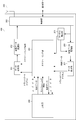
- FIG. 2 is a schematic block diagram showing the configuration of the terminal according to the embodiment of the present invention.
- the terminal includes a data control unit 201, a transmission data modulation unit 202, a radio unit 203, a scheduling unit 204, a channel estimation unit 205, a reception data demodulation unit 206, a data extraction unit 207, an upper layer 208, an antenna 209.
- the data control unit 201, transmission data modulation unit 202, radio unit 203, scheduling unit 204, upper layer 208, and antenna 209 constitute a transmission unit.
- the radio unit 203, scheduling unit 204, channel estimation unit 205, reception data demodulation unit 206, data extraction unit 207, higher layer 208, and antenna 209 constitute a reception unit.
- each part which comprises a terminal is also called a unit.
- the data control unit 201 receives the transport channel from the scheduling unit 204. Further, the data control unit 201 maps signals generated in the transport channel and the physical layer to the physical channel based on the scheduling information input from the scheduling unit 204. Each mapped data is output to transmission data modulation section 202.
- the transmission data modulation unit 202 modulates / encodes transmission data.
- Transmission data modulation section 202 performs signal processing such as modulation / coding, input signal serial / parallel conversion, IFFT processing, CP insertion on the data input from data control section 201 to generate transmission data.
- signal processing such as modulation / coding, input signal serial / parallel conversion, IFFT processing, CP insertion on the data input from data control section 201 to generate transmission data.
- the radio unit 203 up-converts the transmission data input from the transmission data modulation unit 202 to a radio frequency to generate a radio signal, and transmits the radio signal to the base station via the antenna 209.
- Radio section 203 receives a radio signal received from the base station via antenna 209, down-converts it to a baseband signal, and outputs the received data to channel estimation section 205 and received data demodulation section 206. .
- the scheduling unit 104 performs mapping between logical channels and transport channels, downlink and uplink scheduling, and the like. Since the scheduling unit 204 controls the processing units of each physical layer in an integrated manner, the scheduling unit 204, the antenna 209, the data control unit 201, the transmission data modulation unit 202, the channel estimation unit 205, the reception data demodulation unit 206, the data There is an interface between the extraction unit 207 and the wireless unit 203.
- the scheduling unit 204 performs reception control and scheduling information on the transport channel and the physical channel based on downlink control information received from the base station, scheduling information input from the higher layer 208, and the like. Generate.
- the scheduling information used for downlink scheduling is output to the data control unit 201.
- the scheduling unit 204 determines the uplink logical channel input from the upper layer 208 based on the downlink control information received from the base station, the scheduling information input from the upper layer 208, and the like. Scheduling processing for mapping to the transport channel and generation of scheduling information used for uplink scheduling are performed. The scheduling information is output to the data control unit 201.
- the scheduling unit 204 maps the uplink logical channel input from the higher layer 208 to the transport channel, and outputs it to the data control unit 201.
- the scheduling unit 204 also includes channel state information input from the channel estimation unit 205 and CRC (Cyclic Redundancy Check) parity bits (also simply referred to as CRC) input from the data extraction unit 207.
- CRC Cyclic Redundancy Check
- the confirmation result is also output to the data control unit 201.
- the scheduling unit 204 determines parameters related to the uplink signal, and generates an uplink signal using the determined parameter. In addition, the scheduling unit 204 determines a parameter related to the reference signal, and generates a reference signal using the determined parameter.
- the channel estimation unit 205 estimates a downlink channel state from a downlink reference signal (for example, a demodulation reference signal) and outputs the downlink channel state to the reception data demodulation unit 206 in order to demodulate the downlink data.
- Received data demodulation section 206 demodulates the received data input from radio section 203 and outputs the demodulated data to data extraction section 207.
- the data extraction unit 207 confirms the correctness of the reception data input from the reception data demodulation unit 206 and outputs a confirmation result (for example, ACK or NACK) to the scheduling unit 204. Further, the data extraction unit 207 separates the reception data input from the reception data demodulation unit 206 into transport channel and physical layer control data, and outputs the data to the scheduling unit 204.
- a confirmation result for example, ACK or NACK
- the upper layer 208 performs processing of the radio resource control layer and processing of the MAC layer.
- the upper layer 208 integrates and controls the processing units of the lower layer, so that the upper layer 208, the scheduling unit 204, the antenna 209, the data control unit 201, the transmission data modulation unit 202, the channel estimation unit 205, the reception data demodulation unit 206, an interface between the data extraction unit 207 and the wireless unit 203 exists.
- FIG. 3 is a schematic diagram showing an example of communication according to the embodiment of the present invention.
- terminal 303 communicates with primary base station 301 and / or secondary base station 302.
- the terminal 304 communicates with the primary base station 301 and / or the secondary base station 302.
- the uplink signal when transmitting an uplink signal to a base station, a terminal multiplexes and transmits a demodulation reference signal (DMRS; Demodulation Reference Signal), which is a known signal, between the base station and the terminal.
- DMRS demodulation reference signal
- the uplink signal includes uplink data (uplink shared channel (UL-SCH; Uplink Shared Channel), uplink transport block).
- UL-SCH uplink shared channel
- UCI Uplink Control Information
- UL-SCH is a transport channel.
- uplink data is mapped to a physical uplink shared channel (PUSCH; Physical Uplink Shared Channel).
- uplink control information is mapped by PUSCH or a physical uplink control channel (PUCCH; Physical Uplink Control Channel). That is, in the wireless communication system, a demodulation reference signal related to PUSCH transmission (transmission on PUSCH) is supported. In addition, in a wireless communication system, a demodulation reference signal related to PUCCH transmission (transmission on PUCCH) is supported.
- a demodulation reference signal related to PUSCH transmission is also referred to as a first reference signal.
- a demodulation reference signal related to PUCCH transmission is also referred to as a second reference signal.
- the first reference signal and the second reference signal are also referred to as reference signals.
- the first reference signal is used for PUSCH demodulation.
- the first reference signal is transmitted in a resource block (also referred to as a physical resource block, a physical resource, or a resource) to which the corresponding PUSCH is mapped.
- the second reference signal is used for demodulation of PUCCH.
- the second reference signal is transmitted in a resource block to which a corresponding PUCCH is mapped.
- the terminal 303 multiplexes the reference signal with the uplink signal to be transmitted to the primary base station 301 and transmits it through the uplink 305. Further, the terminal 303 multiplexes the reference signal with the uplink signal to be transmitted to the secondary base station 302 and transmits the multiplexed signal through the uplink 306. Further, the terminal 304 multiplexes the reference signal with the uplink signal to be transmitted to the primary base station 301 and transmits the multiplexed signal through the uplink 307. Further, the terminal 304 multiplexes the reference signal with the uplink signal to be transmitted to the secondary base station 302 and transmits the multiplexed signal through the uplink 308.
- the uplink signal transmitted by the terminal 303 and the uplink signal transmitted by the terminal 304 have the same characteristics, interference occurs. Further, when the reference signal transmitted by the terminal 303 and the reference signal transmitted by the terminal 304 have the same characteristics, interference occurs. For example, when interference occurs in the reference signal transmitted by each of a plurality of terminals, the estimation accuracy of the transmission path state used for demodulating the uplink signal is greatly degraded.
- the reference signal transmitted by the terminal 303 and the reference signal transmitted by the terminal 304 it is desirable to orthogonalize the uplink signal transmitted by the terminal 303 and the uplink signal transmitted by the terminal 304. Further, it is desirable to orthogonalize the uplink signal transmitted by the terminal 303 and the uplink signal transmitted by the terminal 304. Also, it is desirable to randomize the interference between the reference signal transmitted by the terminal 303 and the reference signal transmitted by the terminal 304. Also, it is desirable to randomize the interference between the uplink signal transmitted by the terminal 303 and the uplink signal transmitted by the terminal 304.
- different cell identities can be set for the primary base station 301 and the secondary base station 302 (also referred to as Different cell IDs).
- the same cell cell identity can be set for all or part of the primary base station 301 and the secondary base station 302 (also referred to as Shared cell ID or Same cell ID).
- the cell identity is also called a physical layer cell identity (Physical layer cell identity, physical layer cell identifier).
- aggregation of a plurality of serving cells is supported in the downlink and uplink (referred to as carrier aggregation or cell aggregation).
- carrier aggregation For example, in each serving cell, a transmission bandwidth of up to 110 resource blocks can be used.
- one serving cell is defined as a primary cell (Pcell).
- Pcell primary cell
- Scell secondary cell
- a carrier corresponding to a serving cell in the downlink is defined as a downlink component carrier (DLCC).
- a carrier corresponding to a primary cell in the downlink is defined as a downlink primary component carrier (DLPCC; Downlink Primary Component Carrier).
- DLPCC Downlink Primary Component Carrier
- a carrier corresponding to a secondary cell in the downlink is defined as a downlink secondary component carrier (DLSCC; Downlink Secondary Component Carrier).
- the carrier corresponding to the serving cell in the uplink is defined as an uplink component carrier (ULCC).
- a carrier corresponding to a primary cell in the uplink is defined as an uplink primary component carrier (ULPCC; Uplink Primary Component Carrier).
- a carrier corresponding to a secondary cell in the uplink is defined as an uplink secondary component carrier (ULSCCC; Uplink Secondary Component Carrier).
- the primary base station 301 can be regarded as a primary cell
- the secondary base station 302 can be regarded as a secondary cell (the base station sets the terminal) (also referred to as HetNet deployment with a carrier aggregation).
- FIG. 4 is a diagram illustrating an example of a downlink signal.
- FIG. 4 shows the resource area of the physical downlink shared channel (PDSCH) to which downlink data (downlink shared channel (DL-SCH), downlink transport block), downlink transport block) is mapped. It is shown.
- DL-SCH is a transport channel.
- a resource area of a physical downlink control channel (PDCCH; Physical Downlink Control PDCCH) to which downlink control information (DCI; Downlink Control Information) is mapped is shown.
- a resource region of E-PDCCH (Enhanced-PDCCH) to which downlink control information is mapped is shown.
- the PDCCH is mapped to the first to third OFDM symbols in the downlink resource region.
- the E-PDCCH is mapped to the 4th to 12th OFDM symbols in the downlink resource region.
- the E-PDCCH is mapped to the first slot and the second slot in one subframe.
- PDSCH and E-PDCCH are FDM (Frequency Division Multiplexing).
- E-PDCCH is included in PDCCH.
- the PDCCH is used to notify (designate) downlink control information to the terminal.
- a plurality of formats are defined for downlink control information transmitted on the PDCCH.
- the format of the downlink control information is also referred to as a DCI format.
- DCI format 1 and DCI format 1A used for scheduling one PDSCH (one PDSCH codeword, one downlink transport block transmission) in one cell are defined as DCI formats for the downlink.
- DCI format 2 used for scheduling of one PDSCH (up to two PDSCH codewords, transmission of up to two downlink transport blocks) in one cell is defined.
- the DCI format for the downlink includes downlink control information such as information related to PDSCH resource allocation and information related to MCS (Modulation and Coding scheme).
- the DCI format for the downlink may include information on a reference sequence index (also referred to as a reference sequence identifier).
- the DCI format for the downlink may include information on a reference sequence index related to PUCCH (also referred to as a reference sequence identifier related to PUCCH).
- the DCI format used for PDSCH scheduling is also referred to as downlink assignment.
- DCI format 0 used for scheduling one PUSCH (one PUSCH codeword, one uplink transport block transmission) in one cell is defined as a DCI format for uplink.
- DCI format 4 used for scheduling of one PUSCH (up to two PUSCH codewords, transmission of up to two uplink transport blocks) in one cell is defined. The That is, DCI format 4 is used for scheduling transmission (transmission mode) on PUSCH using a plurality of antenna ports.
- the DCI format for the uplink includes downlink control information such as information on PUSCH resource allocation and information on MCS (Modulation and Coding scheme). Further, the DCI format for the uplink may include information on the reference sequence index. Further, the DCI format for uplink may include information for instructing validity or invalidity of sequence group hopping and / or sequence hopping.
- the DCI format used for PUSCH scheduling is also referred to as an uplink grant.
- PDSCH is used for transmission of downlink data. Furthermore, the PDSCH is used to notify (designate) a random access response grant to the terminal.
- the random access response grant is used for PUSCH scheduling.
- the random access response grant is instructed to the physical layer by an upper layer (for example, the MAC layer).
- the base station transmits a random access response including the random access response grant in the random access response transmitted as the message 2 in the random access procedure. Further, the base station transmits a random access response grant corresponding to the message 1 transmitted by the terminal in the random access procedure. In addition, the base station transmits a random access response grant for transmission of message 3 in the random access procedure. That is, the random access response grant can be used to schedule a PUSCH for transmission of message 3 in a random access procedure.
- the terminal monitors a set of PDCCH candidates (PDCCH candidates).
- the PDCCH candidate indicates a candidate in which the PDCCH may be arranged and transmitted by the base station.
- the PDCCH candidate is configured by one or a plurality of control channel elements (CCE).
- CCE control channel elements
- monitoring means that the terminal attempts to decode each PDCCH in the set of PDCCH candidates according to all the DCI formats to be monitored.
- the set of PDCCH candidates monitored by the terminal is also called a search space. That is, a search space is a set of resources that may be used for PDCCH transmission by a base station.
- a common search space (CSS; Common Search Space) and user equipment specific search space (USS; UE-Specific Search Space, terminal-specific (terminal-specific) search space) are configured in the PDCCH resource area. (Defined and set).
- CSS and / or USS are configured in the PDCCH resource region. Also, CSS and / or USS are configured in the resource area of E-PDCCH.
- the terminal monitors the PDCCH in the CSS and / or USS of the PDCCH resource area, and detects the PDCCH addressed to itself. Also, the terminal monitors the E-PDCCH in the CSS and / or USS of the E-PDCCH resource region, and detects the E-PDCCH addressed to the terminal itself.
- CSS is used for transmission of downlink control information to a plurality of terminals. That is, CSS is defined by resources common to a plurality of terminals.
- the CSS is composed of CCEs having a predetermined number between the base station and the terminal.
- the CSS is composed of CCEs having indexes from 0 to 15.
- CSS may be used for transmission of downlink control information to a specific terminal. That is, the base station transmits a DCI format intended for a plurality of terminals and / or a DCI format intended for a specific terminal in the CSS.
- USS is used for transmission of downlink control information to a specific terminal. That is, USS is defined by resources dedicated to a certain terminal. That is, USS is defined independently for each terminal.
- the USS is composed of a radio network temporary identifier (RNTI) assigned by a base station, a CCE having a number determined based on a slot number in a radio frame, an aggregation level, and the like.
- RNTI includes C-RNTI (Cell RNTI) and Temporary C-RNTI. That is, the base station transmits a DCI format intended for a specific terminal in the USS.
- the RNTI assigned to the terminal by the base station is used for transmission of the downlink control information (transmission on the PDCCH).
- a CRC Cyclic Redundancy Check; cyclic redundancy check parity bit (also simply referred to as CRC) generated based on downlink control information (which may be in a DCI format) is added to the downlink control information, After being added, the CRC parity bits are scrambled with the RNTI.
- the terminal attempts to decode the downlink control information with CRC parity bits scrambled by RNTI, and detects the PDCCH for which the CRC was successful as the PDCCH addressed to itself (also referred to as blind decoding).
- RNTI includes C-RNTI and Temporary C-RNTI. That is, the terminal decodes the PDCCH with CRC scrambled by C-RNTI. Also, the terminal decodes the PDCCH with CRC scrambled by the Temporary C-RNTI.
- C-RNTI is a unique (unique) identifier used for identification of RRC (Radio Resource Control, radio resource control) connection and scheduling.
- C-RNTI is utilized for dynamically scheduled unicast transmissions.
- Temporary C-RNTI is an identifier used for the random access procedure.
- the base station transmits the Temporary C-RNTI included in the random access response.
- Temporary C-RNTI is used in a random access procedure to identify a terminal performing a random access procedure.
- the Temporary C-RNTI is used for retransmission of the message 3 in the random access procedure. That is, the base station transmits the downlink control information on the PDCCH with the CRC scrambled by the Temporary C-RNTI in order for the terminal to retransmit the message 3. That is, the terminal changes the interpretation of the downlink control information based on which RNTI the CRC is scrambled with.
- the terminal executes a random access procedure in order to synchronize with the base station in the time domain.
- the terminal executes a random access procedure in order to establish an initial connection (initial connection establishment).
- the terminal also executes a random access procedure for handover.
- the terminal performs a random access procedure for connection re-eatability.
- the terminal executes a random access procedure to request UL-SCH resources.
- the terminal When the PDSCH resource is scheduled by the downlink control information transmitted on the PDCCH, the terminal receives the downlink data on the scheduled PDSCH. Also, when the PUSCH resource is scheduled by the downlink control information transmitted on the PDCCH, the terminal transmits uplink data and / or uplink control information on the scheduled PUSCH. As described above, the terminal attempts to decode the downlink control information with the CRC parity bits scrambled by the RNTI, and detects the PDCCH in which the CRC is successful as the PDCCH addressed to the own device.
- RNTI includes C-RNTI and Temporary C-RNTI.
- the first reference signal is multiplexed on the uplink data and / or uplink control information transmitted on the PUSCH.
- the terminal transmits uplink control information using PUCCH.
- the terminal transmits information indicating ACK / NACK for downlink data (HARQ; also called ACK / NACK in Hybrid Automatic Repeat Request) using PUCCH.
- the terminal corresponds to the number of the first CCE used for PDCCH transmission (used for downlink assignment transmission) (also called the lowest CCE index used to configure the PDCCH).
- the uplink control information is transmitted using the PUCCH resource to be used.
- the second reference signal is multiplexed for transmission of the uplink control information transmitted on the PUCCH.
- the base station and the terminal transmit and receive signals in an upper layer (Higher layer).
- the base station and the terminal are also referred to as a radio resource control signal (RRC signaling; Radio Resource Control signal, RRC message; Radio Resource Control message, RRC information; Radio Resource Control designation).
- RRC signaling Radio Resource Control signal
- RRC message Radio Resource Control message
- RRC information Radio Resource Control designation
- Send and receive
- a dedicated signal transmitted to a certain terminal by the base station is also referred to as a dedicated signal (dedicated signal). That is, a setting (information) unique to a certain terminal is notified by a base station using a dedicated signal.
- the base station and the terminal transmit and receive MAC control elements in a MAC (Media Access Control) layer (layer 2).
- MAC Media Access Control
- the RRC signaling and / or the MAC control element is also referred to as an upper layer signal (higher layer signaling).
- the reference signal sequence is used to generate a first reference signal sequence.
- the reference signal sequence is used to generate a second reference signal sequence.
- the reference signal sequence, reference sequence r ⁇ ( ⁇ ) u, by cyclic shift of [nu (n), is defined according to Equation 1.
- a cyclic shift ⁇ is applied to the reference sequence, and a reference signal sequence is generated. Further, a plurality of reference signal sequences are defined from a single reference sequence by different cyclic shift ⁇ values.
- N SC RB is the size of the resource block in the frequency domain, and is represented by the number of subcarriers, for example.
- the reference series is divided into groups. That is, the reference sequence is represented by a group number (also referred to as a sequence group number) u and a reference sequence number ⁇ in the group.
- the reference sequence is divided into 30 groups, and each group includes two reference sequences.
- sequence group hopping is applied to 30 groups.
- sequence hopping is applied to two reference sequences in one group.
- each of the sequence group number u and the reference sequence number ⁇ can change in time.
- the definition of the reference sequence depends on the sequence length M SC RS .
- M SC RS 3N SC RB
- the reference sequence is given by Equation 2.
- Equation 3 the q-th root Zadoff-Chu sequence x q (m) is defined by Equation 3.
- N ZC RS of the Zadoff-Chu sequence is given by the maximum prime number satisfying N ZC RS ⁇ M SC RS .
- sequence group number u in slot n s is the group hopping pattern f gh (n s) and sequence shift pattern f ss, defined according to Equation 5.
- the base station can instruct the terminal to enable or disable sequence group hopping (also simply referred to as group hopping).
- sequence group hopping also simply referred to as group hopping
- the base station can instruct validity / invalidity of sequence group hopping based on a cell-specific parameter (cell-specific).
- the condition is B
- the base station can instruct validity / invalidity of sequence group hopping based on parameters specific to the terminal (user equipment specific; UE-specific).
- UE-specific user equipment specific
- the terminal when the terminal is instructed by the base station to enable sequence group hopping, the terminal hops a group of reference signal sequences for each slot. That is, the terminal determines whether or not to hop a group of reference signal sequences for each slot according to validity or invalidity of sequence group hopping.
- group hopping pattern f gh (n s) is given by Equation 6.
- the pseudo-random sequence c (i) is defined by Equation 7.
- the pseudo-random sequence is defined by a gold sequence of length 31 and is given by Equation 7.
- N c 1600.
- the second m-sequence x 2 is initialized by Equation 8.
- Equation 9 the pseudo-random sequence of group hopping pattern f gh (n s) is initialized by Equation 9.
- sequence shift pattern f ss is different between PUSCH and PUCCH.
- the sequence shift pattern f ss PUCCH is given by Equation 10.
- the sequence shift pattern f ss PUSCH is given by Equation 11 with respect to PUSCH .
- the reference sequence number ⁇ within the reference sequence group in slot n s is defined by Equation 12.
- the base station can instruct the terminal whether the sequence hopping is valid or invalid.
- the condition is A
- the base station can instruct validity / invalidity of sequence hopping based on a cell-specific parameter.
- the condition is B
- the base station can instruct validity / invalidity of sequence hopping based on the parameters specific to the terminal.
- the terminal hops the sequence for each slot within the group. That is, the terminal determines whether or not to hop a sequence for each slot in the group in accordance with validity or invalidity of sequence hopping.
- Equation 7 the pseudo-random sequence c (i) is defined by Equation 7 and Equation 8.
- C init is defined by Equation 13. That is, the pseudo-random sequence with the reference sequence number ⁇ is initialized by Equation 13.
- a method for generating a first reference signal sequence will be described below. That is, a method for generating a demodulation reference signal for PUSCH is described.
- M SC PUSCH to the uplink transmission (transmission on the PUSCH), a scheduled bandwidth by the base station, for example, represented by the number of subcarriers.
- w ( ⁇ ) (m) represents an orthologous sequence.
- Equation 15 the cyclic shift applied to the first reference signal related to PUSCH is defined by Equation 15.
- n (1) DMRS is notified by the base station apparatus using an upper layer signal.
- n (2) DMRS, ⁇ is instructed by the base station apparatus using the DCI format.
- n PN (n s ) is given by Equation 16.
- Equation 7 the pseudo-random sequence c (i) is defined by Equation 7 and Equation 8.
- C init is defined by Equation 17. That is, the cyclic shift applied to the first reference signal related to PUSCH is initialized by Equation 17.
- PUCCH demodulation reference signal sequence ⁇ (P) PUCCH ( ⁇ ) is defined by Equation 18.
- p is the number of antenna ports used for PUCCH transmission (transmission on PUCCH).
- Equation 19 the cyclic shift applied to the second reference signal related to PUCCH is defined by Equation 19.
- n ′ P (n s ), N ′, and ⁇ shift PUCCH are determined based on information notified by the base station.
- the slot M number of RS PUCCH Atari reference symbols and sequence w (n) is defined by such specification.
- Equation 20 The cyclic shift n cs cell ( ns, l) is defined by Equation 20.
- N sym UL is the number of symbols in the uplink slot (number of SC-FDMA symbols).
- the pseudo-random sequence c (i) is defined by Equation 7 and Equation 8.
- C init is defined by Equation 21 or Equation 22. That is, the cyclic shift applied to the second reference signal related to PUCCH is initialized by Equation 21 or Equation 22.
- the same parameter “X” can be used for the generation of the first reference signal and the generation of the second reference signal. That is, the parameter “X” used for generating the first reference signal can be used for generating the second reference signal, and the parameter can be set using the radio resource efficiently. it can.
- the cyclic shift applied to the PUCCH is generated using Equation 20.
- C init is defined by Equation 21 or Equation 22. That is, the terminal can transmit the uplink signal generated using Equation 20 and Equation 21 on the PUCCH. Or a terminal can transmit the uplink signal produced
- N ID cell indicates a physical layer cell identity (also referred to as a physical layer cell identity). That is, the N ID cell indicates a cell (base station) specific (cell (base station) specific) identity. That is, the N ID cell indicates the physical layer identity of the cell.
- the N ID cell may be an N ID cell corresponding to the primary cell.
- the terminal can detect the N ID cell using a synchronization signal (Synchronization signals). Also, the terminal can obtain the N ID cell from information included in a higher layer signal (for example, a band over command) transmitted by the base station.
- a synchronization signal for example, Synchronization signals
- the terminal can obtain the N ID cell from information included in a higher layer signal (for example, a band over command) transmitted by the base station.
- N ID cell is a parameter related to the reference signal sequence (parameter related to generation of the reference signal sequence). That is, N ID cell is a parameter related to the first reference signal (parameter related to generation of the first reference signal sequence). N ID cell is a parameter related to the second reference signal (parameter related to generation of the second reference signal sequence). N ID cell is a parameter related to PUCCH (a parameter related to generation of an uplink signal transmitted on PUCCH).
- the parameter ⁇ ss is represented by ⁇ ss ⁇ ⁇ 0, 1,..., 29 ⁇ .
- the parameter ⁇ ss is a parameter specific to the cell (base station).
- the terminal can receive the parameter ⁇ ss using SIB2 (System Information Block Type 2).
- SIB2 is a common setting (common information) for all terminals (may be a plurality of terminals) in the cell.
- the terminal is assigned the parameter ⁇ ss using information common to all terminals in the cell. That is, the parameter ⁇ ss is a parameter related to the first reference signal.
- the parameter “X” (value of the parameter “X”) indicates a virtual cell identity (also referred to as a virtual cell identity). That is, the parameter “X” indicates a terminal-specific identity. That is, the parameter “X” indicates a parameter specific to the terminal.
- the parameter “X” is a parameter related to the reference signal sequence. That is, the parameter “X” is a parameter related to the first reference signal. The parameter “X” is a parameter related to the second reference signal. The parameter “X” is a parameter related to PUCCH. *
- the parameter “Y” (value of the parameter “Y”) is indicated by “Y” ⁇ ⁇ 0, 1,..., 29 ⁇ .
- the parameter “Y” indicates a parameter unique to the terminal. That is, the parameter “Y” is a parameter related to the first reference signal.
- the parameter “Z” (the value of the parameter “Z”) indicates the initial value of the second m-sequence.
- the parameter “Z” indicates a parameter specific to the terminal. That is, the parameter “Z” is a parameter related to the first reference signal.
- the parameter “K” (the value of the parameter “K”) indicates the initial value of the second m-sequence.
- the parameter “K” indicates a parameter unique to the terminal. That is, the parameter “K” is a parameter related to PUCCH.
- the base station can instruct validity / invalidity of sequence group hopping and / or sequence hopping using parameter “M” (value of parameter “M”).
- M value of parameter “M”.
- the parameter “M” is set to “1”.
- sequence group hopping and / or sequence hopping is invalid, the parameter “M” is set to “0”.
- the parameter “M” indicates a parameter specific to the terminal.
- the parameter “M” is a parameter related to the reference signal sequence. That is, the parameter “M” is a parameter related to the first reference signal. The parameter “M” is a parameter related to the second reference signal.
- the base station can set the parameter “X” in the terminal using the upper layer signal.
- the base station can set the parameter “X” using a dedicated signal.
- the base station sets a plurality of parameters “X” using a dedicated signal, and one parameter “X” is transmitted from the set plurality of parameters “X” on the PDCCH.
- the information about the reference sequence index or the reference sequence index related to PUCCH may be used to indicate.
- downlink control information for indicating the parameter “X” is included in the uplink grant. Further, downlink control information for instructing the parameter “X” may be included in the downlink assignment.
- the base station sets (X 0 ) and (X 1 ) as a plurality of parameters “X”, and uses downlink control information (for example, 1-bit information) transmitted on the PDCCH, and 0) or (X 1) can instruct.
- downlink control information for example, 1-bit information
- the base station can set the parameter “Y” to the terminal using the upper layer signal.
- the base station can set the parameter “Y” using a dedicated signal.
- the base station sets a plurality of parameters “Y” using a dedicated signal, and downlink control information in which one parameter “Y” is transmitted on the PDCCH from among the set parameters “Y”. (For example, information regarding the reference sequence index) may be used for the instruction. That is, downlink control information for indicating the parameter “Y” is included in the uplink grant.
- the base station sets a plurality of parameters "Y" and (Y 0) to (Y 1), using the downlink control information transmitted by the PDCCH (e.g., 1-bit information), (Y 0 ) or (Y 1 ) can be indicated.
- the downlink control information transmitted by the PDCCH e.g., 1-bit information
- (Y 0 ) or (Y 1 ) can be indicated.
- the base station can set the parameter “Z” in the terminal using the upper layer signal.
- the base station can set the parameter “Z” using a dedicated signal.
- the base station sets a plurality of parameters “Z” using a dedicated signal, and one parameter “Z” from among the set parameters “Z” is transmitted on the PDCCH. (For example, information regarding the reference sequence index) may be used for the instruction. That is, downlink control information for indicating the parameter “Z” is included in the uplink grant.
- the base station sets (Z 0 ) and (Z 1 ) as a plurality of parameters “Z”, and uses downlink control information (for example, 1-bit information) transmitted on the PDCCH, to 0 ) or (Z 1 ) can be indicated.
- downlink control information for example, 1-bit information
- the base station can set the parameter “K” in the terminal using the upper layer signal.
- the base station can set the parameter “K” using a dedicated signal.
- the base station sets a plurality of parameters “K” using a dedicated signal, and downlink control information in which one parameter “K” is transmitted by PDCCH from among the plurality of set parameters “K”. (For example, information regarding a reference sequence index related to PUCCH) may be used to indicate. That is, downlink control information for indicating the parameter “K” is included in the downlink assignment.
- the base station sets (K 0 ) and (K 1 ) as a plurality of parameters “K”, and uses downlink control information (for example, 1-bit information) transmitted on the PDCCH, to (K 0 ) or (K 1 ) can be indicated.
- downlink control information for example, 1-bit information
- the base station can set the parameter “M” in the terminal using the upper layer signal.
- the base station can set the parameter “M” using a dedicated signal.
- the base station sets a plurality of parameters “M” using the dedicated signal, and downlink control information transmitted from the set plurality of parameters “M” using the PDCCH as one parameter “M”. (For example, information for instructing validity or invalidity of sequence group hopping and / or sequence hopping) may be used. That is, downlink control information for indicating the parameter “M” is included in the uplink grant.
- the base station sets (M 0 ) and (M 1 ) as a plurality of parameters “M”, and uses the downlink control information (for example, 1-bit information) transmitted on the PDCCH, (M 0 ) or (M 1 ) can be indicated.
- the downlink control information for example, 1-bit information
- the base station may use multiple sets of parameter “X” and / or parameter “Y” and / or parameter “Z” and / or parameter “K” and / or parameter “M” using a dedicated signal.
- Downlink control information for example, information related to a reference sequence index, information related to a reference sequence index related to PUCCH, sequence group hopping, and group control hopping). The information may also be indicated using information for indicating validity / invalidity of sequence hopping.
- downlink control information for indicating one set from among a plurality of sets is included in the uplink grant. Further, downlink control information for indicating one set from among a plurality of sets may be included in the downlink assignment.
- the parameter “X”, the parameter “Y”, the parameter “Z”, the parameter “K”, and the parameter “M” may be set independently.
- the parameter “X” and / or the parameter “Y” and / or the parameter “Z” and / or the parameter “K” may be set in association with each other.
- the base station notifies only the parameter “X” to the terminal, whereby the parameter “Y” and / or the parameter “Z” and / or the parameter “K” and / or the parameter “ M ′′ can be indicated.
- the association between the parameter “X”, the parameter “Y” and / or the parameter “Z” and / or the parameter “K” and / or the parameter “M” is defined in advance according to the specification, etc. This can be known information in the terminal.
- the base station sets (X 0, Y 0, Z 0, K 0 ) and (X 1, Y 1, Z 1, K 1 ) as multiple sets of parameters, and is transmitted on the PDCCH.
- Control information eg, 1-bit information
- the terminal uses the parameters (X 0, Y 0, Z 0, K 0 ). Is used to generate the first reference signal.
- the terminal the downlink control information transmitted by PDCCH, if the parameter (X 1, Y 1, Z 1, K 1) is instructed, the parameters (X 1, Y 1, Z 1, K 1 ) is used to generate the first reference signal.
- the terminal uses the parameters (X 0, Y 0, Z 0, K 0 ) is used to generate the second reference signal.
- the terminal the downlink control information transmitted by PDCCH, if the parameter (X 1, Y 1, Z 1, K 1) is instructed, the parameters (X 1, Y 1, Z 1, K 1 ) is used to generate a second reference signal.
- the base station can transmit the parameter “M” in each of the parameter sets. That is, the base station can instruct each group of parameters whether sequence group hopping and / or sequence hopping is enabled or disabled.
- downlink control information for example, 1-bit information
- the terminal uses the parameters (X 0, Y 0 , Z 0 ) and enabling sequence group hopping to generate the first reference signal.
- the downlink control information for instructing the parameter and / or the downlink control information for instructing the parameter “K” and / or the downlink control information for instructing the set of parameters, the parameter is indicated For downlink control information.
- the downlink control information for indicating the parameter may be included in the uplink grant only when the parameter is set by the base station using the higher layer signal. Also, the downlink control information for indicating the parameter may be included in the downlink assignment only when the parameter is set by the base station using the higher layer signal.
- the base station can instruct whether or not downlink control information for indicating a parameter is included in the uplink grant using a dedicated signal. Also, the base station can instruct whether the downlink control information for instructing the parameter is included in the downlink assignment by using the dedicated signal.
- the base station indicates a parameter by setting a downlink transmission mode (for example, a transmission mode in PDSCH) and / or an uplink transmission mode (for example, a transmission mode in PUSCH) using a dedicated signal. Whether or not the downlink control information to be included in the uplink grant can be instructed. Also, the downlink assignment includes downlink control information for indicating parameters by setting the downlink transmission mode and / or the uplink transmission mode using the dedicated signal. Whether or not can be instructed.
- a downlink transmission mode for example, a transmission mode in PDSCH
- an uplink transmission mode for example, a transmission mode in PUSCH
- the terminal identifies that downlink control information for indicating a parameter is included in the uplink grant only when a specific downlink transmission mode and / or uplink transmission mode is set. can do. Also, the terminal assigns that downlink control information for indicating parameters is included in the downlink assignment only when a specific downlink transmission mode and / or uplink transmission mode is set. Can be identified.
- a specific downlink transmission mode and / or uplink transmission mode is defined in advance by specifications or the like, and can be known information between the base station and the terminal.
- the base station determines that the downlink control information for indicating the parameter is included in the uplink grant and that the downlink control information for indicating the parameter is included in the downlink assignment.
- Information may be used to set (instruct).
- the base station can transmit a single piece of information using a dedicated signal.
- the base station can transmit the downlink transmission mode and / or the uplink transmission mode as a single piece of information.
- the base station may include the downlink control information for instructing the parameter only in the uplink grant transmitted in the user equipment specific search space. Further, the base station may include the downlink control information for indicating the parameter only in the downlink assignment transmitted in the user apparatus specific search space.
- a default value may be set in the downlink control information for indicating the parameter. That is, the terminal can use the default value until the parameter is set by the base station.
- the default value is defined in advance by specifications or the like and can be known information between the base station and the terminal.
- the default value of the parameter “X” may be N ID cell .
- the parameter default values for "Y” may be a value of the parameter delta ss.
- the default value of the parameter “Y” may be specified by the base station using SIB2.
- the default value of the parameter “Y” may be “0”.
- the default value of the parameter “Z” may be calculated according to Equation 17 (1).
- f ss PUSCH in Expression 17 (1) may be calculated based on the parameter ⁇ ss designated by the base station using SIB2.
- the default value of the parameter “K” may be N ID cell (for example, N ID cell corresponding to the primary cell ).
- the default value of the parameter “M” may be “invalid”.
- the physical layer cell identity N ID cell and / or the parameter ⁇ ss is also referred to as a first parameter.
- the parameter “X” and / or the parameter “Y” and / or the parameter “Z” and / or the parameter “K” and / or the parameter “M” are also described as the second parameter.
- the terminal identifies a condition, and switches a parameter related to the first reference signal (or generation of the first reference signal sequence) based on the condition. That is, when the condition is A, the terminal generates the first reference signal using the first parameter in the above formula.
- the terminal identifies the condition and switches a parameter related to the second reference signal (may generate a second reference signal sequence) based on the condition. That is, when the condition is A, the terminal generates the second reference signal using the first parameter in the above formula.
- the terminal identifies a condition and switches a parameter related to PUCCH (may generate an uplink signal transmitted on PUCCH) based on the condition. That is, when the condition is A, the terminal generates an uplink signal transmitted on the PUCCH using the first parameter in the above formula.
- the terminal transmits the first reference signal (which may be a part of the first reference signal sequence) generated by using the first parameter to the PUSCH (PUSCH).
- the first reference signal (which may be a part of the first reference signal sequence) generated by using the first parameter to the PUSCH (PUSCH).
- the terminal transmits the second reference signal (which may be a part of the second reference signal sequence) generated using the first parameter to PUCCH transmission (in PUCCH).
- the second reference signal (which may be a part of the second reference signal sequence) generated using the first parameter to PUCCH transmission (in PUCCH).
- the terminal transmits the uplink signal generated using the first parameter to the resource element in the resource block allocated for PUCCH transmission (transmission on PUCCH). Map.
- the base station identifies the condition, and switches the parameter related to the first reference signal (or generation of the first reference signal sequence) based on the condition. That is, when the condition is A, the base station assumes that the first reference signal is generated using the first parameter in the above formula.
- the base station identifies the condition and switches a parameter related to the second reference signal (may generate a second reference signal sequence) based on the condition. That is, when the condition is A, the base station assumes that the second reference signal is generated using the first parameter in the above formula.
- the base station identifies a condition and switches a parameter related to PUCCH (may generate an uplink signal transmitted on PUCCH) based on the condition. That is, when the condition is A, the base station assumes that an uplink signal transmitted on the PUCCH is generated using the first parameter in the above formula.
- the base station transmits the first reference signal (which may be part of the first reference signal sequence) generated using the first parameter to the PUSCH ( Assume that it is mapped to a resource element in a resource block allocated for transmission on the PUSCH.
- the base station transmits the second reference signal generated using the first parameter (may be a part of the second reference signal sequence) to transmit the PUCCH ( Assume that it is mapped to a resource element in the resource block allocated for transmission on the PUCCH.
- the base station uses the resource in the resource block to which the uplink signal generated using the first parameter is allocated for PUCCH transmission (transmission on PUCCH). Assume that it is mapped to an element.
- the terminal when the condition is B, the terminal generates the first reference signal using the second parameter in the above formula. Further, when the condition is B, the terminal generates the second reference signal using the second parameter in the above formula. Further, when the condition is B, the terminal generates an uplink signal transmitted on the PUCCH using the second parameter in the above formula.
- the terminal transmits the first reference signal (which may be a part of the first reference signal sequence) generated by using the second parameter to the PUSCH transmission (PUSCH).
- the first reference signal (which may be a part of the first reference signal sequence) generated by using the second parameter to the PUSCH transmission (PUSCH).
- PUSCH PUSCH transmission
- the terminal transmits the second reference signal (which may be a part of the second reference signal sequence) generated using the second parameter to PUCCH transmission (in PUCCH).
- the second reference signal (which may be a part of the second reference signal sequence) generated using the second parameter to PUCCH transmission (in PUCCH).
- the terminal transmits the uplink signal generated using the second parameter to the resource element in the resource block allocated for PUCCH transmission (transmission on PUCCH). Map.
- the base station assumes that the first reference signal is generated using the second parameter in the above formula.
- the terminal assumes that the second reference signal is generated using the second parameter in the above formula.
- the terminal assumes that an uplink signal transmitted on the PUCCH is generated using the second parameter in the above formula.
- the base station transmits the first reference signal (which may be part of the first reference signal sequence) generated using the second parameter to the PUSCH ( Assume that it is mapped to a resource element in a resource block allocated for transmission on the PUSCH.
- the base station transmits the second reference signal (which may be part of the second reference signal sequence) generated using the second parameter to the PUCCH transmission ( Assume that it is mapped to a resource element in the resource block allocated for transmission on the PUCCH.
- the base station uses the resource in the resource block to which the uplink signal generated using the second parameter is allocated for PUCCH transmission (transmission on PUCCH). Assume that it is mapped to an element.
- the condition A includes the detection (decoding) of the PDCCH in the CSS. That is, when the terminal detects PDCCH in CSS, the terminal transmits the first reference signal generated using the first parameter. Further, when the terminal detects PDCCH in CSS, the terminal transmits a second reference signal generated using the first parameter. Further, when the terminal detects PDCCH in CSS, the terminal transmits an uplink signal generated using the first parameter on PUCCH.
- the base station receives the second reference signal generated using the first parameter. Also, when the PDCCH is arranged in the CSS, the base station receives the second reference signal generated using the first parameter. Moreover, when PDCCH is arrange
- the terminal when a terminal detects a PDCCH in CSS, the terminal transmits a first reference signal generated using an N ID cell . Further, when the terminal detects the PDCCH in the CSS, the terminal transmits a second reference signal generated using the N ID cell . Further, when the terminal detects PDCCH in CSS, the terminal transmits an uplink signal generated using N ID cell by PUCCH. In addition, when the terminal detects the PDCCH in the CSS, the terminal transmits a first reference signal generated using the parameter ⁇ ss .
- condition B includes that the PDCCH is detected (decoded) in the USS. That is, when the terminal detects PDCCH in USS, the terminal transmits the first reference signal generated using the second parameter. Further, when the terminal detects PDCCH in USS, the terminal transmits a second reference signal generated using the second parameter. Further, when the terminal detects PDCCH in USS, the terminal transmits an uplink signal generated using the second parameter on PUCCH.
- the base station receives the first reference signal generated using the second parameter.
- the base station receives the second reference signal generated using the second parameter.
- a base station receives the uplink signal produced
- the terminal when the terminal detects the PDCCH in the USS, the terminal transmits the first reference signal generated using the parameter “X”. Further, when the terminal detects the PDCCH in the USS, the terminal transmits the first reference signal generated using the parameter “Y”. Further, when the terminal detects the PDCCH in the USS, the terminal transmits the first reference signal generated using the parameter “Z”.
- the terminal when the terminal detects the PDCCH in the USS, the terminal transmits the second reference signal generated using the parameter “X”. Further, when the terminal detects PDCCH in USS, the terminal transmits an uplink signal generated using parameter “X” on PUCCH. Further, when the terminal detects the PDCCH in the USS, the terminal transmits a second reference signal generated using the parameter “K”. Further, when the terminal detects PDCCH in the USS, the terminal transmits an uplink signal generated using the parameter “K” on PUCCH.
- downlink control information for example, information on a reference sequence index, information on a reference sequence index related to PUCCH
- downlink control information for example, information on a reference sequence index, information on a reference sequence index related to PUCCH
- the terminal transmits a first reference signal generated by a different method (using different parameters) to the base station based on the search space in which the PDCCH is detected. That is, the terminal generates the first reference signal by a different method based on whether PDCCH is detected in CSS or USS.
- the terminal transmits a second reference signal generated by a different method to the base station based on the search space where the PDCCH is detected. That is, the terminal generates the second reference signal by a different method based on whether PDCCH is detected in CSS or USS.
- the terminal transmits an uplink signal generated by a different method on the PUCCH based on the search space where the PDCCH is detected. That is, the terminal transmits an uplink signal generated by a different method on the PUCCH based on whether the PDCCH is detected in the CSS or the USS.
- the condition A includes the detection (decoding) of the PDCCH with CRC scrambled by the Temporary C-RNTI. That is, when the terminal detects a PDCCH with a CRC scrambled by Temporary C-RNTI, the terminal transmits a first reference signal generated using the first parameter. In addition, when the terminal detects a PDCCH with a CRC scrambled by Temporary C-RNTI, the terminal transmits a second reference signal generated using the first parameter. Also, when the terminal detects a PDCCH with a CRC scrambled by Temporary C-RNTI, the terminal transmits an uplink signal generated using the first parameter on the PUCCH.
- the base station receives the first reference signal generated using the first parameter.
- the base station receives the second reference signal generated using the first parameter.
- the base station receives the uplink signal generated using the first parameter on the PUCCH.
- the terminal when the terminal detects a PDCCH with a CRC scrambled by Temporary C-RNTI, the terminal transmits a first reference signal generated using the N ID cell . Also, when the terminal detects a PDCCH with a CRC scrambled by Temporary C-RNTI, the terminal transmits a second reference signal generated using the N ID cell . Also, when the terminal detects a PDCCH with a CRC scrambled by Temporary C-RNTI, the terminal transmits an uplink signal generated using the N ID cell by PUCCH. Further, when the terminal detects a PDCCH with a CRC scrambled by Temporary C-RNTI, the terminal transmits a first reference signal generated using the parameter ⁇ ss .
- the condition B includes the detection (decoding) of the PDCCH accompanied by the CRC scrambled by the C-RNTI. That is, when a terminal detects a PDCCH with a CRC scrambled by C-RNTI, the terminal transmits a first reference signal generated using the second parameter. Also, when the terminal detects a PDCCH with a CRC scrambled by C-RNTI, the terminal transmits a second reference signal generated using the second parameter. Also, when the terminal detects a PDCCH with a CRC scrambled by C-RNTI, the terminal transmits an uplink signal generated using the second parameter on the PUCCH.
- the base station receives the first reference signal generated using the second parameter. Further, when the PDCCH with CRC scrambled by C-RNTI is arranged, the base station receives the second reference signal generated using the second parameter. In addition, when the PDCCH with the CRC scrambled by the C-RNTI is arranged, the base station receives the uplink signal generated using the second parameter on the PUCCH.
- the terminal when the terminal detects a PDCCH with a CRC scrambled by C-RNTI, the terminal transmits a first reference signal generated using the parameter “X”. Also, when the terminal detects a PDCCH with a CRC scrambled by C-RNTI, the terminal transmits a first reference signal generated using the parameter “Y”. Also, when the terminal detects a PDCCH with a CRC scrambled by C-RNTI, the terminal transmits a first reference signal generated using the parameter “Z”.
- the terminal when the terminal detects a PDCCH with a CRC scrambled by C-RNTI, the terminal transmits a second reference signal generated using the parameter “X”. Also, when the terminal detects a PDCCH with a CRC scrambled by C-RNTI, the terminal transmits an uplink signal generated using the parameter “X” on the PUCCH. Also, when the terminal detects a PDCCH with a CRC scrambled by C-RNTI, the terminal transmits a second reference signal generated using the parameter “K”. Also, when the terminal detects a PDCCH with a CRC scrambled by C-RNTI, the terminal transmits an uplink signal generated using the parameter “K” on the PUCCH.
- downlink control information for example, information on a reference sequence index, information on a reference sequence index related to PUCCH
- downlink control information for indicating a parameter is transmitted on a PDCCH with a CRC scrambled by C-RNTI.
- the terminal transmits a first reference signal generated by a different method (using different parameters) to the base station based on the RNTI in which the CRC is scrambled. That is, the terminal generates the first reference signal in a different manner based on whether the CRC is scrambled by the Temporary C-RNTI or the C-RNTI.
- the terminal transmits a second reference signal generated by a different method to the base station based on the RNTI in which the CRC is scrambled. That is, the terminal generates the second reference signal in a different manner based on whether the CRC is scrambled by the Temporary C-RNTI or the C-RNTI.
- the terminal transmits an uplink signal generated by a different method on the PUCCH based on the RNTI in which the CRC is scrambled. That is, the terminal generates a PUCCH signal using a different method based on whether the CRC is scrambled by the Temporary C-RNTI or the C-RNTI.
- the condition A may include detecting (decoding) a PDCCH with a CRC scrambled by C-RNTI or Temporary C-RNTI in CSS. That is, when the terminal detects a PDCCH with CRC scrambled by C-RNTI or Temporary C-RNTI in the CSS, the terminal transmits the first reference signal generated using the first parameter. Also, when the terminal detects a PDCCH with CRC scrambled by C-RNTI or Temporary C-RNTI in the CSS, the terminal transmits a second reference signal generated using the first parameter. Also, when the terminal detects a PDCCH with CRC scrambled by C-RNTI or Temporary C-RNTI in CSS, the terminal transmits an uplink signal generated using the first parameter on PUCCH.
- the base station receives the first reference signal generated using the first parameter. To do.
- the base station receives the second reference signal generated using the first parameter. To do.
- the base station receives the uplink signal generated using the first parameter on PUCCH. To do.
- the terminal when detecting a PDCCH with a CRC scrambled by C-RNTI or Temporary C-RNTI in the CSS, the terminal transmits a first reference signal generated using the N ID cell . Further, when the terminal detects a PDCCH with a CRC scrambled by C-RNTI or Temporary C-RNTI in the CSS, the terminal transmits a second reference signal generated using the N ID cell .
- the terminal in CSS, when detecting a PDCCH with the CRC scrambled by the C-RNTI or the Temporary C-RNTI transmits an uplink signal generated using N ID cell in PUCCH. Also, when the terminal detects a PDCCH with a CRC scrambled by C-RNTI or Temporary C-RNTI in the CSS, the terminal transmits a first reference signal generated using the parameter ⁇ ss .
- condition B may be included in the detection (decoding) of the PDCCH accompanied by the CRC scrambled by the C-RNTI in the USS.
- PDCCH with CRC scrambled by Temporary C-RNTI is arranged only in CSS. That is, when a terminal detects a PDCCH with a CRC scrambled by C-RNTI in the USS, the terminal transmits a first reference signal generated using the second parameter. Also, when the terminal detects a PDCCH with a CRC scrambled by C-RNTI in the USS, the terminal transmits a second reference signal generated using the second parameter. Also, when the terminal detects a PDCCH with a CRC scrambled by C-RNTI in the USS, the terminal transmits an uplink signal generated using the second parameter on the PUCCH.
- the base station when a PDCCH with a CRC scrambled by C-RNTI is arranged in the USS, the base station receives the first reference signal generated using the second parameter. In addition, when a PDCCH with a CRC scrambled by C-RNTI is arranged in the USS, the base station receives a second reference signal generated using the second parameter. In addition, when a PDCCH with a CRC scrambled by C-RNTI is arranged in the USS, the base station receives an uplink signal generated using the second parameter on the PUCCH.
- the terminal when the terminal detects a PDCCH with a CRC scrambled by C-RNTI in the USS, the terminal transmits a first reference signal generated using the parameter “X”. Also, when the terminal detects a PDCCH with a CRC scrambled by C-RNTI in the USS, the terminal transmits a first reference signal generated using the parameter “Y”. Also, when the terminal detects a PDCCH with CRC scrambled by C-RNTI in the USS, the terminal transmits a first reference signal generated using the parameter “Z”.
- the terminal when the terminal detects a PDCCH with a CRC scrambled by C-RNTI in the USS, the terminal transmits a second reference signal generated using the parameter “X”. Also, when the terminal detects a PDCCH with a CRC scrambled by C-RNTI in the USS, the terminal transmits an uplink signal generated using the parameter “X” on the PUCCH. Also, when the terminal detects a PDCCH with a CRC scrambled by C-RNTI in the USS, the terminal transmits a second reference signal generated using the parameter “K”. Also, when the terminal detects a PDCCH with a CRC scrambled by C-RNTI in the USS, the terminal transmits an uplink signal generated using the parameter “K” on the PUCCH.
- downlink control information for example, information on a reference sequence index, information on a reference sequence index related to PUCCH
- downlink control information for indicating a parameter is transmitted on a PDCCH with a CRC scrambled by C-RNTI in the USS. Is done.
- the terminal transmits a first reference signal generated by a different method (using different parameters) to the base station based on the search space in which the PDCCH is detected and the RNTI scrambled in the CRC. Also, the terminal transmits a second reference signal generated by a different method to the base station based on the search space in which the PDCCH is detected and the RNTI scrambled to the CRC. In addition, the terminal transmits, on the PUCCH, an uplink signal generated by a different method based on the search space where the PDCCH is detected and the RNTI scrambled to the CRC.
- the condition A includes receiving (detecting and decoding) a predetermined DCI format (hereinafter referred to as a first DCI format).
- the first DCI format is defined in advance by specifications or the like and can be known information between the base station and the terminal.
- the first DCI format includes DCI format 0.
- DCI format 0 is transmitted by PDCCH in CSS and / or USS.
- the terminal when the terminal receives the first DCI format, the terminal transmits the first reference signal generated using the first parameter. In addition, when the terminal receives the first DCI format, the terminal transmits a second reference signal generated using the first parameter. Further, when the terminal receives the first DCI format, the terminal transmits an uplink signal generated using the first parameter on the PUCCH.
- the base station when the first DCI format is transmitted, the base station receives the first reference signal generated using the first parameter. Further, when the base station transmits the first DCI format, the base station receives the second reference signal generated using the first parameter. In addition, when the base station transmits the first DCI format, the base station receives the uplink signal generated using the first parameter on the PUCCH.
- the terminal when receiving the first DCI format transmits a first reference signal generated using N ID cell.
- the terminal when the terminal receives the first DCI format, transmits the second reference signal generated using the N ID cell .
- the terminal transmits an uplink signal generated using the N ID cell by PUCCH.
- the terminal when receiving the first DCI format, transmits the first reference signal generated using the parameter delta ss.
- condition B includes receiving (detecting) a DCI format other than the predetermined DCI format (hereinafter, the second DCI format).
- the DCI format 4 is included in the second DCI format.
- the DCI format 4 is transmitted only by PDCCH in USS.
- the terminal when the terminal receives the second DCI format, the terminal transmits the first reference signal generated using the second parameter. In addition, when the terminal receives the second DCI format, the terminal transmits a second reference signal generated using the second parameter. Further, when the terminal receives the second DCI format, the terminal transmits an uplink signal generated using the second parameter on the PUCCH.
- the base station when the base station transmits the second DCI format, the base station receives the first reference signal generated using the second parameter. Further, when the second DCI format is transmitted, the base station receives the second reference signal generated using the second parameter. In addition, when the second DCI format is transmitted, the base station receives an uplink signal generated using the second parameter on the PUCCH.
- the terminal when the terminal receives the second DCI format, the terminal transmits the first reference signal generated using the parameter “X”. Further, when receiving the second DCI format, the terminal transmits the first reference signal generated using the parameter “Y”. When the terminal receives the second DCI format, the terminal transmits the first reference signal generated using the parameter “Z”.
- the terminal transmits the second reference signal generated using the parameter “X”. Further, when the terminal receives the second DCI format, the terminal transmits an uplink signal generated using the parameter “X” on the PUCCH. Further, when the terminal receives the second DCI format, the terminal transmits the second reference signal generated using the parameter “K”. Further, when the terminal receives the second DCI format, the terminal transmits an uplink signal generated using the parameter “K” on the PUCCH.
- downlink control information for example, a reference sequence index, a reference sequence index related to PUCCH
- downlink control information for example, a reference sequence index, a reference sequence index related to PUCCH
- the terminal transmits a first reference signal generated by a different method (using different parameters) to the base station based on the received DCI format. Further, the terminal transmits a second reference signal generated by a different method based on the received DCI format to the base station. Further, the terminal performs transmission on the PUCCH generated by a different method based on the received DCI format.
- the terminal transmits a first reference signal generated in a different method (using different parameters) to the base station based on the DCI format, the search space in which the PDCCH is detected, and the RNTI scrambled in the CRC. .
- the terminal transmits a second reference signal generated by a different method to the base station based on the DCI format, the search space where the PDCCH is detected, and the RNTI scrambled to the CRC.
- the terminal transmits uplink signals generated using different methods on the PUCCH.
- condition A includes initial transmission of a transport block (UL-SCH, uplink transport block) using PUSCH scheduled by a random access response grant.
- UL-SCH transport block
- uplink transport block PUSCH scheduled by a random access response grant.
- the terminal transmits the first reference signal generated using the first parameter when initially transmitting the transport block on the PUSCH scheduled by the random access response grant.
- the terminal identifies the condition and generates the first reference signal based on the third parameter (generates a first reference signal sequence), or generates the first reference signal based on the fourth parameter. Can be generated or switched. That is, when the condition is A, the terminal generates the first reference signal based on the third parameter. Further, when the condition is B, the terminal generates a first reference signal based on the fourth parameter.
- the condition A and the condition B are as described above.
- the third parameter is a parameter set specifically for the cell.
- the third parameter is specified using SIB2.
- the third parameter includes information regarding validity or invalidity of sequence group hopping. Further, the third parameter includes information related to validity / invalidity of sequence hopping.
- the fourth parameter is a parameter set uniquely for the terminal.
- the fourth parameter is indicated using the DCI format.
- the fourth parameter may be set using a dedicated signal.
- the fourth parameter includes a setting related to whether group group hopping is enabled or disabled.
- the fourth parameter includes information related to validity or invalidity of sequence hopping. That is, the fourth parameter includes the parameter “M” described above.
- the terminal enables or disables the sequence group hopping based on the third parameter (the value of the third parameter) and generates the first reference signal. That is, when the condition is A, the terminal determines whether to hop the group of the first reference signal sequence for each slot based on the third parameter.
- the terminal when the condition is A, the terminal generates the first reference signal by enabling or disabling the sequence hopping based on the third parameter (the value of the third parameter). That is, when the condition is A, the terminal determines whether to hop the first reference signal sequence for each slot in the group based on the third parameter.
- the terminal when the condition is B, the terminal enables or disables the sequence group hopping based on the fourth parameter (the value of the fourth parameter) and generates the first reference signal. That is, when the condition is B, the terminal determines whether to hop the group of the first reference signal sequence for each slot based on the fourth parameter.
- the terminal when the condition is B, the terminal enables or disables sequence hopping based on the fourth parameter (the value of the fourth parameter) and generates the first reference signal. That is, when the condition is B, the terminal determines whether to hop the first reference signal sequence for each slot in the group based on the fourth parameter.
- the base station identifies the condition and assumes that the first reference signal is generated based on the third parameter (generates the first reference signal sequence), or based on the fourth parameter. It is possible to switch whether to assume that one reference signal is generated. That is, when the condition is A, the base station assumes that the first reference signal is generated based on the third parameter. Further, when the condition is B, the base station assumes that the first reference signal is generated based on the fourth parameter.
- the condition A and the condition B are as described above.
- the base station receives the first reference signal by enabling or disabling sequence group hopping based on the third parameter (the value of the third parameter).
- the base station receives the first reference signal with the sequence hopping enabled or disabled based on the third parameter (the value of the third parameter).
- the base station receives the first reference signal by enabling or disabling sequence group hopping based on the fourth parameter (the value of the fourth parameter).
- the base station receives the first reference signal by enabling or disabling sequence hopping based on the fourth parameter (the value of the fourth parameter).
- the terminal when the terminal detects PDCCH by CSS, it determines whether to hop the reference signal sequence group for each slot based on the third parameter, and when PDCCH is detected by USS, Based on the fourth parameter, it is determined whether to hop the reference signal sequence group for each slot.
- the base station sets whether to hop the reference signal sequence group for each slot based on the third parameter, and when the PDCCH is arranged in the USS. Based on the fourth parameter, whether to hop the reference signal sequence group for each slot is set.
- the reference signal sequence includes a demodulation reference signal sequence related to PUSCH transmission.
- the third parameter is set to be cell-specific (cell-specific).
- the fourth parameter is set to be unique to the terminal (user equipment specific; UE-specific).
- the reference signal can be transmitted / received by switching the series more flexibly by the method as described above, for example. Further, the reference signal can be transmitted and received by switching the sequence more dynamically by the method as described above.
- the reference signal can be transmitted and received using the condition A during the period when the base station and the terminal are performing the setting in the RRC layer. That is, in the period when the setting in the RRC layer is unclear (the period in which the setting is inconsistent between the base station and the terminal), the reference signal is transmitted using the condition A. You can send and receive.
- the terminal in the case of the condition A, the terminal generates a reference signal using a cell-specific parameter. That is, it is possible to continue communication even during a period in which the base station and the terminal are performing settings in the RRC layer, and communication using radio resources efficiently can be performed.
- the uplink signal can be transmitted / received by switching the sequence more flexibly by the method as described above, for example. Also, uplink signals can be transmitted and received by switching the sequences more dynamically by the method as described above.
- an uplink signal can be transmitted / received using condition A during a period in which the base station and the terminal are performing settings in the RRC layer. That is, in the period when the setting is ambiguous (unclear), which occurs when the setting in the RRC layer is performed (the period in which the setting is inconsistent between the base station and the terminal), the uplink signal using the condition A Can be sent and received.
- the terminal in the case of the condition A, the terminal generates an uplink signal using a cell-specific parameter. That is, it is possible to continue communication even during a period in which the base station and the terminal are performing settings in the RRC layer, and communication using radio resources efficiently can be performed.
- the program that operates in the primary base station, the secondary base station, and the terminal related to the present invention is a program (a program that causes a computer to function) that controls the CPU and the like so as to realize the functions of the above-described embodiments related to the present invention.
- Information handled by these devices is temporarily stored in the RAM at the time of processing, then stored in various ROMs and HDDs, read out by the CPU, and corrected and written as necessary.
- a recording medium for storing the program a semiconductor medium (for example, ROM, nonvolatile memory card, etc.), an optical recording medium (for example, DVD, MO, MD, CD, BD, etc.), a magnetic recording medium (for example, magnetic tape, Any of a flexible disk etc. may be sufficient.
- the processing is performed in cooperation with the operating system or other application programs.
- the function of the invention may be realized.
- the program when distributing to the market, can be stored in a portable recording medium for distribution, or transferred to a server computer connected via a network such as the Internet.
- the storage device of the server computer is also included in the present invention.
- each functional block of the primary base station, the secondary base station, and the terminal may be individually chipped, or a part or all of them may be integrated into a chip.
- the method of circuit integration is not limited to LSI's, and implementation using dedicated circuitry or general purpose processors is also possible.
- an integrated circuit based on the technology can also be used.
- the present invention is suitable for mobile station apparatuses, base station apparatuses, communication methods, wireless communication systems, and integrated circuits.
Abstract
L'invention concerne un dispositif terminal, un dispositif station de base et un circuit intégré. Ce dispositif station de base et ce dispositif terminal peuvent déterminer des paramètres liés à un signal de liaison montante ou à un signal de référence de liaison montante et communiquer efficacement. Le dispositif terminal transmet au dispositif station de base un signal de référence de démodulation qui est associé à un canal partagé de liaison montante physique, et il est doté : d'un moyen permettant de déterminer un nombre de groupes de séquences conformément à la valeur d'un paramètre définie par une couche supérieure ; d'un moyen servant à déterminer le nombre de groupes de séquences sur la base d'une identité de cellule de la couche physique ; et d'un moyen destiné à générer une séquence pour le signal de référence de démodulation en fonction du nombre de groupes de séquences. Le nombre de groupes de séquences est déterminé suivant l'identité de cellule de la couche physique lors de la réalisation d'une transmission au moyen du canal partagé de liaison montante physique, ledit canal partagé de liaison montante physique correspondant à un format d'informations de commande de liaison descendante augmenté d'un bit de parité CRC qui a été embrouillé par une unité de traitement d'accès aléatoire à l'aide d'une C-RNTI temporaire.
Priority Applications (8)
| Application Number | Priority Date | Filing Date | Title |
|---|---|---|---|
| US14/384,263 US9479311B2 (en) | 2012-03-14 | 2013-03-13 | Terminal device, base station device, communication method, and integrated circuit for processing demodulation reference signals |
| EP13761134.9A EP2827667B1 (fr) | 2012-03-14 | 2013-03-13 | Dispositif terminal, dispositif station de base et circuit intégré |
| CN201380013633.XA CN104170500B (zh) | 2012-03-14 | 2013-03-13 | 终端装置、基站装置、通信方法以及集成电路 |
| US15/259,830 US9590785B2 (en) | 2012-03-14 | 2016-09-08 | Terminal device, base station device, communication method, and integrated circuit for processing demodulation reference signals |
| US15/412,787 US9985764B2 (en) | 2012-03-14 | 2017-01-23 | Terminal device, base station device, communication method, and integrated circuit for processing demodulation reference signals |
| US15/965,356 US10225058B2 (en) | 2012-03-14 | 2018-04-27 | Terminal device, base station device, communication method, and integrated circuit for processing demodulation reference signals |
| US16/279,886 US10797844B2 (en) | 2012-03-14 | 2019-02-19 | Terminal device, base station device, communication method, and integrated circuit for processing demodulation reference signals |
| US17/001,197 US11228412B2 (en) | 2012-03-14 | 2020-08-24 | Terminal device, base station device, communication method, and integrated circuit for processing demodulation reference signals |
Applications Claiming Priority (2)
| Application Number | Priority Date | Filing Date | Title |
|---|---|---|---|
| JP2012056899A JP5379256B2 (ja) | 2012-03-14 | 2012-03-14 | 移動局装置、基地局装置、通信方法、集積回路および無線通信システム |
| JP2012-056899 | 2012-03-14 |
Related Child Applications (2)
| Application Number | Title | Priority Date | Filing Date |
|---|---|---|---|
| US14/384,263 A-371-Of-International US9479311B2 (en) | 2012-03-14 | 2013-03-13 | Terminal device, base station device, communication method, and integrated circuit for processing demodulation reference signals |
| US15/259,830 Continuation US9590785B2 (en) | 2012-03-14 | 2016-09-08 | Terminal device, base station device, communication method, and integrated circuit for processing demodulation reference signals |
Publications (1)
| Publication Number | Publication Date |
|---|---|
| WO2013137316A1 true WO2013137316A1 (fr) | 2013-09-19 |
Family
ID=49161221
Family Applications (1)
| Application Number | Title | Priority Date | Filing Date |
|---|---|---|---|
| PCT/JP2013/057009 WO2013137316A1 (fr) | 2012-03-14 | 2013-03-13 | Dispositif terminal, dispositif station de base et circuit intégré |
Country Status (5)
| Country | Link |
|---|---|
| US (6) | US9479311B2 (fr) |
| EP (1) | EP2827667B1 (fr) |
| JP (1) | JP5379256B2 (fr) |
| CN (1) | CN104170500B (fr) |
| WO (1) | WO2013137316A1 (fr) |
Families Citing this family (25)
| Publication number | Priority date | Publication date | Assignee | Title |
|---|---|---|---|---|
| CN105027653B (zh) * | 2013-03-08 | 2019-12-31 | 夏普株式会社 | 终端装置、基站装置以及通信方法 |
| JP6162244B2 (ja) * | 2013-08-09 | 2017-07-12 | シャープ株式会社 | 端末装置、基地局装置、および通信方法 |
| JP2018050089A (ja) | 2015-01-29 | 2018-03-29 | シャープ株式会社 | 端末装置、基地局装置、集積回路、および、通信方法 |
| EP3335359B1 (fr) * | 2015-08-14 | 2019-05-01 | Telefonaktiebolaget LM Ericsson (PUBL) | Procédé et appareil permettant la planification séparée de données de liaison montante et d'émissions de signal de référence dans un réseau de communication |
| US10485030B2 (en) * | 2016-11-04 | 2019-11-19 | Electronics And Telecommunications Research Institute | Method and apparatus for receiving uplink signal in train communication network |
| US20180198575A1 (en) * | 2017-01-06 | 2018-07-12 | Sharp Laboratories Of America, Inc. | Synchronization signal transmission and reception for radio system |
| US10321386B2 (en) * | 2017-01-06 | 2019-06-11 | At&T Intellectual Property I, L.P. | Facilitating an enhanced two-stage downlink control channel in a wireless communication system |
| US10531494B2 (en) * | 2017-01-17 | 2020-01-07 | Huawei Technologies Co., Ltd. | Reference signal scrambling for random access |
| JP2020047964A (ja) * | 2017-01-20 | 2020-03-26 | シャープ株式会社 | 端末装置、基地局装置、通信方法、および、集積回路 |
| CN109792728B (zh) * | 2017-03-14 | 2020-04-21 | Oppo广东移动通信有限公司 | 用于确定基础参数集的方法、终端和网络设备 |
| JP7100065B2 (ja) * | 2017-06-09 | 2022-07-12 | エルジー エレクトロニクス インコーポレイティド | 無線通信システムにおける参照信号を送受信するための方法、及びこのための装置 |
| KR102338507B1 (ko) * | 2017-08-04 | 2021-12-13 | 삼성전자 주식회사 | 무선 통신 시스템에서 하향링크 제어정보를 송수신하는 방법 및 장치 |
| US10750482B2 (en) * | 2017-08-11 | 2020-08-18 | Mediatek Singapore Pte. Ltd. | Uplink control channel design for high reliability transmission in mobile communications |
| WO2019036864A1 (fr) * | 2017-08-21 | 2019-02-28 | Qualcomm Incorporated | Informations d'identificateur d'équipement d'utilisateur |
| CN109802811B (zh) * | 2017-11-17 | 2021-05-18 | 北京紫光展锐通信技术有限公司 | 物理层上行控制信道pucch资源的配置方法及用户终端 |
| ES2942771T3 (es) * | 2018-01-11 | 2023-06-06 | Ntt Docomo Inc | Terminal, método de comunicación por radio, estación base y sistema |
| CN111727592B (zh) * | 2018-02-16 | 2024-03-12 | 株式会社Ntt都科摩 | 用户终端以及无线通信方法 |
| EP3754924A4 (fr) * | 2018-02-16 | 2021-09-29 | Ntt Docomo, Inc. | Dispositif de transmission sans fil |
| WO2019158678A1 (fr) * | 2018-02-16 | 2019-08-22 | Telefonaktiebolaget L M Ericsson (Publ) | Configuration flexible de signal de référence de démodulation pour un msg3 |
| EP3811699B1 (fr) * | 2018-06-22 | 2023-04-26 | Sharp Kabushiki Kaisha | Équipements utilisateurs, stations de base et procédés d'attribution de ressources de domaine temporel |
| US11457434B2 (en) | 2018-06-22 | 2022-09-27 | Sharp Laboratories Of America, Inc. | User equipments, base stations and methods for time-domain resource allocation |
| CN112930708B (zh) * | 2018-10-26 | 2023-07-11 | 华为技术有限公司 | 用于两步随机接入过程的系统和方法 |
| US10797968B2 (en) | 2018-11-15 | 2020-10-06 | Cisco Technology, Inc. | Automated provisioning of radios in a virtual radio access network |
| US11206165B2 (en) * | 2019-01-18 | 2021-12-21 | Karthik Muralidhar | System and method for accommodating more number of users over resource blocks in an uplink transmission |
| JPWO2020166179A1 (ja) * | 2019-02-14 | 2021-12-16 | パナソニック インテレクチュアル プロパティ コーポレーション オブ アメリカPanasonic Intellectual Property Corporation of America | 端末装置、通信方法及び集積回路 |
Citations (2)
| Publication number | Priority date | Publication date | Assignee | Title |
|---|---|---|---|---|
| JP2011250139A (ja) * | 2010-05-27 | 2011-12-08 | Sharp Corp | 無線通信システム、基地局装置、移動局装置、無線通信方法および集積回路 |
| JP2013081055A (ja) * | 2011-10-04 | 2013-05-02 | Sharp Corp | 移動局装置、基地局装置、無線通信方法、無線通信システムおよび集積回路 |
Family Cites Families (14)
| Publication number | Priority date | Publication date | Assignee | Title |
|---|---|---|---|---|
| DE10300267B4 (de) * | 2003-01-08 | 2006-01-05 | Infineon Technologies Ag | Demodulation eines frequenzmodulierten Empfangssignals durch Abbilden der Nulldurchgänge auf eine Folge von Parameterwerten |
| KR20100014091A (ko) * | 2008-08-01 | 2010-02-10 | 엘지전자 주식회사 | 다중 반송파 시스템에서 데이터 전송 방법 |
| US8588150B2 (en) | 2008-08-07 | 2013-11-19 | Qualcomm Incorporated | RNTI-dependent scrambling sequence initialization |
| US20100215011A1 (en) | 2009-02-26 | 2010-08-26 | Interdigital Patent Holdings, Inc. | Method and apparatus for switching a resource assignment mode for a plurality of component carriers |
| AU2010296222B2 (en) * | 2009-09-16 | 2014-02-06 | Lg Electronics Inc. | Method and apparatus for transmitting a reference signal in a multi-antenna system |
| MY161646A (en) * | 2009-10-02 | 2017-04-28 | Interdigital Patent Holdings Inc | Power control for devices having multiple antennas |
| US8437300B2 (en) | 2009-10-12 | 2013-05-07 | Samsung Electronics Co., Ltd | Method and system of multi-layer beamforming |
| CN102202409A (zh) * | 2010-03-26 | 2011-09-28 | 北京三星通信技术研究有限公司 | 一种参考符号的确定方法 |
| KR20110113484A (ko) | 2010-04-09 | 2011-10-17 | 주식회사 팬택 | 다중 반송파 시스템에서 랜덤 액세스의 수행장치 및 방법 |
| CN106877991B (zh) | 2011-02-11 | 2020-06-26 | 交互数字专利控股公司 | 用于增强型控制信道的系统和方法 |
| US8995385B2 (en) * | 2011-08-05 | 2015-03-31 | Samsung Electronics Co., Ltd. | Apparatus and method for UE-specific demodulation reference signal scrambling |
| US8811144B2 (en) * | 2011-11-04 | 2014-08-19 | Intel Corporation | User equipment (UE)-specific assignment of demodulation reference signal (DMRS) sequences to support uplink (UL) coordinated multipoint (CoMP) |
| KR20140140535A (ko) * | 2012-03-05 | 2014-12-09 | 엘지전자 주식회사 | 하향링크 신호 수신 또는 송신 방법 및 이를 위한 장치 |
| WO2013191367A1 (fr) * | 2012-06-18 | 2013-12-27 | 엘지전자 주식회사 | Procédé d'émission/réception de signal et appareil associé |
-
2012
- 2012-03-14 JP JP2012056899A patent/JP5379256B2/ja active Active
-
2013
- 2013-03-13 EP EP13761134.9A patent/EP2827667B1/fr active Active
- 2013-03-13 US US14/384,263 patent/US9479311B2/en active Active
- 2013-03-13 CN CN201380013633.XA patent/CN104170500B/zh active Active
- 2013-03-13 WO PCT/JP2013/057009 patent/WO2013137316A1/fr active Application Filing
-
2016
- 2016-09-08 US US15/259,830 patent/US9590785B2/en active Active
-
2017
- 2017-01-23 US US15/412,787 patent/US9985764B2/en active Active
-
2018
- 2018-04-27 US US15/965,356 patent/US10225058B2/en not_active Expired - Fee Related
-
2019
- 2019-02-19 US US16/279,886 patent/US10797844B2/en active Active
-
2020
- 2020-08-24 US US17/001,197 patent/US11228412B2/en active Active
Patent Citations (2)
| Publication number | Priority date | Publication date | Assignee | Title |
|---|---|---|---|---|
| JP2011250139A (ja) * | 2010-05-27 | 2011-12-08 | Sharp Corp | 無線通信システム、基地局装置、移動局装置、無線通信方法および集積回路 |
| JP2013081055A (ja) * | 2011-10-04 | 2013-05-02 | Sharp Corp | 移動局装置、基地局装置、無線通信方法、無線通信システムおよび集積回路 |
Non-Patent Citations (4)
| Title |
|---|
| "3rd Generation Partnership Project;Technical Specification Group Radio Access Network; Evolved Universal Terrestrial Radio Access (E-UTRA);Physical Channels and Modulation (Release 10)", 3GPP TS 36.211 V10.4.0, December 2011 (2011-12-01), pages 27 - 39,97-98, XP055161844 * |
| "Panasonic, UE-specific base sequence assignment for UL CoMP", 3GPP TSG-RAN WG1#68 R1-120229, 10 February 2012 (2012-02-10), XP050562786 * |
| 3GPP TSG RAN WG1 MEETING #68 RL-120277, 6 February 2012 (2012-02-06) |
| See also references of EP2827667A4 |
Also Published As
| Publication number | Publication date |
|---|---|
| US20190190674A1 (en) | 2019-06-20 |
| US20200389273A1 (en) | 2020-12-10 |
| CN104170500B (zh) | 2018-10-09 |
| US10797844B2 (en) | 2020-10-06 |
| JP5379256B2 (ja) | 2013-12-25 |
| US20160380738A1 (en) | 2016-12-29 |
| CN104170500A (zh) | 2014-11-26 |
| US9590785B2 (en) | 2017-03-07 |
| EP2827667A4 (fr) | 2015-11-11 |
| EP2827667B1 (fr) | 2022-05-04 |
| US10225058B2 (en) | 2019-03-05 |
| US9985764B2 (en) | 2018-05-29 |
| EP2827667A1 (fr) | 2015-01-21 |
| JP2013192042A (ja) | 2013-09-26 |
| US11228412B2 (en) | 2022-01-18 |
| US20180248666A1 (en) | 2018-08-30 |
| US9479311B2 (en) | 2016-10-25 |
| US20170134135A1 (en) | 2017-05-11 |
| US20150078273A1 (en) | 2015-03-19 |
Similar Documents
| Publication | Publication Date | Title |
|---|---|---|
| US11228412B2 (en) | Terminal device, base station device, communication method, and integrated circuit for processing demodulation reference signals | |
| JP5314779B2 (ja) | 移動局装置、基地局装置、通信方法、集積回路および無線通信システム | |
| US20200205170A1 (en) | Terminal apparatus, base station apparatus, and integrated circuit | |
| JP5379255B2 (ja) | 移動局装置、基地局装置、通信方法、集積回路および無線通信システム | |
| JP5379254B2 (ja) | 移動局装置、基地局装置、通信方法、集積回路および無線通信システム | |
| WO2013161790A1 (fr) | Dispositif de station mobile, dispositif de station de base, procédé de communication, circuit intégré et système de communication sans fil | |
| JP2013229771A (ja) | 移動局装置、基地局装置、通信方法、集積回路および無線通信システム | |
| JP5863736B2 (ja) | 端末装置、基地局装置、通信方法および集積回路 | |
| JP5863737B2 (ja) | 端末装置、基地局装置、通信方法および集積回路 | |
| JP6054822B2 (ja) | 端末装置、基地局装置、通信方法および集積回路 | |
| JP2013192039A (ja) | 移動局装置、基地局装置、通信方法、集積回路および無線通信システム | |
| JP5863738B2 (ja) | 端末装置、基地局装置、通信方法および集積回路 | |
| JP5863718B2 (ja) | 端末装置、基地局装置、通信方法および集積回路 |
Legal Events
| Date | Code | Title | Description |
|---|---|---|---|
| 121 | Ep: the epo has been informed by wipo that ep was designated in this application |
Ref document number: 13761134 Country of ref document: EP Kind code of ref document: A1 |
|
| WWE | Wipo information: entry into national phase |
Ref document number: 14384263 Country of ref document: US |
|
| NENP | Non-entry into the national phase |
Ref country code: DE |
|
| WWE | Wipo information: entry into national phase |
Ref document number: 2013761134 Country of ref document: EP |
|
| WWE | Wipo information: entry into national phase |
Ref document number: IDP00201406079 Country of ref document: ID |