WO2013137002A1 - 接合装置、接合システム及び接合方法 - Google Patents
接合装置、接合システム及び接合方法 Download PDFInfo
- Publication number
- WO2013137002A1 WO2013137002A1 PCT/JP2013/055397 JP2013055397W WO2013137002A1 WO 2013137002 A1 WO2013137002 A1 WO 2013137002A1 JP 2013055397 W JP2013055397 W JP 2013055397W WO 2013137002 A1 WO2013137002 A1 WO 2013137002A1
- Authority
- WO
- WIPO (PCT)
- Prior art keywords
- substrate
- wafer
- holding member
- bonding
- heating
- Prior art date
Links
Images


Classifications
-
- H—ELECTRICITY
- H01—ELECTRIC ELEMENTS
- H01L—SEMICONDUCTOR DEVICES NOT COVERED BY CLASS H10
- H01L21/00—Processes or apparatus adapted for the manufacture or treatment of semiconductor or solid state devices or of parts thereof
- H01L21/67—Apparatus specially adapted for handling semiconductor or electric solid state devices during manufacture or treatment thereof; Apparatus specially adapted for handling wafers during manufacture or treatment of semiconductor or electric solid state devices or components ; Apparatus not specifically provided for elsewhere
- H01L21/67005—Apparatus not specifically provided for elsewhere
- H01L21/67011—Apparatus for manufacture or treatment
- H01L21/67098—Apparatus for thermal treatment
- H01L21/67109—Apparatus for thermal treatment mainly by convection
-
- H—ELECTRICITY
- H01—ELECTRIC ELEMENTS
- H01L—SEMICONDUCTOR DEVICES NOT COVERED BY CLASS H10
- H01L21/00—Processes or apparatus adapted for the manufacture or treatment of semiconductor or solid state devices or of parts thereof
- H01L21/67—Apparatus specially adapted for handling semiconductor or electric solid state devices during manufacture or treatment thereof; Apparatus specially adapted for handling wafers during manufacture or treatment of semiconductor or electric solid state devices or components ; Apparatus not specifically provided for elsewhere
- H01L21/67005—Apparatus not specifically provided for elsewhere
- H01L21/67011—Apparatus for manufacture or treatment
- H01L21/67092—Apparatus for mechanical treatment
Definitions
- the present invention relates to a bonding apparatus that bonds substrates by intermolecular force, a bonding system including the bonding apparatus, and a bonding method using the bonding apparatus.
- This application claims priority based on Japanese Patent Application No. 2012-058231 for which it applied to Japan on March 15, 2012, and uses the content here.
- the bonding system includes a surface hydrophilizing device that hydrophilizes the surfaces to which the substrates are bonded, and a bonding device that bonds the substrates whose surfaces are hydrophilized by the surface hydrophilizing device.
- pure water is supplied to the surface of the substrate in the surface hydrophilizing device to make the surface of the substrate hydrophilic, and then the substrates are bonded together by van der Waals force and hydrogen bond (intermolecular force) in the bonding device.
- the present invention has been made in view of this point, and an object of the present invention is to appropriately bond the substrates by suppressing the generation of bubbles in the outer peripheral portion between the substrates.
- the present invention provides a joining apparatus for joining substrates together by intermolecular force, the first holding member for vacuum-holding and holding the first substrate on the lower surface, and the first A second holding member that is provided below the first holding member and vacuum-holds and holds the second substrate on the upper surface, and at least the first holding member or the second holding member includes: A heating mechanism that heats at least the first substrate or the second substrate to a predetermined temperature is provided.
- the substrate when joining the first substrate held by the first holding member and the second substrate held by the second holding member, at least the first substrate or the second substrate is joined.
- the substrate can be heated to a predetermined temperature. By such heating, excess pure water supplied to the surfaces of the first substrate and the second substrate can be removed from the surfaces of the first substrate and the second substrate. Therefore, generation
- Another aspect of the present invention is a bonding system including the bonding apparatus, wherein a processing station including the bonding apparatus, a first substrate, a second substrate, or a first substrate and a second substrate are provided. A plurality of bonded superposed substrates can be held, and a loading / unloading station for loading / unloading the first substrate, the second substrate or the superposed substrate with respect to the processing station is provided.
- the processing station includes a surface modification device for modifying a surface to which the first substrate or the second substrate is bonded, and a surface of the first substrate or the second substrate modified by the surface modification device.
- a surface hydrophilizing device for hydrophilizing a transport region for transporting the first substrate, the second substrate, or the polymerization substrate to the surface modifying device, the surface hydrophilizing device, and the bonding device;
- the first substrate and the second substrate whose surfaces are hydrophilized by the surface hydrophilizing device are joined.
- a bonding method for bonding substrates by intermolecular force for bonding substrates by intermolecular force, the first substrate held by suction on the lower surface of the first holding member, and the lower side of the first holding member.
- the first substrate or the second substrate is heated to a predetermined temperature.
- the present invention it is possible to suppress the generation of bubbles in the outer peripheral portion between the substrates and to appropriately bond the substrates to each other by intermolecular force.
- FIG. 1 is a plan view showing the outline of the configuration of the joining system 1 according to the present embodiment.
- FIG. 2 is a side view illustrating the outline of the internal configuration of the joining system 1.
- the wafer disposed on the upper side is referred to as “upper wafer W U ” as the first substrate
- the wafer disposed on the lower side is referred to as “lower wafer W L ” as the second substrate.
- a bonding surface to which the upper wafer W U is bonded is referred to as “front surface W U1 ”
- a surface opposite to the front surface W U1 is referred to as “back surface W U2 ”.
- the bonding surface to which the lower wafer W L is bonded is referred to as “front surface W L1 ”, and the surface opposite to the front surface W L1 is referred to as “back surface W L2 ”. Then, in the bonding system 1, by joining the upper wafer W U and the lower wafer W L, to form the overlapped wafer W T as a polymerization substrate.
- the bonding system 1 carries in and out cassettes C U , C L , and C T that can accommodate a plurality of wafers W U and W L and a plurality of superposed wafers W T , respectively, with the outside.
- the loading / unloading station 2 and the processing station 3 including various processing apparatuses that perform predetermined processing on the wafers W U , W L , and the overlapped wafer W T are integrally connected.
- the loading / unloading station 2 is provided with a cassette mounting table 10.
- the cassette mounting table 10 is provided with a plurality of, for example, four cassette mounting plates 11.
- the cassette mounting plates 11 are arranged in a line in the horizontal X direction (vertical direction in FIG. 1). These cassette mounting plates 11, cassettes C U to the outside of the interface system 1, C L, when loading and unloading the C T, a cassette C U, C L, it is possible to place the C T .
- carry-out station 2 a wafer over multiple W U, a plurality of lower wafer W L, and is configured to be held by a plurality of overlapped wafer W T.
- the number of cassette mounting plates 11 is not limited to this embodiment, and can be set arbitrarily.
- One of the cassettes may be used for collecting abnormal wafers. That is a cassette a wafer abnormality occurs in the bonding of the upper wafer W U and the lower wafer W L, it can be separated from the other normal overlapped wafer W T by various factors. In the present embodiment, among the plurality of cassettes C T, using a one cassette C T for the recovery of the abnormal wafer, and using other cassettes C T for the accommodation of a normal overlapped wafer W T.
- a wafer transfer unit 20 is provided adjacent to the cassette mounting table 10.
- the wafer transfer unit 20 is provided with a wafer transfer device 22 that is movable on a transfer path 21 extending in the X direction.
- the wafer transfer device 22 is also movable in the vertical direction and around the vertical axis ( ⁇ direction), and includes cassettes C U , C L , C T on each cassette mounting plate 11 and a third of the processing station 3 described later.
- the wafers W U and W L and the superposed wafer W T can be transferred between the transition devices 50 and 51 in the processing block G3.
- the processing station 3 is provided with a plurality of, for example, three processing blocks G1, G2, G3 provided with various devices.
- a first processing block G1 is provided on the front side of the processing station 3 (X direction negative direction side in FIG. 1), and on the back side of the processing station 3 (X direction positive direction side in FIG. 1)
- Two processing blocks G2 are provided.
- a third processing block G3 is provided on the loading / unloading station 2 side of the processing station 3 (Y direction negative direction side in FIG. 1).
- a surface modification device 30 for modifying the surfaces W U1 and W L1 of the wafers W U and W L is disposed.
- the bonding of SiO 2 on the surfaces W U1 and W L1 of the wafers W U and W L is cut to form single-bonded SiO, so that the surface modification apparatus 30 can be easily hydrophilized thereafter.
- the surfaces W U1 and W L1 are modified.
- the second processing block G2 includes, for example, a surface hydrophilizing device 40 that hydrophilizes the surfaces W U1 and W L1 of the wafers W U and W L with pure water and cleans the surfaces W U1 and W L1.
- a surface hydrophilizing device 40 that hydrophilizes the surfaces W U1 and W L1 of the wafers W U and W L with pure water and cleans the surfaces W U1 and W L1.
- U, bonding device 41 for bonding the W L are arranged side by side in the horizontal direction of the Y-direction in this order from the carry-out station 2 side.
- the third processing block G3, the wafer W U as shown in FIG. 2, W L, a transition unit 50, 51 of the overlapped wafer W T are provided in two tiers from the bottom in order.
- a wafer transfer region 60 is formed in a region surrounded by the first processing block G1 to the third processing block G3.
- a wafer transfer device 61 is disposed in the wafer transfer region 60.
- the wafer transfer device 61 has, for example, a transfer arm that can move around the vertical direction, horizontal direction (Y direction, X direction), and vertical axis.
- the wafer transfer device 61 moves in the wafer transfer region 60, and adds wafers W U , W L , and W to predetermined devices in the surrounding first processing block G1, second processing block G2, and third processing block G3. You can transfer the overlapping wafer W T.
- the surface modification device 30 has a processing container 100 as shown in FIG.
- the upper surface of the processing container 100 is opened, and a radial line slot antenna 120 described later is disposed in the upper surface opening, so that the processing container 100 is configured to be able to seal the inside.
- a suction port 103 is formed on the bottom surface of the processing container 100.
- An intake pipe 105 that communicates with an intake device 104 that reduces the atmosphere inside the processing container 100 to a predetermined degree of vacuum is connected to the intake port 103.
- a mounting table 110 on which the wafers W U and W L are mounted is provided on the bottom surface of the processing container 100.
- Table 110 may be mounted wafer W U, the W L, for example, by electrostatic attraction or vacuum attraction.
- the mounting table 110, an ion current meter 111 for measuring the ion current generated by the ions of the process gas to be irradiated on the wafer W U, W L on the mounting table 110 as described later (oxygen ions) is provided.
- a temperature adjusting mechanism 112 for circulating a cooling medium is incorporated.
- the temperature adjustment mechanism 112 is connected to a liquid temperature adjustment unit 113 that adjusts the temperature of the cooling medium.
- coolant medium is adjusted by the liquid temperature control part 113, and the temperature of the mounting base 110 can be controlled. As a result, the wafer W mounted on the mounting table 110 can be maintained at a predetermined temperature.
- the wafer W U the wafer W U, the lift pins for supporting and elevating the the W L from below (not shown) is provided below the mounting table 110.
- the elevating pins can project from the upper surface of the mounting table 110 through a through hole (not shown) formed in the mounting table 110.
- the radial opening slot antenna 120 (RLSA: Radial Line Slot Antenna) which supplies the microwave for plasma generation is provided in the upper surface opening part of the processing container 100. As shown in FIG.
- the radial line slot antenna 120 includes an antenna body 121 having an open bottom surface. Inside the antenna body 121, for example, a flow path (not shown) for circulating a cooling medium is provided.
- a plurality of slots are formed in the opening on the lower surface of the antenna body 121, and a slot plate 122 that functions as an antenna is provided.
- a conductive material such as copper, aluminum, nickel or the like is used.
- a slow phase plate 123 is provided above the slot plate 122 in the antenna body 121.
- a low-loss dielectric material such as quartz, alumina, aluminum nitride, or the like is used.
- a microwave transmission plate 124 is provided below the antenna main body 121 and the slot plate 122.
- the microwave transmission plate 124 is disposed so as to close the inside of the processing container 100 via a sealing material (not shown) such as an O-ring.
- a sealing material such as an O-ring.
- a dielectric such as quartz or Al 2 O 3 is used.
- a coaxial waveguide 126 leading to the microwave oscillation device 125 is connected to the upper part of the antenna body 121.
- the microwave oscillating device 125 is installed outside the processing container 100 and can oscillate a microwave having a predetermined frequency, for example, 2.45 GHz, with respect to the radial line slot antenna 120.
- the microwave oscillated from the microwave oscillating device 125 is propagated into the radial line slot antenna 120, compressed by the slow plate 123 and shortened in wavelength, and circularly polarized by the slot plate 122. Thereafter, the light passes through the microwave transmission plate 124 and is emitted toward the processing container 100.
- a gas supply pipe 130 for supplying oxygen gas as a processing gas into the processing container 100 is connected to the side surface of the processing container 100.
- the gas supply pipe 130 is disposed above an ion passage structure 140 described later, and supplies oxygen gas to the plasma generation region R ⁇ b> 1 in the processing container 100.
- the gas supply pipe 130 communicates with a gas supply source 131 that stores oxygen gas therein.
- the gas supply pipe 130 is provided with a supply device group 132 including a valve for controlling the flow of oxygen gas, a flow rate adjusting unit, and the like.
- An ion passage structure 140 is provided between the mounting table 110 in the processing container 100 and the radial line slot antenna 120. That is, the ion passage structure 140 includes a plasma generation region R1 that converts the oxygen gas supplied from the gas supply pipe 130 into plasma by the microwave radiated from the radial line slot antenna 120, and the plasma generation inside the processing vessel 100.
- the surfaces W U1 and W L1 of the wafers W U and W L on the mounting table 110 are provided so as to be divided into processing regions R2 for reforming using oxygen ions generated in the region R1.
- the ion passage structure 140 has a pair of electrodes 141 and 142.
- the electrode disposed in the upper part may be referred to as “upper electrode 141”, and the electrode disposed in the lower part may be referred to as “lower electrode 142”.
- An insulating material 143 that electrically insulates the pair of electrodes 141 and 142 is provided between the pair of electrodes 141 and 142.
- each of the electrodes 141 and 142 has a circular shape larger than the diameters of the wafers W U and W L in plan view.
- Each electrode 141, 142 has a plurality of openings 144 through which oxygen ions pass from the plasma generation region R1 to the processing region R2.
- the plurality of openings 144 are arranged in a grid, for example. Note that the shape and arrangement of the plurality of openings 144 are not limited to this embodiment, and can be arbitrarily set.
- each opening 144 is preferably set shorter than the wavelength of the microwave radiated from the radial line slot antenna 120, for example.
- the microwave supplied from the radial line slot antenna 120 is reflected by the ion passage structure 140, and the microwave can be prevented from entering the processing region R2.
- the wafer W U on the mounting table 110, without W L is directly exposed to microwave, the wafer W U microwave, damage to the W L can be prevented.
- the ion passage structure 140 is connected to a power source 145 that applies a predetermined voltage between the pair of electrodes 141 and 142.
- the predetermined voltage applied by the power source 145 is controlled by the control unit 300 described later, and the maximum voltage is, for example, 1 KeV.
- the ion passage structure 140 is connected to an ammeter 146 that measures current flowing between the pair of electrodes 141 and 142.
- the surface hydrophilizing device 40 has a processing container 150 capable of sealing the inside.
- the side surface of the wafer transfer area 60 side of the processing chamber 150, the wafer W U, the transfer port 151 of the W L is formed as shown in FIG. 7, the opening and closing a shutter 152 is provided to the out port 151.
- a spin chuck 160 that holds and rotates the wafers W U and W L is provided at the center of the processing container 150 as shown in FIG.
- the spin chuck 160 has a horizontal upper surface, and the upper surface is, for example, the wafer W U, suction port for sucking the W L (not shown) is provided. By suction from the suction port, the wafers W U and W L can be sucked and held on the spin chuck 160.
- the spin chuck 160 has a chuck drive unit 161 provided with, for example, a motor, and can be rotated at a predetermined speed by the chuck drive unit 161.
- the chuck driving unit 161 is provided with an elevating drive source such as a cylinder, and the spin chuck 160 can be moved up and down.
- a cup 162 that receives and collects the liquid scattered or dropped from the wafers W U and W L.
- a discharge pipe 163 for discharging the collected liquid
- an exhaust pipe 164 for evacuating and exhausting the atmosphere in the cup 162.
- a rail 170 extending along the Y direction is formed on the negative side of the cup 162 in the X direction (downward direction in FIG. 7).
- the rail 170 is formed from the outside of the cup 162 on the Y direction negative direction (left direction in FIG. 7) to the outside on the Y direction positive direction (right direction in FIG. 7).
- a nozzle arm 171 and a scrub arm 172 are attached to the rail 170.
- the nozzle arm 171, pure water nozzle 173 is supported for supplying pure water to the wafer W U, W L as shown in FIGS.
- the nozzle arm 171 is movable on the rail 170 by a nozzle driving unit 174 shown in FIG.
- the pure water nozzle 173 can move from the standby unit 175 installed on the outer side of the cup 162 on the positive side in the Y direction to the upper part of the center of the wafers W U and W L in the cup 162.
- the nozzle arm 171 can be moved up and down by a nozzle driving unit 174, and the height of the pure water nozzle 173 can be adjusted.
- a supply pipe 176 that supplies pure water to the pure water nozzle 173 is connected to the pure water nozzle 173.
- the supply pipe 176 communicates with a pure water supply source 177 that stores pure water therein.
- the supply pipe 176 is provided with a supply device group 178 including a valve for controlling the flow of pure water, a flow rate adjusting unit, and the like.
- a scrub cleaning tool 180 is supported on the scrub arm 172.
- a plurality of thread-like or sponge-like brushes 180a are provided.
- the scrub arm 172 is movable on the rail 170 by a cleaning tool driving unit 181 shown in FIG. 7, and the scrub cleaning tool 180 is moved from the outside of the cup 162 in the negative Y direction side to the wafer W U in the cup 162. it can be moved to above the central portion of the W L. Further, the scrub arm 172 can be moved up and down by the cleaning tool driving unit 181, and the height of the scrub cleaning tool 180 can be adjusted.
- the pure water nozzle 173 and the scrub cleaning tool 180 are supported by separate arms, but may be supported by the same arm. Further, the pure water nozzle 173 may be omitted and pure water may be supplied from the scrub cleaning tool 180. Further, the cup 162 may be omitted, and a discharge pipe that discharges liquid to the bottom surface of the processing container 150 and an exhaust pipe that exhausts the atmosphere in the processing container 150 may be connected. Further, in the surface hydrophilizing device 40 having the above configuration, an antistatic ionizer (not shown) may be provided.
- the bonding apparatus 41 includes a processing container 190 that can seal the inside.
- the side surface of the wafer transfer area 60 side of the processing vessel 190, the wafer W U, W L, the transfer port 191 of the overlapped wafer W T is formed, close shutter 192 is provided to the out port 191.
- the inside of the processing container 190 is divided into a transport region T1 and a processing region T2 by an inner wall 193.
- the loading / unloading port 191 described above is formed on the side surface of the processing container 190 in the transfer region T1.
- a loading / unloading port 194 for the wafers W U and W L and the overlapped wafer W T is formed on the inner wall 193.
- a transition 200 for temporarily placing the wafers W U and W L and the superposed wafer W T is provided on the positive side in the X direction of the transfer region T1.
- the transition 200 is formed in, for example, two stages, and any two of the wafers W U , W L , and the superposed wafer W T can be placed at the same time.
- a wafer transfer mechanism 201 is provided in the transfer area T1. As shown in FIGS. 8 and 9, the wafer transfer mechanism 201 has a transfer arm that can move around the vertical direction, the horizontal direction (Y direction, X direction), and the vertical axis, for example. Then, the wafer transfer mechanism 201 can transport wafers W U, W L, the overlapped wafer W T between the inside transfer region T1, or a transfer region T1 and the processing region T2.
- Position adjusting mechanism 210 that adjusts the horizontal direction of the wafers W U and W L is provided on the X direction negative direction side of the transfer region T1.
- Position adjusting mechanism 210 includes a base 211, as shown in FIG. 10, the wafer W U, the holding portion 212 to rotate by sucking and holding the W L, the notch portion of the wafer W U, W L (not shown) And a detection unit 213 for detecting the position. Then, the position adjusting mechanism 210, the wafer W U sucked and held by the holding portion 212, the detection unit 213 while rotating the W L by detecting the position of the notch portion of the wafer W U, W L, the notch Are adjusted to adjust the horizontal orientation of the wafers W U and W L.
- inverting mechanism 220 for inverting the front and rear surfaces of the upper wafer W U is provided.
- the reversing mechanism 220 has a holding arm 221 that holds the upper wafer W U as shown in FIGS.
- the holding arm 221 extends in the horizontal direction (Y direction in FIGS. 11 and 12).
- the holding arm 221 is provided on the holding member 222 for holding the upper wafer W U, for example four positions.
- the holding member 222 is configured to be movable in the horizontal direction with respect to the holding arm 221.
- the cutout 223 for holding the outer peripheral portion of the upper wafer W U is formed. Then, these holding members 222 can be held by sandwiching the upper wafer W U.
- the holding arm 221 is supported by a first driving unit 224 including, for example, a motor.
- a first driving unit 224 including, for example, a motor.
- the holding arm 221 is rotatable around a horizontal axis.
- the holding arm 221 is rotatable about the first drive unit 224 and is movable in the horizontal direction (Y direction in FIGS. 11 and 12).
- a second drive unit 225 including a motor or the like is provided below the first drive unit 224.
- the second driving unit 225 allows the first driving unit 224 to move in the vertical direction along the support pillar 226 extending in the vertical direction.
- the first driving unit 224 the second driving unit 225, the upper wafer W U held by the holding member 222 is movable in the vertical direction and the horizontal direction together with the pivotable about a horizontal axis. Further, the upper wafer W U held by the holding member 222 can move around the first drive unit 224 and move from the position adjusting mechanism 210 to an upper chuck 230 described later.
- the processing region T2 a chuck 230 on as a first holding member for sucking and holding the upper wafer W U at the lower surface as shown in FIGS. 8 and 9, the suction holding and mounting the lower wafer W L with the upper surface
- a lower chuck 231 is provided as a second holding member.
- the lower chuck 231 is provided below the upper chuck 230 and is configured to be disposed so as to face the upper chuck 230. That is, the lower wafer W L held on the wafer W U and the lower chuck 231 on which is held by the upper chuck 230 is adapted to be placed opposite.
- the upper chuck 230 is supported by a support member 232 provided on the ceiling surface of the processing vessel 190 as shown in FIG.
- the support member 232 supports the outer peripheral portion of the upper surface of the upper chuck 230.
- a chuck driving unit 234 is provided below the lower chuck 231 via a shaft 233.
- the lower chuck 231 can be moved up and down in the vertical direction and moved in the horizontal direction by the chuck driving unit 234.
- the lower chuck 231 is rotatable around the vertical axis by the chuck driving unit 234.
- Below the lower chuck 231, the lift pins for lifting and supporting the lower wafer W L from below (not shown) is provided.
- the elevating pins can pass through a through hole (not shown) formed in the lower chuck 231 and protrude from the upper surface of the lower chuck 231.
- the upper chuck 230 is divided into a plurality of, for example, three regions 230a, 230b, and 230c. These regions 230a, 230b, and 230c are provided in this order from the center of the upper chuck 230 toward the outer periphery as shown in FIG.
- the region 230a has a circular shape in plan view, and the regions 230b and 230c have an annular shape in plan view.
- Each region 230a, 230b, the 230c, the suction pipe 240a for sucking and holding the upper wafer W U as shown in FIG. 15, 240b, 240c are provided independently.
- Different vacuum pumps 241a, 241b, 241c are connected to the suction tubes 240a, 240b, 240c, respectively.
- the three regions 230a, 230b, and 230c described above may be referred to as a first region 230a, a second region 230b, and a third region 230c, respectively.
- the suction tubes 240a, 240b, and 240c may be referred to as a first suction tube 240a, a second suction tube 240b, and a third suction tube 240c, respectively.
- the vacuum pumps 241a, 241b, and 241c may be referred to as a first vacuum pump 241a, a second vacuum pump 241b, and a third vacuum pump 241c, respectively.
- the first heating mechanism 242 for heating the upper wafer W U is provided inside the upper chuck 230.
- a heater is used for the first heating mechanism 242.
- a through hole 243 that penetrates the upper chuck 230 in the thickness direction is formed at the center of the upper chuck 230.
- Center of the upper chuck 230 corresponds to the central portion of the upper wafer W U which is attracted to and held on the on the chuck 230.
- the pushing pin 251 of the pushing member 250 mentioned later is penetrated by the through-hole 243. As shown in FIG.
- the pushing member 250 has a cylinder structure, and includes a pushing pin 251 and an outer cylinder 252 that serves as a guide when the pushing pin 251 moves up and down.
- the push pin 251 can be moved up and down in the vertical direction through the through hole 243 by, for example, a drive unit (not shown) incorporating a motor.
- the pressing member 250, the wafer W U to be described later, at the time of bonding of W L, can be pressed by contacting the center portion of the center and lower wafer W L of the upper wafer W U.
- the upper chuck 230, the upper imaging member 253 for imaging the surface W L1 of the lower wafer W L is provided.
- the upper imaging member 253 for example, a wide-angle CCD camera is used.
- the upper imaging member 253 may be provided on the upper chuck 230.
- the lower chuck 231 is divided into a plurality of, for example, two regions 231a and 231b. These regions 231a and 231b are provided in this order from the center of the lower chuck 231 toward the outer periphery.
- the region 231a has a circular shape in plan view
- the region 231b has an annular shape in plan view.
- Each region 231a, the 231b, the suction pipe 260a for sucking and holding the lower wafer W L as shown in FIG. 15, 260b are provided independently.
- Different vacuum pumps 261a and 261b are connected to the suction pipes 260a and 260b, respectively. Therefore, the lower chuck 231, each region 231a, and is capable of setting the vacuum of the lower wafer W L per 231b.
- the second heating mechanism 262 for heating the lower wafer W L is provided inside the lower chuck 231.
- a heater is used for the second heating mechanism 262.
- the outer peripheral portion of the lower chuck 231, the wafer W U, W L, or jump out from the overlapped wafer W T is the lower chuck 231, the stopper member 263 to prevent the sliding is provided.
- the stopper member 263, the top portion extends in the vertical direction so as to be positioned above the overlapped wafer W T on at least the lower chuck 231. Further, as shown in FIG. 17, the stopper member 263 is provided at a plurality of places, for example, five places on the outer peripheral portion of the lower chuck 231.
- the lower chuck 231 is provided with a lower imaging member 264 that images the surface W U1 of the upper wafer W U.
- a lower imaging member 264 for example, a wide-angle CCD camera is used.
- the lower imaging member 264 may be provided on the lower chuck 231.
- the above joining system 1 is provided with a control unit 300 as shown in FIG.
- the control unit 300 is a computer, for example, and has a program storage unit (not shown).
- the program storage unit stores a program for controlling processing of the wafers W U and W L and the overlapped wafer W T in the bonding system 1.
- the program storage unit also stores a program for controlling operations of driving systems such as the above-described various processing apparatuses and transfer apparatuses to realize later-described wafer bonding processing in the bonding system 1.
- the program is recorded on a computer-readable storage medium H such as a computer-readable hard disk (HD), a flexible disk (FD), a compact disk (CD), a magnetic optical desk (MO), or a memory card. May have been installed in the control unit 300 from the storage medium H.
- FIG. 18 is a flowchart showing an example of main steps of the wafer bonding process.
- the cassette C U, the cassette C L accommodating the lower wafer W L of the plurality, and the empty cassette C T is a predetermined cassette mounting plate 11 of the carry-out station 2 accommodating the wafers W U on the plurality Placed on. Thereafter, the upper wafer W U in the cassette C U is taken out by the wafer transfer device 22 is conveyed to the transition unit 50 of the third processing block G3 in the processing station 3.
- the upper wafer W U is transferred to the surface modification apparatus 30 of the first processing block G1 by the wafer transfer apparatus 61. Wafer after being carried into the surface modifying apparatus 30 W U is placed is delivered to the upper surface of the table 110 mounting the wafer transfer apparatus 61. Thereafter, the wafer transfer device 61 leaves the surface modification device 30 and the gate valve 102 is closed. Note that the upper wafer W U mounted on the mounting table 110 is maintained at a predetermined temperature, for example, 25 ° C. to 30 ° C. by the temperature adjustment mechanism 112.
- the intake device 104 is operated, and the atmosphere inside the processing container 100 is reduced to a predetermined degree of vacuum, for example, 67 Pa to 333 Pa (0.5 Torr to 2.5 Torr) via the intake port 103. Then, processing on the wafer W U as described below, the atmosphere in the processing chamber 100 is maintained at the predetermined degree of vacuum.
- a predetermined degree of vacuum for example, 67 Pa to 333 Pa (0.5 Torr to 2.5 Torr) via the intake port 103.
- oxygen gas is supplied from the gas supply pipe 130 toward the plasma generation region R1 in the processing container 100. Further, for example, a microwave of 2.45 GHz is radiated from the radial line slot antenna 120 toward the plasma generation region R1. By this microwave radiation, the oxygen gas is excited and turned into plasma in the plasma generation region R1, for example, oxygen gas is ionized. At this time, the microwave traveling downward is reflected by the ion passage structure 140 and remains in the plasma generation region R1. As a result, high-density plasma is generated in the plasma generation region R1.
- a predetermined voltage is applied to the pair of electrodes 141 and 142 by the power source 145. Then, only oxygen ions generated in the plasma generation region R1 by the pair of electrodes 141 and 142 pass through the opening 144 of the ion passage structure 140 and flow into the processing region R2.
- the energy applied to the oxygen ions passing through the pair of electrodes 141 and 142 is controlled by controlling the voltage applied between the pair of electrodes 141 and 142 by the control unit 300.
- the energy imparted to the oxygen ions is sufficient to break the double bond of SiO 2 on the surface W U1 of the upper wafer W U to form single bond SiO, and the surface W U1 is damaged. Not set to energy.
- the current value of the current flowing between the pair of electrodes 141 and 142 is measured by the ammeter 146. Based on the measured current value, the amount of oxygen ions passing through the ion passage structure 140 is grasped. Then, in the control unit 300, the supply amount of oxygen gas from the gas supply pipe 130 and the pair of electrodes 141 and 142 are set so that the passage amount becomes a predetermined value based on the grasped passage amount of oxygen ions. Various parameters such as the voltage between them are controlled.
- oxygen ions are introduced into the processing region R2 is injected is irradiated onto the surface W U1 of the upper wafer W U on the mounting table 110. Then, the irradiated oxygen ions, a double bond of SiO 2 is cut in the surface W U1 a single bond SiO. Also, because this is the modification of the surface W U1 it has been used oxygen ions, oxygen ions themselves which are applied to the surface W U1 of the upper wafer W U contributes to the binding of SiO. Thus, the surface W U1 of the upper wafer W U is modified (Step S1 in FIG. 18).
- the ion ammeter 111 measures the current value of the ion current generated by the oxygen ions irradiated on the surface W U1 of the upper wafer W U. Based on the measured current value, the irradiation amount of oxygen ions irradiated on the surface W U1 of the upper wafer W U is grasped. Then, in the control unit 300, based on the grasped irradiation amount of oxygen ions, the supply amount of oxygen gas from the gas supply pipe 130 and the pair of electrodes 141 and 142 so that the irradiation amount becomes a predetermined value. Various parameters such as the voltage between them are controlled.
- the upper wafer W U is transferred to a surface hydrophilizing apparatus 40 of the second processing block G2 by the wafer transfer apparatus 61.
- Surface hydrophilizing device wafer after being carried into the 40 W U is the passed suction holding the wafer transfer apparatus 61 to the spin chuck 160.
- the pure water nozzle 173 of the standby unit 175 is moved to above the center of the upper wafer W U by the nozzle arm 171, and the scrub cleaning tool 180 is moved onto the upper wafer W U by the scrub arm 172.
- the scrub cleaning tool 180 is moved onto the upper wafer W U by the scrub arm 172.
- a hydroxyl group adheres to the surface W U1 of the upper wafer W U that has been modified by the surface modifying apparatus 30, and the surface W U1 is hydrophilized.
- the surface W U1 of the upper wafer W U is cleaned by pure water from the pure water nozzle 173 and the scrub cleaning tool 180 (step S2 in FIG. 18).
- the pure water supplied to the surface W U1 of the upper wafer W U some of the pure water hydrophilizes the surface W U1 as described above, that is, as will be described later, the wafers W U , W L The remaining excess pure water remains on the surface W U1 of the upper wafer W U.
- the upper wafer W U is transferred to the bonding apparatus 41 of the second processing block G2 by the wafer transfer apparatus 61.
- Upper wafer W U which is carried into the joining device 41 is conveyed to the position adjusting mechanism 210 by the wafer transfer mechanism 201 via the transition 200.
- the position adjusting mechanism 210, the horizontal orientation of the upper wafer W U is adjusted (step S3 in FIG. 18).
- the upper wafer W U is transferred from the position adjusting mechanism 210 to the holding arm 221 of the inverting mechanism 220. Subsequently, in transfer region T1, by reversing the holding arm 221, the front and back surfaces of the upper wafer W U is inverted (step S4 in FIG. 18). That is, the surface W U1 of the upper wafer W U is directed downward.
- the holding arm 221 of the reversing mechanism 220 rotates around the first driving unit 224 and moves below the upper chuck 230.
- the upper wafer W U is transferred to the upper chuck 230 from the reversing mechanism 220.
- the upper wafer W U has its rear surface W U2 sucked and held on the upper chuck 230 (step S5 in FIG. 18).
- all of the vacuum pumps 241a, 241b operates the 241c, all regions 230a of the upper chuck 230, 230b, in 230c, are evacuated upper wafer W U.
- Upper wafer W U stands on the chuck 230 to the lower wafer W L to be described later is transferred to the bonding apparatus 41.
- the processing of the lower wafer W L Following the on wafer W U is performed.
- the lower wafer W L in the cassette C L is taken out by the wafer transfer device 22 is conveyed to the transition unit 50 in the processing station 3.
- Step S6 modification of the surface W L1 of the lower wafer W L in step S6 is the same as step S1 of the aforementioned.
- the lower wafer W L is transferred to the surface hydrophilizing apparatus 40 by the wafer transfer apparatus 61, the surface W L1 of the lower wafer W L is the surface W L1 together is hydrophilized is cleaned (FIG. 18 step S7 ).
- hydrophilic and cleaning of the surface W L1 of the lower wafer W L in step S7, to omit the detailed description is the same as step S2 of the above-described.
- the pure water supplied to the front surface W L1 of the lower wafer W L for some pure water is that hydrophilic surface W L1, i.e. as described below, for joining the wafer W U, W L Although it used in the remaining excess pure water remaining on the front surface W L1 of the lower wafer W L.
- the lower wafer W L is transported to the bonding apparatus 41 by the wafer transfer apparatus 61.
- Lower wafer W L which is transported to the bonding unit 41 is conveyed to the position adjusting mechanism 210 by the wafer transfer mechanism 201 via the transition 200. Then the position adjusting mechanism 210, the horizontal orientation of the lower wafer W L are adjusted (step S8 in FIG. 18).
- the lower wafer W L is transferred to the lower chuck 231 by the wafer transfer mechanism 201, it is attracted and held by the lower chuck 231 (step S9 in FIG. 18).
- all of the vacuum pumps 261a actuates the 261b, all the regions 231a of the lower chuck 231, in 231b, are evacuated lower wafer W L.
- the surface W L1 of the lower wafer W L is to face upwards, the back surface W L2 of the lower wafer W L is sucked and held by the lower chuck 231.
- a plurality of predetermined reference points A for example, four or more reference points A are formed on the surface W L1 of the lower wafer W L , and similarly, predetermined on the surface W U1 of the upper wafer W U.
- a plurality of, for example, four or more reference points B are formed.
- these reference points A and B for example, predetermined patterns formed on the wafers W L and W U are used, respectively.
- the lower imaging member 264 is moved in the horizontal direction, and the surface W U1 of the upper wafer W U is imaged. Thereafter, the position of the reference point A of the lower wafer W L to an upper imaging member 253 is displayed in the image captured, and the position of the reference point B of the wafer W U on the lower imaging member 264 is displayed in the image captured Consistently, the horizontal position of the lower wafer W L by the lower chuck 231 (including the horizontal direction) is adjusted. That is, the chuck drive unit 234 to move the lower chuck 231 in the horizontal direction is adjusted horizontal position of the lower wafer W L. Horizontal position of the upper wafer W U and the lower wafer W L is adjusted in this way (step S10 in FIG. 18). Instead of moving the upper imaging member 256 and the lower imaging member 264, the lower chuck 231 may be moved.
- the horizontal direction of the wafers W U and W L is adjusted by the position adjusting mechanism 210 in steps S3 and S8, but fine adjustment is performed in step S10.
- the predetermined patterns formed on the wafers W L and W U are used as the reference points A and B.
- other reference points can be used.
- the outer peripheral portion and the notch portion of the wafers W L and W U can be used as the reference points.
- the chuck drive unit 234 raises the lower chuck 231 as shown in FIG. 20, to place the lower wafer W L to a predetermined position.
- the arrangement interval is a predetermined distance, the lower wafer W L as for example a 80 [mu] m ⁇ 200 [mu] m between the surface W U1 of the surface W L1 and the upper wafer W U of the lower wafer W L.
- Vertical position of the upper wafer W U and the lower wafer W L is adjusted in this way (step S11 in FIG. 18).
- step S5 ⁇ step S11, all areas 230a of the upper chuck 230, 230b, in 230c, are evacuated upper wafer W U.
- step S9 all the regions 231a of the lower chuck 231, in 231b, are evacuated lower wafer W L.
- a respective predetermined temperature upper wafer W U and the lower wafer W L is heated, for example 50 ° C. ⁇ 100 ° C.
- the upper wafer W U and the lower wafer W L is heated to the same temperature .
- This predetermined temperature of 50 ° C. to 100 ° C. is a temperature found as a result of intensive studies by the inventors, and is a temperature at which excess pure water can be removed as will be described later. Note that the predetermined temperature is not limited to the present embodiment as long as the excess pure water can be removed, and various temperatures can be taken.
- step S10 described above in S11 as the upper wafer W U and the lower wafer W L by heating to a predetermined temperature, respectively, can be removed with pure water of the surplus.
- the bonding is started between the central portion of the central portion and the lower wafer W L of the upper wafer W U which pressed (thick line portion in FIG. 21). That is, since the surface W U1 of the upper wafer W U and the surface W L1 of the lower wafer W L are modified in steps S1 and S6, respectively, first, the van der Waals force (intermolecular) between the surfaces W U1 and W L1. Force) is generated, and the surfaces W U1 and W L1 are joined to each other.
- step S13 diffusion of the surfaces W U1 and W L1 of the wafers W U and W L , so-called bonding wave is generated.
- steps S10 and S11 the upper wafer W U and the lower wafer W L are heated to surplus. Therefore, excess pure water does not diffuse to the outer peripheral portions of the wafers W U and W L as in the conventional case.
- the pushing member 250 is raised to the upper chuck 230 as shown in FIG.
- the suction pipe 260a in the lower chuck 231 to stop the evacuation of the lower wafer W L from 260b, stopping the suction and holding of the lower wafer W L by the lower chuck 231.
- the upper wafer W U and the lower wafer W L overlapped wafer bonded W T is transferred to the transition unit 51 by the wafer transfer apparatus 61, then carry out by the wafer transfer apparatus 22 of the station 2 of a predetermined cassette mounting plate 11 It is conveyed to the cassette C T.
- a series of wafers W U, bonding process of W L is completed.
- step S10, S11 heating the upper wafer W U which is held by the upper chuck 230 and the lower wafer W L held by the lower chuck 231 to a predetermined temperature.
- surplus pure water on the surfaces W U1 and W L1 of the wafers W U and W L can be removed from the surfaces W U1 and W L1 . Therefore, pure water wafer W U surplus as in the prior art, without having to spread the outer periphery of the W L, of bubbles in the outer peripheral portion between the wafer W U, W L (Edge Void ) occurs suppressed can do.
- the wafers W U and W L can be appropriately bonded to each other by van der Waals force and hydrogen bond (intermolecular force).
- the upper wafer W U which is held by the upper chuck 230 in step S10, S11, while adjusting the position of the lower wafer W L held in the horizontal direction and the vertical direction on the lower chuck 231, the wafer W U, W L Therefore, the wafers W U and W L can be efficiently heated. Therefore, the throughput of the wafer bonding process can be improved.
- the heating of the wafers W U and W L may be performed in either one of the steps S10 and S11.
- the heating of the wafers W U and W L may be performed when the upper wafer W U is held by the upper chuck 230 and the lower wafer W L is held by the lower chuck 231 in steps S5 and S9.
- the joining system 1 in addition to the bonding apparatus 41, the wafer W U, the surface modifying apparatus 30 for modifying the surface W U1, W L1 of W L, the wafer W U, the surface W of W L U1, W Since the surface hydrophilizing device 40 for hydrophilizing L1 and cleaning the surfaces W U1 and W L1 is also provided, the wafers W U and W L can be efficiently bonded in one system. Accordingly, the throughput of the wafer bonding process can be further improved.
- the first heating mechanism 242 had been heated both upper wafer W U and the lower wafer W L by the second heating mechanism 262, one of the upper wafer W U or the lower wafer W L Only one may be heated. Then, either the first heating mechanism 242 or the second heating mechanism 262 may be omitted.
- the upper wafer W U only by heating a predetermined time, by lapse of example 30 seconds, the heat of the upper wafer W U is transmitted to the lower wafer W L, even lower wafer W L heated to the same temperature Is done.
- the case of heating only the lower wafer W L after a predetermined time, even on the wafer W U is heated to the same temperature.
- the temperature of the upper wafer W U and the lower wafer W L is heated to a predetermined temperature, the wafer W U, is suppressed generation of bubbles in the outer peripheral portion between the W L, the wafer W U, the W L together can be suitably joined.
- the time to heat one of the upper wafer W U or the lower wafer W L is set in a range does not affect the throughput of the wafer bonding process.
- the first heating mechanism 242 and the upper wafer W U and the lower wafer W L was heated to the same temperature by the second heating mechanism 262, the upper wafer W U and the lower wafer W L May be heated to different temperatures.
- step S10, S11 the temperature difference between the heating temperature of the upper wafer W U heating temperature and the lower wafer W L of, for example, as a 10 ° C. ⁇ 20 ° C., to heat the upper wafer W U and the lower wafer W L .
- irregularities exist on the surface of the upper chuck 230 or the surface of the lower chuck 231, or particles or the like exist on the surface of the upper chuck 230 or the surface of the lower chuck 231, so that the surface of the upper chuck 230 or the lower chuck The surface of 231 may not be flat.
- vertical distortion Distortion
- the upper wafer W U and the lower wafer W L is heated to different temperatures, in accordance with the state of the surface of the surface and the lower chuck 231 of the upper chuck 230, the upper wafer W U and the lower wafer W L Can be transformed into different shapes. For example by heating the upper wafer W U at a temperature higher than the lower wafer W L, it is possible to inflate the upper wafer W U than the lower wafer W L. By heating the lower wafer W L at a temperature higher than the upper wafer W U similarly, it can be expanded from the upper wafer W U the lower wafer W L.
- the warped state of the upper wafer W U and the lower wafer W L by matching the state of the surface of the surface and the lower chuck 231 of the upper chuck 230, it is possible to suppress the distortion in vertical direction in the overlapped wafer W T . Accordingly, in the subsequent step S12, S13, can be suitably joined to the upper wafer W U and the lower wafer W L.
- the temperature difference 10 ° C. ⁇ a heating temperature of the heating temperature and the lower wafer W L of the upper wafer W U 20 ° C. is the temperature at which we found to a result of extensive studies, vertical to the overlapped wafer W T This is a temperature at which distortion can be sufficiently suppressed.
- Such suppression of the distortion is useful, for example, for a wafer of a CMOS (Complementary Metal Oxide Semiconductor) sensor wafer or a wafer of a BSI model (Back Side Illumination).
- CMOS Complementary Metal Oxide Semiconductor
- BSI Back Side Illumination
- heating temperature of the upper wafer W U and the temperature difference between the heating temperature of the lower wafer W L may be set to 10 °C ⁇ 20 °C.
- step S10, S11 although the first heating mechanism 242 of the upper chuck 230 was heated on the wafer W U at a uniform temperature within the wafer, for example, regions 230a of the upper chuck 230 , 230b, 230c, the upper wafer W U may be heated at a different temperature.
- the second heating mechanism under the chuck 231 262 had been heated to lower wafer W L to a uniform temperature within the wafer, for example, regions 231a of the lower chuck 231, the lower wafer at different temperatures for each 231b W L May be heated.
- the number of the upper chuck 230 and the lower chuck 231 divided and the arrangement of the divided areas are not limited to the present embodiment, and can be arbitrarily set.
- the lower chuck 231 can be moved up and down in the vertical direction and movable in the horizontal direction by the chuck driving unit 234, but the upper chuck 230 can be moved up and down in the vertical direction or moved in the horizontal direction. You may comprise. Further, both the upper chuck 230 and the lower chuck 231 may be configured to be vertically movable and movable in the horizontal direction.
- the bonded wafer W T may be further heated at a predetermined temperature. By performing the heat treatment according to the overlapped wafer W T, it is possible to more firmly bond the bonding interface.
- the present invention is not limited to such examples. It is obvious for those skilled in the art that various modifications or modifications can be conceived within the scope of the idea described in the claims, and these naturally belong to the technical scope of the present invention. It is understood.
- the present invention is not limited to this example and can take various forms.
- the present invention can also be applied to a case where the substrate is another substrate such as an FPD (flat panel display) other than a wafer or a mask reticle for a photomask.
- FPD flat panel display
Abstract
本発明は、基板同士を分子間力によって接合する接合装置であって、下面に第1の基板を真空引きして吸着保持する第1の保持部材と、第1の保持部材の下方に設けられ、上面に第2の基板を真空引きして吸着保持する第2の保持部材と、を有し、少なくとも第1の保持部材又は第2の保持部材は、少なくとも第1の基板又は第2の基板を所定の温度に加熱する加熱機構を有しており、基板間の外周部に気泡が発生するのを抑制して、基板同士を分子間力によって適切に接合することができる。
Description
本発明は、基板同士を分子間力によって接合する接合装置、当該接合装置を備えた接合システム及び当該接合装置を用いた接合方法に関する。
本願は、2012年3月15日に日本国に出願された特願2012-058231号に基づき優先権を主張し、その内容をここに援用する。
本願は、2012年3月15日に日本国に出願された特願2012-058231号に基づき優先権を主張し、その内容をここに援用する。
近年、半導体デバイスの高集積化が進んでいる。高集積化した複数の半導体デバイスを水平面内で配置し、これら半導体デバイスを配線で接続して製品化する場合、配線長が増大し、それにより配線の抵抗が大きくなること、また配線遅延が大きくなることが懸念される。
そこで、半導体デバイスを3次元に積層する3次元集積技術を用いることが提案されている。この3次元集積技術においては、例えば接合システムを用いて、2枚の半導体ウェハ(以下、「ウェハ」という。)の接合が行われる。例えば接合システムは、基板の接合される表面を親水化する表面親水化装置と、当該表面親水化装置で表面が親水化された基板同士を接合する接合装置と、を有している。かかる接合システムでは、表面親水化装置において基板の表面に純水を供給して当該基板の表面を親水化した後、接合装置において基板同士をファンデルワールス力及び水素結合(分子間力)によって接合する(特許文献1)。
しかしながら、発明者らが鋭意検討したところ、特許文献1に記載した接合システムを用いた場合、接合された基板間の外周部に気泡が発生する場合があることが分かった。なお、この基板間の外周部に気泡が発生するメカニズムについては、後述において説明する。
本発明は、かかる点に鑑みてなされたものであり、基板間の外周部に気泡が発生するのを抑制して、基板同士を適切に接合することを目的とする。
前記の目的を達成するため、本発明は、基板同士を分子間力によって接合する接合装置であって、下面に第1の基板を真空引きして吸着保持する第1の保持部材と、前記第1の保持部材の下方に設けられ、上面に第2の基板を真空引きして吸着保持する第2の保持部材と、有し、少なくとも前記第1の保持部材又は前記第2の保持部材は、少なくとも第1の基板又は第2の基板を所定の温度に加熱する加熱機構を有する。
発明者らが鋭意検討したところ、例えば上述した特許文献1の接合システムを用いた場合のように基板同士を分子間力によって接合する際、基板間の外周部の気泡は、基板の表面を親水化する際に供給される純水に起因して発生することが分かった。基板の表面を親水化するため供給される純水には、基板同士の接合に用いられる純水と、その他の余剰分の純水とが含まれる。そして、例えば基板間の結合は基板の中心部から外周部に向けて拡散するが、この拡散する接合、いわゆるボンディングウェーブによって、余剰分の純水は基板の表面に浮上し、且つ基板の外周部に到達する。この余剰分の純水が残存し、さらに純水が空気になることで、基板間の外周部において気泡が発生すると推察される。
本発明によれば、第1の保持部材に保持された第1の基板と、第2の保持部材に保持された第2の基板とを接合する際に、少なくとも第1の基板又は第2の基板を所定の温度に加熱することができる。かかる加熱によって、第1の基板と第2の基板の表面に供給された余剰分の純水を、当該第1の基板と第2の基板の表面から除去することができる。したがって、基板間の外周部に気泡が発生するのを抑制して、基板同士を分子間力によって適切に接合することができる。
別な観点による本発明は、前記接合装置を備えた接合システムであって、前記接合装置を備えた処理ステーションと、第1の基板、第2の基板又は第1の基板と第2の基板が接合された重合基板をそれぞれ複数保有可能で、且つ前記処理ステーションに対して第1の基板、第2の基板又は重合基板を搬入出する搬入出ステーションと、を備えている。
前記処理ステーションは、第1の基板又は第2の基板の接合される表面を改質する表面改質装置と、前記表面改質装置で改質された第1の基板又は第2の基板の表面を親水化する表面親水化装置と、前記表面改質装置、前記表面親水化装置及び前記接合装置に対して、第1の基板、第2の基板又は重合基板を搬送するための搬送領域と、を有し、前記接合装置では、前記表面親水化装置で表面が親水化された第1の基板と第2の基板を接合する。
前記処理ステーションは、第1の基板又は第2の基板の接合される表面を改質する表面改質装置と、前記表面改質装置で改質された第1の基板又は第2の基板の表面を親水化する表面親水化装置と、前記表面改質装置、前記表面親水化装置及び前記接合装置に対して、第1の基板、第2の基板又は重合基板を搬送するための搬送領域と、を有し、前記接合装置では、前記表面親水化装置で表面が親水化された第1の基板と第2の基板を接合する。
また別な観点による本発明は、基板同士を分子間力によって接合する接合方法であって、第1の保持部材の下面に吸着保持された第1の基板と、前記第1の保持部材の下方に設けられた第2の保持部材の上面に吸着保持された第2の基板とを接合する際に、少なくとも第1の基板又は第2の基板を所定の温度に加熱する。
本発明によれば、基板間の外周部に気泡が発生するのを抑制して、基板同士を分子間力によって適切に接合することができる。
以下、本発明の実施の形態について説明する。図1は、本実施の形態にかかる接合システム1の構成の概略を示す平面図である。図2は、接合システム1の内部構成の概略を示す側面図である。
接合システム1では、図3に示すように例えば2枚の基板としてのウェハWU、WLを接合する。以下、上側に配置されるウェハを、第1の基板としての「上ウェハWU」といい、下側に配置されるウェハを、第2の基板としての「下ウェハWL」という。また、上ウェハWUが接合される接合面を「表面WU1」といい、当該表面WU1と反対側の面を「裏面WU2」という。同様に、下ウェハWLが接合される接合面を「表面WL1」といい、当該表面WL1と反対側の面を「裏面WL2」という。そして、接合システム1では、上ウェハWUと下ウェハWLを接合して、重合基板としての重合ウェハWTを形成する。
接合システム1は、図1に示すように例えば外部との間で複数のウェハWU、WL、複数の重合ウェハWTをそれぞれ収容可能なカセットCU、CL、CTが搬入出される搬入出ステーション2と、ウェハWU、WL、重合ウェハWTに対して所定の処理を施す各種処理装置を備えた処理ステーション3とを一体に接続した構成を有している。
搬入出ステーション2には、カセット載置台10が設けられている。カセット載置台10には、複数、例えば4つのカセット載置板11が設けられている。カセット載置板11は、水平方向のX方向(図1中の上下方向)に一列に並べて配置されている。これらのカセット載置板11には、接合システム1の外部に対してカセットCU、CL、CTを搬入出する際に、カセットCU、CL、CTを載置することができる。このように、搬入出ステーション2は、複数の上ウェハWU、複数の下ウェハWL、複数の重合ウェハWTを保有可能に構成されている。なお、カセット載置板11の個数は、本実施の形態に限定されず、任意に設定することができる。また、カセットの1つを異常ウェハの回収用として用いてもよい。すなわち、種々の要因で上ウェハWUと下ウェハWLとの接合に異常が生じたウェハを、他の正常な重合ウェハWTと分離することができるカセットである。本実施の形態においては、複数のカセットCTのうち、1つのカセットCTを異常ウェハの回収用として用い、他のカセットCTを正常な重合ウェハWTの収容用として用いている。
搬入出ステーション2には、カセット載置台10に隣接してウェハ搬送部20が設けられている。ウェハ搬送部20には、X方向に延伸する搬送路21上を移動自在なウェハ搬送装置22が設けられている。ウェハ搬送装置22は、鉛直方向及び鉛直軸周り(θ方向)にも移動自在であり、各カセット載置板11上のカセットCU、CL、CTと、後述する処理ステーション3の第3の処理ブロックG3のトランジション装置50、51との間でウェハWU、WL、重合ウェハWTを搬送できる。
処理ステーション3には、各種装置を備えた複数例えば3つの処理ブロックG1、G2、G3が設けられている。例えば処理ステーション3の正面側(図1のX方向負方向側)には、第1の処理ブロックG1が設けられ、処理ステーション3の背面側(図1のX方向正方向側)には、第2の処理ブロックG2が設けられている。また、処理ステーション3の搬入出ステーション2側(図1のY方向負方向側)には、第3の処理ブロックG3が設けられている。
例えば第1の処理ブロックG1には、ウェハWU、WLの表面WU1、WL1を改質する表面改質装置30が配置されている。本実施の形態では、表面改質装置30において、ウェハWU、WLの表面WU1、WL1におけるSiO2の結合を切断して単結合のSiOとすることで、その後親水化されやすくするように当該表面WU1、WL1を改質する。
例えば第2の処理ブロックG2には、例えば純水によってウェハWU、WLの表面WU1、WL1を親水化すると共に当該表面WU1、WL1を洗浄する表面親水化装置40、ウェハWU、WLを接合する接合装置41が、搬入出ステーション2側からこの順で水平方向のY方向に並べて配置されている。
例えば第3の処理ブロックG3には、図2に示すようにウェハWU、WL、重合ウェハWTのトランジション装置50、51が下から順に2段に設けられている。
図1に示すように第1の処理ブロックG1~第3の処理ブロックG3に囲まれた領域には、ウェハ搬送領域60が形成されている。ウェハ搬送領域60には、例えばウェハ搬送装置61が配置されている。
ウェハ搬送装置61は、例えば鉛直方向、水平方向(Y方向、X方向)及び鉛直軸周りに移動自在な搬送アームを有している。ウェハ搬送装置61は、ウェハ搬送領域60内を移動し、周囲の第1の処理ブロックG1、第2の処理ブロックG2及び第3の処理ブロックG3内の所定の装置にウェハWU、WL、重合ウェハWTを搬送できる。
次に、上述した表面改質装置30の構成について説明する。表面改質装置30は、図4に示すように処理容器100を有している。処理容器100の上面は開口し、当該上面開口部に後述するラジアルラインスロットアンテナ120が配置されて、処理容器100は内部を密閉可能に構成されている。
処理容器100のウェハ搬送領域60側の側面には、ウェハWU、WLの搬入出口101が形成され、当該搬入出口101にはゲートバルブ102が設けられている。
処理容器100の底面には、吸気口103が形成されている。吸気口103には、処理容器100の内部の雰囲気を所定の真空度まで減圧する吸気装置104に連通する吸気管105が接続されている。
また、処理容器100の底面には、ウェハWU、WLを載置する載置台110が設けられている。載置台110は、例えば静電吸着や真空吸着によってウェハWU、WLを載置することができる。載置台110には、後述するように載置台110上のウェハWU、WLに照射される処理ガスのイオン(酸素イオン)によって生じるイオン電流を測定するイオン電流計111が設けられている。
載置台110には、例えば冷却媒体を流通させる温度調節機構112が内蔵されている。温度調節機構112は、冷却媒体の温度を調節する液温調節部113に接続されている。そして、液温調節部113によって冷媒媒体の温度が調節され、載置台110の温度を制御できる。この結果、載置台110上に載置されたウェハWを所定の温度に維持できる。
なお、載置台110の下方には、ウェハWU、WLを下方から支持し昇降させるための昇降ピン(図示せず)が設けられている。昇降ピンは、載置台110に形成された貫通孔(図示せず)を挿通し載置台110の上面から突出可能である。
処理容器100の上面開口部には、プラズマ生成用のマイクロ波を供給するラジアルラインスロットアンテナ120(RLSA:Radial Line Slot Antenna)が設けられている。ラジアルラインスロットアンテナ120は、下面が開口したアンテナ本体121を備えている。アンテナ本体121の内部には、例えば冷却媒体を流通させる流通路(図示せず)が設けられている。
アンテナ本体121の下面の開口部には、複数のスロットが形成され、アンテナとして機能するスロット板122が設けられている。スロット板122の材料には、導電性を有する材料、たとえば銅、アルミニウム、ニッケル等が用いられる。アンテナ本体121内のスロット板122の上部には、遅相板123が設けられている。遅相板123の材料には、低損失誘電体材料、例えば石英、アルミナ、窒化アルミニウム等が用いられる。
アンテナ本体121及びスロット板122の下方には、マイクロ波透過板124が設けられている。マイクロ波透過板124は、例えばOリング等のシール材(図示せず)を介して、処理容器100の内部を塞ぐように配置されている。マイクロ波透過板124の材料には、誘電体、例えば石英やAl2O3等が用いられる。
アンテナ本体121の上部には、マイクロ波発振装置125に通じる同軸導波管126が接続されている。マイクロ波発振装置125は、処理容器100の外部に設置されており、ラジアルラインスロットアンテナ120に対し、所定周波数、例えば2.45GHzのマイクロ波を発振できる。
かかる構成により、マイクロ波発振装置125から発振されたマイクロ波は、ラジアルラインスロットアンテナ120内に伝搬され、遅相板123で圧縮され短波長化され、スロット板122で円偏波を発生させた後、マイクロ波透過板124を透過して処理容器100内に向けて放射される。
処理容器100の側面には、当該処理容器100内に処理ガスとしての酸素ガスを供給するガス供給管130が接続されている。ガス供給管130は、後述するイオン通過構造体140の上方に配置され、処理容器100内のプラズマ生成領域R1に酸素ガスを供給する。また、ガス供給管130には、内部に酸素ガスを貯留するガス供給源131に連通している。ガス供給管130には、酸素ガスの流れを制御するバルブや流量調節部等を含む供給機器群132が設けられている。
処理容器100内の載置台110とラジアルラインスロットアンテナ120との間には、イオン通過構造体140が設けられている。すなわち、イオン通過構造体140は、処理容器100の内部を、ガス供給管130から供給された酸素ガスをラジアルラインスロットアンテナ120から放射されたマイクロ波によってプラズマ化するプラズマ生成領域R1と、プラズマ生成領域R1で生成された酸素イオンを用いて載置台110上のウェハWU、WLの表面WU1、WL1を改質する処理領域R2に区画するように設けられている。
イオン通過構造体140は、一対の電極141、142を有している。以下、上部に配置された電極を「上部電極141」といい、下部に配置された電極を「下部電極142」という場合がある。一対の電極141、142間には、当該一対の電極141、142を電気的に絶縁する絶縁材143が設けられている。
各電極141、142は、図4及び図5に示すように、平面視においてウェハWU、WLの径よりも大きい円形状を有している。また、各電極141、142には、プラズマ生成領域R1から処理領域R2に酸素イオンが通過する開口部144が複数形成されている。これら複数の開口部144は、例えば格子状に配置されている。なお、複数の開口部144の形状や配置は、本実施の形態に限定されず、任意に設定することができる。
ここで、各開口部144の寸法は、例えばラジアルラインスロットアンテナ120から放射されるマイクロ波の波長よりも短く設定されるのが好ましい。こうすることによって、ラジアルラインスロットアンテナ120から供給されたマイクロ波がイオン通過構造体140で反射され、マイクロ波の処理領域R2への進入を抑制できる。この結果、載置台110上のウェハWU、WLがマイクロ波に直接曝されることがなく、マイクロ波によるウェハWU、WLの損傷を防止できる。
イオン通過構造体140には、一対の電極141、142間に所定の電圧を印加する電源145が接続されている。この電源145によって印加される所定の電圧は、後述する制御部300によって制御され、最大電圧は例えば1KeVである。また、イオン通過構造体140には、一対の電極141、142間を流れる電流を測定する電流計146が接続されている。
次に、上述した表面親水化装置40の構成について説明する。表面親水化装置40は、図6に示すように内部を密閉可能な処理容器150を有している。処理容器150のウェハ搬送領域60側の側面には、図7に示すようにウェハWU、WLの搬入出口151が形成され、当該搬入出口151には開閉シャッタ152が設けられている。
処理容器150内の中央部には、図6に示すようにウェハWU、WLを保持して回転させるスピンチャック160が設けられている。スピンチャック160は、水平な上面を有し、当該上面には、例えばウェハWU、WLを吸引する吸引口(図示せず)が設けられている。この吸引口からの吸引により、ウェハWU、WLをスピンチャック160上に吸着保持できる。
スピンチャック160は、例えばモータなどを備えたチャック駆動部161を有し、そのチャック駆動部161により所定の速度に回転できる。また、チャック駆動部161には、例えばシリンダなどの昇降駆動源が設けられており、スピンチャック160は昇降自在になっている。
スピンチャック160の周囲には、ウェハWU、WLから飛散又は落下する液体を受け止め、回収するカップ162が設けられている。カップ162の下面には、回収した液体を排出する排出管163と、カップ162内の雰囲気を真空引きして排気する排気管164が接続されている。
図7に示すようにカップ162のX方向負方向(図7の下方向)側には、Y方向(図7の左右方向)に沿って延伸するレール170が形成されている。レール170は、例えばカップ162のY方向負方向(図7の左方向)側の外方からY方向正方向(図7の右方向)側の外方まで形成されている。レール170には、例えばノズルアーム171とスクラブアーム172が取り付けられている。
ノズルアーム171には、図6及び図7に示すようにウェハWU、WLに純水を供給する純水ノズル173が支持されている。ノズルアーム171は、図7に示すノズル駆動部174により、レール170上を移動自在である。これにより、純水ノズル173は、カップ162のY方向正方向側の外方に設置された待機部175からカップ162内のウェハWU、WLの中心部上方まで移動でき、さらに当該ウェハWU、WL上をウェハWU、WLの径方向に移動できる。また、ノズルアーム171は、ノズル駆動部174によって昇降自在であり、純水ノズル173の高さを調節できる。
純水ノズル173には、図6に示すように当該純水ノズル173に純水を供給する供給管176が接続されている。供給管176は、内部に純水を貯留する純水供給源177に連通している。また、供給管176には、純水の流れを制御するバルブや流量調節部等を含む供給機器群178が設けられている。
スクラブアーム172には、スクラブ洗浄具180が支持されている。スクラブ洗浄具180の先端部には、例えば複数の糸状やスポンジ状のブラシ180aが設けられている。スクラブアーム172は、図7に示す洗浄具駆動部181によってレール170上を移動自在であり、スクラブ洗浄具180を、カップ162のY方向負方向側の外方からカップ162内のウェハWU、WLの中心部上方まで移動させることができる。また、洗浄具駆動部181によって、スクラブアーム172は昇降自在であり、スクラブ洗浄具180の高さを調節できる。
なお、以上の構成では、純水ノズル173とスクラブ洗浄具180が別々のアームに支持されていたが、同じアームに支持されていてもよい。また、純水ノズル173を省略して、スクラブ洗浄具180から純水を供給するようにしてもよい。さらに、カップ162を省略して、処理容器150の底面に液体を排出する排出管と、処理容器150内の雰囲気を排気する排気管を接続してもよい。また、以上の構成の表面親水化装置40において、帯電防止用のイオナイザ(図示せず)を設けてもよい。
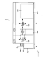
次に、上述した接合装置41の構成について説明する。接合装置41は、図8に示すように内部を密閉可能な処理容器190を有している。処理容器190のウェハ搬送領域60側の側面には、ウェハWU、WL、重合ウェハWTの搬入出口191が形成され、当該搬入出口191には開閉シャッタ192が設けられている。
処理容器190の内部は、内壁193によって、搬送領域T1と処理領域T2に区画されている。上述した搬入出口191は、搬送領域T1における処理容器190の側面に形成されている。また、内壁193にも、ウェハWU、WL、重合ウェハWTの搬入出口194が形成されている。
搬送領域T1のX方向正方向側には、ウェハWU、WL、重合ウェハWTを一時的に載置するためのトランジション200が設けられている。トランジション200は、例えば2段に形成され、ウェハWU、WL、重合ウェハWTのいずれか2つを同時に載置することができる。
搬送領域T1には、ウェハ搬送機構201が設けられている。ウェハ搬送機構201は、図8及び図9に示すように例えば鉛直方向、水平方向(Y方向、X方向)及び鉛直軸周りに移動自在な搬送アームを有している。そして、ウェハ搬送機構201は、搬送領域T1内、又は搬送領域T1と処理領域T2との間でウェハWU、WL、重合ウェハWTを搬送できる。
搬送領域T1のX方向負方向側には、ウェハWU、WLの水平方向の向きを調節する位置調節機構210が設けられている。位置調節機構210は、図10に示すように基台211と、ウェハWU、WLを吸着保持して回転させる保持部212と、ウェハWU、WLのノッチ部(図示せず)の位置を検出する検出部213と、を有している。そして、位置調節機構210では、保持部212に吸着保持されたウェハWU、WLを回転させながら検出部213でウェハWU、WLのノッチ部の位置を検出することで、当該ノッチ部の位置を調節してウェハWU、WLの水平方向の向きを調節している。
また、搬送領域T1には、上ウェハWUの表裏面を反転させる反転機構220が設けられている。反転機構220は、図11~図13に示すように上ウェハWUを保持する保持アーム221を有している。保持アーム221は、水平方向(図11及び図12中のY方向)に延伸している。また保持アーム221には、上ウェハWUを保持する保持部材222が例えば4箇所に設けられている。保持部材222は、図14に示すように保持アーム221に対して水平方向に移動可能に構成されている。また保持部材222の側面には、上ウェハWUの外周部を保持するための切り欠き223が形成されている。そして、これら保持部材222は、上ウェハWUを挟み込んで保持することができる。
保持アーム221は、図11~図13に示すように例えばモータなどを備えた第1の駆動部224に支持されている。この第1の駆動部224によって、保持アーム221は水平軸周りに回動自在である。また保持アーム221は、第1の駆動部224を中心に回動自在であると共に、水平方向(図11及び図12中のY方向)に移動自在である。第1の駆動部224の下方には、例えばモータなどを備えた第2の駆動部225が設けられている。この第2の駆動部225によって、第1の駆動部224は鉛直方向に延伸する支持柱226に沿って鉛直方向に移動できる。このように第1の駆動部224と第2の駆動部225によって、保持部材222に保持された上ウェハWUは、水平軸周りに回動できると共に鉛直方向及び水平方向に移動できる。また、保持部材222に保持された上ウェハWUは、第1の駆動部224を中心に回動して、位置調節機構210から後述する上チャック230との間を移動できる。
処理領域T2には、図8及び図9に示すように上ウェハWUを下面で吸着保持する第1の保持部材としての上チャック230と、下ウェハWLを上面で載置して吸着保持する第2の保持部材としての下チャック231とが設けられている。下チャック231は、上チャック230の下方に設けられ、上チャック230と対向配置可能に構成されている。すなわち、上チャック230に保持された上ウェハWUと下チャック231に保持された下ウェハWLは対向して配置可能となっている。
上チャック230は、図9に示すように処理容器190の天井面に設けられた支持部材232に支持されている。支持部材232は、上チャック230の上面外周部を支持している。下チャック231の下方には、シャフト233を介してチャック駆動部234が設けられている。このチャック駆動部234により、下チャック231は鉛直方向に昇降自在、且つ水平方向に移動自在になっている。チャック駆動部234によって、下チャック231は鉛直軸周りに回転自在である。また、下チャック231の下方には、下ウェハWLを下方から支持し昇降させるための昇降ピン(図示せず)が設けられている。昇降ピンは、下チャック231に形成された貫通孔(図示せず)を挿通し、下チャック231の上面から突出可能である。
上チャック230は、図15に示すように複数、例えば3つの領域230a、230b、230cに区画されている。これら領域230a、230b、230cは、図16に示すように上チャック230の中心部から外周部に向けてこの順で設けられている。そして、領域230aは平面視において円形状を有し、領域230b、230cは平面視において環状形状を有している。各領域230a、230b、230cには、図15に示すように上ウェハWUを吸着保持するための吸引管240a、240b、240cがそれぞれ独立して設けられている。各吸引管240a、240b、240cには、異なる真空ポンプ241a、241b、241cがそれぞれ接続されている。したがって、上チャック230は、各領域230a、230b、230c毎に上ウェハWUの真空引きを設定可能に構成されている。
なお、以下において、上述した3つの領域230a、230b、230cを、それぞれ第1の領域230a、第2の領域230b、第3の領域230cという場合がある。また、吸引管240a、240b、240cを、それぞれ第1の吸引管240a、第2の吸引管240b、第3の吸引管240cという場合がある。さらに、真空ポンプ241a、241b、241cを、それぞれ第1の真空ポンプ241a、第2の真空ポンプ241b、第3の真空ポンプ241cという場合がある。
上チャック230の内部には、上ウェハWUを加熱する第1の加熱機構242が設けられている。なお、第1の加熱機構242には、例えばヒータが用いられる。
上チャック230の中心部には、当該上チャック230を厚み方向に貫通する貫通孔243が形成されている。この上チャック230の中心部は、当該上チャック230に吸着保持される上ウェハWUの中心部に対応している。そして、貫通孔243には、後述する押動部材250の押動ピン251が挿通するようになっている。
上チャック230の上面には、上ウェハWUの中心部を押圧する押動部材250が設けられている。押動部材250は、シリンダ構造を有し、押動ピン251と当該押動ピン251が昇降する際のガイドとなる外筒252とを有している。押動ピン251は、例えばモータを内蔵した駆動部(図示せず)によって、貫通孔243を挿通して鉛直方向に昇降自在である。そして、押動部材250は、後述するウェハWU、WLの接合時に、上ウェハWUの中心部と下ウェハWLの中心部とを当接させて押圧することができる。
上チャック230には、下ウェハWLの表面WL1を撮像する上部撮像部材253が設けられている。上部撮像部材253には、例えば広角型のCCDカメラが用いられる。上部撮像部材253は、上チャック230上に設けられていてもよい。
下チャック231は、図17に示すように複数、例えば2つの領域231a、231bに区画されている。これら領域231a、231bは、下チャック231の中心部から外周部に向けてこの順で設けられている。そして、領域231aは平面視において円形状を有し、領域231bは平面視において環状形状を有している。各領域231a、231bには、図15に示すように下ウェハWLを吸着保持するための吸引管260a、260bがそれぞれ独立して設けられている。各吸引管260a、260bには、異なる真空ポンプ261a、261bがそれぞれ接続されている。したがって、下チャック231は、各領域231a、231b毎に下ウェハWLの真空引きを設定可能に構成されている。
下チャック231の内部には、下ウェハWLを加熱する第2の加熱機構262が設けられている。なお、第2の加熱機構262には、例えばヒータが用いられる。
下チャック231の外周部には、ウェハWU、WL、重合ウェハWTが当該下チャック231から飛び出したり、滑落するのを防止するストッパ部材263が設けられている。ストッパ部材263は、その頂部が少なくとも下チャック231上の重合ウェハWTよりも上方に位置するように鉛直方向に延伸している。また、ストッパ部材263は、図17に示すように下チャック231の外周部に複数個所、例えば5箇所に設けられている。
下チャック231には、図15に示すように上ウェハWUの表面WU1を撮像する下部撮像部材264が設けられている。下部撮像部材264には、例えば広角型のCCDカメラが用いられる。なお、下部撮像部材264は、下チャック231上に設けられていてもよい。
以上の接合システム1には、図1に示すように制御部300が設けられている。制御部300は、例えばコンピュータであり、プログラム格納部(図示せず)を有している。プログラム格納部には、接合システム1におけるウェハWU、WL、重合ウェハWTの処理を制御するプログラムが格納されている。また、プログラム格納部には、上述の各種処理装置や搬送装置などの駆動系の動作を制御して、接合システム1における後述のウェハ接合処理を実現させるためのプログラムも格納されている。なお、前記プログラムは、例えばコンピュータ読み取り可能なハードディスク(HD)、フレキシブルディスク(FD)、コンパクトディスク(CD)、マグネットオプティカルデスク(MO)、メモリーカードなどのコンピュータに読み取り可能な記憶媒体Hに記録されていたものであって、その記憶媒体Hから制御部300にインストールされたものであってもよい。
次に、以上のように構成された接合システム1を用いて行われるウェハWU、WLの接合処理方法について説明する。図18は、かかるウェハ接合処理の主な工程の例を示すフローチャートである。
先ず、複数枚の上ウェハWUを収容したカセットCU、複数枚の下ウェハWLを収容したカセットCL、及び空のカセットCTが、搬入出ステーション2の所定のカセット載置板11に載置される。その後、ウェハ搬送装置22によりカセットCU内の上ウェハWUが取り出され、処理ステーション3の第3の処理ブロックG3のトランジション装置50に搬送される。
次に上ウェハWUは、ウェハ搬送装置61によって第1の処理ブロックG1の表面改質装置30に搬送される。表面改質装置30に搬入された上ウェハWUは、ウェハ搬送装置61から載置台110の上面に受け渡され載置される。その後、ウェハ搬送装置61が表面改質装置30から退出し、ゲートバルブ102が閉じられる。なお、載置台110に載置された上ウェハWUは、温度調節機構112によって所定の温度、例えば25℃~30℃に維持される。
その後、吸気装置104を作動させ、吸気口103を介して処理容器100の内部の雰囲気が所定の真空度、例えば67Pa~333Pa(0.5Torr~2.5Torr)まで減圧される。そして、後述するように上ウェハWUを処理中、処理容器100内の雰囲気は上記所定の真空度に維持される。
その後、ガス供給管130から処理容器100内のプラズマ生成領域R1に向けて、酸素ガスが供給される。また、ラジアルラインスロットアンテナ120からプラズマ生成領域R1に向けて、例えば2.45GHzのマイクロ波が放射される。このマイクロ波の放射によって、プラズマ生成領域R1内において酸素ガスが励起されてプラズマ化され、例えば酸素ガスがイオン化する。このとき、下方に進行するマイクロ波は、イオン通過構造体140で反射し、プラズマ生成領域R1内に留まる。この結果、プラズマ生成領域R1内には、高密度のプラズマが生成される。
続いて、イオン通過構造体140において、電源145により一対の電極141、142に所定の電圧を印加する。そうすると、この一対の電極141、142によって、プラズマ生成領域R1で生成された酸素イオンのみが、イオン通過構造体140の開口部144を通過して処理領域R2に流入する。
このとき、制御部300によって、一対の電極141、142間に印加され電圧を制御することで、当該一対の電極141、142を通過する酸素イオンに付与されるエネルギーが制御される。この酸素イオンに付与されるエネルギーは、上ウェハWUの表面WU1のSiO2の二重結合を切断して単結合のSiOとするのに十分なエネルギーであって、当該表面WU1が損傷しないエネルギーに設定される。
またこのとき、電流計146によって一対の電極141、142間を流れる電流の電流値を測定する。この測定された電流値に基づいて、イオン通過構造体140を通過する酸素イオンの通過量が把握される。そして、制御部300では、把握された酸素イオンの通過量に基づいて、当該通過量が所定の値になるように、ガス供給管130からの酸素ガスの供給量や、一対の電極141、142間の電圧等、種々のパラメータを制御する。
その後、処理領域R2に導入された酸素イオンは、載置台110上の上ウェハWUの表面WU1に照射されて注入される。そして、照射された酸素イオンによって、表面WU1におけるSiO2の二重結合が切断されて単結合のSiOとなる。また、この表面WU1の改質には酸素イオンが用いられているため、上ウェハWUの表面WU1に照射された酸素イオン自体がSiOの結合に寄与する。こうして、上ウェハWUの表面WU1が改質される(図18の工程S1)。
このとき、イオン電流計111によって、上ウェハWUの表面WU1に照射された酸素イオンによって生じるイオン電流の電流値を測定する。この測定された電流値に基づいて、上ウェハWUの表面WU1に照射される酸素イオンの照射量が把握される。そして、制御部300では、把握された酸素イオンの照射量に基づいて、当該照射量が所定の値になるように、ガス供給管130からの酸素ガスの供給量や、一対の電極141、142間の電圧等、種々のパラメータを制御する。
次に上ウェハWUは、ウェハ搬送装置61によって第2の処理ブロックG2の表面親水化装置40に搬送される。表面親水化装置40に搬入された上ウェハWUは、ウェハ搬送装置61からスピンチャック160に受け渡され吸着保持される。
続いて、ノズルアーム171によって待機部175の純水ノズル173を上ウェハWUの中心部の上方まで移動させると共に、スクラブアーム172によってスクラブ洗浄具180を上ウェハWU上に移動させる。その後、スピンチャック160によって上ウェハWUを回転させながら、純水ノズル173から上ウェハWU上に純水を供給する。そうすると、表面改質装置30において改質された上ウェハWUの表面WU1に水酸基(シラノール基)が付着して当該表面WU1が親水化される。また、純水ノズル173からの純水とスクラブ洗浄具180によって、上ウェハWUの表面WU1が洗浄される(図18の工程S2)。なお、上ウェハWUの表面WU1に供給された純水のうち、一部の純水は上述したように表面WU1を親水化するため、すなわち後述するように、ウェハWU、WLを接合するために用いられるが、残りの余剰分の純水は上ウェハWUの表面WU1に残存している。
次に上ウェハWUは、ウェハ搬送装置61によって第2の処理ブロックG2の接合装置41に搬送される。接合装置41に搬入された上ウェハWUは、トランジション200を介してウェハ搬送機構201により位置調節機構210に搬送される。そして位置調節機構210によって、上ウェハWUの水平方向の向きが調節される(図18の工程S3)。
その後、位置調節機構210から反転機構220の保持アーム221に上ウェハWUが受け渡される。続いて搬送領域T1において、保持アーム221を反転させることにより、上ウェハWUの表裏面が反転される(図18の工程S4)。すなわち、上ウェハWUの表面WU1が下方に向けられる。
その後、反転機構220の保持アーム221が、第1の駆動部224を中心に回動して上チャック230の下方に移動する。そして、反転機構220から上チャック230に上ウェハWUが受け渡される。上ウェハWUは、上チャック230にその裏面WU2が吸着保持される(図18の工程S5)。このとき、すべての真空ポンプ241a、241b、241cを作動させ、上チャック230のすべての領域230a、230b、230cにおいて、上ウェハWUを真空引きしている。上ウェハWUは、後述する下ウェハWLが接合装置41に搬送されるまで上チャック230で待機する。
上ウェハWUに上述した工程S1~S5の処理が行われている間、当該上ウェハWUに続いて下ウェハWLの処理が行われる。先ず、ウェハ搬送装置22によりカセットCL内の下ウェハWLが取り出され、処理ステーション3のトランジション装置50に搬送される。
次に下ウェハWLは、ウェハ搬送装置61によって表面改質装置30に搬送され、下ウェハWLの表面WL1が改質される(図18の工程S6)。なお、工程S6における下ウェハWLの表面WL1の改質は、上述した工程S1と同様である。
その後、下ウェハWLは、ウェハ搬送装置61によって表面親水化装置40に搬送され、下ウェハWLの表面WL1が親水化される共に当該表面WL1が洗浄される(図18の工程S7)。なお、工程S7における下ウェハWLの表面WL1の親水化及び洗浄は、上述した工程S2と同様であるので詳細な説明を省略する。また、下ウェハWLの表面WL1に供給された純水のうち、一部の純水は表面WL1を親水化するため、すなわち後述するように、ウェハWU、WLを接合するために用いられるが、残りの余剰分の純水は下ウェハWLの表面WL1に残存している。
その後、下ウェハWLは、ウェハ搬送装置61によって接合装置41に搬送される。接合装置41に搬入された下ウェハWLは、トランジション200を介してウェハ搬送機構201により位置調節機構210に搬送される。そして位置調節機構210によって、下ウェハWLの水平方向の向きが調節される(図18の工程S8)。
その後、下ウェハWLは、ウェハ搬送機構201によって下チャック231に搬送され、下チャック231に吸着保持される(図18の工程S9)。このとき、すべての真空ポンプ261a、261bを作動させ、下チャック231のすべての領域231a、231bにおいて、下ウェハWLを真空引きしている。そして、下ウェハWLの表面WL1が上方を向くように、当該下ウェハWLの裏面WL2が下チャック231に吸着保持される。
次に、上チャック230に保持された上ウェハWUと下チャック231に保持された下ウェハWLとの水平方向の位置調節を行う。図19に示すように下ウェハWLの表面WL1には予め定められた複数、例えば4点以上の基準点Aが形成され、同様に上ウェハWUの表面WU1には予め定められた複数、例えば4点以上の基準点Bが形成されている。これら基準点A、Bとしては、例えばウェハWL、WU上に形成された所定のパターンがそれぞれ用いられる。そして、上部撮像部材253を水平方向に移動させ、下ウェハWLの表面WL1が撮像される。また、下部撮像部材264を水平方向に移動させ、上ウェハWUの表面WU1が撮像される。その後、上部撮像部材253が撮像した画像に表示される下ウェハWLの基準点Aの位置と、下部撮像部材264が撮像した画像に表示される上ウェハWUの基準点Bの位置とが合致するように、下チャック231によって下ウェハWLの水平方向の位置(水平方向の向きを含む)が調節される。すなわち、チャック駆動部234によって、下チャック231を水平方向に移動させて、下ウェハWLの水平方向の位置が調節される。こうして上ウェハWUと下ウェハWLとの水平方向の位置が調節される(図18の工程S10)。なお、上部撮像部材256と下部撮像部材264を移動させる代わりに、下チャック231を移動させてもよい。
なお、ウェハWU、WLの水平方向きは、工程S3、S8において位置調節機構210によって調節されているが、工程S10において微調節が行われる。また、本実施の形態の工程S10では、基準点A、Bとして、ウェハWL、WU上に形成された所定のパターンを用いていたが、その他の基準点を用いることもできる。例えばウェハWL、WUの外周部とノッチ部を基準点として用いることができる。
その後、チャック駆動部234によって、図20に示すように下チャック231を上昇させ、下ウェハWLを所定の位置に配置する。このとき、下ウェハWLの表面WL1と上ウェハWUの表面WU1との間の間隔が所定の距離、例えば80μm~200μmになるように下ウェハWLを配置する。こうして上ウェハWUと下ウェハWLとの鉛直方向の位置が調節される(図18の工程S11)。なお、工程S5~工程S11において、上チャック230のすべての領域230a、230b、230cにおいて、上ウェハWUを真空引きしている。同様に工程S9~工程S11において、下チャック231のすべての領域231a、231bにおいて、下ウェハWLを真空引きしている。
このように工程S10、S11において上ウェハWUと下ウェハWLとの水平方向と鉛直方向の位置が調節されている間、上ウェハWUは第1の加熱機構242によって所定の温度に加熱され、下ウェハWLは第2の加熱機構262によって所定の温度に加熱される。本実施の形態では、上ウェハWUと下ウェハWLが加熱される所定の温度はそれぞれ例えば50℃~100℃であって、上ウェハWUと下ウェハWLは同じ温度に加熱される。この所定の温度50℃~100℃は、発明者らが鋭意検討した結果に見出した温度であり、後述するように余剰分の純水を除去できる温度である。なお、余剰分の純水を除去できる温度であれば、所定の温度は本実施の形態に限定されず、種々の温度を取り得る。
ここで工程S2、S7においてウェハWU、WLに供給された純水のうち、上述したように、上ウェハWUの表面WU1と下ウェハWLの表面WL1には、それぞれ余剰分の純水が残存している。そこで、工程S10、S11において上述のように上ウェハWUと下ウェハWLをそれぞれ所定の温度に加熱することによって、この余剰分の純水を除去することができる。そして、上ウェハWUと下ウェハWLを所定時間加熱して余剰分の純水がすべて除去されると、上ウェハWUと下ウェハWLの加熱が停止される。
その後、第1の真空ポンプ241aの作動を停止して、図21に示すように第1の領域230aにおける第1の吸引管240aからの上ウェハWUの真空引きを停止する。このとき、第2の領域230bと第3の領域230cでは、上ウェハWUが真空引きされて吸着保持されている。その後、押動部材250の押動ピン251を下降させることによって、上ウェハWUの中心部を押圧しながら当該上ウェハWUを下降させる。このとき、押動ピン251には、上ウェハWUがない状態で当該押動ピン251が70μm移動するような荷重、例えば200gがかけられる。そして、押動部材250によって、上ウェハWUの中心部と下ウェハWLの中心部を当接させて押圧する(図18の工程S12)。
そうすると、押圧された上ウェハWUの中心部と下ウェハWLの中心部との間で接合が開始する(図21中の太線部)。すなわち、上ウェハWUの表面WU1と下ウェハWLの表面WL1はそれぞれ工程S1、S6において改質されているため、先ず、表面WU1、WL1間にファンデルワールス力(分子間力)が生じ、当該表面WU1、WL1同士が接合される。さらに、上ウェハWUの表面WU1と下ウェハWLの表面WL1はそれぞれ工程S2、S7において親水化されているため、表面WU1、WL1間の親水基が水素結合し(分子間力)、表面WU1、WL1同士が強固に接合される。
その後、図22に示すように押動部材250によって上ウェハWUの中心部と下ウェハWLの中心部を押圧した状態で、第2の真空ポンプ241bの作動を停止して、第2の領域230bにおける第2の吸引管240bからの上ウェハWUの真空引きを停止する。そうすると、第2の領域230bに保持されていた上ウェハWUが下ウェハWL上に落下する。さらにその後、第3の真空ポンプ241cの作動を停止して、第3の領域230cにおける第3の吸引管240cからの上ウェハWUの真空引きを停止する。このように上ウェハWUの中心部から外周部に向けて、上ウェハWUの真空引きを停止し、上ウェハWUが下ウェハWL上に順次落下して当接する。そして、上述した表面WU1、WL1間のファンデルワールス力と水素結合による接合が順次拡がる。こうして、図23に示すように上ウェハWUの表面WU1と下ウェハWLの表面WL1が全面で当接し、上ウェハWUと下ウェハWLが接合される(図18の工程S13)。
この工程S13では、ウェハWU、WLの表面WU1、WL1の拡散する接合、いわゆるボンディングウェーブが生じるが、工程S10、S11において上ウェハWUと下ウェハWLを加熱することにより余剰分の純水が除去されているので、従来のように余剰分の純水がウェハWU、WLの外周部に拡散することはない。
その後、図24に示すように押動部材250を上チャック230まで上昇させる。また、下チャック231において吸引管260a、260bからの下ウェハWLの真空引きを停止して、下チャック231による下ウェハWLの吸着保持を停止する。
上ウェハWUと下ウェハWLが接合された重合ウェハWTは、ウェハ搬送装置61によってトランジション装置51に搬送され、その後搬入出ステーション2のウェハ搬送装置22によって所定のカセット載置板11のカセットCTに搬送される。こうして、一連のウェハWU、WLの接合処理が終了する。
以上の実施の形態によれば、工程S10、S11において、上チャック230に保持された上ウェハWUと、下チャック231に保持された下ウェハWLを所定の温度に加熱する。かかる加熱によって、ウェハWU、WLの表面WU1、WL1上の余剰分の純水を、当該表面WU1、WL1から除去することができる。したがって、従来のように余剰分の純水がウェハWU、WLの外周部に拡散することがなく、ウェハWU、WL間の外周部に気泡(Edge Void)が発生するのを抑制することができる。そして、ウェハWU、WL同士をファンデルワールス力と水素結合(分子間力)によって適切に接合することができる。
また、工程S10、S11において上チャック230に保持された上ウェハWUと、下チャック231に保持された下ウェハWLとを水平方向と鉛直方向に位置調節しながら、ウェハWU、WLの加熱が行われるので、当該ウェハWU、WLの加熱を効率よく行うことができる。したがって、ウェハ接合処理のスループットを向上させることができる。なお、ウェハWU、WLの加熱は、工程S10又は工程S11のいずれか一方の工程において行ってもよい。また、ウェハWU、WLの加熱は、工程S5、S9において上ウェハWUが上チャック230に保持され、下ウェハWLが下チャック231に保持される際に行ってもよい。
また、接合システム1は、接合装置41に加えて、ウェハWU、WLの表面WU1、WL1を改質する表面改質装置30と、ウェハWU、WLの表面WU1、WL1を親水化すると共に当該表面WU1、WL1を洗浄する表面親水化装置40も備えているので、一のシステム内でウェハWU、WLの接合を効率よく行うことができる。したがって、ウェハ接合処理のスループットをより向上させることができる。
以上の実施の形態では、第1の加熱機構242と第2の加熱機構262によって上ウェハWUと下ウェハWLを両方加熱していたが、上ウェハWU又は下ウェハWLのいずれか一方のみを加熱してもよい。そして、第1の加熱機構242又は第2の加熱機構262のいずれか一方を省略してもよい。かかる場合、例えば上ウェハWUのみを加熱して所定の時間、例えば30秒経過させることで、上ウェハWUの熱が下ウェハWLに伝達し、下ウェハWLも同一の温度に加熱される。また下ウェハWLのみを加熱する場合も同様に、所定の時間経過後、上ウェハWUも同一の温度に加熱される。いずれの場合でも、上ウェハWUと下ウェハWLの温度が所定の温度に加熱されるので、ウェハWU、WL間の外周部に気泡が発生するのが抑制され、ウェハWU、WL同士を適切に接合することができる。なお、上ウェハWU又は下ウェハWLのいずれか一方を加熱する時間は、ウェハ接合処理のスループットに影響のない範囲で設定される。
以上の実施の形態では、第1の加熱機構242と第2の加熱機構262によって上ウェハWUと下ウェハWLを同一の温度に加熱していたが、上ウェハWUと下ウェハWLを異なる温度に加熱してもよい。例えば工程S10、S11において、上ウェハWUの加熱温度と下ウェハWLの加熱温度の温度差が、例えば10℃~20℃となるように、上ウェハWUと下ウェハWLを加熱する。
ここで、上チャック230の表面又は下チャック231の表面に凹凸が存在したり、或いは上チャック230の表面又は下チャック231の表面にパーティクル等が存在して、当該上チャック230の表面又は下チャック231の表面が平坦でない場合がある。かかる場合、上ウェハWUと下ウェハWLを接合すると、接合界面の残留応力により、接合された重合ウェハWTに鉛直方向の歪み(Distortion)が生じる。
本実施の形態では、上ウェハWUと下ウェハWLが異なる温度に加熱されるので、上チャック230の表面と下チャック231の表面の状態に合わせて、上ウェハWUと下ウェハWLをそれぞれ異なる形状に変形させることができる。例えば上ウェハWUを下ウェハWLより高い温度で加熱すれば、上ウェハWUを下ウェハWLより膨張させることができる。同様に下ウェハWLを上ウェハWUより高い温度で加熱すれば、下ウェハWLを上ウェハWUより膨張させることができる。このように上ウェハWUと下ウェハWLの反り状態を、上チャック230の表面と下チャック231の表面の状態に合わせることにより、重合ウェハWTに鉛直方向の歪みを抑制することができる。したがって、その後工程S12、S13において、上ウェハWUと下ウェハWLを適切に接合することができる。
なお、上ウェハWUの加熱温度と下ウェハWLの加熱温度の温度差10℃~20℃は、発明者らが鋭意検討した結果に見出した温度であり、重合ウェハWTに鉛直方向の歪みを十分に抑制できる温度である。
以上の実施の形態で述べたとおり、少なくとも上ウェハWU又は下ウェハWLを所定の温度50℃~100℃に加熱すると、ウェハWU、WL間の外周部に気泡(Edge Void)が発生するのを抑制することができる。このようにEdge Voidを抑制することは、例えば表面にSiO2からなる絶縁膜が形成されたSOI(Silicon On Insulater)ウェハに有用である。また、上ウェハWUの加熱温度と下ウェハWLの加熱温度の温度差を10℃~20℃にすると、重合ウェハWTの鉛直方向の歪み(Distortion)を抑制することができる。このようにDistortionを抑制することは、例えばCMOS(Complementary Metal Oxide Semiconductor)センサのウェハのウェハやBSIモデル(Back Side Illumination)のウェハに有用である。さらに、Edge VoidとDistortionの両方の改善が要求される場合には、少なくとも上ウェハWU又は下ウェハWLを所定の温度50℃~100℃に加熱しつつ、上ウェハWUの加熱温度と下ウェハWLの加熱温度の温度差を10℃~20℃にすればよい。
以上の実施の形態では、工程S10、S11において、上チャック230の第1の加熱機構242は上ウェハWUをウェハ面内で均一な温度に加熱していたが、例えば上チャック230の領域230a、230b、230c毎に異なる温度で上ウェハWUを加熱してもよい。同様に下チャック231の第2の加熱機構262は下ウェハWLをウェハ面内で均一な温度に加熱していたが、例えば下チャック231の領域231a、231b毎に異なる温度で下ウェハWLを加熱してもよい。かかる場合、上チャック230の表面と下チャック231の表面の状態に合わせて、上ウェハWUと下ウェハWLをより適切な形状に変形させることができる。したがって、上ウェハWUと下ウェハWLをより適切に接合することができる。なお、上チャック230と下チャック231を区画する数や区画される領域の配置は、本実施の形態に限定されず、任意に設定することができる。
以上の実施の形態では、チャック駆動部234によって下チャック231が鉛直方向に昇降自在且つ水平方向に移動自在になっていたが、上チャック230を鉛直方向に昇降自在にし、あるいは水平方向に移動自在に構成してもよい。また、上チャック230と下チャック231の両方が、鉛直方向に昇降自在且つ水平方向に移動自在に構成されていてもよい。
以上の実施の形態の接合システム1において、接合装置41でウェハWU、WLを接合した後、さらに接合された重合ウェハWTを所定の温度で加熱してもよい。重合ウェハWTにかかる加熱処理を行うことで、接合界面をより強固に結合させることができる。
以上、添付図面を参照しながら本発明の好適な実施の形態について説明したが、本発明はかかる例に限定されない。当業者であれば、特許請求の範囲に記載された思想の範疇内において、各種の変更例または修正例に想到し得ることは明らかであり、それらについても当然に本発明の技術的範囲に属するものと了解される。本発明はこの例に限らず種々の態様を採りうるものである。本発明は、基板がウェハ以外のFPD(フラットパネルディスプレイ)、フォトマスク用のマスクレチクルなどの他の基板である場合にも適用できる。
1 接合システム
2 搬入出ステーション
3 処理ステーション
30 表面改質装置
40 表面親水化装置
41 接合装置
60 ウェハ搬送領域
230 上チャック
231 下チャック
242 第1の加熱機構
262 第2の加熱機構
300 制御部
WU 上ウェハ
WL 下ウェハ
WT 重合ウェハ
2 搬入出ステーション
3 処理ステーション
30 表面改質装置
40 表面親水化装置
41 接合装置
60 ウェハ搬送領域
230 上チャック
231 下チャック
242 第1の加熱機構
262 第2の加熱機構
300 制御部
WU 上ウェハ
WL 下ウェハ
WT 重合ウェハ
Claims (11)
- 基板同士を分子間力によって接合する接合装置であって、
下面に第1の基板を真空引きして吸着保持する第1の保持部材と、
前記第1の保持部材の下方に設けられ、上面に第2の基板を真空引きして吸着保持する第2の保持部材と、有し、
少なくとも前記第1の保持部材又は前記第2の保持部材は、少なくとも第1の基板又は第2の基板を所定の温度に加熱する加熱機構を有する。 - 請求項1に記載の接合装置において、
前記第1の保持部材は第1の基板を加熱する第1の加熱機構を有し、
前記第2の保持部材は第2の基板を加熱する第2の加熱機構を有し、
前記第1の加熱機構と前記第2の加熱機構には、前記第1の加熱機構による第1の基板の加熱温度と、前記第2の加熱機構による第2の基板の加熱温度とを異なる温度に制御する制御部が設けられている。 - 請求項2に記載の接合装置において、
前記第1の基板の加熱温度と前記第2の基板の加熱温度の温度差は、10℃~20℃である。 - 請求項1に記載の接合装置において、
前記第1の保持部材は第1の基板を加熱する第1の加熱機構を有し、
前記第2の保持部材は第2の基板を加熱する第2の加熱機構を有し、
前記第1の加熱機構と前記第2の加熱機構には、前記第1の保持部材に保持された第1の基板と、前記第2の保持部材に保持された第2の基板との、少なくとも鉛直方向又は水平方向の位置調節をしながら、第1の基板と第2の基板を加熱するように制御する制御部が設けられている。 - 請求項1に記載の接合装置において、
前記所定の温度は、50℃~100℃である。 - 基板同士を分子間力によって接合する接合装置を備えた接合システムであって、
前記接合装置を備えた処理ステーションと、
第1の基板、第2の基板又は第1の基板と第2の基板が接合された重合基板をそれぞれ複数保有可能で、且つ前記処理ステーションに対して第1の基板、第2の基板又は重合基板を搬入出する搬入出ステーションと、を備え、
前記処理ステーションは、
第1の基板又は第2の基板の接合される表面を改質する表面改質装置と、
前記表面改質装置で改質された第1の基板又は第2の基板の表面を親水化する表面親水化装置と、
前記表面改質装置、前記表面親水化装置及び前記接合装置に対して、第1の基板、第2の基板又は重合基板を搬送するための搬送領域と、を有し、
前記接合装置は、
下面に第1の基板を真空引きして吸着保持する第1の保持部材と、
前記第1の保持部材の下方に設けられ、上面に第2の基板を真空引きして吸着保持する第2の保持部材と、有し、
少なくとも前記第1の保持部材又は前記第2の保持部材は、少なくとも第1の基板又は第2の基板を所定の温度に加熱する加熱機構を有し。
前記接合装置では、前記表面親水化装置で表面が親水化された第1の基板と第2の基板を接合することを特徴とする、接合システム。 - 基板同士を分子間力によって接合する接合方法であって、
第1の保持部材の下面に吸着保持された第1の基板と、前記第1の保持部材の下方に設けられた第2の保持部材の上面に吸着保持された第2の基板とを接合する際に、少なくとも第1の基板又は第2の基板を所定の温度に加熱する。 - 請求項7に記載の接合方法において、
前記第1の保持部材に保持された第1の基板と前記第2の保持部材に保持された第2の基板を接合する際、第1の基板と第2の基板を共に加熱し、且つ第1の基板と第2の基板を異なる温度に加熱する。 - 請求項8に記載の接合方法において、
前記第1の基板の加熱温度と前記第2の基板の加熱温度の温度差は、10℃~20℃である。 - 請求項7に記載の接合方法において、
前記第1の保持部材に保持された第1の基板と、前記第2の保持部材に保持された第2の基板との少なくとも鉛直方向又は水平方向の位置調節をしながら、第1の基板と第2の基板を共に加熱する。 - 請求項7に記載の接合方法において、
前記所定の温度は、50℃~100℃である。
Applications Claiming Priority (2)
| Application Number | Priority Date | Filing Date | Title |
|---|---|---|---|
| JP2012-058231 | 2012-03-15 | ||
| JP2012058231A JP5626736B2 (ja) | 2012-03-15 | 2012-03-15 | 接合装置、接合システム、接合方法、プログラム及びコンピュータ記憶媒体 |
Publications (1)
| Publication Number | Publication Date |
|---|---|
| WO2013137002A1 true WO2013137002A1 (ja) | 2013-09-19 |
Family
ID=49160918
Family Applications (1)
| Application Number | Title | Priority Date | Filing Date |
|---|---|---|---|
| PCT/JP2013/055397 WO2013137002A1 (ja) | 2012-03-15 | 2013-02-28 | 接合装置、接合システム及び接合方法 |
Country Status (3)
| Country | Link |
|---|---|
| JP (1) | JP5626736B2 (ja) |
| TW (1) | TWI536465B (ja) |
| WO (1) | WO2013137002A1 (ja) |
Cited By (6)
| Publication number | Priority date | Publication date | Assignee | Title |
|---|---|---|---|---|
| US10755929B2 (en) | 2016-02-16 | 2020-08-25 | Ev Group E. Thallner Gmbh | Method and device for bonding of substrates |
| CN112038220A (zh) * | 2020-08-31 | 2020-12-04 | 上海华力集成电路制造有限公司 | 晶圆键合工艺中改善晶圆边缘形变的方法 |
| JPWO2021006091A1 (ja) * | 2019-07-10 | 2021-01-14 | ||
| US11315813B2 (en) | 2015-04-10 | 2022-04-26 | Ev Group E. Thallner Gmbh | Substrate holder and method for bonding two substrates |
| EP3433875B1 (de) | 2016-03-22 | 2022-05-04 | EV Group E. Thallner GmbH | Verfahren zum bonden von substraten |
| US20220148978A1 (en) * | 2014-12-10 | 2022-05-12 | Nikon Corporation | Apparatus for stacking substrates and method for the same |
Families Citing this family (9)
| Publication number | Priority date | Publication date | Assignee | Title |
|---|---|---|---|---|
| JP6244188B2 (ja) * | 2013-11-27 | 2017-12-06 | 東京エレクトロン株式会社 | 接合装置、接合方法および接合システム |
| JP6177739B2 (ja) * | 2014-08-07 | 2017-08-09 | 東京エレクトロン株式会社 | 接合装置、接合システム、接合方法、プログラム及びコンピュータ記憶媒体 |
| JP6727069B2 (ja) * | 2016-08-09 | 2020-07-22 | 東京エレクトロン株式会社 | 接合装置および接合システム |
| US10497667B2 (en) * | 2017-09-26 | 2019-12-03 | Taiwan Semiconductor Manufacturing Co., Ltd. | Apparatus for bond wave propagation control |
| US11094575B2 (en) | 2019-06-03 | 2021-08-17 | Taiwan Semiconductor Manufacturing Company, Ltd. | Simultaneous bonding approach for high quality wafer stacking applications |
| JP7014850B2 (ja) * | 2020-04-28 | 2022-02-01 | エーファウ・グループ・エー・タルナー・ゲーエムベーハー | 2つの基板をボンディングするための基板ホルダおよび方法 |
| JP6861872B2 (ja) * | 2020-05-01 | 2021-04-21 | 東京エレクトロン株式会社 | 接合装置および接合システム |
| TWI799989B (zh) * | 2021-09-13 | 2023-04-21 | 日商雅馬哈智能機器控股股份有限公司 | 表面處理裝置及半導體裝置的製造裝置 |
| KR102346975B1 (ko) * | 2021-10-18 | 2022-01-05 | 에이치비솔루션㈜ | 박형의 디스플레이 패널 이송 및 코팅 장치 |
Citations (2)
| Publication number | Priority date | Publication date | Assignee | Title |
|---|---|---|---|---|
| JP2006339363A (ja) * | 2005-06-01 | 2006-12-14 | Bondtech Inc | 表面活性化方法および表面活性化装置 |
| JP2007103225A (ja) * | 2005-10-06 | 2007-04-19 | Nikon Corp | ウェハ搬送装置、ウェハ積層体搬送装置及び積層型半導体装置製造方法 |
-
2012
- 2012-03-15 JP JP2012058231A patent/JP5626736B2/ja active Active
-
2013
- 2013-02-28 WO PCT/JP2013/055397 patent/WO2013137002A1/ja active Application Filing
- 2013-03-05 TW TW102107649A patent/TWI536465B/zh active
Patent Citations (2)
| Publication number | Priority date | Publication date | Assignee | Title |
|---|---|---|---|---|
| JP2006339363A (ja) * | 2005-06-01 | 2006-12-14 | Bondtech Inc | 表面活性化方法および表面活性化装置 |
| JP2007103225A (ja) * | 2005-10-06 | 2007-04-19 | Nikon Corp | ウェハ搬送装置、ウェハ積層体搬送装置及び積層型半導体装置製造方法 |
Cited By (10)
| Publication number | Priority date | Publication date | Assignee | Title |
|---|---|---|---|---|
| US20220148978A1 (en) * | 2014-12-10 | 2022-05-12 | Nikon Corporation | Apparatus for stacking substrates and method for the same |
| US11315813B2 (en) | 2015-04-10 | 2022-04-26 | Ev Group E. Thallner Gmbh | Substrate holder and method for bonding two substrates |
| US10755929B2 (en) | 2016-02-16 | 2020-08-25 | Ev Group E. Thallner Gmbh | Method and device for bonding of substrates |
| US10755930B2 (en) | 2016-02-16 | 2020-08-25 | Ev Group E. Thallner Gmbh | Method and device for bonding of substrates |
| US11101132B2 (en) | 2016-02-16 | 2021-08-24 | Ev Group E. Thallner Gmbh | Method and device for bonding of substrates |
| US11742205B2 (en) | 2016-02-16 | 2023-08-29 | Ev Group E. Thallner Gmbh | Method and device for bonding of substrates |
| EP3433875B1 (de) | 2016-03-22 | 2022-05-04 | EV Group E. Thallner GmbH | Verfahren zum bonden von substraten |
| JPWO2021006091A1 (ja) * | 2019-07-10 | 2021-01-14 | ||
| JP7229353B2 (ja) | 2019-07-10 | 2023-02-27 | 東京エレクトロン株式会社 | 分離装置及び分離方法 |
| CN112038220A (zh) * | 2020-08-31 | 2020-12-04 | 上海华力集成电路制造有限公司 | 晶圆键合工艺中改善晶圆边缘形变的方法 |
Also Published As
| Publication number | Publication date |
|---|---|
| JP5626736B2 (ja) | 2014-11-19 |
| JP2013191789A (ja) | 2013-09-26 |
| TW201401383A (zh) | 2014-01-01 |
| TWI536465B (zh) | 2016-06-01 |
Similar Documents
| Publication | Publication Date | Title |
|---|---|---|
| JP5626736B2 (ja) | 接合装置、接合システム、接合方法、プログラム及びコンピュータ記憶媒体 | |
| JP5521066B1 (ja) | 接合装置及び接合システム | |
| WO2012114826A1 (ja) | 接合装置、接合システム及び接合方法 | |
| KR102146633B1 (ko) | 접합 장치 및 접합 시스템 | |
| JP5606429B2 (ja) | 接合方法、プログラム、コンピュータ記憶媒体、接合装置及び接合システム | |
| JP5389847B2 (ja) | 接合方法、プログラム、コンピュータ記憶媒体、接合装置及び接合システム | |
| JP5705180B2 (ja) | 検査装置、接合システム、検査方法、プログラム及びコンピュータ記憶媒体 | |
| WO2012121046A1 (ja) | 接合装置、接合システム及び接合方法 | |
| JP2013120902A (ja) | 接合方法、プログラム、コンピュータ記憶媒体、接合装置及び接合システム | |
| JP5352609B2 (ja) | 接合方法、プログラム、コンピュータ記憶媒体、接合装置及び接合システム | |
| JP5411177B2 (ja) | 接合装置、接合システム、接合方法、プログラム及びコンピュータ記憶媒体 | |
| JP2014138136A (ja) | 接合方法、プログラム、コンピュータ記憶媒体及び接合システム | |
| WO2013002012A1 (ja) | 表面改質装置、接合システム及び表面改質方法 | |
| JP6813816B2 (ja) | 接合システムおよび接合方法 | |
| JP5674731B2 (ja) | 検査装置、接合システム、検査方法、プログラム及びコンピュータ記憶媒体 | |
| JP2014150266A (ja) | 接合装置及び接合システム | |
| JP5531123B1 (ja) | 接合装置及び接合システム | |
| JP2017073455A (ja) | 接合システム |
Legal Events
| Date | Code | Title | Description |
|---|---|---|---|
| 121 | Ep: the epo has been informed by wipo that ep was designated in this application |
Ref document number: 13761594 Country of ref document: EP Kind code of ref document: A1 |
|
| NENP | Non-entry into the national phase |
Ref country code: DE |
|
| 122 | Ep: pct application non-entry in european phase |
Ref document number: 13761594 Country of ref document: EP Kind code of ref document: A1 |