WO2013136997A1 - プログラム制御装置、マザーボードおよび情報処理装置 - Google Patents
プログラム制御装置、マザーボードおよび情報処理装置 Download PDFInfo
- Publication number
- WO2013136997A1 WO2013136997A1 PCT/JP2013/055309 JP2013055309W WO2013136997A1 WO 2013136997 A1 WO2013136997 A1 WO 2013136997A1 JP 2013055309 W JP2013055309 W JP 2013055309W WO 2013136997 A1 WO2013136997 A1 WO 2013136997A1
- Authority
- WO
- WIPO (PCT)
- Prior art keywords
- bios
- control program
- program
- control
- storage unit
- Prior art date
- Legal status (The legal status is an assumption and is not a legal conclusion. Google has not performed a legal analysis and makes no representation as to the accuracy of the status listed.)
- Ceased
Links
Images



Classifications
-
- G—PHYSICS
- G06—COMPUTING OR CALCULATING; COUNTING
- G06F—ELECTRIC DIGITAL DATA PROCESSING
- G06F9/00—Arrangements for program control, e.g. control units
- G06F9/06—Arrangements for program control, e.g. control units using stored programs, i.e. using an internal store of processing equipment to receive or retain programs
- G06F9/44—Arrangements for executing specific programs
- G06F9/4401—Bootstrapping
Definitions
- the present invention relates to a program control device, and more particularly to a control device that selects and operates one of a plurality of control programs.
- the present invention also relates to a mother board and an information processing apparatus provided with such a program control device.
- BIOS Basic Memory
- BIOS Basic Memory
- the conventional apparatus has a problem that, for example, when the selection unit is switched from the first BIOS to the second BIOS, the setting information in the first BIOS is not inherited to the second BIOS. For this reason, the user is forced to start up the BIOS setup screen of the computer and set the setting information for the second BIOS.
- This problem is not limited to a device that selects and starts any BIOS among a plurality of BIOSes, and generally occurs in a device that selects and operates one of a plurality of control programs. obtain.
- an object of the present invention is a program control apparatus that selects and operates any one of a plurality of control programs, and the user has to set setting information even when any control program is activated. It is to provide what can be omitted.
- Another object of the present invention is to provide a mother board and an information processing apparatus provided with such a program control device.
- a program control apparatus of the present invention provides: A program control device for selecting and operating any one of a plurality of control programs including at least a first control program and a second control program, A first storage unit for storing a program body of the first control program; A second storage unit for storing the program body of the second control program; A third storage unit for storing common setting information for the first and second control programs; A control program selection unit for selecting one of the first control program and the second control program; The program body of the first control program or the second control program selected by the control program selection unit refers to common setting information stored in the third storage unit. .
- control program is a concept including a program main body for executing processing and setting information referred to by the program main body.
- the setting information is information set in the variable setting portion of the control program, and CPU (Central Processing Unit) or chipset operation setting data, various timer setting values, OS (Operating System); This includes information such as the type of device that contains the operating system.
- CPU Central Processing Unit
- OS Operating System
- control programs included in this program control device is not limited to the first and second control programs, and may be three or more.
- the program body of the first control program is a common setting stored in the third storage unit.
- Browse information As a result, when the first control program starts normally, the user does not need to set various setting information for the first control program.
- the control program selection unit selects the second control program instead of the first control program, the second control program is selected.
- the program body of the program refers to the common setting information stored in the third storage unit.
- a control program priority storage unit for storing a startup priority between the first control program and the second control program;
- the control program selection unit A primary selection unit that selects one of the first control program and the second control program according to the activation priority stored in the control program priority storage unit; And a secondary selection unit that selects another control program when the control program selected by the primary selection unit is not activated.
- control program selection unit is configured such that the first selection program and the first control program according to the activation priority stored in the control program priority storage unit are firstly selected by the primary selection unit. Either one of the second control programs is selected.
- the control program selection unit is separated by the secondary selection unit according to the activation priority stored in the control program priority storage unit. Select the control program. In this way, the control program selection unit can select either the first control program or the second control program.
- the activation priority stored in the control program priority storage unit is ranked first for the activated control program.
- an activation priority changing unit for changing to the above.
- the activation priority changing unit stores the activated control program in the control program priority storage unit.
- the startup priority is changed to 1st place.
- the activated control program is first selected by the primary selection unit of the control program selection unit.
- the activated control program is expected to be normally activated at the next activation. Therefore, at the next start-up, quick start-up can be performed without trying to start the control program many times.
- the control program selection unit When a control program is selected by the primary selection unit or the secondary selection unit, a timer for counting the time since the control program is selected is provided, If the start of the selected control program is not completed even when the time counted by the timer reaches a certain time, it is determined that the selected control program is not started.
- the control program selection unit when the control program is selected by the primary selection unit or the secondary selection unit, the control program selection unit counts the time since the control program is selected. A timer is provided. Then, if the selected control program is not started even if the time counted by the timer reaches a certain time, it is determined that the selected control program is not started. Therefore, it can be reliably determined whether or not the selected control program is activated.
- the third storage unit includes the first control program and the second control program separately from the activation priority stored in the control program priority storage unit. It is characterized by memorizing the activation priority between.
- the third storage unit includes the first control program, the second control program, and the like.
- the activation priority during is stored. Therefore, the control program priority storage unit and the third storage unit can store the activation priority of the control program in a redundant manner. Therefore, even if the stored contents of either the control program priority storage unit or the third storage unit are damaged, either the first control program or the second control program is selected. can do.
- the program control device of the present invention provides: A program control device for selecting and operating any one of a plurality of control programs including at least a first control program and a second control program, A first storage unit for storing a program body of the first control program; A second storage unit for storing the program body of the second control program; A control program priority storage unit for storing a startup priority between the first control program and the second control program; In addition to the activation priority stored in the control program priority storage unit, a third storage unit that stores activation priority between the first control program and the second control program; A control program selection unit for selecting one of the first control program and the second control program; The control program selection unit Primary selection unit that selects one of the first control program and the second control program according to the activation priority stored in the control program priority storage unit or the third storage unit When, And a secondary selection unit that selects another control program when the control program selected by the primary selection unit is not activated.
- the number of control programs included in the program control apparatus of the present invention is not limited to the first and second control programs, and may be three or more.
- control program priority storage unit and the third storage unit can store the control program activation priority in a redundant manner. Therefore, even if the stored contents of either the control program priority storage unit or the third storage unit are damaged, either the first control program or the second control program is selected. can do.
- a mother board according to the present invention includes the above-described program control device.
- the motherboard of the present invention it is possible to save the user from setting various setting information regardless of which control program is activated from among a plurality of control programs.
- An information processing apparatus includes the program control apparatus.
- the information processing apparatus of the present invention it is possible to save the user from setting various setting information regardless of which of the plurality of control programs is activated.
- control program can be specified by the BIOS.
- this invention is grasped
- the BIOS booting device of this invention is A BIOS booting device for selecting and booting any one of a plurality of BIOSs including at least a first BIOS and a second BIOS, A first storage unit for storing the program body of the first BIOS; A second storage unit for storing the program body of the second BIOS; A third storage unit for storing common setting information for the first and second BIOS; A BIOS selection unit for selecting one of the first BIOS and the second BIOS; The program body of the first BIOS or the second BIOS selected by the BIOS selection unit refers to common setting information stored in the third storage unit.
- BIOS is a concept including a program main body for executing processing and setting information referred to by the program main body.
- the setting information is information set in the variable setting portion of the BIOS, and includes information such as CPU and chipset operation setting data, various timer setting values, and the type of device in which the OS is stored.
- BIOS included in the BIOS booting device is not limited to the first and second BIOS, but may be three or more.
- the program body of the first BIOS refers to the common setting information stored in the third storage unit. To do. Thereby, when the first BIOS is normally activated, the user does not need to set various setting information for the first BIOS. On the other hand, when the first BIOS does not start normally, and when the BIOS selection unit selects the second BIOS instead of the first BIOS, the program body of the second BIOS is The common setting information stored in the third storage unit is referred to. Thereby, when the second BIOS is normally activated, the user does not need to set various setting information for the second BIOS. As described above, according to the BIOS activation device of the present invention, even if any BIOS among a plurality of BIOSes is activated, it is possible to save the user from setting various setting information.
- a BIOS priority storage unit for storing a boot priority between the first BIOS and the second BIOS;
- the BIOS selection unit is A primary selection unit that selects one of the first BIOS and the second BIOS according to the activation priority stored in the BIOS priority storage unit; And a secondary selection unit that selects another BIOS when the BIOS selected by the primary selection unit is not activated.
- the BIOS selection unit is configured such that the primary selection unit first performs the first BIOS and the second BIOS according to the boot priority stored in the BIOS priority storage unit. Either one of the BIOS is selected.
- the BIOS selection unit uses the secondary selection unit to assign another BIOS according to the activation priority stored in the BIOS priority storage unit. select. In this way, the BIOS selection unit can select either the first BIOS or the second BIOS.
- BIOS booting apparatus when the BIOS selected by the secondary selection unit is booted, the boot priority stored in the BIOS priority storage unit is changed to first for the booted BIOS.
- An activation priority changing unit is provided.
- the boot priority change unit starts boot stored in the BIOS priority storage unit for the booted BIOS. Change priority to 1st place.
- the activated BIOS is first selected by the primary selection unit of the BIOS selection unit.
- the activated BIOS is expected to be normally activated at the next activation. Therefore, at the next start-up, quick start-up can be performed without trying to start the BIOS many times.
- the BIOS selection unit is When a BIOS is selected by the primary selection unit or the secondary selection unit, the timer includes a timer that counts the time since the BIOS was selected, The activation of the selected BIOS is not completed even if the time counted by the timer reaches a certain time, and it is determined that the selected BIOS is not activated.
- the BIOS selection unit includes a timer that counts the time since the BIOS is selected when the BIOS is selected by the primary selection unit or the secondary selection unit. .
- the selected BIOS is not activated even when the time counted by the timer reaches a certain time, it is determined that the selected BIOS is not activated. Therefore, it can be reliably determined whether or not the selected BIOS is activated.
- the third storage unit boots between the first BIOS and the second BIOS separately from the boot priority stored in the BIOS priority storage unit. It is characterized by memorizing priorities.
- the third storage unit is provided between the first BIOS and the second BIOS separately from the boot priority stored in the BIOS priority storage unit.
- the activation priority is stored. Therefore, the BIOS priority storage unit and the third storage unit can store the BIOS activation priority in a redundant manner. Therefore, even if the stored contents of either the BIOS priority storage unit or the third storage unit are damaged, it is possible to select either the first BIOS or the second BIOS. it can.
- the BIOS activation device provides: A BIOS booting device for selecting and booting any one of a plurality of BIOSs including at least a first BIOS and a second BIOS, A first storage unit for storing the program body of the first BIOS; A second storage unit for storing the program body of the second BIOS; A BIOS priority storage unit for storing a boot priority between the first BIOS and the second BIOS; In addition to the boot priority stored in the BIOS priority storage unit, a third storage unit that stores boot priority between the first BIOS and the second BIOS, A BIOS selection unit for selecting one of the first BIOS and the second BIOS;
- the BIOS selection unit is A primary selection unit that selects one of the first BIOS and the second BIOS according to the boot priority stored in the BIOS priority storage unit or the third storage unit; And a secondary selection unit that selects another BIOS when the BIOS selected by the primary selection unit is not activated.
- BIOS included in the BIOS booting apparatus of the present invention is not limited to the first and second BIOS, but may be three or more.
- the BIOS boot priority can be stored redundantly by the BIOS priority storage unit and the third storage unit. Therefore, even if the stored contents of either the BIOS priority storage unit or the third storage unit are damaged, it is possible to select either the first BIOS or the second BIOS. it can.
- the mother board of the present invention is characterized by including the BIOS booting device.
- the motherboard of the present invention it is possible to save the user from setting various setting information even if any of the BIOSes is activated.
- FIG. 1 shows a block configuration of a mother board (generally indicated by reference numeral 90) provided with a BIOS activation device as an embodiment of the program control device of the present invention.
- a BIOS activation device as an embodiment of the program control device of the present invention.
- the control program to be selected is BIOS.
- the motherboard 90 includes a BIOS-ROM 1 as a first storage unit, a BIOS-ROM 2 as a second storage unit, a BIOS setting storage ROM 60 as a third storage unit, the embedded controller 3, and the embedded controller 3.
- the switches 4 and 5 that are ON / OFF controlled by the controller 3, the chip set 70, and the CPU 80 are mounted.
- the embedded controller 3 and the switches 4 and 5 constitute a BIOS selection unit.
- the BIOS-ROMs 1 and 2 are both flash ROMs.
- the BIOS-ROM 1 stores a BIOS program 51 as a program body of the first BIOS.
- the BIOS-ROM 2 stores a BIOS program 52 as a program body of the second BIOS.
- the BIOS program 51 includes a process 51a for reading settings (setting information) from the BIOS setting storage ROM 60, a process 51b for setting the CPU 80 and the chipset 70 based on the read settings, and an embedded process to be described later.
- a process 51c for resetting the WDT (WatchDog Timer) of the controller 3 at a constant period and a process 51d for controlling the BIOS activation completion monitoring signal are executed.
- the BIOS program 52 executes the same processing as that of the BIOS program 51. These processes will be described in detail later using an operation flow.
- the BIOS setting storage ROM 60 is a flash ROM, and as shown in FIG. 4A, common setting information 61 includes operation setting data 61a for the CPU 80 and chipset 70, various timer setting values 61b, and an OS. A device type 61c of other devices (not shown) and other information 61d are stored.
- the setting information for the CPU 80 and the chip set 70 is stored only in the BIOS setting storage ROM 60 and is not stored in the BIOS-ROMs 1 and 2.
- the first BIOS includes a BIOS program 51 stored in the BIOS-ROM 1 and setting information stored in the BIOS setting storage ROM 60.
- the second BIOS includes a BIOS program 52 stored in the BIOS-ROM 2 and setting information stored in the BIOS setting storage ROM 60.
- the switch 4 is connected between the BIOS-ROM 1 and the chip set 70, and the switch 5 is connected between the BIOS-ROM 2 and the chip set 70.
- These switches 4 and 5 are normally-off (normally open) switches, and are ON / OFF-controlled by the embedded controller 3 in order to switch between the first BIOS and the second BIOS. That is, when the first BIOS is selected, the switch 4 is turned on and the switch 5 is kept off. On the other hand, when the second BIOS is selected, the switch 4 is kept OFF and the switch 5 is turned ON.
- the embedded controller 3 includes a flash ROM 31 and hardware 34 as shown in FIG.
- the flash ROM 31 includes a program storage unit 32 that stores a program executed by the embedded controller 3 and a BIOS priority storage unit 33 that stores a boot priority between the first BIOS and the second BIOS. Have. As for the activation priority, it is assumed that the first BIOS is ranked first and the second BIOS is ranked second by default.
- the hardware 34 includes a WDT 35, a RAM (Random Access Memory) 36, and an input / output port 37.
- the WDT 35 counts time and monitors whether the activation of the first BIOS or the second BIOS is completed within a certain period.
- the RAM 36 is used as a work area for the embedded controller 3.
- the input / output port 37 includes a port for receiving WDT reset signals 10 and 11 for resetting the WDT 35, a port for outputting switch control signals 6 and 7 for ON / OFF control of the switches 4 and 5, and a CPU 80. And a port for outputting a reset signal 14 for resetting the chipset 70 and a port for receiving BIOS monitoring signals 8 and 9 indicating that the first and second BIOS have been activated. Yes.
- BIOS monitoring signals 8 and 9 take two values representing ON and OFF, respectively. If the BIOS monitoring signals 8 and 9 are OFF, it means that the BIOS is not activated or has not been activated. If the BIOS monitoring signals 8 and 9 are ON, it indicates that the activation of the BIOS is completed.
- FIG. 5 shows an operation flow of the embedded controller 3.
- step S1 When a power supply (not shown) is turned on, the embedded controller 3 is first activated (step S1). More precisely, the program stored in the program storage unit 32 of the flash ROM 31 is activated.
- the embedded controller 3 operates as a primary selection unit and selects a BIOS according to the activation priority stored in the BIOS priority storage unit 33 (step S2).
- the first BIOS with the first priority is selected by default.
- the embedded controller 3 outputs switch control signals 6 and 7 through the input / output port 37 to turn on the switch 4 and keep the switch 5 OFF.
- the embedded controller 3 outputs the reset signal 14 through the input / output port 37 to reset the CPU 80 and the chipset 70 to the initial state (step S3).
- the embedded controller 3 receives a WDT reset signal 10 from a BIOS program 51 described later, and resets the timer of the WDT 35 to an initial state. Then, until the timer of the WDT 35 counts a certain period (time up), it waits for the activation of the BIOS (here, the first BIOS) to be completed (steps S4 and S5).
- the embedded controller 3 determines that the activation of the first BIOS has been completed. If the activation of the first BIOS is completed (YES in step S5), the embedded controller 3 stops the WDT 35 (step S12) and completes the operation.
- the embedded controller 3 indicates that the first BIOS is normal. Judge that it will not start. Then, the embedded controller 3 functions as a secondary selection unit and selects the second BIOS instead of the first BIOS. Specifically, the switch 4 is turned off by the switch control signal 6 (step S6), and the switch 5 is turned on by the switch control signal 7 (step S7).
- the embedded controller 3 outputs the reset signal 14 through the input / output port 37 to reset the CPU 80 and the chipset 70 to the initial state (step S8).
- the embedded controller 3 receives the WDT reset signal 11 from the BIOS program 52 described later and resets the timer of the WDT 35 to the initial state. Then, until the timer of the WDT 35 counts a certain period (time-up), it waits for the activation of the BIOS (here, the second BIOS) to be completed (steps S9 and S10).
- the embedded controller 3 determines that the activation of the second BIOS has been completed. If the activation of the second BIOS is completed (YES in step S10), the embedded controller 3 works as an activation priority changing unit, and for the activated BIOS (here, the second BIOS), the BIOS priority storage unit Is changed to the first place (step S11). The activation priority of the first BIOS is changed to the lowest.
- the embedded controller 3 stops the WDT 35 (step S12) and completes the operation.
- FIG. 6 shows an operation flow of the BIOS program 51 when starting the first BIOS (that is, the BIOS program 51) in steps S4 to S5 in FIG.
- step S3 When the CPU 80 and the chip set 70 are reset to the initial state in step S3 in FIG. 5, the CPU 80 and the chip set 70 are activated and the BIOS-ROM 1 connected to the switch 4 is started as shown in step S21 in FIG. The BIOS to be started is read. As a result, as shown in step S22, the BIOS program 51 stored in the BIOS-ROM 1 is started.
- the BIOS program 51 outputs the WDT reset signal 10 to the embedded controller 3 and turns off the BIOS monitoring signal 8.
- the embedded controller 3 receives the WDT reset signal 10 through the input / output port 37 and resets the timer of the WDT 35 to the initial state.
- the BIOS program 51 sends the reference signal 12 (see FIG. 1) from the chipset 70, and the setting information stored in the BIOS setting storage ROM 60 assigned to the specific address.
- 61 is referred to. Specifically, for example, the operation setting data 61a for the CPU 80 and the chip set 70, various timer setting values 61b, and the type 61c of the device (not shown) in which the OS is stored are obtained.
- step S25 the BIOS program 51 executes the operation setting according to the acquired setting (setting information 61). Then, as shown in step S26, it is determined whether or not the activation of the BIOS is completed.
- step S23 to S26 are repeated at a constant cycle (for example, 1 second cycle) until the start of the BIOS (here, the first BIOS) is completed.
- the BIOS program 51 turns on the BIOS monitoring signal 8.
- the embedded controller 3 determines whether or not the startup of the first BIOS is normally completed depending on whether or not the BIOS monitoring signal 8 is turned on before the WDT 35 times out. To do. Thereby, it can be judged reliably whether the selected 1st BIOS starts.
- FIG. 7 shows an operation flow of the BIOS program 52 when starting the second BIOS (that is, the BIOS program 52) in steps S9 to S10 in FIG.
- step S8 When the CPU 80 and the chipset 70 are reset to the initial state in step S8 in FIG. 5, the CPU 80 and the chipset 70 are activated and the BIOS-ROM 2 connected to the switch 5 is started as shown in step S31 in FIG. The BIOS to be started is read. Thereby, as shown in step S32, the BIOS program 52 stored in the BIOS-ROM 2 is started.
- step S33 the BIOS program 52 outputs the WDT reset signal 11 to the embedded controller 3 and turns off the BIOS monitoring signal 9.
- the embedded controller 3 receives the WDT reset signal 11 through the input / output port 37 and resets the timer of the WDT 35 to the initial state.
- the BIOS program 52 sends the reference signal 13 (see FIG. 1) from the chipset 70, and the setting information stored in the BIOS setting storage ROM 60 assigned to the specific address.
- 61 is referred to. Specifically, for example, the operation setting data 61a for the CPU 80 and the chip set 70, various timer setting values 61b, and the type 61c of the device (not shown) in which the OS is stored are obtained.
- step S35 the BIOS program 52 executes the operation setting according to the acquired setting (setting information 61). Then, as shown in step S36, it is determined whether the activation of the BIOS is completed.
- Steps S33 to S36 are repeated at a constant cycle (for example, 1 second cycle) until the start of the BIOS (here, the second BIOS) is completed.
- the BIOS program 52 turns on the BIOS monitoring signal 9.
- the embedded controller 3 determines whether or not the activation of the second BIOS is normally completed depending on whether or not the BIOS monitoring signal 9 is turned ON before the WDT 35 times out. To do. Thereby, it can be judged reliably whether the selected 2nd BIOS starts.
- the embedded controller 3 first works as a primary selection unit, and the first priority is determined according to the activation priority stored in the BIOS priority storage unit 33. Select BIOS. When the selected first BIOS is not activated, the embedded controller 3 operates as a secondary selection unit and selects the second BIOS according to the activation priority stored in the BIOS priority storage unit 33. To do. In this way, the embedded controller 3 can select either the first BIOS or the second BIOS.
- the BIOS programs 51 and 52 are activated with reference to the common setting information 61 stored in the BIOS setting storage ROM 60. Therefore, the user does not need to bother to set up the BIOS setup screen and set the setting information for the activated BIOS. That is, regardless of whether the first BIOS or the second BIOS is activated, it is possible to save the user from setting various setting information.
- the BIOS priority storage unit 33 stores, by default, the second BIOS boot priority as the first rank and the second BIOS boot priority as the second rank, and first boots the second BIOS. An attempt may then be made to start the first BIOS.
- the number of BIOS is two, the first BIOS and the second BIOS, but is not limited to this.
- the number of BIOS may be three or more.
- a BIOS-ROM storing a third BIOS program body, a BIOS-ROM storing a fourth BIOS program body, and the like are provided. Then, for example, in step S10 in FIG. 5, when the second BIOS is not started up until the time of WDT 35 is up (NO in step S10), and the time of WDT 35 is up (YES in step S9), the embedded controller 3 again acts as a secondary selection unit, and executes the same processing as the steps S6 to S10 in FIG.
- BIOS priority storage unit 33 is changed to the first rank for the activated BIOS.
- the activated BIOS is first selected.
- the activated BIOS is expected to be normally activated at the next activation. Therefore, at the next start-up, quick start-up can be performed without trying to start the BIOS many times.
- the common setting information 61 for the first and second BIOS is stored in the BIOS setting storage ROM 60.
- the common setting information 61 for the first and second BIOS may be stored anywhere as long as the BIOS programs 51 and 52 as the program main body can be referred to in the starting process, for example, stored in the flash ROM 31 of the embedded controller 3. May be.
- the embedded controller 3 works as the BIOS selection unit together with the switches 4 and 5, but the present invention is not limited to this.
- the function of the embedded controller 3 for acting as a BIOS selection unit can be realized.
- the BIOS setting storage ROM 60 stores the first BIOS and the second BIOS as other information 61d '.
- the BIOS priority storage unit 33 of the flash ROM 31 and the BIOS setting storage ROM 60 can store the BIOS startup priority in a redundant manner. Therefore, even if the storage contents of either the flash ROM 31 (the BIOS priority storage unit 33 thereof) or the BIOS setting storage ROM 60 are damaged, it is possible to select one of the plurality of BIOSes.
- the embedded controller 3 periodically synchronizes the activation priority stored in the BIOS priority storage unit 33 and the activation priority stored as the other information 61d ′ in the BIOS setting storage ROM 60. It is desirable to perform processing (aligning stored contents).
- control program to be selected is BIOS, but is not limited to this.
- the control program to be selected may be an application program that runs on the OS.
- any one of the plurality of application programs can be selected and operated. At that time, regardless of which application is activated, it is possible to save the user from setting the setting information.
- a computer can be configured by incorporating the mother board 90, a device containing an OS, and a RAM into a general tower-type casing.
- the computer configured as described above, even if any of the plurality of control programs is activated, it is possible to save the user from setting various setting information.
- the present invention is not limited to a computer, and can be widely applied to information processing apparatuses that select and operate any one of a plurality of control programs.
Landscapes
- Engineering & Computer Science (AREA)
- Software Systems (AREA)
- Theoretical Computer Science (AREA)
- Computer Security & Cryptography (AREA)
- Physics & Mathematics (AREA)
- General Engineering & Computer Science (AREA)
- General Physics & Mathematics (AREA)
- Stored Programmes (AREA)
Abstract
本発明のプログラム制御装置は、第1の制御プログラムのプログラム本体を記憶する第1の記憶部(1)と、第2の制御プログラムのプログラム本体を記憶する第2の記憶部(2)と、第1および第2の制御プログラムのための共通の設定情報を記憶する第3の記憶部(60)とを備える。第1の制御プログラムと第2の制御プログラムとのいずれかを選択する制御プログラム選択部(3,4,5)を備える。制御プログラム選択部によって選択された第1の制御プログラムまたは第2の制御プログラムのプログラム本体(51,52)は、第3の記憶部(60)に記憶されている共通の設定情報を参照する。
Description
この発明はプログラム制御装置に関し、より詳しくは、複数の制御プログラムのうちいずれかの制御プログラムを選択して動作させる制御装置に関する。
また、この発明は、そのようなプログラム制御装置を備えたマザーボードおよび情報処理装置に関する。
従来、この種のプログラム制御装置としては、特許文献1(特開2003-316582号公報)に記載のように、複数のフラッシュROM(Read Only Memory;読出専用メモリ)にそれぞれ記憶されたBIOS(Basic Input/Output System;ベーシック インプット/アウトプット システム)を有し、選択手段によっていずれかのフラッシュROM(つまりBIOS)を選択して起動させる装置が知られている。
しかしながら、上記従来の装置では、例えば上記選択手段によって第1のBIOSから第2のBIOSへ切り替えられた場合、第1のBIOSにおける設定情報が第2のBIOSへ継承されないという問題がある。このため、ユーザは、コンピュータのBIOSセットアップ画面を立ち上げて、第2のBIOSに対して設定情報を設定する手間を強いられる。そして、この問題は、複数のBIOSのうちいずれかのBIOSを選択して起動させる装置に限られず、一般的に、複数の制御プログラムのうちいずれかの制御プログラムを選択して動作させる装置について起こり得る。
そこで、この発明の課題は、複数の制御プログラムのうちいずれかの制御プログラムを選択して動作させるプログラム制御装置であって、いずれの制御プログラムが起動したとしても、ユーザが設定情報を設定する手間を省くことができるものを提供することにある。
また、この発明の課題は、そのようなプログラム制御装置を備えたマザーボードおよび情報処理装置を提供することにある。
上記課題を解決するため、この発明のプログラム制御装置は、
少なくとも第1の制御プログラムと第2の制御プログラムとを含む複数の制御プログラムのうちいずれかを選択して動作させるプログラム制御装置であって、
上記第1の制御プログラムのプログラム本体を記憶する第1の記憶部と、
上記第2の制御プログラムのプログラム本体を記憶する第2の記憶部と、
上記第1および第2の制御プログラムのための共通の設定情報を記憶する第3の記憶部と、
上記第1の制御プログラムと上記第2の制御プログラムとのいずれかを選択する制御プログラム選択部とを備え、
上記制御プログラム選択部によって選択された上記第1の制御プログラムまたは上記第2の制御プログラムのプログラム本体は、上記第3の記憶部に記憶されている共通の設定情報を参照することを特徴とする。
少なくとも第1の制御プログラムと第2の制御プログラムとを含む複数の制御プログラムのうちいずれかを選択して動作させるプログラム制御装置であって、
上記第1の制御プログラムのプログラム本体を記憶する第1の記憶部と、
上記第2の制御プログラムのプログラム本体を記憶する第2の記憶部と、
上記第1および第2の制御プログラムのための共通の設定情報を記憶する第3の記憶部と、
上記第1の制御プログラムと上記第2の制御プログラムとのいずれかを選択する制御プログラム選択部とを備え、
上記制御プログラム選択部によって選択された上記第1の制御プログラムまたは上記第2の制御プログラムのプログラム本体は、上記第3の記憶部に記憶されている共通の設定情報を参照することを特徴とする。
本明細書で、制御プログラムとは、処理を実行するプログラム本体と、このプログラム本体によって参照される設定情報とを含む概念である。
なお、設定情報とは、制御プログラムの可変設定部分に設定される情報であり、CPU(Central Processing Unit;中央演算処理装置)やチップセットの動作設定データ、各種タイマ設定値、OS(Operating System;オペレーティング・システム)が入っているデバイス種別などの情報が含まれる。
このプログラム制御装置が有する制御プログラムの数は、上記第1、第2の制御プログラムの2つに限られるものではなく、3つ以上であっても良い。
この発明のプログラム制御装置では、例えば制御プログラム選択部が上記第1の制御プログラムを選択したとき、上記第1の制御プログラムのプログラム本体は、上記第3の記憶部に記憶されている共通の設定情報を参照する。これにより、上記第1の制御プログラムが正常に起動したとき、ユーザは上記第1の制御プログラムのための各種設定情報を設定する必要がない。一方、上記第1の制御プログラムが正常に起動せず、このため、上記制御プログラム選択部が、上記第1の制御プログラムに代えて上記第2の制御プログラムを選択したとき、上記第2の制御プログラムのプログラム本体は、上記第3の記憶部に記憶されている共通の設定情報を参照する。これにより、上記第2の制御プログラムが正常に起動したとき、ユーザは上記第2の制御プログラムのための各種設定情報を設定する必要がない。このように、この発明のプログラム制御装置によれば、複数の制御プログラムのうちいずれの制御プログラムが起動したとしても、ユーザが各種設定情報を設定する手間を省くことができる。
一実施形態のプログラム制御装置では、
上記第1の制御プログラムと上記第2の制御プログラムとの間の起動優先度を記憶する制御プログラム優先度記憶部を備え、
上記制御プログラム選択部は、
上記制御プログラム優先度記憶部に記憶されている起動優先度に応じて上記第1の制御プログラムと上記第2の制御プログラムとのいずれか一方を選択する1次選択部と、
上記1次選択部によって選択された制御プログラムが起動しなかったとき、別の制御プログラムを選択する2次選択部とを含むことを特徴とする。
上記第1の制御プログラムと上記第2の制御プログラムとの間の起動優先度を記憶する制御プログラム優先度記憶部を備え、
上記制御プログラム選択部は、
上記制御プログラム優先度記憶部に記憶されている起動優先度に応じて上記第1の制御プログラムと上記第2の制御プログラムとのいずれか一方を選択する1次選択部と、
上記1次選択部によって選択された制御プログラムが起動しなかったとき、別の制御プログラムを選択する2次選択部とを含むことを特徴とする。
この一実施形態のプログラム制御装置では、上記制御プログラム選択部は、まず1次選択部によって、上記制御プログラム優先度記憶部に記憶されている起動優先度に応じて上記第1の制御プログラムと上記第2の制御プログラムとのいずれか一方を選択する。上記1次選択部によって選択された制御プログラムが起動しなかったとき、上記制御プログラム選択部は、2次選択部によって、上記制御プログラム優先度記憶部に記憶されている起動優先度に応じて別の制御プログラムを選択する。このようにして、上記制御プログラム選択部は、上記第1の制御プログラムと上記第2の制御プログラムとのいずれかを選択することができる。
一実施形態のプログラム制御装置では、上記2次選択部によって選択された制御プログラムが起動したとき、その起動した制御プログラムについて、上記制御プログラム優先度記憶部に記憶されている起動優先度を1位に変更する起動優先度変更部を備えることを特徴とする。
この一実施形態のプログラム制御装置では、上記2次選択部によって選択された制御プログラムが起動したとき、起動優先度変更部は、その起動した制御プログラムについて、上記制御プログラム優先度記憶部に記憶されている起動優先度を1位に変更する。この結果、次回の起動時には、上記制御プログラム選択部の1次選択部によって、その起動した制御プログラムがまず選択される。ここで、その起動した制御プログラムは、次回の起動時にも正常に起動することが期待される。したがって、次回の起動時には、何回も制御プログラムの起動を試みることなく、迅速な起動を行うことができる。
一実施形態のプログラム制御装置では、
上記制御プログラム選択部は、
上記1次選択部または上記2次選択部によって制御プログラムが選択されたとき、その制御プログラムが選択されてからの時間を計数するタイマを備え、
上記タイマが計数する時間が一定時間に達しても上記選択された制御プログラムの起動が完了しないとき、上記選択された制御プログラムが起動しないと判断することを特徴とする。
上記制御プログラム選択部は、
上記1次選択部または上記2次選択部によって制御プログラムが選択されたとき、その制御プログラムが選択されてからの時間を計数するタイマを備え、
上記タイマが計数する時間が一定時間に達しても上記選択された制御プログラムの起動が完了しないとき、上記選択された制御プログラムが起動しないと判断することを特徴とする。
この一実施形態のプログラム制御装置では、上記制御プログラム選択部は、上記1次選択部または上記2次選択部によって制御プログラムが選択されたとき、その制御プログラムが選択されてからの時間を計数するタイマを備える。そして、上記タイマが計数する時間が一定時間に達しても上記選択された制御プログラムの起動が完了しないとき、上記選択された制御プログラムが起動しないと判断する。したがって、上記選択された制御プログラムが起動するか否かを確実に判断できる。
一実施形態のプログラム制御装置では、上記制御プログラム優先度記憶部に記憶されている起動優先度とは別に、上記第3の記憶部は上記第1の制御プログラムと上記第2の制御プログラムとの間の起動優先度を記憶していることを特徴とする。
この一実施形態のプログラム制御装置では、上記制御プログラム優先度記憶部に記憶されている起動優先度とは別に、上記第3の記憶部は上記第1の制御プログラムと上記第2の制御プログラムとの間の起動優先度を記憶している。したがって、上記制御プログラム優先度記憶部と上記第3の記憶部とによって、制御プログラムの起動優先度を冗長化して記憶できる。したがって、上記制御プログラム優先度記憶部と上記第3の記憶部とのいずれかの記憶内容が破損していたとしても、上記第1の制御プログラムと上記第2の制御プログラムとのいずれかを選択することができる。
別の局面では、この発明のプログラム制御装置は、
少なくとも第1の制御プログラムと第2の制御プログラムとを含む複数の制御プログラムのうちいずれかを選択して動作させるプログラム制御装置であって、
上記第1の制御プログラムのプログラム本体を記憶する第1の記憶部と、
上記第2の制御プログラムのプログラム本体を記憶する第2の記憶部と、
上記第1の制御プログラムと上記第2の制御プログラムとの間の起動優先度を記憶する制御プログラム優先度記憶部と、
上記制御プログラム優先度記憶部に記憶されている起動優先度とは別に、上記第1の制御プログラムと上記第2の制御プログラムとの間の起動優先度を記憶する第3の記憶部と、
上記第1の制御プログラムと上記第2の制御プログラムとのいずれかを選択する制御プログラム選択部とを備え、
上記制御プログラム選択部は、
上記制御プログラム優先度記憶部または上記第3の記憶部に記憶されている起動優先度に応じて上記第1の制御プログラムと上記第2の制御プログラムとのいずれか一方を選択する1次選択部と、
上記1次選択部によって選択された制御プログラムが起動しなかったとき、別の制御プログラムを選択する2次選択部とを含むことを特徴とする。
少なくとも第1の制御プログラムと第2の制御プログラムとを含む複数の制御プログラムのうちいずれかを選択して動作させるプログラム制御装置であって、
上記第1の制御プログラムのプログラム本体を記憶する第1の記憶部と、
上記第2の制御プログラムのプログラム本体を記憶する第2の記憶部と、
上記第1の制御プログラムと上記第2の制御プログラムとの間の起動優先度を記憶する制御プログラム優先度記憶部と、
上記制御プログラム優先度記憶部に記憶されている起動優先度とは別に、上記第1の制御プログラムと上記第2の制御プログラムとの間の起動優先度を記憶する第3の記憶部と、
上記第1の制御プログラムと上記第2の制御プログラムとのいずれかを選択する制御プログラム選択部とを備え、
上記制御プログラム選択部は、
上記制御プログラム優先度記憶部または上記第3の記憶部に記憶されている起動優先度に応じて上記第1の制御プログラムと上記第2の制御プログラムとのいずれか一方を選択する1次選択部と、
上記1次選択部によって選択された制御プログラムが起動しなかったとき、別の制御プログラムを選択する2次選択部とを含むことを特徴とする。
この発明のプログラム制御装置が有する制御プログラムの数は、上記第1、第2の制御プログラムの2つに限られるものではなく、3つ以上であっても良い。
この発明のプログラム制御装置では、上記制御プログラム優先度記憶部と上記第3の記憶部とによって、制御プログラムの起動優先度を冗長化して記憶できる。したがって、上記制御プログラム優先度記憶部と上記第3の記憶部とのいずれかの記憶内容が破損していたとしても、上記第1の制御プログラムと上記第2の制御プログラムとのいずれかを選択することができる。
この発明のマザーボードは、上記プログラム制御装置を備えたことを特徴とする。
この発明のマザーボードによれば、複数の制御プログラムのうちいずれの制御プログラムが起動したとしても、ユーザが各種設定情報を設定する手間を省くことができる。
この発明の情報処理装置は、上記プログラム制御装置を備えたことを特徴とする。
この発明の情報処理装置によれば、複数の制御プログラムのうちいずれの制御プログラムが起動したとしても、ユーザが各種設定情報を設定する手間を省くことができる。
別の局面では、上記制御プログラムはBIOSに特定され得る。その場合、この発明は、次のようにBIOS起動装置として把握される。
この発明のBIOS起動装置は、
少なくとも第1のBIOSと第2のBIOSとを含む複数のBIOSのうちいずれかを選択して起動させるBIOS起動装置であって、
上記第1のBIOSのプログラム本体を記憶する第1の記憶部と、
上記第2のBIOSのプログラム本体を記憶する第2の記憶部と、
上記第1および第2のBIOSのための共通の設定情報を記憶する第3の記憶部と、
上記第1のBIOSと上記第2のBIOSとのいずれかを選択するBIOS選択部とを備え、
上記BIOS選択部によって選択された上記第1のBIOSまたは上記第2のBIOSのプログラム本体は、上記第3の記憶部に記憶されている共通の設定情報を参照することを特徴とする。
少なくとも第1のBIOSと第2のBIOSとを含む複数のBIOSのうちいずれかを選択して起動させるBIOS起動装置であって、
上記第1のBIOSのプログラム本体を記憶する第1の記憶部と、
上記第2のBIOSのプログラム本体を記憶する第2の記憶部と、
上記第1および第2のBIOSのための共通の設定情報を記憶する第3の記憶部と、
上記第1のBIOSと上記第2のBIOSとのいずれかを選択するBIOS選択部とを備え、
上記BIOS選択部によって選択された上記第1のBIOSまたは上記第2のBIOSのプログラム本体は、上記第3の記憶部に記憶されている共通の設定情報を参照することを特徴とする。
本明細書で、BIOSとは、処理を実行するプログラム本体と、このプログラム本体によって参照される設定情報とを含む概念である。
なお、設定情報とは、BIOSの可変設定部分に設定される情報であり、CPUやチップセットの動作設定データ、各種タイマ設定値、OSが入っているデバイス種別などの情報が含まれる。
このBIOS起動装置が有するBIOSの数は、上記第1、第2のBIOSの2つに限られるものではなく、3つ以上であっても良い。
この発明のBIOS起動装置では、例えばBIOS選択部が上記第1のBIOSを選択したとき、上記第1のBIOSのプログラム本体は、上記第3の記憶部に記憶されている共通の設定情報を参照する。これにより、上記第1のBIOSが正常に起動したとき、ユーザは上記第1のBIOSのための各種設定情報を設定する必要がない。一方、上記第1のBIOSが正常に起動せず、このため、上記BIOS選択部が、上記第1のBIOSに代えて上記第2のBIOSを選択したとき、上記第2のBIOSのプログラム本体は、上記第3の記憶部に記憶されている共通の設定情報を参照する。これにより、上記第2のBIOSが正常に起動したとき、ユーザは上記第2のBIOSのための各種設定情報を設定する必要がない。このように、この発明のBIOS起動装置によれば、複数のBIOSのうちいずれのBIOSが起動したとしても、ユーザが各種設定情報を設定する手間を省くことができる。
一実施形態のBIOS起動装置では、
上記第1のBIOSと上記第2のBIOSとの間の起動優先度を記憶するBIOS優先度記憶部を備え、
上記BIOS選択部は、
上記BIOS優先度記憶部に記憶されている起動優先度に応じて上記第1のBIOSと上記第2のBIOSとのいずれか一方を選択する1次選択部と、
上記1次選択部によって選択されたBIOSが起動しなかったとき、別のBIOSを選択する2次選択部とを含むことを特徴とする。
上記第1のBIOSと上記第2のBIOSとの間の起動優先度を記憶するBIOS優先度記憶部を備え、
上記BIOS選択部は、
上記BIOS優先度記憶部に記憶されている起動優先度に応じて上記第1のBIOSと上記第2のBIOSとのいずれか一方を選択する1次選択部と、
上記1次選択部によって選択されたBIOSが起動しなかったとき、別のBIOSを選択する2次選択部とを含むことを特徴とする。
この一実施形態のBIOS起動装置では、上記BIOS選択部は、まず1次選択部によって、上記BIOS優先度記憶部に記憶されている起動優先度に応じて上記第1のBIOSと上記第2のBIOSとのいずれか一方を選択する。上記1次選択部によって選択されたBIOSが起動しなかったとき、上記BIOS選択部は、2次選択部によって、上記BIOS優先度記憶部に記憶されている起動優先度に応じて別のBIOSを選択する。このようにして、上記BIOS選択部は、上記第1のBIOSと上記第2のBIOSとのいずれかを選択することができる。
一実施形態のBIOS起動装置では、上記2次選択部によって選択されたBIOSが起動したとき、その起動したBIOSについて、上記BIOS優先度記憶部に記憶されている起動優先度を1位に変更する起動優先度変更部を備えることを特徴とする。
この一実施形態のBIOS起動装置では、上記2次選択部によって選択されたBIOSが起動したとき、起動優先度変更部は、その起動したBIOSについて、上記BIOS優先度記憶部に記憶されている起動優先度を1位に変更する。この結果、次回の起動時には、上記BIOS選択部の1次選択部によって、その起動したBIOSがまず選択される。ここで、その起動したBIOSは、次回の起動時にも正常に起動することが期待される。したがって、次回の起動時には、何回もBIOSの起動を試みることなく、迅速な起動を行うことができる。
一実施形態のBIOS起動装置では、
上記BIOS選択部は、
上記1次選択部または上記2次選択部によってBIOSが選択されたとき、そのBIOSが選択されてからの時間を計数するタイマを備え、
上記タイマが計数する時間が一定時間に達しても上記選択されたBIOSの起動が完了しないとき、上記選択されたBIOSが起動しないと判断することを特徴とする。
上記BIOS選択部は、
上記1次選択部または上記2次選択部によってBIOSが選択されたとき、そのBIOSが選択されてからの時間を計数するタイマを備え、
上記タイマが計数する時間が一定時間に達しても上記選択されたBIOSの起動が完了しないとき、上記選択されたBIOSが起動しないと判断することを特徴とする。
この一実施形態のBIOS起動装置では、上記BIOS選択部は、上記1次選択部または上記2次選択部によってBIOSが選択されたとき、そのBIOSが選択されてからの時間を計数するタイマを備える。そして、上記タイマが計数する時間が一定時間に達しても上記選択されたBIOSの起動が完了しないとき、上記選択されたBIOSが起動しないと判断する。したがって、上記選択されたBIOSが起動するか否かを確実に判断できる。
一実施形態のBIOS起動装置では、上記BIOS優先度記憶部に記憶されている起動優先度とは別に、上記第3の記憶部は上記第1のBIOSと上記第2のBIOSとの間の起動優先度を記憶していることを特徴とする。
この一実施形態のBIOS起動装置では、上記BIOS優先度記憶部に記憶されている起動優先度とは別に、上記第3の記憶部は上記第1のBIOSと上記第2のBIOSとの間の起動優先度を記憶している。したがって、上記BIOS優先度記憶部と上記第3の記憶部とによって、BIOSの起動優先度を冗長化して記憶できる。したがって、上記BIOS優先度記憶部と上記第3の記憶部とのいずれかの記憶内容が破損していたとしても、上記第1のBIOSと上記第2のBIOSとのいずれかを選択することができる。
別の局面では、この発明のBIOS起動装置は、
少なくとも第1のBIOSと第2のBIOSとを含む複数のBIOSのうちいずれかを選択して起動させるBIOS起動装置であって、
上記第1のBIOSのプログラム本体を記憶する第1の記憶部と、
上記第2のBIOSのプログラム本体を記憶する第2の記憶部と、
上記第1のBIOSと上記第2のBIOSとの間の起動優先度を記憶するBIOS優先度記憶部と、
上記BIOS優先度記憶部に記憶されている起動優先度とは別に、上記第1のBIOSと上記第2のBIOSとの間の起動優先度を記憶する第3の記憶部と、
上記第1のBIOSと上記第2のBIOSとのいずれかを選択するBIOS選択部とを備え、
上記BIOS選択部は、
上記BIOS優先度記憶部または上記第3の記憶部に記憶されている起動優先度に応じて上記第1のBIOSと上記第2のBIOSとのいずれか一方を選択する1次選択部と、
上記1次選択部によって選択されたBIOSが起動しなかったとき、別のBIOSを選択する2次選択部とを含むことを特徴とする。
少なくとも第1のBIOSと第2のBIOSとを含む複数のBIOSのうちいずれかを選択して起動させるBIOS起動装置であって、
上記第1のBIOSのプログラム本体を記憶する第1の記憶部と、
上記第2のBIOSのプログラム本体を記憶する第2の記憶部と、
上記第1のBIOSと上記第2のBIOSとの間の起動優先度を記憶するBIOS優先度記憶部と、
上記BIOS優先度記憶部に記憶されている起動優先度とは別に、上記第1のBIOSと上記第2のBIOSとの間の起動優先度を記憶する第3の記憶部と、
上記第1のBIOSと上記第2のBIOSとのいずれかを選択するBIOS選択部とを備え、
上記BIOS選択部は、
上記BIOS優先度記憶部または上記第3の記憶部に記憶されている起動優先度に応じて上記第1のBIOSと上記第2のBIOSとのいずれか一方を選択する1次選択部と、
上記1次選択部によって選択されたBIOSが起動しなかったとき、別のBIOSを選択する2次選択部とを含むことを特徴とする。
この発明のBIOS起動装置が有するBIOSの数は、上記第1、第2のBIOSの2つに限られるものではなく、3つ以上であっても良い。
この発明のBIOS起動装置では、上記BIOS優先度記憶部と上記第3の記憶部とによって、BIOSの起動優先度を冗長化して記憶できる。したがって、上記BIOS優先度記憶部と上記第3の記憶部とのいずれかの記憶内容が破損していたとしても、上記第1のBIOSと上記第2のBIOSとのいずれかを選択することができる。
この発明のマザーボードは、上記BIOS起動装置を備えたことを特徴とする。
この発明のマザーボードによれば、複数のBIOSのうちいずれのBIOSが起動したとしても、ユーザが各種設定情報を設定する手間を省くことができる。
以上より明らかなように、この発明のプログラム制御装置、マザーボードおよび情報処理装置によれば、複数の制御プログラムのうちいずれの制御プログラムが起動したとしても、ユーザが各種設定情報を設定する手間を省くことができる。
以下、この発明を、図示の実施の形態により詳細に説明する。
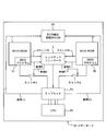
図1は、この発明のプログラム制御装置の一実施形態としてのBIOS起動装置を備えたマザーボード(全体を符号90で示す。)のブロック構成を示している。この実施形態では、選択されるべき制御プログラムは、BIOSであるものとする。
このマザーボード90は、第1の記憶部としてのBIOS-ROM1と、第2の記憶部としてのBIOS-ROM2と、第3の記憶部としてのBIOS設定記憶用ROM60と、エンベデッドコントローラ3と、このエンベデッドコントローラ3によってON(オン)、OFF(オフ)制御されるスイッチ4,5と、チップセット70と、CPU80とを搭載している。エンベデッドコントローラ3とスイッチ4,5とは、BIOS選択部を構成している。
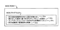
BIOS-ROM1,2は、いずれもフラッシュROMからなっている。BIOS-ROM1は、第1のBIOSのプログラム本体としてBIOSプログラム51を記憶している。BIOS-ROM2は、第2のBIOSのプログラム本体としてBIOSプログラム52を記憶している。例えばBIOSプログラム51は、図3に示すように、BIOS設定記憶用ROM60から設定(設定情報)を読み出す処理51aと、読み出した設定に基づきCPU80やチップセット70を設定する処理51bと、後述するエンベデッドコントローラ3のWDT(WatchDog Timer;ウォッチドッグタイマ)を一定周期でリセットする処理51cと、BIOS起動完了監視信号を制御する処理51dとを実行する。BIOSプログラム52は、BIOSプログラム51と同様の処理を実行する。これらの処理については、動作フローを用いて後に詳述する。
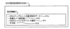
BIOS設定記憶用ROM60は、フラッシュROMからなり、図4Aに示すように、共通の設定情報61として、CPU80やチップセット70のための動作設定データ61aと、各種タイマ設定値61bと、OSが入っているデバイス(図示せず)の種別61cと、その他の情報61dとを記憶している。
この例では、CPU80やチップセット70のための設定情報は、BIOS設定記憶用ROM60のみに記憶されており、BIOS-ROM1,2には記憶されていない。
第1のBIOSは、BIOS-ROM1に記憶されているBIOSプログラム51と、BIOS設定記憶用ROM60に記憶されている設定情報とからなる。第2のBIOSは、BIOS-ROM2に記憶されているBIOSプログラム52と、BIOS設定記憶用ROM60に記憶されている設定情報とからなる。
図1中に示すように、スイッチ4はBIOS-ROM1とチップセット70との間に接続され、また、スイッチ5はBIOS-ROM2とチップセット70との間に接続されている。これらのスイッチ4,5は、ノーマリオフ(常開)スイッチであり、第1のBIOSと第2のBIOSとを切り替えて選択するためにエンベデッドコントローラ3によってON、OFF制御される。すなわち、第1のBIOSが選択されるときは、スイッチ4がONされ、スイッチ5がOFFに維持される。一方、第2のBIOSが選択されるときは、スイッチ4がOFFに維持され、スイッチ5がONされる。
エンベデッドコントローラ3は、図2に示すように、フラッシュROM31と、ハードウェア34とを含んでいる。
フラッシュROM31は、このエンベデッドコントローラ3が実行するプログラムを記憶しているプログラム記憶部32と、第1のBIOSと第2のBIOSとの間の起動優先度を記憶するBIOS優先度記憶部33とを有している。この起動優先度は、デフォルトでは、第1のBIOSが1位、第2のBIOSが2位になっているものとする。
ハードウェア34は、WDT35と、RAM(Random Access Memory;ランダム・アクセス・メモリ)36と、入出力ポート37とを含んでいる。WDT35は、時間を計数して、一定期間内に第1のBIOSまたは第2のBIOSの起動が完了したか否かを監視する。RAM36は、このエンベデッドコントローラ3の作業領域として用いられる。入出力ポート37は、WDT35をリセットするWDTリセット信号10,11を受けるためのポートと、スイッチ4,5をON、OFF制御するためのスイッチ制御信号6,7を出力するためのポートと、CPU80とチップセット70をリセットするためのリセット信号14を出力するためのポートと、第1,第2のBIOSが起動完了したことを表すBIOS監視信号8,9を受けるためのポートとを有している。
なお、BIOS監視信号8,9は、それぞれON、OFFを表す2値をとる。BIOS監視信号8,9がOFFであれば、BIOSが起動していないか、または起動が完了していないことを表す。BIOS監視信号8,9がONであれば、BIOSの起動が完了したことを表す。
図5は、エンベデッドコントローラ3の動作フローを示している。
図示しない電源がONされると、まずエンベデッドコントローラ3が起動する(ステップS1)。より正確には、フラッシュROM31のプログラム記憶部32に記憶されたプログラムが起動する。
続いて、エンベデッドコントローラ3は、1次選択部として働いて、BIOS優先度記憶部33に記憶されている起動優先度に応じてBIOSを選択する(ステップS2)。この例では、デフォルトで優先度が1位になっている第1のBIOSを選択する。具体的には、エンベデッドコントローラ3は、入出力ポート37を通してスイッチ制御信号6,7を出力して、スイッチ4をONし、スイッチ5をOFFに維持する。
続いて、エンベデッドコントローラ3は、入出力ポート37を通してリセット信号14を出力して、CPU80とチップセット70を初期状態にリセットする(ステップS3)。
続いて、エンベデッドコントローラ3は、後述するBIOSプログラム51からのWDTリセット信号10を受けて、WDT35のタイマを初期状態にリセットする。そして、WDT35のタイマが一定期間を計数(タイムアップ)するまで、BIOS(ここでは第1のBIOS)の起動が完了するのを待つ(ステップS4,S5)。
WDT35がタイムアップするまでに、後述するBIOSプログラム51からのBIOS監視信号8がONになったことを受けたとき、エンベデッドコントローラ3は、第1のBIOSの起動が完了したと判断する。第1のBIOSの起動が完了すれば(ステップS5でYES)、エンベデッドコントローラ3は、WDT35を停止して(ステップS12)、動作を完了する。
一方、WDT35がタイムアップするまでに第1のBIOSの起動が完了せず(ステップS5でNO)、WDT35がタイムアップしたとき(ステップS4でYES)、エンベデッドコントローラ3は、第1のBIOSが正常に起動しないと判断する。そして、エンベデッドコントローラ3は、2次選択部として働いて、第1のBIOSに代えて第2のBIOSを選択する。具体的には、スイッチ制御信号6によってスイッチ4をOFFし(ステップS6)、スイッチ制御信号7によってスイッチ5をONする(ステップS7)。
続いて、エンベデッドコントローラ3は、入出力ポート37を通してリセット信号14を出力して、CPU80とチップセット70を初期状態にリセットする(ステップS8)。
続いて、エンベデッドコントローラ3は、後述するBIOSプログラム52からのWDTリセット信号11を受けて、WDT35のタイマを初期状態にリセットする。そして、WDT35のタイマが一定期間を計数(タイムアップ)するまで、BIOS(ここでは第2のBIOS)の起動が完了するのを待つ(ステップS9,S10)。
WDT35がタイムアップするまでに、後述するBIOSプログラム52からのBIOS監視信号9がONになったことを受けたとき、エンベデッドコントローラ3は、第2のBIOSの起動が完了したと判断する。第2のBIOSの起動が完了すれば(ステップS10でYES)、エンベデッドコントローラ3は、起動優先度変更部として働いて、その起動したBIOS(ここでは第2のBIOS)について、BIOS優先度記憶部に記憶されている起動優先度を1位に変更する(ステップS11)。第1のBIOSの起動優先度は最下位に変更する。
その後、エンベデッドコントローラ3は、WDT35を停止して(ステップS12)、動作を完了する。
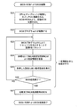
図6は、図5中のステップS4~S5において、第1のBIOS(つまり、BIOSプログラム51)を起動させる場合のBIOSプログラム51の動作フローを示している。
図5中のステップS3においてCPU80とチップセット70が初期状態にリセットされると、図6のステップS21に示すように、CPU80とチップセット70が起動して、スイッチ4に接続されたBIOS-ROM1から起動すべきBIOSを読み込む。これにより、ステップS22に示すように、BIOS-ROM1に記憶されているBIOSプログラム51が起動する。
そして、ステップS23に示すように、BIOSプログラム51は、エンベデッドコントローラ3へWDTリセット信号10を出力するとともに、BIOS監視信号8をOFF状態にする。既述のように、エンベデッドコントローラ3は、入出力ポート37を通してWDTリセット信号10を受けて、WDT35のタイマを初期状態にリセットする。
続いて、ステップS24に示すように、BIOSプログラム51は、チップセット70から参照信号12(図1参照)を送って、特定アドレスに割り当てられた、BIOS設定記憶用ROM60に記憶されている設定情報61を参照する。具体的には、例えば、CPU80やチップセット70のための動作設定データ61aと、各種タイマ設定値61bと、OSが入っているデバイス(図示せず)の種別61cを得る。
続いて、ステップS25に示すように、BIOSプログラム51は、取得した設定(設定情報61)に従って動作設定を実行する。そして、ステップS26に示すように、BIOSの起動が完了したか否かを判断する。
このようにしてBIOS(ここでは第1のBIOS)の起動が完了するまで、一定周期(例えば1秒周期)でステップS23~S26までの処理を繰り返す。
そして、第1のBIOSの起動が完了したとき(ステップS27でYES)、BIOSプログラム51はBIOS監視信号8をONにする。既述のように、エンベデッドコントローラ3は、WDT35がタイムアップするまでに、BIOS監視信号8がONになったか否かに応じて、第1のBIOSの起動が正常に完了したか否かを判断する。これにより、選択された第1のBIOSが起動するか否かを確実に判断できる。
図7は、図5中のステップS9~S10において、第2のBIOS(つまり、BIOSプログラム52)を起動させる場合のBIOSプログラム52の動作フローを示している。
図5中のステップS8においてCPU80とチップセット70が初期状態にリセットされると、図7のステップS31に示すように、CPU80とチップセット70が起動して、スイッチ5に接続されたBIOS-ROM2から起動すべきBIOSを読み込む。これにより、ステップS32に示すように、BIOS-ROM2に記憶されているBIOSプログラム52が起動する。
そして、ステップS33に示すように、BIOSプログラム52は、エンベデッドコントローラ3へWDTリセット信号11を出力するとともに、BIOS監視信号9をOFF状態にする。既述のように、エンベデッドコントローラ3は、入出力ポート37を通してWDTリセット信号11を受けて、WDT35のタイマを初期状態にリセットする。
続いて、ステップS34に示すように、BIOSプログラム52は、チップセット70から参照信号13(図1参照)を送って、特定アドレスに割り当てられた、BIOS設定記憶用ROM60に記憶されている設定情報61を参照する。具体的には、例えば、CPU80やチップセット70のための動作設定データ61aと、各種タイマ設定値61bと、OSが入っているデバイス(図示せず)の種別61cを得る。
続いて、ステップS35に示すように、BIOSプログラム52は、取得した設定(設定情報61)に従って動作設定を実行する。そして、ステップS36に示すように、BIOSの起動が完了したか否かを判断する。
このようにしてBIOS(ここでは第2のBIOS)の起動が完了するまで、一定周期(例えば1秒周期)でステップS33~S36までの処理を繰り返す。
そして、第2のBIOSの起動が完了したとき(ステップS37でYES)、BIOSプログラム52はBIOS監視信号9をONにする。既述のように、エンベデッドコントローラ3は、WDT35がタイムアップするまでに、BIOS監視信号9がONになったか否かに応じて、第2のBIOSの起動が正常に完了したか否かを判断する。これにより、選択された第2のBIOSが起動するか否かを確実に判断できる。
図5、図6および図7の動作フローから分かるように、エンベデッドコントローラ3は、まず1次選択部として働いて、BIOS優先度記憶部33に記憶されている起動優先度に応じて第1のBIOSを選択する。選択された第1のBIOSが起動しなかったとき、エンベデッドコントローラ3は、2次選択部として働いて、BIOS優先度記憶部33に記憶されている起動優先度に応じて第2のBIOSを選択する。このようにして、エンベデッドコントローラ3は、第1のBIOSと第2のBIOSとのいずれかを選択することができる。
ここで、第1のBIOSと第2のBIOSとのいずれが起動したとしても、BIOSプログラム51,52は、BIOS設定記憶用ROM60に記憶されている共通の設定情報61を参照して起動する。したがって、ユーザは、わざわざBIOSセットアップ画面を立ち上げて、起動したBIOSのための設定情報を設定する必要がない。つまり、第1のBIOSと第2のBIOSとのいずれが起動したとしても、ユーザが各種設定情報を設定する手間を省くことができる。
なお、BIOS優先度記憶部33に、デフォルトで第2のBIOSの起動優先度を1位、第2のBIOSの起動優先度を2位として記憶させておき、先に第2のBIOSの起動を試み、次に第1のBIOSの起動を試みても良い。
上述の例では、BIOSの数は、第1のBIOSと第2のBIOSとの2つとしたが、これに限られるものではない。BIOSの数は、3つ以上であっても良い。この場合、BIOS-ROM1,2に加えて、さらに第3のBIOSのプログラム本体を記憶したBIOS-ROM、第4のBIOSのプログラム本体を記憶したBIOS-ROM、…を設ける。そして、例えば図5中のステップS10で、WDT35がタイムアップするまでに第2のBIOSの起動が完了せず(ステップS10でNO)、WDT35がタイムアップしたとき(ステップS9でYES)、エンベデッドコントローラ3は、再び2次選択部として働いて、第2のBIOSに対する図5中のステップS6~S10と同様の処理を、第3のBIOS、第4のBIOS…に対して実行する(BIOSの数だけ繰り返す。)。これにより、複数のBIOSのうちいずれかのBIOSを起動させる。そして、いずれかのBIOSが起動したとき、その起動したBIOSについて、BIOS優先度記憶部33に記憶されている起動優先度を1位に変更する。
この結果、次回の起動時には、その起動したBIOSがまず選択される。その起動したBIOSは、次回の起動時にも正常に起動することが期待される。したがって、次回の起動時には、何回もBIOSの起動を試みることなく、迅速な起動を行うことができる。
また、上述の例では、第1および第2のBIOSのための共通の設定情報61がBIOS設定記憶用ROM60に記憶されているものとしたが、これに限られるものではない。第1および第2のBIOSのための共通の設定情報61は、プログラム本体としてのBIOSプログラム51,52が起動過程で参照できればどこに記憶されていても良く、例えばエンベデッドコントローラ3のフラッシュROM31に記憶されていても良い。
また、上述の例では、スイッチ4,5とともにエンベデッドコントローラ3がBIOS選択部として働いたが、これに限られるものではない。例えば、ハードウェア34、特にWDT35と入出力ポート37とを有するマイクロコンピュータであれば、BIOS選択部として働くためのエンベデッドコントローラ3の機能を実現することができる。
また、BIOS優先度記憶部33に記憶されている起動優先度とは別に、図4B中に示すように、BIOS設定記憶用ROM60にその他の情報61d′として、第1のBIOSと第2のBIOSとの間の起動優先度(BIOS優先度)を記憶しても良い。または、第1、第2のBIOSに加えて、第3のBIOS、第4のBIOS、…が選択可能な場合は、それらの多数のBIOSの間の起動優先度(BIOS優先度)を記憶しても良い。このようにした場合、フラッシュROM31のBIOS優先度記憶部33とBIOS設定記憶用ROM60とによって、BIOSの起動優先度を冗長化して記憶できる。したがって、フラッシュROM31(のBIOS優先度記憶部33)とBIOS設定記憶用ROM60のいずれかの記憶内容が破損していたとしても、複数のBIOSのうちのいずれかを選択することができる。
なお、BIOS優先度記憶部33に記憶されている起動優先度と、BIOS設定記憶用ROM60にその他の情報61d′として記憶されている起動優先度とは、例えばエンベデッドコントローラ3が定期的に同期させる(記憶内容を揃える)処理を行うのが望ましい。
上述の実施形態では、選択されるべき制御プログラムはBIOSであるものとしたが、これに限られるものではない。例えば、選択されるべき制御プログラムは、OS上で動作するアプリケーションプログラムであっても良い。その場合、この発明のプログラム制御装置によれば、複数のアプリケーションプログラムのうちいずれかのアプリケーションプログラムを選択して動作させることができる。その際、いずれのアプリケーションが起動したとしても、ユーザが設定情報を設定する手間を省くことができる。
当業者ならば分かるように、例えば一般的なタワー型のケーシングに、上記マザーボード90と、OSが入っているデバイスと、RAMなどを組み込めば、コンピュータを構成することができる。そのように構成されたコンピュータでは、複数の制御プログラムのうちいずれの制御プログラムが起動したとしても、ユーザが各種設定情報を設定する手間を省くことができる。さらに、この発明は、コンピュータに限られず、複数の制御プログラムのうちいずれかの制御プログラムを選択して動作させる情報処理装置に広く適用され得る。
1 第1のBIOS-ROM
2 第2のBIOS-ROM
3 エンベデッドコントローラ
60 BIOS設定記憶用ROM
90 マザーボード
2 第2のBIOS-ROM
3 エンベデッドコントローラ
60 BIOS設定記憶用ROM
90 マザーボード
Claims (8)
- 少なくとも第1の制御プログラムと第2の制御プログラムとを含む複数の制御プログラムのうちいずれかを選択して動作させるプログラム制御装置であって、
上記第1の制御プログラムのプログラム本体を記憶する第1の記憶部と、
上記第2の制御プログラムのプログラム本体を記憶する第2の記憶部と、
上記第1および第2の制御プログラムのための共通の設定情報を記憶する第3の記憶部と、
上記第1の制御プログラムと上記第2の制御プログラムとのいずれかを選択する制御プログラム選択部とを備え、
上記制御プログラム選択部によって選択された上記第1の制御プログラムまたは上記第2の制御プログラムのプログラム本体は、上記第3の記憶部に記憶されている共通の設定情報を参照することを特徴とするプログラム制御装置。 - 請求項1に記載のプログラム制御装置において、
上記第1の制御プログラムと上記第2の制御プログラムとの間の起動優先度を記憶する制御プログラム優先度記憶部を備え、
上記制御プログラム選択部は、
上記制御プログラム優先度記憶部に記憶されている起動優先度に応じて上記第1の制御プログラムと上記第2の制御プログラムとのいずれか一方を選択する1次選択部と、
上記1次選択部によって選択された制御プログラムが起動しなかったとき、別の制御プログラムを選択する2次選択部とを含むことを特徴とするプログラム制御装置。 - 請求項2に記載のプログラム制御装置において、
上記2次選択部によって選択された制御プログラムが起動したとき、その起動した制御プログラムについて、上記制御プログラム優先度記憶部に記憶されている起動優先度を1位に変更する起動優先度変更部を備えることを特徴とするプログラム制御装置。 - 請求項2または3に記載のプログラム制御装置において、
上記制御プログラム選択部は、
上記1次選択部または上記2次選択部によって制御プログラムが選択されたとき、その制御プログラムが選択されてからの時間を計数するタイマを備え、
上記タイマが計数する時間が一定時間に達しても上記選択された制御プログラムの起動が完了しないとき、上記選択された制御プログラムが起動しないと判断することを特徴とするプログラム制御装置。 - 請求項1から4までのいずれか一つに記載のプログラム制御装置において、
上記制御プログラム優先度記憶部に記憶されている起動優先度とは別に、上記第3の記憶部は上記第1の制御プログラムと上記第2の制御プログラムとの間の起動優先度を記憶していることを特徴とするプログラム制御装置。 - 少なくとも第1の制御プログラムと第2の制御プログラムとを含む複数の制御プログラムのうちいずれかを選択して動作させるプログラム制御装置であって、
上記第1の制御プログラムのプログラム本体を記憶する第1の記憶部と、
上記第2の制御プログラムのプログラム本体を記憶する第2の記憶部と、
上記第1の制御プログラムと上記第2の制御プログラムとの間の起動優先度を記憶する制御プログラム優先度記憶部と、
上記制御プログラム優先度記憶部に記憶されている起動優先度とは別に、上記第1の制御プログラムと上記第2の制御プログラムとの間の起動優先度を記憶する第3の記憶部と、
上記第1の制御プログラムと上記第2の制御プログラムとのいずれかを選択する制御プログラム選択部とを備え、
上記制御プログラム選択部は、
上記制御プログラム優先度記憶部または上記第3の記憶部に記憶されている起動優先度に応じて上記第1の制御プログラムと上記第2の制御プログラムとのいずれか一方を選択する1次選択部と、
上記1次選択部によって選択された制御プログラムが起動しなかったとき、別の制御プログラムを選択する2次選択部とを含むことを特徴とするプログラム制御装置。 - 請求項1から6までのいずれか一つに記載のプログラム制御装置を備えたことを特徴とするマザーボード。
- 請求項1から6までのいずれか一つに記載のプログラム制御装置を備えたことを特徴とする情報処理装置。
Applications Claiming Priority (2)
| Application Number | Priority Date | Filing Date | Title |
|---|---|---|---|
| JP2012-056978 | 2012-03-14 | ||
| JP2012056978A JP2015099408A (ja) | 2012-03-14 | 2012-03-14 | Bios起動装置およびマザーボード |
Publications (1)
| Publication Number | Publication Date |
|---|---|
| WO2013136997A1 true WO2013136997A1 (ja) | 2013-09-19 |
Family
ID=49160913
Family Applications (1)
| Application Number | Title | Priority Date | Filing Date |
|---|---|---|---|
| PCT/JP2013/055309 Ceased WO2013136997A1 (ja) | 2012-03-14 | 2013-02-28 | プログラム制御装置、マザーボードおよび情報処理装置 |
Country Status (3)
| Country | Link |
|---|---|
| JP (1) | JP2015099408A (ja) |
| TW (1) | TW201337762A (ja) |
| WO (1) | WO2013136997A1 (ja) |
Families Citing this family (2)
| Publication number | Priority date | Publication date | Assignee | Title |
|---|---|---|---|---|
| TWI722852B (zh) * | 2020-03-30 | 2021-03-21 | 技嘉科技股份有限公司 | 固態硬碟以及啟動方法 |
| US11789820B2 (en) * | 2021-02-19 | 2023-10-17 | Quanta Computer Inc. | Methods and systems for preventing hangup in a post routine from faulty bios settings |
Citations (4)
| Publication number | Priority date | Publication date | Assignee | Title |
|---|---|---|---|---|
| JP2002123401A (ja) * | 2000-08-01 | 2002-04-26 | Fujitsu Ltd | 処理装置、管理装置、記録媒体およびプログラム |
| JP2003316582A (ja) * | 2002-04-24 | 2003-11-07 | Nec System Technologies Ltd | 2重化biosの制御方法と装置 |
| JP2004295542A (ja) * | 2003-03-27 | 2004-10-21 | Sony Corp | 情報処理装置および方法、プログラム、並びに記録媒体 |
| JP2004355067A (ja) * | 2003-05-27 | 2004-12-16 | Konica Minolta Business Technologies Inc | 情報処理装置 |
-
2012
- 2012-03-14 JP JP2012056978A patent/JP2015099408A/ja active Pending
- 2012-11-13 TW TW101142126A patent/TW201337762A/zh unknown
-
2013
- 2013-02-28 WO PCT/JP2013/055309 patent/WO2013136997A1/ja not_active Ceased
Patent Citations (4)
| Publication number | Priority date | Publication date | Assignee | Title |
|---|---|---|---|---|
| JP2002123401A (ja) * | 2000-08-01 | 2002-04-26 | Fujitsu Ltd | 処理装置、管理装置、記録媒体およびプログラム |
| JP2003316582A (ja) * | 2002-04-24 | 2003-11-07 | Nec System Technologies Ltd | 2重化biosの制御方法と装置 |
| JP2004295542A (ja) * | 2003-03-27 | 2004-10-21 | Sony Corp | 情報処理装置および方法、プログラム、並びに記録媒体 |
| JP2004355067A (ja) * | 2003-05-27 | 2004-12-16 | Konica Minolta Business Technologies Inc | 情報処理装置 |
Also Published As
| Publication number | Publication date |
|---|---|
| JP2015099408A (ja) | 2015-05-28 |
| TW201337762A (zh) | 2013-09-16 |
Similar Documents
| Publication | Publication Date | Title |
|---|---|---|
| CN105027080B (zh) | 用于多重启动装置的启动顺序 | |
| US11954029B2 (en) | Configurable computer memory | |
| US7216223B2 (en) | Configuring multi-thread status | |
| JP5316432B2 (ja) | ネットワークコントローラの制御方法、プログラム及び情報処理装置 | |
| WO2012071852A1 (zh) | 引导程序的升级方法和装置 | |
| JP2013225208A (ja) | 情報処理装置、情報処理方法、及びプログラム | |
| WO2013136997A1 (ja) | プログラム制御装置、マザーボードおよび情報処理装置 | |
| CN104932914A (zh) | 多cpu启动电路和多cpu启动方法 | |
| JP5875558B2 (ja) | 情報処理装置 | |
| JP5960632B2 (ja) | 車両用電子制御装置 | |
| JP4522799B2 (ja) | 半導体回路装置及び暴走検出方法 | |
| JP4791792B2 (ja) | デジタルシグナルプロセッサシステムおよびそのブート方法。 | |
| CN110489169B (zh) | 一种片上系统的存储器快速启动方法 | |
| JP5071943B2 (ja) | 電子制御装置およびプログラム起動切替方法 | |
| TWI881625B (zh) | 用於處理電源開啟設定的方法及系統 | |
| CN102036025A (zh) | 一种soc芯片及其控制方法 | |
| JP6069185B2 (ja) | 電子機器及びアプリケーション初期化プログラム | |
| JP2009098769A (ja) | マルチプロセッサシステムおよび起動方法 | |
| JP5868535B2 (ja) | 画像形成装置 | |
| JP6072521B2 (ja) | コンピュータ起動システムおよびコンピュータ起動プログラムとコンピュータならびにコンピュータ起動方法 | |
| JP2011175503A (ja) | 数値制御装置の初期化方法及び数値制御装置 | |
| JP2012194819A (ja) | プログラム切替回路、および電子機器 | |
| JP2007058505A (ja) | 情報処理装置および情報処理装置起動方法 | |
| JP2013047883A (ja) | 情報処理装置及びその起動方法 | |
| JPH02183352A (ja) | コンピュータシステム |
Legal Events
| Date | Code | Title | Description |
|---|---|---|---|
| 121 | Ep: the epo has been informed by wipo that ep was designated in this application |
Ref document number: 13761392 Country of ref document: EP Kind code of ref document: A1 |
|
| NENP | Non-entry into the national phase |
Ref country code: DE |
|
| 122 | Ep: pct application non-entry in european phase |
Ref document number: 13761392 Country of ref document: EP Kind code of ref document: A1 |
|
| NENP | Non-entry into the national phase |
Ref country code: JP |