WO2013136405A1 - 回転電機 - Google Patents
回転電機 Download PDFInfo
- Publication number
- WO2013136405A1 WO2013136405A1 PCT/JP2012/056234 JP2012056234W WO2013136405A1 WO 2013136405 A1 WO2013136405 A1 WO 2013136405A1 JP 2012056234 W JP2012056234 W JP 2012056234W WO 2013136405 A1 WO2013136405 A1 WO 2013136405A1
- Authority
- WO
- WIPO (PCT)
- Prior art keywords
- rotor
- core
- refrigerant passage
- side refrigerant
- passage
- Prior art date
- Legal status (The legal status is an assumption and is not a legal conclusion. Google has not performed a legal analysis and makes no representation as to the accuracy of the status listed.)
- Ceased
Links
Images




Classifications
-
- H—ELECTRICITY
- H02—GENERATION; CONVERSION OR DISTRIBUTION OF ELECTRIC POWER
- H02K—DYNAMO-ELECTRIC MACHINES
- H02K9/00—Arrangements for cooling or ventilating
- H02K9/19—Arrangements for cooling or ventilating for machines with closed casing and closed-circuit cooling using a liquid cooling medium, e.g. oil
-
- H—ELECTRICITY
- H02—GENERATION; CONVERSION OR DISTRIBUTION OF ELECTRIC POWER
- H02K—DYNAMO-ELECTRIC MACHINES
- H02K1/00—Details of the magnetic circuit
- H02K1/06—Details of the magnetic circuit characterised by the shape, form or construction
- H02K1/22—Rotating parts of the magnetic circuit
- H02K1/32—Rotating parts of the magnetic circuit with channels or ducts for flow of cooling medium
-
- H—ELECTRICITY
- H02—GENERATION; CONVERSION OR DISTRIBUTION OF ELECTRIC POWER
- H02K—DYNAMO-ELECTRIC MACHINES
- H02K7/00—Arrangements for handling mechanical energy structurally associated with dynamo-electric machines, e.g. structural association with mechanical driving motors or auxiliary dynamo-electric machines
- H02K7/04—Balancing means
Definitions
- the present invention includes a rotatable rotor shaft including a shaft-side refrigerant passage provided therein, and a plurality of rotor-side refrigerant passages provided in the axial direction so as to communicate with the shaft-side refrigerant passage at a plurality of circumferential positions.
- the present invention relates to a rotating electrical machine including a rotor fixed to the outer diameter side of a rotor shaft and a stator.
- Conventionally known rotary electric machines such as motors for vehicles have a configuration including a rotor fixed to the outer diameter side of the rotor shaft and a stator disposed to face the outer diameter side of the rotor.
- the rotor may be composed of a rotor core and a plurality of permanent magnets embedded in the rotor core.
- the rotor is cooled in order to generate heat during use or the permanent magnet is demagnetized at a high temperature.
- the shaft side refrigerant passages are formed inside the rotor shaft, the rotor side refrigerant passages are formed in the axial direction at a plurality of locations in the circumferential direction inside the rotor, and the refrigerant is supplied to each rotor side refrigerant passage via the shaft side refrigerant passage.
- a so-called axial cooling structure in which the rotor is cooled by supplying a coolant (for example, cooling oil).
- Patent Document 1 the rotor unbalance that cools the rotor by axially cooling the coolant that has flowed from the inside of the rotor shaft to the inside of the end plate in the shaft center cooling structure.
- An automatic adjustment device is described.
- a rotor unbalance adjusting member is provided between the rotor core and the end plate. The rotor unbalance adjusting member rotates integrally with the rotor and decenters more greatly than the rotor with the eccentricity of the rotor.
- the adjusting member is located at the end of each lubricating oil passage and has a discharge hole for discharging the lubricating oil from each lubricating oil passage, and the liquid level of each lubricating oil passage at the time of rotor rotation is adjusted by the edge of each discharging hole. It is supposed to prescribe.
- Patent Document 2 includes a rotor yoke fixed to a rotating shaft of a rotating electrical machine, and a porous member fixed to the rotor yoke. An impregnated rotating body device is described. Thereby, it is said that balance adjustment can be automatically performed.
- Patent Document 3 is a liquid balancer that is mounted on a washing machine, and includes an outer peripheral side wall surface and an inner peripheral side wall surface that are formed around a rotation axis, contains liquid, and rotates around the rotation axis.
- a liquid balancer is described that includes an annular container that is arranged so as to be able to be provided and a buffer member that is fixed to the inner wall surface on the outer periphery side of the annular container.
- Patent Document 1 since the adjustment member is arrange
- the configuration described in Patent Document 2 and Patent Document 3 is not an axial center cooling structure, and in Patent Document 2, a porous member impregnated with a fluid is provided, and in Patent Document 3, an annular body that contains a fluid is provided. A container is provided. For this reason, the fluid used for resolving the rotational imbalance is not used for cooling the rotor, but the structure becomes complicated when used in the shaft center cooling structure, which may also increase the cost.
- An object of the present invention is to automatically eliminate a rotational unbalance of a rotor with a simple configuration in a rotating electrical machine having a shaft center cooling structure.
- the rotating electrical machine includes a rotatable rotor shaft including a shaft-side refrigerant passage provided therein, and a plurality of rotors provided in the axial direction so as to communicate with the shaft-side refrigerant passage at a plurality of circumferential positions.
- a rotary electric machine including an annular refrigerant passage provided in an annular shape centering on a rotation center axis of the rotor so as to communicate with a side refrigerant passage, and for circulating a coolant in a circumferential direction.
- the coolant used for cooling the rotor flows in the circumferential direction through the annular refrigerant passage and serves as a balance weight.
- the rotational unbalance of the rotor can be eliminated.
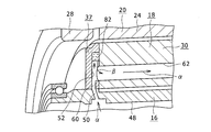
- FIG. 3 is a perspective view of only the rotor shaft and the rotor taken out from FIG. 2 and viewed from the right side to the left side in FIG. 2. It is the figure which looked at the rotor core of FIG. 2 to the axial direction which shows a mode that a cooling fluid is biased in the internal channel
- FIG. 4 is a cross-sectional view taken along line AA in FIG. 3.
- FIG. 3 is a partially enlarged perspective view showing a state in which a coolant flows inside the rotor of FIG. 2.
- FIG. 10 is a perspective view illustrating a state in which cooling liquid concentrates and accumulates on a part of the end plate of FIG. 9.
- FIG. 10 shows the 2nd example of another example of the end plate which comprises the rotary electric machine of embodiment which concerns on this invention.
- FIG. 6 is a view corresponding to FIG. 5 and showing a rotor of another example of the rotating electrical machine according to the embodiment of the present invention.
- the rotating electrical machine of the present embodiment flows coolant and cools the rotor and stator, and drives, for example, an electric vehicle, a fuel cell vehicle, and a hybrid vehicle equipped with an engine and a motor as a vehicle drive source.
- the present invention is applied to a rotating electric machine that is used as a motor for traveling, as a generator, or as a motor generator having both functions.
- a rotating electric machine that is used as a motor generator, both the first motor generator (MG1) mainly used as a generator and the second motor generator (MG2) mainly used as a traveling motor are used in the rotation of the present embodiment. Electric can be applied.
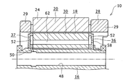
- FIG. 1 is a partial cross-sectional view showing a state in which the rotating electrical machine of the present embodiment is arranged in a case.
- the rotating electrical machine 10 includes a rotor shaft 16 rotatably supported by a bearing 14 on a casing 14 that is a motor case, a rotor 18 fixed to an outer diameter side of an intermediate portion of the rotor shaft 16, And a stator 20 disposed opposite to the outer diameter side of the rotor 18 with an air gap interposed therebetween.
- the stator 20 is fixed to the inner peripheral surface of the casing 14.
- Such a rotary electric machine employs a so-called shaft cooling structure, is a refrigerant, and cools the rotor 18 and the stator 20 with oil (cooling oil) such as ATF which is a coolant.
- oil cooling oil
- the stator 20 is configured by laminating a plurality of electromagnetic steel plates in the axial direction, and is formed so as to protrude in the radial direction at a plurality of locations in the circumferential direction on the inner circumferential surface of the stator core 24 and a stator core 24 formed of a magnetic material such as a laminate. Teeth 26 and a plurality of (for example, three-phase) stator coils 28 wound around the teeth 26. In the stator coil 28, a pair of coil ends 29 are formed by portions protruding outward from both axial side surfaces of the stator core 24.
- the stator core 24 is fixed to the inner surface of the casing 14.
- the multi-phase stator coil 28 is wound around the stator core 24 by concentrated winding or distributed winding.
- Casing 14 accommodates stator 20 and rotor 18.
- the rotor 18 includes a substantially cylindrical rotor core 30 formed of a magnetic material such as a laminate formed by laminating a plurality of electromagnetic steel plates in the axial direction, and the rotor core 30.
- permanent magnets 32 embedded at a plurality of locations in the inner circumferential direction.
- the permanent magnet 32 is adjacent to the circumferential direction (the “circumferential direction” refers to the circumferential direction of the rotor unless otherwise specified. The same applies throughout the present specification and claims).
- Two matching magnets are set as one set, and in each set, two permanent magnets 32 are arranged in a V shape so as to spread radially outward.
- each permanent magnet 32 is inserted into each magnet hole.
- Each permanent magnet 32 is in a direction inclined with respect to the radial direction (the “radial direction” means the radial direction of the rotor unless otherwise specified. The same applies throughout the present specification and claims). Magnetized. The magnetizing direction with respect to the radial direction of the permanent magnet 32 in each set is substantially the same.
- two substantially disc-shaped end plates 36 and 37 are arranged on both sides in the axial direction of the rotor core 30, and the rotor core 30 is sandwiched from both sides in the axial direction by the two end plates 36 and 37. Has been.
- an inner shaft member 38 is inserted inside the rotor shaft 16, an axial passage 40 through which cooling oil flows to the inner shaft member 38, and a radial passage 42 that communicates with the axial passage 40. And are formed.
- a substantially cylindrical intermediate passage 44 which is a shaft-side refrigerant passage, is formed between the outer peripheral surface of the intermediate portion of the inner shaft member 38 and the inner peripheral surface of the intermediate portion of the rotor shaft 16, and the intermediate passage 44 is a radial passage 42. It is connected to the radial direction passage 42 by being connected to the radially outer end.
- the rotor shaft 16 is formed with a through hole 48 penetrating in the axial direction at the center.
- the intermediate passage 44 is formed by the inner peripheral surface of the intermediate portion of the through hole 48 and the outer peripheral surface of the inner shaft member 38 in a state where the inner shaft member 38 is disposed inside the rotor shaft 16.
- an inclined hole 50 that is inclined with respect to the axial direction is formed at one or a plurality of locations in the circumferential direction of one end portion (left end portion in FIG. 2) of the rotor shaft 16.
- the inclined hole 50 communicates with the intermediate passage 44 (FIG. 1).
- the inclined hole 50 may be a radial hole provided along the radial direction of the rotor shaft 16.
- FIG. 7 is a perspective view showing only the right end plate in FIG.
- the right end plate 36 in FIG. 2 is formed to be recessed in an annular shape centering on the rotation center axis O in the radially intermediate portion of the inner surface facing the rotor core 30 (FIG. 2).
- An annular refrigerant passage 52 that is a plate-side refrigerant passage is included.
- the annular refrigerant passage 52 has a cylindrical outer peripheral inner wall surface 54 and a cylindrical inner peripheral inner wall surface 56 facing the outer peripheral inner wall surface 54.
- Each inner wall surface 54, 56 is formed in a cylindrical surface centered on the rotation center axis O.
- through holes 58 are formed through the axial direction so as to communicate with the outer surface at a plurality of locations in the circumferential direction at the bottom of the annular refrigerant passage 52.
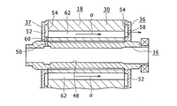
- the left end plate 37 in FIG. 2 has a shape in which a through-hole 58 is omitted in the right end plate 36 shown in FIG. That is, as shown in FIG. 5, the inner peripheral surface of the end plate 37 and the inside of the annular refrigerant passage 52 are communicated with one or a plurality of axially intermediate portions of the inner peripheral portion of the left end plate 37.
- a plate-side radial passage 60 is formed. The plate-side radial passage 60 communicates with an inclined hole 50 (or a radial hole) provided in the rotor shaft 16 at its inner peripheral side end (lower end in FIG. 5).
- the rotor core 30 has a plurality of core side refrigerant passages 62 which are provided at a plurality of locations in the circumferential direction and are respectively rotor side refrigerant passages penetrating in the axial direction. That is, the core-side refrigerant passage 62 penetrating in the axial direction is formed at a plurality of locations in the circumferential direction in the inner portion of the rotor core 30 with respect to the radial direction in the radial direction. Both axial openings of each core-side refrigerant passage 62 are opposed to the annular refrigerant passage 52 of the corresponding end plate 36 (or 37) in the axial direction.
- Each core-side refrigerant passage 62 is provided in the axial direction of the rotor core 30 so as to communicate with the intermediate passage 44 (FIG. 1) that is the shaft-side refrigerant passage and each annular refrigerant passage 52.
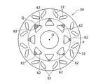
- the outer peripheral side inner wall surface 54 of each annular refrigerant passage 52 is provided on the outer side in the radial direction than the circumscribed circle (circle indicated by the broken line P in FIG. 4) of the plurality of core side refrigerant passages 62.
- Each annular refrigerant passage 52 is configured to allow cooling oil to flow in the circumferential direction.
- the inner shaft member 38 (FIG. 1) is pushed or sucked by a fluid supply source such as an oil pump (not shown).
- the cooling oil supplied to the intermediate passage 44 (FIG. 1) of the rotor shaft 16 through the radial passage 42) is supplied to the annular refrigerant passage 52 of the end plate 37 on one side through the inclined holes 50, and then a plurality of After flowing in the core-side refrigerant passage 62 in the axial direction, it is supplied to the annular refrigerant passage 52 of the other end plate 36 and ejected to the outside from each through hole 58.
- the rotor 18 including the permanent magnet 32 (FIG. 1) is cooled.
- the cooling oil jetted to the outside is shaken off radially outward by the centrifugal force when the rotor 18 rotates, collides with the coil end 22 of the stator 20, and the coil end 22 is also cooled.
- the fluid supply source is driven by a power source such as an engine.
- the rotation speed also changes.
- the cooling oil 82 flowing through the plurality of core-side refrigerant passages 62 provided in the rotor core 30 is reduced, and the inside of the core-side refrigerant passage 62 may not be completely filled.
- the amount of the cooling oil 82 inside the core-side refrigerant passages 62 varies.
- a large amount of cooling oil 82 is accumulated in a portion indicated by a symbol Q.
- the rotational unbalance based on the unbalance of the weight of the rotor 18 becomes large, which may cause vibration deterioration and noise deterioration.
- the annular refrigerant passages 52 communicating with the respective core side refrigerant passages 62 are provided in the end plates 36 and 37 as described above.
- the cooling oil 82 gradually accumulates from the outer peripheral side inside each annular refrigerant passage 52 by the action of centrifugal force when the rotor 18 rotates, and the cooling oil 82 is at least in the high-speed rotation region. This acts to eliminate the rotational imbalance of the rotor 18.
- the cooling oil 82 used for cooling the rotor 18 flows in the circumferential direction while changing the storage form of the annular refrigerant passage 52, and serves as a balance weight.
- the number of parts does not increase for eliminating the rotation imbalance, and the cost can be reduced.
- the rotational unbalance of the rotor 18 can be automatically eliminated with a simple configuration.
- the cooling oil 82 accumulated from the outer peripheral side of each annular refrigerant passage 52 reaches a portion facing each core-side refrigerant passage 62, it leaks into each core-side refrigerant passage 62 as shown by an arrow ⁇ in FIG. Since it flows out and flows into each core side refrigerant passage 62, the surplus oil can be used for rotor cooling for resolving rotation imbalance. For this reason, it becomes easy to appropriately regulate the maximum storage amount of the cooling oil 82 accumulated on the outer peripheral side of each annular refrigerant passage 52.
- each core-side refrigerant passage 62 provided in the rotor core 30 is illustrated as having a substantially triangular cross-sectional shape with only one apex provided radially outward.
- the shape of the core-side refrigerant passage 62 is not limited to this, and one having various shapes such as a circular shape, a rectangular shape, and a rhombus shape can be adopted.
- each core-side refrigerant passage 62 may have a substantially triangular cross-sectional shape in which only one vertex is provided on the radially inner side.
- the present embodiment may be applied to a configuration in which the end plate is provided only on one axial side of the rotor core. it can.
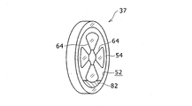
- FIG. 9 is a view showing a first example of another example of the end plate constituting the rotating electrical machine according to the embodiment of the present invention.
- FIG. 10 is a perspective view showing a state in which the cooling liquid concentrates and accumulates on a part of the end plate of FIG.
- the end plate 37 in FIGS. 9 and 10 corresponds to the left end plate 37 in FIG. 2 described above.
- the same or corresponding elements as those shown in FIGS. 1 to 8 are given the same reference numerals.
- the radial refrigerant passage 52 in the radial direction intermediate portion on the inner surface facing the rotor core 30, and the radial diameter communicating the annular refrigerant passage 52 and the inner peripheral surface of the end plate 37 are given the same reference numerals.
- a direction passage 64 is formed.
- Each radial passage 64 communicates with, for example, the inclined holes 50 or radial holes formed at a plurality of locations in the circumferential direction of the rotor shaft 16 of FIG. Even in such a configuration, as shown in FIG. 10, the cooling oil 82 is biased to a part of the circumferential direction in the annular refrigerant passage 52 during rotation according to the unbalance of the weight of the rotor 18 and automatically unrotated. Balance can be eliminated.
- Other configurations and operations are the same as those of the above-described embodiment shown in FIGS.
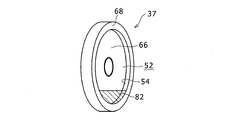
- FIG. 11 is a view corresponding to FIG. 10 and showing a second example of another example of the end plate constituting the rotating electrical machine of the embodiment according to the present invention.
- the end plate 37 in FIG. 11 also corresponds to the left end plate 37 in FIG.
- the end plate 37 of FIG. 11 is integrally provided with a cylindrical portion 68 on the outer peripheral portion of the inner surface in the axial direction of the disc portion 66 having an axial through hole formed in the center.
- An inner portion of the cylindrical portion 68 is an annular refrigerant passage 52.
- FIG. 12 is a view corresponding to FIG. 5 and showing a rotor of another example of the rotating electrical machine according to the embodiment of the present invention.
- the annular refrigerant passage 52 (see FIG. 2 and the like) is not formed in each end plate 70 in the above-described embodiments of FIGS. Instead, a plurality of plate-side refrigerant passages 72 are formed in portions of the end plates 70 facing the core-side refrigerant passages 62 at a plurality of positions in the circumferential direction, and penetrate through the bottom of each plate-side refrigerant passage 72 in the axial direction. A hole 74 is formed.
- an axial-side radial passage 76 penetrating in the radial direction is formed at one or a plurality of axially intermediate portions of the rotor shaft 16, and each core is disposed at a plurality of circumferential locations on the inner peripheral side portion of the rotor core 30.
- a core-side radial passage 78 that connects the side refrigerant passage 62 and the inner peripheral surface of the rotor core 30 is formed.
- the shaft-side radial passage 76 and each core-side radial passage 78 communicate with each other.
- each annular refrigerant passage 80 is formed in an annular shape so as to communicate with each core-side refrigerant passage 62 at two locations in the axial direction of the rotor core 30.
- the cooling oil supplied between the outer peripheral surface of the inner shaft member 38 (see FIG. 1) and the inner peripheral surface of the rotor shaft 16 is in the direction indicated by the arrow ⁇ in FIG.
- the flow passes through the direction passage 76, the core side radial passage 78, and the core side refrigerant passage 62 in this order, and is ejected to the outside through the plate side refrigerant passage 72 and the through hole 74 from both axial sides of each core side refrigerant passage 62.
- the cooling oil is also supplied to the annular refrigerant passages 80 provided in the rotor core 30 by the action of centrifugal force when the rotor 18 rotates, and flows in the circumferential direction.
- annular refrigerant passage 52 provided in the rotor core 30 only needs to be provided in at least a part of the rotor core 30 in the axial direction. For example, only one may be provided in the central portion in the axial direction.
- the inner shaft member 38 is disposed on the inner side of the rotor shaft 16, but the inner shaft member 38 is omitted and the shaft-side refrigerant passage formed by the through hole 48 of the rotor shaft 16.
- the cooling oil can be supplied to the rotor 18 to cool the rotor 18.
- the rotor core 30 can be constituted by a powder magnetic core formed by press-molding magnetic powder in addition to a laminated body formed by laminating a plurality of steel plates.
- cooling water or the like can be used as the cooling liquid.
- the permanent magnet 32 is not limited to the configuration in which the permanent magnet 32 is disposed in a V shape on the rotor core 30.
- the permanent magnets can be disposed at a plurality of locations on concentric circles centering on the central axis of the rotor core 30.
- the rotor is not limited to a configuration having permanent magnets, and the present invention can also be applied to a configuration in which rotor coils are provided at a plurality of locations in the circumferential direction.
Landscapes
- Engineering & Computer Science (AREA)
- Power Engineering (AREA)
- Motor Or Generator Cooling System (AREA)
- Iron Core Of Rotating Electric Machines (AREA)
Abstract
回転電機は、内部に設けられた軸側冷媒通路である中間通路を含み回転可能なロータシャフト16と、周方向複数個所に中間通路と連通するように軸方向に設けられた複数のロータ側冷媒通路であるコア側冷媒通路62を有し、ロータシャフト16の外径側に固定されるロータ18と、ロータ18の外径側に対向配置されるステータとを含む。ロータ18は、軸方向の少なくとも一部にロータ側冷媒通路である各コア側冷媒通路62と連通するように、ロータ18の回転中心軸を中心とする円環状に設けられ、内部に冷却液を周方向に流通させる環状冷媒通路52を含む。
Description
本発明は、内部に設けられた軸側冷媒通路を含み回転可能なロータシャフトと、周方向複数個所に軸側冷媒通路と連通するように軸方向に設けられた複数のロータ側冷媒通路を含み、ロータシャフトの外径側に固定されるロータと、ステータとを含む回転電機に関する。
従来から知られている、車両用電動機等の回転電機として、ロータシャフトの外径側に固定されたロータと、ロータの外径側に対向配置されたステータとを備える構成がある。また、ロータは、ロータコアと、ロータコアの内部に埋め込まれた複数の永久磁石とにより構成する場合がある。このような回転電機では、使用時にロータが発熱したり、永久磁石が高温で減磁する等のためにロータを冷却することが行われている。例えば、ロータシャフトの内部に軸側冷媒通路を形成するとともに、ロータの内部の周方向複数個所に軸方向にロータ側冷媒通路を形成し、軸側冷媒通路を介して各ロータ側冷媒通路に冷媒である冷却液(例えば冷却油)を供給することにより、ロータを冷却する、いわゆる軸心冷却構造とすることが考えられる。
また、特許文献1では、軸心冷却構造でロータシャフトの内部からエンドプレートの内側を流れた冷却液がロータの内部に設けられた潤滑油通路を軸方向に流れてロータを冷却するロータアンバランス自動調整装置が記載されている。この装置では、ロータコアとエンドプレートとの間に、ロータと一体に回転し、ロータの偏心に伴ってロータよりも大きく偏心するロータアンバランス調整部材が設けられている。調整部材は、各潤滑油通路の端部に位置して各潤滑油通路から潤滑油を排出する排出孔を有し、各排出孔の縁部によってロータ回転時の各潤滑油通路の液面を規定するとされている。
一方、特許文献2には、回転電機の回転軸に固定された回転子ヨークと、回転子ヨークに固定された多孔質部材とを有し、多孔質部材は、円環状に形成され、流体が含浸された回転体装置が記載されている。これにより自動的にバランス調整を行うことができるとされている。
また、特許文献3には、洗濯機に装着される液体バランサであって、回転軸線の周りに形成された外周側壁面及び内周側壁面を含み、液体を収容して回転軸線を中心に回転できるように配置された環状容器と、環状容器の外周側内壁面に固着された緩衝部材とを備える液体バランサが記載されている。
上記のようにロータの周方向複数個所に複数のロータ側冷媒通路が形成された軸心冷却構造で軸側冷媒通路を介して各ロータ側冷媒通路に冷却液を流す構成では、オイルポンプ等の冷却液供給源の吐出流量が場合により変化して吐出流量が少なくなる等の場合に、各ロータ側冷媒通路同士で内部を流れる冷却液が変化するという、冷却液の供給ばらつきが生じる可能性がある。この場合、各ロータ側冷媒通路の内部同士で冷却液の量に偏りが発生する。このため、ロータの重心の回転軸に対する芯ズレが生じて、ロータの回転バランスが悪化し、主に回転1次の振動や騒音が発生し、NV性能が悪化する可能性がある。このため、回転電機において、ロータの回転アンバランスを自動的に解消できる構成の実現が望まれている。
これに対して、特許文献1ではエンドプレートの内側に調整部材を配置し、調整部材の複数個所を潤滑油通路に挿入しているため、特殊な形状を有する調整部材を必要とし、コストが上昇する可能性がある。また、特許文献2及び特許文献3に記載された構成は軸心冷却構造ではなく、しかも特許文献2では流体が含浸された多孔質部材が設けられ、特許文献3では内部に流体を収容する環状容器が設けられている。このため、回転アンバランスの解消に用いられる流体はロータの冷却のために用いられるものではなく、軸心冷却構造に使用する場合に構造が複雑になり、やはりコストが上昇する可能性がある。
本発明の目的は、軸心冷却構造の回転電機において、簡易な構成で自動的にロータの回転アンバランスを解消することである。
本発明に係る回転電機は、内部に設けられた軸側冷媒通路を含み回転可能なロータシャフトと、周方向複数個所に前記軸側冷媒通路と連通するように軸方向に設けられた複数のロータ側冷媒通路を含み、前記ロータシャフトの外径側に固定されるロータと、前記ロータの外径側に対向配置されるステータとを備え、前記ロータは、軸方向の少なくとも一部に前記各ロータ側冷媒通路と連通するように、前記ロータの回転中心軸を中心とする円環状に設けられ、内部に冷却液を周方向に流通させる環状冷媒通路を含むことを特徴とする回転電機である。
本発明に係る回転電機によれば、軸心冷却構造の構成において、ロータの冷却のために用いる冷却液が環状冷媒通路を周方向に流れてバランスウェイトの役目を果たすので、簡易な構成で自動的にロータの回転アンバランスを解消できる。
以下において、図1~8を用いて本発明に係る実施形態を説明する。本実施形態の回転電機は、冷却液を流し、ロータ及びステータを冷却するものであって、例えば電気自動車や、燃料電池車や、エンジン及びモータを車両の駆動源として搭載するハイブリッド車両を駆動する走行用のモータとして、または、発電機として、または、その両方の機能を有するモータジェネレータとして使用する回転電機に適用する。例えば、回転電機をモータジェネレータとして使用する場合、主として発電機として使用する第1モータジェネレータ(MG1)でも、主として走行用モータとして使用する第2モータジェネレータ(MG2)でも、いずれでも本実施形態の回転電機を適用できる。
図1は、本実施形態の回転電機をケース内に配置した様子を示す部分断面図である。図1に示すように、回転電機10は、モータケースであるケーシング14に軸受により回転可能に支持されたロータシャフト16と、ロータシャフト16の中間部の外径側に固定されたロータ18と、ロータ18の外径側にエアギャップを介して対向配置されたステータ20とを備える。ステータ20は、ケーシング14の内周面に固定されている。このような回転電機は、いわゆる軸心冷却構造を採用し、冷媒であり、冷却液であるATF等の油(冷却油)により、ロータ18とステータ20とを冷却している。
ステータ20は、複数の電磁鋼板を軸方向に積層することにより構成され、積層体等の磁性材により形成されるステータコア24と、ステータコア24の内周面の周方向複数個所に径方向に突出形成されたティース26と、ティース26に巻装された複数相(例えば3相の)のステータコイル28とを含む。ステータコイル28において、ステータコア24の軸方向両側面よりも外側に突出する部分により、一対のコイルエンド29が形成されている。ステータコア24は、ケーシング14の内面に固定されている。複数相のステータコイル28は、集中巻きまたは分布巻きでステータコア24に巻装されている。
ケーシング14は、ステータ20とロータ18とを収容している。図2~図6に示すように、ロータ18は、複数の電磁鋼板を軸方向に積層することにより構成される積層体等の磁性材により形成される略円筒状のロータコア30と、ロータコア30の内部の周方向複数個所に埋め込まれた永久磁石32とを含む。図4に示すように、永久磁石32は、周方向(「周方向」とは特に断らない限り、ロータの周方向をいう。本明細書全体及び特許請求の範囲で同じとする。)に隣り合う2つを1組として、各組で、2つの永久磁石32がV字形に径方向外側に広がるように配置されている。すなわち、ロータコア30の内部の外周寄り部分に軸方向に貫通する複数の磁石孔が形成されており、各永久磁石32は各磁石孔に挿入されている。また、各永久磁石32は、径方向(「径方向」とは特に断らない限り、ロータの径方向をいう。本明細書全体及び特許請求の範囲で同じとする。)に対し傾斜する方向に着磁されている。各組で永久磁石32の径方向に関する着磁方向は略同じとしている。
また、図5に示すように、ロータコア30の軸方向両側に2つの略円板状のエンドプレート36,37が配置されており、2つのエンドプレート36,37によりロータコア30が軸方向両側から挟持されている。
また、図1に示すように、ロータシャフト16の内側に内側軸部材38が挿入されており、内側軸部材38に冷却油を流す軸方向通路40と、軸方向通路40に通じる径方向通路42とが形成されている。内側軸部材38の中間部外周面とロータシャフト16の中間部内周面との間に軸側冷媒通路である略円筒状の中間通路44が形成されており、中間通路44は、径方向通路42の径方向外端に接続されることで、径方向通路42に連通している。
図2に示すように、ロータシャフト16は、中心部に軸方向に貫通する貫通孔48が形成されている。図1に示すようにロータシャフト16の内側に内側軸部材38が配置された状態で、貫通孔48の中間部内周面と内側軸部材38の外周面とにより上記の中間通路44が形成される。また、ロータシャフト16の一端部(図2の左端部)の周方向1個所または複数個所に、軸方向に対し傾斜した傾斜孔50が形成されている。傾斜孔50は、中間通路44(図1)と連通している。なお、傾斜孔50は、ロータシャフト16の径方向に沿って設けた径方向孔とすることもできる。
図7は、図2の右側のエンドプレートのみを取り出して示す斜視図である。図7に示すように、図2の右側のエンドプレート36は、ロータコア30(図2)と対向する内側面の径方向中間部に回転中心軸Oを中心とする円環状に窪んで形成されたプレート側冷媒通路である環状冷媒通路52を含む。環状冷媒通路52は、円筒面状の外周側内壁面54と外周側内壁面54に対向する円筒面状の内周側内壁面56とを有する。各内壁面54,56は、回転中心軸Oを中心とする円筒面状に形成されている。また、図3、図7に示すように、環状冷媒通路52の底部の周方向複数個所に外側面に通じるように軸方向に貫通させた貫通孔58が形成されている。
なお、図2の左側のエンドプレート37は、図7に示した右側のエンドプレート36において、貫通孔58を省略するが、後述するプレート側径方向通路60が形成された形状を有する。すなわち、図5に示すように、左側のエンドプレート37の内周寄り部分の軸方向中間部の1個所または複数個所に、エンドプレート37の内周面と環状冷媒通路52の内部とを連通させるプレート側径方向通路60が形成されている。プレート側径方向通路60は、その内周側端部(図5の下端部)でロータシャフト16に設けられた傾斜孔50(または径方向孔)と連通している。
また、ロータコア30は、周方向複数個所に設けられ、それぞれ軸方向に貫通するロータ側冷媒通路である複数のコア側冷媒通路62を有する。すなわち、ロータコア30の内部で径方向に関して永久磁石32よりも内側部分の周方向複数個所に軸方向に貫通するコア側冷媒通路62が形成されている。各コア側冷媒通路62の軸方向両端開口はそれぞれ対応する側のエンドプレート36(または37)の環状冷媒通路52と軸方向に対向している。各コア側冷媒通路62は、軸側冷媒通路である中間通路44(図1)及び各環状冷媒通路52と連通するようにロータコア30の軸方向に設けられている。各環状冷媒通路52の外周側内壁面54は、複数のコア側冷媒通路62の外接円(図4の破線Pで示す円)よりも径方向に関して外側に設けられている。また、各環状冷媒通路52は、内部に冷却油を周方向に流通させるように構成されている。
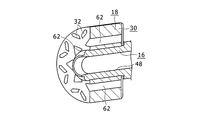
このように構成されるので、図1、図5、図8で矢印αで示すように、図示しないオイルポンプ等の流体供給源により押し出されるまたは吸引される等により、内側軸部材38(図1)の径方向通路42を通じてロータシャフト16の中間通路44(図1)に供給された冷却油は、傾斜孔50を介して片側のエンドプレート37の環状冷媒通路52に供給され、その後、複数のコア側冷媒通路62に軸方向に流れた後、他側のエンドプレート36の環状冷媒通路52に供給されて、各貫通孔58から外側に噴出される。これにより、永久磁石32(図1)を含むロータ18が冷却される。外側に噴出された冷却油は、ロータ18回転時の遠心力により径方向外側に振り飛ばされてステータ20のコイルエンド22に衝突し、コイルエンド22も冷却される。
一方、流体供給源は、エンジン等の動力源により駆動され、回転電機10を搭載する車両の速度変化や要求冷却量の変化等に基づくこの動力源の回転速度の変化に応じて流体供給源の回転速度も変化する。このため、図4に示すように、ロータコア30に設けられた複数のコア側冷媒通路62に流れる冷却油82が少なくなり、コア側冷媒通路62の内部を完全には満たすことがない場合が生じる可能性がある。また、この場合に、複数のコア側冷媒通路62同士で内部の冷却油82の量にばらつきが生じる可能性もある。例えば、図4では、符号Qを付した部分に集中して多くの冷却油82が溜まっている。このため、何らの工夫をしない場合には、ロータ18の重量のアンバランスに基づく回転アンバランスが大きくなり、振動悪化や騒音悪化の要因となる可能性がある。
これに対して、本実施形態では、上記のように各コア側冷媒通路62と連通する環状冷媒通路52が各エンドプレート36,37に設けられている。このため、図8に示すように、ロータ18の回転時に遠心力の作用で各環状冷媒通路52の内部に外周側から徐々に冷却油82が溜まり、さらにこの冷却油82が少なくとも高速回転領域でロータ18の回転アンバランスを解消するように作用する。すなわち、各コア側冷媒通路62同士で内部に溜まる冷却油82の量にばらつきが生じてロータ18の重心が回転中心からずれる場合、高速回転ではその重心のずれた側と反対側に各環状冷媒通路52内で冷却油82が分離または集中して溜まる傾向となる。このため、少なくとも高速回転領域でロータ18の回転アンバランスが修正され、振動及び騒音を抑制することができる。すなわち、ロータ18の冷却のために用いる冷却油82が環状冷媒通路52を貯留形態を変える等しながら周方向に流れてバランスウェイトの役目を果たす。また、回転アンバランスの解消のために部品点数が多くなることがなく、コストを低減できる。この結果、軸心冷却構造の構成において、簡易な構成で自動的にロータ18の回転アンバランスを解消できる。また、各環状冷媒通路52の外周側から溜まった冷却油82が各コア側冷媒通路62と対向する部分にまで達すると、図8に矢印βで示すように、各コア側冷媒通路62に漏れ出て各コア側冷媒通路62に流れるので、回転アンバランスの解消用としては余った油をロータ冷却用として使用できる。このため、各環状冷媒通路52の外周側に溜まる冷却油82の最大貯留量を適切に規制しやすくなる。
なお、上記の実施形態では、ロータコア30に設けられた各コア側冷媒通路62が径方向外側に頂点が1つのみ設けられた略三角形の断面形状を有するような図示をしているが、各コア側冷媒通路62の形状はこれに限定するものではなく、断面が円形、矩形、ひし形等、種々の形状を有するものを採用できる。例えば、各コア側冷媒通路62は、径方向内側に頂点が1つのみ設けられた略三角形の断面形状を有するものも採用できる。また、上記ではロータコア30の両側に2つのエンドプレート36,37が設けられた場合を説明したが、本実施形態は、ロータコアの軸方向片側のみにエンドプレートが設けられた構成に適用することもできる。
図9は、本発明に係る実施形態の回転電機を構成するエンドプレートの別例の第1例を示す図である。図10は、図9のエンドプレートの一部に冷却液が集中して溜まる様子を示す斜視図である。図9、図10のエンドプレート37は、上記の図2の左側のエンドプレート37に対応する。なお、以下の説明では、上記の図1~8に示した要素と同一または対応する要素には同一の符号を付して説明する。図9、図10に示すエンドプレート37では、ロータコア30と対向する内側面に径方向中間部の環状冷媒通路52と、環状冷媒通路52とエンドプレート37の内周面とを連通させる放射状の径方向通路64とが形成されている。各径方向通路64は、例えば図5のロータシャフト16の周方向複数個所に形成された傾斜孔50または径方向孔と連通させる。このような構成でも、図10に示すように、ロータ18の重量のアンバランスに応じて回転時に環状冷媒通路52内で周方向の一部等に冷却油82を偏らせて自動的に回転アンバランスを解消することができる。その他の構成及び作用は、上記の図1~8の実施形態と同様である。
図11は、本発明に係る実施形態の回転電機を構成するエンドプレートの別例の第2例を示す、図10に対応する図である。図11のエンドプレート37も、上記の図2の左側のエンドプレート37に対応する。図11のエンドプレート37は、中心部に軸方向の貫通孔が形成された円板部66の軸方向内側面の外周部に円筒部68が一体に設けられている。この円筒部68の内側部分が環状冷媒通路52となっている。このようなエンドプレート37はロータシャフト16の外側に嵌合固定した状態で、ロータシャフト16の傾斜孔50または径方向孔と環状冷媒通路52とを連通させる。その他の構成及び作用は、上記の図1~8の実施形態または図9の構成と同様である。
図12は、本発明に係る実施形態の回転電機の別例のロータを示す、図5に対応する図である。図12のロータ18では、上記の図1~8の実施形態において、各エンドプレート70に環状冷媒通路52(図2等参照)が形成されていない。その代わりに各エンドプレート70の周方向複数個所で各コア側冷媒通路62と対向する部分に複数のプレート側冷媒通路72が形成され、各プレート側冷媒通路72の底部に軸方向に貫通する貫通孔74が形成されている。また、ロータシャフト16の軸方向中間部の1個所または複数個所に径方向に貫通する軸側径方向通路76が形成されるとともに、ロータコア30の内周側部分の周方向複数個所に、各コア側冷媒通路62とロータコア30の内周面とを連通させるコア側径方向通路78が形成されている。そして軸側径方向通路76と各コア側径方向通路78とが連通している。
また、ロータコア30の軸方向両端寄りの2個所位置に、各コア側冷媒通路62の径方向外端部に連通するようにロータ18の回転中心Oを中心とする円環状に形成された環状冷媒通路80が設けられている。すなわち、各環状冷媒通路80は、ロータコア30の軸方向の2個所に、各コア側冷媒通路62と連通するように円環状に形成されている。
このような構成では、内側軸部材38(図1参照)の外周面とロータシャフト16の内周面との間に供給された冷却油が、図12の矢印γで示す方向に、軸側径方向通路76、コア側径方向通路78、コア側冷媒通路62に順に流れて、各コア側冷媒通路62の軸方向両側から各プレート側冷媒通路72及び貫通孔74を通じて外側に噴出される。この場合、ロータコア30に設けられた各環状冷媒通路80にもロータ18回転時の遠心力の作用により冷却油が供給され、内部を周方向に流れる。このため、各コア側冷媒通路62同士の間で内部の冷却油のばらつきが生じる場合でも、各環状冷媒通路80内の冷却油が各環状冷媒通路80を周方向に流れてバランスウェイトの役目を果たすので、簡易な構成で自動的にロータ18の回転アンバランスを解消できる。その他の構成及び作用は、上記の図1~図8の実施形態と同様である。なお、ロータコア30に設けられた環状冷媒通路52は、ロータコア30の少なくとも軸方向の一部に設けられていればよく、例えば軸方向中央部に1つのみを設けることもできる。
なお、上記の各実施形態では、ロータシャフト16の内側に内側軸部材38を配置しているが、内側軸部材38を省略して、ロータシャフト16の貫通孔48により形成される軸側冷媒通路に冷却油を供給し、ロータ18を冷却することもできる。
また、ロータコア30は、複数の鋼板を積層してなる積層体により構成する以外に、磁性粉末を加圧成形してなる圧粉磁心により構成することもできる。また、冷却液として、油以外、例えば冷却水等を用いることもできる。また、永久磁石32はロータコア30にV字形に配置する構成に限定するものではなく、例えば、ロータコア30の中心軸を中心とする同心円上の複数個所に永久磁石を配置することもできる。また、ロータは、永久磁石を有する構成に限定せず、周方向複数個所にロータコイルが設けられた構成に本発明を適用することもできる。
10 回転電機、14 ケーシング、16 ロータシャフト、18 ロータ、20 ステータ、22 コイルエンド、24 ステータコア、26 ティース、28 ステータコイル、29 コイルエンド、30 ロータコア、32 永久磁石、36,37 エンドプレート、38 内側軸部材、40 軸方向通路、42 径方向通路、44 中間通路、48 貫通孔、50 傾斜孔、52 環状冷媒通路、54 外周側内壁面、56 内周側内壁面、58 貫通孔、60 プレート側径方向通路、62 コア側冷媒通路、64 径方向通路、66 円板部、68 円筒部、70 エンドプレート、72 プレート側冷媒通路、74 貫通孔、76 軸側径方向通路、78 コア側径方向通路、80 環状冷媒通路、82 冷却油。
Claims (4)
- 内部に設けられた軸側冷媒通路を含み回転可能なロータシャフトと、
周方向複数個所に前記軸側冷媒通路と連通するように軸方向に設けられた複数のロータ側冷媒通路を含み、前記ロータシャフトの外径側に固定されるロータと、
前記ロータの外径側に対向配置されるステータとを備え、
前記ロータは、
軸方向の少なくとも一部に前記各ロータ側冷媒通路と連通するように、前記ロータの回転中心軸を中心とする円環状に設けられ、内部に冷却液を周方向に流通させる環状冷媒通路を含むことを特徴とする回転電機。 - 請求項1に記載の回転電機において、
前記ロータは、
周方向複数個所に設けられ、それぞれ軸方向に貫通する前記ロータ側冷媒通路である複数のコア側冷媒通路を有するロータコアと、
前記ロータコアの軸方向両側のうち、少なくとも軸方向片側に設けられたエンドプレートとを含み、
前記環状冷媒通路は、前記エンドプレートに前記各コア側冷媒通路と連通するように円環状に形成されていることを特徴とする回転電機。 - 請求項1に記載の回転電機において、
前記ロータは、
周方向複数個所に設けられ、それぞれ軸方向に貫通する前記ロータ側冷媒通路である複数のコア側冷媒通路を有するロータコアを含み、
前記環状冷媒通路は、前記ロータコアの少なくとも軸方向の一部に前記各コア側冷媒通路と連通するように円環状に形成されていることを特徴とする回転電機。 - 請求項1から請求項3のいずれか1に記載の回転電機において、
前記環状冷媒通路は、前記複数のロータ側冷媒通路の外接円よりも径方向に関して外側に設けられる円環状の外周側内壁面を有することを特徴とする回転電機。
Priority Applications (1)
| Application Number | Priority Date | Filing Date | Title |
|---|---|---|---|
| PCT/JP2012/056234 WO2013136405A1 (ja) | 2012-03-12 | 2012-03-12 | 回転電機 |
Applications Claiming Priority (1)
| Application Number | Priority Date | Filing Date | Title |
|---|---|---|---|
| PCT/JP2012/056234 WO2013136405A1 (ja) | 2012-03-12 | 2012-03-12 | 回転電機 |
Publications (1)
| Publication Number | Publication Date |
|---|---|
| WO2013136405A1 true WO2013136405A1 (ja) | 2013-09-19 |
Family
ID=49160379
Family Applications (1)
| Application Number | Title | Priority Date | Filing Date |
|---|---|---|---|
| PCT/JP2012/056234 Ceased WO2013136405A1 (ja) | 2012-03-12 | 2012-03-12 | 回転電機 |
Country Status (1)
| Country | Link |
|---|---|
| WO (1) | WO2013136405A1 (ja) |
Cited By (13)
| Publication number | Priority date | Publication date | Assignee | Title |
|---|---|---|---|---|
| WO2015087445A1 (ja) * | 2013-12-13 | 2015-06-18 | 三菱電機株式会社 | 永久磁石埋込型回転電機 |
| WO2017214234A1 (en) * | 2016-06-07 | 2017-12-14 | Tesla, Inc. | Electric motor waste heat mode to heat battery |
| US10819172B2 (en) * | 2017-08-25 | 2020-10-27 | Honda Motor Co., Ltd. | Rotor for rotating electric machine, magnetic steel sheet for rotating electric machine, and electric vehicle |
| US10967702B2 (en) | 2017-09-07 | 2021-04-06 | Tesla, Inc. | Optimal source electric vehicle heat pump with extreme temperature heating capability and efficient thermal preconditioning |
| CN112787444A (zh) * | 2019-11-01 | 2021-05-11 | 通用汽车环球科技运作有限责任公司 | 具有基于强制对流的转子冷却的电机 |
| US11081921B2 (en) * | 2017-03-28 | 2021-08-03 | Honda Motor Co., Ltd. | Rotor |
| CN114142642A (zh) * | 2021-12-06 | 2022-03-04 | 臻驱科技(上海)有限公司 | 一种驱动电机的油冷结构 |
| EP3920384A4 (en) * | 2020-01-15 | 2022-04-27 | Huawei Digital Power Technologies Co., Ltd. | ENGINE ROTOR AND VEHICLE |
| WO2022233114A1 (zh) * | 2021-05-07 | 2022-11-10 | 中国第一汽车股份有限公司 | 一种应用于高速永磁电机转子与绕组的直接冷却系统 |
| US11932078B2 (en) | 2021-03-31 | 2024-03-19 | Tesla, Inc. | Electric vehicle heat pump using enhanced valve unit |
| WO2024160344A1 (en) * | 2023-01-30 | 2024-08-08 | Gkn Automotive Limited | Electric machine with oil cooling |
| EP4525274A1 (de) * | 2023-09-18 | 2025-03-19 | Robert Bosch GmbH | Rotor einer elektrischen maschine |
| WO2026077595A1 (de) * | 2024-10-11 | 2026-04-16 | Mahle International Gmbh | Stirnseitige scheibe mit einem ringkanal für einen rotor einer elektrischen maschine, insbesondere eines extern erregten synchronmotors |
Citations (2)
| Publication number | Priority date | Publication date | Assignee | Title |
|---|---|---|---|---|
| JP2009055737A (ja) * | 2007-08-28 | 2009-03-12 | Toyota Motor Corp | ロータおよび回転電機 |
| JP2010220340A (ja) * | 2009-03-16 | 2010-09-30 | Toyota Motor Corp | 回転電機 |
-
2012
- 2012-03-12 WO PCT/JP2012/056234 patent/WO2013136405A1/ja not_active Ceased
Patent Citations (2)
| Publication number | Priority date | Publication date | Assignee | Title |
|---|---|---|---|---|
| JP2009055737A (ja) * | 2007-08-28 | 2009-03-12 | Toyota Motor Corp | ロータおよび回転電機 |
| JP2010220340A (ja) * | 2009-03-16 | 2010-09-30 | Toyota Motor Corp | 回転電機 |
Cited By (29)
| Publication number | Priority date | Publication date | Assignee | Title |
|---|---|---|---|---|
| US10116178B2 (en) | 2013-12-13 | 2018-10-30 | Mitsubishi Electric Corporation | Rotor with embedded permanent magnet having adhesive on one side and cooling channels on the other side |
| JPWO2015087445A1 (ja) * | 2013-12-13 | 2017-03-16 | 三菱電機株式会社 | 永久磁石埋込型回転電機 |
| EP3068021A4 (en) * | 2013-12-13 | 2017-07-19 | Mitsubishi Electric Corporation | Embedded permanent magnet-type rotating electrical machine |
| WO2015087445A1 (ja) * | 2013-12-13 | 2015-06-18 | 三菱電機株式会社 | 永久磁石埋込型回転電機 |
| CN109314444A (zh) * | 2016-06-07 | 2019-02-05 | 特斯拉公司 | 电动机冷却系统 |
| CN109314443B (zh) * | 2016-06-07 | 2020-08-11 | 特斯拉公司 | 用于加热电池的电马达废热模式 |
| US10128705B2 (en) | 2016-06-07 | 2018-11-13 | Tesla, Inc. | Electric motor heating/cooling system |
| CN109314443A (zh) * | 2016-06-07 | 2019-02-05 | 特斯拉公司 | 用于加热电池的电马达废热模式 |
| US11757320B2 (en) | 2016-06-07 | 2023-09-12 | Tesla, Inc. | Electric motor rotor discharge protection |
| JP2019517765A (ja) * | 2016-06-07 | 2019-06-24 | テスラ,インコーポレイテッド | 熱電池の電動機廃熱モード |
| US10587162B2 (en) | 2016-06-07 | 2020-03-10 | Tesla, Inc. | Electric motor waste heat mode to heat battery |
| WO2017214232A1 (en) * | 2016-06-07 | 2017-12-14 | Tesla, Inc. | Electric motor cooling system |
| EP4274006A3 (en) * | 2016-06-07 | 2024-01-10 | Tesla, Inc. | Electric motor waste heat mode to heat battery |
| US11218045B2 (en) | 2016-06-07 | 2022-01-04 | Tesla, Inc. | Electric motor waste heat mode to heat battery |
| WO2017214234A1 (en) * | 2016-06-07 | 2017-12-14 | Tesla, Inc. | Electric motor waste heat mode to heat battery |
| US11088582B2 (en) | 2016-06-07 | 2021-08-10 | Tesla, Inc. | Electric motor rotor discharge protection |
| US11081921B2 (en) * | 2017-03-28 | 2021-08-03 | Honda Motor Co., Ltd. | Rotor |
| US10819172B2 (en) * | 2017-08-25 | 2020-10-27 | Honda Motor Co., Ltd. | Rotor for rotating electric machine, magnetic steel sheet for rotating electric machine, and electric vehicle |
| US10967702B2 (en) | 2017-09-07 | 2021-04-06 | Tesla, Inc. | Optimal source electric vehicle heat pump with extreme temperature heating capability and efficient thermal preconditioning |
| CN112787444A (zh) * | 2019-11-01 | 2021-05-11 | 通用汽车环球科技运作有限责任公司 | 具有基于强制对流的转子冷却的电机 |
| US11611253B2 (en) | 2020-01-15 | 2023-03-21 | Huawei Digital Power Technologies Co., Ltd. | Rotor of motor and automobile |
| EP3920384A4 (en) * | 2020-01-15 | 2022-04-27 | Huawei Digital Power Technologies Co., Ltd. | ENGINE ROTOR AND VEHICLE |
| US11932078B2 (en) | 2021-03-31 | 2024-03-19 | Tesla, Inc. | Electric vehicle heat pump using enhanced valve unit |
| US12365215B2 (en) | 2021-03-31 | 2025-07-22 | Tesla, Inc. | Electric vehicle heat pump using enhanced valve unit |
| WO2022233114A1 (zh) * | 2021-05-07 | 2022-11-10 | 中国第一汽车股份有限公司 | 一种应用于高速永磁电机转子与绕组的直接冷却系统 |
| CN114142642A (zh) * | 2021-12-06 | 2022-03-04 | 臻驱科技(上海)有限公司 | 一种驱动电机的油冷结构 |
| WO2024160344A1 (en) * | 2023-01-30 | 2024-08-08 | Gkn Automotive Limited | Electric machine with oil cooling |
| EP4525274A1 (de) * | 2023-09-18 | 2025-03-19 | Robert Bosch GmbH | Rotor einer elektrischen maschine |
| WO2026077595A1 (de) * | 2024-10-11 | 2026-04-16 | Mahle International Gmbh | Stirnseitige scheibe mit einem ringkanal für einen rotor einer elektrischen maschine, insbesondere eines extern erregten synchronmotors |
Similar Documents
| Publication | Publication Date | Title |
|---|---|---|
| WO2013136405A1 (ja) | 回転電機 | |
| JP5772544B2 (ja) | 回転電機の冷却構造 | |
| JP5734765B2 (ja) | 回転電機の冷却構造 | |
| JP5482376B2 (ja) | 密閉型回転電機 | |
| US20230261536A1 (en) | Methods and systems for cooling an electric machine | |
| CN103081313B (zh) | 发电电动机的冷却结构及发电电动机 | |
| CN104704723A (zh) | 液冷式电动机 | |
| US10447115B2 (en) | Rotary electric machine and driving system | |
| JP2012223075A (ja) | 回転電機の冷却構造 | |
| CN110299777B (zh) | 旋转电机的转子 | |
| CN103053101B (zh) | 发电电动机的冷却结构及发电电动机 | |
| JP2014230393A (ja) | 回転電機 | |
| JP2020145782A (ja) | ロータ及び回転電機 | |
| JP2013062926A (ja) | 回転電機 | |
| JP2018068088A (ja) | 回転電機 | |
| JP2014064433A (ja) | 回転電機のロータ軸 | |
| JP6793178B2 (ja) | 回転電気のロータ | |
| JP2012095381A (ja) | 車両用回転電機の冷却装置 | |
| JP2013051805A (ja) | 回転電機の冷却構造 | |
| JP5730740B2 (ja) | 回転電機 | |
| JP2011193623A (ja) | 回転電機 | |
| JP2014092216A (ja) | 駆動装置 | |
| US20250202304A1 (en) | Rotating Electrical Machine and Vehicle Driving Device Equipped With Same | |
| JP2018026978A (ja) | 電動電機 | |
| JP2011234505A (ja) | 回転電機 |
Legal Events
| Date | Code | Title | Description |
|---|---|---|---|
| 121 | Ep: the epo has been informed by wipo that ep was designated in this application |
Ref document number: 12871485 Country of ref document: EP Kind code of ref document: A1 |
|
| NENP | Non-entry into the national phase |
Ref country code: DE |
|
| 122 | Ep: pct application non-entry in european phase |
Ref document number: 12871485 Country of ref document: EP Kind code of ref document: A1 |
|
| NENP | Non-entry into the national phase |
Ref country code: JP |