WO2013132740A1 - Microwave heating device - Google Patents
Microwave heating device Download PDFInfo
- Publication number
- WO2013132740A1 WO2013132740A1 PCT/JP2013/000491 JP2013000491W WO2013132740A1 WO 2013132740 A1 WO2013132740 A1 WO 2013132740A1 JP 2013000491 W JP2013000491 W JP 2013000491W WO 2013132740 A1 WO2013132740 A1 WO 2013132740A1
- Authority
- WO
- WIPO (PCT)
- Prior art keywords
- microwave
- waveguide
- unit
- electric field
- radiating
- Prior art date
Links
Images


Classifications
-
- H—ELECTRICITY
- H05—ELECTRIC TECHNIQUES NOT OTHERWISE PROVIDED FOR
- H05B—ELECTRIC HEATING; ELECTRIC LIGHT SOURCES NOT OTHERWISE PROVIDED FOR; CIRCUIT ARRANGEMENTS FOR ELECTRIC LIGHT SOURCES, IN GENERAL
- H05B6/00—Heating by electric, magnetic or electromagnetic fields
- H05B6/64—Heating using microwaves
- H05B6/6402—Aspects relating to the microwave cavity
-
- H—ELECTRICITY
- H05—ELECTRIC TECHNIQUES NOT OTHERWISE PROVIDED FOR
- H05B—ELECTRIC HEATING; ELECTRIC LIGHT SOURCES NOT OTHERWISE PROVIDED FOR; CIRCUIT ARRANGEMENTS FOR ELECTRIC LIGHT SOURCES, IN GENERAL
- H05B6/00—Heating by electric, magnetic or electromagnetic fields
- H05B6/64—Heating using microwaves
- H05B6/70—Feed lines
- H05B6/707—Feed lines using waveguides
- H05B6/708—Feed lines using waveguides in particular slotted waveguides
Definitions
- the present invention relates to a microwave heating apparatus such as a microwave oven that radiates microwaves to an object to be heated and performs dielectric heating, and more particularly to a microwave heating apparatus characterized by the structure of a microwave radiating portion.
- a typical microwave heating apparatus that heats an object with microwaves is a microwave oven.
- microwaves generated in a microwave generator are radiated into a metal heating chamber, and an object to be heated in the heating chamber is dielectrically heated by the radiated microwaves.
- a magnetron is used as a microwave generator in a conventional microwave oven. Microwaves generated by the magnetron are radiated into the heating chamber through the waveguide. If the electromagnetic field distribution (microwave distribution) of the microwave in the heating chamber is not uniform, the object to be heated cannot be heated by microwaves uniformly.
- a mechanism for rotating the object to be heated by rotating the table on which the object to be heated is rotated, and an antenna for emitting microwaves by fixing the object to be heated are rotated.
- some kind of drive mechanism such as a mechanism to change the phase of the microwave generated from the microwave generator by the phaser
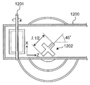
- Patent Document 1 includes an X-shaped circular polarization intersecting on a waveguide 1200 as shown in FIG. A configuration using a wave aperture 1202 is shown.
- Patent Document 2 Japanese Patent No. 3510523 (Patent Document 2), as shown in FIG. 13, two rectangular slit-shaped openings 1301 extending in a direction orthogonal to each other on the waveguide 1300 are opposed to each other. A separate arrangement is shown.
- Patent Document 3 JP-A-2005-235772 (Patent Document 3) includes a patch antenna 1401 coupled to a waveguide 1400 through which microwaves from a magnetron 1404 are transmitted. A configuration is shown in which a circularly polarized wave is generated by forming a notch 1402 in the planar shape of 1401.
- a conventional microwave heating apparatus has a rotatable antenna, an antenna shaft, and the like disposed inside a waveguide. By driving a magnetron while rotating the antenna by an antenna motor, a microwave in the heating chamber is obtained. It had the structure which reduces the nonuniformity of distribution.
- JP-A-62-64093 Patent Document 4
- a rotating antenna is provided at the lower part of the magnetron, and cooling air from the blowing fan is applied to the blades of the rotating antenna, so that the rotating air is rotated by the wind force of the blowing fan.
- a microwave heating apparatus has been proposed in which the antenna is rotated to change the microwave distribution in the heating chamber.
- Patent Document 1 discloses a microwave heating device that reduces heating unevenness of an object to be heated by microwave heating and saves space in a power feeding unit.
- Patent Document 1 proposes a microwave heating apparatus having a rotary phase shifter 1201 and a single microwave radiating unit 1202 that radiates circularly polarized light inside the heating chamber, as shown in FIG. Has been.
- the microwave heating apparatus such as the microwave oven having the above-described conventional configuration
- it is required to have a simple structure as much as possible and to efficiently heat an object to be heated efficiently and uniformly.
- the conventional configurations proposed so far are not satisfactory and have various problems in terms of efficiency and uniformity in terms of structure.
- microwave heating devices especially in microwave ovens, technological development for higher output has progressed, and products with a rated high-frequency output of 1000 W have been commercialized in Japan.
- Microwave ovens are notable for heating food by heat conduction, but the convenience of being able to heat food directly using dielectric heating is a major feature of this product.
- increasing the output in a state where non-uniform heating has not been solved has a big problem that non-uniform heating becomes more obvious.
- the first point requires a drive mechanism for rotating the table or antenna in order to reduce heating unevenness. Therefore, a rotation space for the table or antenna, and a drive source such as a motor for rotating the table or antenna. It was necessary to secure an installation space for preventing the miniaturization of the microwave heating apparatus.
- the second point is that in order to rotate the antenna stably, it is necessary to provide the antenna above or below the heating chamber, which is structurally limited.
- microwave ovens with various heating functions such as steam heating and hot air heating
- many components are required inside the microwave oven housing, which is also structurally limited in this respect. That is.
- the amount of heat generated from the control components inside the housing is large, so it is necessary to secure a cooling air passage inside the housing in order to achieve sufficient cooling performance.
- the installation position of the wave tube and the microwave radiation unit is limited, and there is a problem that the microwave distribution in the heating chamber becomes non-uniform.
- the conventional microwave heating apparatus using circularly polarized waves described above has a problem that in any case of Patent Documents 1 to 3, there is no uniform effect that can make the drive mechanism unnecessary. In any of Patent Documents 1 to 3, it is only described that the synergistic effect of the circularly polarized wave and the drive mechanism can achieve a more uniform structure than the conventional drive mechanism alone.
- the patent document 1 shown in FIG. 12 has a rotating body called a phase shifter 1201 at the end of the waveguide 1200, and the patent document 2 shown in FIG. 13 rotates the object to be heated.
- the patent document 3 shown in FIG. 14 describes a configuration in which the patch antenna 1401 is rotated in addition to the turntable 1403 to be used as a stirrer.
- a drive mechanism can be made unnecessary if circularly polarized waves are used. This is because when a drive mechanism is not provided only by circularly polarized light radiated from a single microwave radiating unit, a configuration having a general drive mechanism, for example, a table on which an object to be heated is placed is rotated. This is because the microwave is not sufficiently stirred as compared with the configuration and the configuration in which the antenna is rotated, so that the uniformity is inferior.
- the present invention solves various problems in the above-described conventional microwave heating apparatus, and an object thereof is to provide a microwave heating apparatus that can uniformly heat an object to be heated without using a drive mechanism.
- a microwave heating apparatus that can uniformly heat an object to be heated without using a drive mechanism.
- the opening cannot be provided outside the width of the waveguide.
- the microwave can be spread in the width direction of the waveguide, and the microwave can be spread in the transmission direction of the microwave in the waveguide. It is possible to make the microwave distribution uniform and provide a configuration capable of uniformly heating an object to be heated.
- the microwave heating apparatus is: A heating chamber for storing an object to be heated; A microwave generator for generating microwaves; A waveguide for transmitting microwaves; A microwave radiating section provided in the waveguide section and radiating microwaves into the heating chamber, wherein a plurality of the microwave radiating sections are arranged in a direction perpendicular to the transmission and electric field direction of the waveguide section. And The centers of at least two of the microwave radiating portions are arranged at positions corresponding to the approximate node positions of the electric field in the waveguide portion. Has been.
- the microwave heating apparatus according to the present invention configured as described above is configured to radiate microwaves into the heating chamber from a plurality of microwave radiating units arranged in a direction perpendicular to the transmission of the waveguide and the electric field direction. Therefore, the microwave spreads mainly in the direction perpendicular to the transmission and electric field direction of the waveguide, and it is possible to radiate the microwave to a region outside the width of the waveguide. As a result, the microwave heating apparatus according to the present invention can make the heating distribution of the object to be heated uniform without using a drive mechanism.
- the spreading direction of the microwave radiated from the microwave radiating portion into the heating chamber is changed according to the phase of the microwave in the waveguide portion at the formation position of the microwave radiating portion, In particular, by arranging the microwave radiating portion at a substantially node position, it is possible to radiate a microwave having directivity in the transmission direction of the waveguide portion.
- a plurality of microwave radiating portions are arranged in a direction perpendicular to the transmission and electric field directions of the waveguide portion, and at least two of these microwave radiating portions are roughly connected.
- a plurality of microwave radiating portions are arranged in a direction perpendicular to the transmission and electric field direction of the waveguide portion, and at least two of these microwave radiating portions are arranged at substantially node positions.
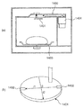
- the perspective view which shows the whole structure of the microwave heating apparatus of Embodiment 1 which concerns on this invention.
- A The top view which shows the waveguide part, microwave radiation
- b The side surface explaining the relationship between a microwave radiation
- the microwave heating apparatus is A heating chamber for storing an object to be heated; A microwave generator for generating microwaves; A waveguide for transmitting microwaves; A microwave radiating section provided in the waveguide section and radiating microwaves into the heating chamber, wherein a plurality of the microwave radiating sections are arranged in a direction perpendicular to the transmission and electric field direction of the waveguide section. And The centers of at least two of the microwave radiating portions are arranged at positions corresponding to the approximate node positions of the electric field in the waveguide portion.
- the microwave heating apparatus configured as described above can mainly spread a microwave in a direction perpendicular to the transmission and electric field direction of the waveguide section, and in the waveguide section. Since the center of at least two microwave radiating portions is arranged at the approximate node position of the electric field, the radiation direction of the microwave radiated from the microwave radiation mainly spreads in the transmission direction of the waveguide portion. Waves can be spread evenly over the heating chamber. Therefore, the microwave heating apparatus according to the first aspect of the present invention has a configuration capable of uniformly heating an object to be heated without using a drive mechanism.
- the centers of at least two of the microwave radiating portions of the first aspect are arranged at substantially the same phase of the electric field in the waveguide. Yes.
- the microwave heating apparatus according to the second aspect of the present invention configured as described above can make the spread of the microwaves from the respective microwave radiating portions substantially the same, and can be heated without a driving mechanism. Things can be heated more uniformly.
- the centers of at least two of the microwave radiating parts of the first aspect or the second aspect are at the same position in the transmission direction of the waveguide part.
- the microwave heating apparatus according to the third aspect of the present invention configured as described above is mainly composed of the transmission of the waveguide section and the electric field as compared with the case where the single microwave radiating section is disposed at the approximate node position. It is possible to obtain a strong microwave spread in a direction perpendicular to the direction.
- a microwave heating apparatus includes at least one microwave radiating unit in the transmission direction of the waveguide unit according to any one of the first to third aspects.
- the distance from the center to the end portion in the transmission direction of the waveguide is an integral multiple of about 1 ⁇ 2 of the guide wavelength in the waveguide.
- the microwave heating apparatus according to the fourth aspect of the present invention configured as described above can accurately and specifically arrange the microwave radiating unit at a substantially node position.
- a microwave heating apparatus has at least one impedance adjustment matching part in the waveguide part according to any one of the first to fourth aspects,
- the distance in the transmission direction of the waveguide section from the center of at least one of the microwave radiation sections to the matching section is an integer multiple of about 1 ⁇ 2 of the guide wavelength in the waveguide section.
- the microwave heating apparatus according to the fifth aspect of the present invention configured as described above can accurately and specifically arrange the microwave radiating unit at a substantially node position.
- a microwave heating apparatus includes at least one impedance adjustment matching section in the waveguide section according to any one of the first to fourth aspects, The center of at least one of the microwave radiating portions is arranged between the matching portion and the end portion in the transmission direction of the waveguide portion in the transmission direction of the waveguide portion.
- the microwave heating apparatus according to the sixth aspect of the present invention configured as described above can accurately and specifically arrange the microwave radiating unit at a substantially node position.
- a microwave heating apparatus includes at least two matching parts in the waveguide part in any one of the first to fourth aspects, and the waveguide The centers of at least one of the microwave radiating portions are arranged between adjacent matching portions in the transmission direction of the portions.
- the microwave heating apparatus configured as described above, in the case of only one matching section, or the distance from the terminal section to the center of the microwave radiating section is the guide wavelength ⁇ g in the waveguide section.
- the microwave radiating portion can be more accurately and specifically arranged at a substantially node position.
- the microwave heating apparatus is from the center of at least one of the microwave radiating units according to any one of the first to seventh aspects to the microwave generating part.
- the distance in the transmission direction of the waveguide is an odd multiple of about 1 ⁇ 4 of the guide wavelength in the waveguide.
- the distance from the matching unit or the terminal unit to the microwave radiating unit, or the distance from the matching unit to the terminal unit is within the waveguide unit.
- the microwave radiating part can be arranged more precisely and specifically at a substantially node position. It becomes.
- a microwave heating apparatus has a configuration in which at least one of the microwave radiating units according to any one of the first to eighth aspects radiates circularly polarized waves. Have.
- the microwave heating device when the microwave radiating portion radiates circularly polarized waves, the microwave heating device is configured so as to wind a vortex from the center of the circularly polarized radiating portions. Since a wave is radiated, the object to be heated can be heated uniformly in the circumferential direction as compared with other microwave radiating means that radiates linearly polarized waves.
- a microwave heating apparatus includes two microwave heating units so that the microwave radiating unit according to any one of the first to eighth aspects radiates circularly polarized waves. It has a substantially X-shaped configuration where the long holes intersect.
- the microwave heating device configured as described above can reliably radiate circularly polarized waves with a simple configuration.
- a microwave oven will be described.
- the microwave oven is an example, and the microwave heating apparatus of the present invention is not limited to the microwave oven, and uses dielectric heating.
- a microwave heating device such as a garbage processing machine or a semiconductor manufacturing device.
- the present invention is not limited to the specific configurations of the following embodiments, and configurations based on similar technical ideas are included in the present invention.
- (Embodiment 1) 1 to 5 are explanatory diagrams relating to a microwave oven that is a microwave heating apparatus according to a first embodiment of the present invention.
- FIG. 1 is a perspective view showing the overall configuration of a microwave heating apparatus 101 that is the microwave oven of the first embodiment.
- FIG. 2A is a view for explaining the positional relationship among the waveguide unit 201, the microwave radiating unit 102, and the microwave generating unit 202 with respect to the heating chamber 103 in the microwave heating apparatus 101.
- FIG. 2B shows the microwave radiating unit 102 in the waveguide unit 201, the phase of the standing wave 204 generated in the waveguide unit 201 (the phase of the electric field 401), and the terminal end of the waveguide unit 201. It is a figure explaining the positional relationship of 203 and the microwave generation part 202.
- FIG. 2A is a view for explaining the positional relationship among the waveguide unit 201, the microwave radiating unit 102, and the microwave generating unit 202 with respect to the heating chamber 103 in the microwave heating apparatus 101.
- FIG. 2B shows the microwave radiating unit 102 in the waveguide unit 201, the phase of the standing wave 204 generated in the wave
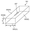
- FIG. 3 is a perspective view for explaining the relationship between the dimensions of a general rectangular waveguide 301 and the transmission mode.
- FIG. 4 is a diagram for explaining the relationship between the electric field 401, the magnetic field 402, and the current 403 generated in the rectangular waveguide unit 201.
- 4A is a plan view showing a generation state of the magnetic field 402 and the current 403 in the waveguide section 201
- FIG. 4B shows a relationship between the electric field 401 and the microwave radiation section 102 in the waveguide section 201. It is a side view.
- FIG. 5 is a figure for demonstrating the relationship between the distance from the termination
- (b) of FIG. FIG. 6 is a diagram for explaining that the spread of the emitted microwaves changes depending on the phase state of the standing wave in the waveguide unit 201 at the position where the microwave emitting unit 102 is provided.
- the results shown in FIG. 5 were obtained by electromagnetic field analysis.
- a microwave heating apparatus 101 includes a heating chamber 103 that can store an object to be heated, a microwave generation unit 202 that generates microwaves, and a microwave that is emitted from the microwave generation unit 202. And a plurality of waveguides 201 that radiate microwaves in the waveguide 201 provided on the H surface of the waveguide 201 (see the H surface 302 of the waveguide 301 in FIG. 3) into the heating chamber 103.
- the microwave radiation part 102 is provided.
- the microwave heating apparatus 101 includes a mounting table 104 on which an object to be heated (not shown) is placed while covering an upper portion of the microwave radiation unit 102, and a door for taking in and out the object to be heated. 105.
- the mounting table 104 is made of a material that easily transmits microwaves, such as glass or ceramic.
- the above configuration can be easily realized by using a magnetron for the microwave generation unit 202, a rectangular waveguide 301 for the waveguide unit 201, and an opening provided in the waveguide unit 201 for the microwave radiation unit 102. it can.
- microwave heating apparatus 101 that is the microwave oven of the first embodiment.
- the microwave heating apparatus 101 When an object to be heated is placed on the mounting table 104 in the heating chamber 103 and a heating start instruction is executed to the microwave heating apparatus 101 by the user, the microwave heating apparatus 101 generates microwaves.
- a microwave is supplied into the waveguide unit 201 from the magnetron that is the unit 202.
- the microwaves When microwaves are supplied from the microwave generation unit 202 into the waveguide unit 201, the microwaves enter the heating chamber 103 via the microwave radiating unit 102 connecting the heating chamber 103 and the waveguide unit 201. Radiated.
- the object to be heated is heated.
- the microwave radiated from the microwave radiating unit 102 and directly heating the object to be heated is called a direct wave
- the microwave reflected by the inner wall of the heating chamber 103 is called a reflected wave.
- the simplest and general waveguide is a rectangular waveguide 301 composed of a rectangular parallelepiped having a certain rectangular cross section (width a ⁇ height b) extending in the transmission direction 207.
- the width a of the waveguide 301 is set such that ⁇ >a> ⁇ / 2. It is known that microwaves are transmitted through the waveguide 301 in the TE10 mode by selecting the range and the height b of the waveguide 301 within the range of b ⁇ / 2.
- the TE10 mode is a transmission in an H wave (TE wave; electrical transverse wave transmission: Transverse Electric Wave) in the rectangular waveguide 301 having only a magnetic field 402 component in the transmission direction 207 and no electric field 401 component. Refers to the mode. Note that transmission modes other than the TE10 mode are rarely applied to the waveguide unit of the microwave oven.
- the wavelength ⁇ of the microwave supplied from the microwave generation unit 202 into the waveguide unit 201 is about 120 mm, and the waveguide unit 201 generally has a width a of about 80 to 100 mm. In many cases, the height b is selected within the range of about 15 to 40 mm.
- the upper and lower surfaces of the rectangular waveguide 301 shown in FIG. 3 are referred to as H surfaces 302 in the sense that the magnetic field 402 spirals in parallel, and the left and right surfaces are referred to as E surfaces in the sense that they are parallel to the electric field 401.
- the guide wavelength ⁇ g varies depending on the width a dimension in the waveguide, but is independent of the height b dimension.
- ⁇ 2 represents the square in the above-described equation indicating the guide wavelength ⁇ g.
- the electric field 401 is 0 at both ends (E surface 303) in the width direction of the waveguide section 201, and the electric field 401 is maximized at the center in the width direction. Therefore, the output part of the magnetron which is the microwave generation part 202 is configured to be coupled to the center in the width direction of the waveguide part 201 where the electric field 401 is maximum.
- micro wave radiated from the waveguide unit 201 to the heating chamber 103 is changed depending on the phase state of the standing wave 204 (electric field 401) generated in the waveguide unit 201 at the formation position where the microwave radiation unit 102 is provided.
- the state of wave spread changes. The principle of changing the spread of the microwave will be described below.
- the relationship between the electric field 401, the magnetic field 402, and the current 403 in the standing wave 204 will be described with reference to FIG.
- the directions of the electric field 401 and the magnetic field 402 are shifted by 90 °, and the phases are the same.
- the directions of the electric field 401 and the magnetic field 402 are shifted by 90 °, and the phase is shifted by ⁇ / 2. Therefore, the relationship between the electric field 401 and the magnetic field 402 in the waveguide section 201 where the standing wave 204 is generated is as shown in FIG.
- the standing wave 204 this is mainly due to the phase of the electric field 401 being shifted by ⁇ / 2 when the traveling wave is reflected by the terminal portion 203 of the waveguide unit 201.
- the current 403 flows on the surface of the waveguide 201 in a direction perpendicular to the magnetic field 402.
- the microwave radiating portion 102 is formed at the approximately antinode position 205 and the approximately nodal position 206 in the standing wave 204 generated in the waveguide portion 201 will be described.
- the antinodes and nodes in the present invention refer to the strength of the electric field 401 in the transmission direction 207 of the waveguide section 201, and the electric field in the direction 209 (see FIG. 4A) perpendicular to the transmission and electric field direction. It does not mean the strength of 401.
- the transmission direction 207 component of the current 403 in the microwave radiating unit 102 and the 209 component in the direction perpendicular to the transmission and electric field direction the current 403 in the microwave radiating unit 102 formed at the substantially antinode position 205 is transmitted.
- the microwave radiated from the waveguide unit 201 to the heating chamber 103 mainly spreads in the direction 209 perpendicular to the transmission and electric field direction.
- the current 403 in the microwave radiating unit 102 formed at the approximate node position 206 has many components in the transmission direction 207. For this reason, the microwave radiated from the waveguide unit 201 to the heating chamber 103 mainly spreads in the transmission direction 207 of the waveguide unit 201.
- FIG. 5 shows the electromagnetic field distribution obtained by computer simulation analysis (CAE).
- the node position of the standing wave 204 is set to phase 0 °, 180 °, 360 °, the antinode position is set to 90 ° and 270 °, and the phase from about 0 ° to about 180 ° in steps of about 45 °.
- the distribution of microwaves radiated from the microwave radiation unit 102 was obtained by electromagnetic field analysis.
- the standing wave in the waveguide 201 is changed at the position where the microwave radiating unit 102 is provided by changing the distance from the terminal end 203 of the waveguide 201 to the center of the microwave radiating unit 102.
- the phase of the electric field 401 of 204 is changed. Note that ⁇ g in FIG. 5 indicates the guide wavelength in the waveguide unit 201.
- the microwave when the phase is about 0 ° (substantially nodal position 206 in FIG. 4B), the microwave is mainly transmitted in the transmission direction 207 in the same manner as described above. Have spread.
- the directivity of the microwave changes counterclockwise, and the phase is about 90 ° (substantially antinode position 205 in FIG. 4B).
- the microwave spreads mainly in a direction 209 perpendicular to the transmission and electric field directions. This is also consistent with the above explanation of the principle.
- the microwave radiating portion 102 at the substantially antinode position 205 in the waveguide portion 201, the microwave can be spread to a region outside the width of the waveguide portion 201. It becomes possible to uniformly heat the object to be heated.
- the microwave generated from the magnetron which is the microwave generation unit, is transmitted in the TE10 mode using the rectangular waveguide 301 shown in FIG.
- the rectangular waveguide 301 in this analysis has a dimension (thickness; height) in the electric field direction 208 of 30 mm, and a dimension (width) in the direction 209 perpendicular to the transmission and electric field direction is 100 mm.
- the frequency of the microwave was 2.46 GHz.
- the moving distance of the microwave radiating unit 102 necessary for changing the spreading direction of the microwave by 90 ° is about half of the in-tube wavelength (about ⁇ g / 4), and the frequency of the microwave used for the analysis is 2 Since it is .46 GHz, the moving distance of the microwave radiating unit 102 required to change the spreading direction of the microwave by 90 ° is about 39.3 mm.
- the shape of the microwave radiating unit 102 used in this analysis was configured such that two slits were orthogonal to each other at the center of each slit and the slit was inclined by 45 ° with respect to the transmission direction 207.
- the number of the microwave radiating portions 102 is one, the length of each slit is 55 mm, and the display data in FIG. 5B is an effective electric field.
- the node position of the standing wave 204 (electric field 401) in the waveguide unit 201 will be described.
- the standing wave 204 is formed in the microwave transmission direction 207. Since the waveguide unit 201 is closed by the terminal end 203, the amplitude at the terminal end 203 is zero. Further, on the supply side (output unit) of the microwave generation unit 202, as shown in FIG. 2B, the amplitude becomes a free end having a maximum value.
- the standing wave 204 existing in the waveguide unit 201 is a wave based on the oscillation frequency supplied by the microwave generation unit 202, and in the present invention, the wavelength of the standing wave 204 is set to the guide wavelength ⁇ g. Call.
- a node position of the standing wave 204 is generated in the waveguide portion 201 with the terminal portion 203 as a base point at every about 1 ⁇ 2 of the guide wavelength ⁇ g. Further, the antinode position of the standing wave 204 exists substantially in the middle of the adjacent node positions.
- the electric field 401 in the waveguide unit 201 around the microwave generation unit 202 is often not stable, and the state of the termination unit 203 is not ideal.
- an in-tube wavelength ⁇ g around the theoretical value is generated. Therefore, it is certain to actually measure the amplitude of the standing wave 204 in the actual accurate waveguide in the waveguide unit 201.
- the mutual interference of the microwaves at an arbitrary point is determined by the difference between the spreading direction of the microwaves from each microwave radiation unit 102 and the distance to the arbitrary point, and the wavelength of the microwaves in the heating chamber 103. .
- it is strengthened when it is an even multiple (including 0) of 1 ⁇ 2 of the wavelength, and weakened when it is an odd multiple.
- the wavelength in air such as in the heating chamber 103 is about 120 mm.
- a plurality of microwave radiating portions 102 are formed at approximately node positions 206, and microwaves having a spread mainly in the transmission direction 207 are radiated from the respective microwave radiating portions 102.
- mutual interference occurs in the heating chamber 103.
- each microwave radiating portion 102 is arranged at a substantially node position 206, the microwave mainly spreads in the transmission direction 207.
- microwave interference in the transmission direction 207 may be mainly considered.
- the microwave interference in the transmission direction 207 is almost the same. Does not occur. Therefore, the spread of the combined wave of the microwaves radiated from the two microwave radiating units 102 is mainly spread in the transmission direction 207, similarly to the spread of the microwaves from the respective microwave radiating units 102.
- each microwave radiating portion 102 having distances in a direction 209 and a transmission direction 207, respectively, perpendicular to the transmission and electric field directions, each arranged at a substantially node position 206. Since each microwave radiating portion 102 is arranged at a substantially node position 206, the microwave mainly spreads in the transmission direction 207. In this case, microwave interference in the transmission direction 207 may be mainly considered.
- each microwave radiating unit 102 is arranged at the approximate node position 206, the spread of the combined microwaves radiated from each microwave radiating unit 102 has a strong directivity mainly in the transmission direction 207. There is no change in having.
- a microwave heating apparatus range 101 that is a microwave oven according to Embodiment 1 includes a heating chamber 103 that stores an object to be heated, a microwave generation unit 202 that generates microwaves, and a waveguide unit 201 that transmits microwaves. And a microwave radiating portion 102 that radiates microwaves in the heating chamber 103, and a plurality of microwave radiating portions 102 are arranged in a direction 209 (width direction) perpendicular to the transmission of the waveguide portion 201 and the electric field direction. ing. Further, each microwave radiating portion 102 is disposed at the approximate node position 206 of the standing wave (electric field 401) in the waveguide portion 201.
- the supply side of the microwave generation unit 202 is a free end indicating the maximum amplitude value as shown in FIG. Therefore, the distance in the transmission direction 207 from the microwave generating unit 202 to the center of the microwave radiating unit 102 is an odd multiple of about 1 ⁇ 4 of the in-tube wavelength ⁇ g in the waveguide unit 201.
- the center position of is approximately the node position 206.
- all the microwave radiating units 102 are disposed at substantially nodal positions, which are the positions where the above distances are achieved.
- the center of the microwave radiating unit 102 indicates a substantial center position of the microwave radiating port. For example, when the microwave radiating unit 102 has an opening shape, the opening In the case where it is assumed that the shape is made of a plate material having the same thickness, the barycentric position of the plate material is shown.
- the configuration of the microwave heating apparatus according to Embodiment 1 radiates microwaves into the heating chamber 103 from the plurality of microwave radiating units 102 arranged in the direction 209 perpendicular to the transmission and electric field direction of the waveguide unit 201. Therefore, the microwave mainly spreads in the direction 209 perpendicular to the transmission and electric field direction of the waveguide 201, and the microwave is radiated to a region outside the width of the waveguide 201. As described above, the microwave is radiated to a region outside the width of the waveguide section 201, so that the microwave heating apparatus according to the first embodiment uniformly heats the object to be heated without using a driving mechanism. It becomes a possible configuration.
- At least two rows of the microwave radiating units 102 are disposed at the respective approximate node positions 206 along the transmission direction of the waveguide unit 201, thereby It becomes possible to radiate microwaves with a spread in each of the direction 209 perpendicular to the transmission and electric field directions and the transmission direction 207, and the heating distribution of the object to be heated can be further improved without using a driving mechanism. It becomes possible to make uniform.
- the distance in the transmission direction 207 from the microwave generation unit 202 to the center of the microwave radiation unit 102 is set to about 1 ⁇ 4 of the in-tube wavelength ⁇ g in the waveguide unit 201.
- a plurality of the microwave radiating portions 102 are arranged in the direction 209 (width direction) perpendicular to the transmission and electric field direction of the waveguide portion 201, and their microwave radiation.
- a configuration is also conceivable in which the portion 102 is disposed at the substantially antinode position 205.
- the transmission of the waveguide unit 201 and the transmission of the waveguide unit 201 are performed by arranging a plurality of them in the direction 209 perpendicular to the transmission and the electric field direction.
- the microwave radiating unit 102 is further disposed at a substantially antinode position 205, so that the direction 209 perpendicular to the transmission of the waveguide unit 201 and the electric field direction is obtained.
- the microwave spreads For this reason, in order to realize uniform heating of the object to be heated, it is necessary to provide more microwave radiation units 102 in the waveguide unit 201 along the transmission direction 207 in the waveguide unit 201.
- the first point is that the mechanical strength of the inner wall of the heating chamber 103 between the heating chamber 103 and the waveguide section 201 is lowered, and there is a risk that the microwave heating apparatus 101 may be damaged due to an impact caused by dropping of an object to be heated. It is to increase.
- the second point is that the microwave radiated from the microwave radiating unit 102 into the heating chamber 103 is reflected by the inner wall of the heating chamber 103 without being absorbed by the object to be heated, and passes through the microwave radiating unit 102 to the waveguide unit 201.
- the amount that comes back in increases.
- the generation state of the standing wave 204 in the waveguide unit 201 is destroyed.
- the position of the microwave radiating unit 102 arranged at the approximately antinode position 205 (and the approximately node position 206) is shifted, and the microwave radiation direction and the radiation amount become unstable.
- the microwave heating apparatus of the present invention as in the configuration shown in FIG. 2, it is not necessary to arrange the centers of all the microwave radiating units 102 at the approximate node positions 206, and at least two microwave radiating units 102. Is arranged at the approximate node position 206 of the electric field 401 in the waveguide section 201, it is included in the present invention. Further, the present invention includes configurations in which the number and positions of the microwave radiating units 102 are asymmetric with respect to the center 210 of the heating chamber 103 and configurations in which the shape of the microwave radiating units 102 is a shape other than a rectangle.
- the present invention includes a configuration in which only two microwave radiating portions 102 are provided and the centers of the two microwave radiating portions 102 are arranged at the approximate node positions 206 of the electric field 401 in the waveguide portion 201. It is what
- FIG. 6 is an explanatory diagram relating to a microwave oven that is the microwave heating apparatus of the second embodiment.
- the same reference numerals are given to portions showing substantially the same functions and operations as those in the first embodiment. Since the basic operation in the second embodiment is the same as the basic operation in the first embodiment, the operation and action of the second embodiment will be described mainly with respect to differences from the first embodiment.
- FIG. 6 illustrates the phase of a standing wave (electric field 401) generated in the microwave radiating unit 102 and the waveguide unit 201 and the positional relationship between the terminal unit 203 of the waveguide unit 201 and the microwave generation unit 202.
- FIG. FIG. 6A is a plan view for explaining the positional relationship among the waveguide unit 201, the microwave radiation unit 102, and the microwave generation unit 202 with respect to the heating chamber 103 in the microwave heating apparatus 101.
- FIG. 6B shows the microwave radiating unit 102 in the waveguide unit 201, the phase of the standing wave 204 generated in the waveguide unit 201 (the phase of the electric field 401), and the termination unit of the waveguide unit 201. It is a side view explaining the positional relationship of 203 and the microwave generation part 202.
- a microwave heating apparatus 101 includes a heating chamber 103 that stores an object to be heated, a microwave generation unit 202 that generates microwaves, a waveguide unit 201 that transmits microwaves, and a heating chamber 103. And a microwave radiating portion 102 for radiating microwaves.
- a plurality of the microwave radiating units 102 in the second embodiment are arranged in a direction 209 (width direction) perpendicular to the transmission of the waveguide unit 201 and the electric field direction.
- Each microwave radiating portion 102 is located at a substantially in-phase position of the electric field 401 in the waveguide portion 201 and is arranged at a substantially node position 206.
- the end portion 203 of the waveguide portion 201 has a substantially nodal position 206 because the amplitude at the end portion 203 is 0 as shown in FIG. . Therefore, the distance in the transmission direction 207 from the terminal end 203 of the waveguide 201 to the center of the microwave radiating unit 102 is a length that is an integral multiple of about 1 ⁇ 2 of the guide wavelength ⁇ g in the waveguide 201.
- the position of the center of the microwave radiating unit 102 is an approximate node position 206.
- each microwave radiating unit 102 has a length that is an integral multiple of about 1 ⁇ 2 of the guide wavelength ⁇ g in the waveguide unit 201 as described above. It is arranged to be.
- the microwave radiating unit 102 has the electric field 401 and the magnetic field when the phase of the electric field 401 in the waveguide unit 201 is different even at the approximate node position 206. Since the direction of 402 is reversed, the main spreading direction of the microwave is also reversed.
- the phase of the electric field 401 of the waveguide unit 201 is approximately the same, and the phase is different by disposing at least two microwave radiating units 102 at approximately the node position 206.
- more uniform heating is possible than in the case where at least two microwave radiating portions 102 are disposed at the approximate node position 206.
- the substantially antinode position 205 and the approximately nodal position 206 do not change with time, and only the directions of the electric field 401 and the magnetic field 402 are reversed every half cycle.
- the microwave heating apparatus is configured such that the microwaves enter the heating chamber 103 from the plurality of microwave radiating units 102 arranged in the direction 209 perpendicular to the transmission and electric field directions of the waveguide unit 201. Is emitted. For this reason, in the microwave heating apparatus of the second embodiment, the microwave spreads mainly in the direction 209 perpendicular to the transmission and electric field direction of the waveguide section 201, and in a region outside the width of the waveguide section 201. Also microwaves are emitted. As a result, the microwave heating apparatus according to the second embodiment can uniformly heat an object to be heated without using a drive mechanism.
- the transmission of the waveguide unit 201 and the electric field direction are arranged by arranging at least two microwave radiating units 102 substantially in phase with the electric field 401 in the waveguide unit 201.
- the microwaves can be radiated more uniformly in each of the perpendicular direction 209 and the transmission direction 207.
- the microwave heating apparatus of the second embodiment can make the heating distribution of the object to be heated more uniform without using a drive mechanism.
- the distance in the transmission direction 207 from the terminal end 203 of the waveguide unit 201 to the center of the microwave radiating unit 102 is set to be approximately equal to the in-tube wavelength ⁇ g in the waveguide unit 201.
- the microwave radiation unit 102 can be accurately and specifically arranged at the approximate node position 206.
- all the microwave radiating portions are arranged at substantially the same phase position of the electric field 401 in the waveguide portion 201 as in the microwave radiating portion 601 shown in FIG.
- the microwave radiating unit 601 shown in FIG. 6 is at a position substantially in the same phase of the electric field 401 in the waveguide 201 and is different from the plurality of microwave radiating units 102 at the position of the approximate node position 206.
- the example is arranged at another position different from the microwave radiation unit 102. As shown in FIG.
- the other microwave radiating portions 601 are the microwave radiating portions 102.
- Configurations arranged at positions different from the above are also included in the present invention.
- the number and arrangement of the microwave radiating units 102 are not limited to the configuration of the second embodiment, and the specification and configuration of the microwave heating device are taken into consideration. It is set appropriately. Further, regarding the arrangement of the microwave radiating portion 102, the case where the microwave radiating portion 102 is asymmetric with respect to the center 210 of the heating chamber (see FIG. 6A), and the shape of the microwave radiating portion is shown in FIG. In the case other than the ellipse shown in FIG. 4, the same effect is obtained and included in the present invention.
- FIGS. 7 and 8 are explanatory diagrams relating to a microwave oven that is the microwave heating apparatus of the third embodiment. 7 and FIG. 8, the same reference numerals are given to the portions showing substantially the same functions and operations as those of the first and second embodiments.
- the basic operation in the third embodiment is the same as the basic operation in the first and second embodiments. Therefore, the third embodiment mainly operates at different points from the other embodiments. The operation will be described.
- FIG. 7 shows the positional relationship between the microwave radiating unit 102 and the phase of the standing wave (electric field 401) generated in the waveguide 201 in the microwave heating apparatus 101 of Embodiment 3, and the waveguide 201 It is a figure explaining the positional relationship of the termination
- 7A shows the positional relationship of the waveguide unit 201, the microwave radiating unit 102, the microwave generating unit 202, and the impedance adjusting matching unit 701 with respect to the heating chamber 103 in the microwave heating apparatus 101.
- FIG. 7B illustrates the microwave radiating unit 102 in the waveguide unit 201, the phase of the standing wave 204 generated in the waveguide unit 201 (the state in which the electric field 401 is generated), and the termination of the waveguide unit 201.
- 6 is a side view for explaining the positional relationship among a unit 203, a matching unit 701, and a microwave generation unit 202.
- the microwave radiation part 102 in the microwave heating apparatus 101 of Embodiment 3 As the shape of the microwave radiation part 102 in the microwave heating apparatus 101 of Embodiment 3, it has the shape where two slits cross
- FIG. 8A shows the distance from the impedance adjusting matching section 701 provided in the waveguide section to the center of the microwave radiating section 102 and the phase of the standing wave (electric field 401) in the waveguide section 201. It is a figure for demonstrating the relationship.
- FIG. 8B shows that the directivity of the emitted microwave changes depending on the phase state of the standing wave (electric field 401) in the waveguide section 201 at the position where the microwave radiation section 102 is provided. It is a figure for demonstrating.
- the matching portion 701 when the matching portion 701 is disposed at the approximate node position 206 in the waveguide portion 201, the amplitude becomes 0 at the position of the matching portion 701, and the approximate node position 206 of the electric field 401 in the phase of the standing wave 204 is obtained.
- the alignment portion 701 is reliably formed.
- a cylindrical metal is used as the matching portion 701, and the metal surface plays the same role as the fixed end.
- the matching portion 701 at the approximate node position 206 of the electric field 401, a state in which the microwave is radiated from the microwave radiating portion 102 into the heating chamber 103 and the electric field distribution in the waveguide portion 201 is broken.
- the substantially antinode position 205 and the approximate node position 206 in the waveguide section 201 it is possible to fix the substantially antinode position 205 and the approximate node position 206 in the waveguide section 201 to stable positions.
- another cause of the collapse of the electric field distribution in the waveguide unit 201 is that the microwave reflected by the inner wall of the heating chamber 103 returns to the waveguide unit 201 through the microwave radiation unit 102. Is mentioned.
- the matching section 701 is provided at a predetermined position in the waveguide section.
- the substantially antinode position 205 and the approximately nodal position 206 of the electric field 401 are stably formed at predetermined positions.
- the matching portion 701 By the action of the matching portion 701 provided as described above, the symmetry axis of the intersection point between the microwave radiation portion 102 and the wall current 403 (see FIG. 4A) of the waveguide portion 201 is stabilized. For this reason, when the microwave radiating unit 102 blocks the wall current 403 of the waveguide unit 201, the spread of the microwave radiated from the microwave radiating unit 102 into the heating chamber 103 can be stabilized.
- the waveguide section maintained by the matching section 701 is set by setting the interval between adjacent matching sections 701 to about 1 ⁇ 2 of the guide wavelength ⁇ g in the waveguide section 201.
- the electric field distribution in 201 can be reasonably formed at a wavelength at which it easily exists. For this reason, in the microwave heating apparatus 101 which is the microwave heating apparatus of Embodiment 3, microwave transmission with high efficiency is possible, and highly efficient and stable microwave heating is possible.
- the amplitude is 0 at the position of the matching portion 701 and is substantially the node position 206
- the integral multiple of about 1 ⁇ 2 of the guide wavelength ⁇ g in the waveguide portion 201 from the matching portion 701 is obtained.
- the approximate node position 206 exists at the position. Therefore, by measuring the distance from the matching unit 701, the position for disposing the microwave radiating unit 102 at the approximate node position 206 can be easily and reliably determined.
- the matching unit 701 is arranged at the center (on the central axis 211) in the direction 209 (width direction) perpendicular to the transmission and electric field direction of the waveguide unit 201 is shown. Even if the portion 701 is displaced from the center of the waveguide portion 201 in the width direction, the same effect can be obtained.
- the matching portion 701 since the cylindrical metal is used as the matching portion 701, the matching portion 701 can be easily realized.
- the matching unit 701 may be configured to create a point where the amplitude is zero.
- FIG. 8A shows the distance [ ⁇ ⁇ g] from the matching unit 701 to the center of the microwave radiating unit 102 and the phase [deg.] Of the standing wave (electric field 401) in the waveguide unit 201. It is a figure for demonstrating a relationship.
- (B) of FIG. 8 is for demonstrating that the spread of the radiated microwave is changed by the phase state of the standing wave in the waveguide 201 at the position where the microwave radiating unit 102 is provided.
- FIG. As for the result shown in FIG. 8, the electromagnetic field distribution was obtained by computer simulation analysis (CAE).
- FIG. 8 The description regarding FIG. 8 is the same as the description of FIG. 5 of the first embodiment described above, and every time the distance from the matching unit 701 to the center of the microwave radiating unit 102 becomes approximately 1/8 of the guide wavelength ⁇ g,
- the phase of the electric field 401 in the waveguide 201 changes by about 45 °, and the main spreading direction of the microwave radiated into the heating chamber 103 also changes in accordance with the phase of the electric field 401 in the waveguide 201. It is shown that.
- a microwave heating apparatus 101 that is a microwave heating apparatus of Embodiment 3 includes a heating chamber 103 that stores an object to be heated, a microwave generation unit 202 that generates a microwave, and a microwave. , A matching unit 701 for adjusting impedance, and a microwave radiating unit 102 that radiates microwaves into the heating chamber 103.
- a plurality of microwave radiating portions 102 in the third embodiment have a predetermined distance along a direction 209 (width direction of the waveguide portion 201) perpendicular to the transmission and electric field direction of the waveguide portion 201 (the embodiment). 2 are arranged in 3).
- each microwave radiating portion 102 is disposed at the approximate node position 206 of the electric field 401 in the waveguide portion 201.
- the microwave radiating unit 102 is disposed between the terminal end 203 of the waveguide unit 201 and the matching unit 701. ing. This is because the amplitude of the electric field 401 in the waveguide section 201 at the termination section 203 and the matching section 701 of the waveguide section 201 is 0, so that the positions of the termination section 203 and the matching section 701 become the approximate node position 206. This is because the microwave radiating unit 102 is disposed at a substantially nodal position 206 generated between the terminal end 203 of the unit 201 and the matching unit 701. Further, the microwave radiating unit 102 is disposed at a substantially node position 206 where the distance from the matching unit 701 is an integral multiple of about 1 ⁇ 2 of the guide wavelength ⁇ g in the waveguide unit 201.
- the plurality of microwave radiating portions 102 are arranged so as to have a distance only in the direction 209 (width direction) perpendicular to the transmission and electric field direction of the waveguide portion 201, so that the single microwave radiating portion 102 Compared with the case where microwaves are radiated, it is possible to obtain a strong microwave spread mainly in the direction 209 perpendicular to the transmission of the waveguide unit 201 and the electric field direction.
- the microwave heating apparatus 101 according to the third embodiment a plurality of microwave radiating units 102 are arranged in a direction 209 perpendicular to the transmission and electric field direction of the waveguide unit 201, thereby A microwave is emitted from the radiating unit 102 into the heating chamber 103.
- the microwave heating apparatus 101 according to the third embodiment has a configuration in which microwaves spread mainly in the direction 209 perpendicular to the transmission of the waveguide section 201 and the electric field direction.
- the microwave heating apparatus 101 according to the third embodiment can radiate microwaves to a region outside the width of the waveguide section 201, and the object to be heated can be used without using a driving mechanism. The heating distribution can be made uniform.
- the distance from the matching unit 701 to the center of the microwave radiating unit 102 in the transmission direction 207 of the waveguide unit 201 is set to the wavelength ⁇ g in the waveguide unit 201.
- the microwave radiating unit 102 can be accurately and specifically set to be an integral multiple of about 1 ⁇ 2.
- the radiating portion 102 can be disposed at the approximate node position 206 in the waveguide portion 201.
- microwave heating apparatus of the present invention it is not necessary to arrange all the microwave radiating portions 102 at the approximate node positions 206 as in the configuration shown in FIG. Unit 102 in transmission direction 207, between termination unit 203 of waveguide unit 201 and matching unit 701, and / or an integral multiple of about 1 ⁇ 2 of guide wavelength ⁇ g in waveguide unit 201 from matching unit 701. If it is the structure arrange
- the number, arrangement, and shape of the microwave radiating portions are not limited to the configuration of the third embodiment, and the specification and configuration of the microwave heating apparatus are taken into consideration. It is set appropriately.
- the arrangement of the microwave radiating portion the case where the microwave radiating portion is asymmetric with respect to the center 210 of the heating chamber (see FIG. 7A) or the shape of the microwave radiating portion is as shown in FIG. The same effect can be obtained even in a case other than the shape in which two slits are crossed as shown in the figure, and is included in the present invention.
- FIG. 9 is an explanatory diagram of a microwave oven that is the microwave heating apparatus according to the fourth embodiment.
- the same reference numerals are given to portions showing substantially the same functions and operations as in the first to third embodiments.
- the basic operation in the fourth embodiment is the same as the basic operation of the microwave heating apparatus in the first to third embodiments. Therefore, the fourth embodiment is different from the other embodiments. The operation and action will be mainly described.
- FIG. 9 shows the phase of the standing wave (electric field 401) generated in the microwave radiating unit 102 and the waveguide unit 201, and the terminal unit 203 and the microwave generating unit 202 of the waveguide unit 201 and the matching unit for impedance adjustment.
- 7 is a diagram for explaining a positional relationship with 701.
- FIG. (A) of FIG. 9 is the position of the waveguide part 201, the microwave radiation
- FIG. (A) of FIG. 9 is the position of the waveguide part 201, the microwave radiation
- FIG. (A) of FIG. 9 is the position of the waveguide part 201, the microwave
- FIG. 9B illustrates the microwave radiating unit 102 in the waveguide unit 201, the phase of the standing wave 204 generated in the waveguide unit 201 (the phase of the electric field 401), and the terminal end of the waveguide unit 201. It is a side view explaining the positional relationship of 203, the matching part 701, and the microwave generation part 202.
- FIG. 9B illustrates the microwave radiating unit 102 in the waveguide unit 201, the phase of the standing wave 204 generated in the waveguide unit 201 (the phase of the electric field 401), and the terminal end of the waveguide unit 201. It is a side view explaining the positional relationship of 203, the matching part 701, and the microwave generation part 202.
- the microwave heating apparatus 101 includes a heating chamber 103 that stores an object to be heated, a microwave generator 202 that generates a microwave, and a waveguide that transmits the microwave. 201, a matching unit 701 for impedance adjustment, and a microwave radiating unit 102 that radiates microwaves into the heating chamber 103.
- a plurality of the microwave radiating units 102 according to the fourth embodiment are arranged so as to have a distance only in a direction 209 (width direction) perpendicular to the transmission of the waveguide unit 201 and the electric field direction.
- Each microwave radiating portion 102 is disposed at a substantially node position 206 of the electric field 401 in the waveguide portion 201.
- the microwave radiating unit 102 has a distance from the matching unit 701 of about 1 ⁇ 2 of the in-tube wavelength ⁇ g in the waveguide unit 201. It is arranged at the approximate node position 206 that is an integral multiple of.
- emission part 102 has a shape which has arrange
- the microwave radiation part 102 in Embodiment 4 is a structure which radiates
- a metal hemispherical matching portion 701 is disposed at a substantially node position in the waveguide portion 201.
- the matching part 701 is arranged in this way, the amplitude becomes zero at the position of the matching part 701, and the approximate node position 206 of the electric field 401 in the phase of the standing wave 204 is reliably formed in the matching part 701.
- the inside of the heating chamber 103 includes the plurality of microwave radiating units 102 arranged along the direction 209 perpendicular to the transmission and electric field directions of the waveguide unit 201. Therefore, the microwave spreads mainly in the direction 209 perpendicular to the transmission and electric field direction of the waveguide 201, and also in the region outside the width of the waveguide 201. A configuration in which microwaves are emitted. Therefore, in the microwave heating apparatus of the fourth embodiment, the heating distribution of the object to be heated can be made uniform without using a drive mechanism.
- the distance in the transmission direction 207 from the matching unit 701 to the center of the microwave radiating unit 102 is an integer of about 1 ⁇ 2 of the in-tube wavelength ⁇ g in the waveguide unit 201.
- the microwave heating apparatus of the fourth embodiment even if the microwave radiating unit 601 is provided substantially at the abdominal position, at least two microwave radiating units 102 are included in the matching unit 701.
- the present invention includes any configuration that is disposed at a substantially node position that is an integral multiple of about 1 ⁇ 2 of the in-tube wavelength ⁇ g in the waveguide section 201.
- the number, arrangement, and shape of the microwave radiating units 102 are not limited to the configuration of the fourth embodiment, and are appropriately set in consideration of the specification, configuration, and the like of the microwave heating device. Further, regarding the arrangement of the microwave radiating portion, the case where it is asymmetric with respect to the center 210 of the heating chamber (see FIG.
- FIG. 10 shows the positional relationship between the microwave radiating unit 102 and the phase of the standing wave (electric field 401) generated in the waveguide unit 201 in the microwave heating apparatus 101 of Embodiment 5, and the waveguide unit 201. It is a figure explaining the positional relationship of the termination
- (A) of FIG. 10 shows the positional relationship between the waveguide section 201, the microwave radiation sections 102 and 601, the matching section 701, and the microwave generation section 202 with respect to the heating chamber 103 in the microwave heating apparatus 101. It is a top view to explain.
- FIG. 10B shows the phase of the microwave radiating units 102 and 601 and the standing wave 204 generated in the waveguide unit 201 (the state in which the electric field 401 is generated) in the waveguide unit 201, and the waveguide unit 201. It is a side view explaining the positional relationship of the terminal part 203 of this, the matching part 701, and the microwave generation part 202.
- FIG. 10B shows the phase of the microwave radiating units 102 and 601 and the standing wave 204 generated in the waveguide unit 201 (the state in which the electric field 401 is generated) in the waveguide unit 201, and the waveguide unit 201. It is a side view explaining the positional relationship of the terminal part 203 of this, the matching part 701, and the microwave generation part 202.
- Circular polarization is a technology widely used in the fields of mobile communications and satellite communications. Familiar use examples include ETC (Electronic Toll Collection System) “Non-stop automatic toll collection system”. Circular polarization is a microwave in which the polarization plane of the electric field 401 rotates with respect to the traveling direction of the radio wave, and when the circular polarization is formed, the direction of the electric field 401 continues to change with time. The microwave radiation angle radiated into the chamber 103 also keeps changing, and the electric field strength does not change with time.
- ETC Electronic Toll Collection System
- Non-stop automatic toll collection system Non-stop automatic toll collection system
- the microwave heating according to the present invention having the microwave radiating portions 102 and 601 that radiate circularly polarized waves is compared with the microwave heating by linearly polarized waves used in the conventional microwave heating apparatus.
- microwaves are dispersed and radiated over a wide range, and the object to be heated can be heated uniformly.
- circularly polarized waves are classified into two types from the direction of rotation: right-handed polarization (CW: Clockwise) and left-handed polarization (CCW: Counter Clockwise), but there is no difference in heating performance.
- the microwaves in the waveguide section are linearly polarized waves whose electric field and magnetic field vibration directions are constant.
- a mechanism for rotating the table on which the object is to be heated or a heating from the waveguide section is used. It is necessary to install a mechanism that rotates an antenna that radiates microwaves to the room.
- the microwave heating apparatus of the fifth embodiment since it is configured to radiate circularly polarized microwaves from the waveguide unit 201 into the heating chamber 103, the conventional microwave heating apparatus using linearly polarized waves It is possible to alleviate the standing wave generated in the heating chamber due to the interference between the direct wave and the reflected wave, which has been a problem in the microwave heating by the above, and uniform microwave heating can be realized.
- the circularly polarized wave in the present invention does not mean only when the microwave spread from the microwave radiating units 102 and 601 is an exact perfect circle, but the microwave spread is an ellipse. It also includes cases such as. That is, in the present invention, the direction of the electric field 401 continues to change with time, so that the radiation angle of the microwave radiated into the heating chamber 103 also changes, and the magnitude of the electric field strength changes with time. Those having the characteristic of not being defined are defined as circularly polarized waves.
- a heated object such as food with no directivity is configured to receive microwaves, so it is only important that the microwaves hit the entire area evenly. Become.
- the object to be heated may be arranged directly above the circularly polarized aperture, but it is arranged at a position shifted before or after the circularly polarized aperture or left and right.
- similar to a circularly polarized-wave opening will be easy to be heated, and a far site
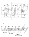
- a plurality of circularly polarized apertures that are the microwave radiating portions 102 and 601 extend along the transmission direction 207 of the waveguide portion 201. Are formed side by side, and two are formed side by side along the direction 209 perpendicular to the transmission and electric field direction of the waveguide section 201, and a total of 10 circularly polarized apertures are arranged.
- the circularly polarized apertures (microwave radiation units 102 and 601) arranged in two along the perpendicular direction 209 have opposite polarization directions (right-handed polarization or left-handed polarization). Arrangement is unthinkable in the communication field, and is the first configuration realized in the present invention, and is a special arrangement unique to the heating field.
- the microwave radiating portions 102 and 601 are arranged in a direction 209 (width) perpendicular to the transmission and electric field direction of the waveguide portion 201. A plurality (two) of them are formed at a distance along the (direction), and are arranged at the approximate node position 206 of the electric field 401 in the waveguide section 201.
- the microwave radiating portion 601 is a microwave radiating portion formed at a position other than between adjacent matching portions 701.
- the microwave radiating portions 102 and 601 that radiate circularly polarized waves have a positive X-shaped configuration in which two long holes (slits) intersect with each other. With this configuration, it is possible to reliably radiate circularly polarized waves with a simple configuration.
- the microwave radiating portions 102 and 601 are configured by inclining long holes (slits) without being orthogonal to each other, and are formed in an X-shape.
- the shape may be a collapsed X shape that is crushed so as to be long in the horizontal direction (transmission direction 207). Even when the crushed X-shaped microwave radiation portions 102 and 601 are crushed in this manner, the spread of the microwave is deformed from a perfect circle to become an ellipse, but it is possible to radiate circularly polarized waves.
- the center of the microwave radiating portions 102 and 601 can be brought closer to the end portion (left and right side walls) of the waveguide portion 201 without reducing the length of the circularly polarized aperture.
- the microwave can be further spread mainly in the direction 209 perpendicular to the transmission of the waveguide 201 and the electric field direction, and the object to be heated can be uniformly heated without using a driving mechanism.
- the following three points can be given as conditions for the best shape of the microwave radiation portions 102 and 601 that radiate circularly polarized waves constituted by two long holes (slits).
- the first point is that the length of the long side of each slit is about 1/4 or more of the guide wavelength ⁇ g in the waveguide section 201.
- the second point is that the two slits are orthogonal to each other and that the long side of each slit is inclined (for example, 45 °) with respect to the transmission direction 207.
- the third point is that the distribution of the electric field 401 is not an axis contrast with a straight line that is parallel to the transmission direction 207 of the waveguide unit 201 and passes through the center of the microwave radiation unit 102 as an axis.
- the electric field 401 is distributed with the central axis 211 (see FIG. 10A) in the transmission direction 207 in the waveguide unit 201 as the axis of symmetry. It is a condition that the shapes of the microwave radiating units 102 and 601 are arranged so as not to be axially targeted with respect to the central axis 211 in the transmission direction 207 in the waveguide unit 201.
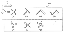
- FIGS. 11A to 11G are plan views showing examples of the shapes of the microwave radiating portions 102 and 601 that radiate circularly polarized waves used in the present invention.
- the microwave radiating portions 102 and 601 that radiate circularly polarized waves are configured by two or more slits, and at least one of them is formed. It suffices if the long side of the slit is inclined with respect to the microwave transmission direction 207. Therefore, a shape in which the slits do not intersect as shown in FIGS. 11E and 11F or a shape constituted by three slits as shown in FIG. 11D may be used.
- the microwave radiating unit 102 can be configured in a T-shape or an X-shape by a plurality of linear slits. . For this reason, it can be applied when the slits are arranged apart from each other as in the above-mentioned Patent Document 2 shown in FIG. Further, as shown in FIG. 13B, as the microwave radiating portion 102, the two slits do not have to be orthogonal to each other.
- the axis parallel to the transmission direction 207 of the waveguide unit 201 or the transmission of the waveguide unit 201 it is possible to radiate circularly polarized waves even in a microwave radiation portion having a shape that is not axially symmetric with respect to an axis parallel to the direction 209 perpendicular to the electric field direction.
- the opening shape of the long hole (slit) constituting the microwave radiating portion 102 in the fifth embodiment is not limited to a rectangle.
- circularly polarized aperture it can be inferred that it is only necessary to combine two elongated apertures that are longer in one direction and shorter in the direction orthogonal to the one direction.
- the microwave heating apparatus 101 includes a heating chamber 103 that stores an object to be heated, a microwave generation unit 202 that generates microwaves, and a waveguide unit that transmits microwaves. 201, a plurality of impedance adjusting matching sections 701, and microwave radiating sections 102 and 601 that radiate microwaves that radiate circularly polarized waves into the heating chamber 103.
- a plurality of the microwave radiation units 102 and 601 in the fifth embodiment are arranged so as to have a distance in the direction 209 (width direction) perpendicular to the transmission of the waveguide unit 201 and the electric field direction.
- the microwave radiating portions 102 and 601 are disposed at the approximate node positions 206 of the electric field 401 in the waveguide portion 201.
- the microwave radiating unit 102 is provided between the matching unit 701 and the matching unit 701 having a distance of at least one wavelength. Is arranged.
- the position of the matching unit 701 is a position where the amplitude of the electric field 401 in the waveguide unit 201 is 0, which is a substantially node position 206. For this reason, the microwave radiating part 102 is disposed at a substantially nodal position 206 generated between adjacent matching parts 701 having a distance of at least one wavelength.
- the magnetic fields 402 that are the upper and lower surfaces of the waveguide unit 301 shown in FIG.
- An opening having a predetermined shape is formed in the H surface 302 of the swirling surface, and the circularly polarized wave is configured to be reliably radiated to the heating chamber 103.
- the heating by the circularly polarized wave can be uniformly heated in the circumferential direction as compared with the linearly polarized wave.
- the arrangement of the vortices is opposite to each other by arranging them symmetrically about the central axis 211 parallel to the direction 209 perpendicular to the transmission and electric field direction of the waveguide 201, so that the center of the waveguide 201 is reversed.
- the direction on the side will be the same direction and will not cancel each other. Therefore, the microwave radiated from the waveguide unit 201 into the heating chamber can be expanded without being wasted.
- the microwave heating apparatus As described above, in the microwave heating apparatus according to the fifth embodiment of the present invention, a plurality of microwaves arranged at a distance along the direction 209 perpendicular to the transmission and electric field directions of the waveguide section 201.
- the microwave is radiated from the radiating unit 102 into the heating chamber 103.
- the microwave spreads in the direction 209 perpendicular to the transmission and electric field direction of the waveguide section 201, and the microwave is spread in a region outside the width of the waveguide section 201. A wave is emitted.
- the microwave heating apparatus of the fifth embodiment can make the heating distribution of the object to be heated uniform without using a drive mechanism.
- the microwave heating apparatus has at least two matching portions 701, and is positioned between adjacent matching portions 701 and 701 in the transmission direction 207 of the waveguide portion 201. At least one microwave radiation unit 102 is arranged.
- the distance from one matching unit to the microwave radiating unit is microscopic so that it is an integral multiple (including 0 times) of about 1 ⁇ 2 of the guide wavelength ⁇ g in the waveguide unit.
- the microwave heating apparatus of the fifth embodiment can more accurately and specifically arrange the microwave radiating part 102 at the approximate node position 206 more reliably. Become.
- the microwave radiating portion is located above the matching portion. To do.
- the microwave radiating units 102 and 601 radiate circularly polarized waves so that a vortex is wound from the center of the circularly polarized radiating parts. Since microwaves are radiated, uniform heating is possible as compared with a conventional microwave radiating unit that radiates linearly polarized waves. In particular, in the configuration of the microwave heating apparatus of the fifth embodiment, it can be expected that the object to be heated is uniformly heated in the circumferential direction by the microwave radiating unit 102 that radiates circularly polarized waves.
- the microwave radiating portions 102 and 601 that radiate circularly polarized waves have a substantially X-shaped configuration in which two long holes (slits) intersect. By doing so, circularly polarized waves can be reliably radiated with a simple configuration.
- microwave heating apparatus of the present invention it is not necessary to arrange all the microwave radiating portions 102 at the approximate node positions 206, and at least 2 As long as two microwave radiating portions 102 are arranged between adjacent matching portions 701 and matching portions 701, the same effects as in the configuration of the fifth embodiment are obtained and included in the present invention.
- the number and position of the microwave radiating portions are not limited to the configuration of the fifth embodiment, and are appropriately set in consideration of the specification and configuration of the microwave heating apparatus. It is what is done. Further, regarding the arrangement of the microwave radiating portion, the present invention includes a case where the arrangement is asymmetric with respect to the center 210 of the heating chamber (see FIG. 10A).
- microwave heating device of the present invention at least two microwave radiating portions that radiate circularly polarized waves are disposed at substantially node positions, and the microwave radiating portions are arranged in the transmission and electric field directions of the waveguide portion. If it is arranged in a direction perpendicular to it, the heating distribution of the object to be heated can be made uniform without providing a drive mechanism.
- the microwave heating apparatus includes a heating chamber that houses an object to be heated, a microwave generation unit that generates microwaves, a waveguide unit that transmits microwaves, and the waveguide unit.
- a microwave radiating section that radiates microwaves into the heating chamber, and a plurality of the microwave radiating sections are arranged in a direction perpendicular to the transmission and electric field direction of the waveguide section, and at least The centers of the two microwave radiating portions are arranged at positions corresponding to the approximate node positions of the electric field in the waveguide portion.
- the microwave heating apparatus according to the present invention configured as described above is configured to radiate microwaves into the heating chamber from a plurality of microwave radiating units arranged in a direction perpendicular to the transmission of the waveguide and the electric field direction. Therefore, the microwave spreads mainly in the direction perpendicular to the transmission and electric field direction of the waveguide, and it is possible to radiate the microwave to a region outside the width of the waveguide. As a result, the microwave heating apparatus according to the present invention can make the heating distribution of the object to be heated uniform without using a drive mechanism.
- the microwave heating apparatus changes the direction in which the microwave radiated from the microwave radiating portion into the heating chamber changes depending on the phase of the microwave in the waveguide portion at the position of the microwave radiating portion.
- a plurality of microwave radiating portions are arranged in a direction perpendicular to the transmission and electric field directions of the waveguide portion, and at least two of these microwave radiating portions are roughly connected.
- microwave heating apparatus by providing a microwave radiating portion that radiates circularly polarized waves, microwaves having a spread characteristic of circularly polarized waves are radiated from the microwave radiating portions.
- the microwave radiation to the object to be heated can be made uniform over a wider range.
- microwave heating by circular polarization can be expected to be uniform in the circumferential direction.
- the microwave radiating part that radiates circularly polarized waves has a simple shape constituted by two or more slits. Therefore, it is possible to improve the reliability and reduce the size of the power feeding unit with a simple configuration without using a drive mechanism.
- the microwave heating apparatus of the present invention can uniformly irradiate an object to be heated, it can be effectively used for a heating apparatus that performs heating processing or sterilization of individual foods.
- Microwave heating device microwave oven
- 601 Microwave radiation part Heating chamber
- 201 Waveguide part 202
- Microwave generation part 203
- Termination part 205
- Substantially antinode position 206
- Substantially node position 207 Transmission direction 209
- Direction perpendicular to transmission and electric field direction 401
- Electric field 402 Magnetic field 403 Current 701 Alignment part
Abstract
Description
被加熱物を収納する加熱室と、
マイクロ波を発生するマイクロ波発生部と、
マイクロ波を伝送する導波部と、
前記導波部に設けられ、前記加熱室内にマイクロ波を放射するマイクロ波放射部と、を備え
前記マイクロ波放射部が、前記導波部の伝送および電界方向に対して直角方向に複数配置されており、
少なくとも2つの前記マイクロ波放射部の中心が、前記導波部内の電界の略節位置に対応する位置に配置されている。
されている。 In order to solve the problems in the above-described conventional microwave heating apparatus, the microwave heating apparatus according to the present invention is:
A heating chamber for storing an object to be heated;
A microwave generator for generating microwaves;
A waveguide for transmitting microwaves;
A microwave radiating section provided in the waveguide section and radiating microwaves into the heating chamber, wherein a plurality of the microwave radiating sections are arranged in a direction perpendicular to the transmission and electric field direction of the waveguide section. And
The centers of at least two of the microwave radiating portions are arranged at positions corresponding to the approximate node positions of the electric field in the waveguide portion.
Has been.
被加熱物を収納する加熱室と、
マイクロ波を発生するマイクロ波発生部と、
マイクロ波を伝送する導波部と、
前記導波部に設けられ、前記加熱室内にマイクロ波を放射するマイクロ波放射部と、を備え
前記マイクロ波放射部が、前記導波部の伝送および電界方向に対して直角方向に複数配置されており、
少なくとも2つの前記マイクロ波放射部の中心が、前記導波部内の電界の略節位置に対応する位置に配置されている。 The microwave heating apparatus according to the first aspect of the present invention is
A heating chamber for storing an object to be heated;
A microwave generator for generating microwaves;
A waveguide for transmitting microwaves;
A microwave radiating section provided in the waveguide section and radiating microwaves into the heating chamber, wherein a plurality of the microwave radiating sections are arranged in a direction perpendicular to the transmission and electric field direction of the waveguide section. And
The centers of at least two of the microwave radiating portions are arranged at positions corresponding to the approximate node positions of the electric field in the waveguide portion.
図1~図5は、本発明に係る実施の形態1のマイクロ波加熱装置である電子レンジに関する説明図である。 (Embodiment 1)
1 to 5 are explanatory diagrams relating to a microwave oven that is a microwave heating apparatus according to a first embodiment of the present invention.
実施の形態1のマイクロ波加熱装置101は、被加熱物を収納可能な加熱室103と、マイクロ波を発生させるマイクロ波発生部202と、マイクロ波発生部202から放射されたマイクロ波を加熱室103に導く導波部201と、導波部201のH面(図3の導波管301のH面302参照)に設けた導波部201内のマイクロ波を加熱室103内に放射する複数のマイクロ波放射部102と、を有している。 <Configuration of microwave heating device>
A
最初に、実施の形態1の電子レンジであるマイクロ波加熱装置101の概略動作について説明する。使用者により加熱室103内の載置台104上に被加熱物が載置され、当該マイクロ波加熱装置101に対して加熱開始指示が実行されると、マイクロ波加熱装置101においては、マイクロ波発生部202であるマグネトロンから導波部201内にマイクロ波が供給される。マイクロ波発生部202から導波部201内にマイクロ波が供給されると、加熱室103と導波部201とを連結しているマイクロ波放射部102を介して加熱室103内にマイクロ波が放射される。この結果、マイクロ波加熱装置101においては当該被加熱物に対する加熱が行われる。 <Schematic operation of microwave heating device>
First, a schematic operation of the
本発明において、マイクロ波放射部102から放射され被加熱物を直接加熱するマイクロ波を直接波と呼び、加熱室103の内壁等で反射したマイクロ波を反射波と呼ぶ。 <Definition of indirect and direct waves>
In the present invention, the microwave radiated from the
次に、図3を用いて電子レンジなどに搭載される代表的な導波部である矩形導波管301について説明する。最も単純で一般的な導波管は、図3に示すように、一定の長方形の断面(幅a×高さb)を伝送方向207に延ばした直方体で構成された矩形導波管301である。このような構成の矩形導波管301において、当該矩形導波管301に供給されるマイクロ波の波長をλとしたときに、導波管301の幅aを、λ>a>λ/2の範囲内、および導波管301の高さbを、b<λ/2の範囲に選ぶことにより、TE10モードでマイクロ波が導波管301内を伝送することが知られている。 <Description of rectangular waveguide dimensions and TE10 mode>
Next, a
次に、図2に示すように、導波部201として矩形導波管301(図3参照)を用いている場合、マイクロ波発生部202からの進行波と、導波部201の終端部203で反射した反射波とが互いに干渉して、導波部201内に定在波204が生じる。 <A traveling wave and a standing wave in a rectangular waveguide>
Next, as shown in FIG. 2, when a rectangular waveguide 301 (see FIG. 3) is used as the
次に、マイクロ波放射部102が設けられている位置における、導波部201内の定在波204の電界401の位相と、導波部201から加熱室103へ放射されるマイクロ波の広がりとの関係を図5に示す。なお、図5は、コンピュータによるシミュレーション解析(CAE)により電磁界分布を求めたものである。 <Phase-Directional CAE>
Next, the phase of the
次に、導波部201内の定在波204(電界401)の節位置について説明する。図2に示すような終端部203を備えた導波部201内をマイクロ波が伝送する場合、マイクロ波の伝送方向207に定在波204が形成される。導波部201は終端部203で閉じられているため、終端部203における振幅は0となる。また、マイクロ波発生部202の供給側(出力部)では、図2の(b)に示すように振幅が最大値を示す自由端となる。 <About standing wave abdominal nodes>
Next, the node position of the standing wave 204 (electric field 401) in the
次に、マイクロ波放射部102を通して、導波部201から加熱室103へ放射されるマイクロ波の干渉について説明する。 <Interference of radiated microwave (MW)>
Next, interference of microwaves radiated from the
以下に、本発明に係る実施の形態1のマイクロ波加熱装置である電子レンジ101における具体的な構成、作用および効果について説明する。 <Specific configuration, action and effect>
Below, the concrete structure, an effect | action, and effect in the
次に、本発明に係る実施の形態2のマイクロ波加熱装置としての電子レンジについて図6を用いて説明する。図6は、実施の形態2のマイクロ波加熱装置である電子レンジに関する説明図である。図6において、前述の実施の形態1と実質的に同一の機能、動作を示す部分には同一番号を付与している。また、実施の形態2における基本的な動作は、実施の形態1における基本動作と同様であるので、実施の形態2においては実施の形態1と異なる点を主として、その動作および作用について説明する。 (Embodiment 2)
Next, a microwave oven as a microwave heating apparatus according to the second embodiment of the present invention will be described with reference to FIG. FIG. 6 is an explanatory diagram relating to a microwave oven that is the microwave heating apparatus of the second embodiment. In FIG. 6, the same reference numerals are given to portions showing substantially the same functions and operations as those in the first embodiment. Since the basic operation in the second embodiment is the same as the basic operation in the first embodiment, the operation and action of the second embodiment will be described mainly with respect to differences from the first embodiment.
次に、本発明に係る実施の形態3のマイクロ波加熱装置としての電子レンジについて図7および図8を用いて説明する。図7および図8は、実施の形態3のマイクロ波加熱装置である電子レンジに関する説明図である。図7および図8において、前述の実施の形態1および実施の形態2と実質的に同一の機能、動作を示す部分には同一番号を付与している。また、実施の形態3における基本的な動作は、実施の形態1および実施の形態2における基本動作と同様であるので、実施の形態3においては他の実施の形態と異なる点を主として、その動作および作用について説明する。 (Embodiment 3)
Next, a microwave oven as a microwave heating apparatus according to the third embodiment of the present invention will be described with reference to FIGS. 7 and 8 are explanatory diagrams relating to a microwave oven that is the microwave heating apparatus of the third embodiment. 7 and FIG. 8, the same reference numerals are given to the portions showing substantially the same functions and operations as those of the first and second embodiments. In addition, the basic operation in the third embodiment is the same as the basic operation in the first and second embodiments. Therefore, the third embodiment mainly operates at different points from the other embodiments. The operation will be described.
最初に、実施の形態3のマイクロ波加熱装置において用いられているインピーダンス調整用の整合部701について説明する。 <Matching part for impedance adjustment>
First, the impedance
次に、マイクロ波放射部102の位置する、導波部201内の定在波204の電界401の位相と、導波部201から加熱室103へ放射されるマイクロ波の広がりとの関係を説明する。図8の(a)は、導波部201内部において、整合部701からマイクロ波放射部102の中心までの距離[×λg]と、定在波(電界401)の位相[deg.]との関係を説明するための図である。図8の(b)は、マイクロ波放射部102が設けられた位置において、導波部201内の定在波の位相状態により、放射されるマイクロ波の広がりが変化することを説明するための図である。図8に示した結果はコンピュータによるシミュレーション解析(CAE)により電磁界分布を求めた。 <Phase-Directional CAE>
Next, the relationship between the phase of the
次に、本発明に係る実施の形態3の電子レンジであるマイクロ波加熱装置101の構成について説明する。図7に示すように、実施の形態3のマイクロ波加熱装置であるマイクロ波加熱装置101は、被加熱物を収納する加熱室103と、マイクロ波を発生させるマイクロ波発生部202と、マイクロ波を伝送する導波部201と、インピーダンス調整用の整合部701と、加熱室103内にマイクロ波を放射するマイクロ波放射部102とを備えている。実施の形態3おけるマイクロ波放射部102は、導波部201の伝送および電界方向に対して直角方向209(導波部201の幅方向)に沿って所定距離を有して複数(実施の形態3においては2つ)配置されている。また、各マイクロ波放射部102は、導波部201内の電界401の略節位置206に配置されている。 <Configuration>
Next, the structure of the
次に、本発明に係る実施の形態4のマイクロ波加熱装置としての電子レンジについて図9を用いて説明する。図9は、実施の形態4のマイクロ波加熱装置である電子レンジに関する説明図である。図9において、前述の実施の形態1から実施の形態3と実質的に同一の機能、動作を示す部分には同一番号を付与している。また、実施の形態4における基本的な動作は、実施の形態1から実施の形態3のマイクロ波加熱装置の基本動作と同様であるので、実施の形態4においては他の実施の形態と異なる点を主として、その動作および作用について説明する。 (Embodiment 4)
Next, a microwave oven as a microwave heating apparatus according to the fourth embodiment of the present invention will be described with reference to FIG. FIG. 9 is an explanatory diagram of a microwave oven that is the microwave heating apparatus according to the fourth embodiment. In FIG. 9, the same reference numerals are given to portions showing substantially the same functions and operations as in the first to third embodiments. In addition, the basic operation in the fourth embodiment is the same as the basic operation of the microwave heating apparatus in the first to third embodiments. Therefore, the fourth embodiment is different from the other embodiments. The operation and action will be mainly described.
次に、本発明に係る実施の形態5のマイクロ波加熱装置として電子レンジを用いて説明する。図10および図11は、実施の形態5のマイクロ波加熱装置である電子レンジ101の説明図である。図10および図11において、前述の実施の形態1から実施の形態4と実質的に同一の機能、動作を示す部分には同一番号を付与している。また、実施の形態5における基本的な動作は、実施の形態1から実施の形態4における基本動作と同様であるので、実施の形態5においては他の実施の形態と異なる点を主として、その動作および作用について説明する。 (Embodiment 5)
Next, the microwave heating apparatus according to the fifth embodiment of the present invention will be described using a microwave oven. 10 and 11 are explanatory diagrams of the
最初に、マイクロ波放射部102,601が放射する円偏波の特徴および円偏波を用いたマイクロ波加熱の利点について説明する。 <About circularly polarized waves and linearly polarized waves>
First, the characteristics of circularly polarized waves radiated by the
なお、本発明における円偏波とは、マイクロ波放射部102,601からのマイクロ波の広がりが正確な真円となっている場合のみを意味しているのではなく、マイクロ波の広がりが楕円となっているなどの場合も含んでいる。即ち、本発明においては、電界401の方向が時間に応じて変化し続けることにより、加熱室103内に放射されるマイクロ波の放射角度も変化し続け、時間的に電界強度の大きさが変化しないという特徴を有しているものを円偏波と定義する。 <Definition of circular polarization including elliptical polarization>
The circularly polarized wave in the present invention does not mean only when the microwave spread from the
次に、円偏波の利用において、開放空間の通信分野と閉空間の加熱の分野では、いくつか異なる点があるので説明を加える。通信分野では、他のマイクロ波との混在を避けて必要な情報のみを送受信する必要がある。このため、送信側は右旋偏波か左旋偏波のどちらかに限定して送信し、受信側もそれに合わせた最適な受信アンテナを選ぶことになる。 <Difference in the use of circularly polarized waves (communication-cooking)>
Next, in the use of circularly polarized waves, there are some differences between the open space communication field and the closed space heating field, so a description will be added. In the communication field, it is necessary to send and receive only necessary information while avoiding mixing with other microwaves. For this reason, transmission is limited to either right-handed polarization or left-handed polarization, and the receiving side also selects an optimal receiving antenna in accordance with that.
次に、円偏波を放射するマイクロ波放射部102,601の形状について説明する。特に、ここでは、少なくとも2本以上のスリットにより構成されるマイクロ波放射部102,601について説明する。 <Circularly polarized aperture shape>
Next, the shape of the
実施の形態5のマイクロ波加熱装置においては、円偏波を放射するマイクロ波放射部102,601を、二つの長孔(スリット)が直交するように交差する正X字状の構成としている。このように構成することにより、簡単な構成で確実に円偏波を放射することができる。 <Positive X-shaped circularly polarized aperture>
In the microwave heating apparatus of the fifth embodiment, the
図7に示した前述の実施の形態3のマイクロ波加熱装置において示したように、各マイクロ波放射部102,601が長孔(スリット)を直交させずに傾斜させて構成して、X字形状が横(伝送方向207)に長くなるように押しつぶされた潰れX字状となっても良い。このように押しつぶされた潰れX字状のマイクロ波放射部102,601を用いた場合でも、マイクロ波の広がりが真円から変形して楕円となるものの、円偏波を放射することが可能であり、円偏波開口の長孔を小さくすることなく、マイクロ波放射部102,601の中心をより導波部201の端部(左右側面壁)に寄せることができる。その結果、主に導波部201の伝送および電界方向に対して直角方向209にマイクロ波をさらに広げることが可能となり、駆動機構を用いることなく、被加熱物を均一に加熱することができる。 <Crushed X-shaped circularly polarized aperture>
As shown in the microwave heating apparatus of the third embodiment shown in FIG. 7, the
図11の(a)~(g)は、本発明において用いられる円偏波を放射するマイクロ波放射部102,601の形状の例を示した平面図である。図11(a)~(g)に示すように、円偏波を放射するマイクロ波放射部102,601の形状としては、2本以上のスリットにより構成されており、このうちの少なくとも1本のスリットの長辺をマイクロ波の伝送方向207に対して傾いた形状となっていれば良い。したがって、図11の(e)および(f)のようにスリットが交差していない形状や、図11の(d)に示すように3本のスリットにより構成されている形状でも良い。 <Other forms of circularly polarized aperture>
FIGS. 11A to 11G are plan views showing examples of the shapes of the
図10に示すように、実施の形態5のマイクロ波加熱装置101は、被加熱物を収納する加熱室103と、マイクロ波を発生させるマイクロ波発生部202と、マイクロ波を伝送する導波部201と、複数のインピーダンス調整用の整合部701と、加熱室103内に円偏波を放射するマイクロ波を放射するマイクロ波放射部102,601と、を備えている。前述のように、実施の形態5におけるマイクロ波放射部102,601は、導波部201の伝送および電界方向に対して直角方向209(幅方向)に距離を有するように複数配置する構成としている。また、各マイクロ波放射部102,601を導波部201内の電界401の略節位置206に配置されている。 Next, the structure of the
As shown in FIG. 10, the
本発明に係る実施の形態5のマイクロ波加熱装置における円偏波を放射するマイクロ波放射部102,601は、前述の図3に示した導波部301における上下面である磁界402が平行に渦巻く面のH面302に所定の形状を有する開口を形成して構成されており、加熱室103に対して確実に円偏波が放射されるよう構成されている。 <Opening on the H side>
In the
前記マイクロ波放射部が、前記導波部の伝送および電界方向に対して直角方向に複数配置されており、少なくとも2つの前記マイクロ波放射部の中心が、前記導波部内の電界の略節位置に対応する位置に配置されている。 As described above, the microwave heating apparatus according to the present invention includes a heating chamber that houses an object to be heated, a microwave generation unit that generates microwaves, a waveguide unit that transmits microwaves, and the waveguide unit. A microwave radiating section that radiates microwaves into the heating chamber, and a plurality of the microwave radiating sections are arranged in a direction perpendicular to the transmission and electric field direction of the waveguide section, and at least The centers of the two microwave radiating portions are arranged at positions corresponding to the approximate node positions of the electric field in the waveguide portion.
102、601 マイクロ波放射部
103 加熱室
201 導波部
202 マイクロ波発生部
203 終端部
205 略腹位置
206 略節位置
207 伝送方向
209 伝送および電界方向に対して直角方向
401 電界
402 磁界
403 電流
701 整合部 101 Microwave heating device (microwave oven)
102, 601
Claims (10)
- 被加熱物を収納する加熱室と、
マイクロ波を発生するマイクロ波発生部と、
マイクロ波を伝送する導波部と、
前記導波部に設けられ、前記加熱室内にマイクロ波を放射するマイクロ波放射部と、を備え
前記マイクロ波放射部が、前記導波部の伝送および電界方向に対して直角方向に複数配置されており、
少なくとも2つの前記マイクロ波放射部の中心が、前記導波部内の電界の略節位置に対応する位置に配置されたマイクロ波加熱装置。 A heating chamber for storing an object to be heated;
A microwave generator for generating microwaves;
A waveguide for transmitting microwaves;
A microwave radiating section provided in the waveguide section and radiating microwaves into the heating chamber, wherein a plurality of the microwave radiating sections are arranged in a direction perpendicular to the transmission and electric field direction of the waveguide section. And
A microwave heating apparatus in which the centers of at least two of the microwave radiating portions are arranged at positions corresponding to the approximate node positions of the electric field in the waveguide portion. - 少なくとも2つの前記マイクロ波放射部の中心が、前記導波部内の電界の略同位相の位置に配置された請求項1に記載のマイクロ波加熱装置。 2. The microwave heating apparatus according to claim 1, wherein the centers of at least two of the microwave radiating portions are arranged at substantially the same phase position of the electric field in the waveguide portion.
- 少なくとも2つの前記マイクロ波放射部の中心が、前記導波部の伝送方向における同じ位置に配置された請求項1または2に記載のマイクロ波加熱装置。 The microwave heating apparatus according to claim 1 or 2, wherein the centers of at least two of the microwave radiating portions are arranged at the same position in the transmission direction of the waveguide portion.
- 前記導波部の伝送方向において、少なくとも1つの前記マイクロ波放射部の中心から、前記導波部の伝送方向の終端部までの距離が、前記導波部内における管内波長の約1/2の整数倍である請求項1乃至3のいずれか一項に記載のマイクロ波加熱装置。 In the transmission direction of the waveguide section, the distance from the center of at least one of the microwave radiating sections to the end section in the transmission direction of the waveguide section is an integer of about ½ of the guide wavelength in the waveguide section. The microwave heating device according to any one of claims 1 to 3, wherein the microwave heating device is doubled.
- 前記導波部内に少なくとも1つのインピーダンス調整用の整合部を有し、少なくとも1つの前記マイクロ波放射部の中心から前記整合部までの、前記導波部の伝送方向における距離が、前記導波部内における管内波長の約1/2の整数倍である請求項1乃至4のいずれか一項に記載のマイクロ波加熱装置。 The waveguide has at least one impedance adjustment matching section, and the distance from the center of the at least one microwave radiating section to the matching section in the transmission direction of the waveguide is within the waveguide. The microwave heating device according to any one of claims 1 to 4, wherein the microwave heating device is an integral multiple of about ½ of the in-tube wavelength.
- 前記導波部内に少なくとも1つのインピーダンス調整用の整合部を有し、前記整合部と、前記導波部の伝送方向の終端部との、前記導波部の伝送方向における間に、少なくとも1つの前記マイクロ波放射部の中心が配置されるよう構成された請求項1乃至4のいずれか一項に記載のマイクロ波加熱装置。 There is at least one matching section for impedance adjustment in the waveguide section, and there is at least one between the matching section and a terminal section in the transmission direction of the waveguide section in the transmission direction of the waveguide section. The microwave heating device according to any one of claims 1 to 4, wherein a center of the microwave radiation portion is arranged.
- 前記導波部内に少なくとも2つの前記整合部を有し、前記導波部の伝送方向における隣り合う整合部の間に、少なくとも1つの前記マイクロ波放射部の中心が配置されるよう構成された請求項1乃至4のいずれか一項に記載のマイクロ波加熱装置。 The waveguide includes at least two matching sections in the waveguide section, and is configured such that at least one center of the microwave radiation section is disposed between adjacent matching sections in the transmission direction of the waveguide section. Item 5. The microwave heating apparatus according to any one of Items 1 to 4.
- 少なくとも1つの前記マイクロ波放射部の中心から、前記マイクロ波発生部までの、前記導波部の伝送方向における距離が、前記導波部内における管内波長の約1/4の奇数倍である請求項1乃至7のいずれか一項に記載のマイクロ波加熱装置。 The distance in the transmission direction of the waveguide section from the center of at least one of the microwave radiation sections to the microwave generation section is an odd multiple of about ¼ of the guide wavelength in the waveguide section. The microwave heating device according to any one of 1 to 7.
- 少なくとも1つの前記マイクロ波放射部が、円偏波を放射する構成を有する請求項1乃至8のいずれか一項に記載のマイクロ波加熱装置。 The microwave heating device according to any one of claims 1 to 8, wherein at least one of the microwave radiating units has a configuration of radiating circularly polarized waves.
- 前記マイクロ波放射部が、円偏波を放射するように、二つの長孔が交差する略X字状の構成を有する請求項1乃至8のいずれか一項に記載のマイクロ波加熱装置。 The microwave heating device according to any one of claims 1 to 8, wherein the microwave radiating unit has a substantially X-shaped configuration in which two long holes intersect so as to radiate circularly polarized waves.
Priority Applications (4)
| Application Number | Priority Date | Filing Date | Title |
|---|---|---|---|
| EP13757233.5A EP2824991B1 (en) | 2012-03-09 | 2013-01-30 | Microwave heating device |
| CN201380024346.9A CN104272866A (en) | 2012-03-09 | 2013-01-30 | Microwave heating device |
| JP2014503436A JP6016135B2 (en) | 2012-03-09 | 2013-01-30 | Microwave heating device |
| US14/382,669 US10045403B2 (en) | 2012-03-09 | 2013-01-30 | Microwave heating device |
Applications Claiming Priority (2)
| Application Number | Priority Date | Filing Date | Title |
|---|---|---|---|
| JP2012-052654 | 2012-03-09 | ||
| JP2012052654 | 2012-03-09 |
Publications (1)
| Publication Number | Publication Date |
|---|---|
| WO2013132740A1 true WO2013132740A1 (en) | 2013-09-12 |
Family
ID=49116236
Family Applications (1)
| Application Number | Title | Priority Date | Filing Date |
|---|---|---|---|
| PCT/JP2013/000491 WO2013132740A1 (en) | 2012-03-09 | 2013-01-30 | Microwave heating device |
Country Status (5)
| Country | Link |
|---|---|
| US (1) | US10045403B2 (en) |
| EP (1) | EP2824991B1 (en) |
| JP (1) | JP6016135B2 (en) |
| CN (1) | CN104272866A (en) |
| WO (1) | WO2013132740A1 (en) |
Cited By (1)
| Publication number | Priority date | Publication date | Assignee | Title |
|---|---|---|---|---|
| JP2015129617A (en) * | 2014-01-08 | 2015-07-16 | 新日鐵住金株式会社 | Microwave dryer and microwave drying method |
Families Citing this family (53)
| Publication number | Priority date | Publication date | Assignee | Title |
|---|---|---|---|---|
| JP2014135123A (en) * | 2013-01-08 | 2014-07-24 | Panasonic Corp | Microwave heating device |
| WO2015024177A1 (en) | 2013-08-20 | 2015-02-26 | Whirlpool Corporation | Method for detecting the status of popcorn in a microwave |
| JP6368371B2 (en) | 2013-12-23 | 2018-08-01 | ワールプール コーポレイション | Cut-off circuit for radio frequency generator |
| JP2015195175A (en) * | 2014-03-25 | 2015-11-05 | パナソニックIpマネジメント株式会社 | Microwave processor |
| JP6740237B2 (en) | 2015-03-06 | 2020-08-12 | ワールプール コーポレイション | High power amplifier calibration method for high frequency power measurement system |
| WO2016196939A1 (en) | 2015-06-03 | 2016-12-08 | Whirlpool Corporation | Method and device for electromagnetic cooking |
| CN105390785B (en) * | 2015-10-28 | 2018-11-27 | 广东美的厨房电器制造有限公司 | A kind of micro-wave oven, rectangular waveguide and its determine method |
| WO2017119909A1 (en) | 2016-01-08 | 2017-07-13 | Whirlpool Corporation | Method and apparatus for determining heating strategies |
| WO2017119910A1 (en) | 2016-01-08 | 2017-07-13 | Whirlpool Corporation | Multiple cavity microwave oven insulated divider |
| EP3409076B1 (en) | 2016-01-28 | 2020-01-15 | Whirlpool Corporation | Method and apparatus for delivering radio frequency electromagnetic energy to cook foodstuff |
| WO2017142503A1 (en) | 2016-02-15 | 2017-08-24 | Whirlpool Corporation | Method and apparatus for delivering radio frequency electromagnetic energy to cook foodstuff |
| CN109565913B (en) | 2016-09-22 | 2021-12-24 | 松下电器产业株式会社 | Method and system for radio frequency electromagnetic energy transfer |
| EP3530075A4 (en) | 2016-10-19 | 2020-05-27 | Whirlpool Corporation | Method and device for electromagnetic cooking using closed loop control |
| EP3529536B1 (en) | 2016-10-19 | 2021-07-14 | Whirlpool Corporation | System and method for food preparation utilizing a multi-layer model |
| EP3530074A4 (en) | 2016-10-19 | 2020-05-27 | Whirlpool Corporation | Food load cooking time modulation |
| WO2018118065A1 (en) | 2016-12-22 | 2018-06-28 | Whirlpool Corporation | Method and device for electromagnetic cooking using non-centered loads |
| US11202348B2 (en) | 2016-12-22 | 2021-12-14 | Whirlpool Corporation | Method and device for electromagnetic cooking using non-centered loads management through spectromodal axis rotation |
| US11452182B2 (en) | 2016-12-29 | 2022-09-20 | Whirlpool Corporation | System and method for detecting changes in food load characteristics using coefficient of variation of efficiency |
| US11483906B2 (en) | 2016-12-29 | 2022-10-25 | Whirlpool Corporation | System and method for detecting cooking level of food load |
| WO2018125149A1 (en) | 2016-12-29 | 2018-07-05 | Whirlpool Corporation | Electromagnetic cooking device with automatic melt operation and method of controlling cooking in the electromagnetic cooking device |
| US11343883B2 (en) | 2016-12-29 | 2022-05-24 | Whirlpool Corporation | Detecting changes in food load characteristics using Q-factor |
| US11432379B2 (en) | 2016-12-29 | 2022-08-30 | Whirlpool Corporation | Electromagnetic cooking device with automatic liquid heating and method of controlling cooking in the electromagnetic cooking device |
| EP3563632B1 (en) | 2016-12-29 | 2023-01-18 | Whirlpool Corporation | Electromagnetic cooking device with automatic popcorn popping feature and method of controlling cooking in the electromagnetic device |
| EP3563637B1 (en) | 2016-12-29 | 2022-07-27 | Whirlpool Corporation | Electromagnetic cooking device with automatic anti-splatter operation and method of controlling cooking in the electromagnetic device |
| US11690147B2 (en) | 2016-12-29 | 2023-06-27 | Whirlpool Corporation | Electromagnetic cooking device with automatic boiling detection and method of controlling cooking in the electromagnetic cooking device |
| EP3563636B1 (en) | 2016-12-29 | 2021-10-13 | Whirlpool Corporation | System and method for controlling power for a cooking device |
| WO2018125137A1 (en) | 2016-12-29 | 2018-07-05 | Whirlpool Corporation | System and method for analyzing a frequency response of an electromagnetic cooking device |
| WO2018125136A1 (en) | 2016-12-29 | 2018-07-05 | Whirlpool Corporation | System and method for controlling a heating distribution in an electromagnetic cooking device |
| US10827569B2 (en) | 2017-09-01 | 2020-11-03 | Whirlpool Corporation | Crispness and browning in full flat microwave oven |
| US11039510B2 (en) | 2017-09-27 | 2021-06-15 | Whirlpool Corporation | Method and device for electromagnetic cooking using asynchronous sensing strategy for resonant modes real-time tracking |
| US10772165B2 (en) | 2018-03-02 | 2020-09-08 | Whirlpool Corporation | System and method for zone cooking according to spectromodal theory in an electromagnetic cooking device |
| US11404758B2 (en) | 2018-05-04 | 2022-08-02 | Whirlpool Corporation | In line e-probe waveguide transition |
| US10912160B2 (en) | 2018-07-19 | 2021-02-02 | Whirlpool Corporation | Cooking appliance |
| CN109945249A (en) * | 2018-11-20 | 2019-06-28 | 成都赛纳为特科技有限公司 | The microwave oven of turn disk is brought in miniaturization into |
| CN109548217A (en) * | 2018-11-20 | 2019-03-29 | 成都赛纳为特科技有限公司 | Transverse field patch antenna array microwave oven |
| CN109764367A (en) * | 2018-11-20 | 2019-05-17 | 成都赛纳为特科技有限公司 | Transverse electric field microwave oven |
| CN109548216A (en) * | 2018-11-20 | 2019-03-29 | 成都赛纳为特科技有限公司 | Coaxial antenna battle array microwave oven |
| CN109519981A (en) * | 2018-11-20 | 2019-03-26 | 成都赛纳为特科技有限公司 | Vertical uniform type micro-wave heating furnace |
| CN109951911A (en) * | 2018-11-20 | 2019-06-28 | 成都赛纳为特科技有限公司 | Rectangle battle array presents type micro-wave heating furnace |
| CN109548218A (en) * | 2018-11-20 | 2019-03-29 | 成都赛纳为特科技有限公司 | Patch antenna array microwave oven |
| CN109600874A (en) * | 2018-11-20 | 2019-04-09 | 成都赛纳为特科技有限公司 | Double array feed-in type microwave ovens |
| CN109587857A (en) * | 2018-11-20 | 2019-04-05 | 成都赛纳为特科技有限公司 | Microwave oven with movable roundabout |
| CN109548221A (en) * | 2018-11-20 | 2019-03-29 | 成都赛纳为特科技有限公司 | Microwave oven with circumference movable roundabout |
| CN109475020A (en) * | 2018-11-20 | 2019-03-15 | 成都赛纳为特科技有限公司 | Array side presents type micro-wave heating furnace |
| CN109951912A (en) * | 2018-11-20 | 2019-06-28 | 成都赛纳为特科技有限公司 | Top feedback type micro-wave heating furnace |
| CN109548213A (en) * | 2018-11-20 | 2019-03-29 | 成都赛纳为特科技有限公司 | With phase feed-in type microwave oven |
| CN109548220A (en) * | 2018-11-20 | 2019-03-29 | 成都赛纳为特科技有限公司 | Basic mode battle array presents type micro-wave heating furnace |
| CN109945250A (en) * | 2018-11-20 | 2019-06-28 | 成都赛纳为特科技有限公司 | Uniform battle array presents type micro-wave heating furnace |
| CN109548219A (en) * | 2018-11-20 | 2019-03-29 | 成都赛纳为特科技有限公司 | Laterally homogeneous field microwave oven |
| CN109951913A (en) * | 2018-11-20 | 2019-06-28 | 成都赛纳为特科技有限公司 | Laterally uniform microwave oven |
| CN109469929A (en) * | 2018-11-20 | 2019-03-15 | 成都赛纳为特科技有限公司 | Microwave oven with cradle housing |
| CN109951914A (en) * | 2018-11-20 | 2019-06-28 | 成都赛纳为特科技有限公司 | Microwave oven with circumference precession turntable |
| CN111372343A (en) * | 2018-12-26 | 2020-07-03 | 财团法人工业技术研究院 | Distributed microwave phase control method |
Citations (10)
| Publication number | Priority date | Publication date | Assignee | Title |
|---|---|---|---|---|
| US4301347A (en) | 1980-08-14 | 1981-11-17 | General Electric Company | Feed system for microwave oven |
| JPS6264093A (en) | 1985-09-12 | 1987-03-20 | 株式会社日立ホームテック | High frequency heater |
| JPH08166133A (en) * | 1994-12-12 | 1996-06-25 | New Japan Radio Co Ltd | High frequency thawing heater |
| JPH0922775A (en) * | 1995-07-07 | 1997-01-21 | Matsushita Electric Ind Co Ltd | High-frequency heating device |
| JP2001319768A (en) * | 2000-05-12 | 2001-11-16 | Matsushita Electric Ind Co Ltd | High-frequency heating device |
| JP3510523B2 (en) | 1998-04-06 | 2004-03-29 | エルジー電子株式会社 | Microwave and waveguide systems |
| JP2005235772A (en) | 2004-02-19 | 2005-09-02 | Lg Electronics Inc | Microwave oven |
| JP2008166092A (en) * | 2006-12-28 | 2008-07-17 | Matsushita Electric Ind Co Ltd | Microwave heating device |
| JP2008276986A (en) * | 2007-04-25 | 2008-11-13 | Hitachi Ltd | Microwave irradiating device |
| WO2011027571A1 (en) * | 2009-09-07 | 2011-03-10 | パナソニック株式会社 | Microwave heating device |
Family Cites Families (12)
| Publication number | Priority date | Publication date | Assignee | Title |
|---|---|---|---|---|
| DE2459351C3 (en) * | 1973-12-18 | 1978-05-03 | Matsushita Electric Industrial Co., Ltd., Kadoma, Osaka (Japan) | Microwave oven |
| JPS6025874B2 (en) * | 1980-09-18 | 1985-06-20 | 株式会社東芝 | High frequency heating device |
| JPS6115589Y2 (en) * | 1981-03-13 | 1986-05-14 | ||
| US4464554A (en) * | 1982-08-25 | 1984-08-07 | General Electric Company | Dynamic bottom feed for microwave ovens |
| JPS59198697A (en) * | 1983-04-25 | 1984-11-10 | 松下電器産業株式会社 | High frequency heater |
| EP0788296B1 (en) | 1994-04-07 | 2005-03-23 | Matsushita Electric Industrial Co., Ltd. | High-frequency heating device |
| JP3063546B2 (en) * | 1994-11-09 | 2000-07-12 | 松下電器産業株式会社 | High frequency heating equipment |
| EP1220572A3 (en) * | 1994-10-20 | 2007-07-18 | Matsushita Electric Industrial Co., Ltd. | High frequency heating apparatus |
| KR100239513B1 (en) * | 1997-04-03 | 2000-01-15 | 윤종용 | Microwave oven |
| JP3808791B2 (en) * | 2001-08-27 | 2006-08-16 | 三菱電機株式会社 | High frequency heating device |
| KR100565656B1 (en) * | 2004-02-19 | 2006-03-29 | 엘지전자 주식회사 | microwave oven range |
| CN103477707B (en) * | 2011-04-01 | 2016-03-02 | 松下电器产业株式会社 | Microwave heating equipment |
-
2013
- 2013-01-30 JP JP2014503436A patent/JP6016135B2/en active Active
- 2013-01-30 WO PCT/JP2013/000491 patent/WO2013132740A1/en active Application Filing
- 2013-01-30 EP EP13757233.5A patent/EP2824991B1/en active Active
- 2013-01-30 US US14/382,669 patent/US10045403B2/en active Active
- 2013-01-30 CN CN201380024346.9A patent/CN104272866A/en active Pending
Patent Citations (10)
| Publication number | Priority date | Publication date | Assignee | Title |
|---|---|---|---|---|
| US4301347A (en) | 1980-08-14 | 1981-11-17 | General Electric Company | Feed system for microwave oven |
| JPS6264093A (en) | 1985-09-12 | 1987-03-20 | 株式会社日立ホームテック | High frequency heater |
| JPH08166133A (en) * | 1994-12-12 | 1996-06-25 | New Japan Radio Co Ltd | High frequency thawing heater |
| JPH0922775A (en) * | 1995-07-07 | 1997-01-21 | Matsushita Electric Ind Co Ltd | High-frequency heating device |
| JP3510523B2 (en) | 1998-04-06 | 2004-03-29 | エルジー電子株式会社 | Microwave and waveguide systems |
| JP2001319768A (en) * | 2000-05-12 | 2001-11-16 | Matsushita Electric Ind Co Ltd | High-frequency heating device |
| JP2005235772A (en) | 2004-02-19 | 2005-09-02 | Lg Electronics Inc | Microwave oven |
| JP2008166092A (en) * | 2006-12-28 | 2008-07-17 | Matsushita Electric Ind Co Ltd | Microwave heating device |
| JP2008276986A (en) * | 2007-04-25 | 2008-11-13 | Hitachi Ltd | Microwave irradiating device |
| WO2011027571A1 (en) * | 2009-09-07 | 2011-03-10 | パナソニック株式会社 | Microwave heating device |
Cited By (1)
| Publication number | Priority date | Publication date | Assignee | Title |
|---|---|---|---|---|
| JP2015129617A (en) * | 2014-01-08 | 2015-07-16 | 新日鐵住金株式会社 | Microwave dryer and microwave drying method |
Also Published As
| Publication number | Publication date |
|---|---|
| EP2824991A4 (en) | 2015-03-25 |
| JP6016135B2 (en) | 2016-10-26 |
| US20150173128A1 (en) | 2015-06-18 |
| JPWO2013132740A1 (en) | 2015-07-30 |
| US10045403B2 (en) | 2018-08-07 |
| EP2824991B1 (en) | 2019-11-27 |
| EP2824991A1 (en) | 2015-01-14 |
| CN104272866A (en) | 2015-01-07 |
Similar Documents
| Publication | Publication Date | Title |
|---|---|---|
| JP6016135B2 (en) | Microwave heating device | |
| WO2013018358A1 (en) | Microwave heating device | |
| JP5991595B2 (en) | Microwave heating device | |
| JP5895247B2 (en) | Microwave heating device | |
| WO2013171990A1 (en) | Microwave heating device | |
| JP2014135123A (en) | Microwave heating device | |
| JP6179814B2 (en) | Microwave heating device | |
| JP6273598B2 (en) | Microwave heating device | |
| JP2014032744A (en) | Microwave heating device | |
| WO2013005438A1 (en) | Microwave heating device | |
| WO2013005420A1 (en) | Microwave heating device | |
| JP2015015225A (en) | Microwave heating device | |
| JP2013098106A (en) | Microwave heating device | |
| JP2014229532A (en) | Microwave heating apparatus | |
| JP2013191349A (en) | Microwave heating device | |
| JP2014089942A (en) | Microwave heating device | |
| JP2013105690A (en) | Microwave heating device | |
| JP2013098021A (en) | Microwave heating device | |
| JP6424332B2 (en) | Microwave heating device | |
| JP5877304B2 (en) | Microwave heating device | |
| JP2013120632A (en) | Microwave heating device | |
| JP2013125670A (en) | Microwave heating device | |
| JP2014120416A (en) | Microwave heating device | |
| JP2014160632A (en) | Microwave heating device | |
| JP2013109887A (en) | Microwave heating device |
Legal Events
| Date | Code | Title | Description |
|---|---|---|---|
| 121 | Ep: the epo has been informed by wipo that ep was designated in this application |
Ref document number: 13757233 Country of ref document: EP Kind code of ref document: A1 |
|
| NENP | Non-entry into the national phase |
Ref country code: DE |
|
| ENP | Entry into the national phase |
Ref document number: 2014503436 Country of ref document: JP Kind code of ref document: A |
|
| WWE | Wipo information: entry into national phase |
Ref document number: 2013757233 Country of ref document: EP |
|
| WWE | Wipo information: entry into national phase |
Ref document number: 14382669 Country of ref document: US |