WO2013132705A1 - Rail vehicle provided with evacuation device, and evacuation device mounting method - Google Patents
Rail vehicle provided with evacuation device, and evacuation device mounting method Download PDFInfo
- Publication number
- WO2013132705A1 WO2013132705A1 PCT/JP2012/080452 JP2012080452W WO2013132705A1 WO 2013132705 A1 WO2013132705 A1 WO 2013132705A1 JP 2012080452 W JP2012080452 W JP 2012080452W WO 2013132705 A1 WO2013132705 A1 WO 2013132705A1
- Authority
- WO
- WIPO (PCT)
- Prior art keywords
- evacuation device
- rail vehicle
- entrance
- evacuation
- frame
- Prior art date
Links
Images


Classifications
-
- A—HUMAN NECESSITIES
- A62—LIFE-SAVING; FIRE-FIGHTING
- A62B—DEVICES, APPARATUS OR METHODS FOR LIFE-SAVING
- A62B1/00—Devices for lowering persons from buildings or the like
- A62B1/20—Devices for lowering persons from buildings or the like by making use of sliding-ropes, sliding-poles or chutes, e.g. hoses, pipes, sliding-grooves, sliding-sheets
-
- B—PERFORMING OPERATIONS; TRANSPORTING
- B61—RAILWAYS
- B61B—RAILWAY SYSTEMS; EQUIPMENT THEREFOR NOT OTHERWISE PROVIDED FOR
- B61B13/00—Other railway systems
- B61B13/04—Monorail systems
- B61B13/06—Saddle or like balanced type
-
- B—PERFORMING OPERATIONS; TRANSPORTING
- B61—RAILWAYS
- B61D—BODY DETAILS OR KINDS OF RAILWAY VEHICLES
- B61D19/00—Door arrangements specially adapted for rail vehicles
- B61D19/02—Door arrangements specially adapted for rail vehicles for carriages
- B61D19/023—Emergency exits
-
- B—PERFORMING OPERATIONS; TRANSPORTING
- B61—RAILWAYS
- B61K—AUXILIARY EQUIPMENT SPECIALLY ADAPTED FOR RAILWAYS, NOT OTHERWISE PROVIDED FOR
- B61K13/00—Other auxiliaries or accessories for railways
- B61K13/04—Passenger-warning devices attached to vehicles; Safety devices for preventing accidents to passengers when entering or leaving vehicles
Definitions
- the present invention relates to an evacuation device provided in a rail vehicle that travels along a track installed on an overpass, and a rail vehicle including the evacuation device, and particularly guides an evacuee near the evacuation device.
- the present invention relates to an evacuation device capable of enhancing safety during evacuation of an evacuation guide and an evacuee, a rail vehicle provided with the evacuation device, and a method of fixing the evacuation device to the rail vehicle.
- an evacuation guide When evacuating from the rail vehicle to the ground, first, a crew member or the like (hereinafter referred to as an evacuation guide) who rides on the rail vehicle pulls out the evacuation device from the storage location and installs it at the entrance / exit where the side sliding door is opened. Thereafter, the evacuation guide guides the passenger to the evacuation device and evacuates to the ground using the escape shooter built in the evacuation device.
- the evacuation guide guides the refugee to the entrance of the evacuation device (an escape shooter with a spiral slide inside the cylinder) near the evacuation device installed in the opened side sliding door and escapes. It must be monitored that the number of evacuees descending on the shooter does not exceed the escape shooter capacity. For this reason, it is desirable that the state of the refugee evacuating from the exit of the escape shooter to be seen from the rail vehicle, and there is a problem to be improved in terms of further improving the safety of the refugee and the evacuation guide.
- An object of the present invention is an evacuation device provided in a rail vehicle that is operated along a rail laid on an overpass, and the evacuation device can be selectively installed on a side sliding door, and the side sliding door of the rail vehicle It is another object of the present invention to provide an evacuation device that can be fixed with a simple configuration and procedure and that can be used more safely by refugees and evacuation guides.
- a rail vehicle includes an evacuation device installed at an entrance / exit, and the evacuation device is an escape shooter that forms an escape route, and the entrance / exit from above the evacuation device. It has the shielding object which covers the range which reaches the upper part of this.
- the evacuation device is provided at the entrance / exit of the rail vehicle, and is provided with a fall prevention plate provided so as to be rotatable around the vertical shafts disposed on the left and right frame portions of the main body frame, and the main body frame.
- a holding frame rotatably provided around a horizontal axis disposed at a lower end of the evacuation unit, and an escape shooter provided in the holding frame, and further from the upper part of the evacuation device to the upper part of the entrance / exit It is characterized by including a shield covering the entire range.
- the evacuation device can be selectively installed on the side sliding door, and the evacuation device can be fixed to the side sliding door of the rail vehicle with a simple configuration and procedure. Can be provided.
- FIG. 1 is a side view schematically showing a monorail vehicle (rail vehicle) that travels on an elevated track to which an evacuation device according to the present invention is applied.
- 2 is a cross-sectional view taken along the line AA of the monorail vehicle shown in FIG. 3 is a BB cross-sectional view of the monorail vehicle shown in FIG.
- FIG. 4 is a perspective view of the evacuation device according to the present invention as seen from the inside of the monorail vehicle to the outside of the vehicle.
- FIG. 5 is a perspective view of the evacuation device according to the present invention as seen from the outside of the monorail vehicle to the inside of the vehicle.
- FIG. 1 is a side view schematically showing a monorail vehicle (rail vehicle) that travels on an elevated track to which an evacuation device according to the present invention is applied.
- 2 is a cross-sectional view taken along the line AA of the monorail vehicle shown in FIG. 3 is a BB cross-sectional view of the monorail vehicle shown in FIG.
- FIG. 4 is a
- FIG. 6 is a diagram showing a use situation of the evacuation device according to the present invention, and is a perspective view of the evacuation device in the use situation as seen from the inside of the monorail vehicle to the outside of the vehicle.
- FIG. 7 is a perspective view illustrating a developed state of the holding frame including the tread included in the evacuation device illustrated in FIG. 6.
- FIG. 8 is a top view showing a state in which the evacuation device according to the present invention is fixed to the side sliding door of the monorail vehicle.
- FIG. 9 is a cross-sectional view taken along the line CC when the evacuation device shown in FIG. 8 is fixed to a monorail vehicle.
- FIG. 10 is an enlarged cross-sectional view taken along the line EE for showing the fixed position of the evacuation device shown in FIG.
- FIG. 11 is a view of the evacuation device fixed to the monorail vehicle as viewed from the inside of the vehicle.
- FIG. 1 is a side view of a straddle-type monorail vehicle 10 (hereinafter referred to as “monorail vehicle 10”) as an example of a rail vehicle.
- a rail vehicle is a vehicle that travels while being guided by a laid track, such as a railway vehicle, a straddle type (suspension type) monorail vehicle, a vehicle for a new transportation system, and the like.
- a straddle-type monorail vehicle is provided as an example of a rail vehicle, and is operated along a rail (track) laid on an overpass and provided with an evacuation device provided at an entrance / exit. 10, the evacuation device 200 provided in the straddle-type monorail vehicle 10 and a method of fixing the evacuation device 200 to the entrance / exit of the straddle-type monorail vehicle 10 will be described.
- a monorail vehicle 10 shown in FIG. 1 is composed of three vehicles connected to each other, and travels on a track girder 2 that is laid from the ground 1 to a height H.
- the monorail vehicle 10 is supported along a track girder 2 by being supported by a carriage (not shown) including a support wheel that rolls on the upper surface of the track girder 2 and guide wheels and stabilizer wheels that roll on both side surfaces of the track girder. Run.
- An air conditioner 45 is provided on the roof of the monorail vehicle 10 to adjust the temperature and humidity in the vehicle.
- the bogie that supports the monorail vehicle 10 and various devices provided under the floor of the monorail vehicle 10 are covered with a skirt 22 that is provided in a form continuous with the side structure 30 described later, and suppresses the propagation of noise generated from these devices. is doing.
- FIG. 2 is a cross-sectional view of the monorail vehicle 10 shown in FIG.
- the monorail vehicle 10 includes side structures 30 and 30 at both ends in the width direction of the underframe 20, and includes wife structures (not shown) at both ends in the longitudinal direction, and the upper ends of the side structures 30 and 30 and the wife structure. It is comprised by mounting the roof structure 40 in the.
- the underside of the underframe 20 is provided with an underfloor equipment room in which underfloor equipment (not shown) such as a main converter, a transformer, and an auxiliary power supply is mounted.
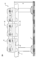
- a floor 14 is formed on the upper surface of the underframe 20.
- On the floor 14, a storage room 100 for storing an evacuation device 200 (to be described later), a chair 39, and a side sliding door that opens and closes an entrance for passengers to get on and off. 34, etc. are provided.
- FIG. 3 is a BB cross-sectional view of the monorail vehicle shown in FIG. Only one width direction 270 side where the evacuation device 200 is disposed from the center line 16 along the longitudinal direction of the monorail vehicle body 10 is shown.
- the side structure 30 constituting the monorail vehicle 10 is provided with door pockets 32 and 32 for storing side sliding doors 34 and 34 that are opened and closed when passengers get on and off, and corresponds to the lower end portion of the side sliding door 34.
- a step 24 is provided on the side surface of the underside of the underframe 20 along the opening and closing direction.
- a storage room 100 in which the evacuation device 200 is stored is provided on the side of the one side sliding door 34.
- the storage chamber 100 has a rectangular parallelepiped box shape, and includes a door 120 having a substantially L-shaped cross section in the vertical direction. The door 120 is rotated around the rotation shaft 110 provided at one vertical edge of the door 120, and the evacuation device 200 is taken in and out of the storage chamber 100.
- the other vertical edge of the door 120 is closed by a seal or the like that can be easily broken. In an emergency, after the seal is broken, the door 120 can be opened and the evacuation device 200 can be quickly taken out from the storage chamber 100. In addition, the generation of noise from the door 120 due to vibration during traveling of the monorail vehicle 10 is suppressed.
- a handrail 38 is provided on the side of the other side sliding door 34, and a chair 39 is provided on the floor 14 along the longitudinal direction of the monorail vehicle 10.
- FIG. 4 is a perspective view of the evacuation device according to the present invention as seen from the inside of the monorail vehicle to the outside of the vehicle.
- FIG. 5 is a perspective view of the evacuation device according to the present invention as seen from the outside of the monorail vehicle to the inside of the vehicle.
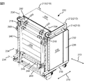
- the evacuation device 200 is a rectangular parallelepiped main body frame 210 composed of vertical members 212 and cross members 214, and both ends of the main body frame 210 in the longitudinal direction (vehicle body longitudinal direction indicated by an arrow 272).
- a holding frame 240 (see FIG. 5) having fall prevention plates 230, 230 provided along the edge and an escape shooter 260 having a spiral slide on which passengers slide down, and a tread 242 (see FIG. 7) forming an escape route.
- Reference a tread 222 (see FIG. 6) provided on the lower surface of the main body frame 210, and a shield 280 provided on the upper portion of the main body frame 210.
- the shield 280 closes the space from the upper end of the evacuation device 200 to the upper part of the entrance when the evacuation device 200 is fixed to the entrance / exit of the monorail vehicle 10 (open side sliding door 34). It is provided in the upper part of the main body frame 210 in the state where it was attached.
- the main body frame 210 has a rectangular parallelepiped shape in which a frame in which a vertical member 212 and a horizontal member 214 are combined and a frame are arranged to face each other and the frame and the frame are connected by the horizontal member 214.
- a folded escape shooter 260 is housed inside the main body frame 210.
- the fall prevention plates 230 and 230 are attached such that one of the vertical edges of the fall prevention plates 230 and 230 is rotatable around a rotation shaft 234 along the vertical member 212 forming the frame, and the evacuation device 200 is provided on the other vertical edge.
- abutting portion 236 that abuts on the door pocket pillar 36 when being provided on the door 34, and an engaging portion 232 that engages the evacuation device 200 on the door pocket pillar 36 in a manner connected to the abutting portion 236.
- a rubber plate is affixed to the abutting portion 236 for cushioning when the evacuation device 200 abuts against the door pocket pillar 36.
- the locking portion 232 has a function of suppressing movement of the evacuation device 200 in the direction of the arrow 272 (longitudinal direction of the monorail vehicle).
- the contact portion 236 does not necessarily have to be in contact with the door pocket column 36, and the vehicle width direction 270 of the evacuation device 200 is not necessarily required. What is necessary is just to contact
- the holding frame 240 that holds the escape shooter 260 is rotatably provided around a rotation shaft 244 provided at the lower end portion of the main body frame 210, and is stored in the main body frame 210 in an upright state when stored.
- a wheel 224 is provided below the cross member 214 constituting the lower surface of the main body frame 210, and the evacuation device 200 taken out from the storage 100 can be easily transported to an arbitrary side sliding door 34. Since the wheel 224 is fixed to the cross member 214 via a joint rotatable in a horizontal plane, the moving direction can be easily changed.
- FIG. 6 is a diagram showing a use situation of the evacuation device according to the present invention, and is a perspective view of the evacuation device in the use situation as seen from the inside of the monorail vehicle to the outside of the vehicle.
- illustration of the monorail vehicle 10 is abbreviate
- the evacuation device 200 taken out of the storage room 100 is transported to the vicinity of the side sliding doors 34 and 34 corresponding to the point where it is confirmed that the evacuation can be safely performed, and the side sliding doors 34 and 34 are manually opened, and then described later. Through this procedure, the door is fixed to the inside of the entrance / exit (open side doors 34, 34).
- the surfaces of the fall prevention plates 230 and 230 provided at both ends of the evacuation device 200 are deployed until they are substantially parallel to the side structure 30 (not shown) of the monorail vehicle 10.
- the fall prevention stoppers 231 and 231 provided therein are developed until they are substantially horizontal, and the deployment state of the fall prevention plates 230 and 230 is reached. Hold.
- the drop-preventing stopper 231 has a substantially right-angled triangle shape when viewed from above, and a member corresponding to one side forming a right angle of the right-angle triangle extends along the longitudinal direction of the cross member 214 forming the main body frame 210.
- the main body frame 210 is rotatably provided.
- the fall prevention stopper 231 provided so as to be rotatable is developed to a substantially horizontal height, and the inside surface of the fall prevention plate 230 is supported to support the fall prevention plate 230.
- the expanded state of is maintained.
- the holding frame 240 including the escape shooter 260 and the tread plate 242 is deployed to the outside of the vehicle, and the escape shooter 260 that has been folded and stored is deployed to the ground 1.
- the holding frame 240 has wire anchoring portions 248 and 248 (see FIG. 7) provided at the front end portion thereof and a wire anchoring portion provided at an upper portion of the main body frame 210 so that the deployed holding frame 240 can be maintained substantially horizontal. 218 and 218 are connected by wires 250 and 250.
- the shielding object 280 provided in a state of being folded on the upper part of the main body frame 210 is developed, and the upper fixing portions 284 and 284 of the shielding object 280 are provided on the upper part of the entrance / exit, and the locking part 286 (FIG. 9) and the operation of fixing the evacuation device 200 to a predetermined entrance is completed. Since the lower fixing part 282 (see FIG. 9) of the shield 280 is connected to the upper end of the main body frame 210, the shield 280 can shield the space from the upper part of the evacuation device 200 to the upper part of the entrance / exit. it can.
- the material of the shield 280 may be a window or a sheet partially provided with a transparent material, a net, a sheet folded in a bellows shape, etc. so that the evacuation guide can visually check the status of the refugee. good. Further, the shield 280 has such a strength that it will not break even when an evacuee leans on it.
- the fall prevention plates 230, 230 prevent the passenger from falling by closing the gap between the side sliding door 34 of the monorail vehicle 10 and the evacuation device 200, and the tread 222 provided at the lower part of the main body frame 210, and the deployed holding frame
- the tread 242 provided in 240 constitutes a continuous evacuation path that reaches the entrance of the escape shooter 260.
- the evacuees can easily reach the entrance of the extended escape shooter 260 from the inside of the monorail vehicle 10 via the treads 222 and 242, and thus can evacuate smoothly. Furthermore, since the shield 280 closes the open space between the upper part of the evacuation device 200 and the upper part of the entrance / exit, the safety of the evacuation guide and the refugee can be further improved. Furthermore, since the evacuation guide can see the state of the refugee through the shield 280 having the permeable part, the evacuation situation can be easily grasped. Therefore, since it is possible to suppress the escape shooter 260 from guiding more evacuees than the capacity at one time, safety can be improved.
- the fall prevention plate 230 may be formed of an extruded shape that is extruded along the vertical direction, or a structure in which a thin plate is attached as a skin member to a frame that is a bone member in order to reduce weight. There may be.
- the shielding object 280 does not necessarily need to be equipped with the evacuation apparatus 200, and it is separate from the evacuation apparatus 200 to the storage chamber 100.
- the space from the upper part of the evacuation device 200 to the upper part of the entrance / exit may be closed with a separate shield 280, or
- the shield 280 is provided in a folded state at the upper part (the upper part inside the vehicle of the side structure 30), and after the evacuation device 200 is fixed to the entrance / exit, the shield 280 is extended from the upper part of the entrance / exit.
- the space from the upper part of the entrance / exit to the upper part of the evacuation device 200 may be closed by connecting to the upper part of 200.
- FIG. 7 is a perspective view illustrating a developed state of the holding frame including the tread included in the evacuation device illustrated in FIG. 6.
- the holding frame 240 is formed of a rectangular frame, and a cylinder 243 on one side forming the frame is provided to be rotatable around a rotation shaft 234 at the bottom of the main body frame 210.
- Another cylindrical body 244 is provided on the holding frame 240 in a form along the axis of the cylindrical body 243 forming the holding frame 240.
- the cylindrical body 244 is provided with an abutting portion 246 that abuts on a step 24 (see FIG. 3) provided at a lower portion of the entrance when the holding frame 210 is expanded to the outside of the vehicle at the time of evacuation.
- the abutting portion 246 is a member made of a plate material, and has an L-shaped vertical cross-sectional shape so that it can abut on the step 24 on two sides.
- a tread 242 is provided in such a manner as to straddle the cylindrical body 243 and the cylindrical body 244, and constitutes a part of the route where the evacuees reach the entrance of the escape shooter 260.
- a canvas holding frame 292 that supports a canvas (not shown) that covers a range from the tread 242 provided in the holding frame 240 to the entrance of the escape shooter 260 from the inside, and serves as a handrail when the passenger slides into the entrance of the escape shooter 260. Is provided in such a manner that it can be rotated around the rotation axis 234 of the cylindrical body 243.
- the campus holding frame 292 includes a mechanism (not shown) that can maintain the angle ⁇ with respect to the holding frame 240.
- the cylinder 245 which is one side of the holding frame 240 and is most distant from the cylinder 243 that is rotatably connected to the main body frame 210 is tethered to the belts 250 and 250 supporting the canvas described above. Portions 249 and 249 are provided.
- FIG. 8 is a top view (corresponding to FIG. 3) showing a state where the evacuation device according to the present invention is fixed to the side sliding door of the monorail vehicle.
- the evacuation device 200 is pulled out from the hangar 100 to the vicinity of the selected side sliding doors 34 and 34.
- the side sliding doors 34, 34 are opened by handling a door cock or the like that can be manually opened and closed.
- the contact portions 236, 236 of the fall prevention plates 230, 230 are moved to the door pocket. It is made to contact
- the locking portions 232 and 232 continuously provided in the contact portions 236 and 236 lock the door column pillars 36 and 36 to suppress the movement of the evacuation device 200 in the longitudinal direction of the monorail vehicle 10.
- the abutting portion 236 can increase the shock when the fall prevention plate 230 is brought into contact with the door column 36 and the frictional force in the longitudinal direction of the monorail vehicle 10 between the fall prevention plate 230 and the surface of the door column 36. Rubber etc. are provided.
- the fall prevention plate 230 has a safety function for preventing the passenger from escaping from the gap between the evacuation device 200 and the opened side sliding door 36 and a function for fixing the evacuation device 200 to the monorail vehicle 10 when the passenger evacuates. Have both. Since the dimension along the monorail vehicle body 10 when the fall prevention plates 230, 230 of the evacuation device 200 are deployed is set slightly larger than the dimension of the opened side sliding doors 34, 34, the evacuation device 200 is separated from the monorail vehicle 10 on the ground. Can be prevented from falling to.
- the tread 242 is provided in such a manner that it projects outward from the side structure 30 in the width direction (direction of arrow 270) of the monorail vehicle 10, and the escape shooter 260 is located outside the tread 242 (in the direction away from the monorail vehicle 10).
- the escape shooter 260 deployed from the holding frame 240 toward the ground 1 is installed at a position away from the skirt 22 of the monorail vehicle 10, and the escape shooter 260 may contact the monorail vehicle 10. Since it is suppressed, the safety of evacuees can be increased.
- FIG. 9 is a cross-sectional view taken along the line CC when the evacuation device shown in FIG. 8 is fixed to a monorail vehicle.
- the holding frame 240 provided in the evacuation device 200 is expanded in the direction of pushing from the vehicle inner side to the vehicle outer side, the mooring portions 218 and 218 provided at the upper end portion of the main body frame 210 and the wire mooring portion 248 provided in the holding frame 240. 248 is connected by the wires 250 and 250, so that the holding frame 240 including the tread 242 is maintained substantially horizontal.
- the escape shooter 260 folded and stored in the main body frame 210 is extended in the process of descending, and an evacuation path from the tread board 222 through the tread board 242 to the escape shooter 260 is formed.
- the shielding object 280 provided in a state of being folded on the upper part of the main body frame 210 of the evacuation device 200 is developed, and the upper fixing portions 284 and 284 of the shielding object 280 are provided at the upper part of the entrance / exit. As a result, the operation of fixing the series of evacuation devices 200 to a predetermined entrance / exit is completed.
- the evacuation device 200 Since the lower fixing portion 282 (see FIG. 9) of the shield 280 is connected to the upper end portion of the main body frame 210, the evacuation device 200 is provided by the shield 280 made of a sheet or a net having a partially transparent portion. The space from the top of the door to the top of the entrance is blocked. In other words, since the height dimension h1 of the evacuation device 200 is smaller than the height dimension h2 of the entrance / exit, the open range from the upper part of the evacuation apparatus 200 to the upper part of the entrance / exit is covered with the shield 280 and closed. Yes.
- the belt anchoring portions 249 and 249 at the upper end portion of the main body frame 210 and the belt anchoring portions 249 and 249 provided in the cylindrical body 245 forming the holding frame 240 are connected by belts 254 and 254 via the canvas support frame 292.
- the belts 254 and 254 and the canvas support frame 292 support a canvas (not shown) that covers the escape path from the tread 242 to the entrance of the escape shooter 260 from the inside.
- the canvas prevents the evacuees from recognizing the height, they can reduce the fear of the evacuees and promote prompt evacuation. Further, since the holding frame 240 is maintained substantially horizontal, the evacuees go through the tread board 222 provided at the lower part of the main body frame 210 continuously arranged from the floor 14 and the tread board 242 provided in the holding frame 240. Since the evacuation route to the entrance of the escape shooter 260 can be easily advanced, the evacuation can be promptly performed. Moreover, since the shield 280 blocks the open space between the upper part of the evacuation device 200 and the upper part of the entrance / exit, the safety of the evacuation guide and the refugee can be further improved. Furthermore, since the shield 280 has a part where the state of the refugee can be seen, the evacuation guider can easily grasp the evacuation situation and can suppress guiding more refugees than the capacity of the escape shooter 260 at one time. .
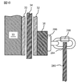
- FIG. 10 is an enlarged cross-sectional view of EE for showing the fixing position of the evacuation device shown in FIG. 9, and shows the connection structure between the upper part of the entrance / exit of the monorail vehicle 10 and the upper fixing part 284 of the shield 280.
- a mooring portion 286 having a ring-shaped portion is provided on the upper portion of the door column pillar 36 in the vicinity of the entrance / exit, and the mooring portion 286 and the upper fixing portion 284 of the shield 280 are connected by a fastener 288.
- the mooring portion 286 may be provided not in the side structure 30 but in the interior material or the door pocket 32 or the door pocket pillar 36 provided in the side structure 30 and having an appropriate strength.
- FIG. 11 is a view of the evacuation device fixed to the monorail vehicle as viewed from the inside of the vehicle.
- a state in which the range from the upper part of the evacuation device 200 that is fixed to the entrance / exit by unfolding the fall prevention plates 230, 230 to the upper part of the entrance / exit that opens the side sliding doors 34, 34 is covered by the shielding object 280. Is shown.
- the safety of the evacuation guide and the refugee can be further increased.
- the evacuation guide can visually check the state of the refugee through the shield 280, the evacuation state can be easily grasped, and it is possible to suppress guiding more refugees than the capacity of the escape shooter 260 at one time.
Abstract
The invention is an evacuation device provided on a rail vehicle operated along an elevated railway. Using the evacuation device, which has been installed with a side sliding door of the rail vehicle open, the safety of an evacuating evacuee and of an evacuation guidance provider who guides the evacuee is increased. A screen (280) provided in a folded state at an upper portion of a body frame (210) is opened, and locks an upper fixed portion (284) of the screen (280) with a lock section (286) provided at an upper portion of an entrance/exit. Since a lower-portion fixed portion (282) of the screen (280) is connected to an upper end portion of the body frame (210), the screen (280) is capable of screening a space extending from an upper portion of the evacuation device (200) to the upper portion of the entrance/exit. So as to enable the evacuation guidance provider to visually inspect the condition of the evacuee, the screen (280) material may be a sheet or a net, said sheet being partially provided with a window or a permeable material.
Description
本発明は、特に、高架に設置された軌道に沿って走行する軌条車両に備えられる避難装置、当該避難装置を備える軌条車両に係るものであり、特に、避難装置の近傍で避難者を誘導する避難誘導員および避難者の避難時の安全性を高めることができる避難装置、当該避難装置を備える軌条車両、および避難装置の軌条車両への固定方法に関する。
In particular, the present invention relates to an evacuation device provided in a rail vehicle that travels along a track installed on an overpass, and a rail vehicle including the evacuation device, and particularly guides an evacuee near the evacuation device. The present invention relates to an evacuation device capable of enhancing safety during evacuation of an evacuation guide and an evacuee, a rail vehicle provided with the evacuation device, and a method of fixing the evacuation device to the rail vehicle.
高架に敷設される軌条に沿って走行する軌条車両に、重大な故障あるいは火災等が生じた場合、乗客を当該車両から避難させる必要が生じる。当該車両が駅に停車中であれば、駅に併設される乗降用ホームへ避難することができる。しかしながら、高架に敷設された軌条を走行中の軌条車両であって、ホームなど避難に供することができる構造物が無い駅と駅との間を走行中に前述した事象が生じた場合、その場に停車した当該車両から乗客を安全に避難誘導しなければならない。
隣接する複線の高架軌道を走行する場合であれば、対向する高架軌道に、当該編成車両に対して並列に救援編成車両を停車させ、当該編成車両と救援編成車両の対面する側引戸を開放した後、避難用通路(梯子)を両車両の側引戸の間に架設して、当該編成車両から救援編成車両へ乗客を避難誘導する方法が検討されている。また、単線の高架上であれば、当該編成車両に直列に救援編成車両を停車させて、当該編成車両の後尾車両から救援編成車両の先頭車両へ避難用通路(梯子)を架設して、乗客を避難誘導する方法が検討されている。 When a serious failure or a fire occurs in a rail vehicle that runs along a rail laid on an overpass, it is necessary to evacuate passengers from the vehicle. If the vehicle is stopped at the station, it is possible to evacuate to a boarding / alighting platform attached to the station. However, if the above-mentioned event occurs while traveling between a station and a railway vehicle that is traveling on a rail laid on an overpass and does not have a structure that can be used for evacuation, such as a platform, Passengers must be safely evacuated from the vehicle stopped at
When traveling on an adjacent double track elevated track, the rescue formation vehicle is stopped in parallel with the formation vehicle on the opposite elevation track, and the side sliding doors facing the formation vehicle and the relief formation vehicle are opened. Thereafter, a method of evacuating passengers from the trained vehicle to the rescue train by constructing an evacuation passage (ladder) between the side sliding doors of both vehicles is being studied. In addition, if it is on a single line elevated, the rescue formation vehicle is stopped in series with the formation vehicle, and an evacuation passage (ladder) is constructed from the rear vehicle of the formation vehicle to the leading vehicle of the relief formation vehicle, A method to guide evacuation is being studied.
大規模地震等で軌条車両の運行に必要な電力を供給する変電施設に重大な支障が生じた場合など、高架を走行する複数の軌条車両が停車するため、救援編成車両を運行することが難しいと推察されている。このため救援編成車両に依存することなく当該編成車両に備えられる避難装置によって、当該編成車両から乗客が安全に地上へ避難できる避難装置が考案されている。
この避難装置は、軌条車両の車内に設置されており、軌条車両の任意の側引戸に選択的に設置することができるとともに、軌条車両の側引戸に簡便な構成と手順で固定できる特長を有している。この避難装置の構成は特許文献1に示されている。 It is difficult to operate rescue trains because multiple rail vehicles that run overpass stop when there is a serious hindrance in a substation facility that supplies power necessary for the operation of rail vehicles due to a large-scale earthquake, etc. It is guessed. For this reason, an evacuation device has been devised that allows passengers to evacuate safely from the trained vehicle to the ground by using the evacuation device provided in the trained vehicle without depending on the rescue train.
This evacuation device is installed inside the rail vehicle, and can be selectively installed on any side sliding door of the rail vehicle, and can be fixed to the side sliding door of the rail vehicle with a simple configuration and procedure. is doing. The configuration of this evacuation device is shown in Patent Document 1.
軌条車両から地上へ避難する場合、まず、軌条車両に添乗する乗務員等(以下、避難誘導者)がこの避難装置を保管場所から引き出して、側引戸を開放した乗降口に設置する。その後、避難誘導者が乗客を避難装置へ誘導して、避難装置に内蔵される脱出シュータを用いて地上へ避難させる。
避難誘導者は、開放された側引戸に設置された避難装置付近で避難者を避難装置(脱出シュータ:筒体の内部に螺旋状の滑り台が備えられたもの)の入口へ誘導するとともに、脱出シュータで降下する避難者の数が脱出シュータの定員を超過しないように監視しなければならない。このため、脱出シュータの出口から地上へ避難する避難者の様子を、軌条車両から目視できることが望ましく、避難者や避難誘導者の安全をより高める点において改善すべき課題がある。 When evacuating from the rail vehicle to the ground, first, a crew member or the like (hereinafter referred to as an evacuation guide) who rides on the rail vehicle pulls out the evacuation device from the storage location and installs it at the entrance / exit where the side sliding door is opened. Thereafter, the evacuation guide guides the passenger to the evacuation device and evacuates to the ground using the escape shooter built in the evacuation device.
The evacuation guide guides the refugee to the entrance of the evacuation device (an escape shooter with a spiral slide inside the cylinder) near the evacuation device installed in the opened side sliding door and escapes. It must be monitored that the number of evacuees descending on the shooter does not exceed the escape shooter capacity. For this reason, it is desirable that the state of the refugee evacuating from the exit of the escape shooter to be seen from the rail vehicle, and there is a problem to be improved in terms of further improving the safety of the refugee and the evacuation guide.
本発明の目的は、高架に敷設された軌条に沿って運行される軌条車両に備えられる避難装置であって、避難装置を側引き戸に選択的に設置することができるとともに、軌条車両の側引戸に簡便な構成と手順で避難装置を固定でき、避難者及び避難誘導者がより安全に使用できる避難装置を提供することにある。
An object of the present invention is an evacuation device provided in a rail vehicle that is operated along a rail laid on an overpass, and the evacuation device can be selectively installed on a side sliding door, and the side sliding door of the rail vehicle It is another object of the present invention to provide an evacuation device that can be fixed with a simple configuration and procedure and that can be used more safely by refugees and evacuation guides.
本発明の目的を達成するため、本発明による軌条車両は、乗降口に設置される避難装置を備えており、この避難装置は脱出経路をなす脱出シュータと、この避難装置の上部から前記乗降口の上部に至る範囲を覆う遮蔽物とを有することを特徴とする。
In order to achieve the object of the present invention, a rail vehicle according to the present invention includes an evacuation device installed at an entrance / exit, and the evacuation device is an escape shooter that forms an escape route, and the entrance / exit from above the evacuation device. It has the shielding object which covers the range which reaches the upper part of this.
また、本発明による避難装置は、軌条車両の乗降口に備えられるとともに、本体フレームの左右両枠部に配設される鉛直軸の周りに回動可能に備えられる落下防止板と、この本体フレームの下端部に配設される水平軸の周りに回動可能に備えられる保持フレームと、この保持フレームに備えられる脱出シュータとを備えており、さらに、当該避難装置の上部から乗降口の上部に至る範囲を覆う遮蔽物を備えることを特徴とする。
The evacuation device according to the present invention is provided at the entrance / exit of the rail vehicle, and is provided with a fall prevention plate provided so as to be rotatable around the vertical shafts disposed on the left and right frame portions of the main body frame, and the main body frame. A holding frame rotatably provided around a horizontal axis disposed at a lower end of the evacuation unit, and an escape shooter provided in the holding frame, and further from the upper part of the evacuation device to the upper part of the entrance / exit It is characterized by including a shield covering the entire range.
本発明によれば、避難装置を側引き戸に選択的に設置することができるとともに、軌条車両の側引戸に簡便な構成と手順で避難装置を固定でき、さらに、避難者及び避難誘導者の安全をより高めることができる避難装置を提供することができる。
According to the present invention, the evacuation device can be selectively installed on the side sliding door, and the evacuation device can be fixed to the side sliding door of the rail vehicle with a simple configuration and procedure. Can be provided.
以下、図面を参照して本発明による避難装置の一実施例を説明する。
図1は、軌条車両の一例として挙げる跨座型モノレール車両10(以下、「モノレール車両10」という)の側面図である。軌条車両とは、敷設された軌道に案内されて走行する車両であり、鉄道車両、跨座型(懸垂型)モノレール車両、新交通システム用車両等である。本発明では、軌条車両の例として跨座型モノレール車両を例に挙げて、高架に敷設された軌条(軌道)に沿って運行されるとともに乗降口に備えられる避難装置を備える跨座型モノレール車両10と、この跨座型モノレール車両10に備えられる避難装置200と、この避難装置200を跨座型モノレール車両10の乗降口に固定する方法について説明する。 Hereinafter, an embodiment of an evacuation device according to the present invention will be described with reference to the drawings.
FIG. 1 is a side view of a straddle-type monorail vehicle 10 (hereinafter referred to as “monorail vehicle 10”) as an example of a rail vehicle. A rail vehicle is a vehicle that travels while being guided by a laid track, such as a railway vehicle, a straddle type (suspension type) monorail vehicle, a vehicle for a new transportation system, and the like. In the present invention, a straddle-type monorail vehicle is provided as an example of a rail vehicle, and is operated along a rail (track) laid on an overpass and provided with an evacuation device provided at an entrance / exit. 10, the evacuation device 200 provided in the straddle-type monorail vehicle 10 and a method of fixing the evacuation device 200 to the entrance / exit of the straddle-type monorail vehicle 10 will be described.
図1は、軌条車両の一例として挙げる跨座型モノレール車両10(以下、「モノレール車両10」という)の側面図である。軌条車両とは、敷設された軌道に案内されて走行する車両であり、鉄道車両、跨座型(懸垂型)モノレール車両、新交通システム用車両等である。本発明では、軌条車両の例として跨座型モノレール車両を例に挙げて、高架に敷設された軌条(軌道)に沿って運行されるとともに乗降口に備えられる避難装置を備える跨座型モノレール車両10と、この跨座型モノレール車両10に備えられる避難装置200と、この避難装置200を跨座型モノレール車両10の乗降口に固定する方法について説明する。 Hereinafter, an embodiment of an evacuation device according to the present invention will be described with reference to the drawings.
FIG. 1 is a side view of a straddle-type monorail vehicle 10 (hereinafter referred to as “
図1に示すモノレール車両10は3両の車両が連結されて編成を構成しており、地面1から高さHの高架に敷設された軌道桁2の上を走行する。モノレール車両10は、軌道桁2の上面を転動する支持輪と、軌道桁の両側面を転動する案内輪及び安定輪とを備える台車(図示なし)に支持されて軌道桁2に沿って走行する。
モノレール車両10の屋根上には空調装置45が備えられ、車内の温湿度を調整する。モノレール車両10を支持する台車と、モノレール車両10の床下に備えられる各種機器は、後述する側構体30に連続する形態で備えられるスカート22によって覆われており、これら機器から生じる騒音の伝播を抑制している。 Amonorail vehicle 10 shown in FIG. 1 is composed of three vehicles connected to each other, and travels on a track girder 2 that is laid from the ground 1 to a height H. The monorail vehicle 10 is supported along a track girder 2 by being supported by a carriage (not shown) including a support wheel that rolls on the upper surface of the track girder 2 and guide wheels and stabilizer wheels that roll on both side surfaces of the track girder. Run.
Anair conditioner 45 is provided on the roof of the monorail vehicle 10 to adjust the temperature and humidity in the vehicle. The bogie that supports the monorail vehicle 10 and various devices provided under the floor of the monorail vehicle 10 are covered with a skirt 22 that is provided in a form continuous with the side structure 30 described later, and suppresses the propagation of noise generated from these devices. is doing.
モノレール車両10の屋根上には空調装置45が備えられ、車内の温湿度を調整する。モノレール車両10を支持する台車と、モノレール車両10の床下に備えられる各種機器は、後述する側構体30に連続する形態で備えられるスカート22によって覆われており、これら機器から生じる騒音の伝播を抑制している。 A
An
図2は、図1に示すモノレール車両10のA-A断面図である。モノレール車両10は、台枠20の幅方向の両端部に側構体30,30を備えるとともに、長手方向の両端部に妻構体(図示なし)を備え、側構体30,30及び妻構体の上端部に屋根構体40を載置することによって構成される。
台枠20の下面には、主変換機、変圧器、補助電源装置等の床下機器(図示なし)が搭載される床下機器室が備えられる。台枠20の上面には床14が構成されており、床14の上には後述する避難装置200を格納する格納室100、椅子39、乗客の乗降に供される乗降口を開閉する側引戸34等の艤装品が備えられる。 FIG. 2 is a cross-sectional view of themonorail vehicle 10 shown in FIG. The monorail vehicle 10 includes side structures 30 and 30 at both ends in the width direction of the underframe 20, and includes wife structures (not shown) at both ends in the longitudinal direction, and the upper ends of the side structures 30 and 30 and the wife structure. It is comprised by mounting the roof structure 40 in the.
The underside of theunderframe 20 is provided with an underfloor equipment room in which underfloor equipment (not shown) such as a main converter, a transformer, and an auxiliary power supply is mounted. A floor 14 is formed on the upper surface of the underframe 20. On the floor 14, a storage room 100 for storing an evacuation device 200 (to be described later), a chair 39, and a side sliding door that opens and closes an entrance for passengers to get on and off. 34, etc. are provided.
台枠20の下面には、主変換機、変圧器、補助電源装置等の床下機器(図示なし)が搭載される床下機器室が備えられる。台枠20の上面には床14が構成されており、床14の上には後述する避難装置200を格納する格納室100、椅子39、乗客の乗降に供される乗降口を開閉する側引戸34等の艤装品が備えられる。 FIG. 2 is a cross-sectional view of the
The underside of the
図3は、図2に示すモノレール車両のB-B断面図である。モノレール車体10の長手方向に沿う中心線16から避難装置200が配置されている一方の幅方向270の側のみを示す。モノレール車両10を構成する側構体30には、乗客等が乗降する際に開閉される側引戸34,34が収納される戸袋32,32が設けられており、側引戸34の下端部に対応する台枠20の車外側の側面には、その開閉方向に沿ってステップ24が備えられる。
図3に示す側引戸34,34は対向する2枚の引戸の各々がモノレール車両10の長手方向に沿って開閉する両開きタイプであるが、1枚の引戸からなる片開きタイプの側引戸であってもよい。戸袋32,32の側引戸34,34の側の端部の車内側の面には、鉛直方向に沿って戸袋柱36,36が備えられる。図示はしないが、戸袋柱36の車内側の面に手摺が備えられることもある。
一方の側引戸34の側に、避難装置200が格納される格納室100が備えられる。格納室100は直方体の箱状であり、鉛直方向の断面形状が略L字形の扉120を備えている。この扉120の一方の鉛直縁部に備えられる回転軸110周りに、扉120を回転させて、避難装置200を格納室100へ出し入れする。 3 is a BB cross-sectional view of the monorail vehicle shown in FIG. Only onewidth direction 270 side where the evacuation device 200 is disposed from the center line 16 along the longitudinal direction of the monorail vehicle body 10 is shown. The side structure 30 constituting the monorail vehicle 10 is provided with door pockets 32 and 32 for storing side sliding doors 34 and 34 that are opened and closed when passengers get on and off, and corresponds to the lower end portion of the side sliding door 34. A step 24 is provided on the side surface of the underside of the underframe 20 along the opening and closing direction.
The side sliding doors 34 and 34 shown in FIG. 3 are double-opening type in which each of the two opposing sliding doors opens and closes along the longitudinal direction of the monorail vehicle 10, but is a single-opening type side sliding door consisting of a single sliding door. May be. Door interior pillars 36 and 36 are provided along the vertical direction on the surface on the vehicle interior side of the side sliding doors 34 and 34 side of the door pockets 32 and 32. Although not shown, a handrail may be provided on the inner surface of the door pocket pillar 36.
Astorage room 100 in which the evacuation device 200 is stored is provided on the side of the one side sliding door 34. The storage chamber 100 has a rectangular parallelepiped box shape, and includes a door 120 having a substantially L-shaped cross section in the vertical direction. The door 120 is rotated around the rotation shaft 110 provided at one vertical edge of the door 120, and the evacuation device 200 is taken in and out of the storage chamber 100.
図3に示す側引戸34,34は対向する2枚の引戸の各々がモノレール車両10の長手方向に沿って開閉する両開きタイプであるが、1枚の引戸からなる片開きタイプの側引戸であってもよい。戸袋32,32の側引戸34,34の側の端部の車内側の面には、鉛直方向に沿って戸袋柱36,36が備えられる。図示はしないが、戸袋柱36の車内側の面に手摺が備えられることもある。
一方の側引戸34の側に、避難装置200が格納される格納室100が備えられる。格納室100は直方体の箱状であり、鉛直方向の断面形状が略L字形の扉120を備えている。この扉120の一方の鉛直縁部に備えられる回転軸110周りに、扉120を回転させて、避難装置200を格納室100へ出し入れする。 3 is a BB cross-sectional view of the monorail vehicle shown in FIG. Only one
The
A
扉120の他方の鉛直縁部は、容易に破断できるシール等によって閉じられており、非常時にはシールを破断した後、扉120を開いて格納室100から避難装置200を速やかに取り出すことができるとともに、モノレール車両10の走行時の振動に起因する騒音が扉120から発生することを抑制している。他方の側引戸34の側には手摺38が備えられるとともに、モノレール車両10の長手方向に沿って床14の上に椅子39が備えられる。
The other vertical edge of the door 120 is closed by a seal or the like that can be easily broken. In an emergency, after the seal is broken, the door 120 can be opened and the evacuation device 200 can be quickly taken out from the storage chamber 100. In addition, the generation of noise from the door 120 due to vibration during traveling of the monorail vehicle 10 is suppressed. A handrail 38 is provided on the side of the other side sliding door 34, and a chair 39 is provided on the floor 14 along the longitudinal direction of the monorail vehicle 10.
図4は、本発明による避難装置をモノレール車両の車内側から車外側に見た斜視図である。図5は、本発明による避難装置をモノレール車両の車外側から車内側に見た斜視図である。
FIG. 4 is a perspective view of the evacuation device according to the present invention as seen from the inside of the monorail vehicle to the outside of the vehicle. FIG. 5 is a perspective view of the evacuation device according to the present invention as seen from the outside of the monorail vehicle to the inside of the vehicle.
避難装置200は、縦材212と横材214ととから構成される直方体状の本体フレーム210と、本体フレーム210の長手方向(矢印272で示す車体長手方向)の両端部であって、その垂直縁に沿って備えられる落下防止板230,230と、乗客が滑り降りる螺旋状滑り台を内部に有する脱出シュータ260を保持するとともに避難路を成す踏板242(図7参照)を備える保持フレーム240(図5参照)と、本体フレーム210の下面に備えられる踏板222(図6参照)と、本体フレーム210の上部に備えられる遮蔽物280と、を有する。
The evacuation device 200 is a rectangular parallelepiped main body frame 210 composed of vertical members 212 and cross members 214, and both ends of the main body frame 210 in the longitudinal direction (vehicle body longitudinal direction indicated by an arrow 272). A holding frame 240 (see FIG. 5) having fall prevention plates 230, 230 provided along the edge and an escape shooter 260 having a spiral slide on which passengers slide down, and a tread 242 (see FIG. 7) forming an escape route. Reference), a tread 222 (see FIG. 6) provided on the lower surface of the main body frame 210, and a shield 280 provided on the upper portion of the main body frame 210.
遮蔽物280は、モノレール車両10の乗降口(開放された側引戸34)に避難装置200を固定した時に、避難装置200の上端部から乗降口の上部に至る空間を閉鎖するものであり、折りたたまれた状態で本体フレーム210の上部に備えられている。
The shield 280 closes the space from the upper end of the evacuation device 200 to the upper part of the entrance when the evacuation device 200 is fixed to the entrance / exit of the monorail vehicle 10 (open side sliding door 34). It is provided in the upper part of the main body frame 210 in the state where it was attached.
本体フレーム210は、縦材212と横材214とを組み合わせた枠と枠とを対向して配置して、枠と枠とを横材214で連結した直方体状である。本体フレーム210の内部には折り畳まれた状態の脱出シュータ260が収納されている。
落下防止板230、230は、その一方の垂直縁を、枠をなす縦材212に沿う回転軸234周りに回動可能に取り付けられるとともに、その他方の垂直縁には、避難装置200が側引戸34に備えられる時に戸袋柱36に当接される当接部236と、当接部236に接続する態様で戸袋柱36に避難装置200を係止する係止部232を備える。 Themain body frame 210 has a rectangular parallelepiped shape in which a frame in which a vertical member 212 and a horizontal member 214 are combined and a frame are arranged to face each other and the frame and the frame are connected by the horizontal member 214. A folded escape shooter 260 is housed inside the main body frame 210.
The fall prevention plates 230 and 230 are attached such that one of the vertical edges of the fall prevention plates 230 and 230 is rotatable around a rotation shaft 234 along the vertical member 212 forming the frame, and the evacuation device 200 is provided on the other vertical edge. 34 is provided with an abutting portion 236 that abuts on the door pocket pillar 36 when being provided on the door 34, and an engaging portion 232 that engages the evacuation device 200 on the door pocket pillar 36 in a manner connected to the abutting portion 236.
落下防止板230、230は、その一方の垂直縁を、枠をなす縦材212に沿う回転軸234周りに回動可能に取り付けられるとともに、その他方の垂直縁には、避難装置200が側引戸34に備えられる時に戸袋柱36に当接される当接部236と、当接部236に接続する態様で戸袋柱36に避難装置200を係止する係止部232を備える。 The
The
当接部236には、避難装置200を戸袋柱36に当接した時の緩衝のためにゴム板が貼り付けられる。係止部232は、避難装置200の矢印272の方向(モノレール車両の長手方向)の動きを抑制する機能を有す。当接部236が戸袋柱36に当接される場合を例に挙げて説明するが、当接部236は必ずしも戸袋柱36に当接される必要はなく、避難装置200の車体幅方向270の方向に固定できる部位に当接されれば良い。
A rubber plate is affixed to the abutting portion 236 for cushioning when the evacuation device 200 abuts against the door pocket pillar 36. The locking portion 232 has a function of suppressing movement of the evacuation device 200 in the direction of the arrow 272 (longitudinal direction of the monorail vehicle). Although the case where the contact portion 236 is in contact with the door pocket pillar 36 will be described as an example, the contact portion 236 does not necessarily have to be in contact with the door pocket column 36, and the vehicle width direction 270 of the evacuation device 200 is not necessarily required. What is necessary is just to contact | abut to the site | part which can be fixed to a direction.
脱出シュータ260を保持する保持フレーム240は、本体フレーム210の下端部に設けられる回転軸244周りに回動可能に備えられており、収納時には直立した態様で本体フレーム210に収容されている。本体フレーム210の下面を構成する横材214の下方には車輪224が備えられており、格納庫100から取り出された避難装置200を任意の側引戸34まで車内を容易に搬送できる。車輪224は水平面内で回転可能な継手を介して横材214に固定されているので容易に移動方向も変更できる。
The holding frame 240 that holds the escape shooter 260 is rotatably provided around a rotation shaft 244 provided at the lower end portion of the main body frame 210, and is stored in the main body frame 210 in an upright state when stored. A wheel 224 is provided below the cross member 214 constituting the lower surface of the main body frame 210, and the evacuation device 200 taken out from the storage 100 can be easily transported to an arbitrary side sliding door 34. Since the wheel 224 is fixed to the cross member 214 via a joint rotatable in a horizontal plane, the moving direction can be easily changed.
図6は、本発明による避難装置の使用状況を示す図であって、使用状況にある避難装置をモノレール車両の車内側から車外側に見た斜視図である。なお、避難装置200がモノレール車両10の乗降口(開放された側引戸34)に固定される様子を示すため、モノレール車両10の描写を省略している。
格納室100から出された避難装置200を、安全に避難できることが確認された地点に対応する側引戸34,34の近くに搬送して、当該側引戸34,34を手動で開放した後、後述する手順を経て乗降口(開放された側引戸34,34)の車内側に固定される。 FIG. 6 is a diagram showing a use situation of the evacuation device according to the present invention, and is a perspective view of the evacuation device in the use situation as seen from the inside of the monorail vehicle to the outside of the vehicle. In addition, in order to show a mode that theevacuation apparatus 200 is fixed to the entrance / exit of the monorail vehicle 10 (open side sliding door 34), illustration of the monorail vehicle 10 is abbreviate | omitted.
Theevacuation device 200 taken out of the storage room 100 is transported to the vicinity of the side sliding doors 34 and 34 corresponding to the point where it is confirmed that the evacuation can be safely performed, and the side sliding doors 34 and 34 are manually opened, and then described later. Through this procedure, the door is fixed to the inside of the entrance / exit (open side doors 34, 34).
格納室100から出された避難装置200を、安全に避難できることが確認された地点に対応する側引戸34,34の近くに搬送して、当該側引戸34,34を手動で開放した後、後述する手順を経て乗降口(開放された側引戸34,34)の車内側に固定される。 FIG. 6 is a diagram showing a use situation of the evacuation device according to the present invention, and is a perspective view of the evacuation device in the use situation as seen from the inside of the monorail vehicle to the outside of the vehicle. In addition, in order to show a mode that the
The
まず、避難装置200の両端部に備えられる落下防止板230、230の面がモノレール車両10の側構体30(図示なし)に対してほぼ平行になるまで展開する。
次に、落下防止板230、230の展開状態を保持するために、その内部に備えられている落下防止ストッパ231,231を略水平になるまで展開して、落下防止板230,230の展開状態を保持する。落下防止ストッパ231は、俯瞰した時の形状が略直角3角形状であり、直角3角形の直角をなす一方の辺に相当する部材が、本体フレーム210をなす横材214の長手方向に沿う態様で本体フレーム210の上部に回動可能に備えられている。落下防止板230を展開した後、この回動可能に備えられた落下防止ストッパ231を略水平になる高さまで展開し、落下防止板230の車内側の面を支持することによって、落下防止板230の展開状態が保持される。 First, the surfaces of the fall prevention plates 230 and 230 provided at both ends of the evacuation device 200 are deployed until they are substantially parallel to the side structure 30 (not shown) of the monorail vehicle 10.
Next, in order to maintain the deployed state of the fall prevention plates 230 and 230, the fall prevention stoppers 231 and 231 provided therein are developed until they are substantially horizontal, and the deployment state of the fall prevention plates 230 and 230 is reached. Hold. The drop-preventing stopper 231 has a substantially right-angled triangle shape when viewed from above, and a member corresponding to one side forming a right angle of the right-angle triangle extends along the longitudinal direction of the cross member 214 forming the main body frame 210. The main body frame 210 is rotatably provided. After the fall prevention plate 230 is deployed, the fall prevention stopper 231 provided so as to be rotatable is developed to a substantially horizontal height, and the inside surface of the fall prevention plate 230 is supported to support the fall prevention plate 230. The expanded state of is maintained.
次に、落下防止板230、230の展開状態を保持するために、その内部に備えられている落下防止ストッパ231,231を略水平になるまで展開して、落下防止板230,230の展開状態を保持する。落下防止ストッパ231は、俯瞰した時の形状が略直角3角形状であり、直角3角形の直角をなす一方の辺に相当する部材が、本体フレーム210をなす横材214の長手方向に沿う態様で本体フレーム210の上部に回動可能に備えられている。落下防止板230を展開した後、この回動可能に備えられた落下防止ストッパ231を略水平になる高さまで展開し、落下防止板230の車内側の面を支持することによって、落下防止板230の展開状態が保持される。 First, the surfaces of the
Next, in order to maintain the deployed state of the
次に、脱出シュータ260と踏板242とを備える保持フレーム240を、車外側に展開するとともに、折り畳まれて収納されていた脱出シュータ260を地面1に至るまで展開する。保持フレーム240は、展開された保持フレーム240が略水平を維持できるように、その先端部に備えられるワイヤ係留部248,248(図7参照)と本体フレーム210の上部に備えあれるワイヤ係留部218,218とがワイヤ250,250で繋がれている。
Next, the holding frame 240 including the escape shooter 260 and the tread plate 242 is deployed to the outside of the vehicle, and the escape shooter 260 that has been folded and stored is deployed to the ground 1. The holding frame 240 has wire anchoring portions 248 and 248 (see FIG. 7) provided at the front end portion thereof and a wire anchoring portion provided at an upper portion of the main body frame 210 so that the deployed holding frame 240 can be maintained substantially horizontal. 218 and 218 are connected by wires 250 and 250.
次に、本体フレーム210の上部に畳まれた状態で備えられている遮蔽物280を展開して、遮蔽物280の上部固定部284,284を乗降口の上部に備えられる係止部286(図9参照)に係止して避難装置200を所定の乗降口に固定する作業が完了する。遮蔽物280の下部固定部282(図9参照)は、本体フレーム210の上端部に接続されているので、遮蔽物280は避難装置200の上部から乗降口の上部に至る空間を遮蔽することができる。遮蔽物280の材質は、避難誘導者が、避難者の状況を目視できるように、窓あるいは透過性の材質を部分的に備えるシート、あるいはネット、蛇腹状に折り畳まれたシートなどであっても良い。さらに、遮蔽物280は避難者が寄り掛かった場合にも破損しない程度の強度を有する。
落下防止板230、230は、モノレール車両10の側引戸34と避難装置200との隙間を閉鎖して乗客の落下を防ぐとともに、本体フレーム210の下部に備えられる踏板222と、展開された保持フレーム240に備えられる踏板242とが、脱出シュータ260の入口に至る連続した避難路を構成する。 Next, the shieldingobject 280 provided in a state of being folded on the upper part of the main body frame 210 is developed, and the upper fixing portions 284 and 284 of the shielding object 280 are provided on the upper part of the entrance / exit, and the locking part 286 (FIG. 9) and the operation of fixing the evacuation device 200 to a predetermined entrance is completed. Since the lower fixing part 282 (see FIG. 9) of the shield 280 is connected to the upper end of the main body frame 210, the shield 280 can shield the space from the upper part of the evacuation device 200 to the upper part of the entrance / exit. it can. The material of the shield 280 may be a window or a sheet partially provided with a transparent material, a net, a sheet folded in a bellows shape, etc. so that the evacuation guide can visually check the status of the refugee. good. Further, the shield 280 has such a strength that it will not break even when an evacuee leans on it.
The fall prevention plates 230, 230 prevent the passenger from falling by closing the gap between the side sliding door 34 of the monorail vehicle 10 and the evacuation device 200, and the tread 222 provided at the lower part of the main body frame 210, and the deployed holding frame The tread 242 provided in 240 constitutes a continuous evacuation path that reaches the entrance of the escape shooter 260.
落下防止板230、230は、モノレール車両10の側引戸34と避難装置200との隙間を閉鎖して乗客の落下を防ぐとともに、本体フレーム210の下部に備えられる踏板222と、展開された保持フレーム240に備えられる踏板242とが、脱出シュータ260の入口に至る連続した避難路を構成する。 Next, the shielding
The
以上の設置手順によって、避難者はモノレール車両10の車内から踏板222,242を経て、延伸された脱出シュータ260の入り口に容易に到達することができるのでスムーズに避難することができる。
さらに、遮蔽物280が避難装置200の上部と乗降口の上部との開放された空間を塞ぐため、避難誘導者および避難者の安全性をより高めることができる。さらに、避難誘導者は、透過性の部位を備えた遮蔽物280越しに、避難者の様子を目視できるので、容易に避難状況を把握できる。したがって、脱出シュータ260に、その定員より多くの避難者を一度に誘導することも抑制できるので、安全性を高めることができる。 Through the above installation procedure, the evacuees can easily reach the entrance of theextended escape shooter 260 from the inside of the monorail vehicle 10 via the treads 222 and 242, and thus can evacuate smoothly.
Furthermore, since theshield 280 closes the open space between the upper part of the evacuation device 200 and the upper part of the entrance / exit, the safety of the evacuation guide and the refugee can be further improved. Furthermore, since the evacuation guide can see the state of the refugee through the shield 280 having the permeable part, the evacuation situation can be easily grasped. Therefore, since it is possible to suppress the escape shooter 260 from guiding more evacuees than the capacity at one time, safety can be improved.
さらに、遮蔽物280が避難装置200の上部と乗降口の上部との開放された空間を塞ぐため、避難誘導者および避難者の安全性をより高めることができる。さらに、避難誘導者は、透過性の部位を備えた遮蔽物280越しに、避難者の様子を目視できるので、容易に避難状況を把握できる。したがって、脱出シュータ260に、その定員より多くの避難者を一度に誘導することも抑制できるので、安全性を高めることができる。 Through the above installation procedure, the evacuees can easily reach the entrance of the
Furthermore, since the
転落防止板230は、その垂直方向に沿って、押出成形された押出形材から構成してもよいし、軽量化を進めるために、骨部材とする枠に皮部材として薄板を張り付けた構造であってもよい。また、避難装置200に備えられた遮蔽物280を展開した例を説明したが、遮蔽物280は必ずしも避難装置200に備えられている必要はなく、避難装置200とは別体として格納室100へ保管しておき、避難装置200が任意の乗降口に固定された後、避難装置200の上部から乗降口の上部に至る空間を別体の遮蔽物280で閉鎖しても良いし、乗降口の上部(側構体30の車内側の上部)に折り畳んだ状態で遮蔽物280を備えておき、避難装置200が乗降口に固定された後、乗降口の上部から遮蔽物280を延伸して避難装置200の上部に接続して、乗降口の上部から避難装置200の上部に至る空間を閉鎖しても良い。
The fall prevention plate 230 may be formed of an extruded shape that is extruded along the vertical direction, or a structure in which a thin plate is attached as a skin member to a frame that is a bone member in order to reduce weight. There may be. Moreover, although the example which expand | deployed the shielding object 280 with which the evacuation apparatus 200 was demonstrated was demonstrated, the shielding object 280 does not necessarily need to be equipped with the evacuation apparatus 200, and it is separate from the evacuation apparatus 200 to the storage chamber 100. After the evacuation device 200 is fixed at an arbitrary entrance / exit, the space from the upper part of the evacuation device 200 to the upper part of the entrance / exit may be closed with a separate shield 280, or The shield 280 is provided in a folded state at the upper part (the upper part inside the vehicle of the side structure 30), and after the evacuation device 200 is fixed to the entrance / exit, the shield 280 is extended from the upper part of the entrance / exit. The space from the upper part of the entrance / exit to the upper part of the evacuation device 200 may be closed by connecting to the upper part of 200.
図7は、図6に示す避難装置に備えられる踏板を備える保持フレームの展開状態を示す斜視図である。
保持フレーム240は長方形の枠体からなり、この枠体をなす1辺の筒体243が本体フレーム210の下部の回転軸234周りに回動可能に備えられている。保持フレーム240をなす筒体243の軸に沿う形態で、別の筒体244が保持フレーム240に備えられている。筒体244には保持フレーム210を避難時に車外側に展開した時に乗降口の下部に備えられるステップ24(図3参照)に当接する当接部246を備える。当接部246は板材からなる部材であり、ステップ24に2面で当接できるように、L型の垂直断面形状を有する。筒体243と筒体244とを跨ぐ態様で踏板242が備えられており、避難者が脱出シュータ260の入口に至る経路の一部を構成する。 FIG. 7 is a perspective view illustrating a developed state of the holding frame including the tread included in the evacuation device illustrated in FIG. 6.
The holdingframe 240 is formed of a rectangular frame, and a cylinder 243 on one side forming the frame is provided to be rotatable around a rotation shaft 234 at the bottom of the main body frame 210. Another cylindrical body 244 is provided on the holding frame 240 in a form along the axis of the cylindrical body 243 forming the holding frame 240. The cylindrical body 244 is provided with an abutting portion 246 that abuts on a step 24 (see FIG. 3) provided at a lower portion of the entrance when the holding frame 210 is expanded to the outside of the vehicle at the time of evacuation. The abutting portion 246 is a member made of a plate material, and has an L-shaped vertical cross-sectional shape so that it can abut on the step 24 on two sides. A tread 242 is provided in such a manner as to straddle the cylindrical body 243 and the cylindrical body 244, and constitutes a part of the route where the evacuees reach the entrance of the escape shooter 260.
保持フレーム240は長方形の枠体からなり、この枠体をなす1辺の筒体243が本体フレーム210の下部の回転軸234周りに回動可能に備えられている。保持フレーム240をなす筒体243の軸に沿う形態で、別の筒体244が保持フレーム240に備えられている。筒体244には保持フレーム210を避難時に車外側に展開した時に乗降口の下部に備えられるステップ24(図3参照)に当接する当接部246を備える。当接部246は板材からなる部材であり、ステップ24に2面で当接できるように、L型の垂直断面形状を有する。筒体243と筒体244とを跨ぐ態様で踏板242が備えられており、避難者が脱出シュータ260の入口に至る経路の一部を構成する。 FIG. 7 is a perspective view illustrating a developed state of the holding frame including the tread included in the evacuation device illustrated in FIG. 6.
The holding
保持フレーム240に備えられる踏板242から脱出シュータ260の入口に至る範囲を覆うキャンバス(図示なし)を内側から支持するとともに、乗客が脱出シュータ260の入口に滑りこむ際に手摺となるキャンバス保持フレーム292が筒体243の回転軸234周りに回動可能な態様で備えられる。保持フレーム240が展開された際に、キャンパス保持フレーム292は保持フレーム240に対して角度αを維持できる機構(図示なし)を備える。
なお、保持フレーム240の一辺であるとともに本体フレーム210に回動可能に接続する筒体243から最も離れた位置にある筒体245には、上述したキャンバスを支持するベルト250,250が繋がれる係留部249,249が備えられる。 Acanvas holding frame 292 that supports a canvas (not shown) that covers a range from the tread 242 provided in the holding frame 240 to the entrance of the escape shooter 260 from the inside, and serves as a handrail when the passenger slides into the entrance of the escape shooter 260. Is provided in such a manner that it can be rotated around the rotation axis 234 of the cylindrical body 243. When the holding frame 240 is deployed, the campus holding frame 292 includes a mechanism (not shown) that can maintain the angle α with respect to the holding frame 240.
It is to be noted that thecylinder 245 which is one side of the holding frame 240 and is most distant from the cylinder 243 that is rotatably connected to the main body frame 210 is tethered to the belts 250 and 250 supporting the canvas described above. Portions 249 and 249 are provided.
なお、保持フレーム240の一辺であるとともに本体フレーム210に回動可能に接続する筒体243から最も離れた位置にある筒体245には、上述したキャンバスを支持するベルト250,250が繋がれる係留部249,249が備えられる。 A
It is to be noted that the
図8は、本発明による避難装置がモノレール車両の側引戸に固定された状態を示す上面図(図3相当)である。非常時には、地上1の様子を確認するとともに避難装置200を設置する側引戸34,34を選定した後、避難装置200を格納庫100から選定された側引戸34,34の近くまで引き出す。当該側引戸34,34を手動にて開閉可能にするドアコック等を扱い、側引戸34,34を開放する。
FIG. 8 is a top view (corresponding to FIG. 3) showing a state where the evacuation device according to the present invention is fixed to the side sliding door of the monorail vehicle. In an emergency, after confirming the state of the ground 1 and selecting the side sliding doors 34 and 34 on which the evacuation device 200 is installed, the evacuation device 200 is pulled out from the hangar 100 to the vicinity of the selected side sliding doors 34 and 34. The side sliding doors 34, 34 are opened by handling a door cock or the like that can be manually opened and closed.
避難装置200の長手方向の左右に備えられる落下防止板230,230を回転軸234,234回りに左右に回動して展開した後、落下防止板230,230の当接部236,236を戸袋柱36,36に当接させる。同時に、当接部236,236に連続して備えられる係止部232,232が戸袋柱36,36を係止して、避難装置200のモノレール車両10の長手方向の動きを抑制する。
なお、当接部236には、落下防止板230を戸袋柱36に当接した時の緩衝と、落下防止板230と戸袋柱36の表面とのモノレール車両10の長手方向の摩擦力を大きくできるゴム等が備えられる。 After the fall prevention plates 230, 230 provided on the left and right in the longitudinal direction of the evacuation device 200 are rotated left and right around the rotation shafts 234, 234, the contact portions 236, 236 of the fall prevention plates 230, 230 are moved to the door pocket. It is made to contact | abut to pillar 36,36. At the same time, the locking portions 232 and 232 continuously provided in the contact portions 236 and 236 lock the door column pillars 36 and 36 to suppress the movement of the evacuation device 200 in the longitudinal direction of the monorail vehicle 10.
The abuttingportion 236 can increase the shock when the fall prevention plate 230 is brought into contact with the door column 36 and the frictional force in the longitudinal direction of the monorail vehicle 10 between the fall prevention plate 230 and the surface of the door column 36. Rubber etc. are provided.
なお、当接部236には、落下防止板230を戸袋柱36に当接した時の緩衝と、落下防止板230と戸袋柱36の表面とのモノレール車両10の長手方向の摩擦力を大きくできるゴム等が備えられる。 After the
The abutting
落下防止板230は乗客が避難する際に、避難装置200と開放される側引戸36との隙間から転落することを防止する安全上の機能と避難装置200をモノレール車両10に固定する機能との双方を併せ持つ。
避難装置200の落下防止板230,230を展開した時のモノレール車体10に沿う寸法は、開放した側引戸34,34の寸法より少し大きく設定されているので、避難装置200がモノレール車両10から地上へ落下することを抑制できる。また、踏板242がモノレール車両10の幅方向(矢印270の方向)に向けて側構体30より外側に突出する態様で備えられ、脱出シュータ260が踏板242の外側(モノレール車両10から離れる方向)に備えられる。このため、保持フレーム240から地上1に向けて展開される脱出シュータ260は、モノレール車両10のスカート22から離れた位置に設置されることになり、脱出シュータ260がモノレール車両10に接触することが抑制されるので、避難者の安全性を高めることができる。 Thefall prevention plate 230 has a safety function for preventing the passenger from escaping from the gap between the evacuation device 200 and the opened side sliding door 36 and a function for fixing the evacuation device 200 to the monorail vehicle 10 when the passenger evacuates. Have both.
Since the dimension along themonorail vehicle body 10 when the fall prevention plates 230, 230 of the evacuation device 200 are deployed is set slightly larger than the dimension of the opened side sliding doors 34, 34, the evacuation device 200 is separated from the monorail vehicle 10 on the ground. Can be prevented from falling to. Further, the tread 242 is provided in such a manner that it projects outward from the side structure 30 in the width direction (direction of arrow 270) of the monorail vehicle 10, and the escape shooter 260 is located outside the tread 242 (in the direction away from the monorail vehicle 10). Provided. Therefore, the escape shooter 260 deployed from the holding frame 240 toward the ground 1 is installed at a position away from the skirt 22 of the monorail vehicle 10, and the escape shooter 260 may contact the monorail vehicle 10. Since it is suppressed, the safety of evacuees can be increased.
避難装置200の落下防止板230,230を展開した時のモノレール車体10に沿う寸法は、開放した側引戸34,34の寸法より少し大きく設定されているので、避難装置200がモノレール車両10から地上へ落下することを抑制できる。また、踏板242がモノレール車両10の幅方向(矢印270の方向)に向けて側構体30より外側に突出する態様で備えられ、脱出シュータ260が踏板242の外側(モノレール車両10から離れる方向)に備えられる。このため、保持フレーム240から地上1に向けて展開される脱出シュータ260は、モノレール車両10のスカート22から離れた位置に設置されることになり、脱出シュータ260がモノレール車両10に接触することが抑制されるので、避難者の安全性を高めることができる。 The
Since the dimension along the
図9は、図8に示した避難装置がモノレール車両に固定された時のC―C断面図である。避難装置200に備えられる保持フレーム240を、車内側から車外側に押出す方向に展開すると、本体フレーム210の上端部に備えられる係留部218、218と、保持フレーム240に備えられるワイヤ係留部248、248とがワイヤ250、250によって接続されるので、踏板242を備える保持フレーム240がほぼ水平に維持される。本体フレーム210に折畳まれて収納されていた脱出シュータ260が降下する過程で延伸されて、踏板222から踏板242を経て脱出シュータ260に至る避難路が構成される。
展開される保持フレーム240に回動可能に備えられる筒体244に接続する拘束部246が、モノレール車両10の台枠20(ステップ24)の車外側の側面を車外側から車内側の方向に押圧(拘束)する。つまり、避難装置200のモノレール車両10の幅方向(矢印270)の動きは、上述した落下防止板230の当接部232が戸袋柱36を当接して押圧する作用と、拘束部246が台枠20(ステップ24)を当接して押圧する作用とによって拘束される。 FIG. 9 is a cross-sectional view taken along the line CC when the evacuation device shown in FIG. 8 is fixed to a monorail vehicle. When the holdingframe 240 provided in the evacuation device 200 is expanded in the direction of pushing from the vehicle inner side to the vehicle outer side, the mooring portions 218 and 218 provided at the upper end portion of the main body frame 210 and the wire mooring portion 248 provided in the holding frame 240. 248 is connected by the wires 250 and 250, so that the holding frame 240 including the tread 242 is maintained substantially horizontal. The escape shooter 260 folded and stored in the main body frame 210 is extended in the process of descending, and an evacuation path from the tread board 222 through the tread board 242 to the escape shooter 260 is formed.
A restrainingportion 246 connected to a cylindrical body 244 that is rotatably provided in the holding frame 240 that is deployed presses the vehicle outer side surface of the underframe 20 (step 24) of the monorail vehicle 10 from the vehicle outer side to the vehicle inner side. (to bound. That is, the movement of the evacuation device 200 in the width direction (arrow 270) of the monorail vehicle 10 is caused by the action of the contact portion 232 of the fall prevention plate 230 contacting and pressing the door column 36 and the restraining portion 246 being a frame. 20 (step 24) is restrained by the contact and pressing action.
展開される保持フレーム240に回動可能に備えられる筒体244に接続する拘束部246が、モノレール車両10の台枠20(ステップ24)の車外側の側面を車外側から車内側の方向に押圧(拘束)する。つまり、避難装置200のモノレール車両10の幅方向(矢印270)の動きは、上述した落下防止板230の当接部232が戸袋柱36を当接して押圧する作用と、拘束部246が台枠20(ステップ24)を当接して押圧する作用とによって拘束される。 FIG. 9 is a cross-sectional view taken along the line CC when the evacuation device shown in FIG. 8 is fixed to a monorail vehicle. When the holding
A restraining
避難装置200の本体フレーム210の上部にたたまれた状態で備えられている遮蔽物280を展開して、遮蔽物280の上部固定部284,284を乗降口の上部に備えられる係止部286に係止することによって、一連の避難装置200を所定の乗降口に固定する作業が完了する。
The shielding object 280 provided in a state of being folded on the upper part of the main body frame 210 of the evacuation device 200 is developed, and the upper fixing portions 284 and 284 of the shielding object 280 are provided at the upper part of the entrance / exit. As a result, the operation of fixing the series of evacuation devices 200 to a predetermined entrance / exit is completed.
遮蔽物280の下部固定部282(図9参照)は本体フレーム210の上端部に接続しているので、部分的に透過する部位を備えたシートあるいはネット等からなる遮蔽物280によって、避難装置200の上部から乗降口の上部に至る空間が遮蔽される。つまり、避難装置200の高さ寸法h1が乗降口の高さ寸法h2に比べて小さいため、避難装置200の上部から乗降口の上部に至る開け放たれる範囲が遮蔽物280で覆われて閉じられている。
また、本体フレーム210の上端部のベルト係留部249,249と、保持フレーム240をなす筒体245に備えられるベルト係留部249、249と、がキャンバス支持フレーム292を介してベルト254,254で接続されている。そして、これらベルト254,254と、キャンバス支持フレーム292と、によって踏板242から脱出シュータ260の入口に至る避難路を覆うキャンバス(図示なし)が内側から支持されている。 Since the lower fixing portion 282 (see FIG. 9) of theshield 280 is connected to the upper end portion of the main body frame 210, the evacuation device 200 is provided by the shield 280 made of a sheet or a net having a partially transparent portion. The space from the top of the door to the top of the entrance is blocked. In other words, since the height dimension h1 of the evacuation device 200 is smaller than the height dimension h2 of the entrance / exit, the open range from the upper part of the evacuation apparatus 200 to the upper part of the entrance / exit is covered with the shield 280 and closed. Yes.
Further, the belt anchoring portions 249 and 249 at the upper end portion of the main body frame 210 and the belt anchoring portions 249 and 249 provided in the cylindrical body 245 forming the holding frame 240 are connected by belts 254 and 254 via the canvas support frame 292. Has been. The belts 254 and 254 and the canvas support frame 292 support a canvas (not shown) that covers the escape path from the tread 242 to the entrance of the escape shooter 260 from the inside.
また、本体フレーム210の上端部のベルト係留部249,249と、保持フレーム240をなす筒体245に備えられるベルト係留部249、249と、がキャンバス支持フレーム292を介してベルト254,254で接続されている。そして、これらベルト254,254と、キャンバス支持フレーム292と、によって踏板242から脱出シュータ260の入口に至る避難路を覆うキャンバス(図示なし)が内側から支持されている。 Since the lower fixing portion 282 (see FIG. 9) of the
Further, the
キャンバスが避難者の高さ位置の認識を妨げるので、避難者の恐怖心を軽減するとともに、速やかな避難を促進することができる。さらに、保持フレーム240がほぼ水平に維持されるので、避難者は、床14から連続的に配設される本体フレーム210の下部に備えられる踏板222と保持フレーム240に備えられる踏板242とを経て、脱出シュータ260の入口に至る避難路を容易に進むことができるので速やかに避難できる。また、遮蔽物280が避難装置200の上部と乗降口の上部との開放された空間を塞いているので、避難誘導者および避難者の安全性をより高めることができる。さらに、遮蔽物280は避難者の様子を目視できる部位を備えるため、避難誘導者は容易に避難状況を把握できるとともに、脱出シュータ260の定員より多くの避難者を一度に誘導することを抑制できる。
Since the canvas prevents the evacuees from recognizing the height, they can reduce the fear of the evacuees and promote prompt evacuation. Further, since the holding frame 240 is maintained substantially horizontal, the evacuees go through the tread board 222 provided at the lower part of the main body frame 210 continuously arranged from the floor 14 and the tread board 242 provided in the holding frame 240. Since the evacuation route to the entrance of the escape shooter 260 can be easily advanced, the evacuation can be promptly performed. Moreover, since the shield 280 blocks the open space between the upper part of the evacuation device 200 and the upper part of the entrance / exit, the safety of the evacuation guide and the refugee can be further improved. Furthermore, since the shield 280 has a part where the state of the refugee can be seen, the evacuation guider can easily grasp the evacuation situation and can suppress guiding more refugees than the capacity of the escape shooter 260 at one time. .
図10は、図9に示した避難装置の固定位置を示すためのE-Eの断面拡大図であり、モノレール車両10の乗降口の上部と遮蔽物280の上部固定部284との接続構造を示す。乗降口の近傍の戸袋柱36の上部に、リング状部を有する係留部286が備えられており、この係留部286と遮蔽物280の上部固定部284とを留具288で連結している。この構成によって、避難装置200の上部から乗降口の上部に至る開放部を遮蔽物280で容易に塞ぐことができる。なお、係留部286は側構体30でなく、側構体30に備えられ且つ適度な強度を有す内装材あるいは戸袋32あるいは戸袋柱36に備えても良い。
FIG. 10 is an enlarged cross-sectional view of EE for showing the fixing position of the evacuation device shown in FIG. 9, and shows the connection structure between the upper part of the entrance / exit of the monorail vehicle 10 and the upper fixing part 284 of the shield 280. Show. A mooring portion 286 having a ring-shaped portion is provided on the upper portion of the door column pillar 36 in the vicinity of the entrance / exit, and the mooring portion 286 and the upper fixing portion 284 of the shield 280 are connected by a fastener 288. With this configuration, the open part from the upper part of the evacuation device 200 to the upper part of the entrance / exit can be easily closed with the shield 280. The mooring portion 286 may be provided not in the side structure 30 but in the interior material or the door pocket 32 or the door pocket pillar 36 provided in the side structure 30 and having an appropriate strength.
図11は、モノレール車両に固定された避難装置を車内側から見た図である。落下防止板230,230を左右に展開して乗降口に固定された避難装置200の上部から側引戸34,34を開放した乗降口の上部に至る範囲が、遮蔽物280によって覆われている様子を示している。この構成によって、避難誘導者および避難者の安全性をより高めることができる。さらに、避難誘導者は、遮蔽物280越しに避難者の様子を目視できるので、容易に避難状況を把握できるとともに、脱出シュータ260の定員より多くの避難者を一度に誘導することを抑制できる。
FIG. 11 is a view of the evacuation device fixed to the monorail vehicle as viewed from the inside of the vehicle. A state in which the range from the upper part of the evacuation device 200 that is fixed to the entrance / exit by unfolding the fall prevention plates 230, 230 to the upper part of the entrance / exit that opens the side sliding doors 34, 34 is covered by the shielding object 280. Is shown. With this configuration, the safety of the evacuation guide and the refugee can be further increased. Furthermore, since the evacuation guide can visually check the state of the refugee through the shield 280, the evacuation state can be easily grasped, and it is possible to suppress guiding more refugees than the capacity of the escape shooter 260 at one time.
1…地面 2…軌道桁
10…モノレール車両 14…床
16…車体長手方向の中心線 20…台枠
22…スカート 24…ステップ
30…側構体 32…戸袋
34…側引戸 36…戸袋柱
38…手摺 39…椅子
40…屋根構体 45…空調装置
100…格納室 110…軸
200…避難装置 210…本体フレーム
212…縦材 214…横材
218…係留部 222…踏板
224…車輪 230…落下防止板
231…落下防止板ストッパ 232…係止部
234…回転軸 236…当接部
240…保持フレーム 242…踏板
243,244,245…筒体 246…当接部
248…ワイヤ係留部 249…ベルト係留部
250…ワイヤ 254…ベルト
260…脱出シュータ 270…車両幅方向を示す矢印
272…車体長手方向を示す矢印 280…遮蔽物
282…下部固定部(遮蔽物280) 284…上部固定部(遮蔽物280)
286…係留部 288…留具
292…キャンバス保持フレーム DESCRIPTION OF SYMBOLS 1 ...Ground 2 ... Track girder 10 ... Monorail vehicle 14 ... Floor 16 ... Center line of a vehicle body longitudinal direction 20 ... Underframe 22 ... Skirt 24 ... Step 30 ... Side structure 32 ... Door bag 34 ... Side sliding door 36 ... Door bag pillar 38 ... Handrail 39 ... chair 40 ... roof structure 45 ... air conditioner 100 ... storage room 110 ... shaft 200 ... evacuation device 210 ... body frame 212 ... vertical member 214 ... cross member 218 ... mooring part 222 ... tread 224 ... wheel 230 ... fall prevention plate 231 ... fall prevention plate stopper 232 ... locking part 234 ... rotating shaft 236 ... contact part 240 ... holding frame 242 ... tread plates 243, 244, 245 ... cylindrical body 246 ... contact part 248 ... wire anchoring part 249 ... belt anchoring part 250 ... wa Ear 254 ... Belt 260 ... Escape shooter 270 ... Arrow indicating vehicle width direction 272 ... Arrow indicating vehicle body longitudinal direction 280 ... Shielding object 282 ... Lower fixing part (shielding object 280) 284 ... Upper fixing part (shielding object 280)
286 ...mooring part 288 ... fastener 292 ... canvas holding frame
10…モノレール車両 14…床
16…車体長手方向の中心線 20…台枠
22…スカート 24…ステップ
30…側構体 32…戸袋
34…側引戸 36…戸袋柱
38…手摺 39…椅子
40…屋根構体 45…空調装置
100…格納室 110…軸
200…避難装置 210…本体フレーム
212…縦材 214…横材
218…係留部 222…踏板
224…車輪 230…落下防止板
231…落下防止板ストッパ 232…係止部
234…回転軸 236…当接部
240…保持フレーム 242…踏板
243,244,245…筒体 246…当接部
248…ワイヤ係留部 249…ベルト係留部
250…ワイヤ 254…ベルト
260…脱出シュータ 270…車両幅方向を示す矢印
272…車体長手方向を示す矢印 280…遮蔽物
282…下部固定部(遮蔽物280) 284…上部固定部(遮蔽物280)
286…係留部 288…留具
292…キャンバス保持フレーム DESCRIPTION OF SYMBOLS 1 ...
286 ...
Claims (12)
- 乗降口に設置される避難装置を備える軌条車両において、
前記避難装置は
脱出経路をなす脱出シュータと、
前記避難装置の上部から前記乗降口の上部に至る範囲を覆う遮蔽物と、を有することを特徴とする軌条車両。 In a rail vehicle equipped with an evacuation device installed at the entrance / exit,
The evacuation device includes an escape shooter that forms an escape route,
A rail vehicle that covers a range from the upper part of the evacuation device to the upper part of the entrance / exit. - 請求項1に記載された軌条車両において、
前記避難装置の高さ寸法は、前記乗降口の高さ寸法より小さいこと
を特徴とする軌条車両。 In the rail vehicle according to claim 1,
A rail vehicle in which a height dimension of the evacuation device is smaller than a height dimension of the entrance / exit. - 請求項1または請求項2に記載される軌条車両において、
前記避難装置は、
枠からなる本体フレームと、
前記本体フレームの左右両枠部に鉛直軸の回りに回動可能に取り付けられている落下防止板と、
前記本体フレームの下部に水平方向に延びる水平軸の回りに回動可能に取り付けられる枠から構成される保持フレームと、
前記保持フレームに備えられる前記脱出シュータと、
を有することを特徴とする軌条車両。 In the rail vehicle according to claim 1 or claim 2,
The evacuation device is
A body frame consisting of a frame;
A fall prevention plate attached to the left and right frame portions of the main body frame so as to be rotatable about a vertical axis;
A holding frame composed of a frame that is rotatably attached to a lower portion of the main body frame around a horizontal axis extending in a horizontal direction;
The escape shooter provided in the holding frame;
A rail vehicle characterized by comprising: - 請求項1に記載される軌条車両において、
前記遮蔽物は前記脱出装置の上部に備えられていること
を特徴とする軌条車両。 In the rail vehicle according to claim 1,
The rail vehicle according to claim 1, wherein the shield is provided on an upper portion of the escape device. - 請求項1に記載される軌条車両において、
前記遮蔽物は前記乗降口の上部に備えられていること
を特徴とする軌条車両。 In the rail vehicle according to claim 1,
The rail vehicle according to claim 1, wherein the shield is provided at an upper part of the entrance. - 請求項1に記載される軌条車両において、
前記遮蔽物は、前記遮蔽物越しに前記軌条車両の車外を確認できる部位を備えること
を特徴とする軌条車両。 In the rail vehicle according to claim 1,
The rail vehicle includes a portion capable of confirming the outside of the rail vehicle through the shield. - 軌条車両の乗降口に備えられるとともに、
本体フレームの左右両枠部に配設される鉛直軸の周りに回動可能に備えられる落下防止板と、
前記本体フレームの下端部に配設される水平軸の周りに回動可能に備えられる保持フレームと、
前記保持フレームに備えられる脱出シュータと、
を備える避難装置において、
前記避難装置は、前記避難装置の上部から前記乗降口の上部に至る範囲を覆う遮蔽物を備えること
を特徴とする避難装置。 It is provided at the entrance and exit of rail vehicles,
A fall prevention plate provided to be rotatable around a vertical axis disposed on both left and right frame portions of the main body frame;
A holding frame provided to be rotatable around a horizontal axis disposed at a lower end of the main body frame;
An escape shooter provided in the holding frame;
In an evacuation device comprising:
The said evacuation device is provided with the shielding object which covers the range from the upper part of the said evacuation device to the upper part of the said entrance / exit. - 請求項7に記載された避難装置において、
前記避難装置の高さ寸法は前記乗降口の高さ寸法より小さいこと
を特徴とする避難装置。 The evacuation device according to claim 7,
The evacuation device, wherein a height dimension of the evacuation device is smaller than a height dimension of the entrance / exit. - 請求項7または請求項8に記載された避難装置において、
前記遮蔽物は前記脱出装置の上部に備えられていること
を特徴とする避難装置。 In the evacuation device according to claim 7 or 8,
The evacuation device characterized in that the shield is provided on an upper portion of the escape device. - 請求項7に記載された避難装置において、
前記遮蔽物は、前記遮蔽物越しに前記軌条車両の車外を確認できる部位を備えること
を特徴とする避難装置。 The evacuation device according to claim 7,
The said shielding object is equipped with the site | part which can confirm the vehicle exterior of the said rail vehicle through the said shielding object, The evacuation apparatus characterized by the above-mentioned. - 請求項10に記載された避難装置において、
前記避難装置は、
前記保持フレームは、前記水平軸と対をなす前記保持フレームの他方の辺に備えられる第1係留部と、
前記本体フレームの上端部に備えられる第2係留部と、
前記水平軸周りに回動可能であるとともに前記保持フレームと前記本体フレームとの間に備えられる門型のフレームと、
前記第1係留部と前記第2係留部とを前記門型フレームの水平辺を介して接続するベルトと、を備えており、
前記本体フレームから前記脱出シュータの入口に至る経路を覆うキャンバスが前記門型フレームと前記ベルトによって支持されること
を特徴とする避難装置。 The evacuation device according to claim 10,
The evacuation device is
The holding frame includes a first mooring portion provided on the other side of the holding frame that is paired with the horizontal axis;
A second mooring portion provided at an upper end portion of the main body frame;
A portal frame that is rotatable about the horizontal axis and provided between the holding frame and the main body frame;
A belt for connecting the first mooring part and the second mooring part via a horizontal side of the portal frame;
An evacuation apparatus characterized in that a canvas covering a path from the main body frame to the entrance of the escape shooter is supported by the portal frame and the belt. - 軌条車両に備えられる避難装置を前記軌条車両の乗降口に固定する方法であって、
前記避難装置を前記軌条車両の乗降口までに搬送するステップと、
前記避難装置の幅方向の両端部に備えられる鉛直軸周りに回動可能に備えられる落下防止板を前記鉛直軸周りに展開するとともに、前記落下防止板に具備される当接部を前記軌条車両に当接するステップと、
前記避難装置の下部に配設された水平軸の周りに回動可能に備えられる保持フレームを前記軌条車両の車内側から車外側へ展開するステップと、
前記避難装置の上部から前記乗降口の上部に至る範囲を覆う遮蔽物で覆うステップと、
からなることを特徴とする避難装置の固定方法。 A method of fixing an evacuation device provided in a rail vehicle to a gate of the rail vehicle,
Transporting the evacuation device to the entrance of the rail vehicle;
A fall prevention plate provided to be rotatable about a vertical axis provided at both ends in the width direction of the evacuation device is developed around the vertical axis, and a contact portion provided on the fall prevention plate is provided as the rail vehicle. A step of contacting the
Deploying a holding frame rotatably provided around a horizontal axis disposed in a lower portion of the evacuation device from the vehicle inner side to the vehicle outer side of the rail vehicle;
Covering with a shield covering a range from the top of the evacuation device to the top of the entrance;
An evacuation device fixing method comprising:
Priority Applications (1)
| Application Number | Priority Date | Filing Date | Title |
|---|---|---|---|
| IN7371DEN2014 IN2014DN07371A (en) | 2012-03-09 | 2012-11-26 |
Applications Claiming Priority (2)
| Application Number | Priority Date | Filing Date | Title |
|---|---|---|---|
| JP2012-052751 | 2012-03-09 | ||
| JP2012052751A JP5793097B2 (en) | 2012-03-09 | 2012-03-09 | Rail vehicle equipped with evacuation device and fixing method of evacuation device |
Publications (1)
| Publication Number | Publication Date |
|---|---|
| WO2013132705A1 true WO2013132705A1 (en) | 2013-09-12 |
Family
ID=49116204
Family Applications (1)
| Application Number | Title | Priority Date | Filing Date |
|---|---|---|---|
| PCT/JP2012/080452 WO2013132705A1 (en) | 2012-03-09 | 2012-11-26 | Rail vehicle provided with evacuation device, and evacuation device mounting method |
Country Status (3)
| Country | Link |
|---|---|
| JP (1) | JP5793097B2 (en) |
| IN (1) | IN2014DN07371A (en) |
| WO (1) | WO2013132705A1 (en) |
Cited By (1)
| Publication number | Priority date | Publication date | Assignee | Title |
|---|---|---|---|---|
| FR3107687A1 (en) * | 2020-03-02 | 2021-09-03 | Alstom Transport Technologies | Evacuation set for rail vehicle |
Citations (5)
| Publication number | Priority date | Publication date | Assignee | Title |
|---|---|---|---|---|
| JPS442958Y1 (en) * | 1966-10-11 | 1969-02-03 | ||
| JPS5742844U (en) * | 1980-08-22 | 1982-03-09 | ||
| JPH03755U (en) * | 1989-05-24 | 1991-01-08 | ||
| JP2003523243A (en) * | 2000-02-21 | 2003-08-05 | エーイーエス 2000 リミテッド | Rescue system for multistory building |
| JP2011131795A (en) * | 2009-12-25 | 2011-07-07 | Hitachi Ltd | Evacuation device provided in rail vehicle and fixing method of the evacuation device to rail vehicle |
-
2012
- 2012-03-09 JP JP2012052751A patent/JP5793097B2/en active Active
- 2012-11-26 IN IN7371DEN2014 patent/IN2014DN07371A/en unknown
- 2012-11-26 WO PCT/JP2012/080452 patent/WO2013132705A1/en active Application Filing
Patent Citations (5)
| Publication number | Priority date | Publication date | Assignee | Title |
|---|---|---|---|---|
| JPS442958Y1 (en) * | 1966-10-11 | 1969-02-03 | ||
| JPS5742844U (en) * | 1980-08-22 | 1982-03-09 | ||
| JPH03755U (en) * | 1989-05-24 | 1991-01-08 | ||
| JP2003523243A (en) * | 2000-02-21 | 2003-08-05 | エーイーエス 2000 リミテッド | Rescue system for multistory building |
| JP2011131795A (en) * | 2009-12-25 | 2011-07-07 | Hitachi Ltd | Evacuation device provided in rail vehicle and fixing method of the evacuation device to rail vehicle |
Cited By (2)
| Publication number | Priority date | Publication date | Assignee | Title |
|---|---|---|---|---|
| FR3107687A1 (en) * | 2020-03-02 | 2021-09-03 | Alstom Transport Technologies | Evacuation set for rail vehicle |
| EP3875336A1 (en) * | 2020-03-02 | 2021-09-08 | ALSTOM Transport Technologies | Evacuation unit for a railway vehicle |
Also Published As
| Publication number | Publication date |
|---|---|
| IN2014DN07371A (en) | 2015-04-24 |
| JP2013184629A (en) | 2013-09-19 |
| JP5793097B2 (en) | 2015-10-14 |
Similar Documents
| Publication | Publication Date | Title |
|---|---|---|
| JP5237930B2 (en) | Evacuation device provided on rail vehicle and method for fixing the evacuation device to rail vehicle | |
| JP6341982B2 (en) | Home door device | |
| WO2021028096A1 (en) | A safety apparatus for an elevator cabin moving in a horizontal direction | |
| KR100954275B1 (en) | Safety stepping board device for rolling stock | |
| WO2017150994A1 (en) | Emergency escape tunnel | |
| JP5793097B2 (en) | Rail vehicle equipped with evacuation device and fixing method of evacuation device | |
| KR101309769B1 (en) | Automatic Step Plate for Passenger Car | |
| JP6178177B2 (en) | Elevator equipment | |
| KR101702624B1 (en) | Double deck train car transport passenger and cargo | |
| KR20140048597A (en) | Double deck train car transport passenger and cargo | |
| JP5793124B2 (en) | Evacuation device for rail vehicles | |
| JP2567285B2 (en) | Freight car for vehicle transportation | |
| JP2018086992A (en) | Vehicle with lifting device | |
| KR101822627B1 (en) | Transfer pocket escaping apparatus for escaping bedridden patient in case of fire | |
| KR20100071816A (en) | Apparatus for emergency escape under emergency window of rail cars | |
| JP6630795B1 (en) | Emergency ladder platform and railcar | |
| JP4259993B2 (en) | Vehicle step device | |
| KR200357539Y1 (en) | a emergency passageway | |
| CA3019703A1 (en) | A glass panel arrangement and a guide track for supporting a glass panel | |
| JP6340050B2 (en) | Control room system for machine roomless elevator | |
| KR102642415B1 (en) | Emergency door of two way sliding | |
| RU2709290C1 (en) | Method of evacuating passengers with disabilities in walking from a subway tunnel and device for its implementation | |
| JP2012210896A (en) | Platform gate apparatus | |
| JP6560164B2 (en) | Parking equipment | |
| CN108698615B (en) | Evacuation device |
Legal Events
| Date | Code | Title | Description |
|---|---|---|---|
| 121 | Ep: the epo has been informed by wipo that ep was designated in this application |
Ref document number: 12870864 Country of ref document: EP Kind code of ref document: A1 |
|
| NENP | Non-entry into the national phase |
Ref country code: DE |
|
| 122 | Ep: pct application non-entry in european phase |
Ref document number: 12870864 Country of ref document: EP Kind code of ref document: A1 |