WO2013129765A1 - 트리플렉스 자동 접착 장치 및 그 제어 방법 - Google Patents
트리플렉스 자동 접착 장치 및 그 제어 방법 Download PDFInfo
- Publication number
- WO2013129765A1 WO2013129765A1 PCT/KR2012/011654 KR2012011654W WO2013129765A1 WO 2013129765 A1 WO2013129765 A1 WO 2013129765A1 KR 2012011654 W KR2012011654 W KR 2012011654W WO 2013129765 A1 WO2013129765 A1 WO 2013129765A1
- Authority
- WO
- WIPO (PCT)
- Prior art keywords
- triplex
- self
- adhesive
- pressure
- adhesive device
- Prior art date
- Legal status (The legal status is an assumption and is not a legal conclusion. Google has not performed a legal analysis and makes no representation as to the accuracy of the status listed.)
- Ceased
Links
Images



Classifications
-
- B—PERFORMING OPERATIONS; TRANSPORTING
- B05—SPRAYING OR ATOMISING IN GENERAL; APPLYING FLUENT MATERIALS TO SURFACES, IN GENERAL
- B05C—APPARATUS FOR APPLYING FLUENT MATERIALS TO SURFACES, IN GENERAL
- B05C5/00—Apparatus in which liquid or other fluent material is projected, poured or allowed to flow on to the surface of the work
- B05C5/02—Apparatus in which liquid or other fluent material is projected, poured or allowed to flow on to the surface of the work the liquid or other fluent material being discharged through an outlet orifice by pressure, e.g. from an outlet device in contact or almost in contact, with the work
- B05C5/0208—Apparatus in which liquid or other fluent material is projected, poured or allowed to flow on to the surface of the work the liquid or other fluent material being discharged through an outlet orifice by pressure, e.g. from an outlet device in contact or almost in contact, with the work for applying liquid or other fluent material to separate articles
-
- B—PERFORMING OPERATIONS; TRANSPORTING
- B05—SPRAYING OR ATOMISING IN GENERAL; APPLYING FLUENT MATERIALS TO SURFACES, IN GENERAL
- B05C—APPARATUS FOR APPLYING FLUENT MATERIALS TO SURFACES, IN GENERAL
- B05C5/00—Apparatus in which liquid or other fluent material is projected, poured or allowed to flow on to the surface of the work
-
- B—PERFORMING OPERATIONS; TRANSPORTING
- B63—SHIPS OR OTHER WATERBORNE VESSELS; RELATED EQUIPMENT
- B63B—SHIPS OR OTHER WATERBORNE VESSELS; EQUIPMENT FOR SHIPPING
- B63B25/00—Load-accommodating arrangements, e.g. stowing, trimming; Vessels characterised thereby
- B63B25/02—Load-accommodating arrangements, e.g. stowing, trimming; Vessels characterised thereby for bulk goods
- B63B25/08—Load-accommodating arrangements, e.g. stowing, trimming; Vessels characterised thereby for bulk goods fluid
- B63B25/12—Load-accommodating arrangements, e.g. stowing, trimming; Vessels characterised thereby for bulk goods fluid closed
- B63B25/16—Load-accommodating arrangements, e.g. stowing, trimming; Vessels characterised thereby for bulk goods fluid closed heat-insulated
-
- E—FIXED CONSTRUCTIONS
- E04—BUILDING
- E04H—BUILDINGS OR LIKE STRUCTURES FOR PARTICULAR PURPOSES; SWIMMING OR SPLASH BATHS OR POOLS; MASTS; FENCING; TENTS OR CANOPIES, IN GENERAL
- E04H7/00—Construction or assembling of bulk storage containers employing civil engineering techniques in situ or off the site
Definitions
- the disclosed technique relates to a triplex self-adhesive device and a control method thereof, and more particularly, to a triplex self-adhesive device and a method for controlling the same, which can flexibly provide a change in width interval along a rail even when a change in the rail gap occurs. will be.
- the existing Triplex self-adhesive equipment is a method of applying an adhesive to an adhesive surface by attaching an application nozzle connected to a dispensing body and attaching the adhesive to the contact surface by pressing a triplex strip on the applied adhesive.
- the conventional self-adhesive equipment is driven to the side of the insulation panel by pressing the mechanical link (for example, spike wheel) to the side of the insulation panel, and also to install an additional bridge to pass the intersection between the insulation panels It was pressed against the bridge and passed.
- the mechanical link for example, spike wheel
- Korean Laid-Open Patent No. 10-2011-0028076 relates to a triplex automatic attachment device, a pair of driving wheels are installed on the main frame and the front and rear ends of the main frame to run along the wall surface of the insulation panel.
- a front wheel driving unit and a rear wheel driving unit a dispenser mounting unit for mounting and dismounting a dispenser filled with adhesive of a main agent and a curing agent to the main frame, a seat jig fixedly mounted on the main frame and wound with a triplex,
- the tape installation tape jig is installed on the mainframe to prevent the adhesive supplied from the dispenser from coming out of the edge of the triplex released from the seat jig, and the adhesive is applied by pressing the adhesive and the triplex supplied from the dispenser in close proximity to the tape jig.
- a pressurizing roller unit for inducing a uniform distribution in the triplex By heating the triplex of the state of being attached by a roller, at the same time as the pressure and a controller for controlling the driving by a control function of the dispenser mounted on a heating pad portion, the dispenser compartment to improve the adhesion. Therefore, according to the present invention, the driving unit is installed on the front wheel and the rear wheel as a driving method, so that even if the flatness of the moving system of the equipment falls, it is possible to move stably without being caught or caught, and guide specimen inserted into the insulation panel to guide the movement.
- the pneumatic pushing method is adopted to apply equal pressure under any conditions so that the driving load is evenly distributed on the front and rear wheel running parts.
- the compact cylindrical dispenser since the compact cylindrical dispenser is installed, the mobility can be improved to reduce the work input manpower, and the damping phenomenon in the discharge hose can be minimized.
- this conventional technique has a limitation in that it is difficult to attach the triplex due to the influence of gravity when there is an inclination having a predetermined angle such as a wall surface or a ceiling surface, that is, in a closed LNG cargo hold or the like, Although adhesion is possible, there is a limitation that the triplex cannot be automatically attached to the wall surface or the ceiling surface without the provision of additional devices.
- the conventional technology has a problem in that the adhesive device moves according to the step due to the step between the insulating panels, causing the triplex to be pulled out, and as a driving concept of the existing equipment, the groove between the plywood of the insulating panel and the PU foam Since the use of the insulation panel in the manufacturing, there was a disadvantage that requires additional work.
- the conventional self-adhesive equipment has a weak driving force, vulnerable to the pressure generated from the floor, difficult to cope with the electric field, additional work to install the bridge, and also does not push the bubble evenly It was.
- the conventional self-adhesive equipment uses a pressure ruler to evenly spread the adhesive, in which case there is a problem that the glue is not evenly spread even when the pressure ruler is used.
- the present application runs along a guide rail fixed to an insulation panel and heats, compresses, and attaches a triplex coated with glue to the adhesive surface, so that a triplex can be attached to the side or ceiling of the membrane gas cargo hold.
- the present invention provides a flex self-adhesive device and a method of providing the same.
- the present application is to provide a triplex self-adhesive device and a method of controlling the same by minimizing or not using the pressure roller and maximizing the use of the heating skate to solve the problem that the glue does not spread evenly by using the pressure roller.
- the triplex self-adhesive device is fixed to the main frame, the main frame, a plurality of traveling roller parts for holding the triplex self-adhesive device in close contact with the inner surface of the guide rail at a predetermined pressure, the At least one glue application unit for applying a predetermined amount of glue to the bottom surface and the triplex disposed on the glue applied by the at least one glue application unit according to the operation of the triplex self-adhesive apparatus. It includes a heat crimping unit for heating and pressing.
- the plurality of traveling roller parts are in close contact with the inner surface of the guide rail by a pair of rotating rollers
- the pneumatic control valve to change the pressure value, according to the changed pressure value Pneumatic cylinder for moving the piston forward and backward, close contact with the lower end of both sides of the pneumatic cylinder, coupled to the rotational gear for converting the forward and backward movement of the piston to the rotary motion and the central axis of the pair of running rollers, the rotation It may be characterized in that it comprises a pair of variable members that are variablely moved in a direction to the left or right in accordance with the rotational movement of the rotary gear in engagement with the gear.
- the plurality of running rollers may be fixed to the front and rear ends of the main frame, respectively.
- the triplex self-adhesive apparatus is located in front of the hot pressing portion, the at least one pressure roller portion for primary compression of the triplex disposed on the glue applied to the bottom surface with a predetermined pressure
- the heating crimping unit may be characterized in that the first crimped by the at least one pressurizing roller parts to the second compression or heating to a predetermined pressure or temperature.
- the hot pressing portion is a plate-shaped heating skate to maintain a predetermined temperature and in direct contact with the triplex, a second pneumatic cylinder capable of pressing or reducing the predetermined pressure in accordance with the front or rear movement of the piston and By connecting the heating skate and the second pneumatic cylinder, it may include a hinge for transmitting the pressure of the second pneumatic cylinder to the heating skate.
- the heating skate may be characterized in that the rollers are included in the front and rear ends.
- the at least one pressurizing roller portion may be formed in a cylindrical shape and formed on both ends of the guide step protruding from the circumferential surface, respectively.
- the control method of the triplex self-adhesive apparatus includes the steps of: (a) collecting posture information of the triplex self-adhesive apparatus and confirming a transverse pressure range according to the posture based on the collected posture information; b) controlling the first pneumatic cylinder to satisfy the transverse pressure range to bring the guide roller of the triplex self-adhesive device into close contact with the guide rail, and (c) running the triplex self-adhesive device, And checking the pressurized state of the triplex self-adhesive device to control the first pneumatic cylinder so as to satisfy the transverse pressurization range even while driving.
- the step (c) is a step of confirming the changed pressure according to the running of the triplex self-adhesive apparatus and pressurizing or depressurizing a predetermined pressure to the changed pressure so as to fit the transverse pressure range. It may be characterized in that it comprises a.
- control method of the triplex self-adhesive apparatus checks the transverse pressure range according to the attitude based on the collected attitude information, and the first pneumatic cylinder to satisfy the transverse pressure range It may be characterized in that it further comprises the step of pressing the heating crimping portion of the triplex self-adhesive apparatus to the bottom surface by controlling.
- FIG. 1 is a front view of a triplex self-adhesive device of the present application according to an embodiment of the present invention.
- FIG. 2 is a reference diagram of a plurality of traveling roller parts for explaining a first operation of the triplex self-adhesive apparatus of the present application according to an embodiment of the present invention.
- Figure 3 is a reference diagram showing a guide rail of the triplex self-adhesive apparatus of the present application according to an embodiment of the present invention.
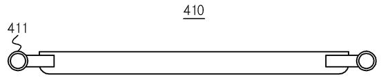
- Figure 4 is a reference diagram for the heating skate of the triplex self-adhesive apparatus of the present application according to an embodiment of the present invention.
- FIG. 5 is a control flowchart of an embodiment of a control method of a triplex self-adhesive device of the present application according to FIG. 1.
- first and second are intended to distinguish one component from another component, and the scope of rights should not be limited by these terms.
- first component may be named a second component, and similarly, the second component may also be named a first component.
- FIG. 1 is a front view of one embodiment of a triplex self-adhesive device according to the disclosed technology.
- the triplex self-adhesive device 10 may include a main frame 100, a plurality of traveling roller parts 300, at least one glue coating gun 500, and a heat pressing part 400. Can be.
- the triplex self-adhesive apparatus 10 may include a triplex jig 200, a pressure roller 600, a masking tape jig 700, a driver (not shown), a controller 900, or a sensor (not shown). At least one of the) may be further included.
- the triplex jig 200 may load the triplex 210.
- the triplex jig 200 may roll and load the triplex 210 in a circular roll form.
- the triplex 210 may be withdrawn from the triplex jig 200 and disposed on the adhesive surface to which the glue is applied.
- the triplex 210 withdrawn from the triplex jig 200 may be guided onto the bottom surface via the triplex guide roller 640 after passing through the at least one tension retaining roll 630.
- the glue applying gun 500 may apply a predetermined amount of glue to the bottom surface of the triplex 210 drawn out from the triplex jig 200.
- the glue application gun 500 may apply a predetermined amount of glue directly to the adhesive surface of the triplex 210.
- the glue application gun 500 may be located at the front end of the triplex self-adhesive apparatus 10 with a predetermined inclination angle.
- the glue application gun 500 may apply a predetermined amount of glue set by the control unit 900 to the adhesive surface or the bottom surface of the extracted triplex 210.
- the disclosed technology is applied to the adhesive surface or the bottom surface of the triplex 210, in order to attach the triplex 210 drawn from the triplex jig 200 to the adhesive surface, and then the pressure roller unit 600 and The first compression, the second compression, and the heating may be bonded to the triplex 210 through the heat compression part 400.
- the glue application gun 500 may include a press for compressing the glue, a cylindrical glue tube for loading the glue, and the outlet to which the glue is applied.
- the discharge port may be implemented in a flat shape as a fan shape that the outlet is wide. This is to have the effect that the glue loaded on the cylindrical glue tube can be applied relatively broadly and evenly to the bottom surface.
- the pressure roller 600 may primarily compress the triplex 210 to which the glue is applied, and maintain the tension of the triplex 210.
- the pressure roller unit 600 may include a pair of pressure rollers 610, a third pneumatic cylinder 620, a tension retaining roll 630 and a triplex guide roller 640.
- the pair of pressure rollers 610 may be composed of a pair of rollers having an axis parallel to the adhesive surface and rotating.
- the pair of pressure rollers 610 may be composed of a plurality of circular rollers each having an axis parallel to the adhesive surface and closely contacted with each other at predetermined intervals.
- the pressing roller portion 600 is formed in a cylindrical shape and may be formed on both ends of the guide step projections protruding from the circumferential surface, respectively.
- the pressing roller 600 may be formed as a pressing surface parallel to the bottom surface having a predetermined inclination angle at both ends.
- the third pneumatic cylinder 620 extends and is connected to an upper portion of the pair of pressure rollers 610, and adjusts the air pressure under the control of the controller 900 to press the pair of pressure rollers 610 in an adhesive surface direction. can do.
- the tension retaining roll 630 extends and is connected to an upper portion of the third pneumatic cylinder 620, and maintains a constant tension in the width direction of the triplex 210 drawn from the triplex jig 200 so that the triplex 210 is fixed. This can prevent the phenomenon of tipping.
- the tension retaining roll 630 may be formed in the form of a rolling roll.
- the triplex guide roller 640 may be positioned at the front end of the pair of pressure rollers 610 such that the masking tape 710 and the triplex 210 may be bonded to each other with a predetermined width.
- the heat compression unit 400 may heat and secondary compress the triplex 210 to which the glue is applied.
- the heating crimp 400 includes a heating skate 410, a second pneumatic cylinder 420 and a hinge (not shown) connecting the heating skate 410 and the second pneumatic cylinder 420. Can be.
- the heating crimping unit 400 uses high pressure, fewer bubbles are provided than the conventional triplex attachment device, and thus, the triplex can be more firmly attached in the adhesive force and adhesion.
- the heating skate 410 is implemented in a rectangular shape and may include a skate roller 411 as shown in FIG. 4 at the front and rear ends to improve adhesion between the triplex 210 and the bottom surface.
- Can be. 4 is a reference view of the heating skate of the triplex self-adhesive apparatus of the present application according to an embodiment of the present invention.
- the heating crimping unit 400 may compress the heating skate 410 to a predetermined temperature in the adhesive surface direction by adjusting the heating temperature or air pressure under the control of the controller 900.
- the pressing roller portion 600 and the heat pressing portion 400 may be arranged in plural in a repeating order.
- the heat pressing part 400 and the pressure roller part 600 may be a first pressure roller part and a first pressure roller that primarily compress the triplex 210 with glue by the glue coating gun 500.
- the roller unit and the second pressing roller unit may be configured as a second heat compression unit for heating and quadruple compression triplex 210.
- the hot pressing unit 400 may compress the triplex 210 at a high pressure using a cylinder of the hot pressing unit 400 regardless of the presence of the pressure roller unit 600.
- the plurality of traveling roller parts 300 may be in close contact with the side surface of the guide rail 20 fixed to the panel 30 positioned on the left and right sides of the triplex self-adhesive device 10 at a predetermined pressure.
- the plurality of traveling roller portion 300 is a pair of traveling roller 310, the first pneumatic cylinder 320, the vertical movement bar 370, the rotary gear 330, the variable member 340
- the driving guide bar 380, the driving motor 350, and the pinion gear 360 may be included.
- the plurality of traveling roller portions 300 maintain a predetermined pressure between the triplex self-adhesive device 10 and the guide rail 20 so that the triplex self-adhesive device 10 is connected to the guide rail 20. It can be in close contact.
- the plurality of running roller portion 300 may be in close contact with the guide rail 20 in accordance with the pneumatic pressure by the first pneumatic cylinder (320).
- the plurality of travel roller portion 300 may be located in front and rear of the triplex self-adhesive apparatus 10, respectively.
- the pair of travel rollers 310 are a pair of travel rollers 310 which are varied by the first pneumatic cylinder 320.
- the pair of traveling rollers 310 may be in close contact with the guide rail 20 at a predetermined pressure.
- the pair of travel rollers 310 may have a predetermined groove that can engage one end of the guide rail 20.
- the first pneumatic cylinder 320 extends at one end of the vertical movement bar 370.
- the first pneumatic cylinder 320 may move the vertical movement bar 370 up and down according to the air pressure controlled by the controller 900.
- the vertical movement bar 370 has predetermined irregularities in the body. In one embodiment, it extends with one end of the first pneumatic cylinder 320 may move up and down according to the vertical movement of the piston.
- the vertical movement bar 370 may be composed of a predetermined gear and cog wheels for the vertical movement and to rotate the rotary gear 330.
- the rotary gear 330 is in close contact with one end of the vertical movement bar 370 and the variable member 340.
- the rotary gear 330 may be configured in the form of a sawtooth so that the variable member 340 moves to the left or right by converting the vertical movement of the vertical movement bar 370 to the rotary movement.
- variable member 340 extends with the pair of travel rollers 310, and moves to the left or right according to the fire of the rotary gear 330 to variably move the pair of travel rollers 310 in the width direction. You can.
- the driving guide bar 380 of the manual clamping method may prevent the falling of the equipment when the plurality of traveling roller parts 300 are separated from the guide rail 20 due to a sudden pneumatic drop.
- the travel motor 350 produces power.
- the travel motor 350 may be composed of one motor or a plurality of travel motors 350 connected in series or in parallel.
- the pinion gear 360 may rotate in response to the driving motor 350.
- the pinion gear 360 is powered by the travel motor 350 to convert to rotational motion.
- the pinion gear 360 may be engaged with the rack gear 21 fixed to one end of the guide rail 20 to move the triplex self-adhesive device 10 forward and backward.
- the plurality of driving roller parts 300 and the control thereof will be described in more detail below with reference to FIG. 5.
- the triplex self-adhesive device 10 may include a sensor unit (not shown).
- the sensor unit may include an orientation sensor or a gyro sensor, and may generate orientation information by detecting an inclination angle of the triplex self-adhesive device 10 with respect to the ground.
- the masking tape jig 700 may load the masking tape 710.
- the masking tape jig 700 may roll the masking tape 710 in a roll form.
- the masking tape 710 may be withdrawn from the masking tape jig 700 and adhered to the top surface of the triplex 210.
- the masking tape 710 drawn out from the masking tape jig 700 may be guided to the top surface of the triplex 210 via the triplex guide roller 640 and then bonded.
- the control unit 900 is responsible for the control of the triplex self-adhesive apparatus 10.
- the controller 900 may generate posture information using the orientation information provided by the sensor unit.
- the posture information may be information representing a current posture of the triplex self-adhesive device 10.
- the posture information may be represented by any one of the ground, the wall, or the ceiling, and may further include information about a predetermined inclination angle.
- the posture information is a wall surface, it means a state in which the triplex self-adhesive device 10 travels along a wall surface formed at a predetermined angle and attaches the triplex.
- control unit 900 may store data on the pressing range of the posture information for each component, and checks the pressing range of the current posture according to the posture information to determine the pressing range of the other components based on this. Can be controlled.
- the data on the pressurization range may have a different pressurization range according to the range of the inclination angle even when traveling on the wall, and the control unit 900 may detect the pressurization range when a pressure below or exceeding the pressurization range is detected. The pressure can be controlled to pressurize or depressurize to be satisfied.
- FIG. 2 is a reference view of an embodiment of a plurality of traveling roller parts of the triplex self-adhesive apparatus according to FIG. 1.
- one embodiment of the triplex self-adhesive apparatus disclosed in FIG. 2 illustrates a state (b) in close contact with a state (a) in which the guide rails 20 and the plurality of traveling roller parts 300 are spaced apart from each other. Doing. For example, (a) before the triplex self-adhesive device 10 starts to be driven for the first time or when the width of the guide rail 20 is widened, (b) the triplex self-adhesive device 10 is initially driven. If you are doing or in progress may be in the same state as the example shown.
- Figure 3 is a reference diagram showing a guide rail of the triplex self-adhesive apparatus of the present application according to an embodiment of the present invention.
- the guide rails 20 may be attached side by side at one end of the upper portion of the insulation panel 30.
- the guide rail 20 may be fastened to the insulation panel 30 by using a screw hole for assembling a fixing support used for fixing the airbag used in the manual method.
- the black dots regularly arranged on the insulation panel 30 may be screw holes for assembling the fixing support used for fixing the airbags used in the manual method, and the present invention provides such a method.
- the guide rail 20 can be bound to the heat insulation panel 30 by utilizing the screw hole.
- the process for attaching the guide rail 20 is very simple, so the installation efficiency is high, and the guide rail 20 can be more firmly bound to facilitate the load of the triplex automatic attachment device 10. There is an effect that can be sustained.
- FIG. 5 is a flowchart according to an embodiment of a control method of a triplex self-adhesive apparatus.
- the self-adhesive device 10 may display posture information of the current self-adhesive device 10. Collect (S410), the pressure range can be confirmed based on the collected posture information (S420).
- the self-adhesive apparatus 10 may control the first pneumatic cylinder so as to satisfy the pressure range in the lateral direction to closely contact the pair of traveling rollers of the self-adhesive apparatus 10 to the guide rail (S430).
- the self-adhesive device 10 After the self-adhesive device 10 is driven in the forward direction (S440), the self-adhesive device 10 checks the pressurized state of the driving device to control the first pneumatic cylinder 320 so as to be suitable for the pressurized range in the lateral direction even while driving. It may be (S450).
- the self-adhesive device 10 may compress the heating skate 410 using the transverse pressure range.
- the self-adhesive apparatus 10 checks the lateral pressurization range according to the posture based on the collected posture information, and controls the second pneumatic cylinder 420 to satisfy the lateral pressurization range so that the triplex automatic The heating skate of the heat pressing portion of the bonding device may be pressed onto the bottom surface (S460).
- the self-adhesive apparatus 10 may check the pressure changed in accordance with the running, and pressurize or reduce the predetermined pressure to the changed pressure so as to fit in the transverse pressure range.
Landscapes
- Engineering & Computer Science (AREA)
- Architecture (AREA)
- General Engineering & Computer Science (AREA)
- Civil Engineering (AREA)
- Structural Engineering (AREA)
- Chemical & Material Sciences (AREA)
- Combustion & Propulsion (AREA)
- Mechanical Engineering (AREA)
- Ocean & Marine Engineering (AREA)
- Adhesives Or Adhesive Processes (AREA)
- Coating Apparatus (AREA)
- Lining Or Joining Of Plastics Or The Like (AREA)
Description
Claims (10)
- 액화천연가스 운반선의 화물창의 내부에 고정되고 좌 또는 우측 상면에 가이드 레일이 고정된 단열 패널을 따라 이동하며 바닥면에 트리플렉스를 부착하는 트리플렉스 자동 접착 장치에 있어서,메인 프레임;상기 메인 프레임에 고정되며, 상기 가이드 레일의 내측 면에 소정의 압력으로 밀착하여 상기 트리플렉스 자동 접착 장치를 지탱하는 복수의 주행 롤러부들;상기 트리플렉스 자동 접착 장치의 구동에 따라 바닥면에 소정 양의 글루를 도포하는 적어도 하나의 글루 도포건부; 및상기 적어도 하나의 글루 도포건부에 의하여 도포된 글루 위에 배치되는 상기 트리플렉스를 소정의 압력 또는 온도로 가열 압착하는 가열 압착부를 포함하는 트리플렉스 자동 접착 장치.
- 제1항에 있어서, 상기 복수의 주행 롤러부들은상기 가이드 레일의 내측 면에 일정한 압력으로 밀착되어 회전하는 한 쌍의 주행 롤러들;공압 제어 밸브에 의하여 압력 값을 변화시키고, 상기 변화된 압력 값에 따라 피스톤을 전, 후진 시키는 공압 실린더;상기 공압 실린더의 양측 하단에 밀착되어, 상기 피스톤의 전, 후진 운동을 회전운동으로 전환하는 회전 기어; 및상기 한 쌍의 주행 롤러들의 중심축과 결합되며, 상기 회전 기어와 맞물려 상기 회전 기어의 회전운동에 따라 좌 또는 우측으로 방향으로 가변 이동되는 한 쌍의 가변부재를 포함하는 것을 특징으로 하는 트리플렉스 자동 접착 장치.
- 제1항에 있어서, 상기 복수의 주행 롤러부들은상기 메인 프레임의 전단부 및 후단부에 각각 고정되는 것을 특징으로 하는 레일 주행 방식의 트리플렉스 자동 접착 장치.
- 제1항에 있어서, 상기 트리플렉스 자동 접착 장치는상기 가열 압착부의 전방에 위치하여, 상기 바닥면에 도포된 글루 위에 배치되는 상기 트리플렉스를 소정의 압력으로 1차 압착하는 적어도 하나의 가압 롤러부를 더 포함하고,상기 가열 압착부는 상기 적어도 하나의 가압 롤러부들에 의하여 1차 압착된 트리플렉스를 소정의 압력 또는 온도로 2차 압착 또는 가열하는 것을 특징으로 하는 트리플렉스 자동 접착 장치.
- 제1항에 있어서, 상기 가열 압착부는소정의 온도를 유지하고 상기 트리플렉스에 직접 접촉하는 판형의 히팅 스케이트;피스톤의 전방 또는 후방 운동에 따라 소정의 압력을 가압 또는 감압할 수 있는 제2 공압 실린더; 및상기 히팅 스케이트와 상기 제2 공압 실린더를 연결하여, 상기 제2 공압 실린더의 압력을 상기 히팅 스케이트에 전달하는 힌지를 포함하는 것을 특징으로 하는 트리플렉스 자동 접착 장치.
- 제5항에 있어서, 상기 히팅 스케이트는전단과 후단에 롤러가 포함되는 것을 특징으로 하는 트리플렉스 자동 접착 장치.
- 제4항에 있어서, 상기 적어도 하나의 가압 롤러부는원통형으로 구성되고 양측 끝단에 각각 원주면에서 돌출되는 가이드 단턱이 형성되는 것을 특징으로 하는 트리플렉스 자동 접착 장치.
- 액화천연가스 운반선의 화물창의 내부에 고정되고 좌 또는 우측 상면에 가이드 레일이 고정된 단열 패널을 따라 이동하며 바닥면에 트리플렉스를 부착하는 트리플렉스 자동 접착 장치에서 수행되는 트리플렉스 자동 접착 장치의 제어 방법에 있어서,(a) 상기 트리플렉스 자동 접착 장치의 자세 정보를 수집하고, 수집된 자세 정보를 기초로 자세에 따른 횡방향 가압 범위를 확인하는 단계;(b) 상기 횡 방향 가압 범위를 만족하도록 제1 공압 실린더를 제어하여 상기 트리플렉스 자동 접착 장치의 가이드 롤러를 가이드 레일에 밀착시키는 단계; 및(c) 상기 트리플렉스 자동 접착 장치를 주행시키고, 주행 중의 상기 트리플렉스 자동 접착 장치의 가압 상태를 확인하여 주행 중에도 상기 횡 방향 가압 범위를 만족하도록 상기 제1 공압 실린더를 제어하는 단계를 포함하는 트리플렉스 자동 접착 장치의 제어 방법.
- 제8항에 있어서, 상기 (c) 단계는상기 트리플렉스 자동 접착 장치의 주행에 따라 변화된 압력을 확인하는 단계; 및상기 횡방향 가압 범위를 적합하도록, 상기 변화된 압력에 소정의 압력을 가압 또는 감압하는 단계를 포함하는 것을 특징으로 하는 트리플렉스 자동 접착 장치.
- 제8항에 있어서, 상기 트리플렉스 자동 접착 장치의 제어 방법은(d) 상기 수집된 자세 정보를 기초로 자세에 따른 횡 방향 가압 범위를 확인하고, 상기 횡 방향 가압 범위를 만족하도록 제1 공압 실린더를 제어하여 상기 트리플렉스 자동 접착 장치의 가열 압착부를 바닥면으로 압착시키는 단계를 더 포함하는 것을 특징으로 하는 트리플렉스 자동 접착 장치의 제어 방법.
Priority Applications (2)
| Application Number | Priority Date | Filing Date | Title |
|---|---|---|---|
| CN201280072655.9A CN104245493B (zh) | 2012-02-28 | 2012-12-27 | 用于自动附接三层体的装置及其控制方法 |
| JP2014559816A JP6182163B2 (ja) | 2012-02-28 | 2012-12-27 | トリプレックス自動接着装置及びその制御方法 |
Applications Claiming Priority (2)
| Application Number | Priority Date | Filing Date | Title |
|---|---|---|---|
| KR10-2012-0020229 | 2012-02-28 | ||
| KR1020120020229A KR101369117B1 (ko) | 2012-02-28 | 2012-02-28 | 트리플렉스 자동 접착 방법 및 이를 수행하는 트리플렉스 자동 접착 장치 |
Publications (1)
| Publication Number | Publication Date |
|---|---|
| WO2013129765A1 true WO2013129765A1 (ko) | 2013-09-06 |
Family
ID=49082926
Family Applications (1)
| Application Number | Title | Priority Date | Filing Date |
|---|---|---|---|
| PCT/KR2012/011654 Ceased WO2013129765A1 (ko) | 2012-02-28 | 2012-12-27 | 트리플렉스 자동 접착 장치 및 그 제어 방법 |
Country Status (4)
| Country | Link |
|---|---|
| JP (1) | JP6182163B2 (ko) |
| KR (1) | KR101369117B1 (ko) |
| CN (1) | CN104245493B (ko) |
| WO (1) | WO2013129765A1 (ko) |
Families Citing this family (8)
| Publication number | Priority date | Publication date | Assignee | Title |
|---|---|---|---|---|
| US9437967B2 (en) | 2011-12-30 | 2016-09-06 | Bedrock Automation Platforms, Inc. | Electromagnetic connector for an industrial control system |
| KR102203986B1 (ko) * | 2019-03-12 | 2021-01-18 | 한국조선해양 주식회사 | 반자동 접착 장치 |
| CN111571741B (zh) * | 2020-05-13 | 2024-05-24 | 广东豪德数控装备股份有限公司 | 自动封边机一体式双轴涂胶机构 |
| CN111774252B (zh) * | 2020-05-21 | 2021-05-18 | 无锡宏义高分子材料科技有限公司 | 一种装饰用pvc电镀胶布绝缘装置 |
| FR3126322B1 (fr) * | 2021-08-24 | 2026-04-17 | Gaztransport Et Technigaz | Dispositif d’encollage pour système automatisé d’application de bande pour l’étanchéité d’une membrane de cuve |
| CN115897950A (zh) * | 2021-08-27 | 2023-04-04 | 广东博智林机器人有限公司 | 辊涂执行装置及辊涂作业设备 |
| CN113786959A (zh) * | 2021-09-23 | 2021-12-14 | 义乌市赛山贸易有限公司 | 一种防盗门充胶方法 |
| KR102764427B1 (ko) * | 2022-04-05 | 2025-02-11 | (주)로멕스테크놀로지 | 자동시트장력유지장치가 형성된 시트자동본딩장치 |
Citations (5)
| Publication number | Priority date | Publication date | Assignee | Title |
|---|---|---|---|---|
| KR20090004182A (ko) * | 2007-07-06 | 2009-01-12 | 삼성중공업 주식회사 | 자동 본딩 장치 |
| KR20090100120A (ko) * | 2008-03-19 | 2009-09-23 | 현대중공업 주식회사 | 쏠림 방지기능을 갖는 트리플렉스 자동부착장치 |
| KR20100029965A (ko) * | 2008-09-09 | 2010-03-18 | 현대중공업 주식회사 | 원적외선 히터를 갖는 트리플렉스 자동부착장치 |
| KR20100079880A (ko) * | 2008-12-31 | 2010-07-08 | 삼성중공업 주식회사 | 자동 본딩 장치 |
| KR20110028076A (ko) * | 2009-09-11 | 2011-03-17 | 삼성중공업 주식회사 | 트리플렉스 자동부착장치 |
Family Cites Families (5)
| Publication number | Priority date | Publication date | Assignee | Title |
|---|---|---|---|---|
| JPH08105843A (ja) * | 1994-10-06 | 1996-04-23 | Japan Steel & Tube Constr Co Ltd | 貯槽内壁溶接部の検査方法及びその自動検査装置 |
| FR2822815B1 (fr) * | 2001-03-27 | 2003-10-31 | Gaz Transport & Technigaz | Machine pour le collage d'une bande, procede de collage d'une bande pour la realisation d'une paroi isolante et etanche, et paroi isolante et etanche |
| KR100889903B1 (ko) * | 2004-12-17 | 2009-03-20 | 현대중공업 주식회사 | 액화천연가스 운반선 화물창의 트리플렉스 자동접착장치 |
| KR101302208B1 (ko) * | 2006-12-19 | 2013-09-10 | 삼성중공업 주식회사 | 레일방식의 주행장치 |
| CN201094948Y (zh) * | 2007-09-25 | 2008-08-06 | 李冬来 | 花边带涂胶机 |
-
2012
- 2012-02-28 KR KR1020120020229A patent/KR101369117B1/ko active Active
- 2012-12-27 WO PCT/KR2012/011654 patent/WO2013129765A1/ko not_active Ceased
- 2012-12-27 JP JP2014559816A patent/JP6182163B2/ja active Active
- 2012-12-27 CN CN201280072655.9A patent/CN104245493B/zh active Active
Patent Citations (5)
| Publication number | Priority date | Publication date | Assignee | Title |
|---|---|---|---|---|
| KR20090004182A (ko) * | 2007-07-06 | 2009-01-12 | 삼성중공업 주식회사 | 자동 본딩 장치 |
| KR20090100120A (ko) * | 2008-03-19 | 2009-09-23 | 현대중공업 주식회사 | 쏠림 방지기능을 갖는 트리플렉스 자동부착장치 |
| KR20100029965A (ko) * | 2008-09-09 | 2010-03-18 | 현대중공업 주식회사 | 원적외선 히터를 갖는 트리플렉스 자동부착장치 |
| KR20100079880A (ko) * | 2008-12-31 | 2010-07-08 | 삼성중공업 주식회사 | 자동 본딩 장치 |
| KR20110028076A (ko) * | 2009-09-11 | 2011-03-17 | 삼성중공업 주식회사 | 트리플렉스 자동부착장치 |
Also Published As
| Publication number | Publication date |
|---|---|
| KR101369117B1 (ko) | 2014-03-06 |
| JP2015515407A (ja) | 2015-05-28 |
| CN104245493A (zh) | 2014-12-24 |
| JP6182163B2 (ja) | 2017-08-16 |
| CN104245493B (zh) | 2017-03-08 |
| KR20130098598A (ko) | 2013-09-05 |
Similar Documents
| Publication | Publication Date | Title |
|---|---|---|
| WO2013129765A1 (ko) | 트리플렉스 자동 접착 장치 및 그 제어 방법 | |
| CN112171637B (zh) | 用于矿下电缆巡检的机器人线缆行走机构及方法 | |
| CN108622118B (zh) | 一种用于管廊巡检的机器人 | |
| WO2011071231A2 (ko) | 필름 부착장치 및 부착방법 | |
| CN114527590A (zh) | 一种液晶显示面板与背光模组的组装贴合设备 | |
| KR100993639B1 (ko) | 액화천연가스 운반선 화물창용 트리플렉스 자동 접착 장치 | |
| KR101130641B1 (ko) | 트리플렉스 자동부착장치 | |
| WO2013133523A1 (ko) | 트리플렉스 자동 부착 장치 | |
| CN205275042U (zh) | 一种具有锥辊快换装置的电缆拖令 | |
| CN117262825A (zh) | 一种膜输送的物料小车 | |
| CN110926306A (zh) | 一种导向轮轴检测装置 | |
| KR101365903B1 (ko) | 레일 주행 구동장치 및 그 제어 방법 | |
| KR20210093530A (ko) | 간봉 테이프 부착 장치 | |
| CN216548905U (zh) | 在条状件上布双面胶带的装置 | |
| WO2012033292A2 (ko) | 패널 부착 장치 | |
| CN209480923U (zh) | 剥料装置 | |
| KR101194761B1 (ko) | 윈치 장치 및 이를 구비한 자동 본딩 장치 | |
| CN209351625U (zh) | 一种无人机动力性能测试系统 | |
| KR101452333B1 (ko) | 이동로봇을 이용한 케이블 코팅장치 | |
| CN210703512U (zh) | 轴承座拆装装置 | |
| CN218472496U (zh) | 防污染滑触线支架 | |
| CN119160735B (zh) | 一种电梯制动安全用防滑型电梯安全钳及其使用方法 | |
| CN218309020U (zh) | 一种带传送带驱动组件的涂漆机台 | |
| WO2010058897A2 (ko) | 라벨 부착장치 및 부착방법 | |
| CN117719966A (zh) | 一种全自动绳头连接装置 |
Legal Events
| Date | Code | Title | Description |
|---|---|---|---|
| 121 | Ep: the epo has been informed by wipo that ep was designated in this application |
Ref document number: 12869963 Country of ref document: EP Kind code of ref document: A1 |
|
| ENP | Entry into the national phase |
Ref document number: 2014559816 Country of ref document: JP Kind code of ref document: A |
|
| NENP | Non-entry into the national phase |
Ref country code: DE |
|
| 32PN | Ep: public notification in the ep bulletin as address of the adressee cannot be established |
Free format text: NOTING OF LOSS OF RIGHTS PURSUANT TO RULE 112(1) EPC (EPO FORM 1205A DATED 16/12/2014) |
|
| 122 | Ep: pct application non-entry in european phase |
Ref document number: 12869963 Country of ref document: EP Kind code of ref document: A1 |