WO2013129665A1 - 標的物質捕捉装置およびそれを備えた標的物質検出装置 - Google Patents
標的物質捕捉装置およびそれを備えた標的物質検出装置 Download PDFInfo
- Publication number
- WO2013129665A1 WO2013129665A1 PCT/JP2013/055738 JP2013055738W WO2013129665A1 WO 2013129665 A1 WO2013129665 A1 WO 2013129665A1 JP 2013055738 W JP2013055738 W JP 2013055738W WO 2013129665 A1 WO2013129665 A1 WO 2013129665A1
- Authority
- WO
- WIPO (PCT)
- Prior art keywords
- metal film
- target substance
- photonic crystal
- light
- boundary portion
- Prior art date
- Legal status (The legal status is an assumption and is not a legal conclusion. Google has not performed a legal analysis and makes no representation as to the accuracy of the status listed.)
- Ceased
Links
Images













Classifications
-
- G—PHYSICS
- G01—MEASURING; TESTING
- G01N—INVESTIGATING OR ANALYSING MATERIALS BY DETERMINING THEIR CHEMICAL OR PHYSICAL PROPERTIES
- G01N21/00—Investigating or analysing materials by the use of optical means, i.e. using sub-millimetre waves, infrared, visible or ultraviolet light
- G01N21/17—Systems in which incident light is modified in accordance with the properties of the material investigated
- G01N21/47—Scattering, i.e. diffuse reflection
- G01N21/4738—Diffuse reflection, e.g. also for testing fluids, fibrous materials
Definitions
- the present invention relates to a target substance capturing device that detects a target substance and a target substance detection device including the target substance capturing device.
- Biosensors using photonic crystals are known as means for detecting target substances such as proteins and cells and measuring concentrations (for example, Non-Patent Document 1).
- the biosensor described in Non-Patent Document 1 irradiates light on a photonic crystal substrate on which a gold thin film is formed, and measures a change in the wavelength peak of reflected light reflected by the photonic crystal substrate.
- the target substance is detected and the concentration of the target substance is measured.
- the biosensor described in Non-Patent Document 1 since the biosensor described in Non-Patent Document 1 has a wide spectrum shape of the wavelength of reflected light and the peak intensity of the wavelength is low, it may be difficult to specify the peak wavelength. For this reason, the biosensor described in Non-Patent Document 1 may reduce the detection accuracy of the target substance.
- An object of the present invention is to provide a target substance capturing device that can detect a target substance with high accuracy and a target substance detection device including the target substance capturing device.
- the present invention includes a structure in which a surface in which concave portions are periodically formed is coated with a metal film and has a reflective surface for capturing a target substance, and reflects the light irradiated on the reflective surface,
- a boundary between the wall surface of the concave portion and the bottom surface of the concave portion is a first boundary portion
- a boundary between the surface and the wall surface of the concave portion is a second boundary portion
- An intersection point of a straight line passing through the first boundary portion in a direction perpendicular to the surface and a straight line passing through the second boundary portion in a direction horizontal to the surface is defined as an intersection A
- the first boundary portion and the second The distance connecting the boundary portion with a straight line is L1, the distance connecting the first boundary portion and the intersection A with a straight line is L2, the distance connecting the second boundary portion and the intersection A with a straight line is L3, When the angle formed by the L1
- This target substance detection device is formed so that the shape of the recess satisfies the above formulas (1) and (2).
- the spectrum shape of the wavelength of the reflected light becomes narrow. For this reason, the target substance can be detected with high accuracy.
- the present invention includes a structure in which convex portions are periodically formed on the surface and covered with a metal film, and has a reflective surface for capturing a target substance, and reflects the light irradiated on the reflective surface,
- a boundary between the wall surface of the convex portion and the surface is defined as a first boundary portion
- a boundary between the tip surface and the wall surface of the convex portion is defined as a second boundary.
- An intersection point between a straight line passing through the first boundary portion in a direction perpendicular to the tip surface and a straight line passing through the second boundary portion in a direction horizontal to the tip surface is defined as an intersection point A ′.
- This target substance detection device is formed so that the shape of the convex portion satisfies the above formulas (3) and (4).
- the spectrum shape of the wavelength of the reflected light becomes narrow. For this reason, the target substance can be detected with high accuracy.
- the present invention includes a structure in which a surface in which concave portions are periodically formed is coated with a metal film and has a reflective surface for capturing a target substance, and reflects the light irradiated on the reflective surface,
- the deepest portion is a first boundary portion
- a boundary between the surface and the wall surface of the recess is a second boundary portion
- the direction perpendicular to the surface An intersection point of a straight line passing through the first boundary part and a straight line passing through the second boundary part in the horizontal direction with respect to the surface is defined as an intersection point A ′′
- the first boundary part and the second boundary part are defined by a straight line.
- the connecting distance is L11
- the distance connecting the first boundary portion and the intersection A ′′ with a straight line is L12
- the distance connecting the second boundary portion and the intersection A ′′ with a straight line is L13
- the L11 And the angle formed by L12 is ⁇ ′′
- This target substance detection device is formed so that the shape of the recess satisfies the above formulas (5) and (6).
- the spectrum shape of the wavelength of the reflected light becomes narrow. For this reason, the target substance can be detected with high accuracy.
- the present invention includes a structure in which convex portions are periodically formed on the surface and covered with a metal film, and has a reflective surface for capturing a target substance, and reflects the light irradiated on the reflective surface, In a cross section passing through the deepest part of the recess of the metal film formed between the adjacent convex parts, the deepest part is the first boundary part, and the front end surface of the convex part and the convex part are flat.
- An intersection of a straight line passing through the first boundary portion in a direction perpendicular to the tip surface and a straight line passing through the second boundary portion in a direction horizontal to the tip surface with the boundary with the wall surface as a second boundary portion Is an intersection point A ′′, a distance connecting the first boundary portion and the second boundary portion with a straight line is L11 ′, and a distance connecting the first boundary portion and the intersection A ′′ with a straight line is L12 ′.
- a distance connecting the second boundary portion and the intersection A ′′ with a straight line is L13 ′, and L11 ′ and L12 ′
- the convex portion is represented by the following formula (7), which is the target substance capturing apparatus characterized by being formed so as to satisfy (8).
- This target substance detection device is formed so that the shape of the recess satisfies the above formulas (7) and (8).
- the spectrum shape of the wavelength of the reflected light becomes narrow. For this reason, the target substance can be detected with high accuracy.
- a target substance capturing substance for capturing the target substance is fixed to the reflecting surface. By doing in this way, a target substance can be easily capture
- the reflecting surface on which a certain amount of the target substance of the same type as the target substance to be detected is fixed has a known amount of the target substance capturing substance and the detection target that specifically react with the target substance fixed on the reflecting surface. It is preferable that the target substance is brought into contact with a mixture of the target substance and the sample containing the target substance to be detected. By doing in this way, since the change of the surface state of a reflective surface can be enlarged more, a target substance can be detected more accurately.
- the metal film preferably has a thickness of 30 nm to 1000 nm.
- the structure is preferably a photonic crystal.
- the distance between the centers of the convex portions or the distance between the centers of the concave portions is preferably 400 nm or more and 800 nm or less.
- the distance between the centers of the convex portions or the distance between the centers of the concave portions is preferably 560 nm or more and 720 nm or less.
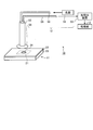
- FIG. 1 is a diagram illustrating a target substance detection device.
- FIG. 2 is a perspective view of a metal film-coated photonic crystal.
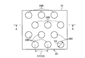
- FIG. 3 is a plan view of the metal film-coated photonic crystal.
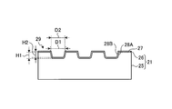
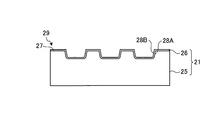
- FIG. 4 is a diagram showing a cross section along AA in FIG.
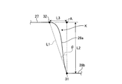
- FIG. 5 is a partially enlarged view of the wall surface of the concave portion of the metal film-coated photonic crystal.
- FIG. 6 is a partially enlarged view of the wall surface of another concave portion of the metal film-coated photonic crystal.
- FIG. 7 is a diagram showing the reflectance with respect to the peak wavelength (spectrum) of Example 1.
- FIG. FIG. 8 is a diagram showing the reflectance with respect to the peak wavelength (spectrum) of the second embodiment.
- FIG. 1 is a diagram illustrating a target substance detection device.
- FIG. 2 is a perspective view of a metal film-coated photonic crystal.
- FIG. 3 is a plan view of the metal
- FIG. 9 is a diagram showing the relationship between time and peak wavelength (spectrum) in Example 1 and Example 2.
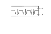
- FIG. 10 is a diagram illustrating a method for manufacturing a photonic crystal.
- FIG. 11 is a diagram illustrating a method for manufacturing a photonic crystal.
- FIG. 12 is a diagram illustrating a method for manufacturing a photonic crystal.
- FIG. 13 is a diagram for explaining the principle of the photonic crystal biosensor.
- FIG. 14 is a diagram for explaining the principle of a photonic crystal biosensor.
- FIG. 15 is a diagram for explaining the principle of the photonic crystal biosensor.
- FIG. 16 is a diagram for explaining the principle of the photonic crystal biosensor.
- FIG. 17 is a diagram illustrating a photonic crystal biosensor.
- FIG. 10 is a diagram illustrating a method for manufacturing a photonic crystal.
- FIG. 11 is a diagram illustrating a method for manufacturing a photonic crystal.
- FIG. 12 is a diagram illustrating a method for
- FIG. 18 is a diagram illustrating a photonic crystal biosensor.
- FIG. 19 is a diagram illustrating a photonic crystal biosensor.
- FIG. 20 is a diagram for explaining a photonic crystal biosensor fixing means.
- FIG. 21 is a diagram for explaining the photonic crystal biosensor fixing means.
- FIG. 22 is a diagram illustrating another embodiment of the photonic crystal biosensor.
- FIG. 23 is a diagram illustrating an example in which the light detection unit of the target substance detection device irradiates light to the photonic crystal biosensor.
- FIG. 24 is a diagram illustrating a structure of a measurement probe included in the light detection unit of the target substance detection device.
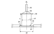
- FIG. 25 is a diagram illustrating the evaluation conditions of the light detection unit of the target substance detection device.
- FIG. 24 is a diagram illustrating a structure of a measurement probe included in the light detection unit of the target substance detection device.
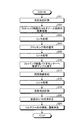
- FIG. 26 is a flowchart of the target substance detection method.
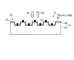
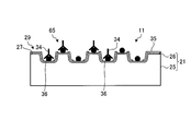
- FIG. 27 is a diagram for explaining the principle of a photonic crystal biosensor.
- FIG. 28 is a diagram for explaining the principle of a photonic crystal biosensor.
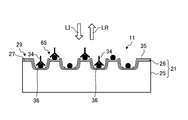
- FIG. 29 is a diagram illustrating the principle of a photonic crystal biosensor.
- FIG. 30 is a diagram for explaining the principle of the photonic crystal biosensor.
- FIG. 31 is a diagram for explaining the principle of a photonic crystal biosensor.
- FIG. 32 is a perspective view of a metal film-coated photonic crystal.
- FIG. 33 is a view showing a cross section when the photonic crystal is cut along a plane orthogonal to the surface of the metal film-coated photonic crystal.
- FIG. 34 is a partially enlarged view of the wall surface of the convex portion of the metal film-coated photonic crystal.
- FIG. 35 is a diagram showing a cross section passing through the deepest portion of the concave portion of the metal film-coated photonic crystal.
- FIG. 36 is a partially enlarged view of the wall surface of the recess of the metal film-coated photonic crystal of FIG.
- FIG. 37 is a diagram showing a cross section passing through the deepest portion of the depression of the metal film-coated photonic crystal.
- FIG. 38 is a partially enlarged view of protrusions of the metal film-coated photonic crystal of FIG.
- FIG. 39 is a diagram showing the relationship between the reflection spectrum and the reflectance when light is applied to the metal film used for the photonic crystal.
- FIG. 40 is a diagram showing the relationship between the reflection spectrum and the reflectance when light is irradiated on the metal film used for the photonic crystal.
- FIG. 41 is a diagram showing the relationship between the distance between the centers of the convex portions or concave portions of the metal-coated photonic crystal and the peak wavelength.
- FIG. 42 is a diagram showing the relationship between the distance between the centers of the convex portions or concave portions of the metal-coated photonic crystal and the sensitivity.
- the photonic crystal 25 has a reflecting surface 29 in which concave portions 28A are periodically formed on the surface 27.
- the reflection surface 29 is irradiated with light, light having a specific wavelength depending on the shape and material of the photonic crystal 25 is reflected.
- the shape and dimensions of the photonic crystal 25 are not limited to the shapes shown in FIGS. For example, a rectangular or polygonal lattice pattern formed on the surface, or a parallel line pattern or corrugated pattern formed on the surface (specifically, a pattern or the like formed periodically) ), Or a combination of these patterns.
- an organic material such as a synthetic resin or an inorganic material such as a metal or ceramic can be used.
- ceramics such as silica, alumina, zirconia, titania and yttria can be suitably used.
- the photonic crystal 25 is produced by performing fine processing on the surface of the material substrate.
- a processing method laser processing, thermal nanoimprint, optical nanoimprint, a combination of a photomask and etching, or the like can be used.
- a thermoplastic resin such as a polycycloolefin-based synthetic resin
- a method using thermal nanoimprinting is preferable.
- the reflective surface 29 of the photonic crystal 25 is covered with a metal film 26.
- the metal film 26 is preferably formed using at least one of gold (Au), silver (Ag), platinum (Pt), and aluminum (Al).
- the metal film 26 is made of Au.
- Au is preferable as the reflective surface 29 because it is excellent in stability.
- the surface is preferably covered with gold. By doing in this way, the usage-amount of gold
- the thickness of the metal film 26 is small, part of the incident light on the photonic crystal 25 may pass through the metal film 26. As a result, a large amount of unnecessary information may be included in the reflected light from the photonic crystal 25, such as a reduction in the amount of information obtained from the reflected light, diffracted light, or reflected light from the back surface of the photonic crystal 25.
- unnecessary information contained in the reflected light from the photonic crystal 25 can be reduced, and the detection accuracy and concentration measurement accuracy of the target substance can be improved. Further, it is preferable that the thickness of the metal film 26 is moderately small because a detailed pattern shape can be easily formed on the surface 27 of the photonic crystal 25.
- the thickness of the metal film 26 is preferably 30 nm or more and 1000 nm or less, more preferably 150 nm or more and 500 nm or less, and further preferably 200 nm or more and 400 nm or less. This is because the change of the reflectance with respect to the wavelength becomes almost the same when the thickness of the metal film 26 exceeds 200 nm.
- the reflective surface 29 of the photonic crystal 25 is preferably modified using 3-triethoxysilylpropylamine (APTES) or the like.
- APTES 3-triethoxysilylpropylamine
- the Au or Ag metal film 26 is formed on the reflective surface 29 of the photonic crystal 25, it is not APTES but has a thiol group at one end and a functional group such as an amino group or a carboxyl group at the other end. It is preferable to modify the reflecting surface 29 of the photonic crystal 25 using the carbon chain that it has.
- a silane coupling agent having a functional group at one end for example, APTES is used to reflect the reflective surface of the photonic crystal 25. It is preferable to modify 29.
- the distance C2 between the centers of the recesses 28B is preferably 100 nm or more and 2000 nm or less, more preferably 200 nm or more and 1000 nm or less, like the distance C1 between the centers of the recesses 28A.
- the aspect ratio (H2 / D2) of the recess 28B is preferably 0.1 or more and 10 or less, more preferably 0.5 or more and 5.0 or less. is there.
- the dimension of the recess 28B is not limited to the above.
- the boundary between the wall surface 28a and the bottom surface 28b of the recess 28B is defined as a first boundary portion 31.
- a boundary between the surface 27 and the wall surface 28 a of the recess 28 ⁇ / b> B is defined as a second boundary portion 32.
- An intersection point between a straight line passing through the first boundary portion 31 in the vertical direction with respect to the bottom surface 28b and a straight line passing through the second boundary portion 32 in the horizontal direction with respect to the bottom surface 28b is defined as an intersection point A.
- a distance connecting the first boundary portion 31 and the second boundary portion 32 with a straight line is L1.
- a distance connecting the first boundary 31 and the intersection A with a straight line is L2.
- a distance connecting the second boundary portion 32 and the intersection A with a straight line is L3.
- ⁇ be the angle formed by L1 and L2.
- an angle ⁇ formed by L1 and L2 is formed so as to satisfy the following expressions (1) and (2).
- ⁇ peak is the peak wavelength
- a 0 is the hole period
- i, j are the diffraction orders
- ⁇ m is the dielectric constant of the metal
- ⁇ d is The dielectric constant of the environment.
- the peak wavelength can be obtained if the period in which the recesses 28B are arranged is given.
- the position of the peak wavelength can be easily specified when the width of the spectrum of the peak wavelength is smaller. Therefore, when the period in which the recesses 28B are arranged is clearly given, the spectrum width of the peak wavelength is reduced, and the position of the peak wavelength is easily specified.
- the metal film-covered photonic crystal 21 has a periodic structure in which concave portions 28B are periodically formed on the reflection surface 29.
- the width of the shape of the wavelength spectrum of the reflected light becomes narrow, and the peak wavelength of the reflected light can be easily achieved. Can be specified.
- the target substance can be detected with high accuracy.
- the sensor sensitivity of the photonic crystal biosensor 11 can be increased.
- the width of the shape of the wavelength spectrum of the reflected light is a half width.
- ⁇ is 0 degree or more.
- the connection portion K between the surface 27 of the metal-coated photonic crystal 21 and the wall surface 28a of the recess 28B is approximately 90 degrees.
- the connecting portion K is approximately 90 degrees, it becomes difficult to control the shape of the metal film-covered photonic crystal 21, particularly the shape of the recess 28B. That is, it becomes difficult to obtain the desired shape of the recess 28B.
- tan ⁇ > that is, ⁇ larger than 0, since the desired shape of the recess 28B can be easily obtained.
- the metal film-covered photonic crystal 21 is washed with water having a relatively high pressure.
- the angle of the connection portion K is approximately 90 degrees, the corner is easily removed.
- the recess 28B may not have the desired shape. Since tan ⁇ > 0, that is, by making ⁇ larger than 0, the possibility that the corner of the connecting portion K can be taken can be reduced. Therefore, the concave portion 28B is preferable because it has an intended shape even after cleaning. Furthermore, since tan ⁇ > 0, that is, ⁇ is larger than 0, water can easily enter the recess 28B, so that the target substance can be reliably captured in the recess 29B.
- FIG. 6 The result of measuring the wavelength spectrum using the metal film-coated photonic crystal 21 shown in FIG.
- FIG. 6 is a partially enlarged view of the wall surface 28a of another recess 28B of the metal film-covered photonic crystal 21.
- FIG. 7 is a diagram illustrating the reflectance with respect to the wavelength of the reflected light in the first embodiment.
- FIG. 8 is a diagram illustrating the reflectance with respect to the wavelength of the reflected light according to the second embodiment.
- FIG. 9 is a diagram illustrating the relationship between time and peak wavelength in the first and second embodiments.
- tan ⁇ was about 0.31
- Example 2 tan ⁇ was about 0.71.
- the distance connecting the first boundary portion 31 and the second boundary portion 32 with a straight line is L1.
- a distance connecting the first boundary 31 and the intersection A with a straight line is L2.
- a distance connecting the second boundary portion 32 and the intersection A with a straight line is L3.
- the wavelength width is 200 nm.
- white light was used as the irradiation light.
- the reflectance is the ratio of the standard material (aluminum plate) to the reflected light intensity.
- the shape of the peak wavelength in Example 1 is narrower than that in Example 2, and the peak wavelength of the reflected light can be easily specified. Further, as shown in FIG. 9, the fluctuation of the wavelength width of the peak wavelength is smaller in the first embodiment than in the second embodiment, and the noise is less. Therefore, as in Example 2, if tan ⁇ is large, the period of the recesses 28B on the reflecting surface 29 tends to be unclear, so that the spectrum width of the peak wavelength becomes large and it becomes difficult to specify the position of the peak wavelength. It can be said that it tends to be a source of noise.
- the period of the concave portion 28B in the reflecting surface 29 becomes clearer, so that the spectrum width of the peak wavelength is reduced, and the position of the peak wavelength is easily specified. At the same time, it can be said that noise can be reduced. From this, the width of the shape of the wavelength spectrum of the reflected light is narrow, and the period of the recesses 28B in the surface 27 of the reflecting surface 29 is clear in order to easily identify the peak wavelength of the reflected light. It can be said that it is important. And it can be said that clarifying the period of the recess 28B depends on the angle at which the wall surface 28a of the recess 28B is formed with respect to the bottom surface 28b.
- the surface of the metal film-coated photonic crystal 21 is formed so that the wall surface 28a of the recess 28B satisfies the above formulas (1) and (2). Therefore, when light is applied to the reflection surface 29 of the metal film-coated photonic crystal 21, the shape of the wavelength spectrum of the reflected light becomes narrow, and the peak wavelength of the reflected light can be easily specified. Thereby, the target substance can be detected with high accuracy, and the sensor sensitivity of the photonic crystal biosensor 11 can be increased.
- FIG. 11 and FIG. 12 are diagrams for explaining a photonic crystal manufacturing method.
- a mold DI having a pattern of a nanometer-level fine structure or a nanometer-level periodic structure is used.
- the heated mold DI is pressed against the sheet-shaped resin P, pressed at a predetermined pressure for a predetermined time, and released when the surface temperature of the mold DI reaches a predetermined temperature.
- the structure and the periodic structure are transferred to the sheet-like resin P. Thereby, the photonic crystal 25 is obtained.
- the mold DI is heated to about 160 ° C., pressed at a pressure of about 12 MPa for a predetermined time, and released when the surface temperature of the mold DI reaches about 60 ° C. It is preferable.
- a metal film 26 is formed on the surface in contact with the mold DI by a sputtering or vapor deposition apparatus or the like, and the metal film-covered photonic crystal 21 is completed. .
- the target substance is an object to be detected by the target substance detection apparatus 10 and may be any of a polymer such as a protein, an oligomer, and a low molecule.
- the target substance is not limited to a single molecule, and may be a complex composed of a plurality of molecules.
- Examples of the target substance include pollutants in the atmosphere, harmful substances in water, biomarkers in the human body, and the like. Of these, cortisol and the like are preferable.
- Cortisol is a low molecular weight substance with a molecular weight of 362 g / mol.
- Cortisol is attracting attention as a substance that evaluates the degree of stress felt by humans because cortisol concentration in saliva increases when humans feel stress.
- concentration of cortisol as a target substance, for example, the degree of stress can be evaluated by measuring the concentration of cortisol contained in human saliva. If the degree of stress is evaluated, it can be determined whether or not the subject is in a stress state at a level that leads to mental illness such as depression.
- the target substance capturing substance is a substance that binds to the target substance and captures the target substance.
- the term “bonded” refers to a bond that is not chemically bonded, such as a bond by chemical adsorption or van der Waals force, in addition to the case of chemically bonding.
- the target substance capturing substance is a substance that specifically reacts with the target substance to capture the target substance, and is preferably an antibody having the target substance as an antigen.
- Specific reaction means selectively forming a complex by reversibly or irreversibly binding to a target substance, and is not limited to a chemical reaction.
- a substance that reacts specifically may exist in addition to the target substance.
- the target substance can be quantified if the affinity is very small compared to the target substance.
- an antibody using the target substance as an antigen an artificially prepared antibody, a molecule composed of a substance constituting DNA such as adenine, thymine, guanine, and cytosine, a peptide, and the like can be used.
- the target substance capturing substance is preferably a cortisol antibody.
- a known method can be employed to produce the target substance capturing substance.
- the antibody can be produced by a serum method, a hybridoma method, or a phage display method.
- Molecules composed of substances constituting DNA can be produced by, for example, the SELEX method (Systematic Evolution of Ligands by Exponential Enrichment).
- the peptide can be prepared by, for example, a phage display method.
- the target substance capturing substance does not need to be labeled with any enzyme / isotope. However, it may be labeled with an enzyme / isotope.
- the photonic crystal biosensor 11 reflects the wavelength of the reflected light due to the surface plasmon resonance phenomenon and / or the localized surface plasmon resonance phenomenon when the reflection surface 29 of the metal film-coated photonic crystal 21 is irradiated with light of a specific wavelength. Use the phenomenon of extreme values shifting.
- the photonic crystal biosensor 11 is uniformly produced by thermal nanoimprint or the like. In order for the target substance detection apparatus 10 to detect reflected light more accurately, it is preferable to accurately position the incident site and the reflected site of the light irradiated to the photonic crystal biosensor 11.
- the photonic crystal biosensor 11 may be marked with a positioning marker that displays a specific position on the reflecting surface 29.
- the marker can be attached by photolithography, sputtering, vapor deposition, a lift-off process using these, printing with ink or the like, or pattern formation by imprinting.
- the marker may be attached to either the front surface (the reflective surface 29 side) or the back surface (the opposite side of the reflective surface 29) of the photonic crystal biosensor 11 as long as the position can be read.
- the measurement part of the photonic crystal 25 may be removed and a marker may be attached to the photonic crystal 25 itself. Further, a marker may be attached to the upper plate 22 and the lower plate 23.
- the photonic crystal biosensor 11 includes the holed cover 41 and the sheet 42, thereby suppressing evaporation of the solution dropped on the opening 24 of the photonic crystal biosensor 11. For this reason, it can suppress that the density
- the photonic crystal biosensor 11 includes the holed cover 41 and the sheet 42, thereby preventing foreign matters from being mixed into the solution from the outside.
- the light detection unit 12 illustrated in FIG. 1 includes a light source 51, a measurement probe 52, a light detection device 53, a first optical fiber 54, a second optical fiber 55, and a collimator lens 56.
- the light source 51 and the measurement probe 52 are optically connected by a first optical fiber 54.
- the measurement probe 52 and the light detection device 53 are optically connected by a second optical fiber 55.
- a control device that is connected to the light source 51 and the light detection device 53 and that controls the light source 51 and processes a signal from the light detection device 53 may be provided.
- the measurement probe 52 Since the measurement probe 52 has such a structure, the incident light LI irradiated to the reflection surface 29 of the photonic crystal 25 and the reflection light LR from the reflection surface 29 are emitted from substantially the same position and are incident. Can do. While the measurement probe 52 is configured as described above, and the collimator lens 56 is used to convert the light from the measurement probe 52 into parallel light, the light detection unit 12 converts the incident light LI of parallel light onto the reflection surface 29. It can be incident vertically. At the same time, the reflected light LR reflected perpendicularly from the reflecting surface 29 can be received. By doing in this way, the measurement probe 52 can suppress the fall of reflected light intensity to the minimum, and can mainly detect the 0th-order light component of the reflected light LR.
- FIG. 25 is a diagram illustrating evaluation conditions of the light detection unit 12 of the target substance detection device 10 according to the present embodiment.
- the light detection unit 12 arranges a collimator lens 56 between the incident / exit surface 63 of the measurement probe 52 and the reflection surface 29 of the metal film-coated photonic crystal 21.
- the distance (measurement distance) between the collimating lens 56 and the reflecting surface 29 is h
- the diameter of the parallel light emitted from the collimating lens 56 is d1
- the diameter of the opening 24 through which the reflecting surface 29 of the photonic crystal 25 is exposed Is d2.
- the processing unit 13 obtains the extreme wavelength of the reflected light detected by the light detection unit 12. At the same time, the processing unit 13 detects at least the presence / absence of the target substance (for example, the antigen 36 shown in FIGS. 15, 16, and the like) based on the obtained extreme wavelength shift (amount of wavelength shift).
- the processing unit 13 is, for example, a microcomputer. There is a correlation between the amount of wavelength shift and the concentration of the target substance trapped on the reflection surface 29 of the metal film-coated photonic crystal 21. For this reason, the processing unit 13 can obtain the concentration of the target substance captured by the reflection surface 29 from the wavelength shift amount.
- a method for detecting a target substance using the target substance detection apparatus 10 shown in FIG. 1 will be described.
- a case will be described in which cortisol antibody is adsorbed on the reflective surface 29 of the metal film-coated photonic crystal 21 and cortisol in saliva is detected and measured as a target substance to be detected.
- the photonic crystal 25 a cycloolefin polymer sheet having a predetermined fine structure formed on the surface by thermal nanoimprint is cut into a predetermined size.
- step S 12 a cortisol antibody solution (cortisol antibody concentration of 1 ⁇ g / ml to 50 ⁇ g / ml) is dropped onto the reflective surface 29 of the metal film-coated photonic crystal 21.
- the photonic crystal biosensor 11 is allowed to stand at a predetermined temperature for a predetermined time or if necessary, and the cortisol antibody is adsorbed on the reflection surface 29 of the metal film-coated photonic crystal 21.
- step S13 a phosphate buffer solution (PBS: Phosphate buffered saline) is dropped onto the reflective surface 29 of the metal film-coated photonic crystal 21. Thereafter, a rinsing process is performed a plurality of times for removal by centrifugal force or the like.
- PBS Phosphate buffered saline
- step S14 skim milk is dropped as the blocking agent 35 onto the reflecting surface 29 of the photonic crystal 25, and the photonic crystal biosensor 11 is left for a predetermined time at a predetermined time or a predetermined temperature if necessary.
- the skim milk is adsorbed to the non-adsorbing portion of the cortisol antibody on the reflection surface 29 of the metal film-coated photonic crystal 21.
- step S18 the rinsing process is performed a plurality of times with a phosphate buffer solution in the same manner as the rinsing process (step S15).
- step S19 the target substance detection device 10 is used to irradiate the reflection surface 29 of the metal film-coated photonic crystal 21 with light.
- the light irradiated at this time is the same as the light irradiated on the reflecting surface 29 in step S11.
- the target substance detection device 10 measures the reflected light LR from the reflecting surface 29, for example, the spectrum of the reflected light intensity.
- the wavelength at the extreme value of the reflected light intensity of the photonic crystal biosensor 11 changes due to the influence of an antigen-antibody reaction or the like in the vicinity of the reflecting surface 29 or the reflecting surface 29. For this reason, cortisol in saliva can be detected from the difference in wavelength at the extreme value of reflected light intensity before and after the reaction, that is, the amount of wavelength shift. Further, the concentration of cortisol in saliva can be obtained from the wavelength shift amount.
- step S20 the processing unit 13 obtains the wavelength shift (wavelength shift amount) at the extreme value (minimum value) of the reflected light intensity (or reflectance) measured in step S19.
- the wavelength shift amount is, for example, the extreme value (minimum value) of the wavelength ⁇ 2 after the target material is captured on the reflective surface 29 and the reflected light intensity (or reflectance) when the target material is not captured on the reflective surface 29. ) Is the difference ⁇ 2 ⁇ 1 with respect to the wavelength ⁇ 1.
- step S21 the processing unit 13 determines that cortisol is present in saliva when there is a wavelength shift amount of a predetermined amount or more.
- the processing unit 13 determines the concentration of cortisol based on the amount of wavelength shift using, for example, a relational expression between the amount of wavelength shift and the concentration of cortisol. At this time, the relational expression is obtained in advance and stored in the storage unit of the processing unit 13.
- the wavelength shift amount is obtained using the extreme wavelength of the reflected light intensity on the reflection surface 29 in a state where the target substance is not captured, but the present invention is not limited to this.
- the wavelength shift amount may be obtained using the extreme wavelength of the intensity of the reflected light from the reflecting surface 29 after the rinsing process (step S13 or step S15) is finished. Further, when there are a plurality of extreme values in step S11 and step S19, the extreme value to be noted is appropriately selected. Then, the wavelength ⁇ 1 and the wavelength ⁇ 2 are obtained for the selected extreme value.
- the photonic crystal biosensor 11 includes the metal film-covered photonic crystal 21 in which a plurality of concave portions 28B are periodically provided on the reflection surface 29.
- the recess 28B is formed on the reflection surface 29 of the metal film-coated photonic crystal 21 so that the wall surface 28a of the recess 28B has a predetermined angle with respect to the bottom surface 28b of the recess 28B.
- the period of the concave portion 28B becomes clear, and the width (for example, half-value width) of the spectrum shape of the wavelength of the reflected light LR becomes small, so that the peak wavelength can be easily specified. Therefore, the target substance detection device 10 can accurately detect the target substance (cortisol in this example) from at least the solution.
- the metal film-covered photonic crystal 21 has the antibody 34 immobilized on the reflective surface 29, but the present invention is not limited to this, and the metal film-covered photonic crystal 21 has the reflective surface 29.
- the antibody 34 may be used without being immobilized.
- a target substance detection apparatus provided with a target substance capturing apparatus according to a second embodiment of the present invention will be described.
- the target substance capturing apparatus according to the present embodiment is different from that in which the target immobilized on the reflection surface 29 of the metal film-coated photonic crystal 21 is an antigen (target substance) 36 and the antibody 34 is adsorbed to the antigen 36. Since this is the same as that of the first embodiment, a duplicate description is omitted.
- FIGS. 27 to 31 are diagrams for explaining the principle of the photonic crystal biosensor.
- the specific reaction between the antibody 34 and the antigen 36 will be described using cortisol as the antigen 36 and an anti-cortisol antibody as the antibody 34.
- the amount of the antigen 36 immobilized on the metal film-coated photonic crystal 21 is a fixed amount.
- the antibody 34 is adsorbed to the antigen 36 fixed to the metal film-coated photonic crystal 21 to form a complex 65 (see FIGS. 29 and 30)
- the photonic crystal biosensor 11 can output the correlated physical quantity.
- the fixed amount of the antigen 36 to be fixed may be appropriately changed. For example, it can be set to an optimum amount according to the range of the amount of the antigen 36 contained in the sample S.
- the blocking agent 35 is fixed to a portion of the reflecting surface 29 where the antigen 36 is not attached.
- the reflective surface 29 of the photonic crystal 25 is irradiated with light (incident light) LI of, for example, 300 nm or more and 900 nm or less as parallel light so that the optical axis is orthogonal to the reflective surface 29.
- a wavelength at which the intensity or reflectance of the reflected light LR at this time becomes an extreme value (minimum value in this example) is ⁇ 1.
- a complex 65 is formed on the reflective surface 29 by the antigen 36 and the antibody 34 fixed on the reflective surface 29.
- light (incident light) LI of, for example, 300 nm or more and 2000 nm or less is parallel light and the optical axis is orthogonal to the reflection surface 29 on the reflection surface 29 of the metal film-covered photonic crystal 21. Irradiate.
- the wavelength at which the reflected light intensity or reflectance of the reflected light LR becomes an extreme value (a minimum value in this example) is ⁇ 2.
- the wavelength shift amount of the wavelength at which the light reflectance is an extreme value is ⁇ 2 ⁇ 1.
- the amount of wavelength shift changes according to the change in the surface state of the reflection surface 29 of the metal film-coated photonic crystal 21.
- the antigen 36 is detected and quantified.
- the photonic crystal biosensor 11 outputs an optical physical quantity. This physical quantity correlates with a change in the surface state on the reflecting surface 29 and correlates with the amount of the complex 65 formed by the antigen 36 and the antibody 34 immobilized on the reflecting surface 29.
- cortisol which is the antigen 36
- an anti-cortisol antibody which is the antibody 34
- cortisol is immobilized on the metal film-coated photonic crystal 21
- an anti-cortisol antibody which is the antibody 34
- the change in the surface state of the metal film-coated photonic crystal 21 becomes larger. The sensitivity of the nick crystal biosensor 11 is improved.
- the recess 28B is formed on the reflection surface 29 of the metal film-coated photonic crystal 21 so that the wall surface 28a of the recess 28B has a predetermined angle with respect to the bottom surface 28b of the recess 28B.
- the peak wavelength can be easily specified. For this reason, according to this embodiment, the sensitivity of the photonic crystal biosensor 11 can be further increased.
- the amount of the complex 65 becomes CX.
- the relationship between the amount of the composite 65 fixed to the reflecting surface 29 and the wavelength shift amount ⁇ is obtained in advance. From the above relational expression, the amount X of the antigen 36 can be determined by C ⁇ / k. The concentration of the antigen 36 can be determined based on the amount X of the antigen 36.
- the photonic crystal biosensor 11 fixes, for example, a secondary antibody that specifically reacts with the complex 65 as a complex binding substance to the reflection surface 29 of the metal film-coated photonic crystal 21. You may make it react with the composite_body
- the secondary antibody is brought into contact with the reflecting surface 29 of the metal film-covered photonic crystal 21 in an excessive amount than the first complex 65. Then, a secondary antibody is added to all the complexes 65 to form a second complex. By doing so, the change in the surface state of the metal film-coated photonic crystal 21 is further increased. As a result, the sensitivity of the photonic crystal biosensor 11 further increases.
- the secondary antibody may be used as it is, or may be used after adding other substances. Since the change in the surface state of the metal film-coated photonic crystal 21 increases as the secondary antibody increases, the photonic crystal biosensor 11 can be reacted with the complex 65 after adding another substance to the secondary antibody. The sensitivity is further increased.
- the reflective surface 29 after the second composite is formed is irradiated with light.
- the wavelength at which the reflected light intensity or reflectance obtained as a result is an extreme value (minimum value in this example) is ⁇ 2.
- the extreme value of interest is appropriately selected.
- the wavelength ⁇ 1 and the wavelength ⁇ 2 are obtained for the selected arbitrary extreme value.
- the photonic crystal biosensor 11 outputs an optical physical quantity. This physical quantity correlates with a change in the surface state on the reflecting surface 29 and correlates with the amount of the second complex fixed to the reflecting surface 29. Thereby, the second complex is detected and quantified. Since the amount of the second complex is the same as the amount of the complex 65, the complex 65 can be quantified.
- a target substance detection apparatus provided with a target substance capturing apparatus according to a third embodiment of the present invention will be described.
- the target substance capturing apparatus according to the present embodiment is the same as that of the first and second embodiments except that the photonic crystal 25 is changed to a photonic crystal having a reflective surface having convex portions formed periodically on the surface. Since it is the same, the overlapping description is omitted.
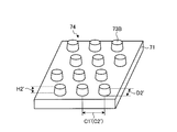
- the metal film-coated photonic crystal 71 is obtained by coating the reflective surface 74 of the photonic crystal 72 with the metal film 26, the metal film-coated photonic crystal is formed on the reflective surface 74 corresponding to the convex portion 73 ⁇ / b> A of the photonic crystal 72.
- the convex portions 73B of the crystal 71 are periodically formed.
- the convex portions 73B are arranged in a triangular lattice pattern, similarly to the convex portions 73A.
- the diameter D2 'of the convex portion 73B depends on the thickness of the metal film 26, it is preferably 50 nm or more and 1000 nm or less, and more preferably 100 nm or more and 500 nm or less.
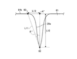
- FIG. 35 is a view showing a cross section passing through the deepest part of the recess of the metal film-covered photonic crystal
- FIG. 36 is a partially enlarged view of the wall surface of the recess of the metal film-covered photonic crystal of FIG.
- the metal film 26 provided on the reflection surface 29 of the photonic crystal 25 is omitted.
- the metal film-covered photonic crystal 81 has a substantially triangular cross section passing through the deepest portion 82 in the recess 28C.
- the recess 28A formed on the reflective surface 29 of the photonic crystal 25 includes the inside of the recess 28C.
- the cross section passing through the deepest portion 82 may be formed in a substantially triangular shape.
- the recess 28C is formed on the reflection surface 29 of the photonic crystal 25 so that the wall surface 28a of the recess 28C has a predetermined angle with respect to a horizontal straight line passing through the deepest portion 82. Therefore, the photonic crystal biosensor 11 has the concave portion 28C even when the cross section passing through the deepest portion 82 in the concave portion 28C formed by the metal film 26 on the reflection surface 29 of the photonic crystal 25 is formed in a substantially triangular shape. And the width of the shape of the spectrum of the wavelength of the reflected light (for example, the half-value width) becomes small, so that the peak wavelength can be easily specified.
- the target substance detection device 10 uses a target substance ( In this example, cortisol) can be detected with high accuracy.
- a target substance In this example, cortisol
- a target substance detection device provided with a target substance capturing device according to a fifth embodiment of the present invention will be described.
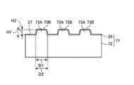
- the cross-sectional shape of the metal film 26 formed on the reflection surface 74 of the photonic crystal 72 when the photonic crystal 72 is cut along a plane orthogonal to the surface of the photonic crystal 72 is shown.
- the second embodiment is the same as the first to fourth embodiments, and a duplicate description is omitted.
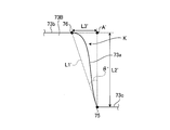
- FIG. 37 is a view showing a cross section passing through the deepest portion of the depression of the metal film-covered photonic crystal
- FIG. 38 is a partially enlarged view of the convex portions of the metal film-covered photonic crystal of FIG.
- the metal film 26 provided on the reflection surface 74 of the photonic crystal 72 is omitted.
- the metal film-covered photonic crystal 91 has a substantially triangular cross section passing through the deepest portion 93 of the recess 92 of the metal film 26 formed between the adjacent convex portions 73C. Is formed.
- the adjacent convex portions 73A of the reflective surface 74 of the photonic crystal 72 are arranged.
- the cross section passing through the deepest portion 93 of the hollow portion 92 of the metal film 26 formed in between is formed in a substantially triangular shape.
- the recessed portion 92 has a predetermined angle with respect to a horizontal straight line in which the wall surface 92 a of the recessed portion 92 passes through the deepest portion 93.
- the deepest portion 93 is defined as a first boundary portion.
- a boundary between the tip surface 73b where the convex portion 73C is flat and the wall surface of the convex portion 73C is defined as a second boundary portion 94.
- ⁇ ′′ ′′ is 0 degree or more.
- the connection portion between the tip surface 73b of the convex portion 73C of the metal film-covered photonic crystal 91 and the wall surface of the convex portion 73C is approximately 90 °.
- the connecting portion is approximately 90 degrees, it becomes difficult to control the shape of the metal film-covered photonic crystal 91, particularly the shape of the convex portion 73C. That is, it is difficult to obtain the desired shape of the convex portion 73C.
- the photonic crystal 25 it is preferable to make the photonic crystal 25 by an injection mold or imprint because a draft angle can be secured.
- the metal film-covered photonic crystal 91 is washed with water having a relatively high pressure.
- the angle of the connection portion is approximately 90 degrees, the corner is easily removed.
- the convex portion 73C may not have the desired shape.
- the metal film-covered photonic crystal 91 is obtained by coating the reflective surface 74 of the photonic crystal 72 with the metal film 26, the metal film-covered photonic crystal is formed on the reflective surface 74 corresponding to the convex portion 73 ⁇ / b> A of the photonic crystal 72.
- the convex portions 73C of the crystal 91 are periodically formed.
- the convex portions 73C are arranged in a triangular lattice pattern, similarly to the convex portions 73A.
- the diameter D3 ′ of the convex portion 73C is preferably 50 nm or more and 1000 nm or less, more preferably 100 nm or more and 500 nm or less, although it depends on the thickness of the metal film 26.
- the convex portion 73C is formed on the reflective surface 74 of the photonic crystal 72 so that the wall surface 92a of the hollow portion 92 has a predetermined angle with respect to a horizontal straight line passing through the deepest portion 93. Therefore, the photonic crystal biosensor 11 has a dent portion even when the cross section passing through the deepest portion 93 of the dent portion 92 formed by the metal film 26 on the reflection surface 74 of the photonic crystal 72 is formed in a substantially triangular shape. Since the period of 92 becomes clear and the width (for example, half-value width) of the spectrum shape of the wavelength of the reflected light becomes small, the peak wavelength can be easily specified.
- the target substance detection device 10 uses the photonic crystal biosensor 11 including the metal film-coated photonic crystal 91 in which a plurality of convex portions 73C are periodically provided on the reflection surface 74, the target substance is extracted from the solution. (In this example, cortisol) can be detected with high accuracy.
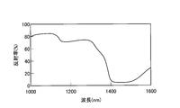
- FIG. 39 and FIG. 40 are diagrams showing the relationship between the reflection spectrum and the reflectance when the metal film used for the photonic crystal is irradiated with light.
- FIG. 41 is a diagram showing the relationship between the distance between the centers of the convex portions or concave portions of the metal-coated photonic crystal and the peak wavelength.
- FIG. 42 is a diagram showing the relationship between the distance between the centers of the convex portions or concave portions of the metal-coated photonic crystal and the sensitivity.
- the results of FIGS. 39 and 40 are measured in a water environment. White light was used as the irradiation light.
- the reflectance is the ratio of the standard material (aluminum plate) to the reflected light intensity.
- the metal-coated photonic crystal 21 and the like exhibit high reflectivity when the wavelength of irradiated light is in the range of 400 nm to 1400 nm. If the wavelength of the irradiated light is 400 nm or more, since it is a region having a wavelength higher than the ultraviolet region, damage to organic substances such as biological substances can be minimized. Moreover, if the wavelength of the irradiated light is 1400 nm or less, noise due to absorption of light by water, heat, or structure molecules can be suppressed.
- the wavelength of the light irradiated to the metal-coated photonic crystal 21 or the like is in the range of 400 nm or more and 1400 nm or less, it is possible to suppress a decrease in detection accuracy of the target substance.
- the wavelength of the irradiated light is 500 nm or more because absorption by Au can be suppressed.
- Si is used when the wavelength of irradiated light is 500 nm or more and 1000 nm or less, but InGaAs is used when the wavelength exceeds 1000 nm.
- the wavelength of the irradiated light is preferably 1000 nm or less.
- FIG. 41 is a diagram showing the relationship between the distance between the centers of the convex portions or concave portions of the metal-coated photonic crystal and the peak wavelength.
- FIG. 42 is a diagram showing the relationship between the distance between the centers of the convex portions or concave portions of the metal-coated photonic crystal and the sensitivity.
- the peak wavelength of the reflected light increases as the distance C1 between the centers of the recesses 28A shown in FIG. 3 or the distance C2 ′ between the centers of the protrusions 73B shown in FIG.
- FIG. 42 when the distance C1 between the centers of the recesses 28A shown in FIG. 3 or the distance C2 ′ between the centers of the protrusions 73B shown in FIG.
Landscapes
- Physics & Mathematics (AREA)
- Health & Medical Sciences (AREA)
- Life Sciences & Earth Sciences (AREA)
- Chemical & Material Sciences (AREA)
- Analytical Chemistry (AREA)
- Biochemistry (AREA)
- General Health & Medical Sciences (AREA)
- General Physics & Mathematics (AREA)
- Immunology (AREA)
- Pathology (AREA)
- Investigating Or Analysing Materials By Optical Means (AREA)
Description
本発明は、標的物質を検出する標的物質捕捉装置およびそれを備えた標的物質検出装置に関する。
タンパク質、細胞などの標的物質を検出したり濃度を測定したりする手段として、フォトニック結晶を用いたバイオセンサーが知られている(例えば、非特許文献1)。非特許文献1に記載されているバイオセンサーは、金薄膜を形成したフォトニック結晶基板に光を照射し、フォトニック結晶基板で反射された反射光の波長のピークの変化を測定することにより、標的物質の検出や標的物質の濃度の計測などを行っている。
「Investigation of Plasmon resonances in metal films with nanohole arrays for biosensing applications」:Takumi Sannomiya, Olivier Scholder, Konstantins Jefimovs, Christian Hafner, and Andreas B. Dahlin, Received 10th December 2010, Revised 1th February 2011
しかしながら、非特許文献1に記載されているバイオセンサーは、反射光の波長のスペクトルの形状は幅が広く、波長のピーク強度が低いため、ピーク波長の特定が困難となる可能性がある。このため、非特許文献1に記載されているバイオセンサーは、標的物質の検出精度が低下する可能性がある。
本発明は、標的物質を精度よく検出することができる標的物質捕捉装置およびそれを備えた標的物質検出装置を提供することを目的とする。
本発明は、周期的に凹部の形成されている表面が金属膜で被覆され、かつ標的物質を捕捉する反射面を有し、前記反射面に照射された光を反射する構造体を含み、前記凹部の平坦となる底面の重心を通る断面において、前記凹部の壁面と前記凹部の底面との境界を第1境界部とし、前記表面と前記凹部の壁面との境界を第2境界部とし、前記表面に対して垂直方向に前記第1境界部を通る直線と、前記表面に対して水平方向に前記第2境界部を通る直線との交点を交点Aとし、前記第1境界部と前記第2境界部とを直線で結ぶ距離をL1とし、前記第1境界部と前記交点Aとを直線で結ぶ距離をL2とし、前記第2境界部と前記交点Aとを直線で結ぶ距離をL3とし、前記L1と前記L2とが成す角度をθとするとき、前記凹部は、下記式(1)、(2)を満たすように形成されていることを特徴とする標的物質捕捉装置である。
tanθ=L3/L2 ・・・(1)
0≦tanθ≦1.0 ・・・(2)
tanθ=L3/L2 ・・・(1)
0≦tanθ≦1.0 ・・・(2)
この標的物質検出装置は、凹部の形状が上記式(1)、(2)を満たすように形成されている。これにより、反射面の表面に光を照射すると、反射光の波長のスペクトルの形状は幅が狭くなる。このため、標的物質を精度よく検出することができる。
本発明は、表面に凸部が周期的に形成されるとともに金属膜で被覆され、かつ標的物質を捕捉する反射面を有し、前記反射面に照射された光を反射する構造体を含み、前記凸部の平坦となる先端面の重心を通る断面において、前記凸部の壁面と前記表面との境界を第1境界部とし、前記先端面と前記凸部の壁面との境界を第2境界部とし、前記先端面に対して垂直方向に前記第1境界部を通る直線と、前記先端面に対して水平方向に前記第2境界部を通る直線との交点を交点A’とし、前記第1境界部と前記第2境界部とを直線で結ぶ距離をL1’とし、前記第1境界部と前記交点A’とを直線で結ぶ距離をL2’とし、前記第2境界部と前記交点A’とを直線で結ぶ距離をL3’とし、前記L1’と前記L2’とが成す角度をθ’とするとき、前記凸部は、下記式(3)、(4)を満たすように形成されていることを特徴とする標的物質捕捉装置である。
tanθ’=L3’/L2’ ・・・(3)
0≦tanθ’≦1.0 ・・・(4)
tanθ’=L3’/L2’ ・・・(3)
0≦tanθ’≦1.0 ・・・(4)
この標的物質検出装置は、凸部の形状が上記式(3)、(4)を満たすように形成されている。これにより、反射面の表面に光を照射すると、反射光の波長のスペクトルの形状は幅が狭くなる。このため、標的物質を精度よく検出することができる。
本発明は、周期的に凹部の形成されている表面が金属膜で被覆され、かつ標的物質を捕捉する反射面を有し、前記反射面に照射された光を反射する構造体を含み、前記凹部内の前記金属膜の最深部を通る断面において、前記最深部を第1境界部とし、前記表面と前記凹部の壁面との境界を第2境界部とし、前記表面に対して垂直方向に前記第1境界部を通る直線と、前記表面に対して水平方向に前記第2境界部を通る直線との交点を交点A’’とし、前記第1境界部と前記第2境界部とを直線で結ぶ距離をL11とし、前記第1境界部と前記交点A’’とを直線で結ぶ距離をL12とし、前記第2境界部と前記交点A’’とを直線で結ぶ距離をL13とし、前記L11と前記L12とが成す角度をθ’’とするとき、前記凹部は、下記式(5)、(6)を満たすように形成されていることを特徴とする標的物質捕捉装置である。
tanθ’’=L13/L12 ・・・(5)
0≦tanθ’’≦1.0 ・・・(6)
tanθ’’=L13/L12 ・・・(5)
0≦tanθ’’≦1.0 ・・・(6)
この標的物質検出装置は、凹部の形状が上記式(5)、(6)を満たすように形成されている。これにより、反射面の表面に光を照射すると、反射光の波長のスペクトルの形状は幅が狭くなる。このため、標的物質を精度よく検出することができる。
本発明は、表面に凸部が周期的に形成されるとともに金属膜で被覆され、かつ標的物質を捕捉する反射面を有し、前記反射面に照射された光を反射する構造体を含み、隣接する前記凸部同士の間に形成される前記金属膜の窪み部の最深部を通る断面において、前記最深部を第1境界部とし、前記凸部の平坦となる先端面と前記凸部の壁面との境界を第2境界部とし、前記先端面に対して垂直方向に前記第1境界部を通る直線と、前記先端面に対して水平方向に前記第2境界部を通る直線との交点を交点A’’とし、前記第1境界部と前記第2境界部とを直線で結ぶ距離をL11’とし、前記第1境界部と前記交点A’’とを直線で結ぶ距離をL12’とし、前記第2境界部と前記交点A’’とを直線で結ぶ距離をL13’とし、前記L11’と前記L12’とが成す角度をθ’’’とするとき、前記凸部は、下記式(7)、(8)を満たすように形成されていることを特徴とする標的物質捕捉装置である。
tanθ’’’=L13’/L12’ ・・・(7)
0≦tanθ’’’≦1.0 ・・・(8)
tanθ’’’=L13’/L12’ ・・・(7)
0≦tanθ’’’≦1.0 ・・・(8)
この標的物質検出装置は、凹部の形状が上記式(7)、(8)を満たすように形成されている。これにより、反射面の表面に光を照射すると、反射光の波長のスペクトルの形状は幅が狭くなる。このため、標的物質を精度よく検出することができる。
本発明において、前記標的物質を捕捉する標的物質捕捉物質が前記反射面に固定されていることが好ましい。このようにすることで、反射面に容易に標的物質を捕捉し、固定することができる。
本発明において、検出対象の標的物質と同種の標的物質が一定量固定された前記反射面が、前記反射面に固定された標的物質と特異的に反応する既知量の標的物質捕捉物質と検出対象の標的物質と前記検出対象の標的物質を含む試料との混合物と接触させられることが好ましい。このようにすることで、反射面の表面状態の変化をより大きくすることができるので、標的物質をより精度よく検出することができる。
本発明において、前記金属膜の最表面は金であることが好ましい。このようにすることで、反射光の極値における波長のシフトを観測することができる。
本発明において、前記金属膜の膜厚は、30nm以上1000nm以下であることが好ましい。このようにすることで、反射面からの反射光に含まれる不要な情報を低減して、標的物質の検出精度及び濃度の計測精度を向上させることができる。また、反射面に詳細なパターン形状を容易に作製することができる。
本発明において、前記構造体は、フォトニック結晶であることが好ましい。
本発明は、上記いずれか1つに記載の標的物質捕捉装置と、前記反射面に平行光を照射するとともに、前記反射面で反射された前記平行光の反射光を検出する光検出部と、前記光検出部が検出した前記反射光の極値の波長を求めるとともに、求めた前記極値の波長のシフトに基づいて、少なくとも前記標的物質の有無を検出する処理部と、を含むことを特徴とする標的物質検出装置である。
本発明において、前記光検出部は、光源からの光を導く第1光ファイバーと、前記第1光ファイバーから出射した光を前記平行光にするコリメートレンズと、前記反射光を受光して受光部へ導く第2光ファイバーと、を含むことが好ましい。このようにすることで、平行光を反射面に照射できるとともに、反射面に光を直入射させ反射面で垂直に反射した光を受光することができる。
本発明において、前記第1光ファイバーと前記第2光ファイバーとは、前記第1光ファイバーの出射側と前記第2光ファイバーの入射側とで一体となっていることが好ましい。このようにすることで、反射面に照射する入射光と、反射面からの反射光とをほぼ同一の位置から出射し、入射させることができる。
本発明において、500nm以上1000nm以下の光が前記反射面に照射されることが好ましい。また、本発明において、700nm以上1000nm以下の光が前記反射面に照射されることが好ましい。このようにすることで、標的物質の検出精度の低下をより効果的に抑制でき、かつ反射光のピーク波長を検出する素子も安価なものを使用できる。
本発明において、700nm以上900nm以下の光が前記反射面に照射されることが好ましい。このようにすることで、標的物質の検出精度の低下をさらに効果的に抑制できる。
本発明において、前記凸部同士の中心間の距離又は前記凹部同士の中心間の距離は、400nm以上800nm以下であることが好ましい。このようにすることで、標的物質捕捉装置の感度を向上させることができる。
本発明において、前記凸部同士の中心間の距離又は前記凹部同士の中心間の距離は、560nm以上720nm以下であることが好ましい。このようにすることで、標的物質捕捉装置の感度をさらに向上させることができる。
本発明の標的物質捕捉装置を用いれば、標的物質を精度よく検出することができる。
本発明の標的物質検出装置は、標的物質を精度よく検出することができる。
本発明の標的物質検出装置は、標的物質を精度よく検出することができる。
以下、本発明に係る標的物質検出装置を実施するための形態(以下、実施形態という)を図面に基づいて詳細に説明する。なお、下記の実施形態により本発明が限定されるものではない。また、下記実施形態における構成要素には、当業者が容易に想定できるもの、実質的に同一のもの、いわゆる均等の範囲のものが含まれる。さらに、下記実施形態で開示した構成要素は適宜組み合わせることが可能である。
[第1の実施形態]
<標的物質検出装置>
本発明の第1の実施形態に係る標的物質捕捉装置を備えた標的物質検出装置について説明する。図1は、標的物質検出装置を示す図である。標的物質検出装置10は、本実施形態に係るフォトニック結晶バイオセンサー(標的物質捕捉装置)11と、光検出部12と、処理部13とを含む。
<標的物質検出装置>
本発明の第1の実施形態に係る標的物質捕捉装置を備えた標的物質検出装置について説明する。図1は、標的物質検出装置を示す図である。標的物質検出装置10は、本実施形態に係るフォトニック結晶バイオセンサー(標的物質捕捉装置)11と、光検出部12と、処理部13とを含む。
[フォトニック結晶バイオセンサー]
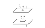
まず、フォトニック結晶バイオセンサー11について説明する。フォトニック結晶バイオセンサー11は、金属膜被覆フォトニック結晶21と、上部プレート22と、下部プレート23とを含む。上部プレート22は、開口部24が設けられている。本実施形態においては、フォトニック結晶バイオセンサー11は、上部プレート22と下部プレート23とにより金属膜被覆フォトニック結晶21を挟む構造である。なお、本実施形態においては、フォトニック結晶バイオセンサー11は、上部プレート22および下部プレート23を含んで形成されているが、これに限定されるものではなく、金属膜被覆フォトニック結晶21のみで形成されていてもよい。
まず、フォトニック結晶バイオセンサー11について説明する。フォトニック結晶バイオセンサー11は、金属膜被覆フォトニック結晶21と、上部プレート22と、下部プレート23とを含む。上部プレート22は、開口部24が設けられている。本実施形態においては、フォトニック結晶バイオセンサー11は、上部プレート22と下部プレート23とにより金属膜被覆フォトニック結晶21を挟む構造である。なお、本実施形態においては、フォトニック結晶バイオセンサー11は、上部プレート22および下部プレート23を含んで形成されているが、これに限定されるものではなく、金属膜被覆フォトニック結晶21のみで形成されていてもよい。
(金属膜被覆フォトニック結晶)
図2は、金属膜被覆フォトニック結晶21の斜視図である。図3は、金属膜被覆フォトニック結晶21の平面図である。図4は、図3におけるA-A断面を示す図であり、フォトニック結晶25の表面27と直交する平面でフォトニック結晶25を切ったときの断面を示す。後述する図5、図6も同様である。なお、図2~図6は、模式的に示した図であるため、金属膜被覆フォトニック結晶21を構成する成分の厚さ、大きさ等は実際とは異なる。以下、本実施形態及び後述する他の実施形態においても同様である。図2~図4に示すように、金属膜被覆フォトニック結晶21は、フォトニック結晶25および金属膜26を含んでいる。金属膜被覆フォトニック結晶21は、フォトニック結晶25の表面27に円柱状の凹部(以下、単に凹部という)28Aが周期的に形成された反射面29を金属膜26で被覆している。
図2は、金属膜被覆フォトニック結晶21の斜視図である。図3は、金属膜被覆フォトニック結晶21の平面図である。図4は、図3におけるA-A断面を示す図であり、フォトニック結晶25の表面27と直交する平面でフォトニック結晶25を切ったときの断面を示す。後述する図5、図6も同様である。なお、図2~図6は、模式的に示した図であるため、金属膜被覆フォトニック結晶21を構成する成分の厚さ、大きさ等は実際とは異なる。以下、本実施形態及び後述する他の実施形態においても同様である。図2~図4に示すように、金属膜被覆フォトニック結晶21は、フォトニック結晶25および金属膜26を含んでいる。金属膜被覆フォトニック結晶21は、フォトニック結晶25の表面27に円柱状の凹部(以下、単に凹部という)28Aが周期的に形成された反射面29を金属膜26で被覆している。
まず、フォトニック結晶25について説明する。フォトニック結晶は、表面に所定深さの凹部または所定高さの凸部が周期的に形成された反射面を有し、前記反射面に特定波長の光(平行光)を照射すると、その反射光が得られる構造体である。表面に凹部または凸部が周期的に形成された反射面に光を照射すると、特定波長の反射光が得られる構造体は、一般にフォトニック結晶と呼ばれる。
フォトニック結晶とは、サブ波長間隔の格子構造を有する構造体である。そして、それは構造体の表面(以後、反射面という)に広領域波長の光を照射すると、フォトニック結晶の表面状態に依存した特定の波長帯の光を、反射または透過するものである。フォトニック結晶の表面状態は、たとえばフォトニック結晶の形状及び材質に依存する。この反射光または透過光の変化を読み取ることにより、フォトニック結晶の表面状態の変化を定量化することができる。フォトニック結晶の表面状態の変化としては、表面への物質の吸着、構造変化などが挙げられる。表面に金属薄膜が形成されたフォトニック結晶も、光が照射されると、光の反射率または光の透過率に極値(極大値または極小値)が現れる。この反射率または透過率の極値は、金属の種類、金属の膜厚、フォトニック結晶の表面形状に依存するものである。この光の反射率または光の透過率を読み取ることにより、フォトニック結晶の表面状態の変化を定量化することができる。金属薄膜については後述する。フォトニック結晶の表面状態の変化を反射光または透過光の変化から定量化するには、次の方法を用いることができる。例えば、極値(極大値または極小値)での反射率または透過率の変化量、あるいは反射率または透過率が極値となる波長のシフト量を求めるなどである。なお、反射率または透過率の極値が複数ある場合には、任意の極値に着目する。そして、着目した極値について変化量を求めるか着目した極値となる波長のシフト量を求めることにより、フォトニック結晶の表面状態の変化を定量することができる。
図2~図4に示すように、フォトニック結晶25は、表面27に凹部28Aが周期的に形成された反射面29を有している。この反射面29に光を照射すると、フォトニック結晶25の形状と材質に依存した特定波長の光が反射される。
本実施形態において、凹部28Aは、三角形の格子状に配置されている。また、凹部28Aの直径D1は、50nm以上1000nm以下であることが好ましく、より好ましくは、100nm以上500nm以下である。また、凹部28Aの中心間の距離C1は、100nm以上2000nm以下であることが好ましく、より好ましくは、200nm以上1000nm以下である。また、凹部28Aの深さをH1としたとき、凹部28Aのアスペクト比(H1/D1)は、0.1以上10以下であることが好ましく、より好ましくは、0.5以上5.0以下である。なお、凹部28Aの寸法は、上記のものに限定されず、凹部28Aは、四角の格子、六角の格子などでもよい。凹部28Aは、三角形、四角、六角が組み合わされて格子状になっていてもよい。
フォトニック結晶25の形状及び寸法は、図2~図4に示した形状に限定されることはない。例えば、矩形または多角形の格子状のパターンが表面に形成されたもの、または平行線状パターンや波型形状パターンなどが表面に形成されたもの(詳しくは周期的にパターンなどが形成されたもの)、またはこれらのパターンの組合せであってもよい。
フォトニック結晶25の材質としては、合成樹脂などの有機材料、金属・セラミックなどの無機材料を使用することができる。
合成樹脂としては、ポリエチレン、ポリプロピレン、ポリメチルペンテン、ポリシクロオレフィン、ポリアミド、ポリイミド、アクリル、ポリメタクリル酸エステル、ポリカーボネート、ポリアセタール、ポリテトラフルオロエチレン、ポリブチレンテレフタレート、ポリエチレンテレフタレート、ポリ塩化ビニル、ポリ塩化ビニリデン、ポリスチレン、ポリフェニレンサルファイド、ポリエーテルサルフォン、ポリエーテルエーテルケトンなどの熱可塑性樹脂、フェノール樹脂、ユリア樹脂、エポキシ樹脂などの熱硬化性樹脂が使用することができる。
セラミックとしては、シリカ、アルミナ、ジルコニア、チタニア、イットリアなどのセラミックを好適に使用することができる。
金属としては、鉄鋼材料をはじめとして各種合金が使用可能である。具体的には、ステンレス鋼、チタンまたはチタン合金などを好適に使用することができる。
上記した各種材料の中でも、光学特性、加工性、標的物質(ターゲットとなる物質)を含有する溶液に対する耐性、標的物質捕捉物質(特異的結合物質)の吸着性、洗浄剤に対する耐性などを考慮すると、ポリシクロオレフィン系合成樹脂若しくはシリカ系のセラミックがより好ましい。この中でも、ポリシクロオレフィン系合成樹脂は、加工性に優れており最も好適である。
フォトニック結晶25は、上記材料基板の表面に微細な加工を施すことにより作製される。加工方法としては、レーザー加工、熱ナノインプリント、光ナノインプリント、フォトマスクとエッチングの組合せなどが使用できる。特に、ポリシクロオレフィン系合成樹脂などの熱可塑性樹脂を材料とする場合には、熱ナノインプリントによる方法が好適である。
次に、金属膜26について説明する。本実施形態において、図4に示すように、フォトニック結晶25は、その反射面29が金属膜26で被覆されている。金属膜26は、金(Au)、銀(Ag)、白金(Pt)またはアルミニウム(Al)のうちの何れか1種類以上を用いて形成されることが好ましい。本実施形態において、金属膜26はAuで形成されている。Auは、安定性に優れるため、反射面29として好ましい。金属膜26に銀(Ag)またはアルミニウム(Al)のうちの何れか1種類以上を用いる場合、金で表面を被覆することが好ましい。このようにすることで、金の使用量を低減してフォトニック結晶25の製造コストを抑制することができる。
金属膜26の膜厚が小さいと、フォトニック結晶25への入射光の一部は金属膜26を透過することがある。その結果、反射光から得られる情報量の低下、回折光またはフォトニック結晶25の裏面からの反射光など、フォトニック結晶25からの反射光には不要な情報が多く含まれる可能性がある。金属膜26の膜厚を適度に大きくすることにより、フォトニック結晶25からの反射光に含まれる不要な情報を低減して、標的物質の検出精度及び濃度の計測精度を向上させることができる。また、金属膜26の膜厚が適度に小さいと、フォトニック結晶25の表面27に詳細なパターン形状を作製することが容易であるので好ましい。例えば、パターンの角がシャープになって、パターンの寸法を確保することが容易となる。このような観点から、本実施形態において、金属膜26の膜厚は、好ましくは30nm以上1000nm以下であり、より好ましくは150nm以上500nm以下であり、さらに好ましくは200nm以上400nm以下である。波長に対する反射率の変化は、金属膜26の膜厚が200nmを超えるとほぼ同様になるためである。
また、金属膜26は、スパッタリングまたは蒸着装置などによってフォトニック結晶25の反射面29に形成することができる。金属膜26の最表面は、Auとすることが好ましい。金属膜26にAg、Pt、Alを用いた場合、それぞれの極値における反射光の波長は、Auを金属膜26として用いた場合に対して1.5倍となる。このように、Ag、Pt、Alは、Auよりも1.5倍の感度を有する。なお、Agは酸化されやすいので、フォトニック結晶25の反射面29にAgを形成した後、酸化されにくいAuまたはSiO2などの酸化物薄膜を形成することが好ましい。この場合、200nmの厚さを有するAgの膜の表面に、5nmの厚さを有するAuの膜を形成することができる。200nmの厚さを有するAgの膜の表面に5nmの厚さを有するAuの膜を形成した場合、200nmの厚さを有するAuの膜に比べて、感度が1.5倍になる。また、5nmのAuの膜の有無で、感度の変化は見られなかった。AlもAgと同様に酸化されやすいので、フォトニック結晶25の表面27にAlの膜を形成した後、酸化されにくいAuまたはSiO2などの酸化物薄膜を形成することが好ましい。抗体などで修飾するために、Ptも、AuまたはSiO2などの酸化物薄膜を形成することが好ましい。
また、フォトニック結晶25の反射面29は、3-triethoxysilylpropylamine(APTES)などを用いて改質されることが好ましい。フォトニック結晶25の反射面29に、AuまたはAgの金属膜26を形成させた場合には、APTESではなく、一端にチオール基を有し、他端にアミノ基やカルボキシル基などの官能基を有する炭素鎖を用いてフォトニック結晶25の反射面29を改質することが好ましい。AuまたはAg以外の金属膜26をフォトニック結晶25の反射面29に形成させた場合は、一端に官能基を有するシラン系カップリング剤、例えばAPTESを使用して、フォトニック結晶25の反射面29を改質することが好ましい。
金属膜被覆フォトニック結晶21は、フォトニック結晶25の反射面29を金属膜26で被覆したものであるため、フォトニック結晶25の凹部28Aに対応して反射面29に金属膜被覆フォトニック結晶21の凹部28Bが周期的に形成されている。凹部28Bは、凹部28Aと同様、三角形の格子状に配置されている。また、凹部28Bの直径D2は、金属膜26の厚さにもよるが、50nm以上1000nm以下であることが好ましく、より好ましくは、100nm以上500nm以下である。また、凹部28Bの中心間の距離C2は、凹部28Aの中心間の距離C1と同様、100nm以上2000nm以下であることが好ましく、より好ましくは、200nm以上1000nm以下である。また、凹部28Bの深さをH2としたとき、凹部28Bのアスペクト比(H2/D2)は、0.1以上10以下であることが好ましく、より好ましくは、0.5以上5.0以下である。なお、凹部28Bの寸法は、上記のものに限定されない。
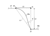
凹部28Bは、凹部28Bの壁面28aが凹部28Bの底面28bに所定の角度を有して形成されている。図5は、凹部28Bの壁面28aの部分拡大図である。また、後述する図6も同様である。なお、図5では、説明の便宜上、フォトニック結晶25の表面27に設けられる金属膜26は省略する。図5に示すように、凹部28Bの壁面28aは、凹部28Bの平坦となる底面28bに所定の角度を有している。凹部28Bの底面28bの重心を通る断面において、凹部28Bの壁面28aと底面28bとの境界を第1境界部31とする。表面27と凹部28Bの壁面28aとの境界を第2境界部32とする。底面28bに対して垂直方向に第1境界部31を通る直線と、底面28bに対して水平方向に第2境界部32を通る直線との交点を交点Aとする。第1境界部31と第2境界部32とを直線で結ぶ距離をL1とする。第1境界部31と交点Aとを直線で結ぶ距離をL2とする。第2境界部32と交点Aとを直線で結ぶ距離をL3とする。L1とL2とが成す角度をθとする。このとき、凹部28Bは、下記式(1)、(2)を満たすようにL1とL2とが成す角度θが形成されている。
tanθ=L3/L2 ・・・(1)
0≦tanθ≦1.0 ・・・(2)
tanθ=L3/L2 ・・・(1)
0≦tanθ≦1.0 ・・・(2)
凹状の穴(ホール)が周期的に配列して設けられた構造を有する金属の表面に光を照射したとき、反射光の波長スペクトルにピークが観察される。反射光の波長に対する反射率が最大となる波長(ピーク波長)は、一般的に下記式(i)で求めることができる。式(i)中、λpeakは、ピーク波長であり、a0は、ホールの周期であり、i、jは、回折次数であり、εmは、金属の誘電率であり、εdは、環境の誘電率である。

上記式(i)によれば、凹部28Bが配置される周期を与えられればピーク波長が求まる。ピーク波長のスペクトルを観察する場合、ピーク波長のスペクトルの幅が小さい方が容易にピーク波長の位置を特定することができる。よって、凹部28Bの配置される周期が明確に与えられることで、ピーク波長のスペクトルの幅は小さくなり、ピーク波長の位置が特定し易くなる。
金属膜被覆フォトニック結晶21は、凹部28Bが反射面29に周期的に形成された周期構造を有するものである。凹部28Bの壁面28aが、上記式(1)、(2)を満たすように反射面29に形成されることにより、反射光の波長スペクトルの形状は幅が狭くなり、反射光のピーク波長を容易に特定することができる。これにより、標的物質を精度よく検出することができる。この結果、フォトニック結晶バイオセンサー11のセンサ感度を高めることができる。なお、反射光の波長スペクトルの形状の幅は、半値幅などである。
また、凹部28Bは、下記式(2)’を満たすように形成されていることが好ましい。凹部28Bの壁面28aが、上記式(1)、下記式(2)’を満たすように形成されることにより、反射光の波長スペクトルの形状は更に幅が狭くなり、反射光のピーク波長を更に容易に特定することができる。この結果、標的物質を更に精度よく検出することができる。
0≦tanθ≦0.7・・・(2)’
0≦tanθ≦0.7・・・(2)’
式(2)及び(2)’から、θは0度以上となる。θ=0度である場合、金属被膜フォトニック結晶21の表面27と凹部28Bの壁面28aとの接続部分Kが略90度になる。接続部分Kが略90度になると、金属膜被覆フォトニック結晶21の形状の制御、特に凹部28Bの形状の制御が難しくなる。すなわち、凹部28Bの所期の形状を得ることが難しくなる。tanθ>0、すなわちθを0よりも大きくすることにより、特に凹部28Bの所期の形状を得やすくなるので好ましい。例えば、フォトニック結晶25を射出成形型またはインプリント等で作る場合は、抜き勾配も確保できるため、好ましい。また、金属膜被覆フォトニック結晶21は、比較的圧力の高い水で洗浄されるが、接続部分Kの角度が略90度になると、角が取れやすくなる。その結果、凹部28Bは所期の形状を有さなくなる可能性がある。tanθ>0、すなわちθを0よりも大きくすることにより、接続部分Kの角が取れる可能性を低減できるので、凹部28Bは、洗浄後においても所期の形状を有するようになるので好ましい。さらに、tanθ>0、すなわちθを0よりも大きくすることにより、凹部28B内に水が入りやすくなるので、標的物質を確実に凹部29Bに捕捉することができる。
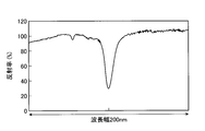
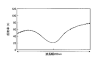
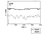
図5に示す金属膜被覆フォトニック結晶21を用いて波長スペクトルを測定した結果を実施例1とする。図6は、金属膜被覆フォトニック結晶21の他の凹部28Bの壁面28aの部分拡大図である。図6に示す金属膜被覆フォトニック結晶21を用いて波長スペクトルを測定した結果を実施例2とする。図7は、実施例1の反射光の波長に対する反射率を示す図である。図8は、実施例2の反射光の波長に対する反射率を示す図である。図9は、実施例1および実施例2の時間とピーク波長との関係を示す図である。なお、実施例1では、tanθを約0.31とし、実施例2では、tanθを約0.71とした。また、図6中、第1境界部31と第2境界部32とを直線で結ぶ距離をL1とする。第1境界部31と交点Aとを直線で結ぶ距離をL2とする。第2境界部32と交点Aとを直線で結ぶ距離をL3とする。また、図7、図8中、波長幅は、200nmとした。図7~図9中、照射する光は白色光を用いた。反射率は、標準物質(アルミニウム板)の反射光強度に対する比率である。
図7、図8に示すように、実施例1の方が実施例2よりもピーク波長の形状は幅が狭く、反射光のピーク波長を容易に特定することができる。また、図9に示すように、実施例1の方が実施例2よりもピーク波長の波長幅のぶれは小さく、ノイズが少ない。よって、実施例2のように、tanθが大きいと、反射面29における凹部28Bの周期が不明瞭となり易くなるため、ピーク波長のスペクトルの幅が大きくなり、ピーク波長の位置が特定し難くなると共に、ノイズの発生源となりやすいことがいえる。これに対し、実施例1のように、tanθが小さいと、反射面29における凹部28Bの周期がより明確となるため、ピーク波長のスペクトルの幅が小さくなり、ピーク波長の位置が特定し易くなると共に、ノイズを減少することができるといえる。このことから、反射光の波長スペクトルの形状の幅が狭く、反射光のピーク波長を容易に特定することができるようにするためには、反射面29の表面27における凹部28Bの周期が明確であることが重要であるといえる。そして、凹部28Bの周期を明確にすることは、凹部28Bの壁面28aが底面28bに対して形成される角度に依存するといえる。
金属膜被覆フォトニック結晶21の表面は、凹部28Bの壁面28aが上記式(1)、(2)を満たすように形成されている。そのため、金属膜被覆フォトニック結晶21の反射面29に光を照射すると、反射光の波長スペクトルの形状は幅が狭くなり、反射光のピーク波長を容易に特定することができる。これにより、標的物質を精度よく検出することができ、フォトニック結晶バイオセンサー11のセンサ感度を高めることができる。
(フォトニック結晶の作製方法)
次に、熱ナノインプリントにより金属膜被覆フォトニック結晶21を作製する工程の一例を説明する。図10、図11及び図12は、フォトニック結晶の作製方法を説明する図である。図10に示すように、熱ナノインプリントでは、ナノメートルレベルの微細構造、またはナノメートルレベルの周期構造のパターンを有する金型DIを用いる。そして、図11に示すように、加熱した金型DIをシート状の樹脂Pに押し付けて、所定圧力で所定時間押圧し、金型DIの表面温度が所定温度になったところで離型し、微細構造及び周期構造をシート状の樹脂Pに転写する。これにより、フォトニック結晶25が得られる。
次に、熱ナノインプリントにより金属膜被覆フォトニック結晶21を作製する工程の一例を説明する。図10、図11及び図12は、フォトニック結晶の作製方法を説明する図である。図10に示すように、熱ナノインプリントでは、ナノメートルレベルの微細構造、またはナノメートルレベルの周期構造のパターンを有する金型DIを用いる。そして、図11に示すように、加熱した金型DIをシート状の樹脂Pに押し付けて、所定圧力で所定時間押圧し、金型DIの表面温度が所定温度になったところで離型し、微細構造及び周期構造をシート状の樹脂Pに転写する。これにより、フォトニック結晶25が得られる。
樹脂Pがシクロオレフィン系ポリマーの場合には、金型DIを160℃程度まで加熱し、約12MPaの圧力で所定時間押圧し、金型DIの表面温度が60℃程度になったところで離型することが好ましい。
フォトニック結晶25を作製した後、図12に示すように、金型DIと接していた表面に、スパッタリングまたは蒸着装置などによって金属膜26を形成して、金属膜被覆フォトニック結晶21が完成する。
(標的物質捕捉物質)
次に、標的物質を捕捉する標的物質捕捉物質について説明する。標的物質とは、標的物質検出装置10が検出する対象物であって、タンパク質などの高分子、オリゴマー、低分子のいずれであってもよい。標的物質は、単分子に限定されず、複数の分子からなる複合体であってもよい。標的物質として、例えば、大気中の汚染物質、水中の有害物質、人体内のバイオマーカー(Biomarker)などが挙げられる。中でも、コルチゾールなどが好ましい。コルチゾールは、分子量362g/molの低分子物質である。コルチゾールは、人間がストレスを感じると唾液中のコルチゾール濃度が増加するため、人間が感じているストレスの度合いを評価する物質として注目されている。コルチゾールを標的物質としてその濃度を測定すれば、例えば、ヒトの唾液中に含まれるコルチゾールの濃度を測定することで、ストレスの度合いを評価することができる。ストレスの度合いを評価すれば、被測定者がうつ病などの精神疾患につながるレベルのストレス状態にあるか否かを判断することができる。
次に、標的物質を捕捉する標的物質捕捉物質について説明する。標的物質とは、標的物質検出装置10が検出する対象物であって、タンパク質などの高分子、オリゴマー、低分子のいずれであってもよい。標的物質は、単分子に限定されず、複数の分子からなる複合体であってもよい。標的物質として、例えば、大気中の汚染物質、水中の有害物質、人体内のバイオマーカー(Biomarker)などが挙げられる。中でも、コルチゾールなどが好ましい。コルチゾールは、分子量362g/molの低分子物質である。コルチゾールは、人間がストレスを感じると唾液中のコルチゾール濃度が増加するため、人間が感じているストレスの度合いを評価する物質として注目されている。コルチゾールを標的物質としてその濃度を測定すれば、例えば、ヒトの唾液中に含まれるコルチゾールの濃度を測定することで、ストレスの度合いを評価することができる。ストレスの度合いを評価すれば、被測定者がうつ病などの精神疾患につながるレベルのストレス状態にあるか否かを判断することができる。
標的物質捕捉物質とは、標的物質と結合し、標的物質を捕捉する物質である。ここで、結合するとは、化学的に結合する場合の他、例えば物理吸着、ファンデルワールス力による結合のように、化学的結合によらない結合であってもよい。好ましくは、標的物質捕捉物質は、標的物質と特異的に反応して標的物質を捕捉するものであり、標的物質を抗原とした抗体であることが好ましい。特異的に反応するとは、選択的に標的物質と可逆的または不可逆的な結合をして複合体を形成することを意味し、化学反応に限定されない。また、特異的に反応する物質が標的物質以外に存在していても構わない。試料中に標的物質の他に標的物質捕捉物質と反応する物質があっても、その親和性が標的物質と比較して非常に小さい場合は、標的物質を定量することができる。標的物質捕捉物質は、標的物質を抗原とした抗体、人工的に作製した抗体、アデニン、チミン、グアニン、シトシンなどのDNAを構成する物質から構成される分子、ペプチドなどを用いることができる。標的物質がコルチゾールである場合は、標的物質捕捉物質は、コルチゾール抗体であることが好ましい。
標的物質捕捉物質を作製するには公知の方法を採用することができる。例えば、抗体は、血清法、ハイブリドーマ法、ファージディスプレイ法によって作製できる。DNAを構成する物質から構成される分子は、例えばSELEX法(Systematic Evolution of Ligands by Exponential Enrichment:試験管内人工進化法)により作製できる。ペプチドは、例えばファージディスプレイ法により作製できる。標的物質捕捉物質は、何らかの酵素・同位体により標識されている必要はない。しかし、酵素・同位体によって標識されていてもよい。
本実施形態において、標的物質捕捉物質は、図4に示す金属膜被覆フォトニック結晶21の反射面29に固定される。標的物質捕捉物質を金属膜被覆フォトニック結晶21の反射面29に固定する手段として、共有結合、化学吸着、物理吸着などの化学的結合、物理的結合方法が挙げられる。これらの手段を、標的物質捕捉物質の性質に応じて適宜選択することができる。例えば、固定する手段として吸着を選択した場合、吸着の操作は以下のようなものである。例えば、標的物質捕捉物質を含んだ溶液を、金属膜被覆フォトニック結晶21の反射面29に滴下し、金属膜被覆フォトニック結晶21を、所定の時間、室温で、または必要に応じて冷却・加温して、標的物質捕捉物質を反射面29に吸着させる。
フォトニック結晶バイオセンサー11は、特定の抗原(例えばコルチゾール)とのみ結合する抗体(例えばコルチゾール抗体)を金属膜被覆フォトニック結晶21の反射面29の表面に予め吸着(固定)させておく。これにより、フォトニック結晶バイオセンサー11は、特定の抗原を検出することができる。これは、フォトニック結晶25の光学的特性と、フォトニック結晶25の表面または表面近傍で起こる各種の生体・化学反応、例えば特定の抗原は特定の抗体とのみ反応するという抗原抗体反応とを利用するものである。
フォトニック結晶バイオセンサー11は、標的物質捕捉物質である抗体が固定された反射面29に、ブロッキング剤(保護物質)が固定されたものであってもよい。ブロッキング剤は、標的物質がフォトニック結晶バイオセンサー11に接触させられる前に固定される。フォトニック結晶25の反射面29の表面は、一般的に超疎水性である。このため、疎水性相互作用によって標的物質捕捉物質である抗体以外の不純物が、反射面29に吸着してしまうおそれがある。さらに、フォトニック結晶25の光学特性は表面状態に大きく影響されるので、フォトニック結晶25の反射面29には、不純物が吸着されていないことが好ましい。フォトニック結晶25の反射面29にブロッキング剤が固定されることで、反射光の検出精度を向上させることができる。
したがって、標的物質捕捉物質である抗体がフォトニック結晶25の反射面29に吸着(固定)された部分以外の箇所には、不純物などが固定されないように、いわゆるブロッキング剤を予め固定させておくことが好ましい。ブロッキング剤を予め吸着させておくには、ブロッキング剤を、フォトニック結晶25の表面に接触させる。ブロッキング剤として、スキムミルクやウシ血清アルブミン(BSA)などを使用することができる。
次に、フォトニック結晶バイオセンサー11が標的物質である抗原及びその濃度を検出する基本的な原理を説明する。図13~図16は、フォトニック結晶バイオセンサー11の原理を説明する図である。一般的に、フォトニック結晶バイオセンサー11は、フォトニック結晶25の光学的特性と、フォトニック結晶25の表面または表面近傍で起こる各種生体・化学反応、例えば、特定の抗原は特定の抗体とのみ反応するという抗原抗体反応とを利用して、微量のタンパク質または低分子物質を検出するものである。そして、フォトニック結晶バイオセンサー11は、金属膜被覆フォトニック結晶21の反射面29に特定波長の光を照射したときの表面プラズモン共鳴現象及び/または局在表面プラズモン共鳴現象による反射光の波長の極値がシフトする現象を利用する。
図13に示すように、金属膜被覆フォトニック結晶21の反射面29の表面には、抗体(標的物質捕捉物質)34が吸着により固定されている。
次に、図14に示すように、反射面29の抗体34が吸着した部分以外の箇所、すなわち、抗体34が吸着した部分以外の反射面29に、ブロッキング剤(保護物質)35を予め吸着させる。これにより、反射面29の抗体34が吸着した部分以外の箇所に不純物などが吸着しないようにする。
次に、図15に示すように、抗体34とブロッキング剤35とが吸着されているフォトニック結晶バイオセンサー11に抗原(標的物質)36を接触させ、抗原抗体反応を行う。抗体34に抗原36が捕捉された複合体37が、反射面29に固定される。
次に、図1に示す光検出部12は、図16に示すように、抗原36がフォトニック結晶25の反射面29に捕捉されている状態で特定波長の光(入射光)LIを平行光で金属膜被覆フォトニック結晶21の反射面29に照射する。そして、図1に示す光検出部12は、反射面29で反射された反射光LRを検出し、反射光LRの極値の波長を求める。そして、図1に示す処理部13は、反射光LRの強度の極値における波長及び強度の極値における波長のシフト量を求めて、金属膜被覆フォトニック結晶21の反射面29に捕捉された抗原36の有無を検出したり、抗原36の濃度を求めたりする。
フォトニック結晶バイオセンサー11は、上記原理に基づき、抗体34および抗原36の組合せの種類を変えることにより、検出対象の物質であるタンパク質などの各種生体物質または低分子量物質の種類を変えることができる。
フォトニック結晶バイオセンサー11では、反射面29に固定された抗体34に抗原36が捕捉されることにより、反射面29の状態が変化し、反射光LRに変化が生じる。フォトニック結晶バイオセンサー11は、光学的な物理量を出力する。この物理量は、金属膜被覆フォトニック結晶21の反射面29における表面状態の変化に相関し、反射面29に固定された抗体34に抗原36が捕捉されて形成される複合体37の量と相関する。光学的な物理量は、例えば、反射光LRの強度が極値となる波長のシフト量、光の反射率の変化量、光の反射率が極値となる波長のシフト量、反射光LRの強度、反射光LRの強度の極値の変化量などである。本実施形態では、反射光LRの強度または光の反射率が極値となる波長のシフト量を用いる。
光学的な物理量を出力させるには、例えば以下のようにして行う。金属膜被覆フォトニック結晶21の反射面29に対して垂直に光を入射し、反射光LRを検出する。金属膜被覆フォトニック結晶21の反射面29の垂線に対して角度をつけて光を入射し、反射光LRを検出することもできる。反射光LRを検出することにより、図1に示す標的物質検出装置10をコンパクトにすることができる。垂直に入射され、垂直に反射された光を検出する場合には、二股の光ファイバーを用いて光を入射し、反射光LRを検出することが好ましい。この構造については後述する。
(フォトニック結晶バイオセンサーの作製方法)
次に、図1に示すフォトニック結晶バイオセンサー11の作製の一例について説明する。図17、図18及び図19は、フォトニック結晶バイオセンサー11の説明図である。図17に示すように、金属膜被覆フォトニック結晶21を下部プレート23に設置した後、図18に示すように、上部プレート22を下部プレート23の上に設置して、金属膜被覆フォトニック結晶21を、下部プレート23と上部プレート22とにより挟むことにより、フォトニック結晶バイオセンサー11が作製される。開口部24の下部プレート23側における端部は、フォトニック結晶25の反射面29により閉塞される。このような構造により、上部プレート22は、開口部24側の内壁と反射面29とで囲まれて形成される、一定容積の液滴保持部38を有する。開口部24側の内壁とは、上部プレート22と開口部24との境界面である、上部プレート22の内壁をいう。
次に、図1に示すフォトニック結晶バイオセンサー11の作製の一例について説明する。図17、図18及び図19は、フォトニック結晶バイオセンサー11の説明図である。図17に示すように、金属膜被覆フォトニック結晶21を下部プレート23に設置した後、図18に示すように、上部プレート22を下部プレート23の上に設置して、金属膜被覆フォトニック結晶21を、下部プレート23と上部プレート22とにより挟むことにより、フォトニック結晶バイオセンサー11が作製される。開口部24の下部プレート23側における端部は、フォトニック結晶25の反射面29により閉塞される。このような構造により、上部プレート22は、開口部24側の内壁と反射面29とで囲まれて形成される、一定容積の液滴保持部38を有する。開口部24側の内壁とは、上部プレート22と開口部24との境界面である、上部プレート22の内壁をいう。
図19は、液滴保持部38に所定の溶液を滴下した状態を示す。この場合、液滴保持部38が液滴保持機能を発揮するため、開口部24から溶液が流出するのを抑制する。また、溶液の量としては、液滴保持部38に広がる程度の量があれば、標的物質の十分な検出・測定が可能となる。
開口部24の形状は、円柱形に限らず、開口部24の内部に液滴を保持することができれば、他の形状としてもよい。また、開口部24を円柱状とした場合、その直径などは、抗体34及び抗原36の組合せの種類、必要な測定精度または反射光の検出器の光学系に合わせて様々な直径とすることができる。開口部24の直径は、上述した抗体34に抗原36を吸着させる際の操作、取扱いの利便性などを考慮し、0.5mm~10mmであることが好ましく、より好ましくは、2mm~6mmである。
上部プレート22および下部プレート23の材質などは、特に限定されない。ただし、上部プレート22および下部プレート23の表面の清浄度などを考慮すると、ステンレス鋼、ポリシクロオレフィン系樹脂、シリカなどを用いて形成されることが好ましい。
次に、フォトニック結晶バイオセンサー11の別の形態について説明する。上部プレート22は、疎水性の材料で形成してもよい。特に、唾液などのいわゆる親水性の溶液の検出・測定を行う場合に、上部プレート22が疎水性の材料で形成されていれば、液滴保持部38に的確に溶液を集めることができる。また、脂質などのいわゆる親油性の溶液の検出・測定を行う場合、上部プレート22が疎水性の材料で形成されていれば、液滴保持部38に的確に溶液を集めることができる。
さらに、上部プレート22は、撥水性若しくは撥油性または撥水撥油性のある材料で形成してもよい。すなわち、疎水性、親油性、親水性、撥水性、撥油性を発揮する表面処理またはコーティングを溶液の性質に合わせて上部プレート22に施してもよい。このようにすることで、液滴保持部38に的確に溶液を集めることができる。
フォトニック結晶バイオセンサー11は、フォトニック結晶バイオセンサー11の下部に、図1に示す光検出部12に対してフォトニック結晶バイオセンサー11の位置を定めて、フォトニック結晶バイオセンサー11を固定するための固定材(標的物質捕捉部固定手段、フォトニック結晶バイオセンサー固定手段)を装着することが好ましい。固定材としては、マグネットシート、両面テープ、接着剤などが使用できる。また、フォトニック結晶バイオセンサー11を固定するために、固定材ではなく、固定機構として真空チャックまたは静電チャックを用いてもよい。フォトニック結晶バイオセンサー11を固定しておくことにより、検出・測定時の振動などによる測定位置のずれを減少することが可能となる。その結果、より正確な検出・測定ができる。
図20、図21は、フォトニック結晶バイオセンサー固定手段を説明する図である。図20は、マグネットシート39の取付け前の状態を示し、図21は、マグネットシート39の取付け後の状態を示す。フォトニック結晶バイオセンサー11は、フォトニック結晶バイオセンサー11の下部側にマグネットシート39が取り付けられている。マグネットシート39は、フォトニック結晶バイオセンサー固定手段として機能する。
フォトニック結晶バイオセンサー11は、熱ナノインプリントなどにより均一に作製されている。標的物質検出装置10がより正確に反射光の検出ができるようにするため、フォトニック結晶バイオセンサー11に照射される光の入射部位、反射部位を正確に位置決めすることが好ましい。
すなわち、フォトニック結晶バイオセンサー11と後で説明する測定プローブとの測定時の位置関係は、抗原抗体反応の前後で同一であることが好ましく、同一の部分を測定することが好ましい。したがって、測定プローブとフォトニック結晶バイオセンサー11の反射面29との距離は、抗原抗体反応の前後で同一であることが好ましく、50μm~500μmに固定することが好ましい。フォトニック結晶バイオセンサー11は、上部プレート22を含むことで、上部プレート22がスペーサとして機能し、測定プローブとフォトニック結晶バイオセンサー11の反射面29との距離を一定にすることができる。
また、フォトニック結晶バイオセンサー11に、反射面29における特定の位置を表示する、位置決め用のマーカーによってマークを付けるようにしてもよい。マーカーは、フォトリソグラフィー、スパッタリング、蒸着、これらを利用したリフトオフプロセス、インクなどによる印刷またはインプリントによるパターン形成などによって付けることができる。マーカーは、その位置を読み取ることができればフォトニック結晶バイオセンサー11の表面(反射面29側)または裏面(反射面29の反対側)のどちらに付けてもよい。また、フォトニック結晶25の測定部分を外してフォトニック結晶25自体にマーカーを付けてもよい。さらに、マーカーを上部プレート22、下部プレート23に付けてもよい。
次に、フォトニック結晶バイオセンサー11の更に別の形態について説明する。図22は、フォトニック結晶バイオセンサー11の別の形態を説明する図である。図22に示すように、フォトニック結晶バイオセンサー11は、開口部24を塞ぐ部材を含む。開口部24を塞ぐ部材は、孔付カバー41とシート42とを含む。孔付カバー41は、開口部43を有する板状部材であり、孔付カバー41は、フォトニック結晶バイオセンサー11の表面(反射面29側)に設けられる。シート42は、孔付カバー41のフォトニック結晶バイオセンサー11とは反対側(光の入射側)に設けられる。シート42は、被覆部材として機能する。フォトニック結晶バイオセンサー11は、孔付カバー41とシート42とにより開口部24、43が塞がれる。
孔付カバー41の開口部43側の内壁と、開口部24側の内壁と、フォトニック結晶25の反射面29とで囲まれた空間が、一定容積の液滴保持部44となる。開口部43側の内壁とは、孔付カバー41と開口部43との境界面である、孔付カバー41の内壁をいう。開口部43は、液滴保持部44に標的物質が配置された後、シート42により覆われる。これにより、液滴保持部44はシート42により塞がれる。
フォトニック結晶バイオセンサー11は、孔付カバー41及びシート42を備えることで、フォトニック結晶バイオセンサー11の開口部24に滴下された溶液の蒸発を抑制することができる。このため、抗原抗体反応時の蒸発などによる溶液の濃度が変化するのを抑制することができる。また、フォトニック結晶バイオセンサー11は、孔付カバー41及びシート42を備えることで、外部から溶液へ異物が混入することを防止することができる。
さらに、液滴保持部44に溶液を充填することにより、溶液を充填した状態で反射光の測定をより正確に行うことも可能である。この場合、シート42は透明な材料であることが好ましく、より好ましくは、反射光の強度の極値における波長の光の吸収が少ないものが好ましい。例えば、シート42の材料は、可視光線領域から紫外線領域の反射光で測定する場合は石英(シリカ)などが好ましい。
[光検出部12]
次に、図1に示す光検出部12について説明する。図1に示す光検出部12は、光源51と、測定プローブ52と、光検出装置53と、第1光ファイバー54と、第2光ファイバー55と、コリメートレンズ56とを含む。光源51と測定プローブ52とは、第1光ファイバー54により光学的に接続されている。測定プローブ52と光検出装置53とは、第2光ファイバー55により光学的に接続されている。必要に応じて、光源51及び光検出装置53などに接続され、光源51の制御及び光検出装置53からの信号を処理する制御装置を設けてもよい。
次に、図1に示す光検出部12について説明する。図1に示す光検出部12は、光源51と、測定プローブ52と、光検出装置53と、第1光ファイバー54と、第2光ファイバー55と、コリメートレンズ56とを含む。光源51と測定プローブ52とは、第1光ファイバー54により光学的に接続されている。測定プローブ52と光検出装置53とは、第2光ファイバー55により光学的に接続されている。必要に応じて、光源51及び光検出装置53などに接続され、光源51の制御及び光検出装置53からの信号を処理する制御装置を設けてもよい。
図23は、光検出部12がフォトニック結晶バイオセンサー11に光を照射する例を示す図である。図1に示す第1光ファイバー54は、図1に示す光源51からの光を測定プローブ52に導き、測定プローブ52からフォトニック結晶バイオセンサー11が有する金属膜被覆フォトニック結晶21の反射面29へ照射する。コリメートレンズ56は、第1光ファイバー54から出射し、測定プローブ52から照射された光を平行光にしてから、フォトニック結晶25の反射面29へ入射光LIとして照射する。第2光ファイバー55は、金属膜被覆フォトニック結晶21の反射面29で反射した光を反射光LRとして受光し、図1に示す光検出装置53へ導く。コリメートレンズ56の種類は特に限定されないが、例えば、ナノストラクチャーを持つ反射防止フィルムを用いることができる。光検出装置53は、例えば、フォトトランジスタまたはCCD(Charge Coupled Device)などの受光素子を備えた、光を検出するための装置である。
図24は、図1に示す光検出部12が有する測定プローブ52の構造を示す図である。測定プローブ52は、第1光ファイバー54と第2光ファイバー55とが接合される。そして、測定プローブ52は、第1光ファイバー54の光の出射面61と、第2光ファイバー55の反射光LRの入射面62とが同一の面(入出射面)63上に配置される。このように、測定プローブ52は、第1光ファイバー54と第2光ファイバー55とが、第1光ファイバー54の出射側(出射面61側)と第2光ファイバー55の入射側(入射面62側)とで一体となっている。そして、測定プローブ52は、第1光ファイバー54と第2光ファイバー55とを用いて光を入射し、反射光LRを検出する。
測定プローブ52は、このような構造としているため、フォトニック結晶25の反射面29に照射する入射光LIと、反射面29からの反射光LRとをほぼ同一の位置から出射し、入射させることができる。測定プローブ52を上述したような構造にするとともに、コリメートレンズ56を用いて測定プローブ52からの光を平行光にすることで、光検出部12は、反射面29に平行光の入射光LIを垂直に入射することができる。それとともに、反射面29から垂直に反射した反射光LRを受光することができる。このようにすることで、測定プローブ52は、反射光強度の低下を最小限に抑えることができるとともに、主として反射光LRの0次光成分を検出することができる。これにより、処理部13は、金属膜被覆フォトニック結晶21の反射面29の正確な情報を得ることができるため、標的物質の検出精度及び濃度の計測精度が向上する。なお、反射光LRを検出する手法は、上述したような測定プローブ52に限定されない。例えば、コリメートレンズ56と反射面29との間にハーフミラーを配置し、ハーフミラーによって反射光LRを分離して第2光ファイバー55から光検出装置53に導いてもよい。
次に、光検出部12の評価条件を説明する。図25は、本実施形態に係る標的物質検出装置10の光検出部12の評価条件を示す図である。図25に示すように、光検出部12は、測定プローブ52の入出射面63と金属膜被覆フォトニック結晶21の反射面29との間にコリメートレンズ56を配置する。コリメートレンズ56と反射面29との距離(計測距離)をh、コリメートレンズ56から出射した平行光の反射面29における直径をd1、フォトニック結晶25の反射面29が露出する開口部24の直径をd2とする。本評価では、hを15mmまたは40mmとし、d1を3.5mm、d2を5mmとした。反射面29に照射される光の光軸ZL及び反射面29で反射された反射光の光軸ZLは、いずれも反射面29に対して直交している。測定プローブ52の直径は200μmである。照射する光は白色光を用いた。反射率は、標準物質(アルミニウム板)の反射光強度に対する比率である。
[処理部13]
次に、図1に示す処理部13について説明する。処理部13は、光検出部12が検出した反射光の極値の波長を求める。処理部13は、それとともに、求めた極値の波長のシフト(波長シフト量)に基づいて、少なくとも標的物質(例えば、図15、図16などに示す抗原36)の有無を検出する。処理部13は、例えば、マイクロコンピュータである。波長シフト量と金属膜被覆フォトニック結晶21の反射面29に捕捉された標的物質の濃度とは相関がある。このため、処理部13は、波長シフト量から反射面29に捕捉された標的物質の濃度を求めることができる。
次に、図1に示す処理部13について説明する。処理部13は、光検出部12が検出した反射光の極値の波長を求める。処理部13は、それとともに、求めた極値の波長のシフト(波長シフト量)に基づいて、少なくとも標的物質(例えば、図15、図16などに示す抗原36)の有無を検出する。処理部13は、例えば、マイクロコンピュータである。波長シフト量と金属膜被覆フォトニック結晶21の反射面29に捕捉された標的物質の濃度とは相関がある。このため、処理部13は、波長シフト量から反射面29に捕捉された標的物質の濃度を求めることができる。
(標的物質を検出する方法)
次に、図1に示す標的物質検出装置10を用いて標的物質を検出する方法(標的物質検出方法)を説明する。この例においては、金属膜被覆フォトニック結晶21の反射面29にコルチゾール抗体を吸着させて、唾液中のコルチゾールを検出対象の標的物質として、検出・測定する場合を説明する。フォトニック結晶25としては、熱ナノインプリントにより所定の微細構造を表面に形成したシクロオレフィン系ポリマーのシートを所定の大きさに切断したものを用いている。
次に、図1に示す標的物質検出装置10を用いて標的物質を検出する方法(標的物質検出方法)を説明する。この例においては、金属膜被覆フォトニック結晶21の反射面29にコルチゾール抗体を吸着させて、唾液中のコルチゾールを検出対象の標的物質として、検出・測定する場合を説明する。フォトニック結晶25としては、熱ナノインプリントにより所定の微細構造を表面に形成したシクロオレフィン系ポリマーのシートを所定の大きさに切断したものを用いている。
図26は、本実施形態に係る標的物質検出方法の一例を示すフローチャートである。まず、ステップS11では、光検出部12は、フォトニック結晶25の反射面29に光を照射したときの反射面29からの反射光LRを検出し、処理部13は、反射光LRを計測する(ステップS11)。処理部13は、例えば、反射光LRの反射光強度のスペクトルを計測する。反射面29に照射する光(入射光LI)の波長は、例えば300nm以上2000nm以下である。
次に、ステップS12では、コルチゾール抗体溶液(コルチゾール抗体濃度1μg/ml~50μg/ml)を金属膜被覆フォトニック結晶21の反射面29に滴下する。そして、所定の時間または必要であれば、フォトニック結晶バイオセンサー11を所定の温度で所定の時間静置し、コルチゾール抗体を金属膜被覆フォトニック結晶21の反射面29に吸着させる。
次に、ステップS13では、リン酸緩衝液(PBS:Phosphate buffered saline)を金属膜被覆フォトニック結晶21の反射面29に滴下する。その後、遠心力などにより除去するリンス処理を複数回行う。
次に、ステップS14では、ブロッキング剤35としてスキムミルクをフォトニック結晶25の反射面29に滴下し、フォトニック結晶バイオセンサー11を所定の時間または必要であれば所定の温度で所定の時間静置し、スキムミルクを金属膜被覆フォトニック結晶21の反射面29におけるコルチゾール抗体の非吸着部に吸着させる。
その後、ステップS15では、リンス処理(ステップS13)と同様に、リン酸緩衝液によりリンス処理を複数回行う。上述した操作により、金属膜被覆フォトニック結晶21の反射面29に所定の処理がなされ、フォトニック結晶バイオセンサー11が形成される。
次に、ステップS16では、まず、コルチゾールを含む溶液としての唾液の準備をする。唾液のサンプリング及び不純物の除去などの前処理は、例えば、市販の唾液採取キットを用いて行う。唾液の準備は、フォトニック結晶バイオセンサー11に唾液を滴下する前であればいつ行ってもよい。例えば、フォトニック結晶バイオセンサー11を形成する前に行ってもよく、フォトニック結晶バイオセンサー11を形成するのと並行して行ってもよく、反射光強度を計測した後に行ってもよい。サンプリング及び前処理の終了した唾液10μL~50μLをフォトニック結晶バイオセンサー11に滴下する。
次に、ステップS17では、フォトニック結晶バイオセンサー11を、所定の時間、また必要であれば所定の温度で所定の時間、静置して抗原抗体反応を行う。
その後、ステップS18では、リンス処理(ステップS15)と同様に、リン酸緩衝液によりリンス処理を複数回行う。
次に、ステップS19では、標的物質検出装置10を用いて、金属膜被覆フォトニック結晶21の反射面29に光を照射する。このときに照射する光は、ステップS11で反射面29に照射した光と同一である。そして、標的物質検出装置10は、反射面29からの反射光LR、例えば、反射光強度のスペクトルを計測する。
フォトニック結晶バイオセンサー11の反射光強度の極値における波長は、反射面29または反射面29の近傍での抗原抗体反応などにより影響を受けて変化する。このため、反応前後の反射光強度の極値における波長の差、すなわち波長シフト量から、唾液中のコルチゾールを検出できる。また、波長シフト量から唾液中のコルチゾールの濃度を求めることができる。
ステップS20では、処理部13は、ステップS19で計測した反射光強度(または反射率)の極値(極小値)における波長のシフト(波長シフト量)を求める。波長シフト量は、例えば、反射面29に標的物質が捕捉された後における波長λ2と、反射面29に標的物質が捕捉されていないときにおける反射光強度(または反射率)の極値(最小値)に対応する波長λ1との差分λ2-λ1である。
ステップS21で、処理部13は、例えば、所定量以上の波長シフト量がある場合、唾液中にコルチゾールが存在すると判定する。また、処理部13は、波長シフト量に基づき、例えば、波長シフト量とコルチゾールの濃度との関係式を用いてコルチゾールの濃度を決定する。このとき、前記関係式は予め求めておき、処理部13の記憶部に保存しておく。
上述した例では、標的物質が捕捉されていない状態の反射面29における反射光強度の極値の波長を用いて波長シフト量を求めたが、これに限定されるものではない。例えば、リンス処理(ステップS13またはステップS15)が終わった後における反射面29からの反射光強度の極値の波長を用いて波長シフト量を求めてもよい。また、ステップS11、ステップS19において、極値が複数ある場合には、着目する極値を適宜選定する。そして、選定された極値について、波長λ1及び波長λ2を求める。
このように、フォトニック結晶バイオセンサー11は、反射面29に凹部28Bを周期的に複数設けた金属膜被覆フォトニック結晶21を含む。凹部28Bは、凹部28Bの壁面28aが凹部28Bの底面28bに対して所定の角度を有するように金属膜被覆フォトニック結晶21の反射面29に形成されている。これにより、凹部28Bの周期が明確になり、反射光LRの波長のスペクトルの形状の幅(例えば、半値幅)が小さくなるため、ピーク波長を容易に特定することができる。したがって、標的物質検出装置10は、少なくとも溶液中から標的物質(この例では、コルチゾール)を精度よく検出することができる。
また、標的物質検出装置10は、平行光でフォトニック結晶バイオセンサー11の反射面29に対して垂直に光(入射光LI)を照射し、反射面29で垂直に反射した反射光LRを受光して、標的物質(例えば、コルチゾール)を検出したり、標的物質の濃度を求めたりする。そして、金属膜被覆フォトニック結晶21は、凹部28Bの壁面28aが凹部28Bの底面28bに対して所定の角度を有するように反射面29に形成されているため、反射光LRのピーク波長の特定を容易に行うことができる。このため、標的物質の検出精度及び濃度の計測精度を更に向上させることができる。また、コルチゾール抗体溶液、唾液、リンス液などの使用量を大幅に低減することができる。
なお、本実施形態では、金属膜被覆フォトニック結晶21は、反射面29に抗体34を固定しているが、これに限定されるものではなく、金属膜被覆フォトニック結晶21は、反射面29に抗体34を固定しないで用いてもよい。
[第2の実施形態]
本発明の第2の実施形態に係る標的物質捕捉装置を備えた標的物質検出装置について説明する。本実施形態に係る標的物質捕捉装置は、金属膜被覆フォトニック結晶21の反射面29に固定するものを抗原(標的物質)36とし、この抗原36に抗体34を吸着させることに変更したこと以外は第1の実施形態と同様であるため、重複した説明は省略する。
本発明の第2の実施形態に係る標的物質捕捉装置を備えた標的物質検出装置について説明する。本実施形態に係る標的物質捕捉装置は、金属膜被覆フォトニック結晶21の反射面29に固定するものを抗原(標的物質)36とし、この抗原36に抗体34を吸着させることに変更したこと以外は第1の実施形態と同様であるため、重複した説明は省略する。
図27~図31は、フォトニック結晶バイオセンサーの原理を説明する図である。抗体34と、抗原36との特異的反応として、本実施形態では、抗原36としてコルチゾールと、抗体34として抗コルチゾール抗体とを用いて説明する。
まず、図27に示すように、フォトニック結晶バイオセンサー11は、金属膜被覆フォトニック結晶21の反射面29に抗原36を固定する手段として、抗体34を反射面29に固定する手段と同様に行うことができる。抗原36を反射面29に固定する手段としては、例えば、共有結合、化学吸着、物理吸着などの、化学的結合、物理的結合方法が挙げられる。これらの手段は、抗原36の性質に応じて適宜選択することができる。
金属膜被覆フォトニック結晶21に固定される抗原36の量は、一定量である。これにより、金属膜被覆フォトニック結晶21に固定される抗原36に抗体34が吸着して複合体65(図29、図30参照)が形成された場合に、形成された複合体65の量と相関する物理量を、フォトニック結晶バイオセンサー11が出力できる。固定される抗原36の一定量は、適宜変更してもよく、例えば、試料Sに含まれる抗原36の量の範囲によって最適な量に設定することができる。
その後、図28に示すように、ブロッキング剤35を反射面29の抗原36の付着していない箇所に固定させる。
次に、フォトニック結晶25の反射面29に、例えば300nm以上900nm以下の光(入射光)LIを平行光で、かつ光軸が反射面29と直交するように照射する。このときの反射光LRの強度または反射率が極値(この例では極小値)となる波長をλ1とする。
次に、図29に示すように、抗原36と抗体34との複合体65と、抗体34とを含む混合物Mを準備する。混合物Mは、抗原36を含む試料Sと既知量の抗体34を含む溶液とを混合することで得られる。複合体65は、抗原36を含む試料Sと既知量の抗体34を含む溶液とを混合することで、抗体34と抗原36とが反応して得られる。抗体34は、抗体34の既知量を試料Sに含まれる抗原36の結合する部位の量よりも多くすることにより、混合物M中に抗原36と反応せずに残ったものである。混合物Mを、金属膜被覆フォトニック結晶21の反射面29に接触させる。これにより、図30に示すように、反射面29に固定された抗原36と抗体34とで複合体65を反射面29に形成させる。その後、図31に示すように、金属膜被覆フォトニック結晶21の反射面29に、例えば300nm以上2000nm以下の光(入射光)LIを平行光で、かつ光軸が反射面29と直交するように照射する。このときの、反射光LRの反射光強度または反射率が極値(この例では極小値)となる波長をλ2とする。
光の反射率が極値となる波長の波長シフト量は、λ2-λ1である。金属膜被覆フォトニック結晶21の反射面29における表面状態の変化に応じて、波長シフト量は変化する。この波長シフト量に基づいて、抗原36の検出及び定量を行う。フォトニック結晶バイオセンサー11は、光学的な物理量を出力する。この物理量は、反射面29における表面状態の変化に相関し、反射面29に固定された抗原36と抗体34とで形成される複合体65の量と相関する。
本実施形態は、金属膜被覆フォトニック結晶21に抗原36であるコルチゾールを固定させて、抗体34である抗コルチゾール抗体を反応させている。上記第1の実施形態のように、金属膜被覆フォトニック結晶21の反射面29に抗体34を固定させた後、抗体34に抗原36を反応させる場合と比較して、本実施形態のように、金属膜被覆フォトニック結晶21の反射面29にコルチゾールを固定させた後、コルチゾールに抗コルチゾール抗体を反応させる場合の方が、金属膜被覆フォトニック結晶21の表面状態の変化が大きくなり、フォトニック結晶バイオセンサー11の感度が向上する。また、本実施形態では、凹部28Bは、凹部28Bの壁面28aが凹部28Bの底面28bに対して所定の角度を有するように金属膜被覆フォトニック結晶21の反射面29に形成されているため、ピーク波長を容易に特定することができる。このため、本実施形態によれば、フォトニック結晶バイオセンサー11の感度を更に高くすることができる。
次に、抗原36の濃度の測定方法を説明する。試料Sに含まれる抗原36の結合する部位の量をX、混合物M中の抗体34の既知量をCとする。このとき、XとCとの関係は、XをCよりも少なくする(X<C)。混合物M中において、抗原36と抗体34とが抗原抗体反応して、複合体65が形成される。XはCよりも少ない(X<C)ので、混合物M中の抗体34の量は、C-Xとなる。そして、混合物Mを、一定量の抗原36が固定された反射面29に接触させると、混合物M中の抗体34が反射面29の抗原36と抗原抗体反応して、複合体65が形成される。反射面29に固定されている抗原36の量は、混合物M中の抗体34の量C-X以上である。
混合物M中のすべての抗体34が反射面29の抗原36と抗原抗体反応すると、複合体65の量はC-Xになる。混合物Mを反射面29に接触させる前後において計測した波長λ1、λ2から求めた波長シフト量Δλは、反射面29に固定された複合体65の量に相当する。したがって、Δλ=k×(C-X)となる。kは、波長シフト量Δλを複合体65の量に変換するための定数である。反射面29に固定された複合体65の量と波長シフト量Δλとの関係は、予め求めておく。上記関係式から、抗原36の量Xは、C-Δλ/kで求めることができる。抗原36の濃度は、抗原36の量Xに基づいて求めることができる。
また、本実施形態では、フォトニック結晶バイオセンサー11は、例えば、複合体65と特異的に反応する二次抗体を、複合体結合物質として、金属膜被覆フォトニック結晶21の反射面29に固定された複合体65と反応させるようにしてもよい。二次抗体は第1複合体65よりも過剰な量を、金属膜被覆フォトニック結晶21の反射面29に接触させる。そして、全ての複合体65に二次抗体を付加させて第二複合体とする。このようにすることで、金属膜被覆フォトニック結晶21の表面状態の変化が更に大きくなる。この結果、フォトニック結晶バイオセンサー11の感度が更に上昇する。二次抗体は、そのまま使用することもできるし、他の物質を付加して使用してもよい。二次抗体が大きいほど金属膜被覆フォトニック結晶21の表面状態の変化が大きくなるため、二次抗体に他の物質を付加した後、複合体65と反応させることで、フォトニック結晶バイオセンサー11の感度が更に大きくなる。
反射面29に、第二複合体を形成させる場合は、第二複合体を形成させた後の反射面29に光を照射する。その結果得られる反射光強度または反射率が極値(この例では極小値)となる波長をλ2とする。極値が複数ある場合には、着目する極値を適宜選定する。選定された任意の極値について、波長λ1及び波長λ2を求める。フォトニック結晶バイオセンサー11は、光学的な物理量を出力する。この物理量は、反射面29における表面状態の変化に相関し、反射面29に固定された第2複合体の量と相関する。これにより、第2複合体を検出及び定量する。第2複合体の量は、複合体65の量と同一であるから、複合体65を定量することができる。
[第3の実施形態]
本発明の第3の実施形態に係る標的物質捕捉装置を備えた標的物質検出装置について説明する。本実施形態に係る標的物質捕捉装置は、フォトニック結晶25を、表面に凸部が周期的に形成された反射面を備えるフォトニック結晶に変更したこと以外は第1および第2の実施形態と同様であるため、重複した説明は省略する。
本発明の第3の実施形態に係る標的物質捕捉装置を備えた標的物質検出装置について説明する。本実施形態に係る標的物質捕捉装置は、フォトニック結晶25を、表面に凸部が周期的に形成された反射面を備えるフォトニック結晶に変更したこと以外は第1および第2の実施形態と同様であるため、重複した説明は省略する。
図32は、金属膜被覆フォトニック結晶の斜視図であり、図33は、金属膜被覆フォトニック結晶の反射面と直交する平面で金属膜被覆フォトニック結晶を切ったときの断面を示す図である。図32、図33に示すように、金属膜被覆フォトニック結晶71は、フォトニック結晶72および金属膜26を含んでいる。フォトニック結晶72は、表面27に所定高さを有する円柱状の凸部(以下、単に凸部という)73Aが周期的に形成された反射面74を有している。金属膜被覆フォトニック結晶71は、反射面74を金属膜26で被覆している。この反射面74に光を照射すると、フォトニック結晶72および金属膜26の形状と材質に依存した特定波長の光が反射される。
本実施形態において、凸部73Aは、第1の実施形態と同様、三角形の格子状に配置されている。また、凸部73Aの中心間の距離C1’と、凸部73Aの直径D1’とは、第1の実施形態と同様である。凸部73Aの高さをH1’としたとき、凸部73Aのアスペクト比(H1’/D1’)は、0.1以上10以下であることが好ましく、より好ましくは、0.5以上5.0以下である。なお、凸部73Aの寸法は、上記のものに限定されない。
金属膜被覆フォトニック結晶71は、フォトニック結晶72の反射面74を金属膜26で被覆したものであるため、フォトニック結晶72の凸部73Aに対応して反射面74に金属膜被覆フォトニック結晶71の凸部73Bが周期的に形成されている。凸部73Bは、凸部73Aと同様、三角形の格子状に配置されている。また、凸部73Bの直径D2’は、金属膜26の厚さにもよるが、50nm以上1000nm以下であることが好ましく、より好ましくは、100nm以上500nm以下である。また、凸部73Bの中心間の距離C2’は、凸部73Aの中心間の距離C1’と同様、100nm以上2000nm以下であることが好ましく、より好ましくは、200nm以上1000nm以下である。また、凸部73Bの高さをH2’としたとき、凸部73Bのアスペクト比(H2’/D2’)は、0.1以上10以下であることが好ましく、より好ましくは、0.5以上5.0以下である。なお、凸部73Bの寸法は、上記のものに限定されない。
凸部73Bは、凸部73Bの壁面73aが表面27に所定の角度を有して形成されている。図34は、凸部73Bの壁面73aの部分拡大図である。なお、図34では、説明の便宜上、フォトニック結晶72の表面に設けられる金属膜26は省略する。図34に示すように、凸部73Bの平坦となる先端面73bの重心を通る断面において、凸部73Bの壁面73aと底面73cとの境界を第1境界部75とする。凸部73Bの先端面73bと凸部73Bの壁面73aとの境界を第2境界部76とする。底面73cに対して垂直方向に第1境界部75を通る直線と、底面73cに対して水平方向に第2境界部76を通る直線との交点を交点A’とする。なお、底面73cは、フォトニック結晶72の表面27上の金属膜26に対応する。第1境界部75と第2境界部76とを直線で結ぶ距離をL1’とする。第1境界部75と交点A’とを直線で結ぶ距離をL2’とする。第2境界部76と交点A’とを直線で結ぶ距離をL3’とする。L1’とL2’とが成す角度をθ’とする。このとき、凸部73Bは、下記式(3)、(4)を満たすようにL1’とL2’とが成す角度θ’が形成されている。
tanθ’=L3’/L2’ ・・・(3)
0≦tanθ’≦1.0 ・・・(4)
tanθ’=L3’/L2’ ・・・(3)
0≦tanθ’≦1.0 ・・・(4)
式(4)から、θ’は0度以上となる。θ’=0度である場合、金属皮膜フォトニック結晶71の凸部73Bの先端面73bと壁面73aとの接続部分Kが略90度になる。接続部分Kが略90度になると、金属膜被覆フォトニック結晶71の形状の制御、特に凸部73Bの形状の制御が難しくなる。すなわち、凸部73Bの所期の形状を得ることが難しくなる。tanθ’>0、すなわちθ’’を0よりも大きくすることにより、特に凸部73Bの所期の形状を得やすくなるので好ましい。例えば、フォトニック結晶25を射出成形型またはインプリント等で作る場合は、抜き勾配も確保できるため、好ましい。また、金属膜被覆フォトニック結晶71は、比較的圧力の高い水で洗浄されるが、接続部分Kの角度が略90度になると、角が取れやすくなる。その結果、凸部73Bは所期の形状を有さなくなる可能性がある。tanθ’>0、すなわちθ’を0よりも大きくすることにより、接続部分Kの角が取れる可能性を低減できるので、凸部73Bは、洗浄後においても所期の形状を有するようになるので好ましい。さらに、tanθ’>0、すなわちθ’を0よりも大きくすることにより、隣接する凸部73B同士の間に水が入りやすくなるので、標的物質を確実に金属皮膜フォトニック結晶71に捕捉することができる。
本実施形態のように、フォトニック結晶バイオセンサー11は、反射面74に凸部73Bを周期的に複数設けた金属膜被覆フォトニック結晶71を備えることで、凸部73Bは、凸部73Bの壁面73aが底面73cに対して所定の角度を有するようにフォトニック結晶72の反射面74に形成されている。そのため、凸部73Bの周期が明確になり、反射光の波長のスペクトルの形状の幅(例えば、半値幅)が小さくなるため、ピーク波長を容易に特定することができる。よって、標的物質検出装置10は、反射面74に凸部73Bを周期的に複数設けた金属膜被覆フォトニック結晶71を備えたフォトニック結晶バイオセンサー11を用いた場合でも、溶液中から標的物質(この例では、コルチゾール)を精度よく検出することができる。
[第4の実施形態]
本発明の第4の実施形態に係る標的物質捕捉装置を備えた標的物質検出装置について説明する。本実施形態に係る標的物質捕捉装置は、フォトニック結晶25の反射面29に形成される金属膜26をフォトニック結晶25の表面と直交する平面でフォトニック結晶25を切ったときの断面形状が変更されていること以外は第1~第3の実施形態と同様であるため、重複した説明は省略する。
本発明の第4の実施形態に係る標的物質捕捉装置を備えた標的物質検出装置について説明する。本実施形態に係る標的物質捕捉装置は、フォトニック結晶25の反射面29に形成される金属膜26をフォトニック結晶25の表面と直交する平面でフォトニック結晶25を切ったときの断面形状が変更されていること以外は第1~第3の実施形態と同様であるため、重複した説明は省略する。
図35は、金属膜被覆フォトニック結晶の凹部の最深部を通る断面を示す図であり、図36は、図35の金属膜被覆フォトニック結晶の凹部の壁面の部分拡大図である。なお、図36は、説明の便宜上、フォトニック結晶25の反射面29に設けられる金属膜26は省略する。図35、図36に示すように、金属膜被覆フォトニック結晶81は、凹部28C内の最深部82を通る断面が略三角形状に形成されている。凹部28Aの直径D1、凹部28Aの深さH1、または凹部28A上に形成される金属膜26の厚さなどにより、フォトニック結晶25の反射面29に形成される凹部28Aには、凹部28C内の最深部82を通る断面が略三角形状に形成される場合がある。
本実施形態では、凹部28Cの壁面28aは、最深部82を通る水平な直線に対して所定の角度を有している。凹部28C内の金属膜26の最深部82を通る断面において、最深部82を第1境界部とする。金属膜被覆フォトニック結晶81の表面81bと金属膜被覆フォトニック結晶81の凹部28Cの壁面28aとの境界を第2境界部83とし、金属膜被覆フォトニック結晶81の表面81bに対して垂直方向に最深部(第1境界部)82を通る直線と、金属膜被覆フォトニック結晶81の表面81bに対して水平方向に第2境界部83を通る直線との交点を交点A’’とする。最深部(第1境界部)82と第2境界部83とを直線で結ぶ距離をL11とする。最深部(第1境界部)82と交点A’’とを直線で結ぶ距離をL12とする。第2境界部83と交点A’’とを直線で結ぶ距離をL13とする。L11とL12とが成す角度をθ’’とする。このとき、凹部28Cは、下記式(5)、(6)を満たすようにL11とL12とが成す角度θ’’が形成されている。
tanθ’’=L13/L12 ・・・(5)
0≦tanθ’’≦1.0 ・・・(6)
tanθ’’=L13/L12 ・・・(5)
0≦tanθ’’≦1.0 ・・・(6)
式(4)から、θ’’は0度以上となる。θ’’=0度である場合、金属膜被覆フォトニック結晶81の表面81bと凹部28Cの壁面28aとの接続部分が略90度になる。接続部分が略90度になると、金属膜被覆フォトニック結晶81の形状の制御、特に凹部28Cの形状の制御が難しくなる。すなわち、凹部28Cの所期の形状を得ることが難しくなる。tanθ’’>0、すなわちθ’’を0よりも大きくすることにより、特に凹部28Cの所期の形状を得やすくなるので好ましい。例えば、フォトニック結晶25を射出成形型またはインプリント等で作る場合は、抜き勾配も確保できるため、好ましい。また、金属膜被覆フォトニック結晶81は、比較的圧力の高い水で洗浄されるが、接続部分の角度が略90度になると、角が取れやすくなる。その結果、凹部28Cは所期の形状を有さなくなる可能性がある。tanθ’’>0、すなわちθ’’を0よりも大きくすることにより、接続部分の角が取れる可能性を低減できるので、凹部28Cは、洗浄後においても所期の形状を有するようになるので好ましい。さらに、tanθ’’>0、すなわちθ’’を0よりも大きくすることにより、凹部28Cに水が入りやすくなるので、標的物質を確実に凹部28Cに捕捉することができる。
金属膜被覆フォトニック結晶81は、フォトニック結晶25の反射面29を金属膜26で被覆したものであるため、フォトニック結晶25の凹部28Aに対応して反射面29に金属膜被覆フォトニック結晶81の凹部28Cが周期的に形成されている。凹部28Cは、凹部28Aと同様、三角形の格子状に配置されている。また、凹部28Cの直径D3は、金属膜26の厚さにもよるが、50nm以上1000nm以下であることが好ましく、より好ましくは100nm以上500nm以下である。また、凹部28Cの中心間の距離C3は、凹部28Aの中心間の距離C1と同様、100nm以上2000nm以下であることが好ましく、より好ましくは、200nm以上1000nm以下である。また、凹部28Cの深さはL12と等しいため、凹部28Cのアスペクト比(L12/D3)は、0.1以上10以下であることが好ましく、より好ましくは0.5以上5.0以下である。なお、凹部28Cの寸法は、上記のものに限定されない。
本実施形態では、凹部28Cは、凹部28Cの壁面28aが最深部82を通る水平な直線に対して所定の角度を有するようにフォトニック結晶25の反射面29に形成されている。そのため、フォトニック結晶バイオセンサー11は、フォトニック結晶25の反射面29上の金属膜26により形成される凹部28C内の最深部82を通る断面が略三角形状に形成される場合でも、凹部28Cの周期が明確になり、反射光の波長のスペクトルの形状の幅(例えば、半値幅)が小さくなるため、ピーク波長を容易に特定することができる。よって、標的物質検出装置10は、反射面29に凹部28Cを周期的に複数設けた金属膜被覆フォトニック結晶81を備えたフォトニック結晶バイオセンサー11を用いた場合でも、溶液中から標的物質(この例では、コルチゾール)を精度よく検出することができる。
[第5の実施形態]
本発明の第5の実施形態に係る標的物質捕捉装置を備えた標的物質検出装置について説明する。本実施形態に係る標的物質捕捉装置は、フォトニック結晶72の反射面74に形成される金属膜26をフォトニック結晶72の表面と直交する平面でフォトニック結晶72を切ったときの断面形状が変更されていること以外は第1~第4の実施形態と同様であるため、重複した説明は省略する。
本発明の第5の実施形態に係る標的物質捕捉装置を備えた標的物質検出装置について説明する。本実施形態に係る標的物質捕捉装置は、フォトニック結晶72の反射面74に形成される金属膜26をフォトニック結晶72の表面と直交する平面でフォトニック結晶72を切ったときの断面形状が変更されていること以外は第1~第4の実施形態と同様であるため、重複した説明は省略する。
図37は、金属膜被覆フォトニック結晶の窪み部の最深部を通る断面を示す図であり、図38は、図37の金属膜被覆フォトニック結晶の凸部同士の部分拡大図である。なお、図38は、説明の便宜上、フォトニック結晶72の反射面74に設けられる金属膜26は省略する。図37、図38に示すように、金属膜被覆フォトニック結晶91は、隣接する凸部73C同士の間に形成される金属膜26の窪み部92の最深部93を通る断面が略三角形状に形成されている。凸部73Aの直径D1’、凸部73Aの高さH1’、または凸部73A上に形成される金属膜26の厚さなどにより、フォトニック結晶72の反射面74の隣接する凸部73A同士の間に形成される金属膜26の窪み部92の最深部93を通る断面が略三角形状に形成される場合がある。
本実施形態では、窪み部92は、窪み部92の壁面92aが最深部93を通る水平な直線に対して所定の角度を有している。窪み部92の最深部93を通る断面において、最深部93を第1境界部とする。凸部73Cの平坦となる先端面73bと凸部73Cの壁面との境界を第2境界部94とする。先端面73bに対して垂直方向に第1境界部93を通る直線と、先端面73bに対して水平方向に第2境界部94を通る直線との交点を交点A’’’とする。第1境界部93と第2境界部94とを直線で結ぶ距離をL11’とする。第1境界部93と交点A’’’とを直線で結ぶ距離をL12’とする。第2境界部94と交点A’’’とを直線で結ぶ距離をL13’とする。L11’とL12’とが成す角度をθ’’’とする。このとき、凸部73Cは、下記式(7)、(8)を満たすようにL11’とL12’とが成す角度θ’’’が形成されている。
tanθ’’’=L13’/L12’ ・・・(7)
0≦tanθ’’’≦1.0 ・・・(8)
tanθ’’’=L13’/L12’ ・・・(7)
0≦tanθ’’’≦1.0 ・・・(8)
式(3)から、θ’’’は0度以上となる。θ’’’=0度である場合、金属膜被覆フォトニック結晶91の凸部73Cの平坦となる先端面73bと凸部73Cの壁面との接続部分が略90度になる。接続部分が略90度になると、金属膜被覆フォトニック結晶91の形状の制御、特に凸部73Cの形状の制御が難しくなる。すなわち、凸部73Cの所期の形状を得ることが難しくなる。tanθ’’’>0、すなわちθ’’’を0よりも大きくすることにより、特に凸部73Cの所期の形状を得やすくなるので好ましい。例えば、フォトニック結晶25を射出成形型またはインプリント等で作る場合は、抜き勾配も確保できるため、好ましい。また、金属膜被覆フォトニック結晶91は、比較的圧力の高い水で洗浄されるが、接続部分の角度が略90度になると、角が取れやすくなる。その結果、凸部73Cは所期の形状を有さなくなる可能性がある。tanθ’’’>0、すなわちθ’’’を0よりも大きくすることにより、接続部分の角が取れる可能性を低減できるので、凸部73Cは、洗浄後においても所期の形状を有するようになるので好ましい。さらに、tanθ’’’>0、すなわちθ’’’を0よりも大きくすることにより、隣接する凸部73Cの間に水が入りやすくなるので、標的物質を確実に金属膜被覆フォトニック結晶91に捕捉することができる。
金属膜被覆フォトニック結晶91は、フォトニック結晶72の反射面74を金属膜26で被覆したものであるため、フォトニック結晶72の凸部73Aに対応して反射面74に金属膜被覆フォトニック結晶91の凸部73Cが周期的に形成されている。凸部73Cは、凸部73Aと同様、三角形の格子状に配置されている。また、凸部73Cの直径D3’は、金属膜26の厚さにもよるが、50nm以上1000nm以下であることが好ましく、より好ましくは100nm以上500nm以下である。また、凸部73Cの中心間の距離C3’は、凸部73Aの中心間の距離C1’と同様、100nm以上2000nm以下であることが好ましく、より好ましくは、200nm以上1000nm以下である。また、凸部73Cの高さはL12’と等しいため、凸部73Cのアスペクト比(L12’/D3’)は、0.1以上10以下であることが好ましく、より好ましくは0.5以上5.0以下である。なお、凸部73Cの寸法は、上記のものに限定されない。
本実施形態では、凸部73Cは、窪み部92の壁面92aが最深部93を通る水平な直線に対して所定の角度を有するようにフォトニック結晶72の反射面74に形成されている。そのため、フォトニック結晶バイオセンサー11は、フォトニック結晶72の反射面74上の金属膜26により形成される窪み部92の最深部93を通る断面が略三角形状に形成される場合でも、窪み部92の周期が明確になり、反射光の波長のスペクトルの形状の幅(例えば、半値幅)が小さくなるため、ピーク波長を容易に特定することができる。よって、標的物質検出装置10は、反射面74に凸部73Cを周期的に複数設けた金属膜被覆フォトニック結晶91を備えたフォトニック結晶バイオセンサー11を用いた場合でも、溶液中から標的物質(この例では、コルチゾール)を精度よく検出することができる。
(波長と中心間の距離との関係について)
図39、図40は、フォトニック結晶に使用される金属膜に光を照射したときの反射スペクトルと反射率との関係を示す図である。図41は、金属被覆フォトニック結晶の凸部又は凹部の中心間の距離とピーク波長との関係を示す図である。図42は、金属被覆フォトニック結晶の凸部又は凹部の中心間の距離と感度との関係を示す図である。図39、図40の結果は、水環境下において計測されたものである。照射する光は白色光を用いた。反射率は、標準物質(アルミニウム板)の反射光強度に対する比率である。図39、図40に示すように、金属被覆フォトニック結晶21等は、照射される光の波長が400nm以上1400nm以下の範囲において、高い反射率を示す。照射される光の波長が400nm以上であれば、紫外線領域よりも高い波長の領域であるため、生体物質等の有機物に対するダメージを極小にすることができる。また、照射される光の波長が1400nm以下であれば、水による光の吸収、熱又は構造体分子の影響によるノイズを抑制することができる。結果として、金属被覆フォトニック結晶21等に照射される光の波長が400nm以上1400nm以下の範囲であれば、標的物質の検出精度の低下を抑制することができる。
図39、図40は、フォトニック結晶に使用される金属膜に光を照射したときの反射スペクトルと反射率との関係を示す図である。図41は、金属被覆フォトニック結晶の凸部又は凹部の中心間の距離とピーク波長との関係を示す図である。図42は、金属被覆フォトニック結晶の凸部又は凹部の中心間の距離と感度との関係を示す図である。図39、図40の結果は、水環境下において計測されたものである。照射する光は白色光を用いた。反射率は、標準物質(アルミニウム板)の反射光強度に対する比率である。図39、図40に示すように、金属被覆フォトニック結晶21等は、照射される光の波長が400nm以上1400nm以下の範囲において、高い反射率を示す。照射される光の波長が400nm以上であれば、紫外線領域よりも高い波長の領域であるため、生体物質等の有機物に対するダメージを極小にすることができる。また、照射される光の波長が1400nm以下であれば、水による光の吸収、熱又は構造体分子の影響によるノイズを抑制することができる。結果として、金属被覆フォトニック結晶21等に照射される光の波長が400nm以上1400nm以下の範囲であれば、標的物質の検出精度の低下を抑制することができる。
照射される光の波長を500nm以上とすることで、Auによる吸収を抑制できるので、より好ましい。反射光のピーク波長を検出する素子として、照射される光の波長が500nm以上1000nm以下ではSiを用いるが、1000nmを超えるとInGaAsを用いる。反射光のピーク波長が長波長になると、熱による影響の他、素子も高価になるので、照射される光の波長は1000nm以下が好ましい。このように、照射される光の波長を500nm以上1000nm以下とすることで、標的物質の検出精度の低下をより効果的に抑制でき、かつ反射光のピーク波長を検出する素子も安価なものを使用できる。
反射光のピークシフトを考慮すると、金属被覆フォトニック結晶21等に照射される光の波長は500nm以上1000nm以下が好ましく、さらには700nm以上900nm以下がより好ましい。このようにすることで、反射光のピークがシフトした場合でも、標的物質の検出精度の低下をより効果的に抑制できる。
図41は、金属被覆フォトニック結晶の凸部又は凹部の中心間の距離とピーク波長との関係を示す図である。図42は、金属被覆フォトニック結晶の凸部又は凹部の中心間の距離と感度との関係を示す図である。図41に示すように、図3に示す凹部28Aの中心間の距離C1又は図32に示す凸部73Bの中心間の距離C2’等が大きくなると反射光のピーク波長は大きくなる。図42に示すように、図3に示す凹部28Aの中心間の距離C1又は図32に示す凸部73Bの中心間の距離C2’等が大きくなると、金属被覆フォトニック結晶21、71等の感度(nmRIU-1)は高くなる。図41に示す中心間の距離C1、C2’とピーク波長との関係から、中心間の距離C1、C2’は、ピーク波長の0.8倍程度となる。この関係から、金属被覆フォトニック結晶21等に照射される光の波長が500nm以上1000nm以下である場合、中心間の距離C1、C2’は400nm以上800nm以下が好ましく、金属被覆フォトニック結晶21等に照射される光の波長が700nm以上900nm以下である場合、中心間の距離C1、C2’は560nm以上720nm以下が好ましい。このようにすることで、金属被覆フォトニック結晶21等の感度を向上させることができる。
10 標的物質検出装置
11 フォトニック結晶バイオセンサー(標的物質捕捉装置)
12 光検出部
13 処理部
21、71、81、91 金属膜被覆フォトニック結晶
22 上部プレート
23 下部プレート
24、43 開口部
25、72 フォトニック結晶
26 金属膜
27、81b 表面
28A、28B、28C 円柱状の凹部(凹部)
28a、73a 壁面
28b、73c 底面
29、74 反射面
31、75 第1境界部
32、76 第2境界部
34 抗体(標的物質捕捉物質)
35 ブロッキング剤(保護物質)
36 抗原(標的物質)
37、65 複合体
38、44 液滴保持部
39 マグネットシート
41 孔付カバー
42 シート
51 光源
52 測定プローブ
53 光検出装置
54 第1光ファイバー
55 第2光ファイバー
56 コリメートレンズ
61 出射面
62 入射面
63 同一の面(入出射面)
73A、73B 円柱状の凸部(凸部)
73b 先端面
82、93 最深部
A、A’ 交点
M 混合物
LI 入射光
LR 反射光
11 フォトニック結晶バイオセンサー(標的物質捕捉装置)
12 光検出部
13 処理部
21、71、81、91 金属膜被覆フォトニック結晶
22 上部プレート
23 下部プレート
24、43 開口部
25、72 フォトニック結晶
26 金属膜
27、81b 表面
28A、28B、28C 円柱状の凹部(凹部)
28a、73a 壁面
28b、73c 底面
29、74 反射面
31、75 第1境界部
32、76 第2境界部
34 抗体(標的物質捕捉物質)
35 ブロッキング剤(保護物質)
36 抗原(標的物質)
37、65 複合体
38、44 液滴保持部
39 マグネットシート
41 孔付カバー
42 シート
51 光源
52 測定プローブ
53 光検出装置
54 第1光ファイバー
55 第2光ファイバー
56 コリメートレンズ
61 出射面
62 入射面
63 同一の面(入出射面)
73A、73B 円柱状の凸部(凸部)
73b 先端面
82、93 最深部
A、A’ 交点
M 混合物
LI 入射光
LR 反射光
Claims (16)
- 周期的に凹部の形成されている表面に標的物質を捕捉する反射面を有し、前記反射面に照射された光を反射する構造体と、前記反射面の少なくとも一部を被覆する金属膜とを含む金属膜被覆構造体を有し、
前記金属膜被覆構造体の凹部の平坦となる底面の重心を通る断面において、前記金属膜被覆構造体の凹部の壁面と前記金属膜被覆構造体の凹部の底面との境界を第1境界部とし、前記金属膜被覆構造体の表面と前記金属膜被覆構造体の凹部の壁面との境界を第2境界部とし、前記金属膜被覆構造体の表面に対して垂直方向に前記第1境界部を通る直線と、前記金属膜被覆構造体の表面に対して水平方向に前記第2境界部を通る直線との交点を交点Aとし、前記第1境界部と前記第2境界部とを直線で結ぶ距離をL1とし、前記第1境界部と前記交点Aとを直線で結ぶ距離をL2とし、前記第2境界部と前記交点Aとを直線で結ぶ距離をL3とし、前記L1と前記L2とが成す角度をθとするとき、
前記金属膜被覆構造体の凹部は、下記式(1)、(2)を満たすように形成されていることを特徴とする標的物質捕捉装置。
tanθ=L3/L2 ・・・(1)
0≦tanθ≦1.0 ・・・(2) - 周期的に凸部の形成されている表面に標的物質を捕捉する反射面を有し、前記反射面に照射された光を反射する構造体と、前記反射面の少なくとも一部を被覆する金属膜とを含む金属膜被覆構造体を有し、
前記金属膜被覆構造体の凸部の平坦となる先端面の重心を通る断面において、前記金属膜被覆構造体の凸部の壁面と前記金属膜被覆構造体の表面との境界を第1境界部とし、前記先端面と前記金属膜被覆構造体の凸部の壁面との境界を第2境界部とし、前記先端面に対して垂直方向に前記第1境界部を通る直線と、前記先端面に対して水平方向に前記第2境界部を通る直線との交点を交点A’とし、前記第1境界部と前記第2境界部とを直線で結ぶ距離をL1’とし、前記第1境界部と前記交点A’とを直線で結ぶ距離をL2’とし、前記第2境界部と前記交点A’とを直線で結ぶ距離をL3’とし、前記L1’と前記L2’とが成す角度をθ’とするとき、
前記凸部は、下記式(3)、(4)を満たすように形成されていることを特徴とする標的物質捕捉装置。
tanθ’=L3’/L2’ ・・・(3)
0≦tanθ’≦1.0 ・・・(4) - 周期的に凹部の形成されている表面に標的物質を捕捉する反射面を有し、前記反射面に照射された光を反射する構造体と、前記表面を被覆する金属膜とを含む金属膜被覆構造体を有し、
前記金属膜被覆構造体の凹部内の前記金属膜の最深部を通る断面において、前記最深部を第1境界部とし、前記金属膜被覆構造体の表面と前記金属膜被覆構造体の凹部の壁面との境界を第2境界部とし、前記金属膜被覆構造体の表面に対して垂直方向に前記第1境界部を通る直線と、前記金属膜被覆構造体の表面に対して水平方向に前記第2境界部を通る直線との交点を交点A’’とし、前記第1境界部と前記第2境界部とを直線で結ぶ距離をL11とし、前記第1境界部と前記交点A’’とを直線で結ぶ距離をL12とし、前記第2境界部と前記交点A’’とを直線で結ぶ距離をL13とし、前記L11と前記L12とが成す角度をθ’’とするとき、
前記凹部は、下記式(5)、(6)を満たすように形成されていることを特徴とする標的物質捕捉装置。
tanθ’’=L13/L12 ・・・(5)
0≦tanθ’’≦1.0 ・・・(6) - 凸部が周期的に形成されている表面に標的物質を捕捉する反射面を有し、前記反射面に照射された光を反射する構造体と、前記表面を被覆する金属膜とを含む金属膜被覆構造体を有し、
隣接する前記金属膜被覆構造体の凸部同士の間に形成される前記金属膜の窪み部の最深部を通る断面において、前記最深部を第1境界部とし、前記金属膜被覆構造体の凸部の平坦となる先端面と前記金属膜被覆構造体の凸部の壁面との境界を第2境界部とし、前記先端面に対して垂直方向に前記第1境界部を通る直線と、前記先端面に対して水平方向に前記第2境界部を通る直線との交点を交点A’’とし、前記第1境界部と前記第2境界部とを直線で結ぶ距離をL11’とし、前記第1境界部と前記交点A’’とを直線で結ぶ距離をL12’とし、前記第2境界部と前記交点A’’とを直線で結ぶ距離をL13’とし、前記L11’と前記L12’とが成す角度をθ’’’とするとき、
前記凸部は、下記式(7)、(8)を満たすように形成されていることを特徴とする標的物質捕捉装置。
tanθ’’’=L13’/L12’ ・・・(7)
0≦tanθ’’’≦1.0 ・・・(8) - 前記標的物質を捕捉する標的物質捕捉物質が前記反射面または前記反射面上の前記金属膜に固定されている請求項1から4のいずれか1つに記載の標的物質捕捉装置。
- 検出対象の標的物質と同種の標的物質が一定量固定された前記反射面または前記反射面上の前記金属膜が、前記反射面に固定された標的物質と特異的に反応する既知量の標的物質捕捉物質と検出対象の標的物質と前記検出対象の標的物質を含む試料との混合物と接触させられる請求項1から5のいずれか1つに記載の標的物質捕捉装置。
- 前記金属膜の最表面は金である請求項1から6のいずれか1つに記載の標的物質捕捉装置。
- 前記金属膜の膜厚は、30nm以上1000nm以下である請求項7に記載の標的物質捕捉装置。
- 前記構造体は、フォトニック結晶である請求項1から8のいずれか1つに記載の標的物質捕捉装置。
- 請求項1から9のいずれか1つに記載の標的物質捕捉装置と、
前記反射面に平行光を照射するとともに、前記反射面で反射された前記平行光の反射光を検出する光検出部と、
前記光検出部が検出した前記反射光の極値の波長を求めるとともに、求めた前記極値の波長のシフトに基づいて、少なくとも前記標的物質の有無を検出する処理部と、
を含むことを特徴とする標的物質検出装置。 - 前記光検出部は、
光源からの光を導く第1光ファイバーと、
前記第1光ファイバーから出射した光を前記平行光にするコリメートレンズと、
前記反射光を受光して受光部へ導く第2光ファイバーと、
を含む請求項10に記載の標的物質検出装置。 - 前記第1光ファイバーと前記第2光ファイバーとは、前記第1光ファイバーの出射側と前記第2光ファイバーの入射側とで一体となっている請求項11に記載の標的物質検出装置。
- 500nm以上1000nm以下の光が前記反射面に照射される、請求項10から12のいずれか1項に記載の標的物質検出装置。
- 700nm以上900nm以下の光が前記反射面に照射される、請求項10から12のいずれか1項に記載の標的物質検出装置。
- 前記凸部同士の中心間の距離又は前記凹部同士の中心間の距離は、400nm以上800nm以下である、請求項13に記載の標的物質検出装置。
- 前記凸部同士の中心間の距離又は前記凹部同士の中心間の距離は、560nm以上720nm以下である、請求項14に記載の標的物質検出装置。
Applications Claiming Priority (4)
| Application Number | Priority Date | Filing Date | Title |
|---|---|---|---|
| PCT/JP2012/055245 WO2013128614A1 (ja) | 2012-03-01 | 2012-03-01 | 標的物質検出装置及び標的物質検出方法 |
| JPPCT/JP2012/055245 | 2012-03-01 | ||
| JP2012-275865 | 2012-12-18 | ||
| JP2012275865 | 2012-12-18 |
Publications (1)
| Publication Number | Publication Date |
|---|---|
| WO2013129665A1 true WO2013129665A1 (ja) | 2013-09-06 |
Family
ID=49082851
Family Applications (1)
| Application Number | Title | Priority Date | Filing Date |
|---|---|---|---|
| PCT/JP2013/055738 Ceased WO2013129665A1 (ja) | 2012-03-01 | 2013-03-01 | 標的物質捕捉装置およびそれを備えた標的物質検出装置 |
Country Status (1)
| Country | Link |
|---|---|
| WO (1) | WO2013129665A1 (ja) |
Citations (6)
| Publication number | Priority date | Publication date | Assignee | Title |
|---|---|---|---|---|
| JP2005016963A (ja) * | 2003-06-23 | 2005-01-20 | Canon Inc | 化学センサ、化学センサ装置 |
| JP2005308658A (ja) * | 2004-04-23 | 2005-11-04 | Rohm Co Ltd | 表面プラズモン共鳴センサ装置 |
| JP2008191097A (ja) * | 2007-02-07 | 2008-08-21 | Tohoku Univ | 分光計測装置 |
| WO2010044274A1 (ja) * | 2008-10-17 | 2010-04-22 | 国立大学法人東京工業大学 | 光学式センサーおよびその製造方法並びに光学式センサーを用いた検出方法 |
| JP2011128135A (ja) * | 2009-11-19 | 2011-06-30 | Seiko Epson Corp | センサーチップ、センサーカートリッジ及び分析装置 |
| JP2011141265A (ja) * | 2009-12-11 | 2011-07-21 | Seiko Epson Corp | センサーチップ、センサーカートリッジ及び分析装置 |
-
2013
- 2013-03-01 WO PCT/JP2013/055738 patent/WO2013129665A1/ja not_active Ceased
Patent Citations (6)
| Publication number | Priority date | Publication date | Assignee | Title |
|---|---|---|---|---|
| JP2005016963A (ja) * | 2003-06-23 | 2005-01-20 | Canon Inc | 化学センサ、化学センサ装置 |
| JP2005308658A (ja) * | 2004-04-23 | 2005-11-04 | Rohm Co Ltd | 表面プラズモン共鳴センサ装置 |
| JP2008191097A (ja) * | 2007-02-07 | 2008-08-21 | Tohoku Univ | 分光計測装置 |
| WO2010044274A1 (ja) * | 2008-10-17 | 2010-04-22 | 国立大学法人東京工業大学 | 光学式センサーおよびその製造方法並びに光学式センサーを用いた検出方法 |
| JP2011128135A (ja) * | 2009-11-19 | 2011-06-30 | Seiko Epson Corp | センサーチップ、センサーカートリッジ及び分析装置 |
| JP2011141265A (ja) * | 2009-12-11 | 2011-07-21 | Seiko Epson Corp | センサーチップ、センサーカートリッジ及び分析装置 |
Similar Documents
| Publication | Publication Date | Title |
|---|---|---|
| JP5900615B2 (ja) | 標的物質捕捉装置 | |
| Estevez et al. | Integrated optical devices for lab‐on‐a‐chip biosensing applications | |
| KR100991563B1 (ko) | 표면 플라즈몬 공명 센서칩, 그 제조 방법, 표면 플라즈몬공명 센서 시스템 및 그를 이용한 분석 대상 물질 검출방법 | |
| Murugan et al. | Recent advances in grating coupled surface plasmon resonance technology | |
| US11499917B2 (en) | Biomarker detection apparatus | |
| JP2014232098A (ja) | 標的物質捕捉装置及び標的物質検出装置 | |
| Mukherji et al. | Label—Free integrated optical biosensors for multiplexed analysis | |
| Gao et al. | Surface-enhanced Raman spectroscopy detection of cerebrospinal fluid glucose based on the optofluidic in-fiber-integrated composites of graphene oxide, silver nanoparticles, and 4-mercaptophenylboronic acid | |
| CN101809445A (zh) | 用于检测目标成分的传感器设备 | |
| JP2014160021A (ja) | 標的物質捕捉装置およびそれを備えた標的物質検出装置 | |
| JP4247398B2 (ja) | 局在化表面プラズモンセンサ | |
| WO2013128614A1 (ja) | 標的物質検出装置及び標的物質検出方法 | |
| JP2015111063A (ja) | 表面プラズモン増強蛍光測定方法および表面プラズモン増強蛍光測定装置 | |
| JP2012098272A (ja) | 標的物質濃度測定装置および標的物質濃度測定方法 | |
| WO2013129665A1 (ja) | 標的物質捕捉装置およびそれを備えた標的物質検出装置 | |
| JP2007279027A (ja) | バイオセンサー表面の検査方法 | |
| JP2014215285A (ja) | 標的物質捕捉装置及び標的物質捕捉装置の製造方法 | |
| JP2015232525A (ja) | 標的物質捕捉装置、標的物質捕捉装置の製造方法及び標的物質捕捉装置を備えた検出装置 | |
| WO2014178385A1 (ja) | 標的物質捕捉装置及び標的物質検出装置 | |
| JP2014206463A (ja) | 標的物質捕捉装置 | |
| WO2014178384A1 (ja) | 標的物質検出装置及び標的物質の検出方法 | |
| JP6586884B2 (ja) | チップおよび表面プラズモン増強蛍光測定方法 | |
| JP2014215289A (ja) | 標的物質捕捉装置 | |
| Sayin | Development of Liquid-Phase Plasmonic Sensor Platforms for Biomedical Diagnostic Applications | |
| Kanger et al. | A fast and sensitive integrated young interferometer biosensor |
Legal Events
| Date | Code | Title | Description |
|---|---|---|---|
| 121 | Ep: the epo has been informed by wipo that ep was designated in this application |
Ref document number: 13754106 Country of ref document: EP Kind code of ref document: A1 |
|
| NENP | Non-entry into the national phase |
Ref country code: DE |
|
| 122 | Ep: pct application non-entry in european phase |
Ref document number: 13754106 Country of ref document: EP Kind code of ref document: A1 |
|
| NENP | Non-entry into the national phase |
Ref country code: JP |