WO2013129246A1 - 超音波流体測定装置 - Google Patents
超音波流体測定装置 Download PDFInfo
- Publication number
- WO2013129246A1 WO2013129246A1 PCT/JP2013/054480 JP2013054480W WO2013129246A1 WO 2013129246 A1 WO2013129246 A1 WO 2013129246A1 JP 2013054480 W JP2013054480 W JP 2013054480W WO 2013129246 A1 WO2013129246 A1 WO 2013129246A1
- Authority
- WO
- WIPO (PCT)
- Prior art keywords
- flow velocity
- ultrasonic
- tube
- velocity distribution
- flow
- Prior art date
- Legal status (The legal status is an assumption and is not a legal conclusion. Google has not performed a legal analysis and makes no representation as to the accuracy of the status listed.)
- Ceased
Links
Images











Classifications
-
- F—MECHANICAL ENGINEERING; LIGHTING; HEATING; WEAPONS; BLASTING
- F15—FLUID-PRESSURE ACTUATORS; HYDRAULICS OR PNEUMATICS IN GENERAL
- F15D—FLUID DYNAMICS, i.e. METHODS OR MEANS FOR INFLUENCING THE FLOW OF GASES OR LIQUIDS
- F15D1/00—Influencing flow of fluids
- F15D1/001—Flow of fluid from conduits such as pipes, sleeves, tubes, with equal distribution of fluid flow over the evacuation surface
-
- G—PHYSICS
- G01—MEASURING; TESTING
- G01F—MEASURING VOLUME, VOLUME FLOW, MASS FLOW OR LIQUID LEVEL; METERING BY VOLUME
- G01F1/00—Measuring the volume flow or mass flow of fluid or fluent solid material wherein the fluid passes through a meter in a continuous flow
- G01F1/66—Measuring the volume flow or mass flow of fluid or fluent solid material wherein the fluid passes through a meter in a continuous flow by measuring frequency, phase shift or propagation time of electromagnetic or other waves, e.g. using ultrasonic flowmeters
-
- G—PHYSICS
- G01—MEASURING; TESTING
- G01F—MEASURING VOLUME, VOLUME FLOW, MASS FLOW OR LIQUID LEVEL; METERING BY VOLUME
- G01F1/00—Measuring the volume flow or mass flow of fluid or fluent solid material wherein the fluid passes through a meter in a continuous flow
- G01F1/66—Measuring the volume flow or mass flow of fluid or fluent solid material wherein the fluid passes through a meter in a continuous flow by measuring frequency, phase shift or propagation time of electromagnetic or other waves, e.g. using ultrasonic flowmeters
- G01F1/662—Constructional details
-
- G—PHYSICS
- G01—MEASURING; TESTING
- G01F—MEASURING VOLUME, VOLUME FLOW, MASS FLOW OR LIQUID LEVEL; METERING BY VOLUME
- G01F1/00—Measuring the volume flow or mass flow of fluid or fluent solid material wherein the fluid passes through a meter in a continuous flow
- G01F1/704—Measuring the volume flow or mass flow of fluid or fluent solid material wherein the fluid passes through a meter in a continuous flow using marked regions or existing inhomogeneities within the fluid stream, e.g. statistically occurring variations in a fluid parameter
- G01F1/708—Measuring the time taken to traverse a fixed distance
- G01F1/7082—Measuring the time taken to traverse a fixed distance using acoustic detecting arrangements
-
- G—PHYSICS
- G01—MEASURING; TESTING
- G01F—MEASURING VOLUME, VOLUME FLOW, MASS FLOW OR LIQUID LEVEL; METERING BY VOLUME
- G01F15/00—Details of, or accessories for, apparatus of groups G01F1/00 - G01F13/00 insofar as such details or appliances are not adapted to particular types of such apparatus
Definitions
- the present invention relates to an ultrasonic fluid measuring apparatus that measures the flow rate of fluid using ultrasonic waves.
- the first ultrasonic transmitter / receiver 2 is disposed on the outer peripheral surface on the upstream side of the measurement tube 1 through which the fluid to be measured flows, and the outer peripheral surface on the downstream side.
- Equations (1) to (4) below are used to calculate the flow rate Q.
- t1 L / (c + V ⁇ cos ⁇ )
- t2 L / (c ⁇ V ⁇ cos ⁇ )
- V c 2 ⁇ (t2 ⁇ t1) / (2 ⁇ L ⁇ cos ⁇ )
- Q S ⁇ V (4)
- t1 is the time required for the ultrasonic transmitter / receiver 3 to receive the ultrasonic wave transmitted from the ultrasonic transmitter / receiver 2
- t2 is from the ultrasonic transmitter / receiver 3.
- c is the propagation velocity of the ultrasonic wave in the fluid
- L is between the ultrasonic transmitter / receiver 2 and the ultrasonic transmitter / receiver 3.
- the distance (distance of the ultrasonic propagation path (path)), ⁇ is the inclination of the ultrasonic propagation path with respect to the tube axis O of the measuring tube 1.
- the flow rate correction coefficient k has the following characteristics.
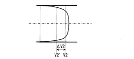
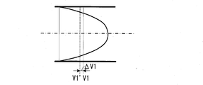
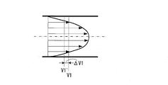
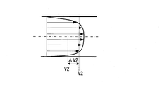
- the flow velocity distribution of the fluid in the measuring tube 1 changes depending on the flow rate. That is, when the flow rate is low, the flow becomes laminar, and when the flow rate is high, the flow becomes turbulent. For this reason, the flow velocity distribution in the pipe on the ultrasonic propagation path becomes a parabolic convex shape as shown in FIG. 18A in the laminar flow region with a small flow rate, and compared as shown in FIG. A flat shape.
- the flow rate correction coefficient k which is the ratio of the average flow velocity V ′ measured by the ultrasonic propagation path and the true flow velocity V, does not become the same value for laminar flow and turbulent flow.
- the difference between V1 and V1 ′ in the laminar flow area is the deviation ⁇ V1
- the difference between V2 and V2 ′ in the turbulent flow area is the deviation ⁇ V2
- the difference between the deviation ⁇ V1 in the laminar flow area and the deviation ⁇ V2 in the turbulent flow area is large. Therefore, the flow rate correction coefficient k1 in the laminar flow region and the flow rate correction coefficient k2 in the turbulent flow region are not equal (k1 ⁇ k2).
- the flow rate correction coefficient k has a flow rate dependency that changes abruptly on the laminar flow side.
- the flow rate correction coefficient k showing such a change characteristic is used, where the change amount of the flow rate correction coefficient k changes abruptly, the flow rate correction coefficient k applied to the flow rate correction coefficient k can be applied even if the flow rate measurement error is slight. The error is large, and as a result, the required flow rate error becomes large.
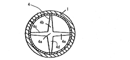
- Patent Document 1 proposes a technique of providing a built-in member 4 in the measurement tube 1 as shown in FIG.
- the built-in member 4 is formed in a star shape, and has a central portion as a blocking surface 4a and arms 4b to 4e extending in four directions from the blocking surface 4a.
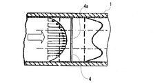
- a built-in member 4 is provided, as shown in FIG. 22, when the fluid flowing through the measuring tube 1 passes through the built-in member 4, the flow velocity of the fluid at the center is reduced by the blocking surface 4a, and the fluid at the peripheral portion The flow rate increases.
- the flow velocity distribution can be an averaged flow velocity distribution that does not have a conspicuous maximum value at the center of the pipe in both the laminar flow region and the turbulent flow region.
- the laminar flow becomes turbulent, and the deviation ⁇ V2 between the true flow velocity V2 in the turbulent flow region and the average flow velocity V2 ′ measured in the ultrasonic propagation path, and the true flow velocity V1 in the laminar flow region
- the difference from the deviation ⁇ V1 from the average flow velocity V1 ′ measured in the sound wave propagation path becomes smaller, and the change characteristic of the flow rate correction coefficient k approaches the flat change characteristic II.
- the built-in member 4 is provided between a pair of ultrasonic transceivers. For this reason, the ultrasonic wave propagating between the transceivers 2 and 3 is partially blocked, and the received ultrasonic wave reception signal is attenuated. There is a problem that the signal-to-noise ratio of the signal decreases due to the attenuation of the received signal, leading to a decrease in measurement accuracy. In addition, if an attempt is made to increase the voltage applied to the sensor in order to improve the SN ratio, there is a problem that the power consumption of the device is increased.
- the present invention has been made to solve such problems, and the object of the present invention is to enable highly accurate flow measurement over a wide flow range without lowering the SN ratio or increasing power consumption.
- An ultrasonic fluid measuring device is provided.
- the present invention provides a measurement tube through which a fluid to be measured flows, a first ultrasonic transmitter / receiver disposed on a peripheral surface upstream of the measurement tube, and a downstream of the measurement tube.
- a second ultrasonic transmitter / receiver disposed on the circumferential surface, a first ultrasonic transmitter / receiver, and a second ultrasonic transmitter / receiver connected to the first ultrasonic transmitter / receiver;
- a flow velocity distribution adjusting member for adjusting the distribution of the flow velocity distribution adjusting member, wherein a part of the shape in which the flow velocity distribution adjusting member is projected on a cross section orthogonal to the tube axis of the measurement tube is orthogonal to the tube axis of the measurement tube Arranged so that it overlaps a part of the locus that projected the propagation path of the
- the flow velocity distribution adjusting member is disposed upstream of the first and second ultrasonic transceivers. For this reason, propagation of ultrasonic waves between the first ultrasonic transmitter / receiver and the second ultrasonic transmitter / receiver is not hindered by the flow velocity distribution adjusting member.
- a part of the shape in which the flow velocity distribution adjusting member is projected on the cross section orthogonal to the tube axis of the measurement tube overlaps a part of the locus on which the ultrasonic propagation path is projected on the cross section orthogonal to the tube axis of the measurement tube.
- a flow velocity distribution adjusting member is arranged.
- the flow velocity of the fluid decreases downstream of the region where the flow velocity distribution adjusting member exists, and the fluid flow velocity increases downstream of the region where the flow velocity distribution adjusting member does not exist.
- the flow velocity distribution changes. Therefore, according to the present invention, the change characteristic of the flow rate correction coefficient from the turbulent flow region to the laminar flow region is brought close to a flat change characteristic without decreasing the SN ratio and increasing the power consumption, and the high accuracy over a wide flow range. Can be measured.
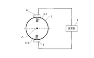
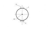
- FIG. 1A and 1B are schematic views showing an ultrasonic flowmeter according to an embodiment of the present invention.
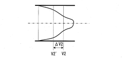
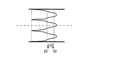
- FIG. 2A is a diagram showing a flow velocity distribution in the measurement tube in the case of turbulent flow without a flow velocity distribution adjusting member.
- FIG. 2B is a diagram showing the flow velocity distribution in the measurement tube in the case of turbulent flow with a flow velocity distribution adjusting member.
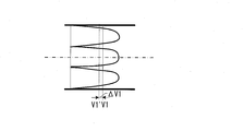
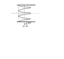
- FIG. 3A is a diagram showing a flow velocity distribution in the measurement tube in the case of a laminar flow without a flow velocity distribution adjusting member.
- FIG. 3B is a diagram showing the flow velocity distribution in the measurement tube in the case of laminar flow with a flow velocity distribution adjusting member.
- FIG. 4 is a diagram showing a change characteristic of the flow rate correction coefficient when there is no flow velocity distribution adjusting member and when there is no flow velocity distribution adjusting member.
- FIG. 5 is a view showing a modification of the flow velocity distribution adjusting member.
- FIG. 6 is a view showing a modification of the flow velocity distribution adjusting member.
- FIG. 7 is a view showing a modification of the flow velocity distribution adjusting member.
- FIG. 8 is a perspective view showing a modification of the flow velocity distribution adjusting member.
- 9A to 9E are perspective views showing modifications of the flow velocity distribution adjusting member.
- FIG. 10 is a perspective view showing an ultrasonic flowmeter that is Embodiment 1 of the present invention.
- FIG. 11 is a front view of the ultrasonic flow meter shown in FIG.
- FIG. 12A is a diagram showing a flow velocity distribution in the measurement tube in the case of turbulent flow without a flow velocity distribution adjusting member.
- FIG. 12B is a diagram showing a flow velocity distribution in the measurement tube in the case of a turbulent flow with a flow velocity distribution adjusting member.
- FIG. 13A is a diagram showing a flow velocity distribution in the measurement tube in the case of a laminar flow without a flow velocity distribution adjusting member.
- FIG. 13B is a diagram showing the flow velocity distribution in the measurement tube in the case of laminar flow with a flow velocity distribution adjusting member.
- FIG. 14 is the front view which looked at the ultrasonic flowmeter which is Example 2 of this invention from the side by which the flow velocity distribution adjustment member was engage
- FIG. 15A is a diagram showing a flow velocity distribution in the measurement tube in the case of turbulent flow without a flow velocity distribution adjusting member.
- FIG. 15B is a diagram illustrating a flow velocity distribution in the measurement tube in the case of a turbulent flow with a flow velocity distribution adjusting member.
- FIG. 16A is a diagram showing a flow velocity distribution in the measurement tube in the case of a laminar flow without a flow velocity distribution adjusting member.
- FIG. 16B is a diagram showing the flow velocity distribution in the measurement tube in the case of a laminar flow with a flow velocity distribution adjusting member.
- FIG. 17A and 17B are schematic views showing a conventional ultrasonic flowmeter.
- FIG. 18A is a diagram showing a flow velocity distribution in the measurement tube in the case of laminar flow.
- FIG. 18B is a diagram showing a flow velocity distribution in the measurement tube in the case of turbulent flow.
- FIG. 19 is a diagram illustrating a change characteristic of the flow rate correction coefficient.
- FIG. 20 is a diagram illustrating a desirable change characteristic of the flow rate correction coefficient.
- FIG. 21 is a view showing a star-shaped built-in member disclosed in Patent Document 1.
- FIG. 22 is a diagram for explaining a change in velocity distribution in the measurement tube when a star-shaped built-in member is provided.
- FIGS. 17A and 17B are schematic views showing an ultrasonic flowmeter which is an embodiment of the ultrasonic fluid measuring apparatus of the present invention.
- FIG. 1A shows a cross section parallel to the tube axis of the measurement tube
- FIG. 1B shows a cross section orthogonal to the tube axis of the measurement tube.
- the same reference numerals as those in FIGS. 17A and 17B denote the same or equivalent components as those described with reference to FIGS. 17A and 17B, and description thereof will be omitted.
- the first ultrasonic transceiver 2 is disposed on the outer peripheral surface on the upstream side of the measurement tube 1 through which the fluid to be measured flows, and the outer periphery on the downstream side of the measurement tube 1.
- a second ultrasonic transceiver 3 is arranged on the surface.
- the ultrasonic transmitter / receiver 2 and the ultrasonic transmitter / receiver 3 measure the flow velocity V of the fluid based on the difference in ultrasonic propagation time between the ultrasonic transmitter / receiver 2 and the ultrasonic transmitter / receiver 3.
- a flow velocity that adjusts the distribution of the flow velocity of the fluid in the measurement tube 1 in a pipeline upstream of the measurement tube 1 (a pipeline upstream of the first ultrasonic transceiver 2).
- a distribution adjusting member 5 is provided.
- the flow velocity distribution adjusting member 5 includes a first rectangular parallelepiped member 5-1 positioned above the inner peripheral surface of the measurement tube 1 and a second rectangular parallelepiped member positioned below the inner peripheral surface of the measuring tube 1.
- the lengthwise direction of the measuring tube 1 is arranged in the direction of the tube axis O.
- the flow velocity distribution adjusting member 5 a part of the shape obtained by projecting the members 5-1 and 5-2 on the cross section orthogonal to the tube axis O of the measurement tube 1 is ultrasonic in the cross section orthogonal to the tube axis O of the measurement tube 1 It is arranged so as to overlap a part of the locus projected the propagation path. That is, the flow velocity distribution adjusting member 5 is disposed so that a part of the flow velocity distribution adjusting member 5 overlaps a part of the ultrasonic wave propagation path when viewed from the direction parallel to the tube axis O of the measuring tube 1.
- 2A and 2B show a comparison of flow velocity distributions in the tube on the ultrasonic wave propagation path in the case of turbulent flow with and without the flow velocity distribution adjusting member 5.
- 2A shows a case where the flow velocity distribution adjusting member 5 is not provided
- FIG. 2B shows a case where the flow velocity distribution adjusting member 5 is provided.
- this ultrasonic flowmeter 100 when the fluid flowing through the measurement tube 1 passes through the flow velocity distribution adjusting member 5, the fluid after the portion where the member shape of the flow velocity distribution adjusting member 5 is present. The flow rate of the fluid decreases, and the fluid flow rate after the part without the member shape increases. However, in the turbulent region, the average flow velocity V2 'measured on the ultrasonic wave propagation path does not change much with and without the flow velocity distribution adjusting member 5.
- 3A and 3B show a comparison of flow velocity distributions in a tube on an ultrasonic wave propagation path in the case of laminar flow with and without the flow velocity distribution adjusting member 5.
- 3A shows the case where the flow velocity distribution adjusting member 5 is provided
- FIG. 3B shows the case where the flow velocity distribution adjusting member 5 is not provided.
- this ultrasonic flowmeter 100 when the fluid flowing through the measurement tube 1 passes through the flow velocity distribution adjusting member 5, the fluid after the portion where the member shape of the flow velocity distribution adjusting member 5 is present. The flow rate of the fluid decreases, and the fluid flow rate after the part without the member shape increases.
- the average flow velocity V1 'measured on the ultrasonic propagation path varies greatly depending on whether or not the flow velocity distribution adjusting member 5 is present.
- the flow velocity distribution adjusting member 5 rectangular parallelepiped members 5-1 and 5-2 are provided above and below the measuring tube 1.
- the same rectangular parallelepiped members 5-3 and 5-4 may be provided on the left and right sides of the measuring tube 1.
- a ring-shaped member 6 in which a large number of through holes 6 a are formed in the direction of the tube axis O of the measurement tube 1 may be provided as a flow velocity distribution adjusting member.
- a member 7 comprising an inner annular member 7-1, an outer annular member 7-2, and a large number of ribs (connection members) 7-3 is used as a flow velocity distribution adjusting member. It may be.
- the outer annular member 7-2 is a member that contacts the inner surface of the measuring tube 1.
- the inner annular member 7-1 is spaced apart from the inner surface of the outer annular member 7-2 and is disposed coaxially with the outer annular member 7-2.
- the rib 7-3 connects a plurality of spaces between the inner annular member 7-1 and the outer annular member 7-2 by connecting the inner annular member 7-1 and the outer annular member 7-2. Is divided into a space 7c.
- the flow velocity distribution adjusting member 7 (7A) has an inner annular surface 7a (inner annular member) in which the cross-sectional shape perpendicular to the tube axis O of the measuring tube 1 divides the central portion and the peripheral portion of the measuring tube 1. 7-1), a space surrounded by the outer annular surface 7b (outer annular member 7-2) surrounding the peripheral edge of the measuring tube 1, and the inner annular surface 7a and the outer annular surface 7b is divided into a plurality of spaces 7c.
- the shape has a connecting surface 7d (rib 7-3) to be divided.
- the inner annular surface 7a, the outer annular surface 7b, and the connecting surface 7d are shaped to have a predetermined length in the direction of the tube axis O of the measuring tube 1.
- the ultrasonic flowmeter 100 using the flow velocity distribution adjusting member 7A when the fluid flowing through the measurement tube 1 passes through the flow velocity distribution adjusting member 7A, it is divided by the space 7e having the inner diameter ⁇ 1 of the inner annular surface 7a and the connecting surface 7d. It passes through a plurality of spaces (divided spaces) 7c between the inner annular surface 7a and the outer annular surface 7b.
- the space 7e and the divided space 7c having an inner diameter ⁇ 1 of the inner annular surface 7a have a length in the direction of the tube axis O.
- the number of divided spaces 7c as shown in FIG. 9A is reduced to, for example, three, and the number of divided spaces 7c as shown in FIG. 9B is increased.
- 12 flow velocity distribution adjusting members 7C a flow velocity distribution adjusting member 7D in which the size of the divided space 7c as shown in FIG.
- the flow velocity distribution adjusting member 7E in which the length of the outer annular member 7-2 as shown in FIG. 9D is longer than that of the inner annular member 7-1, and the inner annular member 7-1 as shown in FIG. 9E.
- a flow velocity distribution adjusting member 7F whose length is longer than that of the outer annular member 7-2 is also conceivable.
- the fluid flow velocity decreases downstream of the region where the flow velocity distribution adjusting member 5 exists in one cross section in the measuring tube 1.
- the fluid flow velocity increases downstream of the region where the flow velocity distribution adjusting member 5 does not exist.
- the flow velocity distribution changes, so that the flow velocity V 'measured by the ultrasonic wave propagation path changes even if the fluid flow rate is the same.
- FIG. 10 shows an ultrasonic flowmeter using the flow velocity distribution adjusting member 7A as Example 1.
- a flow velocity distribution adjusting member 7A is detachably fitted in a pipe line 1-1 on the inlet side of the measuring pipe 1.
- the flow velocity distribution adjusting member 7A is fitted into the outlet side pipe line 1-2.
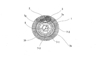
- the ultrasonic propagation path (ultrasonic propagation path) 8 between the ultrasonic transceiver 2 and the ultrasonic transceiver 3 is arranged in a cross section orthogonal to the tube axis O of the measuring tube 1.
- the ultrasonic transmitter / receiver 2 and the ultrasonic transmitter / receiver 3 are arranged on the outer peripheral surface of the measuring tube 1 so that the projected locus becomes a triangle shown in FIG.
- the ultrasonic wave propagation path 8 between the ultrasonic transmitter / receiver 2 and the ultrasonic transmitter / receiver 3 has an inclination with respect to the tube axis of the measuring tube 1 and 2 on the inner peripheral surface of the measuring tube 1. It has a point of reflection.
- the ultrasonic propagation path 8 having two reflection points is a technique already known as a triangle path, and by passing the propagation path through the flow path so that the ultrasonic wave passes through almost the entire area of the flow path cross section, It is known as a technique that can average the deviations well even for flows with deviations and can measure the flow rate with high accuracy.
- FIG. 12A and 12B show a comparison of flow velocity distribution in the tube on the ultrasonic propagation path in the case of turbulent flow with and without the flow velocity distribution adjusting member 7A.
- FIG. 12A shows the case where there is no flow velocity distribution adjusting member 7A
- FIG. 12B shows the case where there is a flow velocity distribution adjusting member 7A.
- this ultrasonic flowmeter 200 when the fluid flowing through the measurement tube 1 passes through the flow velocity distribution adjusting member 7A, at each side of the triangular locus of the ultrasonic propagation path 8, A speed distribution in which the amount of decrease in the flow rate at the center is larger than the amount of decrease in the flow rate at both ends.
- FIG. 13A and 13B show a comparison of flow velocity distributions in a tube on an ultrasonic wave propagation path in the case of laminar flow with and without the flow velocity distribution adjusting member 7A.
- FIG. 13A shows a case where there is no flow velocity distribution adjusting member 7A
- FIG. 13B shows a case where there is a flow velocity distribution adjusting member 7A.
- this ultrasonic flowmeter 200 when the fluid flowing through the measurement tube 1 passes through the flow velocity distribution adjusting member 7A, at each side of the triangular locus of the ultrasonic propagation path 8, A speed distribution in which the amount of decrease in the flow rate at the center is larger than the amount of decrease in the flow rate at both ends.
- the average flow velocity V ⁇ b> 1 ′ measured in the ultrasonic wave propagation path greatly changes.
- FIG. 14 shows an ultrasonic flowmeter using the flow velocity distribution adjusting member 7G as a second embodiment.
- convex walls 71 to 73 having a Y-shaped cross section are provided so as to overlap each corner portion of the triangular locus of the triangle path. That is, the convex walls 71 to 73 are arranged at positions overlapping with the reflection points of the ultrasonic wave propagation path when viewed from the direction of the tube axis O of the measurement tube 1.
- the shape of the cross section of the convex walls 71 to 73 perpendicular to the tube axis O may be Y-shaped or V-shaped.
- the convex walls 71 to 73 have a length in the direction of the tube axis O of the measuring tube 1.
- FIG. 15A and 15B show a comparison of flow velocity distributions in the tube on the ultrasonic wave propagation path in the case of turbulent flow with and without the flow velocity distribution adjusting member 7G.
- FIG. 15A shows a case where there is no flow velocity distribution adjusting member 7G
- FIG. 15B shows a case where there is a flow velocity distribution adjusting member 7G.
- the convex walls 71 to 73 having a Y-shaped cross section are provided, when the fluid flowing through the measurement tube 1 passes through the flow velocity distribution adjusting member 7G, the triangle of the ultrasonic propagation path 8 is obtained. In each side of the locus, the velocity distribution at the both ends is larger than the velocity decrease at the central portion.
- FIG. 16A and FIG. 16B show a comparison of flow velocity distributions in the tube on the ultrasonic propagation path in the case of laminar flow with and without the flow velocity distribution adjusting member 7G.
- FIG. 16A shows a case where there is no flow velocity distribution adjusting member 7G
- FIG. 16B shows a case where there is a flow velocity distribution adjusting member 7G.
- the convex walls 71 to 73 having a Y-shaped cross section are provided, when the fluid flowing through the measurement tube 1 passes through the flow velocity distribution adjusting member 7G, the triangle of the ultrasonic propagation path 8 is obtained. In each side of the locus, the velocity distribution at the both ends is larger than the velocity decrease at the central portion.
- the deviation ⁇ V2 between the true flow velocity V2 in the turbulent flow region and the average flow velocity V2 measured in the ultrasonic propagation path, and the true flow velocity V1 in the laminar flow region A difference from the deviation ⁇ V1 from the average flow velocity V1 ′ measured in the ultrasonic wave propagation path becomes small.
- the change characteristic of the flow rate correction coefficient k approaches the flat change characteristic II (see FIG. 4), and high-precision flow rate measurement is possible over a wide flow range.
- the locus of the ultrasonic wave propagation path 8 projected on the cross section orthogonal to the tube axis O of the measuring tube 1 is a triangle.
- the shape is not limited to a triangle, and for example, a quadrangle, a pentagon, etc. It may be a polygon.
- a quadrangular shape there are three reflection points on the inner peripheral surface of the measuring tube 1, and in the case of a pentagonal shape, there are four reflection points on the inner peripheral surface of the measuring tube 1.
- the flow velocity distribution adjusting member 7 (7A to 7G) is not necessarily provided so as to be detachable from the measuring tube 1, but may be fixed. Alternatively, the measurement tube 1 may be integrally formed. By making the flow velocity distribution adjusting member 7 (7A to 7G) detachable, maintenance becomes easy, and if foreign matter such as dust is clogged, it can be easily removed.
- the ultrasonic flowmeter for obtaining the flow rate from the measured fluid flow velocity has been described as an example.
- the ultrasonic flowmeter for obtaining the fluid flow velocity itself, the ultrasonic calorimeter for obtaining the heat amount from the flow rate, and the like have the same configuration. It goes without saying that can be adopted.
- SYMBOLS 1 ... Measuring tube, O ... Tube axis, 2 ... 1st ultrasonic transmitter / receiver, 3 ... 2nd ultrasonic transmitter / receiver, 4 ... Measuring part, 5, 6, 7 (7A-7G) ...
- Flow velocity distribution adjustment member 7-1 ... inner annular member, 7-2 ... outer annular member, 7-3 ... rib, 7a ... inner annular surface, 7b ... outer annular surface, 7c ... divided space, 7d ... connecting surface, 7e ... inner diameter ⁇ 1 space, 7f ... inner passage, 7g ... outer passage, 8 ... ultrasonic propagation path.
Landscapes
- Physics & Mathematics (AREA)
- Fluid Mechanics (AREA)
- General Physics & Mathematics (AREA)
- Acoustics & Sound (AREA)
- Electromagnetism (AREA)
- Engineering & Computer Science (AREA)
- Measuring Volume Flow (AREA)
- Mechanical Engineering (AREA)
- General Engineering & Computer Science (AREA)
Abstract
測定管(1)の上流側の管路に流速分布調整部材(5)を設ける。流速分布調整部材(5)は、測定管(1)の管軸(O)と直交する断面に流速分布調整部材(5)を投影した形状の一部が、上記断面に超音波の伝播経路を投影した軌跡の一部に重なるように配置されている。これにより、測定管(1)内における流速分布が変化し、乱流域での真の流速と超音波伝播経路で計測される平均流速との偏差と、層流域での偏差との差が小さくなり、流量補正係数の変化特性がフラットな変化特性に近づけられる。したがって、SN比の低下や消費電力を増加させることなく、広い流量範囲にわたって高精度の流量計測が可能となる。
Description
この発明は、超音波を用いて流体の流量などを測定する超音波流体測定装置に関するものである。
従来より、この種の超音波流体測定装置として、超音波を用いて流体の流量を測定する超音波流量計が用いられている。この超音波流量計では、図17Aおよび図17Bに示すように、測定対象の流体が流れる測定管1の上流側の外周面に第1の超音波送受信器2を配置し、下流側の外周面に第2の超音波送受信器3を配置し、超音波送受信器2と超音波送受信器3との間の超音波の伝播時間の差に基づいて流体の流速Vを測定し、この測定した流速Vと測定管1の断面積SとからQ=V×Sとして流体の流量を求める。
この流量Qを求める際の演算式を下記(1)~(4)式として示す。
t1=L/(c+V・cosθ) ・・・・(1)
t2=L/(c-V・cosθ) ・・・・(2)
V=c2・(t2-t1)/(2・L・cosθ) ・・・・(3)
Q=S・V ・・・・(4)
t1=L/(c+V・cosθ) ・・・・(1)
t2=L/(c-V・cosθ) ・・・・(2)
V=c2・(t2-t1)/(2・L・cosθ) ・・・・(3)
Q=S・V ・・・・(4)
但し、上記(1)~(4)式において、t1は超音波送受信器2から送信された超音波が超音波送受信器3で受信されるのに要した時間、t2は超音波送受信器3から送信された超音波が超音波送受信器2で受信されるのに要した時間、cは超音波の流体中における伝播速度、Lは超音波送受信器2と超音波送受信器3との相互間の距離(超音波伝播経路(パス)の距離)、θは測定管1の管軸Oに対する超音波伝播経路の傾きである。
この超音波流量計においては、超音波伝播経路上の平均流速V’を流速Vとして測定しているため、V’×Sにより計算される計測流量Q’は、真の流量Qと若干異なる。この超音波で計測した平均流速V’と管断面の平均流速(真の流速)Vとの比V’/V=Q’/Q=kが実流校正等で予め分かっていれば、この比を流量補正係数kとして、超音波で計測された超音波伝播経路上の平均流速V’と流量補正係数kとから、真の流量Qを求めることができる。
しかしながら、この流量補正係数kには次のような特徴がある。
測定管1内の流体の流速分布は流量に依存して変化する。すなわち、流量が少ない場合には層流となり、流量が多い場合には乱流となる。このため、超音波伝播経路上の管内の流速分布は、流量の少ない層流域においては図18Aに示すように放物状の凸型となり、流量の多い乱流域においては図18Bに示すように比較的平坦な形となる。
測定管1内の流体の流速分布は流量に依存して変化する。すなわち、流量が少ない場合には層流となり、流量が多い場合には乱流となる。このため、超音波伝播経路上の管内の流速分布は、流量の少ない層流域においては図18Aに示すように放物状の凸型となり、流量の多い乱流域においては図18Bに示すように比較的平坦な形となる。
したがって、超音波伝播経路で計測した平均流速V’と真の流速Vとの比である流量補正係数kは、層流と乱流とで同じ値とはならない。層流域において、超音波伝播経路で計測した平均流速V’をV1’、真の流速をV1とすると、その流量補正係数k1はk1=V1’/V1となる。乱流域において、超音波伝播経路で計測した平均流速V’をV2’、真の流速をV2とすると、その流量補正係数k2はk2=V2’/V2となる。層流域でのV1とV1’との差を偏差ΔV1、乱流域でのV2とV2’との差を偏差ΔV2とすると、層流域での偏差ΔV1と乱流域での偏差ΔV2との差が大きいために、層流域での流量補正係数k1と乱流域での流量補正係数k2とは等しくならないのである(k1≠k2)。
図19に示すように、流量補正係数kは、層流側で急激に変化する流量依存性をもつ。このような変化特性を示す流量補正係数kを用いた場合、流量補正係数kの変化量が急激に変化するところでは、流速計測の誤差がわずかであってもそれに適用される流量補正係数kの誤差が大きく、結果として求める流量の誤差が大きくなってしまう。
そこで、広い流量範囲にわたって高精度の流量計測を行うために、流量補正係数kの変化量をできるだけ小さくすることが望まれる。すなわち、図20に示すように、層流側で急激に変化する流量依存性を持つ変化特性Iを、比較的フラットな変化特性II(理想的には一定値)に近づけるようにすることが望まれる。
このために、例えば特許文献1は、図21に示すように、測定管1内に組み込み部材4を設ける技術を提案している。この組み込み部材4は、星形に形成されており、その中央部を阻止面4aとし、この阻止面4aより四方に伸びるアーム4b~4eを有している。このような組み込み部材4を設けると、図22に示すように、測定管1を流れる流体が組み込み部材4を通過する際、中央部の流体の流速が阻止面4aによって減少し、周縁部の流体の流速が増加する。これにより、流速分布を層流域でも乱流域でも管中心部での目立った最大値を有しない平均化された流速分布とすることができる。つまり、層流が乱流化されるものとなり、乱流域での真の流速V2と超音波伝播経路で計測される平均流速V2’との偏差ΔV2と、層流域での真の流速V1と超音波伝播経路で計測される平均流速V1’との偏差ΔV1との差が小さくなり、流量補正係数kの変化特性がフラットな変化特性IIに近づく。
上述した特許文献1に示された技術では、組み込み部材4を一対の超音波送受信器の間に設けている。このため、送受信器2,3間で伝播する超音波を部分的に遮り、伝播する超音波の受信信号が減衰する。この受信信号の減衰により信号のSN比が低下し、計測精度の低下を招いてしまうという問題がある。また、SN比向上のためにセンサへの印加電圧を上げようとすると、機器の消費電力の増大を招くという問題がある。
本発明は、このような課題を解決するためになされたもので、その目的とするところは、SN比の低下や消費電力を増加させることなく、広い流量範囲にわたって高精度の流量計測を可能とする超音波流体測定装置を提供することにある。
このような目的を達成するために本発明は、測定対象の流体が流れる測定管と、測定管の上流側の周面に配置された第1の超音波送受信器と、測定管の下流側の周面に配置された第2の超音波送受信器と、第1の超音波送受信器および第2の超音波送受信器に接続され、第1の超音波送受信器と第2の超音波送受信器との間の超音波の伝播時間の差に基づいて流体の流速を測定する測定部と、第1の超音波送受信器よりも上流側における測定管の管路に配置され、測定管内における流体の流速の分布を調整する流速分布調整部材とを備え、流速分布調整部材は、測定管の管軸と直交する断面に流速分布調整部材を投影した形状の一部が、測定管の管軸と直交する断面に超音波の伝播経路を投影した軌跡の一部に重なるように配置されている。
本発明では、第1および第2の超音波送受信器よりも上流側に流速分布調整部材が配置されている。このため、第1の超音波送受信器と第2の超音波送受信器との間の超音波の伝播が、流速分布調整部材により妨げられることはない。
また、測定管の管軸と直交する断面に流速分布調整部材を投影した形状の一部が、測定管の管軸と直交する断面に超音波の伝播経路を投影した軌跡の一部に重なるように、流速分布調整部材が配置されている。測定管内の一断面において流速分布調整部材が存在する領域の下流では流体の流速が減少し、流速分布調整部材が存在しない領域の下流では流体の流速が増加し、これにより超音波伝播経路上の流速分布が変化する。
したがって、本発明によれば、SN比の低下や消費電力を増大させることなく、乱流域から層流域にわたって流量補正係数の変化特性をフラットな変化特性に近づけるようにして、広い流量範囲にわたって高精度の流量計測が可能となる。
また、測定管の管軸と直交する断面に流速分布調整部材を投影した形状の一部が、測定管の管軸と直交する断面に超音波の伝播経路を投影した軌跡の一部に重なるように、流速分布調整部材が配置されている。測定管内の一断面において流速分布調整部材が存在する領域の下流では流体の流速が減少し、流速分布調整部材が存在しない領域の下流では流体の流速が増加し、これにより超音波伝播経路上の流速分布が変化する。
したがって、本発明によれば、SN比の低下や消費電力を増大させることなく、乱流域から層流域にわたって流量補正係数の変化特性をフラットな変化特性に近づけるようにして、広い流量範囲にわたって高精度の流量計測が可能となる。
以下、本発明の実施の形態を図面に基づいて詳細に説明する。
図1Aおよび図1Bは、本発明の超音波流体測定装置の一実施の形態である超音波流量計を示す模式図である。特に、図1Aは測定管の管軸に平行な断面を示し、図1Bは測定管の管軸と直交する断面を示している。図1Aおよび図1Bにおいて、図17Aおよび図17Bと同一符号は図17Aおよび図17Bを参照して説明した構成要素と同一または同等構成要素を示し、その説明は省略する。
図1Aおよび図1Bに示す超音波流量計100では、測定対象の流体が流れる測定管1の上流側の外周面に第1の超音波送受信器2が配置され、測定管1の下流側の外周面に第2の超音波送受信器3が配置されている。超音波送受信器2および超音波送受信器3には、超音波送受信器2と超音波送受信器3との間の超音波の伝播時間の差に基づいて流体の流速Vを測定し、流速Vと測定管1の断面積SとからQ=V×Sとして流体の流量を求める測定部4が接続されている。
この超音波流量計100では、測定管1の上流側の管路(第1の超音波送受信器2よりも上流側の管路)に、測定管1内における流体の流速の分布を調整する流速分布調整部材5を設けている。この流速分布調整部材5は、測定管1の内周面の上側に位置する第1の直方体状の部材5-1と、測定管1の内周面の下側に位置する第2の直方体状の部材5-2とからなり、その長手方向を測定管1の管軸Oの方向として配置されている。
流速分布調整部材5は、測定管1の管軸Oと直交する断面に部材5-1,5-2を投影した形状の一部が、測定管1の管軸Oと直交する断面に超音波の伝播経路を投影した軌跡の一部に重なるように配置されている。すなわち、測定管1の管軸Oと平行な方向からみたとき、流速分布調整部材5の一部が超音波の伝播経路の一部と重なるように、流速分布調整部材5が配置されている。
図2Aおよび図2Bに、流速分布調整部材5がない場合とある場合について、乱流の場合の超音波伝播経路上の管内の流速分布を比較して示す。図2Aは流速分布調整部材5がない場合を示し、図2Bは流速分布調整部材5がある場合を示す。この図を比較して分かるように、この超音波流量計100では、測定管1を流れる流体が流速分布調整部材5を通過する際、流速分布調整部材5の部材形状がある部分の後の流体の流速は減少し、部材形状が無い部分の後の流体の流速は増加する。しかし、乱流域では、流速分布調整部材5がある場合と無い場合とで、超音波伝播経路上で計測される平均流速V2’はあまり変化しない。
図3Aおよび図3Bに、流速分布調整部材5がない場合とある場合について、層流の場合の超音波伝播経路上の管内の流速分布を比較して示す。図3Aは流速分布調整部材5がある場合を示し、図3Bは流速分布調整部材5がない場合を示す。この図を比較して分かるように、この超音波流量計100では、測定管1を流れる流体が流速分布調整部材5を通過する際、流速分布調整部材5の部材形状がある部分の後の流体の流速は減少し、部材形状が無い部分の後の流体の流速は増加する。層流域の場合、流速分布調整部材5がある場合と無い場合とで、超音波伝播経路上で計測される平均流速V1’は大きく変化する。
この超音波流量計100では、流速分布調整部材5を設けることにより、図2Bおよび図3Bに示されるように、乱流域での真の流速V2と超音波伝播経路で計測される平均流速V2との偏差ΔV2と、層流域での真の流速V1と超音波伝播経路で計測される平均流速V1’との偏差ΔV1との差が小さくなる。これにより、図4に示されるように、流量補正係数kの変化特性がフラットな変化特性IIに近づき、広い流量範囲にわたって高精度の流量計測が可能となる。なお、図4において、「I」は流速分布調整部材5がない場合の変化特性、「II」は流速分布調整部材5がある場合の変化特性IIをそれぞれ示している。
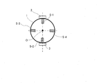
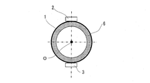
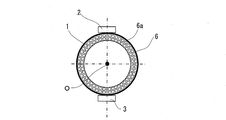
なお、この実施の形態では、流速分布調整部材5として、直方体状の部材5-1と5-2を測定管1内の上下に設けるようにした。しかし、図5に示すように、同様の直方体状の部材5-3と5-4を測定管1内の左右にも設けるようにしてもよい。また、図6に示すように、流速分布調整部材として、リング状の部材6を設けるようにしてもよい。さらに、図7に示すように、流速分布調整部材として、測定管1の管軸Oの方向に多数の貫通孔6aが形成されたリング状の部材6を設けるようにしてもよい。
また、図8に示すように、内側の環状部材7-1と、外側の環状部材7-2と、多数のリブ(連結部材)7-3とからなる部材7を流速分布調整部材として用いるようにしてもよい。外側の環状部材7-2は、測定管1の内面と接触する部材である。内側の環状部材7-1は、外側の環状部材7-2の内面と離間して、外側の環状部材7-2と同軸に配置される。リブ7-3は、内側の環状部材7-1と外側の環状部材7-2とを連結することによって、内側の環状部材7-1と外側の環状部材7-2との間の空間を複数の空間7cに分割する。
言い換えると、流速分布調整部材7(7A)は、測定管1の管軸Oと直交する断面の形状が、測定管1の中央部と周縁部とを分割する内側環状面7a(内側の環状部材7-1)と、測定管1の周縁部を取り囲む外側環状面7b(外側の環状部材7-2)と、内側環状面7aと外側環状面7bとで囲まれた空間を複数の空間7cに分割する連結面7d(リブ7-3)とを有する形状とされている。内側環状面7a、外側環状面7bおよび連結面7dは、測定管1の管軸Oの方向に所定の長さを有する形状とされている。
この流速分布調整部材7Aを用いた超音波流量計100では、測定管1を流れる流体が流速分布調整部材7Aを通過する際、内側環状面7aの内径φ1の空間7eと、連結面7dによって分割された内側環状面7aと外側環状面7bとの間の複数の空間(分割空間)7cを通過する。この内側環状面7aの内径φ1の空間7eと分割空間7cは管軸Oの方向に長さを有する。この内側環状面7aの内径φ1の空間7eの管軸Oの方向へ延びる通路(内側通路)7fと分割空間7cの管軸Oの方向へ延びる通路(外側通路)7gとを流体が通過する際、流体の管半径方向の速度成分が取り除かれ、その流体の流れが同一方向に規制(整流)される。
なお、流速分布調整部材7の変形例として、図9Aに示すような分割空間7cの数を少なくして例えば3つとした流速分布調整部材7B、図9Bに示すような分割空間7cの数を多くして例えば12個とした流速分布調整部材7C、図9C示すような分割空間7cの大きさを変えた流速分布調整部材7Dなどが考えられる。また、図9Dに示すような外側の環状部材7-2の長さを内側の環状部材7-1よりも長くした流速分布調整部材7E、図9Eに示すような内側の環状部材7-1の長さを外側の環状部材7-2よりも長くした流速分布調整部材7Fなども考えられる。
測定管1内の一断面において流速分布調整部材5が存在する領域の下流では、流体の流速が減少する。一方、流速分布調整部材5が存在しない領域の下流では、流体の流速が増加する。これにより流速分布が変化するため、流体の流量が同じでも、超音波伝播経路で計測される流速V’が変化する。
そこで、乱流域での真の流速V2と超音波伝播経路で計測される平均流速V2’との偏差ΔV2と、層流域での真の流速V1と超音波伝播経路で計測される平均流速V1’との偏差ΔV1との差ができるだけ小さくなるように流速分布調整部材5の形状を決めれば、乱流域から層流域にわたる流量補正係数kの特性変化をフラットな特性IIに近づけることができる。
〔実施例1〕
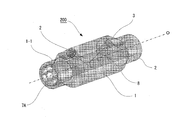
図10に、流速分布調整部材7Aを用いた超音波流量計を実施例1として示す。この超音波流量計200では、測定管1の入口側の管路1-1に流速分布調整部材7Aを着脱可能に嵌め込んでいる。なお、出口側の管路1-2を入口側として使用する場合には、出口側の管路1-2に流速分布調整部材7Aに嵌め込むようにする。
図10に、流速分布調整部材7Aを用いた超音波流量計を実施例1として示す。この超音波流量計200では、測定管1の入口側の管路1-1に流速分布調整部材7Aを着脱可能に嵌め込んでいる。なお、出口側の管路1-2を入口側として使用する場合には、出口側の管路1-2に流速分布調整部材7Aに嵌め込むようにする。
また、この超音波流量計200では、超音波送受信器2と超音波送受信器3との間の超音波の伝播経路(超音波伝播経路)8を測定管1の管軸Oと直交する断面に投影した軌跡が、図11に示す三角形となるように、超音波送受信器2と超音波送受信器3を測定管1の外周面に配置している。この場合、超音波送受信器2と超音波送受信器3との間の超音波伝播経路8は、測定管1の管軸に対して傾きを有し、かつ、測定管1の内周面において2点の反射点を有するものとなる。
この反射点を2点とする超音波伝播経路8は、トライアングルパスとしてすでに既知の技術であり、流路断面のほぼ全域に対し超音波が通るように伝播経路を流路内に通すことにより、偏りがある流れに対しても偏りをうまく平均化し、精度良く流量を計測することができる手法として知られている。
図12Aおよび図12Bに、流速分布調整部材7Aがない場合とある場合について、乱流の場合の超音波伝播経路上の管内の流速分布を比較して示す。図12Aは流速分布調整部材7Aがない場合を示し、図12Bは流速分布調整部材7Aがある場合を示す。この図を比較して分かるように、この超音波流量計200では、測定管1を流れる流体が流速分布調整部材7Aを通過する際、超音波伝播経路8の三角形の軌跡の各辺において、その中央部の流速の減少量が両端部の流速の減少量よりも大きい速度分布となる。しかし、乱流域の場合、後述する層流域の場合と比較して、中央部の流速の減少量は小さい。このため、乱流域では、超音波伝播経路で計測される平均流速V2’があまり変化しない。
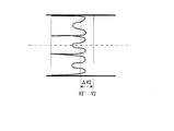
図13Aおよび図13Bに、流速分布調整部材7Aがない場合とある場合について、層流の場合の超音波伝播経路上の管内の流速分布を比較して示す。図13Aは流速分布調整部材7Aがない場合を示し、図13Bは流速分布調整部材7Aがある場合を示す。この図を比較して分かるように、この超音波流量計200では、測定管1を流れる流体が流速分布調整部材7Aを通過する際、超音波伝播経路8の三角形の軌跡の各辺において、その中央部の流速の減少量が両端部の流速の減少量よりも大きい速度分布となる。層流域の場合、前述した乱流域の場合と比較して、中央部の流速の減少量が大きい。このため、層流域では、超音波伝播経路で計測される平均流速V1’が大きく変化することになる。
この超音波流量計200では、流速分布調整部材7Aを設けることにより、図12Bおよび図13Bに示されるように、乱流域での真の流速V2と超音波伝播経路で計測される平均流速V2との偏差ΔV2と、層流域での真の流速V1と超音波伝播経路で計測される平均流速V1’との偏差ΔV1との差が小さくなる。これにより、流量補正係数kの変化特性がフラットな変化特性II(図4参照)に近づき、広い流量範囲にわたって高精度の流量計測が可能となる。また、流速分布調整部材7Aを流体が通過する際、内側通路7fと外側通路7gによってその流体の流れが整流されるので、高精度の流量計測が可能となる。
〔実施例2〕
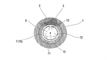
図14に、流速分布調整部材7Gを用いた超音波流量計を実施例2として示す。この流速分布調整部材7Gでは、トライアングルパスの三角形の軌跡の各コーナ部に重なるよう断面Y字状の凸状壁71~73を設けている。すなわち、凸状壁71~73は、測定管1の管軸Oの方向からみたとき、超音波伝播経路の反射点と重なる位置に配置される。凸状壁71~73の管軸Oと直交する断面の形状は、Y字状でもV字状でもよい。凸状壁71~73は測定管1の管軸Oの方向に長さを有している。
図14に、流速分布調整部材7Gを用いた超音波流量計を実施例2として示す。この流速分布調整部材7Gでは、トライアングルパスの三角形の軌跡の各コーナ部に重なるよう断面Y字状の凸状壁71~73を設けている。すなわち、凸状壁71~73は、測定管1の管軸Oの方向からみたとき、超音波伝播経路の反射点と重なる位置に配置される。凸状壁71~73の管軸Oと直交する断面の形状は、Y字状でもV字状でもよい。凸状壁71~73は測定管1の管軸Oの方向に長さを有している。
図15Aおよび図15Bに、流速分布調整部材7Gがない場合とある場合について、乱流の場合の超音波伝播経路上の管内の流速分布を比較して示す。図15Aは流速分布調整部材7Gがない場合を示し、図15Bは流速分布調整部材7Gがある場合を示す。この図を比較して分かるように、断面Y字状の凸状壁71~73を設けた場合、測定管1を流れる流体が流速分布調整部材7Gを通過する際、超音波伝播経路8の三角形の軌跡の各辺において、その両端部の流速の減少量が中央部の流速の減少量よりも大きい速度分布となる。しかし、乱流域の場合、後述する層流域の場合と比較して、両端部の流速の減少量は小さい。これにより、乱流域では、超音波伝播経路で計測される平均流速V2’があまり変化しない。
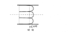
図16Aおよび図16Bに、流速分布調整部材7Gがない場合とある場合について、層流の場合の超音波伝播経路上の管内の流速分布を比較して示す。図16Aは流速分布調整部材7Gがない場合を示し、図16Bは流速分布調整部材7Gがある場合を示す。この図を比較して分かるように、断面Y字状の凸状壁71~73を設けた場合、測定管1を流れる流体が流速分布調整部材7Gを通過する際、超音波伝播経路8の三角形の軌跡の各辺において、その両端部の流速の減少量が中央部の流速の減少量よりも大きい速度分布となる。層流域の場合、前述した乱流域の場合と比較して、両端部の流速の減少量が大きい。このため、層流域では、超音波伝播経路で計測される平均流速V1’が大きく変化することになる。
したがって、流速分布調整部材7Aを設けた場合と同様に、乱流域での真の流速V2と超音波伝播経路で計測される平均流速V2との偏差ΔV2と、層流域での真の流速V1と超音波伝播経路で計測される平均流速V1’との偏差ΔV1との差が小さくなる。これにより、流量補正係数kの変化特性がフラットな変化特性II(図4参照)に近づき、広い流量範囲にわたって高精度の流量計測を可能となる。
なお、実施例1,2では、測定管1の管軸Oと直交する断面に超音波伝播経路8を投影した軌跡を三角形としたが、三角形に限られるものではなく、例えば四角形、五角形などの多角形としてもよい。四角形とした場合、測定管1の内周面における反射点は3点となり、五角形とした場合、測定管1の内周面における反射点は4点となる。
また、流速分布調整部材7(7A~7G)は、必ずしも測定管1に着脱可能に設けるようにしなくてもよく、固定するようにしてもよい。また、測定管1に一体的に作り込むようにしてもよい。流速分布調整部材7(7A~7G)を着脱可能とすることにより、メンテナンスが容易となり、ごみなどの異物が詰まった場合、簡単に除去することが可能となる。
また、以上では、測定した流体の流速から流量を求める超音波流量計を例にとって説明したが、流体の流速そのものを求める超音波流速計、流量から熱量を求める超音波熱量計などでも同様の構成を採用できることは言うまでもない。
〔実施の形態の拡張〕
本発明は上記の実施の形態および実施例に限定されるものではない。本発明の構成や詳細には、本発明の技術思想の範囲内で当業者が理解し得る様々な変更をすることができる。また、各実施の形態および実施例については、矛盾しない範囲で任意に組み合わせて実施することができる。
本発明は上記の実施の形態および実施例に限定されるものではない。本発明の構成や詳細には、本発明の技術思想の範囲内で当業者が理解し得る様々な変更をすることができる。また、各実施の形態および実施例については、矛盾しない範囲で任意に組み合わせて実施することができる。
1…測定管、O…管軸、2…第1の超音波送受信器、3…第2の超音波送受信器、4…測定部、5,6,7(7A~7G)…流速分布調整部材、7-1…内側の環状部材、7-2…外側の環状部材、7-3…リブ、7a…内側環状面、7b…外側環状面、7c…分割空間、7d…連結面、7e…内径φ1の空間、7f…内側通路、7g…外側通路、8…超音波伝播経路。
Claims (9)
- 測定対象の流体が流れる測定管と、
前記測定管の上流側の周面に配置された第1の超音波送受信器と、
前記測定管の下流側の周面に配置された第2の超音波送受信器と、
前記第1の超音波送受信器および前記第2の超音波送受信器に接続され、前記第1の超音波送受信器と前記第2の超音波送受信器との間の超音波の伝播時間の差に基づいて前記流体の流速を測定する測定部と、
前記第1の超音波送受信器よりも上流側における前記測定管の管路に配置され、前記測定管内における前記流体の流速の分布を調整する流速分布調整部材とを備え、
前記流速分布調整部材は、前記測定管の管軸と直交する断面に前記流速分布調整部材を投影した形状の一部が、前記測定管の管軸と直交する断面に前記超音波の伝播経路を投影した軌跡の一部に重なるように配置されている
超音波流体測定装置。 - 前記超音波の伝播経路は、前記測定管の管軸に対して傾きを有し、かつ、前記測定管の内面に少なくとも2点の反射点を有する
請求項1に記載された超音波流体測定装置。 - 前記流速分布調整部材は、
前記測定管の中央部と周縁部とを分割する内側環状部材と、
前記測定管の周縁部を取り囲む外側環状部材と、
前記内側環状部材と前記外側環状部材とを連結することによって、前記内側環状面と前記外側環状面との間の空間を複数の空間に分割する連結部材とを含む
請求項1に記載された超音波流体測定装置。 - 前記測定管の管軸と直交する断面に前記超音波の伝播経路を投影した軌跡が多角形である
請求項1に記載された超音波流体測定装置。 - 前記多角形は、三角形である
請求項4に記載された超音波流体測定装置。 - 前記流速分布調整部材は、直方体状の部材からなる
請求項1に記載された超音波流体測定装置。 - 前記流速分布調整部材は、リング状の部材からなる
請求項1に記載された超音波流体測定装置。 - 前記リング状の部材は、前記測定管の管軸方向に形成された複数の貫通孔を含む
請求項7に記載された超音波流体測定装置。 - 前記流速分布調整部材は、前記測定管の管軸方向からみたとき、前記超音波の伝播経路の反射点と重なる位置に配置され、かつ、前記測定管の管軸と直交する断面がY字状またはV字状をした複数の部材からなる
請求項1に記載された超音波流体測定装置。
Priority Applications (2)
| Application Number | Priority Date | Filing Date | Title |
|---|---|---|---|
| KR1020147021877A KR101616662B1 (ko) | 2012-02-28 | 2013-02-22 | 초음파 유체 측정 장치 |
| CN201380010867.9A CN104136892B (zh) | 2012-02-28 | 2013-02-22 | 超声波流体测定装置 |
Applications Claiming Priority (2)
| Application Number | Priority Date | Filing Date | Title |
|---|---|---|---|
| JP2012-041377 | 2012-02-28 | ||
| JP2012041377A JP5815437B2 (ja) | 2012-02-28 | 2012-02-28 | 超音波流体測定装置 |
Publications (1)
| Publication Number | Publication Date |
|---|---|
| WO2013129246A1 true WO2013129246A1 (ja) | 2013-09-06 |
Family
ID=49082446
Family Applications (1)
| Application Number | Title | Priority Date | Filing Date |
|---|---|---|---|
| PCT/JP2013/054480 Ceased WO2013129246A1 (ja) | 2012-02-28 | 2013-02-22 | 超音波流体測定装置 |
Country Status (4)
| Country | Link |
|---|---|
| JP (1) | JP5815437B2 (ja) |
| KR (1) | KR101616662B1 (ja) |
| CN (1) | CN104136892B (ja) |
| WO (1) | WO2013129246A1 (ja) |
Cited By (6)
| Publication number | Priority date | Publication date | Assignee | Title |
|---|---|---|---|---|
| CN103808380A (zh) * | 2013-12-23 | 2014-05-21 | 浙江先芯科技有限公司 | 一种用于超声波流量计量仪表的流量快速跟踪方法 |
| US9297679B2 (en) | 2014-01-14 | 2016-03-29 | General Electric Company | Flowmeter with a flow conditioner formed by a protrusion having restriction provided upstream of the measurement section |
| US9372106B2 (en) | 2014-01-14 | 2016-06-21 | General Electric Company | Non-circular flowmeter |
| WO2018200056A1 (en) * | 2017-04-24 | 2018-11-01 | Sensus Spectrum, Llc | Flow conditioners for use normalizing flow in meters and related systems |
| EP4273512A1 (de) * | 2022-05-04 | 2023-11-08 | Levitronix GmbH | Ultraschall-messsystem und messröhre für ein solches |
| EP4273511A1 (de) * | 2022-05-04 | 2023-11-08 | Sartorius Stedim Biotech GmbH | Vorrichtung zum anordnen an einer fluidführenden leitung und zum anbringen einer durchflussmesseinrichtung, und verfahren zur erfassung einer messgrösse des von einer leitung geführten fluids |
Families Citing this family (4)
| Publication number | Priority date | Publication date | Assignee | Title |
|---|---|---|---|---|
| JP7126048B2 (ja) * | 2018-08-08 | 2022-08-26 | パナソニックIpマネジメント株式会社 | 超音波流量計 |
| DE102019115590B4 (de) | 2019-06-07 | 2025-10-02 | Krohne Ag | Ultraschalldurchflussmessgerät |
| KR102718998B1 (ko) * | 2023-11-10 | 2024-10-16 | (주)에이치에스씨엠티 | 습식 다회선 초음파 유량계의 현장 교정방법 |
| CN120507536B (zh) * | 2025-07-21 | 2025-09-30 | 山西沣庆恒能源科技有限公司 | 一种基于超声波风速仪的超声波风速探测方法 |
Citations (7)
| Publication number | Priority date | Publication date | Assignee | Title |
|---|---|---|---|---|
| JP2001021399A (ja) * | 1999-07-05 | 2001-01-26 | Toho Gas Co Ltd | 超音波式ガスメータ |
| JP2004157101A (ja) * | 2002-09-11 | 2004-06-03 | Fuji Electric Retail Systems Co Ltd | 超音波流量計 |
| JP2004520573A (ja) * | 2000-11-30 | 2004-07-08 | ランディス+ギュル・ゲゼルシャフト・ミット・ベシュレンクテル・ハフツング | 流量計 |
| EP1775560A2 (en) * | 2005-10-14 | 2007-04-18 | Kamstrup A/S | Flow straightener for an ultrasonic flow meter |
| EP1876427A1 (de) * | 2006-07-05 | 2008-01-09 | Landis+Gyr GmbH | Ultraschall-durchflussmesser mit einer tubulatorkomponente im einlaufbereich |
| JP2010266345A (ja) * | 2009-05-15 | 2010-11-25 | Panasonic Corp | 流量計測装置 |
| JP2012132801A (ja) * | 2010-12-22 | 2012-07-12 | Panasonic Corp | 超音波流量計 |
Family Cites Families (2)
| Publication number | Priority date | Publication date | Assignee | Title |
|---|---|---|---|---|
| JP2803170B2 (ja) | 1989-06-07 | 1998-09-24 | 日本電気株式会社 | 半導体ウェハー搬送装置 |
| JPH06241858A (ja) * | 1993-02-15 | 1994-09-02 | Oval Corp | 整流装置 |
-
2012
- 2012-02-28 JP JP2012041377A patent/JP5815437B2/ja not_active Expired - Fee Related
-
2013
- 2013-02-22 CN CN201380010867.9A patent/CN104136892B/zh not_active Expired - Fee Related
- 2013-02-22 WO PCT/JP2013/054480 patent/WO2013129246A1/ja not_active Ceased
- 2013-02-22 KR KR1020147021877A patent/KR101616662B1/ko not_active Expired - Fee Related
Patent Citations (7)
| Publication number | Priority date | Publication date | Assignee | Title |
|---|---|---|---|---|
| JP2001021399A (ja) * | 1999-07-05 | 2001-01-26 | Toho Gas Co Ltd | 超音波式ガスメータ |
| JP2004520573A (ja) * | 2000-11-30 | 2004-07-08 | ランディス+ギュル・ゲゼルシャフト・ミット・ベシュレンクテル・ハフツング | 流量計 |
| JP2004157101A (ja) * | 2002-09-11 | 2004-06-03 | Fuji Electric Retail Systems Co Ltd | 超音波流量計 |
| EP1775560A2 (en) * | 2005-10-14 | 2007-04-18 | Kamstrup A/S | Flow straightener for an ultrasonic flow meter |
| EP1876427A1 (de) * | 2006-07-05 | 2008-01-09 | Landis+Gyr GmbH | Ultraschall-durchflussmesser mit einer tubulatorkomponente im einlaufbereich |
| JP2010266345A (ja) * | 2009-05-15 | 2010-11-25 | Panasonic Corp | 流量計測装置 |
| JP2012132801A (ja) * | 2010-12-22 | 2012-07-12 | Panasonic Corp | 超音波流量計 |
Cited By (7)
| Publication number | Priority date | Publication date | Assignee | Title |
|---|---|---|---|---|
| CN103808380A (zh) * | 2013-12-23 | 2014-05-21 | 浙江先芯科技有限公司 | 一种用于超声波流量计量仪表的流量快速跟踪方法 |
| US9297679B2 (en) | 2014-01-14 | 2016-03-29 | General Electric Company | Flowmeter with a flow conditioner formed by a protrusion having restriction provided upstream of the measurement section |
| US9372106B2 (en) | 2014-01-14 | 2016-06-21 | General Electric Company | Non-circular flowmeter |
| WO2018200056A1 (en) * | 2017-04-24 | 2018-11-01 | Sensus Spectrum, Llc | Flow conditioners for use normalizing flow in meters and related systems |
| EP4273512A1 (de) * | 2022-05-04 | 2023-11-08 | Levitronix GmbH | Ultraschall-messsystem und messröhre für ein solches |
| EP4273511A1 (de) * | 2022-05-04 | 2023-11-08 | Sartorius Stedim Biotech GmbH | Vorrichtung zum anordnen an einer fluidführenden leitung und zum anbringen einer durchflussmesseinrichtung, und verfahren zur erfassung einer messgrösse des von einer leitung geführten fluids |
| WO2023213896A1 (de) * | 2022-05-04 | 2023-11-09 | Sartorius Stedim Biotech Gmbh | VORRICHTUNG ZUM ANORDNEN AN EINER FLUIDFÜHRENDEN LEITUNG UND ZUM ANBRINGEN EINER DURCHFLUSSMESSEINRICHTUNG, UND VERFAHREN ZUR ERFASSUNG EINER MESSGRÖßE DES VON EINER LEITUNG GEFÜHRTEN FLUIDS |
Also Published As
| Publication number | Publication date |
|---|---|
| JP5815437B2 (ja) | 2015-11-17 |
| CN104136892B (zh) | 2016-10-26 |
| KR101616662B1 (ko) | 2016-04-28 |
| KR20140112540A (ko) | 2014-09-23 |
| JP2013178126A (ja) | 2013-09-09 |
| CN104136892A (zh) | 2014-11-05 |
Similar Documents
| Publication | Publication Date | Title |
|---|---|---|
| WO2013129246A1 (ja) | 超音波流体測定装置 | |
| US9506484B2 (en) | Flow conditioner and method for optimization | |
| US20140020478A1 (en) | Ultrasonic wedge and method for determining the speed of sound in same | |
| CA2778063C (en) | Accessory apparatus for flowmeters | |
| US6644132B1 (en) | Flow profile conditioner for pipe flow systems | |
| EP1775560A2 (en) | Flow straightener for an ultrasonic flow meter | |
| CN103547893A (zh) | 超声波流量计 | |
| US7845240B1 (en) | Device and method for determining a flow characteristic of a fluid in a conduit | |
| WO2013129197A1 (ja) | 超音波流体測定装置 | |
| US8146442B2 (en) | Device and method for measuring a flow characteristic of a fluid in a conduit | |
| EP2282178B1 (en) | Ultrasonic flowmeter for measuring a flow characteristic of a fluid in a conduit | |
| CN112050874A (zh) | 超声波流量测量计、其在闭塞器具中的使用和闭塞器具 | |
| JP5816831B2 (ja) | 超音波流量計 | |
| US11885654B2 (en) | Ultrasonic flowmeter, use of an ultrasonic flowmeter in a shut-off device and shut-off device | |
| JP2009264906A (ja) | 流量計 | |
| EP2278280A1 (en) | Device and method for determining a flow characteristic of a fluid in a conduit | |
| JP2013250254A (ja) | 超音波式スパイロメータの多重反射防止整流管 | |
| JP7611751B2 (ja) | 流量計 | |
| CN103630271A (zh) | 一种缩径式结构超声波热量表 | |
| US20260022957A1 (en) | Multi-part assembly for retrofitting into a passage of a mechanical flow meter | |
| EP4647729A1 (en) | An ultrasonic flow meter | |
| JP7678712B2 (ja) | 超音波流量計 | |
| JP2025064348A (ja) | 超音波式流量計 | |
| JP2016099139A (ja) | 超音波流量計 | |
| CN105890684A (zh) | 一种采用高斯-雅可比多项式确定声道位置的设置新方法 |
Legal Events
| Date | Code | Title | Description |
|---|---|---|---|
| 121 | Ep: the epo has been informed by wipo that ep was designated in this application |
Ref document number: 13755648 Country of ref document: EP Kind code of ref document: A1 |
|
| ENP | Entry into the national phase |
Ref document number: 20147021877 Country of ref document: KR Kind code of ref document: A |
|
| NENP | Non-entry into the national phase |
Ref country code: DE |
|
| 122 | Ep: pct application non-entry in european phase |
Ref document number: 13755648 Country of ref document: EP Kind code of ref document: A1 |