WO2013129142A1 - 圧電素子用多孔質樹脂シートおよびその製造方法 - Google Patents
圧電素子用多孔質樹脂シートおよびその製造方法 Download PDFInfo
- Publication number
- WO2013129142A1 WO2013129142A1 PCT/JP2013/053735 JP2013053735W WO2013129142A1 WO 2013129142 A1 WO2013129142 A1 WO 2013129142A1 JP 2013053735 W JP2013053735 W JP 2013053735W WO 2013129142 A1 WO2013129142 A1 WO 2013129142A1
- Authority
- WO
- WIPO (PCT)
- Prior art keywords
- hollow particles
- sheet
- resin
- resin sheet
- charge
- Prior art date
Links
Images


Classifications
-
- C—CHEMISTRY; METALLURGY
- C08—ORGANIC MACROMOLECULAR COMPOUNDS; THEIR PREPARATION OR CHEMICAL WORKING-UP; COMPOSITIONS BASED THEREON
- C08J—WORKING-UP; GENERAL PROCESSES OF COMPOUNDING; AFTER-TREATMENT NOT COVERED BY SUBCLASSES C08B, C08C, C08F, C08G or C08H
- C08J9/00—Working-up of macromolecular substances to porous or cellular articles or materials; After-treatment thereof
- C08J9/009—Use of pretreated compounding ingredients
-
- C—CHEMISTRY; METALLURGY
- C08—ORGANIC MACROMOLECULAR COMPOUNDS; THEIR PREPARATION OR CHEMICAL WORKING-UP; COMPOSITIONS BASED THEREON
- C08J—WORKING-UP; GENERAL PROCESSES OF COMPOUNDING; AFTER-TREATMENT NOT COVERED BY SUBCLASSES C08B, C08C, C08F, C08G or C08H
- C08J9/00—Working-up of macromolecular substances to porous or cellular articles or materials; After-treatment thereof
- C08J9/32—Working-up of macromolecular substances to porous or cellular articles or materials; After-treatment thereof from compositions containing microballoons, e.g. syntactic foams
-
- H—ELECTRICITY
- H01—ELECTRIC ELEMENTS
- H01G—CAPACITORS; CAPACITORS, RECTIFIERS, DETECTORS, SWITCHING DEVICES OR LIGHT-SENSITIVE DEVICES, OF THE ELECTROLYTIC TYPE
- H01G7/00—Capacitors in which the capacitance is varied by non-mechanical means; Processes of their manufacture
- H01G7/02—Electrets, i.e. having a permanently-polarised dielectric
- H01G7/028—Electrets, i.e. having a permanently-polarised dielectric having a heterogeneous dielectric
-
- C—CHEMISTRY; METALLURGY
- C08—ORGANIC MACROMOLECULAR COMPOUNDS; THEIR PREPARATION OR CHEMICAL WORKING-UP; COMPOSITIONS BASED THEREON
- C08J—WORKING-UP; GENERAL PROCESSES OF COMPOUNDING; AFTER-TREATMENT NOT COVERED BY SUBCLASSES C08B, C08C, C08F, C08G or C08H
- C08J2205/00—Foams characterised by their properties
- C08J2205/04—Foams characterised by their properties characterised by the foam pores
- C08J2205/044—Micropores, i.e. average diameter being between 0,1 micrometer and 0,1 millimeter
-
- C—CHEMISTRY; METALLURGY
- C08—ORGANIC MACROMOLECULAR COMPOUNDS; THEIR PREPARATION OR CHEMICAL WORKING-UP; COMPOSITIONS BASED THEREON
- C08J—WORKING-UP; GENERAL PROCESSES OF COMPOUNDING; AFTER-TREATMENT NOT COVERED BY SUBCLASSES C08B, C08C, C08F, C08G or C08H
- C08J2205/00—Foams characterised by their properties
- C08J2205/04—Foams characterised by their properties characterised by the foam pores
- C08J2205/046—Unimodal pore distribution
-
- C—CHEMISTRY; METALLURGY
- C08—ORGANIC MACROMOLECULAR COMPOUNDS; THEIR PREPARATION OR CHEMICAL WORKING-UP; COMPOSITIONS BASED THEREON
- C08J—WORKING-UP; GENERAL PROCESSES OF COMPOUNDING; AFTER-TREATMENT NOT COVERED BY SUBCLASSES C08B, C08C, C08F, C08G or C08H
- C08J2327/00—Characterised by the use of homopolymers or copolymers of compounds having one or more unsaturated aliphatic radicals, each having only one carbon-to-carbon double bond, and at least one being terminated by a halogen; Derivatives of such polymers
- C08J2327/02—Characterised by the use of homopolymers or copolymers of compounds having one or more unsaturated aliphatic radicals, each having only one carbon-to-carbon double bond, and at least one being terminated by a halogen; Derivatives of such polymers not modified by chemical after-treatment
- C08J2327/12—Characterised by the use of homopolymers or copolymers of compounds having one or more unsaturated aliphatic radicals, each having only one carbon-to-carbon double bond, and at least one being terminated by a halogen; Derivatives of such polymers not modified by chemical after-treatment containing fluorine atoms
- C08J2327/18—Homopolymers or copolymers of tetrafluoroethylene
-
- C—CHEMISTRY; METALLURGY
- C08—ORGANIC MACROMOLECULAR COMPOUNDS; THEIR PREPARATION OR CHEMICAL WORKING-UP; COMPOSITIONS BASED THEREON
- C08J—WORKING-UP; GENERAL PROCESSES OF COMPOUNDING; AFTER-TREATMENT NOT COVERED BY SUBCLASSES C08B, C08C, C08F, C08G or C08H
- C08J2327/00—Characterised by the use of homopolymers or copolymers of compounds having one or more unsaturated aliphatic radicals, each having only one carbon-to-carbon double bond, and at least one being terminated by a halogen; Derivatives of such polymers
- C08J2327/02—Characterised by the use of homopolymers or copolymers of compounds having one or more unsaturated aliphatic radicals, each having only one carbon-to-carbon double bond, and at least one being terminated by a halogen; Derivatives of such polymers not modified by chemical after-treatment
- C08J2327/12—Characterised by the use of homopolymers or copolymers of compounds having one or more unsaturated aliphatic radicals, each having only one carbon-to-carbon double bond, and at least one being terminated by a halogen; Derivatives of such polymers not modified by chemical after-treatment containing fluorine atoms
- C08J2327/20—Homopolymers or copolymers of hexafluoropropene
-
- C—CHEMISTRY; METALLURGY
- C08—ORGANIC MACROMOLECULAR COMPOUNDS; THEIR PREPARATION OR CHEMICAL WORKING-UP; COMPOSITIONS BASED THEREON
- C08J—WORKING-UP; GENERAL PROCESSES OF COMPOUNDING; AFTER-TREATMENT NOT COVERED BY SUBCLASSES C08B, C08C, C08F, C08G or C08H
- C08J2379/00—Characterised by the use of macromolecular compounds obtained by reactions forming in the main chain of the macromolecule a linkage containing nitrogen with or without oxygen, or carbon only, not provided for in groups C08J2361/00 - C08J2377/00
- C08J2379/04—Polycondensates having nitrogen-containing heterocyclic rings in the main chain; Polyhydrazides; Polyamide acids or similar polyimide precursors
- C08J2379/08—Polyimides; Polyester-imides; Polyamide-imides; Polyamide acids or similar polyimide precursors
Definitions
- the present invention relates to a porous resin sheet for piezoelectric elements in which hollow particles having a conductive substance on the surface are dispersed in a matrix resin, and a method for producing the same.
- Patent Document 1 discloses a molding formed by blending glass hollow particles with an organic polymer such as polypropylene. An electret formed by injecting a charge into a body is disclosed.
- the polymer material has a porous structure as in Patent Document 1
- electric charges are easily held in the pores formed in the polymer material, and high piezoelectric characteristics are exhibited.
- the characteristic degradation at high temperature is also large.
- the electret disclosed in Patent Document 1 can exhibit good piezoelectric properties in the short term, but even if glass hollow particles are used as they are, they cannot maintain the piezoelectric properties over a long period of time. I understood.
- Patent Document 2 includes bubbles having an average maximum vertical chord length of 1 to 40 ⁇ m and an average aspect ratio of 0.7 to 4.0, and a volume.
- a porous resin sheet for piezoelectric / pyroelectric elements containing ceramic particles having a porosity of 20 to 75% and a dielectric constant higher than that of the resin component is disclosed.
- a solvent extraction step is required to remove the phase separation agent used in the production process of the porous resin sheet for piezoelectric / pyroelectric elements, industrial practical application is difficult.
- the initial value of piezoelectricity and its retention are important.
- As a method for increasing the initial value of the piezoelectricity it is possible to increase the porosity of the porous structure so as to retain a large amount of polarized charges, and to make the structure easy to deform.
- the retention it is important to maintain a distance that does not cause an electrical short circuit between the polarized charges held in the hole portions.
- increasing the porosity in order to increase the piezoelectricity leads to a decrease in the distance between the holes that retain electric charges in the same volume, leading to a decrease in retention. Met.
- the present invention is capable of maintaining high piezoelectric characteristics over a long period of time in a wide operating temperature range, environmental resistance (resistance to extreme environments such as extreme temperature and humidity changes, shock and vibration), and heat resistance.
- An object is to provide an excellent porous resin sheet for piezoelectric elements and a method for producing the same.
- the present inventors in a piezoelectric material using a polymer material, blend charge-induced hollow particles in which a conductive substance is attached to at least a part of the surface of the hollow particles in a matrix resin made of an organic polymer.
- the inventors have found that high piezoelectric characteristics can be maintained over a long period of time, and have completed the present invention.
- the porous resin sheet for piezoelectric elements of the present invention comprises at least charge-induced hollow particles dispersed in a matrix resin, and the charge-induced hollow particles have a conductive substance on at least a part of the surface of the hollow particles. It is preferable that the conductive substance is a substance having higher conductivity than the hollow particles and the matrix resin.
- the conductive material described above is a method in which a part or all of the substance having a hydrocarbon group attached to at least a part of the surface of the hollow particle is heated in a matrix resin in which the hydrocarbon group is under an oxygen blocking condition.
- Conditions that cause conductivity by decomposing for example, 10 to 6 hours at a temperature of 100 to 350 ° C. that is lower than the thermal decomposition start temperature of the matrix resin, under reduced pressure to increased pressure (eg 0.1 Pa to 10 MPa) ) To be obtained by heat treatment.
- the thermal decomposition starting temperature of the substance having a hydrocarbon group under oxygen-blocking conditions is less than the thermal decomposition starting temperature of the matrix resin, preferably 50 to 300 ° C., preferably from the thermal decomposition starting temperature of the matrix resin, preferably A low temperature of about 100 to 250 ° C. is preferable from the viewpoint of the performance of the obtained sheet (for example, the initial value of the piezoelectricity is high and the decrease in the piezoelectricity with time is small).
- the substance having a hydrocarbon group is a surface treatment agent containing a hydrocarbon group, and the surface treatment agent comprises a surfactant, a silane coupling agent, an aluminate coupling agent, and a titanate coupling agent. It is preferably one or more selected from the group.
- the above-mentioned substance having a hydrocarbon group those having a thermal decomposition starting temperature under normal pressure of usually 100 to 300 ° C., preferably 150 to 250 ° C. are desirable in terms of operability.
- the conductive material is obtained by vapor-depositing a conductive material on at least a part of the surface of the hollow particles, and the conductive material is made of carbon, graphite, platinum, gold, and ITO (indium tin oxide). It is preferable that it is 1 or more types selected from.
- the hollow particles are preferably glass, ceramics or organic polymer.
- the matrix resin is preferably a material that is more easily charged positively from the viewpoint of charging characteristics, and a material that is further away from the charge train, such as a fluorine-containing resin, an imide resin, a polyolefin resin, A polyamide-based resin or the like is preferable. From the viewpoint of heat resistance, fluorine-containing resins and imide resins are preferable.
- the present invention can provide a porous resin sheet for piezoelectric elements, which can maintain high piezoelectric characteristics over a long period of time in a wide use temperature range, and has excellent environmental resistance and heat resistance, and a method for producing the same.
- the charge-induced hollow particles formed by adhering a conductive substance to at least a part of the surface of the hollow particles are dispersed in the porous resin sheet for piezoelectric elements, so that an electric field is induced in the polarization process.
- High piezoelectricity can be maintained over a long period of time by concentrating at the interface between the conductive substance on the surface of the conductive hollow particles and the matrix resin and / or the hollow particles, and further by efficiently introducing electric charges into the hollow portion. .
- the porous resin sheet for a piezoelectric element of the present invention has an island structure with a large hollow ratio that has a function of increasing the piezoelectric ratio, and a small hollow ratio that prevents a decrease in the piezoelectric ratio by preventing polarized physical access. Since it has a sea structure, it is possible to achieve both high piezoelectricity and long-term piezoelectric characteristics.
- porous resin sheet for piezoelectric elements of the present invention is non-linear with respect to compressive strain because the elastic modulus of the resin constituting the island structure with a large hollow ratio is different from the resin constituting the sea structure with a small hollow ratio. Can be induced to exhibit a high piezoelectricity.
- the hollow particles have an independent pore structure, even if continuous external stress is applied to the porous resin sheet for piezoelectric elements, it is possible to maintain a certain elasticity over a long period of time. There is almost no change in piezoelectric properties.
- porous resin sheet for piezoelectric elements of the present invention when a fluorine-containing resin or an imide resin is used as the matrix resin, a porous resin sheet for piezoelectric elements having excellent heat resistance and weather resistance can be provided.
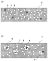
- FIG. 1 is a schematic diagram showing a state in which charge-induced hollow particles 5 (hollow particles 3 with conductive material 4 attached to the surface) and hollow particles 3 are dispersed in matrix resin 2.
- 1 is a cross-sectional view of a porous resin sheet 1 for piezoelectric elements.
- FIG. 2 shows SEM images of cross-sections of the porous resin sheet for piezoelectric elements of the present invention actually obtained and (A) and (B) are charge-induced hollow particles 5 and hollow particles 3 respectively. And the manner of dispersion is different.
- 3A shows a uniform dispersion model diagram
- FIG. 3B shows a sea-island structure model diagram. The dotted box (a, b, etc.) in (B) of FIG.
- FIG. 3 shows an island structure having a high content of charge-induced hollow particles 5 and / or hollow particles 3 and a high hollow ratio.
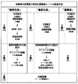
- FIG. 4 shows a flowchart of the method for producing a porous resin sheet for piezoelectric elements of the present invention in a tabular form.
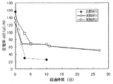
- FIG. 5 shows a graph in which the piezoelectric constant d 33 (pC / N) of the porous resin sheet for piezoelectric elements obtained in Comparative Example 1 and Examples 1 and 2 is plotted over time.
- FIG. 6 shows a graph in which the piezoelectric constant d 33 (pC / N) of the porous resin sheets for piezoelectric elements obtained in Comparative Example 2 and Example 3 is plotted over time.
- the “porous resin sheet for piezoelectric elements (hereinafter also simply referred to as“ resin sheet ”)” 1 of the present invention has “hollow particles” 3 to which “conductive substance” 4 is not attached. , And “charge-inducing hollow particles” 5 are dispersed in “matrix resin” 2.
- the “hollow particles” 3 to which the conductive substance 4 is not attached may not be present in the resin sheet 1 (not shown).
- the charge-induced hollow particles 5 are formed on the surface of the hollow particles 3 to which the conductive material 4 is not attached (the entire surface or only a part of the surface). It is attached.
- the electric charges of the “charge-inducing hollow particles” 5 and the conductive substance 4 are characterized by being higher than those of the matrix resin 2 and the hollow particles 3.
- the charge-inducing hollow particles 5 arranged along the thickness direction are close to and in contact with each other, so that a “conductive path” is easily formed. This is because it is considered that the charge easily escapes from the resin sheet surface.
- the present invention can also be said to be able to block a conductive path composed of charge-inducing hollow particles by using non-charge-inducing hollow particles 3 together and mixed with charge-inducing hollow particles 5.
- the charge retention rate of the porous resin sheet for piezoelectric elements is improved, and it is considered that high piezoelectric characteristics can be maintained over a long period of time.
- the porous resin sheet for piezoelectric elements of the present invention was actually produced, and the cross section was imaged with a scanning electron microscope [SEM].
- the scanning electron microscope used for imaging is “S-3400” manufactured by Hitachi High-Technologies Corporation, and the magnification is 100 times.
- SEM images are shown in FIGS.
- the charge-inducing hollow particles 5 and the hollow particles 3 are contained in a specific ratio, but the two particles cannot be distinguished on the image. From the SEM image in FIG. 2 (A), the particles appear to be uniformly dispersed in the resin sheet (sea structure). From the SEM image in FIG. 2 (B), the particles are clumps (islands). The islands appear to be evenly distributed.
- FIGS. 3A and 3B a uniform dispersion model and a sea-island structure model are shown in FIGS. 3A and 3B, respectively, based on the SEM image of FIG.
- FIG. 3 (A) as in FIG. 1, each particle is uniformly dispersed, whereas in FIG. 3 (B), the content of hollow particles 3 and / or charge-induced hollow particles 5 is increased.
- the island structures a and b which are high and have a high hollow ratio are contained, and the island structures a and b are uniformly dispersed.
- the island structure typically, there is a mode shown by a dotted box surrounded by a and b in FIG. 3 (B).
- the island a is a mode in which the hollow particles 3 surround the charge-induced hollow particles 5 present in the center of the island
- the island b is a mode in which the charge-induced hollow particles 5 are not in the center but are present in the outermost layer of the island. is there. It is considered that the island (particularly preferably the island a) shown in FIG. 3 (B) can behave as a pseudo large hollow particle.
- FIG. 3B The details of FIG. 3B are as follows.
- sea-island structure examples include a sea structure having a small hollow ratio (that is, a structure portion having a low content of the hollow particles 3 and / or charge-induced hollow particles 5), and an island structure having a large hollow ratio (that is, the hollow particles 3 and / or a structure part having a high content of the charge-inducing hollow particles 5).
- a high piezoelectricity is expressed in an island structure with a large hollow ratio, and the sea structure is prevented from physically approaching the polarized charges, thereby suppressing a decrease in piezoelectricity.
- a resin having a modulus of elasticity and / or conductivity different from that of the matrix resin can be used as the aggregate resin (island structure-forming resin).
- a resin sheet manufactured using a resin having a modulus of elasticity different from that of the matrix resin as an agglomerate resin undergoes non-linear deformation with respect to compressive strain during charge extraction. Deformation can be induced and thus a high piezoelectricity can be exhibited.
- the conductive material 4 is attached to the surface of the hollow particles 3 to which the conductive material 4 is not attached (not charge-induced), or at least partially or entirely. .
- the hollow particles 3 (also simply referred to as hollow particles) used in the present invention for surface coating with a conductive substance are sealed inside, that is, have a space independent from the outside.
- examples of such hollow particles include those made of glass, those made of ceramics, those made of organic polymers, and the like.
- the hollow particles made of the material having the property are preferable.
- the inside of the hollow particles 3 may be either vacuum or normal pressure depending on the use of the obtained sheet, and in the case of normal pressure, it is often filled with air or the like.
- hollow particles 3 made of glass examples include hollow particles made of soda lime glass, borosilicate glass, soda lime borosilicate glass, borosilicate soda glass, sodium silicate glass, aluminosilicate glass, and the like.
- the glass content of the hollow particles made of glass is preferably 10 to 30% by volume. If the glass content is 10% by volume or more, the hollow particles have sufficient mechanical strength, so that the hollow structure can be maintained without being broken in the processing step. The porosity can be ensured.
- the hollow particle which consists of alumina etc. is mentioned, for example.
- organic polymer either an already-expanded type or a thermally-expandable type can be applied.
- the already-expanded organic polymer include crosslinked styrene-acrylic and acrylonitrile-based polymers. Examples thereof include acrylonitrile.
- the size of the hollow particles is not particularly limited, but those having a 50% particle diameter (or cumulative median diameter) of 1 to 100 ⁇ m have high piezoelectric characteristics, high retention, and mechanical strength of the sheet itself. It is preferable in terms of securing
- the particle diameter of the hollow particles is measured based on a dynamic light scattering method.
- the porous resin sheet for piezoelectric elements can maintain a certain elasticity over a long period of time even when continuous external stress is applied to the porous resin sheet for piezoelectric elements.
- the piezoelectric characteristics of the film hardly deteriorate.
- the conductive substance 4 used in the present invention is attached to a part or all of the surface of the hollow particle 3 and has a function of holding electric charge in the porous resin sheet for piezoelectric elements.
- the conductivity of the conductive material is a material having a higher conductivity than the hollow particles 3 and the matrix resin, and more preferably the conductivity is 1.0 ⁇ 10 ⁇ 10 S / cm or more.
- the conductivity of the conductive material is measured using a double ring electrode method based on the conductivity of the single conductive material.
- the initial value of the piezoelectric constant d 33 is 110 pC / N or higher, preferably about 115 to 160 pC / N, and the piezoelectric constant d 33 after 5 days is 60 pC / N or higher, preferably 70 pC. / N or more, and the piezoelectricity d 33 after 25 days is 50 pC / N or more.
- Such a conductive substance 4 is presumed that the substance adhering to the surface of the hollow particle 3 is heat-treated in a matrix resin in an oxygen-blocking atmosphere (as a result, the substance is probably carbonized. )
- What is necessary is just to be obtained, for example, by heat-treating a surface treatment agent containing a hydrocarbon group (at a temperature equal to or higher than its thermal decomposition temperature, usually higher than the melting point of the matrix resin and lower than its decomposition temperature)
- a surface treatment agent containing the hydrocarbon group obtained by carbonization and thus subjected to heat treatment include, for example, a surfactant, a silane coupling agent, an aluminate coupling agent, and a titanate coupling agent. And may be used alone or in combination of two or more.
- the surfactant will be described in detail.
- examples of the surfactant include nonionic, zwitterionic, and cationic surfactants having a hydrocarbon group.
- the matrix resin under oxygen supply interruption conditions
- It is heated to a temperature above the decomposition temperature of the surfactant and thermally decomposed to become a conductive substance (probably decomposed into carbon, water, amorphous surfactant thermal decomposition products, etc.), and there is no environmental load.
- Inexpensive ones are desirable, and examples include those described on the Internet homepage “http://www.ecosci.jp/sa/sa.html”.
- Nonionic surfactants include fatty acid diethanolamide ⁇ R—CON (CH 2 CH 2 OH) 2 , R: an alkyl group of C1 to C20, preferably an alkyl group of about C5 to C15. ⁇ , Specifically, for example, C 11 H 23 —CON (CH 2 CH 2 OH) 2 , polyoxyethylene alkyl ether (AE) [higher alcohol type, RO (CH 2 CH 2 O) n H, R : An alkyl group of about C1-20, n: an integer of about 1-30, preferably about 5-15], specifically, for example, C 12 H 25 —O (CH 2 CH 2 O) 8 H Oxyethylene alkyl phenyl ether ⁇ (APE) (R- (C 6 H 4 ) O (CH 2 CH 2 O) n H, R: C 1-20 alkyl group, preferably about C 5-15 alkyl group, n: 1 to 30, preferably an integer of about 5 to 15) ⁇ , specifically, for example, C 9 H 19-
- Zwitterionic surfactants include alkylcarboxybetaines [betaines] ⁇ RN + (CH 3 ) 2 ⁇ CH 2 COO ⁇ , R: C1-20, preferably an alkyl group of about C5-15 ⁇ , specifically For example, C 12 H 25 —N + (CH 3 ) 2 .CH 2 COO — and the like can be mentioned.
- R an alkyl group of about C1 to C20, preferably about C5 to C15.
- ⁇ Specifically, for example, C 12 H 25 -N + ( CH 3) 3 ⁇ Cl - , etc., dialkyl dimethylammonium chloride ⁇ R 2 -N + (CH 3 ) 2 ⁇ Cl -
- R: C1 ⁇ 20 preferably an alkyl group having about C5 ⁇ 15) ⁇ , specifically, for example, C 12 H 25 -N + ( C 8 H 17) (CH 3) 2 ⁇ Cl - , etc., alkyl pyridinium chloride ⁇ R- (N + C 5 H 5 ) ⁇ Cl ⁇
- R: C1-20 preferably an alkyl group of about C5-15) ⁇ , specifically, for example, C 12 H 25- (N + C 5 H 5 ) ⁇
- nonionic surfactants are preferable in terms of suppressing charge decay after heat treatment, and polyoxyethylene alkyl ether is particularly preferable.
- a fluorosurfactant having a perfluoroalkyl group and having excellent wettability, permeability and the like can be mentioned.
- fluorine telomer alcohol F (CF 2 ) n CH 2 CH 2 OH, n: repeating unit
- nonionic surfactant for example, a nonionic surfactant of “Nonion ID-206” manufactured by Nippon Oil & Fats Co., Ltd. (thermal decomposition starting temperature under normal pressure: 150 ° C.) can be preferably used.
- fluorine-based surfactant fluorine-containing surfactant (Surflon) “S-241” (thermal decomposition start temperature under normal pressure: 220 ° C., nonionic system) manufactured by AGC Seimi Chemical Co., Ltd.
- Nonionic fluorinated surfactants or anionic fluorinated surfactants such as “Factent 251” manufactured by Neos Co., Ltd. (thermal decomposition start temperature under normal pressure: 220 ° C.) (for example, commercial products of Neos Co., Ltd., etc.) ) Can be preferably used.
- the blending amount of the surfactant is usually about 0.1 to 5% by weight with respect to 100% by weight of the hollow particles.
- the conductive substance 4 may be one or more selected from the group consisting of carbon, graphite, and platinum.
- the charge-inducing hollow particles 5 such a conductive substance 4 may be the insulating hollow particles 3 described above. It may be deposited on the surface.
- the matrix resin 2 used in the present invention is not particularly limited, and examples thereof include resins having a thermal decomposition start temperature of 150 to 450 ° C., for example, a copolymer of tetrafluoroethylene and perfluoroalkyl vinyl ether [PFA] (for example, apparent Density: 1.0 to 1.2 g / ml (according to ASTM D2116)), tetrafluoroethylene and hexafluoropropylene copolymer [FEP] (for example, apparent density: 1.0 to 1.2 g / ml), poly Chlorotrifluoroethylene [PCTFE] (eg apparent density: 0.9 to 1.2 g / ml), copolymer of tetrafluoroethylene and ethylene [ETFE] (eg apparent density: 1.0 to 1.2 g / ml) ml), polyvinylidene fluoride [PVdF], polyvinyl fluoride
- thermoplastic resin from the viewpoint of easy work of uniformly dispersing the hollow particles 3 and the charge-inducing hollow particles 5.
- the matrix resin is preferably a material that is more separated from the hollow particles that are easily charged positively and in a charge train, for example, a fluorine-containing resin or an imide resin, from the viewpoint of charging characteristics.
- the “material separated by the charged column” means the Textile Society edition, “Fiber Handbook (raw material edition)”, Maruzen (1968), Hidetoshi Tsuchida, Taku Shinohara, polymer, 16,347. (1967) means a material such as a fluorine-containing resin in which the charged column is positioned on the minus side of the glass hollow particles based on the charged column table disclosed in (1967).
- the matrix resin is preferably a resin having a high melting temperature and a high thermal decomposition starting temperature from the viewpoint of heat resistance, for example, a fluorine-containing resin or an imide resin.
- the surface treatment agent containing a hydrocarbon group is heat-treated to have a desired conductivity (perhaps carbonized).
- Such a matrix resin 2 preferably has a thermal decomposition start temperature in the range of 150 ° C. to 450 ° C., more preferably a thermal decomposition start temperature in the range of 300 ° C.
- thermo decomposition Fluorine-containing resins such as FEP (pyrolysis start temperature: about 400 ° C), ETFE (pyrolysis start temperature: about 360 ° C), PCTFE (pyrolysis start temperature: about 340 ° C)
- an imide resin such as polyimide (thermal decomposition start temperature: about 400 ° C.), bismaleimide (thermal decomposition start temperature: about 400 ° C.), or the like.
- the thermal decomposition start temperature (carbonization temperature) at which the surface treatment agent containing a hydrocarbon group is heat-treated and exhibits conductivity more specifically, a temperature that is usually 50 ° C. lower than the thermal decomposition temperature of the matrix resin 2, Preferably, the temperature is lower by 100 ° C. or more from the viewpoint of ease of heat treatment temperature control.
- the porous resin sheet 1 for piezoelectric elements is excellent in heat resistance and weather resistance, and particularly excellent in temporal stability of piezoelectric characteristics at a high temperature of 80 ° C. or higher. preferable.
- any of the “pre-carbonization method”, “post-carbonization method” and “evaporation method” can be adopted as the method for producing the porous resin sheet 1 for piezoelectric elements of the present invention.
- the sea-island structure in the porous resin sheet for piezoelectric elements of the present invention it can be produced by further applying a “two-stage dispersion method” to the above production method.
- Step (3) A step of injecting electric charge into the sheet by subjecting the sheet obtained in the step (2) to polarization treatment.
- This pre-carbonization method can form the charge-induced hollow particles 5 in the step (1a).
- a surfactant containing a hydrocarbon group is treated with an appropriate solvent (for example, a method of diluting with a surfactant and immersing hollow particles in the surfactant solution can be used.
- the amount of the surfactant necessary for coating the hollow particles in the solvent depends on the type of the surfactant, but is preferably less than 5%, more preferably based on the weight of the hollow particles. Is about 0.1 to 1.0%.
- the amount of the surfactant exceeds 5% with respect to the weight of the hollow particles, there is a possibility that electric charges can easily escape from the porous resin sheet for piezoelectric elements. On the other hand, if it is less than 0.1%, it may be difficult to form a conductive material on the hollow particles. Thus, when the surface treating agent containing a hydrocarbon group is used, a conductive material can be efficiently formed in a small amount.
- the amount of the surfactant to be added to the solvent is not particularly limited as long as the surface treatment agent-containing liquid can be satisfactorily adhered to the surface of the hollow particle 3.
- the heat treatment of the hollow particles includes, for example, treatment at 250 to 400 ° C. for 10 to 120 minutes while blocking oxygen.
- the hollow particles 3 are imparted with electrical conductivity to the surface because at least part (preferably all) of the hydrocarbon group part of the surface treatment agent containing hydrocarbon groups is probably It is considered that the conductive material is formed on at least a part (preferably all) of the surface of the hollow particles.
- the charge-inducing hollow particles obtained in the step (1a) are kneaded with the matrix resin and then molded to obtain a resin sheet.
- This resin sheet can be produced by a conventionally known method.
- the matrix resin is a thermoplastic resin
- the charge-inducing hollow particles and the matrix resin are formed by a molding machine such as a single-screw or twin-screw extruder. After being melt-kneaded, it is molded into a sheet by using, for example, a pressure molding machine or a T die.
- the molding temperature is usually about the same as the melting temperature of the matrix resin.
- an elastic control auxiliary agent eg, silicon resin fine particles, styrene resin fine particles, acrylic resin fine particles, etc.
- an elastic control auxiliary agent eg, silicon resin fine particles, styrene resin fine particles, acrylic resin fine particles, etc.
- step (3) by applying a polarization treatment to the sheet obtained in the step (2), charges can be injected into the sheet. More specifically, charges are injected from the surface of the sheet molded in step (2) by a polarization process such as corona discharge.
- the injected charge is concentrated on the shell part of the charge-inducing hollow particles, and induces polarization in the hollow structure.
- a part of the induced charge is considered to hold the charge at the interface between the charge-induced hollow particles and the matrix resin.
- the internally polarized sheet can take out electric charges through the front and back surfaces of the sheet by applying a compressive load in the sheet thickness direction. That is, charge transfer occurs with respect to the external load (electric circuit), and an electromotive force is obtained.
- the surface treatment agent containing the hydrocarbon group attached to at least a part of the particle is made conductive (possibly carbonized), and the conductive substance is attached to at least a part of the surface of the hollow particle.
- step (1b) at least a part (preferably all) of the surface of the hollow particles was coated with a surface treatment agent containing a hydrocarbon group, and then obtained as step (2 ′) in step (1b).
- the hollow particles having a surface treatment agent containing a hydrocarbon group attached to at least a part (preferably all) of the surface are kneaded with a matrix resin, and then molded into a sheet, and at least a part of the surface of the hollow particles (preferably The surface treatment agent adhering to (all) is subjected to thermal decomposition by being kneaded in an oxygen non-supplying atmosphere and possibly carbonized to form a conductive substance on the surface of the hollow particles.
- Step (1b) is the same as the case of the coating in the step (1a) described above.
- melt-kneading conditions and molding conditions in the step (2 ′) are as follows.
- the melting temperature is preferably 10 to 50 ° C. higher than the melting point of the matrix resin.
- the melting time is preferably 1 to 30 minutes.
- the heating temperature at the time of molding is preferably a temperature that is 10 to 50 ° C. higher than the melt kneading temperature and is lower than the thermal decomposition start temperature of the matrix resin.
- the heating time is preferably 10 to 120 minutes.
- the case where FEP (melting point: 260 ° C., thermal decomposition start temperature: 400 ° C.), for example, is used as the matrix resin will be described as an example as follows.
- a hollow particle having a surface attached with a surface treatment agent containing a hydrocarbon group and FEP are melt-kneaded with a molding machine such as a single-screw or twin-screw extruder (usually at 300 to 310 ° C. for about 30 minutes).
- the matrix resin is thermally decomposed at a temperature higher than the melt kneading temperature (eg, about 10 to 50 ° C.). After heating at 350 ° C. below the starting temperature for 10 to 120 minutes, pressurize to a desired shape under air cooling conditions (eg, normal temperature) at 40 to 150 kgf / cm 2 or under heating.
- a temperature higher than the melt kneading temperature eg, about 10 to 50 ° C.
- the hydrocarbon group portion of the surface treatment agent containing the hydrocarbon group covering the surface of the hollow particles is at least a part thereof It is considered that (preferably all) is carbonized due to thermal decomposition when heated at the above high temperature in an oxygen non-supplying atmosphere. It seems that hollow particles will be obtained.
- Process (3) is as described above.
- the charge-induced hollow particles can be formed by evaporating a conductive material on at least a part (preferably all) of the surface of the hollow particles.
- a conductive material preferably all of the surface of the hollow particles.
- Graphite, platinum and the like and may be used alone or in combination of two or more.
- a conventionally known vapor deposition method can be used.
- a conductive material may be attached to the surface of the hollow particles by plating.
- an island structure portion (agglomerates having a high content of hollow particles 3 and / or charge-induced hollow particles 5, preferably hollow particles 3 and charge-induced hollows, as indicated by symbols a and b)
- the porous resin sheet for piezoelectric elements of the present invention in which the aggregates having a high content of particles 5 are uniformly dispersed can be produced as follows.
- a porous resin sheet for a piezoelectric element of the present invention having a sea-island structure can be produced in the same manner as any of the pre-carbonization method, post-carbonization method, and vapor deposition method except that is used.
- an aggregate is prepared by melting and kneading a resin (aggregate resin, that is, an island structure forming resin) having a higher viscosity than the matrix resin, and charge-induced hollow particles and / or hollow particles.
- the porous resin sheet for piezoelectric elements of the present invention having a sea-island structure can be produced.
- the agglomerated structure is difficult to dissolve even if the agglomerates are diluted with a molten matrix resin, and a resin sheet having the desired island structure remains. Obtainable.
- the hollowness of the island structure contained in the resin sheet (that is, the aggregate in which the content of the hollow particles 3 and / or the charge-induced hollow particles 5 is higher than that of the sea structure portion) is 30 to 80 volumes. % Is preferable in that sufficient electric charge is stored in the sheet and the piezoelectricity is increased, and the sea structure (that is, a structure in which the content of the hollow particles 3 and / or the charge-induced hollow particles 5 is lower than that of the island structure portion)
- the porosity of the part is preferably from 0 to 10% by volume because the distance between the holes is maintained, and the charges polarized in the island structure can be maintained over a long period of time.
- the overall sea-island structure is preferably 10 to 70% by volume, and preferably 15 to 60% by volume, in terms of the initial value of piezoelectricity, its retainability, and long-term mechanical strength.
- the sea structure, the island structure, and the overall hollow ratio of the sea-island structure are calculated by the following formula based on the amount of material used for creating the sheet.
- Hollow ratio (%) ((volume A ⁇ volume B) / volume A) ⁇ 100, Volume A: Volume calculated from material weight and material specific gravity (true specific gravity).
- Volume B Volume calculated from material weight and specific gravity excluding the hollow structure.
- the hollow ratio of the entire sea-island structure is less than 15% by volume, sufficient electric charge cannot be stored, and there may be a case where a sufficient piezoelectric ratio as a piezoelectric material cannot be secured.
- the hollowness exceeds 60% by volume, the distance between the island structures is substantially close, so the effect of forming the sea-island structure is reduced, that is, the purpose of enhancing the retention of piezoelectric characteristics cannot be achieved. There is a case.
- the size of the island structure is preferably about 0.1 to 1.0 times the thickness of the sheet molding.
- the resin used for the preparation of the aggregate is not particularly limited as long as it has a higher viscosity than the matrix resin during kneading and molding, and examples thereof include the resins exemplified above as the matrix resin. It is done. Among these, it is preferable to use a resin having an elastic modulus different from that of the matrix resin as the resin for aggregates (resin for island structure creation).
- the difference in elastic modulus between the resin for aggregates and the matrix resin is preferably 10 MPa or more from the viewpoint that the initial value of piezoelectricity is high and the retention rate can be increased.
- the viscosity of the resin for aggregates is preferably 10 times or more the viscosity of the matrix resin at the kneading temperature.
- the elastic modulus of these resins can be measured based on the following method according to JIS K7210.
- the resin as a raw material is formed into a 3 cm ⁇ 3 cm ⁇ 2 mm sheet by a known method, and the obtained sheet is tested with a universal compression tester (manufactured by Minebea Co., Ltd .; “Technograph TG-50kN”) at a test speed of 5 mm / min. Then, a compressive stress-strain curve is created from the measured value and calculated based on this.
- a universal compression tester manufactured by Minebea Co., Ltd .; “Technograph TG-50kN”
- a resin sheet manufactured using a resin having a modulus of elasticity different from that of a matrix resin as an agglomerate resin causes non-linear deformation with respect to compressive strain. Therefore, deformation of the entire resin sheet can be induced by minute stress. Therefore, a high piezoelectricity can be exhibited when external stress is applied.
- a fluorine-containing resin or an imide resin as the aggregate resin and the matrix resin from the viewpoints of heat resistance and weather resistance of the porous resin sheet for piezoelectric elements.
- a layer composed of the aggregate can be further formed on the surface of the aggregate prepared as described above, and this method is referred to as “three-stage dispersion method” in the present invention.
- the three-stage dispersion method is preferable because it is easy to form the island structure a in FIG.
- Example 1 Manufacture of porous resin sheet for piezoelectric elements
- composition is soda-lime borosilicate glass, 50% particle size is 16 ⁇ m, and glass amount (calculated value) is 24 (volume) 1% by weight of nonionic surfactant based on the weight of the hollow particles (NON-ID-ID manufactured by NOF Corporation), with a conductivity of 1.0 ⁇ 10 ⁇ 13 S / cm. 206; polyoxyethylene isodecyl ether: thermal decomposition onset temperature: 150 ° C.), the surfaces of the hollow particles were coated.
- the hollow particles were immersed and coated in a solution obtained by diluting a predetermined amount of a surfactant 50 times with methyl alcohol.
- the coating with the nonionic surfactant on the surface of the hollow particles was confirmed using SEM.
- This nonionic surfactant (Nonion ID-206) does not contain a solvent.
- FEP copolymer of tetrafluoroethylene and hexafluoropropylene; NEOFLON TM FEP “NP-101” manufactured by Daikin Industries, Ltd .; Conductivity: 1.0 ⁇ 10 ⁇ 16 S / cm; MFR: 24 g / 10 min (ASTMD2116); Melting point: 255 ° C. (ASTMD2116); Apparent density 1.21 g / ml (JISK6891)) 100 g and 300-310 ° C. After being melt-kneaded for 30 minutes, the sample was compressed into a sheet (heated at 350 ° C. for 40 minutes and then pressurized at 60 kgf / cm 2 under air cooling conditions) to prepare a sample sheet having a thickness of 0.5 mm.
- the hollowness of the sample sheet was 30% by volume.
- the hollow ratio was calculated by the following method.
- Volume B Volume calculated from material weight and specific gravity excluding the hollow structure.
- the true specific gravity of the hollow particles is 0.6 g / cm 3 (see Sumitomo 3M Co., Ltd., product catalog “Glass Bubbles-High Functional Additives”), and the specific gravity of the hollow particles excluding the hollow structure is 2.5 g / cm 3. 3
- the specific gravity of FEP was calculated as 2.1 g / cm 3 .
- the surfactant adhering to the surface of the hollow particles by the sheet preparation process is heated at a melting temperature such as FEP, which is a temperature exceeding the decomposition temperature, so that the conductivity is 1.0 ⁇ 10 ⁇ 10 S / cm. It was a conductive substance. From this, it is considered that a part or all of the surfactant adhering to the surface of the hollow particles by the sheet preparation process is carbonized (hereinafter, abbreviated as “carbonized layer” in some cases). ).
- the conductivity of the carbonized layer was measured using a resistivity meter (digital) on a carbonized layer prepared by heating a surfactant coating layer on a glass substrate at 300 ° C. under reduced pressure (oxygen-blocking environment) for a predetermined time.
- a super insulation / micro ammeter DSM-8104 manufactured by Hioki Electric Co., Ltd. was used, and the measurement was performed based on the double ring electrode method.
- This sample sheet was subjected to a polarization treatment by corona discharge for 3 minutes at room temperature with a distance of 12.5 mm between electrodes, a voltage between electrodes of 3 kV using a corona discharge device manufactured by Kasuga Electric Co., Ltd., and a porous resin sheet for piezoelectric elements Manufactured.
- a constant AC acceleration ⁇ (frequency: 90 to 300 Hz, size: 2 to 10 m / s 2 ) is given in the thickness direction of the sample for evaluation under the condition of room temperature (20 ° C) and humidity of 20%.
- the response charge at that time was measured, and the initial piezoelectric constant d 33 (pC / N) was determined (this time is 0 day).
- Example 2 In Example 1, a porous resin sheet for a piezoelectric element was produced in the same manner as in Example 1 except that the nonionic surfactant used was changed to 0.5% by weight based on the weight of the hollow particles. Then, the piezoelectric performance was evaluated in the same manner as in Example 1, and the results are shown in Table 1 and FIG.
- Example 1 In Example 1, the nonionic surfactant used with respect to the weight of the hollow particles was changed to 0% (that is, the hollow particles were not coated with the surfactant). A porous resin sheet was produced. Then, the piezoelectric performance was evaluated in the same manner as in Example 1, and the results are shown in Table 1 and FIG.
- d 33 of the porous resin sheet for piezoelectric elements produced in the examples is maintained at 60 pC / N or more even after 5 days, and the conductive material is on the surface. It can be seen that the retention of the piezoelectric characteristics is high as compared with Comparative Example 1 using hollow particles that are not attached.
- Example 3 Evaluation of heat resistance of porous resin sheet for piezoelectric elements
- the porous resin sheet for piezoelectric elements produced in Example 2 was subjected to heat treatment by being allowed to stand for 100 hours in an electric furnace maintained at 80 ° C. after evaluation in Example 2 after 5 days. Thereafter, the sheet was taken out from the electric furnace, cooled to room temperature, and then evaluated for piezoelectric characteristics in the same manner as in Example 1 (corresponding to measurement after 9 days from the date of manufacture).
- d 33 of the porous resin sheet for piezoelectric elements after the heat treatment was 61 pC / N, and the same characteristics as the sheet before the heat treatment were maintained.
- the porous resin sheet for piezoelectric elements of the present invention has heat resistance that does not deactivate the piezoelectric characteristics even in a high temperature environment such as 80 ° C.
- Example 4 ⁇ Manufacture of island structure pellets> As hollow particles, hollow glass beads (Potters Barotini, 60P18, conductivity: 1.0 ⁇ 10 ⁇ 14 S / cm) (composition is borosilicate glass, particle diameter is 16 ⁇ m, true specific gravity is 0.6) g / cm 3 , specific gravity assuming hollow particles as solid is 2.5 g / cm 3 , glass amount (calculated value) is 24 (volume ratio%)), and weight of hollow particles (100 wt%) On the other hand, the surface of the hollow particles was coated with 1% by weight of a nonionic surfactant (Nonchi ID-206 manufactured by NOF Corporation; thermal decomposition start temperature: 150 ° C.).
- a nonionic surfactant Nonchi ID-206 manufactured by NOF Corporation; thermal decomposition start temperature: 150 ° C.
- the hollow particles were immersed and coated in a solution obtained by diluting a predetermined amount of surfactant with methyl alcohol 50 times by weight at normal temperature and normal pressure.
- This nonionic surfactant (Nonion ID-206) does not contain a solvent.
- NEOFLON FEP manufactured by Daikin Industries, model number: NP101, MFR: 24 g / 10 min (according to ASTM D2116), viscosity at 300 ° C: 1.0 ⁇ 10 6 poise, melting point 255 ° C (according to ASTM D2116), apparent 29.0 g of density 1.21 g / ml (JIS K 6891 compliant), specific gravity: 2.1 g / cm 3 , conductivity: 1.0 ⁇ 10 ⁇ 16 S / cm 2) is kneaded at 300 ° C. for 5 minutes using a lab plast mill, Further, 23.0 g of the island structure pellets were added as an island structure, and then kneaded at 300 ° C. for 10 minutes to prepare sea island structure pellets.
- the material ratio was calculated from the weight and density of each material and the amount of hollow particle glass.
- sea-island structure pellets were placed in a mold, heated at 350 ° C./1 h, and then compressed at 3 mm MPa under air cooling to form a sample sheet.
- the surfactant adhering to the surface of the hollow particles was a conductive substance having a conductivity of 1.0 ⁇ 10 ⁇ 10 S / cm.
- the conductivity is measured with a resistivity meter (digital super-insulation / digital super-insulation) on a carbonized layer prepared by heating a surfactant coating layer on a glass substrate at 300 ° C. under reduced pressure (oxygen-blocking environment) for a predetermined time.
- the measurement was performed based on the double ring electrode method using a microammeter DSM-8104 (manufactured by Hioki Electric Co., Ltd.).
- Porous resin sheet for piezoelectric elements the structure is the same before and after the polarization treatment in step (3)
- 2 Matrix resin
- 3 hollow particles
- 4 conductive material
- 5 charge-induced hollow particles
- a, b ... island structure (agglomerates having a high content of hollow particles 3 and / or charge-induced hollow particles 5
Abstract
[課題] 広い使用温度域で長期に亘って高い圧電特性を維持することができる、耐環境性、耐熱性に優れた圧電素子用多孔質樹脂シートおよびその製造方法を提供すること。 [解決手段] 本発明の圧電素子用多孔質樹脂シートは、少なくとも電荷誘起性中空粒子がマトリックス樹脂に分散してなり、該電荷誘起性中空粒子は、中空粒子の表面の少なくとも一部に導電性物質が付着してなり、該導電性物質は、中空粒子およびマトリックス樹脂よりも導電率が高い物質であることを特徴とする。
Description
本発明は、導電性物質を表面に有する中空粒子がマトリックス樹脂中に分散してなる圧電素子用多孔質樹脂シートおよびその製造方法に関する。
従来、高分子材料を利用した圧電材料は、分極構造を得るために、発泡、延伸などの方法で多孔質構造とすることや分極しやすい結晶構造とすることが検討されてきた。特に、高分子材料を多孔質構造にした場合には、高い圧電特性を示すことが知られており、例えば特許文献1には、ポリプロピレン等の有機高分子にガラス中空粒子を配合してなる成形体に電荷を注入してなるエレクトレットが開示されている。
しかしながら、特許文献1のように高分子材料を多孔質構造とすることによって、高分子材料内部に形成された空孔部分に電荷が保持されやすくなり高い圧電特性を示すが、経時による特性低下が著しく、また、高温での特性低下も大きい。また、特許文献1に開示されているエレクトレットは、短期的には良好な圧電特性を発揮することができるが、ガラス中空粒子をそのまま用いても、長期間にわたって圧電特性を維持することができないことがわかった。
さらに、耐熱性および圧電特性の経時安定性に優れた圧電材料の例として、特許文献2には、平均最大垂直弦長が1~40μmかつ平均アスペクト比が0.7~4.0の気泡を有し、体積空孔率が20~75%であり、樹脂成分の比誘電率よりも高い比誘電率を有するセラミックス粒子を含有する圧電・焦電素子用多孔質樹脂シートが開示されている。しかしながら、圧電・焦電素子用多孔質樹脂シートの製造過程で用いる相分離化剤を除去するのに溶媒抽出工程が必要とされるため、工業的な実用化が困難である。
また、多孔質系有機圧電材料における電荷減衰のメカニズムはいくつか想定されている。その一つとして、多孔質構造に保持されている分極した電荷同士が、有機材料の熱運動や物理的な変形によって接近し互いに打ち消しあうこと、また、他の場合としては、偶発的な導電経路の形成によって外部環境と接続し、電荷自体が失われることが挙げられる。
多孔質系有機圧電材料の特性としては、圧電率の初期値とその保持性が重要である。圧電率の初期値を高める方法としては、多孔構造の空孔率を大きくして多くの分極した電荷を保持し、さらに、変形しやすい構造とすることが挙げられる。一方、保持性を高めるには、空孔部分に保持した分極した電荷同士が電気的に短絡しない距離を保持することが重要である。しかしながら、圧電率を高めるために空孔率を大きくすることは、同じ体積では電荷を保持している空孔部同士の距離を小さくすることにつながり保持性を低下させることとなり、両者は背反条件であった。
このような状況下、高い空孔率を保ちつつ、空孔部同士の距離を大きく保つ構造を有し、且つ圧電率の初期値とその保持性に優れた圧電素子用多孔質樹脂シートの開発が望まれていた。
本発明は、広い使用温度域で長期に亘って高い圧電特性を維持することができる、耐環境性(極端な温度や湿度の変化、衝撃や振動などの過酷な環境に対する耐性)、耐熱性に優れた圧電素子用多孔質樹脂シートおよびその製造方法を提供することを目的とする。
そこで本発明者らは、高分子材料を利用した圧電材料において、有機高分子からなるマトリックス樹脂に中空粒子の表面の少なくとも一部に導電性物質が付着してなる電荷誘起性中空粒子を配合すると、長期に亘って高い圧電特性を維持できることを見出し、本発明の完成に至った。
すなわち、本発明の圧電素子用多孔質樹脂シートは、少なくとも電荷誘起性中空粒子がマトリックス樹脂に分散してなり、該電荷誘起性中空粒子は、中空粒子の表面の少なくとも一部に導電性物質が付着してなり、該導電性物質は、中空粒子およびマトリックス樹脂よりも導電率が高い物質であることが好ましい。
さらに、上記の導電性物質は、中空粒子の表面の少なくとも一部に付着した、炭化水素基を有する物質の一部または全部を、該炭化水素基が酸素遮断条件下であるマトリックス樹脂中で熱分解させることで導電性を生じさせるような条件、例えば、マトリックス樹脂の熱分解開始温度より低い、100~350℃の温度で10分間~6時間程度、減圧~加圧下(例:0.1Pa~10MPa)に、加熱処理することによって得られる。
その結果、炭化水素基を有する物質は、導電性が付与されていることからおそらく酸素遮断条件下で熱分解され炭化したものと想定される。なお、炭化水素基を有する物質の酸素遮断条件下での熱分解開始温度は、マトリックス樹脂の熱分解開始温度未満、好ましくは、マトリックス樹脂の熱分解開始温度より、通常50~300℃、好ましくは100~250℃程度低いことが、得られるシートの性能(例:圧電率の初期値が高く、かつ、圧電率の経時的低下も少ないなど)の点で好ましい。
該炭化水素基を有する物質としては、炭化水素基を含む表面処理剤であり、該表面処理剤が、界面活性剤、シランカップリング剤、アルミネート系カップリング剤およびチタネート系カップリング剤からなる群から選択される一種以上であることが好ましい。なお、上記炭化水素基を有する物質としては、常圧下での熱分解開始温度が、通常100~300℃、好ましくは150~250℃のものが、操作性などの点で望ましい。
また、上記の導電性物質は、上記中空粒子の表面の少なくとも一部に導電材料を蒸着して得られ、上記導電材料が、カーボン、グラファイト、白金、金およびITO(酸化インジウムスズ)からなる群から選択される一種以上であることが好ましい。
上記中空粒子は、ガラス、セラミックスまたは有機系高分子であることが好ましい。
また、上記マトリックス樹脂は、帯電特性の観点から、プラスに帯電しやすい該中空粒子と、帯電列でより離れた材料であることが好ましく、例えば含フッ素系樹脂、イミド系樹脂、ポリオレフィン系樹脂、ポリアミド系樹脂などが好ましい。また、耐熱特性の観点から、含フッ素系樹脂、イミド系樹脂が好ましい。
本発明は、広い使用温度域で長期に亘って高い圧電特性を維持することができる、耐環境性、耐熱性に優れた圧電素子用多孔質樹脂シートおよびその製造方法を提供することができる。
本発明によると、圧電素子用多孔質樹脂シートに中空粒子の表面の少なくとも一部に導電性物質が付着してなる電荷誘起性中空粒子が分散されていることで、分極処理において電界が電荷誘起性中空粒子表層の導電性物質とマトリックス樹脂および/または中空粒子との界面に集中し、さらに電荷が中空部分に効率的に導入されることによって高い圧電率を長期に亘って保持することができる。
また、本発明の圧電素子用多孔質樹脂シートは、圧電率を高める機能を有する中空率が大きい島構造と、分極された物理的な接近を妨げて圧電率の低下を抑制する中空率が小さい海構造を有するため、高い圧電率と長期圧電特性維持を両立することができる。
また、本発明の圧電素子用多孔質樹脂シートは、中空率が大きい島構造を構成する樹脂と、中空率が小さい海構造を構成する樹脂との弾性率が異なるため、圧縮歪に対して非線形の変形を誘起し、高い圧電率を示すことができる。
また、本発明によると、中空粒子は独立気孔構造であるため、圧電素子用多孔質樹脂シートに連続的な外部応力が加わっても長期間に亘って一定の弾性を保持することができ、さらに圧電特性の変化がほとんどない。
本発明の圧電素子用多孔質樹脂シートにおいて、マトリックス樹脂として、含フッ素系樹脂、イミド系樹脂を用いると、耐熱性、耐候性に優れた圧電素子用多孔質樹脂シートを提供することができる。
図1に示すように、本発明の「圧電素子用多孔質樹脂シート(以下、単に「樹脂シート」ともいう。)」1は、「導電性物質」4が付着していない「中空粒子」3、および「電荷誘起性中空粒子」5が「マトリックス樹脂」2中に分散してなっている。
本発明では、導電性物質4が付着していない「中空粒子」3が樹脂シート1中に存在しなくてもよい(図示せず)。
この電荷誘起性中空粒子5は、導電性物質4が付着していない上記中空粒子3の表面(表面の全部であっても、その一部だけであってもよい。)に導電性物質4が付着したものである。「電荷誘起性中空粒子」5、導電性物質4の導電率は、マトリックス樹脂2および中空粒子3の導電率より高いことを特徴とする。
仮に、圧電素子用多孔質樹脂シート1中に、導電性物質4が付着していない(電荷誘起性ではない)中空粒子3が一切存在せず、図1における中空粒子3をすべて電荷誘起性中空粒子5に置換した場合(総個数では同じ)を想定すると、すなわち、電荷誘起性中空粒子5のみが分散しているとすると(図示せず)、前記中空粒子3と前記電荷誘起性中空粒子5の両者が分散している本発明の圧電素子用多孔質樹脂シート1と比べて、圧電特性の初期値(経過時間=0日)は多少向上するが、圧電特性の経時的な減衰が顕著であると推測される。それは、電荷誘起性中空粒子5のみが分散している樹脂シート中、その厚さ方向に沿って並んでいる電荷誘起性中空粒子5が互いに近接・接触することにより「導電パス」が形成され易くなるため、樹脂シート表面から電荷が逃げやすくなると考えられるからである。本発明は、電荷誘起性ではない中空粒子3を電荷誘起性中空粒子5と併用・混在させることによって、電荷誘起性中空粒子からなる導電パスを遮断することができるものとも言える。
導電パスが遮断されると、圧電素子用多孔質樹脂シートの電荷保持率が向上するため、長期に亘って高い圧電特性を維持することができると考えられる。
本発明の圧電素子用多孔質樹脂シートを実際に製造し、その断面を走査型電子顕微鏡〔SEM〕により撮像した。なお、撮像に使用した走査型電子顕微鏡は、(株)日立ハイテクノロジーズ製「S-3400」であり、倍率は100倍である。これらのSEM画像を、図2の(A),(B)に示す。いずれの樹脂シートにも、電荷誘起性中空粒子5と中空粒子3とが特定の割合で含有されているが、両者の粒子を画像上区別することはできない。図2(A)のSEM画像から、それら粒子が該樹脂シート(海構造)中に均一に分散しているように見え、図2(B)のSEM画像からは、それら粒子が塊(島)状に集まり、各島が均一に分散しているように見える。
本発明につき、さらに理解を容易にするために、図2のSEM画像に基き、均一分散モデルと海島構造モデルとを、それぞれ図3の(A),(B)に示す。図3(A)では、図1と同様、それぞれの粒子が均一に分散しているのに対して、図3(B)では、中空粒子3および/または電荷誘起性中空粒子5の含有率が高く、中空率が大きい島構造a,bを含有し、それら島構造部a,bが均一に分散している。
島構造として、典型的には、図3(B)中のaおよびbの点線の囲みで示される態様が挙げられる。島aは、島の中心に存在する電荷誘起性中空粒子5を中空粒子3が取り囲む態様であり、島bは、電荷誘起性中空粒子5が中心にはなく島の最外層に存在する態様である。図3(B)に示す島(特に好ましくは島a)は、擬似的に大きな中空粒子として振る舞うことができると考えられる。
図3(B)における隣接する島(大きな中空粒子)間の距離は、図3(A)における隣接する中空粒子間の距離より長いため、電荷誘起性中空粒子5から樹脂シート表面へ通じる導電パスが形成されにくく、特に島aにおいては、電荷誘起性中空粒子5の周囲に導電パスを遮断する中空粒子3が存在するために特に導電パスが形成されにくく、圧電素子用多孔質樹脂シートの電荷保持率が向上するため、図3(B)の海島構造モデルは、図3(A)の均一分散モデルより圧電特性の経時的な減衰が緩慢となり、長期に亘って高い圧電特性を維持することができると推察される。
図3の(B)についてさらに詳しく述べると以下のとおりである。
海島構造の他の一例としては、中空率が小さい海構造(すなわち、中空粒子3および/または電荷誘起性中空粒子5の含有率が低い構造部)、中空率が大きい島構造(すなわち、中空粒子3および/または電荷誘起性中空粒子5の含有率が高い構造部)からなる海島構造から構成されるものが挙げられる。中空率が大きい島構造で高い圧電率を発現させ、海構造が分極された電荷同士の物理的な接近を妨げ、圧電率の低下を抑制する。これら海構造と島構造とからなる海島構造がシート内部に分散して存在することにより、すなわち中空粒子および/または電荷誘起性中空粒子5がシート内部にて不均一に分散して存在することにより、高い圧電率及び長期圧電特性維持を両立させることができると推察される。
また、海島構造を後述する二段階分散により製造する場合、凝集体用樹脂(島構造作成用樹脂)としてマトリックス樹脂と弾性率および/または導電率の異なる樹脂を用いることができる。
凝集体用樹脂として、マトリックス樹脂と弾性率が異なる樹脂を用いて製造された樹脂シートは、電荷の取り出しの際の圧縮歪に対して非線形の変形を起こすため、微小な応力によって樹脂シート全体の変形を誘起することができ、よって高い圧電率を示すことができる。
(電荷誘起性中空粒子5)
本発明で用いる電荷誘起性中空粒子5は、導電性物質4が付着していない(電荷誘起性ではない)中空粒子3の表面に、導電性物質4が少なくとも一部または全面に付着している。
本発明で用いる電荷誘起性中空粒子5は、導電性物質4が付着していない(電荷誘起性ではない)中空粒子3の表面に、導電性物質4が少なくとも一部または全面に付着している。
(中空粒子3)
本発明で用いられる、導電性物質による表面被覆に供される中空粒子3(単に、中空粒子ともいう。)は、その内部が密閉状態、すなわち外部から独立した空間を有するものであり、マトリックス樹脂と溶融混練する際に溶融・破壊されないものであればよく、このような中空粒子としては、例えば、ガラスからなるもの、その他セラミックスからなるものや有機系高分子からなるもの等が挙げられ、絶縁性の材料からなる中空粒子が好ましい。中空粒子3の内部は、得られるシートの用途に応じて真空、常圧のいずれでもよく、常圧の場合は空気等で満たされることが多い。
本発明で用いられる、導電性物質による表面被覆に供される中空粒子3(単に、中空粒子ともいう。)は、その内部が密閉状態、すなわち外部から独立した空間を有するものであり、マトリックス樹脂と溶融混練する際に溶融・破壊されないものであればよく、このような中空粒子としては、例えば、ガラスからなるもの、その他セラミックスからなるものや有機系高分子からなるもの等が挙げられ、絶縁性の材料からなる中空粒子が好ましい。中空粒子3の内部は、得られるシートの用途に応じて真空、常圧のいずれでもよく、常圧の場合は空気等で満たされることが多い。
ガラスからなる中空粒子3としては、例えばソーダ石灰ガラス、ほうケイ酸ガラス、ソーダ石灰ほうケイ酸ガラス、ほうケイ酸ソーダガラス、ケイ酸ソーダガラス、アルミノケイ酸ガラスなどからなる中空粒子が挙げられる。
前記ガラスからなる中空粒子のガラス含量は、10~30体積%であるものが好ましい。前記ガラス含量が10体積%以上であれば、中空粒子が十分な機械強度を有するため、加工工程で破壊されることなく中空構造を維持することができ、30体積%以下であれば、十分な空隙率を確保することができる。
セラミックスからなるものとしては、例えばアルミナなどからなる中空粒子が挙げられる。
有機高分子からなるものとしては、既膨張型、熱膨張型のいずれも適用可能であり、既膨張型有機高分子としては、例えば架橋スチレンアクリル系、アクリロニトリル系などが、熱膨張型有機高分子としては、アクリロニトリル系などが挙げられる。
中空粒子の大きさは、特に限定されるものではないが、その50%粒子径(または累積中位径)が1~100μmであるものが高い圧電特性と高い保持率およびシート自体の機械的強度を担保するという点で好ましい。中空粒子の粒子径は、動的光散乱法に基づいて測定される。
中空粒子は独立気孔構造であるため、圧電素子用多孔質樹脂シートに連続的な外部応力が加わっても長期間に亘って一定の弾性を保持することができるとともに、圧電素子用多孔質樹脂シートの圧電特性はほとんど低下しない。
(導電性物質4)
本発明で用いる導電性物質4は、中空粒子3の表面の一部または全部に付着しており、圧電素子用多孔質樹脂シートにおいて電荷を保持する作用を有するものである。この導電性物質の導電率は、中空粒子3およびマトリックス樹脂よりも導電率が高い物質であり、より好ましくは、導電率が1.0×10⁻¹⁰S/cm以上である。導電性物質の導電率は、導電性物質単体の導電率に基づいて、二重リング電極法を用いて測定される。
本発明で用いる導電性物質4は、中空粒子3の表面の一部または全部に付着しており、圧電素子用多孔質樹脂シートにおいて電荷を保持する作用を有するものである。この導電性物質の導電率は、中空粒子3およびマトリックス樹脂よりも導電率が高い物質であり、より好ましくは、導電率が1.0×10⁻¹⁰S/cm以上である。導電性物質の導電率は、導電性物質単体の導電率に基づいて、二重リング電極法を用いて測定される。
中空粒子3の表面に導電性物質を有することによって、分極処理の際により低い電圧で電荷を注入することができ、さらに圧電素子用多孔質樹脂シート1の圧電特性を長期間に亘って維持することができる。また、図1に示すように、導電性物質を設けない中空粒子3と、電荷誘起性中空粒子5とを併用することで、高い圧電初期値と長期の保持特性を発揮することができる。
例えば、図5に示されるように、圧電率d33初期値が110pC/N以上、好ましくは115~160pC/N程度であり、5日後での圧電率d33が60pC/N以上、好ましくは70pC/N以上であり、25日経過後での圧電率d33が50pC/N以上となる。
このような導電性物質4は、中空粒子3の表面に付着した物質を酸素遮断雰囲気下であるマトリックス樹脂中で熱処理することによって(その結果、この物質はおそらくは炭化していると想定される。)得られるものであればよく、例えば、炭化水素基を含む表面処理剤を(その熱分解温度以上の温度で、通常、マトリックス樹脂の融点以上、分解温度未満の温度で)熱処理することによって(炭化して)得られ、このように熱処理に供される、該炭化水素基を含む表面処理剤としては、例えば界面活性剤、シランカップリング剤、アルミネート系カップリング剤、チタネート系カップリング剤などが挙げられ、一種単独で用いても、二種以上併用してもよい。
上記界面活性剤について詳説すると、該界面活性剤としては、炭化水素基を有するノニオン系、両性イオン系、陽イオン系などの界面活性剤が挙げられ、マトリックス樹脂中(酸素供給遮断条件下)で界面活性剤の分解温度以上の温度に加熱され熱分解して導電性物質となり(恐らく炭素、水、不定形の界面活性剤熱分解生成物等に分解される。)、環境負荷が生じず、安価なものが望ましく、インターネットホームページ「http://www.ecosci.jp/sa/sa.html」等に記載されているようなものが挙げられる。
ノニオン系界面活性剤としては、脂肪酸ジエタノールアミド {R-CON(CH2CH2OH)2、R:C1~C20のアルキル基、好ましくはC5~C15程度のアルキル基。}、具体的には、例えば、C11H23-CON(CH2CH2OH)2等、ポリオキシエチレンアルキルエーテル(AE)[高級アルコール系、 R-O(CH2CH2O)nH、R:C1~20程度のアルキル基、n:1~30、好ましくは5~15程度の整数]、具体的には、例えば、C12H25-O(CH2CH2O)8H等、ポリオキシエチレンアルキルフェニルエーテル{(APE)(R-(C6H4)O(CH2CH2O)nH、R:C1~20のアルキル基、好ましくはC5~15程度のアルキル基、n:1~30、好ましくは5~15程度の整数)}、具体的には、例えばC9H19-(C6H4)O(CH2CH2O)8H等が挙げられる。
両性イオン系界面活性剤としては、アルキルカルボキシベタイン[ベタイン系] {R-N+(CH3)2・CH2COO-、R:C1~20、好ましくは、C5~15程度のアルキル基}、具体的には、例えば、C12H25-N+(CH3)2・CH2COO- 等が挙げられる。
また、陽イオン系界面活性剤としては、アルキルトリメチルアンモニウム塩 {R-N+(CH3)3・Cl-、R:C1~C20、好ましくはC5~C15程度のアルキル基。}、具体的には、例えば、C12H25-N+(CH3)3・Cl-等、ジアルキルジメチルアンモニウムクロリド{ R2-N+(CH3)2・Cl-、 R:C1~20、好ましくは、C5~15程度のアルキル基)}、具体的には、例えば、C12H25-N+(C8H17)(CH3)2・Cl-等、アルキルピリジニウムクロリド {R-(N+C5H5)・Cl-、 R:C1~20、好ましくは、C5~15程度のアルキル基)}、具体的には、例えば、C12H25-(N+C5H5)・Cl-等が挙げられる。
これらのうちでは熱処理後の電荷減衰を抑制する点でノニオン系界面活性剤が好ましく、中でも、ポリオキシエチレンアルキルエーテルが特に好ましい。
界面活性剤としては、上記炭化水素基含有タイプの界面活性剤以外に、パーフルオロアルキル基を有し、優れた濡れ性、浸透性などを有するフッ素系界面活性剤が挙げられ、具体的には、例えば、パーフルオロアルキルスルホン酸(CF3(CF2)nSO3H、n:繰り返し単位)(PFOS)、パーフルオロアルキルカルボン酸(CF3(CF2)nCOOH、n:繰り返し単位)(PFOA)、フッ素テロマーアルコール(F(CF2)nCH2CH2OH、n:繰り返し単位)等が挙げられる。
上記ノニオン系界面活性剤としては、例えば日本油脂株式会社製の「ノニオンID-206」のノニオン性界面活性剤(常圧下の熱分解開始温度:150℃)を好ましく使用することができる。また上記フッ素系界面活性剤としては、AGCセイミケミカル(株)製の含フッ素系界面活性剤(サーフロン)の「S-241」(常圧下の熱分解開始温度:220℃、ノニオン系)や、(株)ネオス製の「フタージェント251」(常圧下の熱分解開始温度:220℃)などのノニオン性フッ素系界面活性剤またはアニオン性フッ素系界面活性剤(例えば(株)ネオスの市販品等)を好ましく使用することができる。
界面活性剤の配合量は、中空粒子100重量%に対して通常0.1~5重量%程度であることが、中空粒子表面に熱処理によって導電性物質4を付着させた場合に効率よく電荷誘起効果を示す点で望ましい。
また、導電性物質4は、カーボン、グラファイトおよび白金からなる群から選択される一種以上でもよく、電荷誘起性中空粒子5としては、このような導電性物質4が、上記絶縁性中空粒子3の表面に蒸着されたものでもよい。
(マトリックス樹脂2)
本発明で用いるマトリックス樹脂2は特に限定されないが、熱分解開始温度が150~450℃である樹脂が挙げられ、例えばテトラフルオロエチレンとパーフルオロアルキルビニールエーテルの共重合体〔PFA〕(例えば見掛密度:1.0~1.2g/ml(ASTM D2116準拠))、テトラフルオロエチレンとヘキサフルオロプロピレンの共重合体〔FEP〕(例えば見掛密度:1.0~1.2g/ml)、ポリクロロトリフルオロエチレン〔PCTFE〕(例えば見掛密度:0.9~1.2g/ml)、テトラフルオロエチレンとエチレンの共重合体〔ETFE〕(例えば見掛密度:1.0~1.2g/ml)、ポリビニリデンフルオライド〔PVdF〕、ポリビニルフルオライド〔PVF〕、テトラフルオロエチレンとヘキサフルオロプロピレンとビニリデンフルオライドとの共重合体〔THV〕等の含フッ素系樹脂;ポリプロピレン、ポリエチレン等のポリオレフィン系樹脂;ポリスチレン、ポリメチルメタクリレート、ポリ(メタ)アクリル酸エステル、ポリ塩化ビニル、ポリ塩化ビニリデン等のビニル系重合体;ポリエチレンテレフタレート、ポリブチレンテレフタレート、ポリエチレンナフタレート、ポリ乳酸、ポリヒドロキシアルカノエート、ポリブチレンサクシネート、ポリエチレンサクシネート、ポリエチレンサクシネートアジペート等のポリエステル系重合体;6-ナイロン、6,6-ナイロン、11-ナイロン、12-ナイロン等のポリアミド類;ポリイミド、ポリアミドイミド、ポリエーテルイミド、ビスマレイミド等のイミド系樹脂;ポリカーボネートやシクロオレフィン類等多くのエンジニアリングプラスチック類などの熱可塑性樹脂、または、不飽和ポリエステル、ビニルエステル樹脂、ジアリルフタレート樹脂、エポキシ樹脂、ポリウレタン、ケイ素系樹脂、アルキド樹脂、フラン樹脂、ジクロペンタジエン樹脂、アクリル樹脂、アリルカーボネート樹脂等の熱硬化性樹脂などが挙げられる。
本発明で用いるマトリックス樹脂2は特に限定されないが、熱分解開始温度が150~450℃である樹脂が挙げられ、例えばテトラフルオロエチレンとパーフルオロアルキルビニールエーテルの共重合体〔PFA〕(例えば見掛密度:1.0~1.2g/ml(ASTM D2116準拠))、テトラフルオロエチレンとヘキサフルオロプロピレンの共重合体〔FEP〕(例えば見掛密度:1.0~1.2g/ml)、ポリクロロトリフルオロエチレン〔PCTFE〕(例えば見掛密度:0.9~1.2g/ml)、テトラフルオロエチレンとエチレンの共重合体〔ETFE〕(例えば見掛密度:1.0~1.2g/ml)、ポリビニリデンフルオライド〔PVdF〕、ポリビニルフルオライド〔PVF〕、テトラフルオロエチレンとヘキサフルオロプロピレンとビニリデンフルオライドとの共重合体〔THV〕等の含フッ素系樹脂;ポリプロピレン、ポリエチレン等のポリオレフィン系樹脂;ポリスチレン、ポリメチルメタクリレート、ポリ(メタ)アクリル酸エステル、ポリ塩化ビニル、ポリ塩化ビニリデン等のビニル系重合体;ポリエチレンテレフタレート、ポリブチレンテレフタレート、ポリエチレンナフタレート、ポリ乳酸、ポリヒドロキシアルカノエート、ポリブチレンサクシネート、ポリエチレンサクシネート、ポリエチレンサクシネートアジペート等のポリエステル系重合体;6-ナイロン、6,6-ナイロン、11-ナイロン、12-ナイロン等のポリアミド類;ポリイミド、ポリアミドイミド、ポリエーテルイミド、ビスマレイミド等のイミド系樹脂;ポリカーボネートやシクロオレフィン類等多くのエンジニアリングプラスチック類などの熱可塑性樹脂、または、不飽和ポリエステル、ビニルエステル樹脂、ジアリルフタレート樹脂、エポキシ樹脂、ポリウレタン、ケイ素系樹脂、アルキド樹脂、フラン樹脂、ジクロペンタジエン樹脂、アクリル樹脂、アリルカーボネート樹脂等の熱硬化性樹脂などが挙げられる。
これらのマトリックス樹脂2のうち、中空粒子3、電荷誘起性中空粒子5を均一に分散させる作業の容易さという観点から、熱可塑性樹脂を用いることが好ましい。
また、上記マトリックス樹脂は、帯電特性の観点から、プラスに帯電しやすい該中空粒子と、帯電列でより離れた材料であることが好ましく、例えば含フッ素系樹脂、イミド系樹脂であることが好ましい。なお、本明細書で用いる「帯電列により離れた材料」とは、繊維学会編,「繊維便覧(原料編)」,丸善(1968)、および、土田英俊,篠原巧,高分子,16,347(1967)に開示されている帯電列表に基づき、ガラス製の中空粒子より帯電列がマイナス側に位置する含フッ素系樹脂等の材料を意味する。
また、上記マトリックス樹脂は、耐熱特性の観点から、溶融温度が高く、熱分解開始温度が高い樹脂であることが好ましく、例えば含フッ素系樹脂、イミド系樹脂であることが好ましい。
さらに、中空粒子3の表面の少なくとも一部に導電性物質を熱処理することにより形成する場合、炭化水素基を含む表面処理剤が熱処理されて所望の導電性を有するようになる(恐らく炭化する)のに必要な最低温度、すなわち表面処理剤の熱分解開始温度(空気中の熱原料測定において5%減量されたときの温度をいう)より高い熱分解開始温度を有するマトリックス樹脂2であることが好ましい。このようなマトリックス樹脂2として、熱分解開始温度が150℃~450℃の範囲にあるものが好ましく、熱分解開始温度が300℃~450℃の範囲にあるものがより好ましく、例えばPFA(熱分解開始温度:約410℃)、FEP(熱分解開始温度:約400℃)、ETFE(熱分解開始温度:約360℃)、PCTFE(熱分解開始温度:約340℃)等の含フッ素系樹脂、例えばポリイミド(熱分解開始温度:約400℃)、ビスマレイミド(熱分解開始温度:約400℃)等のイミド系樹脂を用いることが望ましい。炭化水素基を含む表面処理剤が熱処理されて導電性を発揮する熱分解開始温度(炭化温度)としては、より具体的には、マトリックス樹脂2の熱分解温度より、通常50℃以上低い温度、好ましくは、100℃以上低い温度であることが熱処理温度管理の容易性の点で望ましい。
このような含フッ素系樹脂、イミド系樹脂を用いる場合、圧電素子用多孔質樹脂シート1が耐熱性、耐候性に優れ、特に80℃以上の高温における圧電特性の経時安定性に優れるため、より好ましい。
(圧電素子用多孔質樹脂シート1の製造方法)
本発明の圧電素子用多孔質樹脂シート1の製造方法は、図4に示すとおり、「前炭化法」、「後炭化法」および「蒸着法」のいずれかを採用できる。
本発明の圧電素子用多孔質樹脂シート1の製造方法は、図4に示すとおり、「前炭化法」、「後炭化法」および「蒸着法」のいずれかを採用できる。
また、本発明の圧電素子用多孔質樹脂シート中に上記の海島構造を形成させるには、上記の製造方法に、さらに「二段階分散法」を適用することによって製造することができる。
<前炭化法>
工程(1a):炭化水素基を含む表面処理剤が中空粒子3の表面の少なくとも一部に付着した中空粒子を100~300℃で熱分解させることによって、付着した該表面処理剤の一部または全部に導電性を生じさせ(おそらく炭化され)、中空粒子の表面の少なくとも一部に導電性物質が付着された電荷誘起性中空粒子5を得る工程;
工程(2):工程(1a)で得られた、電荷誘起性中空粒子5と、マトリックス樹脂2とを、マトリックス樹脂の溶融温度で混練した後、シート状に成型する工程;ならびに
工程(3):工程(2)で得られたシートに分極処理を施すことによって、該シートに電荷を注入する工程
を含む。
工程(1a):炭化水素基を含む表面処理剤が中空粒子3の表面の少なくとも一部に付着した中空粒子を100~300℃で熱分解させることによって、付着した該表面処理剤の一部または全部に導電性を生じさせ(おそらく炭化され)、中空粒子の表面の少なくとも一部に導電性物質が付着された電荷誘起性中空粒子5を得る工程;
工程(2):工程(1a)で得られた、電荷誘起性中空粒子5と、マトリックス樹脂2とを、マトリックス樹脂の溶融温度で混練した後、シート状に成型する工程;ならびに
工程(3):工程(2)で得られたシートに分極処理を施すことによって、該シートに電荷を注入する工程
を含む。
この前炭化法は、工程(1a)において、電荷誘起性中空粒子5を形成することができる。
なお、炭化水素基を含む表面処理剤として界面活性剤を用いて中空粒子の表面の少なくとも一部(好ましくは全部)を被覆する場合、例えば、炭化水素基を含む界面活性剤を適当な溶媒(たとえばメチルアルコール)で希釈し、その界面活性剤溶液に中空粒子を浸漬させる方法などを用いることができる。この場合、中空粒子を被覆するために必要な界面活性剤の溶媒への配合量は、その界面活性剤の種類にも依るが、中空粒子の重量に対して、5%未満が好ましく、より好ましくは0.1~1.0%程度である。中空粒子重量に対して界面活性剤の量が5%を超えると、圧電素子用多孔質樹脂シートから電荷が逃げやすくなるおそれがある。また、0.1%未満であると、中空粒子に導電性物質が形成されづらい場合がある。このように、炭化水素基を含む表面処理剤を用いた場合、少ない量で効率良く導電性物質を形成できる。なお、溶媒中への界面活性剤の配合量は、中空粒子3の表面に良好に表面処理剤含有液を付着させうる限り、特に限定されない。
中空粒子の熱処理としては、例えば酸素を遮断し250~400℃で10~120分間の処理などが挙げられる。このような熱処理によって、中空粒子3はその表面に導電性が付与されるが、その理由としては、炭化水素基を含む表面処理剤の炭化水素基部分の少なくとも一部(好ましくは全部)はおそらく炭化されるものと考えられ、それとともに、中空粒子の表面の少なくとも一部(好ましくは全部)に導電性物質が形成されると考えられる。
次に、工程(2)として、工程(1a)で得られた電荷誘起性中空粒子を、マトリックス樹脂と混練した後、成型することによって樹脂シートを得ることができる。この樹脂シートは、従来公知の方法で製造することができ、例えばマトリックス樹脂が熱可塑性樹脂である場合は、単軸・二軸押出機等の成形機により、電荷誘起性中空粒子とマトリックス樹脂とを溶融混練した後、例えば加圧成形機やTダイ等でシート状に成型する。成型温度は、通常マトリックス樹脂の溶融温度と同程度である。
また、シート製造前の混練段階で弾性制御補助剤(例:シリコン樹脂微粒子、スチレン樹脂微粒子、アクリル樹脂微粒子など)を添加することで、マトリックス樹脂の弾性を変化させて、外部応力に対する感受性(=圧電特性)を最適化することができる。
工程(3)として、工程(2)で得られたシートに分極処理を施すことによって、該シートに電荷を注入することができる。より具体的には、工程(2)で成型したシート表面から、例えばコロナ放電などの分極処理によって電荷を注入する。
注入された電荷は、電荷誘起性中空粒子の殻部分に集中し、中空構造に分極を誘起させる。誘起された電荷の一部は、電荷誘起性中空粒子とマトリックス樹脂との界面に電荷を保持するものと考えられる。
内部分極したシートは、シート厚さ方向に圧縮荷重を印加することによって、シート表裏面を通して電荷を取り出すことが可能となる。すなわち、外部負荷(電気回路)に対して電荷移動が生じて起電力が得られる。
<後炭化法>
工程(1b):炭化水素基を含む表面処理剤で中空粒子の表面の一部または全部を室温から100℃程度、10分~2時間程度、常圧下(必要であれば減圧または加圧下)で被覆する工程;
工程(2'):工程(1b)で得られた、炭化水素基を含む表面処理剤が表面の少なくとも一部に付着した中空粒子と、マトリックス樹脂とを(マトリックス樹脂の溶融温度で)溶融混練した後、マトリックス樹脂の融点以上、分解温度未満の温度であって、前記溶融混練温度と同等またはより高い温度(例:10~60℃高い温度)でシート状に成型するとともに、中空粒子の表面の少なくとも一部に付着した該炭化水素基を含む表面処理剤を(熱分解させることで)導電性を生じさせ(おそらく炭化し)、中空粒子の表面の少なくとも一部に導電性物質が付着した電荷誘起性中空粒子を得る工程;ならびに
工程(3):工程(2')で得られたシートに分極処理を施すことによって、該シートに電荷を注入する工程
を含む。
工程(1b)として、炭化水素基を含む表面処理剤で中空粒子の表面の少なくとも一部(好ましくは全部)を被覆した後、工程(2')として、該工程(1b)で得られた、炭化水素基を含む表面処理剤が表面の少なくとも一部(好ましくは全部)に付着した中空粒子を、マトリックス樹脂と混練した後、シート状に成型するとともに、中空粒子の表面の少なくとも一部(好ましくは全部)に付着した該表面処理剤が酸素の非供給雰囲気下に混練されることで熱分解を受け、おそらく炭化されることによって、中空粒子の表面に導電性物質を形成できる。
工程(1b)は、上述した工程(1a)の被覆の場合と同様である。
工程(2')の溶融混練条件および成形条件は、以下のとおりである。
溶融温度は、マトリックス樹脂の融点より10~50℃高い温度が好ましい。溶融時間が1~30分間が好ましい。
成形時の加熱温度は、前記溶融混練温度より10~50℃高い温度であり、且つマトリックス樹脂の熱分解開始温度未満の温度が好ましい。また、加熱時間は、10~120分間が好ましい。
また、工程(2')において、マトリックス樹脂として例えばFEP(融点260℃、熱分解開始温度:400℃)を用いる場合を例に挙げて説明すると以下のとおりである。例えば単軸・二軸押出機等の成形機により、炭化水素基を含む表面処理剤で表面を付着した中空粒子とFEPとを溶融混練する(通常300~310℃で30分間程度)。得られた混練物を、例えば加圧成形機やTダイ等でシート状に圧縮成型する際、例えば、上記溶融混練温度よりも高温(例:10~50℃程度高温)でマトリックス樹脂の熱分解開始温度未満の350℃で10~120分間加熱した後、空冷条件(例:常温)で40~150kgf/cm2で、あるいは加熱下で、所望形状になるように加圧する。
溶融混練(および必要により圧縮成型)の際300℃~350℃の温度で所定時間加熱すると、中空粒子の表面を被覆した炭化水素基を含む表面処理剤の炭化水素基部分は、その少なくとも一部(好ましくは全部)が酸素の非供給雰囲気下に上記高温で加熱されることで熱分解を受け炭化されるものと考えられ、その結果、中空粒子の表面に導電性物質が付着した電荷誘起性中空粒子が得られるのであろうと思われる。
工程(3)については上述のとおりである。
<蒸着法>
工程(1c):中空粒子の表面の少なくとも一部に導電材料を蒸着させることによって、中空粒子の表面の少なくとも一部に導電性物質が付着した電荷誘起性中空粒子を得る工程;
工程(2):工程(1c)で得られた電荷誘起性中空粒子を、マトリックス樹脂と混練した後、シート状に成型する工程;および
工程(3):工程(2)で得られたシートに分極処理を施すことによって、該シートに電荷を注入する工程
を含む。
工程(1c):中空粒子の表面の少なくとも一部に導電材料を蒸着させることによって、中空粒子の表面の少なくとも一部に導電性物質が付着した電荷誘起性中空粒子を得る工程;
工程(2):工程(1c)で得られた電荷誘起性中空粒子を、マトリックス樹脂と混練した後、シート状に成型する工程;および
工程(3):工程(2)で得られたシートに分極処理を施すことによって、該シートに電荷を注入する工程
を含む。
工程(1c)において、中空粒子の表面の少なくとも一部(好ましくは全部)に導電材料を蒸着させることによって、電荷誘起性中空粒子を形成することができ、蒸着可能な導電材料としては、例えばカーボン、グラファイト、白金などが挙げられ、一種単独で用いても二種以上併用してもよい。蒸着方法は従来公知のものを用いることができる。
工程(2),(3)は、上述したものと同様である。
また、上記蒸着法の工程(1c)に変えて、めっきにより中空粒子の表面に導電性材料を付着させても良い。
<二段階分散法>
図3(B)中、符号aおよびbに示すような島構造部(中空粒子3および/または電荷誘起性中空粒子5の含有率が高い凝集物、好ましくは、中空粒子3と電荷誘起性中空粒子5の含有率が高い凝集物)が均一に分散している本発明の圧電素子用多孔質樹脂シートは、以下のようにして製造することができる。
図3(B)中、符号aおよびbに示すような島構造部(中空粒子3および/または電荷誘起性中空粒子5の含有率が高い凝集物、好ましくは、中空粒子3と電荷誘起性中空粒子5の含有率が高い凝集物)が均一に分散している本発明の圧電素子用多孔質樹脂シートは、以下のようにして製造することができる。
すなわち、前炭化法および蒸着法の工程(2)ならびに後炭化法の工程(2')のそれぞれにおいて、「電荷誘起性中空粒子」または「表面処理剤等付き中空粒子」の代わりに、「電荷誘起性中空粒子または表面処理剤等付き中空粒子と、(未処理の)中空粒子3とを特定の割合で、マトリックス樹脂2よりも粘度が高い樹脂とを混練することによって得られた凝集体」を用いる以外は、前炭化法、後炭化法および蒸着法のいずれかと同様にして、海島構造を有する本発明の圧電素子用多孔質樹脂シートを製造することができる。
さらに好ましい態様は以下のとおりである。
すなわち、マトリックス樹脂よりも粘度が高い樹脂(凝集体用樹脂、すなわち島構造作成用樹脂)および、電荷誘起性中空粒子および/または中空粒子を溶融混練することにより凝集体(島構造)を作製する工程、前記凝集体とマトリックス樹脂(海構造)を溶融混練する工程、得られた混練物をシート状に成型する工程、および該シートに分極処理を施すことによって電荷を注入する工程を含むことにより、海島構造を有する本発明の圧電素子用多孔質樹脂シートを製造することができる。
マトリックス樹脂よりも粘度が高い樹脂で上記凝集体を予め作製することによって、凝集体を溶融したマトリックス樹脂で希釈しても凝集構造が解けにくく、目的とする島構造を有したままの樹脂シートを得ることができる。
また、前記樹脂シート中に含有される島構造(すなわち、中空粒子3および/または電荷誘起性中空粒子5の含有率が海構造部位に比して高い凝集物)の中空率は30~80体積%がシート内に十分な電荷を蓄え、圧電率を高める点で好ましく、海構造(すなわち、中空粒子3および/または電荷誘起性中空粒子5の含有率が、島構造部位に比して低い構造部)の中空率は0~10体積%が空孔間距離を保持し、島構造に分極した電荷を長期に亘って保持できる点で好ましい。
また、前記島構造と海構造の体積割合は、島構造:海構造=30~90体積%:10~70体積%であり、好ましくは50~80体積%:20~50体積%である(ただし、島構造と海構造との体積合計は100%)。
海島構造全体としては、中空率として10~70体積%、好ましくは15~60体積%であることが、圧電率の初期値とその保持性、長期間の機械強度保持の点で望ましい。
海構造、島構造および海島構造全体の中空率は、シート作成に用いる材料配合量に基づき、下記式により算出される。
中空率(%)=((体積A-体積B)/体積A)×100、
体積A:材料重量および材料比重(真比重)より算出される体積。
体積A:材料重量および材料比重(真比重)より算出される体積。
体積B:材料重量および、中空構造を除いた比重より算出される体積。
海島構造全体に対する中空率が15体積%未満では、十分な電荷を蓄えることができず、圧電材料として十分な圧電率を担保できない場合がある。また、中空率が60体積%を超えると、島構造同士の距離が実質的に接近するために、海島構造を形成する効果が小さくなり、即ち、圧電特性の保持性を高めるという目的を達成できない場合がある。
島構造の大きさは、シート成形物の厚さに対して、0.1倍~1.0倍程度の大きさが好ましい。
凝集体の調製に用いる樹脂(凝集体用樹脂)としては、混練、成型時においてマトリックス樹脂よりも粘度が高い樹脂であれば特に限定されず、マトリックス樹脂として上記のように例示した樹脂などが挙げられる。これらのうち、凝集体用樹脂(島構造作成用樹脂)として、マトリックス樹脂と弾性率が異なる樹脂を用いることが好ましい。
凝集体用樹脂とマトリックス樹脂との弾性率の差は、圧電率の初期値が高く、保持率も高くできるという点から、10MPa以上が好ましい。
さらに、凝集体用樹脂の粘度は、混練温度において、マトリックス樹脂の粘度の10倍以上が好ましい。
これら樹脂の弾性率は、JIS K7210に準拠し、以下の方法に基づいて測定できる。
原料となる樹脂を公知の方法により3cm×3cm×2mmのシート状に成形し、得られたシートを万能圧縮試験機(ミネベア株式会社製;「テクノグラフTG-50kN」)で試験速度5mm/分で測定し、測定値から圧縮応力-ひずみ曲線を作成し、これに基づいて算出する。
凝集体用樹脂として、マトリックス樹脂と弾性率が異なる樹脂を用いて製造された樹脂シートは、圧縮歪に対して非線形の変形を起こすため、微小な応力によって樹脂シート全体の変形を誘起することができ、よって外部応力が加わった際に高い圧電率を示すことができる。
また、凝集体用樹脂およびマトリックス樹脂として、共に含フッ素樹脂、イミド樹脂を用いると、圧電素子用多孔質樹脂シートの耐熱性、耐候性などの観点から、より好ましい。
凝集体として、上記のように作製された凝集体の表面にさらに凝集体からなる層を形成することができ、この方法を本発明において「三段階分散法」という。三段階分散法は、図3(B)の島構造aを形成することが容易な点から好ましい。
次に、本発明について実施例を示してさらに詳細に説明するが、本発明はこれらによって限定されるものではない。
[実施例1]
(圧電素子用多孔質樹脂シートの製造)
中空粒子として、住友スリーエム(株)製の3MTM グラスバブルズ「iM30K」(組成がソーダ石灰ほうケイ酸ガラスであり、50%粒子径が16μmであり、ガラス量(計算値)が24(体積比%)であり、導電率が1.0×10⁻¹³S/cmである。)を用い、中空粒子の重量に対して、1重量%のノニオン性界面活性剤(日油社製のノニオンID-206;ポリオキシエチレンイソデシルエーテル:熱分解開始温度:150℃)で、中空粒子の表面を被覆した。具体的には、所定量の界面活性剤をメチルアルコールで50倍に希釈した液中に、中空粒子を浸漬させて被覆した。中空粒子表面へのノニオン性界面活性剤による被覆はSEMを用いて確認した。なお、このノニオン性界面活性剤(ノニオンID-206)には溶剤は含まれていない。
界面活性剤がその表面に付着した中空粒子18.6gと、FEP〔テトラフルオロエチレンとヘキサフルオロプロピレンの共重合体;ダイキン工業(株)製のネオフロンTM FEP「NP-101」;熱分解開始温度:400℃;導電率:1.0×10⁻¹⁶S/cm;MFR:24g/10分(ASTMD2116);融点:255℃(ASTMD2116) ;見掛け密度1.21g/ml(JISK6891))100gとを300~310℃で30分間溶融混練した後、シート状に圧縮成型(350℃で40分間加熱した後、空冷条件で60kgf/cm2で加圧した。)し、厚さ0.5mmのサンプルシートを作製した。
サンプルシートの中空率は30体積%であった。
中空率の算出は,以下の方法で行なった。
中空率(体積%)=((体積A-体積B)/体積A)×100、
体積A:材料重量および材料比重(真比重)より算出される体積。
体積A:材料重量および材料比重(真比重)より算出される体積。
体積B:材料重量および、中空構造を除いた比重より算出される体積。
このとき、中空粒子の真比重は0.6g/cm3(住友スリーエム(株)、製品カタログ「グラスバブルズ-高機能添加剤」参照)、中空粒子の中空構造を除いた比重は2.5g/cm3、FEPの比重は2.1g/cm3として算出した。
上記シート作製工程により、中空粒子表面に付着していた界面活性剤は、その分解温度を超える温度であるFEP等の溶融温度で加熱されることにより、導電率が1.0×10⁻¹⁰S/cmである導電性物質となっていた。このことから、上記シート作製工程により、中空粒子表面に付着していた界面活性剤は、その一部または全部が炭化されたものと考えられる(以下、「炭化層」と略記する場合がある。)。
なお、炭化層の導電率の測定は、ガラス基板上にて界面活性剤のコーティング層を300℃で所定時間減圧(酸素遮断環境)下で加熱して作成した炭化層について、抵抗率計(デジタル超絶縁/微小電流計DSM-8104(日置電機株式会社製))を用い、二重リング電極法に基づいて行った。
このサンプルシートを、春日電機(株)製のコロナ放電装置を用いて、電極間距離12.5mm、電極間電圧3kV、室温下で3分間コロナ放電による分極処理を行い、圧電素子用多孔質樹脂シートを製造した。
(圧電素子用多孔質樹脂シートの圧電性能の評価)
得られた圧電素子用多孔質樹脂シート(3cm×3cm×0.5mm厚)の両面に、アルミ箔からなる矩形電極(三菱アルミ(株)製の「FOIL」;厚さ11μm)を設けて評価用サンプルを作製した。
得られた圧電素子用多孔質樹脂シート(3cm×3cm×0.5mm厚)の両面に、アルミ箔からなる矩形電極(三菱アルミ(株)製の「FOIL」;厚さ11μm)を設けて評価用サンプルを作製した。
そして、室温(20℃)雰囲気下、湿度20%の条件で、評価用サンプルの厚さ方向に一定の交流加速度α(周波数:90~300Hz、大きさ:2~10m/s2)を与え、そのときの応答電荷を測定し、初期の圧電率d33(pC/N)を求めた(この時点を0日とする)。
その後、帯電している評価用サンプルを室温(20℃)で湿度20%の雰囲気下に静置し、2,3,5,10,11,20,27日経過後に、それぞれ同様の方法で圧電定数d33を求めた。
その結果を表1および図5に示す。なお、得られたデータはすべてn=3の平均値である。
[実施例2]
実施例1において、中空粒子の重量に対して使用するノニオン性界面活性剤を0.5重量%に変更した以外は実施例1と同様にして圧電素子用多孔質樹脂シートを製造した。そして、実施例1と同様にしてその圧電性能を評価し、その結果を表1および図5に示す。
実施例1において、中空粒子の重量に対して使用するノニオン性界面活性剤を0.5重量%に変更した以外は実施例1と同様にして圧電素子用多孔質樹脂シートを製造した。そして、実施例1と同様にしてその圧電性能を評価し、その結果を表1および図5に示す。
[比較例1]
実施例1において、中空粒子の重量に対して使用するノニオン性界面活性剤を0%に変更した(すなわち中空粒子を界面活性剤で被覆しなかった)以外は実施例1と同様にして圧電素子用多孔質樹脂シートを製造した。そして、実施例1と同様にしてその圧電性能を評価し、その結果を表1および図5に示す。
実施例1において、中空粒子の重量に対して使用するノニオン性界面活性剤を0%に変更した(すなわち中空粒子を界面活性剤で被覆しなかった)以外は実施例1と同様にして圧電素子用多孔質樹脂シートを製造した。そして、実施例1と同様にしてその圧電性能を評価し、その結果を表1および図5に示す。

表1から明らかなように、実施例で製造した圧電素子用多孔質樹脂シートのd33はいずれも、5日経過後であっても60pC/N以上を維持しており、導電性物質が表面に付着していない中空粒子を用いた比較例1と比較して圧電特性の保持性が高いことがわかる。
[実施例3]
(圧電素子用多孔質樹脂シートの耐熱特性評価)
実施例2で製造された圧電素子用多孔質樹脂シートを、実施例2における5日後の評価を行った後に、80℃に維持した電気炉内に100時間静置することにより熱処理を行った。その後、該シートを電気炉より取り出し、室温まで冷却後、実施例1と同様に圧電特性の評価を行った(製造日より9日経過後の測定に相当する。)。その結果、熱処理後の圧電素子用多孔質樹脂シートのd33は61pC/Nであり、熱処理前のシートと同等の特性を維持していた。
(圧電素子用多孔質樹脂シートの耐熱特性評価)
実施例2で製造された圧電素子用多孔質樹脂シートを、実施例2における5日後の評価を行った後に、80℃に維持した電気炉内に100時間静置することにより熱処理を行った。その後、該シートを電気炉より取り出し、室温まで冷却後、実施例1と同様に圧電特性の評価を行った(製造日より9日経過後の測定に相当する。)。その結果、熱処理後の圧電素子用多孔質樹脂シートのd33は61pC/Nであり、熱処理前のシートと同等の特性を維持していた。
このことから、本発明の圧電素子用多孔質樹脂シートは、80℃などの高温環境下においても、圧電特性を失活しない耐熱性を有していることが明らかとなった。
[実施例4]
<島構造用ペレットの作製>
中空粒子として、中空ガラスビーズ(ポッターズバロティーニ社製、60P18、導電率:1.0×10⁻¹⁴S/cm)(組成がほうケイ酸ガラスであり、粒子径が16μmであり、真比重が0.6g/cm3、中空粒子を中実体と仮定した比重が2.5g/cm3、ガラス量(計算値)が24(体積比%)である。)を用い、中空粒子の重量(100重量%)に対して、1重量%のノニオン性界面活性剤(日油社製のノニオンID-206;熱分解開始温度:150℃)で、中空粒子の表面を被覆した。具体的には、所定量の界面活性剤をメチルアルコールで50重量倍に希釈した液中に常温、常圧下で、中空粒子を浸漬させて被覆した。なお、このノニオン性界面活性剤(ノニオンID-206)には溶剤は含まれていない。
界面活性剤がその表面に付着した中空粒子16.5gと、PFA(テトラフルオロエチレンとパーフルオロアルキルビニールエーテルの共重合体;ダイキン工業(株)製のネオフロンTM PFA「AP-230」;MFR:2.0g/10分(ASTM D2116準拠)、300℃での粘度:1.0×10⁴poise、融点306℃(ASTM D2116準拠)、見掛密度1.21g/ml(JIS K 6891準拠)、熱分解開始温度:400℃、比重:2.1g/cm3)30gとを混練機:(ラボプラストミル(東洋精機製作所製、4C150-01型))を用いて310℃/10分の条件で混練した。その後、混練品を粉砕して中空率が50体積%である島構造用ペレットを作製した。
<海島構造用ペレットの作製>
海構造として、ネオフロンFEP(ダイキン工業製、型番:NP101、MFR:24g/10分(ASTM D2116準拠)、300℃での粘度:1.0×10⁶poise、融点255℃(ASTM D2116準拠)、見掛密度1.21 g/ml(JIS K 6891準拠)、比重:2.1g/cm3、導電率:1.0×10-16S/cm )29.0gを、ラボプラストミルを用いて300℃で5分間混練し、さらに島構造として上記島構造用ペレット23.0 gを投入した後、300℃で10分間混練することで海島構造用ペレットを作成した。
海構造として、ネオフロンFEP(ダイキン工業製、型番:NP101、MFR:24g/10分(ASTM D2116準拠)、300℃での粘度:1.0×10⁶poise、融点255℃(ASTM D2116準拠)、見掛密度1.21 g/ml(JIS K 6891準拠)、比重:2.1g/cm3、導電率:1.0×10-16S/cm )29.0gを、ラボプラストミルを用いて300℃で5分間混練し、さらに島構造として上記島構造用ペレット23.0 gを投入した後、300℃で10分間混練することで海島構造用ペレットを作成した。
このときの材料比率としては、海構造の割合と島構造の割合は、海構造の割合:島構造の割合=40体積%:60体積%であり、海島構造全体の中空率は30体積%である。
前記材料比率は、各材料重量および密度、中空粒子ガラス量より算出した。
<サンプルシートの成形>
海島構造用ペレットを原料として用いて、寸法3 cm x 3 cm x 0.2 mmになるように金型成形し、サンプルシートを得た。
海島構造用ペレットを原料として用いて、寸法3 cm x 3 cm x 0.2 mmになるように金型成形し、サンプルシートを得た。
具体的には、海島構造用ペレットを金型に入れ、350℃/1hで加熱後、空冷下3 MPaで圧縮してサンプルシートを成形した。
また、中空粒子表面に付着していた界面活性剤は、導電率が1.0×10⁻¹⁰S/cmである導電性物質となっていた。
なお、導電率の測定は、ガラス基板上にて界面活性剤のコーティング層を300℃で所定時間減圧(酸素遮断環境)下で加熱して作成した炭化層について、抵抗率計(デジタル超絶縁/微小電流計DSM-8104(日置電機株式会社製))を用い、二重リング電極法に基づいて行った。
<評価用サンプルの作製>
上記サンプルシートを、春日電機(株)製のコロナ放電装置を用いて、電極間距離12.5mm、電極間電圧3kV、室温下で3分間コロナ放電による分極処理を行い、圧電素子用多孔質樹脂シートを製造した。その後、シートの両面に、アルミ箔からなる矩形電極(三菱アルミ社製、FOIL、11μm)を設けて、評価用サンプルを作製した。
上記サンプルシートを、春日電機(株)製のコロナ放電装置を用いて、電極間距離12.5mm、電極間電圧3kV、室温下で3分間コロナ放電による分極処理を行い、圧電素子用多孔質樹脂シートを製造した。その後、シートの両面に、アルミ箔からなる矩形電極(三菱アルミ社製、FOIL、11μm)を設けて、評価用サンプルを作製した。
<圧電率の評価>
室温(20℃)雰囲気下、湿度20%の条件で、評価用シートの厚さ方向に一定の交流加速度α(周波数:90~300 Hz、大きさ:2~10m/s2)を与え、その時の応答電荷を測定し、初期の圧電率d33 (pC/N)を求めた(この時点を0日とする。)。
室温(20℃)雰囲気下、湿度20%の条件で、評価用シートの厚さ方向に一定の交流加速度α(周波数:90~300 Hz、大きさ:2~10m/s2)を与え、その時の応答電荷を測定し、初期の圧電率d33 (pC/N)を求めた(この時点を0日とする。)。
その後、帯電している評価用シートを室温(20℃)で湿度20%の雰囲気に静置し1, 5, 22日経過後に、それぞれ同様の方法で圧電率d33を求めた。その結果を表2および図6に示す。

1・・・圧電素子用多孔質樹脂シート(工程(3)の分極処理前後で構造は同じ。)、
2・・・マトリックス樹脂、
3・・・中空粒子、
4・・・導電性物質、
5・・・電荷誘起性中空粒子、
a、b・・・島構造部(中空粒子3および/または電荷誘起性中空粒子5の含有率が高い凝集物
2・・・マトリックス樹脂、
3・・・中空粒子、
4・・・導電性物質、
5・・・電荷誘起性中空粒子、
a、b・・・島構造部(中空粒子3および/または電荷誘起性中空粒子5の含有率が高い凝集物
Claims (10)
- 少なくとも電荷誘起性中空粒子がマトリックス樹脂に分散してなり、
該電荷誘起性中空粒子は、中空粒子の表面の少なくとも一部に導電性物質が付着してなり、
該導電性物質は、中空粒子およびマトリックス樹脂よりも導電率が高い物質であることを特徴とする圧電素子用多孔質樹脂シート。 - 上記導電性物質の導電率が、1.0×10⁻¹⁰S/cm以上であることを特徴とする、請求項1に記載の圧電素子用多孔質樹脂シート。
- 上記マトリックス樹脂が、含フッ素系樹脂、イミド系樹脂であることを特徴とする、請求項1または2に記載の圧電素子用多孔質樹脂シート。
- 上記導電性物質が、中空粒子の表面の少なくとも一部に付着した、炭化水素基を有する物質の一部または全部を熱分解させることで導電性を生じさせることによって得られることを特徴とする請求項1~3のいずれか一項に記載の圧電素子用多孔質樹脂シート。
- 上記の中空粒子の表面の少なくとも一部に付着した、炭化水素基を有する物質が、炭化水素基を含む表面処理剤であり、
該表面処理剤が、界面活性剤、シランカップリング剤、アルミネート系カップリング剤およびチタネート系カップリング剤からなる群から選択される一種以上である請求項4に記載の圧電素子用多孔質樹脂シート。 - 上記導電性物質が、中空粒子の表面の少なくとも一部に導電材料を蒸着して得られ、
該導電材料が、カーボン、グラファイト、白金、金およびITO(酸化インジウムスズ)からなる群から選択される一種以上である請求項1~3のいずれか一項に記載の圧電素子用多孔質樹脂シート。 - 請求項4に記載の圧電素子用多孔質樹脂シートの製造方法であって、
工程(1b):炭化水素基を含む表面処理剤で中空粒子の表面の一部または全部を被覆する工程;
工程(2'):工程(1b)で得られた、炭化水素基を含む表面処理剤が表面の少なくとも一部に付着した中空粒子と、マトリックス樹脂とを、マトリックス樹脂の溶融温度で溶融混練した後、シート状に成型するとともに、中空粒子の表面の少なくとも一部に付着した該炭化水素基を含む表面処理剤を熱分解させることで導電性を生じさせ、中空粒子の表面の少なくとも一部に導電性物質が付着した電荷誘起性中空粒子を得る工程;ならびに
工程(3):工程(2')で得られたシートに分極処理を施すことによって、該シートに電荷を注入する工程
を含むものである、圧電素子用多孔質樹脂シートの製造方法。 - 上記圧電素子用多孔質樹脂シートが海島構造を有するものであり、島構造の中空率が30~80体積%、海構造の中空率が0~10体積%であり、島構造と海構造の体積割合が、島構造:海構造=30~90体積%:10~70体積%(ただし、島構造と海構造との体積合計が100%である。)である、請求項1~6のいずれか一項に記載の圧電素子用多孔質樹脂シート。
- 請求項8に記載の圧電素子用多孔質樹脂シートの製造方法であって、
マトリックス樹脂よりも粘度が高い樹脂(凝集体用樹脂)および、電荷誘起性中空粒子および/または中空粒子をマトリックス樹脂の溶融温度で溶融混練することにより凝集体(島構造)を作製する工程、
当該凝集体とマトリックス樹脂(海構造)とをマトリックス樹脂の溶融温度で溶融混練する工程、
得られた混練物をシート状に成型する工程
を含むものである、圧電素子用多孔質樹脂シートの製造方法。 - 請求項9の製造方法により得られる請求項8に記載の圧電素子用多孔質樹脂シート。
Applications Claiming Priority (6)
| Application Number | Priority Date | Filing Date | Title |
|---|---|---|---|
| JP2012044541 | 2012-02-29 | ||
| JP2012-044541 | 2012-02-29 | ||
| JP2012120669 | 2012-05-28 | ||
| JP2012-120669 | 2012-05-28 | ||
| JP2012-240412 | 2012-10-31 | ||
| JP2012240412 | 2012-10-31 |
Publications (1)
| Publication Number | Publication Date |
|---|---|
| WO2013129142A1 true WO2013129142A1 (ja) | 2013-09-06 |
Family
ID=49082343
Family Applications (1)
| Application Number | Title | Priority Date | Filing Date |
|---|---|---|---|
| PCT/JP2013/053735 WO2013129142A1 (ja) | 2012-02-29 | 2013-02-15 | 圧電素子用多孔質樹脂シートおよびその製造方法 |
Country Status (2)
| Country | Link |
|---|---|
| JP (1) | JPWO2013129142A1 (ja) |
| WO (1) | WO2013129142A1 (ja) |
Cited By (2)
| Publication number | Priority date | Publication date | Assignee | Title |
|---|---|---|---|---|
| US20150015120A1 (en) * | 2012-02-07 | 2015-01-15 | Sumitomo Electric Industries, Ltd. | Piezoelectric element including fluororesin film |
| JP2019508529A (ja) * | 2016-01-13 | 2019-03-28 | ヘンケル・アクチェンゲゼルシャフト・ウント・コムパニー・コマンディットゲゼルシャフト・アウフ・アクチェンHenkel AG & Co. KGaA | 充填剤を含有する反応性ポリウレタンホットメルト接着剤 |
Citations (5)
| Publication number | Priority date | Publication date | Assignee | Title |
|---|---|---|---|---|
| JPS58171878A (ja) * | 1982-04-02 | 1983-10-08 | Mitsubishi Petrochem Co Ltd | 高分子複合圧電体 |
| JP2008266563A (ja) * | 2007-03-22 | 2008-11-06 | Univ Of Tokyo | エレクトレット及びこれを備える静電誘導型変換素子 |
| WO2009113432A1 (ja) * | 2008-03-14 | 2009-09-17 | コニカミノルタエムジー株式会社 | 有機圧電材料、それを用いた超音波振動子、その製造方法、超音波探触子及び超音波医用画像診断装置 |
| JP2010508416A (ja) * | 2006-11-06 | 2010-03-18 | ヘクセル コンポジット、リミテッド | 改良型複合材料 |
| JP2010080743A (ja) * | 2008-09-26 | 2010-04-08 | Kaneka Corp | エレクトレット |
-
2013
- 2013-02-15 JP JP2014502129A patent/JPWO2013129142A1/ja active Pending
- 2013-02-15 WO PCT/JP2013/053735 patent/WO2013129142A1/ja active Application Filing
Patent Citations (5)
| Publication number | Priority date | Publication date | Assignee | Title |
|---|---|---|---|---|
| JPS58171878A (ja) * | 1982-04-02 | 1983-10-08 | Mitsubishi Petrochem Co Ltd | 高分子複合圧電体 |
| JP2010508416A (ja) * | 2006-11-06 | 2010-03-18 | ヘクセル コンポジット、リミテッド | 改良型複合材料 |
| JP2008266563A (ja) * | 2007-03-22 | 2008-11-06 | Univ Of Tokyo | エレクトレット及びこれを備える静電誘導型変換素子 |
| WO2009113432A1 (ja) * | 2008-03-14 | 2009-09-17 | コニカミノルタエムジー株式会社 | 有機圧電材料、それを用いた超音波振動子、その製造方法、超音波探触子及び超音波医用画像診断装置 |
| JP2010080743A (ja) * | 2008-09-26 | 2010-04-08 | Kaneka Corp | エレクトレット |
Cited By (4)
| Publication number | Priority date | Publication date | Assignee | Title |
|---|---|---|---|---|
| US20150015120A1 (en) * | 2012-02-07 | 2015-01-15 | Sumitomo Electric Industries, Ltd. | Piezoelectric element including fluororesin film |
| US9343653B2 (en) * | 2012-02-07 | 2016-05-17 | Sumitomo Electric Industries, Ltd. | Piezoelectric element including fluororesin film |
| JP2019508529A (ja) * | 2016-01-13 | 2019-03-28 | ヘンケル・アクチェンゲゼルシャフト・ウント・コムパニー・コマンディットゲゼルシャフト・アウフ・アクチェンHenkel AG & Co. KGaA | 充填剤を含有する反応性ポリウレタンホットメルト接着剤 |
| US11091677B2 (en) | 2016-01-13 | 2021-08-17 | Henkel Ag & Co. Kgaa | Reactive polyurethane hot melt adhesives containing fillers |
Also Published As
| Publication number | Publication date |
|---|---|
| JPWO2013129142A1 (ja) | 2015-07-30 |
Similar Documents
| Publication | Publication Date | Title |
|---|---|---|
| WO2014069477A1 (ja) | 圧電積層体 | |
| Huang et al. | High-k polymer nanocomposites with 1D filler for dielectric and energy storage applications | |
| Yang et al. | Lead magnesium niobate‐filled silicone dielectric elastomer with large actuated strain | |
| Wang et al. | Enhanced thermal conductivity of segregated poly (vinylidene fluoride) composites via forming hybrid conductive network of boron nitride and carbon nanotubes | |
| US8530004B2 (en) | Polymeric electret film and method of manufacturing the same | |
| Yang et al. | Disclosed dielectric and electromechanical properties of hydrogenated nitrile–butadiene dielectric elastomer | |
| KR101623781B1 (ko) | 기능성 성형체 및 그 제조 방법 | |
| TW201126795A (en) | Process for the production of stretchable electrodes | |
| Yang et al. | A high-performance dielectric elastomer consisting of bio-based polyester elastomer and titanium dioxide powder | |
| Liu et al. | Tailoring dielectric properties of polymer composites by controlling alignment of carbon nanotubes | |
| WO2015147049A1 (ja) | 高分子複合圧電体 | |
| KR20080102888A (ko) | 압전 복합 소재 | |
| Kumar et al. | Enhancement of electromechanical properties of natural rubber by adding barium titanate filler: An electro‐mechanical study | |
| WO2013129142A1 (ja) | 圧電素子用多孔質樹脂シートおよびその製造方法 | |
| Bian et al. | Porous conductive elastomeric composites with carbon nanotubes suspended in the narrow pores from Co-continuous polymer blend nanocomposites | |
| JP2016039275A (ja) | エレクトレット材料及びその使用方法、並びにセンサー及びその使用方法 | |
| Wu et al. | Interlayer decoration of expanded graphite by polyimide resins for preparing highly thermally conductive composites with superior electromagnetic shielding performance | |
| Yang et al. | The role of interfacial H-bonding on the electrical properties of UV-cured resin filled with hydroxylated Al2O3 nanoparticles | |
| KR20140097875A (ko) | 스프레이 코팅을 통해 제조된 β-상 PVDF 필름을 포함하는 압전소자 | |
| JP6180148B2 (ja) | 複合制振材料 | |
| Lvye et al. | Nanonet-/fiber-structured flexible ceramic membrane enabling dielectric energy storage. | |
| JPH06342947A (ja) | 多孔質圧電体の製造方法及びポリマ−圧電性多孔膜 | |
| Huang et al. | Study on the improved electromechanical properties of composited dielectric elastomer by tailoring three-dimensional segregated multi-walled carbon nanotube (MWCNT) network | |
| KR20230112104A (ko) | 테트라플루오로에틸렌계 폴리머의 조성물, 적층체 및 필름 | |
| KR101440484B1 (ko) | 스프레이 코팅을 이용한 β-상 PVDF 필름의 제조방법 |
Legal Events
| Date | Code | Title | Description |
|---|---|---|---|
| 121 | Ep: the epo has been informed by wipo that ep was designated in this application |
Ref document number: 13755389 Country of ref document: EP Kind code of ref document: A1 |
|
| ENP | Entry into the national phase |
Ref document number: 2014502129 Country of ref document: JP Kind code of ref document: A |
|
| NENP | Non-entry into the national phase |
Ref country code: DE |
|
| 122 | Ep: pct application non-entry in european phase |
Ref document number: 13755389 Country of ref document: EP Kind code of ref document: A1 |