WO2013129142A1 - Feuille de résine cellulaire pour élément piézoélectrique et son procédé de fabrication - Google Patents
Feuille de résine cellulaire pour élément piézoélectrique et son procédé de fabrication Download PDFInfo
- Publication number
- WO2013129142A1 WO2013129142A1 PCT/JP2013/053735 JP2013053735W WO2013129142A1 WO 2013129142 A1 WO2013129142 A1 WO 2013129142A1 JP 2013053735 W JP2013053735 W JP 2013053735W WO 2013129142 A1 WO2013129142 A1 WO 2013129142A1
- Authority
- WO
- WIPO (PCT)
- Prior art keywords
- hollow particles
- sheet
- resin
- resin sheet
- charge
- Prior art date
Links
Images


Classifications
-
- C—CHEMISTRY; METALLURGY
- C08—ORGANIC MACROMOLECULAR COMPOUNDS; THEIR PREPARATION OR CHEMICAL WORKING-UP; COMPOSITIONS BASED THEREON
- C08J—WORKING-UP; GENERAL PROCESSES OF COMPOUNDING; AFTER-TREATMENT NOT COVERED BY SUBCLASSES C08B, C08C, C08F, C08G or C08H
- C08J9/00—Working-up of macromolecular substances to porous or cellular articles or materials; After-treatment thereof
- C08J9/009—Use of pretreated compounding ingredients
-
- C—CHEMISTRY; METALLURGY
- C08—ORGANIC MACROMOLECULAR COMPOUNDS; THEIR PREPARATION OR CHEMICAL WORKING-UP; COMPOSITIONS BASED THEREON
- C08J—WORKING-UP; GENERAL PROCESSES OF COMPOUNDING; AFTER-TREATMENT NOT COVERED BY SUBCLASSES C08B, C08C, C08F, C08G or C08H
- C08J9/00—Working-up of macromolecular substances to porous or cellular articles or materials; After-treatment thereof
- C08J9/32—Working-up of macromolecular substances to porous or cellular articles or materials; After-treatment thereof from compositions containing microballoons, e.g. syntactic foams
-
- H—ELECTRICITY
- H01—ELECTRIC ELEMENTS
- H01G—CAPACITORS; CAPACITORS, RECTIFIERS, DETECTORS, SWITCHING DEVICES OR LIGHT-SENSITIVE DEVICES, OF THE ELECTROLYTIC TYPE
- H01G7/00—Capacitors in which the capacitance is varied by non-mechanical means; Processes of their manufacture
- H01G7/02—Electrets, i.e. having a permanently-polarised dielectric
- H01G7/028—Electrets, i.e. having a permanently-polarised dielectric having a heterogeneous dielectric
-
- C—CHEMISTRY; METALLURGY
- C08—ORGANIC MACROMOLECULAR COMPOUNDS; THEIR PREPARATION OR CHEMICAL WORKING-UP; COMPOSITIONS BASED THEREON
- C08J—WORKING-UP; GENERAL PROCESSES OF COMPOUNDING; AFTER-TREATMENT NOT COVERED BY SUBCLASSES C08B, C08C, C08F, C08G or C08H
- C08J2205/00—Foams characterised by their properties
- C08J2205/04—Foams characterised by their properties characterised by the foam pores
- C08J2205/044—Micropores, i.e. average diameter being between 0,1 micrometer and 0,1 millimeter
-
- C—CHEMISTRY; METALLURGY
- C08—ORGANIC MACROMOLECULAR COMPOUNDS; THEIR PREPARATION OR CHEMICAL WORKING-UP; COMPOSITIONS BASED THEREON
- C08J—WORKING-UP; GENERAL PROCESSES OF COMPOUNDING; AFTER-TREATMENT NOT COVERED BY SUBCLASSES C08B, C08C, C08F, C08G or C08H
- C08J2205/00—Foams characterised by their properties
- C08J2205/04—Foams characterised by their properties characterised by the foam pores
- C08J2205/046—Unimodal pore distribution
-
- C—CHEMISTRY; METALLURGY
- C08—ORGANIC MACROMOLECULAR COMPOUNDS; THEIR PREPARATION OR CHEMICAL WORKING-UP; COMPOSITIONS BASED THEREON
- C08J—WORKING-UP; GENERAL PROCESSES OF COMPOUNDING; AFTER-TREATMENT NOT COVERED BY SUBCLASSES C08B, C08C, C08F, C08G or C08H
- C08J2327/00—Characterised by the use of homopolymers or copolymers of compounds having one or more unsaturated aliphatic radicals, each having only one carbon-to-carbon double bond, and at least one being terminated by a halogen; Derivatives of such polymers
- C08J2327/02—Characterised by the use of homopolymers or copolymers of compounds having one or more unsaturated aliphatic radicals, each having only one carbon-to-carbon double bond, and at least one being terminated by a halogen; Derivatives of such polymers not modified by chemical after-treatment
- C08J2327/12—Characterised by the use of homopolymers or copolymers of compounds having one or more unsaturated aliphatic radicals, each having only one carbon-to-carbon double bond, and at least one being terminated by a halogen; Derivatives of such polymers not modified by chemical after-treatment containing fluorine atoms
- C08J2327/18—Homopolymers or copolymers of tetrafluoroethylene
-
- C—CHEMISTRY; METALLURGY
- C08—ORGANIC MACROMOLECULAR COMPOUNDS; THEIR PREPARATION OR CHEMICAL WORKING-UP; COMPOSITIONS BASED THEREON
- C08J—WORKING-UP; GENERAL PROCESSES OF COMPOUNDING; AFTER-TREATMENT NOT COVERED BY SUBCLASSES C08B, C08C, C08F, C08G or C08H
- C08J2327/00—Characterised by the use of homopolymers or copolymers of compounds having one or more unsaturated aliphatic radicals, each having only one carbon-to-carbon double bond, and at least one being terminated by a halogen; Derivatives of such polymers
- C08J2327/02—Characterised by the use of homopolymers or copolymers of compounds having one or more unsaturated aliphatic radicals, each having only one carbon-to-carbon double bond, and at least one being terminated by a halogen; Derivatives of such polymers not modified by chemical after-treatment
- C08J2327/12—Characterised by the use of homopolymers or copolymers of compounds having one or more unsaturated aliphatic radicals, each having only one carbon-to-carbon double bond, and at least one being terminated by a halogen; Derivatives of such polymers not modified by chemical after-treatment containing fluorine atoms
- C08J2327/20—Homopolymers or copolymers of hexafluoropropene
-
- C—CHEMISTRY; METALLURGY
- C08—ORGANIC MACROMOLECULAR COMPOUNDS; THEIR PREPARATION OR CHEMICAL WORKING-UP; COMPOSITIONS BASED THEREON
- C08J—WORKING-UP; GENERAL PROCESSES OF COMPOUNDING; AFTER-TREATMENT NOT COVERED BY SUBCLASSES C08B, C08C, C08F, C08G or C08H
- C08J2379/00—Characterised by the use of macromolecular compounds obtained by reactions forming in the main chain of the macromolecule a linkage containing nitrogen with or without oxygen, or carbon only, not provided for in groups C08J2361/00 - C08J2377/00
- C08J2379/04—Polycondensates having nitrogen-containing heterocyclic rings in the main chain; Polyhydrazides; Polyamide acids or similar polyimide precursors
- C08J2379/08—Polyimides; Polyester-imides; Polyamide-imides; Polyamide acids or similar polyimide precursors
Definitions
- the present invention relates to a porous resin sheet for piezoelectric elements in which hollow particles having a conductive substance on the surface are dispersed in a matrix resin, and a method for producing the same.
- Patent Document 1 discloses a molding formed by blending glass hollow particles with an organic polymer such as polypropylene. An electret formed by injecting a charge into a body is disclosed.
- the polymer material has a porous structure as in Patent Document 1
- electric charges are easily held in the pores formed in the polymer material, and high piezoelectric characteristics are exhibited.
- the characteristic degradation at high temperature is also large.
- the electret disclosed in Patent Document 1 can exhibit good piezoelectric properties in the short term, but even if glass hollow particles are used as they are, they cannot maintain the piezoelectric properties over a long period of time. I understood.
- Patent Document 2 includes bubbles having an average maximum vertical chord length of 1 to 40 ⁇ m and an average aspect ratio of 0.7 to 4.0, and a volume.
- a porous resin sheet for piezoelectric / pyroelectric elements containing ceramic particles having a porosity of 20 to 75% and a dielectric constant higher than that of the resin component is disclosed.
- a solvent extraction step is required to remove the phase separation agent used in the production process of the porous resin sheet for piezoelectric / pyroelectric elements, industrial practical application is difficult.
- the initial value of piezoelectricity and its retention are important.
- As a method for increasing the initial value of the piezoelectricity it is possible to increase the porosity of the porous structure so as to retain a large amount of polarized charges, and to make the structure easy to deform.
- the retention it is important to maintain a distance that does not cause an electrical short circuit between the polarized charges held in the hole portions.
- increasing the porosity in order to increase the piezoelectricity leads to a decrease in the distance between the holes that retain electric charges in the same volume, leading to a decrease in retention. Met.
- the present invention is capable of maintaining high piezoelectric characteristics over a long period of time in a wide operating temperature range, environmental resistance (resistance to extreme environments such as extreme temperature and humidity changes, shock and vibration), and heat resistance.
- An object is to provide an excellent porous resin sheet for piezoelectric elements and a method for producing the same.
- the present inventors in a piezoelectric material using a polymer material, blend charge-induced hollow particles in which a conductive substance is attached to at least a part of the surface of the hollow particles in a matrix resin made of an organic polymer.
- the inventors have found that high piezoelectric characteristics can be maintained over a long period of time, and have completed the present invention.
- the porous resin sheet for piezoelectric elements of the present invention comprises at least charge-induced hollow particles dispersed in a matrix resin, and the charge-induced hollow particles have a conductive substance on at least a part of the surface of the hollow particles. It is preferable that the conductive substance is a substance having higher conductivity than the hollow particles and the matrix resin.
- the conductive material described above is a method in which a part or all of the substance having a hydrocarbon group attached to at least a part of the surface of the hollow particle is heated in a matrix resin in which the hydrocarbon group is under an oxygen blocking condition.
- Conditions that cause conductivity by decomposing for example, 10 to 6 hours at a temperature of 100 to 350 ° C. that is lower than the thermal decomposition start temperature of the matrix resin, under reduced pressure to increased pressure (eg 0.1 Pa to 10 MPa) ) To be obtained by heat treatment.
- the thermal decomposition starting temperature of the substance having a hydrocarbon group under oxygen-blocking conditions is less than the thermal decomposition starting temperature of the matrix resin, preferably 50 to 300 ° C., preferably from the thermal decomposition starting temperature of the matrix resin, preferably A low temperature of about 100 to 250 ° C. is preferable from the viewpoint of the performance of the obtained sheet (for example, the initial value of the piezoelectricity is high and the decrease in the piezoelectricity with time is small).
- the substance having a hydrocarbon group is a surface treatment agent containing a hydrocarbon group, and the surface treatment agent comprises a surfactant, a silane coupling agent, an aluminate coupling agent, and a titanate coupling agent. It is preferably one or more selected from the group.
- the above-mentioned substance having a hydrocarbon group those having a thermal decomposition starting temperature under normal pressure of usually 100 to 300 ° C., preferably 150 to 250 ° C. are desirable in terms of operability.
- the conductive material is obtained by vapor-depositing a conductive material on at least a part of the surface of the hollow particles, and the conductive material is made of carbon, graphite, platinum, gold, and ITO (indium tin oxide). It is preferable that it is 1 or more types selected from.
- the hollow particles are preferably glass, ceramics or organic polymer.
- the matrix resin is preferably a material that is more easily charged positively from the viewpoint of charging characteristics, and a material that is further away from the charge train, such as a fluorine-containing resin, an imide resin, a polyolefin resin, A polyamide-based resin or the like is preferable. From the viewpoint of heat resistance, fluorine-containing resins and imide resins are preferable.
- the present invention can provide a porous resin sheet for piezoelectric elements, which can maintain high piezoelectric characteristics over a long period of time in a wide use temperature range, and has excellent environmental resistance and heat resistance, and a method for producing the same.
- the charge-induced hollow particles formed by adhering a conductive substance to at least a part of the surface of the hollow particles are dispersed in the porous resin sheet for piezoelectric elements, so that an electric field is induced in the polarization process.
- High piezoelectricity can be maintained over a long period of time by concentrating at the interface between the conductive substance on the surface of the conductive hollow particles and the matrix resin and / or the hollow particles, and further by efficiently introducing electric charges into the hollow portion. .
- the porous resin sheet for a piezoelectric element of the present invention has an island structure with a large hollow ratio that has a function of increasing the piezoelectric ratio, and a small hollow ratio that prevents a decrease in the piezoelectric ratio by preventing polarized physical access. Since it has a sea structure, it is possible to achieve both high piezoelectricity and long-term piezoelectric characteristics.
- porous resin sheet for piezoelectric elements of the present invention is non-linear with respect to compressive strain because the elastic modulus of the resin constituting the island structure with a large hollow ratio is different from the resin constituting the sea structure with a small hollow ratio. Can be induced to exhibit a high piezoelectricity.
- the hollow particles have an independent pore structure, even if continuous external stress is applied to the porous resin sheet for piezoelectric elements, it is possible to maintain a certain elasticity over a long period of time. There is almost no change in piezoelectric properties.
- porous resin sheet for piezoelectric elements of the present invention when a fluorine-containing resin or an imide resin is used as the matrix resin, a porous resin sheet for piezoelectric elements having excellent heat resistance and weather resistance can be provided.
- FIG. 1 is a schematic diagram showing a state in which charge-induced hollow particles 5 (hollow particles 3 with conductive material 4 attached to the surface) and hollow particles 3 are dispersed in matrix resin 2.
- 1 is a cross-sectional view of a porous resin sheet 1 for piezoelectric elements.
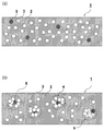
- FIG. 2 shows SEM images of cross-sections of the porous resin sheet for piezoelectric elements of the present invention actually obtained and (A) and (B) are charge-induced hollow particles 5 and hollow particles 3 respectively. And the manner of dispersion is different.
- 3A shows a uniform dispersion model diagram
- FIG. 3B shows a sea-island structure model diagram. The dotted box (a, b, etc.) in (B) of FIG.
- FIG. 3 shows an island structure having a high content of charge-induced hollow particles 5 and / or hollow particles 3 and a high hollow ratio.
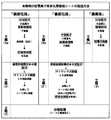
- FIG. 4 shows a flowchart of the method for producing a porous resin sheet for piezoelectric elements of the present invention in a tabular form.
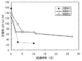
- FIG. 5 shows a graph in which the piezoelectric constant d 33 (pC / N) of the porous resin sheet for piezoelectric elements obtained in Comparative Example 1 and Examples 1 and 2 is plotted over time.
- FIG. 6 shows a graph in which the piezoelectric constant d 33 (pC / N) of the porous resin sheets for piezoelectric elements obtained in Comparative Example 2 and Example 3 is plotted over time.
- the “porous resin sheet for piezoelectric elements (hereinafter also simply referred to as“ resin sheet ”)” 1 of the present invention has “hollow particles” 3 to which “conductive substance” 4 is not attached. , And “charge-inducing hollow particles” 5 are dispersed in “matrix resin” 2.
- the “hollow particles” 3 to which the conductive substance 4 is not attached may not be present in the resin sheet 1 (not shown).
- the charge-induced hollow particles 5 are formed on the surface of the hollow particles 3 to which the conductive material 4 is not attached (the entire surface or only a part of the surface). It is attached.
- the electric charges of the “charge-inducing hollow particles” 5 and the conductive substance 4 are characterized by being higher than those of the matrix resin 2 and the hollow particles 3.
- the charge-inducing hollow particles 5 arranged along the thickness direction are close to and in contact with each other, so that a “conductive path” is easily formed. This is because it is considered that the charge easily escapes from the resin sheet surface.
- the present invention can also be said to be able to block a conductive path composed of charge-inducing hollow particles by using non-charge-inducing hollow particles 3 together and mixed with charge-inducing hollow particles 5.
- the charge retention rate of the porous resin sheet for piezoelectric elements is improved, and it is considered that high piezoelectric characteristics can be maintained over a long period of time.
- the porous resin sheet for piezoelectric elements of the present invention was actually produced, and the cross section was imaged with a scanning electron microscope [SEM].
- the scanning electron microscope used for imaging is “S-3400” manufactured by Hitachi High-Technologies Corporation, and the magnification is 100 times.
- SEM images are shown in FIGS.
- the charge-inducing hollow particles 5 and the hollow particles 3 are contained in a specific ratio, but the two particles cannot be distinguished on the image. From the SEM image in FIG. 2 (A), the particles appear to be uniformly dispersed in the resin sheet (sea structure). From the SEM image in FIG. 2 (B), the particles are clumps (islands). The islands appear to be evenly distributed.
- FIGS. 3A and 3B a uniform dispersion model and a sea-island structure model are shown in FIGS. 3A and 3B, respectively, based on the SEM image of FIG.
- FIG. 3 (A) as in FIG. 1, each particle is uniformly dispersed, whereas in FIG. 3 (B), the content of hollow particles 3 and / or charge-induced hollow particles 5 is increased.
- the island structures a and b which are high and have a high hollow ratio are contained, and the island structures a and b are uniformly dispersed.
- the island structure typically, there is a mode shown by a dotted box surrounded by a and b in FIG. 3 (B).
- the island a is a mode in which the hollow particles 3 surround the charge-induced hollow particles 5 present in the center of the island
- the island b is a mode in which the charge-induced hollow particles 5 are not in the center but are present in the outermost layer of the island. is there. It is considered that the island (particularly preferably the island a) shown in FIG. 3 (B) can behave as a pseudo large hollow particle.
- FIG. 3B The details of FIG. 3B are as follows.
- sea-island structure examples include a sea structure having a small hollow ratio (that is, a structure portion having a low content of the hollow particles 3 and / or charge-induced hollow particles 5), and an island structure having a large hollow ratio (that is, the hollow particles 3 and / or a structure part having a high content of the charge-inducing hollow particles 5).
- a high piezoelectricity is expressed in an island structure with a large hollow ratio, and the sea structure is prevented from physically approaching the polarized charges, thereby suppressing a decrease in piezoelectricity.
- a resin having a modulus of elasticity and / or conductivity different from that of the matrix resin can be used as the aggregate resin (island structure-forming resin).
- a resin sheet manufactured using a resin having a modulus of elasticity different from that of the matrix resin as an agglomerate resin undergoes non-linear deformation with respect to compressive strain during charge extraction. Deformation can be induced and thus a high piezoelectricity can be exhibited.
- the conductive material 4 is attached to the surface of the hollow particles 3 to which the conductive material 4 is not attached (not charge-induced), or at least partially or entirely. .
- the hollow particles 3 (also simply referred to as hollow particles) used in the present invention for surface coating with a conductive substance are sealed inside, that is, have a space independent from the outside.
- examples of such hollow particles include those made of glass, those made of ceramics, those made of organic polymers, and the like.
- the hollow particles made of the material having the property are preferable.
- the inside of the hollow particles 3 may be either vacuum or normal pressure depending on the use of the obtained sheet, and in the case of normal pressure, it is often filled with air or the like.
- hollow particles 3 made of glass examples include hollow particles made of soda lime glass, borosilicate glass, soda lime borosilicate glass, borosilicate soda glass, sodium silicate glass, aluminosilicate glass, and the like.
- the glass content of the hollow particles made of glass is preferably 10 to 30% by volume. If the glass content is 10% by volume or more, the hollow particles have sufficient mechanical strength, so that the hollow structure can be maintained without being broken in the processing step. The porosity can be ensured.
- the hollow particle which consists of alumina etc. is mentioned, for example.
- organic polymer either an already-expanded type or a thermally-expandable type can be applied.
- the already-expanded organic polymer include crosslinked styrene-acrylic and acrylonitrile-based polymers. Examples thereof include acrylonitrile.
- the size of the hollow particles is not particularly limited, but those having a 50% particle diameter (or cumulative median diameter) of 1 to 100 ⁇ m have high piezoelectric characteristics, high retention, and mechanical strength of the sheet itself. It is preferable in terms of securing
- the particle diameter of the hollow particles is measured based on a dynamic light scattering method.
- the porous resin sheet for piezoelectric elements can maintain a certain elasticity over a long period of time even when continuous external stress is applied to the porous resin sheet for piezoelectric elements.
- the piezoelectric characteristics of the film hardly deteriorate.
- the conductive substance 4 used in the present invention is attached to a part or all of the surface of the hollow particle 3 and has a function of holding electric charge in the porous resin sheet for piezoelectric elements.
- the conductivity of the conductive material is a material having a higher conductivity than the hollow particles 3 and the matrix resin, and more preferably the conductivity is 1.0 ⁇ 10 ⁇ 10 S / cm or more.
- the conductivity of the conductive material is measured using a double ring electrode method based on the conductivity of the single conductive material.
- the initial value of the piezoelectric constant d 33 is 110 pC / N or higher, preferably about 115 to 160 pC / N, and the piezoelectric constant d 33 after 5 days is 60 pC / N or higher, preferably 70 pC. / N or more, and the piezoelectricity d 33 after 25 days is 50 pC / N or more.
- Such a conductive substance 4 is presumed that the substance adhering to the surface of the hollow particle 3 is heat-treated in a matrix resin in an oxygen-blocking atmosphere (as a result, the substance is probably carbonized. )
- What is necessary is just to be obtained, for example, by heat-treating a surface treatment agent containing a hydrocarbon group (at a temperature equal to or higher than its thermal decomposition temperature, usually higher than the melting point of the matrix resin and lower than its decomposition temperature)
- a surface treatment agent containing the hydrocarbon group obtained by carbonization and thus subjected to heat treatment include, for example, a surfactant, a silane coupling agent, an aluminate coupling agent, and a titanate coupling agent. And may be used alone or in combination of two or more.
- the surfactant will be described in detail.
- examples of the surfactant include nonionic, zwitterionic, and cationic surfactants having a hydrocarbon group.
- the matrix resin under oxygen supply interruption conditions
- It is heated to a temperature above the decomposition temperature of the surfactant and thermally decomposed to become a conductive substance (probably decomposed into carbon, water, amorphous surfactant thermal decomposition products, etc.), and there is no environmental load.
- Inexpensive ones are desirable, and examples include those described on the Internet homepage “http://www.ecosci.jp/sa/sa.html”.
- Nonionic surfactants include fatty acid diethanolamide ⁇ R—CON (CH 2 CH 2 OH) 2 , R: an alkyl group of C1 to C20, preferably an alkyl group of about C5 to C15. ⁇ , Specifically, for example, C 11 H 23 —CON (CH 2 CH 2 OH) 2 , polyoxyethylene alkyl ether (AE) [higher alcohol type, RO (CH 2 CH 2 O) n H, R : An alkyl group of about C1-20, n: an integer of about 1-30, preferably about 5-15], specifically, for example, C 12 H 25 —O (CH 2 CH 2 O) 8 H Oxyethylene alkyl phenyl ether ⁇ (APE) (R- (C 6 H 4 ) O (CH 2 CH 2 O) n H, R: C 1-20 alkyl group, preferably about C 5-15 alkyl group, n: 1 to 30, preferably an integer of about 5 to 15) ⁇ , specifically, for example, C 9 H 19-
- Zwitterionic surfactants include alkylcarboxybetaines [betaines] ⁇ RN + (CH 3 ) 2 ⁇ CH 2 COO ⁇ , R: C1-20, preferably an alkyl group of about C5-15 ⁇ , specifically For example, C 12 H 25 —N + (CH 3 ) 2 .CH 2 COO — and the like can be mentioned.
- R an alkyl group of about C1 to C20, preferably about C5 to C15.
- ⁇ Specifically, for example, C 12 H 25 -N + ( CH 3) 3 ⁇ Cl - , etc., dialkyl dimethylammonium chloride ⁇ R 2 -N + (CH 3 ) 2 ⁇ Cl -
- R: C1 ⁇ 20 preferably an alkyl group having about C5 ⁇ 15) ⁇ , specifically, for example, C 12 H 25 -N + ( C 8 H 17) (CH 3) 2 ⁇ Cl - , etc., alkyl pyridinium chloride ⁇ R- (N + C 5 H 5 ) ⁇ Cl ⁇
- R: C1-20 preferably an alkyl group of about C5-15) ⁇ , specifically, for example, C 12 H 25- (N + C 5 H 5 ) ⁇
- nonionic surfactants are preferable in terms of suppressing charge decay after heat treatment, and polyoxyethylene alkyl ether is particularly preferable.
- a fluorosurfactant having a perfluoroalkyl group and having excellent wettability, permeability and the like can be mentioned.
- fluorine telomer alcohol F (CF 2 ) n CH 2 CH 2 OH, n: repeating unit
- nonionic surfactant for example, a nonionic surfactant of “Nonion ID-206” manufactured by Nippon Oil & Fats Co., Ltd. (thermal decomposition starting temperature under normal pressure: 150 ° C.) can be preferably used.
- fluorine-based surfactant fluorine-containing surfactant (Surflon) “S-241” (thermal decomposition start temperature under normal pressure: 220 ° C., nonionic system) manufactured by AGC Seimi Chemical Co., Ltd.
- Nonionic fluorinated surfactants or anionic fluorinated surfactants such as “Factent 251” manufactured by Neos Co., Ltd. (thermal decomposition start temperature under normal pressure: 220 ° C.) (for example, commercial products of Neos Co., Ltd., etc.) ) Can be preferably used.
- the blending amount of the surfactant is usually about 0.1 to 5% by weight with respect to 100% by weight of the hollow particles.
- the conductive substance 4 may be one or more selected from the group consisting of carbon, graphite, and platinum.
- the charge-inducing hollow particles 5 such a conductive substance 4 may be the insulating hollow particles 3 described above. It may be deposited on the surface.
- the matrix resin 2 used in the present invention is not particularly limited, and examples thereof include resins having a thermal decomposition start temperature of 150 to 450 ° C., for example, a copolymer of tetrafluoroethylene and perfluoroalkyl vinyl ether [PFA] (for example, apparent Density: 1.0 to 1.2 g / ml (according to ASTM D2116)), tetrafluoroethylene and hexafluoropropylene copolymer [FEP] (for example, apparent density: 1.0 to 1.2 g / ml), poly Chlorotrifluoroethylene [PCTFE] (eg apparent density: 0.9 to 1.2 g / ml), copolymer of tetrafluoroethylene and ethylene [ETFE] (eg apparent density: 1.0 to 1.2 g / ml) ml), polyvinylidene fluoride [PVdF], polyvinyl fluoride
- thermoplastic resin from the viewpoint of easy work of uniformly dispersing the hollow particles 3 and the charge-inducing hollow particles 5.
- the matrix resin is preferably a material that is more separated from the hollow particles that are easily charged positively and in a charge train, for example, a fluorine-containing resin or an imide resin, from the viewpoint of charging characteristics.
- the “material separated by the charged column” means the Textile Society edition, “Fiber Handbook (raw material edition)”, Maruzen (1968), Hidetoshi Tsuchida, Taku Shinohara, polymer, 16,347. (1967) means a material such as a fluorine-containing resin in which the charged column is positioned on the minus side of the glass hollow particles based on the charged column table disclosed in (1967).
- the matrix resin is preferably a resin having a high melting temperature and a high thermal decomposition starting temperature from the viewpoint of heat resistance, for example, a fluorine-containing resin or an imide resin.
- the surface treatment agent containing a hydrocarbon group is heat-treated to have a desired conductivity (perhaps carbonized).
- Such a matrix resin 2 preferably has a thermal decomposition start temperature in the range of 150 ° C. to 450 ° C., more preferably a thermal decomposition start temperature in the range of 300 ° C.
- thermo decomposition Fluorine-containing resins such as FEP (pyrolysis start temperature: about 400 ° C), ETFE (pyrolysis start temperature: about 360 ° C), PCTFE (pyrolysis start temperature: about 340 ° C)
- an imide resin such as polyimide (thermal decomposition start temperature: about 400 ° C.), bismaleimide (thermal decomposition start temperature: about 400 ° C.), or the like.
- the thermal decomposition start temperature (carbonization temperature) at which the surface treatment agent containing a hydrocarbon group is heat-treated and exhibits conductivity more specifically, a temperature that is usually 50 ° C. lower than the thermal decomposition temperature of the matrix resin 2, Preferably, the temperature is lower by 100 ° C. or more from the viewpoint of ease of heat treatment temperature control.
- the porous resin sheet 1 for piezoelectric elements is excellent in heat resistance and weather resistance, and particularly excellent in temporal stability of piezoelectric characteristics at a high temperature of 80 ° C. or higher. preferable.
- any of the “pre-carbonization method”, “post-carbonization method” and “evaporation method” can be adopted as the method for producing the porous resin sheet 1 for piezoelectric elements of the present invention.
- the sea-island structure in the porous resin sheet for piezoelectric elements of the present invention it can be produced by further applying a “two-stage dispersion method” to the above production method.
- Step (3) A step of injecting electric charge into the sheet by subjecting the sheet obtained in the step (2) to polarization treatment.
- This pre-carbonization method can form the charge-induced hollow particles 5 in the step (1a).
- a surfactant containing a hydrocarbon group is treated with an appropriate solvent (for example, a method of diluting with a surfactant and immersing hollow particles in the surfactant solution can be used.
- the amount of the surfactant necessary for coating the hollow particles in the solvent depends on the type of the surfactant, but is preferably less than 5%, more preferably based on the weight of the hollow particles. Is about 0.1 to 1.0%.
- the amount of the surfactant exceeds 5% with respect to the weight of the hollow particles, there is a possibility that electric charges can easily escape from the porous resin sheet for piezoelectric elements. On the other hand, if it is less than 0.1%, it may be difficult to form a conductive material on the hollow particles. Thus, when the surface treating agent containing a hydrocarbon group is used, a conductive material can be efficiently formed in a small amount.
- the amount of the surfactant to be added to the solvent is not particularly limited as long as the surface treatment agent-containing liquid can be satisfactorily adhered to the surface of the hollow particle 3.
- the heat treatment of the hollow particles includes, for example, treatment at 250 to 400 ° C. for 10 to 120 minutes while blocking oxygen.
- the hollow particles 3 are imparted with electrical conductivity to the surface because at least part (preferably all) of the hydrocarbon group part of the surface treatment agent containing hydrocarbon groups is probably It is considered that the conductive material is formed on at least a part (preferably all) of the surface of the hollow particles.
- the charge-inducing hollow particles obtained in the step (1a) are kneaded with the matrix resin and then molded to obtain a resin sheet.
- This resin sheet can be produced by a conventionally known method.
- the matrix resin is a thermoplastic resin
- the charge-inducing hollow particles and the matrix resin are formed by a molding machine such as a single-screw or twin-screw extruder. After being melt-kneaded, it is molded into a sheet by using, for example, a pressure molding machine or a T die.
- the molding temperature is usually about the same as the melting temperature of the matrix resin.
- an elastic control auxiliary agent eg, silicon resin fine particles, styrene resin fine particles, acrylic resin fine particles, etc.
- an elastic control auxiliary agent eg, silicon resin fine particles, styrene resin fine particles, acrylic resin fine particles, etc.
- step (3) by applying a polarization treatment to the sheet obtained in the step (2), charges can be injected into the sheet. More specifically, charges are injected from the surface of the sheet molded in step (2) by a polarization process such as corona discharge.
- the injected charge is concentrated on the shell part of the charge-inducing hollow particles, and induces polarization in the hollow structure.
- a part of the induced charge is considered to hold the charge at the interface between the charge-induced hollow particles and the matrix resin.
- the internally polarized sheet can take out electric charges through the front and back surfaces of the sheet by applying a compressive load in the sheet thickness direction. That is, charge transfer occurs with respect to the external load (electric circuit), and an electromotive force is obtained.
- the surface treatment agent containing the hydrocarbon group attached to at least a part of the particle is made conductive (possibly carbonized), and the conductive substance is attached to at least a part of the surface of the hollow particle.
- step (1b) at least a part (preferably all) of the surface of the hollow particles was coated with a surface treatment agent containing a hydrocarbon group, and then obtained as step (2 ′) in step (1b).
- the hollow particles having a surface treatment agent containing a hydrocarbon group attached to at least a part (preferably all) of the surface are kneaded with a matrix resin, and then molded into a sheet, and at least a part of the surface of the hollow particles (preferably The surface treatment agent adhering to (all) is subjected to thermal decomposition by being kneaded in an oxygen non-supplying atmosphere and possibly carbonized to form a conductive substance on the surface of the hollow particles.
- Step (1b) is the same as the case of the coating in the step (1a) described above.
- melt-kneading conditions and molding conditions in the step (2 ′) are as follows.
- the melting temperature is preferably 10 to 50 ° C. higher than the melting point of the matrix resin.
- the melting time is preferably 1 to 30 minutes.
- the heating temperature at the time of molding is preferably a temperature that is 10 to 50 ° C. higher than the melt kneading temperature and is lower than the thermal decomposition start temperature of the matrix resin.
- the heating time is preferably 10 to 120 minutes.
- the case where FEP (melting point: 260 ° C., thermal decomposition start temperature: 400 ° C.), for example, is used as the matrix resin will be described as an example as follows.
- a hollow particle having a surface attached with a surface treatment agent containing a hydrocarbon group and FEP are melt-kneaded with a molding machine such as a single-screw or twin-screw extruder (usually at 300 to 310 ° C. for about 30 minutes).
- the matrix resin is thermally decomposed at a temperature higher than the melt kneading temperature (eg, about 10 to 50 ° C.). After heating at 350 ° C. below the starting temperature for 10 to 120 minutes, pressurize to a desired shape under air cooling conditions (eg, normal temperature) at 40 to 150 kgf / cm 2 or under heating.
- a temperature higher than the melt kneading temperature eg, about 10 to 50 ° C.
- the hydrocarbon group portion of the surface treatment agent containing the hydrocarbon group covering the surface of the hollow particles is at least a part thereof It is considered that (preferably all) is carbonized due to thermal decomposition when heated at the above high temperature in an oxygen non-supplying atmosphere. It seems that hollow particles will be obtained.
- Process (3) is as described above.
- the charge-induced hollow particles can be formed by evaporating a conductive material on at least a part (preferably all) of the surface of the hollow particles.
- a conductive material preferably all of the surface of the hollow particles.
- Graphite, platinum and the like and may be used alone or in combination of two or more.
- a conventionally known vapor deposition method can be used.
- a conductive material may be attached to the surface of the hollow particles by plating.
- an island structure portion (agglomerates having a high content of hollow particles 3 and / or charge-induced hollow particles 5, preferably hollow particles 3 and charge-induced hollows, as indicated by symbols a and b)
- the porous resin sheet for piezoelectric elements of the present invention in which the aggregates having a high content of particles 5 are uniformly dispersed can be produced as follows.
- a porous resin sheet for a piezoelectric element of the present invention having a sea-island structure can be produced in the same manner as any of the pre-carbonization method, post-carbonization method, and vapor deposition method except that is used.
- an aggregate is prepared by melting and kneading a resin (aggregate resin, that is, an island structure forming resin) having a higher viscosity than the matrix resin, and charge-induced hollow particles and / or hollow particles.
- the porous resin sheet for piezoelectric elements of the present invention having a sea-island structure can be produced.
- the agglomerated structure is difficult to dissolve even if the agglomerates are diluted with a molten matrix resin, and a resin sheet having the desired island structure remains. Obtainable.
- the hollowness of the island structure contained in the resin sheet (that is, the aggregate in which the content of the hollow particles 3 and / or the charge-induced hollow particles 5 is higher than that of the sea structure portion) is 30 to 80 volumes. % Is preferable in that sufficient electric charge is stored in the sheet and the piezoelectricity is increased, and the sea structure (that is, a structure in which the content of the hollow particles 3 and / or the charge-induced hollow particles 5 is lower than that of the island structure portion)
- the porosity of the part is preferably from 0 to 10% by volume because the distance between the holes is maintained, and the charges polarized in the island structure can be maintained over a long period of time.
- the overall sea-island structure is preferably 10 to 70% by volume, and preferably 15 to 60% by volume, in terms of the initial value of piezoelectricity, its retainability, and long-term mechanical strength.
- the sea structure, the island structure, and the overall hollow ratio of the sea-island structure are calculated by the following formula based on the amount of material used for creating the sheet.
- Hollow ratio (%) ((volume A ⁇ volume B) / volume A) ⁇ 100, Volume A: Volume calculated from material weight and material specific gravity (true specific gravity).
- Volume B Volume calculated from material weight and specific gravity excluding the hollow structure.
- the hollow ratio of the entire sea-island structure is less than 15% by volume, sufficient electric charge cannot be stored, and there may be a case where a sufficient piezoelectric ratio as a piezoelectric material cannot be secured.
- the hollowness exceeds 60% by volume, the distance between the island structures is substantially close, so the effect of forming the sea-island structure is reduced, that is, the purpose of enhancing the retention of piezoelectric characteristics cannot be achieved. There is a case.
- the size of the island structure is preferably about 0.1 to 1.0 times the thickness of the sheet molding.
- the resin used for the preparation of the aggregate is not particularly limited as long as it has a higher viscosity than the matrix resin during kneading and molding, and examples thereof include the resins exemplified above as the matrix resin. It is done. Among these, it is preferable to use a resin having an elastic modulus different from that of the matrix resin as the resin for aggregates (resin for island structure creation).
- the difference in elastic modulus between the resin for aggregates and the matrix resin is preferably 10 MPa or more from the viewpoint that the initial value of piezoelectricity is high and the retention rate can be increased.
- the viscosity of the resin for aggregates is preferably 10 times or more the viscosity of the matrix resin at the kneading temperature.
- the elastic modulus of these resins can be measured based on the following method according to JIS K7210.
- the resin as a raw material is formed into a 3 cm ⁇ 3 cm ⁇ 2 mm sheet by a known method, and the obtained sheet is tested with a universal compression tester (manufactured by Minebea Co., Ltd .; “Technograph TG-50kN”) at a test speed of 5 mm / min. Then, a compressive stress-strain curve is created from the measured value and calculated based on this.
- a universal compression tester manufactured by Minebea Co., Ltd .; “Technograph TG-50kN”
- a resin sheet manufactured using a resin having a modulus of elasticity different from that of a matrix resin as an agglomerate resin causes non-linear deformation with respect to compressive strain. Therefore, deformation of the entire resin sheet can be induced by minute stress. Therefore, a high piezoelectricity can be exhibited when external stress is applied.
- a fluorine-containing resin or an imide resin as the aggregate resin and the matrix resin from the viewpoints of heat resistance and weather resistance of the porous resin sheet for piezoelectric elements.
- a layer composed of the aggregate can be further formed on the surface of the aggregate prepared as described above, and this method is referred to as “three-stage dispersion method” in the present invention.
- the three-stage dispersion method is preferable because it is easy to form the island structure a in FIG.
- Example 1 Manufacture of porous resin sheet for piezoelectric elements
- composition is soda-lime borosilicate glass, 50% particle size is 16 ⁇ m, and glass amount (calculated value) is 24 (volume) 1% by weight of nonionic surfactant based on the weight of the hollow particles (NON-ID-ID manufactured by NOF Corporation), with a conductivity of 1.0 ⁇ 10 ⁇ 13 S / cm. 206; polyoxyethylene isodecyl ether: thermal decomposition onset temperature: 150 ° C.), the surfaces of the hollow particles were coated.
- the hollow particles were immersed and coated in a solution obtained by diluting a predetermined amount of a surfactant 50 times with methyl alcohol.
- the coating with the nonionic surfactant on the surface of the hollow particles was confirmed using SEM.
- This nonionic surfactant (Nonion ID-206) does not contain a solvent.
- FEP copolymer of tetrafluoroethylene and hexafluoropropylene; NEOFLON TM FEP “NP-101” manufactured by Daikin Industries, Ltd .; Conductivity: 1.0 ⁇ 10 ⁇ 16 S / cm; MFR: 24 g / 10 min (ASTMD2116); Melting point: 255 ° C. (ASTMD2116); Apparent density 1.21 g / ml (JISK6891)) 100 g and 300-310 ° C. After being melt-kneaded for 30 minutes, the sample was compressed into a sheet (heated at 350 ° C. for 40 minutes and then pressurized at 60 kgf / cm 2 under air cooling conditions) to prepare a sample sheet having a thickness of 0.5 mm.
- the hollowness of the sample sheet was 30% by volume.
- the hollow ratio was calculated by the following method.
- Volume B Volume calculated from material weight and specific gravity excluding the hollow structure.
- the true specific gravity of the hollow particles is 0.6 g / cm 3 (see Sumitomo 3M Co., Ltd., product catalog “Glass Bubbles-High Functional Additives”), and the specific gravity of the hollow particles excluding the hollow structure is 2.5 g / cm 3. 3
- the specific gravity of FEP was calculated as 2.1 g / cm 3 .
- the surfactant adhering to the surface of the hollow particles by the sheet preparation process is heated at a melting temperature such as FEP, which is a temperature exceeding the decomposition temperature, so that the conductivity is 1.0 ⁇ 10 ⁇ 10 S / cm. It was a conductive substance. From this, it is considered that a part or all of the surfactant adhering to the surface of the hollow particles by the sheet preparation process is carbonized (hereinafter, abbreviated as “carbonized layer” in some cases). ).
- the conductivity of the carbonized layer was measured using a resistivity meter (digital) on a carbonized layer prepared by heating a surfactant coating layer on a glass substrate at 300 ° C. under reduced pressure (oxygen-blocking environment) for a predetermined time.
- a super insulation / micro ammeter DSM-8104 manufactured by Hioki Electric Co., Ltd. was used, and the measurement was performed based on the double ring electrode method.
- This sample sheet was subjected to a polarization treatment by corona discharge for 3 minutes at room temperature with a distance of 12.5 mm between electrodes, a voltage between electrodes of 3 kV using a corona discharge device manufactured by Kasuga Electric Co., Ltd., and a porous resin sheet for piezoelectric elements Manufactured.
- a constant AC acceleration ⁇ (frequency: 90 to 300 Hz, size: 2 to 10 m / s 2 ) is given in the thickness direction of the sample for evaluation under the condition of room temperature (20 ° C) and humidity of 20%.
- the response charge at that time was measured, and the initial piezoelectric constant d 33 (pC / N) was determined (this time is 0 day).
- Example 2 In Example 1, a porous resin sheet for a piezoelectric element was produced in the same manner as in Example 1 except that the nonionic surfactant used was changed to 0.5% by weight based on the weight of the hollow particles. Then, the piezoelectric performance was evaluated in the same manner as in Example 1, and the results are shown in Table 1 and FIG.
- Example 1 In Example 1, the nonionic surfactant used with respect to the weight of the hollow particles was changed to 0% (that is, the hollow particles were not coated with the surfactant). A porous resin sheet was produced. Then, the piezoelectric performance was evaluated in the same manner as in Example 1, and the results are shown in Table 1 and FIG.
- d 33 of the porous resin sheet for piezoelectric elements produced in the examples is maintained at 60 pC / N or more even after 5 days, and the conductive material is on the surface. It can be seen that the retention of the piezoelectric characteristics is high as compared with Comparative Example 1 using hollow particles that are not attached.
- Example 3 Evaluation of heat resistance of porous resin sheet for piezoelectric elements
- the porous resin sheet for piezoelectric elements produced in Example 2 was subjected to heat treatment by being allowed to stand for 100 hours in an electric furnace maintained at 80 ° C. after evaluation in Example 2 after 5 days. Thereafter, the sheet was taken out from the electric furnace, cooled to room temperature, and then evaluated for piezoelectric characteristics in the same manner as in Example 1 (corresponding to measurement after 9 days from the date of manufacture).
- d 33 of the porous resin sheet for piezoelectric elements after the heat treatment was 61 pC / N, and the same characteristics as the sheet before the heat treatment were maintained.
- the porous resin sheet for piezoelectric elements of the present invention has heat resistance that does not deactivate the piezoelectric characteristics even in a high temperature environment such as 80 ° C.
- Example 4 ⁇ Manufacture of island structure pellets> As hollow particles, hollow glass beads (Potters Barotini, 60P18, conductivity: 1.0 ⁇ 10 ⁇ 14 S / cm) (composition is borosilicate glass, particle diameter is 16 ⁇ m, true specific gravity is 0.6) g / cm 3 , specific gravity assuming hollow particles as solid is 2.5 g / cm 3 , glass amount (calculated value) is 24 (volume ratio%)), and weight of hollow particles (100 wt%) On the other hand, the surface of the hollow particles was coated with 1% by weight of a nonionic surfactant (Nonchi ID-206 manufactured by NOF Corporation; thermal decomposition start temperature: 150 ° C.).
- a nonionic surfactant Nonchi ID-206 manufactured by NOF Corporation; thermal decomposition start temperature: 150 ° C.
- the hollow particles were immersed and coated in a solution obtained by diluting a predetermined amount of surfactant with methyl alcohol 50 times by weight at normal temperature and normal pressure.
- This nonionic surfactant (Nonion ID-206) does not contain a solvent.
- NEOFLON FEP manufactured by Daikin Industries, model number: NP101, MFR: 24 g / 10 min (according to ASTM D2116), viscosity at 300 ° C: 1.0 ⁇ 10 6 poise, melting point 255 ° C (according to ASTM D2116), apparent 29.0 g of density 1.21 g / ml (JIS K 6891 compliant), specific gravity: 2.1 g / cm 3 , conductivity: 1.0 ⁇ 10 ⁇ 16 S / cm 2) is kneaded at 300 ° C. for 5 minutes using a lab plast mill, Further, 23.0 g of the island structure pellets were added as an island structure, and then kneaded at 300 ° C. for 10 minutes to prepare sea island structure pellets.
- the material ratio was calculated from the weight and density of each material and the amount of hollow particle glass.
- sea-island structure pellets were placed in a mold, heated at 350 ° C./1 h, and then compressed at 3 mm MPa under air cooling to form a sample sheet.
- the surfactant adhering to the surface of the hollow particles was a conductive substance having a conductivity of 1.0 ⁇ 10 ⁇ 10 S / cm.
- the conductivity is measured with a resistivity meter (digital super-insulation / digital super-insulation) on a carbonized layer prepared by heating a surfactant coating layer on a glass substrate at 300 ° C. under reduced pressure (oxygen-blocking environment) for a predetermined time.
- the measurement was performed based on the double ring electrode method using a microammeter DSM-8104 (manufactured by Hioki Electric Co., Ltd.).
- Porous resin sheet for piezoelectric elements the structure is the same before and after the polarization treatment in step (3)
- 2 Matrix resin
- 3 hollow particles
- 4 conductive material
- 5 charge-induced hollow particles
- a, b ... island structure (agglomerates having a high content of hollow particles 3 and / or charge-induced hollow particles 5
Landscapes
- Chemical & Material Sciences (AREA)
- Engineering & Computer Science (AREA)
- Materials Engineering (AREA)
- Health & Medical Sciences (AREA)
- Chemical Kinetics & Catalysis (AREA)
- Medicinal Chemistry (AREA)
- Polymers & Plastics (AREA)
- Organic Chemistry (AREA)
- Power Engineering (AREA)
- Microelectronics & Electronic Packaging (AREA)
- Manufacture Of Porous Articles, And Recovery And Treatment Of Waste Products (AREA)
- Compositions Of Macromolecular Compounds (AREA)
Abstract
Le problème à résoudre dans le cadre de cette invention consiste à proposer une feuille de résine cellulaire pour des éléments piézoélectriques, qui soit capable de conserver des propriétés piézoélectriques élevées dans une large plage de températures d'utilisation sur une longue durée, et qui soit excellente en termes de résistance à l'environnement et de résistance thermique. Il consiste également à proposer un procédé de fabrication de la feuille de résine cellulaire.
La solution consiste en une feuille de résine cellulaire pour des éléments piézoélectriques qui est caractérisée en ce qu'elle comprend une résine matricielle dans laquelle sont dispersées au moins des particules creuses d'induction de charge, les particules creuses à induction de charge comprenant des particules creuses et une substance conductrice adhérant à au moins une partie des surfaces des particules creuses, et la substance conductrice présentant une conductivité supérieure à celle des particules creuses et de la résine matricielle.
Applications Claiming Priority (6)
| Application Number | Priority Date | Filing Date | Title |
|---|---|---|---|
| JP2012044541 | 2012-02-29 | ||
| JP2012-044541 | 2012-02-29 | ||
| JP2012120669 | 2012-05-28 | ||
| JP2012-120669 | 2012-05-28 | ||
| JP2012240412 | 2012-10-31 | ||
| JP2012-240412 | 2012-10-31 |
Publications (1)
| Publication Number | Publication Date |
|---|---|
| WO2013129142A1 true WO2013129142A1 (fr) | 2013-09-06 |
Family
ID=49082343
Family Applications (1)
| Application Number | Title | Priority Date | Filing Date |
|---|---|---|---|
| PCT/JP2013/053735 WO2013129142A1 (fr) | 2012-02-29 | 2013-02-15 | Feuille de résine cellulaire pour élément piézoélectrique et son procédé de fabrication |
Country Status (2)
| Country | Link |
|---|---|
| JP (1) | JPWO2013129142A1 (fr) |
| WO (1) | WO2013129142A1 (fr) |
Cited By (2)
| Publication number | Priority date | Publication date | Assignee | Title |
|---|---|---|---|---|
| US20150015120A1 (en) * | 2012-02-07 | 2015-01-15 | Sumitomo Electric Industries, Ltd. | Piezoelectric element including fluororesin film |
| JP2019508529A (ja) * | 2016-01-13 | 2019-03-28 | ヘンケル・アクチェンゲゼルシャフト・ウント・コムパニー・コマンディットゲゼルシャフト・アウフ・アクチェンHenkel AG & Co. KGaA | 充填剤を含有する反応性ポリウレタンホットメルト接着剤 |
Citations (5)
| Publication number | Priority date | Publication date | Assignee | Title |
|---|---|---|---|---|
| JPS58171878A (ja) * | 1982-04-02 | 1983-10-08 | Mitsubishi Petrochem Co Ltd | 高分子複合圧電体 |
| JP2008266563A (ja) * | 2007-03-22 | 2008-11-06 | Univ Of Tokyo | エレクトレット及びこれを備える静電誘導型変換素子 |
| WO2009113432A1 (fr) * | 2008-03-14 | 2009-09-17 | コニカミノルタエムジー株式会社 | Matériau piézoélectrique organique, oscillateur ultrasonore utilisant le matériau, procédé de fabrication de l'oscillateur ultrasonore, sonde ultrasonore, et dispositif d'imagerie pour diagnostic médical ultrasonore |
| JP2010508416A (ja) * | 2006-11-06 | 2010-03-18 | ヘクセル コンポジット、リミテッド | 改良型複合材料 |
| JP2010080743A (ja) * | 2008-09-26 | 2010-04-08 | Kaneka Corp | エレクトレット |
-
2013
- 2013-02-15 WO PCT/JP2013/053735 patent/WO2013129142A1/fr active Application Filing
- 2013-02-15 JP JP2014502129A patent/JPWO2013129142A1/ja active Pending
Patent Citations (5)
| Publication number | Priority date | Publication date | Assignee | Title |
|---|---|---|---|---|
| JPS58171878A (ja) * | 1982-04-02 | 1983-10-08 | Mitsubishi Petrochem Co Ltd | 高分子複合圧電体 |
| JP2010508416A (ja) * | 2006-11-06 | 2010-03-18 | ヘクセル コンポジット、リミテッド | 改良型複合材料 |
| JP2008266563A (ja) * | 2007-03-22 | 2008-11-06 | Univ Of Tokyo | エレクトレット及びこれを備える静電誘導型変換素子 |
| WO2009113432A1 (fr) * | 2008-03-14 | 2009-09-17 | コニカミノルタエムジー株式会社 | Matériau piézoélectrique organique, oscillateur ultrasonore utilisant le matériau, procédé de fabrication de l'oscillateur ultrasonore, sonde ultrasonore, et dispositif d'imagerie pour diagnostic médical ultrasonore |
| JP2010080743A (ja) * | 2008-09-26 | 2010-04-08 | Kaneka Corp | エレクトレット |
Cited By (4)
| Publication number | Priority date | Publication date | Assignee | Title |
|---|---|---|---|---|
| US20150015120A1 (en) * | 2012-02-07 | 2015-01-15 | Sumitomo Electric Industries, Ltd. | Piezoelectric element including fluororesin film |
| US9343653B2 (en) * | 2012-02-07 | 2016-05-17 | Sumitomo Electric Industries, Ltd. | Piezoelectric element including fluororesin film |
| JP2019508529A (ja) * | 2016-01-13 | 2019-03-28 | ヘンケル・アクチェンゲゼルシャフト・ウント・コムパニー・コマンディットゲゼルシャフト・アウフ・アクチェンHenkel AG & Co. KGaA | 充填剤を含有する反応性ポリウレタンホットメルト接着剤 |
| US11091677B2 (en) | 2016-01-13 | 2021-08-17 | Henkel Ag & Co. Kgaa | Reactive polyurethane hot melt adhesives containing fillers |
Also Published As
| Publication number | Publication date |
|---|---|
| JPWO2013129142A1 (ja) | 2015-07-30 |
Similar Documents
| Publication | Publication Date | Title |
|---|---|---|
| WO2014069477A1 (fr) | Empilement piézoélectrique | |
| Huang et al. | High-k polymer nanocomposites with 1D filler for dielectric and energy storage applications | |
| Yang et al. | Lead magnesium niobate‐filled silicone dielectric elastomer with large actuated strain | |
| Wang et al. | Enhanced thermal conductivity of segregated poly (vinylidene fluoride) composites via forming hybrid conductive network of boron nitride and carbon nanotubes | |
| US9144926B2 (en) | Functional molded article and method for producing same | |
| US20110186437A1 (en) | Polymeric Electret Film and Method of Manufacturing the Same | |
| Yang et al. | Disclosed dielectric and electromechanical properties of hydrogenated nitrile–butadiene dielectric elastomer | |
| Yang et al. | A high-performance dielectric elastomer consisting of bio-based polyester elastomer and titanium dioxide powder | |
| Liu et al. | Tailoring dielectric properties of polymer composites by controlling alignment of carbon nanotubes | |
| WO2015147049A1 (fr) | Corps piézoélectrique composite polymère | |
| KR20080102888A (ko) | 압전 복합 소재 | |
| Kumar et al. | Enhancement of electromechanical properties of natural rubber by adding barium titanate filler: An electro‐mechanical study | |
| WO2013129142A1 (fr) | Feuille de résine cellulaire pour élément piézoélectrique et son procédé de fabrication | |
| Bian et al. | Porous conductive elastomeric composites with carbon nanotubes suspended in the narrow pores from Co-continuous polymer blend nanocomposites | |
| KR101471161B1 (ko) | 스프레이 코팅을 통해 제조된 β-상 PVDF 필름을 포함하는 압전소자 | |
| Yang et al. | The role of interfacial H-bonding on the electrical properties of UV-cured resin filled with hydroxylated Al2O3 nanoparticles | |
| JP6180148B2 (ja) | 複合制振材料 | |
| Lvye et al. | Nanonet-/fiber-structured flexible ceramic membrane enabling dielectric energy storage. | |
| JPH06342947A (ja) | 多孔質圧電体の製造方法及びポリマ−圧電性多孔膜 | |
| Huang et al. | Study on the improved electromechanical properties of composited dielectric elastomer by tailoring three-dimensional segregated multi-walled carbon nanotube (MWCNT) network | |
| KR20230112104A (ko) | 테트라플루오로에틸렌계 폴리머의 조성물, 적층체 및 필름 | |
| KR101440484B1 (ko) | 스프레이 코팅을 이용한 β-상 PVDF 필름의 제조방법 | |
| KR101484304B1 (ko) | 산화알루미늄이 코팅된 그라펜, 이의 제조방법과 이를 포함하는 나노복합재료 | |
| Wang et al. | Synergetic improvement of dielectric properties and thermal conductivity in Zn@ ZnO/carbon fiber reinforced silicone rubber dielectric elastomers | |
| Zhang et al. | Large-scale fabrication and performance improvement of polyvinylidene fluoride piezoelectric composite films |
Legal Events
| Date | Code | Title | Description |
|---|---|---|---|
| 121 | Ep: the epo has been informed by wipo that ep was designated in this application |
Ref document number: 13755389 Country of ref document: EP Kind code of ref document: A1 |
|
| ENP | Entry into the national phase |
Ref document number: 2014502129 Country of ref document: JP Kind code of ref document: A |
|
| NENP | Non-entry into the national phase |
Ref country code: DE |
|
| 122 | Ep: pct application non-entry in european phase |
Ref document number: 13755389 Country of ref document: EP Kind code of ref document: A1 |