WO2013129088A1 - 消化管用デバイス - Google Patents
消化管用デバイス Download PDFInfo
- Publication number
- WO2013129088A1 WO2013129088A1 PCT/JP2013/053152 JP2013053152W WO2013129088A1 WO 2013129088 A1 WO2013129088 A1 WO 2013129088A1 JP 2013053152 W JP2013053152 W JP 2013053152W WO 2013129088 A1 WO2013129088 A1 WO 2013129088A1
- Authority
- WO
- WIPO (PCT)
- Prior art keywords
- expansion
- fluid
- digestive
- flow path
- digestive tract
- Prior art date
- Legal status (The legal status is an assumption and is not a legal conclusion. Google has not performed a legal analysis and makes no representation as to the accuracy of the status listed.)
- Ceased
Links
Images
















Classifications
-
- A—HUMAN NECESSITIES
- A61—MEDICAL OR VETERINARY SCIENCE; HYGIENE
- A61F—FILTERS IMPLANTABLE INTO BLOOD VESSELS; PROSTHESES; DEVICES PROVIDING PATENCY TO, OR PREVENTING COLLAPSING OF, TUBULAR STRUCTURES OF THE BODY, e.g. STENTS; ORTHOPAEDIC, NURSING OR CONTRACEPTIVE DEVICES; FOMENTATION; TREATMENT OR PROTECTION OF EYES OR EARS; BANDAGES, DRESSINGS OR ABSORBENT PADS; FIRST-AID KITS
- A61F5/00—Orthopaedic methods or devices for non-surgical treatment of bones or joints; Nursing devices ; Anti-rape devices
- A61F5/0003—Apparatus for the treatment of obesity; Anti-eating devices
- A61F5/0013—Implantable devices or invasive measures
- A61F5/0076—Implantable devices or invasive measures preventing normal digestion, e.g. Bariatric or gastric sleeves
-
- A—HUMAN NECESSITIES
- A61—MEDICAL OR VETERINARY SCIENCE; HYGIENE
- A61B—DIAGNOSIS; SURGERY; IDENTIFICATION
- A61B17/00—Surgical instruments, devices or methods
- A61B2017/00743—Type of operation; Specification of treatment sites
- A61B2017/00818—Treatment of the gastro-intestinal system
Definitions
- the present invention relates to a digestive tract device installed in the digestive tract.
- GIP glucose-dependent insulin secretion stimulating polypeptide
- glucagon which is a gastrointestinal hormone
- GIP and glucagon are considered to be factors that decrease insulin secretion.
- insulin secretion becomes difficult to be inhibited.
- GLP-1 is considered to be a factor that promotes insulin secretion. In this way, bypass surgery not only limits the absorption of ingested nutrients, but also promotes the secretion of insulin by the action of gastrointestinal hormones, thereby reducing blood glucose levels and is considered effective in the treatment of diabetes and obesity. ing.
- Patent Document 1 describes a device including two balloons arranged so as to sandwich a pyloric ring of the stomach and a cylindrical sleeve extending from the balloons toward the small intestine. This device is minimally invasive because it can be installed orally, allowing nutrients that reach the pyloric ring to reach the lower part of the small intestine without passing through the sleeve and touching the upper part of the small intestine it can.
- Patent Document 1 when a device such as that described in Patent Document 1 is installed in the digestive tract, it is usually necessary to install the device while observing with X-rays, and the operation is complicated and the burden on the living body is large.
- the present invention has been made to solve the above-described problems, and an object of the present invention is to provide a gastrointestinal device capable of improving the operability and reducing the burden on the living body.
- a device for a digestive tract for achieving the above object is a first part that can be expanded so that an outer diameter is widened by inflow of a cylindrical part having a through-hole and a fluid that is provided in the cylindrical part and is supplied from the outside.
- an adjusting unit for adjusting the flow of the fluid from the outside is a first part that can be expanded so that an outer diameter is widened by inflow of a cylindrical part having a through-hole and a fluid that is provided in the cylindrical part and is supplied from the outside.
- An extension part, a second extension part that is provided on the distal end side of the first extension part and can be extended so that the outer diameter is widened, and the second extension part is extended before the first extension part.
- an adjusting unit for adjusting the flow of the fluid from the outside is a first
- the gastrointestinal tract device configured as described above has an adjustment unit that adjusts the flow of the fluid from the outside so as to expand the second expansion portion before the first expansion portion. Moreover, the 2nd expansion part located in the distal side (anus side) rather than the 1st expansion part can be expanded previously. Therefore, after expanding the second expansion portion on the distal side, the device for gastrointestinal tract can be retracted and the second expansion portion can be positioned simply by contacting a portion having a small inner diameter in the gastrointestinal tract, and the first expansion portion is expanded. By doing so, the digestive tract device can be easily placed in the digestive tract.
- the operator can detect it with the sense of the hand, observation by X-ray is not required, operability is improved, and the burden on the living body is reduced. it can.
- the second expansion part can be expanded so that the outer diameter is expanded by flowing in the fluid supplied from the outside, the flow of the fluid from the outside is changed from the second expansion part to the first expansion part.
- the adjustment unit includes a flow path switching unit that switches the flow path to the first expansion part from a closed state to an open state due to a change in the pressure of the fluid, the pressure of the fluid is reduced.
- the adjustment unit is provided in the flow path to the first expansion unit, and the first valve unit and the first expansion unit and the second expansion unit prevent the inflow of a fluid until a pressure equal to or higher than a predetermined release pressure.
- a flow path portion in which a flow path closing device capable of closing the flow path of the fluid toward the second valve portion can be disposed, and a pressure lower than the opening pressure of the first valve portion After the second expansion portion is expanded by supplying the fluid, the fluid having a pressure equal to or higher than the opening pressure of the first valve portion is supplied to expand the first expansion portion via the first valve portion. it can.
- the adjustment unit is provided in a flow path to the second expansion unit, and a second valve unit capable of inserting and extracting a supply pipe for supplying a fluid, and the first expansion unit and the second valve unit And a flow path portion in which a supply pipe extracted from the second valve portion can be arranged, and after the second extension portion is expanded by the supply pipe inserted into the second valve portion, The first expansion portion can be expanded by pulling out the supply pipe from the second valve portion and arranging it in the flow path portion.
- the adjustment unit is provided in the flow path to the first expansion unit, and the first valve unit and the first expansion unit and the second expansion unit prevent the inflow of a fluid until a pressure equal to or higher than a predetermined release pressure.
- a flow path portion communicating with the first valve portion after the second expansion portion is expanded by supplying a fluid having a pressure lower than the opening pressure of the first valve portion to the flow path portion.
- the first expansion part can be expanded by a fluid that has a pressure equal to or higher than the opening pressure of the part.
- the said cylinder part is connected with at least one of the said 1st expansion part and the 2nd expansion part, it is a cylinder from the 1st expansion part side or between the 1st expansion part and the 2nd expansion part.
- the food can smoothly flow into the through hole of the part.
- the said cylinder part has a 1st cylinder part connected with the said 1st expansion part, and a 2nd cylinder part connected with the said 2nd expansion part, from the 1st expansion part side A portion that leaks from the gap between the first extension portion and the gastrointestinal tract while allowing food to smoothly flow into the through hole of the first cylinder portion and suppressing food from being caught between the first extension portion and the second extension portion. It is possible to reduce the contact of the food to the digestive tract as much as possible by allowing the food to flow into the through hole of the second tube part from between the first extension part and the second extension part.
- the inflow of the digestive fluid into the cylindrical portion The amount can be increased. Thereby, since the digestive juice supplied directly from the bile duct or pancreatic duct to the duodenum can be reduced, the onset of diarrhea can be prevented.
- the cylinder portion by mixing food and digestive fluid in the cylinder portion, it is possible to promote the decomposition of the food, so that the occurrence of dumping can be prevented.
- the guide portion is arranged so as to surround the outer periphery of the tube portion and has a blocking member that prevents the flow of digestive juice, the digestive fluid can be smoothly guided into the tube portion, so that diarrhea and damping can be prevented. Onset can be suitably prevented.
- the guide portion has an inclined wall formed continuously from the opening portion and inclined from the opening portion toward the inside of the cylindrical portion, the digestive juice can be smoothly guided into the cylindrical portion, and diarrhea and The onset of dumping can be suitably prevented.
- the food introduced into the cylindrical portion Since the position where the introduced product and the digestive juice are mixed can be set to an arbitrary position, the progress of digestion of food in the tube portion can be adjusted. For example, by delaying the timing at which digestion is started, the amount of digestion and absorption of nutrients into the living body can be reduced, and the effect on the treatment of diabetes and obesity can be enhanced.
- the digestive tract device is placed at a site upstream of the flow of the introduced substance such as food from the duodenum. Since it becomes possible to hold
- the digestive tract device is held in the pyloric ring, and the proximal portion of the tubular portion is provided. Since the end side can be extended to the cardia side of the upper part of the stomach, it is possible to prevent food or the like from being introduced into the stomach.
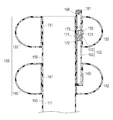
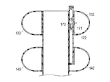
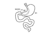
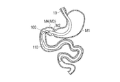
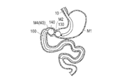
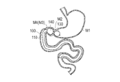
- FIG. 2 is a cross-sectional view taken along line 2-2 in FIG. It is sectional drawing for demonstrating operation
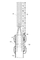
- It is the schematic which shows the device installation system for digestive tracts for installing the device for digestive tract concerning 1st Embodiment in a digestive tract. It is sectional drawing which shows the time of connecting a holding member and a supply pipe
- FIG. 26 is a cross-sectional view taken along line 26-26 in FIG. It is sectional drawing which shows the cylinder part of the device for digestive tracts concerning 5th Embodiment. It is a schematic sectional drawing which shows a part of digestive tract. It is a schematic sectional drawing which shows the state which inserted the device for digestive tracts through the endoscope inside the digestive tract.
- the gastrointestinal tract device 100 is used to orally or nasally insert into the digestive tract and leave it to cover a part of the digestive tract. It is a device that circulates so that it does not come into contact with the covered part. As shown in FIGS. 1 and 2, the gastrointestinal tract device 100 is formed in a tubular shape and includes a flexible tubular portion 110 having a through hole 111, and one end side (a proximal end side) of the tubular portion 110 in the penetration direction. And an indwelling unit 120 provided.
- the side on which the cylindrical portion 110 is provided is referred to as the distal end side
- the side on which the indwelling portion 120 is provided is referred to as the proximal end side
- the anal side is referred to as the distal side
- the oral cavity side is referred to as the proximal side.
- the cylinder part 110 is formed of a film-like member that can be flexibly deformed according to the movement of the digestive tract.
- the cylinder part 110 has an outer diameter slightly smaller than the inner diameter of the upper part of the small intestine to be installed. Although the outer diameter of the cylinder part 110 is substantially constant in the penetration direction of the through hole 111 of the cylinder part 110, it does not necessarily have to be constant.
- the thickness of the cylindrical portion 110 is preferably 0.002 mm to 0.02 mm, the outer diameter of the cylindrical portion 110 is preferably 10 mm to 60 mm, and the length of the cylindrical portion 110 in the penetration direction is preferably 600 mm. Although it is ⁇ 1300 mm, the dimensions of the cylindrical portion 110 are not necessarily limited to these.
- the cylindrical portion 110 is formed of polytetrafluoroethylene (PTFE) in this embodiment, but the material is not limited as long as it can be flexibly deformed.
- PTFE polytetrafluoroethylene
- the material is not limited as long as it can be flexibly deformed.
- polyethylene, silicone resin, polyurethane, or the like may be used. Good.
- the dimension of the cylinder part 110 mentioned above can be changed suitably.
- the indwelling part 120 includes a first extension part 130 and a second extension part 140 that are arranged along the penetrating direction of the cylindrical part 110, a connecting part 150 that connects the first extension part 130 and the second extension part 140, and a first extension. And an inflow part 160 through which a fluid flows into the part 130 and the second expansion part 140.
- the fluid is, for example, physiological saline, but may be another liquid, a gas such as air, a liquid or a solid dispersed in a gas, or an aggregate of particles.
- the connecting portion 150 is formed in a cylindrical shape integrally with the cylindrical portion 110 by the same material as the cylindrical portion 110.
- the diameter of the connecting portion 150 is the same as the diameter of the cylindrical portion 110 in the present embodiment, but may be different from the diameter of the cylindrical portion 110.
- the connection part 150 may be formed with the other member different from the cylinder part 110, for example, may be integrally formed with the 1st expansion part 130 and the 2nd expansion part 140 with the same raw material.
- the connection part 150 may not be cylindrical, for example, may be provided only in a part of the circumferential direction, or may be provided by being divided into a plurality of parts in the circumferential direction.
- the first expansion portion 130 is an annular balloon disposed on the proximal end side of the connection portion 150, and the first hole portion 131 at the center of the ring communicates with the through hole 111 of the cylindrical portion 110.
- a first inflow space 132 into which a fluid supplied from the outside can flow in through the first inflow hole 133 is formed inside the first expansion portion 130.
- the first hole 131 forms a space into which food flows, and plays a role of guiding food to a second hole 141 of the second expansion part 140 and a through hole 111 of the cylinder part 110 described later.
- the second expansion portion 140 is an annular balloon disposed on the distal end side of the connecting portion 150, and the second hole portion 141 at the center of the ring communicates with the through hole 111 of the cylindrical portion 110.
- a second inflow space portion 142 into which a fluid supplied from the outside can flow in via the second inflow hole 143 is formed inside the second expansion portion 140.
- the second hole 141 forms a space where food flows in from the first hole 131 of the first expansion part 130, and plays a role of guiding the food to the through hole 111 of the cylinder part 110.
- the first extension part 130 and the second extension part 140 are formed of an elastically deformable silicone resin.
- the first extension 130 and the second extension 140 may be formed of other elastically deformable elastic materials such as natural rubber and fluorosilicone polymer.
- the first expansion part 130 can be expanded to an outer diameter of preferably about 5 mm to 60 mm by expansion, the length is preferably 30 mm to 50 mm, and the second expansion part 140 can be expanded by expansion.
- the diameter is preferably expandable to about 10 mm to 50 mm
- the length is preferably 30 mm to 50 mm
- the distance between the first expansion portion 130 and the second expansion portion 140 is preferably 10 mm to 60 mm.
- the dimensions of the first extension 130 and the second extension 140 are not necessarily limited thereto.
- the inflow part 160 allows the inflow of the fluid from the outside, and expands the backflow prevention part 161 for preventing the backflow of the fluid once inflow and the second expansion part 140 before the first expansion part 130.
- an adjustment unit 162 that adjusts the flow of fluid from the outside is provided.
- the backflow prevention unit 161 is a duckbill check valve that allows inflow of fluid from the outside and prevents backflow of the fluid that has once flowed in. However, it is possible to prevent backflow of the fluid that has flowed in from the outside.
- the structure is not limited.
- the adjustment unit 162 includes a flow channel pipe 163 (flow channel unit) extending from the base end side of the first expansion unit 130 to the second expansion unit 140, and a flow channel to the first expansion unit 130 and the second expansion unit 140. And a flow path switching unit 170 for switching between.
- a flow channel pipe 163 flow channel unit
- the flow channel pipe 163 is located in the vicinity (inner peripheral side) of the holes of the first extension part 130 and the second extension part 140, and the fluid supplied from the outside is supplied to the first extension part 130 and the second extension part 140. It is a guiding tube.
- the channel tube 163 is formed of a silicone resin, a fluoro-silicone polymer, or the like, but the material is not particularly limited.
- the channel switching unit 170 is provided in the middle of the channel tube 163, and the first channel 171 that guides the fluid to the first inflow hole 133 of the first expansion unit 130 and the second channel of the second expansion unit 140.
- a second flow path 172 that guides the fluid to the inflow hole 143, a switching member 173 that moves according to the pressure of the fluid, and an elastic member 174 that biases the switching member 173 are provided.
- the switching member 173 is biased to a position that closes the flow path 160 and the flow path between the first flow path 171 and the second flow path 172 in a state where the supply of the fluid is stopped, and the pressure of the fluid 3, the elastic member 174 biases the first flow path 171 and opens the second flow path 172 as shown in FIG.
- the pressure of the fluid rises. As shown in FIG. 4, it is configured to move to a position where it is pushed by the fluid to close the second flow path 172 and open the first flow path 171. That is, when the pressure of the fluid is low, the second expansion unit 140 expands and the first expansion unit 130 expands by increasing the pressure. Moreover, the structure which can open both the 1st flow path 171 and the 2nd flow path 172 by adjustment of the pressure of a fluid may be sufficient. Further, in a state where the supply of the fluid is stopped, the switching member 173 has a position where the first flow path 171 is closed, a position where the second flow path 172 is closed, or between the first flow path 171 and the second flow path 172. It may be biased to a position that closes the flow path.
- an endoscope 10 When installing the digestive tract device 100, as shown in FIGS. 5 and 6, an endoscope 10, a display device 20, a fluid supply device 30 and a gripping device 40 are used. That is, the digestive tract device 100, the endoscope 10, the display device 20, the fluid supply device 30, and the gripping device 40 constitute a digestive tract device installation system for installing the digestive tract device in the digestive tract.
- the endoscope 10 includes an image sensor 11 composed of a CCD sensor or the like for performing imaging, and a channel 12 for inserting the digestive tract device 100 into a living body.
- the endoscope 10 is not particularly limited in configuration as long as a general one can be used and imaging can be performed and the digestive tract device 100 can be inserted.
- the display device 20 includes a monitor that displays an image acquired by the endoscope 10.
- the fluid supply device 30 includes a pressurization device 31 capable of supplying physiological saline as a fluid at an arbitrary pressure, one end connected to the pressurization device 31, and the fluid circulates, and the other end for the digestive tract.
- a supply pipe 32 that can be liquid-tightly connected to the inflow portion 160 of the device 100 is provided.
- the gripping device 40 is a device that grips the digestive tract device 100 and moves it to a predetermined position, then releases the grip and positions the digestive tract device 100 at a predetermined position.
- an operation unit 42 including a lever 41 is provided on the proximal side of the gripping device 40.
- the digestive tract device 100 is gripped or gripped by a gripping member 43 provided at the tip of the gripping device 40. Can be released (see the dashed line in FIG. 6).
- grip apparatus 40 is not specifically limited, For example, a balloon can also be used.
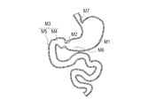
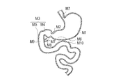
- the part where the gastrointestinal device 100 is installed is in the vicinity of the pyloric ring M2 in the gastrointestinal tract.
- the pyloric ring M2 is located between the stomach M1 and the duodenum M3, and has an inner diameter smaller than that of the stomach M1 and the duodenum M3.
- the duodenum M3 has a duodenal bulb M4 adjacent to the stomach M1 through the pyloric ring M2, and has a descending duodenum M5 having a smaller inner diameter than the duodenum bulb M4 on the distal side of the duodenum bulb M4.
- the stomach M1 contracts to become thin when it is empty, and expands to expand its diameter when food is ingested.
- the food is agitated by the contraction wave of the stomach M1, and the food is digested by the gastric juice to be transported to the distal side while producing a cocoon-like degradation product.
- the pyloric vestibule M6 secretes alkaline mucus, neutralizes acidic cocoon-like degradation products, and when the degradation products become alkaline, the sphincter of the pyloric ring M2 loosens and opens the pyloric ring M2, and the intestinal gut Movement occurs.
- the degradation product is sent to the duodenum M3 through the pyloric ring M2 by contraction of the pyloric vestibular part M6 below the stomach M1.
- the duodenum M3 conveys the decomposition product to the distal side while stirring, by intestinal movement including peristaltic movement, segmental movement, and pendulum movement.
- the endoscope 10 When installing the gastrointestinal tract device 100, first, the endoscope 10 is inserted through the mouth or nose, and as shown in FIG. 8, until the distal end of the endoscope 10 passes through the pylorus M2 while checking the image. Move forward. The distal end of the endoscope 10 that has passed through the pyloric ring M2 is located in the duodenum M3. If the digestive tract device 100 can be inserted from the stomach M1 side through the pyloric ring M2 to the duodenum M3 side, the distal end of the endoscope 10 does not necessarily have to pass through the pyloric ring M2.
- the cylindrical portion 110 of the gastrointestinal tract device 100 is folded, the first expansion portion 130 and the second expansion portion 140 are contracted, and the inflow portion 160 is connected to the supply pipe 32 connected to the pressurizing device 31 (see FIG. 5). ).
- the digestive tract device 100 is gripped by the gripping device 40, the digestive tract device 100 is inserted into the channel 12 of the endoscope 10, and the digestive tract device 100 is moved to the distal end side by operating the gripping device 40.
- the gastrointestinal device 100 connected to the grasping device 40 and the supply tube 32 may be inserted into the channel 12 in advance before the endoscope 10 is inserted from the mouth or nose.
- the digestive tract device 100 is protruded from the distal end of the endoscope 10 into the duodenum M3.
- the gastrointestinal device 100 reaches the distal side of the duodenal bulb M4 adjacent to the pyloric ring M2 or the duodenal bulb M4, the folded cylinder 110 extends distally by the peristaltic movement of the duodenum M3.
- an auxiliary member may be temporarily fixed to the distal end side of the cylindrical portion 110 in order to promote extension of the cylindrical portion 110 due to peristaltic movement.
- the auxiliary member is, for example, a spherical member. The auxiliary member receives a force toward the distal side by a peristaltic motion, and extends the cylindrical portion 110. Withdrawal and finally excreted.
- an adhesive may be used or engaged so as to be released with a predetermined force.
- the pressurizer 31 is operated to supply the fluid to the digestive tract device 100.
- the pressure of the fluid is adjusted to a low pressure such that the switching member 173 of the flow path switching unit 170 closes the first flow path 171 and keeps the second flow path 172 open (see FIG. 3). ). Therefore, the fluid that has reached the digestive tract device 100 via the supply pipe 32 first enters the flow path pipe 163 through the backflow prevention unit 161 and then passes through the second flow path 172 of the flow path switching unit 170 to the second. It flows into the second inflow space 142 of the expansion part 140. Then, as shown in FIG. 10, the second expansion unit 140 is expanded while confirming the image obtained by the endoscope 10, and the second expansion unit 140 expands to a size that cannot pass through the pylorus ring M2. The pressure device 31 is operated to temporarily stop the supply of the fluid.
- the grasping device 40 is moved backward together with the endoscope 10 until the second expansion unit 140 contacts the pylorus M ⁇ b> 2.
- the gastrointestinal device 100 is retracted.
- the gastrointestinal device 100 no longer retracts, so that the operator can ensure that the second extension 140 comes into contact with the pyloric ring M2 by a hand sense and image. Therefore, accurate positioning is possible.
- the second expansion portion 140 is fitted into the duodenal bulb M4, and the unexpanded first expansion portion 130 moves from the duodenum M3 side to the stomach M1 side through the pylorus ring M2. .
- the 1st expansion part 130 and the 2nd expansion part 140 are positioned correctly so that the pylorus ring M2 may be pinched
- the pressurizer 31 is operated to supply the fluid to the digestive tract device 100 again.
- the pressure of the fluid causes the switching member 173 of the flow channel switching unit 170 to block the first flow channel 171 and the second flow channel. 172 is adjusted to a low pressure that maintains the open state (see FIG. 3). Therefore, the fluid flows into the second inflow space 142 of the second expansion part 140 through the second flow path 172 of the flow path switching unit 170.
- the second expansion unit 140 is further expanded while confirming the image obtained by the endoscope 10, and the second expansion unit 140 is expanded to an appropriate size for placement in the duodenal bulb M4. The pressure of the fluid is increased by the device 31.
- the pressure of the fluid at this time is a predetermined pressure at which the switching member 173 moves so that the switching member 173 of the channel switching unit 170 moves and the second channel 172 is closed and the first channel 171 is opened. (See FIG. 4).
- the fluid does not flow into the second extension portion 140 on the distal side, but passes through the first flow path 171 of the flow path switching portion 170 to the first inflow of the first extension portion 130 on the proximal side. It flows into the space part 132.
- the first expansion unit 130 is expanded while confirming the image obtained by the endoscope 10, and the first expansion unit 130 has a desired size that is larger than the size that the first expansion unit 130 cannot pass through the pylorus ring M2.
- the pressurizing device 31 is operated to stop the supply of the fluid.
- the first expanded portion 130 that is expanded larger than the inner diameter of the pyloric ring M2 is positioned closer to the proximal side than the pylorus M2, the second expanded portion 140 is fitted into the duodenal bulb M4, and the first expanded portion.
- the pylorus M2 is sandwiched between the 130 and the second expansion part 140. Therefore, the digestive tract device 100 is firmly placed in the digestive tract.
- the second dilator 140 is expanded to some extent, the digestive tract device 100 is retracted and the second dilator 140 is brought into contact with the pyloric ring M2, and then the second dilator 140 is expanded again. If the expansion of the second expansion unit 140 before the gastrointestinal device 100 is retracted is sufficient, the expansion of the first expansion unit 130 may be started without further expanding the second expansion unit 140.
- the supply pipe 32 is pulled to separate the supply pipe 32 from the inflow portion 160 of the digestive tract device 100. Even if the supply pipe 32 is removed, the gastrointestinal device 100 is provided with the backflow prevention unit 161, so that the fluid inside the gastrointestinal device 100 does not leak, and the first expansion unit 130 and the second expansion unit are not leaked. The state where the section 140 is expanded is maintained. Thereafter, the operation unit 42 of the grasping apparatus 40 is operated to release the grasping of the digestive tract device 100 (see the one-dot chain line in FIG. 6). Then, as shown in FIG. 13, the endoscope 10, the grasping device 40, and the supply tube 32 are pulled out from the digestive tract, and the procedure is completed.
- the connection part 150 located inside the pyloric ring M2 can be flexibly deformed and does not hinder the opening and closing of the pyloric ring M2.
- the cylinder part 110 can be deform
- the decomposition product which flowed into the inside of the cylinder part 110 is pushed out to the distal side, being stirred by the intestinal movement of the duodenum M3.
- the nutrients are not in direct contact with the duodenum M3 and the jejunum upper part of the small intestine covered with the tube part 110, and the absorption of the nutrient is performed after the food passes through the tube part 110.
- GIP, glucagon, and the like are considered to be factors that decrease insulin secretion. When these are not secreted, insulin secretion is not inhibited, and the blood glucose level can be decreased by insulin. When undigested food reaches the lower jejunum and ileum of the small intestine, the stimulation by nutrients increases the secretion of GLP-1, a gastrointestinal hormone that is considered to be a factor promoting insulin secretion. Secretion can be further promoted to reduce blood glucose levels.
- the digestive tract device 100 in the digestive tract, the digestion and absorption of nutrients are reduced and the blood sugar level is reduced, which is highly effective in the treatment of diabetes (particularly type 2 diabetes) and obesity.
- the present invention provides a device for gastrointestinal tract having a cylindrical portion provided at one end with a first dilation portion and a second dilation portion, orally or nasally in a state where the first dilation portion and the second dilation portion are contracted.
- the second dilatation part distal to the first dilation part is located farther from a specific site in the gastrointestinal tract (in this embodiment, the pylorus); Expanding the digestive tract device proximally to bring the second extension into contact with the specific site; expanding the first extension proximal to the specific site; A method of indwelling in the digestive tract is also provided.
- the method includes treating, curing, reducing, alleviating, changing, improving, improving, recovering, enhancing or acting on the disease or symptom of these patients in use against diabetes or obesity.
- part in which the 1st expansion part 130 and the 2nd expansion part 140 are indwelled is a site
- a pylorus Although it is the ring M2, for example, as will be described later, it may be the cardia M7 (see FIG. 33) above the stomach M1, or may be installed at other sites in the digestive tract.
- the gastrointestinal tract device 100 includes the first expansion unit 130 and the second expansion unit 140 that can be expanded by the flow of a fluid supplied from the outside, and the first expansion unit 130. Since the second expansion section 140 is provided with a flow path switching section 170 that adjusts the flow of the fluid from the outside so as to expand the second expansion section 140 first, when the digestive tract device 100 is installed in the digestive tract, Only the distal second extension 140 can be expanded without expanding the distal first extension 130. Therefore, after expanding only the second expansion portion 140 on the distal side of the actual installation location, the gastrointestinal device 100 is retracted, so that the second expansion portion 140 is installed at a small inner diameter such as the pyloric ring M2. Can be positioned.
- the operator can reliably detect that the first expansion unit 130 is in contact with the pylorus M2 based on the sense of the hand and the image of the endoscope 10, and easy and accurate positioning is possible. It becomes possible. This eliminates the need for X-ray observation in the placement of the gastrointestinal device 100, improves operability and reduces the burden on the patient.
- the 1st expansion part 130 and the 2nd expansion part 140 are the structures expanded by inflow of a fluid, it can be expanded so that it may adapt to the shape of a biological body, and the individual difference of a biological body can be absorbed. At the same time, more secure detention is possible. Therefore, even if the stomach M1, the duodenum M3, and the like perform peristaltic movement, the gastrointestinal device 100 is hardly detached and difficult to be displaced by receiving the force received from the living body.
- an anchor member a member for fixing the position
- the first expansion portion 130 and the second expansion portion 140 can be flexibly deformed. It is possible to disperse without concentrating locally, and it becomes difficult for the living body to recognize it as a foreign object. For this reason, it becomes difficult to produce the inflammation of a biological tissue, and the burden on a biological body can be reduced.
- first expansion part 130, the second expansion part 140 and the cylinder part 110 can be deformed flexibly while dispersing the force, the movement of the digestive tract is not limited, and the movement of the digestive tract is followed, Degradation products can be conveyed. Therefore, it is possible to suppress undigested degradation products from rapidly reaching the distal side of the digestive tract device 100, and to suppress abdominal pain and nausea.
- the 1st expansion part 130 and the 2nd expansion part 140 are expanded with the fluid, when removing the device 100 for gastrointestinal tracts from a gastrointestinal tract, it observes with the endoscope 10 and observes the endoscope 10. Fixation to the gastrointestinal tract can be released simply by breaking the first extension portion 130 and the second extension portion 140 with an instrument inserted through the channel 12, and can be easily removed.
- first expansion portion 130 and the second expansion portion 140 are expanded by the fluid, the first expansion portion 130 and the second expansion portion 140 can be expanded according to the inner diameter of the digestive tract, and the cylindrical portion 110 can be easily cut to a desired length.
- One dimensional standard can support various shapes.
- the adjustment part 162 has the flow-path switching part 170 which switches the state which closed the 1st flow path 171 to the 1st expansion part 130 from the closed state by the change of the pressure of a fluid, it is to the device 100 for digestive tracts.
- the flow path can be switched by changing the pressure of the fluid, the configuration can be simplified, the influence on the living body can be reduced, and the operability can be improved.
- the digestive tract device 200 according to the second embodiment of the present invention is different from the digestive tract device 100 according to the first embodiment in the configuration of the adjustment unit 270.
- symbol is attached
- the adjustment unit 270 of the digestive tract device 200 includes a flow channel 271 and an introduction portion from the flow channel 271 to the first inflow hole 133 of the first expansion portion 130.
- a first valve part 272 (flow path switching part) provided and a second valve part 273 provided in the introduction part from the flow path pipe 271 to the second expansion part 140 are provided.
- the first valve portion 272 and the second valve portion 273 are valve portions that prevent the flow of the fluid when the pressure is lower than a predetermined pressure (open pressure), and allow the flow of the fluid when the pressure is equal to or higher than the open pressure.
- the release pressure of the second valve portion 273 is set lower than the release pressure of the first valve portion 272.
- the 1st valve part 272 and the 2nd valve part 273 are duckbill type check valves which prevent backflow of the fluid which flowed in once, if the opening pressure can be varied, the structure will not be limited.
- a flow path closing device 280 having a flow path closing balloon 281 that can be expanded and contracted can be inserted into the flow path pipe 271 via the supply pipe 32 and the backflow prevention portion 161. .
- the channel closing device 280 can expand the balloon on the distal end side by allowing fluid to flow in from the other end side. In the state where the flow path closing balloon 281 is contracted, the flow of the fluid in the flow path pipe 271 is not hindered. However, when the flow path closing balloon 281 is expanded, the interior of the flow path pipe 271 is blocked and the fluid is flown. Distribution is hindered.
- the flow path closing device 280 can be inserted into the supply pipe 32 by providing an insertion port (not shown) provided with a check valve in the supply pipe 32.
- the endoscope 10 When using the gastrointestinal tract device 200 according to the second embodiment, first, as in the first embodiment, the endoscope 10 is inserted into the duodenum M3 and then connected to the grasping device 40 and the supply tube 32.
- the device 200 for gastrointestinal tract is caused to protrude from the channel 12 of the endoscope 10 into the gastrointestinal tract by operating the grasping device 40.
- a flow path closing balloon 281 in a contracted state is inserted through the supply pipe 32 and the backflow prevention unit 161.
- the pressurizer 31 is operated to supply the fluid to the digestive tract device 200. Since the flow path closing balloon 281 is deflated and the release pressure of the second valve portion 273 is set lower than the release pressure of the first valve portion 272, the fluid is the second valve portion 273 having a low release pressure. And flows into the second inflow space portion 142, and the second expansion portion 140 on the distal side expands. Then, the second expansion unit 140 is expanded while confirming the image obtained by the endoscope 10, and after the second expansion unit 140 expands to a size that cannot pass through the pylorus M2, the pressure device 31 is operated to flow. Stop supplying the body.
- the gastrointestinal device 200 is retracted together with the endoscope 10 until the second dilator 140 comes into contact with the pyloric ring M2. After the second expansion unit 140 comes into contact with the pyloric ring M2, if necessary, a fluid is further supplied to the second expansion unit 140 to expand it to a desired size.
- the flow path closing balloon 281 is expanded between the first valve portion 272 and the second valve portion 273. Thereby, the flow path of the fluid to the 2nd expansion part 140 is interrupted
- the first expanded portion 130 that is expanded larger than the pyloric ring M2 is positioned closer to the proximal side than the pyloric ring M2, and the second expanded portion 140 is fitted to the duodenal bulb M4.
- the gastrointestinal device 200 can be installed so that the pylorus M2 is sandwiched between the first expanded portion 130 and the second expanded portion 140.
- the supply tube 32 is detached from the digestive tract device 100, the gripping by the gripping device 40 is released, the endoscope 10, the gripping device 40, and the supply tube 32 are pulled out from the digestive tract, and the procedure is completed.
- the adjustment unit 270 communicates with the first valve unit 272, the first valve unit 272, and the second expansion unit 140, and the fluid to the second expansion unit 140. Since the flow path pipe 271 capable of disposing the flow path closing device 280 that can close the flow path of the first valve section 272 is provided, the second pressure section 273 is connected to the second valve section 273 through the second valve section 273. After the expansion part 140 is expanded, the first expansion part 130 can be expanded by closing the flow path with the flow path closing device 280.
- the second expansion portion 140 is expanded earlier than the first expansion portion 130 by making the opening pressure of the second valve portion 273 smaller than the first valve portion 272.
- the second valve portion 273 may not be provided.
- the gastrointestinal device 300 according to the third embodiment of the present invention is different from the gastrointestinal device 100 according to the first embodiment in the configuration of the adjustment unit 370.
- symbol is attached
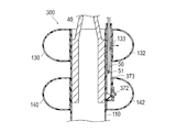
- the adjustment unit 370 of the digestive tract device 300 includes a flow channel tube 373 and a second valve unit provided in the introduction portion from the flow channel tube 373 to the second expansion unit 140. 372 (flow path switching unit).
- the 2nd valve part 372 is a duckbill type check valve which prevents the back flow of the fluid which once flowed in, if the non-return effect is exhibited, a structure will not be limited.
- a tapered portion 374 is formed in the vicinity of the second valve portion 372 of the flow channel tube 373 so that a supply tube 50 described later can be easily inserted into the second inflow space portion 142.
- the supply pipe 50 connected to the pressurizing device 31 can be inserted into and extracted from the second inflow space 142 of the second expansion part 140 via the backflow prevention part 161 and the second valve part 372. .
- An opening 51 for supplying a fluid is formed at the tip of the supply pipe 50.
- the endoscope 10 is inserted into the duodenum M3 and then connected to the grasping device 40 and the supply tube 50.
- the gastrointestinal tract device 300 is caused to protrude from the channel 12 of the endoscope 10 into the digestive tract by operating the grasping device 40.
- the distal end portion of the supply pipe 50 is inserted into the second inflow space 142 through the backflow prevention part 161, the flow pipe 373 and the second valve part 372 in the digestive tract device 300.
- the pressurizer 31 is operated to supply the fluid to the digestive tract device 300. Since the distal end portion of the supply pipe 50 is inserted into the second inflow space portion 142, the fluid flows directly into the second inflow space portion 142, and the second extension portion 140 on the distal side flows. Expand. Then, after confirming the image obtained by the endoscope 10, the second expansion unit 140 is expanded, and after the second expansion unit 140 expands to a size that cannot pass through the pylorus ring M2, the pressurizing device 31 is operated. The fluid supply is temporarily stopped.
- the digestive tract device 300 is retracted together with the endoscope 10 until the second dilator 140 comes into contact with the pyloric ring M ⁇ b> 2. After the second expansion unit 140 comes into contact with the pylorus M2, if necessary, a fluid is further supplied to the second expansion unit 140 to expand it to a desired size.
- the supply pipe 50 is retracted, and the opening 51 is pulled out from the second valve part 372 and positioned in the flow path pipe 373.
- the fluid does not flow into the second expansion portion 140 because the second valve portion 372 is provided. It flows into the first inflow space part 132 of the one expansion part 130.
- the first expansion unit 130 is expanded, and the first expansion unit 130 is expanded to a desired size that is larger than the size that cannot pass through the pylorus ring M ⁇ b> 2. 31 is operated to stop the fluid supply.
- the first expanded portion 130 that is expanded larger than the pyloric ring M2 is positioned closer to the proximal side than the pyloric ring M2, and the second expanded portion 140 is fitted to the duodenal bulb M4.
- the gastrointestinal device 300 can be installed so that the pyloric ring M2 is sandwiched between the first expansion part 130 and the second expansion part 140.
- the supply tube 50 is pulled out from the digestive tract device 100, the gripping by the gripping device 40 is released, and the endoscope 10, the gripping device 40, and the supply tube 50 are pulled out from the digestive tract, and the procedure is completed.
- the adjustment part 370 is provided in the flow path to the second expansion part 140, and the first valve part 372 into which the supply pipe 50 can be inserted and withdrawn, and the first The supply pipe 50 is connected via the second valve part 372 to the expansion part 130 and the second valve part 372 and includes a flow path pipe 373 in which the supply pipe 50 drawn from the second valve part 372 can be arranged. After inserting the second expansion part 140 to expand the second expansion part 140, the supply pipe 50 is pulled out from the second valve part 372 and disposed in the flow path pipe 373 to expand the first expansion part 130. it can.
- the second valve portion 372 does not necessarily need to be able to completely prevent the fluid from flowing into the first expansion portion 130 when the second expansion portion 140 is expanded. Even if it is only the 2nd inflow hole 143 by which the supply pipe
- the gastrointestinal device 400 according to the fourth embodiment of the present invention differs from the gastrointestinal device 100 according to the first embodiment in the configuration of the adjustment unit 470.
- symbol is attached
- the adjustment unit 470 of the gastrointestinal tract device 400 includes a flow path pipe 473 and a first valve section provided in the introduction section from the flow path pipe 473 to the first expansion section 130. 471 (flow path switching unit).
- the first valve portion 471 prevents the flow of the fluid when the pressure is lower than a predetermined pressure (open pressure), and allows the flow of the fluid when the pressure is equal to or higher than the open pressure, and prevents the back flow of the fluid once flowed.
- a predetermined pressure open pressure
- mold check valve if an opening pressure can be set, a structure will not be limited.
- the first valve portion a structure in which the flow of the fluid is hindered when the pressure is less than a predetermined value and the flow path is irreversibly opened due to separation or breakage when the pressure exceeds the predetermined value is applied.
- the endoscope 10 is inserted to the duodenum M3 and then connected to the grasping device 40 and the supply tube 32.
- the digestive tract device 400 is operated by operating the grasping device 40 to protrude from the channel 12 of the endoscope 10 into the digestive tract.
- the pressurizer 31 is operated to supply the fluid to the digestive tract device 400.
- the first valve portion 471 is provided in the first expansion portion 130, the fluid does not flow in, the fluid flows into the second inflow space portion 142 of the second expansion portion 140, and the second The expansion unit 140 expands.
- the second expansion unit 140 is expanded, and after the second expansion unit 140 expands to a size that cannot pass through the pylorus ring M2, the pressurizing device 31 is operated. The fluid supply is temporarily stopped.
- the gastrointestinal device 400 is retracted together with the endoscope 10 until the second dilator 140 comes into contact with the pylorus ring M2.
- the second inflow space 142 is filled with the fluid and the pressure of the fluid rises.
- the pressure of the fluid becomes equal to or higher than the opening pressure of the first valve portion 471
- the fluid flows into the first inflow space portion 132 via the first valve portion 471.
- the first expansion unit 130 is expanded, and the first expansion unit 130 is expanded to a desired size that is larger than the size that cannot pass through the pylorus ring M ⁇ b> 2.
- 31 is operated to stop the fluid supply.
- the first expanded portion 130 that is expanded larger than the pylorus ring M2 is positioned on the proximal side of the pylorus M2, and the second expanded portion 140 is fitted to the duodenal bulb M4. Furthermore, the gastrointestinal device 400 can be installed so that the pylorus ring M2 is sandwiched between the first extension 130 and the second extension 140.
- the supply tube 32 is detached from the digestive tract device 100, the gripping by the gripping device 40 is released, the endoscope 10, the gripping device 40, and the supply tube 32 are pulled out from the digestive tract, and the procedure is completed.
- the first valve unit that prevents the fluid from flowing in until the adjustment unit 470 is provided in the flow path to the first expansion unit 130 and exceeds a predetermined release pressure.
- the second expansion portion 140 is supplied by supplying fluid at a pressure lower than the release pressure of the first valve portion 471.
- the first expansion portion 130 can be expanded by a fluid having a pressure higher than the release pressure of the first valve portion 471.
- the covering portion 511 may be formed by folding back the material constituting the cylindrical portion 510 so as to cover the indwelling portion 120.
- the material of the cylindrical portion 510 for example, polytetrafluoroethylene
- the first expanded portion 130 and the second expanded portion 140 for example, silicone resin
- uneven shapes may be formed on the surfaces of the first extension portion 630 and the second extension portion 640.
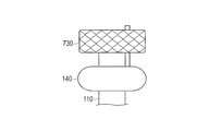
- the first expansion portion 730 can be composed of a plurality of elastic wires that self-expand so as to return elastically by being pushed out from the channel 12 of the endoscope 10. In such a configuration, only the second extension portion 140 protrudes from the channel 12 of the endoscope 10, and after the second extension portion 140 is extended, the first extension portion 730 protrudes from the channel 12.
- the first expansion unit 730 can be expanded.
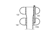
- the flow path pipe 163 may serve as a connection between the first expansion section 130 and the second expansion section 140 without providing the connection section 150.
- the cylinder part 110 ⁇ / b> A is provided from the first extension part 130, and the decomposition product can be smoothly transferred to the duodenum side M ⁇ b> 3 without being caught by the flow channel pipe 163.
- the cylinder part 110 ⁇ / b> B may be provided from the second extension part 140 without providing the connecting part 150.
- the first cylindrical portion 110 ⁇ / b> C and the second cylindrical portion 110 ⁇ / b> D are connected from both the first extended portion 130 and the second extended portion 140 without providing the connecting portion 150. It may be provided individually.
- the distal end side of the first cylinder part 110 ⁇ / b> C provided in the first extension part 130 is positioned inside the second cylinder part 110 ⁇ / b> D provided in the second extension part 140.
- the decomposition product passes through the first cylinder part 110C provided in the first extension part 130, and the decomposition product is caught on the flow path pipe 163.
- the digestive tract device 500 according to the fifth embodiment of the present invention is capable of introducing digestive fluid secreted in the living body into the cylindrical portion. Different from the gastrointestinal device according to the fourth embodiment.
- symbol is attached
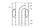
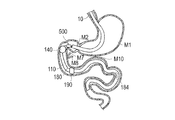
- a digestive tract device 500 includes a flexible cylindrical portion 110 having a through hole 111 and one end side (base end side) of the cylindrical portion 110 in the penetration direction. ), An indwelling part 120 for indwelling the cylinder part 110 in the living body, an opening part 180 formed in the cylinder part 110 and allowing digestive juice secreted in the living body to flow into the through-hole 111, and the opening part 180 And a guide unit 190 for guiding the digestive juice.
- the gastrointestinal device 500 will be described through an embodiment in which an opening 180 and a guide 190 are added to the gastrointestinal device 100 according to the first embodiment. However, although explanation is omitted, it is also possible to adopt a form in which the opening 180 and the guide part 190 are applied to the digestive tract device according to the second to fourth embodiments.
- the indwelling unit 120 is a connection that connects the first expansion unit 130 and the second expansion unit 140, and the first expansion unit 130 and the second expansion unit 140 that are arranged along the penetration direction of the cylindrical unit 110. Part 150 and an inflow part 160 for allowing the fluid to flow into the first extension part 130 and the second extension part 140.
- the gastrointestinal device 500 has an opening 180 opened on the side surface of the cylindrical portion 110.
- the cylinder part 110 has an inner cylinder 181 that communicates from the opening 180 to the inside of the cylinder part 110.
- the inner cylinder 181 has a digestive fluid lumen 182 into which the digestive fluid flows, and an outflow portion 184 through which the digestive fluid flowing in the digestive fluid lumen 182 flows into the cylindrical portion 110.
- the inner cylinder 181 is capable of taking digestive fluid such as bile and pancreatic juice secreted in the duodenum where the digestive tract device 500 is placed from the opening 180 and allowing the digestive fluid to flow out at a predetermined position in the cylindrical portion 110. It is provided to make it.
- the outflow part 184 is configured by the opening at the tip of the inner cylinder 181, but an opening functioning as an outflow part may be formed on the side surface of the inner cylinder 181. Further, the outflow portion 184 of the inner cylinder 181 may be formed on the distal end side with respect to the distal end side end portion 112 of the cylindrical portion 110. In this case, the digestive juice flowing down the digestive fluid lumen 182 and the food are mixed outside the living body.
- the opening 180 is disposed on the distal side of the duodenal papilla M9 when the digestive tract device 500 is placed in the living body (see FIGS. 28 and 31).
- Digestive fluid such as bile supplied from the bile duct M7 and pancreatic juice supplied from the pancreatic duct M8 is secreted into the duodenum via the duodenal papilla M9.
- the opening 180 by disposing the opening 180 on the distal side of the duodenal papilla M9, it becomes possible to efficiently introduce the digestive fluid into the digestive lumen 182 of the inner cylinder 181 through the opening 180. .
- the through-hole 111 of the cylinder part 110 functions as a food lumen 183 into which an introduction such as food flowing down through the through-hole 111 of the indwelling part 120 is introduced.
- the guide part 190 can be constituted by a closing member that is arranged so as to surround the outer periphery of the cylindrical part 110 and prevents the digestive fluid from flowing down.
- the closing member can be constituted by, for example, a known balloon that expands by inflow of fluid and contracts by discharge of fluid.
- the indwelling may be performed with the balloon inflated, or the balloon may be inflated with an inflator or the like after indwelling in the living body.
- the closing member can be configured by, for example, a plate-like member extending radially from the cylindrical portion 110.
- the guide part 190 is disposed closer to the distal end side of the cylinder part 110 than the opening part 180 in order to allow the digestion liquid to stay in the guide part 190 and to guide the retained digestive liquid to the opening part 180. .
- the outflow portion 184 of the inner cylinder 181 is disposed on the base end side (upper side in the drawing) with respect to the distal end opening 112 of the cylinder portion 110.
- the outflow portion 184 is preferably arranged so that the digestive juice flows out more distally than the position of the duodenojejunum M10 when the digestive tract device 500 is placed in the living body (see FIG. 31). .
- the operation of installing the digestive tract device 500 can be performed using the digestive tract device installation system described in the first embodiment (see FIGS. 5 and 6).
- the endoscope 10 is advanced until the tip of the endoscope 10 passes through the pylorus ring M2.
- the digestive tract device 500 is protruded from the distal end of the endoscope 10 into the duodenum M3.
- the gastrointestinal device 500 reaches the distal side of the duodenal bulb M4 adjacent to the pyloric ring M2 or the duodenal bulb M4, the folded cylindrical portion 110 extends distally by the peristaltic movement of the duodenum M3. To do.
- the pressurizer 31 is operated to supply the fluid to the digestive tract device 500.
- the pressurization apparatus 31 is operated. To stop the fluid supply.
- the digestive tract device 500 is firmly placed in the digestive tract.
- the supply pipe 32 is pulled to disengage the supply pipe 32 from the inflow portion 160 of the digestive tract device 500.
- the opening 180 for allowing the digestive fluid to flow into the cylindrical portion 110 placed in the duodenum M3 and the guide portion 190 for guiding the digestive fluid to the opening 180 are provided. It is possible to increase the inflow amount of the digestive juice into the cylinder part 110. Thereby, since the quantity of the digestive fluid supplied directly into the duodenum M3 from the bile duct M7 or the pancreatic duct M8 can be reduced, the onset of diarrhea can be prevented. Moreover, since mixing of food and digestive fluid in the cylinder part 110 can accelerate
- the guide part 190 is arranged so as to surround the outer periphery of the cylindrical part 110 and has a blocking member that prevents the digestive liquid from flowing down, the digestive liquid can be smoothly guided into the cylindrical part 110. And the occurrence of diarrhea and dumping can be suitably prevented.
- the digestion fluid lumen 182 communicated with the opening 180 and the digestion fluid flows in, and the inner cylinder 181 including the outflow portion 184 that allows the digestion fluid flowing through the digestion fluid lumen 182 to flow out are configured.
- the position where the introduction product such as food introduced into the tube portion 181 and the digestive juice are mixed can be set to an arbitrary position, and the progress of digestion of food in the tube portion 110 can be adjusted. . For example, by delaying the timing at which digestion is started, the amount of digestion and absorption of nutrients into the living body can be reduced, and the effect on the treatment of diabetes and obesity can be enhanced.
- the outflow part 184 through which the digestive fluid flows out from the digestive fluid lumen 182 allows the digestive juice and the food introduced into the cylinder part 110 from outside the living body when the digestive tract device 100 is placed in the living body.
- an outflow part 184 provided in the inner cylinder 181 mixes an introduction such as food introduced into the cylinder part 110 and the digestive fluid on the anal side of the duodenal jejunum in vivo, the food and digestion Since the liquid is not immediately mixed in the cylinder part 110, the food can be neutralized while suppressing excessive digestion of the food in the cylinder part 110, reducing the digestion and absorption efficiency of the ingested nutrients, The occurrence of damping can be suitably prevented.
- the digestive tract device 600 according to the sixth embodiment of the present invention is different from the digestive tract device 500 according to the fifth embodiment in the configuration of the guide portion.
- symbol is attached
- FIG. 32 is a perspective view showing a digestive tract device according to the sixth embodiment.
- the guide portion 191 of the digestive tract device 600 is formed continuously to the plurality of openings 185, 186, 187, and the cylindrical portion 110 is formed from the openings 185, 186, 187.
- Inclined walls 192, 193, and 194 that incline toward the inner side.
- the inclined walls 192, 193, 194 are connected to each other through ribs 195, 196, 197, and are formed integrally with the cylinder part 110.
- Each rib 195, 196, and 197 can be comprised by the rod-shaped member extended radially from the cylinder part 110 so that it may show in figure, for example.
- the digestive fluid is guided to the openings 185, 186, 187 and flows down along the inner surfaces of the inclined walls 192, 193, 194 to the front end side in the longitudinal direction. Introduced substances such as food flowing down through the cylinder part 110 are mixed with the digestive juice in the guide part 191. Even if the digestive juice cannot be captured by the inclined wall 192 located on the most proximal side, the digestive juice can be captured by the other inclined walls 193 and 194, so that the digestive juice and the food can be mixed reliably. This makes it possible to prevent the occurrence of diarrhea and damping.
- the number of installations can be increased or decreased as appropriate without being limited to three.
- the rib was shown to be formed in a radial shape, the rib is not limited to this and can be formed in other shapes.
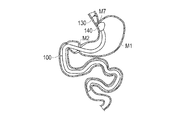
- FIG. 33 shows a modification of the indwelling position of the digestive tract device.
- the pyloric ring M2 is sandwiched between the first expanded part 130 and the second expanded part 140 that are expanded in the vicinity of the pyloric ring M2, and thereby the digestive tract device 100 is placed in the living body.
- the position where the first expansion unit 130 and the second expansion unit 140 are disposed may be, for example, the cardia M7 positioned on the upper side of the stomach M1.
- the amount of food or other introduced substance introduced into the living body through the stomach M1 can be reduced, so that digestion and absorption of nutrients in the stomach M1 can be suppressed. Thereby, the therapeutic effect by the device 100 for digestive tract can be improved further.
- the indwelling work is performed in the same manner as in the case of indwelling in the pylorus ring M2.
- the gastrointestinal device 100 is pulled to the proximal side of the cardia M7, and the second extension 140 is hooked on the cardia M7.
- the first extension 130 is expanded on the proximal side of the cardia M7.
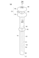
- the gastrointestinal tract device 700 according to the seventh embodiment of the present invention differs from the gastrointestinal tract devices according to the first to sixth embodiments in the positions at which the first expansion portion and the second expansion portion that are indwelling portions are arranged. . Note that members common to the first to sixth embodiments are denoted by the same reference numerals and description thereof is omitted.
- the first expansion portion and the second expansion portion were provided on the proximal end side in the penetration direction of the cylindrical portion, but as shown in FIG.
- the first expansion portion 730 and the second expansion portion 740 constituting the indwelling portion are provided at a predetermined portion between the proximal end and the distal end of the cylindrical portion 710.
- the gastrointestinal device 700 can be placed in the living body by disposing the expanded portions 730 and 740 so as to sandwich the pyloric ring M2.
- the cylinder part 710 has a proximal part 711 provided on the proximal side of the first expansion part 730 and a distal part 713 provided on the distal side of the second expansion part 740.
- the distal portion 713 of the tubular portion 710 can be disposed in the duodenum M3.
- the proximal portion 711 of the tubular portion 710 can be disposed so as to extend further to the upper side than the stomach M1, the cardia M7 located on the upper side (proximal side) of the stomach M1, and the cardia M7. .
- proximal portion 711 of the tubular portion 710 When the proximal portion 711 of the tubular portion 710 is arranged in this manner, an introduced material such as food introduced into the living body flows into the tubular portion 710 on the proximal side of the stomach M1, so that the introduced material is in the stomach.
- the amount passing through M1 decreases. Therefore, digestive absorption of nutrients in the stomach M1 can be suppressed, and the therapeutic effect of the digestive tract device 700 can be further enhanced.
- the length of the proximal portion 711 of the tube portion 710 is not particularly limited, but can be extended to the stomach M1 and the cardia M7 when reducing digestion and absorption of nutrients in the stomach M1 as described above. It is preferable that it is formed in such a length.
- the proximal portion 711 of the tube portion 710 may be configured to be integrally connected to the digestive tract device 700 when the digestive tract device 700 is introduced into the living body, or may be digested in vivo after being introduced into the living body. It is good also as a structure which can be connected with the device 700 for pipes. For example, when the digestive tract device 700 and the proximal portion 711 of the tube portion 710 are integrally formed, the proximal portion 711 of the tube portion 710 can be bent into a bellows shape, and then introduced into the living body. It can be set as the structure which can be extended to the M7 side.
- the digestive tract device 700 and the proximal portion 711 of the tubular portion 710 are configured to be connectable and separable, they can be easily connected or separated by mechanical means such as a screw-in type or a fitting type. It is possible to adopt a configuration that can be used. The connection / separation work can be performed, for example, while confirming an image acquired by the endoscope using the endoscope together. If the configuration is connectable / separable, the device for the digestive tract is placed after indwelling in the living body by connecting or separating the proximal portion 711 according to the symptom of the patient to which the digestive tract device 700 is applied. It is also possible to adjust the effect and effect of 700.
- a shape-memory metal wire or the like is embedded in the proximal portion 711 of the cylindrical portion 710, or a ring-shaped anchor member or the like is installed at the open end of the proximal portion 711 on the cardia M7 side. You can also. If comprised in this way, it will become possible to maintain stably the state (extended state) where the proximal part 711 of the cylinder part 710 stood up toward the cardia M7.
Landscapes
- Health & Medical Sciences (AREA)
- Child & Adolescent Psychology (AREA)
- Obesity (AREA)
- Nursing (AREA)
- Orthopedic Medicine & Surgery (AREA)
- Engineering & Computer Science (AREA)
- Biomedical Technology (AREA)
- Heart & Thoracic Surgery (AREA)
- Vascular Medicine (AREA)
- Life Sciences & Earth Sciences (AREA)
- Animal Behavior & Ethology (AREA)
- General Health & Medical Sciences (AREA)
- Public Health (AREA)
- Veterinary Medicine (AREA)
- Surgical Instruments (AREA)
Description
本発明は、消化管内に設置される消化管用デバイスに関する。
近年、糖尿病(特に2型糖尿病)や肥満の治療方法として、胃の上部と小腸の下部を外科的に直結するバイパス術が有効であることが知られている。このようなバイパス術を行うと、摂取した栄養素が胃の上部から小腸の下部へ直接流れ込むため、小腸上部の十二指腸や空腸上部に栄養素が流れなくなり、栄養の吸収を減少させることができる。さらに、小腸上部に栄養素が流れなくなることで、栄養素の刺激により分泌される消化管ホルモンであるグルコース依存性インスリン分泌刺激ポリペプチド(GIP)やグルカゴン等が分泌され難くなり、かつ未消化の栄養素が小腸下部の空腸下部や回腸を通ることで、栄養素による刺激によって消化管ホルモンであるグルカゴン様ペプチド-1(GLP-1)の分泌が増加する。GIPやグルカゴンは、インスリンの分泌を減少させる因子であると考えられており、これらが分泌されなくなることで、インスリンの分泌が阻害され難くなる。また、GLP-1は、インスリンの分泌を促す因子であると考えられている。このように、バイパス術は、摂取した栄養素の吸収を制限するのみならず、消化管ホルモンの作用によってインスリンの分泌を促して血糖値を減少させ、糖尿病や肥満の治療に効果を発揮すると考えられている。
しかしながら、バイパス術は侵襲性が高いため、近年、小腸上部に栄養素が流れるスリーブを設置する低侵襲な方法が注目されている。例えば特許文献1には、胃の幽門輪を挟むように配置させる2つのバルーンと、このバルーンから小腸へ向かって伸びる筒状のスリーブとを備えたデバイスが記載されている。このデバイスは、経口的に設置可能であるために低侵襲であり、幽門輪に到達した栄養素を、スリーブの内部を通過させることで小腸の上部に触れさせずに小腸の下部へ到達させることができる。
しかしながら、特許文献1に記載のようなデバイスを消化管内に設置する際には、通常、X線により観察しつつ設置する必要があり、操作が煩雑であるとともに、生体への負担が大きい。
本発明は、上述した課題を解決するためになされたものであり、操作性を向上させるとともに生体への負担を低減可能な消化管用デバイスを提供することを目的とする。
上記目的を達成するための消化管用デバイスは、貫通孔を備える筒部と、前記筒部に設けられて外部から供給される流動体が流入することで外径が広がるように拡張可能な第1拡張部と、前記第1拡張部よりも先端側に設けられて外径が広がるように拡張可能な第2拡張部と、前記第1拡張部よりも前記第2拡張部を先に拡張させるように外部からの流動体の流れを調整する調整部と、を有する。
上記のように構成した消化管用デバイスは、第1拡張部よりも第2拡張部を先に拡張させるように外部からの流動体の流れを調整する調整部を有するため、消化管内に設置する際に、第1拡張部よりも遠位側(肛門側)に位置する第2拡張部を先に拡張させることができる。したがって、遠位側の第2拡張部を拡張させた後に、消化管用デバイスを後退させて第2拡張部を消化管内の内径が小さい部位に接触させるだけで位置決めでき、さらに第1拡張部を拡張させることで、消化管用デバイスを消化管内に容易に留置できる。しかも、第2拡張部が消化管内の内径が小さい部位に接触した際に、操作者は手の感覚によって検知でき、X線による観察が不要となり、操作性が向上するとともに生体への負担を軽減できる。
また、前記第2拡張部が、外部から供給される流動体が流入することで外径が広がるように拡張可能であれば、外部からの流動体の流れを第2拡張部から第1拡張部へ調整することで、第1拡張部よりも第2拡張部を先に拡張させることができる。
また、前記調整部が、前記流動体の圧力の変化によって前記第1拡張部への流路を閉鎖した状態から開いた状態に切り換える流路切り換え部を有するようにすれば、流動体の圧力を変化させるだけで、流路の切り換えが可能となり、構成を単純化できるとともに操作性が向上する。
また、前記調整部が、前記第1拡張部への流路に設けられ、所定の解放圧力以上となるまで流動体の流入を妨げる第1弁部と、前記第1弁部および第2拡張部に連通し、第2弁部へ向かう流動体の流路を閉塞可能な流路閉塞用器具を配置可能な流路部と、を有するようにすれば、第1弁部の開放圧力未満の圧力の流動体を供給して第2拡張部を拡張させた後、第1弁部の開放圧力以上の圧力の流動体を供給して第1弁部を介して第1拡張部を拡張させることができる。
また、前記調整部が、前記第2拡張部への流路に設けられ、流動体を供給する供給管を挿入および引き抜き可能な第2弁部と、前記第1拡張部および第2弁部に連通し、前記第2弁部から引き抜かれた供給管を配置可能な流路部と、を有するようにすれば、第2弁部に挿入した供給管により第2拡張部を拡張させた後、第2弁部から供給管を引き抜いて流路部に配置することで、第1拡張部を拡張させることができる。
また、前記調整部が、前記第1拡張部への流路に設けられ、所定の解放圧力以上となるまで流動体の流入を妨げる第1弁部と、前記第1弁部および第2拡張部に連通する流路部と、を有するようにすれば、流路部に第1弁部の開放圧力未満の圧力の流動体を供給することで第2拡張部を拡張させた後、第1弁部の開放圧力以上の圧力となる流動体により、第1拡張部を拡張させることができる。
また、前記筒部が、前記第1拡張部および第2拡張部の少なくとも一方に連結されるようにすれば、第1拡張部側から、若しくは第1拡張部と第2拡張部の間から筒部の貫通孔に食物を円滑に流入させることができる。
また、前記筒部が、前記第1拡張部に連結される第1筒部と、前記第2拡張部に連結される第2筒部と、を有するようにすれば、第1拡張部側から第1筒部の貫通孔に食物を円滑に流入させて第1拡張部と第2拡張部の間に食物が引っかかることを抑制しつつ、第1拡張部と消化管の隙間から漏れ出る一部の食物を、第1拡張部と第2拡張部の間から第2筒部の貫通孔に流入させて、消化管への食物の接触を極力減らすことができる。
また、十二指腸に留置される筒部内へ消化液を流入させるための開口部と、開口部へ消化液を案内するための案内部と、を有するようにすれば、筒部内への消化液の流入量を増加させることができる。これにより、胆管や膵管から十二指腸へ直接供給される消化液を減少させることができるため、下痢の発症を防止することができる。また、筒部内において食物と消化液を混合させることにより、食物の分解を促すことができるため、ダンピングの発症を防止することもできる。
また、案内部を、筒部の外周を囲むように配置され消化液の流下を妨げる閉塞部材を有するようにすれば、筒部内に消化液を円滑に案内することができるため、下痢やダンピングの発症を好適に防止することができる。
また、案内部を、開口部に連なって形成され開口部から筒部の内部に向けて傾斜する傾斜壁を有するようにすれば、筒部内に消化液を円滑に案内することができ、下痢やダンピングの発症を好適に防止することができる。
また、開口部に連通され消化液が流入される消化液用ルーメン、および消化液用ルーメンを流れる消化液を流出させる流出部を備える内筒を有するようにすれば、筒部内へ導入される食物などの導入物と消化液とが混合される位置を任意の位置に設定することができるため、筒部内における食物の消化の進行を調整することができる。例えば、消化が開始されるタイミングを遅らせることにより、生体内への栄養素の消化吸収量を低減させて糖尿病や肥満の治療に対する効果を強めることができる。
また、内筒に設けた流出部によって筒部内に導入された食物などの導入物と消化液とが生体内における十二指腸空腸曲よりも肛門側において混合されるようにすれば、食物と消化液とが筒部内で即座に混合されないため筒部内における食物の過度な消化を抑えつつ食物を中和させることができ、摂取した栄養素の消化吸収効率の低減を図るとともに、下痢やダンピングの発生を好適に防止することができる。
また、第1拡張部および第2拡張部が筒部の貫通方向の基端側に設けられるようにすれば、十二指腸よりも、食物等の導入物の流れの上流側の部位において消化管用デバイスを生体に対して保持させることが可能になるため、長期間に亘る留置をする場合にも脱落が生じることを確実に防止することができる。
また、第1拡張部および第2拡張部が筒部の基端と先端との間の所定の部位に設けられるようにすれば、幽門輪において消化管用デバイスを保持し、かつ、筒部の基端側を胃の上部の噴門側まで延在させることが可能になるため、胃内へ食物等が導入されることを防止できる。
以下、図面を参照して、本発明の実施の形態を説明する。なお、図面の寸法比率は、説明の都合上、誇張されており、実際の比率とは異なる場合がある。
<第1実施形態>
本発明の第1実施形態に係る消化管用デバイス100は、経口的または経鼻的に消化管内に挿入されて消化管の一部を覆うように留置されて、摂食された食物を、消化管の覆われた部位に接触させないように流通させるデバイスである。本消化管用デバイス100は、図1、図2に示すように、筒状に形成されて貫通孔111を備える柔軟な筒部110と、筒部110の貫通方向の一端側(基端側)に設けられる留置部120とを備えている。以下、消化管用デバイス100において、筒部110が設けられる側を先端側、留置部120が設けられる側を基端側と称する。また、消化管内において、肛門側を遠位側、口腔側を近位側と称する。
本発明の第1実施形態に係る消化管用デバイス100は、経口的または経鼻的に消化管内に挿入されて消化管の一部を覆うように留置されて、摂食された食物を、消化管の覆われた部位に接触させないように流通させるデバイスである。本消化管用デバイス100は、図1、図2に示すように、筒状に形成されて貫通孔111を備える柔軟な筒部110と、筒部110の貫通方向の一端側(基端側)に設けられる留置部120とを備えている。以下、消化管用デバイス100において、筒部110が設けられる側を先端側、留置部120が設けられる側を基端側と称する。また、消化管内において、肛門側を遠位側、口腔側を近位側と称する。
筒部110は、消化管の運動に応じて柔軟に変形可能な膜状の部材により形成されている。筒部110は、設置される小腸上部の内径よりも若干小さな外径を有している。筒部110の外径は、筒部110の貫通孔111の貫通方向に略一定であるが、必ずしも一定でなくてもよい。
筒部110の厚さは、好ましくは0.002mm~0.02mmであり、筒部110の外径は、好ましくは10mm~60mmであり、筒部110の貫通方向の長さは、好ましくは600mm~1300mmであるが、筒部110の寸法は必ずしもこれらに限定されない。
筒部110は、本実施形態ではポリテトラフルオロエチレン(PTFE)により形成されるが、柔軟に変形可能に形成可能であれば材料は限定されず、例えばポリエチレン、シリコーン樹脂、ポリウレタン等を用いてもよい。なお、筒部110に適用される材料に応じて、上述した筒部110の寸法は、適宜変更され得る。
留置部120は、筒部110の貫通方向に沿って並ぶ第1拡張部130および第2拡張部140と、第1拡張部130および第2拡張部140を連結する連結部150と、第1拡張部130および第2拡張部140の内部に流動体を流入させる流入部160とを備えている。流動体は、例えば生理的食塩水であるが、他の液体、空気等の気体、液体中や気体中に固体が分散したもの、または粒子の集合体等であってもよい。また、流動体を、液体および気体の混合体とすることで、非圧縮性の液体によって強い保持力を維持しつつ、圧縮性の気体によって消化管からの強い圧縮力を吸収する構成としてもよい。
連結部150は、筒部110と同一素材によって筒部110と一体的に筒状に形成されている。連結部150の径は、本実施形態では筒部110の径と同一となっているが、筒部110の径と異なってもよい。なお、連結部150は、筒部110とは異なる他の部材によって形成されてもよく、例えば、第1拡張部130および第2拡張部140と同一素材によって一体的に形成されてもよい。また、連結部150は、筒状でなくてもよく、例えば周方向の一部のみに設けられたり、または周方向に複数に分割して設けられたりしてもよい。
第1拡張部130は、連結部150の基端側に配置される環状のバルーンであり、環の中央の第1孔部131が筒部110の貫通孔111と連通している。第1拡張部130の内部には、外部から供給される流動体が第1流入孔133を介して流入可能な第1流入空間部132が形成されている。第1孔部131は、食物が流入する空間を形成し、後述する第2拡張部140の第2孔部141および筒部110の貫通孔111へ食物を導く役割を果たす。
第2拡張部140は、連結部150の先端側に配置される環状のバルーンであり、環の中央の第2孔部141が筒部110の貫通孔111と連通している。第2拡張部140の内部には、外部から供給される流動体が第2流入孔143を介して流入可能な第2流入空間部142が形成されている。第2孔部141は、第1拡張部130の第1孔部131から食物が流入する空間を形成し、筒部110の貫通孔111へ食物を導く役割を果たす。
第1拡張部130および第2拡張部140は、弾性的に変形可能なシリコーン樹脂により形成される。なお、第1拡張部130および第2拡張部140は、例えば天然ゴム、フルオロ・シリコーン重合体等の弾性的に変形可能な他の弾性材料により形成されてもよい。また、折り畳まれて収縮した状態から、流動体を流入させることで折り畳みを開いて拡張する構成とすることも可能であり、この場合には、第1拡張部130および第2拡張部140は、必ずしも弾性材料でなくてもよい。
第1拡張部130は、拡張することで外径が好ましくは5mm~60mm程度まで拡張可能であり、長さは、好ましくは30mm~50mmであり、第2拡張部140は、拡張することで外径が好ましくは10mm~50mm程度まで拡張可能であり、長さは、好ましくは30mm~50mmであり、第1拡張部130と第2拡張部140との間の間隔は、好ましくは10mm~60mmであるが、第1拡張部130および第2拡張部140の寸法は必ずしもこれに限定されない。
流入部160は、外部からの流動体の流入を許容するとともに、一旦流入した流動体の逆流を防止する逆流防止部161と、第1拡張部130よりも第2拡張部140を先に拡張させるように外部からの流体の流れを調整する調整部162とを備えている。
逆流防止部161は、外部からの流動体の流入を許容するとともに、一旦流入した流動体の逆流を防止するダックビル型逆止弁であるが、外部から流入した流動体の逆流を防止できるのであれば、構造は限定されない。
調整部162は、第1拡張部130の基端側から第2拡張部140まで延在する流路管163(流路部)と、第1拡張部130および第2拡張部140への流路を切り換える流路切り換え部170とを備えている。
流路管163は、第1拡張部130および第2拡張部140の孔部近傍(内周側)に位置し、外部から供給される流動体を第1拡張部130および第2拡張部140へ導く管体である。流路管163は、シリコーン樹脂、フルオロ・シリコーン重合体等により形成されるが、材料は特に限定されない。
流路切り換え部170は、流路管163の途中に設けられており、第1拡張部130の第1流入孔133へ流動体を導く第1流路171と、第2拡張部140の第2流入孔143へ流動体を導く第2流路172と、流動体の圧力に応じて移動する切換部材173と、切換部材173を付勢する弾性部材174とを備えている。切換部材173は、流動体の供給が停止した状態では、流路部160と第1流路171および第2流路172の間の流路を塞ぐ位置に付勢されており、流動体の圧力が低い状態では、図3に示すように、弾性部材174によって第1流路171を塞ぐとともに第2流路172を開く位置に付勢されており、流動体の圧力が上昇することで、図4に示すように、流動体に押されて第2流路172を塞ぐとともに第1流路171を開く位置に移動する構成となっている。すなわち、流動体の圧力が低い場合には第2拡張部140が拡張し、圧力が上昇することで、第1拡張部130が拡張する構成となっている。また、流動体の圧力の調整によって、第1流路171および第2流路172の両方が開くことも可能な構成でもよい。また、流動体の供給が停止した状態では、切換部材173は、第1流路171を塞ぐ位置、もしくは第2流路172を塞ぐ位置、もしくは第1流路171および第2流路172の間の流路を塞ぐ位置に付勢されてもよい。
次に、第1実施形態に係る消化管用デバイス100を、消化管内に設置する方法を説明する。
消化管用デバイス100を設置する際には、図5、図6に示すように、内視鏡10、表示装置20、流動体供給装置30および把持装置40を使用する。すなわち、消化管用デバイス100、内視鏡10、表示装置20、流動体供給装置30および把持装置40は、消化管用デバイスを消化管内に設置するための消化管用デバイス設置システムを構成する。
内視鏡10は、撮像を行うためのCCDセンサ等からなる撮像素子11と、消化管用デバイス100を生体内に挿入するためのチャネル12とを備えている。なお、内視鏡10は、一般的なものを使用でき、撮像が可能であって消化管用デバイス100の挿入が可能であれば、構成は特に限定されない。
表示装置20は、内視鏡10により取得される映像を表示するモニターを備えている。
流動体供給装置30は、流動体である生理的食塩水を任意の圧力で供給可能な加圧装置31と、一端が加圧装置31に連結されて流動体が流通し、他端が消化管用デバイス100の流入部160に対して液密に連結可能な供給管32とを備えている。
把持装置40は、消化管用デバイス100を把持して所定の位置まで移動させた後、把持を解除して消化管用デバイス100を所定の位置に位置決めする装置である。把持装置40の手元側には、レバー41を備える操作部42が設けられ、レバー41を操作することで、把持装置40の先端に設けられる把持部材43により消化管用デバイス100を把持し、または把持を解除することができる(図6の一点鎖線を参照)。なお、把持装置40の構造は、特に限定されず、例えばバルーンを用いることもできる。
消化管用デバイス100を設置する部位は、消化管内の幽門輪M2の近傍である。幽門輪M2は、図7に示すように、胃M1と十二指腸M3との間に位置し、内径が胃M1および十二指腸M3よりも小さくなっている。十二指腸M3は、幽門輪M2を介して胃M1と隣接する十二指腸球部M4を有し、十二指腸球部M4の遠位側に、十二指腸球部M4よりも内径が小さい十二指腸下行部M5を有する。胃M1は、空のときには細くなるように収縮しており、食物が摂取されると、径を広げるように拡張する。そして、胃M1の収縮の波により食物を撹拌するとともに胃液により食物を消化して糜粥状の分解産物としつつ遠位側へ搬送する。幽門前庭部M6は、アルカリ性の粘液を分泌し、酸性の糜粥状の分解産物を中和し、分解産物がアルカリ性となると、幽門輪M2の括約筋が緩んで幽門輪M2を開き、腸の腸動が生じる。そして、胃M1の下部の幽門前庭部M6の収縮によって、分解産物が幽門輪M2を通って十二指腸M3へ送り込まれる。十二指腸M3は、蠕動運動、分節運動および振り子運動を含む腸動により、分解産物を撹拌しつつ遠位側へ搬送する。
消化管用デバイス100を設置する際には、まず、内視鏡10を口または鼻から挿入し、図8に示すように、画像を確認しながら内視鏡10の先端が幽門M2を通過するまで前進させる。幽門輪M2を通過した内視鏡10の先端は、十二指腸M3内に位置する。なお、消化管用デバイス100を胃M1側から幽門輪M2を通して十二指腸M3側へ挿入できるのであれば、内視鏡10の先端は、必ずしも幽門輪M2を通過させなくてもよい。
次に、消化管用デバイス100の筒部110を折り畳み、さらに第1拡張部130および第2拡張部140を収縮させ、加圧装置31に繋がる供給管32に流入部160を連結する(図5参照)。そして、把持装置40により消化管用デバイス100を把持して消化管用デバイス100を内視鏡10のチャネル12に挿入し、把持装置40を押し込むように操作して消化管用デバイス100を先端側へ移動させる。なお、内視鏡10を口または鼻から挿入する前に、把持装置40および供給管32に連結された消化管用デバイス100を予めチャネル12内に挿入しておいてもよい。
そして、内視鏡10により得られる映像を確認しつつ、図9に示すように、消化管用デバイス100を内視鏡10の先端から十二指腸M3内に突出させる。消化管用デバイス100が、幽門輪M2に隣接する十二指腸球部M4または十二指腸球部M4よりも遠位側に到達すると、十二指腸M3の蠕動運動によって、折り畳まれていた筒部110が遠位側へ伸長する。なお、蠕動による筒部110の伸長を促すために、筒部110の先端側に補助部材を仮止めしておいてもよい。補助部材は、例えば球状の部材であり、蠕動運動によって遠位側へ向かう力を受けて筒部110を伸長させ、筒部110が完全に伸長した後に、蠕動運動から受ける力によって筒部110から離脱し、最終的に排泄される。仮止めする際には、接着剤を用いたり、または所定の力で外れるように係合させたりしてもよい。
次に、加圧装置31を操作して流動体を消化管用デバイス100に供給する。このとき、流動体の圧力を、流路切り換え部170の切換部材173が第1流路171を塞ぐとともに第2流路172を開いた状態を維持する程度の低い圧力に調整する(図3参照)。したがって、供給管32を介して消化管用デバイス100に到達した流動体は、まず逆流防止部161を通って流路管163に入り、流路切り換え部170の第2流路172を通って第2拡張部140の第2流入空間部142に流入する。そして、図10に示すように、内視鏡10により得られる映像を確認しながら第2拡張部140を拡張させ、第2拡張部140が幽門輪M2を通り抜け不能な大きさまで拡張した後に、加圧装置31を操作して流動体の供給を一旦停止させる。
次に、図11に示すように、内視鏡10により得られる画像を確認しつつ、第2拡張部140が幽門M2に接するまで内視鏡10とともに把持装置40を近位側へ後退させて、消化管用デバイス100を後退させる。第2拡張部140が幽門輪M2に接すると、消化管用デバイス100はこれ以上後退しなくなるため、操作者は手の感覚および画像によって、第2拡張部140が幽門輪M2に接したことを確実に検知でき、正確な位置決めが可能である。これにより、第2拡張部140が、十二指腸球部M4に嵌った状態となり、拡張していない第1拡張部130は、幽門輪M2を通って十二指腸M3側から胃M1側へ移動することになる。これにより、第1拡張部130および第2拡張部140が、幽門輪M2を挟むように正確に位置決めされる。
この後、加圧装置31を操作して流動体を再び消化管用デバイス100に供給する。このとき、第1拡張部130および第2拡張部140を位置決めする前と同様に、流動体の圧力が、流路切り換え部170の切換部材173が第1流路171を塞ぐとともに第2流路172を開いた状態を維持する程度の低い圧力に調整する(図3参照)。したがって、流動体は、流路切り換え部170の第2流路172を通って第2拡張部140の第2流入空間部142に流入する。そして、内視鏡10により得られる映像を確認しながら第2拡張部140をさらに拡張させ、第2拡張部140を十二指腸球部M4に留置するために適切な大きさまで拡張させた後に、加圧装置31により流動体の圧力を上昇させる。このときの流動体の圧力は、流路切り換え部170の切換部材173が移動して第2流路172が塞がれるとともに第1流路171が開かれるように、切換部材173が移動する所定の圧力以上に調整する(図4参照)。これにより、流動体は、遠位側の第2拡張部140へは流入せずに、流路切り換え部170の第1流路171を通って近位側の第1拡張部130の第1流入空間部132に流入する。そして、図12に示すように、内視鏡10により得られる映像を確認しながら第1拡張部130を拡張させ、第1拡張部130が幽門輪M2を通り抜け不能な大きさ以上の望ましい大きさまで拡張した後に、加圧装置31を操作して流動体の供給を停止させる。これにより、幽門輪M2の内径よりも大きく拡張した第1拡張部130が幽門M2よりも近位側に位置し、第2拡張部140が十二指腸球部M4に嵌合し、しかも第1拡張部130および第2拡張部140の間に幽門M2を挟み込んだ構成となる。したがって、消化管用デバイス100は、消化管に強固に留置される。なお、ここでは、第2拡張部140をある程度拡張させ、消化管用デバイス100を後退させて第2拡張部140を幽門輪M2に接触させた後に、再び第2拡張部140を拡張させているが、消化管用デバイス100を後退させる前の第2拡張部140の拡張が十分であれば、第2拡張部140をさらに拡張させることなしに、第1拡張部130の拡張を開始してもよい。
この後、供給管32を牽引して供給管32を消化管用デバイス100の流入部160から離脱させる。なお、供給管32を外しても、消化管用デバイス100には逆流防止部161が設けられているため、消化管用デバイス100の内部の流動体は漏出せず、第1拡張部130および第2拡張部140が拡張した状態が維持される。この後、把持装置40の操作部42を操作して、消化管用デバイス100の把持を解除する(図6の一点鎖線を参照)。そして、図13に示すように、内視鏡10、把持装置40および供給管32を消化管内から引き抜き、手技が完了する。
次に、本実施形態に係る消化管用デバイス100の作用を説明する。
消化管に消化管用デバイス100を設置された患者が摂食すると、食物が胃M1で胃内消化された後、糜粥状の分解産物が幽門輪M2の近傍から筒部110の貫通孔111に流入する。このとき、幽門輪M2の内側に位置する連結部150は、柔軟に変形可能であり、幽門輪M2の開閉を阻害しない。また、筒部110は、消化管の運動に応じて柔軟に変形可能となっているため、筒部110の内部に流入した分解産物は、十二指腸M3の腸動によって撹拌されつつ遠位側へ押し出されることになる。そして、筒部110に覆われている小腸上部の十二指腸M3および空腸上部には、栄養素が直接接触せず、栄養の吸収は、食物が筒部110を通過した後に行われることになる。そして、小腸上部に食物が接触しなくなると、栄養素の消化吸収が減少されるとともに、栄養素の刺激により分泌される消化管ホルモンであるGIPやグルカゴン等が分泌され難くなる。GIPやグルカゴン等は、インスリンの分泌を減少させる因子であると考えられており、これらが分泌されなくなることで、インスリンの分泌が阻害されず、インスリンによって血糖値を減少させることができる。そして、未消化の食物が小腸下部の空腸下部や回腸に到達すると、栄養素による刺激によって、インスリンの分泌を促す因子と考えられている消化管ホルモンであるGLP-1の分泌が増加し、インスリンの分泌がさらに促されて血糖値を減少させることができる。このように、消化管用デバイス100を消化管内に設置することで、栄養素の消化吸収を低減させるとともに血糖値を減少させ、糖尿病(特に2型糖尿病)や肥満の治療に高い効果を発揮する。
そして、本発明は、第1拡張部および第2拡張部が一端に備えられた筒部を有する消化管用デバイスを、第1拡張部および第2拡張部を収縮させた状態で経口的または経鼻的に消化管内へ挿入し;第1拡張部よりも遠位側の第2拡張部を消化管内の特定の部位(本実施形態では幽門)よりも遠位側に位置させ;第2拡張部を拡張させ;消化管用デバイスを近位側に後退させて第2拡張部を前記特定の部位に接触させ;第1拡張部を前記特定の部位よりも近位側で拡張させて;消化管用デバイスを消化管内に留置する方法をも提供する。
なお、本方法は、糖尿病や肥満に対する利用において、これら患者の病気または症状を治療、治癒、軽減、緩和、変化、改善、改良、回復、向上または作用させることを含む。
そして、第1拡張部130および第2拡張部140が留置される特定の部位は、内径がその近位側および遠位側よりも小さくなっている部位であることが好ましく、本実施形態では幽門輪M2であるが、例えば、後述するように、胃M1の上部の噴門M7(図33参照)であってもよく、または消化管内の他の部位に設置することも可能である。
以上のように、本実施形態に係る消化管用デバイス100は、外部から供給される流動体が流入することで拡張可能な第1拡張部130および第2拡張部140と、第1拡張部130よりも前記第2拡張部140を先に拡張させるように外部からの流動体の流れを調整する流路切り換え部170とを備えているため、消化管用デバイス100を消化管内に設置する際に、近位側の第1拡張部130を拡張させずに遠位側の第2拡張部140のみを拡張させることができる。したがって、実際の設置場所よりも遠位側で第2拡張部140のみを拡張させた後、消化管用デバイス100を後退させることで、第2拡張部140を幽門輪M2等の内径の小さい設置位置に位置決めすることができる。したがって、消化管用デバイス100を用いることで、操作者は手の感覚および内視鏡10の画像によって、第1拡張部130が幽門M2に接したことを確実に検知でき、容易かつ正確な位置決めが可能となる。このため、消化管用デバイス100の留置においてX線による観察が不要となり、操作性が向上するとともに患者への負担を低減できる。
また、第1拡張部130および第2拡張部140が、流動体の流入によって拡張する構造であるため、生体の形状に適合するように拡張させることが可能であり、生体の個体差を吸収できるとともに、より確実な留置が可能となる。したがって、胃M1や十二指腸M3等が蠕動運動を行っても、生体から受ける力を受け流すことで消化管用デバイス100が外れ難く、かつずれ難くなる。また、拡張させる構成として、金属製のワイヤー等のアンカー部材(位置を固定する部材)を使用する必要がなく、第1拡張部130および第2拡張部140が柔軟に変形できるため、拡張圧が局所に集中せずに分散させることができ、かつ生体が異物と認識し難くなる。このため、生体組織の炎症を生じ難くし、生体への負担を低減できる。
また、第1拡張部130、第2拡張部140および筒部110が力を分散させつつ柔軟に変形できるため、消化管の動きを制限せず、消化管の動きに追従して変形して、分解産物を搬送できる。したがって、未消化の分解産物が消化管用デバイス100よりも遠位側へ急速に到達することを抑制でき、腹痛や吐き気を抑制できる。
また、第1拡張部130および第2拡張部140は、流動体によって拡張しているため、消化管用デバイス100を消化管から外す際には、内視鏡10により観察しつつ内視鏡10のチャネル12を介して挿入する器具により第1拡張部130および第2拡張部140を破るだけで消化管に対する固定を解除でき、容易に取り外すことができる。
また、第1拡張部130および第2拡張部140は、流動体によって拡張するため、消化管の内径に応じて拡張させることができ、しかも筒部110は望ましい長さに容易に切断できるため、1つの寸法規格で様々な形状に対応できる。
また、調整部162は、流動体の圧力の変化によって第1拡張部130への第1流路171を閉鎖した状態から開いた状態に切り換える流路切り換え部170を有するため、消化管用デバイス100への供給管32を1つ備えるだけで、流動体の圧力を変化させることで流路の切り換えが可能となり、構成を単純化して生体への影響を低減でき、かつ操作性を向上できる。
また、第1拡張部130および第2拡張部140が筒部110の貫通方向の基端側に設けられるため、十二指腸よりも食物等の導入物の流れの上流側の部位において消化管用デバイス100を生体に対して保持させることが可能になるため、長期間に亘る留置をする場合にも脱落が生じることを確実に防止することができる。
<第2実施形態>
本発明の第2実施形態に係る消化管用デバイス200は、第1実施形態に係る消化管用デバイス100と、調整部270の構成が異なる。なお、第1実施形態と共通する部位については、同一の符号を付し、説明を省略する。
本発明の第2実施形態に係る消化管用デバイス200は、第1実施形態に係る消化管用デバイス100と、調整部270の構成が異なる。なお、第1実施形態と共通する部位については、同一の符号を付し、説明を省略する。
第2実施形態に係る消化管用デバイス200の調整部270は、図14に示すように、流路管271と、流路管271から第1拡張部130の第1流入孔133への導入部に設けられる第1弁部272(流路切り換え部)と、流路管271から第2拡張部140への導入部に設けられる第2弁部273とを備えている。そして、第1弁部272および第2弁部273は、圧力が所定の圧力(開放圧力)未満では流動体の流通を妨げ、開放圧力以上となることで流動体の流通を許容する弁部であり、第2弁部273の解放圧力が、第1弁部272の解放圧力よりも低く設定されている。第1弁部272および第2弁部273は、一旦流入した流動体の逆流を防止するダックビル型逆止弁であるが、開放圧力を異ならせることが可能であれば、構造は限定されない。
そして、流路管271の内部には、供給管32および逆流防止部161を介して、膨張および収縮が可能な流路閉鎖用バルーン281を先端に有する流路閉塞用器具280を挿入可能である。流路閉塞用器具280は、他端側から流体を流入させることで先端側のバルーンを拡張させることが可能である。流路閉鎖用バルーン281が収縮した状態では、流路管271における流動体の流通は妨げられないが、流路閉鎖用バルーン281が拡張すると、流路管271の内部が塞がれて流動体の流通が妨げられる。流路閉塞用器具280は、供給管32に逆止弁を備える挿入口(不図示)を設けることで、供給管32内に挿入可能である。
第2実施形態に係る消化管用デバイス200を使用する際には、まず、第1実施形態と同様に、内視鏡10を十二指腸M3まで挿入した後、把持装置40および供給管32に連結された消化管用デバイス200を、把持装置40を操作して内視鏡10のチャネル12から消化管内に突出させる。なお、消化管用デバイス200の内部には、供給管32および逆流防止部161を介して、収縮した状態の流路閉鎖用バルーン281が挿入されている。
次に、加圧装置31を操作して流動体を消化管用デバイス200に供給する。流路閉鎖用バルーン281は収縮されており、第2弁部273の解放圧力が第1弁部272の解放圧力よりも低く設定されているため、流動体は開放圧力の低い第2弁部273を通って第2流入空間部142に流入し、遠位側の第2拡張部140が拡張する。そして、内視鏡10により得られる映像を確認しながら第2拡張部140を拡張させ、第2拡張部140が幽門M2を通り抜け不能な大きさまで拡張した後に、加圧装置31を操作して流動体の供給を一旦停止させる。
次に、内視鏡10により得られる画像を確認しつつ、第2拡張部140が幽門輪M2に接するまで内視鏡10とともに消化管用デバイス200を後退させる。第2拡張部140が幽門輪M2に接した後、必要であれば、第2拡張部140にさらに流動体を供給して望ましい大きさとなるまで拡張させる。
次に、図15に示すように、流路閉鎖用バルーン281を第1弁部272と第2弁部273との間で拡張させる。これにより、第2拡張部140への流動体の流路が遮断される。この後、加圧装置31を操作して流動体を再び消化管用デバイス200に供給すると、流動体は、調整部270の第1弁部272を通って第1拡張部130の第1流入空間部132に流入することになる。そして、内視鏡10により得られる映像を確認しながら第1拡張部130を拡張させ、第1拡張部130が幽門輪M2を通り抜け不能な大きさ以上の望ましい大きさまで拡張した後に、加圧装置31を操作して流動体の供給を停止させる。これにより、第1実施形態と同様に、幽門輪M2よりも大きく拡張した第1拡張部130が幽門輪M2よりも近位側に位置し、第2拡張部140が十二指腸球部M4に嵌合し、さらに第1拡張部130および第2拡張部140の間に幽門M2を挟み込むように消化管用デバイス200を設置することができる。
この後、供給管32を消化管用デバイス100から離脱させ、把持装置40による把持を解除し、内視鏡10、把持装置40および供給管32を消化管内から引き抜いて、手技が完了する。
第2実施形態に係る消化管用デバイス200によれば、調整部270が、第1弁部272と、第1弁部272および第2拡張部140に連通して第2拡張部140への流動体の流路を閉塞可能な流路閉塞用器具280を配置可能な流路管271を備えているため、第1弁部272の開放圧力よりも低い圧力で第2弁部273を介して第2拡張部140を拡張させた後に、流路閉塞用器具280により流路を塞ぎ、第1拡張部130を拡張させることができる。
なお、本実施形態では、第1弁部272よりも第2弁部273の開放圧力を小さくすることで、第1拡張部130よりも第2拡張部140を先に拡張するようにしているが、第2弁部273を設けない構成としてもよい。
<第3実施形態>
本発明の第3実施形態に係る消化管用デバイス300は、第1実施形態に係る消化管用デバイス100と、調整部370の構成が異なる。なお、第1実施形態と共通する部位については、同一の符号を付し、説明を省略する。
本発明の第3実施形態に係る消化管用デバイス300は、第1実施形態に係る消化管用デバイス100と、調整部370の構成が異なる。なお、第1実施形態と共通する部位については、同一の符号を付し、説明を省略する。
第3実施形態に係る消化管用デバイス300の調整部370は、図16に示すように、流路管373と、流路管373から第2拡張部140への導入部に設けられる第2弁部372(流路切り換え部)とを備えている。第2弁部372は、一旦流入した流動体の逆流を防止するダックビル型逆止弁であるが、逆止効果を発揮するのであれば、構造は限定されない。そして、流路管373の第2弁部372の近傍には、後述する供給管50を第2流入空間部142へ挿入しやすいようにテーパ部374が形成される。
そして、第1拡張部130の第2流入孔133は、逆流防止部161が設けられる入り口から直接的に連通している。
そして、加圧装置31に連結される供給管50は、逆流防止部161および第2弁部372を介して第2拡張部140の第2流入空間部142に挿入および引き抜きが可能となっている。供給管50の先端部には、流動体を供給する開口部51が形成されている。
第3実施形態に係る消化管用デバイス300を使用する際には、まず、第1実施形態と同様に、内視鏡10を十二指腸M3まで挿入した後、把持装置40および供給管50に連結された消化管用デバイス300を、把持装置40を操作して内視鏡10のチャネル12から消化管内に突出させる。なお、消化管用デバイス300には、逆流防止部161、流路管373および第2弁部372を介して、第2流入空間部142の内部に供給管50の先端部が挿入されている。
次に、加圧装置31を操作して流動体を消化管用デバイス300に供給する。第2流入空間部142の内部に供給管50の先端部が挿入されているため、流動体は第2流入空間部142の内部に直接的に流入し、遠位側の第2拡張部140が拡張する。そして、内視鏡10により得られる映像を確認しながら第2拡張部140を拡張させ、第2拡張部140が幽門輪M2を通り抜け不能な大きさまで拡張した後に、加圧装置31を操作して流動体の供給を一旦停止させる。
次に、内視鏡10により得られる画像を確認しつつ、第2拡張部140が幽門輪M2に接するまで内視鏡10とともに消化管用デバイス300を後退させる。第2拡張部140が幽門M2に接した後、必要であれば、第2拡張部140にさらに流動体を供給して望ましい大きさとなるまで拡張させる。
次に、図17に示すように、供給管50を後退させ、開口部51を第2弁部372から引き抜いて流路管373内に位置させる。この後、加圧装置31を操作して流動体を再び消化管用デバイス300に供給すると、流動体は、第2弁部372が設けられているため第2拡張部140には流入せず、第1拡張部130の第1流入空間部132に流入することになる。そして、内視鏡10により得られる映像を確認しながら第1拡張部130を拡張させ、第1拡張部130が幽門輪M2を通り抜け不能な大きさ以上の望ましい大きさまで拡張した後に、加圧装置31を操作して流動体の供給を停止させる。これにより、第1実施形態と同様に、幽門輪M2よりも大きく拡張した第1拡張部130が幽門輪M2よりも近位側に位置し、第2拡張部140が十二指腸球部M4に嵌合し、さらに第1拡張部130および第2拡張部140の間に幽門輪M2を挟み込むように消化管用デバイス300を設置することができる。
この後、供給管50を消化管用デバイス100から引き抜き、把持装置40による把持を解除し、内視鏡10、把持装置40および供給管50を消化管内から引き抜いて、手技が完了する。
第3実施形態に係る消化管用デバイス300によれば、調整部370が、第2拡張部140への流路に設けられて供給管50を挿入および引き抜き可能な第2弁部372と、第1拡張部130および第2弁部372に連通し、第2弁部372から引き抜かれた供給管50を配置可能な流路管373とを備えるため、第2弁部372を介して供給管50を第2拡張部140に挿入して第2拡張部140を拡張させた後に、供給管50を第2弁部372から引き抜いて流路管373に配置して第1拡張部130を拡張させることができる。
なお、第2弁部372は、第2拡張部140を拡張させている際に、必ずしも流動体の第1拡張部130への流入を完全に防止できるものである必要はなく、したがって、例えば、供給管50が差し込まれることで隙間が限定される第2流入孔143のみであっても、第2弁部として機能し得る。
<第4実施形態>
本発明の第4実施形態に係る消化管用デバイス400は、第1実施形態に係る消化管用デバイス100と、調整部470の構成が異なる。なお、第1実施形態と共通する部位については、同一の符号を付し、説明を省略する。
本発明の第4実施形態に係る消化管用デバイス400は、第1実施形態に係る消化管用デバイス100と、調整部470の構成が異なる。なお、第1実施形態と共通する部位については、同一の符号を付し、説明を省略する。
第4実施形態に係る消化管用デバイス400の調整部470は、図18に示すように、流路管473と、流路管473から第1拡張部130への導入部に設けられる第1弁部471(流路切り換え部)とを備えている。第1弁部471は、圧力が所定の圧力(開放圧力)未満では流動体の流通を妨げ、開放圧力以上となると流動体の流入を許容するとともに、一旦流入した流動体の逆流を防止するダックビル型逆止弁であるが、開放圧力を設定できるのであれば、構造は限定されない。また、第1弁部として、圧力が所定の値未満では流動体の流通を妨いでおり、所定の値以上となると剥離や破壊によって非可逆的に流路が開いて流通を許容する構造を適用することもできる。
そして、第2拡張部140の第2流入孔143は、逆流防止部161が設けられる入り口から直接的に連通している。
第4実施形態に係る消化管用デバイス400を使用する際には、まず、第1実施形態と同様に、内視鏡10を十二指腸M3まで挿入した後、把持装置40および供給管32に連結された消化管用デバイス400を、把持装置40を操作して内視鏡10のチャネル12から消化管内に突出させる。
次に、加圧装置31を操作して流動体を消化管用デバイス400に供給する。このとき、第1拡張部130には第1弁部471が設けられているために流動体は流入せず、流動体は第2拡張部140の第2流入空間部142へ流入し、第2拡張部140が拡張する。そして、内視鏡10により得られる映像を確認しながら第2拡張部140を拡張させ、第2拡張部140が幽門輪M2を通り抜け不能な大きさまで拡張した後に、加圧装置31を操作して流動体の供給を一旦停止させる。
次に、内視鏡10により得られる画像を確認しつつ、第2拡張部140が幽門輪M2に接するまで内視鏡10とともに消化管用デバイス400を後退させる。
この後、加圧装置31を操作して流動体を再び消化管用デバイス400に供給すると、第2流入空間部142が流動体で満たされて流動体の圧力が上昇する。流動体の圧力が、第1弁部471の開放圧力以上となると、第1弁部471を介して第1流入空間部132内に流動体が流入することになる。そして、内視鏡10により得られる映像を確認しながら第1拡張部130を拡張させ、第1拡張部130が幽門輪M2を通り抜け不能な大きさ以上の望ましい大きさまで拡張した後に、加圧装置31を操作して流動体の供給を停止させる。これにより、第1実施形態と同様に、幽門輪M2よりも大きく拡張した第1拡張部130が幽門M2よりも近位側に位置し、第2拡張部140が十二指腸球部M4に嵌合し、さらに第1拡張部130および第2拡張部140の間に幽門輪M2を挟み込むように消化管用デバイス400を設置することができる。
この後、供給管32を消化管用デバイス100から離脱させ、把持装置40による把持を解除し、内視鏡10、把持装置40および供給管32を消化管内から引き抜いて、手技が完了する。
第4実施形態に係る消化管用デバイス400によれば、調整部470が、第1拡張部130への流路に設けられて所定の解放圧力以上となるまで流動体の流入を妨げる第1弁部471と、第1弁部471および第2拡張部130に連通する流路管473とを備えるため、第1弁部471の解放圧力未満の圧力で流動体を供給することで第2拡張部140を拡張させた後に、第1弁部471の解放圧力以上の流動体により、第1拡張部130を拡張させることができる。
なお、本発明は、上述した実施形態のみに限定されるものではなく、本発明の技術的思想内において当業者により種々変更が可能である。例えば、図19に示すように、筒部510を構成する素材を、留置部120を覆うように折り返して覆い部511を形成してもよい。このような構成は、筒部510の材料(例えばポリテトラフルオロエチレン)が、第1拡張部130および第2拡張部140の材料(例えばシリコーン樹脂)よりも消化管内で強い耐性を発揮する場合に、第1拡張部130および第2拡張部140を保護する上で有効である。
また、図20に示すように、第1拡張部630および第2拡張部640の表面に、凹凸形状を形成してもよい。このような構成とすることで、状況に応じて生体への密着性を向上させ得る。
また、遠位側の第2拡張部140のみを流動体により拡張する構成とし、近位側の第1拡張部を、流動体により拡張する構成とは異なる構成としてもよい。一例として、図21のように、第1拡張部730を、内視鏡10のチャネル12から押し出すことで弾性的に戻るように自己拡張する複数の弾性線材から構成することができる。このような構成とした場合、第2拡張部140のみを内視鏡10のチャネル12から突出させ、第2拡張部140を拡張させた後、第1拡張部730をチャネル12から突出させることで、第1拡張部730を拡張させることができる。
また、図22に示す変形例のように、連結部150を設けずに、流路管163(流路部)が第1拡張部130と第2拡張部140の連結の役割を果たす構成としてもよい。この場合、筒部110Aは第1拡張部130から設けられ、分解産物を流路管163に引っかけることなく円滑に十二指腸側M3へ移行させることができる。または、図23に示す他の変形例のように、連結部150を設けずに、筒部110Bを第2拡張部140から設けてもよい。この場合、第2筒部110Bには、第1拡張部130の第1孔部131を通過した食物のみならず、第1拡張部130と幽門輪M2の隙間から漏れ出る一部の分解産物をも通すことができる。
または、さらに他の変形例として、図24に示すように、連結部150を設けずに、第1拡張部130および第2拡張部140の双方から第1筒部110C、第2筒部110Dを個別に設けてもよい。この場合には、第1拡張部130に設けた第1筒部110Cの先端側は、第2拡張部140に設けた第2筒部110Dの内側に位置することになる。2重の第1筒部110C、第2筒部110Dを設ける場合、第1拡張部130に設けた第1筒部110C内を分解産物が通ることで、分解産物を流路管163に引っかけることなく円滑に十二指腸側M3へ移行させることができる。さらに、第2拡張部140に設けた第2筒部110Dには、第1拡張部130と幽門輪M2の隙間から漏れ出る一部の分解産物を通すことができ、十二指腸M3への分解産物の接触を極力減らすことができる。
また、上述した種々の変形例は、第1実施形態の変形例として説明しているが、当然に第2~第4実施形態に適用することもできる。
<第5実施形態>
本発明の第5実施形態に係る消化管用デバイス500は、生体内において分泌された消化液を筒部内へ導入することが可能になっており、このような構成を備える点において上述した第1~第4実施形態に係る消化管用デバイスと異なる。なお、第1実施形態と共通する部材については、同一の符号を付し、説明を省略する。
本発明の第5実施形態に係る消化管用デバイス500は、生体内において分泌された消化液を筒部内へ導入することが可能になっており、このような構成を備える点において上述した第1~第4実施形態に係る消化管用デバイスと異なる。なお、第1実施形態と共通する部材については、同一の符号を付し、説明を省略する。
本発明の第5実施形態に係る消化管用デバイス500は、図25~図27に示すように、貫通孔111を備える柔軟な筒部110と、筒部110の貫通方向の一端側(基端側)に設けられ、筒部110を生体内に留置する留置部120と、筒部110に形成され、生体内で分泌された消化液を貫通孔111に流入させる開口部180と、開口部180へ消化液を案内する案内部190とを有する。
消化管用デバイス500の説明は、第1実施形態に係る消化管用デバイス100に開口部180や案内部190を付加した実施形態を通じて行う。ただし、説明は省略するが、第2~第4実施形態に係る消化管用デバイスに開口部180や案内部190を適用した形態とすることも可能である。
図26に示すように、留置部120は、筒部110の貫通方向に沿って並ぶ第1拡張部130および第2拡張部140と、第1拡張部130および第2拡張部140を連結する連結部150と、第1拡張部130および第2拡張部140の内部に流動体を流入させる流入部160とを備えている。
図25、図27に示すように、消化管用デバイス500は、筒部110の側面に開口した開口部180を有する。また、筒部110は、開口部180から筒部110の内部へ連通する内筒181を有する。
内筒181は、消化液が流入される消化液用ルーメン182と、消化液用ルーメン182内を流れる消化液を筒部110内へ流出させる流出部184とを有する。
内筒181は、消化管用デバイス500が留置された十二指腸内において分泌される胆汁や膵液等の消化液を開口部180から取り込み、筒部110内の所定の位置において消化液を流出させることを可能にするために設けられる。流出部184は、内筒181の先端開口によって構成しているが、内筒181の側面に流出部として機能する開口部を形成した構成としてもよい。また、内筒181の流出部184は、筒部110の先端側端部112よりも先端側に形成してもよい。この場合、消化液用ルーメン182を流下した消化液と食物とが生体外部において混合される。
開口部180は、消化管用デバイス500を生体内に留置した際に十二指腸乳頭M9よりも遠位側に配置される(図28、図31参照)。胆管M7から供給される胆汁や膵管M8から供給される膵液等の消化液は、十二指腸乳頭M9を介して十二指腸内へ分泌される。このため、開口部180を十二指腸乳頭M9よりも遠位側に配置することにより、開口部180を介して内筒181の消化液用ルーメン182内へ消化液を効率よく導入することが可能となる。
筒部110の貫通孔111は、留置部120の貫通孔111を通じて流下する食物などの導入物が導入される食物用ルーメン183として機能する。
図27に示すように、案内部190は、筒部110の外周を囲むように配置され消化液の流下を妨げる閉塞部材によって構成することができる。閉塞部材としては、例えば、流動体の流入によって拡張し、流動体の排出によって収縮する公知のバルーンによって構成することが可能である。なお、生体内に消化管デバイス500を留置する際は、バルーンを膨張させた状態で留置をおこなってもよいし、生体内に留置した後にバルーンをインデフレーター等で膨張させてもよい。なお、閉塞部材は、例えば、筒部110から放射状に延設された板状の部材等によって構成することもできる。
案内部190は、案内部190によって消化液を滞留させ、滞留させた消化液を開口部180へ案内することを可能にするために、開口部180よりも筒部110の先端側に配置される。
図25に示すように、内筒181の流出部184は、筒部110の先端開口112よりも基端側(図中の上側)に配置されている。この、流出部184は、消化管用デバイス500を生体内に留置した際に、十二指腸空腸曲M10の位置よりも遠位側において消化液を流出させるように配置されることが好ましい(図31参照)。
次に、第5実施形態に係る消化管用デバイス500を消化管内に設置する方法を説明する。
消化管用デバイス500を設置する作業は、第1実施形態において説明した消化管用デバイス設置用システム(図5、図6を参照)を用いて行うことができる。
図28、図29に示すように、内視鏡10の先端が幽門輪M2を通過するまで内視鏡10を前進させる。
次に、消化管用デバイス500を内視鏡10の先端から十二指腸M3内に突出させる。消化管用デバイス500が、幽門輪M2に隣接する十二指腸球部M4または十二指腸球部M4よりも遠位側に到達すると、十二指腸M3の蠕動運動によって、折り畳まれていた筒部110が遠位側へ伸長する。
次に、図30に示すように、加圧装置31を操作して流動体を消化管用デバイス500に供給する。そして、図31に示すように、第2拡張部140及び第1拡張部130を拡張させ、第2拡張部140が幽門輪M2を通り抜け不能な大きさまで拡張した後に、加圧装置31を操作して流動体の供給を停止させる。以上の手順により、消化管用デバイス500は、消化管に強固に留置される。
この後、供給管32を牽引して供給管32を消化管用デバイス500の流入部160から離脱させる。
次に、本実施形態に係る消化管用デバイス500の作用を説明する。
消化管用デバイス500によれば、十二指腸M3に留置される筒部110内へ消化液を流入させる開口部180と開口部180へ消化液を案内するための案内部190とが設けられているため、筒部110内への消化液の流入量を増加させることができる。これにより、胆管M7や膵管M8から十二指腸M3内へ直接供給される消化液の量を減少させることができるため、下痢の発症を防止することができる。また、筒部110内において食物と消化液を混合させることにより、食物の分解を促すことができるため、ダンピングの発症を好適に防止することもできる。
また、案内部190が、筒部110の外周を囲むように配置され消化液の流下を妨げる閉塞部材を有するように構成されているため、筒部110内に消化液を円滑に案内することができ、下痢やダンピングの発症を好適に防止することができる。
また、開口部180に連通され消化液が流入される消化液用ルーメン182、および消化液用ルーメン182を流れる消化液を流出させる流出部184を備える内筒181を有するように構成されているため、筒部181内に導入される食物等の導入物と消化液とが混合される位置を任意の位置に設定することができ、筒部110内における食物の消化の進行を調整することができる。例えば、消化が開始されるタイミングを遅らせることにより、生体内への栄養素の消化吸収量を低減させて糖尿病や肥満の治療に対する効果を強めることができる。
また、消化液用ルーメン182から消化液が流出する流出部184は、消化管用デバイス100を生体内に留置した際に、消化液と生体外から筒部110内に導入された食物とが生体内における十二指腸空腸曲M10よりも遠位側において混合されるよう配設されている。よって、食物と消化液とが筒部110内で即座に混合されないため、生体内において食物の分解による生体内における栄養素の消化吸収が阻害され、成人病や肥満の治療に効果を発揮することができる。また、食物と消化液は内筒181の流出部184において混合されるため、下痢やダンピングの発生を防止することもできる。
また、内筒181に設けた流出部184によって、筒部110内に導入された食物などの導入物と消化液とが生体内における十二指腸空腸曲よりも肛門側において混合される場合、食物と消化液とが筒部110内で即座に混合されないため筒部110内における食物の過度な消化を抑えつつ食物を中和させることができ、摂取した栄養素の消化吸収効率の低減を図るとともに、下痢やダンピングの発生を好適に防止することができる。
<第6実施形態>
本発明の第6実施形態に係る消化管用デバイス600は、第5実施形態に係る消化管用デバイス500と、案内部の構成が異なる。なお、第5実施形態と共通する部材については、同一の符号を付し、説明を省略する。
本発明の第6実施形態に係る消化管用デバイス600は、第5実施形態に係る消化管用デバイス500と、案内部の構成が異なる。なお、第5実施形態と共通する部材については、同一の符号を付し、説明を省略する。
図32は、第6実施形態に係る消化管用デバイスを示す斜視図である。
第6実施形態に係る消化管用デバイス600の案内部191は、図32に示すように、複数の開口部185、186、187に連なって形成され、各開口部185、186、187から筒部110の内側に向けて傾斜する傾斜壁192、193、194を有している。
各傾斜壁192、193、194は、それぞれがリブ195、196、197を介して連結されており、筒部110と一体に形成されている。各リブ195、196、197は、例えば、図示するように、筒部110から放射状に伸びる棒状の部材によって構成することができる。
このような案内部191が設けられることによって、消化液は各開口部185、186、187へ案内され、各傾斜壁192、193、194の内面に沿って長手方向の先端側へ流下する。筒部110を介して流下する食物等の導入物は、案内部191において消化液と混合される。なお、最も基端側に位置する傾斜壁192によって消化液を捕捉できなかったとしても、他の傾斜壁193、194によって消化液を捕捉できるため、消化液と食物とを確実に混合することが可能となり、これによって下痢やダンピングの発生を防止することができる。
また、傾斜壁が3つ形成される実施形態を説明したが、3つに限定されることはなく、設置数を適宜増減させることができる。さらに、リブは、放射状に形成される構成を示したが、これに限定されず、他の形状に形成することができる。
<留置位置の改変例>
図33には、消化管用デバイスの留置位置についての改変例が示される。上述した各実施形態においては、幽門輪M2の近傍において拡張させた第1拡張部130および第2拡張部140により幽門輪M2を挟み込ませて、これにより消化管用デバイス100を生体内に留置している。しかしながら、図33に示すように、第1拡張部130および第2拡張部140を配置する位置は、例えば、胃M1の上部側に位置する噴門M7であってもよい。このように配置すれば、生体内に導入される食物等の導入物が胃M1を経由する量を減少させることができるため、胃M1での栄養素の消化吸収を抑えることができる。これにより、消化管用デバイス100による治療効果をより一層高めることができる。
図33には、消化管用デバイスの留置位置についての改変例が示される。上述した各実施形態においては、幽門輪M2の近傍において拡張させた第1拡張部130および第2拡張部140により幽門輪M2を挟み込ませて、これにより消化管用デバイス100を生体内に留置している。しかしながら、図33に示すように、第1拡張部130および第2拡張部140を配置する位置は、例えば、胃M1の上部側に位置する噴門M7であってもよい。このように配置すれば、生体内に導入される食物等の導入物が胃M1を経由する量を減少させることができるため、胃M1での栄養素の消化吸収を抑えることができる。これにより、消化管用デバイス100による治療効果をより一層高めることができる。
噴門M7において第1拡張部130および第2拡張部140を留置する場合、留置作業は幽門輪M2に留置する場合と同様の作業で行われる。簡単に説明すると、噴門M7の遠位側で第2拡張部140を拡張させた後、消化管用デバイス100を噴門M7の近位側へ引っ張って第2拡張部140を噴門M7に引っ掛けた後、噴門M7の近位側において第1拡張部130を拡張させる。このような手順により、図示するように、各拡張部130、140が噴門M7の近位側、遠位側にそれぞれ嵌り込んだ状態となり、消化管用デバイス100を長期に亘って安定的に留置することが可能になる。
本改変例においては第1実施形態に係る消化管用デバイス100を適用した例を説明しているが、その他の実施形態2~6、後述する実施形態7に係る消化管用デバイスにおいても同様に本改変例を適用することが可能である。
<第7実施形態>
本発明の第7実施形態に係る消化管用デバイス700は、第1~第6実施形態に係る各消化管用デバイスと、留置部である第1拡張部および第2拡張部が配置される位置が異なる。なお、第1~第6実施形態と共通する部材については、同一の符号を付し、説明を省略する。
本発明の第7実施形態に係る消化管用デバイス700は、第1~第6実施形態に係る各消化管用デバイスと、留置部である第1拡張部および第2拡張部が配置される位置が異なる。なお、第1~第6実施形態と共通する部材については、同一の符号を付し、説明を省略する。
上述した第1~第6実施形態に係る消化管用デバイスにおいては、第1拡張部および第2拡張部は筒部の貫通方向の基端側に設けられていたが、図34に示すように、消化管用デバイス700では、留置部を構成する第1拡張部730および前記第2拡張部740が筒部710の基端と先端との間の所定の部位に設けられる。各拡張部730、740が幽門輪M2を挟み込むように配置されることにより消化管用デバイス700を生体内に留置することが可能な点は、第1~第6実施形態と同様である。
筒部710は、第1拡張部730よりも近位側に設けられる近位部711と、第2拡張部740よりも遠位側に設けられる遠位部713とを有する。図示するように、この消化管用デバイス700を使用する場合、筒部710の遠位部713は十二指腸M3に配置することができる。一方、筒部710の近位部711は胃M1と、胃M1の上部側(近位側)に位置する噴門M7と、噴門M7よりもさらに上部側に延在するように配置することができる。このように筒部710の近位部711が配置されると、生体内に導入される食物等の導入物が胃M1よりも近位側で筒部710内へ流入するため、導入物が胃M1を経由する量が減少する。よって、胃M1での栄養素の消化吸収を抑えることができ、消化管用デバイス700による治療効果をより一層高めることができる。なお、筒部710の近位部711の長さは、特に限定されないが、上記のように胃M1での栄養素の消化吸収を低減させる場合には胃M1および噴門M7に延在させることが可能な程度の長さに形成されていることが好ましい。
筒部710の近位部711は、消化管用デバイス700を生体内に導入する段階でこの消化管用デバイス700に一体的に連結された構成としてもよいし、生体内に導入した後に生体内において消化管用デバイス700に連結することが可能な構成としてもよい。例えば、消化管用デバイス700と筒部710の近位部711が一体的に形成される場合は、筒部710の近位部711を蛇腹状に折り曲げ可能な構成とし、生体内に導入した後に噴門M7側へ延伸させることができるような構成にすることができる。
また、例えば、消化管用デバイス700と筒部710の近位部711が連結・分離可能に構成される場合は、ネジ込み式や嵌合式などの機械的な手段によって簡単に連結したり、分離したりすることが可能な構成を採用することができる。連結・分離作業は、例えば、内視鏡を併用して内視鏡により取得される画像を確認しながら行うことができる。連結・分離可能な構成とすれば、消化管用デバイス700が適用された患者の症状等に応じて近位部711を連結したり、分離したりすることにより、生体内への留置後に消化管用デバイス700による効能や効果を調整することも可能となる。
また、例えば、筒部710の近位部711に形状記憶性の金属線材等を埋設したり、近位部711の噴門M7側の開口端部にリング形状のアンカー部材などを設置したりすることもできる。このように構成すれば、筒部710の近位部711が噴門M7に向けて屹立した状態(延在された状態)を安定的に維持することが可能となる。
本出願は、2012年3月1日に出願された日本国特許出願第2012-045566号に基づいており、その開示内容は、参照により全体として引用されている。
32、50 供給管、
100、200、300、400、500、600、700 消化管用デバイス、
110、110A、110B、510、710 筒部、
110C 第1筒部、
110D 第2筒部、
111 貫通孔、
112 先端開口、
130、630、730 第1拡張部、
140、640 第2拡張部、
162、270、370、470 調整部、
163、271、373、473 流路管(流路部)、
170 流路切り換え部、
171 第1流路、
172 第2流路、
180 開口部、
181 内筒、
182 消化液用ルーメン、
183 食物用ルーメン、
184 流出部、
190、191 案内部、
192、193、194 傾斜壁、
195、196、197 リブ、
272、471 第1弁部(流路切り換え部)、
273、372 第2弁部(流路切り換え部)、
280 流路閉塞用器具。
100、200、300、400、500、600、700 消化管用デバイス、
110、110A、110B、510、710 筒部、
110C 第1筒部、
110D 第2筒部、
111 貫通孔、
112 先端開口、
130、630、730 第1拡張部、
140、640 第2拡張部、
162、270、370、470 調整部、
163、271、373、473 流路管(流路部)、
170 流路切り換え部、
171 第1流路、
172 第2流路、
180 開口部、
181 内筒、
182 消化液用ルーメン、
183 食物用ルーメン、
184 流出部、
190、191 案内部、
192、193、194 傾斜壁、
195、196、197 リブ、
272、471 第1弁部(流路切り換え部)、
273、372 第2弁部(流路切り換え部)、
280 流路閉塞用器具。
Claims (15)
- 貫通孔を備える筒部と、
前記筒部に設けられて外部から供給される流動体が流入することで外径が広がるように拡張可能な第1拡張部と、
前記第1拡張部よりも前記筒部の貫通方向の先端側に設けられて外径が広がるように拡張可能な第2拡張部と、
前記第1拡張部よりも前記第2拡張部を先に拡張させるように外部からの流動体の流れを調整する調整部と、を有する消化管用デバイス。 - 前記第2拡張部は、外部から供給される流動体が流入することで外径が広がるように拡張可能である、請求項1に記載の消化管用デバイス。
- 前記調整部は、前記流動体の圧力の変化によって前記第1拡張部への流路を閉鎖した状態から開いた状態に切り換える流路切り換え部を有する請求項2に記載の消化管用デバイス。
- 前記調整部は、
前記第1拡張部への流路に設けられ、所定の解放圧力以上となるまで流動体の流入を妨げる第1弁部と、
前記第1弁部および第2拡張部に連通し、第2弁部へ向かう流動体の流路を閉塞可能な流路閉塞用器具を配置可能な流路部と、を有する請求項2または請求項3に記載の消化管用デバイス。 - 前記調整部は、
前記第2拡張部への流路に設けられ、流動体を供給する供給管を挿入および引き抜き可能な第2弁部と、
前記第1拡張部および第2弁部に連通し、前記第2弁部から引き抜かれた供給管を配置可能な流路部と、を有する請求項2または請求項3に記載の消化管用デバイス。 - 前記調整部は、
前記第1拡張部への流路に設けられ、所定の解放圧力以上となるまで流動体の流入を妨げる第1弁部と、
前記第1弁部および第2拡張部に連通する流路部と、を有する請求項2または請求項3に記載の消化管用デバイス。 - 前記筒部は、前記第1拡張部および第2拡張部の少なくとも一方に連結される、請求項1~6のいずれか1項に記載の消化管用デバイス。
- 前記筒部は、前記第1拡張部に連結される第1筒部と、前記第2拡張部に連結される第2筒部と、を有する請求項7に記載の消化管用デバイス。
- 前記筒部に形成され、生体内で分泌された消化液を前記筒部の貫通孔に流入させる開口部と、
前記開口部へ前記消化液を案内する案内部と、を有する請求項1~8のいずれか1項に記載の消化管用デバイス。 - 前記案内部は、前記筒部の外周を囲むように配置され前記消化液の流下を妨げる閉塞部材を有する請求項9に記載の消化管用デバイス。
- 前記案内部は、前記開口部に連なって形成され前記開口部から前記筒部の内側に向けて傾斜する傾斜壁を有する請求項9または請求項10に記載の消化管用デバイス。
- 前記開口部に連通され前記消化液が流入される消化液用ルーメン、および前記消化液用ルーメンから前記消化液を流出させる流出部を備える内筒をさらに有する請求項9~11のいずれか1項に記載の消化管用デバイス。
- 前記消化液用ルーメンの流出部は、前記筒部内へ導入される導入物と前記消化液とが生体内の十二指腸空腸曲よりも肛門側において混合されるように前記消化液を流出させる、請求項12に記載の消化管用デバイス。
- 前記第1拡張部および前記第2拡張部は、前記筒部の貫通方向の基端側に設けられる、請求項1~13のいずれか1項に記載の消化管用デバイス。
- 前記第1拡張部および前記第2拡張部は、前記筒部の基端と先端との間の所定の部位に設けられる、請求項1~13のいずれか1項に記載の消化管用デバイス。
Applications Claiming Priority (2)
| Application Number | Priority Date | Filing Date | Title |
|---|---|---|---|
| JP2012045566A JP2015096085A (ja) | 2012-03-01 | 2012-03-01 | 消化管用デバイス |
| JP2012-045566 | 2012-03-01 |
Publications (1)
| Publication Number | Publication Date |
|---|---|
| WO2013129088A1 true WO2013129088A1 (ja) | 2013-09-06 |
Family
ID=49082290
Family Applications (1)
| Application Number | Title | Priority Date | Filing Date |
|---|---|---|---|
| PCT/JP2013/053152 Ceased WO2013129088A1 (ja) | 2012-03-01 | 2013-02-08 | 消化管用デバイス |
Country Status (2)
| Country | Link |
|---|---|
| JP (1) | JP2015096085A (ja) |
| WO (1) | WO2013129088A1 (ja) |
Cited By (3)
| Publication number | Priority date | Publication date | Assignee | Title |
|---|---|---|---|---|
| WO2016067087A3 (de) * | 2014-10-29 | 2016-08-11 | Trans-Duodenal Concepts Ug | Bypass-vorrichtung zur trans-pylorischen durchleitung von mageninhalt in bzw. durch den zwölffingerdarm sowie applikator zur positionierung desselben |
| US12150878B2 (en) | 2014-10-29 | 2024-11-26 | Trans-Duodenal Concepts Gmbh | Applicator and a method for the transpyloric placement or removal of a transpyloric and/or a transduodenal bypass device in/from the region of the pylorus of a patient |
| JP2025525166A (ja) * | 2022-08-02 | 2025-08-01 | ボストン サイエンティフィック サイムド,インコーポレイテッド | 体内通路を閉塞するためのデバイス |
Citations (4)
| Publication number | Priority date | Publication date | Assignee | Title |
|---|---|---|---|---|
| US5820584A (en) * | 1997-08-28 | 1998-10-13 | Crabb; Jerry A. | Duodenal insert and method of use |
| JP2005066341A (ja) * | 2003-08-20 | 2005-03-17 | Ethicon Endo Surgery Inc | 消化分泌物の分流装置および方法 |
| US20050273060A1 (en) * | 2004-06-03 | 2005-12-08 | Mayo Foundation For Medical Education And Research | Obesity treatment and device |
| JP2008515464A (ja) * | 2004-08-09 | 2008-05-15 | バロノヴァ,インク. | 幽門係留デバイスおよび方法 |
-
2012
- 2012-03-01 JP JP2012045566A patent/JP2015096085A/ja active Pending
-
2013
- 2013-02-08 WO PCT/JP2013/053152 patent/WO2013129088A1/ja not_active Ceased
Patent Citations (4)
| Publication number | Priority date | Publication date | Assignee | Title |
|---|---|---|---|---|
| US5820584A (en) * | 1997-08-28 | 1998-10-13 | Crabb; Jerry A. | Duodenal insert and method of use |
| JP2005066341A (ja) * | 2003-08-20 | 2005-03-17 | Ethicon Endo Surgery Inc | 消化分泌物の分流装置および方法 |
| US20050273060A1 (en) * | 2004-06-03 | 2005-12-08 | Mayo Foundation For Medical Education And Research | Obesity treatment and device |
| JP2008515464A (ja) * | 2004-08-09 | 2008-05-15 | バロノヴァ,インク. | 幽門係留デバイスおよび方法 |
Cited By (4)
| Publication number | Priority date | Publication date | Assignee | Title |
|---|---|---|---|---|
| WO2016067087A3 (de) * | 2014-10-29 | 2016-08-11 | Trans-Duodenal Concepts Ug | Bypass-vorrichtung zur trans-pylorischen durchleitung von mageninhalt in bzw. durch den zwölffingerdarm sowie applikator zur positionierung desselben |
| US10667936B2 (en) | 2014-10-29 | 2020-06-02 | Trans-Duodenal Concepts Gmbh | Bypass device for the transpyloric conducting of gastric content into or through the duodenum, and applicator for putting same in place |
| US12150878B2 (en) | 2014-10-29 | 2024-11-26 | Trans-Duodenal Concepts Gmbh | Applicator and a method for the transpyloric placement or removal of a transpyloric and/or a transduodenal bypass device in/from the region of the pylorus of a patient |
| JP2025525166A (ja) * | 2022-08-02 | 2025-08-01 | ボストン サイエンティフィック サイムド,インコーポレイテッド | 体内通路を閉塞するためのデバイス |
Also Published As
| Publication number | Publication date |
|---|---|
| JP2015096085A (ja) | 2015-05-21 |
Similar Documents
| Publication | Publication Date | Title |
|---|---|---|
| US8403877B2 (en) | Systems and methods for treatment of obesity and type 2 diabetes | |
| US8597224B2 (en) | Intragastric implant devices | |
| US9173734B2 (en) | Intragastric implant devices | |
| US11337838B2 (en) | Conforming anchor for duodenal barrier | |
| US20110004146A1 (en) | Systems and Methods for Treating of Obesity and Type 2 Diabetes | |
| US20110046537A1 (en) | Systems and Methods for Treatment of Obesity and Type 2 Diabetes | |
| US9421116B2 (en) | Digestive tract device | |
| JP2009542349A (ja) | 食物を抜き取ることによって肥満を治療する短絡装置 | |
| US20130289466A1 (en) | Stomach-spanning gastric implants | |
| US20160106565A1 (en) | Pancreaticobiliary diversion device | |
| US10292854B2 (en) | Gastrointestinal tract bypass devices | |
| JP2015096085A (ja) | 消化管用デバイス | |
| WO2013108258A2 (en) | Pancreatiobiliary diversion device | |
| JP2013180054A (ja) | 消化管用デバイス | |
| US20110004234A1 (en) | Systems and Methods for Treatment of Obesity and Type 2 Diabetes | |
| JP2013090672A (ja) | 消化管用デバイス | |
| JP2013180047A (ja) | 消化管用デバイス | |
| JP2013090656A (ja) | 消化管用デバイス | |
| JP2015096083A (ja) | 消化管用デバイス | |
| JP2015096084A (ja) | 消化管用デバイス | |
| US8911392B2 (en) | Systems and methods for treatment of obesity and type 2 diabetes | |
| JP2013180073A (ja) | 消化管用デバイス | |
| JP2015096082A (ja) | 消化管用デバイス | |
| JP2015136535A (ja) | 消化器官用デバイス | |
| JP2015136534A (ja) | 消化器官用デバイス |
Legal Events
| Date | Code | Title | Description |
|---|---|---|---|
| 121 | Ep: the epo has been informed by wipo that ep was designated in this application |
Ref document number: 13755154 Country of ref document: EP Kind code of ref document: A1 |
|
| NENP | Non-entry into the national phase |
Ref country code: DE |
|
| 122 | Ep: pct application non-entry in european phase |
Ref document number: 13755154 Country of ref document: EP Kind code of ref document: A1 |
|
| NENP | Non-entry into the national phase |
Ref country code: JP |