WO2013128528A1 - Dispositif de communication sans fil, terminal de communication sans fil, procédé de commande de transmission de signal de référence et procédé de traitement de signal de référence - Google Patents
Dispositif de communication sans fil, terminal de communication sans fil, procédé de commande de transmission de signal de référence et procédé de traitement de signal de référence Download PDFInfo
- Publication number
- WO2013128528A1 WO2013128528A1 PCT/JP2012/007910 JP2012007910W WO2013128528A1 WO 2013128528 A1 WO2013128528 A1 WO 2013128528A1 JP 2012007910 W JP2012007910 W JP 2012007910W WO 2013128528 A1 WO2013128528 A1 WO 2013128528A1
- Authority
- WO
- WIPO (PCT)
- Prior art keywords
- cell
- unit
- wireless communication
- reference signal
- terminal
- Prior art date
Links
Images


Classifications
-
- H—ELECTRICITY
- H04—ELECTRIC COMMUNICATION TECHNIQUE
- H04W—WIRELESS COMMUNICATION NETWORKS
- H04W24/00—Supervisory, monitoring or testing arrangements
- H04W24/08—Testing, supervising or monitoring using real traffic
-
- H—ELECTRICITY
- H04—ELECTRIC COMMUNICATION TECHNIQUE
- H04L—TRANSMISSION OF DIGITAL INFORMATION, e.g. TELEGRAPHIC COMMUNICATION
- H04L5/00—Arrangements affording multiple use of the transmission path
- H04L5/003—Arrangements for allocating sub-channels of the transmission path
- H04L5/0037—Inter-user or inter-terminal allocation
-
- H—ELECTRICITY
- H04—ELECTRIC COMMUNICATION TECHNIQUE
- H04W—WIRELESS COMMUNICATION NETWORKS
- H04W36/00—Hand-off or reselection arrangements
- H04W36/0005—Control or signalling for completing the hand-off
- H04W36/0083—Determination of parameters used for hand-off, e.g. generation or modification of neighbour cell lists
- H04W36/0085—Hand-off measurements
- H04W36/0094—Definition of hand-off measurement parameters
-
- H—ELECTRICITY
- H04—ELECTRIC COMMUNICATION TECHNIQUE
- H04L—TRANSMISSION OF DIGITAL INFORMATION, e.g. TELEGRAPHIC COMMUNICATION
- H04L5/00—Arrangements affording multiple use of the transmission path
- H04L5/0091—Signaling for the administration of the divided path
-
- H—ELECTRICITY
- H04—ELECTRIC COMMUNICATION TECHNIQUE
- H04W—WIRELESS COMMUNICATION NETWORKS
- H04W48/00—Access restriction; Network selection; Access point selection
- H04W48/16—Discovering, processing access restriction or access information
Definitions
- the present invention relates to a wireless communication device, a wireless communication terminal, a reference signal transmission control method, and a reference signal processing method, in which a wireless communication terminal transmits a reference signal for measuring received power from a communication cell.
- LTE-Advanced Long Term Evolution Advanced: LTE-A
- LTE-A Long Term Evolution Advanced
- NE Network Entity
- the wireless communication device is a wireless communication terminal (User Equipment: UE) such as a wireless communication base station (E-UTRAN NodeB: eNB), an extended base station (Remote Head: RRH), a relay device (relay node or repeater), etc. This is an access point device.
- the wireless communication terminal belongs to one communication cell among one or more communication cells provided by the wireless communication device.
- a wireless communication terminal uses a plurality of frequencies and may belong to a plurality of communication cells. Further, the wireless communication terminal may perform transmission / reception with a plurality of communication cells of one frequency.
- base station the wireless communication terminal
- terminal the communication cell is referred to as “cell”.
- the base station uses a physical layer downlink control channel (PDCCH: Physical Downlink Control Control CHannel), the base station transmits DL (downlink) data from the terminal to the terminal (DL: downlink) and directs it from the terminal.
- a UL grant that instructs data allocation of an uplink (UL: UpLink) to the base station is transmitted.
- the DL grant notifies the terminal of the DL resource allocated in the subframe in which the DL grant is transmitted.
- subframes of resources allocated to terminals differ between an FDD (Frequency Division Duplex) system and a TDD (Time Division Duplex) system.
- the UL grant informs the terminal of the UL resource allocated in the target subframe four subframes after the subframe in which the UL grant is transmitted.
- UL grant notifies a terminal of UL resources allocated in a target subframe four or more subframes after the subframe in which the UL grant is transmitted.
- the number of subframes to which UL grant is transmitted as a subframe to be allocated to a terminal is determined by a time-division pattern for uplink and downlink (hereinafter referred to as “UL / DL”). It is determined according to the “configuration pattern”. However, in any UL / DL configuration pattern, the UL subframe is a subframe that is four or more subframes after the subframe in which the UL grant is transmitted.
- the terminal performs blind decoding (BD: Blind Decoding) of the common search space (Common SearchUESpace) and UE specific search space (UE specific search space) in the PDCCH area, thereby transmitting control signals necessary for this terminal. Know what is being done.
- BD Blind Decoding
- the common search space a control signal for all terminals is transmitted, and in the UE individual search space, a control signal for each terminal is transmitted.
- a control signal directed to a terminal under the base station in a resource used as a data area (for example, a PDSCH area).
- a new area to which a control signal directed to a terminal under the base station is mapped is called an Enhanced PDCCH (ePDCCH) area, a New-PDCCH (N-PDCCH) area, or an X-PDCCH area.
- ePDCCH Enhanced PDCCH
- N-PDCCH New-PDCCH
- X-PDCCH X-PDCCH
- the region where the control signal is arranged is also called an R-PDCCH (relay device PDCCH) region.
- R-PDCCH display device PDCCH
- the number of control signals can be increased by newly increasing the area where control signals are arranged.
- ePDCCH a region for transmitting a control signal other than the PDCCH region
- an area (R-PDCCH area) in which control signals for relay devices are arranged is provided in a data area (for example, PDSCH area).
- a data area for example, PDSCH area.
- DL ⁇ grant and UL grant are arranged in the same manner as PDCCH.
- DL grant is arranged in the first slot, and UL grant is arranged in the second slot (see Non-Patent Document 1).
- the relay device transmits ACK / NACK for DL data (in FDD, it is sent 4 subframes after receiving DL grant). Can be prepared.
- the relay device sends “relay device subframe setting (RN subframe Config)” from the base station in the RRC (Radio Resource Control) layer, based on the R-PDCCH setting (rpdcch Config) included in the setting information, The allocated R-PDCCH region resource (search space) is determined. Further, the relay apparatus receives a control signal transmitted from the base station in the R-PDCCH region.
- RRC Radio Resource Control
- RB Resource Block
- RB pair a unit in which two RBs are combined on the time axis
- RB pair is “12 subcarriers ⁇ 1 msec”.
- the RB pair may be simply referred to as RB.
- PRB Physical RB
- a unit of “1 subcarrier ⁇ 1 OFDM symbol” is referred to as RE (Resource Element).
- the number of OFDM symbols per RB pair varies depending on the length of the CP (Cyclic Prefix) length of the OFDM symbol.
- the number of REs in the region where ePDCCH is arranged per RB pair varies depending on the number of OFDM symbols or the number of REs used for reference signals (RS).
- RS reference signals
- the number of usable OFDM symbols and the reference signal vary for each subframe. Therefore, the reception quality of ePDCCH is low in a subframe with a small number of usable REs.
- the number of OFDM symbols that can be used for ePDCCH is reduced depending on the number of OFDM symbols in the PDCCH region.
- the number of OFDM symbols used for PDCCH is 1 to 4.
- the CRS Cell Specific Reference Signal
- the CRS is transmitted using a specific RE in all RBs.
- the CRS is transmitted in the data region other than the MBSFN (Multimedia Broadcast Multicast Service Single Frequency Network) subframe, it is transmitted only in the first 2 OFDM symbols in the MBSFN subframe.
- the RE to be arranged is determined by the cell ID.
- the second is DMRS (UE-specific Reference Signal).
- DMRS is transmitted for PDSCH decoding.
- the terminal is instructed about the DMRS antenna port to be dynamically used in DL assignment. Therefore, the base station can instruct a different number of DMRS for each terminal.
- the DMRS is transmitted in the data area (see Non-Patent Document 2).
- the third is CSI-RS (Channel State Information Reference Signal).
- CSI-RS Channel State Information Reference Signal
- the resources that can be transmitted by the base station are defined in advance, the resources to be actually transmitted can be changed for each cell.
- the terminal can know the period and the resource to be transmitted based on the individual control information transmitted in the RRC layer.
- PDCCH and R-PDCCH have four levels of levels 1, 2, 4, and 8 as aggregation levels (see, for example, Non-Patent Document 2).
- Levels 1, 2, 4, and 8 have search spaces each including 6, 6, 2, and two types of mapping candidate positions.
- the mapping candidate position is an area candidate to which the control signal is mapped.
- FIG. 19 is a diagram illustrating an example of a search space corresponding to R-PDCCH.
- Each ellipse shown in FIG. 19 indicates a mapping candidate position of the control signal of each aggregation level.
- a plurality of mapping candidate positions in each search space at each aggregation level are continuously arranged in a VRB (Virtual Resource Block).
- Each mapping candidate position in the VRB is mapped to a PRB (Physical Resource Block) by RRC layer signaling.
- PRB Physical Resource Block
- search spaces corresponding to ePDCCH are set individually for each terminal.
- a part of the R-PDCCH design can be used, or the design can be completely different from the R-PDCCH design. In fact, it is also considered to make the design of ePDCCH and R-PDCCH different.
- DL grant is mapped to the first slot, and UL grant is mapped to the second slot. That is, the resource to which DL grant is mapped and the resource to which UL grant is mapped are divided on the time axis.
- the resource to which DL grant is mapped and the resource to which UL grant is mapped are divided on the frequency axis (that is, subcarrier or RB pair), and there are multiple REs in the PRB pair. It is also considered to divide into groups.
- both “Localized allocation” that arranges them at close positions on the frequency band and “Distributed allocation” that arranges ePDCCHs scattered over the frequency band are being studied.
- “Localized allocation” is an allocation method for obtaining a frequency scheduling gain, and an ePDCCH can be allocated to a resource with good channel quality based on channel quality information.
- “Distributed allocation” ePDCCH can be scattered on the frequency axis to obtain frequency diversity gain.
- the base station may simultaneously set “Localized search space” and “Distributed search space”.
- 3GPP TS36.216 V10.1.0 “Physical layer for relaying operation” 3GPP TS36.211 v10.4.0, “Evolved Universal Terrestrial Radio Access (E-UTRA) Physical Channels and Modulation 3GPP TS36.304 v10.4.0, “Evolved Universal Terrestrial Radio Access (E-UTRA) User Equipment (UE) procedures in idle mode” 3GPP RAN WG1, R1-113675, “Further details on design principles for additional carrier types”, Ericsson, ST-Ericsson 3GPP RAN WG1, R1-114071, “Issues Regarding Additional Carrier Type in Rel-11 CA”, NTT DOCOMO
- an idle terminal in order to reselect a cell to be connected, an idle terminal detects a cell ID by receiving a synchronization channel of an adjacent cell, and measures received power from a cell corresponding to the detected cell ID. In order to do this, the CRS that is the reference signal is measured. An idle terminal that has measured CRS determines a cell to be reselected (see Non-Patent Document 3). As described above, since the resource position of the CRS is determined by the cell ID, the idle terminal can determine the resource in which the CRS is located at the time when the cell ID is detected.
- a connected terminal searches for a handover destination cell (target cell) based on a measurement configuration (Measurement Configuration) included in individual control information transmitted from the base station.
- the connected terminal detects the cell ID by receiving the synchronization channel of the adjacent cell, and measures the CRS, which is a reference signal, in order to measure the received power from the cell corresponding to the detected cell ID.
- the base station determines a handover destination cell.
- Extension carrier type cell In LTE-Advanced, a cell that does not have a PDCCH area and operates only with ePDCCH is being studied. This cell is called “extension carrier type cell”, “additionalitioncarrier type cell”, “new type carrier type cell”, or the like (see Non-Patent Documents 4 and 5). Hereinafter, the cell is referred to as an “additional carrier type cell”. In order to avoid interference with other cells, it is considered that this additional carrier type cell does not send a CRS as a reference signal.
- An object of the present invention is to provide a wireless communication device that transmits a reference signal for a wireless communication terminal to measure received power from a communication cell, a wireless communication terminal that uses the reference signal, a reference signal transmission control method, and a reference signal processing method. Is to provide.
- the present invention is a wireless communication apparatus for transmitting a reference signal for measuring a reception power from a communication cell by a wireless communication terminal using resources in a data region, wherein the data region in which a reference signal unique to the wireless communication terminal is arranged
- a wireless communication apparatus comprising: a control unit that determines a resource of the wireless communication unit; and a wireless transmission unit that transmits the reference signal using the resource determined by the control unit.
- the present invention is a wireless communication terminal that receives a reference signal for measuring the received power of a signal transmitted from a communication cell of a wireless communication device, and a cell ID is determined based on a synchronization signal from the wireless communication device.
- a cell ID detection unit for detecting, a cell type determination unit for determining whether the cell type of the cell ID detected by the cell ID detection unit is a cell of a type that transmits the reference signal using a resource in a data area,
- a specific reference signal management unit that identifies a resource of the data region in which the reference signal is arranged, when the cell type determination unit determines that the reference signal is a type of cell that is transmitted using the resource of the data region;
- a wireless communication terminal comprising: a received power measuring unit that measures received power of the reference signal transmitted by the resource specified by the specific reference signal management unit.
- the present invention relates to a reference signal transmission control method by a wireless communication apparatus for transmitting a reference signal for measuring a reception power from a communication cell by a wireless communication terminal using a resource in a data area, the reference signal unique to the wireless communication terminal
- a reference signal transmission control method for determining a resource of the data area in which the reference signal is arranged and transmitting the reference signal using the determined resource is provided.
- the present invention is a reference signal processing method by a wireless communication terminal that receives a reference signal for measuring received power of a signal transmitted from a communication cell of a wireless communication device, and is based on a synchronization signal from the wireless communication device
- the cell ID of the detected cell ID is determined to determine whether or not the cell type of the detected cell ID is a type of cell that transmits the reference signal using a resource in the data area, and the reference signal is transmitted using the resource in the data area.
- a reference signal processing method for specifying a resource of the data area in which the reference signal is arranged and measuring the received power of the reference signal transmitted using the specified resource.
- a wireless communication terminal can transmit a reference signal for measuring received power from a communication cell. Moreover, according to the radio
- Block diagram of a wireless communication device NE11 constituting the wireless communication system of the first embodiment In the wireless communication system according to the first embodiment, a flowchart when the idle terminal UE1 performs cell reselection (Cell Reselection).
- Cell Reselection cell reselection
- Cell Reselection Flowchart when the idle UE UE2 performs cell reselection (Cell Reselection) in the wireless communication system according to the second embodiment.
- the block diagram of terminal UE4 which comprises the radio
- Block diagram of a radio communication device NE41 constituting the radio communication system of the fourth embodiment Flowchart when idle state terminal UE4 performs cell reselection (Cell (Reselection) in the wireless communication system of the fourth embodiment
- Cell (Reselection) in the wireless communication system of the fourth embodiment
- the block diagram of terminal UE5 which comprises the radio
- wireless communication apparatus NE51 which comprises the radio
- the flowchart which shows operation
- a wireless communication system includes at least one wireless communication terminal and a plurality of wireless communication devices that can communicate with the wireless communication terminal via a wireless communication network.
- the wireless communication terminal is simply referred to as “terminal”.
- the terminal is, for example, a mobile phone.
- the wireless communication device is, for example, a wireless communication base station (E-UTRAN NodeB: eNB), an extended base station (Remote ⁇ Radio Head: RRH) installed at a position away from the wireless communication base station,
- E-UTRAN NodeB eNB
- an extended base station Remote ⁇ Radio Head: RRH
- the overhang base station has the same function as the radio unit (Radio-Frequency unit: RF unit) of the radio communication base station (eNB), and is a radio communication base station (eNB) using a wired cable such as an optical fiber cable. )It is connected to the.
- RF unit Radio-Frequency unit
- eNB radio communication base station
- wired cable such as an optical fiber cable.
- the wireless communication system uses LTE or LTE-Advanced mobile communication technology standardized by 3GPP (The 3rd Generation Partnership Project).
- the mobile communication technology used by the wireless communication system is not limited to the above-mentioned standard, and is not limited to the wireless LAN (Wireless Local Area Network), IEEE802.16, IEEE802.16e, IEEE802.16m, etc., WiMAX (Worldwide Interoperability for Microwave Access), It may be 3GPP2, SAE (System Architecture Evolution), UMTS (Universal Mobile Telecommunications System), or the fourth generation mobile communication standard.
- Each wireless communication device constitutes at least one communication cell.
- a communication cell refers to a radio network object that a terminal can uniquely identify based on an identifier assigned to a geographical area or a difference in frequency used in the geographical area.
- a communication cell is simply referred to as a “cell”.
- One radio communication apparatus or one reception point constitutes one or more cells for each of one or more carrier frequencies.
- the said structure is a basic concept and a radio
- the terminal communicates using at least one cell configured by the wireless communication device.
- additional carrier type cell will be described as a cell type.
- the “additional carrier type cell” is a cell in which an ePDCCH region is arranged instead of the PDCCH region and a CRS as a reference signal is not transmitted.
- the contents of each embodiment described below can be applied to cells other than “additional carrier type cell”, for example, cells transmitting PDCCH and CRS. That is, it is only necessary to determine whether or not the terminal applies the operation of this embodiment.
- the wireless communication system according to the first embodiment includes the terminal and the wireless communication device described above.
- the terminal performs measurement for mobility control using a specific DMRS (UE specific reference signal) which is a reference signal unique to the terminal.
- the wireless communication apparatus transmits the specific DMRS to the DMRS (specific DMRS) used by the terminal for measurement for mobility control, with or without performing precoding for all terminals.
- the radio communication device also assigns and manages radio resources (for example, frequency bands in the frequency domain or time domain) to each terminal, and serves as an access point of a radio access network for the terminals.
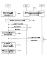
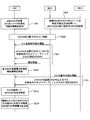
- FIG. 1 is a diagram illustrating an example of a timing chart when the terminal UE1 measures an adjacent cell for mobility control in the wireless communication system according to the first embodiment.
- a function capable of specifying a resource in which a specific DMRS broadcast by a cell is allocated is set in advance in the terminal UE1 (T101).
- the specific DMRS is a DMRS that performs precoding for all terminals or a DMRS that does not perform precoding.
- the radio communication device NE11 and the radio communication device NE12 illustrated in FIG. 1 arrange a specific DMRS so that the terminal UE1 can identify the resource where the specific DMRS is arranged (T103).
- the wireless communication device NE11 and the wireless communication device NE12 can share a table or a calculation formula for deriving a resource in which a specific DMRS is arranged from the cell ID with the wireless communication terminal UE1, in advance, from the cell ID of the own cell. Identify specific DMRS resources. By doing so, it is possible to avoid interference of specific DMRS between cells.
- the terminal UE1 is connected to a cell under the radio communication device NE11 (T105).
- the cell under radio communication apparatus NE11 broadcasts information (for example, a synchronization signal) that can identify the cell, specific DMRS, and broadcast information (T107).
- the terminal UE1 measures the received power of a cell (own cell) under the radio communication device NE11 and acquires broadcast information (T109).
- the cell under the radio communication device NE12 broadcasts information (for example, a synchronization signal) that can identify the cell and a specific DMRS (T111).
- information for example, a synchronization signal
- the terminal UE1 determines to perform cell reselection (Cell Reselection) to an adjacent cell based on the control information included in the broadcast information, the synchronization signal of the cell under the radio communication device NE12 To get.
- terminal UE1 specifies the resource by which specific DMRS is arrange
- terminal UE1 measures the received power of specific DMRS in the cell (adjacent cell) under radio
- the terminal UE1 When the terminal UE1 is in the connected state, the terminal UE1 acquires a measurement configuration (Measurement Configuration) included in the individual control information from the own cell. If the terminal UE1 determines that the measurement of the neighboring cell is necessary based on the measurement setting, the terminal UE1 acquires the synchronization signal of the cell under the radio communication device NE12. And terminal UE1 specifies the resource by which specific DMRS is arrange
- a measurement configuration Measurement Configuration
- the terminal UE1 can measure the received power of its own cell and neighboring cells by measuring a specific DMRS, whether in the idle state or in the connected state, and therefore performs mobility control. Can do.
- UE C1 in connected state is notified of CSI-RS resources from its own cell, it may perform measurement of its own cell by CSI-RS and may perform measurement of neighboring cells using a specific DMRS.
- the terminal UE1 may perform measurement using any one of CRS, CSI-RS, and specific DMRS depending on the cell type.
- the terminal UE1 measures the cell that broadcasts the CRS by CRS, and the cell that broadcasts the specific DMRS. Measure using specific DMRS.
- the UE UE1 may measure the neighboring cell using the CSI-RS and measure other cells using a specific DMRS. Good.
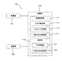
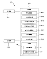
- FIG. 2 is a block diagram of the terminal UE1 configuring the wireless communication system according to the first embodiment.
- the terminal UE1 of the first embodiment includes a reception unit 101, a control unit 103, and a transmission unit 105.
- the control unit 103 includes a movement control unit 111, a cell ID detection unit 113, a cell type determination unit 115, a specific DMRS management unit 117, and a measurement unit 119.
- the measurement unit 119 includes a CRS measurement unit 121 and a specific DMRS measurement unit 123.
- the receiving unit 101 receives control information such as broadcast information or individual control information via the downlink of the cell to which the terminal UE1 is connected in response to an instruction from the control unit 103. In addition, the receiving unit 101 outputs the received control information to the control unit 103. In addition, the reception unit 101 measures CRS in response to an instruction from the CRS measurement unit 121 of the measurement unit 119 included in the control unit 103. The receiving unit 101 sends the CRS measurement result to the CRS measuring unit 121. In addition, the reception unit 101 measures DMRS in response to an instruction from the specific DMRS measurement unit 123 of the measurement unit 119 included in the control unit 103. The receiving unit 101 sends the DMRS measurement result to the specific DMRS measuring unit 123. The receiving unit 101 receives a synchronization signal in response to an instruction from the cell ID detection unit 113 of the control unit 103. The receiving unit 101 sends the received synchronization signal to the cell ID detection unit 113.
- the control unit 103 instructs the receiving unit 101 to receive control information such as broadcast information or individual control information. Control information received by the receiving unit 101 is input to the control unit 103. Information related to the measurement of the received power of the cell included in the control information input to the control unit 103 is input to the movement control unit 111 of the control unit 103. When the control unit 103 is instructed by the movement control unit 111 to measure an adjacent cell, the control unit 103 starts measuring the adjacent cell.
- control unit 103 each component included in the control unit 103 will be described.
- the mobility control unit 111 When the terminal UE1 is in an idle state, the mobility control unit 111 is adjacent based on the control information related to cell reselection (CellselectReselection) input from the control unit 103 and the reception power or reception quality of the own cell and adjacent cells. Determine whether to reselect to a cell. On the other hand, when the terminal UE1 is in the connected state, the mobility control unit 111 sends a measurement report (Measurement Report) based on the measurement settings input from the control unit 103 and the reception power or reception quality of the own cell and adjacent cells. create. The measurement report created by the movement control unit 111 is sent to the transmission unit 105.
- CellselectReselection cell reselection
- the movement control unit 111 instructs the CRS measurement unit 121 of the measurement unit 119 to measure the reception power or reception quality of the own cell.
- the movement control unit 111 instructs the specific DMRS measurement unit 123 of the measurement unit 119 to measure the reception power or reception quality of the own cell.
- the mobility control unit 111 determines that it is better to reselect the neighboring cell when the terminal UE1 is in the idle state, the mobility control unit 111 outputs the determination result to the control unit 103.
- the mobility control unit 111 determines to report the measurement report based on the measurement settings when the terminal UE1 is in the connected state, the mobility control unit 111 creates the measurement report and outputs the measurement report to the transmission unit 105.
- the mobility control unit 111 causes the cell ID detection unit 113 to Instructs cell detection.
- the cell ID detection unit 113 instructs the reception unit to receive a synchronization signal.
- the cell ID detection unit 113 detects the cell ID of the adjacent cell based on the synchronization signal input from the reception unit.
- the cell ID detection unit 113 outputs the detected cell ID to the cell type determination unit 115.
- the cell ID detection unit 113 acquires information (for example, a detection signal corresponding to the cell ID) necessary for detecting the cell ID of the adjacent cell from the control unit 103.
- the cell ID detection unit 113 may instruct the reception unit to detect the detection signal, and may detect an adjacent cell based on the detection signal received by the reception unit.
- the control unit 103 may include a method of knowing the detection signal corresponding to the cell ID from the broadcast information or the individual control information.
- the cell type determination unit 115 determines whether the cell type of the cell ID detected by the cell ID detection unit 113 is an “additional carrier type cell” or a conventional cell that reports PDCCH. When the cell type determination unit 115 determines that the cell type of the cell ID is “additional carrier type cell”, the cell type determination unit 115 outputs the cell ID to the specific DMRS management unit 117. On the other hand, when the cell type determination unit 115 determines that the cell type of the cell ID is a conventional cell, the cell type determination unit 115 outputs the cell ID to the CRS measurement unit 121 of the measurement unit 119.
- the cell type determination unit 115 determines the cell type by executing one of the following determination method examples.
- the cell type determination unit 115 determines whether the cell is an “additional carrier type cell” or a conventional cell from the frequency. By doing in this way, since the terminal can perform a cell search after specifying that it is an “additional carrier type cell”, the power consumption of the terminal can be suppressed.
- the synchronization signal of the additional carrier type cell is different from the synchronization signal of the conventional cell. That is, the additional carrier type cell uses a sequence obtained by inverting a PSS (Primary Synchronization Signal) sequence in subframe number 0 and subframe number 5. Therefore, in the case of an additional carrier type cell, the PSS of subframe number 0 and the PSS of subframe number 5 are added to zero, and subtracted to double the size. On the other hand, in the case of a conventional cell, the PSS of subframe number 0 and the PSS of subframe number 5 are added to double the size, and subtracted to zero.
- the cell type determination unit 115 determines whether the cell is an “additional carrier type cell” or a conventional cell based on the calculation results obtained by adding and subtracting the PSS of subframe number 0 and the PSS of subframe number 5.
- an additional carrier type cell synchronization signal is placed in a resource at a position different from that of a conventional cell synchronization signal.
- the cell type determination unit 115 attempts to detect synchronization signals of both the additional carrier type cell and the conventional cell. When the synchronization signal can be detected, the cell type determination unit 115 determines whether the cell is an additional carrier type cell or a conventional cell according to the position of the detected synchronization signal.
- the cell type determination unit 115 determines whether the cell is an additional carrier type cell or a conventional cell based on a CRC (Cyclic Redundancy Check) of a MIB (Master Information Block).
- the additional carrier type cell is set so that resources used for MIB notification differ at the RE level.
- CRC Cyclic Redundancy Check
- MIB Master Information Block
- ⁇ Fifth determination method example> information indicating whether or not the cell is an additional carrier type cell is included in the broadcast information.
- the cell type determination unit 115 determines whether or not the cell is an additional carrier type cell based on information included in the broadcast information. Note that the information included in the broadcast information may be a flag indicating that it is an additional carrier type cell.
- the cell type determination unit 115 may determine which is notified by the network according to the situation. In this case, a method in which the network notifies by Choice may be used. The cell type determination unit 115 compares the cell ID detected by the cell ID detection unit 113 from the synchronization signal and the adjacent cell list to determine whether the cell is an additional carrier type cell.
- the cell type determination unit 115 may determine the cell type by a method other than the above.
- the CRS measurement unit 121 of the measurement unit 119 When the cell ID is input, the CRS measurement unit 121 of the measurement unit 119 notifies the reception unit 101 of the CRS resource corresponding to the preset cell ID, and instructs the reception unit 101 to measure the CRS. To do.
- the CRS measurement unit 121 calculates reception power or reception quality based on the CRS measurement result input from the reception unit 101, and outputs the calculation result to the movement control unit 111.
- the specific DMRS management unit 117 when the cell ID is input, specifies a resource in which a specific DMRS that can be used for mobility control is arranged.
- the specific DMRS is a DMRS that performs precoding for all terminals or a DMRS that does not perform precoding.
- the specific DMRS management unit 117 outputs the resource and cell ID in which the specific DMRS is arranged to the specific DMRS measurement unit 123 of the measurement unit 119.
- the specific DMRS management unit 117 specifies a specific DMRS resource by executing one of the following specific method examples.
- the specific DMRS management unit 117 holds a table or calculation formula for deriving a resource in which a specific DMRS is arranged from the cell ID.
- the specific DMRS management unit 117 specifies a specific DMRS resource corresponding to the input cell ID based on the table or the calculation formula. In this way, if a cell ID is detected, a specific DMRS can be specified. That is, since the arrangement of a specific DMRS can be changed between cells, interference control can be performed.
- the same resource is used between cells as a specific DMRS resource.
- the specific DMRS management unit 117 specifies a specific DMRS resource that is common among cells held in advance. By doing in this way, terminal UE1 does not need to hold
- the broadcast information of the own cell includes the specific DMRS resource of the own cell and the specific DMRS resource of the neighboring cell.
- the specific DMRS management unit 117 specifies a specific DMRS resource corresponding to the input cell ID by receiving broadcast information of the own cell.
- the terminal UE1 When the terminal UE1 is in a connected state with the own cell, the terminal UE1 is notified of information regarding a resource in which a specific DMRS is arranged in an adjacent cell by the dedicated control information sent from the own cell.
- the specific DMRS management unit 117 specifies a specific DMRS resource corresponding to the input cell ID by receiving the individual control information of the own cell.
- the specific DMRS management unit 117 holds a table or calculation formula for deriving a resource of a specific DMRS.
- the specific DMRS management unit 117 derives a list of resources in which a specific DMRS may exist from a table or a calculation formula.
- the specific DMRS management unit 117 specifies a resource of a specific DMRS by blind-decoding a list of resources in which the specific DMRS may exist. In this way, it is possible to arrange a specific DMRS with a certain degree of freedom.
- the specific DMRS management unit 117 may specify a specific DMRS resource using a method other than the above.
- the specific DMRS measurement unit 123 of the measurement unit 119 When the cell ID and the specific DMRS resource are input, the specific DMRS measurement unit 123 of the measurement unit 119 notifies the reception unit 101 of these and instructs the reception unit 101 to measure the DMRS.
- the specific DMRS measurement unit 123 calculates reception power or reception quality based on the DMRS measurement result input from the reception unit 101, and outputs the calculation result to the movement control unit 111.
- the transmission unit 105 transmits a random access preamble, a control signal response, data, or the like. Further, the transmission unit 105 transmits a UL packet to the wireless communication device NE11 or NE12 at a transmission timing corresponding to the wireless communication device.
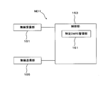
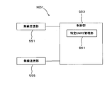
- FIG. 3 is a block diagram of the wireless communication device NE11 that constitutes the wireless communication system of the first embodiment.
- the wireless communication device NE11 according to the first embodiment includes a wireless reception unit 151, a control unit 153, and a wireless transmission unit 155.
- the control unit 153 includes a specific DMRS management unit 161.
- the radio reception unit 151 receives a random access preamble or a control signal response transmitted from the terminal UE1, and outputs the received random access preamble to the control unit 153. In addition, the radio reception unit 151 receives the UL packet transmitted from the terminal UE1 and outputs the UL packet to the control unit 153.
- the control unit 153 determines a specific DMRS resource using a method that can be detected by the terminal UE1, and relates to the determined resource The information is output to the specific DMRS management unit 161. In addition, the control unit 153 sends an instruction to perform precoding for all terminals to a specific DMRS or an instruction not to perform precoding to a specific DMRS to the specific DMRS management unit 161. The control unit 153 generates notification information and outputs it to the wireless transmission unit 155.
- control unit 153 When a specific DMRS is used, the control unit 153 performs precoding for all terminals on a packet corresponding to the specific DMRS, or performs wireless transmission without performing precoding on a packet corresponding to the specific DMRS. Output to the unit 155.
- the control unit 153 generates a random access response corresponding to the random access preamble and outputs it to the wireless transmission unit 155.
- the control unit 153 generates individual control information for each terminal and outputs it to the wireless transmission unit 155.
- the specific DMRS management unit 161 outputs the specific DMRS to the radio transmission unit 155 in accordance with an instruction from the control unit 153, with or without performing precoding for all terminals on the specific DMRS.
- the wireless transmission unit 155 transmits the specific DMRS input from the specific DMRS management unit 161 to the terminal UE1.
- the radio transmission unit 155 transmits data, broadcast information, individual control information, a random access response, or the like input from the control unit 153 to the terminal UE1.
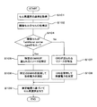
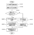
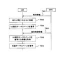
- FIG. 4 is a flowchart when the idle terminal UE1 performs cell reselection in the radio communication system according to the first embodiment. Note that the terminal UE1 is connected to a cell (own cell) provided by the wireless communication device NE11 and is in an idle state.
- the terminal UE1 obtains a cell reselection reference or the like based on broadcast information from the own cell (step S101).
- the terminal UE1 detects the cell ID of the adjacent cell (step S102).
- the terminal UE1 determines whether or not the adjacent cell is an “additional carrier type cell” (step S104).
- the terminal UE1 tries both the cell ID detection method for additional carrier type and the conventional cell ID detection method in step S102 by blind decoding.
- the terminal UE1 determines whether the cell is an additionaladdcarrier type cell according to which method the cell ID is detected. Further, the terminal UE1 may try to detect the cell ID of the cell after determining that the cell is of the additional carrier type.
- step S104 If it is determined in step S104 that the cell is an additional carrier type cell (that is, if Yes), the process proceeds to step S105, and if it is determined that the cell is not an additional carrier type cell (that is, if it is No). Proceed to step S107.
- step S105 the terminal UE1 specifies a resource to which a specific DMRS for which precoding for all terminals is performed or precoding is not performed is transmitted.
- terminal UE1 measures received power using a specific DMRS (step S106).
- step S107 terminal UE1 specifies the resource to which CRS is sent from the cell ID.
- the terminal UE1 measures received power using the CRS transmitted using the resource of the specified cell ID (step S108).
- step S106 If the terminal UE1 succeeds in measuring the received power in step S106 or S108, the process proceeds to step S109.
- step S109 the terminal UE1 performs cell reselection based on the measurement result of the received power.
- the connected terminal UE1 may perform movement control using a method similar to the above. That is, in step S109, the terminal UE1 creates a measurement result report based on the reception power measurement result.
- the terminal UE1 can acquire received power by measuring a specific DMRS, it can move without using a CRS used as a reference signal in LTE. Control is possible. Further, the idle terminal UE1 can perform cell reselection in the same procedure as conventional cell reselection by using a specific DMRS. For this reason, while being able to reduce the processing load of terminal UE1, it is not necessary to add a new reference signal. Also, resource allocation in the cell is easy.
- the wireless communication system according to the second embodiment is different from the wireless communication system according to the first embodiment in that DMRS (precoding for all terminals measured by the terminal for mobility control is performed or precoding is not performed. Specific DMRS) is limited to DMRS on the RB where the ePDCCH is sent. Except for this point, the second embodiment is the same as the first embodiment.
- DMRS precoding for all terminals measured by the terminal for mobility control is performed or precoding is not performed.
- Specific DMRS is limited to DMRS on the RB where the ePDCCH is sent. Except for this point, the second embodiment is the same as the first embodiment.
- FIG. 5 is a diagram illustrating an example of a timing chart when the terminal UE2 measures an adjacent cell for mobility control in the wireless communication system according to the second embodiment.
- a function capable of identifying a resource in which an ePDCCH transmitted by a cell is allocated is set in advance in the terminal UE2 (T201).
- the radio communication device NE21 and the radio communication device NE22 illustrated in FIG. 5 arrange a specific DMRS in the RB of the ePDCCH so that the terminal UE2 can specify the ePDCCH resource (T203).
- the radio communication device NE21 and the radio communication device NE22 share in advance a table or a calculation formula for deriving a resource where the ePDCCH is allocated from the cell ID with the radio communication terminal UE2, so that the ePDCCH can be calculated from the cell ID of the own cell. Identify resources. By doing so, it is possible to avoid interference of ePDCCH between cells.
- the terminal UE2 is connected to a cell under the radio communication device NE21 (T205).
- a cell under the radio communication device NE21 has information for identifying the cell (for example, a synchronization signal), a specific DMRS that is precoded or not precoded for all terminals transmitted on an RB that transmits ePDCCH And broadcast information is notified (T207).
- the terminal UE2 measures received power of a cell (own cell) under the radio communication device NE21 and acquires broadcast information (T209).
- the cell under the radio communication device NE22 broadcasts information that can identify the cell (for example, a synchronization signal) and a specific DMRS that is precoded or not precoded for all terminals on the RB that transmits the ePDCCH (T211).
- the terminal UE2 acquires a synchronization signal of a cell under the radio communication device NE22 when determining that the cell reselection to the adjacent cell is performed based on the control information included in the broadcast information.
- terminal UE2 specifies RB of ePDCCH, after identifying a cell from the acquired synchronous signal (T213).
- terminal UE2 measures the reception power of specific DMRS on RB in which ePDCCH is transmitted in the cell (adjacent cell) under radio communication apparatus NE12 (T215).
- the terminal UE2 When the terminal UE2 is in the connected state, the terminal UE2 acquires a measurement configuration (Measurement Configuration) included in the individual control information from the own cell. If the terminal UE2 determines that the measurement of the adjacent cell is necessary based on the measurement setting, the terminal UE2 acquires the synchronization signal of the cell under the radio communication device NE22. And terminal UE2 specifies RB by which ePDCCH is arrange
- a measurement configuration Measurement Configuration
- the terminal UE2 measures a specific DMRS that is precoded or not precoded for all terminals on the RB to which the ePDCCH is sent, whether in an idle state or a connected state.
- the mobility control can be performed.
- the terminal UE2 can use the specific DMRS for decoding the common search space (Common Search Space) of the ePDCCH. For this reason, it is possible to reduce the influence of a decrease in transmission efficiency caused by sending a specific DMRS.
- Common Search Space Common Search Space
- the radio communication device NE21 and the radio communication device NE22 may limit RBs for transmitting a specific DMRS to some RBs among RBs to which ePDCCH is sent. In this way, ePDCCH can be allocated to a resource different from the resource obtained by the above method. Furthermore, since ePDCCH for which precoding for all terminals is performed or precoding is not performed can be reduced, ePDCCH resources can be effectively used.
- RBs that transmit a specific DMRS may be limited to ePDCCH RBs to which a common search space (Common Search Space) may be sent.
- a specific DMRS can be used for decoding the ePDCCH common search space (Common Search Space), so the specific DMRS can be used for mobility control and decoding purposes.
- the radio resources can be used efficiently.
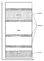
- FIG. 6 is a diagram illustrating an example of a subframe in which “Localized ePDCCH” and “Distributed ePDCCH” are mixed.
- the wireless communication device NE21 and the wireless communication device NE22 may change the ePDCCH for transmitting a specific DMRS to “Distributed ePDCCH”. By doing so, it is possible to perform measurement while suppressing the influence of frequency fading when measuring the received power of a specific DMRS, so that the measurement accuracy can be increased.
- the radio communication device NE21 and the radio communication device NE22 may change the RB for sending a specific DMRS between subframes. That is, by changing the arrangement of RBs including both ePDCCH and specific DMRS for each subframe, it is possible to measure received power while suppressing the influence of frequency fading.
- the terminal UE2 specifies ePDCCH resources for each subframe and measures the received power of a specific DMRS for mobility control. In addition, you may change for every slot instead of every sub-frame, and you may change for every several sub-frames.
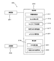
- FIG. 7 is a block diagram of the terminal UE2 constituting the wireless communication system of the second embodiment.
- the terminal UE2 of the second embodiment includes a reception unit 201, a control unit 203, and a transmission unit 205.
- the control unit 203 includes a movement control unit 211, a cell ID detection unit 213, a cell type determination unit 215, a specific DMRS management unit 217, an ePDCCH management unit 231 and a measurement unit 219.
- the measurement unit 219 includes a CRS measurement unit 221 and a specific DMRS measurement unit 223.
- the reception unit 201 receives control information such as broadcast information or individual control information via the downlink of the cell to which the terminal UE2 is connected. In addition, the receiving unit 201 outputs the received control information to the control unit 203.
- the receiving unit 201 measures CRS in response to an instruction from the CRS measuring unit 221 of the measuring unit 219 included in the control unit 203.
- the receiving unit 201 sends the CRS measurement result to the CRS measuring unit 221.
- the reception unit 201 measures DMRS in response to an instruction from the specific DMRS measurement unit 223 of the measurement unit 219 included in the control unit 203.
- the receiving unit 201 sends the DMRS measurement result to the specific DMRS measuring unit 223.
- the receiving unit 201 receives a synchronization signal in response to an instruction from the cell ID detection unit 213 of the control unit 203.
- the reception unit 201 sends the received synchronization signal to the cell ID detection unit 213.
- the control unit 203 instructs the reception unit 201 to receive control information such as broadcast information or individual control information.
- Control information received by the receiving unit 201 is input to the control unit 203.
- Information related to the measurement of the received power of the cell included in the control information input to the control unit 203 is input to the movement control unit 211 of the control unit 203.
- the control unit 203 starts measuring the adjacent cell.
- control unit 203 each component included in the control unit 203 will be described.
- the movement control unit 211 When the terminal UE1 is in an idle state, the movement control unit 211 performs re-transmission to the adjacent cell based on the control information regarding cell reselection input from the control unit 203 and the reception power or reception quality of the own cell and the adjacent cell. Determine whether to make a selection. On the other hand, when the terminal UE2 is in a connected state, the mobility control unit 211 performs a measurement report (Measurement Report) based on the measurement settings input from the control unit 203 and the received power or reception quality of the own cell and the neighboring cell. create. The measurement report created by the movement control unit 211 is sent to the transmission unit 205.
- a measurement report Measurement Report
- the mobility control unit 211 instructs the CRS measurement unit 221 of the measurement unit 219 to measure the reception power or reception quality of the own cell.
- the movement control unit 211 instructs the specific DMRS measurement unit 223 of the measurement unit 219 to measure the reception power or reception quality of the own cell.
- the movement control unit 211 determines that it is better to reselect an adjacent cell when the terminal UE2 is in an idle state, the movement control unit 211 outputs the determination result to the control unit 203.
- the mobility control unit 211 creates the measurement report and outputs the measurement report to the transmission unit 205.
- the mobile control unit 211 determines that the measurement of the neighboring cell is started based on the reception power or reception quality of the own cell input from the measurement unit 219 when the terminal UE2 is in the connected state, the mobile control unit 211 causes the cell ID detection unit 213 to Instructs cell detection.
- the cell ID detection unit 213 instructs the reception unit to receive a synchronization signal.
- the cell ID detection unit 213 detects the cell ID of the adjacent cell based on the synchronization signal input from the reception unit.
- the cell ID detection unit 213 outputs the detected cell ID to the cell type determination unit 215.
- the cell ID detection unit 213 acquires information (for example, a detection signal corresponding to the cell ID) necessary for detecting the cell ID of the adjacent cell from the control unit 203.
- the cell ID detection unit 213 may instruct the reception unit to detect the detection signal, and may detect an adjacent cell based on the detection signal received by the reception unit.
- the control unit 203 may include a method of knowing the detection signal corresponding to the cell ID from the broadcast information or the individual control information.
- the cell type determination unit 215 determines whether the cell type of the cell ID detected by the cell ID detection unit 213 is “additional carrier type cell” or a conventional cell that broadcasts PDCCH. When the cell type determination unit 215 determines that the cell type of the cell ID is “additional carrier type cell”, the cell type determination unit 215 outputs the cell ID to the ePDCCH management unit 231. On the other hand, when the cell type determination unit 215 determines that the cell type of the cell ID is a conventional cell, the cell type determination unit 215 outputs the cell ID to the CRS measurement unit 221 of the measurement unit 219. When the ePDCCH resource is input from the ePDCCH management unit 231, the cell type determination unit 215 outputs the cell ID and the ePDCCH resource to the specific DMRS management unit 217.
- the cell type determination unit 215 determines the cell type by executing one of the following determination method examples.
- the cell type determination unit 215 determines whether the cell is an “additional carrier type cell” or a conventional cell from the frequency.
- the synchronization signal of the additional carrier type cell is different from the synchronization signal of the conventional cell. That is, the additional carrier type cell uses a sequence obtained by inverting a PSS (Primary Synchronization Signal) sequence in subframe number 0 and subframe number 5. Therefore, in the case of an additional carrier type cell, the PSS of subframe number 0 and the PSS of subframe number 5 are added to zero, and subtracted to double the size. On the other hand, in the case of a conventional cell, the PSS of subframe number 0 and the PSS of subframe number 5 are added to double the size, and subtracted to zero.
- the cell type determination unit 215 determines whether the cell is an “additional carrier type cell” or a conventional cell based on calculation results obtained by adding and subtracting the PSS of subframe number 0 and the PSS of subframe number 5.
- an additional carrier type cell synchronization signal is placed in a resource at a position different from that of a conventional cell synchronization signal.
- the cell type determination unit 215 attempts to detect synchronization signals of both the additional carrier type cell and the conventional cell. When the synchronization signal can be detected, the cell type determination unit 215 determines whether the cell is an additional carrier type cell or a conventional cell according to the position of the detected synchronization signal.
- the cell type determination unit 215 determines whether the cell is an additional carrier type cell or a conventional cell based on a CRC (Cyclic Redundancy Check) of a MIB (Master Information Block).
- the additional carrier type cell is set so that resources used for MIB notification differ at the RE level.
- CRC Cyclic Redundancy Check
- MIB Master Information Block
- ⁇ Fifth determination method example> information indicating whether or not the cell is an additional carrier type cell is included in the broadcast information.
- the cell type determination unit 215 determines whether the cell is an additional carrier type cell based on information included in the broadcast information. Note that the information included in the broadcast information may be a flag indicating that it is an additional carrier type cell.
- the adjacent cell is an additional carrier type cell
- the information may be a flag indicating whether or not all adjacent cells are additional carrier type cells.
- the information may be a neighbor cell list indicating whether or not each cell is an additional carrier type cell for each neighbor cell identifier.
- the cell type determination unit 215 may determine which is notified by the network according to the situation. In this case, a method in which the network notifies by Choice may be used.
- the cell type determination unit 215 compares the cell ID detected from the synchronization signal by the cell ID detection unit 213 with the adjacent cell list to determine whether the cell is an additional carrier type cell.
- the cell type determination unit 215 may determine the cell type by a method other than the above.
- the CRS measurement unit 221 of the measurement unit 219 When the cell ID is input, the CRS measurement unit 221 of the measurement unit 219 notifies the reception unit 201 of the CRS resource corresponding to the preset cell ID and instructs the reception unit 201 to measure the CRS. To do.
- the CRS measurement unit 221 calculates reception power or reception quality based on the CRS measurement result input from the reception unit 201, and outputs the calculation result to the movement control unit 211.
- the ePDCCH management unit 231 When the cell ID is input, the ePDCCH management unit 231 derives ePDCCH resources corresponding to the cell ID. Note that the ePDCCH management unit 231 outputs only the ePDCCH resource on the RB including the specific DMRS to the cell type determination unit 215.
- the ePDCCH resource may be any value that allows the specific DMRS management unit 217 to specify the resource in which the specific DMRS is arranged. For example, an RB number may be used.
- the ePDCCH management unit 231 identifies ePDCCH resources by executing one of the following derivation methods.
- the ePDCCH management unit 231 holds a table or calculation formula for deriving ePDCCH resources from the cell ID.
- the ePDCCH management unit 231 identifies the ePDCCH resource corresponding to the input cell ID based on the table or the calculation formula.
- ⁇ Second example of derivation method> the same resource is used between cells as an ePDCCH resource.
- the ePDCCH management unit 231 specifies a common ePDCCH resource among cells held in advance.
- the broadcast information of the own cell includes the ePDCCH resource of the own cell and the ePDCCH resource of the neighboring cell.
- the ePDCCH management unit 231 specifies the ePDCCH resource for the input cell ID by receiving the broadcast information of the own cell.
- the terminal UE2 When the terminal UE2 is connected to the own cell, the terminal UE2 is notified of information related to the ePDCCH resource of the adjacent cell by the dedicated control information transmitted from the own cell.
- the ePDCCH management unit 231 specifies the ePDCCH resource corresponding to the input cell ID by receiving the individual control information of the own cell.
- the ePDCCH management unit 231 holds a table or calculation formula for deriving ePDCCH resources.
- the ePDCCH management unit 231 derives a list of resources that may have the ePDCCH from a table or a calculation formula.
- the specific DMRS management unit 217 specifies ePDCCH resources by blind-decoding a list of resources that may have ePDCCHs. By doing so, it is possible to arrange ePDCCH with a degree of freedom.
- the ePDCCH management unit 231 may specify ePDCCH resources using a method other than the above.
- the specific DMRS management unit 217 specifies the DMRS on the RB transmitted using the ePDCCH resource as the specific DMRS.
- the specific DMRS management unit 217 outputs the resource in which the specific DMRS is arranged and the cell ID to the specific DMRS measurement unit 223 of the measurement unit 219.
- the specific DMRS measurement unit 223 of the measurement unit 219 When the cell ID and the specific DMRS resource are input, the specific DMRS measurement unit 223 of the measurement unit 219 notifies the reception unit 201 of them and instructs the reception unit 201 to measure the DMRS.
- the specific DMRS measurement unit 223 calculates reception power or reception quality based on the DMRS measurement result input from the reception unit 201, and outputs the calculation result to the movement control unit 211.
- the transmission unit 205 transmits a random access preamble, a control signal response, data, or the like. Further, the transmission unit 205 transmits a UL packet to the wireless communication device NE21 or NE22 at a transmission timing corresponding to the wireless communication device.
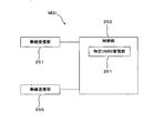
- FIG. 8 is a block diagram of the wireless communication device NE21 constituting the wireless communication system of the second embodiment.
- the wireless communication device NE21 according to the second embodiment includes a wireless reception unit 251, a control unit 253, and a wireless transmission unit 255.
- the control unit 253 includes a specific DMRS management unit 261.
- the radio reception unit 251 receives a random access preamble or a control signal response transmitted from the terminal UE2, and outputs the received random access preamble to the control unit 253. In addition, the radio reception unit 251 receives the UL packet transmitted from the terminal UE2 and outputs the UL packet to the control unit 253.
- the control unit 253 determines a resource of ePDCCH transmitted by an RB including a specific DMRS using a method that can be detected by the terminal UE2. Then, the information regarding the determined resource is output to the specific DMRS management unit 261. In addition, the control unit 253 performs precoding for all terminals with respect to the specific DMRS, or sends an instruction not to perform precoding to the specific DMRS to the specific DMRS management unit 261. The control unit 253 generates notification information and outputs it to the wireless transmission unit 255.
- the control unit 253 When a specific DMRS is used, the control unit 253 performs precoding for all terminals on a packet corresponding to the specific DMRS, or performs wireless transmission without performing precoding on a packet corresponding to the specific DMRS. Output to the unit 255.
- the control unit 253 generates a random access response corresponding to the random access preamble and outputs the random access response to the wireless transmission unit 255.
- the control unit 253 generates individual control information for each terminal and outputs the individual control information to the wireless transmission unit 255.
- the specific DMRS management unit 261 uses the DMRS of the RB to which the ePDCCH resource input from the control unit 253 is transmitted as the specific DMRS. Also, the specific DMRS management unit 261 outputs the specific DMRS to the radio transmission unit 255 according to an instruction from the control unit 253, with or without performing precoding for all terminals on the specific DMRS. To do.
- the radio transmission unit 255 transmits the specific DMRS input from the specific DMRS management unit 261 to the terminal UE2.
- the radio transmission unit 255 transmits data, broadcast information, individual control information, a random access response, or the like input from the control unit 253 to the terminal UE2.
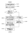
- FIG. 9 is a flowchart when the idle UE UE2 performs cell reselection in the wireless communication system according to the second embodiment.
- the terminal UE2 is connected to a cell (own cell) provided by the wireless communication device NE21 and is in an idle state.
- the terminal UE2 obtains a cell reselection reference or the like based on broadcast information from the own cell (step S101).
- the terminal UE2 detects the cell ID of the adjacent cell (step S102).
- the terminal UE2 determines whether or not the adjacent cell is an “additional carrier type cell” (step S104).
- the terminal UE2 tries both the cell ID detection method for additional carrier type and the conventional cell ID detection method in step S102 by blind decoding.
- the terminal UE2 determines whether or not the cell is an additional carrier type cell depending on which method the cell ID is detected.
- the terminal UE2 may attempt to detect the cell ID of the cell after determining that the cell is an additional carrier type cell.
- step S104 determines whether the cell is an additional carrier type cell (that is, if Yes). If it is determined in step S104 that the cell is an additional carrier type cell (that is, if Yes), the process proceeds to step S205, and if it is determined that the cell is not an additional carrier type cell (that is, if it is No). Proceed to step S107.
- step S205 the terminal UE2 identifies the RB to which ePDCCH is sent. Next, the terminal UE2 measures received power using a specific DMRS included in the RB to which ePDCCH is sent (step S206). On the other hand, in step S107, the terminal UE2 identifies the resource to which the CRS is transmitted from the cell ID. Next, the terminal UE2 measures received power using the CRS transmitted using the resource of the identified cell ID (step S108).
- step S109 the terminal UE2 performs cell reselection based on the measurement result of the received power.
- Distributed ePDCCH may also be used.
- the terminal UE2 can measure the received power of the adjacent cell and perform cell reselection to a better cell for both the terminal UE2 and the radio communication apparatuses NE21 and NE22.
- the wireless communication devices NE21 and NE22 can transmit data with directivity by performing precoding for all terminals or not performing precoding only for a specific DMRS on the RB to which ePDCCH is transmitted. Therefore, transmission characteristics in the data area can be maintained.
- the terminal UE2 in the connected state may perform mobility control using the same method as described above. That is, in step S109, the terminal UE2 creates a measurement result report based on the reception power measurement result.
- the terminal UE2 can acquire the received power by measuring a specific DMRS on the RB to which the ePDCCH is transmitted, and thus is used as a reference signal in LTE. Movement control is possible without using CRS. Also, idle UE UE2 can perform cell reselection in the same procedure as conventional cell reselection by using a specific DMRS on the RB to which ePDCCH is sent. For this reason, while being able to reduce the processing load of terminal UE2, it is not necessary to add a new reference signal. Also, resource allocation in the cell is easy.
- a wireless communication system according to the third embodiment will be described.
- the wireless communication system according to the third embodiment is different from the wireless communication system according to the second embodiment in that precoding for all terminals measured by the terminal for mobility control is performed or no precoding is performed. Limiting DMRS to DMRS on RB to which ePDCCH of a specific subframe is sent. Except for this point, the second embodiment is the same as the second embodiment, and a description of the configuration of the terminal and the wireless communication device that configure the wireless communication system of the present embodiment will be omitted.
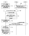
- FIG. 10 is a flowchart when the idle terminal UE3 performs cell reselection in the wireless communication system according to the third embodiment.
- the same reference numerals are assigned to the same processing steps as those shown in FIG. 9 in the second embodiment.
- the terminal UE3 is connected to a cell (own cell) provided by the wireless communication device NE3 and is in an idle state.
- the terminal UE3 obtains a cell reselection criterion or the like based on broadcast information from the own cell (step S101). Next, the terminal UE3 detects the cell ID of the neighboring cell (step S102). Next, the terminal UE3 determines whether or not the adjacent cell is “additional carrier type cell” (step S104). At this time, for example, the terminal UE3 tries both the cell ID detection method for additional carrier type and the conventional cell ID detection method in step S102 by blind decoding. The terminal UE3 determines whether the cell is an additionaladdcarrier type cell depending on which method is used to detect the cell ID. In addition, the terminal UE3 may try to detect the cell ID of the cell after determining that the cell is an additional carrier type cell.
- step S104 determines whether the cell is an additional carrier type cell (that is, if Yes). If it is determined in step S104 that the cell is an additional carrier type cell (that is, if Yes), the process proceeds to step S305, and if it is determined that the cell is not an additional carrier type cell (that is, if it is No). Proceed to step S107.
- step S305 the terminal UE3 specifies a subframe to be measured for mobility control, and further specifies an RB to which ePDCCH is transmitted in the specified subframe. Next, the terminal UE3 measures received power using a specific DMRS included in the RB to which ePDCCH is transmitted in the subframe (step S306).
- step S107 terminal UE3 specifies the resource to which CRS is sent from the cell ID. Next, the terminal UE3 measures received power using the CRS transmitted using the resource of the specified cell ID (step S108).
- step S109 the terminal UE3 performs cell reselection based on the measurement result of the received power.
- a specific DMRS on an RB to which ePDCCH is transmitted is transmitted with directivity in some subframes. be able to. Since ePDCCH can be sent with directivity in this way, ePDCCH resources can be used efficiently. As a result, the probability that a control signal cannot be transmitted in ePDCCH can be reduced.
- the terminal UE3 in the connected state may perform movement control using the same method as described above. That is, in step S109, the terminal UE3 creates a measurement result report based on the reception power measurement result.
- the DMRS on the RB to which the ePDCCH is transmitted in the specific subframe has been described as the specific DMRS.
- the DMRS included in the specific RB in the specific subframe may be the specific DMRS. . This is because by limiting the subframes, the amount of data transmitted without directivity can be suppressed even if DMRS without directivity is transmitted using the data area. And while limiting a sub-frame, since the number of reference signals which can be measured within a sub-frame increases, a measurement precision can be improved.
- the DMRS on the RB to which ePDCCH is transmitted in a specific subframe has been described as the specific DMRS. However, as in the second embodiment, the ePDCCH is transmitted to the RB including the specific DMRS. You may limit to some RB in RB.
- the specific subframe may be limited to a subframe with a high probability that a common search space is used on ePDCCH, such as SIB1, random access response (Random Access Response), or paging.
- a common search space such as SIB1, random access response (Random Access Response), or paging.
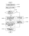
- a wireless communication system according to the fourth embodiment will be described with reference to FIGS.
- the wireless communication system of the fourth embodiment is different from the wireless communication system of the second embodiment in that a specific DMRS is limited to a DMRS of a specific antenna port. Except for this point, the second embodiment is the same as the second embodiment.
- FIG. 11 is a diagram illustrating an example of a timing chart when the terminal UE4 measures an adjacent cell for mobility control in the wireless communication system according to the fourth embodiment.
- the terminal UE4 is configured in advance with a function capable of acquiring information on resources in which ePDCCH transmitted by a cell is arranged and an antenna port to which a specific DMRS is transmitted (T401).
- T401 a function capable of acquiring information on resources in which ePDCCH transmitted by a cell is arranged and an antenna port to which a specific DMRS is transmitted
- T401 an antenna port to which a specific DMRS is transmitted
- the same method as that of the second embodiment can be applied to the method for identifying the resource where the ePDCCH is arranged.
- the same method as in the first embodiment can be applied to the cell type determination method.
- the radio communication device NE41 and the radio communication device NE42 illustrated in FIG. 11 arrange the ePDCCH so that the terminal UE4 can identify the ePDCCH resource,
- the terminal UE4 is connected to a cell under the radio communication device NE41 (T405).
- the cell under the radio communication device NE41 broadcasts information that can identify the cell (for example, a synchronization signal), a specific DMRS transmitted using a specific antenna port on the RB that transmits the ePDCCH, and broadcast information ( T407).
- the terminal UE4 measures the received power of the cell (own cell) under the radio communication device NE41 and acquires broadcast information (T409).
- the cell under the radio communication device NE42 broadcasts information (for example, a synchronization signal) that can identify the cell and a specific DMRS transmitted using a specific antenna port on the RB that transmits the ePDCCH (T411).
- information for example, a synchronization signal
- the terminal UE4 is in the idle state, if it is determined that the cell reselection to the adjacent cell is performed based on the control information included in the broadcast information, the synchronization signal of the cell under the radio communication device NE42 is acquired. Then, after identifying the cell from the acquired synchronization signal, the terminal UE4 specifies a specific antenna port to which the RB of the ePDCCH and a specific DMRS are transmitted (T413). And terminal UE4 measures the received power of the specific DMRS transmitted by a specific antenna port in RB where ePDCCH is transmitted in the cell (adjacent cell) under radio communication apparatus NE42 (T415).
- the terminal UE4 When the terminal UE4 is in the connected state, the terminal UE4 acquires a measurement configuration (Measurement Configuration) included in the individual control information from the own cell. If the terminal UE4 determines that the measurement of the neighboring cell is necessary based on the measurement setting, the terminal UE4 acquires the synchronization signal of the cell under the radio communication device NE42. Then, after identifying the cell from the acquired synchronization signal, the terminal UE4 specifies a specific antenna port to which the RB in which the ePDCCH is arranged and a specific DMRS are transmitted. And terminal UE4 measures the received power of the specific DMRS transmitted by a specific antenna port in RB where ePDCCH is transmitted in a cell (adjacent cell) under radio communication apparatus NE42.
- a measurement configuration Measurement Configuration
- the terminal UE4 receives the own cell and the neighboring cell by measuring a specific DMRS transmitted at a specific antenna port in the RB to which the ePDCCH is transmitted, whether in the idle state or the connected state. Since electric power can be measured, movement control can be performed.
- terminal UE4 uses DMRS sent by a specific antenna port in an RB to which ePDCCH is sent as a specific DMRS, terminal UE4 uses DMRS sent by a specific antenna port as a common search space (Common Search Space) of ePDCCH. Can be used for decryption. For this reason, it is possible to reduce the influence of a decrease in transmission efficiency caused by sending a specific DMRS.
- Common Search Space Common Search Space
- the terminal UE4 may also perform decoding of the UE individual search space (UE specific Search Space) using the same specific DMRS. In that case, since it is not necessary to send DMRS in other antenna ports, the resource can be utilized for sending ePDCCH and data.
- UE specific Search Space UE specific Search Space
- the terminal UE4 when a specific DMRS is transmitted using SFBC (Space Frequency Block Code), the terminal UE4 also performs decoding of ePDCCH using SFBC. In addition, when a specific DMRS is sent in the same RB as the data, if the DMRS used for decoding the data is a specific DMRS sent using SFBC, the terminal UE4 decodes the data using SFBC. Do. In this way, ePDCCH or data can be decoded.
- SFBC Space Frequency Block Code
- the radio communication device NE41 and the radio communication device NE42 may limit RBs for transmitting a specific DMRS to some RBs to which ePDCCH is sent. By doing so, the ePDCCH can be arranged in a resource different from the resource required by the above method, as in the above method. Furthermore, since ePDCCH can be reduced by performing precoding for all terminals or not by precoding, the resources of ePDCCH can be effectively used.
- the radio communication device NE41 and the radio communication device NE42 may change the RB for sending a specific DMRS between subframes. That is, by changing the arrangement of RBs including both ePDCCH and specific DMRS for each subframe, it is possible to measure received power while suppressing the influence of frequency fading.
- the terminal UE4 specifies ePDCCH resources for each subframe and measures the received power of a specific DMRS for mobility control. In addition, you may change for every slot instead of every sub-frame, and you may change for every several sub-frames.
- FIG. 12 is a block diagram of a terminal UE4 configuring the wireless communication system according to the fourth embodiment.
- the terminal UE4 of the fourth embodiment includes a reception unit 401, a control unit 403, and a transmission unit 405.
- the control unit 403 includes a mobility control unit 411, a cell ID detection unit 413, a cell type determination unit 415, a specific DMRS management unit 417, an ePDCCH management unit 431, and a measurement unit 419.
- the measurement unit 419 includes a CRS measurement unit 421 and a specific DMRS measurement unit 423.
- the reception unit 401 receives control information such as broadcast information or individual control information via the downlink of the cell to which the terminal UE4 is connected. In addition, the reception unit 401 outputs the received control information to the control unit 403. In addition, the reception unit 401 measures CRS according to an instruction from the CRS measurement unit 421 of the measurement unit 419 included in the control unit 403. The receiving unit 401 sends the CRS measurement result to the CRS measuring unit 421. In addition, the reception unit 401 measures DMRS in response to an instruction from the specific DMRS measurement unit 423 of the measurement unit 419 included in the control unit 403. The receiving unit 401 sends the DMRS measurement result to the specific DMRS measuring unit 423. The reception unit 401 receives a synchronization signal in response to an instruction from the cell ID detection unit 413 of the control unit 403. The reception unit 401 sends the received synchronization signal to the cell ID detection unit 413.
- the control unit 403 instructs the receiving unit 401 to receive control information such as broadcast information or individual control information. Control information received by the receiving unit 401 is input to the control unit 403. Information related to the measurement of the received power of the cell included in the control information input to the control unit 403 is input to the movement control unit 411 of the control unit 403. When instructed by the movement control unit 411 to measure the adjacent cell, the control unit 403 starts measuring the adjacent cell.
- control unit 403 each component included in the control unit 403 will be described.
- the movement control unit 411 When the terminal UE4 is in an idle state, the movement control unit 411 re-transmits to the adjacent cell based on the control information regarding cell reselection input from the control unit 403 and the reception power or reception quality of the own cell and the adjacent cell. Determine whether to make a selection. On the other hand, when the terminal UE4 is in the connected state, the mobility control unit 411 sends a measurement report (Measurement Report) based on the measurement settings input from the control unit 403 and the reception power or reception quality of the own cell and neighboring cells. create. The measurement report created by the movement control unit 411 is sent to the transmission unit 405.
- a measurement report Measurement Report
- the mobility control unit 411 instructs the CRS measurement unit 421 of the measurement unit 419 to measure the reception power or reception quality of the own cell.
- the movement control unit 411 instructs the specific DMRS measurement unit 423 of the measurement unit 419 to measure the reception power or reception quality of the own cell.
- the movement control unit 411 determines that it is better to reselect an adjacent cell when the terminal UE4 is in an idle state, the movement control unit 411 outputs the determination result to the control unit 403.
- the mobility control unit 411 creates the measurement report and outputs the measurement report to the transmission unit 405.
- the mobility control unit 411 causes the cell ID detection unit 413 to Instructs cell detection.
- the cell ID detection unit 413 instructs the reception unit to receive a synchronization signal.
- the cell ID detection unit 413 detects the cell ID of the adjacent cell based on the synchronization signal input from the reception unit 401.
- the cell ID detection unit 413 outputs the detected cell ID to the cell type determination unit 415.
- the cell ID detection unit 413 acquires information (for example, a detection signal corresponding to the cell ID) necessary for detecting the cell ID of the adjacent cell from the control unit 403.
- the cell ID detection unit 413 may instruct the reception unit 401 to detect the detection signal, and may detect an adjacent cell based on the detection signal received by the reception unit 401.
- the control unit 403 may include a method of knowing the detection signal corresponding to the cell ID from the broadcast information or the individual control information.
- the cell type determination unit 415 determines whether the cell type of the cell ID detected by the cell ID detection unit 413 is “additional carrier type cell” or a conventional cell that reports PDCCH. When the cell type determination unit 415 determines that the cell type of the cell ID is “additional carrier type cell”, the cell type determination unit 415 outputs the cell ID to the ePDCCH management unit 431. On the other hand, when the cell type determination unit 415 determines that the cell type of the cell ID is a conventional cell, the cell type determination unit 415 outputs the cell ID to the CRS measurement unit 421 of the measurement unit 419. When the ePDCCH resource is input from the ePDCCH management unit 431, the cell type determination unit 415 outputs the cell ID and the ePDCCH resource to the specific DMRS management unit 417.
- the cell type determination unit 415 determines the cell type by executing one of the following determination method examples.
- the cell type determination unit 415 determines whether the cell is an “additional carrier type cell” or a conventional cell from the frequency.
- the synchronization signal of the additional carrier type cell is different from the synchronization signal of the conventional cell. That is, the additional carrier type cell uses a sequence obtained by inverting a PSS (Primary Synchronization Signal) sequence in subframe number 0 and subframe number 5. Therefore, in the case of an additional carrier type cell, the PSS of subframe number 0 and the PSS of subframe number 5 are added to zero, and subtracted to double the size. On the other hand, in the case of a conventional cell, the PSS of subframe number 0 and the PSS of subframe number 5 are added to double the size, and subtracted to zero.
- the cell type determination unit 415 determines whether the cell is an “additional carrier type cell” or a conventional cell based on each calculation result obtained by adding and subtracting the PSS of subframe number 0 and the PSS of subframe number 5.
- an additional carrier type cell synchronization signal is placed in a resource at a position different from that of a conventional cell synchronization signal.
- the cell type determination unit 415 tries to detect synchronization signals of both the additional carrier type cell and the conventional cell. When the synchronization signal can be detected, the cell type determination unit 415 determines whether the cell is an additional carrier type cell or a conventional cell according to the position of the detected synchronization signal.
- the cell type determination unit 415 determines whether the cell is an additional carrier type cell or a conventional cell based on a CRC (Cyclic Redundancy Check) of a MIB (Master Information Block).
- the additional carrier type cell is set so that resources used for MIB notification differ at the RE level.
- CRC Cyclic Redundancy Check
- MIB Master Information Block
- ⁇ Fifth determination method example> information indicating whether or not the cell is an additional carrier type cell is included in the broadcast information.
- the cell type determination unit 415 determines whether the cell is an additional carrier type cell based on information included in the broadcast information. Note that the information included in the broadcast information may be a flag indicating that it is an additional carrier type cell.
- the adjacent cell is an additional carrier type cell
- the information may be a flag indicating whether or not all adjacent cells are additional carrier type cells.
- the information may be a neighbor cell list indicating whether or not each cell is an additional carrier type cell for each neighbor cell identifier.
- the cell type determination unit 415 may determine which is notified by the network depending on the situation. In this case, a method in which the network notifies by Choice may be used.
- the cell type determination unit 415 compares the cell ID detected from the synchronization signal by the cell ID detection unit 413 with the adjacent cell list to determine whether the cell is an additional carrier type cell.
- the cell type determination unit 415 may determine the cell type by a method other than the above.
- the CRS measurement unit 421 of the measurement unit 419 When the cell ID is input, the CRS measurement unit 421 of the measurement unit 419 notifies the reception unit 401 of the CRS resource corresponding to the preset cell ID, and instructs the reception unit 401 to measure the CRS. To do.
- the CRS measurement unit 421 calculates reception power or reception quality based on the CRS measurement result input from the reception unit 401, and outputs the calculation result to the movement control unit 411.
- the ePDCCH management unit 431 When the cell ID is input, the ePDCCH management unit 431 derives ePDCCH resources corresponding to the cell ID. Note that the ePDCCH management unit 431 outputs only ePDCCH resources on the RB including a specific DMRS to the cell type determination unit 415.
- the ePDCCH resource may be any value that allows the specific DMRS management unit 417 to specify the resource in which the specific DMRS is allocated. For example, an RB number may be used.
- the ePDCCH management unit 431 identifies an ePDCCH resource by executing one of the following derivation methods.
- the ePDCCH management unit 431 holds a table or calculation formula for deriving ePDCCH resources from the cell ID.
- the ePDCCH management unit 431 identifies the ePDCCH resource corresponding to the input cell ID based on the table or the calculation formula.
- the same resource is used between cells as an ePDCCH resource.
- the ePDCCH management unit 431 specifies a common ePDCCH resource among the cells held in advance.
- the broadcast information of the own cell includes the ePDCCH resource of the own cell and the ePDCCH resource of the neighboring cell.
- the ePDCCH management unit 431 specifies the ePDCCH resource for the input cell ID by receiving the broadcast information of the own cell.
- the terminal UE4 When the terminal UE4 is connected to the own cell, the terminal UE4 is notified of information related to the ePDCCH resource of the adjacent cell by the dedicated control information transmitted from the own cell.
- the ePDCCH management unit 431 specifies the ePDCCH resource corresponding to the input cell ID by receiving the individual control information of the own cell.
- the ePDCCH management unit 431 holds a table or calculation formula for deriving ePDCCH resources.
- the ePDCCH management unit 431 derives a list of resources that may have the ePDCCH from the table or the calculation formula.
- the specific DMRS management unit 417 specifies ePDCCH resources by performing blind decoding on a list of resources in which ePDCCH may exist. By doing so, it is possible to arrange ePDCCH with a degree of freedom.
- the ePDCCH management unit 431 may specify ePDCCH resources using a method other than the above.
- the specific DMRS management unit 417 derives which antenna port is used to transmit the specific DMRS in the RB transmitted using the ePDCCH resource.
- the specific DMRS management unit 417 outputs resource information including the antenna port number for transmitting the specific DMRS and the cell ID to the specific DMRS measurement unit 423.
- the specific DMRS management unit 417 may output information indicating whether or not to receive using SFBC (Space (Frequency Block Code) to the specific DMRS measurement unit 423.
- SFBC Space (Frequency Block Code
- the specific DMRS management unit 417 specifies an antenna port to which a specific DMRS is transmitted by executing one of the following specific methods.
- an antenna port to which a specific DMRS is sent is set in advance.
- the specific DMRS management unit 417 for example, it is set that a specific DMRS is sent using the antenna port # 7. This is because it is considered that the terminal supports at least one layer, so that the terminal corresponding to the additional carrier type cell can receive at least the DMRS of the antenna port 7.
- the specific antenna port number is, for example, antenna port 8. This is because a terminal that supports one layer may support both antenna port numbers 7 and 8.
- the specific antenna port number is 10, for example. In this way, when DMRS in the data area is transmitted without precoding as described in the postscript of the third embodiment, a terminal that supports only one layer has directivity and data.
- the number of antenna ports to be set is not limited to one and may be plural.
- antenna ports 7 and 8 are preset.
- antenna ports 7 and 9 are set in advance.
- ⁇ Second specific method example> whether to use an antenna port and SFBC (Space Frequency Block Code) to which a specific DMRS is transmitted is set in advance. For example, a specific DMRS is set to be transmitted to the specific DMRS management unit using antenna port 7 and antenna port 9 and received using SFBC. In this way, since transmission diversity can be achieved, the terminal UE4 can perform more accurate reception power measurement.
- SFBC Space Frequency Block Code
- an antenna port number to which a specific DMRS is sent is set by broadcast information or individual control information.
- the specific DMRS management unit 417 receives an antenna port number to which a specific DMRS is sent.
- ⁇ Fourth specific method example> whether to use an antenna port number and SFBC to which a specific DMRS is transmitted is set by broadcast information or individual control information.
- the specific DMRS management unit 417 receives an antenna port number to which a specific DMRS is sent and whether to receive using the SFBC.
- the specific DMRS management unit 417 may specify an antenna port number to which a specific DMRS is transmitted using a method other than the above.
- the specific DMRS measurement unit 423 of the measurement unit 419 notifies the reception unit 401 of the resource information including the cell ID and the antenna port number to which the specific DMRS is transmitted, and measures the DMRS. Instruct the receiving unit 401.
- the specific DMRS measurement unit 423 instructs the reception unit 401 to receive using SFBC when instructed by the specific DMRS management unit 417 to receive using SFBC.
- the specific DMRS measurement unit 423 calculates reception power or reception quality based on the DMRS measurement result input from the reception unit 401, and outputs the calculation result to the movement control unit 411.
- the transmission unit 405 transmits a random access preamble, a control signal response, data, or the like. Further, the transmission unit 405 transmits a UL packet to the wireless communication device NE41 or NE42 at a transmission timing corresponding to the wireless communication device.
- FIG. 13 is a block diagram of a wireless communication device NE41 that constitutes the wireless communication system of the fourth embodiment.
- the wireless communication device NE41 according to the fourth embodiment includes a wireless reception unit 451, a control unit 453, and a wireless transmission unit 455.
- the control unit 453 includes a specific DMRS management unit 461.
- the radio reception unit 451 receives a random access preamble or a control signal response transmitted from the terminal UE4, and outputs it to the control unit 453. In addition, the radio reception unit 451 receives the UL packet transmitted from the terminal UE4 and outputs the UL packet to the control unit 453.
- the control unit 453 uses the method that can be detected by the terminal UE4 and uses the method of detecting the ePDCCH resource and the specific information transmitted in the RB including the specific DMRS. Determine the antenna port to send DMRS.
- the control unit 453 outputs information regarding the determined ePDCCH resource and the antenna port number to the specific DMRS management unit 461.
- the control unit 453 sends an instruction to perform precoding for all terminals to a specific DMRS or an instruction not to perform precoding to a specific DMRS to the specific DMRS management unit 461.
- the control unit 453 generates notification information and outputs it to the wireless transmission unit 455.
- control unit 453 When using a specific DMRS, the control unit 453 performs precoding for all terminals on a packet corresponding to the specific DMRS, and outputs the packet to the wireless transmission unit 455. The control unit 453 generates a random access response corresponding to the random access preamble and outputs it to the wireless transmission unit 455. The control unit 453 generates individual control information for each terminal and outputs it to the wireless transmission unit 455.
- the specific DMRS management unit 461 uses the DMRS of the indicated antenna port as the specific DMRS in the RB to which the ePDCCH resource input from the control unit 453 is sent. In addition, the specific DMRS management unit 461 outputs the specific DMRS to the radio transmission unit 455 in accordance with an instruction from the control unit 453, with or without performing precoding for all terminals on the specific DMRS. To do.
- the wireless transmission unit 455 transmits the specific DMRS input from the specific DMRS management unit 461 to the terminal UE4.
- the radio transmission unit 455 transmits data, broadcast information, individual control information, a random access response, or the like input from the control unit 453 to the terminal UE4.
- FIG. 14 is a flowchart when the terminal UE4 in an idle state performs cell reselection in the radio communication system according to the fourth embodiment.
- the same reference numerals are given to the same processing steps as those shown in FIG. 9 in the second embodiment.
- the terminal UE4 is connected to a cell (own cell) provided by the wireless communication device NE41 and is in an idle state.
- the terminal UE4 obtains a cell reselection reference or the like based on broadcast information from the own cell (step S101).
- the terminal UE4 detects the cell ID of the adjacent cell (step S102).
- the terminal UE4 determines whether or not the adjacent cell is “additional carrier type cell” (step S104).
- the terminal UE4 tries both the cell ID detection method for additional carrier type and the conventional cell ID detection method in step S102 by blind decoding.
- the terminal UE4 determines whether the cell is an additional carrier type cell depending on which method the cell ID is detected.
- the terminal UE4 may try to detect the cell ID of the cell after determining that the cell is an additional carrier type cell.
- step S104 determines whether the cell is an additional carrier type cell (i.e., Yes). If it is determined in step S104 that the cell is an additional carrier type cell (i.e., Yes), the process proceeds to step S405, and if it is determined that the cell is not an additional carrier type cell (i.e., No). Proceed to step S107.
- step S405 the terminal UE4 specifies an RB to which ePDCCH is sent and an antenna port to which a specific DMRS is sent.
- terminal UE4 measures received power using a specific DMRS included in an RB to which ePDCCH is transmitted using a specific antenna port (step S406).
- step S107 the terminal UE4 specifies the resource to which the CRS is transmitted from the cell ID.
- terminal UE4 measures received power using CRS transmitted with the resource of the specified cell ID (step S108).
- the terminal UE4 proceeds to step S109 when the reception power is successfully measured in step S406 or S108.
- step S109 the terminal UE4 performs cell reselection based on the measurement result of the received power.
- step S406 when a specific DMRS is received using SFBC, a transmission diversity effect can be obtained. As a result, the measurement accuracy of received power can be increased. Further, the connected terminal UE4 may perform movement control using the same method as described above. That is, in step S109, the terminal UE4 creates a measurement result report based on the measurement result of the received power.
- the terminal UE4 measures a specific DMRS using a specific antenna port in an RB to which ePDCCH is sent. For this reason, the unused antenna port can be used for DMRS transmission using precoding for a specific terminal. As a result, ePDCCH or data on the same RB can be transmitted with directivity, and resources can be used efficiently. Also, ePDCCH or data can be transmitted without transmitting DMRS in DMRS resources of unused antenna ports.
- the wireless communication system of the fifth embodiment is different from the wireless communication system of the fourth embodiment in that the data of the common search space (Common Search Space) is decoded using a specific DMRS transmitted through a specific antenna port. Then, the DMRS used for the UE dedicated search space is selected from the antenna ports including the specific antenna port, and the data of the UE specific search space is decoded using the DMRS. Except this point, it is the same as the fourth embodiment.
- the data of the common search space Common Search Space
- the terminal UE5 performs cell type determination and ePDCCH resource specification using the method described in the fourth embodiment. Furthermore, the terminal UE5 is a terminal that is sent in the data region by performing blind decoding (BD: Blind Decoding) on the common search space (Common Search Space) in the ePDCCH region and the UE specific search space (UE ⁇ ⁇ specific Search Space). Know the resource of packets received by UE5.
- BD Blind Decoding
- FIG. 15 is a diagram illustrating an example of a timing chart when the terminal UE5 decodes ePDCCH in the fifth wireless communication system.
- the terminal UE5 acquires broadcast information from the wireless communication device NE51 (T501).
- the terminal UE5 connects to the cell under the radio communication device NE51 and enters a connected state (T502).
- the terminal UE5 is an antenna port that is set as a default until it acquires from the wireless communication device NE1 the setting of the antenna port to which DMRS used for decoding the UE-specific search space (UE specific Search Space) is transmitted.
- Decoding of UE specific search space (UE specific Search Space) is performed using DMRS sent by the numbered antenna port (T503).
- the default value may be the same antenna port number as the common search space (Common (Search Space), may be set in advance in the terminal UE5, or may be included in the broadcast information.
- the terminal UE5 finds the resource to which the individual control information is transmitted from the wireless communication device NE51, and acquires the individual control information (T504).
- Terminal UE5 acquires the antenna port number of DMRS used for UE separate search space (UE
- Terminal UE5 performs blind decoding on the common search space (Common Search Space) using DMRS received at the antenna port indicated by the individual control information (T506).
- the individual control information may be RRC or MACCE.
- the DMRS antenna port used for decoding the UE-specific search space (UE-specific Search-Space) may be changed for each ePDCCH or for each group of ePDCCH.
- the group is ePDCCH that constitutes Distributed ePDCCH, for example.
- FIG. 16 is a block diagram of a terminal UE5 configuring the wireless communication system according to the fifth embodiment.
- the terminal UE5 of the fifth embodiment includes a reception unit 501, a control unit 503, and a transmission unit 505.
- the control unit 503 includes a mobility control unit 511, a cell ID detection unit 513, a cell type determination unit 515, a specific DMRS management unit 517, an ePDCCH management unit 531, a CSS decoding unit 541, a UESS decoding unit 543, A measurement unit 519.
- the measurement unit 519 includes a CRS measurement unit 521 and a specific DMRS measurement unit 523.
- the receiving unit 501 receives control information such as broadcast information or individual control information via the downlink of the cell to which the terminal UE5 is connected in response to an instruction from the control unit 503. In addition, the reception unit 501 outputs the received control information to the control unit 503. The receiving unit 501 measures CRS in response to an instruction from the CRS measuring unit 521 of the measuring unit 519 included in the control unit 503. The receiving unit 501 sends the CRS measurement result to the CRS measuring unit 521. In addition, the reception unit 501 measures DMRS in response to an instruction from the specific DMRS measurement unit 523 of the measurement unit 519 included in the control unit 503. The receiving unit 501 sends the DMRS measurement result to the specific DMRS measuring unit 523.
- the reception unit 501 receives a synchronization signal in response to an instruction from the cell ID detection unit 513 of the control unit 503.
- the reception unit 501 outputs the received synchronization signal to the cell ID detection unit 513.
- the receiving unit 501 outputs the received ePDCCH resource and the measured DMRS to the CSS decoding unit 541 and the UESS decoding unit 543.
- the CSS decoding unit 541 may output ePDCCH resources and DMRS to the UESS decoding unit 543 after performing blind decoding.
- the control unit 503 instructs the receiving unit 501 to receive control information such as broadcast information or individual control information.
- Control information received by the receiving unit 501 is input to the control unit 503.
- Information related to the measurement of the received power of the cell included in the control information input to the control unit 503 is input to the movement control unit 511 of the control unit 503.
- the control unit 503 starts measuring adjacent cells.
- the control unit 503 outputs antenna port number information used for decoding the UE individual search space to the UESS decoding unit 543.
- the antenna port number information is information output from the specific DMRS management unit 517, information held in advance, or information acquired from the individual control information.
- the antenna port number information used for decoding the UE individual search space may be a table that can determine the antenna port number according to the position of the data in the RB, the antenna port number itself, or the antenna port number and Whether or not SFBC is used may be used, or other information may be used.
- control unit 503 each component included in the control unit 503 will be described.
- the movement control unit 511 When the terminal UE5 is in the idle state, the movement control unit 511 performs re-transmission to the adjacent cell based on the control information regarding cell reselection input from the control unit 503 and the reception power or reception quality of the own cell and the adjacent cell. Determine whether to make a selection. On the other hand, when the terminal UE5 is in the connected state, the movement control unit 511 sends a measurement report (Measurement Report) based on the measurement settings input from the control unit 503 and the reception power or reception quality of the own cell and adjacent cells. create. The measurement report created by the movement control unit 511 is sent to the transmission unit 505.
- a measurement report Measurement Report
- the mobility control unit 511 instructs the CRS measurement unit 521 of the measurement unit 519 to measure the reception power or reception quality of the own cell.
- the movement control unit 511 instructs the specific DMRS measurement unit 523 of the measurement unit 519 to measure the reception power or reception quality of the own cell.
- the movement control unit 511 determines that it is better to reselect an adjacent cell when the terminal UE5 is in an idle state, the movement control unit 511 outputs the determination result to the control unit 503.
- the mobility control unit 511 creates the measurement report and outputs the measurement report to the transmission unit 505.
- the mobility control unit 511 causes the cell ID detection unit 513 to Instructs cell detection.
- the cell ID detection unit 513 instructs the reception unit to receive a synchronization signal.
- the cell ID detection unit 513 detects the cell ID of the adjacent cell based on the synchronization signal input from the reception unit.
- the cell ID detection unit 513 outputs the detected cell ID to the cell type determination unit 515.
- the cell ID detection unit 513 acquires information (for example, a detection signal corresponding to the cell ID) necessary for detecting the cell ID of the adjacent cell from the control unit 503.
- the cell ID detection unit 513 may instruct the reception unit to detect the detection signal, and may detect an adjacent cell based on the detection signal received by the reception unit.
- the control unit 503 may include a method of knowing the detection signal corresponding to the cell ID from the broadcast information or the individual control information.
- the cell type determination unit 515 determines whether the cell type of the cell ID detected by the cell ID detection unit 513 is an “additional carrier type cell” or the conventional cell reporting PDCCH. If the cell type determination unit 515 determines that the cell type of the cell ID is “additional carrier type cell”, the cell type determination unit 515 outputs the cell ID to the ePDCCH management unit 531. On the other hand, when the cell type determination unit 515 determines that the cell type of the cell ID is a conventional cell, the cell type determination unit 515 outputs the cell ID to the CRS measurement unit 521 of the measurement unit 519. When the ePDCCH resource is input from ePDCCH management unit 531, cell type determination unit 515 outputs the cell ID and ePDCCH resource to specific DMRS management unit 517.
- the cell type determination unit 515 determines the cell type by executing one of the following determination method examples.
- the cell type determination unit 515 determines whether the cell is an “additional carrier type cell” or a conventional cell from the frequency.
- the synchronization signal of the additional carrier type cell is different from the synchronization signal of the conventional cell. That is, the additional carrier type cell uses a sequence obtained by inverting a PSS (Primary Synchronization Signal) sequence in subframe number 0 and subframe number 5. Therefore, in the case of an additional carrier type cell, the PSS of subframe number 0 and the PSS of subframe number 5 are added to zero, and subtracted to double the size. On the other hand, in the case of a conventional cell, the PSS of subframe number 0 and the PSS of subframe number 5 are added to double the size, and subtracted to zero.
- the cell type determination unit 515 determines whether the cell is an “additional carrier type cell” or a conventional cell based on each calculation result obtained by adding and subtracting the PSS of subframe number 0 and the PSS of subframe number 5.
- an additional carrier type cell synchronization signal is placed in a resource at a position different from that of a conventional cell synchronization signal.
- the cell type determination unit 515 attempts to detect synchronization signals of both the additional carrier type cell and the conventional cell. When the synchronization signal can be detected, the cell type determination unit 515 determines whether the cell is an additional carrier type cell or a conventional cell according to the position of the detected synchronization signal.
- the cell type determination unit 515 determines whether the cell is an additional carrier type cell or a conventional cell based on a CRC (Cyclic Redundancy Check) of a MIB (Master Information Block).
- the additional carrier type cell is set so that resources used for MIB notification differ at the RE level.
- CRC Cyclic Redundancy Check
- MIB Master Information Block
- ⁇ Fifth determination method example> information indicating whether or not the cell is an additional carrier type cell is included in the broadcast information.
- the cell type determination unit 515 determines whether the cell is an additional carrier type cell based on information included in the broadcast information. Note that the information included in the broadcast information may be a flag indicating that it is an additional carrier type cell.
- the adjacent cell is an additional carrier type cell
- the information may be a flag indicating whether or not all adjacent cells are additional carrier type cells.
- the information may be a neighbor cell list indicating whether or not each cell is an additional carrier type cell for each neighbor cell identifier.
- the cell type determination unit 515 may determine which is notified by the network according to the situation. In this case, a method in which the network notifies by Choice may be used.
- the cell type determination unit 515 compares the cell ID detected from the synchronization signal by the cell ID detection unit 513 with the adjacent cell list to determine whether the cell is an additional carrier type cell.
- the cell type determination unit 515 may determine the cell type by a method other than the above.
- the CRS measurement unit 521 of the measurement unit 519 When the cell ID is input, the CRS measurement unit 521 of the measurement unit 519 notifies the reception unit 501 of the CRS resource corresponding to the preset cell ID, and instructs the reception unit 501 to measure the CRS. To do.
- the CRS measurement unit 521 calculates reception power or reception quality based on the CRS measurement result input from the reception unit 501, and outputs the calculation result to the movement control unit 511.
- the ePDCCH management unit 531 When the cell ID is input, the ePDCCH management unit 531 derives ePDCCH resources corresponding to the cell ID. Note that the ePDCCH management unit 531 outputs only ePDCCH resources on the RB including a specific DMRS to the cell type determination unit 515.
- the ePDCCH resource may be any value that allows the specific DMRS management unit 517 to specify the resource in which the specific DMRS is allocated. For example, an RB number may be used.
- the ePDCCH management unit 531 identifies ePDCCH resources by executing one of the following derivation methods.
- the ePDCCH management unit 531 holds a table or calculation formula for deriving ePDCCH resources from the cell ID.
- the ePDCCH management unit 531 identifies the ePDCCH resource corresponding to the input cell ID based on the table or the calculation formula.
- the same resource is used between cells as an ePDCCH resource.
- the ePDCCH management unit 531 identifies a common ePDCCH resource among cells held in advance.
- the broadcast information of the own cell includes the ePDCCH resource of the own cell and the ePDCCH resource of the neighboring cell.
- the ePDCCH management unit 531 specifies the ePDCCH resource for the input cell ID by receiving broadcast information of the own cell.
- the terminal UE5 When the terminal UE5 is connected to the own cell, the terminal UE5 is notified of information related to the ePDCCH resource of the adjacent cell by the dedicated control information transmitted from the own cell.
- the ePDCCH management unit 531 specifies the ePDCCH resource corresponding to the input cell ID by receiving the individual control information of the own cell.
- the ePDCCH management unit 531 holds a table or calculation formula for deriving ePDCCH resources.
- the ePDCCH management unit 531 derives a list of resources that may have the ePDCCH from a table or a calculation formula.
- the specific DMRS management unit 517 specifies the resource of the ePDCCH by performing blind decoding on a list of resources that may have the ePDCCH. By doing so, it is possible to arrange ePDCCH with a degree of freedom.
- the ePDCCH management unit 531 may specify ePDCCH resources using a method other than the above.
- the specific DMRS management unit 517 derives which antenna port is used to transmit the specific DMRS in the RB transmitted using the ePDCCH resource.
- the specific DMRS management unit 517 outputs the resource information including the antenna port number for transmitting the specific DMRS and the cell ID to the specific DMRS measurement unit 523.
- the specific DMRS management unit 517 may output information indicating whether to receive using SFBC (Space (Frequency Block Code) to the specific DMRS measurement unit 523. Further, specific DMRS management section 517 outputs the antenna port number for transmitting the specific DMRS to CSS decoding section 541.
- SFBC Space (Frequency Block Code
- the specific DMRS management unit 517 specifies an antenna port to which a specific DMRS is transmitted by executing one of the following specific methods.
- an antenna port to which a specific DMRS is sent is set in advance.
- the specific DMRS management unit 517 is set so that, for example, a specific DMRS is sent using the antenna port # 7.
- ⁇ Second specific method example> whether to use an antenna port and SFBC (Space Frequency Block Code) to which a specific DMRS is transmitted is set in advance. For example, a specific DMRS is set to be transmitted to the specific DMRS management unit using antenna port 7 and antenna port 9 and received using SFBC.
- SFBC Space Frequency Block Code
- an antenna port number to which a specific DMRS is sent is set by broadcast information or individual control information.
- the specific DMRS manager 517 receives an antenna port number to which a specific DMRS is sent.
- ⁇ Fourth specific method example> whether to use an antenna port number and SFBC to which a specific DMRS is transmitted is set by broadcast information or individual control information.
- the specific DMRS management unit 517 is input with an antenna port number to which a specific DMRS is sent and whether or not reception is performed using SFBC.
- the specific DMRS management unit 517 may specify an antenna port number to which a specific DMRS is transmitted using a method other than the above.
- the specific DMRS measurement unit 523 of the measurement unit 519 notifies the reception unit 501 of the resource information including the cell ID and the antenna port number to which the specific DMRS is transmitted, and measures the DMRS. Instruct the receiving unit 501.
- the specific DMRS measurement unit 523 instructs the reception unit 501 to receive using SFBC when instructed by the specific DMRS management unit 517 to receive using SFBC.
- the specific DMRS measurement unit 523 calculates reception power or reception quality based on the DMRS measurement result input from the reception unit 501, and outputs the calculation result to the movement control unit 511.
- the CSS decoding unit 541 performs blind decoding of the common search space in response to an instruction from the control unit 503.
- the CSS decoding unit 541 decodes the ePDCCH common search space data input from the reception unit 501 using the DMRS of the antenna port number input from the specific DMRS management unit 517.
- the CSS decoding unit 541 outputs to the control unit 503 when the control information to be received by the terminal UE5 is sent to the decoded data.
- the UESS decoding unit 543 receives an antenna port number to which DMRS for decoding the UE individual search space is transmitted.
- the UESS decoding unit 543 uses the DMRS of the specific antenna port number input from among the DMRSs input from the reception unit 501 or the CSS decoding unit 541, and the UE dedicated search space of the ePDCCH input from the reception unit 501. Decrypt the data.
- the UESS decoding unit 543 outputs the control information to the control unit 503.
- the transmission unit 505 transmits a random access preamble, a control signal response, data, or the like.
- the transmission unit 505 transmits a UL packet to the wireless communication device NE51 at a transmission timing corresponding to the wireless communication device.
- FIG. 17 is a block diagram of a wireless communication device NE51 that constitutes the wireless communication system of the fifth embodiment.
- the wireless communication device NE51 according to the fifth embodiment includes a wireless reception unit 551, a control unit 553, and a wireless transmission unit 555.
- the control unit 553 includes a specific DMRS management unit 561.
- the radio reception unit 551 receives a random access preamble or a control signal response transmitted from the terminal UE5, and outputs it to the control unit 553. In addition, the radio reception unit 551 receives the UL packet transmitted from the terminal UE5 and outputs the UL packet to the control unit 553.
- the control unit 553 uses the method that can be detected by the terminal UE5, and the resource and identification of the ePDCCH transmitted in the RB including the specific DMRS Determine the antenna port to send DMRS.
- the control unit 553 outputs information regarding the determined ePDCCH resource and the antenna port number to the specific DMRS management unit 561.
- the control unit 553 sends an instruction to perform precoding for all terminals to a specific DMRS or an instruction not to perform precoding to a specific DMRS to the specific DMRS management unit 561.
- the control unit 553 generates notification information and outputs it to the wireless transmission unit 555.
- the control unit 553 When a specific DMRS is used, the control unit 553 performs precoding for all terminals on a packet corresponding to the specific DMRS, or performs wireless transmission without performing precoding on a packet corresponding to the specific DMRS. Output to the unit 555.
- the control unit 553 generates a random access response corresponding to the random access preamble and outputs the random access response to the wireless transmission unit 555.
- the control unit 553 generates dedicated control information including antenna port number information for transmitting DMRS used for decoding the UE dedicated search space for each terminal, and outputs the dedicated control information to the wireless transmission unit 555.
- the control unit 553 generates control information for the ePDCCH common search space by performing precoding for all terminals or without performing precoding.
- the control unit 553 generates control information in the ePDCCH UE dedicated search space by the same precoding as DMRS transmitted by an antenna port used by a terminal for decoding.
- the control unit 553 outputs the control information
- the specific DMRS management unit 561 uses the DMRS of the indicated antenna port as the specific DMRS in the RB to which the ePDCCH resource input from the control unit 553 is transmitted. In addition, the specific DMRS management unit 561 performs precoding for all terminals on the specific DMRS or does not perform precoding on the specific DMRS according to an instruction from the control unit 553. The DMRS is output to the wireless transmission unit 555.
- the radio transmission unit 555 transmits the specific DMRS input from the specific DMRS management unit 561 to the terminal UE5.
- the radio transmission unit 555 transmits data, broadcast information, individual control information, a random access response, or the like input from the control unit 553 to the terminal UE5.
- FIG. 18 is a flowchart illustrating an operation of the terminal UE5 in the connected state in the wireless communication system according to the fifth embodiment.
- the terminal UE5 is in a connected state with the wireless communication device NE51 (step S501).
- the terminal UE5 determines whether or not to attempt to decode the data of the ePDCCH common search space (step S502).
- step S502 If it is determined in step S502 that decoding of the ePDCCH common search space data is attempted (that is, if Yes), the process proceeds to step S503, and if it is determined that no attempt is made (that is, if No), step S504 is performed. Proceed to In step S503, the terminal UE5 blind-decodes the common search space using a specific DMRS sent through a specific antenna port. In step S504, the terminal UE5 determines whether or not to attempt to decode data in the UE dedicated search space of ePDCCH.
- step S504 If it is determined in step S504 that decoding of data in the UE individual search space is attempted (that is, in the case of Yes), the process proceeds to step S505.
- step S505 the terminal UE5 performs blind decoding on the UE dedicated search space using the DMRS transmitted through the antenna port having the antenna port number indicated in the higher layer.
- the terminal UE5 receives the data based on the control information. As described above, the terminal UE5 can blind-decode the ePDCCH.
- the terminal UE5 uses a specific DMRS for decoding ePDCCH common search space data, and for decoding the ePDCCH UE individual search space data, Use DMRS for antenna ports other than the antenna port to which DMRS is sent.
- movement control and decoding of the common search space can be performed with one reference signal without increasing the number of reference signals.
- directivity can be imparted to the ePDCCH UE individual search space by dividing the use by antenna port. For this reason, it is possible to effectively use resources.
- resources on ePDCCH and antenna ports may be mapped one-to-one.
- the wireless communication apparatus transmits CRS only with a specific resource.
- a terminal performs the measurement for movement control using a specific resource. Examples of specific resources include:
- CRS is transmitted only in the first OFDM symbol.
- the mobile control is measured only in the first OFDM symbol, so that the terminal can be easily implemented.
- inter-cell interference control is easier to perform than in the prior art.
- the terminal measures only the first OFDM symbol without worrying about whether the cell is an additional carrier type cell or a conventional cell, it can measure without increasing the load on the terminal.
- the second example is a method of sending CRS only with a specific antenna port (for example, antenna port 1). By doing in this way, since both a frequency average and a time average can be taken, the precision of the measurement for movement control can be maintained.
- the wireless communication apparatus transmits a specific CSI-RS according to the cell ID.
- the terminal performs measurement for mobility control using a specific CSI-RS. By doing this, there are subframes etc. that do not transmit CSI-RS, but since CSI-RS has a longer transmission interval of several milliseconds than CRS, cell IDs are used to avoid interference between cells. Can be linked to.
- the wireless communication device notifies the arrangement of CSI-RSs of its own cell and neighboring cells using broadcast information.
- the terminal receives the broadcast information from its own cell, it knows the arrangement of CSI-RSs in its own cell and neighboring cells, and therefore performs measurement for mobility control using those CSI-RSs.
- the CSI-RS arrangement information of neighboring cells included in the broadcast information is only CSI-RS arrangement information of neighboring cells of the same frequency, and CSI-RS arrangement information of neighboring cells of different frequencies may not be included. .
- the terminal can know the CSI-RS arrangement information of the cells of the corresponding frequencies by acquiring broadcast information of any one cell of the different frequencies. it can. Based on this information, the terminal measures the received power of the cell of the frequency. By doing so, it is not necessary to include CSI-RS arrangement information of cells of other frequencies in the broadcast information, so that the size of the broadcast information can be reduced.
- the broadcast information of the own cell includes specific DMRS arrangement information or ePDCCH arrangement information of neighboring cells.
- the expression DMRS of the RB to which ePDCCH is sent is used, but a unit smaller than RB may be used. For example, it may be read as DMRS sent on a subcarrier to which ePDCCH is sent.
- the DMRS of the RB to which ePDCCH is transmitted describes a case where the RB is configured by 15 subcarriers on the frequency axis and 1 subframe on the time axis. However, it may be read as a slot instead of one subframe. It may be read as DMRS sent on the same slot in the subcarrier to which ePDCCH is sent. Further, it may be read as one or a plurality of OFDM symbols instead of one subframe. In this way, the number of DMRSs that are sent without being precoded can be further reduced.
- each functional block used in the description of each of the above embodiments is typically realized as an LSI that is an integrated circuit. These may be individually made into one chip, or may be made into one chip so as to include a part or all of them.
- the name used here is LSI, but it may also be called IC, system LSI, super LSI, or ultra LSI depending on the degree of integration.
- the method of circuit integration is not limited to LSI, and implementation with a dedicated circuit or a general-purpose processor is also possible.
- An FPGA Field Programmable Gate Array
- a reconfigurable processor that can reconfigure the connection and setting of circuit cells inside the LSI may be used.
- An antenna port refers to a logical antenna composed of one or a plurality of physical antennas. That is, the antenna port does not necessarily indicate one physical antenna, but may indicate an array antenna composed of a plurality of antennas.
- LTE Long Term Evolution
- An antenna port may be defined as a minimum unit for multiplying a weight of a precoding vector.
- the wireless communication apparatus is useful as a base station or the like that transmits a reference signal for a wireless communication terminal to measure received power from a communication cell.
Abstract
Priority Applications (2)
| Application Number | Priority Date | Filing Date | Title |
|---|---|---|---|
| US14/131,893 US9198066B2 (en) | 2012-02-29 | 2012-12-11 | Wireless communication device, wireless communication terminal, reference signal transmission control method, and reference signal processing method |
| JP2014501842A JP6126576B2 (ja) | 2012-02-29 | 2012-12-11 | 無線通信装置、無線通信端末、参照信号送信制御方法及び参照信号処理方法 |
Applications Claiming Priority (2)
| Application Number | Priority Date | Filing Date | Title |
|---|---|---|---|
| JP2012-044347 | 2012-02-29 | ||
| JP2012044347 | 2012-02-29 |
Publications (1)
| Publication Number | Publication Date |
|---|---|
| WO2013128528A1 true WO2013128528A1 (fr) | 2013-09-06 |
Family
ID=49081790
Family Applications (1)
| Application Number | Title | Priority Date | Filing Date |
|---|---|---|---|
| PCT/JP2012/007910 WO2013128528A1 (fr) | 2012-02-29 | 2012-12-11 | Dispositif de communication sans fil, terminal de communication sans fil, procédé de commande de transmission de signal de référence et procédé de traitement de signal de référence |
Country Status (3)
| Country | Link |
|---|---|
| US (1) | US9198066B2 (fr) |
| JP (1) | JP6126576B2 (fr) |
| WO (1) | WO2013128528A1 (fr) |
Cited By (1)
| Publication number | Priority date | Publication date | Assignee | Title |
|---|---|---|---|---|
| WO2015042176A1 (fr) | 2013-09-17 | 2015-03-26 | Futurewei Technologies Inc. | Dispositif et procédé d'amélioration de signal de référence de démodulation spécifique à un équipement utilisateur (ue) de liaison descendante pour faciliter une suppression de brouillage entre cellules |
Families Citing this family (10)
| Publication number | Priority date | Publication date | Assignee | Title |
|---|---|---|---|---|
| CN108880772B (zh) * | 2013-01-25 | 2019-09-20 | 华为技术有限公司 | 下行信道的译码方法、下行信息的传输方法、用户设备和基站 |
| KR20140142915A (ko) * | 2013-06-05 | 2014-12-15 | 삼성전자주식회사 | 통신 시스템에서 핸드오버 시점을 결정하는 방법 및 장치 |
| US10291337B2 (en) * | 2015-03-11 | 2019-05-14 | Lg Electronics Inc. | Method and device for measuring by using terminal in wireless communication system |
| CN106685609A (zh) * | 2015-11-05 | 2017-05-17 | 夏普株式会社 | 物理信道的配置方法以及基站和用户设备 |
| EP4007415A1 (fr) * | 2016-02-03 | 2022-06-01 | Kyocera Corporation | Station de base et terminal sans fil pour pour une connectivité double ou agrégation de porteuses dans un environnement à numérologie mixte |
| CN111869140B (zh) * | 2018-09-11 | 2022-01-25 | Oppo广东移动通信有限公司 | 通信方法、终端设备和网络设备 |
| US11224081B2 (en) * | 2018-12-05 | 2022-01-11 | Google Llc | Disengaged-mode active coordination set management |
| US11889322B2 (en) | 2019-03-12 | 2024-01-30 | Google Llc | User-equipment coordination set beam sweeping |
| US10893572B2 (en) | 2019-05-22 | 2021-01-12 | Google Llc | User-equipment-coordination set for disengaged mode |
| US11804877B2 (en) | 2019-09-19 | 2023-10-31 | Google Llc | Enhanced beam searching for active coordination sets |
Family Cites Families (8)
| Publication number | Priority date | Publication date | Assignee | Title |
|---|---|---|---|---|
| US8755807B2 (en) * | 2009-01-12 | 2014-06-17 | Qualcomm Incorporated | Semi-static resource allocation to support coordinated multipoint (CoMP) transmission in a wireless communication network |
| US8670432B2 (en) * | 2009-06-22 | 2014-03-11 | Qualcomm Incorporated | Methods and apparatus for coordination of sending reference signals from multiple cells |
| KR101673906B1 (ko) * | 2010-04-29 | 2016-11-22 | 삼성전자주식회사 | Ofdm 시스템에서 공간 다중화 제어 채널 지원을 위한 상향 링크 ack/nack 채널의 맵핑 방법 및 장치 |
| US20110317624A1 (en) * | 2010-06-23 | 2011-12-29 | Qualcomm Incorporated | Methods of control/data partition scheme in heterogeneous networks for lte-a |
| US9049709B2 (en) * | 2010-07-21 | 2015-06-02 | Panasonic Intellectual Property Corporation Of America | Base station device, terminal device, transmission method, and reception method |
| US8711790B2 (en) * | 2011-02-11 | 2014-04-29 | Nokia Corporation | DL control channel structure enhancement |
| JP5827899B2 (ja) * | 2012-01-30 | 2015-12-02 | 株式会社Nttドコモ | 通信システム、基地局装置、移動端末装置及び通信方法 |
| JP5947638B2 (ja) * | 2012-02-03 | 2016-07-06 | 株式会社Nttドコモ | 移動通信方法、無線基地局及び移動局 |
-
2012
- 2012-12-11 JP JP2014501842A patent/JP6126576B2/ja not_active Expired - Fee Related
- 2012-12-11 WO PCT/JP2012/007910 patent/WO2013128528A1/fr active Application Filing
- 2012-12-11 US US14/131,893 patent/US9198066B2/en not_active Expired - Fee Related
Non-Patent Citations (3)
| Title |
|---|
| ERICSSON ET AL.: "Discussion on design principles for additional carrier types", 3GPP TSG RAN WG1 MEETING #66BIS R1-112925, 10 October 2011 (2011-10-10), Retrieved from the Internet <URL:http://www.3gpp.org/ftp/tsg_ran/WG1_RL1/TSGR1_66b/Docs/R1-112925.zip> [retrieved on 20130121] * |
| NOKIA ET AL.: "Demodulation reference signal for E-PDCCH", 3GPP TSG RAN WG1 MEETING #68 R1-120732, 6 February 2012 (2012-02-06), Retrieved from the Internet <URL:http://www.3gpp.org/ftp/tsg_ran/WG1_RL1/TSGR1_68/Docs/R1-120732.zip> [retrieved on 20130121] * |
| RESEARCH IN MOTION, UK LIMITED: "E-PDCCH Transmission with DMRS as Demodulation RS", 3GPP TSG RAN WG1 MEETING #67, R1-113958, 14 November 2011 (2011-11-14), Retrieved from the Internet <URL:http://www.3gpp.org/ftp/tsg_ran/WG1_RL1/TSGR1_67/Docs/R1-113958.zip> [retrieved on 20130121] * |
Cited By (3)
| Publication number | Priority date | Publication date | Assignee | Title |
|---|---|---|---|---|
| WO2015042176A1 (fr) | 2013-09-17 | 2015-03-26 | Futurewei Technologies Inc. | Dispositif et procédé d'amélioration de signal de référence de démodulation spécifique à un équipement utilisateur (ue) de liaison descendante pour faciliter une suppression de brouillage entre cellules |
| EP3042462A4 (fr) * | 2013-09-17 | 2016-11-02 | Huawei Tech Co Ltd | Dispositif et procédé d'amélioration de signal de référence de démodulation spécifique à un équipement utilisateur (ue) de liaison descendante pour faciliter une suppression de brouillage entre cellules |
| US9843942B2 (en) | 2013-09-17 | 2017-12-12 | Futurewei Technologies, Inc. | Device and method of enhancing downlink UE-specific demodulation reference signal to facilitate inter-cell interference cancellation and suppression |
Also Published As
| Publication number | Publication date |
|---|---|
| JP6126576B2 (ja) | 2017-05-10 |
| JPWO2013128528A1 (ja) | 2015-07-30 |
| US20140169201A1 (en) | 2014-06-19 |
| US9198066B2 (en) | 2015-11-24 |
Similar Documents
| Publication | Publication Date | Title |
|---|---|---|
| US20210068089A1 (en) | Methods, Network Nodes and User Equipments in a Wireless Network for Communicating an EPDCCH | |
| JP6126576B2 (ja) | 無線通信装置、無線通信端末、参照信号送信制御方法及び参照信号処理方法 | |
| EP3253163B1 (fr) | Station de base radio, terminal d'utilisateur, et procédé de communication radio | |
| US20180220462A1 (en) | Terminal device, base station device, and communication method | |
| WO2018124028A1 (fr) | Terminal utilisateur et procédé de communications sans fil | |
| JP6629245B2 (ja) | ユーザ端末及び無線通信方法 | |
| JP2020511904A (ja) | チャネル送信方法およびネットワークデバイス | |
| JP2023159454A (ja) | 端末及び無線通信方法 | |
| JPWO2018012618A1 (ja) | ユーザ端末及び無線通信方法 | |
| JPWO2017130990A1 (ja) | ユーザ端末 | |
| WO2016121910A1 (fr) | Terminal d'utilisateur, station de base radio et procédé de radiocommunication | |
| JPWO2018030415A1 (ja) | ユーザ端末及び無線通信方法 | |
| JP6844854B2 (ja) | 端末、基地局及び無線通信方法 | |
| WO2019016953A1 (fr) | Terminal d'utilisateur, et procédé de communications sans fil | |
| JPWO2018143399A1 (ja) | ユーザ端末及び無線通信方法 | |
| WO2019097644A1 (fr) | Terminal d'utilisateur, et procédé de communications sans fil | |
| JPWO2018021203A1 (ja) | ユーザ端末及び無線通信方法 | |
| JPWO2018198341A1 (ja) | 端末、基地局及び無線通信方法 | |
| JPWO2018062455A1 (ja) | ユーザ端末及び無線通信方法 | |
| JPWO2018025948A1 (ja) | ユーザ端末及び無線通信方法 | |
| WO2018110619A1 (fr) | Terminal d'utilisateur, et procédé de communication sans fil | |
| WO2018235299A1 (fr) | Terminal utilisateur et procédé de communication sans fil | |
| WO2019130571A1 (fr) | Terminal utilisateur et procédé de communication radio | |
| WO2019030928A1 (fr) | Terminal d'utilisateur, et procédé de communication radio | |
| WO2019087359A1 (fr) | Équipement d'utilisateur et procédé de communication sans fil |
Legal Events
| Date | Code | Title | Description |
|---|---|---|---|
| 121 | Ep: the epo has been informed by wipo that ep was designated in this application |
Ref document number: 12870101 Country of ref document: EP Kind code of ref document: A1 |
|
| ENP | Entry into the national phase |
Ref document number: 2014501842 Country of ref document: JP Kind code of ref document: A |
|
| WWE | Wipo information: entry into national phase |
Ref document number: 14131893 Country of ref document: US |
|
| NENP | Non-entry into the national phase |
Ref country code: DE |
|
| 122 | Ep: pct application non-entry in european phase |
Ref document number: 12870101 Country of ref document: EP Kind code of ref document: A1 |