WO2013128513A1 - Système de communication, appareil de commande de passerelle, appareil de commande de chemin, procédé de communication et programme - Google Patents
Système de communication, appareil de commande de passerelle, appareil de commande de chemin, procédé de communication et programme Download PDFInfo
- Publication number
- WO2013128513A1 WO2013128513A1 PCT/JP2012/006950 JP2012006950W WO2013128513A1 WO 2013128513 A1 WO2013128513 A1 WO 2013128513A1 JP 2012006950 W JP2012006950 W JP 2012006950W WO 2013128513 A1 WO2013128513 A1 WO 2013128513A1
- Authority
- WO
- WIPO (PCT)
- Prior art keywords
- gateway
- terminal
- network
- packet
- apparatuses
- Prior art date
Links
- 238000004891 communication Methods 0.000 title claims abstract description 114
- 238000000034 method Methods 0.000 title claims description 16
- 238000011144 upstream manufacturing Methods 0.000 abstract description 3
- 238000012545 processing Methods 0.000 description 35
- 238000010586 diagram Methods 0.000 description 28
- 238000004364 calculation method Methods 0.000 description 22
- 230000005540 biological transmission Effects 0.000 description 12
- 230000006870 function Effects 0.000 description 9
- 238000010295 mobile communication Methods 0.000 description 8
- 101710093674 Cyclic nucleotide-gated cation channel beta-1 Proteins 0.000 description 7
- 102100025946 Transforming growth factor beta activator LRRC32 Human genes 0.000 description 7
- 101710169732 Transforming growth factor beta activator LRRC32 Proteins 0.000 description 7
- 238000003881 globally optimized alternating phase rectangular pulse Methods 0.000 description 7
- 238000005516 engineering process Methods 0.000 description 6
- 238000003672 processing method Methods 0.000 description 6
- 230000008569 process Effects 0.000 description 5
- 230000008859 change Effects 0.000 description 4
- 238000005538 encapsulation Methods 0.000 description 4
- 235000008694 Humulus lupulus Nutrition 0.000 description 3
- 230000004048 modification Effects 0.000 description 3
- 238000012986 modification Methods 0.000 description 3
- 230000004044 response Effects 0.000 description 3
- 238000004590 computer program Methods 0.000 description 2
- 230000007246 mechanism Effects 0.000 description 2
- 238000012546 transfer Methods 0.000 description 2
- 230000009466 transformation Effects 0.000 description 2
- 238000004458 analytical method Methods 0.000 description 1
- 238000012790 confirmation Methods 0.000 description 1
- 230000010365 information processing Effects 0.000 description 1
- 230000007774 longterm Effects 0.000 description 1
- PWPJGUXAGUPAHP-UHFFFAOYSA-N lufenuron Chemical compound C1=C(Cl)C(OC(F)(F)C(C(F)(F)F)F)=CC(Cl)=C1NC(=O)NC(=O)C1=C(F)C=CC=C1F PWPJGUXAGUPAHP-UHFFFAOYSA-N 0.000 description 1
- 238000012544 monitoring process Methods 0.000 description 1
- 238000006467 substitution reaction Methods 0.000 description 1
- 230000005641 tunneling Effects 0.000 description 1
Images


Classifications
-
- H—ELECTRICITY
- H04—ELECTRIC COMMUNICATION TECHNIQUE
- H04W—WIRELESS COMMUNICATION NETWORKS
- H04W40/00—Communication routing or communication path finding
- H04W40/02—Communication route or path selection, e.g. power-based or shortest path routing
- H04W40/20—Communication route or path selection, e.g. power-based or shortest path routing based on geographic position or location
-
- H—ELECTRICITY
- H04—ELECTRIC COMMUNICATION TECHNIQUE
- H04W—WIRELESS COMMUNICATION NETWORKS
- H04W40/00—Communication routing or communication path finding
- H04W40/02—Communication route or path selection, e.g. power-based or shortest path routing
- H04W40/026—Route selection considering the moving speed of individual devices
-
- H—ELECTRICITY
- H04—ELECTRIC COMMUNICATION TECHNIQUE
- H04W—WIRELESS COMMUNICATION NETWORKS
- H04W8/00—Network data management
- H04W8/02—Processing of mobility data, e.g. registration information at HLR [Home Location Register] or VLR [Visitor Location Register]; Transfer of mobility data, e.g. between HLR, VLR or external networks
- H04W8/08—Mobility data transfer
- H04W8/10—Mobility data transfer between location register and external networks
-
- H—ELECTRICITY
- H04—ELECTRIC COMMUNICATION TECHNIQUE
- H04W—WIRELESS COMMUNICATION NETWORKS
- H04W36/00—Hand-off or reselection arrangements
- H04W36/0005—Control or signalling for completing the hand-off
- H04W36/0011—Control or signalling for completing the hand-off for data sessions of end-to-end connection
- H04W36/0019—Control or signalling for completing the hand-off for data sessions of end-to-end connection adapted for mobile IP [MIP]
-
- H—ELECTRICITY
- H04—ELECTRIC COMMUNICATION TECHNIQUE
- H04W—WIRELESS COMMUNICATION NETWORKS
- H04W36/00—Hand-off or reselection arrangements
- H04W36/12—Reselecting a serving backbone network switching or routing node
-
- H—ELECTRICITY
- H04—ELECTRIC COMMUNICATION TECHNIQUE
- H04W—WIRELESS COMMUNICATION NETWORKS
- H04W36/00—Hand-off or reselection arrangements
- H04W36/24—Reselection being triggered by specific parameters
- H04W36/32—Reselection being triggered by specific parameters by location or mobility data, e.g. speed data
- H04W36/322—Reselection being triggered by specific parameters by location or mobility data, e.g. speed data by location data
-
- H—ELECTRICITY
- H04—ELECTRIC COMMUNICATION TECHNIQUE
- H04W—WIRELESS COMMUNICATION NETWORKS
- H04W80/00—Wireless network protocols or protocol adaptations to wireless operation
- H04W80/04—Network layer protocols, e.g. mobile IP [Internet Protocol]
-
- H—ELECTRICITY
- H04—ELECTRIC COMMUNICATION TECHNIQUE
- H04W—WIRELESS COMMUNICATION NETWORKS
- H04W88/00—Devices specially adapted for wireless communication networks, e.g. terminals, base stations or access point devices
- H04W88/16—Gateway arrangements
-
- H—ELECTRICITY
- H04—ELECTRIC COMMUNICATION TECHNIQUE
- H04W—WIRELESS COMMUNICATION NETWORKS
- H04W92/00—Interfaces specially adapted for wireless communication networks
- H04W92/04—Interfaces between hierarchically different network devices
- H04W92/14—Interfaces between hierarchically different network devices between access point controllers and backbone network device
Definitions
- the present application claims priority from Japanese Patent Application No. JP2012-045836 (filed on March 1, 2012) the content of which is hereby incorporated in its entirety by reference into this specification.
- the present disclosure relates to a communication system, a gateway control apparatus, a path control apparatus, a communication method and a program, and in particular to a communication system, a gateway control apparatus, a path control apparatus, a communication method and a program, where a plurality of gateways are arranged between different networks.
- MIPv6 Mobile IPv6
- PMIPv6 Proxy Mobile IPv6
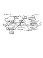
- FIG. 20 shows a configuration example of a communication system using the PMIPv6 protocol.
- a network X5 is, for example, the Internet.
- a network X6 is a network that performs communication using the Proxy Mobile IPv6 protocol (Proxy Mobile IPv6 domain).
- the LMA X3 acts as a proxy for the terminal X1 of the network X6 (PMIPv6 domain) to perform communication between a server X4 of the network X5, which is an external network, and the terminal X1. That is, the LMA X3 receives a packet having the terminal X1 as a destination, as a proxy for the terminal X1, and forwards to the terminal X1. Furthermore it receives a packet transmitted by the terminal X1, and as a proxy for the terminal X1, forwards the packet transmitted by the terminal X1 to the destination of the packet.
- PMIPv6 domain PMIPv6 domain
- the LMA X3 performing communication as a proxy for the terminal X1, a communication partner of the terminal X1 present in the external network can communicate with the terminal X1 in the PMIPv6 domain, without a function for the PMIPv6 protocol being added.
- FIG. 21 shows procedures after the terminal X1 is connected to the network X6 via a MAG-A X2, until handover to a MAG-B X2.
- the MAG-A X2 establishes a link with the terminal X1
- the MAG-A X2 adds an identifier by which the terminal can be uniquely identified, and transmits a Proxy Binding Update (PBU) to the LMA X3.
- the identifier by which the terminal can be uniquely identified may be, for example, a Network Access Identifier (NAI), a MAC address, or the like.
- NAI Network Access Identifier
- MAC address or the like.
- Location information for the terminal is an IP address of a MAG to which the terminal is connected.
- the IP address of the MAG-A2 is used as the location information of the terminal.
- the LMA X3 receives the PBU, with the identifier of the terminal as a key, a Home Network Prefix (HNP) of the terminal is selected, and the HNP, which records the location information of the terminal X1, is a prefix uniquely assigned to each terminal. Then the LMA X3 generates tunnel information so as to enable a packet having the terminal X1 as a destination to be forwarded to the MAG-A X2.
- HNP Home Network Prefix
- the LMA X3 notifies the MAG-A X2 of the HNP using a Proxy Binding Acknowledgment (PBA).
- PBA Proxy Binding Acknowledgment
- encapsulated information is generated so as to enable a packet received from the terminal X1 to be transmitted to the LMA X3.
- the terminal X1 can receive the HNP.
- the terminal X1 obtains its own IP address by, for example, StateLess Address Auto Configuration (SLAAC) or DHCP.
- SLAAC StateLess Address Auto Configuration
- DHCP Dynamic Hossion Control Protocol
- the MAG-B X2 transmits the PBU in order to notify the LMA X3 of the location information of the terminal X1.
- the LMA X3 updates the location information of the terminal X1, and updates the tunnel information. Then the LMA X3 transmits the PBA to the MAG-B X2 as a reception confirmation response.
- the terminal X1 transmits a packet to the server A X4, and the MAG-A X2 receives the packet, encapsulation is performed with a transmission source IP address as MAG-A X2 and a destination IP address as LMA X3, and the packet is transmitted.
- the LMA X3 performs decapsulation, and transmits the packet to the server A X4.
- location information is accessed in order to confirm the location of the terminal X1 (under which MAG is the terminal present?).
- the LMA X3 transmits the packet with the transmission source IP address as LMA X3, and the destination IP address as MAG-A X2.
- the MAG-A X2 performs decapsulation, and forwards the packet to the terminal X1.
- Patent Literature 1 discloses a communication system where it is possible to reflect the state of a path between a terminal and a gateway in configuring a gateway address.
- the literature has a description of a communication apparatus (a wireless LAN base station) of the communication system provided with: information collection means for collecting information of a path to be used between the communication apparatus itself and a connection apparatus that connects a network to which the communication apparatus belongs and another network that differs from this network, and information of the connection apparatus; storage means for storing the collected path information and the information of the connection apparatus; selection means for selecting a connection apparatus based on the stored path information and the information of the connection apparatus, with respect to a communication apparatus that does not possess a path control function within a network; and path control means for controlling a path to the selected connection apparatus.
- a communication apparatus a wireless LAN base station
- a single LMA X3 controls communication between a terminal X1 and an external network. Since the single LMA X3 controls the PMIPv6 domain, in a case where the terminal X1 is present at a location distant from the LMA X3, a communication path for the terminal X1 to access the LMA X3 via MAG-A ... MAG-B X2 is longer than from a terminal that is adjacent to the LMA X3.
- a communication system is disclosed in Patent Literature 1, where, for a communication apparatus (for example, a wireless LAN terminal) that does not have a path control function within a network, a communication apparatus (wireless LAN base station) is provided with selection means for selecting a connection apparatus (gateway) based on stored path information and information of connection apparatuses (gateways), and path control means for controlling a path to the selected connection apparatus (gateway).
- the path information in this literature stops at describing a path between the communication apparatus (for example, the wireless base station) and the connection apparatus (the gateway), and that it is possible to perform packet forwarding between gateways for downstream packets, or to select an optimal gateway for a router.
- a communication system including: a plurality of gateway apparatuses that connect a first network and a second network; and a gateway control apparatus that selects at least one of the plurality of gateway apparatuses, based on information related to location in the second network of a terminal that communicates with the first network via at least one of the plurality of gateway apparatuses.
- the system further includes path control means (entity) for controlling the first network so that a packet(s) having the terminal as a destination passes through the selected gateway apparatus(es).
- a gateway control apparatus that selects at least one of a plurality of gateway apparatuses, based on information related to location of a terminal that communicates with a first network, in a second network, via at least one of the plurality of gateway apparatuses that connect the first network and the second network.
- a path control apparatus that is connected to the gateway control apparatus as mentioned above, and that controls the first network so that a packet(s) having the terminal as a destination passes through the selected gateway apparatus(es).
- a communication method comprising: a step of selecting at least one of a plurality of gateway apparatuses, based on information related to location of a terminal that communicates with a first network, in a second network, via at least one of the plurality of gateway apparatuses that connect the first network and the second network; and a step of controlling the first network so that a packet(s) having the terminal as a destination passes through the selected gateway apparatus(es).
- This method is associated with a particular mechanism known as a gateway control apparatus(es) that selects at least one from a plurality of gateway apparatuses that connect a first network and a second network.
- a program that executes on a computer connected to either of a first or second network: a process of selecting at least one of a plurality of gateway apparatuses, based on information related to location of a terminal that communicates with a first network, in a second network, via at least one of the plurality of gateway apparatuses that connect the first network and the second network; and a process of controlling the first network so that a packet(s) having the terminal as a destination passes through the selected gateway apparatus(es).
- this program may be recorded on a computer-readable storage medium which may be non-transitory. That is, the present disclosure may be embodied as a computer program product.
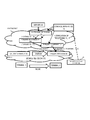
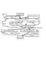
- FIG. 1 is a diagram showing a configuration example of an exemplary embodiment of the present disclosure.
- FIG. 2 is a diagram showing a configuration example of a communication system of a first exemplary embodiment of the present disclosure.
- FIG. 3 is a diagram showing a configuration example of a gateway control apparatus of the first exemplary embodiment of the present disclosure.
- FIG. 4 is a diagram showing a configuration example of a location information DB of the gateway control apparatus of the first exemplary embodiment of the present disclosure.
- FIG. 5 is a diagram showing a configuration example of a local gateway apparatus of the first exemplary embodiment of the present disclosure.
- FIG. 6 is a diagram showing a configuration example of a connection management DB of the first exemplary embodiment of the present disclosure.
- FIG. 1 is a diagram showing a configuration example of an exemplary embodiment of the present disclosure.
- FIG. 2 is a diagram showing a configuration example of a communication system of a first exemplary embodiment of the present disclosure.
- FIG. 3 is a diagram showing a configuration example of
- FIG. 7 is a diagram showing a configuration example of a gateway apparatus of the first exemplary embodiment of the present disclosure.
- FIG. 8 is a diagram showing a configuration example of a location information DB of the gateway apparatus of the first exemplary embodiment.
- FIG. 9 is a diagram describing an operational example of a path control unit provided in the gateway apparatus of the first exemplary embodiment of the present disclosure.
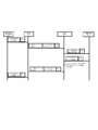
- FIG. 10 is a sequence diagram describing an operational example of the first exemplary embodiment of the present disclosure.
- FIG. 11 is a diagram showing an example of a communication system of a second exemplary embodiment of the present disclosure.
- FIG. 12 is a diagram describing OpenFlow.
- FIG. 13 is a diagram showing a flow entry in OpenFlow.
- FIG. 14 is a diagram showing a configuration example of a control apparatus of the second exemplary embodiment of the present disclosure.
- FIG. 15 is a diagram showing an operational example of the control apparatus of the second exemplary embodiment of the present disclosure.
- FIG. 16 is a diagram showing a configuration example of a third exemplary embodiment of the present disclosure.
- FIG. 17 is a diagram showing a configuration example of a gateway control apparatus in the third exemplary embodiment of the present disclosure.
- FIG. 18 is a diagram showing a configuration example of a policy DB in the third exemplary embodiment of the present disclosure.
- FIG. 19 is a diagram showing an operational example of the third exemplary embodiment of the present disclosure.
- FIG. 20 is a diagram showing a communication system configuration example with regard to PMIPv6.
- FIG. 21 is a sequence diagram showing an example of exchange of control messages of the communication system with regard to PMIPv6.
- FIG. 22 is a sequence diagram showing an example of data communication of the communication system with regard to PMIPv6.
- a mobile network 12 that communicates by using a tunnel formed according to technology such as a mobile IP protocol (MIPv4, MIPv6, PMIPv6, or the like), GPRS Tunneling Protocol (GTP) or the like, and an external network 11 (for example, the internet) are connected via gateway apparatuses 9A to 9N (where the gateway apparatuses 9A to 9N are not particularly distinguished, a description of "gateway apparatus/apparatuses 9" is used).
- MIPv4 mobile IP protocol
- PMIPv6, PMIPv6, or the like GPRS Tunneling Protocol
- GTP GPRS Tunneling Protocol
- an external network 11 for example, the internet
- a plurality of the gateway apparatuses 9 are provided in the mobile communication network 12.
- the respective gateway apparatuses 9 form tunnels with a terminal 1, and control communication between the terminal 1 and the external network 11.
- a gateway control apparatus 10 manages correspondence relationships between movement of the terminal 1 and the gateway apparatuses 9. Accompanying movement of the terminal 1 in the mobile communication network 12, the gateway control apparatus 10 selects a gateway apparatus (or apparatuses) 9 through which communication passes when the terminal 1 communicates with the external network 11, based on the location of the terminal 1. Therefore, in accordance with the location of the terminal 1, it is possible to avoid having a lengthy communication path in the mobile communication network 12.
- the respective gateway apparatuses 9 and the gateway control apparatus 10 perform control so that communication between the terminal 1 and the external network 11 is continued even if the terminal 1 moves.
- a fixed address that does not change even when the terminal 1 moves and a location address that changes as the terminal 1 moves are assigned to the terminal 1.
- a communication partner that communicates with the terminal 1 uses a fixed address that does not change even when the terminal moves, when communicating with the terminal 1.
- a packet transmitted/received between the gateway apparatus(es) 9 and the terminal 1 is encapsulated with a location address that depends on the location of the terminal 1.
- the respective gateway apparatuses 9 perform decapsulation according to the location address and forward to the external network 11.
- the respective gateway apparatuses 9 encapsulate the packet according to the location address and forward to the terminal 1. That is, by encapsulating and decapsulating a packet(s), the respective gateway apparatuses 9 establish a logical tunnel with the terminal 1.
- the gateway control apparatus 10 selects a gateway apparatus(es) 9 where a non-lengthy path is realized based on the location of the terminal 1, from among the plurality of gateway apparatuses 9 present in the mobile communication network 12.
- path control means (or entity) 21 of FIG. 1 controls the external network 11 so that a packet having the terminal 1 as a destination is forwarded to the gateway apparatus(es) 9 corresponding to the terminal 1.
- the path control means (entity) 21 controls a forwarding path of the external network 11 so that a packet(s) having the terminal 1 as a destination is forwarded to the gateway apparatus(es) 9 corresponding to the terminal 1.
- the path control means (entity) 21 may instruct a packet(s) forwarding apparatus (switch or router) of the external network 11, so that the packet having the terminal 1 as a destination is forwarded to the gateway apparatus 9.
- the path control means (entity) 21 may be a logical entity implemented by software. That is, in the communication system of FIG. 1, the path control means (entity) 21 can operate in various physical entities, such as packet forwarding apparatuses forming the gateway apparatus 9, the gateway control apparatus 10, and the external network 11.
- the path control means (entity) 21, for example, may control a switch or router of the external network 11 so that a packet having the fixed address of the terminal 1 as a destination is forwarded to the address of the gateway apparatus 9 corresponding to the terminal 1.
- the path control apparatus 21 may control the switch or router by changing a routing table of a switch or router of the external network 11.
- path control means (entity) 21 is not limited the abovementioned operations, and includes every type of transformation and modification that a person skilled in the art can realize, in accordance with technological concepts thereof.
- FIG. 2 is a diagram showing a configuration example of a communication system of the first exemplary embodiment of the present disclosure.
- a terminal 1 a terminal 1
- a server A 4 an L2 network 14, and a mobile network 15 are shown.
- a plurality of gateway apparatuses 9, a gateway control apparatus 10, and a plurality of local gateway control apparatuses 13A and 13B are arranged in the mobile network 15; note that in FIG. 2, only one terminal is shown for simplicity, but a plurality of terminals may be present under the control of the mobile network 15.
- the terminal 1 communicates with the server A 4 of the L2 network 14 via a gateway 9.
- a location identifier that changes along with movement and an inherent identifier that does not change with movement are assigned to the terminal 1.
- the location identifier for example, is an IP address of the local gateway apparatus 13 to which the terminal 1 is connected, an IP address obtained from a DHCP (Dynamic Host Configuration Protocol) server of a network to which the terminal 1 is connected, or the like.
- a communication system may also be considered which has a configuration where functionality of the local gateway apparatus 13 is provided in the terminal 1, and the local gateway apparatus 13 is not present (for example, Client Mobile IP (CMIP)).
- CMIP Client Mobile IP
- the location identifier of the terminal 1 is an IP address obtained from the DHCP of a network to which the terminal 1 connects after each movement.
- the inherent identifier of the terminal 1 is, for example, an IP address assigned to the terminal 1, or a Home Network Prefix (HNP).
- HNP Home Network Prefix
- the gateway control apparatus 10 selects a gateway apparatus (apparatuses) 9 through which communication passes when the terminal 1 communicates with the L2 network 14, based on the location of the terminal 1. For example, the gateway control apparatus(es) 10 switches the gateway apparatus(es) 9 when the terminal 1 moves and changes location.
- the location of the terminal 1, for example, is determined based on the local gateway apparatus 13 to which the terminal 1 is connected, that is, its location in the L2 network 14.
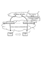
- FIG. 3 is a diagram showing an example of a configuration of a gateway control apparatus 10 of the first exemplary embodiment of the present disclosure.
- the gateway control apparatus 10 includes a selection unit 100, a control unit 101, a location information database (location information DB) 102, and a gateway management database (GW management DB) 103.
- location information database location information DB
- GW management DB gateway management database
- the control unit 101 receives the location identifier of the terminal 1 from the terminal 1 or the local gateway apparatus 13, to be stored in the location information DB 102.
- the location information DB 102 as shown in FIG. 4 for example, associates and manages the inherent identifier of the terminal 1 and the received location identifier (in the example of FIG. 4, the IP address of the local gateway apparatus 13 to which the terminal is connected).
- the control unit 101 receives the location identifier from the terminal 1 or the local gateway apparatus 13. It is to be noted that in the present exemplary embodiment a description is given with an example where the location identifier is the IP address of the local gateway apparatus 13 to which the terminal 1 is connected.
- the selection unit 100 selects corresponding gateway apparatuses 9, with regard to respective terminals connected to the mobile network 15.
- the selection unit 100 selects a gateway apparatus(es) 9 through which the terminal communicates with the L2 network 14, based on the location of the terminal connected to the mobile network 15. For example, the selection unit 100 refers to the location identifier of the terminal 1 stored in the location information DB 102, to select the gateway apparatus 9.
- the selection unit 100 recognizes the location of the local gateway apparatus 13 to which the terminal 1 is connected, from the IP address of the local gateway apparatus 13, which is the location identifier.
- the selection unit 100 for example, recognizes a distance between the local gateway apparatus 13 and the gateway apparatus 9, based on the number of hops and RTT (Round Trip Time) between the local gateway apparatus 13 and the gateway apparatus 9.
- the selection unit 100 for example, selects a gateway apparatus 9 where the distance between the local gateway apparatus 13 and the gateway apparatus 9 is shortest.
- the selection unit 100 may give consideration also to the distance from the gateway apparatus 9 to an apparatus (for example, the server A 4) on the L2 network 14, which is a communication partner of the terminal, to select the gateway apparatus 9.
- the selection unit 100 for example, recognizes the distance based on the number of hops and the RTT (Round Trip Time) between the gateway apparatus 9 and the L2 network 14.
- the selection unit 100 may select the gateway apparatus 9 based on loads on the respective gateway apparatuses 9.
- the selection unit 100 for example, monitors the loads on the respective gateway apparatuses 9 by monitoring congestion states of traffic passing through the respective gateway apparatuses 9.
- the selection unit 100 may select the gateway apparatus 9 based on communication quality between the local gateway apparatus(es) 13 and the gateway apparatus(es) 9.
- the selection unit 100 for example, monitors packet loss rate between the local gateway apparatus 13 and the gateway apparatuses 9, and monitors communication quality.
- the selection unit 100 may make a selection combining a plurality of elements such as the number of hops between the local gateway apparatus 13 and the gateway apparatuses 9, and the loads on the gateway apparatuses 9.
- the combination of a plurality of elements is not limited to the combination described above.
- the number of the local gateway apparatus(es) or gateway apparatus(es) located on a path depicted in Fig. 2 is not limited to the illustrated "one" which is merely shown for simplified schematic illustration.
- the selection unit 100 stores a correspondence relationship (on a selected path) between the selected gateway apparatus 9 and the terminal 1, in the GW management DB 103.
- the selection unit 100 notifies the local gateway apparatus 13 of the correspondence relationship between the selected gateway apparatus 9 and the terminal 1.
- the control unit 101 notifies respective selected gateway apparatuses 9 of correspondence relationships between terminals corresponding to the selected gateway apparatuses 9 and the local gateway apparatuses 13 to which the terminals are connected.
- the local gateway apparatus 13 assumes a role of a gateway for the terminal 1 to access the mobile network 15.
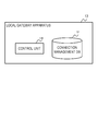
- FIG. 5 shows a configuration example of the local gateway apparatus 13 of the first exemplary embodiment of the present disclosure.
- the local gateway apparatus 13 includes the control unit 130 and the connection management database (connection management DB) 131.
- the local gateway apparatus 13 communicates with the gateway apparatus 9 instead (in place) of the terminal 1. Specifically, the control unit 130 receives a correspondence relationship between the terminal 1 and the gateway apparatus 9, from the gateway control apparatus 10, and stores the relationship in the connection management DB 131. That is, by referring to the connection management DB 131, the local gateway apparatus 13 recognizes the gateway apparatus 9 that is to forward the traffic of the terminal to which the local gateway apparatus 13 itself is connected.
- FIG. 6 shows a configuration example (table) of the connection management DB 131.
- the inherent identifier of the terminal 1 and the IP address of the gateway apparatus 9 are associated and stored.
- control unit 130 refers to the connection management DB 131 to encapsulate/decapsulate packet(s) transmitted/received between the terminal 1 and the gateway apparatus 9 selected by the gateway control apparatus 10.
- the control unit 130 performs encapsulation such that the transmission source of the packet is the local gateway apparatus 13, and the destination is the gateway apparatus 9 (the gateway apparatus 9 corresponding to the terminal 1). That is, the control unit 130 forms a logical tunnel between the local gateway apparatus 13 to which the terminal 1 is connected, and the gateway apparatus 9 selected by the gateway control apparatus 10 for the terminal 1.
- the control unit 130 On receiving a packet from the gateway apparatus 9, the packet being encapsulated so as to have the gateway apparatus 9 as a transmission source and the local gateway apparatus 13 as a destination, for example, the control unit 130 decapsulates the packet.
- the control unit 130 refers to the destination address of the packet after decapsulation, and transmits the packet to a terminal corresponding to the destination address.
- the gateway apparatus 9 functions as a gateway for communication between the L2 network 14 and a terminal of the mobile network 15.
- FIG. 7 shows a configuration example of the gateway apparatus 9 of the first exemplary embodiment of the present disclosure.
- the gateway apparatus 9 includes a path control unit 90, a control unit 91, and a location information database (location information DB) 92.
- the control unit 91 receives correspondence relationships between terminals that communicate with the L2 network 14 via the control unit's own gateway apparatus 9, and the local gateway apparatus 13 to which the respective terminals are connected, from the gateway control apparatus 10.
- the control unit 91 stores the received information in the location information DB 92.
- FIG. 8 shows a configuration example (table) of the location information DB 92.
- the inherent identifier of the terminal 1 and the IP address of the local gateway apparatus 13 are associated and stored.
- the control unit 91 refers to the location information DB 92, to encapsulate/decapsulate packet(s) transmitted/received between the local gateway apparatus 13 and the gateway apparatus 9.
- the control unit 91 decapsulates a packet that has been transmitted to the gateway apparatus 9, the packet having been encapsulated by the local gateway apparatus 13, and transmits the packet to the L2 network 14.
- the control unit 91 assigns an L2 header (a header with destination and transmission source as MAC addresses) and transmits. For example, where a packet is transmitted to the server A 4, a header is assigned with the MAC address of the server A 4 as a destination.
- the control unit 91 recognizes the MAC address of the server A 4 in advance, by ARP (Address Resolution Protocol).
- the control unit 91 stores the MAC address of its own gateway apparatus 9 in the transmission source of the L2 header. That is, the gateway apparatus 9 communicates with the L2 network 14 as a proxy for the terminal 1.
- the control unit 91 encapsulates a packet received from the L2 network 14 to have the local gateway apparatus 13 as a destination, and transmits the packet to the local gateway apparatus 13. It is to be noted that, in a case of receiving a packet from the L2 network, the control unit 91 refers to the location information DB 92 and performs encapsulation having as a destination the local gateway apparatus 13 to which a terminal corresponding to the destination IP address of the received packet is connected.
- the path control unit 90 has a function corresponding to path control means (entity) 21 of FIG. 1. That is, in the first exemplary embodiment, the gateway apparatus 9 is provided with a function entity equivalent to the path control means (entity) 21.
- the gateway control apparatus 10 switches over the gateway apparatus(es) 9 through which communication from the terminal 1 passes to the L2 network.
- an apparatus in the L2 network 14 that performs communication with the terminal 1 transmits the packet with a destination of the MAC address of the gateway apparatus 9 that corresponds to the terminal 1. This is because, since the gateway apparatus 9 communicates as a proxy for the terminal 1, the gateway apparatus 9 is seen as a pseudo terminal 1 from an apparatus on the L2 network side.
- an apparatus present on the L2 network 14 for example, a server A 4
- a server A 4 an apparatus present on the L2 network 14
- the path control unit 90 has a function to change the destination MAC address of the packet to be transmitted to the terminal 1, in an apparatus on the L2 network.
- the server A 4 of the L2 network 14 communicates with the terminal 1 via a gateway apparatus 9A.
- the server A 4 has an address table that stores a correspondence between a destination IP address of the terminal 1 and a MAC address corresponding to this IP address.
- the server A 4 stores a MAC address of the gateway apparatus 9A as a MAC address corresponding to the IP address of the terminal 1, in the address table.
- the IP address of the terminal 1 is a
- the MAC address of the gateway apparatus 9A is b.
- the gateway control apparatus 10 switches over from the gateway apparatus 9A to the gateway apparatus 9B.
- the path control unit 90 broadcasts a Gratuitous ARP (below, GARP).
- GARP is an ARP packet, and is used when an IP address is assigned to a host, to confirm whether or not another host already has the same IP address.
- the path control unit 90 utilizes the GARP (for ARP), in order to make an apparatus on the L2 network 14 recognize the MAC address of the gateway apparatus 9 after switching.
- the IP address of the terminal 1 and the MAC address of the gateway apparatus 9 are stored in the GARP.
- the path control unit 90 transmits the GARP packet to an apparatus on the L2 network.
- the apparatus namely, the server A 4
- the apparatus that receives the GARP packet changes a MAC address corresponding to the IP address a of the terminal 1, changing from the MAC address b of the gateway apparatus 9A to a MAC address c of the gateway apparatus 9B.
- respective parts or elements (processing means) of the gateway control apparatus 10, the local gateway apparatus 13, and the gateway apparatus 9 shown in the respective drawings described above can also be implemented by a computer program that executes the abovementioned respective processes in a computer configured from these apparatuses using software thereof.
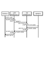
- FIG. 10 is a sequence diagram representing an operation in which the terminal 1 communicates with the server A 4 of the L2 network 14, via a local gateway apparatus (LGW apparatus) 13 and a gateway apparatus (GW apparatus) 9.
- LGW apparatus local gateway apparatus
- GW apparatus gateway apparatus
- the terminal 1 transmits a packet (packet X) having the IP address of the server A 4 as a destination and the IP address of the terminal 1 as a transmission source, to the local gateway apparatus 13 (step S001).
- the local gateway apparatus 13 encapsulates the packet X with the IP address of the gateway apparatus 9 and the IP address of the local gateway apparatus, to generate a packet Y (step S002).
- the packet Y has the IP address of the gateway apparatus 9 as a destination, and the IP address of the local gateway apparatus 13 as a source.
- the local gateway apparatus 13 transmits the generated packet Y to the gateway apparatus 9 (step S003).
- the gateway apparatus 9 decapsulates the encapsulated packet Y (step S004).
- the gateway apparatus 9 transmits a packet Z obtained by adding an L2 header to the decapsulated packet, to the L2 network 14 (step S005).
- the L2 header has a MAC address of the server A 4 as a destination and a MAC address of the gateway apparatus 9 as a transmission source.
- the gateway apparatus 9 recognizes the MAC address of the server A 4 in advance, by an ARP.
- the packet Z reaches the server A 4, and the server A 4 transmits the packet z as a response (step S006).
- the gateway apparatus 9 receives the packet z having the terminal 1 as a destination, from the server A 4.
- the packet z is an L2 packet having the MAC address of the server A 4 as a transmission source, and the MAC address of the gateway apparatus 9 as a destination. It is to be noted that the destination IP address of the packet z is the IP address of the terminal 1.
- the gateway apparatus 9 removes the L2 header of the packet z, and encapsulates the packet (step S007).
- the gateway apparatus 9 generates a packet y by encapsulation.
- the packet y has the IP address of the local gateway apparatus 13 as a destination, and the IP address of the gateway apparatus 9 as a transmission source.
- the gateway apparatus 9 transmits the generated packet y to the local gateway apparatus 13 (step S008).
- the local gateway apparatus 13 decapsulates the packet y, and generates a packet x (step S009).
- the local gateway apparatus 13 transmits the packet x to the terminal 1 (step S010).
- the decapsulated packet has the IP address of the terminal 1 as a destination and the IP address of the server A 4 as a transmission source.
- a communication path at this time is optimized in accordance with the location of the terminal 1, as shown in FIG. 9.
- FIG. 11 is a diagram showing an example of a communication system of the second exemplary embodiment of the present disclosure.
- a terminal 1, a network E 18, and a mobile network 15 are shown.
- Forwarding apparatuses 17A, 17B, and 17C (below, where the forwarding apparatuses 17A, 17B, and 17C are not particularly distinguished, a term of "forwarding apparatus 17" as a singular form is used for simplicity of elucidation, which also represents a plural form), a control apparatus 16, and a server A 4 are arranged in the network E 18.
- Gateway apparatuses 9, local gateway apparatuses 13, and a gateway control apparatus 22 are arranged in the mobile network 15.
- FIG. 12 shows an outline of a communication system configured according to the OpenFlow technology. It is to be noted that a flow is a sequence of communication packet groups having a prescribed attribute.
- An OpenFlow switch 20 is a network switch that uses the OpenFlow technology.
- An OpenFlow controller 19 is an information processing apparatus that controls the OpenFlow switch(es) 20.
- the OpenFlow switch 20 communicates with the OpenFlow controller via a secure channel 191 configured between the OpenFlow controller 19 and the OpenFlow switch(es) 20.
- the OpenFlow controller 19 performs configuration of a flow table 201 of the OpenFlow switch 20 via the secure channel 191.
- the secure channel 191 is a communication path in which a measure is taken to prevent interception or falsification of communication between the switch and controller.
- FIG. 13 is a configuration example of respective entries (flow entries) of the flow table 201.
- a flow entry is configured by Match Fields for matching information (for example, destination IP address, VLAN ID, or the like) included in a header of a packet received by the switch, Counters, being statistical information for respective packet flows, and Instructions that specify a processing method for a packet matching a matching rule.
- the OpenFlow switch 20 On receiving a packet, the OpenFlow switch 20 refers to the flow table 201.
- the OpenFlow switch 20 searches for a flow entry having matching rules (Match Fields) that match the header information of a received packet.
- the OpenFlow switch 20 processes the received packet in accordance with a processing method defined in an instruction field of the retrieved entry.
- the processing method for example, defines "forward a received packet from a prescribed port", "drop a received packet", or "rewrite part of the header of a received packet and forward from a prescribed port".
- the OpenFlow switch 20 forwards the received packet to the OpenFlow controller 19, via the secure channel 191.
- the OpenFlow switch 20 requests the controller to configure a flow entry specifying a processing method of the received packet.
- the OpenFlow controller 19 determines a processing method for the received packet, and configures a flow entry including the determined processing method, in the flow table 201. Thereafter, the OpenFlow switch 20 processes subsequent packets belonging to the same flow as the received packet, according to the configured flow entry.
- the forwarding apparatus 17 of FIG. 11 includes a function that is equivalent to the OpenFlow switch 20.
- the network E 18 is a communication network that includes at least some of the forwarding apparatuses 17.
- the control apparatus 16 includes a function that is equivalent to the OpenFlow controller 19.
- the control apparatus 16 operates as the path control means (entity) 21 of FIG. 1, and is provided with means adapted to communicate with the gateway control apparatus 10.
- FIG. 14 shows a configuration example of the control apparatus 16.
- FIG. 14 is an example, and the configuration of the control apparatus 16 is not limited to the example of FIG. 14.
- a processing rule database (processing rule DB) 168 stores a packet processing rule for configuring in the forwarding apparatus 17. It is to be noted that the configuration of the packet processing rule is the same as the configuration of the flow entry shown in FIG. 13.
- a node communication unit 161 communicates with the forwarding apparatus 17 and the gateway control apparatus 22.
- a control message processing unit 162 transmits a control message received via the node communication unit 161 to a calculation unit 163 and a DB management unit 167 of the control apparatus 16, and also transmits a packet processing rule generated by the calculation unit 163 to the forwarding apparatus 17 via the node communication unit 161.
- a topology management unit 164 manages network topology, based on connection relationships of the forwarding apparatus 17 collected via the node communication unit 161 and information of the terminal 1 and the gateway apparatus 9 to which the terminal 1 is connected, from the gateway control apparatus 22.
- the managed network topology is a piece of topology information of the network E 18 and connection relationships of apparatuses connected to the network E 18, for example, the gateway apparatuses 9.
- the topology management unit 164 receives an inherent identifier of the terminal 1 and an identifier (IP address, MAC address, or the like) of the gateway apparatus 9 corresponding to the terminal 1, from the gateway control apparatus 22. Based on this information, the topology management unit 164 updates the topology information.
- a location management unit 165 performs management as to which forwarding apparatus present in the network E 18 a gateway apparatus 9, which is passed through when the terminal 1 accesses the network E 18, is under the control of.
- the calculation unit 163 determines a forwarding path of a packet based on the network topology, and packet processing to be executed in a forwarding apparatus 17 in the forwarding path. That is, the calculation unit 163 calculates a forwarding path of the packet, and determines a packet processing rule corresponding to the forwarding path.
- the calculation unit 163 fulfills a role equivalent to the path control means (entity) 21.
- the calculation unit 163 obtains a forwarding apparatus 17 connected to this gateway apparatus 9 from the topology management unit 164.
- the calculation unit 163 records the inherent identifier of the terminal 1 and an identifier of the forwarding apparatus 17 connected to the gateway apparatus 9 corresponding to the terminal 1, as a set, in the location management unit 165. Thereafter, the calculation unit 163 accesses the topology management unit 164 and the location management unit 165, confirms the topology information and the location of the terminal, and determines a forwarding path of a packet having the terminal 1 as a destination.
- the calculation unit 163 confirms the forwarding apparatus 17 to which a gateway apparatus corresponding to the terminal 1 is connected by accessing the location management unit 165, and the calculation unit 163 calculates a forwarding path as far as the forwarding apparatus 17 and determines a packet processing rule corresponding to the calculated forwarding path.
- the calculation unit 163 notifies the forwarding apparatus 17 in the forwarding path of the packet, of the determined packet processing rule.
- the packet processing rule determined by the calculation unit 163 is also transmitted to the DB management unit 167 and is reflected in the processing rule DB 168.
- the gateway control apparatus 22 notifies the control apparatus 16 that a gateway apparatus has switched from the gateway apparatus 9A to the gateway apparatus 9B by a handover of the terminal 1.
- the control apparatus 16 controls the forwarding apparatus 17 of the network E 18 so that a packet having the terminal 1 as a destination is forwarded to the gateway apparatus 9B after switching.
- the calculation unit 163 determines a packet processing rule to be notified to each forwarding apparatus on the forwarding path.
- the calculation unit 163 notifies the forwarding apparatus 17A of a processing rule for forwarding the packet having the terminal 1 as a destination to the forwarding apparatus 17B.
- the calculation unit 163 notifies the forwarding apparatus 17B of a processing rule for forwarding the packet having the terminal 1 as a destination to the forwarding apparatus 17C.
- the calculation unit 163 notifies the forwarding apparatus 17C of a processing rule for forwarding the packet having the terminal 1 as a destination to the forwarding apparatus 9B.
- the DB management unit 167 records a packet processing rule determined by the calculation unit 163 in the processing rule DB 168.
- the DB management unit 167 transmits the packet processing rule to the forwarding apparatus 17, in response to a request to transmit the packet processing rule from the forwarding apparatus 17.
- the control message processing unit 162 analyzes a control message (for example, a request to configure a packet processing rule) received from the forwarding apparatus 17, and performs processing corresponding to the control message.
- the control message processing unit 162 generates a message (for example, a message for configuring a packet processing rule) to be transmitted to the forwarding apparatus 17.
- An apparatus in a mobile network 15 of the second exemplary embodiment is the same as an apparatus of the first exemplary embodiment.
- the gateway control apparatus 22 of the present exemplary embodiment communicates with the control apparatus 16.
- the gateway control apparatus 22 and the control apparatus 16 were described as different apparatuses, but the two apparatuses can also be implemented as one apparatus. That is, the functionality of the control apparatus 16 may be added to the gateway control apparatus 22, or a configuration in which the gateway control apparatus 22 controls the forwarding apparatus 17 may be used.
- a communication partner of the terminal 1 is not limited to a terminal within the network E 18 and, for example, a case is also possible where the network E 18 is connected to an external network, and the terminal 1 communicates with an apparatus of this external network via the network E 18.
- FIG. 16 is a diagram showing a configuration example of a third exemplary embodiment of the present disclosure.
- a mail server 26 an HTTP (Hyper Text Transfer Protocol) server 27, a gateway apparatus-SMTP 9SA, a gateway apparatus-HTTP 9HA, a gateway apparatus-SMTP 9SB, a gateway apparatus-HTTP 9HB, a local gateway apparatus 13A, a local gateway apparatus 13B, a gateway control apparatus 32, a forwarding apparatus 17A, a forwarding apparatus 17B, and a control apparatus 16 are shown.
- HTTP Hyper Text Transfer Protocol
- the gateway apparatus-HTTP 9HA and the gateway apparatus-HTTP 9HB are gateway apparatuses for HTML (Hyper Text Markup Language).
- the gateway apparatus-SMTP 9SA and the gateway apparatus-SMTP 9SB are gateway apparatuses 9 for email (SMTP; Simple Mail Transfer Protocol).
- SMTP Simple Mail Transfer Protocol
- the gateway control apparatus 32 for example, performs an operation of selecting the gateway apparatus 9 for each communication flow (or each packet or each group of packets).
- FIG. 16 shows a state in which the terminal 1 is connected to the local gateway apparatus 13A and is accessing a mobile network 15.
- the gateway control apparatus 32 selects a gateway apparatus 9 to be used for each communication flow, based on a prescribed reference.
- the prescribed reference for example, is the distance from the local gateway apparatus 13, or the load on a gateway apparatus 9.
- FIG. 17 is a diagram showing a configuration example of a gateway control apparatus 32 of the present exemplary embodiment.
- a policy database (policy DB) 320 is added to a configuration of a gateway control apparatus 10 of the first exemplary embodiment. Since the configuration otherwise is similar to the configuration described in the first exemplary embodiment and FIG. 3, a detailed description is omitted.
- the gateway control apparatus 32 manages a gateway apparatus 9 selected for each communication flow by the policy DB 320.
- the policy DB 320 is a database that associates and manages, for each respective terminal, local gateway apparatuses to which respective terminals are connected, and for each type of communication flow, gateway apparatuses by which each local gateway apparatus is to forward packet(s) corresponding to the respective communication flows.
- the selection unit 100 When a selection unit 100 of the gateway control apparatus 32 selects a gateway apparatus 9 for each communication flow, the selection unit 100 updates the policy DB 320.
- the gateway control apparatus 32 notifies the respective local gateway apparatuses 13 of the gateway apparatuses 9 for forwarding traffic of respective terminals connected to the respective local gateway apparatuses 13. That is, the gateway control apparatus 32 refers to the policy DB 320 and specifies the gateway apparatuses 9 for forwarding traffic of the terminals for each communication flow, to the local gateway apparatuses 13.
- the gateway control apparatus 32 notifies the control apparatus 16 of the network E 18, of the gateway apparatuses 9 for forwarding packets with destinations of the respective terminals. That is, the gateway control apparatus 32 refers to the policy DB 320, and specifies the gateway apparatuses 9 for forwarding packets with destinations of the respective terminals, for each communication flow, to the control apparatus 16.
- the gateway control apparatus 32 for example, with regard to a packet having the terminal 1 as a destination, instructs the control apparatus 16 so that a packet belonging to an SMTP communication flow is forwarded to the gateway apparatus-SMTP 9SA, and a packet belonging to an HTTP communication flow is forwarded to the gateway apparatus-HTTP 9HA.
- the control apparatus 16 notifies each forwarding apparatus 17 of the network E 18 of a processing rule, based on an instruction from the gateway control apparatus 32.
- control apparatus 16 notifies each forwarding apparatus 17 of a processing rule specifying a forwarding method of a packet having the terminal 1 as a destination, the packet belonging to an HTTP communication flow.
- the control apparatus 16 determines a forwarding path of an HTTP packet having the terminal 1 as a destination, being a forwarding path that forwards in a sequence of the forwarding apparatuses 17A, 17B, and 17C.
- the control apparatus 16 determines a packet processing rule to be notified to each forwarding apparatus in the forwarding path.
- the control apparatus 16 notifies the forwarding apparatus 17A of a processing rule for forwarding an HTTP packet having the terminal 1 as a destination, to the forwarding apparatus 17B.
- the control apparatus 16 notifies the forwarding apparatus 17B of a processing rule for forwarding an HTTP packet having the terminal 1 as a destination, to the forwarding apparatus 17C.
- the calculation unit 16 notifies the forwarding apparatus 17C of a processing rule for forwarding a packet having the terminal 1 as a destination, to the gateway apparatus-HTTP 9HA.
- the forwarding apparatuses of the network E 18 can forward a packet to an appropriate gateway apparatus 9.
- the gateway apparatuses 9 used are separated for respective protocols and a plurality thereof are used simultaneously, but there is no limitation thereto.
- a plurality interfaces may be installed in the terminal 1, a gateway apparatus 9 may be prepared for each interface, and the gateway apparatus 9 may be used in accordance with an IF used in the terminal 1.
- the terminal 1 may have WiFi and LTE (Long Term Evolution) interfaces installed, the gateway apparatuses 9 may be used according to each IF thereof, and the plurality of gateway apparatuses 9 may be used simultaneously.
- LTE Long Term Evolution
- ⁇ First mode> See the communication system according to a first aspect described above.
- ⁇ Second mode> The communication system according to the first mode, wherein the gateway control apparatus selects a gateway apparatus in accordance with movement of the terminal, and the path control means (entity) switches a forwarding destination of a packet having the terminal as a destination to the selected gateway apparatus(es).
- ⁇ Third mode> The communication system according to the first or second mode, wherein the gateway control apparatus selects a plurality of gateway apparatuses corresponding to the terminal, and uses the selected plurality of gateway apparatuses in respective right places based on a prescribed reference.
- ⁇ Fourth mode> The communication system according to any one of the first to third modes, wherein the path control means (entity) controls the first network by notifying the first network of an identifier of the gateway apparatus through which a packet(s), having the terminal as a destination, passes.
- ⁇ Fifth mode> The communication system according to any one of the first to third modes, wherein the path control means(entity) controls the first network by instructing a communication apparatus that forwards a packet in the first network, to forward a packet(s) having the terminal as a destination to the selected gateway apparatus.
- ⁇ Sixth mode> The communication system according to any one of the first to third modes, wherein the path control means calculates a communication path by which a packet having the terminal as a destination reaches the selected gateway apparatus, and controls the first network by instructing the communication apparatus in the communication path to forward the packet(s) having the terminal as a destination following the communication path.
- the gateway control apparatus selects the gateway apparatus based on location information in the second network, of the terminal, notified by the terminal.
- ⁇ Eighth mode> The communication system according to any one of the first to sixth modes, wherein a local gateway apparatus is provided to communicate with the gateway apparatus in place of the terminal in the second network, and the gateway control apparatus selects the gateway apparatus based on location information of the terminal notified by the local gateway apparatus.
- ⁇ Ninth mode> See the gateway control apparatus according to a second aspect described above.
- ⁇ Tenth mode> See the path control apparatus according to a third aspect described above.
- ⁇ Eleventh mode> See the communication method according to a fourth aspect described above.
- ⁇ Twelfth mode> See the program according to a fifth aspect described above.
Landscapes
- Engineering & Computer Science (AREA)
- Computer Networks & Wireless Communication (AREA)
- Signal Processing (AREA)
- Databases & Information Systems (AREA)
- Mobile Radio Communication Systems (AREA)
- Data Exchanges In Wide-Area Networks (AREA)
Abstract
Priority Applications (3)
| Application Number | Priority Date | Filing Date | Title |
|---|---|---|---|
| JP2014542424A JP6179523B2 (ja) | 2012-03-01 | 2012-10-30 | 通信システム、ゲートウェイ制御装置、経路制御装置、通信方法及びプログラム |
| US14/381,509 US20150016340A1 (en) | 2012-03-01 | 2012-10-30 | Communication System, Gateway Control Apparatus, Path Control Apparatus, Communication Method and Program |
| EP12869881.8A EP2820884A4 (fr) | 2012-03-01 | 2012-10-30 | Système de communication, appareil de commande de passerelle, appareil de commande de chemin, procédé de communication et programme |
Applications Claiming Priority (2)
| Application Number | Priority Date | Filing Date | Title |
|---|---|---|---|
| JP2012-045836 | 2012-03-01 | ||
| JP2012045836 | 2012-03-01 |
Publications (1)
| Publication Number | Publication Date |
|---|---|
| WO2013128513A1 true WO2013128513A1 (fr) | 2013-09-06 |
Family
ID=49081778
Family Applications (1)
| Application Number | Title | Priority Date | Filing Date |
|---|---|---|---|
| PCT/JP2012/006950 WO2013128513A1 (fr) | 2012-03-01 | 2012-10-30 | Système de communication, appareil de commande de passerelle, appareil de commande de chemin, procédé de communication et programme |
Country Status (4)
| Country | Link |
|---|---|
| US (1) | US20150016340A1 (fr) |
| EP (1) | EP2820884A4 (fr) |
| JP (1) | JP6179523B2 (fr) |
| WO (1) | WO2013128513A1 (fr) |
Cited By (8)
| Publication number | Priority date | Publication date | Assignee | Title |
|---|---|---|---|---|
| US20150169345A1 (en) * | 2013-12-18 | 2015-06-18 | International Business Machines Corporation | Software-defined networking (sdn) for management of traffic between virtual processors |
| KR101533027B1 (ko) * | 2014-10-29 | 2015-07-02 | 성균관대학교산학협력단 | 소프트웨어 정의 네트워크 기반 프록시 모바일 IPv6에서 핸드오버를 지원하는 오픈플로우 컨트롤러 및 그 제어 방법 |
| CN105325031A (zh) * | 2014-05-30 | 2016-02-10 | 华为技术有限公司 | 一种业务路径变更方法及装置 |
| JP2016139908A (ja) * | 2015-01-27 | 2016-08-04 | 日本電気株式会社 | 通信システム、通信ノード、制御装置、通信制御方法、及び、プログラム |
| GB2538551A (en) * | 2015-05-21 | 2016-11-23 | Samsung Electronics Co Ltd | Internet protocol address preservation in mobile operator networks |
| JP2017509222A (ja) * | 2013-12-20 | 2017-03-30 | 株式会社Nttドコモ | モビリティアンカのモビリティ |
| EP2999166A4 (fr) * | 2014-06-30 | 2017-04-12 | NEC Platforms, Ltd. | Dispositif de passerelle, système de communication, procédé de communication et programme de communication |
| US11044600B2 (en) | 2017-02-15 | 2021-06-22 | Huawei Technologies Co., Ltd. | Apparatus and method for performing local breakout service on use requipment |
Families Citing this family (8)
| Publication number | Priority date | Publication date | Assignee | Title |
|---|---|---|---|---|
| CN104427567B (zh) * | 2013-09-04 | 2019-10-01 | 南京中兴新软件有限责任公司 | 实现ip移动的方法及系统、接入点设备、无线接入控制器 |
| WO2017106491A1 (fr) * | 2015-12-15 | 2017-06-22 | MindTop, Inc. | Réseaux d'amélioration de la confidentialité |
| JP6779667B2 (ja) * | 2016-05-30 | 2020-11-04 | 株式会社東芝 | 無線通信装置、無線通信方法、制御システム及びコンピュータプログラム |
| WO2018090230A1 (fr) | 2016-11-16 | 2018-05-24 | 华为技术有限公司 | Procédé et dispositif de migration de données |
| US20180205891A1 (en) * | 2017-01-18 | 2018-07-19 | Jerry L. Conway, Sr. | Multi-camera dynamic imaging systems and methods of capturing dynamic images |
| JP6894872B2 (ja) * | 2018-07-20 | 2021-06-30 | Kddi株式会社 | ネットワーク装置間を最短経路の中継装置によって中継するデータ中継方法 |
| US10743219B2 (en) * | 2018-12-11 | 2020-08-11 | Bandwidth, Inc. | Geographic routing via labels in SIP redirect |
| JP7024015B2 (ja) * | 2020-07-13 | 2022-02-22 | 株式会社東芝 | ビル機器制御システムおよびビル機器制御方法 |
Citations (4)
| Publication number | Priority date | Publication date | Assignee | Title |
|---|---|---|---|---|
| JP2005236767A (ja) | 2004-02-20 | 2005-09-02 | Ntt Docomo Inc | 通信装置、中継装置及び通信システム並びに通信方法 |
| WO2009036806A1 (fr) * | 2007-09-20 | 2009-03-26 | Telefonaktiebolaget Lm Ericsson (Publ) | Procédé et appareil pour l'itinérance entre des réseaux de communication |
| WO2009118980A1 (fr) * | 2008-03-25 | 2009-10-01 | 株式会社日立コミュニケーションテクノロジー | Système de radiocommunication, contrôleur de passerelle et station de base |
| WO2011034173A1 (fr) * | 2009-09-18 | 2011-03-24 | 日本電気株式会社 | Système de communication et procédé de commande de communication |
Family Cites Families (7)
| Publication number | Priority date | Publication date | Assignee | Title |
|---|---|---|---|---|
| WO2006109462A1 (fr) * | 2005-04-05 | 2006-10-19 | Matsushita Electric Industrial Co., Ltd. | Système de communication radio et méthode de communication radio |
| US8099112B2 (en) * | 2005-04-18 | 2012-01-17 | Nokia Corporation | Network entity, method and computer program product for dynamically changing a request for location information |
| US20080089305A1 (en) * | 2006-10-13 | 2008-04-17 | Huawei Technologies Co., Ltd. | System and method for broadband mobile access network |
| JP5538544B2 (ja) * | 2009-08-25 | 2014-07-02 | テレフオンアクチーボラゲット エル エム エリクソン(パブル) | モビリティアンカーの移転 |
| US8861426B2 (en) * | 2010-04-16 | 2014-10-14 | Panasonic Intellectual Property Corporation Of America | Path switching system, path switching method, and mobile terminal |
| US8521858B2 (en) * | 2010-06-07 | 2013-08-27 | Verizon Patent Licensing Inc. | Selection of a policy and charging rules function device |
| US8955055B1 (en) * | 2012-09-28 | 2015-02-10 | Juniper Networks, Inc. | Customer extendable AAA framework for network elements |
-
2012
- 2012-10-30 EP EP12869881.8A patent/EP2820884A4/fr not_active Withdrawn
- 2012-10-30 JP JP2014542424A patent/JP6179523B2/ja active Active
- 2012-10-30 US US14/381,509 patent/US20150016340A1/en not_active Abandoned
- 2012-10-30 WO PCT/JP2012/006950 patent/WO2013128513A1/fr active Application Filing
Patent Citations (4)
| Publication number | Priority date | Publication date | Assignee | Title |
|---|---|---|---|---|
| JP2005236767A (ja) | 2004-02-20 | 2005-09-02 | Ntt Docomo Inc | 通信装置、中継装置及び通信システム並びに通信方法 |
| WO2009036806A1 (fr) * | 2007-09-20 | 2009-03-26 | Telefonaktiebolaget Lm Ericsson (Publ) | Procédé et appareil pour l'itinérance entre des réseaux de communication |
| WO2009118980A1 (fr) * | 2008-03-25 | 2009-10-01 | 株式会社日立コミュニケーションテクノロジー | Système de radiocommunication, contrôleur de passerelle et station de base |
| WO2011034173A1 (fr) * | 2009-09-18 | 2011-03-24 | 日本電気株式会社 | Système de communication et procédé de commande de communication |
Non-Patent Citations (1)
| Title |
|---|
| See also references of EP2820884A4 |
Cited By (16)
| Publication number | Priority date | Publication date | Assignee | Title |
|---|---|---|---|---|
| US20150347175A1 (en) * | 2013-12-18 | 2015-12-03 | International Business Machines Corporation | Software-defined networking (sdn) for management of traffic between virtual processors |
| US20150169345A1 (en) * | 2013-12-18 | 2015-06-18 | International Business Machines Corporation | Software-defined networking (sdn) for management of traffic between virtual processors |
| JP2017509222A (ja) * | 2013-12-20 | 2017-03-30 | 株式会社Nttドコモ | モビリティアンカのモビリティ |
| EP3142414A4 (fr) * | 2014-05-30 | 2017-05-17 | Huawei Technologies Co. Ltd. | Procédé et dispositif de changement de chemin de service |
| CN105325031B (zh) * | 2014-05-30 | 2020-01-21 | 华为技术有限公司 | 一种业务路径变更方法及装置 |
| CN105325031A (zh) * | 2014-05-30 | 2016-02-10 | 华为技术有限公司 | 一种业务路径变更方法及装置 |
| RU2669582C2 (ru) * | 2014-05-30 | 2018-10-12 | Хуавэй Текнолоджиз Ко., Лтд. | Способ и устройство смены пути услуги |
| US9961045B2 (en) | 2014-05-30 | 2018-05-01 | Huawei Technologies Co., Ltd. | Service path changing method and apparatus |
| US10375250B2 (en) | 2014-06-30 | 2019-08-06 | Nec Platforms, Ltd. | Gate way device, communication system, communication method, and communication program |
| EP2999166A4 (fr) * | 2014-06-30 | 2017-04-12 | NEC Platforms, Ltd. | Dispositif de passerelle, système de communication, procédé de communication et programme de communication |
| KR101533027B1 (ko) * | 2014-10-29 | 2015-07-02 | 성균관대학교산학협력단 | 소프트웨어 정의 네트워크 기반 프록시 모바일 IPv6에서 핸드오버를 지원하는 오픈플로우 컨트롤러 및 그 제어 방법 |
| JP2016139908A (ja) * | 2015-01-27 | 2016-08-04 | 日本電気株式会社 | 通信システム、通信ノード、制御装置、通信制御方法、及び、プログラム |
| GB2538551A (en) * | 2015-05-21 | 2016-11-23 | Samsung Electronics Co Ltd | Internet protocol address preservation in mobile operator networks |
| GB2538551B (en) * | 2015-05-21 | 2018-11-21 | Samsung Electronics Co Ltd | Internet protocol address preservation in mobile operator networks |
| US10433232B2 (en) | 2015-05-21 | 2019-10-01 | Samsung Electronics Co., Ltd. | Internet protocol address preservation in mobile operator networks |
| US11044600B2 (en) | 2017-02-15 | 2021-06-22 | Huawei Technologies Co., Ltd. | Apparatus and method for performing local breakout service on use requipment |
Also Published As
| Publication number | Publication date |
|---|---|
| JP6179523B2 (ja) | 2017-08-16 |
| JP2015508945A (ja) | 2015-03-23 |
| EP2820884A1 (fr) | 2015-01-07 |
| EP2820884A4 (fr) | 2015-11-25 |
| US20150016340A1 (en) | 2015-01-15 |
Similar Documents
| Publication | Publication Date | Title |
|---|---|---|
| WO2013128513A1 (fr) | Système de communication, appareil de commande de passerelle, appareil de commande de chemin, procédé de communication et programme | |
| JP6508256B2 (ja) | 通信システム、通信装置、制御装置、パケットフローの転送経路の制御方法及びプログラム | |
| CN101268670B (zh) | 能同时使用归属网络和外部网络的多归属移动节点、归属代理及其方法 | |
| CN102934400B (zh) | 通信系统、逻辑信道控制设备、控制设备、通信方法以及程序 | |
| CN102450053B (zh) | 采用ip流移动性的无线数据通信 | |
| EP2361472B1 (fr) | Procédé et appareil à utiliser dans un réseau de communications | |
| Kim et al. | OpenFlow-based Proxy mobile IPv6 over software defined network (SDN) | |
| US20110110354A1 (en) | Node, method, and system for high-rate access to public network from mobile network | |
| US20060209759A1 (en) | Local mobility management in mobile Internet protocol network | |
| JP2009529265A (ja) | 動的ルータ広告を使用する高速ハンドオーバのための方法及びシステム | |
| US10129146B2 (en) | Methods and apparatus for providing mobility in ethernet network | |
| JP6278468B2 (ja) | 移動通信端末の経路制御方法及びシステム | |
| JP5655018B2 (ja) | ハンドオーバ処理システム、及びゲートウェイルータ | |
| Purohith et al. | Network architecture supporting seamless flow mobility between LTE and WiFi networks | |
| KR20140124116A (ko) | 이동 통신 네트워크에서 데이터-패스를 최적화시키는 장치 및 방법 | |
| US20100046558A1 (en) | Header reduction of data packets by route optimization procedure | |
| KR101680137B1 (ko) | Sdn 기반의 단말 이동성 제어 시스템 및 그 방법 | |
| Karimzadeh et al. | Software Defined Networking to support IP address mobility in future LTE network | |
| Ghosh et al. | Performance Evaluation of Optimized Mobile IP Protocol Vis-à-vis Bit Map Indexing Method | |
| US9439127B2 (en) | Method for data transmission and local network entity | |
| Karimzadeh et al. | Double-NAT based mobility management for future LTE networks | |
| US9367514B2 (en) | Communication node and communication method | |
| EP3131245B1 (fr) | Procédé de transmission de données, procédé de mise à jour d'informations de transfert, dispositif de communication et organe de commande | |
| Phoomikiattisak | Mobility as first class functionality: ILNPv6 in the Linux kernel | |
| WO2014205832A1 (fr) | Procédé, passerelle frontière, et dispositif de plan de commande pour une émission de données |
Legal Events
| Date | Code | Title | Description |
|---|---|---|---|
| 121 | Ep: the epo has been informed by wipo that ep was designated in this application |
Ref document number: 12869881 Country of ref document: EP Kind code of ref document: A1 |
|
| WWE | Wipo information: entry into national phase |
Ref document number: 2012869881 Country of ref document: EP |
|
| WWE | Wipo information: entry into national phase |
Ref document number: 14381509 Country of ref document: US |
|
| ENP | Entry into the national phase |
Ref document number: 2014542424 Country of ref document: JP Kind code of ref document: A |
|
| NENP | Non-entry into the national phase |
Ref country code: DE |