WO2013125271A1 - Electrical storage element - Google Patents
Electrical storage element Download PDFInfo
- Publication number
- WO2013125271A1 WO2013125271A1 PCT/JP2013/050943 JP2013050943W WO2013125271A1 WO 2013125271 A1 WO2013125271 A1 WO 2013125271A1 JP 2013050943 W JP2013050943 W JP 2013050943W WO 2013125271 A1 WO2013125271 A1 WO 2013125271A1
- Authority
- WO
- WIPO (PCT)
- Prior art keywords
- abutting member
- electrode body
- skirt
- protrusion
- base
- Prior art date
Links
Images


Classifications
-
- H—ELECTRICITY
- H01—ELECTRIC ELEMENTS
- H01M—PROCESSES OR MEANS, e.g. BATTERIES, FOR THE DIRECT CONVERSION OF CHEMICAL ENERGY INTO ELECTRICAL ENERGY
- H01M10/00—Secondary cells; Manufacture thereof
- H01M10/04—Construction or manufacture in general
- H01M10/0413—Large-sized flat cells or batteries for motive or stationary systems with plate-like electrodes
-
- H—ELECTRICITY
- H01—ELECTRIC ELEMENTS
- H01G—CAPACITORS; CAPACITORS, RECTIFIERS, DETECTORS, SWITCHING DEVICES OR LIGHT-SENSITIVE DEVICES, OF THE ELECTROLYTIC TYPE
- H01G11/00—Hybrid capacitors, i.e. capacitors having different positive and negative electrodes; Electric double-layer [EDL] capacitors; Processes for the manufacture thereof or of parts thereof
- H01G11/22—Electrodes
- H01G11/30—Electrodes characterised by their material
- H01G11/32—Carbon-based
- H01G11/38—Carbon pastes or blends; Binders or additives therein
-
- H—ELECTRICITY
- H01—ELECTRIC ELEMENTS
- H01G—CAPACITORS; CAPACITORS, RECTIFIERS, DETECTORS, SWITCHING DEVICES OR LIGHT-SENSITIVE DEVICES, OF THE ELECTROLYTIC TYPE
- H01G11/00—Hybrid capacitors, i.e. capacitors having different positive and negative electrodes; Electric double-layer [EDL] capacitors; Processes for the manufacture thereof or of parts thereof
- H01G11/66—Current collectors
- H01G11/68—Current collectors characterised by their material
-
- H—ELECTRICITY
- H01—ELECTRIC ELEMENTS
- H01G—CAPACITORS; CAPACITORS, RECTIFIERS, DETECTORS, SWITCHING DEVICES OR LIGHT-SENSITIVE DEVICES, OF THE ELECTROLYTIC TYPE
- H01G11/00—Hybrid capacitors, i.e. capacitors having different positive and negative electrodes; Electric double-layer [EDL] capacitors; Processes for the manufacture thereof or of parts thereof
- H01G11/78—Cases; Housings; Encapsulations; Mountings
- H01G11/82—Fixing or assembling a capacitive element in a housing, e.g. mounting electrodes, current collectors or terminals in containers or encapsulations
-
- H—ELECTRICITY
- H01—ELECTRIC ELEMENTS
- H01M—PROCESSES OR MEANS, e.g. BATTERIES, FOR THE DIRECT CONVERSION OF CHEMICAL ENERGY INTO ELECTRICAL ENERGY
- H01M10/00—Secondary cells; Manufacture thereof
- H01M10/04—Construction or manufacture in general
- H01M10/0431—Cells with wound or folded electrodes
-
- H—ELECTRICITY
- H01—ELECTRIC ELEMENTS
- H01M—PROCESSES OR MEANS, e.g. BATTERIES, FOR THE DIRECT CONVERSION OF CHEMICAL ENERGY INTO ELECTRICAL ENERGY
- H01M10/00—Secondary cells; Manufacture thereof
- H01M10/04—Construction or manufacture in general
- H01M10/0436—Small-sized flat cells or batteries for portable equipment
-
- H—ELECTRICITY
- H01—ELECTRIC ELEMENTS
- H01M—PROCESSES OR MEANS, e.g. BATTERIES, FOR THE DIRECT CONVERSION OF CHEMICAL ENERGY INTO ELECTRICAL ENERGY
- H01M50/00—Constructional details or processes of manufacture of the non-active parts of electrochemical cells other than fuel cells, e.g. hybrid cells
- H01M50/50—Current conducting connections for cells or batteries
- H01M50/531—Electrode connections inside a battery casing
- H01M50/533—Electrode connections inside a battery casing characterised by the shape of the leads or tabs
-
- H—ELECTRICITY
- H01—ELECTRIC ELEMENTS
- H01M—PROCESSES OR MEANS, e.g. BATTERIES, FOR THE DIRECT CONVERSION OF CHEMICAL ENERGY INTO ELECTRICAL ENERGY
- H01M50/00—Constructional details or processes of manufacture of the non-active parts of electrochemical cells other than fuel cells, e.g. hybrid cells
- H01M50/50—Current conducting connections for cells or batteries
- H01M50/531—Electrode connections inside a battery casing
- H01M50/534—Electrode connections inside a battery casing characterised by the material of the leads or tabs
-
- H—ELECTRICITY
- H01—ELECTRIC ELEMENTS
- H01M—PROCESSES OR MEANS, e.g. BATTERIES, FOR THE DIRECT CONVERSION OF CHEMICAL ENERGY INTO ELECTRICAL ENERGY
- H01M10/00—Secondary cells; Manufacture thereof
- H01M10/05—Accumulators with non-aqueous electrolyte
- H01M10/052—Li-accumulators
-
- Y—GENERAL TAGGING OF NEW TECHNOLOGICAL DEVELOPMENTS; GENERAL TAGGING OF CROSS-SECTIONAL TECHNOLOGIES SPANNING OVER SEVERAL SECTIONS OF THE IPC; TECHNICAL SUBJECTS COVERED BY FORMER USPC CROSS-REFERENCE ART COLLECTIONS [XRACs] AND DIGESTS
- Y02—TECHNOLOGIES OR APPLICATIONS FOR MITIGATION OR ADAPTATION AGAINST CLIMATE CHANGE
- Y02E—REDUCTION OF GREENHOUSE GAS [GHG] EMISSIONS, RELATED TO ENERGY GENERATION, TRANSMISSION OR DISTRIBUTION
- Y02E60/00—Enabling technologies; Technologies with a potential or indirect contribution to GHG emissions mitigation
- Y02E60/10—Energy storage using batteries
-
- Y—GENERAL TAGGING OF NEW TECHNOLOGICAL DEVELOPMENTS; GENERAL TAGGING OF CROSS-SECTIONAL TECHNOLOGIES SPANNING OVER SEVERAL SECTIONS OF THE IPC; TECHNICAL SUBJECTS COVERED BY FORMER USPC CROSS-REFERENCE ART COLLECTIONS [XRACs] AND DIGESTS
- Y02—TECHNOLOGIES OR APPLICATIONS FOR MITIGATION OR ADAPTATION AGAINST CLIMATE CHANGE
- Y02E—REDUCTION OF GREENHOUSE GAS [GHG] EMISSIONS, RELATED TO ENERGY GENERATION, TRANSMISSION OR DISTRIBUTION
- Y02E60/00—Enabling technologies; Technologies with a potential or indirect contribution to GHG emissions mitigation
- Y02E60/13—Energy storage using capacitors
-
- Y—GENERAL TAGGING OF NEW TECHNOLOGICAL DEVELOPMENTS; GENERAL TAGGING OF CROSS-SECTIONAL TECHNOLOGIES SPANNING OVER SEVERAL SECTIONS OF THE IPC; TECHNICAL SUBJECTS COVERED BY FORMER USPC CROSS-REFERENCE ART COLLECTIONS [XRACs] AND DIGESTS
- Y02—TECHNOLOGIES OR APPLICATIONS FOR MITIGATION OR ADAPTATION AGAINST CLIMATE CHANGE
- Y02P—CLIMATE CHANGE MITIGATION TECHNOLOGIES IN THE PRODUCTION OR PROCESSING OF GOODS
- Y02P70/00—Climate change mitigation technologies in the production process for final industrial or consumer products
- Y02P70/50—Manufacturing or production processes characterised by the final manufactured product
Definitions
- the present invention relates to an electricity storage device including an electrode body in which a positive electrode plate and a negative electrode plate are laminated, and a current collector connected to the electrode body.
- batteries lithium ion batteries, nickel metal hydride batteries, etc.
- capacitors electric double layer capacitors, etc.
- Possible power storage elements are employed.
- various types of batteries are provided.
- a battery is provided that includes a flat electrode body wound with a positive electrode plate and a negative electrode plate insulated from each other, and a current collector connected to the electrode body.
- the electrode body is wound in a cylindrical shape from the inside so that the separator 23, the negative electrode plate 22, the separator 23, and the positive electrode plate 21 are stacked in this order. By pressing the side surfaces from both sides, they are flattened and deformed. Alternatively, the electrode body is formed by laminating these in a flat shape so that the separator 23, the negative electrode plate 22, the separator 23, and the positive electrode plate 21 are arranged in this order from the inside.
- the positive electrode plate 21 is coated with a positive electrode active material paint on one surface of a positive electrode current collector substrate 21a made of a strip-shaped aluminum foil, dried, and then opposite to the positive electrode current collector substrate 21a.
- a positive electrode active material coating (positive electrode active material coating part) 21b is provided on both surfaces of the positive electrode current collecting base material 21a by coating and drying a positive electrode active material paint.
- the negative electrode plate 22 is coated with a negative electrode active material paint on one surface of a negative electrode current collector substrate 22a made of a strip-shaped copper foil, dried, and then opposite to the negative electrode current collector substrate 22a.
- a negative electrode active material coating (negative electrode active material coating portion) 22b is provided on both surfaces of the negative electrode current collecting base material 22a by coating and drying a negative electrode active material paint.
- the positive electrode plate 21 has a positive electrode current collecting base material excluding the one end portion by coating a positive electrode active material paint on both surfaces except the one end portion in the width direction of the positive electrode current collecting base material 21a.
- the positive electrode active material layer 21b is provided on both surfaces of the surface 21a. Therefore, the one end portion is a portion where the positive electrode current collecting base material 21a is exposed (positive electrode active material layer non-forming portion 21c).
- the negative electrode plate 22 is formed by applying a negative electrode active material coating on both surfaces of the negative electrode current collecting base material 22a except for one end part in the width direction of the negative electrode current collecting base material 22a.
- a negative electrode active material layer 22b is provided on both surfaces. For this reason, the one end portion is a portion where the negative electrode current collecting base material 22a is exposed (negative electrode active material layer non-forming portion 22c).
- the separator 23 physically separates the positive electrode plate 21 and the negative electrode plate 22 and plays a role of holding the electrolytic solution.
- the negative electrode active material layer 22b is coated wider than the positive electrode active material layer 21b in consideration of precipitation of dendrites and the like.
- the separator 23 is wider than the positive electrode active material layer 21b and the negative electrode active material layer 22b in order to ensure insulation.
- the separator 23 has a width that does not cover the positive electrode active material layer non-forming part 21c and the negative electrode active material layer non-forming part 22c protruding in the width direction.
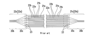
- the electrode body 20 is formed by winding the positive electrode plate 21, the negative electrode plate 22, and the separator 23. At this time, by shifting the positive electrode plate 21 and the negative electrode plate 22 left and right in the width direction, the positive electrode active material layer non-forming portion is formed from the side end of the negative electrode plate 23 on one end side of the electrode body 20 as shown in FIG. 21c protrudes in the laminated state, and on the other end side of the electrode body 20, the negative electrode active material layer non-forming portion 22c protrudes from the side end of the positive electrode plate 21 in the laminated state.
- the electrode body 20 has a positive projection 20a on one end side and a negative projection 20a on the other end.
- the positive protrusions 20a are brought into close contact with each other in a stage before being joined to the current collector 40, so that the constraining part formed by bundling the leading ends of the protrusions 20a. 20b and an inclined portion 20c that is inclined from the proximal end side of the protruding portion 20a toward the restricting portion 20b.
- the protruding portion 20a of the negative electrode of the electrode body 20 is also brought into close contact with each other in the stage before being joined to the current collector 40, whereby a restraining portion 20b formed by bundling the tip side of the protruding portion 20a, And an inclined portion 20c that is inclined from the proximal end side of the protruding portion 20a toward the restricting portion 20b.
- a positive electrode current collector 40 made of, for example, aluminum or an aluminum alloy is disposed on one surface of the constraining portion 20b of the protruding portion 20a of the positive electrode, and aluminum or aluminum is also formed on the other surface of the constraining portion 20b.
- An abutting plate 50 made of an alloy is disposed. The current collector 40 and the contact plate 50 are bonded together with the restraining portion 20b by, for example, ultrasonic bonding.
- a negative electrode current collector 40 made of, for example, copper or a copper alloy is disposed on one surface of the constraining portion 20b of the protruding portion 20a of the negative electrode, and a contact plate 50 also made of copper or a copper alloy is disposed on the other surface of the constraining portion 20b. Is arranged.
- the current collector 40 and the contact plate 50 are bonded together with the restraining portion 20b by, for example, ultrasonic bonding.
- the positive electrode active material layer 21b is not formed on the positive electrode current collector base 21a, or the negative electrode active material layer 22b is not formed on the negative electrode current collector base 22a. Therefore, a gap is formed between the adjacent positive electrode active material layer non-forming portions 21c and 21c, or a gap is formed between the adjacent negative electrode active material layer non-forming portions 22c and 22c. Therefore, the inclined portion 20c is relatively easily compressed and deformed with respect to the force received from the restraining portion 20b.
- the electrode body 20 vibrates with an amplitude or frequency different from that of the current collector 40, and the edge of the contact plate 50 is rubbed against the inclined portion 20c.
- the inclined portion 20c may be damaged by hitting.
- the current collecting function is lowered, and problems such as an increase in the internal resistance of the battery are likely to occur.
- an object of the present invention is to provide a power storage device that can suitably prevent the end portion of the electrode body from being damaged by vibration.
- the electricity storage device is: An electrode body in which a positive electrode plate and a negative electrode plate are laminated, and the electrode body has a protruding portion in which at least one of the positive electrode plate and the negative electrode plate protrudes in a laminated state,
- the projecting portion includes a restraint portion formed by bundling the distal end side of the projecting portion, and an electrode body having an inclined portion that slopes from the base end side of the projecting portion toward the restraint portion;
- a contact member disposed to face at least one of the surfaces of the restraint portion and the other surface;
- a current collector having a connection piece disposed to face at least the other surface of both surfaces of the restraint portion and the other surface;
- the abutting member has a base portion along the surface of the restraining portion and a skirt portion extending from the base portion to the base end side of
- the skirt portion of the abutting member extends from the base portion to the base end side of the protruding portion along the surface of the inclined portion. Therefore, a situation in which the inclined portion is damaged due to the edge of the abutting member being rubbed or hitting the inclined portion does not occur.
- the abutting member may further include a reinforcing piece connected to the base portion and the skirt portion.
- the rigidity of the skirt portion relative to the base portion can be increased, and the strength of the abutting member can be improved.
- the restraining portion is formed in a partial region of the protruding portion in the second direction intersecting the first direction in which the protruding portion protrudes.
- the protruding portion has a second inclined portion that is inclined toward the restraining portion in the second direction,
- the reinforcing piece may be provided at the end of the abutting member and be along the surface of the second inclined portion.
- the reinforcing piece of the contact member extends along the surface of the second inclined portion from the end portion of the contact member. Therefore, even if relative displacement occurs between the abutting member and the protruding portion due to vibration in the second direction, the edge of the reinforcing piece of the abutting member rubs against or strikes the second inclined portion. The situation that the inclined part is damaged does not occur. Moreover, the wide range of the 2nd inclination part with weak mechanical strength can be supported by the reinforcement piece of a contact member. For this reason, wrinkles do not approach the second inclined portion due to vibration or the like, and damage to the second inclined portion due to wrinkles is less likely to occur. That is, the reinforcing piece forms a skirt portion in the second direction.
- the abutting member can have a base portion and a skirt portion on the other surface side of both surfaces of the restraint portion and the other surface.
- the contact member has a clip shape. That is, the protruding portion of the electrode body is constrained by the pair of base portions of the contact member and the pair of skirt portions. For this reason, on both the one surface and the other surface of the inclined portion, there is no situation in which the inclined portion is damaged due to the edge of the contact member being rubbed or hitting the inclined portion.
- the projecting portion includes a first projecting portion and a second projecting portion facing the first projecting portion with an interval
- the abutting member includes a first abutting member disposed on the outer surface of the first protrusion, and a second abutting member disposed on the outer surface of the second protrusion
- the first abutting member also has a base portion and a skirt portion on the inner surface side of the first protruding portion
- the second contact member may have a base portion and a skirt portion on the inner surface side of the second protrusion.
- both the first abutting member and the second abutting member have a clip shape. That is, the first projecting portion is restrained by the pair of base portions of the first abutting member and the pair of skirt portions, and the second projecting portion is composed of the pair of base portions of the second abutting member and the pair of skirts. It is restrained by the part. For this reason, in each of the outer surface and the inner surface of the inclined portion, a situation in which the inclined portion is damaged due to the edge of the abutting member being rubbed or hitting the inclined portion does not occur.
- the tip of the skirt part located in the 2nd contact member side among the skirt parts of the 1st contact member, and the tip of the skirt part located in the 1st contact member side among the skirt parts of the 2nd contact member Can be linked to each other.
- the first contact member and the second contact member are integrated, and not only the strength as the contact member can be increased, but also the protruding portions (first and second protrusions) of the electrode body. Part) can be increased in bonding strength of the abutting member.
- the projecting portion includes a first projecting portion and a second projecting portion facing the first projecting portion with an interval
- the abutting member can include a first abutting member disposed on the inner surface of the first projecting portion and a second abutting member disposed on the inner surface of the second projecting portion.
- the inner surface of the inclined portion in the first projecting portion is protected by the skirt portion of the first abutting member, and the inner surface of the inclined portion in the second projecting portion is protected by the skirt portion of the second abutting member. Is done.
- the tip of the skirt portion of the first abutting member and the tip of the skirt portion of the second abutting member can be connected.
- the first contact member and the second contact member are integrated, and not only the strength as the contact member can be increased, but also the protruding portions (first and second protrusions) of the electrode body. Part) can be increased in bonding strength of the abutting member.
- the abutting member further includes a connecting piece that couples the side edge of the first abutting member and the side edge of the second abutting member in the second direction intersecting the first direction in which the protruding portion projects. Can do.
- the contact member since the contact member has a three-dimensional structure, high mechanical strength can be realized. Accordingly, when the contact member is formed by, for example, forming a plate material, the weight can be reduced by using a thin plate material.
- the connecting piece can be configured to block a side opening portion constituted by the side edge of the first contact member and the side edge of the second contact member.
- the contact member is cup-shaped, high mechanical strength can be realized. Accordingly, when the contact member is formed by, for example, forming a plate material, the weight can be reduced by using a thin plate material.
- the electrode plate includes a current collecting base material and an active material layer formed on the surface excluding one end of the current collecting base material, One end portion of the current collecting base material is an active material layer non-formation portion in which an active material layer is not formed,
- the protruding portion can be formed by the active material layer non-forming portion.
- a gap is likely to be formed between adjacent portions where the active material layer is not formed in the inclined portion of the protruding portion. For this reason, the inclined portion is relatively easily compressed and deformed with respect to the force received from the restraining portion.
- the above-described configuration of the abutting member can suitably prevent the inclined portion from being damaged.
- the electrode body is a flat electrode body wound in a state where the positive electrode plate and the negative electrode plate are insulated from each other, the pair of folded portions facing each other with the winding center axis interposed therebetween, and the pair of folded portions
- the contact member may be disposed on the outer surface of the end portion of the electrode body so that the reinforcing piece is along the outer surface of the second inclined portion.
- the reinforcing piece of the contact member extends along the surface of the second inclined portion from the end portion of the contact member. Therefore, even if relative displacement occurs between the abutting member and the protruding portion due to vibration in the second direction, the edge of the reinforcing piece of the abutting member rubs against or strikes the second inclined portion. The situation that the inclined part is damaged does not occur. Moreover, the wide range of the 2nd inclination part with weak mechanical strength can be supported by the reinforcement piece of a contact member. For this reason, wrinkles do not approach the second inclined portion due to vibration or the like, and damage to the second inclined portion due to wrinkles is less likely to occur. That is, the reinforcing piece forms a skirt portion in the second direction.
- the skirt portion can extend to the base end of the protrusion.
- the inclined portion having the weakest mechanical strength can be supported by the entire skirt portion of the abutting member. For this reason, wrinkles do not approach the inclined portion due to vibration or the like, and damage to the inclined portion due to wrinkles is less likely to occur.
- the electricity storage device of the present invention it is possible to suitably prevent the end portion of the electrode body from being damaged by vibration. For this reason, it is possible to suitably prevent the current collecting function from being deteriorated and the internal resistance of the battery from being increased due to damage to the end of the electrode body.
- FIG. 1 shows a partially broken front view of the battery according to the first embodiment.
- FIG. 2 is a perspective view of the structure in the case of the battery.
- FIG. 3A shows a front view of a current collector in the battery.
- FIG. 3B shows a side view of the current collector in the battery.
- FIG. 3C shows a perspective view of a current collector in the battery.
- FIG. 4A shows a perspective view of the battery seen from one side of the contact member.
- FIG. 4B shows a perspective view of the battery as viewed from the opposite side of the contact member.
- FIG. 4C shows a cross-sectional view of the contact member in FIG.
- FIG. 5 is a sectional view taken along line AA in FIG. 6 shows a cross-sectional view taken along the line BB of FIG.
- FIG. 5 is a sectional view taken along line AA in FIG. 6 shows a cross-sectional view taken along the line BB of FIG.
- FIG. 5 is a sectional view taken
- FIG. 7A shows a cross-sectional view taken along the line BB of FIG. 1 in a state before a partial region of the electrode body is bundled.
- FIG. 7B shows a cross-sectional view taken along line BB of FIG. 1 in a state where a part of the electrode body is bundled.
- FIG. 7C shows a cross-sectional view taken along line BB of FIG. 1 in a state where a current collector is joined to a partial region of the electrode body.
- FIG. 8 shows a partially broken front view of the battery according to the second embodiment.
- FIG. 9 shows a perspective view of the structure in the case of the battery.
- FIG. 10A shows a front view of a current collector in the battery.
- FIG. 10B shows a side view of the current collector in the battery.
- FIG. 10A shows a front view of a current collector in the battery.
- FIG. 10C shows a perspective view of a current collector in the battery.
- FIG. 11A shows a perspective view seen from one side of the contact member in the battery.
- FIG. 11B shows a perspective view of the battery as viewed from the opposite side of the contact member.
- FIG. 11C shows a cross-sectional view of the contact member in the battery taken along line FF of FIG. 11A.
- FIG. 12 is a sectional view taken along line DD of FIG.
- FIG. 13 is a sectional view taken along line EE of FIG.
- FIG. 14A shows various modifications.
- FIG. 14B shows various modifications.
- FIG. 14C shows various modifications.
- FIG. 14D shows various modifications.
- FIG. 15A shows an explanatory diagram for explaining each element of a positive electrode plate constituting a general electrode body.
- FIG. 15A shows an explanatory diagram for explaining each element of a positive electrode plate constituting a general electrode body.
- FIG. 15A shows an explanatory diagram for explaining each element of
- FIG. 15B shows an explanatory diagram for explaining each element of the negative electrode plate constituting the electrode body.
- FIG. 15C is an explanatory diagram for explaining the arrangement relationship in the width direction of a positive electrode plate, a negative electrode plate, and a separator in a general electrode body.
- FIG. 16A shows a cross-sectional view of the electrode body.
- FIG. 16B shows a cross-sectional view in a state where the ends of the electrode body are bundled.
- FIG. 16C shows a cross-sectional view of a state in which a current collector is joined to the end of the electrode body.
- the battery according to the first embodiment includes a metal case 10, an electrode body 20 accommodated in the case 10, and a positive electrode terminal protruding outward from the inside of the case 10. 31 and the negative electrode terminal 32, the current collector 40 connecting the end of the electrode body 20 and the electrode terminals 31, 32, and the contact connected to the end of the electrode body 20 in cooperation with the current collector 40
- the member 50 is provided.
- the case 10 is a combination of a bottomed rectangular tube-shaped case main body 11 having an opening and a lid 12 that closes the opening of the case main body 11. After assembling both 11 and 12, the edge of the opening part of case body 11 and the outer periphery of lid 12 are welded, and both 11 and 12 are united.
- the case main body 11 has a pair of opposing side plate portions 11b and a pair of opposing end plate portions 11c erected on the periphery of the rectangular bottom portion 11a.
- the case main body 11 is formed in a thin bottomed rectangular tube shape with a small depth by making the pair of end plate portions 11c narrower (than the pair of side plate portions 11b).
- the lid 12 is formed with holes (not numbered) through which the electrode terminals 31 and 32 pass.
- the electrode terminals 31 and 32 penetrate the hole of the lid body 12 and are fixed to the lid body 12 like rivets. Therefore, the outer ends of the electrode terminals 31 and 32 protrude from the lid body 12, and the inner ends of the electrode terminals 31 and 32 protrude into the case 10.
- the electrode body 20 has the same configuration as the conventional one. Therefore, the description of the electrode body 20 in the background art section can be used as the description of the electrode body 20.
- the electrode body 20 is arranged in the case 10 so that its axis is parallel to the bottom portion 11a of the case 10, that is, the pair of projecting portions 20a and 20a are opposed to the end plate portions 11c of the case 10, respectively. Is housed in.
- the current collector 40 includes a positive electrode current collector 40 that connects the positive electrode protrusion 20 a of the electrode body 20 and the positive electrode terminal 31, and a negative electrode protrusion 20 a and a negative electrode terminal 32 of the electrode body 20. There is a negative electrode current collector 40 to be connected.
- the current collector 40 is formed by connecting the positive electrode terminal 31 or the negative electrode terminal 32 by caulking like a rivet or connecting the electrode terminals 31 and 32 by welding and the electrode body 20.
- the electrode attachment portion 42 connected directly or indirectly to the restraint portion 20b in the positive electrode protrusion portion 20a or the restraint portion 20b in the negative electrode protrusion portion 20a, and the internal connection portion 41 and the electrode attachment portion 42 are connected. And an intermediate portion 43.
- the current collector 40 is formed of a single metal material into a deformed L shape when viewed from the front.
- the positive electrode current collector 40 is made of, for example, aluminum or an aluminum alloy, and the negative electrode current collector 40 is made of, for example, copper or a copper alloy.
- the internal connection portion 41 and the electrode attachment portion 42 are oriented in a right angle direction (L shape in front view) with the intermediate portion 43 as a fold.
- the internal connection portion 41 is disposed along the back surface of the lid body 12 of the case 10 while being insulated from the back surface of the lid body 12 of the case 10.
- a through hole 41 a into which the inner end portion of the positive electrode terminal 31 or the negative electrode terminal 32 is fitted is provided at the distal end portion of the internal connection portion 41.
- the electrode attachment portion 42 is disposed between the end portion of the electrode body 20 and the end plate portion 11 c of the case body 11.
- the electrode attachment portion 42 includes an opening 42a as shown in FIGS. 3A to 3C.
- Two connection pieces 42b and 42b are provided protruding from both edges of the opening 42a in the same direction as the internal connection portion 41.
- the opening 42a and the connecting pieces 42b and 42b are formed by, for example, making a cut in the length direction in the state of the strip before forming the electrode attachment portion 42 and raising both sides of the cut.
- the contact member 50 has a base portion 50a along the outer surface of the restraining portion 20b at the end of the electrode body 20 (the surface on the side far from the winding center axis of both surfaces of the restraining portion 20b). And a skirt portion 50b extending from the base portion 50a along the surface of the inclined portion 20c to the base end B1 of the protruding portion 20a or the vicinity of the base end B1. Further, the abutting member 50 is connected to the folded portion 50c folded from the base portion 50a, and the inner surface of the restraint portion 20b at the end of the electrode body 20 (the winding center of both surfaces of the restraint portion 20b). A base portion 50d along the surface near the axis) and a skirt portion 50e extending from the base portion 50d along the surface of the inclined portion 20c to the base end B2 of the projecting portion 20a or the vicinity of the base end B2. .
- the contact member 50 includes a positive electrode contact member 50 connected to the positive electrode protrusion 20 a of the electrode body 20 and a negative electrode contact member 50 connected to the negative electrode protrusion 20 a of the electrode body 20.
- a pair of protruding portions 20a of the electrode body 20 is formed in both the positive electrode and the negative electrode. That is, the protruding portion 20a of the electrode body 20 includes a first protruding portion 20aA and a second protruding portion 20aB that is opposed to the first protruding portion 20aA with a gap.
- the abutting member 50 includes a first abutting member 50A for the first projecting portion 20aA and a second abutting member 50B for the second projecting portion 20aB.
- the positive electrode contact member 50 is formed of, for example, aluminum or an aluminum alloy, as in the positive electrode current collector 40, and the negative electrode contact member 50 is formed of, for example, copper or a copper alloy, as in the negative electrode current collector 40. Yes. Each of them is formed by press-molding a plate material. Accordingly, the abutting member 50 is a plate material in which the skirt portion 50b, the base portion 50a, the folded portion 50c, the base portion 50d, and the skirt portion 50e are continuously connected.
- the abutting member 50 has reinforcing pieces 50f connected to the base portion 50a and the skirt portion 50b at both ends of the abutting member 50.
- the restraining portion 20b of the protruding portion 20a of the electrode body 20 is formed in a partial region of the protruding portion 20a in the second direction Y intersecting the first direction X in which the protruding portion 20a protrudes.
- the protrusion part 20a has the 2nd inclination part 20d inclined in the 2nd direction Y toward the restraint part 20b.
- the electrode body 20 has a flat shape in which the positive electrode plate 21 and the negative electrode plate 22 are wound in a state of being insulated from each other, so that a pair of semicircular arcs facing each other with the winding center axis therebetween.
- the folded portions 20e and 20e and a flat portion 20f positioned between the pair of folded portions 20e and 20e.
- the restraining part 20b is formed in the flat part 20f.
- the reinforcing piece 50f extends in the second direction Y while being gently inclined along the surface of the second inclined portion 20d.
- a reinforcing piece 50g is also formed at the ends of the base 50d and the skirt 50e.
- connection pieces 42b and 42b of the current collector 40 are inserted into the space between the first protrusion 20aA and the second protrusion 20aB, and one connection piece 42b is
- the base 50d of the first abutting member 50A is disposed along the other connecting piece 42b and the base 50d of the second abutting member 50B is disposed along the base 50d.
- the anvil is applied to the connection piece 42b, and the ultrasonic vibrator is applied to the base 50a of the contact member 50.
- the ultrasonic vibrator is vibrated ultrasonically, frictional heat is generated, and the connecting piece 42b and the contact member 50 are ultrasonically bonded together with the restraining portion 20b.
- the current collector 40 includes a positive current collector 40 that connects the positive electrode protrusion 20a of the electrode body 20 and the positive electrode terminal 31, and a negative electrode protrusion of the electrode body 20. 20a and a negative electrode current collector 40 that connects the negative electrode terminal 32 to each other.
- the current collector 40 is formed by connecting the positive electrode terminal 31 or the negative electrode terminal 32 by caulking like a rivet or connecting the electrode terminals 31 and 32 by welding and the electrode body 20.
- the electrode attachment portion 42 connected directly or indirectly to the restraint portion 20b in the positive electrode protrusion portion 20a or the restraint portion 20b in the negative electrode protrusion portion 20a, and the internal connection portion 41 and the electrode attachment portion 42 are connected. And an intermediate portion 43.
- the current collector 40 is formed of a single metal material into a deformed L shape when viewed from the front.
- the positive electrode current collector 40 is made of, for example, aluminum or an aluminum alloy, and the negative electrode current collector 40 is made of, for example, copper or a copper alloy.
- the internal connection portion 41 and the electrode attachment portion 42 are oriented in a right angle direction (L shape in front view) with the intermediate portion 43 as a fold.
- the internal connection portion 41 is disposed along the back surface of the lid body 12 of the case 10 while being insulated from the back surface of the lid body 12 of the case 10.
- a through hole 41 a into which the inner end portion of the positive electrode terminal 31 or the negative electrode terminal 32 is fitted is provided at the distal end portion of the internal connection portion 41.
- the electrode attachment portion 42 has a pair of bifurcated connection pieces 42 b and 42 b arranged in the same direction as the internal connection portion 41.
- the contact member 50 includes a base portion 50a along the inner surface of the restraint portion 20b at the end of the electrode body 20 (the surface on the side closer to the winding center axis of both surfaces of the restraint portion 20b). And a skirt portion 50b extending from the base portion 50a along the surface of the inclined portion 20c to the base end B2 of the protruding portion 20a or the vicinity of the base end B2.
- the base 50a is formed on the base 50a along the inner surface of the restraining portion 20b in the first projecting portion 20aA and the inner surface of the restraining portion 20b in the second projecting portion 20aB facing the first projecting portion 20aA with a gap.
- the skirt portion 50b includes a skirt portion 50b along the inner surface of the inclined portion 20c in the first protruding portion 20aA and a skirt portion 50b along the inner surface of the inclined portion 20c in the second protruding portion 20aB. Therefore, the base 50a and the skirt 50b for the first protrusion 20aA correspond to the first abutting member 50A, and the base 50a and the skirt 50b for the second protrusion 20aB correspond to the second abutting member 50B. To do.
- the tip of the skirt portion 50b of the first abutting member 50A and the tip of the skirt portion 50b of the second abutting member 50B are connected. Further, the side edge of the first abutting member 50A and the side edge of the second abutting member 50B are connected by a connecting piece 50h, and are constituted by the first abutting member 50A and the second abutting member 50B. The side opening is closed by the connecting piece 50h. Thereby, 50 A of 1st contact members and the 2nd contact member 50B are integrated, and are formed in the cup shape.
- the contact member 50 includes a positive contact member 50 connected to the positive protrusion 20a of the electrode body 20 and a negative contact member 50 connected to the negative protrusion 20a of the electrode body 20.
- the positive electrode contact member 50 is formed of, for example, aluminum or an aluminum alloy, as in the positive electrode current collector 40
- the negative electrode contact member 50 is formed of, for example, copper or a copper alloy, as in the negative electrode current collector 40. Yes. Each of them is formed by press-molding a plate material. Therefore, the abutting member 50 is a plate material in which a pair of base portions 50a and 50a, a pair of skirt portions 50b and 50b, and a pair of connecting pieces 50h and 50h are continuously connected.
- the first protrusion 20aA and the second protrusion 20aB are inserted between the pair of connection pieces 42b and 42b of the current collector 40, and one connection piece 42b is the first connection piece 42b.
- the other connecting piece 42b is placed along the outer surface of the restraining portion 20b in the second projecting portion 20aB along the outer surface of the restraining portion 20b in the projecting portion 20aA.
- the anvil is applied to the connection piece 42b, and the ultrasonic vibrator is applied to the base 50a of the contact member 50. Then, when the ultrasonic vibrator is vibrated ultrasonically, frictional heat is generated, and the connecting piece 42b and the contact member 50 are ultrasonically bonded together with the restraining portion 20b.
- the positive electrode plate 21 and the negative electrode plate 22 are stacked, and the electrode body 20 includes both the positive electrode plate 21 and the negative electrode plate 22.
- At least one of the electrode plates has a protruding portion 20a protruding in a stacked state, and the protruding portion 20a includes a restraining portion 20b formed by bundling the distal end side of the protruding portion 20a, and a protruding portion 20a.
- the electrode body 20 having an inclined portion 20c that is inclined from the base end B1 side toward the restricting portion 20b is disposed to face at least one of the two surfaces of the one surface and the other surface of the restricting portion 20b.
- the electrode body 20 is supported by the current collector 40 in the case 10, and the abutting member 50 includes a base portion 50a along the surface of the restraining portion 20b, and an inclined portion 20c from the base portion 50a. And a skirt portion 50b extending to the base end B1 side of the protruding portion 20a.
- the skirt part 50b of the contact member 50 is extended from the base part 50a to the base end side of the protrusion part 20a along the surface of the inclination part 20c. Therefore, a situation in which the inclined portion 20c is damaged due to the edge of the abutting member 50 being rubbed or hitting the inclined portion 20c does not occur.
- the abutting member 50 further includes the reinforcing piece 50f connected to the base 50a and the skirt 50b.
- the rigidity of the skirt part 50b with respect to the base part 50a can be improved, and the intensity
- the restraining portion 20b is formed in a partial region of the protruding portion 20a in the second direction Y intersecting the first direction X in which the protruding portion 20a protrudes.
- the protruding portion 20a has a second inclined portion 20d inclined in the second direction Y toward the restricting portion 20b, and the reinforcing piece 50g is provided at an end portion of the abutting member 50, and the second inclined portion.
- the reinforcing piece 50g of the abutting member 50 extends from the end of the abutting member 50 along the surface of the second inclined portion 20d.
- the edge of the reinforcing piece 50g of the abutting member 50 is rubbed or hits the second inclined portion 20d.
- the situation that the second inclined portion 20d is damaged does not occur.
- a wide range of the second inclined portion 20 d having a low mechanical strength can be supported by the reinforcing piece 50 g of the contact member 50.
- the second inclined portion 20d is prevented from wrinkling due to vibration or the like, and the second inclined portion 20d is not easily damaged due to wrinkles. That is, the reinforcing piece 50g forms a skirt portion in the second direction Y.
- the contact member 50 has the base part 50d and the skirt part 50e also on the other surface side of both surfaces of one side and the other side of the restraint part 20b.
- the contact member 50 has a clip shape. That is, the protruding portion 20a of the electrode body 20 is constrained by the pair of base portions 50a and 50d of the abutting member 50 and the pair of skirt portions 20b and 50e. Therefore, the situation that the inclined part 20c is damaged by the edge of the contact member 50 being rubbed against or hitting the inclined part 20c on both the one surface and the other surface of the inclined part 20c does not occur.
- the protruding portion 20a includes the first protruding portion 20aA and the second protruding portion 20aB that is opposed to the first protruding portion 20aA with an interval.
- the abutting member 50 includes a first abutting member 50A disposed on the outer surface of the first projecting portion 20aA and a second abutting member 50B disposed on the outer surface of the second projecting portion 20aB.
- the first abutting member 50A has a base portion 50d and a skirt portion 50e on the inner surface side of the first projecting portion 20aA
- the second abutting member 50B is disposed on the inner surface side of the second projecting portion 20aB.
- both the first contact member 50A and the second contact member 50B have a clip shape. That is, the first projecting portion 20aA is restrained by the pair of base portions 50a and 50d and the pair of skirt portions 50b and 50e of the first abutting member 50A, and the second projecting portion 20aB is the second abutting member.
- the pair of base portions 50a and 50d of 50B and the pair of skirt portions 50b and 50e are restrained. Therefore, in each of the outer surface and the inner surface of the inclined portion 20c, a situation in which the inclined portion 20c is damaged due to the edge of the contact member 50 being rubbed or hitting the inclined portion 20c does not occur.
- the tip of the skirt part 50e located on the second abutting member 50B side of the skirt parts 50b, 50e of the first abutting member 50A, and the second abutting member Of the skirt portions 50b and 50e of 50B, the tip of the skirt portion 50e located on the first abutting member 50A side is connected.
- the first abutting member 50A and the second abutting member 50B are integrated and not only the strength as the abutting member 50 can be increased, but also the protruding portion 20a (first and second) of the electrode body 20 , The bonding strength of the abutting member 50 to the protrusions 20aA, 20aB) can be increased.
- the protruding portion 20a includes the first protruding portion 20aA and the second protruding portion 20aB that is opposed to the first protruding portion 20aA with an interval.
- the abutting member 50 includes a first abutting member 50A disposed on the inner surface of the first protrusion 20aA and a second abutting member 50B disposed on the inner surface of the second protrusion 20aB. .
- the inner surface of the inclined portion 20c in the first protruding portion 20aA is protected by the skirt portion 50e of the first abutting member 50A, and the inner surface of the inclined portion 20c in the second protruding portion 20aB is the second abutting member 50B. It is protected by the skirt 50e.
- the tip of the skirt portion 50e of the first contact member 50A and the tip of the skirt portion 50e of the second contact member 50B are connected.
- the first abutting member 50A and the second abutting member 50B are integrated and not only the strength as the abutting member 50 can be increased, but also the protruding portion 20a (first and second) of the electrode body 20 , The bonding strength of the abutting member 50 to the protrusions 20aA, 20aB) can be increased.
- the abutting member 50 includes the side edge of the first abutting member 50A and the second edge in the second direction Y that intersects the first direction X in which the projecting portion 20a projects. It further has a connecting piece 50h that connects the side edge of the abutting member 50B.
- the connecting piece 50h closes the side opening portion constituted by the side edge of the first contact member 50A and the side edge of the second contact member 50B.
- an electrode plate is the active material formed in the surface except the current collection base materials 21a and 22a and the one end part of this current collection base materials 21a and 22a.
- the active material layer non-formation parts 21c and 22c in which the active material layers 21b and 22b are not formed are included in the current collector base materials 21a and 22a. It is formed by the layer non-formation parts 21c and 22c.
- the electrode body 20 is a flat electrode body 20 wound in a state where the positive electrode plate 21 and the negative electrode plate 22 are insulated from each other,
- the electrode body 20 includes a pair of folded portions 20e and 20e facing each other across the winding center axis, and a flat portion 20f positioned between the pair of folded portions 20e and 20e, and the protruding portion 20a has a winding center.
- the restraining portion 20b is formed at the flat portion 20f of the end of the electrode body 20, and the second inclined portion 20d is formed at the end of the electrode body 20.
- the abutting member 50 is disposed on the outer surface of the end portion of the electrode body 20, and the reinforcing piece 50g is along the outer surface of the second inclined portion 20d.
- the reinforcing piece 50g of the abutting member 50 extends from the end of the abutting member 50 along the surface of the second inclined portion 20d. Therefore, in the second direction Y, even if a relative displacement occurs between the abutting member 50 and the protruding portion 20a due to vibration, the edge of the reinforcing piece 50g of the abutting member 50 is rubbed or hits the second inclined portion 20d. Thus, the situation that the second inclined portion 20d is damaged does not occur.
- the second inclined portion 20 d having a low mechanical strength can be supported by the reinforcing piece 50 g of the contact member 50. For this reason, the second inclined portion 20d is prevented from wrinkling due to vibration or the like, and the second inclined portion 20d is not easily damaged due to wrinkles. That is, the reinforcing piece 50g forms a skirt portion in the second direction Y.
- the skirt portions 50b and 50e extend to the base ends B1 and B2 of the protruding portion 20a. Accordingly, the inclined portion 20c having the weakest mechanical strength can be supported by the entire skirt portions 50b and 50e of the contact member 50. Therefore, wrinkles do not approach the inclined portion 20c due to vibration or the like, and damage to the inclined portions due to wrinkles is less likely to occur.
- the wound electrode body 20 in which the long positive electrode plate 21, the negative electrode plate 22, and the separator 23 are wound is employed.
- the electrode body may be a laminate of a plurality of positive plates, negative plates and separators. Since the wound electrode body 20 has the folded portion (semicircular arc portion) 20e as described above, the constraining portion 20b cannot be formed in the entire length of the electrode body 20 in the second direction. However, in the stacked electrode body, the restraining portion and the inclined portion can be formed over the entire length in the second direction of the electrode body.
- the wound electrode body 20 such as providing a restraining portion and an inclined portion in the middle portion of the electrode body in the second direction, or providing a restraining portion and an inclined portion in the end portion of the electrode body in the second direction, etc. You may make it provide a restraint part and an inclination part partially in a 2nd direction.
- the contact member 50 is applied to both the positive electrode protrusion 20a and the negative electrode protrusion 20a. However, it may be applied to only one of them.
- the abutting member can be appropriately selected from various forms without departing from the gist of the present invention.
- the tip of the skirt portion 50e located on the second abutting member 50B side of the pair of skirt portions 50b and 50e of the first abutting member 50A, and the second Of the pair of skirt portions 50b, 50e of the contact member 50B, the tip of the skirt portion 50e located on the first contact member 50A side is connected, and the first and second contact members 50A, 50B are integrated. May be.
- connection piece 42b of the current collector 40 is directly along the inner surface of the restraining portion 20b.
- the pair of skirt portions 50b and 50b may be divided.
- the first contact member 50A and the second contact member 50B are separated.
- a wraparound portion to the outer surface side of the protruding portion 20a which is configured by the folded portion 50c, the base portion 50d, and the skirt portion 50e, may be provided.
- the connecting piece 42b of the current collector 40 is indirectly along the outer surface of the restricting portion 20b via the base portion 50d.
- the abutting member 50 is formed of a plate material. However, it is not limited to this.
- the contact member may be in a block shape, for example.
- reinforcing pieces 50f and 50f are provided at both ends of the abutting member 50.
- the reinforcing piece 50f may be provided only at one of the ends. Further, the reinforcing piece 50f is not necessarily formed at the end of the abutting member 50. As long as the strength of the skirt portion 50b with respect to the base portion 50a can be ensured, the place where the reinforcing piece 50f is formed does not matter.
- the reinforcing piece 50g is the same as the reinforcing piece 50f.
- the reinforcing piece 50f is provided at the end of the abutting member 50 in that not only the reinforcement of the skirt portion 50b with respect to the base portion 50a but also the protection against the second inclined portion 20d can be realized as described above. Is preferred.
- the contact member 50 is formed in a cup shape by press molding a plate material.
- the contact member 50 may be formed in a cup shape by bending or welding a plate material in which the three-dimensional shape is developed in a plane.
- connection piece 42b of the current collector 40 and the contact member 50 are ultrasonically bonded.
- the joining method can be performed by various means such as resistance welding, laser welding, and caulking in addition to ultrasonic joining.
- the lithium ion secondary battery has been described.
- the type and size (capacity) of the battery are arbitrary.
- the present invention is not limited to the lithium ion secondary battery.
- the present invention can also be applied to various secondary batteries, other primary batteries, and capacitors such as electric double layer capacitors.
Abstract
Description
正極板と負極板とが積層された電極体であって、該電極体は、正極板及び負極板の両電極板のうちの少なくとも一方の電極板が積層状態で突出した突出部を有し、該突出部は、該突出部の先端側を束ねて形成された拘束部と、突出部の基端側から拘束部に向かって傾斜する傾斜部とを有する、電極体と、
拘束部の一面及び他面の両表面のうちの少なくとも一方の表面に対向して配置される当て部材と、
拘束部の一面及び他面の両表面のうちの少なくとも他方の表面に対向して配置される接続片を有する集電体と、
電極体、当て部材及び集電体を収容するケースであって、該ケース内で電極体が集電体によって支持される、ケースとを備え、
当て部材は、拘束部の表面に沿う基部と、該基部から傾斜部の表面に沿って突出部の基端側に延びるスカート部とを有する。 The electricity storage device according to the present invention is:
An electrode body in which a positive electrode plate and a negative electrode plate are laminated, and the electrode body has a protruding portion in which at least one of the positive electrode plate and the negative electrode plate protrudes in a laminated state, The projecting portion includes a restraint portion formed by bundling the distal end side of the projecting portion, and an electrode body having an inclined portion that slopes from the base end side of the projecting portion toward the restraint portion;
A contact member disposed to face at least one of the surfaces of the restraint portion and the other surface;
A current collector having a connection piece disposed to face at least the other surface of both surfaces of the restraint portion and the other surface;
A case containing an electrode body, a contact member and a current collector, wherein the electrode body is supported by the current collector in the case, and
The abutting member has a base portion along the surface of the restraining portion and a skirt portion extending from the base portion to the base end side of the protruding portion along the surface of the inclined portion.
当て部材は、基部とスカート部とに連結される補強片をさらに有する
ようにすることができる。 Here, as one aspect of the electricity storage device according to the present invention,
The abutting member may further include a reinforcing piece connected to the base portion and the skirt portion.
拘束部は、突出部が突出する第1方向と交差する第2方向において、突出部の一部領域に形成され、
突出部は、第2方向において、拘束部に向かって傾斜する第2の傾斜部を有し、
補強片は、当て部材の端部に設けられ、第2の傾斜部の表面に沿っている
ようにすることができる。 in this case,
The restraining portion is formed in a partial region of the protruding portion in the second direction intersecting the first direction in which the protruding portion protrudes.
The protruding portion has a second inclined portion that is inclined toward the restraining portion in the second direction,
The reinforcing piece may be provided at the end of the abutting member and be along the surface of the second inclined portion.
当て部材は、拘束部の一面及び他面の両表面のうちの他方の表面側にも、基部とスカート部とを有する
ようにすることができる。 Further, as another aspect of the electricity storage device according to the present invention,
The abutting member can have a base portion and a skirt portion on the other surface side of both surfaces of the restraint portion and the other surface.
突出部は、第1の突出部と、該第1の突出部と間隔を有して対向する第2の突出部とを含み、
当て部材は、第1の突出部の外面に配置される第1の当て部材と、第2の突出部の外面に配置される第2の当て部材とを含み、
第1の当て部材は、第1の突出部の内面側にも、基部とスカート部とを有し、
第2の当て部材は、第2の突出部の内面側にも、基部とスカート部とを有する
ようにすることができる。 Moreover, as another aspect of the electrical storage element which concerns on this invention,
The projecting portion includes a first projecting portion and a second projecting portion facing the first projecting portion with an interval,
The abutting member includes a first abutting member disposed on the outer surface of the first protrusion, and a second abutting member disposed on the outer surface of the second protrusion,
The first abutting member also has a base portion and a skirt portion on the inner surface side of the first protruding portion,
The second contact member may have a base portion and a skirt portion on the inner surface side of the second protrusion.
第1の当て部材のスカート部のうちの第2の当て部材側に位置するスカート部の先端と、第2の当て部材のスカート部のうちの第1の当て部材側に位置するスカート部の先端とが連結されている
ようにすることができる。 in this case,
The tip of the skirt part located in the 2nd contact member side among the skirt parts of the 1st contact member, and the tip of the skirt part located in the 1st contact member side among the skirt parts of the 2nd contact member Can be linked to each other.
突出部は、第1の突出部と、該第1の突出部と間隔を有して対向する第2の突出部とを含み、
当て部材は、第1の突出部の内面に配置される第1の当て部材と、第2の突出部の内面に配置される第2の当て部材とを含む
ようにすることができる。 As still another aspect of the electricity storage device according to the present invention,
The projecting portion includes a first projecting portion and a second projecting portion facing the first projecting portion with an interval,
The abutting member can include a first abutting member disposed on the inner surface of the first projecting portion and a second abutting member disposed on the inner surface of the second projecting portion.
第1の当て部材のスカート部の先端と、第2の当て部材のスカート部の先端とが連結されている
ようにすることができる。 in this case,
The tip of the skirt portion of the first abutting member and the tip of the skirt portion of the second abutting member can be connected.
当て部材は、突出部が突出する第1方向と交差する第2方向において、第1の当て部材の側縁と第2の当て部材の側縁とを連結する連結片をさらに有する
ようにすることができる。 Furthermore, in this case
The abutting member further includes a connecting piece that couples the side edge of the first abutting member and the side edge of the second abutting member in the second direction intersecting the first direction in which the protruding portion projects. Can do.
連結片は、第1の当て部材の側縁と第2の当て部材の側縁とで構成される側方開放部を塞ぐ
ようにすることができる。 Furthermore, in this case
The connecting piece can be configured to block a side opening portion constituted by the side edge of the first contact member and the side edge of the second contact member.
電極板は、集電基材と、該集電基材の一端部を除いた表面に形成された活物質層とを含み、
集電基材の一端部は、活物質層が形成されていない活物質層非形成部であり、
突出部は、活物質層非形成部によって形成される
ようにすることができる。 Moreover, as another aspect of the electrical storage element which concerns on this invention,
The electrode plate includes a current collecting base material and an active material layer formed on the surface excluding one end of the current collecting base material,
One end portion of the current collecting base material is an active material layer non-formation portion in which an active material layer is not formed,
The protruding portion can be formed by the active material layer non-forming portion.
電極体は、正極板と負極板とが互いに絶縁された状態で巻回された扁平状の電極体であって、巻回中心軸を挟んで対向する一対の折り返し部と、該一対の折り返し部間に位置する平坦部とを有する電極体であり、
突出部は、巻回中心軸方向における電極体の端部に形成され、
拘束部は、電極体の端部のうちの平坦部に形成され、
第2の傾斜部が電極体の端部に形成され、
当て部材は、電極体の端部の外面に配置され、補強片が第2の傾斜部の外面に沿っている
ようにすることができる。 As still another aspect of the electricity storage device according to the present invention,
The electrode body is a flat electrode body wound in a state where the positive electrode plate and the negative electrode plate are insulated from each other, the pair of folded portions facing each other with the winding center axis interposed therebetween, and the pair of folded portions An electrode body having a flat portion positioned therebetween,
The protrusion is formed at the end of the electrode body in the winding central axis direction,
The restraining portion is formed on the flat portion of the end portion of the electrode body,
A second inclined portion is formed at the end of the electrode body;
The contact member may be disposed on the outer surface of the end portion of the electrode body so that the reinforcing piece is along the outer surface of the second inclined portion.
スカート部は、突出部の基端まで延びる
ようにすることができる。 As still another aspect of the electricity storage device according to the present invention,
The skirt portion can extend to the base end of the protrusion.
以下、本発明に係る電池の第1実施形態について、図1~図7Cを参照しながら詳細に説明する。 <First Embodiment>
Hereinafter, a first embodiment of a battery according to the present invention will be described in detail with reference to FIGS. 1 to 7C.
次に、本発明に係る電池の第2実施形態について、図8~図13を参照しながら詳細に説明する。但し、第1実施形態と第2実施形態とは、集電体40と当て部材50の構成に異なる点があるだけなので、以下においては、その点について説明する。その他の説明は、上記第1実施形態における各構成の説明(並びに上記背景技術欄における電極体20の説明)を代用する。 <Second Embodiment>
Next, a second embodiment of the battery according to the present invention will be described in detail with reference to FIGS. However, since the first embodiment and the second embodiment are different only in the configurations of the
Claims (13)
- 正極板と負極板とが積層された電極体であって、該電極体は、前記正極板及び前記負極板の両電極板のうちの少なくとも一方の電極板が積層状態で突出した突出部を有し、該突出部は、該突出部の先端側を束ねて形成された拘束部と、前記突出部の基端側から前記拘束部に向かって傾斜する傾斜部とを有する、電極体と、
前記拘束部の一面及び他面の両表面のうちの少なくとも一方の表面に対向して配置される当て部材と、
前記拘束部の一面及び他面の両表面のうちの少なくとも他方の表面に対向して配置される接続片を有する集電体と、
前記電極体、前記当て部材及び前記集電体を収容するケースであって、該ケース内で前記電極体が前記集電体によって支持される、ケースとを備え、
前記当て部材は、前記拘束部の表面に沿う基部と、該基部から前記傾斜部の表面に沿って前記突出部の基端側に延びるスカート部とを有する
蓄電素子。 An electrode body in which a positive electrode plate and a negative electrode plate are laminated, and the electrode body has a protruding portion in which at least one of the positive electrode plate and the negative electrode plate protrudes in a laminated state. The protruding portion includes a restraining portion formed by bundling the distal end side of the projecting portion, and an inclined portion that is inclined from the proximal end side of the projecting portion toward the restraining portion;
An abutting member disposed to face at least one of the one surface and the other surface of the restraining portion;
A current collector having a connection piece disposed to face at least the other surface of both surfaces of the restraint portion and the other surface;
A case for housing the electrode body, the contact member and the current collector, wherein the electrode body is supported by the current collector in the case, and
The said contact member has a base along the surface of the said restraint part, and a skirt part extended in the base end side of the said protrusion from the base along the surface of the said inclination part. - 前記当て部材は、前記基部と前記スカート部とに連結される補強片をさらに有する
請求項1に記載の蓄電素子。 The power storage element according to claim 1, wherein the contact member further includes a reinforcing piece connected to the base portion and the skirt portion. - 前記拘束部は、前記突出部が突出する第1方向と交差する第2方向において、前記突出部の一部領域に形成され、
前記突出部は、前記第2方向において、前記拘束部に向かって傾斜する第2の傾斜部を有し、
前記補強片は、前記当て部材の端部に設けられ、前記第2の傾斜部の表面に沿っている
請求項2に記載の蓄電素子。 The restraining portion is formed in a partial region of the protruding portion in a second direction intersecting with the first direction in which the protruding portion protrudes,
The protruding portion has a second inclined portion that is inclined toward the restraining portion in the second direction,
The electric storage element according to claim 2, wherein the reinforcing piece is provided at an end portion of the abutting member and extends along a surface of the second inclined portion. - 前記当て部材は、前記拘束部の一面及び他面の両表面のうちの前記他方の表面側にも、前記基部と前記スカート部とを有する
請求項1乃至請求項3のいずれか1項に記載の蓄電素子。 The said abutting member has the said base part and the said skirt part also in the said other surface side among the both surfaces of the 1st surface of the said restraint part, and an other surface. Power storage element. - 前記突出部は、第1の突出部と、該第1の突出部と間隔を有して対向する第2の突出部とを含み、
前記当て部材は、前記第1の突出部の外面に配置される第1の当て部材と、前記第2の突出部の外面に配置される第2の当て部材とを含み、
前記第1の当て部材は、前記第1の突出部の内面側にも、前記基部と前記スカート部とを有し、
前記第2の当て部材は、前記第2の突出部の内面側にも、前記基部と前記スカート部とを有する
請求項1乃至請求項3のいずれか1項に記載の蓄電素子。 The protrusion includes a first protrusion and a second protrusion facing the first protrusion with a gap,
The abutting member includes a first abutting member disposed on an outer surface of the first projecting portion, and a second abutting member disposed on an outer surface of the second projecting portion,
The first abutting member has the base portion and the skirt portion on the inner surface side of the first protruding portion,
The power storage element according to any one of claims 1 to 3, wherein the second contact member includes the base portion and the skirt portion also on an inner surface side of the second projecting portion. - 前記第1の当て部材の前記スカート部のうちの前記第2の当て部材側に位置する前記スカート部の先端と、前記第2の当て部材の前記スカート部のうちの前記第1の当て部材側に位置する前記スカート部の先端とが連結されている
請求項5に記載の蓄電素子。 The tip end of the skirt portion located on the second abutting member side of the skirt portion of the first abutting member, and the first abutting member side of the skirt portion of the second abutting member The power storage device according to claim 5, wherein a tip end of the skirt portion located at a position is connected. - 前記突出部は、第1の突出部と、該第1の突出部と間隔を有して対向する第2の突出部とを含み、
前記当て部材は、前記第1の突出部の内面に配置される第1の当て部材と、前記第2の突出部の内面に配置される第2の当て部材とを含む
請求項1乃至請求項3のいずれか1項に記載の蓄電素子。 The protrusion includes a first protrusion and a second protrusion facing the first protrusion with a gap,
The said abutting member contains the 1st abutting member arrange | positioned at the inner surface of the said 1st protrusion part, and the 2nd abutting member arrange | positioned at the inner surface of the said 2nd protrusion part. 4. The electricity storage device according to any one of 3 above. - 前記第1の当て部材の前記スカート部の先端と、前記第2の当て部材の前記スカート部の先端とが連結されている
請求項7に記載の蓄電素子。 The power storage element according to claim 7, wherein a tip end of the skirt portion of the first abutting member and a tip end of the skirt portion of the second abutting member are connected. - 前記当て部材は、前記突出部が突出する第1方向と交差する第2方向において、前記第1の当て部材の側縁と前記第2の当て部材の側縁とを連結する連結片をさらに有する
請求項8に記載の蓄電素子。 The said abutting member further has a connection piece which connects the side edge of the said 1st abutting member and the side edge of the said 2nd abutting member in the 2nd direction which cross | intersects the 1st direction where the said protrusion part protrudes. The electricity storage device according to claim 8. - 前記連結片は、前記第1の当て部材の側縁と前記第2の当て部材の側縁とで構成される側方開放部を塞ぐ
請求項9に記載の蓄電素子。 The power storage device according to claim 9, wherein the connecting piece closes a side opening portion formed by a side edge of the first contact member and a side edge of the second contact member. - 前記電極板は、集電基材と、該集電基材の一端部を除いた表面に形成された活物質層とを含み、
前記集電基材の前記一端部は、前記活物質層が形成されていない活物質層非形成部であり、
前記突出部は、前記活物質層非形成部によって形成される
請求項1乃至請求項10のいずれか1項に記載の蓄電素子。 The electrode plate includes a current collecting base material and an active material layer formed on a surface excluding one end of the current collecting base material,
The one end portion of the current collecting substrate is an active material layer non-forming portion where the active material layer is not formed,
The power storage device according to claim 1, wherein the protruding portion is formed by the active material layer non-forming portion. - 前記電極体は、前記正極板と前記負極板とが互いに絶縁された状態で巻回された扁平状の電極体であって、巻回中心軸を挟んで対向する一対の折り返し部と、該一対の折り返し部間に位置する平坦部とを有する電極体であり、
前記突出部は、前記巻回中心軸方向における前記電極体の端部に形成され、
前記拘束部は、前記電極体の前記端部のうちの前記平坦部に形成され、
前記第2の傾斜部が前記電極体の前記端部に形成され、
前記当て部材は、前記電極体の前記端部の外面に配置され、前記補強片が前記第2の傾斜部の外面に沿っている
請求項3に記載の蓄電素子。 The electrode body is a flat electrode body wound in a state where the positive electrode plate and the negative electrode plate are insulated from each other, and a pair of folded portions facing each other with a winding center axis therebetween, and the pair An electrode body having a flat portion located between the folded portions of
The protrusion is formed at an end of the electrode body in the winding central axis direction,
The restraint portion is formed on the flat portion of the end portion of the electrode body,
The second inclined portion is formed at the end of the electrode body;
The electric storage element according to claim 3, wherein the contact member is disposed on an outer surface of the end portion of the electrode body, and the reinforcing piece is along an outer surface of the second inclined portion. - 前記スカート部は、前記突出部の基端まで延びる
請求項1乃至請求項12のいずれか1項に記載の蓄電素子。 The power storage element according to any one of claims 1 to 12, wherein the skirt portion extends to a base end of the protruding portion.
Priority Applications (4)
| Application Number | Priority Date | Filing Date | Title |
|---|---|---|---|
| CN201380010003.7A CN104126241B (en) | 2012-02-22 | 2013-01-18 | Charge storage element |
| JP2014500616A JP6035322B2 (en) | 2012-02-22 | 2013-01-18 | Electricity storage element |
| US14/378,085 US9590264B2 (en) | 2012-02-22 | 2013-01-18 | Electric storage device |
| DE112013001103.4T DE112013001103T5 (en) | 2012-02-22 | 2013-01-18 | Electrical storage device |
Applications Claiming Priority (2)
| Application Number | Priority Date | Filing Date | Title |
|---|---|---|---|
| JP2012035913 | 2012-02-22 | ||
| JP2012-035913 | 2012-02-22 |
Publications (1)
| Publication Number | Publication Date |
|---|---|
| WO2013125271A1 true WO2013125271A1 (en) | 2013-08-29 |
Family
ID=49005465
Family Applications (1)
| Application Number | Title | Priority Date | Filing Date |
|---|---|---|---|
| PCT/JP2013/050943 WO2013125271A1 (en) | 2012-02-22 | 2013-01-18 | Electrical storage element |
Country Status (4)
| Country | Link |
|---|---|
| US (1) | US9590264B2 (en) |
| JP (1) | JP6035322B2 (en) |
| DE (1) | DE112013001103T5 (en) |
| WO (1) | WO2013125271A1 (en) |
Cited By (10)
| Publication number | Priority date | Publication date | Assignee | Title |
|---|---|---|---|---|
| JP2016085916A (en) * | 2014-10-28 | 2016-05-19 | トヨタ自動車株式会社 | Secondary battery |
| JP2016126905A (en) * | 2014-12-26 | 2016-07-11 | 株式会社Gsユアサ | Power storage element |
| JP2016189323A (en) * | 2015-03-27 | 2016-11-04 | 株式会社Gsユアサ | Power storage element |
| JP2017004775A (en) * | 2015-06-11 | 2017-01-05 | 日立オートモティブシステムズ株式会社 | Square secondary battery and method of manufacturing the same |
| JP2017069046A (en) * | 2015-09-30 | 2017-04-06 | 株式会社Gsユアサ | Power storage element manufacturing method and power storage element |
| US20170229699A1 (en) * | 2014-10-31 | 2017-08-10 | Bayerische Motoren Werke Aktiengesellschaft | Current Collector for an Electrochemical Energy Storage Apparatus |
| JP2017212075A (en) * | 2016-05-24 | 2017-11-30 | オートモーティブエナジーサプライ株式会社 | Lithium ion secondary battery |
| JP2019061891A (en) * | 2017-09-27 | 2019-04-18 | 株式会社Gsユアサ | Power storage element |
| JP2019091563A (en) * | 2017-11-13 | 2019-06-13 | 株式会社Gsユアサ | Power storage element |
| JP2021180125A (en) * | 2020-05-14 | 2021-11-18 | 株式会社Gsユアサ | Power storage element |
Families Citing this family (3)
| Publication number | Priority date | Publication date | Assignee | Title |
|---|---|---|---|---|
| DE102015215949A1 (en) | 2015-08-20 | 2017-02-23 | Robert Bosch Gmbh | Elastic component to cushion the terminal |
| JP6863710B2 (en) * | 2015-12-28 | 2021-04-21 | パナソニック株式会社 | Secondary battery |
| KR20190024619A (en) * | 2017-08-31 | 2019-03-08 | 삼성에스디아이 주식회사 | Secondary Battery |
Citations (3)
| Publication number | Priority date | Publication date | Assignee | Title |
|---|---|---|---|---|
| JP2004273178A (en) * | 2003-03-06 | 2004-09-30 | Toyota Motor Corp | Electric energy storage device with terminal and electrode foil plastically jointed, and manufacturing method of the same |
| JP2011049065A (en) * | 2009-08-27 | 2011-03-10 | Toshiba Corp | Nonaqueous electrolyte battery and method of manufacturing the same |
| JP2011165437A (en) * | 2010-02-08 | 2011-08-25 | Hitachi Vehicle Energy Ltd | Secondary battery |
Family Cites Families (10)
| Publication number | Priority date | Publication date | Assignee | Title |
|---|---|---|---|---|
| CA2384215A1 (en) | 2002-04-30 | 2003-10-30 | Richard Laliberte | Electrochemical bundle and method for making same |
| JP4588331B2 (en) | 2004-02-02 | 2010-12-01 | パナソニック株式会社 | Square battery and manufacturing method thereof |
| KR100599752B1 (en) | 2004-06-23 | 2006-07-12 | 삼성에스디아이 주식회사 | Secondary battery and electrodes assembly using the same |
| KR100599709B1 (en) | 2004-07-28 | 2006-07-12 | 삼성에스디아이 주식회사 | Secondary battery |
| JP4986441B2 (en) | 2005-11-24 | 2012-07-25 | 三洋電機株式会社 | Square battery |
| JP5355929B2 (en) | 2007-06-29 | 2013-11-27 | 三洋電機株式会社 | Sealed battery and method for manufacturing the same |
| US7943253B2 (en) | 2007-06-29 | 2011-05-17 | Sanyo Electric Co., Ltd. | Sealed battery and manufacturing method therefor |
| JP4491747B2 (en) | 2007-07-23 | 2010-06-30 | トヨタ自動車株式会社 | battery |
| US8574753B2 (en) | 2009-08-27 | 2013-11-05 | Kabushiki Kaisha Toshiba | Battery comprising a conductive nipping member |
| JP5558265B2 (en) | 2009-08-27 | 2014-07-23 | 株式会社東芝 | battery |
-
2013
- 2013-01-18 JP JP2014500616A patent/JP6035322B2/en active Active
- 2013-01-18 US US14/378,085 patent/US9590264B2/en active Active
- 2013-01-18 WO PCT/JP2013/050943 patent/WO2013125271A1/en active Application Filing
- 2013-01-18 DE DE112013001103.4T patent/DE112013001103T5/en active Pending
Patent Citations (3)
| Publication number | Priority date | Publication date | Assignee | Title |
|---|---|---|---|---|
| JP2004273178A (en) * | 2003-03-06 | 2004-09-30 | Toyota Motor Corp | Electric energy storage device with terminal and electrode foil plastically jointed, and manufacturing method of the same |
| JP2011049065A (en) * | 2009-08-27 | 2011-03-10 | Toshiba Corp | Nonaqueous electrolyte battery and method of manufacturing the same |
| JP2011165437A (en) * | 2010-02-08 | 2011-08-25 | Hitachi Vehicle Energy Ltd | Secondary battery |
Cited By (13)
| Publication number | Priority date | Publication date | Assignee | Title |
|---|---|---|---|---|
| JP2016085916A (en) * | 2014-10-28 | 2016-05-19 | トヨタ自動車株式会社 | Secondary battery |
| US20170229699A1 (en) * | 2014-10-31 | 2017-08-10 | Bayerische Motoren Werke Aktiengesellschaft | Current Collector for an Electrochemical Energy Storage Apparatus |
| US10700336B2 (en) * | 2014-10-31 | 2020-06-30 | Bayerische Motoren Werke Aktiengesellschaft | Current collector for electrochemical energy storage apparatus |
| JP2016126905A (en) * | 2014-12-26 | 2016-07-11 | 株式会社Gsユアサ | Power storage element |
| JP2016189323A (en) * | 2015-03-27 | 2016-11-04 | 株式会社Gsユアサ | Power storage element |
| JP2017004775A (en) * | 2015-06-11 | 2017-01-05 | 日立オートモティブシステムズ株式会社 | Square secondary battery and method of manufacturing the same |
| JP2017069046A (en) * | 2015-09-30 | 2017-04-06 | 株式会社Gsユアサ | Power storage element manufacturing method and power storage element |
| JP2017212075A (en) * | 2016-05-24 | 2017-11-30 | オートモーティブエナジーサプライ株式会社 | Lithium ion secondary battery |
| JP2019061891A (en) * | 2017-09-27 | 2019-04-18 | 株式会社Gsユアサ | Power storage element |
| JP2019091563A (en) * | 2017-11-13 | 2019-06-13 | 株式会社Gsユアサ | Power storage element |
| JP7133137B2 (en) | 2017-11-13 | 2022-09-08 | 株式会社Gsユアサ | Storage element |
| JP2021180125A (en) * | 2020-05-14 | 2021-11-18 | 株式会社Gsユアサ | Power storage element |
| JP7405687B2 (en) | 2020-05-14 | 2023-12-26 | 株式会社Gsユアサ | Energy storage element |
Also Published As
| Publication number | Publication date |
|---|---|
| US20150024264A1 (en) | 2015-01-22 |
| CN104126241A (en) | 2014-10-29 |
| JP6035322B2 (en) | 2016-11-30 |
| DE112013001103T5 (en) | 2014-11-13 |
| US9590264B2 (en) | 2017-03-07 |
| JPWO2013125271A1 (en) | 2015-07-30 |
Similar Documents
| Publication | Publication Date | Title |
|---|---|---|
| JP6035322B2 (en) | Electricity storage element | |
| JP5214692B2 (en) | battery | |
| JP5803713B2 (en) | Power storage device and vehicle | |
| EP2528131B1 (en) | Electric storage device and insulation cover | |
| US11050092B2 (en) | Method for manufacturing prismatic secondary battery | |
| JP5618515B2 (en) | battery | |
| JP5942449B2 (en) | Power storage device and vehicle | |
| JP5591566B2 (en) | battery | |
| JP6569434B2 (en) | Prismatic secondary battery | |
| JP6550848B2 (en) | Prismatic secondary battery | |
| KR100627360B1 (en) | Plate used to collect current, secondary battery and module thereof | |
| JP6160350B2 (en) | Power storage device | |
| US9159501B2 (en) | Electric storage device | |
| JP6597130B2 (en) | Prismatic secondary battery | |
| JP6641842B2 (en) | Prismatic rechargeable battery | |
| JP5796544B2 (en) | Power storage device | |
| JP5586722B2 (en) | Battery and ultrasonic bonding method of battery | |
| JP5804117B2 (en) | Power storage device | |
| JP7412394B2 (en) | battery | |
| JP5835034B2 (en) | Power storage device, vehicle | |
| KR100627296B1 (en) | Secondary battery and terminal assembly using the same | |
| JP5724956B2 (en) | Power storage device | |
| JP2014032789A (en) | Thin battery | |
| WO2021171334A1 (en) | Connection lead and battery | |
| JP2023066921A (en) | battery |
Legal Events
| Date | Code | Title | Description |
|---|---|---|---|
| 121 | Ep: the epo has been informed by wipo that ep was designated in this application |
Ref document number: 13752006 Country of ref document: EP Kind code of ref document: A1 |
|
| ENP | Entry into the national phase |
Ref document number: 2014500616 Country of ref document: JP Kind code of ref document: A |
|
| WWE | Wipo information: entry into national phase |
Ref document number: 14378085 Country of ref document: US |
|
| WWE | Wipo information: entry into national phase |
Ref document number: 1120130011034 Country of ref document: DE Ref document number: 112013001103 Country of ref document: DE |
|
| 122 | Ep: pct application non-entry in european phase |
Ref document number: 13752006 Country of ref document: EP Kind code of ref document: A1 |