JP4986441B2 - Square battery - Google Patents
Square battery Download PDFInfo
- Publication number
- JP4986441B2 JP4986441B2 JP2005338120A JP2005338120A JP4986441B2 JP 4986441 B2 JP4986441 B2 JP 4986441B2 JP 2005338120 A JP2005338120 A JP 2005338120A JP 2005338120 A JP2005338120 A JP 2005338120A JP 4986441 B2 JP4986441 B2 JP 4986441B2
- Authority
- JP
- Japan
- Prior art keywords
- current collector
- negative electrode
- plate
- positive electrode
- exposed portions
- Prior art date
- Legal status (The legal status is an assumption and is not a legal conclusion. Google has not performed a legal analysis and makes no representation as to the accuracy of the status listed.)
- Active
Links
- 238000003825 pressing Methods 0.000 claims description 45
- 229910052751 metal Inorganic materials 0.000 claims description 37
- 239000002184 metal Substances 0.000 claims description 37
- 239000000203 mixture Substances 0.000 claims description 26
- 238000010894 electron beam technology Methods 0.000 claims description 8
- 238000003466 welding Methods 0.000 description 29
- 238000004804 winding Methods 0.000 description 11
- 239000000758 substrate Substances 0.000 description 10
- 230000000052 comparative effect Effects 0.000 description 9
- 230000000694 effects Effects 0.000 description 9
- 238000000034 method Methods 0.000 description 9
- RYGMFSIKBFXOCR-UHFFFAOYSA-N Copper Chemical compound [Cu] RYGMFSIKBFXOCR-UHFFFAOYSA-N 0.000 description 8
- 229910000881 Cu alloy Inorganic materials 0.000 description 8
- 239000011889 copper foil Substances 0.000 description 8
- 239000011888 foil Substances 0.000 description 7
- 239000002002 slurry Substances 0.000 description 7
- 229910052782 aluminium Inorganic materials 0.000 description 6
- XAGFODPZIPBFFR-UHFFFAOYSA-N aluminium Chemical compound [Al] XAGFODPZIPBFFR-UHFFFAOYSA-N 0.000 description 6
- 239000010419 fine particle Substances 0.000 description 6
- OKTJSMMVPCPJKN-UHFFFAOYSA-N Carbon Chemical compound [C] OKTJSMMVPCPJKN-UHFFFAOYSA-N 0.000 description 5
- 239000011149 active material Substances 0.000 description 5
- 238000007789 sealing Methods 0.000 description 5
- 238000005452 bending Methods 0.000 description 4
- 239000008151 electrolyte solution Substances 0.000 description 4
- 238000004519 manufacturing process Methods 0.000 description 4
- 238000012986 modification Methods 0.000 description 4
- 230000004048 modification Effects 0.000 description 4
- HBBGRARXTFLTSG-UHFFFAOYSA-N Lithium ion Chemical compound [Li+] HBBGRARXTFLTSG-UHFFFAOYSA-N 0.000 description 3
- 238000010586 diagram Methods 0.000 description 3
- 239000011810 insulating material Substances 0.000 description 3
- 230000001678 irradiating effect Effects 0.000 description 3
- 238000005304 joining Methods 0.000 description 3
- 229910001416 lithium ion Inorganic materials 0.000 description 3
- 238000002360 preparation method Methods 0.000 description 3
- 229910000838 Al alloy Inorganic materials 0.000 description 2
- CURLTUGMZLYLDI-UHFFFAOYSA-N Carbon dioxide Chemical compound O=C=O CURLTUGMZLYLDI-UHFFFAOYSA-N 0.000 description 2
- 239000002033 PVDF binder Substances 0.000 description 2
- 230000007423 decrease Effects 0.000 description 2
- 238000001035 drying Methods 0.000 description 2
- 239000002803 fossil fuel Substances 0.000 description 2
- 229910002804 graphite Inorganic materials 0.000 description 2
- 239000010439 graphite Substances 0.000 description 2
- 229910052739 hydrogen Inorganic materials 0.000 description 2
- 239000001257 hydrogen Substances 0.000 description 2
- 238000002347 injection Methods 0.000 description 2
- 239000007924 injection Substances 0.000 description 2
- VNWKTOKETHGBQD-UHFFFAOYSA-N methane Chemical compound C VNWKTOKETHGBQD-UHFFFAOYSA-N 0.000 description 2
- 239000007773 negative electrode material Substances 0.000 description 2
- 229920002981 polyvinylidene fluoride Polymers 0.000 description 2
- 239000007774 positive electrode material Substances 0.000 description 2
- XLYOFNOQVPJJNP-UHFFFAOYSA-N water Substances O XLYOFNOQVPJJNP-UHFFFAOYSA-N 0.000 description 2
- 229920002134 Carboxymethyl cellulose Polymers 0.000 description 1
- OIFBSDVPJOWBCH-UHFFFAOYSA-N Diethyl carbonate Chemical compound CCOC(=O)OCC OIFBSDVPJOWBCH-UHFFFAOYSA-N 0.000 description 1
- KMTRUDSVKNLOMY-UHFFFAOYSA-N Ethylene carbonate Chemical compound O=C1OCCO1 KMTRUDSVKNLOMY-UHFFFAOYSA-N 0.000 description 1
- 229910013870 LiPF 6 Inorganic materials 0.000 description 1
- WHXSMMKQMYFTQS-UHFFFAOYSA-N Lithium Chemical compound [Li] WHXSMMKQMYFTQS-UHFFFAOYSA-N 0.000 description 1
- SECXISVLQFMRJM-UHFFFAOYSA-N N-Methylpyrrolidone Chemical compound CN1CCCC1=O SECXISVLQFMRJM-UHFFFAOYSA-N 0.000 description 1
- 239000004698 Polyethylene Substances 0.000 description 1
- 241000156302 Porcine hemagglutinating encephalomyelitis virus Species 0.000 description 1
- 230000001133 acceleration Effects 0.000 description 1
- 239000006230 acetylene black Substances 0.000 description 1
- 239000011230 binding agent Substances 0.000 description 1
- 230000033228 biological regulation Effects 0.000 description 1
- 229910002092 carbon dioxide Inorganic materials 0.000 description 1
- 239000001569 carbon dioxide Substances 0.000 description 1
- 239000001768 carboxy methyl cellulose Substances 0.000 description 1
- 235000010948 carboxy methyl cellulose Nutrition 0.000 description 1
- 239000008112 carboxymethyl-cellulose Substances 0.000 description 1
- 230000009194 climbing Effects 0.000 description 1
- CKFRRHLHAJZIIN-UHFFFAOYSA-N cobalt lithium Chemical compound [Li].[Co] CKFRRHLHAJZIIN-UHFFFAOYSA-N 0.000 description 1
- 239000002131 composite material Substances 0.000 description 1
- 239000002283 diesel fuel Substances 0.000 description 1
- 239000003792 electrolyte Substances 0.000 description 1
- 230000007613 environmental effect Effects 0.000 description 1
- 239000007789 gas Substances 0.000 description 1
- 239000003502 gasoline Substances 0.000 description 1
- 230000020169 heat generation Effects 0.000 description 1
- 238000003780 insertion Methods 0.000 description 1
- 230000037431 insertion Effects 0.000 description 1
- 229910052744 lithium Inorganic materials 0.000 description 1
- 239000000463 material Substances 0.000 description 1
- 238000002156 mixing Methods 0.000 description 1
- 239000003345 natural gas Substances 0.000 description 1
- 230000003287 optical effect Effects 0.000 description 1
- 239000003960 organic solvent Substances 0.000 description 1
- -1 polyethylene Polymers 0.000 description 1
- 229920000573 polyethylene Polymers 0.000 description 1
- 238000007790 scraping Methods 0.000 description 1
- 239000002904 solvent Substances 0.000 description 1
- 238000004544 sputter deposition Methods 0.000 description 1
- 229920003048 styrene butadiene rubber Polymers 0.000 description 1
Images


Classifications
-
- H—ELECTRICITY
- H01—ELECTRIC ELEMENTS
- H01M—PROCESSES OR MEANS, e.g. BATTERIES, FOR THE DIRECT CONVERSION OF CHEMICAL ENERGY INTO ELECTRICAL ENERGY
- H01M50/00—Constructional details or processes of manufacture of the non-active parts of electrochemical cells other than fuel cells, e.g. hybrid cells
- H01M50/50—Current conducting connections for cells or batteries
- H01M50/528—Fixed electrical connections, i.e. not intended for disconnection
-
- H—ELECTRICITY
- H01—ELECTRIC ELEMENTS
- H01M—PROCESSES OR MEANS, e.g. BATTERIES, FOR THE DIRECT CONVERSION OF CHEMICAL ENERGY INTO ELECTRICAL ENERGY
- H01M10/00—Secondary cells; Manufacture thereof
- H01M10/05—Accumulators with non-aqueous electrolyte
- H01M10/052—Li-accumulators
- H01M10/0525—Rocking-chair batteries, i.e. batteries with lithium insertion or intercalation in both electrodes; Lithium-ion batteries
-
- H—ELECTRICITY
- H01—ELECTRIC ELEMENTS
- H01M—PROCESSES OR MEANS, e.g. BATTERIES, FOR THE DIRECT CONVERSION OF CHEMICAL ENERGY INTO ELECTRICAL ENERGY
- H01M10/00—Secondary cells; Manufacture thereof
- H01M10/34—Gastight accumulators
- H01M10/345—Gastight metal hydride accumulators
-
- H—ELECTRICITY
- H01—ELECTRIC ELEMENTS
- H01M—PROCESSES OR MEANS, e.g. BATTERIES, FOR THE DIRECT CONVERSION OF CHEMICAL ENERGY INTO ELECTRICAL ENERGY
- H01M50/00—Constructional details or processes of manufacture of the non-active parts of electrochemical cells other than fuel cells, e.g. hybrid cells
- H01M50/50—Current conducting connections for cells or batteries
- H01M50/531—Electrode connections inside a battery casing
- H01M50/538—Connection of several leads or tabs of wound or folded electrode stacks
-
- H—ELECTRICITY
- H01—ELECTRIC ELEMENTS
- H01M—PROCESSES OR MEANS, e.g. BATTERIES, FOR THE DIRECT CONVERSION OF CHEMICAL ENERGY INTO ELECTRICAL ENERGY
- H01M50/00—Constructional details or processes of manufacture of the non-active parts of electrochemical cells other than fuel cells, e.g. hybrid cells
- H01M50/50—Current conducting connections for cells or batteries
- H01M50/531—Electrode connections inside a battery casing
- H01M50/54—Connection of several leads or tabs of plate-like electrode stacks, e.g. electrode pole straps or bridges
-
- H—ELECTRICITY
- H01—ELECTRIC ELEMENTS
- H01M—PROCESSES OR MEANS, e.g. BATTERIES, FOR THE DIRECT CONVERSION OF CHEMICAL ENERGY INTO ELECTRICAL ENERGY
- H01M50/00—Constructional details or processes of manufacture of the non-active parts of electrochemical cells other than fuel cells, e.g. hybrid cells
- H01M50/50—Current conducting connections for cells or batteries
- H01M50/543—Terminals
- H01M50/552—Terminals characterised by their shape
- H01M50/553—Terminals adapted for prismatic, pouch or rectangular cells
-
- H—ELECTRICITY
- H01—ELECTRIC ELEMENTS
- H01M—PROCESSES OR MEANS, e.g. BATTERIES, FOR THE DIRECT CONVERSION OF CHEMICAL ENERGY INTO ELECTRICAL ENERGY
- H01M50/00—Constructional details or processes of manufacture of the non-active parts of electrochemical cells other than fuel cells, e.g. hybrid cells
- H01M50/50—Current conducting connections for cells or batteries
- H01M50/543—Terminals
- H01M50/547—Terminals characterised by the disposition of the terminals on the cells
- H01M50/55—Terminals characterised by the disposition of the terminals on the cells on the same side of the cell
-
- H—ELECTRICITY
- H01—ELECTRIC ELEMENTS
- H01M—PROCESSES OR MEANS, e.g. BATTERIES, FOR THE DIRECT CONVERSION OF CHEMICAL ENERGY INTO ELECTRICAL ENERGY
- H01M50/00—Constructional details or processes of manufacture of the non-active parts of electrochemical cells other than fuel cells, e.g. hybrid cells
- H01M50/50—Current conducting connections for cells or batteries
- H01M50/543—Terminals
- H01M50/562—Terminals characterised by the material
-
- Y—GENERAL TAGGING OF NEW TECHNOLOGICAL DEVELOPMENTS; GENERAL TAGGING OF CROSS-SECTIONAL TECHNOLOGIES SPANNING OVER SEVERAL SECTIONS OF THE IPC; TECHNICAL SUBJECTS COVERED BY FORMER USPC CROSS-REFERENCE ART COLLECTIONS [XRACs] AND DIGESTS
- Y02—TECHNOLOGIES OR APPLICATIONS FOR MITIGATION OR ADAPTATION AGAINST CLIMATE CHANGE
- Y02E—REDUCTION OF GREENHOUSE GAS [GHG] EMISSIONS, RELATED TO ENERGY GENERATION, TRANSMISSION OR DISTRIBUTION
- Y02E60/00—Enabling technologies; Technologies with a potential or indirect contribution to GHG emissions mitigation
- Y02E60/10—Energy storage using batteries
-
- Y—GENERAL TAGGING OF NEW TECHNOLOGICAL DEVELOPMENTS; GENERAL TAGGING OF CROSS-SECTIONAL TECHNOLOGIES SPANNING OVER SEVERAL SECTIONS OF THE IPC; TECHNICAL SUBJECTS COVERED BY FORMER USPC CROSS-REFERENCE ART COLLECTIONS [XRACs] AND DIGESTS
- Y02—TECHNOLOGIES OR APPLICATIONS FOR MITIGATION OR ADAPTATION AGAINST CLIMATE CHANGE
- Y02P—CLIMATE CHANGE MITIGATION TECHNOLOGIES IN THE PRODUCTION OR PROCESSING OF GOODS
- Y02P70/00—Climate change mitigation technologies in the production process for final industrial or consumer products
- Y02P70/50—Manufacturing or production processes characterised by the final manufactured product
-
- Y—GENERAL TAGGING OF NEW TECHNOLOGICAL DEVELOPMENTS; GENERAL TAGGING OF CROSS-SECTIONAL TECHNOLOGIES SPANNING OVER SEVERAL SECTIONS OF THE IPC; TECHNICAL SUBJECTS COVERED BY FORMER USPC CROSS-REFERENCE ART COLLECTIONS [XRACs] AND DIGESTS
- Y02—TECHNOLOGIES OR APPLICATIONS FOR MITIGATION OR ADAPTATION AGAINST CLIMATE CHANGE
- Y02T—CLIMATE CHANGE MITIGATION TECHNOLOGIES RELATED TO TRANSPORTATION
- Y02T10/00—Road transport of goods or passengers
- Y02T10/60—Other road transportation technologies with climate change mitigation effect
- Y02T10/70—Energy storage systems for electromobility, e.g. batteries
Description
本発明は、帯状の正負両電極を帯状のセパレータを介して巻回した電極巻回体を備えた角形電池に関し、特に電気自動車、ハイブリッド電気自動車等の大電流用途に使用される角形電池に関する。 The present invention relates to a prismatic battery including an electrode winding body in which both strip-like positive and negative electrodes are wound via a strip-shaped separator, and more particularly to a prismatic battery used for high current applications such as an electric vehicle and a hybrid electric vehicle.
環境保護運動の高まりを背景として二酸化炭素ガス等の排出規制が強化されており、自動車業界ではガソリン、ディーゼル油、天然ガス等の化石燃料を使用する自動車にだけでなく、電気自動車(EV)やハイブリッド電気自動車(HEV)の開発が活発に行われている。加えて、近年の化石燃料の価格の急激な高騰はこれらのEVやHEVの開発を進める追い風となっている。 Emission regulations such as carbon dioxide gas have been strengthened against the background of the environmental protection movement. In the automobile industry, not only automobiles that use fossil fuels such as gasoline, diesel oil and natural gas, but also electric vehicles (EV) and Hybrid electric vehicles (HEV) are being actively developed. In addition, the rapid rise in fossil fuel prices in recent years is a tailwind for the development of these EVs and HEVs.
このようなEV、HEV用電池としては、一般にニッケル−水素二次電池やリチウムイオン二次電池が使用されているが、環境対応だけでなく、自動車としての基本性能、すなわち、走りの能力の高度化も要求されるようになってきている。この走りの機能の高度化には、単に電池容量を大きくすることのみならず、自動車の加速性能や登坂性能に大きな影響を及ぼすために電池出力を大きくすることも必要である。ところが、高出力の放電を行うと電池に大電流が流れるため、電池の芯体と集電体との間の接触抵抗による発熱が大きくなる。したがって、EV、HEV用電池は、大型で、大容量であるだけでなく、大電流を取り出せることが必要とされることから、電池内部の電力損失を防止して発熱を低下させるために、これらの電池の芯体と集電体との間の溶接不良を防止して内部抵抗を低下させることについても種々の改良が行われてきている(下記特許文献1及び2参照) As such EV and HEV batteries, nickel-hydrogen secondary batteries and lithium ion secondary batteries are generally used, but they are not only environmentally friendly but also have basic performance as an automobile, that is, high driving ability. There is also a need to make it easier. In order to enhance the driving function, it is necessary not only to increase the battery capacity but also to increase the battery output in order to greatly affect the acceleration performance and climbing performance of the automobile. However, when a high output discharge is performed, a large current flows through the battery, so that heat generated by the contact resistance between the battery core and the current collector increases. Therefore, since the batteries for EV and HEV are not only large and large in capacity, but also need to be able to take out a large current, in order to prevent power loss inside the battery and reduce heat generation, Various improvements have also been made to reduce internal resistance by preventing poor welding between the battery core and the current collector (see Patent Documents 1 and 2 below).
一般に、EV、HEV用のニッケル−水素二次電池やリチウムイオン二次電池等においては、帯状の負極と正極を帯状のセパレータを介して長円筒形に巻回したものが用いられている。このうちリチウムイオン二次電池を例にとると、負極は負極芯体である薄い帯状の銅箔の上端部を除く表面にグラファイト等の負極活物質を塗布したものが用いられ、正極は正極芯体である薄い帯状のアルミニウム箔の下端部を除く表面にリチウムコバルト複合酸化物等の正極活物質を塗布したものが用いられ、これらの負極及び正極は、それぞれ上下に少しずつずらして巻回することにより、上方には負極芯体が露出した上端部を突出させ、下方には正極芯体が露出した下端部を突出させて巻回電極体を形成している。 In general, nickel-hydrogen secondary batteries and lithium ion secondary batteries for EV and HEV use a strip-shaped negative electrode and a positive electrode wound in a long cylindrical shape with a strip-shaped separator interposed therebetween. Of these, taking a lithium ion secondary battery as an example, the negative electrode is obtained by applying a negative electrode active material such as graphite to the surface excluding the upper end of a thin strip-shaped copper foil that is a negative electrode core, and the positive electrode is a positive electrode core. The surface of the thin strip-shaped aluminum foil that is the body is coated with a positive electrode active material such as lithium cobalt composite oxide on the surface except for the lower end, and these negative electrode and positive electrode are wound slightly shifted up and down, respectively. Thus, the upper end portion where the negative electrode core body is exposed protrudes upward, and the lower end portion where the positive electrode core body is exposed protrudes downward to form the wound electrode body.
そして、未塗布部側の負極芯体及び正極芯体と溶接接続される集電体としては、集電体にスリットを形成し、このスリットに未塗布部側の芯体の端縁を差し込み、この部分にレーザを照射して未塗布部側の芯体の端縁と集電体とをレーザ溶接する方法が採用されている(下記特許文献1及び2参照)。これにより、信頼性良く電極の未塗布部側の芯体の端縁と集電体とが溶接できるようになるとともに、電池の内部抵抗が低減し、かつ抵抗のばらつきが少ない電池が得られるというものである。 And as a current collector welded to the negative electrode core and the positive electrode core on the uncoated part side, a slit is formed in the current collector, and the edge of the uncoated part side core is inserted into the slit, A method is employed in which laser irradiation is performed on this portion to laser-weld the edge of the core on the uncoated portion side and the current collector (see Patent Documents 1 and 2 below). As a result, the edge of the core on the uncoated portion side of the electrode and the current collector can be welded with high reliability, and the internal resistance of the battery is reduced and a battery with less variation in resistance is obtained. Is.
ここで、下記特許文献1に開示されている電極の未塗布部側の芯体の端縁と集電体との接合形態を図7〜図8を用いて説明する。なお、図7は下記特許文献1に開示されている電池で使用されている集電体の斜視図であり、図8は図7の集電体に未塗布部側の芯体の端縁に集電体を取り付けた後にレーザ溶接する際の模式図である。この集電体40は、極板の芯体と同じ材質からなり、厚さが5mm、スリット41の間隔が0.2mmであり、表面側はスリット41部分の端面に対して集電体の端縁部が0.5mm突出するようにしたものが用いられ、下面側は複数の芯体の端縁部が束ねて差し込まれる前記スリット41に連なる差し込み溝42が設けられている。
Here, the joining form between the edge of the core on the uncoated portion side of the electrode and the current collector disclosed in Patent Document 1 will be described with reference to FIGS. 7 is a perspective view of a current collector used in the battery disclosed in Patent Document 1 below, and FIG. 8 is a diagram illustrating the current collector of FIG. It is a schematic diagram at the time of laser welding after attaching a current collector. The
そして、このような構成の集電体40は、例えば負極側について説明すると、図8に示したように負極43側の集電体401のスリット41から複数の芯体の端縁部44が突出するように電極巻回体45に取り付けられ、この集電体401のスリット41から突出した芯体の端縁部44に沿って、集電体401のスリット41部分と芯体の端縁部44とをレーザ光46の光軸を溶接面からθ=15°傾けてレーザ溶接することにより溶接している。
Then,
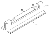
次に、下記特許文献2に開示されている電極の未塗布部側の芯体の端縁と集電体との接合形態を図9〜図12を用いて説明する。なお、図9は下記特許文献2に開示されている電池の巻回電極体に集電体を取り付けた状態を示す斜視図であり、図10は図9の集電体部の部分拡大斜視図であり、図11は図9の集電体のスリットに挿入された電極の未塗布部側の芯体の端縁を屈曲する前の拡大断面図であり、図12は図9の集電体のスリットに挿入された電極の未塗布部側の芯体の端縁を屈曲した後の拡大断面図である。 Next, the joining form between the edge of the core on the uncoated portion side of the electrode and the current collector disclosed in Patent Document 2 will be described with reference to FIGS. 9 is a perspective view showing a state where the current collector is attached to the wound electrode body of the battery disclosed in Patent Document 2 below, and FIG. 10 is a partially enlarged perspective view of the current collector portion of FIG. 11 is an enlarged cross-sectional view of the electrode inserted in the slit of the current collector of FIG. 9 before bending the edge of the uncoated portion of the core, and FIG. 12 is the current collector of FIG. It is an expanded sectional view after bending the edge of the core body by the side of the non-application part of the electrode inserted in this slit.
下記特許文献2に開示されている電池の巻回電極体50には、負極51の集電体52と正極53の集電体(図示せず)が接続固定されるが、負極51の集電体52は、電極巻回体50の長円筒形における中央の直線部と一方の湾曲部の上方を覆う銅合金板であり、この直線部の片側の上方に配置される部分には銅合金板を上方で折り返して下方に向けて開口する間隙を開けて向かい合わせにした挟持部54を設けている。各挟持部54には、折り返しの上端頂部における両端部を除いた部分の銅合金板を削り取ることにより間隙を露出させた窓部55が形成されている。また、電極巻回体50の長円筒形における湾曲部の上方を覆う部分には、銅合金製の負極端子56の下端部が接続固定されている。正極53の集電体は電極巻回体50の長円筒形における中央の直線部の上方と側方と下方及び他方の湾曲部の上方を覆うアルミニウム合金板(図示せず)であり、この直線部の下方の先端側に配置される部分に、アルミニウム合金板を下方で折り返して上方に向けて開口する間隙を開けて向かい合わせにした負極51の集電体52の挟持部54と同様の構成の挟持部を備えている。
A
この上記特許文献2に開示されている電池の挟持部54の窓部55は従来よりも深く、しかも、挟持部54で向かい合う銅合金板の一方から上方に突出する押板片58を残して削り取られる。なお、図12に示す押板片58は、後の工程で押し潰された状態を示す。この押板片58は、挟持部54で向かい合う銅合金板の一方よりも薄い板厚で、窓部55の両端部に隙間を開けた幅の板状として削り出される。そして、上記負極集電体52の挟持部54の間隙には、図11に示すように、電極巻回体50の負極51の上端部の芯体が複数枚ずつ、深く削り取られた窓部55に先端部が十分に突出するように挟み込まれる。このようにして窓部55に突出した負極51の銅箔の先端部は、図12に示すように、押板片58を斜め上方から押し潰すことにより押板片58が突出する側とは反対の方向に屈曲され、この押板片58の先端で屈曲された負極51の芯体を上から押え込むようにして固定される。そして、この押板片58の先端で押え込まれた負極51の芯体の先端をレーザ溶接により周囲の銅合金板に溶接させて接続固定する。この下記特許文献2に開示されている電池の正極集電体の挟持部も負極の集電体の場合と同様の構成を備えている。
The
上記特許文献2に開示されている構成によれば、例えば、負極集電体52の挟持部54の窓部55から突出する負極51の上端部の芯体は先端部が屈曲され固定されるので、これら芯体の先端の溶接が不十分であったり外れたとしても、挟持部54から容易には抜け落ちるようなことがなくなり、また、負極51の上端部の芯体がこのように確実に挟持部54に挟持されるのでこれら芯体の先端の溶接部に無理な力が加わるようなこともなくなり、溶接も外れ難くなる。従って、電池が電気自動車等に搭載されて繰り返し振動や衝撃を受けても、電極巻回体50の負極51や正極53と負極集電体52や正極集電体の接続が外れ易くなるというおそれがなくなり、電池性能の低下を防止することができるようになるというものである。
According to the configuration disclosed in Patent Document 2, for example, the core of the upper end portion of the
上述のような従来例によれば、負極及び正極それぞれの芯体と集電体とをレーザ溶接により接続固定したので、一応電池の内部抵抗が低減し、かつ抵抗のばらつきが少ない電池を得ることができる。しかしながら、上記特許文献1の図7及び図8に示した集電体40のスリット41の構成では、例えば負極43の上端部の多数枚の銅箔からなる芯体44は、束ねられて負極集電体40のスリット41に挟持された状態で上端がレーザ溶接されるだけなので、このレーザ溶接による溶接が不完全になったり、簡単に外れ易くなること、このレーザ溶接部分が外れると負極43は薄い芯体44が他の多数の負極43の芯体44と重なってスリット41に挟まれただけの状態となるので、振動や衝撃を受けた場合に抜け落ちるおそれがあること、及び、一旦負極43の芯体44が1枚でもスリット41から抜け落ちると残りの負極43の芯体44に対する挟持力が弱くなるので、これらの芯体44も抜け落ち易くなるという問題点が存在する。
According to the conventional example as described above, since the core and the current collector of each of the negative electrode and the positive electrode are connected and fixed by laser welding, the internal resistance of the battery is reduced, and a battery with less variation in resistance is obtained. Can do. However, in the configuration of the
加えて、上記特許文献1に開示された接合形態では、束ねられた芯体44の上方からレーザ光が照射されているため、レーザ光の照射時にスパッタリングされた微細な粒子が電極巻回体内部に浸入するため、内部短絡の危険性がある。
In addition, in the joining form disclosed in Patent Document 1, since the laser light is irradiated from above the bundled
また、上記特許文献2に開示されている電池の挟持部54は、従来よりも深く、しかも、挟持部54で向かい合う銅合金板の一方から上方に突出する押板片58を残して削り取られており、電極巻回体50の負極51の上端部の芯体が複数枚ずつ集合されて挟持部54内の深く削り取られた窓部55に先端部が十分に突出するように挟み込まれている。しかしながら、負極51の上端部の芯体の長さは通常一定長とされるから、挟持部54内に挟み込まれた負極51の芯体の先端部は電極巻回体50の厚さに対応する距離差が生じるため、図11に示したような一定の高さに揃うことはなく、図13Aに示したように、挟持部54内の中央部が最も高く、両端部に行くに従って高さが低くなることは明らかである。
In addition, the
したがって、挟持部54の高さL1が低いと、図13Aに示したように、負極51の上端部の芯体が窓部55にまで達しないものが生じる虞が生じる。これを解決するためには、図13Bに示したように、挟持部54の高さL2を大きくするとともに切り欠かれた窓部55を大きくし、露出される負極51の芯体代を増加させることにより解決し得るが、このような構成を採用すると電池缶内の巻回電極体が占めるスペースが減少するため、電池容量が低下するという問題点が存在する。
Therefore, when the height L1 of the
加えて、上記特許文献2に開示されている電極の挟持部54は、少なくとも押板片58の両端側では、集合された負極51の上端部の芯体は、上記特許文献1に開示されているものと同様に、上方に向かって窓部55から露出した状態となる。従って、挟持部54の押板片58が存在していない部分において負極51の上端部の芯体と挟持部54とをレーザ溶接すると、上記特許文献1に開示されているものと同様に、スパッタリングされた微細な粒子によって内部短絡の危険性を生じる。
In addition, the
本発明は、上記のような従来技術の問題点に対処するためになされたものであり、その目的は、レーザ光等の高エネルギー線を用いて電極の露出した芯体と押え板ないし集電体とを溶接する際に、スパッタリングされた微細な粒子が電極体内部に入って内部短絡が生じる虞を減少するとともに、電極の露出した芯体部分の長さが短くても露出した芯体と押え板ないし集電体とを強固に溶接することができる構成の角形電池を提供することにある。 The present invention has been made to address the above-described problems of the prior art, and its purpose is to provide a core body with an electrode exposed using a high energy beam such as a laser beam and a press plate or current collector. When welding the body, it is possible to reduce the possibility that the sputtered fine particles enter the electrode body and cause an internal short circuit, and the exposed core body even if the length of the exposed core part of the electrode is short An object of the present invention is to provide a prismatic battery having a structure capable of firmly welding a pressing plate or a current collector.
上記目的を達成するため、請求項1に係る角形電池の発明は、
正極芯体に正極合剤が塗布された正極と、負極芯体に負極合剤が塗布された負極とがセパレータを介して幅方向に互いにずらして積層或いは巻回された偏平状の電極群と、押え板と、前記押え板に電気的に接続された集電体とを備え、前記正極芯体及び負極芯体の少なくとも一方の幅方向の端部は前記正極合剤又は負極合剤が塗布されていない複数の露出部を有し、前記複数の露出部に押え板が溶接された角形電池において、
前記押え板は、金属板が折り返されて隙間を空けて互いに対向する面が形成されて前記対向する面の少なくとも一方側に折り返し部に沿ったスリットが設けられ、
前記複数の露出部が前記押え板の隙間に挿入されて、前記複数の露出部と前記押え板とが前記スリットを介して実質的に横方向から高エネルギー線により溶接されていることを特徴とする。
In order to achieve the above object, the invention of the prismatic battery according to claim 1 comprises:
A flat electrode group in which a positive electrode in which a positive electrode mixture is applied to a positive electrode core and a negative electrode in which a negative electrode mixture is applied to a negative electrode core are stacked or wound in a widthwise direction with a separator interposed therebetween. A positive plate and a negative electrode mixture are applied to at least one widthwise end of the positive electrode core and the negative electrode core. In a square battery having a plurality of exposed portions that are not, and having a presser plate welded to the plurality of exposed portions,
The presser plate is formed with a metal plate folded back to form a surface facing each other with a gap between them, and provided with a slit along the folded portion on at least one side of the facing surface,
The plurality of exposed portions are inserted into gaps between the presser plates, and the plurality of exposed portions and the presser plates are welded by high energy rays from substantially the lateral direction through the slits. To do.
また、請求項2に係る発明は、請求項1に記載の角形電池において、前記集電体は、実質的に横断面が逆L字型の金具と前記金具から直接帯状に延びている接続部とからなり、前記集電体の逆L字型の金具の内側面が前記押え板の対向する面の一方及び前記折り返し部に当接するように載置されているとともに、前記集電体の逆L字型の金具の前記押え板の対向する面の一方と当接している部分が実質的に横方向から高エネルギー線により溶接されていることを特徴とする。 According to a second aspect of the present invention, in the prismatic battery according to the first aspect, the current collector has a substantially L-shaped bracket having a transverse cross section and a connection portion extending directly from the bracket in a strip shape. The inner surface of the inverted L-shaped metal fitting of the current collector is placed in contact with one of the opposed surfaces of the presser plate and the folded portion, and the reverse of the current collector A portion of the L-shaped metal fitting that is in contact with one of the opposing surfaces of the presser plate is welded by a high energy beam substantially from the lateral direction.
また、請求項3に係る発明は、請求項2に記載の角形電池において、前記集電体の逆L字型の金具の前記押え板の対向する面の一方と当接している部分には前記押え板に設けられたスリットと重複する位置にスリットが設けられ、前記複数の露出部と、前記押え板と、前記集電体の逆L字型の金具とが、前記押え板及び集電体の逆L字型の金具に設けられたそれぞれのスリットを介して実質的に横方向から高エネルギー線により溶接されていることを特徴とする。 According to a third aspect of the present invention, in the prismatic battery according to the second aspect, the portion of the current collector that is in contact with one of the opposing surfaces of the presser plate of the inverted L-shaped metal fitting is the A slit is provided at a position overlapping with the slit provided in the presser plate, and the plurality of exposed portions, the presser plate, and the inverted L-shaped metal fitting of the current collector include the presser plate and the current collector. It is characterized by being welded by a high energy ray substantially from the lateral direction through respective slits provided in the inverted L-shaped metal fitting.
また、請求項4に係る発明は、請求項1〜3のいずれかに記載の角形電池において、前記高エネルギー線はレーザ光又は電子ビームからなることを特徴とする。 According to a fourth aspect of the present invention, in the prismatic battery according to any one of the first to third aspects, the high energy beam is formed of a laser beam or an electron beam.
更に、上記目的を解決するため、請求項5に係る角形電池の発明は、
正極芯体に正極合剤が塗布された正極と、負極芯体に負極合剤が塗布された負極とがセパレータを介して幅方向に互いにずらして積層或いは巻回された偏平状の電極群と集電体とを備え、前記正極芯体及び負極芯体の少なくとも一方の幅方向の端部は前記正極合剤又は負極合剤が塗布されていない複数の露出部を有し、前記複数の露出部に押え板が溶接された角形電池において、
前記集電体は、金属板がコ字状に折り返されて隙間を空けて互いに対向する対向面と前記対向面間を接続する面が形成され、前記対向面のそれぞれに前記折り返し部に沿ったスリットが設けられているとともに、前記対向面間を接続する面から直接帯状に延びている接続部が形成されており、
前記複数の露出部は2組に分けられてこれらの2組の露出部間に配置された押え板とともに前記集電体の対向面間の隙間に挿入され、
前記2組の露出部と、前記押え板と、前記集電体のそれぞれの対向面とが前記集電体の対向面のそれぞれに設けられたスリットを介して実質的に横方向から高エネルギー線により溶接されていることを特徴とする。
Furthermore, in order to solve the above object, the invention of the prismatic battery according to claim 5 is:
A flat electrode group in which a positive electrode in which a positive electrode mixture is applied to a positive electrode core and a negative electrode in which a negative electrode mixture is applied to a negative electrode core are stacked or wound in a widthwise direction with a separator interposed therebetween. And at least one end in the width direction of the positive electrode core and the negative electrode core has a plurality of exposed portions to which the positive electrode mixture or the negative electrode mixture is not applied, and the plurality of exposures In a square battery with a presser plate welded to the part,
In the current collector, a metal plate is folded in a U-shape to form a facing surface that faces each other with a gap therebetween and a surface that connects the facing surfaces, and each of the facing surfaces extends along the folded portion. A slit is provided, and a connecting portion is formed extending directly from the surface connecting the opposing surfaces in a band shape,
The plurality of exposed portions are divided into two sets and inserted into a gap between the opposing surfaces of the current collector together with a holding plate disposed between the two sets of exposed portions,
The two sets of exposed portions, the presser plate, and the opposing surfaces of the current collector are high energy rays from substantially the lateral direction through slits provided on the opposing surfaces of the current collector. It is welded by.
また、請求項6に係る発明は、請求項5に記載の角形電池において、前記押え板は金属板がコ字状に折り返されて隙間を空けて互いに対向する対向面が形成されており、前記押え板の対向面の外側がともに前記露出部と接する状態で前記集電体の隙間に挿入されていることを特徴とする。 Further, the invention according to claim 6 is the prismatic battery according to claim 5, wherein the presser plate has a metal plate folded back in a U-shape to form a facing surface facing each other with a gap therebetween, It is characterized by being inserted in the gap of the current collector in a state where both outer sides of the opposing surface of the presser plate are in contact with the exposed portion.
また、請求項7に係る発明は、請求項5又は6に記載の角形電池において、前記高エネルギー線はレーザ光又は電子ビームからなることを特徴とする。 The invention according to claim 7 is the prismatic battery according to claim 5 or 6, characterized in that the high energy beam is composed of a laser beam or an electron beam.
更に、上記目的を解決するため、請求項8に係る角形電池の発明は、
正極芯体に正極合剤が塗布された正極と、負極芯体に負極合剤が塗布された負極とがセパレータを介して幅方向に互いにずらして積層或いは巻回された偏平状の電極群と集電体とを備え、前記正極芯体及び負極芯体の少なくとも一方の幅方向の端部は前記正極合剤又は負極合剤が塗布されていない複数の露出部を有し、前記複数の露出部に押え板が溶接された角形電池において、
前記集電体は、金属板がコ字状に折り返されて隙間を空けて互いに対向する対向面と前記対向面間を接続する面が形成され、前記対向面のそれぞれに前記折り返し部に沿ったスリットが設けられているとともに、前記対向面間を接続する面から直接帯状に延びている接続部が形成されており、
前記押え板は、金属板が折り返されて隙間を空けて互いに対向する面が形成された押え部が2個、それぞれ互いに平行にかつ互いに所定間隔を空けて一体に形成されているとともに、前記2つの押え部の互いに外側に位置する面にそれぞれ前記折り返し部に沿ったスリットが設けられており、
前記複数の露出部は2組に分けられてこれらの2組の露出部のそれぞれが前記2つの押え部の隙間に挿入された状態で前記集電体の対向面間の隙間に挿入され、
前記2組の複数の露出部と、前記押え板と、前記集電体のそれぞれの対向面とが、前記集電体の対向面にそれぞれ設けられたスリット及び前記押え板の外側に位置する面にそれぞれ設けられたスリットを介して実質的に横方向から高エネルギー線により溶接されていることを特徴とする。
また、請求項9に係る発明は、請求項8に記載の角形電池において、前記高エネルギー線はレーザ光又は電子ビームからなることを特徴とする。
Furthermore, in order to solve the above-mentioned object, the invention of the prismatic battery according to claim 8
A flat electrode group in which a positive electrode in which a positive electrode mixture is applied to a positive electrode core and a negative electrode in which a negative electrode mixture is applied to a negative electrode core are stacked or wound in a widthwise direction with a separator interposed therebetween. And at least one end in the width direction of the positive electrode core and the negative electrode core has a plurality of exposed portions to which the positive electrode mixture or the negative electrode mixture is not applied, and the plurality of exposures In a square battery with a presser plate welded to the part,
In the current collector, a metal plate is folded in a U-shape to form a facing surface that faces each other with a gap therebetween and a surface that connects the facing surfaces, and each of the facing surfaces extends along the folded portion. A slit is provided, and a connecting portion is formed extending directly from the surface connecting the opposing surfaces in a band shape,
The presser plate is formed integrally with two presser portions, each of which has a metal plate folded back to form a surface facing each other with a gap therebetween, in parallel with each other at a predetermined interval. Slits are provided along the folded portions on the surfaces of the two presser portions located on the outer sides,
The plurality of exposed portions are divided into two sets, and each of these two sets of exposed portions is inserted into the gap between the opposing surfaces of the current collector in a state where the two exposed portions are inserted into the gap between the two pressing portions,
The two sets of the plurality of exposed portions, the pressing plate, and the respective facing surfaces of the current collector are respectively provided with slits provided on the facing surface of the current collector and a surface located outside the pressing plate. It welds with the high energy ray from the horizontal direction substantially through the slit provided in each.
According to a ninth aspect of the present invention, in the prismatic battery according to the eighth aspect, the high energy beam is composed of a laser beam or an electron beam.
本発明は上記の構成を備えることにより以下に述べるような優れた効果を奏する。すなわち、請求項1に係る発明によれば、押え板は金属板が折り返されて隙間を空けて互いに対向する面が形成されているとともに前記対向する面の少なくとも一方側に折り返し部に沿ったスリットが設けられているから、この押え板の隙間に挿入された正極芯体ないし負極芯体の露出部は横方向からの高エネルギー線により溶接されている。したがって、スパッタリングされた微粒子は高エネルギー線の進行方向、即ち実質的に水平方向に飛散するため、電極群の内部にまで浸入することがなくなるので、内部短絡の可能性が少ない角形電池が得られる。加えて、高エネルギー線の溶接エネルギーが大きすぎた場合でも角形電池の電極群にダメージを与えることはほとんどなくなる。 By providing the above configuration, the present invention has the following excellent effects. That is, according to the first aspect of the present invention, the presser plate has a metal plate folded back to form a surface facing each other with a gap therebetween, and a slit along the folded portion on at least one side of the facing surface. Therefore, the exposed portion of the positive electrode core body or the negative electrode core body inserted into the gap of the presser plate is welded by high energy rays from the lateral direction. Therefore, since the sputtered fine particles are scattered in the traveling direction of the high-energy rays, that is, substantially in the horizontal direction, the sputtered fine particles do not penetrate into the electrode group, so that a rectangular battery with less possibility of internal short-circuit can be obtained. . In addition, even if the welding energy of the high energy beam is too large, the electrode group of the prismatic battery is hardly damaged.
また、押え板の隙間に挿入された複数の正極芯体ないし負極芯体の露出部は、これらの芯体の露出部代は一定であるため、これらの芯体の先端部は偏平状の電極群の厚さに対応する距離差が生じるので、押え板の中央部が最も高い位置まで延び、両端部に行くに従って高さが低くなる。しかしながら、請求項1に係る発明によれば、押え板として金属板が折り返されて隙間を空けて互いに対向する面が形成されているとともに前記対向する面の少なくとも一方側に折り返し部に沿ったスリットが設けられているものを使用したから、押え板のスリットが設けられている位置、即ち溶接箇所は従来例のものに比すると露出部の根本に近くなるので、芯体の露出代を大きくしなくても全ての芯体の露出部と押え板とを確実に溶接した角形電池が得られる。 Further, the exposed portions of the plurality of positive electrode cores or negative electrode cores inserted into the gaps of the holding plate have a constant exposed portion cost, so that the tips of these cores are flat electrodes. Since a distance difference corresponding to the thickness of the group is generated, the center portion of the press plate extends to the highest position, and the height decreases as it goes to both end portions. However, according to the first aspect of the present invention, the metal plate is folded back as the presser plate to form a surface facing each other with a gap therebetween, and the slit along the folded portion on at least one side of the facing surface Therefore, the position where the slit of the presser plate is provided, that is, the welded part is closer to the root of the exposed part than the conventional example, so the exposure of the core is increased. Even if it does not exist, the square battery which welded the exposed part and presser plate of all the core bodies reliably can be obtained.
また、請求項2に係る発明によれば、集電体の実質的に断面が逆L字型の金具の内側面が押え板の対向する面の一方及び折り返し部に当接するように載置されているとともに、逆L字型の金具の押え板の対向する面の一方と当接している部分を実質的に横方向から高エネルギー線により溶接したから、逆L字状の金具の取付強度が大きくなるとともに、逆L字状の金具から直接帯状に延びている接続部として押え板の折り返し部よりも幅が太いものを使用し得るため、大電流を取り出すことができる角形電池が得られる。 According to the second aspect of the present invention, the current collector is mounted so that the inner surface of the inverted L-shaped metal fitting is in contact with one of the opposing surfaces of the holding plate and the folded portion. At the same time, the portion of the reverse L-shaped metal fitting that is in contact with one of the opposing surfaces of the presser plate is welded substantially from the lateral direction with a high energy ray, so that the mounting strength of the reverse L-shaped metal fitting is high. Since the connection portion that is larger and wider than the folded portion of the presser plate can be used as the connection portion that directly extends from the inverted L-shaped metal fitting in a band shape, a rectangular battery that can take out a large current can be obtained.
また、請求項3に係る発明によれば、実質的に断面が逆L字型の金具の押え板の対向する面の一方と当接している部分には押え板に設けられたスリットと重複する位置にスリットを設けたから、前記正極芯体及び負極芯体の少なくとも一方の複数の露出部と、前記押え板と、前記、逆L字型の金具の押え板とをそれぞれのスリットを介して同時に溶接できるようになるため、製造工数を増やすことなく金属製端子を押え板に取り付けることができるようになる。 According to the invention of claim 3, the portion that is substantially in contact with one of the opposing surfaces of the presser plate of the inverted L-shaped fitting overlaps with the slit provided in the presser plate. Since the slit is provided at the position, the plurality of exposed portions of at least one of the positive electrode core body and the negative electrode core body, the presser plate, and the presser plate of the inverted L-shaped metal fitting are simultaneously passed through the respective slits. Since welding can be performed, the metal terminal can be attached to the holding plate without increasing the number of manufacturing steps.
また、請求項4に係る発明によれば、レーザ光及び電子ビームともに溶接用高エネルギー線として慣用的に用いられており、溶接部の信頼性及び品質が良好な角形電池が得られる。 According to the invention of claim 4, both the laser beam and the electron beam are conventionally used as high energy beams for welding, and a prismatic battery with good welded portion reliability and quality can be obtained.
更に、請求項5に係る発明によれば、電極群の厚さが厚く、集電体の対向面間の隙間に挿入される正極芯体ないし負極芯体の露出部の数が多くなっても、これらの芯体の複数の露出部を2組に分けるとそれぞれの組の露出部から見れば電極群の厚さを薄くした場合と等価になるため、これらの芯体の露出部代を特に大きくしなくても、2組の複数の露出部と、押え板と、集電体とを、これら集電体の対向面の両方に設けられたスリットを介して両側から実質的に横方向の高エネルギー線によって一体に溶接することができるようになり、実質的に請求項1に係る発明と同様の効果が得られる外、より大電流を取り出すことができる角形電池が得られる。 Further, according to the invention according to claim 5, even if the thickness of the electrode group is large and the number of exposed portions of the positive electrode core or the negative electrode core inserted into the gap between the opposing surfaces of the current collector increases. If the exposed portions of these cores are divided into two sets, it is equivalent to the case where the thickness of the electrode group is reduced when viewed from the exposed portions of each set. Even if it is not enlarged, two sets of the plurality of exposed portions, the holding plate, and the current collector are substantially laterally extended from both sides through slits provided on both opposing surfaces of these current collectors. A high-energy beam can be integrally welded, so that substantially the same effect as that of the invention according to claim 1 can be obtained, and a rectangular battery capable of taking out a larger current can be obtained.
また、請求項6に係る発明によれば、押え板の対向面同士の弾性力によって、2組の複数の露出部と押え板とを集電体の対向面間の隙間に挿入した際、押え板の対向面により2組の複数の露出部のそれぞれに対して集電体の対応面に向かう押圧力を与えることができるため、溶接する前に2組の複数の露出部と押え板と集電体とを一体的に固定でき、高エネルギー線による溶接を安定して行うことができるようになる。 According to the invention of claim 6, when the two sets of the plurality of exposed portions and the presser plate are inserted into the gap between the opposing surfaces of the current collector by the elastic force between the opposing surfaces of the presser plate, the presser Since the opposing surface of the plate can apply a pressing force toward the corresponding surface of the current collector to each of the two sets of the plurality of exposed portions, the two sets of the plurality of exposed portions, the presser plate, and the collector are collected before welding. The electric body can be fixed integrally, and welding with high energy rays can be performed stably.
また、請求項7に係る発明によれば、請求項6に係る発明の効果に加えて、更に請求項4に係る発明と同様の効果を奏することができる角形電池が得られる。 According to the invention of claim 7, in addition to the effect of the invention of claim 6, a prismatic battery that can exhibit the same effect as the invention of claim 4 can be obtained.
また、請求項8に係る発明によれば、電極群の厚さが厚く、押え板の隙間に挿入される正極芯体ないし負極芯体の露出部の数が多くなっても、これらの芯体の複数の露出部を2組に分けるとそれぞれの組の露出部から見れば電極群の厚さを薄くした場合と等価になるため、これらの芯体の露出部代を特に大きくしなくても、2組の複数の露出部のそれぞれを押え板の2つの押え部の隙間に挿入した状態で、2組の複数の露出部と、押え板と、集電体のそれぞれの対向面とを、集電体の対向面にそれぞれ設けられたスリット及び押え板の外側に位置する面にそれぞれ設けられたスリットを介して、実質的に横方向から高エネルギー線一体に溶接することができるようになり、実質的に請求項1に係る発明と同様の効果が得られる外、より大電流を取り出すことができる角形電池が得られる。 Further, according to the invention according to claim 8, even if the electrode group is thick and the number of exposed portions of the positive electrode core or the negative electrode core inserted into the gap of the presser plate increases, these cores If the plurality of exposed portions are divided into two sets, it is equivalent to the case where the thickness of the electrode group is reduced when viewed from the exposed portions of each set. Therefore, even if the exposed portion cost of these cores is not particularly large With each of the two sets of the plurality of exposed portions inserted into the gap between the two presser portions of the presser plate, the two sets of the plurality of exposed portions, the presser plate, and the respective opposing surfaces of the current collector, High energy lines can be welded substantially from the lateral direction through the slits provided on the opposing surfaces of the current collector and the slits provided on the outer surface of the holding plate. In addition to substantially the same effect as that of the invention according to claim 1, a larger current is obtained. Prismatic battery can be taken out can be obtained.
また、請求項9に係る発明によれば、請求項8に係る発明の効果に加えて、更に請求項4に係る発明と同様の効果を奏することができる角形電池が得られる。 According to the invention of claim 9, in addition to the effect of the invention of claim 8, a prismatic battery that can exhibit the same effect as the invention of claim 4 can be obtained.
以下、本願発明を実施するための最良の形態を巻回された偏平状の電極群を用いた角形電池の場合を例にとり、実施例及び比較例を用いて図面を参照しながら詳細に説明する。ただし、以下に示す実施例は、本発明の技術思想を具体化するための巻回された偏平状の電極群を用いた角形電池の一例を例示するものであって、本発明をこの実施例に特定することを意図するものではなく、本発明は例えば正極板及び負極板をそれぞれセパレータを介して複数枚積層した積層型の電極群の場合等、特許請求の範囲に示した技術思想を逸脱することなく種々の変更を行ったものにも均しく適用し得るものである。なお、この発明における高エネルギー線の照射方向を示す「実質的に横方向」とは、完全に水平な方向だけでなく、水平方向からある程度傾いていても実質的に横方向と見なされる範囲を含むものである。この傾きは何ら臨界的なものではなく、具体的には完全に水平な方向を基準として約±30°程度の範囲にあればよい。 Hereinafter, the best mode for carrying out the present invention will be described in detail with reference to the drawings using examples and comparative examples, taking as an example the case of a rectangular battery using a flat electrode group wound with a coil. . However, the embodiment shown below exemplifies an example of a square battery using a wound flat electrode group for embodying the technical idea of the present invention. The present invention deviates from the technical idea shown in the claims, for example, in the case of a laminated electrode group in which a plurality of positive and negative electrode plates are laminated via separators, respectively. The present invention can be applied evenly to various changes made without doing so. The “substantially lateral direction” indicating the irradiation direction of the high energy ray in the present invention is not only a completely horizontal direction but also a range that is substantially regarded as a lateral direction even if it is inclined to some extent from the horizontal direction. Is included. This inclination is not critical at all, and specifically, it may be in a range of about ± 30 ° with respect to a completely horizontal direction.
まず、実施例及び比較例で使用する巻回された偏平状の電極群の作製方法について説明する。 First, a method for producing a wound flat electrode group used in Examples and Comparative Examples will be described.
〔正極の作製〕
正極は次のようにして作製した。まず、コバルト酸リチウムからなる正極活物質94質量%をアセチレンブラック、グラファイト等の炭素粉末3質量%と、ポリビニリデンフルオライド(PVdF)よりなる結着剤3質量%とを混合し、得られた混合物にN−メチルピロリドンを加えて混練して活物質合剤スラリーを作製した。これらの活物質合剤スラリーを厚さが20μmのアルミニウム箔からなる正極芯体の片面に、電極の端部にはアルミニウム箔の露出部ができるようにして、均一に塗付して活物質層を塗布した正極板を形成した。この後、活物質層を塗布した正極板を乾燥機中に通過させて、スラリー作製時に必要であった有機溶剤を除去して乾燥させた。乾燥後、この乾燥正極板をロールプレス機により圧延して、厚みが0.06mmの正極板とした。このようにして作製された電極を幅96mmの短冊状に切り出し、幅10mmの帯状のアルミニウム箔露出部を設けた正極を得た。
[Production of positive electrode]
The positive electrode was produced as follows. First, 94% by mass of a positive electrode active material composed of lithium cobaltate was obtained by mixing 3% by mass of carbon powder such as acetylene black and graphite and 3% by mass of a binder composed of polyvinylidene fluoride (PVdF). N-methylpyrrolidone was added to the mixture and kneaded to prepare an active material mixture slurry. These active material mixture slurries are uniformly applied on one side of a positive electrode core body made of an aluminum foil having a thickness of 20 μm so that an exposed portion of the aluminum foil is formed at the end of the electrode. A positive electrode plate coated with was formed. Thereafter, the positive electrode plate coated with the active material layer was passed through a drier to remove the organic solvent necessary for the slurry preparation and dry the slurry. After drying, this dried positive electrode plate was rolled by a roll press to obtain a positive electrode plate having a thickness of 0.06 mm. The electrode thus produced was cut into a strip having a width of 96 mm to obtain a positive electrode provided with a strip-shaped aluminum foil exposed portion having a width of 10 mm.
〔負極の作製〕
負極は次のようにして作製した。まず、黒鉛粉末98質量%、カルボキシメチルセルロース、スチレンブタジエンゴムをそれぞれ1質量%混合し、水を加えて混練してスラリーを作製した。このスラリーを厚さ12μmの銅箔からなる負極芯体の片面に、電極の端部には銅箔の露出部ができるように均一に塗布して負極活物質層を塗布した負極板を得た。この後、活物質層を塗布した負極板を乾燥機中に通過させて、スラリー作製時に必要であった水を除去して乾燥させた。乾燥後、この乾燥負極板をロールプレス機により圧延して、厚みが0.05mmの負極板とした。次いで、得られた電極を幅98mmの短冊状に切り出し、幅8mmの帯状の銅箔露出部を設けた負極を得た。
(Production of negative electrode)
The negative electrode was produced as follows. First, 98% by mass of graphite powder, 1% by mass of carboxymethyl cellulose and styrene butadiene rubber were mixed, and water was added to knead to prepare a slurry. The slurry was uniformly applied on one side of a negative electrode core made of a copper foil having a thickness of 12 μm so that an exposed portion of the copper foil was formed at the end of the electrode, and a negative electrode plate coated with a negative electrode active material layer was obtained. . Thereafter, the negative electrode plate coated with the active material layer was passed through a dryer to remove water necessary for slurry preparation and dried. After drying, the dried negative electrode plate was rolled by a roll press to obtain a negative electrode plate having a thickness of 0.05 mm. Next, the obtained electrode was cut into a strip shape having a width of 98 mm to obtain a negative electrode provided with a strip-shaped copper foil exposed portion having a width of 8 mm.
〔巻回された偏平状の電極群の作製〕
上述のようにして得られた正極板のアルミニウム箔露出部と負極板の銅箔露出部とがそれぞれ対向する電極の活物質層と重ならないようにずらして、厚さ0.022mmのポリエチレン製多孔質セパレータを介して巻回し、両側端にそれぞれ複数のアルミニウム箔露出部と複数の銅箔露出部が形成された実施例及び比較例で使用する巻回された偏平状の電極群10を作製した。
[Preparation of wound flat electrode group]
The polyethylene foil having a thickness of 0.022 mm is shifted so that the aluminum foil exposed portion of the positive electrode plate and the copper foil exposed portion of the negative electrode plate obtained as described above do not overlap with the active material layers of the electrodes facing each other. Wound through a quality separator, a wound
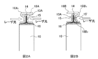
実施例1の角形電池を図1〜図3を用いて説明する。なお、図1Aは巻回された偏平状の電極群に押え板を取り付けた状態の斜視図であり、図1Bは図1AのIB−IB断面図である。図2Aは図1の偏平状の電極群に取り付けられた押え板上に更にスリットを有しない集電体を取り付けた状態の、図2Bは同じくスリットを有する集電体を取り付けた状態の、それぞれ図1のIB−IB断面図に対応する断面図である。また、図3は図2Bに示したスリットを有する集電体を取り付けた偏平状の電極群を電池外装缶内に組み込んだ実施例1の角形電池の部分断面図である。 The prismatic battery of Example 1 will be described with reference to FIGS. 1A is a perspective view of a state where a presser plate is attached to a wound flat electrode group, and FIG. 1B is a cross-sectional view taken along the line IB-IB in FIG. 1A. FIG. 2A shows a state in which a current collector not having a slit is further attached on the presser plate attached to the flat electrode group in FIG. 1, and FIG. 2B shows a state in which a current collector having a slit is also attached. It is sectional drawing corresponding to IB-IB sectional drawing of FIG. FIG. 3 is a partial cross-sectional view of the prismatic battery of Example 1 in which a flat electrode group to which a current collector having a slit shown in FIG. 2B is attached is incorporated in a battery outer can.
この実施例1の角形電池における偏平状の電極群10には、金属板を折り返し部14で折り返すことにより隙間を空けて互いに対向する面11A、12Aが形成された押え板13Aが取り付けられている。この押え板13Aの互いに対向する面11A及び12Aの少なくとも一方側には折り返し部14に沿って実質的に平行にスリット15が設けられている。そして、巻回された偏平状の電極群10から延びる正極芯体ないしは負極芯体の複数の露出部16が押え板13Aの隙間に挿入され、正極芯体ないしは負極芯体の複数の露出部16と押え板13Aとをスリット15を介してレーザ光を実質的に横方向から照射することにより一体に溶接されている。
The
このような構成によれば、レーザ光を照射して溶接した際にスパッタリングされた微粒子は、レーザ光の進行方向、即ち実質的に水平方向に飛散するため、巻回された偏平状の電極群10の内部にまで浸入することがなくなるので、内部短絡の可能性が少なくなる。更に、レーザ光の溶接エネルギーが大きすぎた場合、スリットが設けられた面12Aに対向する面11Aをレーザ光が貫通してしまうこととなるが、このような状態となっても巻回された偏平状の電極群10にダメージを与えることはほとんどなくなる。
According to such a configuration, the fine particles sputtered when the laser beam is irradiated and welded are scattered in the traveling direction of the laser beam, that is, substantially in the horizontal direction. Since it does not penetrate into the inside of 10, the possibility of an internal short circuit is reduced. Furthermore, when the welding energy of the laser beam is too large, the laser beam will penetrate the
また、押え板13Aの隙間に挿入された複数の正極芯体ないし負極芯体の露出部16は、図1Bに示したように、これらの芯体の露出部代は一定であるため、これらの芯体の先端部は巻回された偏平状の電極群10の厚さに対応する距離差が生じるので、押え板の中央部が最も高い位置まで延び、両端部に行くに従って高さが低くなる。しかしながら、実施例1で採用された押え板13Aによれば、押え板13Aのスリット15が設けられている位置が従来例のものに比すると芯体の露出部16の根本に近くなるので、芯体の露出代を大きくしなくても全ての芯体の露出部16と押え板13Aとを溶接することができるようになる。
In addition, as shown in FIG. 1B, the exposed
なお、押え板13Aは、図示しない電池外装缶に設けられた外部出力端子と集電体によって接続する必要がある。そこで、実施例1の角形電池の集電体18Aとしては、図2Aに示すように、実質的に横断面が逆L字型の金具とこの金具から直接帯状に延びている接続部(図示せず)とを有するものを使用した。そして、この集電体18Aの内側面が押え板13Aの対向する面の一方及び前記折り返し部14に当接するように載置し、この逆L字型の金具のうち前記押え板13Aの対向する面の一方と当接している部分を、別途押え板13Aのスリット15が設けられている方向とは逆の方向から、かつ実質的に横方向からレーザ光により溶接した。
The
このような実施例1の角形電池の集電体18Aでは、集電体18Aを押え板13Aに溶接する必要があるため、レーザ溶接工程が1回増えるが、逆L字型の金具から直接帯状に延びている接続部の幅を押え板13Aの折り返し部14の幅よりも十分に広くすることができるため、大電流を取り出すことができる角形電池が得られる。
In such a prismatic battery
なお、この集電体18Aの逆L字型の金具の折り曲げ部分は、必ずしも直角に曲がっている必要はなく、符号18A1で示した折り曲げ部分のように曲線状のふくらみを持たせて実質的に逆L字型となるようにしてもよい。このような構成とすることにより、集電体18Aや押え板13Aの形状に誤差があっても、集電体18Aの取付・固定が容易となる。更に、押え板13Aの下端側に正極芯体ないしは負極芯体の複数の露出部16の上部に広がるスカート状部分13A1を設けてもよい。このような構成を採用すると、押え板13Aが動き難くなるので、電池に振動等が加わっても押え板13Aと正極芯体ないしは負極芯体の複数の露出部16との間の接触抵抗が大きくなることが少なくなる。
Incidentally, the bent portion of the reversed L-shaped bracket of the
また、実施例1の角形電池の集電体の変形例としては、図2Bに示すように、スリットを有する集電体18Bを採用できる。この図2Bに示した集電体18Bは、実質的に横断面が逆L字型の金具と前記金具から直接帯状に延びている接続部21(図3参照)とを備えているとともに、スリット15'を有している。この変形例の場合、集電体18Bのスリット15'と押え板13Aのスリット15が重なるように配置してレーザ溶接する以外は前記集電体18Aの場合と同様であるが、レーザ溶接工程は一回ですむ。この実施例1の変形例の場合も、集電体18Bの逆L字型の金具の折り曲げ部分は符号18B1で示した折り曲げ部分のように曲線状のふくらみを持たせて実質的に逆L字型となるようにしてもよく、更に、押え板13Aの下端側に正極芯体ないしは負極芯体の複数の露出部16の上部に広がるスカート状部分13A1及び逆L型の金具の下端部にもスカート部分18B2を設けてもよい。
Further, as a modification of the current collector of the prismatic battery of Example 1, a
この図2Bに示した実施例1の変形例の集電体18Bを採用した角形電池20の部分断面図を図3に示す。この角形電池20は、巻回された偏平状の電極群10の正極側には例えば押え板13Aが取り付けられており、この押え板13Aには図2Bに示したような構成の集電体18Bが取り付けられ、この集電体18Bの接続部21は封口板22に絶縁性物質23を介して取り付けられた正極外部端子24に接続されている。同様にして、巻回された偏平状の電極群10の負極側には押え板13A'が取り付けられており、この押え板13A'には集電体18B'が取り付けられ、この集電体18B'の接続部21'は封口板22に絶縁性物質23'を介して取り付けられた負極外部端子24'に接続されている。
FIG. 3 shows a partial cross-sectional view of a
そして、封口板22と一体化された巻回された電極群10を電池外装缶25内に挿入し、封口板22の周囲と電池外装缶25の接合部26をレーザ溶接し、図示しない電解液注入孔から所定量の所定の組成の電解液を注入した後、電解液注入孔を密閉することにより角形電池20が完成される。なお、電解液としては、エチレンカーボネートとジエチルカーボネ一卜を体積比3:7で混合した溶媒に対し、LiPF6を1モル/Lとなるように溶解した非水電解液等を使用することができる。このようにして得られた角形電池20は、正極芯体ないしは負極芯体の複数の露出部16と押え板13A、13A'との間の接触面積が非常に大きく、しかも、押え板13A、13A'と集電体18B、18B'との間、及び集電体18B、18B'と正極外部端子24ないし負極外部端子24'との間の抵抗も低いため、大電流が必要とされるEV、HEV用電池として最適となる。
Then, the
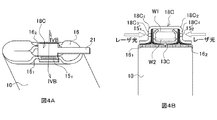
巻回された偏平状の電極群10の厚さが厚くなると、実施例1に示したような押え板13Aの構成では、押え板13Aの隙間に挿入される正極芯体ないし負極芯体の露出部16の数が多くなるので、露出代を大きくしないと全ての露出部16が押え板13Aの隙間内に入らない場合が生じる。そこで、実施例2として厚さが厚い巻回された偏平状の電極群に集電体を取り付けた角形電池の構成を図4を参照して説明する。なお、図4Aは実施例2の角形電池の巻回された偏平状の電極群に集電体を取り付けた状態の斜視図であり、図4Bは図4AのIVB−IVB断面図であり、図4A及び図4Bにおいては実施例1の角形電池の集電構造と同一の構成部分には同一の参照符号を付与して説明する。
When the thickness of the wound
実施例2の角形電池における偏平状の電極群10には、金属板を間隔を開けて2箇所の折り返し部18C1及び18C2で折り返すことにより、実質的にコ字状の、隙間W1を空けて互いに対向する面18C3及び18C4が形成された集電体18Cが取り付けられており、この集電体18Cは互いに対向する面18C3及び18C4の両方側に折り返し部18C1及び18C2に沿って実質的に平行にスリット151'及び152'が設けられている。そして、巻回された偏平状の電極群10から延びる正極芯体ないしは負極芯体の複数の露出部16を偏平部分において2組に分けて束ね、それぞれ第1の露出部161および第2の露出部162とした。そして、第1の露出部161及び第2の露出部162の間に押え板13Cを配置し、図4Bに示したように、この第1の露出部161、第2の露出部162及び押え板13Cを同時に集電体18Cの互いに対向する面18C3及び18C4の間に挿入した。
The flat-shaped
この押え板13Cの横幅W2は、集電体18Cの互いに対向する面18C3及び18C4の隙間W1と少なくとも正極芯体ないしは負極芯体の第1の露出部161の幅と第2の露出部162の幅との和W3との差、すなわちW2=W1−W3の関係を満たしていればよく、その形状は任意である。しかしながら、押え板13Cによって正極芯体ないしは負極芯体の第1の露出部161と第2の露出部162を集電体18Cの互いに対向する面18C3及び18C4側に押圧することができるようにするため、図4Bに示したように、押え板13Cは金属板が折り返されて隙間を空けて互いに対向する面が形成されたものとし、この押え板13Cの互いに対向する面間に隙間を形成することによりこれらの面が変位できるようにして弾性力を発揮できるようにするとよい。
The lateral width W2 of the
このようにして第1の露出部161と押え板13C、及び、押え板13Cと第2の露出部162とを、それぞれ集電体18Cの互いに対向する面18C3及び18C4に設けられた2つのスリット151'及び152'を介して両側からレーザ光を照射することにより、一体に溶接することができる。この実施例2の角形電池によれば、実質的に実施例1の角形電池20の場合と同様の効果が得られる外、より大電流を取り出すことができる大型の角形電池が得られる。
In this way, the first exposed
実施例3の角形電池は、実施例2の場合と同様に、巻回された偏平状の電極群10の厚さが厚い場合に適用したものであるが、押え板として実施例1の角形電池の押え板13Aと同様の構成のものを2個一体に組み合わせたものを使用したものである。この実施例3の角形電池における巻回された偏平状の電極群に集電体を取り付けた構成を図5を用いて説明する。なお、図5は実施例3の角形電池における巻回された偏平状の電極群に集電体を取り付けた状態を示す図4AのIVB−IVB断面図に対応する断面図であり、実施例2の角形電池の集電体18Cと同一の構成部分には同一の参照符号を付与して説明する。
The square battery of Example 3 is applied when the thickness of the wound
この実施例3の角形電池における偏平状の電極群10には、金属板を間隔を開けて2箇所の折り返し部18D1及び18D2で折り返すことにより、実質的にコ字状の、隙間を空けて互いに対向する面18D3及び18D4が形成された集電体18Dが取り付けられており、この集電体18Dは互いに対向する面18D3及び18D4の両方側に折り返し部18D1及び18D2に沿って実質的に平行にスリット151'及び152'が設けられている。そして、巻回された偏平状の電極群10から延びる正極芯体ないしは負極芯体の複数の露出部16を偏平部分において2組に分けて束ね、それぞれ第1の露出部161および第2の露出部162とした。
The flat-shaped
また、押え板13Dとしては、金属板が折り返されて隙間を空けて互いに対向する面が形成された2つの押え部191、192がそれぞれ互いに平行にかつ互いに所定間隔を空けて一体に形成されているとともに、2つの押え部191、192の互いに外側に位置する面にそれぞれ折り返し部に沿ったスリット151、152を設けたものを使用した。そして、第1の露出部161及び第2の露出部162を押え板13Dのそれぞれ2つの押え部191、192の隙間内に配置し、この第1の露出部161、第2の露出部162及び押え板13Dを同時に、図5に示したように、集電体18Dの互いに対向する面18D3及び18D4の間に挿入した。
In addition, as the
このようにして第1の露出部161と押え板13Dの一方の押え部191、及び、押え板13Dの他方の押え部192と第2の露出部162とを、それぞれ集電体18Dの互いに対向する面18D3及び18D4に設けられた2つのスリット151'、152'、及び、2つの押え部191、192の互いに外側に位置する面に設けられた2つのスリット151、152を介して両側からレーザ光を照射することにより、一体に溶接することができる。この実施例3の角形電池によれば、実質的に実施例2の角形電池の場合と同様の効果が得られる。
One of the
[比較例1]
比較例1の角形電池においては、正極芯体ないしは負極芯体の露出部と集電体との間の溶接方法としてレーザ溶接法を採用したが、レーザ光の照射方向を実施例1〜3とは異なり、正極芯体ないしは負極芯体の露出部に対し垂直方向から行った。この比較例1の角形電池の巻回された偏平状の電極群に集電体を取り付けた状態を図6を用いて説明する。なお、図6Aは比較例1の角形電池の巻回された偏平状の電極群に集電体を取り付けた状態の斜視図であり、図6Bは図6AのVIB−VIB断面図である。
[Comparative Example 1]
In the prismatic battery of Comparative Example 1, a laser welding method was employed as a welding method between the exposed portion of the positive electrode core or the negative electrode core and the current collector. Is different from the vertical direction with respect to the exposed portion of the positive electrode core or the negative electrode core. A state in which the current collector is attached to the flat electrode group around which the rectangular battery of Comparative Example 1 is wound will be described with reference to FIG. 6A is a perspective view of a state in which the current collector is attached to the flat electrode group around which the rectangular battery of Comparative Example 1 is wound, and FIG. 6B is a cross-sectional view taken along the line VIB-VIB of FIG. 6A.
この比較例1の角形電池で使用する集電体18Eとしては、金属板がコ字状に折り返されて隙間を空けて互いに対向する面18E3及び18E4と前記互いに対向する面18E3及び18E4の間を接続する面が形成され、前記互いに対向する面18E3及び18E4の間を接続する面から直接帯状に延びている接続部21が形成されているものを使用した。なお、この集電体18Eにはスリットは設けられていない。この集電体18Eの互いに対向する面18E3及び18E4の間に全ての正極芯体ないしは負極芯体の露出部16を差し込み、集電体18E側よりレーザ光を照射して正極芯体ないしは負極芯体の露出部16と集電体18Eとをレーザ溶接した。この場合、レーザ光が集電体18Eを貫通しない場合には特に問題は生じなかったが、レーザ光が集電体18Eを貫通した場合には、レーザ光が巻回された偏平状の電極群10の内部にまで浸入してしまうため、内部短絡が発生した。
As the
なお、上記実施例1〜3においては、溶接方法としてレーザ溶接法を採用したものを示したが、これに限らず周知の高エネルギー線、例えば電子ビーム溶接法も使用することができる。 In the first to third embodiments, the laser welding method is employed as the welding method. However, the present invention is not limited to this, and a well-known high energy beam such as an electron beam welding method can also be used.
10 巻回された偏平状の電極群
11、12 押え板の互いに対向する面
13A、13C、13D 押え板
13A1、18B2 スカート部
14 折り返し部
15、151、152 押え板のスリット
151'、152' 集電体のスリット
16、161、162 正極芯体ないしは負極芯体の複数の露出部
18A〜18E 集電体
18C1、18C2 集電体の折り返し部
18C3〜18E3、18C4〜18E4 集電体の互いに対向する面
191、192 押え部
20 角形電池
21 接続部
22 封口板
23、23' 絶縁性物質
24 正極外部端子
24' 負極外部端子
10 wound on the flat-shaped electrode group 11 and 12 facing
Claims (9)
前記押え板は、金属板が折り返されて隙間を空けて互いに対向する面が形成されて前記対向する面の少なくとも一方側に折り返し部に沿ったスリットが設けられ、
前記複数の露出部が前記押え板の隙間に挿入されて、前記複数の露出部と前記押え板とが前記スリットを介して実質的に横方向から高エネルギー線により溶接されていることを特徴とする角形電池。 A flat electrode group in which a positive electrode in which a positive electrode mixture is applied to a positive electrode core and a negative electrode in which a negative electrode mixture is applied to a negative electrode core are stacked or wound in a widthwise direction with a separator interposed therebetween. A positive plate and a negative electrode mixture are applied to at least one widthwise end of the positive electrode core and the negative electrode core. In a square battery having a plurality of exposed portions that are not, and having a presser plate welded to the plurality of exposed portions,
The presser plate is formed with a metal plate folded back to form a surface facing each other with a gap between them, and provided with a slit along the folded portion on at least one side of the facing surface,
The plurality of exposed portions are inserted into gaps between the presser plates, and the plurality of exposed portions and the presser plates are welded by high energy rays from substantially the lateral direction through the slits. Square battery.
前記集電体は、金属板がコ字状に折り返されて隙間を空けて互いに対向する対向面と前記対向面間を接続する面が形成され、前記対向面のそれぞれに前記折り返し部に沿ったスリットが設けられているとともに、前記対向面間を接続する面から直接帯状に延びている接続部が形成されており、
前記複数の露出部は2組に分けられてこれらの2組の露出部間に配置された押え板とともに前記集電体の対向面間の隙間に挿入され、
前記2組の露出部と、前記押え板と、前記集電体のそれぞれの対向面とが前記集電体の対向面のそれぞれに設けられたスリットを介して実質的に横方向から高エネルギー線により溶接されていることを特徴とする角形電池。 A flat electrode group in which a positive electrode in which a positive electrode mixture is applied to a positive electrode core and a negative electrode in which a negative electrode mixture is applied to a negative electrode core are stacked or wound in a widthwise direction with a separator interposed therebetween. And at least one end in the width direction of the positive electrode core and the negative electrode core has a plurality of exposed portions to which the positive electrode mixture or the negative electrode mixture is not applied, and the plurality of exposures In a square battery with a presser plate welded to the part,
In the current collector, a metal plate is folded in a U-shape to form a facing surface that faces each other with a gap therebetween and a surface that connects the facing surfaces, and each of the facing surfaces extends along the folded portion. A slit is provided, and a connecting portion is formed extending directly from the surface connecting the opposing surfaces in a band shape,
The plurality of exposed portions are divided into two sets and inserted into a gap between the opposing surfaces of the current collector together with a holding plate disposed between the two sets of exposed portions,
The two sets of exposed portions, the presser plate, and the opposing surfaces of the current collector are high energy rays from substantially the lateral direction through slits provided on the opposing surfaces of the current collector. A prismatic battery that is welded by
前記集電体は、金属板がコ字状に折り返されて隙間を空けて互いに対向する対向面と前記対向面間を接続する面が形成され、前記対向面のそれぞれに前記折り返し部に沿ったスリットが設けられているとともに、前記対向面間を接続する面から直接帯状に延びている接続部が形成されており、
前記押え板は、金属板が折り返されて隙間を空けて互いに対向する面が形成された押え部が2個、それぞれ互いに平行にかつ互いに所定間隔を空けて一体に形成されているとともに、前記2つの押え部の互いに外側に位置する面にそれぞれ前記折り返し部に沿ったスリットが設けられており、
前記複数の露出部は2組に分けられてこれらの2組の露出部のそれぞれが前記2つの押え部の隙間に挿入された状態で前記集電体の対向面間の隙間に挿入され、
前記2組の複数の露出部と、前記押え板と、前記集電体のそれぞれの対向面とが、前記集電体の対向面にそれぞれ設けられたスリット及び前記押え板の外側に位置する面にそれぞれ設けられたスリットを介して実質的に横方向から高エネルギー線により溶接されていることを特徴とする角形電池。 A flat electrode group in which a positive electrode in which a positive electrode mixture is applied to a positive electrode core and a negative electrode in which a negative electrode mixture is applied to a negative electrode core are stacked or wound in a widthwise direction with a separator interposed therebetween. And at least one end in the width direction of the positive electrode core and the negative electrode core has a plurality of exposed portions to which the positive electrode mixture or the negative electrode mixture is not applied, and the plurality of exposures In a square battery with a presser plate welded to the part,
In the current collector, a metal plate is folded in a U-shape to form a facing surface that faces each other with a gap therebetween and a surface that connects the facing surfaces, and each of the facing surfaces extends along the folded portion. A slit is provided, and a connecting portion is formed extending directly from the surface connecting the opposing surfaces in a band shape,
The presser plate is formed integrally with two presser portions, each of which has a metal plate folded back to form a surface facing each other with a gap therebetween, in parallel with each other at a predetermined interval. Slits are provided along the folded portions on the surfaces of the two presser portions located on the outer sides,
The plurality of exposed portions are divided into two sets, and each of these two sets of exposed portions is inserted into the gap between the opposing surfaces of the current collector in a state where the two exposed portions are inserted into the gap between the two pressing portions,
The two sets of the plurality of exposed portions, the pressing plate, and the respective facing surfaces of the current collector are respectively provided with slits provided on the facing surface of the current collector and a surface located outside the pressing plate. A prismatic battery characterized by being welded by a high energy ray from a substantially lateral direction through a slit provided in each of the battery.
Priority Applications (3)
| Application Number | Priority Date | Filing Date | Title |
|---|---|---|---|
| JP2005338120A JP4986441B2 (en) | 2005-11-24 | 2005-11-24 | Square battery |
| KR1020060110566A KR20070055336A (en) | 2005-11-24 | 2006-11-09 | Rectangular cell |
| US11/601,798 US7887946B2 (en) | 2005-11-24 | 2006-11-20 | Prismatic battery having a welding window |
Applications Claiming Priority (1)
| Application Number | Priority Date | Filing Date | Title |
|---|---|---|---|
| JP2005338120A JP4986441B2 (en) | 2005-11-24 | 2005-11-24 | Square battery |
Publications (2)
| Publication Number | Publication Date |
|---|---|
| JP2007149353A JP2007149353A (en) | 2007-06-14 |
| JP4986441B2 true JP4986441B2 (en) | 2012-07-25 |
Family
ID=38053935
Family Applications (1)
| Application Number | Title | Priority Date | Filing Date |
|---|---|---|---|
| JP2005338120A Active JP4986441B2 (en) | 2005-11-24 | 2005-11-24 | Square battery |
Country Status (3)
| Country | Link |
|---|---|
| US (1) | US7887946B2 (en) |
| JP (1) | JP4986441B2 (en) |
| KR (1) | KR20070055336A (en) |
Families Citing this family (69)
| Publication number | Priority date | Publication date | Assignee | Title |
|---|---|---|---|---|
| JP5100281B2 (en) * | 2007-06-27 | 2012-12-19 | 三洋電機株式会社 | Sealed battery and manufacturing method thereof |
| KR20080114504A (en) * | 2007-06-27 | 2008-12-31 | 산요덴키가부시키가이샤 | Sealed battery and preparing method thereof |
| JP5355929B2 (en) * | 2007-06-29 | 2013-11-27 | 三洋電機株式会社 | Sealed battery and method for manufacturing the same |
| US7943253B2 (en) * | 2007-06-29 | 2011-05-17 | Sanyo Electric Co., Ltd. | Sealed battery and manufacturing method therefor |
| JP5076698B2 (en) * | 2007-07-17 | 2012-11-21 | 株式会社Gsユアサ | battery |
| JP4491747B2 (en) | 2007-07-23 | 2010-06-30 | トヨタ自動車株式会社 | battery |
| JP5137516B2 (en) * | 2007-09-28 | 2013-02-06 | 三洋電機株式会社 | Sealed battery |
| JP5080199B2 (en) * | 2007-10-19 | 2012-11-21 | プライムアースEvエナジー株式会社 | Secondary battery and method for manufacturing secondary battery |
| JP5261029B2 (en) * | 2008-05-29 | 2013-08-14 | 三洋電機株式会社 | Square battery |
| KR20170122304A (en) * | 2008-07-02 | 2017-11-03 | 가부시키가이샤 지에스 유아사 | Battery and method of manufacturing same |
| JP5384071B2 (en) * | 2008-09-30 | 2014-01-08 | 三洋電機株式会社 | Sealed battery |
| US8815429B2 (en) | 2009-01-12 | 2014-08-26 | A123 Systems Llc | Busbar supports and methods of their use for battery systems |
| JP2010205469A (en) * | 2009-03-02 | 2010-09-16 | Sanyo Electric Co Ltd | Method of manufacturing sealed battery, and sealed battery |
| JP5550923B2 (en) * | 2009-03-05 | 2014-07-16 | 三洋電機株式会社 | Method for manufacturing prismatic secondary battery |
| JP5633032B2 (en) * | 2009-03-26 | 2014-12-03 | エリーパワー株式会社 | Secondary battery |
| KR101147171B1 (en) * | 2009-04-21 | 2012-05-25 | 에스비리모티브 주식회사 | Rechargeable battery |
| JP5558265B2 (en) * | 2009-08-27 | 2014-07-23 | 株式会社東芝 | battery |
| US8574753B2 (en) | 2009-08-27 | 2013-11-05 | Kabushiki Kaisha Toshiba | Battery comprising a conductive nipping member |
| JP5991347B2 (en) * | 2009-09-30 | 2016-09-14 | 三洋電機株式会社 | Rectangular secondary battery and manufacturing method thereof |
| CN102035013B (en) * | 2009-10-01 | 2014-08-13 | 三星Sdi株式会社 | Secondary battery and method of fabricating secondary battery |
| KR101106429B1 (en) | 2009-12-01 | 2012-01-18 | 삼성에스디아이 주식회사 | Secondary battery |
| JP5583421B2 (en) * | 2010-02-10 | 2014-09-03 | 三洋電機株式会社 | Square sealed secondary battery and method for manufacturing square sealed secondary battery |
| EP3896783A1 (en) * | 2010-02-17 | 2021-10-20 | Kabushiki Kaisha Toshiba | Battery comprising a lid, a safety valve and a current collecting lead |
| TWM389358U (en) * | 2010-04-27 | 2010-09-21 | Exa Energy Technology Co Ltd | Battery |
| KR101222368B1 (en) * | 2010-05-20 | 2013-01-15 | 로베르트 보쉬 게엠베하 | Second Battery |
| US20110300438A1 (en) | 2010-06-07 | 2011-12-08 | Lg Chem, Ltd. | Battery module and methods for bonding a cell terminal of a battery to an interconnect member |
| KR101201754B1 (en) * | 2010-06-10 | 2012-11-15 | 삼성에스디아이 주식회사 | Rechargeable battery pack |
| CN102290550B (en) | 2010-06-21 | 2015-05-13 | 株式会社东芝 | Battery |
| JP5558955B2 (en) | 2010-07-29 | 2014-07-23 | 三洋電機株式会社 | Square sealed secondary battery |
| JP5649996B2 (en) * | 2010-07-14 | 2015-01-07 | 三洋電機株式会社 | Square sealed secondary battery and method for manufacturing the same |
| WO2012057335A1 (en) * | 2010-10-29 | 2012-05-03 | 三洋電機株式会社 | Rectangular secondary battery |
| JP5567462B2 (en) * | 2010-12-09 | 2014-08-06 | 日立ビークルエナジー株式会社 | Secondary battery |
| CN103238235B (en) * | 2010-12-20 | 2016-08-10 | 株式会社杰士汤浅国际 | Possess the charge storage element of collector body and possess the vehicle of this charge storage element |
| KR101222247B1 (en) * | 2010-12-24 | 2013-01-16 | 로베르트 보쉬 게엠베하 | Secondary battery |
| JP5690920B2 (en) * | 2011-03-22 | 2015-03-25 | 日立オートモティブシステムズ株式会社 | Secondary battery and manufacturing method thereof |
| JP5784978B2 (en) * | 2011-05-17 | 2015-09-24 | 日立オートモティブシステムズ株式会社 | Non-aqueous electrolyte battery |
| WO2013031668A1 (en) * | 2011-08-31 | 2013-03-07 | 三洋電機株式会社 | Rectangular battery |
| CN202495505U (en) | 2011-11-25 | 2012-10-17 | 深圳市比亚迪锂电池有限公司 | Electrical connecting piece and battery |
| JP6035322B2 (en) * | 2012-02-22 | 2016-11-30 | 株式会社Gsユアサ | Electricity storage element |
| JP5741498B2 (en) * | 2012-03-21 | 2015-07-01 | 株式会社豊田自動織機 | Power storage device, secondary battery and vehicle |
| WO2013168466A1 (en) * | 2012-05-10 | 2013-11-14 | 株式会社Gsユアサ | Electric storage element |
| US9287550B2 (en) * | 2012-06-11 | 2016-03-15 | Samsung Sdi Co., Ltd. | Rechargeable battery |
| US8574756B1 (en) * | 2012-07-17 | 2013-11-05 | Sanyo Electric Co., Ltd. | Prismatic secondary battery |
| DE112013003961T5 (en) | 2012-08-09 | 2015-05-07 | Gs Yuasa International Ltd. | Manufacturing method for an electric storage device, auxiliary plate for ultrasonic welding and electric storage device |
| JP6103342B2 (en) * | 2012-09-13 | 2017-03-29 | 株式会社Gsユアサ | Electricity storage element |
| CN104956535B (en) * | 2013-01-29 | 2018-02-23 | 丰田自动车株式会社 | Battery |
| JP2015092457A (en) * | 2013-09-30 | 2015-05-14 | 住友電気工業株式会社 | Square type electricity storage device, and manufacturing method of the same |
| CN104681770B (en) * | 2013-11-26 | 2018-08-03 | 中国电子科技集团公司第十八研究所 | The preparation method of battery current-collecting device |
| DE102015207070A1 (en) * | 2015-04-17 | 2016-10-20 | Varta Microbattery Gmbh | Battery with prismatic metal housing |
| JP6806073B2 (en) | 2015-09-28 | 2021-01-06 | 株式会社Gsユアサ | Power storage element, manufacturing method of power storage element, current collector and cover member |
| JP6627596B2 (en) | 2016-03-18 | 2020-01-08 | トヨタ自動車株式会社 | Secondary battery and method of manufacturing the same |
| DE102016111910A1 (en) * | 2016-06-29 | 2018-01-04 | Eppendorf Ag | Dosing head, dosing device comprising a dosing head and method for dosing by means of a dosing head |
| KR102032773B1 (en) * | 2016-11-30 | 2019-10-16 | 주식회사 엘지화학 | Battery Cell Having Double Welding Structure |
| JP6760111B2 (en) * | 2017-01-30 | 2020-09-23 | トヨタ自動車株式会社 | How to manufacture a secondary battery |
| JP6885121B2 (en) * | 2017-02-06 | 2021-06-09 | トヨタ自動車株式会社 | Secondary battery and its manufacturing method |
| CN108400276B (en) | 2017-02-06 | 2021-03-05 | 丰田自动车株式会社 | Secondary battery and method for manufacturing same |
| JP6897220B2 (en) * | 2017-03-27 | 2021-06-30 | トヨタ自動車株式会社 | Sealed battery |
| JP6802981B2 (en) | 2017-03-30 | 2020-12-23 | トヨタ自動車株式会社 | Non-aqueous electrolyte secondary battery and its manufacturing method |
| DE102017207770A1 (en) * | 2017-05-09 | 2018-11-15 | Robert Bosch Gmbh | Method for producing an electrode stack for a battery cell and battery cell |
| WO2018235768A1 (en) * | 2017-06-23 | 2018-12-27 | 株式会社Gsユアサ | Power storage element |
| DE102017216515A1 (en) * | 2017-09-19 | 2019-03-21 | Robert Bosch Gmbh | Lithium solid-state battery and method for connecting terminal elements of anode-serving lithium foils for a lithium solid-state battery |
| JP7008461B2 (en) * | 2017-10-11 | 2022-01-25 | 株式会社ブルーエナジー | Power storage element and manufacturing method of power storage element |
| EP3706202A4 (en) * | 2017-10-30 | 2021-10-27 | Kabushiki Kaisha Toshiba | Battery and method for manufacturing battery |
| JP7133137B2 (en) * | 2017-11-13 | 2022-09-08 | 株式会社Gsユアサ | Storage element |
| CN108598353B (en) | 2018-01-16 | 2020-10-23 | 宁德时代新能源科技股份有限公司 | Rechargeable battery |
| DE102018209981A1 (en) | 2018-06-20 | 2019-12-24 | Robert Bosch Gmbh | Method for connecting two components and component assembly |
| DE102018132179A1 (en) | 2018-12-13 | 2020-06-18 | Bayerische Motoren Werke Aktiengesellschaft | Energy storage cell, manufacturing method and device for carrying out such |
| JP7241391B2 (en) * | 2019-03-11 | 2023-03-17 | エリーパワー株式会社 | ELECTRODE LAMINATE, MANUFACTURING METHOD THEREOF, AND BATTERY |
| EP3712985A1 (en) * | 2019-03-20 | 2020-09-23 | Manz AG | Method for producing a battery cell |
Family Cites Families (8)
| Publication number | Priority date | Publication date | Assignee | Title |
|---|---|---|---|---|
| JP3804702B2 (en) | 1997-03-18 | 2006-08-02 | 株式会社ジーエス・ユアサコーポレーション | Nonaqueous electrolyte secondary battery |
| US6440604B1 (en) * | 1998-09-08 | 2002-08-27 | Japan Storage Battery Co., Ltd. | Cell |
| JP2000133241A (en) * | 1998-10-30 | 2000-05-12 | Japan Storage Battery Co Ltd | Nonaqueous electrolyte battery and manufacture of nonaqueous electrolyte battery |
| JP2000200594A (en) | 1999-01-05 | 2000-07-18 | Japan Storage Battery Co Ltd | Battery |
| JP4075339B2 (en) * | 2001-07-23 | 2008-04-16 | 株式会社デンソー | Battery and manufacturing method thereof |
| US7129001B2 (en) * | 2001-12-18 | 2006-10-31 | Gs Yuasa Corporation | Cell comprising a power-generating element fastened by sheets |
| JP4139940B2 (en) * | 2001-12-25 | 2008-08-27 | 株式会社ジーエス・ユアサコーポレーション | battery |
| JP4556428B2 (en) * | 2003-12-24 | 2010-10-06 | 株式会社Gsユアサ | battery |
-
2005
- 2005-11-24 JP JP2005338120A patent/JP4986441B2/en active Active
-
2006
- 2006-11-09 KR KR1020060110566A patent/KR20070055336A/en not_active Application Discontinuation
- 2006-11-20 US US11/601,798 patent/US7887946B2/en active Active
Also Published As
| Publication number | Publication date |
|---|---|
| US20070117009A1 (en) | 2007-05-24 |
| JP2007149353A (en) | 2007-06-14 |
| US7887946B2 (en) | 2011-02-15 |
| KR20070055336A (en) | 2007-05-30 |
Similar Documents
| Publication | Publication Date | Title |
|---|---|---|
| JP4986441B2 (en) | Square battery | |
| JP5100281B2 (en) | Sealed battery and manufacturing method thereof | |
| JP5355929B2 (en) | Sealed battery and method for manufacturing the same | |
| US20210367311A1 (en) | Electricity storage device | |
| JP5274026B2 (en) | Square battery | |
| US9406921B2 (en) | Prismatic secondary battery | |
| JP5261029B2 (en) | Square battery | |
| JP6582443B2 (en) | Secondary battery and manufacturing method thereof | |
| JP2009032670A5 (en) | ||
| JP5137516B2 (en) | Sealed battery | |
| US7943253B2 (en) | Sealed battery and manufacturing method therefor | |
| KR20080114504A (en) | Sealed battery and preparing method thereof | |
| JP2009110751A (en) | Secondary battery | |
| JP2010205469A (en) | Method of manufacturing sealed battery, and sealed battery | |
| JP2005353520A (en) | Electrochemical element | |
| JP5384071B2 (en) | Sealed battery | |
| US20240047760A1 (en) | Secondary battery | |
| CN108666631B (en) | Method for manufacturing secondary battery | |
| CN108232280B (en) | Prismatic secondary battery and method for manufacturing same | |
| JP7088869B2 (en) | Lithium ion secondary battery | |
| JP2001283824A (en) | Lithium secondary battery | |
| US10873068B2 (en) | Secondary battery and method for manufacturing the same | |
| CN108232310B (en) | Prismatic secondary battery and method for manufacturing same | |
| US20220255121A1 (en) | Battery | |
| JP5641390B2 (en) | Battery and manufacturing method thereof |
Legal Events
| Date | Code | Title | Description |
|---|---|---|---|
| A621 | Written request for application examination |
Free format text: JAPANESE INTERMEDIATE CODE: A621 Effective date: 20081120 |
|
| A977 | Report on retrieval |
Free format text: JAPANESE INTERMEDIATE CODE: A971007 Effective date: 20110531 |
|
| TRDD | Decision of grant or rejection written | ||
| A01 | Written decision to grant a patent or to grant a registration (utility model) |
Free format text: JAPANESE INTERMEDIATE CODE: A01 Effective date: 20120327 |
|
| A01 | Written decision to grant a patent or to grant a registration (utility model) |
Free format text: JAPANESE INTERMEDIATE CODE: A01 |
|
| A61 | First payment of annual fees (during grant procedure) |
Free format text: JAPANESE INTERMEDIATE CODE: A61 Effective date: 20120424 |
|
| R151 | Written notification of patent or utility model registration |
Ref document number: 4986441 Country of ref document: JP Free format text: JAPANESE INTERMEDIATE CODE: R151 |
|
| FPAY | Renewal fee payment (event date is renewal date of database) |
Free format text: PAYMENT UNTIL: 20150511 Year of fee payment: 3 |