WO2013125156A1 - 配電システム - Google Patents
配電システム Download PDFInfo
- Publication number
- WO2013125156A1 WO2013125156A1 PCT/JP2013/000154 JP2013000154W WO2013125156A1 WO 2013125156 A1 WO2013125156 A1 WO 2013125156A1 JP 2013000154 W JP2013000154 W JP 2013000154W WO 2013125156 A1 WO2013125156 A1 WO 2013125156A1
- Authority
- WO
- WIPO (PCT)
- Prior art keywords
- storage battery
- power
- charging
- time
- discharge
- Prior art date
- Legal status (The legal status is an assumption and is not a legal conclusion. Google has not performed a legal analysis and makes no representation as to the accuracy of the status listed.)
- Ceased
Links
Images





Classifications
-
- H—ELECTRICITY
- H02—GENERATION; CONVERSION OR DISTRIBUTION OF ELECTRIC POWER
- H02J—ELECTRIC POWER NETWORKS; CIRCUIT ARRANGEMENTS OR SYSTEMS FOR SUPPLYING OR DISTRIBUTING ELECTRIC POWER; SYSTEMS FOR STORING ELECTRIC ENERGY
- H02J7/00—Circuit arrangements for charging or discharging batteries or for supplying loads from batteries
- H02J7/34—Parallel operation in networks using both storage and other DC sources, e.g. providing buffering
- H02J7/35—Parallel operation in networks using both storage and other DC sources, e.g. providing buffering with light sensitive cells
-
- H—ELECTRICITY
- H02—GENERATION; CONVERSION OR DISTRIBUTION OF ELECTRIC POWER
- H02J—ELECTRIC POWER NETWORKS; CIRCUIT ARRANGEMENTS OR SYSTEMS FOR SUPPLYING OR DISTRIBUTING ELECTRIC POWER; SYSTEMS FOR STORING ELECTRIC ENERGY
- H02J1/00—Circuit arrangements for DC mains or DC distribution networks
- H02J1/10—Parallel operation of DC sources
-
- H—ELECTRICITY
- H02—GENERATION; CONVERSION OR DISTRIBUTION OF ELECTRIC POWER
- H02J—ELECTRIC POWER NETWORKS; CIRCUIT ARRANGEMENTS OR SYSTEMS FOR SUPPLYING OR DISTRIBUTING ELECTRIC POWER; SYSTEMS FOR STORING ELECTRIC ENERGY
- H02J1/00—Circuit arrangements for DC mains or DC distribution networks
- H02J1/14—Balancing load and power generation in DC networks
-
- H—ELECTRICITY
- H02—GENERATION; CONVERSION OR DISTRIBUTION OF ELECTRIC POWER
- H02J—ELECTRIC POWER NETWORKS; CIRCUIT ARRANGEMENTS OR SYSTEMS FOR SUPPLYING OR DISTRIBUTING ELECTRIC POWER; SYSTEMS FOR STORING ELECTRIC ENERGY
- H02J3/00—Circuit arrangements for AC mains or AC distribution networks
- H02J3/38—Arrangements for feeding a single network from two or more generators or sources in parallel; Arrangements for feeding already energised networks from additional generators or sources in parallel
- H02J3/381—Dispersed generators
-
- H—ELECTRICITY
- H02—GENERATION; CONVERSION OR DISTRIBUTION OF ELECTRIC POWER
- H02J—ELECTRIC POWER NETWORKS; CIRCUIT ARRANGEMENTS OR SYSTEMS FOR SUPPLYING OR DISTRIBUTING ELECTRIC POWER; SYSTEMS FOR STORING ELECTRIC ENERGY
- H02J2101/00—Supply or distribution of decentralised, dispersed or local electric power generation
- H02J2101/20—Dispersed power generation using renewable energy sources
- H02J2101/22—Solar energy
- H02J2101/24—Photovoltaics
-
- Y—GENERAL TAGGING OF NEW TECHNOLOGICAL DEVELOPMENTS; GENERAL TAGGING OF CROSS-SECTIONAL TECHNOLOGIES SPANNING OVER SEVERAL SECTIONS OF THE IPC; TECHNICAL SUBJECTS COVERED BY FORMER USPC CROSS-REFERENCE ART COLLECTIONS [XRACs] AND DIGESTS
- Y02—TECHNOLOGIES OR APPLICATIONS FOR MITIGATION OR ADAPTATION AGAINST CLIMATE CHANGE
- Y02B—CLIMATE CHANGE MITIGATION TECHNOLOGIES RELATED TO BUILDINGS, e.g. HOUSING, HOUSE APPLIANCES OR RELATED END-USER APPLICATIONS
- Y02B10/00—Integration of renewable energy sources in buildings
- Y02B10/10—Photovoltaic [PV]
-
- Y—GENERAL TAGGING OF NEW TECHNOLOGICAL DEVELOPMENTS; GENERAL TAGGING OF CROSS-SECTIONAL TECHNOLOGIES SPANNING OVER SEVERAL SECTIONS OF THE IPC; TECHNICAL SUBJECTS COVERED BY FORMER USPC CROSS-REFERENCE ART COLLECTIONS [XRACs] AND DIGESTS
- Y02—TECHNOLOGIES OR APPLICATIONS FOR MITIGATION OR ADAPTATION AGAINST CLIMATE CHANGE
- Y02E—REDUCTION OF GREENHOUSE GAS [GHG] EMISSIONS, RELATED TO ENERGY GENERATION, TRANSMISSION OR DISTRIBUTION
- Y02E10/00—Energy generation through renewable energy sources
- Y02E10/50—Photovoltaic [PV] energy
- Y02E10/56—Power conversion systems, e.g. maximum power point trackers
Definitions
- the present invention relates to power distribution technology, and more particularly to technology for controlling power in a system in which a storage battery connected to a power generator of renewable energy and a commercial power source coexist.
- a storage battery and a commercial power supply are connected in parallel to the load, and the storage battery is used as a backup for the power consumed by the load in case of a power failure of the commercial power supply.
- a technology to discharge the power of is developed. In such a technology, for example, AC power from a commercial power source is converted into DC power and stored in a storage battery in a time zone where power consumption due to loads such as nighttime is low, and in a time zone where power consumption due to loads such as daytime is high. The power of the storage battery is converted into AC power and supplied to the load.
- the present invention has been made in view of such a situation, and an object thereof is to provide a technique for managing a storage battery connected in parallel with a commercial power source.
- an aspect of the present invention is a power distribution system.
- one end of the solar cell is connected to the solar cell and the other end is connected to the storage battery and the both in the path connecting the solar battery, the bidirectional power conditioner that converts DC power and AC power, and the storage battery.
- the switch is connected to a power conditioner, and includes a switch that cuts off a path between the storage battery and the solar battery when the storage battery is overcharged.
- FIGS. 4A to 4C are diagrams showing examples of input screens for charge / discharge time zones and discharge amounts by the respective units in the setting unit.
- FIGS. 5A to 5C are diagrams showing another example of a storage battery charge / discharge time zone and a discharge amount input screen by each unit in the setting unit.
- FIGS. 6A to 6B are diagrams illustrating an example of fluctuations in the storage capacity of the storage battery in one day.
- FIGS. 9A and 9B are diagrams for explaining the charge rate setting of the storage battery. It is a flowchart explaining the flow of the charging rate setting process of the storage battery in the charge time slot
- FIGS. 11A to 11D are diagrams for explaining the relationship between peak shift and charge / discharge according to the embodiment of the present invention. It is a figure which shows an example of the time fluctuation pattern of the power consumption in load.
- FIGS. 15A to 15C are diagrams showing another example of fluctuations in the storage capacity of the storage battery before and after the setting change of the charge / discharge pattern. It is a flowchart explaining the flow of the charging / discharging process at the time of the peak shift of the control part which concerns on embodiment of this invention. It is a figure which shows typically the restart timing notification function structure of the control part which concerns on embodiment. It is a flowchart explaining the flow of the timing notification process of the restart of a storage battery control part of the control part which concerns on embodiment of this invention.
- Embodiment of this invention is related with the power distribution system which connects a solar cell in parallel with a commercial power system, supplies electric power to a load from both a commercial power source and a solar cell, and charges a storage battery.
- a power distribution system is installed, for example, in an office or home.
- the electric power company adopts the electricity bill system by time zone, the electricity bill at night time is set lower than the electricity bill at daytime.
- the day time zone is defined as 7 o'clock to 23 o'clock
- the night time zone is defined as from 23 o'clock to 7 o'clock the next day.
- the power distribution system stores power in the storage battery with electric power from a commercial power source in the night time zone.
- the electric power stored in the storage battery is used as a backup power source for operating important devices such as servers and elevators when the commercial power supply fails.
- the storage battery is further used as a so-called peak shift that lowers the maximum value of the amount of usage in daytime commercial power by discharging in the daytime hours when the amount of electricity used is generally large.
- the storage battery has two roles: a role as a backup for a specific load and a role as a peak shift.
- the commercial power supply performs a peak shift while ensuring a certain amount of power received in the storage battery at normal times when the commercial power supply is energized.
- the storage battery is discharged to supply power to a specific load.
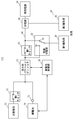
- FIG. 1 is a diagram schematically showing a power distribution system 100 according to Embodiment 1 of the present invention.
- the power distribution system 100 includes a solar battery 10, a storage battery 14, a commercial power supply 24, a bidirectional power conditioner 16, a storage battery control unit 18, a load 26, a first switch 20, A second switch 12, a power source selection unit 22, a power distribution path 66, a distribution board 68, and a storage battery power detection unit 70 are included.
- the solar battery 10 is described as an example of a renewable energy power generator.
- the renewable energy power generator is not limited to the solar battery 10, and may be a wind power generator, for example. May coexist.
- the commercial power source 24 is an AC power source for supplying power from an electric power company.
- the solar cell 10 is a power generator that directly converts light energy into electric power using the photovoltaic effect.
- the distribution board 68 is connected to the commercial power supply 24 at one end and connected to the bidirectional power conditioner 16 at the other end.
- the distribution board 68 receives AC power from one end side or the other end side, and supplies AC power to the second type load 30 described later.
- the distribution board 68 can also measure AC power received from one end side and the other end side.
- the bidirectional power conditioner 16 is connected to the storage battery 14 and the solar battery 10 at one end, and can be connected to the commercial power source 24 via the distribution board 68 at the other end.
- the bidirectional power conditioner 16 includes a bidirectional inverter.
- the inverter converts DC power generated by the solar battery 10 or discharged from the storage battery 14 into AC power, and commercial power. This is a bidirectional inverter that converts AC power from the power source 24 into DC power.
- the storage battery 14 is a secondary battery that can be used repeatedly by accumulating electricity so that it can be used as a battery.
- the storage battery 14 is realized by, for example, a lithium ion secondary battery.
- the storage battery 14 is charged with the electric power of the commercial power supply 24 converted into DC power by the bidirectional power conditioner 16.
- the storage battery 14 may also be charged by electric power generated by the solar battery 10 that is a renewable energy source.
- the storage battery control unit 18 measures various physical quantities of the storage battery 14 such as the storage amount and temperature of the storage battery 14 and provides the specified physical quantities to the bidirectional power conditioner 16.
- the storage battery control unit 18 also performs control such as controlling the heater for warming the storage battery 14 to warm the storage battery 14 or controlling the fan for cooling the storage battery 14 to cool the storage battery 14.
- the storage battery power detection unit 70 measures the power for charging the storage battery 14 and the power discharged by the storage battery 14.
- the storage battery control unit 18 also acquires the measurement result of the storage battery power detection unit 70.
- the second switch 12 is turned on or off between the output terminal of the solar battery 10 and the input terminal of the storage battery 14 and the bidirectional power conditioner 16 in order to prevent the storage battery 14 from being overcharged. Is provided to do. Details of the operation of the second switch 12 will be described later.
- the first switch 20 is provided between the bidirectional power conditioner 16 and the commercial power supply 24, and turns on or off between the bidirectional power conditioner 16 and the commercial power supply 24.
- the power source selection unit 22 has a first terminal 58 connected to the first path branched from between the first switch 20 and the bidirectional power conditioner 16, and a power distribution path between the commercial power source 24 and the first switch 20.
- One of the second terminals 60 connected to the second path branched from 66 is selected for connection to the first type load 28 described later.
- the load 26 further includes a first type load 28 and a second type load 30. Both the first type load 28 and the second type load 30 are AC drive type electric devices that are driven by AC power.
- the second type load 30 is driven by electric power from the power distribution path 66 that connects the commercial power supply 24 and the first switch 20.
- the power supplied from the power distribution path 66 is basically power supplied from the commercial power supply 24 via the distribution board 68.
- the power is supplied from the storage battery 14 via the bidirectional power conditioner 16.
- the generated power is mixed.
- the power generated by the solar cell 10 at the time of peak shift is mixed into the power distribution path 66. Further, even when the peak shift is not performed, the power generated by the solar cell 10 may be mixed into the power distribution path 66.
- the first type load 28 is an electric device that should be driven even when the commercial power supply 24 is interrupted and the power supply is stopped, and power may be supplied without going through the power distribution path 66.
- the first type load 28 is supplied with power from the solar battery 10 or the storage battery 14 via the bidirectional power conditioner 16, but is not supplied with power from the commercial power supply 24.
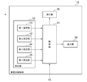
- FIG. 2 is a diagram schematically showing the internal configuration of the storage battery control unit 18 according to the embodiment of the present invention.
- the storage battery control unit 18 includes a setting unit 32, a control unit 34, an instruction unit 36, and a display unit 38.
- the setting unit 32 inputs a charging / discharging pattern including information on a charging time zone for charging the power of the commercial power supply 24 to the storage battery 14 and a discharging time zone for discharging the storage battery 14. Therefore, the setting unit 32 further includes a first setting unit 40, a second setting unit 42, a third setting unit 44, and a fourth setting unit 46.
- the first setting unit 40 is a power storage capacity input unit that is secured during a power failure and inputs a power storage capacity secured during a power failure that the storage battery 14 should secure in preparation for the case where the power supply of the commercial power supply 24 is stopped.
- the 2nd setting part 42 is a discharge time zone input part which inputs the discharge time zone made to discharge to the storage battery 14 for a peak shift.
- the third setting unit 44 is a charging time zone input unit that inputs a charging time zone for charging the power of the commercial power supply 24 to the storage battery 14.
- the fourth setting unit 46 is a discharge amount input unit that inputs a discharge amount permitting the storage battery 14 to discharge over the discharge time period input in the second setting unit 42.
- the display unit 38 is configured by, for example, an LCD (Liquid Crystal Display) panel, and a user of the storage battery control unit 18 (hereinafter, simply referred to as “user”) refers to information displayed on the display unit 38. Enter the discharge time zone and discharge amount. Details of the discharge time zone and the input of the discharge amount by the second setting unit 42 and the fourth setting unit 46 will be described later.
- the term “amount” is used for the electric power stored in or discharged from the storage battery 14 such as “amount of stored electricity” and “amount of discharge”. Further, the term “capacity” is used for the electric power stored in the storage battery 14 like “storage capacity”.
- the control unit 34 obtains the power storage capacity at the time of power failure input by the first setting unit 40 and the total amount of power to be discharged to the storage battery 14 input by the fourth setting unit 46 during the charging time period input by the second setting unit 42. Originally, the amount of stored power to be charged in the storage battery 14 is acquired in the charging time zone input by the third setting unit 44. Thereby, the control part 34 sets the charging / discharging pattern for making the storage battery 14 charge / discharge, and stores it in the memory (not shown) in the control part 34. FIG.
- control unit 34 includes a storage capacity secured during a power failure acquired by the first setting unit 40, a total amount of power to be discharged to the storage battery 14 in a discharge time zone input by the second setting unit 42, and a DC power source. Based on the conversion efficiency at the time of converting the battery into an AC power supply, the amount of power to be charged in the storage battery 14 in the charging time zone input by the third setting unit 44 is acquired.
- the instruction unit 36 instructs charging / discharging of the storage battery 14 according to the set charging / discharging pattern.
- FIG. 3 is a diagram for explaining the amount of electricity stored in the storage battery 14 during the charging time period.
- AC power is converted into DC power, and an AC / DC conversion loss occurs during this conversion.
- direct-current power is converted into alternating current power,
- DC / AC conversion loss also arises in this conversion.
- the storage capacity at the time of power failure input by the first setting unit 40 is P F
- the total amount of power to be discharged to the storage battery 14 during the discharge time period input by the second setting unit 42, that is, the peak shift storage capacity is P S
- the proportion of the AC / DC conversion loss and R AD is P S .
- the AC / DC conversion loss R AD represents the magnitude of AC power converted when the DC power discharged from the storage battery 14 is 1. Therefore, 0 ⁇ R AD ⁇ 1.
- the power storage amount P m that the instructing unit 36 charges the storage battery 14 in the charging time zone input by the third setting unit 44 is: P m ⁇ (P F + P S ) / R AD (1) It becomes.
- the condition for establishing the equal sign is when the storage battery 14 is charged from an empty state.
- power storage allowance P M is previously determined as the upper limit of the electricity storage possible power. Accordingly, the control unit 34 when the electricity storage amount P m obtained using Equation (1) exceeds the power storage allowance P M, the power storage allowance PM and the power storage capacity Pm.
- the maximum allowable voltage of the storage battery, charge / discharge characteristics, etc. are taken into consideration, and may be determined by experiment or based on the rated capacity of the storage battery specified in advance, for example, 15 kWh.
- the power failure ensures storage capacity P F
- the commercial power supply 24 is a power storage capacity to the storage battery 14 is set aside in case of a power outage
- the storage battery 14 so long as the commercial power supply 24 is not a power outage ensure power failure the storage capacity P F is the minimum power storage.
- the AC power P 2 to be supplied to the load 26, P 2 P S ⁇ R DA It becomes.
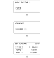
- FIG. 4 is a diagram illustrating an example of an input screen for a charge / discharge time zone and a discharge amount by each unit in the setting unit 32.
- the display unit 38 of the storage battery control unit 18 is a display panel capable of displaying, for example, 20 characters ⁇ 4 lines of ASCII characters. Even in such a limited display area, In order to cope with peak shifts that are as effective as possible according to the purpose of use, power consumption patterns, and the like, which are different for each user, various peak shift settings can be made with a small number of setting items.
- the user operates an operation key (not shown) including up / down / left / right and a determination key provided in the storage battery control unit 18 to input or update information necessary for setting.
- FIG. 4A shows the “current” for inputting whether to delete the charge / discharge pattern of the storage battery 14 and clear the setting item stored in the storage unit (not shown) of the storage battery control unit 18. It is a figure which shows an example of a setting clear selection screen. The user operates the up and down keys to select “Yes” or “No”, and inputs a decision as to whether or not to clear the setting item with the decision key.
- FIG. 4 (b) is a diagram showing an example of a screen power supply of the commercial power supply 24 to set the power failure secure storage capacity P F to be secured to the battery 14 in case of stopping.
- the power storage allowance P M of the storage battery 14 in the embodiment is 15 kWh, the user is able to set a value, for example 1kWh increments of between 5kWh to 14KWh.
- FIG. 4C is a diagram showing an example of a screen for setting a discharge time zone and a discharge amount.
- the discharge time zone input in the second setting unit 42 is divided at predetermined time intervals.
- the “predetermined time interval” is a discharge amount setting reference interval that is divided in order to enable various peak shift settings, and may be determined experimentally in consideration of an assumed peak shift setting and the like. Is, for example, one hour interval.
- the display unit 38 displays a setting screen for one discharge amount setting reference interval on one screen. Since the discharge time zone and the discharge amount are set in units of one day, when the discharge amount setting reference interval is 1 hour, the display unit 38 displays 24 screens for 24 hours.
- FIG. 4C illustrates a screen for setting the charge / discharge amount at 21:00.
- the user can input power to be discharged to the storage battery 14 by 0.5 kWh by operating the left and right keys.
- the display unit 38 displays “CHARGE” and does not display a specific numerical value of the charged amount. This is because the specific charged amount is determined by the above equation (2).
- the storage battery 14 is assumed to have a product life in a charge / discharge cycle. Therefore, for example, if the setting of repeating charging and discharging many times within one day is allowed, the life cycle of the storage battery 14 may be shortened. Therefore, the charging may not be selected except for one set period within a predetermined period, and the setting from 23:00 to 0:00 on the next day is also possible.
- the “predetermined one period” is a period serving as a reference unit for determining whether or not to allow the storage battery 14 to be charged, and may be determined by experiment according to the type of the storage battery 14 or the like. For example, 24 hours.
- the third setting unit 44 inputs one continuous period of 24 hours as a charging time zone.
- the charging / discharging cycle of the storage battery 14 is restricted, and it is possible to suppress the consumption of the storage battery 14 before reaching the lifetime assumed for the storage battery 14 at the time of design.
- charging of the storage battery 14 is limited to once per day (24 hours), even if the discharge is divided into a plurality of time zones, the total charge / discharge amount per day does not change, so the life is not affected. Therefore, it becomes possible to set the time zone finely according to fluctuations in demand.
- the control unit 34 also displays on the display unit 38 the discharge amount PT that can be used for the daily peak shift.
- the discharge amount PT that can be used for the daily peak shift is shown as “TOTAL”.
- available peak shifts daily discharge amount P T is the difference P M -P F power storage allowance P M and the power failure secure storage capacity P F.
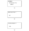
- FIG. 5 is a diagram showing another example of a charging / discharging time zone and discharge amount input screen of the storage battery 14 by each unit in the setting unit 32.
- FIG. 5A is a diagram illustrating an example of a notification screen when the setting of the charge / discharge pattern of the storage battery 14 is incomplete. Inadequate setting of the charge / discharge pattern is, for example, when there is no setting for discharging despite the setting for charging the storage battery 14, or when there is no setting for charging despite the setting for discharging the storage battery 14. In the case where the above-mentioned P REST is a negative value, the storage battery 14 is charged for a short period (for example, 1 hour).
- FIG. 5A illustrates a screen for notifying a warning when there is no setting for discharging the storage battery 14 despite the setting for charging the storage battery 14.
- the user can reset the charge / discharge pattern by operating the up / down keys or can maintain the setting as it is.
- FIG. 5B is a diagram showing an example of a screen for confirming whether or not the setting of the charge / discharge pattern of the storage battery 14 is reflected. The user can select and decide whether to reflect the setting of the charge / discharge pattern with the up and down keys.
- FIG.5 (c) is a figure which shows the example of the screen which confirms whether the storage battery control part 18 is restarted.
- the charge / discharge pattern of the storage battery 14 is reflected after the storage battery control unit 18 is restarted. Therefore, in order to reflect the change of the charge / discharge pattern of the storage battery 14 at the end of the transition of the charge / discharge pattern setting screen, the display unit 38 displays a screen for informing the user to restart the storage battery control unit 18. The user can select and decide whether or not to restart the storage battery control unit 18 with the up and down keys.
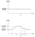
- FIG. 6 is a diagram illustrating an example of fluctuation of the storage capacity of the storage battery 14 in one day.
- the power distribution system 100 connects the solar cell 10 in parallel with the commercial power source 24, supplies power from both the commercial power source 24 and the solar cell 10 to the load 26, and stores the storage battery 14. It is a charging system.
- FIG. 6A shows the storage capacity of the storage battery 14 when the storage battery 14 is not discharged for peak shift and the bidirectional power conditioner 16 is operated as a pseudo conventional solar battery power conditioner. It is a figure which illustrates the fluctuation
- FIG. 6B is a diagram illustrating the variation in the storage capacity of the storage battery 14 when the storage battery 14 is discharged for peak shift.
- a time T 1 is the charge starting time, time T 2, is the charging finishing time. Therefore, a period from time T 1 to time T 2 is a charging time zone input to the third setting unit 44.
- a period from time T 3 to time T 4 and a period from time T 5 to time T 6 are discharge time zones input by the second setting unit 42. Since the control unit 34 causes the storage battery to discharge for peak shift in the discharge time zone, the storage capacity of the storage battery 14 gradually decreases. At the time T 4 is the end time of the discharge time zone, power storage capacity of the storage battery 14 is reduced at the time to ensure storage capacity P F power outage.
- the control unit 34 In the case where the storage battery 14 in the discharge time period the power storage capacity of the storage battery 14 has reached the power outage secure storage capacity P F during the discharge, that is, when the time of securing storage capacity P F discharge time period and a power failure, the control unit 34, Even during the discharge time period set by the second setting unit 42, the discharge of the storage battery 14 is stopped, and a warning that the storage battery control unit 18 is in an abnormal state is notified to the bidirectional power conditioner 16.
- the bi-directional power conditioner 16 is also provided with an LCD panel (not shown), and displays in a different manner from usual, for example, the backlight lights up red.
- the controller 34 ends the abnormality notification to the bidirectional power conditioner 16 and the abnormal state is released.
- the controller 34 charges the storage battery 14 after the start of the next charging time zone.
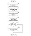
- FIG. 7 is a flowchart for explaining the processing flow of the storage battery control unit 18 according to the embodiment of the present invention.
- the process in this flowchart is started when the user sets the charge / discharge pattern of the storage battery 14 using the setting unit 32, for example.
- the first setting unit 40 inputs a power failure secure storage capacity P F (S2).
- the 2nd setting part 42 inputs the discharge time slot
- a discharge amount is input (S4).
- the 3rd setting part 44 inputs the charge time slot
- Control unit 34 uses equation (2) above, is obtained by calculating the power storage amount P m to charge the storage battery 14 (S8).
- Control unit 34 compares the acquired magnitude relationship between power storage allowance P M of the charged amount P m and the storage battery 14. When the charged amount P m > the allowed storage amount P M (Y in S10), the control unit 34 sets the charged amount P m to the allowed storage amount P M (S12). For storage amount P m ⁇ power storage allowance P M (S10 of N), the control unit 34 sets the calculated storage amount P m as a storage amount P m. When the control unit 34 sets the storage amount P m, processing in this flowchart is terminated.
- FIG. 8 is a flowchart for explaining the flow of the discharge time zone and discharge amount input processing by the second setting unit 42 and the fourth setting unit 46, and is a diagram for explaining the process of step S4 in FIG. 7 in detail.
- the second setting unit 42 sets the initial value of the discharge time zone (S14). When dividing 24 hours a day by the discharge amount setting reference interval every hour, 24 divisions from 0:00 to 23:00 are made. For example, the second setting unit 42 sets 7 o'clock as the initial value of the discharge time zone.
- the 4th setting part 46 acquires and inputs the discharge amount of the storage battery 14 in the discharge amount setting reference
- the control unit 34 displays the remaining capacity PREST of the storage battery 14 calculated using the above formula (3) on the display unit 38 (S18).
- the second setting unit 42 updates the time zone in which the discharge amount is set (S22), and returns to the process of step S16.
- the control unit 34 displays a confirmation notification that prompts the user to restart the storage battery control unit 18 (S24), and the processing in this flowchart is as follows. finish.
- control unit 34 sets a charge / discharge pattern for charging / discharging the storage battery 14, but at this time, the control unit 34 performs constant current charging until the voltage of the storage battery 14 reaches a predetermined upper limit voltage, When the voltage of the storage battery 14 reaches a predetermined upper limit voltage, switching from constant current charging to constant voltage charging is performed, and a charging pattern for fully charging the storage battery 14 is also set by executing constant voltage charging as supplementary charging. To do.
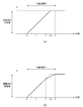
- FIG. 9 is a diagram for explaining the charge rate RC setting of the storage battery 14.
- FIG. 9A shows a case where the charging time period is 3 hours, and the constant current charging is performed when the electric power supplied from the commercial power supply 24 for charging the storage battery 14 and stored in the storage battery 14 is P 1. It is a figure which shows the case where the charge rate of the storage battery 14 is set so that charge may be completed 30 minutes before the end time of a charge time slot
- the “charge rate R c ” of the storage battery 14 is a charge amount per unit time supplied to the storage battery 14.
- the charging time T C to devote time to charge the storage battery 14 the charging rate R C is calculated by the following equation (4).
- R C P 1 / T C (4)
- the control unit 34 If the current storage capacity of the storage battery 14 is sufficiently smaller than the power storage allowable amount P M, the control unit 34 is charged with a constant current charging. On the other hand, if the storage capacity of the storage battery 14 is close to the storage allowance P M by the power storage to the storage battery 14, from the viewpoint of protection of the storage battery 14, the control unit 34 switches to the constant voltage charging.
- the constant voltage charge may be switched to a constant voltage charge after a predetermined time has elapsed since the start of the constant current charge. However, after the constant current charge is started, the voltage of the storage battery 14 is determined according to the type of the storage battery 14. When the voltage is reached, it may be switched to constant voltage charging.
- the “predetermined upper limit voltage” is a charge switching reference voltage that is a determination reference for switching from constant current charging to constant voltage charging when the storage battery 14 is charged.
- the initial value of the predetermined upper limit voltage may be determined by experiment according to the type of the storage battery 14.
- FIG. 9B is a diagram illustrating a case where constant voltage charging is performed after the storage battery 14 is subjected to constant current charging.
- the length of the charging time zone is 3 hours, and the power supplied from the commercial power supply 24 to charge the storage battery 14 is it is a P 1.
- FIG. 9B shows that the control unit 34 switches to the constant voltage charging because the storage capacity of the storage battery 14 has reached a predetermined upper limit voltage at the time of 2 hours after starting the charging of the storage battery 14, and as a result, the end time of the charging time zone. It shows that charging is not completed even 30 minutes before. In this case, the control unit 34 continues to charge the storage battery 14 until the end time of the charging time zone.
- the control unit 34 acquires the temperature of the storage battery 14, and charges the time actually charged for the storage battery 14 according to the acquired temperature before the charging time T C , that is, the end time of the charging time zone. It is preferable to change whether the charging rate RC is changed. Specific setting value of the charging time T C in response to the temperature of the battery 14 may be determined by experimentation in light of the nature of the battery 14.
- control unit 34 determines the charging rate Rc at the constant current charging so that the charging is completed 30 minutes before the end time of the charging time zone in preparation for performing the constant voltage charging. Thereby, in the second half of the charging of the storage battery 14, even if constant voltage charging that takes longer time to charge than in the case of constant current charging is performed, charging can be completed while reducing the burden on the storage battery 14. it can.
- the storage battery 14 stores the reserved power storage capacity at the time of power failure that should be secured in preparation for when the power supply of the commercial power supply 24 is stopped, and the peak shift storage capacity to be used for peak shift.
- the secured storage capacity at the time of a power failure is used in the event of an emergency such as when the commercial power supply 24 is at a power failure. Therefore, the secured storage capacity at the time of a power failure is always stored in the storage battery 14 during normal times. Therefore, when the storage battery 14 is charged, the storage capacity of the storage battery 14 is close to the allowable storage capacity when the peak shift storage capacity is charged. Therefore, in order to charge the peak shift storage capacity, the control unit 34 uses a charging pattern for performing constant voltage charging after performing the above-described constant current charging.
- the storage capacity secured during a power failure should be stored in the storage battery 14 as soon as possible, and the performance of the storage battery 14 and the power conditioner is independent of the method for determining the charge rate for charging the peak shift storage capacity. Constant current charging is performed using the maximum charging rate allowed by the above. However, even when charging the secured storage capacity at the time of a power failure, depending on the setting method, it may be assumed that the peak shift capacity is reduced and the secured storage capacity at the time of a power failure is charged to near full charge. In such a case, charging may be performed up to the voltage range of constant voltage charging.
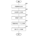
- FIG. 10 is a flowchart for explaining the flow of the charging rate setting process of the storage battery 14 in the charging time zone, which is performed in the control unit 34 according to the embodiment of the present invention.
- the processing in this flowchart starts after each unit in the setting unit 32 acquires a charge / discharge pattern input from the user.
- the control unit 34 From the charge / discharge time zone and the discharge amount input at each unit in the setting unit 32, the control unit 34 obtains a charge time zone to be stored in the storage battery 14 (S26). The control unit 34 secures a predetermined auxiliary charging time zone for performing auxiliary charging, and then calculates the remaining time zone length for charging time T for calculating the constant current charging rate of the storage battery 14. Obtained as C (S28). The control unit 34 charges the storage battery 14 on the basis of the reserved storage capacity at the time of a power failure, the total amount of power discharged to the storage battery 14 during the discharge time period, and the conversion efficiency when converting the DC power supply to the AC power supply. obtaining the amount P 1 (S30).
- Control unit 34 obtains by calculating the charge rate R C and a charging time T C storage amount P 1 Tokyo (S32). As described above, the control unit 34 sets the charging pattern of the storage battery 14 illustrated in FIG. 9 (S34). When the control unit 34 sets the charging pattern of the storage battery 14, the processing in this flowchart ends.
- the control unit 34 in the storage battery control unit 18 sets the charging pattern has been described.
- the upper limit value of the charging voltage of the storage battery 14 can also be set in the bidirectional power conditioner 16. Good. Note that power in the direction from the commercial power supply 24 to the storage battery 14 is a negative number, and power in the direction from the storage battery 14 to the commercial power supply 24 is a positive number.
- the charging power becomes a negative value.
- the bidirectional power conditioner 16 changes the charging power stepwise to the + side regardless of an instruction from the control unit 34. That is, the bidirectional power conditioner 16 gradually reduces the charging power. Thereby, the charging current of the storage battery 14 gradually decreases, and constant voltage charging can be realized.
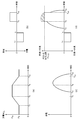
- FIG. 11 is a diagram for explaining the relationship between peak shift and charge / discharge according to the embodiment of the present invention.
- FIG. 11A is a diagram illustrating a change in the daily storage capacity of the storage battery 14 due to the charge / discharge pattern input to the setting unit 32.
- time T 7 is the charging start time
- time T 8 is the charging end time. Therefore, the period from the time T 7 up to the time T 8 becomes the charging time period is a charging duration.
- the time T 9 are discharge start time
- the time T 10 is the discharge end time.
- Period from time T 9 up to the time T 10 is the discharge time period is the discharge duration.
- FIG. 11 (b) is a diagram showing a time zone during which the storage battery 14 is charged or discharged, and its power.
- the positive direction on the vertical axis represents the discharge amount of the storage battery 14, and the negative direction represents the charge amount.
- FIG. 11C is a diagram illustrating an example of fluctuations in the power generation amount of the solar cell 10.
- Power generation of the solar cell 10 to the time T 12 later than the time T 10 is the end time of the discharge time zone of the storage battery 14 continues.
- FIG. 11 (d) is a diagram showing the daily time variation of the power output from the bidirectional power conditioner 16.
- the bidirectional power conditioner 16 is connected to the storage battery 14 and the solar battery 10. Therefore, when the discharge time zone is set at daytime, the output of the bidirectional power conditioner 16 is the sum of the discharge amount from the storage battery 14 and the power generation amount of the solar battery 10.
- the upper limit value P PCS is set for the output of the bidirectional power conditioner 16, and power larger than the upper limit value P PCS cannot be output.
- the output upper limit value P PCS is set to 10 kWh, but the specific value of the output upper limit value P PCS is not limited to this.
- the discharge of the storage battery 14 is started at the start time T 9 of the discharge time zone of the storage battery, the power generation amount total bidirectional power of the discharge amount and the solar cell 10 from the storage battery 14 It may occur when the output upper limit value P PCS of the conditioner 16 is exceeded.
- FIG. 11 (d) This state indicates a case where continued until the start time T 10 of the discharge time zone of the storage battery. In this case, minute power exceeding the output upper limit value P PCS of the bidirectional power conditioner 16 indicated by hatching shown in FIG. 11 (d) is not outputted, so that the remaining storage capacity of the storage battery 14 as a result of .
- the power consumption of the load 26 may become the output upper limit value of the bidirectional power conditioner 16 so that the power output from the bidirectional power conditioner 16 does not flow backward to the commercial power supply 24.
- the smaller one of the power consumption of the load 26 and the output upper limit value P PCS of the bidirectional power conditioner 16 becomes the output upper limit value of the bidirectional power conditioner 16.
- the control unit 34 controls charging / discharging of the storage battery 14 according to the charging / discharging pattern
- the storage capacity of the storage battery 14 is larger than the reserved storage capacity at the time of power failure by the end of the discharge time period included in the charging / discharging pattern.
- the charging / discharging of the storage battery 14 is controlled with a temporary pattern different from the charging / discharging pattern set by the setting unit 32.
- the control unit 34 causes the storage battery 14 to discharge even when it is not in the discharge time zone in the charge / discharge pattern set by the setting unit 32, or by adjusting the charge amount at the next charge, etc. Then, the amount of charge / discharge of the storage battery 14 is changed so as to return to the control by the normal charge / discharge pattern as soon as possible.
- the control unit 34 when the storage capacity of the storage battery 14 is larger than the reserved storage capacity at the time of power failure at the end of the discharge time period included in the charge / discharge pattern set by the setting unit 32, the discharge time period You may make the storage battery 14 discharge after completion
- the control unit 34 performs the next charging when the storage capacity of the storage battery 14 is larger than the reserved storage capacity at the time of power failure at the end of the discharge time period included in the charge / discharge pattern set by the setting unit 32.
- the storage battery 14 may be charged less by the difference between the storage capacity of the storage battery 14 and the storage capacity ensured during a power failure in the time zone.
- the storage capacity of the storage battery 14 is charged up to the charging capacity for peak shift after the end of the next charging time zone. Can return to normal charge / discharge pattern control.
- the control unit 34 estimates that the storage capacity of the storage battery 14 is larger than the reserved storage capacity at the time of power failure at the end of the discharge time period included in the charge / discharge pattern set by the setting unit 32. In this case, electric power that is equal to or higher than the discharge capacity by the charge / discharge pattern set by the setting unit 32 may be discharged in the discharge time zone.
- the setting unit 32 also allows setting of a charge / discharge pattern that discharges a discharge amount that exceeds the discharge amount PT that can be used for the daily peak shift. If surplus power is generated from the initial schedule, the control unit 34 discharges the storage battery 14 according to a charge / discharge pattern that discharges a discharge amount that exceeds the discharge amount PT that can be used for the peak shift of the day. You may make it make it.
- the control unit 34 estimates that the storage capacity of the storage battery 14 is larger than the reserved storage capacity at the time of power failure at the end of the discharge time period included in the charge / discharge pattern set by the setting unit 32.
- power may be consumed by a load for consuming power during the discharge time period.
- the load for consuming electric power is, for example, a surplus power remaining in the storage battery 14 such as a heater (not shown) for heating the storage battery 14 or a fan (not shown) for cooling the storage battery 14. It is a load for consuming the expected power.
- the control unit 34 refers to the history of power consumed by the load 26 in the discharge time zone in the past, acquires the total amount of power consumption in the discharge time zone, and assumes that the acquired total amount has been consumed.
- the storage capacity of the storage battery 14 is compared with the reserved storage capacity during a power failure. As a result of the comparison, when the storage capacity of the storage battery 14 is greater than the storage capacity secured during a power failure, the control unit 34 determines that the storage capacity of the storage battery 14 is at the end of the discharge time period included in the charge / discharge pattern set by the setting unit 32. Estimated to be larger than the reserved storage capacity at the time of power failure.
- FIG. 12 is a diagram illustrating an example of a time variation pattern of power consumption in the load 26.
- FIG. 12 is a graph with time on the horizontal axis and power consumption of the load 26 at each time on the vertical axis.
- the power fluctuation time variation pattern of the load 26 may be stored in a storage unit (not shown) in the control unit 34.
- control unit 34 determines whether or not power can be consumed until the storage capacity of the storage battery 14 reaches the reserved storage capacity at the time of a power failure in the discharge time zone. Power to the load for consuming power. As a result, the storage capacity of the storage battery 14 becomes the reserved storage capacity at the time of power failure after the end of the discharge time zone, so that the control unit 34 can return to the normal charge / discharge pattern control after the end of the charge time zone.
- FIG. 13 is a flowchart for explaining the flow of charge / discharge processing at the time of peak shift of the control unit 34 according to the embodiment of the present invention.
- the processing in this flowchart starts after each unit in the setting unit 32 acquires a charge / discharge pattern input from the user.
- the control unit 34 sets the charge / discharge pattern of the storage battery 14 from the information on the charge / discharge pattern acquired by each unit in the setting unit 32 (S36).
- the controller 34 checks the storage capacity of the storage battery 14 at the end of the discharge time period included in the charge / discharge pattern (S38). When the storage capacity of the storage battery 14 at the end of the discharge time zone is larger than the reserved storage capacity at the time of power failure (Y in S40), the control unit 34 temporarily sets a temporary discharge pattern instead of the set charge / discharge pattern. (S42). When the storage capacity of the storage battery 14 at the end of the discharge time period is less than the reserved storage capacity at the time of power failure (N in S40), the control unit 34 maintains the original charge / discharge pattern without setting the temporary discharge pattern. .
- the charge / discharge pattern of the storage battery 14 is reflected after the storage battery control unit 18 is restarted. Until the storage battery control unit 18 is restarted, the charge / discharge pattern before the setting change is maintained.
- the storage capacity secured at the time of power failure should be secured by the storage battery 14 in case the power supply of the commercial power supply 24 is stopped. Therefore, when the storage battery control unit 18 is restarted after the value of the reserved storage capacity at the time of a power failure is changed and the setting change is reflected, the control unit 34 has the changed new input to the first setting unit 40 It is compared whether or not the storage capacity secured during a power failure is larger than the storage capacity of the storage battery 14. When the storage capacity secured at the time of the power failure after the change is larger than the storage capacity of the storage battery 14, the control unit 34 secures at the time of the power failure after the change regardless of whether or not it is the charging time zone input by the third setting unit 44. The storage battery 14 is charged until the storage capacity is reached.
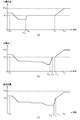
- FIG. 14 is a diagram illustrating the change in the storage capacity of the storage battery 14 before and after the setting change of the charge / discharge pattern.
- the control unit 34 starts charging the storage battery 14. Thereafter, at time T 14, the power storage capacity of the storage battery 14 reaches the increased power outage secure storage capacity P F after change 'from power failure secure storage capacity P F before the change.
- Control unit 34 is to charge the storage battery 14 during the period from time T 13 until the time T 14, this period regardless of whether a charging time period for peak shift contained in the charge-discharge pattern This is the charging period to be executed.
- the control unit 34 When the storage battery 14 is set not to discharge for peak shift, the control unit 34 returns to normal control when the storage capacity P F ′ at the time of power failure after the change is reached.
- the control unit 34 sets the peak shift for the storage battery 14 when the start time of the first charging time zone is reached after reaching the storage capacity P F ′ secured at the time of power failure after the change. Start charging.
- the controller 34 does not charge / discharge the storage battery 14 until the start time of the charging start time zone is reached after reaching the secured storage capacity P F ′ at the time of the power failure after the change. For this reason, it is preferable to restart the storage battery control unit 18 at a time sufficiently before the charge start time after the setting change, for example, two hours before the charge start time after the charge / discharge pattern setting change.
- FIG. 15 is a diagram illustrating another example of the variation in the storage capacity of the storage battery 14 before and after the setting change of the charge / discharge pattern, and illustrates the variation in the storage capacity during charging for peak shift.
- FIG. 15A is a diagram illustrating an example in a case where the storage battery control unit 18 is restarted at a time sufficiently before the start time of the charge start time zone, and the setting change of the charge / discharge pattern becomes effective. .
- time T 15 is the time when the user changes the setting of the charge / discharge pattern
- time T 19 and time T 20 are included in the charge / discharge pattern after the setting change, respectively. It represents the start time and end time of the charging time zone.
- the battery control unit 18 at time T 13 is the restart to charge and discharge pattern setting changes become effective, the control unit 34 immediately starts charging the storage battery 14, at time T 14 of the battery 14
- the storage capacity has reached the reserved storage capacity P F ′ at the time of power failure after the change.
- the control unit 34 controls the charging and discharging of the storage battery 14 in accordance with charge and discharge pattern before change.
- FIG. 15 (a) reaches a power outage secure power storage after storage capacity is changed capacity P F of the storage battery 14 'at time T 14 before the T 16 is the starting time of the charging start time zone , the period from time T 14 until the time T 16 the control unit 34 does not perform the charging and discharging of the storage battery 14. Accordingly, the period from time T 14 until the time T 16 is a power storage capacity of the storage battery 14 is kept at secure storage capacity P F 'after the change power failure. Becomes a T 16 is the starting time of the charging start time period, the control unit 34 starts charging the storage battery 14, the power storage capacity of the storage battery 14 at time T 17 reaches the storage capacity P m after the change '.
- FIG. 15B also shows another example in the case where the storage battery control unit 18 is restarted at a time sufficiently before the start time of the charge start time zone, and the setting change of the charge / discharge pattern becomes effective. It is.
- the control unit 34 Charge / discharge of the storage battery 14 is controlled according to the charge / discharge pattern before the change.
- the control unit 34 starts charging the storage battery 14, power failure after the power storage capacity of the storage battery 14 is changed ensure power storage at the time T 19 volume reached P F ' did. Since the time T 19 is earlier than the charging start time T 16, the period from time T 19 until the time T 16, the storage capacity of the storage battery 14 is kept at secure storage capacity P F 'after the change blackout It is.
- FIG. 15C is a diagram showing another example in the case where the storage battery control unit 18 is restarted immediately before the start time of the charge start time zone, and the setting change of the charge / discharge pattern becomes valid.
- the control unit 34 immediately storage battery 14 Although starts charging, power storage capacity of the storage battery 14 at the time of charging start time T 16 is 'not reach, when secured storage capacity P F blackout' power failure secure storage capacity P F after the change is below.
- the control unit 34 continues the charging of the battery 14 up to the end time T 17 of the charging time period. When it becomes the end time T 17 of the charging time period, even if the storage capacity of the storage battery 14 does not reach the storage capacity P m 'after the change, the control unit 34 stops charging of the battery 14.
- the control unit 34 when to be accumulated in the battery 14 when power failure secure storage capacity P F of the changed 'is greater than the power storage capacity of the storage battery 14, the battery 14 in the charging time period at the charging pattern after the change
- the battery may be charged at a charge rate different from that for storing electricity.
- the charge rate from time T 20 until the time T 21 is a high charging rate as compared to the charge rate from time T 21 until the time T 17, the unit The amount of charge of the storage battery 14 per hour is large. Therefore, in FIG. 15 (c), the slope of the graph from the time T 20 until the time T 21 is greater than the slope of the graph from time T 21 until the time T 17.
- charging is performed at the maximum charge rate allowed for charging as quickly as possible. This is because the charging in the charging time zone after reaching is performed at the rate determined by the charging rate determination method in the normal charging time zone.
- FIG. 16 is a flowchart for explaining the flow of processing after changing the charge / discharge pattern setting of the control unit 34 according to the embodiment of the present invention.
- the process in this flowchart starts after the storage battery control unit 18 is restarted after the charge / discharge pattern setting is changed.
- the control unit 34 acquires the storage capacity P F ′ secured at the time of power failure after the change newly input to the first setting unit 40 (S44). The control unit 34 also acquires the changed charging time zone newly input to the third setting unit 44 (S46).
- Control unit 34 obtains the current storage capacity P C of the storage battery 14 (S48). If power failure secure storage capacity P F of the changed 'is greater than the current charge capacity P C of the storage battery 14 (S50 of Y), the control unit 34, the current time is newly input to the third setting portion 44 Regardless of whether or not it is the changed charging time zone, the storage battery 14 is charged until reaching the reserved storage capacity P F ′ at the time of the power failure after the change (S52). If power failure secure storage capacity P F after the change 'is less than or equal to the current storage capacity P C of the storage battery 14 (S50 of N), the control unit 34 does not any particular process.
- the control unit 34 may notify the user of the restart timing of the storage battery control unit 18.
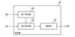
- FIG. 17 is a diagram schematically illustrating a restart timing notification function configuration of the control unit 34 according to the embodiment.
- the control unit 34 further includes a first calculation unit 48, a second calculation unit 50, and a notification unit 52.
- the first calculation unit 48 charges the storage battery 14 to the reserved storage capacity at the time of power failure when the changed storage capacity after the change newly input to the first setting unit 40 is larger than the current storage capacity of the storage battery 14.
- the charge time required for this is calculated.
- the first calculation unit 48 performs charging required for charging by dividing the difference between the storage capacity secured during a power failure and the current storage capacity by the charge rate for charging the secured storage capacity during the power failure. Calculate time.
- the first calculation unit 48 determines the storage capacity that is expected immediately before the charge start time in the charge / discharge pattern before the change, that is, the setting.
- the charging time may be calculated from the difference between the storage capacity substantially equal to the storage capacity secured at the time of the power failure before the change and the storage capacity secured at the time of the power failure after the change.
- the second calculation unit 50 calculates the time at which charging should be started in order to charge the storage battery 14 to the changed storage capacity at the time of power failure. More specifically, the time before the charging time calculated by the first calculation unit 48 from the start time of the charging time zone input by the third setting unit 44 is calculated. The time calculated by the second calculation unit 50 is a charging start time necessary for starting charging of the storage battery 14 in order to make the storage capacity of the storage battery 14 reach the reserved storage capacity during a power failure. If the charging is not started before the charging start time at the latest, the storage capacity of the storage battery 14 does not reach the reserved storage capacity at the time of power failure by the start time of the peak shift charging time zone.
- the notification unit 52 notifies the charging start time calculated by the second calculation unit 50. Specifically, the notification unit 52 causes the display unit 38 to display the charging start time calculated by the second calculation unit 50.
- the notification unit 52 may not only display the charge start time calculated by the second calculation unit 50 on the display unit 38 but also notify the storage battery control device to restart before the charge start time. Thereby, since the user can know the charging start time, it is possible to restart the storage battery control unit 18 with a margin.
- the notification unit 52 causes the display unit 38 to display that a sufficient charging time cannot be secured and the secured storage capacity cannot be charged during a power failure by the start time of the charging time zone.
- the notification unit 52 may further display on the display unit 38 that in this case, the reserved storage capacity at the time of power failure should be reduced.
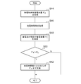
- FIG. 18 is a flowchart for explaining the flow of restart timing notification processing of the storage battery control unit 18 in the control unit 34 according to the embodiment of the present invention.
- the process in this flowchart starts after the storage battery control unit 18 is restarted after the charge / discharge pattern setting is changed.
- step S44 to step S50 is the same as the processing shown in FIG.
- the first calculating section 48 when secured storage capacity P F outage the storage battery 14' during power outages secure storage capacity P F after the change to the The charging time required for charging is calculated (S54). Based on the charging time calculated by the first calculation unit 48, the second calculation unit 50 calculates a time at which charging should be started in order to charge the storage battery 14 up to the changed secured power storage capacity P F ′ at the time of power failure. (S56).
- the notification unit 52 causes the display unit 38 to display the time at which the charging calculated by the second calculation unit 50 should be started (S60).
- the notification unit 52 also displays on the display unit 38 that the storage battery control unit 18 should be restarted by the time calculated by the second calculation unit 50 to start charging (S60).
- the notification unit 52 causes the display unit 38 to the effect to be restarting the battery control unit 18, power failure ensures storage capacity P F after the change 'if the current is less than the power storage capacity P C of the storage battery 14 (S50 of N)
- the processing in this flowchart ends.
- the technique for managing the storage battery connected in parallel with the commercial power supply can be provided.
- control unit 34 is installed in the storage battery control unit 18
- the control unit 34 is not necessarily installed in the storage battery control unit 18.
- the installation location of the control unit 34 is flexible.
- the control unit 34 may be installed in the bidirectional power conditioner 16 or may exist alone.
- the invention according to the present embodiment may be specified by the items described below.
- a first setting unit for inputting a secured storage capacity at the time of a power failure to be secured to the storage battery in preparation for the case where the power supply of the commercial power supply is stopped;
- a second setting unit for inputting a discharge time zone for discharging the storage battery;
- a third setting unit for inputting a charging time zone for charging the storage battery with power from a commercial power source;
- a fourth setting unit for inputting a discharge amount permitting the storage battery to discharge over the discharge time period input in the second setting unit; Based on the total amount of power to be discharged to the storage battery input by the fourth setting unit and the charged storage capacity at the time of power failure input by the first setting unit during the charging time period input by the second setting unit,
- a storage battery control device comprising: a control unit that acquires an amount of electricity to be charged in the storage battery during a charging time period input by the third setting unit.
- Item 3 The storage battery control device according to Item 1-1, wherein the third setting unit inputs one set period as a charging time zone in a predetermined one period.
- the second setting unit divides a time zone for discharging the storage battery into a plurality of time zones within a predetermined one period and inputs the time zone as a discharge time zone, and the fourth setting unit inputs the plurality of time periods.
- Item 3. The storage battery control device according to item 1-1 or 1-2, wherein electric power to be discharged to the storage battery is input for each band.
- the control unit causes the storage battery to discharge to a discharge amount permitted by the fourth setting unit during the discharge time period set by the second setting unit, and the storage capacity of the storage battery is determined by the first setting unit during the discharge time period.
- Items 1-1 to 1 are characterized in that, when the input power storage capacity at the time of power failure is reached, the discharge of the storage battery is stopped and a warning is notified even during the discharge time period set by the second setting unit.
- the storage battery control device according to any one of -4.
- the control unit converts the secured storage capacity at the time of power failure input by the first setting unit, the total amount of power to be discharged to the storage battery during the discharge time period input by the second setting unit, and a DC power source into an AC power source. 7. The method according to any one of Items 1-1 to 1-6, wherein the storage amount to be charged in the storage battery in the charging time period input by the third setting unit is acquired based on the conversion efficiency at the time. Storage battery control device.
- the control unit obtains a total amount of power consumption in the time period with reference to a history of power consumed by the load connected to the control device in the discharge time period in the past, and consumes the acquired total amount. If the storage capacity of the storage battery is greater than the storage capacity secured during a power failure, the storage capacity of the storage battery is greater than the storage capacity secured during a power failure at the end of the discharge time period included in the charge / discharge pattern set by the setting unit.
- Item 6 The power distribution system according to Item 2-5, wherein
- Constant current charging is performed until the voltage of the storage battery reaches a predetermined upper limit voltage.
- a control unit for setting a charging pattern for fully charging the storage battery by executing An instruction unit for charging the storage battery according to a charging pattern set by the control unit, The control unit secures a predetermined supplementary charging time zone for supplementary charging, and then assumes a constant current charging in all the remaining time zones, and then a constant current for completing the charging of the storage battery.
- a storage battery control device that determines a charge rate.
- the control unit includes a peak shift power storage among a power storage capacity secured during a power failure and a peak shift power storage capacity to be used for a peak shift when power supply of a commercial power supply in the storage battery is stopped.
- Item 3 The storage battery control device according to Item 3-1, wherein a charge pattern is used to charge power corresponding to the capacity.
- the control unit is configured to input the charging time zone input by the charging time zone input unit when the changed storage power storage capacity after the power failure newly input to the power storage capacity input unit after the power failure is larger than the storage capacity of the storage battery. Regardless of whether or not, the storage battery control device charges the storage battery up to the storage capacity secured at the time of power failure after the change.
- the control unit starts charging the storage battery before the start time of the charging time zone input by the charging time zone input unit, and the storage capacity of the storage battery is changed when the start time of the charging time zone comes Item 4.
- the storage battery control device according to Item 4-1, wherein the storage battery is continuously charged until the end time of the charging time period when the storage capacity is less than the secured storage capacity during a power failure.
- the control unit inputs the charging time zone when storing the storage battery when the storage capacity after the power failure after the change newly input to the storage capacity input unit after the power failure is larger than the storage capacity of the storage battery. 3.
- the storage battery control device according to item 4-1, or 4-2, wherein the storage battery is charged with a charge amount per unit time different from that when the storage battery is charged in the charging time zone input by the unit.
- the control unit is charged per unit time when the storage battery stores power when the changed storage power storage capacity after a change newly input to the power storage capacity input unit is larger than the storage capacity of the storage battery.
- Any of items 4-1 to 4-3 is characterized in that the amount of charge is set to be equal to or greater than the amount of charge per unit time when the storage battery is charged in the charging time period input by the charging time period input unit.
- the control unit is configured such that a difference between a storage capacity of the storage battery at a start time of a discharge time period input by the discharge time period input unit and a reserved storage capacity at the time of a power failure input by the power storage capacity input unit at a power failure is the discharge 5.
- the storage battery control device according to any one of items 4-1 to 4-4, wherein discharge of the storage battery is started even when the discharge amount is less than that permitted for the storage battery during a time period .
- a power storage capacity input section secured during a power failure for inputting a power storage capacity secured during a power failure to be secured in the storage battery in preparation for the case where the power supply of the commercial power supply is stopped,
- a charging time zone input unit for inputting a charging time zone for charging the power of the commercial power source to the storage battery;
- a control unit for charging the storage battery in a charging time zone input by the charging time zone input unit;
- the controller is When the power storage capacity secured at the time of a power failure after change, which is newly input to the power storage capacity input section at the time of the power failure, is larger than the power storage capacity of the storage battery, the charging time required for charging to the power storage capacity secured at the time of the power failure is calculated A first calculation unit; Charging for charging that is another charge that should be performed before the start time of the charging time zone input by the charging time zone input unit and that is necessary for the storage capacity of the storage battery to reach the reserved storage capacity during a power failure A second calculation unit for calculating a start time;
- the notifying unit has a period from a time when a newly secured power storage capacity at power failure is input to the power storage capacity input unit during a power failure to a start time of a charging time zone input to the charging time zone input unit.
- the storage battery control device according to item (5-1) or (5-2), which notifies that the charging time cannot be secured when the charging time is shorter than the calculated charging time.
- the notifying unit has a period from a time when a newly secured power storage capacity at power failure is input to the power storage capacity input unit during a power failure to a start time of a charging time zone input to the charging time zone input unit.
- the notifying unit has a period from a time when a newly secured power storage capacity at power failure is input to the power storage capacity input unit during a power failure to a start time of a charging time zone input to the charging time zone input unit.
- the present invention relates to power distribution technology, and in particular, can be used for technology for controlling power in a system in which a storage battery connected to a power generator of renewable energy and a commercial power source coexist.
Landscapes
- Engineering & Computer Science (AREA)
- Power Engineering (AREA)
- Charge And Discharge Circuits For Batteries Or The Like (AREA)
- Supply And Distribution Of Alternating Current (AREA)
- Secondary Cells (AREA)
Abstract
配電システム100は、太陽電池10と、直流電力と交流電力とを相互に変換する双方向パワーコンディショナ16および蓄電池14とを接続する経路において、一端が太陽電池10に接続され、他端が蓄電池14および双方向パワーコンディショナ16とに接続されており、蓄電池14が過充電時に蓄電池14と太陽電池10との間の経路を遮断するスイッチ12を備える。
Description
本発明は、配電技術に関し、特に再生可能エネルギーの発電装置に接続された蓄電池と、商用電源とが併存するシステムにおける電力を制御する技術に関する。
蓄電池と商用電源とを負荷に並列に接続し、商用電源の停電時に備えて負荷で消費される電力のバックアップとして蓄電池を用いるとともに、通常時は負荷で消費される電力のピークシフトのために蓄電池の電力を放電する技術が開発されている。このような技術においては、例えば夜間等の負荷による電力消費の少ない時間帯に商用電源からの交流電力を直流電力に変換して蓄電池に蓄電し、昼間等の負荷による電力消費の多い時間帯に蓄電池の電力を交流電力に変換して負荷に供給することが行われる。
蓄電池と商用電源とが併存するシステムにおいては、商用電源が電力供給を停止した場合であっても動作すべき負荷に供給する電力を安定して確保することが求められる。
本発明はこうした状況に鑑みなされたものであり、その目的は、商用電源と並列に接続された蓄電池を管理するための技術を提供することにある。
上記目的を達成するため、本発明のある態様は配電システムである。このシステムは、太陽電池と、直流電力と交流電力とを相互に変換する双方向パワーコンディショナおよび蓄電池とを接続する経路において、一端が前記太陽電池に接続され、他端が前記蓄電池および前記双方向パワーコンディショナとに接続されており、前記蓄電池が過充電時に前記蓄電池と前記太陽電池との間の経路を遮断するスイッチを備える。
本発明によれば、商用電源と並列に接続された蓄電池を管理するための技術を提供することができる。
本発明の実施の形態は、太陽電池を商用電力系統と並列に接続し、商用電源および太陽電池の両方から負荷へ電力を供給するとともに、蓄電池を充電する配電システムに関する。このような配電システムは、例えばオフィスや家庭内等に設置される。電力会社が時間帯別電気料金制度を採用している場合、夜間の時間帯の電気料金は、昼間の時間帯の電気料金よりも安く設定される。これらの時間帯一例として、昼間の時間帯は7時から23時であり、夜間の時間帯は23時から翌日の7時というように規定される。このような低い電気料金を有効に利用するために、配電システムは、夜間の時間帯に、商用電源からの電力によって蓄電池に蓄電する。
蓄電池に蓄えられた電力は、商用電源が停電したときに、サーバやエレベータ等の重要な機器を動作するためのバックアップ電源として用いられる。蓄電池はさらに、一般に電気の使用量が大きくなる昼間の時間帯において放電することによって、昼間の商用電力における使用量の最大値を下げる、いわゆるピークシフトとしても用いられる。
このように、蓄電池は特定の負荷のバックアップとしての役割と、ピークシフトとしての役割とのふたつの役割を持つ。実施の形態に係る配電システムは、蓄電池に前述のふたつの役割を果たさせるために、商用電源が通電中の通常時には蓄電池に一定の受電量を確保しつつピークシフトを実行し、商用電源が停電の場合には、蓄電池を放電して特定の負荷に電力を供給する。
(配電システムの概要)
図1は、本発明の実施の形態1に係る配電システム100を模式的に示す図である。実施の形態1に係る配電システム100は、再生可能エネルギーの発電装置である太陽電池10、蓄電池14、商用電源24、双方向パワーコンディショナ16、蓄電池制御部18、負荷26、第1スイッチ20、第2スイッチ12、電源選択部22、配電経路66、分電盤68、および蓄電池電力検出部70を含む。なお、本明細書において、再生可能エネルギーの発電装置として太陽電池10を例に説明するが、再生可能エネルギーの発電装置は太陽電池10に限られず、例えば風力発電装置であってもよく、またこれらが併存していてもよい。
図1は、本発明の実施の形態1に係る配電システム100を模式的に示す図である。実施の形態1に係る配電システム100は、再生可能エネルギーの発電装置である太陽電池10、蓄電池14、商用電源24、双方向パワーコンディショナ16、蓄電池制御部18、負荷26、第1スイッチ20、第2スイッチ12、電源選択部22、配電経路66、分電盤68、および蓄電池電力検出部70を含む。なお、本明細書において、再生可能エネルギーの発電装置として太陽電池10を例に説明するが、再生可能エネルギーの発電装置は太陽電池10に限られず、例えば風力発電装置であってもよく、またこれらが併存していてもよい。
商用電源24は、電力会社からの電力を供給するための交流電源である。太陽電池10は、光起電力効果を利用し、光エネルギーを直接電力に変換する発電装置である。分電盤68は一端において商用電源24と接続され、他端において双方向パワーコンディショナ16と接続される。分電盤68は一端側や他端側から交流電力を受け付け、後述する第2種負荷30に交流電力を供給する。分電盤68は、一端側および他端側それぞれから受け付ける交流電力を計測することも可能である。太陽電池10として、シリコン太陽電池、さまざまな化合物半導体などを素材にした太陽電池、色素増感型(有機太陽電池)等が使用される。
双方向パワーコンディショナ16は、一端において蓄電池14および太陽電池10と接続するとともに、他端において分電盤68を介して商用電源24と接続可能となっている。詳細は後述するが、双方向パワーコンディショナ16は双方向インバータを備え、このインバータは太陽電池10が発電した電力、または蓄電池14が放電した電力である直流電力を交流電力に変換するとともに、商用電源24からの交流電力を直流電力に変換する双方向インバータである。
蓄電池14は、充電を行うことにより電気を蓄えて電池として使用できるようになり、繰り返し使用することができる2次電池である。蓄電池14は、例えばリチウムイオン2次電池によって実現される。蓄電池14は、双方向パワーコンディショナ16によって直流電力に変換された、商用電源24の電力によって充電される。蓄電池14はまた、再生可能エネルギー源である太陽電池10が発電した電力によっても充電される場合がある。蓄電池制御部18は、蓄電池14の蓄電量や温度等、蓄電池14の様々な物理量を測定するとともに、特定した物理量を双方向パワーコンディショナ16に提供する。蓄電池制御部18は、蓄電池14を温めるためのヒーターを制御して蓄電池14を温めたり、蓄電池14を冷やすためのファンを制御して蓄電池14を冷やしたりする等の制御も行う。蓄電池電力検出部70は、蓄電池14を充電するための電力および蓄電池14が放電する電力を計測する。蓄電池制御部18は、蓄電池電力検出部70の計測結果も取得する。
太陽電池10の発電量は太陽光の量によって左右されるため、発電量を制御することは困難である。このため、第2スイッチ12は、蓄電池14が過充電されることを防止するために、太陽電池10の出力端子と、蓄電池14の入力端子および双方向パワーコンディショナ16との間をオンまたはオフするために設けられている。第2スイッチ12の動作の詳細については後述する。
第1スイッチ20は、双方向パワーコンディショナ16と商用電源24との間に設けられており、双方向パワーコンディショナ16と商用電源24との間をオンまたはオフする。電源選択部22は、第1スイッチ20と双方向パワーコンディショナ16との間から分岐された第1経路に接続する第1端子58と、商用電源24と第1スイッチ20との間の配電経路66から分岐された第2経路に接続する第2端子60とのいずれか一方を、後述する第1種負荷28に接続させるために選択する。
負荷26は、第1種負荷28と第2種負荷30とをさらに含む。第1種負荷28と第2種負荷30とはともに、交流電力で駆動する交流駆動型の電気機器である。第2種負荷30は商用電源24と第1スイッチ20とを接続する配電経路66からの電力で駆動する。配電経路66から供給される電力は基本的には分電盤68を介して商用電源24から供給される電力であるが、例えばピークシフト実行時には双方向パワーコンディショナ16を介して蓄電池14から供給される電力が混合される場合もある。また、ピークシフト実行時に太陽電池10が発電した電力が配電経路66に混合される場合もある。さらに、ピークシフト実行時以外であっても、太陽電池10が発電した電力が配電経路66に混合される場合もある。
第1種負荷28は、商用電源24が停電して電力供給が停止した場合であっても駆動させるべき電気機器であり、配電経路66を介さずに電力を供給される場合もある。この場合、第1種負荷28は、双方向パワーコンディショナ16を介して太陽電池10や蓄電池14から電力を供給されるが、商用電源24からは電力を供給されない。
(充放電パターンの設定)
図2は、本発明の実施の形態に係る蓄電池制御部18の内部構成を模式的に示す図である。蓄電池制御部18は、設定部32、制御部34、指示部36、および表示部38を備える。
図2は、本発明の実施の形態に係る蓄電池制御部18の内部構成を模式的に示す図である。蓄電池制御部18は、設定部32、制御部34、指示部36、および表示部38を備える。
設定部32は、蓄電池14に商用電源24の電力を充電する充電時間帯と蓄電池14に放電させる放電時間帯とに関する情報を含む充放電パターンを入力する。このため設定部32は、第1設定部40、第2設定部42、第3設定部44、および第4設定部46をさらに備える。
第1設定部40は、商用電源24の電力供給が停止した場合に備えて蓄電池14に確保させるべき停電時確保蓄電容量を入力する停電時確保蓄電容量入力部である。第2設定部42は、ピークシフトのために蓄電池14に放電させる放電時間帯を入力する放電時間帯入力部である。
第3設定部44は、蓄電池14に商用電源24の電力を充電する充電時間帯を入力する充電時間帯入力部である。第4設定部46は、第2設定部42において入力した放電時間帯にわたって蓄電池14に放電を許可する放電量を入力する放電量入力部である。表示部38は例えばLCD(Liquid Crystal Display)パネルで構成されており、蓄電池制御部18の使用者(以下、単に「ユーザ」ということがある。)は、表示部38に表示される情報を参照しながら放電時間帯および放電量を入力する。第2設定部42および第4設定部46による放電時間帯および放電量の入力についての詳細は後述する。
なお、本明細書において、蓄電池14に蓄電したり、放電させたりする電力を、例えば「蓄電量」や「放電量」のように「量」という用語を用いる。また、蓄電池14に蓄電されている電力を「蓄電容量」のように「容量」という用語を用いる。
制御部34は、第1設定部40が入力した停電時確保蓄電容量と、第2設定部42が入力した充電時間帯に第4設定部46が入力した蓄電池14に放電させる電力の総量とをもとに、第3設定部44が入力した充電時間帯において蓄電池14に充電させる蓄電量を取得する。これにより、制御部34は、蓄電池14に充放電させるための充放電パターンを設定して、制御部34内のメモリ(図示せず)に格納する。
より具体的には、制御部34は、第1設定部40が取得した停電時確保蓄電容量と、第2設定部42が入力した放電時間帯において蓄電池14に放電させる電力の総量と、直流電源を交流電源に変換するときの変換効率とをもとに、第3設定部44が入力した充電時間帯において蓄電池14に充電させる蓄電量を取得する。指示部36は、設定された充放電パターンにしたがって蓄電池14の充放電を指示する。
図3は、充電時間帯において蓄電池14に充電させる蓄電量を説明する図である。商用電源24からの交流電力を蓄電池14に充電するために、交流電力を直流電力に変換することが行われるが、この変換の際にAC/DC変換ロスが生じる。また、蓄電池14が放電する電力を負荷26に供給するために、直流電力を交流電力に変換することが行われるが、この変換の際にもDC/AC変換ロスが生じる。
いま、第1設定部40が入力した停電時確保蓄電容量をPF、第2設定部42が入力した放電時間帯に蓄電池14に放電させる電力の総量、すなわちピークシフト用蓄電容量をPS、AC/DC変換ロスの割合をRADとする。ここでAC/DC変換ロスRADは、蓄電池14が放電する直流電力を1としたときに変換される交流電力の大きさを表す。したがって、0<RAD≦1である。
このとき、指示部36が、第3設定部44が入力した充電時間帯において蓄電池14に充電させる蓄電量Pmは、
Pm≦(PF+PS)/RAD (1)
となる。等号成立の条件は、蓄電池14が空の状態から充電する場合である。
Pm≦(PF+PS)/RAD (1)
となる。等号成立の条件は、蓄電池14が空の状態から充電する場合である。
蓄電池14は、蓄電可能な電力の上限である蓄電許容量PMが予め定まっている。したがって、制御部34は式(1)を用いて取得した蓄電量Pmが蓄電許容量PMを上回る場合、蓄電許容量PMを蓄電容量Pmとする。蓄電池の許容最大電圧や充放電特性等を考慮して、実験により定めるか、あらかじめ規定された蓄電池の定格容量を元に定めればよいが、例えば15kWhである。
上述したとおり、停電時確保蓄電容量PFは、商用電源24が停電したときのために蓄電池14が確保しておくべき蓄電容量であるから、商用電源24が停電しない限り蓄電池14は停電時確保蓄電容量PFを最低限蓄電している。したがって、指示部36が、第3設定部44が入力した充電時間帯において蓄電池14に充電させるために、商用電源24が実際に供給すべき蓄電量P1は、
P1=(Pm-PF)/RAD=PS/RAD (2)
となる。また、負荷26に供給される交流電力P2は、
P2=PS×RDA
となる。
P1=(Pm-PF)/RAD=PS/RAD (2)
となる。また、負荷26に供給される交流電力P2は、
P2=PS×RDA
となる。
図4は、設定部32内の各部による充放電時間帯および放電量の入力画面の一例を示す図である。実施の形態に係る蓄電池制御部18の表示部38は、例えば20字×4行のASCII文字を表示可能な表示パネルである。このような限られた表示領域であっても、
ユーザ毎に異なる、使用目的や消費電力パターン等に応じてできる限り効果的なピークシフトに対応できるようにするため、少ない設定項目で多彩なピークシフト設定を可能となるように構成されている。ユーザは、蓄電池制御部18に備え付けられた上下左右および決定キーを含む操作キー(図示せず)を操作して設定に必要な情報を入力したり更新したりする。
ユーザ毎に異なる、使用目的や消費電力パターン等に応じてできる限り効果的なピークシフトに対応できるようにするため、少ない設定項目で多彩なピークシフト設定を可能となるように構成されている。ユーザは、蓄電池制御部18に備え付けられた上下左右および決定キーを含む操作キー(図示せず)を操作して設定に必要な情報を入力したり更新したりする。
図4(a)は、蓄電池制御部18の記憶部(図示せず)に格納されている、蓄電池14の充放電パターンを削除して設定項目をクリアするか否かを入力するための「現在設定クリア選択画面」の一例を示す図である。ユーザは上下キーを操作して「Yes」または「No」を選択して、決定キーで設定項目をクリアするか否かの決定を入力する。
図4(b)は、商用電源24の電力供給が停止した場合に備えて蓄電池14に確保させるべき停電時確保蓄電容量PFを設定する画面の一例を示す図である。実施の形態における蓄電池14の蓄電許容量PMは15kWhであり、ユーザは、5kWhから14kWhまでの間の値を例えば1kWh刻みで設定することが可能である。
図4(c)は、放電時間帯および放電量を設定する画面の一例を示す図である。第2設定部42において入力される放電時間帯は所定の時間間隔で区分けされている。ここで「所定の時間間隔」とは、多彩なピークシフト設定を可能とするために区分けされた放電量設定基準間隔であり、想定されるピークシフト設定等を考慮して実験により定めればよいが、例えば1時間間隔である。表示部38は1画面で放電量設定基準間隔ひとつ分の設定画面を表示する。放電時間帯および放電量は1日単位で設定するため、放電量設定基準間隔が1時間の場合、表示部38は24時間分の24画面を表示する。
図4(c)は、21時の充放電量を設定する画面を例示している。ユーザは左右キーを操作することで0.5kWh刻みで蓄電池14に放電させる電力を入力することができる。なお、蓄電池14に充電させる場合、表示部38は「CHARGE」と表示され、具体的な蓄電量の数値は表示しない。具体的な蓄電量は上式(2)で定まるからである。
なお、蓄電池14には充放電のサイクルでその製品寿命が想定されている。したがって、例えば1日のうちに何度も充電と放電とを繰り返す設定を許すと、蓄電池14のライフサイクルが短くなる可能性もある。そこで、充電は所定の1回の期間のうち、ひとつのまとまった期間以外では選択できないようにしてもよく、23時から次の日の0時をまたぐ設定も可能とする。ここで「所定の1回の期間」とは、蓄電池14に充電を許可するか否かを定めるための基準単位となる期間であり、蓄電池14の種類等に応じて実験により定めればよいが、例えば24時間である。第3設定部44は、24時間のうち、ひとつの連続する期間を充電時間帯として入力する。これにより、蓄電池14の充放電サイクルが制限され、設計時に蓄電池14に想定された寿命迎える前に蓄電池14が消耗することを抑制できる。一方、蓄電池14の充電を1日(24時間)1回に制限しておけば、放電が複数の時間帯に分かれていても1日の総充放電量は変わらないので、寿命には影響しないため、需要の変動に合わせて、きめ細かく時間帯を設定することが可能となる。
制御部34は、1日のピークシフトに使用可能な放電量PTも表示部38に表示させる。図4(c)に示す例においては、1日のピークシフトに使用可能な放電量PTは「TOTAL」として図示されている。ここで1日のピークシフトに使用可能な放電量PTは、蓄電許容量PMと停電時確保蓄電容量PFとの差PM-PFである。制御部34はまた、放電量設定基準間隔毎に、1日のピークシフトに使用可能な放電量PTと、第2設定部が既に入力した電力の総量PAとの差分PRESTも表示部38に表示させる。すなわち、
PREST=PT-PA=PM-(PF+PA) (3)
である。
PREST=PT-PA=PM-(PF+PA) (3)
である。
式(3)において、PM<(PF+PA)であれば、PRESTは負の値となり、表示部38はそのまま負の値を表示する。この場合、蓄電池13は設定どおりの放電ができないことを意味する。
図5は、設定部32内の各部による蓄電池14の充放電時間帯および放電量の入力画面の別の例を示す図である。図5(a)は、蓄電池14の充放電パターンの設定に不備がある場合の通知画面の一例を示す図である。ここで充放電パターンの設定不備としては、例えば、蓄電池14に充電させる設定があるにもかかわらず放電させる設定がない場合、蓄電池14に放電させる設定があるにもかかわらず充電させる設定がない場合、上述したPRESTが負の値の場合、蓄電池14に充電させる期間が短い(例えば1時間)場合等である。
図5(a)は、蓄電池14に充電させる設定があるにもかかわらず放電させる設定がない場合の警告を通知する画面を例示している。ユーザは上下キーを操作することで充放電パターンの設定をし直したり、そのまま設定を維持したりすることができる。図5(b)は、蓄電池14の充放電パターンの設定を反映するか否かを確認する画面の例を示す図である。ユーザは上下キーで充放電パターンの設定を反映するか否かを選択して決定することができる
図5(c)は、蓄電池制御部18を再起動するか否かを確認する画面の例を示す図である。蓄電池14の充放電パターンは、蓄電池制御部18を再起動の後に変更が反映される。そこで、充放電パターンの設定画面遷移の最後に蓄電池14の充放電パターンの変更を反映させるために、表示部38は蓄電池制御部18の再起動を促すように通知する画面を表示する。ユーザは上下キーで蓄電池制御部18を再起動するか否かを選択して決定することができる。
図6は、蓄電池14の1日における蓄電容量の変動の一例を示す図である。上述したとおり、本実施の形態に係る配電システム100は、太陽電池10を商用電源24と並列に接続し、商用電源24および太陽電池10の両方から負荷26へ電力を供給するとともに、蓄電池14を充電するシステムである。図6(a)は、蓄電池14にピークシフトのための放電をさせず、双方向パワーコンディショナ16を擬似的な従来型の太陽電池用パワーコンディショナとして動作させた場合の蓄電池14の蓄電容量の変動を例示する図である。図6(a)に示すように、蓄電池14にピークシフトのための放電をしないため、蓄電池14の蓄電容量は停電時確保蓄電容量PFのまま維持され、変動しない。
図6(b)は、蓄電池14にピークシフトのための放電をさせた場合の蓄電池14の蓄電容量の変動を例示する図である。図6(b)において、時刻T1は充電開始時刻であり、時刻T2は充電終了時刻である。したがって、時刻T1から時刻T2に至るまでの期間が第3設定部44に入力される充電時間帯となる。充電時間帯において制御部34は、蓄電池14に充電させるため、蓄電池14の蓄電容量は停電時確保蓄電容量PFから増加し、時刻T2付近でピークシフト用蓄電容量PSに到達する。
時刻T3から時刻T4に至るまでの期間と、時刻T5から時刻T6に至るまでの期間が第2設定部42によって入力される放電時間帯である。放電時間帯において制御部34は蓄電池にピークシフトのための放電をさせるため、蓄電池14の蓄電容量は徐々に減少する。放電時間帯の終了時刻である時刻T4において、蓄電池14の蓄電容量は停電時確保蓄電容量PFまで減少する。
なお、放電時間帯において蓄電池14が放電中に蓄電池14の蓄電容量が停電時確保蓄電容量PFに到達した場合、すなわち放電時間帯かつ停電時確保蓄電容量PFの場合、制御部34は、第2設定部42が設定した放電時間帯であっても蓄電池14の放電を停止させるとともに、蓄電池制御部18が異常状態である旨の警告を双方向パワーコンディショナ16に通知する。双方向パワーコンディショナ16にもLCDパネル(図示せず)が設けられており、例えばバックライトが赤く点灯するなど、通常とは異なる態様の表示がなされる。放電時間帯が終了すると、制御部34は、双方向パワーコンディショナ16への異常通知を終了し、異常状態は解除される。制御部34は、次の充電時間帯の開始後、蓄電池14に充電する。
図7は、本発明の実施の形態に係る蓄電池制御部18の処理の流れを説明するフローチャートである。本フローチャートにおける処理は、例えばユーザが設定部32を用いて蓄電池14の充放電パターンの設定をするときに開始する。
第1設定部40は、停電時確保蓄電容量PFを入力する(S2)。第2設定部42は、ピークシフトのために蓄電池14に放電させる放電時間帯を入力し、第4設定部46は、第2設定部42が入力した放電時間帯にわたって蓄電池14に放電を許可する放電量を入力する(S4)。
第3設定部44は、蓄電池14に商用電源24の電力を充電する充電時間帯を入力する(S6)。制御部34は、上述の式(2)を用いて、蓄電池14を充電するべき蓄電量Pmを算出して取得する(S8)。制御部34は、取得した蓄電量Pmと蓄電池14の蓄電許容量PMとの大小関係を比較する。蓄電量Pm>蓄電許容量PMの場合(S10のY)、制御部34は、蓄電量Pmを蓄電許容量PMに設定する(S12)。蓄電量Pm≦蓄電許容量PMの場合(S10のN)、制御部34は、算出した蓄電量Pmをそのまま蓄電量Pmとして設定する。制御部34が蓄電量Pmを設定すると、本フローチャートにおける処理は終了する。
図8は、第2設定部42および第4設定部46による放電時間帯および放電量の入力処理の流れを説明するフローチャートであり、図7におけるステップS4の処理を詳細に説明する図である。
第2設定部42は、放電時間帯の初期値を設定する(S14)。1日24時間を1時間毎の放電量設定基準間隔で区分けする場合、0時~23時までの24個の区分けがなされる。第2設定部42は、例えば放電時間帯の初期値として7時を設定する。
第4設定部46は、第2設定部42が設定した放電量設定基準間隔における蓄電池14の放電量をユーザから取得して入力する(S16)。制御部34は、上述の式(3)を用いて算出した蓄電池14の残容量PRESTを表示部38に表示する(S18)。
全ての放電時間帯における設定が終了していない場合(S20のN)、第2設定部42は、放電量を設定する時間帯を更新し(S22)、ステップS16の処理に戻る。全ての放電時間帯における設定が終了すると(S20のY)、制御部34は、ユーザに蓄電池制御部18の再起動を促す確認通知を表示部38に表示し(S24)、本フローチャートにおける処理は終了する。
(定電流充電レートおよび充電パターンの設定)
次に、第3設定部が入力した充電時間帯における蓄電池14の充電レートについて説明する。
次に、第3設定部が入力した充電時間帯における蓄電池14の充電レートについて説明する。
上述したとおり、制御部34は蓄電池14を充放電するための充放電パターンを設定するが、このとき制御部34は、蓄電池14の電圧が所定の上限電圧に達するまで定電流充電を実行し、蓄電池14の電圧が所定の上限電圧に達することを契機として定電流充電から定電圧充電に切り替えて、補充電として定電圧充電を実行することにより蓄電池14を満充電とするための充電パターンも設定する。
図9は、蓄電池14の充電レートRC設定を説明するための図である。図9(a)は、充電時間帯の長さが3時間であり、蓄電池14を充電するために商用電源24から供給され、蓄電池14に蓄電される電力がP1の場合において、定電流充電で蓄電池14を充電すると仮定した場合に充電時間帯の終了時刻の30分前に充電が完了するように蓄電池14の充電レートを設定する場合を示す図である。すなわち、制御部34は、定電圧充電による補充電をするための所定の補充電時間帯を確保してから、残りのすべての時間帯で定電流充電をすることを仮定した場合に蓄電池14の充電が完了するための定電流充電レートRCを決定する。ここで蓄電池14の「充電レートRc」とは、蓄電池14に供給する単位時間あたりの充電量である。実際に蓄電池14の充電にあてる時間を充電時間TCとすると、充電レートRCは以下の式(4)で求められる。
RC=P1/TC (4)
図9(a)に示す例では、充電時間帯の終了時刻の30分前に充電が完了するように定電流充電をすることを仮定した場合に、蓄電池14の充電が完了するための充電時間TCは、3.0-0.5=2.5時間である。
RC=P1/TC (4)
図9(a)に示す例では、充電時間帯の終了時刻の30分前に充電が完了するように定電流充電をすることを仮定した場合に、蓄電池14の充電が完了するための充電時間TCは、3.0-0.5=2.5時間である。
蓄電池14の現在の蓄電容量が蓄電許容量PMよりも十分小さい場合、制御部34は定電流充電で充電する。一方、蓄電池14に蓄電することによって蓄電池14の蓄電容量が蓄電許容量PMに近くなる場合、蓄電池14の保護等の観点から、制御部34は定電圧充電に切り替える。ここで、定電流充電を開始してから所定の時間経過後に定電圧充電へ切り替えてもよいが、定電流充電を開始後に蓄電池14の電圧が蓄電池14の種類に応じて定められた所定の上限電圧に到達した場合、定電圧充電に切り替えてもよい。ここで「所定の上限電圧」は、蓄電池14の充電時に、定電流充電から定電圧充電に切り替えるための判断基準となる充電切替基準電圧である。所定の上限電圧の初期値は、蓄電池14の種類に応じて実験により定めればよい。
図9(b)は、蓄電池14に定電流充電を実行してから定電圧充電を実行する場合を示す図である。図9(b)に示す例は、図9(a)に示す例と同様に、充電時間帯の長さが3時間であり、蓄電池14を充電するために商用電源24から供給される電力はP1である。図9(b)は、制御部34が蓄電池14の充電を開始後2時間の時点において蓄電池14の蓄電容量が所定の上限電圧に到達したため定電圧充電に切り替え、その結果充電時間帯の終了時刻の30分前になっても充電が完了しないことを示している。この場合、制御部34は、充電時間帯の終了時刻まで蓄電池14の充電を継続する。
なお、蓄電池14を定電圧充電する際、充電にかかる時間は蓄電池14の温度によって変化する。具体的には、蓄電池14の温度が高いときは、温度が低い場合と比較して、定電圧充電の期間は短くてよい。したがって、制御部34は蓄電池14の温度を取得し、取得した温度に応じて実際に蓄電池14の充電にあてる時間を充電時間TC、ずなわち充電時間帯の終了時刻の何分前に充電が完了するようかを変更し、充電レートRC変更するようにすることが好ましい。蓄電池14の温度に応じた充電時間TCの具体的な設定値は、蓄電池14の性質を鑑みて実験により定めればよい。
また上述したとおり、蓄電池14の電圧が上限電圧に達した場合、定電圧充電に切り替える。蓄電池14の劣化度合い等が原因で、定電圧充電にかかる時間が計算とずれる場合もありうる。そこで計算で求める充電時間TCに対してさらに時間に余裕を持たせ、定電流充電の途中で定電圧充電に切り替わったとしても、残りの時間で不足分の充電量を極力補う補充電を実行することが可能となる。
このように、制御部34は、定電圧充電を行う場合に備えて予め充電時間帯の終了時刻の30分前に充電が完了するように定電流充電時の充電レートRcを定める。これにより、蓄電池14の充電の後半において、定電流充電の場合と比較して充電に時間のかかる定電圧充電を行ったとしても、蓄電池14にかかる負担を軽減しつつ、充電を完了することができる。
上述したとおり、蓄電池14は、商用電源24の電力供給が停止しているときに備えて確保されるべき停電時確保蓄電容量と、ピークシフトに用いるべきピークシフト蓄電容量とを蓄電する。このうち停電時確保蓄電容量は商用電源24が停電のとき等の非常時のときに用いられるため、通常時は、停電時確保蓄電容量は蓄電池14に常に蓄電されている。したがって、蓄電池14に蓄電することによって蓄電池14の蓄電容量が蓄電許容量に近くなるのは、ピークシフト蓄電容量の充電時である。そこで、制御部34は、ピークシフト蓄電容量を充電するために、上述した定電流充電を実行してから定電圧充電を実行するための充電パターンを使用する。また、停電時確保蓄電容量は可及的速やかに蓄電池14に蓄電されるべきであり、ピークシフト蓄電容量を充電するための充電レートの決定方法とは関係なく、蓄電池14やパワーコンディショナの性能等によって許容される最大限の充電レートを用いて定電流充電を行う。ただし、停電時確保蓄電容量の充電であっても、設定の仕方によっては、ピークシフト容量を減らし、満充電付近まで停電時確保蓄電容量に充てる使い方も想定される。そのような場合には、定電圧充電の電圧領域まで充電することもある。
図10は、本発明の実施の形態に係る制御部34においてなされる、充電時間帯における蓄電池14の充電レート設定処理の流れを説明するフローチャートである。本フローチャートにおける処理は、設定部32内の各部がユーザから充放電パターンの入力を取得した後に開始する。
設定部32内の各部において入力された充放電時間帯および放電量から、制御部34は蓄電池14に蓄電させる充電時間帯を取得する(S26)。制御部34は、補充電をするための所定の補充電時間帯を確保してから、残りのすべての時間帯の長さを、蓄電池14の定電流充電レートを計算するためにの充電時間TCとして取得する(S28)。制御部34は、停電時確保蓄電容量と、放電時間帯に蓄電池14に放電させる電力の総量と、直流電源を交流電源に変換するときの変換効率とをもとに、蓄電池14に充電させる蓄電量P1を取得する(S30)。
制御部34は、充電時間TCと蓄電量P1とから充電レートRCを算出して取得する(S32)。以上より、制御部34は図9に例示する蓄電池14の充電パターンを設定する(S34)。制御部34が蓄電池14の充電パターンを設定すると、本フローチャートにおける処理は終了する。
なお、上記の説明では蓄電池制御部18内の制御部34が充電パターンを設定する場合について説明したが、双方向パワーコンディショナ16においても蓄電池14の充電電圧の上限値を設定できるようにしてもよい。なお、商用電源24から蓄電池14の方向への電力を負数、蓄電池14から商用電源24の方向への電力を正数とする。
蓄電池14の充電中、充電電力は負の値となる。蓄電池14の充電電圧が上限値に到達すると、双方向パワーコンディショナ16は制御部34からの指示にかかわらず、充電電力を段階的に+側に変更する。すなわち、双方向パワーコンディショナ16は充電電力を徐々に減らす。これにより、蓄電池14の充電電流が徐々に少なくなっていき、定電圧充電を実現することができる。
(ピークシフトと充放電)
以上制御部34が設定するピークシフトのための充電パターンについて説明した。次に、太陽電池10を含む本発明の実施の形態に係る配電システム100におけるピークシフトと蓄電池14の充放電との関係について説明する。
以上制御部34が設定するピークシフトのための充電パターンについて説明した。次に、太陽電池10を含む本発明の実施の形態に係る配電システム100におけるピークシフトと蓄電池14の充放電との関係について説明する。
図11は、本発明の実施の形態に係るピークシフトと充放電との関係を説明するための図である。図11(a)は、設定部32に入力された充放電パターンによる、蓄電池14の一日の蓄電容量の変動を示す図である。以下図11(a)-(d)において、時刻T7は充電開始時刻であり、時刻T8は充電終了時刻である。したがって、時刻T7から時刻T8に至るまでの期間が、充電継続期間である充電時間帯となる。また、時刻T9は放電開始時刻であり、時刻T10は放電終了時刻となる。時刻T9から時刻T10に至るまでの期間が、放電継続期間である放電時間帯となる。
図11(b)は、蓄電池14に充電または放電される時間帯、およびその電力とを示す図である。図11(b)は、縦軸の正の方向が蓄電池14の放電量を表し、負の方向が充電量を表している。時刻T7から時刻T8に至るまでの充電継続期間において蓄電池14は充電され、時刻T9から時刻T10に至るまでの放電継続期間に蓄電池14は放電する。
図11(c)は、太陽電池10の発電量の変動の一例を示す図である。図11(c)において、充電時間帯の終了時刻T8の後であって、放電時間帯の開始時刻であるT9の前の時刻である時刻T11に、太陽電池10の発電が開始する。蓄電池14の放電時間帯の終了時刻である時刻T10よりも後の時刻T12まで太陽電池10の発電は継続する。
図11(d)は、双方向パワーコンディショナ16から出力される電力の一日の時間変動を示す図である。双方向パワーコンディショナ16は、蓄電池14と太陽電池10とに接続している。したがって、昼間時に放電時間帯を設定した場合、双方向パワーコンディショナ16の出力は、蓄電池14からの放電量と太陽電池10の発電量の合計となる。しかしながら、双方向パワーコンディショナ16の出力には上限値PPCSが設定されており、上限値PPCSよりも大きな電力を出力することができない。本実施の形態に係る双方向パワーコンディショナ16においては、出力上限値PPCSは10kWhに設定されているが、出力上限値PPCSの具体的な値はこれに限定されるものではない。
図11(d)に示すように、蓄電池の放電時間帯の開始時刻T9において蓄電池14の放電が開始されると、蓄電池14からの放電量と太陽電池10の発電量の合計が双方向パワーコンディショナ16の出力上限値PPCSを超える場合も起こる。図11(d)は、この状態が蓄電池の放電時間帯の開始時刻T10まで継続した場合を示している。このような場合、図11(d)の斜線で示す双方向パワーコンディショナ16の出力上限値PPCSを超えた分の電力は出力されず、結果として蓄電池14の蓄電容量に残留することになる。また、双方向パワーコンディショナ16から出力されて電力を商用電源24に逆潮流させないために、負荷26の消費電力が、双方向パワーコンディショナ16の出力上限値となることもある。この場合、負荷26の消費電力と、双方向パワーコンディショナ16の出力上限値PPCSとのいずれか小さい方が、双方向パワーコンディショナ16の出力上限値となる。
そこで制御部34は、充放電パターンにしたがって蓄電池14の充放電を制御するときに、充放電パターンに含まれる放電時間帯の終了までに、蓄電池14の蓄電容量が停電時確保蓄電容量よりも多い場合、設定部32が設定した充放電パターンとは異なる仮パターンで蓄電池14の充放電を制御する。具体的には、制御部34は設定部32が設定した充放電パターン中の放電時間帯でない場合であっても蓄電池14に放電させたり、次の充電時の充電量を調整したりする等により、可及的速やかに通常の充放電パターンによる制御に戻るように、蓄電池14の充放電の量を変更する。
仮パターンの具体例として、制御部34は、設定部32が設定した充放電パターンに含まれる放電時間帯の終了時に蓄電池14の蓄電容量が停電時確保蓄電容量よりも多い場合、その放電時間帯の終了後に蓄電池14に放電させてもよい。この場合、制御部34は、蓄電池14の蓄電容量が停電時確保蓄電容量に至るまで、蓄電池14を放電させて負荷26に電力を供給する。これにより、次の充電時間帯においては、制御部34は通常の充放電パターンによる制御に復帰することができる。
仮パターンの別の例として、制御部34は、設定部32が設定した充放電パターンに含まれる放電時間帯の終了時に蓄電池14の蓄電容量が停電時確保蓄電容量よりも多い場合、次の充電時間帯において蓄電池14の蓄電容量と停電時確保蓄電容量との差分だけ、蓄電池14に少なく充電させてもよい。このように次の充電時間帯における充電量で余剰電力を相殺することにより、次の充電時間帯の終了後には蓄電池14の充電容量はピークシフト用の充電容量まで充電されるため、制御部34は通常の充放電パターンによる制御に復帰することができる。
仮パターンのさらに別の例として、制御部34は、設定部32が設定した充放電パターンに含まれる放電時間帯の終了時に蓄電池14の蓄電容量が停電時確保蓄電容量よりも多くなることが推定される場合、設定部32が設定した充放電パターンによる放電容量以上の電力を、その放電時間帯において放電させるようにしてもよい。式(3)を参照して上述したとおり、設定部32は、1日のピークシフトに使用可能な放電量PTを超える放電量を放電する充放電パターンの設定も許容している。仮に、当初予定よりも電力に余剰が発生した場合は、制御部34は、1日のピークシフトに使用可能な放電量PTを超える放電量を放電する充放電パターンにしたがって蓄電池14に放電をさせるようにしてもよい。
仮パターンのさらに別の例として、制御部34は、設定部32が設定した充放電パターンに含まれる放電時間帯の終了時に蓄電池14の蓄電容量が停電時確保蓄電容量よりも多くなることが推定される場合、その放電時間帯において電力を消費するための負荷に電力を消費させてもよい。電力を消費するための負荷とは、例えば蓄電池14を温めるためのヒーター(図示せず)や、反対に蓄電池14を冷却するためのファン(図示せず)等、蓄電池14に余剰電力として残ると思われる電力を消費するための負荷である。
ここで制御部34は、負荷26が過去に放電時間帯において消費した電力の履歴を参照して放電時間帯における消費電力の合計量を取得し、取得した合計量を消費したと仮定したときの蓄電池14の蓄電容量と、停電時確保蓄電容量とを比較する。制御部34は、比較の結果、蓄電池14の蓄電容量が停電時確保蓄電容量よりも多くなる場合、設定部32が設定した充放電パターンに含まれる放電時間帯の終了時に蓄電池14の蓄電容量が停電時確保蓄電容量よりも多くなると推定する。
図12は、負荷26における消費電力の時間変動パターンの一例を示す図である。図12は時刻を横軸とし、各時刻における負荷26の消費電力を縦軸とするグラフである。制御部34が、設定部32が設定した充放電パターンに含まれる放電時間帯の終了時に蓄電池14の蓄電容量が停電時確保蓄電容量よりも多くなることを時間変動パターンを用いて推定する場合には、負荷26における消費電力の時間変動パターンを、制御部34中の図示しない記憶部に格納しておけばよい。
このように、制御部34は放電時間帯において蓄電池14の蓄電容量が停電時確保蓄電容量に至るまで電力を消費可能か否かを判断し、消費できないと判断した場合は、その放電時間帯中に電力を消費するための負荷に電力を消費させる。これにより、放電時間帯の終了後に蓄電池14の蓄電容量が停電時確保蓄電容量となるため、制御部34は充電時間帯の終了後に通常の充放電パターンによる制御に復帰することができる。
図13は、本発明の実施の形態に係る制御部34のピークシフト時の充放電処理の流れを説明するフローチャートである。本フローチャートにおける処理は、設定部32内の各部がユーザから充放電パターンの入力を取得した後に開始する。
制御部34は、設定部32内の各部が取得した充放電パターンに関する情報から蓄電池14の充放電パターンを設定する(S36)。制御部34は、充放電パターンに含まれる放電時間帯の終了時における蓄電池14の蓄電容量を確認する(S38)。放電時間帯の終了時における蓄電池14の蓄電容量が停電時確保蓄電容量よりも大きい場合(S40のY)、制御部34は設定した充放電パターンに代えて、仮放電パターンを一時的に設定する(S42)。放電時間帯の終了時における蓄電池14の蓄電容量が停電時確保蓄電容量未満の場合(S40のN)、制御部34は、仮放電パターンを設定することなく、もとの充放電パターンを維持する。
(充放電パターン設定変更後の動作)
続いて、充放電パターンを変更した後の、蓄電池制御部18の動作について説明する。
続いて、充放電パターンを変更した後の、蓄電池制御部18の動作について説明する。
上述したとおり、蓄電池14の充放電パターンは、蓄電池制御部18を再起動の後に変更が反映される。蓄電池制御部18が再起動するまでの間は、設定変更前の充放電パターンが維持される。
停電時確保蓄電容量は、商用電源24の電力供給が停止した場合に備えて蓄電池14に確保させるべきである。したがって、停電時確保蓄電容量の値が変更された後に蓄電池制御部18が再起動して設定変更が反映されると、制御部34は、第1設定部40に新たに入力された変更後の停電時確保蓄電容量が蓄電池14の蓄電容量よりも大きいか否かを比較する。変更後の停電時確保蓄電容量が蓄電池14の蓄電容量よりも大きい場合、制御部34は、第3設定部44が入力した充電時間帯であるか否かに関わらず、変更後の停電時確保蓄電容量に至るまで蓄電池14を充電する。
図14は、充放電パターンの設定変更前後における蓄電池14の蓄電容量の変動を例示する図である。図14において、時刻T13に蓄電池制御部18が再起動されて充放電パターンの設定変更が有効となると、制御部34は、蓄電池14の充電を開始する。その後、時刻T14において、蓄電池14の蓄電容量は、変更前の停電時確保蓄電容量PFから増加して変更後の停電時確保蓄電容量PF’に到達する。制御部34は、時刻T13から時刻T14に至るまでの期間において蓄電池14を充電するが、この期間は充放電パターンに含まれるピークシフト用の充電時間帯であるか否かには依らず実行する充電期間である。
蓄電池14がピークシフト用の放電をしない設定となっている場合には、変更後の停電時確保蓄電容量PF’に到達した時点で制御部34は通常の制御に戻る。蓄電池14がピークシフト用の放電をする場合、変更後の停電時確保蓄電容量PF’に到達した後に最初の充電時間帯の開始時刻に到達すると、制御部34は蓄電池14のピークシフト用の充電を開始する。変更後の停電時確保蓄電容量PF’に到達した後に充電開始時間帯の開始時刻に到達するまでは、制御部34は蓄電池14の充放電を行わない。このため、例えば充放電パターンの設定変更後の充電開始時刻の2時間前など、設定変更後の充電開始時刻よりも十分に前の時点で蓄電池制御部18を再起動することが好ましい。
図15は、充放電パターンの設定変更前後における蓄電池14の蓄電容量の変動の別の例を示す図であり、ピークシフト用の充電時の蓄電容量の変動を例示する図である。図15(a)は、充電開始時間帯の開始時刻よりも十分に前の時点で蓄電池制御部18が再起動され、充放電パターンの設定変更が有効となった場合の例を示す図である。
図15(a)-(c)において、時刻T15は、ユーザが充放電パターンの設定変更をした時刻であり、時刻T19および時刻T20は、それぞれ設定変更後の充放電パターンに含まれる充電時間帯の開始時刻および終了時刻を表す。図15(a)において、時刻T13において蓄電池制御部18が再起動して充放電パターン設定変更が有効となると、制御部34は直ちに蓄電池14の充電を開始し、時刻T14において蓄電池14の蓄電容量が変更後の停電時確保蓄電容量PF’に到達した。時刻T15から時刻T13に至るまでの期間は、充放電パターン設定変更が反映されていないため、制御部34は変更前の充放電パターンにしたがって蓄電池14の充放電を制御する。
図15(a)に示す例においては、充電開始時間帯の開始時刻であるT16よりも前の時刻T14において蓄電池14の蓄電容量が変更後の停電時確保蓄電容量PF’に到達し、時刻T14から時刻T16に至るまでの期間は制御部34は蓄電池14の充放電を行わない。したがって、時刻T14から時刻T16に至るまでの期間は蓄電池14の蓄電容量は変更後の停電時確保蓄電容量PF’に保たれる。充電開始時間帯の開始時刻であるT16になると、制御部34は蓄電池14の充電を開始し、時刻T17において蓄電池14の蓄電容量は変更後の蓄電容量Pm’に到達する。
図15(b)も、充電開始時間帯の開始時刻よりも十分に前の時点で蓄電池制御部18が再起動され、充放電パターンの設定変更が有効となった場合の別の例を示す図である。図15(b)に示す例では、時刻T18において蓄電池制御部18が再起動して充放電パターン設定変更が有効となったため、時刻T15から時刻T18に至るまでの期間は、制御部34は変更前の充放電パターンにしたがって蓄電池14の充放電を制御する。
時刻T18において充放電パターンの設定変更が有効となると、制御部34は蓄電池14の充電を開始し、時刻T19において蓄電池14の蓄電容量が変更後の停電時確保蓄電容量PF’に到達した。時刻T19は充電開始時刻T16よりも前であるため、時刻T19から時刻T16に至るまでの期間は、蓄電池14の蓄電容量は変更後の停電時確保蓄電容量PF’に保たれる。
図15(c)は、充電開始時間帯の開始時刻の直前に蓄電池制御部18が再起動され、充放電パターンの設定変更が有効となった場合の別の例を示す図である。図15(c)に示す例では、充電開始時刻T16の直前の時刻T20において蓄電池制御部18が再起動して充放電パターン設定変更が有効となったため、制御部34は直ちに蓄電池14の充電を開始したが、充電開始時刻T16の時点では蓄電池14の蓄電容量は変更後の停電時確保蓄電容量PF’に到達せず、停電時確保蓄電容量PF’を下回っている。この場合、制御部34は、充電時間帯の終了時刻T17に至るまで蓄電池14の充電を継続する。充電時間帯の終了時刻T17となったとき、蓄電池14の蓄電容量が変更後の蓄電容量Pm’に到達していない場合であっても、制御部34は蓄電池14の充電を停止する。
ここで制御部34は、変更後の停電時確保蓄電容量PF’が蓄電池14の蓄電容量よりも大きい場合に蓄電池14に蓄電させるときは、変更後の充電パターンにおける充電時間帯において蓄電池14に蓄電させるときとは異なる充電レートで充電させてもよい。例えば図15(c)においては、時刻T20から時刻T21に至るまでの充電レートは、時刻T21から時刻T17に至るまでの充電レートと比較して大きな充電レートとなっており、単位時間あたりの蓄電池14の充電量が大きい。このため、図15(c)においては、時刻T20から時刻T21に至るまでのグラフの傾きは、時刻T21から時刻T17に至るまでのグラフの傾きよりも大きい。蓄電池14の蓄電容量が変更後の停電時確保蓄電容量PF’に到達するまでは可及的速やかに充電するために許容される最大限の充電レートで充電するが、停電時確保蓄電容量に到達した後の充電時間帯における充電は、通常の充電時間帯における充電レート決定方法により決定されたレートで行われるためである。
図15(c)に示す例では、充電時間帯の終了時刻T17となっても、蓄電池14の蓄電容量は変更後の蓄電容量Pm’に到達しておらず、ユーザの設定したピークシフト用の充電容量が確保されていない。充電時間帯の終了時刻T17以降は、制御部34は蓄電池14の充電をしないため、放電時間帯の開始時刻における蓄電池14の蓄電容量と停電時確保蓄電容量PF’との差、すなわちピークシフト用の蓄電容量が、蓄電池14に許可された放電量よりも少ない。このよう場合であっても、制御部34は、設定された放電時間帯の開始時刻後に蓄電池14の放電を開始する。仮にユーザの設定したとおりのピークシフト制御ができないとしても、放電時間帯において蓄電池14に少しでも放電させることにより、ピークシフトを達成することができる場合もあるからである。
図16は、本発明の実施の形態に係る制御部34の充放電パターン設定変更後における処理の流れを説明するフローチャートである。本フローチャートにおける処理は、充放電パターン設定変更後、蓄電池制御部18が再起動された後に開始する。
制御部34は、第1設定部40に新たに入力された変更後の停電時確保蓄電容量PF’を取得する(S44)。制御部34はまた、第3設定部44に新たに入力された変更後の充電時間帯を取得する(S46)。
制御部34は、蓄電池14の現在の蓄電容量PCを取得する(S48)。変更後の停電時確保蓄電容量PF’が蓄電池14の現在の蓄電容量PCよりも大きい場合(S50のY)、制御部34は、現在時刻が第3設定部44に新たに入力された変更後の充電時間帯であるか否かにかかわらず、変更後の停電時確保蓄電容量PF’に至るまで、蓄電池14を充電する(S52)。変更後の停電時確保蓄電容量PF’が蓄電池14の現在の蓄電容量PC以下の場合(S50のN)、制御部34は特段の処理をしない。変更後の停電時確保蓄電容量PF’が蓄電池14の現在の蓄電容量PC以下の場合か、制御部34が変更後の停電時確保蓄電容量PF’に至るまで蓄電池14を充電すると、本フローチャートにおける処理は終了する。
ところで、図15(c)に示す例のように、充電時間帯の終了時刻T17となっても、蓄電池14の蓄電容量は変更後の蓄電容量Pm’に到達していないことは望ましい状況でなく、回避することが好ましい。そこで制御部34は、蓄電池制御部18の再起動のタイミングをユーザに通知してもよい。
図17は、実施の形態に係る制御部34の、再起動タイミング通知機能構成を模式的に示す図である。制御部34は、第1算出部48、第2算出部50、および通知部52をさらに備える。
第1算出部48は、第1設定部40に新たに入力された変更後の停電時確保蓄電容量が蓄電池14の現在の蓄電容量よりも大きい場合、蓄電池14を停電時確保蓄電容量まで充電するために必要な充電時間を算出する。具体的に、第1算出部48は、停電時確保蓄電容量と現在の蓄電容量との差を、停電時確保蓄電容量の充電のための充電レートで除算することで充電するために必要な充電時間を算出する。現在時刻と充電開始時間までの間に放電時間帯が設定されている場合には、第1算出部48は、変更前の充放電パターンにおいて、充電開始時刻直前に予想される蓄電容量、すなわち設定変更前の停電時確保蓄電容量とほぼ等しい蓄電容量と変更後の停電時確保蓄電容量との差から、充電時間を算出してもよい。
第2算出部50は、変更された停電時確保蓄電容量まで蓄電池14を充電させるために、充電を開始すべき時刻を算出する。より具体的には、第3設定部44が入力した充電時間帯の開始時刻から第1算出部48が算出した充電時間だけ前の時刻を算出する。第2算出部50が算出した時刻は、蓄電池14の蓄電容量を停電時確保蓄電容量に到達させるために、蓄電池14の充電を開始するために必要な充電開始時刻である。遅くともこの充電開始時刻よりも前に充電を開始しなければ、ピークシフト用の充電時間帯の開始時刻までに、蓄電池14の蓄電容量が停電時確保蓄電容量に到達しない。
通知部52は、第2算出部50が算出した充電開始時刻を通知する。具体的に、通知部52は、表示部38に第2算出部50が算出した充電開始時刻を表示させる。通知部52は、第2算出部50が算出した充電開始時刻を表示部38に表示させるのみならず、充電開始時刻の前に蓄電池制御装置の再起動を促すように通知してもよい。これにより、ユーザは充電開始時刻を知ることができるため、余裕を持って蓄電池制御部18を再起動することが可能となる。
第2算出部50が算出した充電開始時刻が現在時刻よりも前の場合、すなわち、新たな停電時確保蓄電容量が入力された時刻からピークシフト用の充電時間帯の開始時刻までの期間が第1算出部48が算出した充電時間よりも短い場合は、充電時間帯の開始時刻となっても、蓄電池14の蓄電容量が変更後の停電時確保蓄電容量に到達しないことになる。このような場合、通知部52は十分な充電時間が確保できず、充電時間帯の開始時刻までに停電時確保蓄電容量の充電ができないことを表示部38に表示させる。通知部52はさらに、このような場合停電時確保蓄電容量を減らすべき旨を表示部38に表示させてもよい。
図18は、本発明の実施の形態に係る制御部34の、蓄電池制御部18の再起動のタイミング通知処理の流れを説明するフローチャートである。本フローチャートにおける処理は、充放電パターン設定変更後、蓄電池制御部18が再起動された後に開始する。
ステップS44からステップS50までの処理は、上述した図16に示す処理と同様であるため記載を適宜省略する。
変更後の停電時確保蓄電容量PF’が蓄電池14の現在の蓄電容量PCよりも大きい場合(S50のY)、第1算出部48は、蓄電池14を停電時確保蓄電容量PF’まで充電するために必要な充電時間を算出する(S54)。第2算出部50は、第1算出部48が算出した充電時間をもとに、変更された停電時確保蓄電容量PF’まで蓄電池14を充電させるために充電を開始すべき時刻を算出する(S56)。
通知部52は、第2算出部50が算出した充電を開始すべき時刻を表示部38に表示させる(S60)。通知部52はまた、第2算出部50が算出した充電を開始すべき時刻までに蓄電池制御部18を再起動すべき旨を表示部38に表示させる(S60)。通知部52が蓄電池制御部18を再起動すべき旨を表示部38に表示させるか、変更後の停電時確保蓄電容量PF’が蓄電池14の現在の蓄電容量PC未満の場合(S50のN)、本フローチャートにおける処理は終了する。
以上、本発明の実施の形態に係る配電システム100によれば、商用電源と並列に接続された蓄電池を管理するための技術を提供することができる。
また、配電システム100のユーザ毎に異なる、使用目的や消費電力パターン等に応じて効果的なピークシフトを少ない設定項目で対応可能とすることができる。自立運転において、充放電パターンの設定にかかわらず、太陽電池10が発電中はその電力を利用して蓄電池14のSOC(State Of Charge;残容量)を維持し、太陽電池10が発電する電力が少ない場合には、蓄電池14を下限まで放電する。これにより、第1種負荷28に供給する電力を多くすることが可能となる。自立運転とは、配電システム100は蓄電池14と太陽電池10とを含むため、商用電源24の停電時等において双方向パワーコンディショナ16が商用電源24の駆動周波数に依存しないで運転することをいう。
以上、本発明を実施の形態をもとに説明した。この実施の形態は例示であり、それらの各構成要素や各処理プロセスの組み合わせにいろいろな変形例が可能なこと、またそうした変形例も本発明の範囲にあることは当業者に理解されるところである。
例えば上述した実施の形態において、制御部34は蓄電池制御部18に設置される場合について説明したが、制御部34は蓄電池制御部18に設置されることは必須ではない。制御部34の設置場所は自由度があり、例えば双方向パワーコンディショナ16内に設置されてもよく、また、単独で存在してもよい。
なお、本実施の形態に係る発明は、以下に記載する項目によって特定されてもよい。
[項目1-1]
商用電源の電力供給が停止した場合に備えて蓄電池に確保させるべき停電時確保蓄電容量を入力する第1設定部と、
前記蓄電池に放電させる放電時間帯を入力する第2設定部と、
前記蓄電池に商用電源の電力を充電する充電時間帯を入力する第3設定部と、
前記第2設定部において入力した放電時間帯にわたって前記蓄電池に放電を許可する放電量を入力する第4設定部と、
前記第2設定部が入力した充電時間帯に、前記第4設定部が入力した前記蓄電池に放電させる電力の総量と、前記第1設定部が入力した停電時確保蓄電容量とをもとに、前記第3設定部が入力した充電時間帯において前記蓄電池に充電させる蓄電量を取得する制御部とを備えることを特徴とする蓄電池制御装置。
[項目1-2]
前記第3設定部は、所定の1回の期間のうち、ひとつのまとまった期間を充電時間帯として入力することを特徴とする項目1-1に記載の蓄電池制御装置。
前記第3設定部は、所定の1回の期間のうち、ひとつのまとまった期間を充電時間帯として入力することを特徴とする項目1-1に記載の蓄電池制御装置。
[項目1-3]
前記第2設定部は、所定の1回の期間のうち、前記蓄電池に放電させる時間帯を複数の時間帯に区分けして放電時間帯として入力し、前記第4設定部は、当該複数の時間帯毎に前記蓄電池に放電させる電力を入力することを特徴とする項目1-1または1-2に記載の蓄電池制御装置。
前記第2設定部は、所定の1回の期間のうち、前記蓄電池に放電させる時間帯を複数の時間帯に区分けして放電時間帯として入力し、前記第4設定部は、当該複数の時間帯毎に前記蓄電池に放電させる電力を入力することを特徴とする項目1-1または1-2に記載の蓄電池制御装置。
[項目1-4]
前記第2設定部が前記複数の時間帯毎に前記蓄電池に放電させる電力を入力する際に、前記蓄電池の蓄電許容量と、前記第1設定部が入力した停電時確保蓄電容量および前記第2設定部が既に入力した電力の総量の合計との差分を表示する表示部をさらに含むことを特徴とする項目1-3に記載の蓄電池制御装置。
前記第2設定部が前記複数の時間帯毎に前記蓄電池に放電させる電力を入力する際に、前記蓄電池の蓄電許容量と、前記第1設定部が入力した停電時確保蓄電容量および前記第2設定部が既に入力した電力の総量の合計との差分を表示する表示部をさらに含むことを特徴とする項目1-3に記載の蓄電池制御装置。
[項目1-5]
前記制御部は、前記第2設定部が設定した放電時間帯に前記第4設定部が許可した放電量まで蓄電池に放電させ、放電時間帯中に前記蓄電池の蓄電容量が前記第1設定部が入力した停電時確保蓄電容量に到達した場合、前記第2設定部が設定した放電時間帯であっても蓄電池の放電を停止させるとともに、警告を通知させることを特徴とする項目1-1から1-4のいずれかに記載の蓄電池制御装置。
前記制御部は、前記第2設定部が設定した放電時間帯に前記第4設定部が許可した放電量まで蓄電池に放電させ、放電時間帯中に前記蓄電池の蓄電容量が前記第1設定部が入力した停電時確保蓄電容量に到達した場合、前記第2設定部が設定した放電時間帯であっても蓄電池の放電を停止させるとともに、警告を通知させることを特徴とする項目1-1から1-4のいずれかに記載の蓄電池制御装置。
[項目1-6]
前記制御部は、取得した蓄電容量が予め定められた前記蓄電池の蓄電許容量を上回る場合、当該蓄電許容量を蓄電容量とすることを特徴とする項目1-1から1-5のいずれかに記載の蓄電池制御装置。
前記制御部は、取得した蓄電容量が予め定められた前記蓄電池の蓄電許容量を上回る場合、当該蓄電許容量を蓄電容量とすることを特徴とする項目1-1から1-5のいずれかに記載の蓄電池制御装置。
[項目1-7]
前記制御部は、前記第1設定部が入力した停電時確保蓄電容量と、前記第2設定部が入力した放電時間帯に前記蓄電池に放電させる電力の総量と、直流電源を交流電源に変換するときの変換効率とをもとに、前記第3設定部が入力した充電時間帯において前記蓄電池に充電させる蓄電量を取得することを特徴とする項目1-1から1-6のいずれかに記載の蓄電池制御装置。
前記制御部は、前記第1設定部が入力した停電時確保蓄電容量と、前記第2設定部が入力した放電時間帯に前記蓄電池に放電させる電力の総量と、直流電源を交流電源に変換するときの変換効率とをもとに、前記第3設定部が入力した充電時間帯において前記蓄電池に充電させる蓄電量を取得することを特徴とする項目1-1から1-6のいずれかに記載の蓄電池制御装置。
[項目2-1]
太陽電池と、直流電力と交流電力とを相互に変換する双方向パワーコンディショナおよび蓄電池とを接続する経路において、一端が前記太陽電池に接続され、他端が前記蓄電池および前記双方向パワーコンディショナとに接続されており、前記蓄電池が過充電時に前記蓄電池と前記太陽電池との間の経路を遮断するスイッチを備えることを特徴とする配電システム。
太陽電池と、直流電力と交流電力とを相互に変換する双方向パワーコンディショナおよび蓄電池とを接続する経路において、一端が前記太陽電池に接続され、他端が前記蓄電池および前記双方向パワーコンディショナとに接続されており、前記蓄電池が過充電時に前記蓄電池と前記太陽電池との間の経路を遮断するスイッチを備えることを特徴とする配電システム。
[項目2-2]
前記蓄電池に前記商用電源の電力を充電する充電時間帯と前記蓄電池に放電させる放電時間帯とに関する情報が少なくとも含まれた充放電パターンを設定する設定部と、
前記設定部において設定した充放電パターンにしたがって前記蓄電池の充放電を制御する制御部とをさらに備え、
前記制御部は、前記設定部が設定した充放電パターンに含まれる放電時間帯の終了までに、前記蓄電池の蓄電容量が、商用電源の電力供給が停止した場合に確保されるべき停電時確保蓄電容量よりも多い場合、前記設定部が設定した充放電パターンとは異なる仮パターンで前記蓄電池の充放電を制御することを特徴とする項目2-1に記載の配電システム。
前記蓄電池に前記商用電源の電力を充電する充電時間帯と前記蓄電池に放電させる放電時間帯とに関する情報が少なくとも含まれた充放電パターンを設定する設定部と、
前記設定部において設定した充放電パターンにしたがって前記蓄電池の充放電を制御する制御部とをさらに備え、
前記制御部は、前記設定部が設定した充放電パターンに含まれる放電時間帯の終了までに、前記蓄電池の蓄電容量が、商用電源の電力供給が停止した場合に確保されるべき停電時確保蓄電容量よりも多い場合、前記設定部が設定した充放電パターンとは異なる仮パターンで前記蓄電池の充放電を制御することを特徴とする項目2-1に記載の配電システム。
[項目2-3]
前記制御部は、前記設定部が設定した充放電パターンに含まれる放電時間帯の終了時に前記蓄電池の蓄電容量が停電時確保蓄電容量よりも多い場合、仮パターンとして当該放電時間帯の終了後に前記蓄電池に放電させることを特徴とする項目2-2に記載の配電システム。
前記制御部は、前記設定部が設定した充放電パターンに含まれる放電時間帯の終了時に前記蓄電池の蓄電容量が停電時確保蓄電容量よりも多い場合、仮パターンとして当該放電時間帯の終了後に前記蓄電池に放電させることを特徴とする項目2-2に記載の配電システム。
[項目2-4]
前記制御部は、前記設定部が設定した充放電パターンに含まれる放電時間帯の終了時に前記蓄電池の蓄電容量が停電時確保蓄電容量よりも多い場合、仮パターンとして次回の充電時間帯において前記蓄電池の蓄電容量と停電時確保蓄電容量との差分だけ、前記蓄電池に少なく充電させることを特徴とする項目2-2に記載の配電システム。
前記制御部は、前記設定部が設定した充放電パターンに含まれる放電時間帯の終了時に前記蓄電池の蓄電容量が停電時確保蓄電容量よりも多い場合、仮パターンとして次回の充電時間帯において前記蓄電池の蓄電容量と停電時確保蓄電容量との差分だけ、前記蓄電池に少なく充電させることを特徴とする項目2-2に記載の配電システム。
[項目2-5]
前記制御部は、前記設定部が設定した充放電パターンに含まれる放電時間帯の終了時に前記蓄電池の蓄電容量が停電時確保蓄電容量よりも多くなることが推定される場合、仮パターンとして当該放電時間帯において電力を消費するための負荷に電力を消費させることを特徴とする請求項2に記載の配電システム。
前記制御部は、前記設定部が設定した充放電パターンに含まれる放電時間帯の終了時に前記蓄電池の蓄電容量が停電時確保蓄電容量よりも多くなることが推定される場合、仮パターンとして当該放電時間帯において電力を消費するための負荷に電力を消費させることを特徴とする請求項2に記載の配電システム。
[項目2-6]
前記制御部は、本制御装置と接続する負荷が過去に前記放電時間帯において消費した電力の履歴を参照して当該時間帯における消費電力の合計量を取得し、取得した合計量を消費しても前記蓄電池の蓄電容量が停電時確保蓄電容量よりも多くなる場合、前記設定部が設定した充放電パターンに含まれる放電時間帯の終了時に前記蓄電池の蓄電容量が停電時確保蓄電容量よりも多くなると推定することを特徴とする項目2-5に記載の配電システム。
前記制御部は、本制御装置と接続する負荷が過去に前記放電時間帯において消費した電力の履歴を参照して当該時間帯における消費電力の合計量を取得し、取得した合計量を消費しても前記蓄電池の蓄電容量が停電時確保蓄電容量よりも多くなる場合、前記設定部が設定した充放電パターンに含まれる放電時間帯の終了時に前記蓄電池の蓄電容量が停電時確保蓄電容量よりも多くなると推定することを特徴とする項目2-5に記載の配電システム。
[項目3-1]
蓄電池の電圧が所定の上限電圧に達するまで定電流充電を実行し、蓄電池の電圧が所定の上限電圧に達することを契機として定電流充電から定電圧充電に切り替えて、補充電として定電圧充電を実行することにより蓄電池を満充電とするための充電パターンを設定する制御部と、
前記制御部が設定した充電パターンにしたがって前記蓄電池を充電させる指示部とを備え、
前記制御部は、補充電をするための所定の補充電時間帯を確保してから、残りのすべての時間帯で定電流充電をしたと仮定した場合に蓄電池の充電が完了するための定電流充電レートを決定することを特徴とする蓄電池制御装置。
蓄電池の電圧が所定の上限電圧に達するまで定電流充電を実行し、蓄電池の電圧が所定の上限電圧に達することを契機として定電流充電から定電圧充電に切り替えて、補充電として定電圧充電を実行することにより蓄電池を満充電とするための充電パターンを設定する制御部と、
前記制御部が設定した充電パターンにしたがって前記蓄電池を充電させる指示部とを備え、
前記制御部は、補充電をするための所定の補充電時間帯を確保してから、残りのすべての時間帯で定電流充電をしたと仮定した場合に蓄電池の充電が完了するための定電流充電レートを決定することを特徴とする蓄電池制御装置。
[項目3-2]
前記制御部は、前記蓄電池における商用電源の電力供給が停止しているときに前記蓄電池に確保されるべき停電時確保蓄電容量と、ピークシフトに用いるべきピークシフト蓄電容量とのうち、ピークシフト蓄電容量に対応する電力を充電するために充電パターンを使用することを特徴とする項目3-1に記載の蓄電池制御装置。
前記制御部は、前記蓄電池における商用電源の電力供給が停止しているときに前記蓄電池に確保されるべき停電時確保蓄電容量と、ピークシフトに用いるべきピークシフト蓄電容量とのうち、ピークシフト蓄電容量に対応する電力を充電するために充電パターンを使用することを特徴とする項目3-1に記載の蓄電池制御装置。
[項目4-1]
商用電源の電力供給が停止した場合に備えて蓄電池に確保させるべき停電時確保蓄電容量を入力する停電時確保蓄電容量入力部と、
前記蓄電池に商用電源の電力を充電する充電時間帯を入力する充電時間帯入力部と、
前記充電時間帯入力部が入力した充電時間帯に前記蓄電池に充電させる制御部とを備え、
前記制御部は、前記停電時確保蓄電容量入力部に新たに入力された変更後の停電時確保蓄電容量が前記蓄電池の蓄電容量よりも大きい場合、前記充電時間帯入力部が入力した充電時間帯であるか否かに関わらず、変更後の停電時確保蓄電容量まで前記蓄電池を充電することを特徴とする蓄電池制御装置。
商用電源の電力供給が停止した場合に備えて蓄電池に確保させるべき停電時確保蓄電容量を入力する停電時確保蓄電容量入力部と、
前記蓄電池に商用電源の電力を充電する充電時間帯を入力する充電時間帯入力部と、
前記充電時間帯入力部が入力した充電時間帯に前記蓄電池に充電させる制御部とを備え、
前記制御部は、前記停電時確保蓄電容量入力部に新たに入力された変更後の停電時確保蓄電容量が前記蓄電池の蓄電容量よりも大きい場合、前記充電時間帯入力部が入力した充電時間帯であるか否かに関わらず、変更後の停電時確保蓄電容量まで前記蓄電池を充電することを特徴とする蓄電池制御装置。
[項目4-2]
前記制御部は、前記充電時間帯入力部が入力した充電時間帯の開始時刻前に前記蓄電池の充電を開始し、当該充電時間帯の開始時刻となったときに前記蓄電池の蓄電容量が変更後の停電時確保蓄電容量を下回っているときに、充電時間帯の終了時刻まで前記蓄電池の充電を継続することを特徴とする項目4-1に記載の蓄電池制御装置。
前記制御部は、前記充電時間帯入力部が入力した充電時間帯の開始時刻前に前記蓄電池の充電を開始し、当該充電時間帯の開始時刻となったときに前記蓄電池の蓄電容量が変更後の停電時確保蓄電容量を下回っているときに、充電時間帯の終了時刻まで前記蓄電池の充電を継続することを特徴とする項目4-1に記載の蓄電池制御装置。
[項目4-3]
前記制御部は、前記停電時確保蓄電容量入力部に新たに入力された変更後の停電時確保蓄電容量が前記蓄電池の蓄電容量よりも大きい場合に前記蓄電池に蓄電させるとき、前記充電時間帯入力部が入力した充電時間帯において前記蓄電池に蓄電させるときとは異なる単位時間あたりの充電量で充電させることを特徴とする項目4-1または4-2に記載の蓄電池制御装置。
前記制御部は、前記停電時確保蓄電容量入力部に新たに入力された変更後の停電時確保蓄電容量が前記蓄電池の蓄電容量よりも大きい場合に前記蓄電池に蓄電させるとき、前記充電時間帯入力部が入力した充電時間帯において前記蓄電池に蓄電させるときとは異なる単位時間あたりの充電量で充電させることを特徴とする項目4-1または4-2に記載の蓄電池制御装置。
[項目4-4]
前記制御部は、前記停電時確保蓄電容量入力部に新たに入力された変更後の停電時確保蓄電容量が前記蓄電池の蓄電容量よりも大きい場合に前記蓄電池に蓄電させるときの単位時間あたりの充電量を、前記充電時間帯入力部が入力した充電時間帯において前記蓄電池に蓄電させるときの単位時間あたりの充電量以上として充電させることを特徴とする項目4-1から4-3のいずれかに記載の蓄電池制御装置。
前記制御部は、前記停電時確保蓄電容量入力部に新たに入力された変更後の停電時確保蓄電容量が前記蓄電池の蓄電容量よりも大きい場合に前記蓄電池に蓄電させるときの単位時間あたりの充電量を、前記充電時間帯入力部が入力した充電時間帯において前記蓄電池に蓄電させるときの単位時間あたりの充電量以上として充電させることを特徴とする項目4-1から4-3のいずれかに記載の蓄電池制御装置。
[項目4-5]
前記蓄電池に放電させる放電時間帯を入力する放電時間帯入力部をさらに備え、
前記制御部は、前記放電時間帯入力部が入力した放電時間帯の開始時刻における前記蓄電池の蓄電容量と前記停電時確保蓄電容量入力部が入力した停電時確保蓄電容量との差が、前記放電時間帯に前記蓄電池に許可された放電量よりも少ない場合であっても、前記蓄電池の放電を開始することを特徴とする項目4-1から項目4-4のいずれかに記載の蓄電池制御装置。
前記蓄電池に放電させる放電時間帯を入力する放電時間帯入力部をさらに備え、
前記制御部は、前記放電時間帯入力部が入力した放電時間帯の開始時刻における前記蓄電池の蓄電容量と前記停電時確保蓄電容量入力部が入力した停電時確保蓄電容量との差が、前記放電時間帯に前記蓄電池に許可された放電量よりも少ない場合であっても、前記蓄電池の放電を開始することを特徴とする項目4-1から項目4-4のいずれかに記載の蓄電池制御装置。
[項目5-1]
商用電源の電力供給が停止した場合に備えて蓄電池に確保させるべき停電時確保蓄電容量を入力する停電時確保蓄電容量入力部と、
前記蓄電池に商用電源の電力を充電する充電時間帯を入力する充電時間帯入力部と、
前記充電時間帯入力部が入力した充電時間帯に前記蓄電池に充電させる制御部とを備え、
前記制御部は、
前記停電時確保蓄電容量入力部に新たに入力された変更後の停電時確保蓄電容量が前記蓄電池の蓄電容量よりも大きい場合、停電時確保蓄電容量まで充電するために必要な充電時間を算出する第1算出部と、
前記充電時間帯入力部が入力した充電時間帯の開始時刻前に実行させるべき別の充電であって、かつ、前記蓄電池の蓄電容量を停電時確保蓄電容量に到達させるために必要な充電の充電開始時刻を算出する第2算出部と、
前記第2算出部が算出した充電開始時刻を通知する通知部をさらに備えることを特徴とする蓄電池制御装置。
[項目5-2]
前記停電時確保蓄電容量入力部に新たに入力された変更後の停電時確保蓄電容量は、本蓄電池制御装置の再起動によって有効となるものであり、
前記通知部はさらに、前記第2算出部が算出した充電開始時刻の前に本蓄電池制御装置の再起動を促すように通知することを特徴とする項目5-1に記載の蓄電池制御装置。
前記停電時確保蓄電容量入力部に新たに入力された変更後の停電時確保蓄電容量は、本蓄電池制御装置の再起動によって有効となるものであり、
前記通知部はさらに、前記第2算出部が算出した充電開始時刻の前に本蓄電池制御装置の再起動を促すように通知することを特徴とする項目5-1に記載の蓄電池制御装置。
[項目5-3]
前記通知部は、前記停電時確保蓄電容量入力部に新たに停電時確保蓄電容量が入力された時刻から前記充電時間帯入力部に入力された充電時間帯の開始時刻までの期間が、前記第2算出部が算出した充電時間よりも短い場合、充電時間が確保できない旨を通知することを特徴とする項目5-1または5-2に記載の蓄電池制御装置。
前記通知部は、前記停電時確保蓄電容量入力部に新たに停電時確保蓄電容量が入力された時刻から前記充電時間帯入力部に入力された充電時間帯の開始時刻までの期間が、前記第2算出部が算出した充電時間よりも短い場合、充電時間が確保できない旨を通知することを特徴とする項目5-1または5-2に記載の蓄電池制御装置。
[項目5-4]
前記通知部は、前記停電時確保蓄電容量入力部に新たに停電時確保蓄電容量が入力された時刻から前記充電時間帯入力部に入力された充電時間帯の開始時刻までの期間が、前記第2算出部が算出した充電時間よりも短い場合、停電時確保蓄電容量を減らすべき旨を通知することを特徴とする項目5-1または5-2に記載の蓄電池制御装置。
前記通知部は、前記停電時確保蓄電容量入力部に新たに停電時確保蓄電容量が入力された時刻から前記充電時間帯入力部に入力された充電時間帯の開始時刻までの期間が、前記第2算出部が算出した充電時間よりも短い場合、停電時確保蓄電容量を減らすべき旨を通知することを特徴とする項目5-1または5-2に記載の蓄電池制御装置。
[項目5-5]
前記通知部は、前記停電時確保蓄電容量入力部に新たに停電時確保蓄電容量が入力された時刻から前記充電時間帯入力部に入力された充電時間帯の開始時刻までの期間が、前記第2算出部が算出した充電時間よりも短い場合、充電時間帯の開始時刻までに停電時確保蓄電容量の充電ができない旨を通知することを特徴とする項目5-1または5-2に記載の蓄電池制御装置。
前記通知部は、前記停電時確保蓄電容量入力部に新たに停電時確保蓄電容量が入力された時刻から前記充電時間帯入力部に入力された充電時間帯の開始時刻までの期間が、前記第2算出部が算出した充電時間よりも短い場合、充電時間帯の開始時刻までに停電時確保蓄電容量の充電ができない旨を通知することを特徴とする項目5-1または5-2に記載の蓄電池制御装置。
10 太陽電池、 12 第2スイッチ、 13,14 蓄電池、 16 双方向パワーコンディショナ、 18 蓄電池制御部、 20 第1スイッチ、 22 電源選択部、 24 商用電源、 26 負荷、 28 第1種負荷、 30 第2種負荷、 32 設定部、 34 制御部、 36 指示部、 38 表示部、 40 第1設定部、 42 第2設定部、 44 第3設定部、 46 第4設定部、 48 第1算出部、 50 第2算出部、 52 通知部、 58 第1端子、 60 第2端子、 66 配電経路、 100 配電システム。
本発明は、配電技術に関し、特に再生可能エネルギーの発電装置に接続された蓄電池と、商用電源とが併存するシステムにおける電力を制御する技術に利用できる。
Claims (6)
- 太陽電池と、直流電力と交流電力とを相互に変換する双方向パワーコンディショナおよび蓄電池とを接続する経路において、一端が前記太陽電池に接続され、他端が前記蓄電池および双方向パワーコンディショナとに接続されており、前記蓄電池が過充電時に前記蓄電池と前記太陽電池との間の経路を遮断するスイッチを備えることを特徴とする配電システム。
- 前記蓄電池に商用電源の電力を充電する充電時間帯と前記蓄電池に放電させる放電時間帯とに関する情報が少なくとも含まれた充放電パターンを設定する設定部と、
前記設定部において設定した充放電パターンにしたがって前記蓄電池の充放電を制御する制御部とをさらに備え、
前記制御部は、前記設定部が設定した充放電パターンに含まれる放電時間帯の終了までに、前記蓄電池の蓄電容量が、商用電源の電力供給が停止した場合に確保されるべき停電時確保蓄電容量よりも多い場合、前記設定部が設定した充放電パターンとは異なる仮パターンで前記蓄電池の充放電を制御することを特徴とする請求項1に記載の配電システム。 - 前記制御部は、前記設定部が設定した充放電パターンに含まれる放電時間帯の終了時に前記蓄電池の蓄電容量が停電時確保蓄電容量よりも多い場合、仮パターンとして当該放電時間帯の終了後に前記蓄電池に放電させることを特徴とする請求項2に記載の配電システム。
- 前記制御部は、前記設定部が設定した充放電パターンに含まれる放電時間帯の終了時に前記蓄電池の蓄電容量が停電時確保蓄電容量よりも多い場合、仮パターンとして次回の充電時間帯において前記蓄電池の蓄電容量と停電時確保蓄電容量との差分だけ、前記蓄電池に少なく充電させることを特徴とする請求項2に記載の配電システム。
- 前記制御部は、前記設定部が設定した充放電パターンに含まれる放電時間帯の終了時に前記蓄電池の蓄電容量が停電時確保蓄電容量よりも多くなることが推定される場合、仮パターンとして当該放電時間帯において電力を消費するための負荷に電力を消費させることを特徴とする請求項2に記載の配電システム。
- 前記制御部は、本制御装置と接続する負荷が過去に前記放電時間帯において消費した電力の履歴を参照して当該時間帯における消費電力の合計量を取得し、取得した合計量を消費しても前記蓄電池の蓄電容量が停電時確保蓄電容量よりも多くなる場合、前記設定部が設定した充放電パターンに含まれる放電時間帯の終了時に前記蓄電池の蓄電容量が停電時確保蓄電容量よりも多くなると推定することを特徴とする請求項5に記載の配電システム。
Applications Claiming Priority (2)
| Application Number | Priority Date | Filing Date | Title |
|---|---|---|---|
| JP2012-038028 | 2012-02-23 | ||
| JP2012038028A JP2015092789A (ja) | 2012-02-23 | 2012-02-23 | 蓄電池制御装置 |
Publications (1)
| Publication Number | Publication Date |
|---|---|
| WO2013125156A1 true WO2013125156A1 (ja) | 2013-08-29 |
Family
ID=49005356
Family Applications (1)
| Application Number | Title | Priority Date | Filing Date |
|---|---|---|---|
| PCT/JP2013/000154 Ceased WO2013125156A1 (ja) | 2012-02-23 | 2013-01-16 | 配電システム |
Country Status (2)
| Country | Link |
|---|---|
| JP (1) | JP2015092789A (ja) |
| WO (1) | WO2013125156A1 (ja) |
Cited By (1)
| Publication number | Priority date | Publication date | Assignee | Title |
|---|---|---|---|---|
| US20230091486A1 (en) * | 2021-09-17 | 2023-03-23 | Lenovo (United States) Inc. | Using a predicted workload to improve preparedness of backup power source |
Families Citing this family (1)
| Publication number | Priority date | Publication date | Assignee | Title |
|---|---|---|---|---|
| JP6590762B2 (ja) * | 2016-06-21 | 2019-10-16 | 大阪瓦斯株式会社 | 電力供給システム |
Citations (3)
| Publication number | Priority date | Publication date | Assignee | Title |
|---|---|---|---|---|
| JP2000341876A (ja) * | 1999-05-24 | 2000-12-08 | Kyocera Corp | 太陽光発電装置 |
| JP2007014066A (ja) * | 2005-06-28 | 2007-01-18 | Chugoku Electric Power Co Inc:The | 電力負荷平準化システムおよび方法 |
| JP2007024475A (ja) * | 2005-07-21 | 2007-02-01 | Sanyo Electric Co Ltd | 蓄電式空気調和システム |
-
2012
- 2012-02-23 JP JP2012038028A patent/JP2015092789A/ja active Pending
-
2013
- 2013-01-16 WO PCT/JP2013/000154 patent/WO2013125156A1/ja not_active Ceased
Patent Citations (3)
| Publication number | Priority date | Publication date | Assignee | Title |
|---|---|---|---|---|
| JP2000341876A (ja) * | 1999-05-24 | 2000-12-08 | Kyocera Corp | 太陽光発電装置 |
| JP2007014066A (ja) * | 2005-06-28 | 2007-01-18 | Chugoku Electric Power Co Inc:The | 電力負荷平準化システムおよび方法 |
| JP2007024475A (ja) * | 2005-07-21 | 2007-02-01 | Sanyo Electric Co Ltd | 蓄電式空気調和システム |
Cited By (2)
| Publication number | Priority date | Publication date | Assignee | Title |
|---|---|---|---|---|
| US20230091486A1 (en) * | 2021-09-17 | 2023-03-23 | Lenovo (United States) Inc. | Using a predicted workload to improve preparedness of backup power source |
| US11662794B2 (en) * | 2021-09-17 | 2023-05-30 | Lenovo (United States) Inc. | Using a predicted workload to improve preparedness of backup power source |
Also Published As
| Publication number | Publication date |
|---|---|
| JP2015092789A (ja) | 2015-05-14 |
Similar Documents
| Publication | Publication Date | Title |
|---|---|---|
| JP5584763B2 (ja) | 直流配電システム | |
| JP5405534B2 (ja) | 貯蔵電力制御装置、貯蔵電力制御方法及びプログラム | |
| CN103283107B (zh) | 电力控制装置 | |
| EP2701264B1 (en) | Control device, power control system, and power control method | |
| KR101997535B1 (ko) | 무인 독립형 마이크로그리드 시스템 및 그의 제어방법 | |
| JP5988078B2 (ja) | 制御装置および配電システム | |
| US11411400B2 (en) | DC power supply system | |
| JP5988079B2 (ja) | 制御装置、変換装置、制御方法、および配電システム | |
| JP5917896B2 (ja) | 電力管理システム | |
| JP2011182503A (ja) | 蓄電システム | |
| JP5861128B2 (ja) | 蓄電池管理装置 | |
| JPWO2011052314A1 (ja) | 二次電池の制御方法および電力貯蔵装置 | |
| WO2012057307A1 (ja) | 電力管理用の制御装置 | |
| WO2013179357A1 (ja) | 制御装置および配電システム | |
| JP2013201819A (ja) | 蓄電池制御装置 | |
| JP2015012705A (ja) | 電力貯蔵システム及びその運用方式 | |
| JP6344176B2 (ja) | 給電設備及びその運転方法 | |
| JP2013176188A (ja) | 蓄電池制御装置 | |
| JP2013176190A (ja) | 蓄電池制御装置 | |
| KR101802038B1 (ko) | 에너지 저장시스템의 제어방법 | |
| JP6249356B2 (ja) | 蓄電池制御装置、蓄電池制御システム | |
| JP2013183611A (ja) | 制御装置、変換装置、制御方法、および配電システム | |
| JP2015092789A (ja) | 蓄電池制御装置 | |
| JP2013176189A (ja) | 蓄電池制御装置 | |
| JP2016187292A (ja) | 蓄電システム及び管理装置 |
Legal Events
| Date | Code | Title | Description |
|---|---|---|---|
| 121 | Ep: the epo has been informed by wipo that ep was designated in this application |
Ref document number: 13751329 Country of ref document: EP Kind code of ref document: A1 |
|
| NENP | Non-entry into the national phase |
Ref country code: DE |
|
| 122 | Ep: pct application non-entry in european phase |
Ref document number: 13751329 Country of ref document: EP Kind code of ref document: A1 |
|
| NENP | Non-entry into the national phase |
Ref country code: JP |