WO2013122224A1 - Sheet for wire harness, wire harness, and production method for wire harness - Google Patents
Sheet for wire harness, wire harness, and production method for wire harness Download PDFInfo
- Publication number
- WO2013122224A1 WO2013122224A1 PCT/JP2013/053742 JP2013053742W WO2013122224A1 WO 2013122224 A1 WO2013122224 A1 WO 2013122224A1 JP 2013053742 W JP2013053742 W JP 2013053742W WO 2013122224 A1 WO2013122224 A1 WO 2013122224A1
- Authority
- WO
- WIPO (PCT)
- Prior art keywords
- sheet
- wire harness
- base material
- wire group
- fixed
- Prior art date
Links
Images


Classifications
-
- H—ELECTRICITY
- H01—ELECTRIC ELEMENTS
- H01B—CABLES; CONDUCTORS; INSULATORS; SELECTION OF MATERIALS FOR THEIR CONDUCTIVE, INSULATING OR DIELECTRIC PROPERTIES
- H01B7/00—Insulated conductors or cables characterised by their form
- H01B7/0045—Cable-harnesses
-
- B—PERFORMING OPERATIONS; TRANSPORTING
- B60—VEHICLES IN GENERAL
- B60R—VEHICLES, VEHICLE FITTINGS, OR VEHICLE PARTS, NOT OTHERWISE PROVIDED FOR
- B60R16/00—Electric or fluid circuits specially adapted for vehicles and not otherwise provided for; Arrangement of elements of electric or fluid circuits specially adapted for vehicles and not otherwise provided for
- B60R16/02—Electric or fluid circuits specially adapted for vehicles and not otherwise provided for; Arrangement of elements of electric or fluid circuits specially adapted for vehicles and not otherwise provided for electric constitutive elements
- B60R16/0207—Wire harnesses
- B60R16/0215—Protecting, fastening and routing means therefor
-
- H—ELECTRICITY
- H01—ELECTRIC ELEMENTS
- H01B—CABLES; CONDUCTORS; INSULATORS; SELECTION OF MATERIALS FOR THEIR CONDUCTIVE, INSULATING OR DIELECTRIC PROPERTIES
- H01B13/00—Apparatus or processes specially adapted for manufacturing conductors or cables
- H01B13/012—Apparatus or processes specially adapted for manufacturing conductors or cables for manufacturing wire harnesses
- H01B13/01263—Tying, wrapping, binding, lacing, strapping or sheathing harnesses
- H01B13/01281—Harness wrapping apparatus
-
- H—ELECTRICITY
- H02—GENERATION; CONVERSION OR DISTRIBUTION OF ELECTRIC POWER
- H02G—INSTALLATION OF ELECTRIC CABLES OR LINES, OR OF COMBINED OPTICAL AND ELECTRIC CABLES OR LINES
- H02G3/00—Installations of electric cables or lines or protective tubing therefor in or on buildings, equivalent structures or vehicles
- H02G3/02—Details
- H02G3/04—Protective tubing or conduits, e.g. cable ladders or cable troughs
- H02G3/0462—Tubings, i.e. having a closed section
- H02G3/0487—Tubings, i.e. having a closed section with a non-circular cross-section
-
- H—ELECTRICITY
- H01—ELECTRIC ELEMENTS
- H01B—CABLES; CONDUCTORS; INSULATORS; SELECTION OF MATERIALS FOR THEIR CONDUCTIVE, INSULATING OR DIELECTRIC PROPERTIES
- H01B13/00—Apparatus or processes specially adapted for manufacturing conductors or cables
- H01B13/012—Apparatus or processes specially adapted for manufacturing conductors or cables for manufacturing wire harnesses
- H01B13/01263—Tying, wrapping, binding, lacing, strapping or sheathing harnesses
- H01B13/0129—Sheathing harnesses with foil material
Definitions
- the present invention relates to a wire harness sheet, a wire harness, and a method for manufacturing the wire harness.
- wire harnesses consisting of a large number of wire groups that are routed in automobiles are tape-wrapped to focus and protect these wire groups. Have been proposed to collectively protect the group of wires.
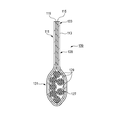
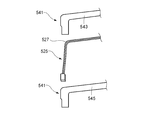
- FIG. 17 is a plan view showing the main part of the wire harness sheet which is folded and fixed to the bent part of the electric wire group together with the wire harness.
- a wire harness sheet 531 shown in FIG. 17 is composed of a single sheet base material 529, and is provided with an adhesive layer on one surface, folded back at a broken line portion 523, and adhesively fixed to a bent portion 527 of an electric wire group 525.
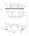
- the wire harness sheet 541 shown in FIG. 18 is composed of two sheet base materials 543 and 545, an adhesive layer is provided on one surface, and both the adhesive layers facing each other are overlapped to bend the electric wire group 525. It is adhesively fixed to the part 527.
- These conventional wire harness sheet 531 and wire harness sheet 541 are formed by cutting into a shape that matches the bent shape of the wire group 525.
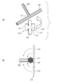
- Patent Document 1 a wire harness in which a protective sheet 513 having an adhesive layer on the back surface is wound around and fixed to a T-shaped branch portion 511 where a branch line 509 branches from a main line 507.
- a protective structure for the bifurcation is disclosed.
- the protective sheet 513 has a cross shape in which a vertical and horizontal continuous portion 519 of a vertical portion 515 and a horizontal portion 517 is cut from both ends.
- the vertical and horizontal continuous portion 519 is wound around the outer peripheral surface of the trunk line 507 opposite to the branch side, and the lateral portions 517 on both sides are spread over the entire outer peripheral surface of the main line 507 on both sides of the branch portion.
- both sides of the vertical part 515 are fixed to the outer peripheral surfaces of the opposite half circumferences from the trunk line 507 to the branch line 509 of the branch part 511, and both sides of the vertical part 515 are bonded and fixed on both sides of the branch line 509 to branch.
- the entire outer peripheral surface of the trunk line 507 and the branch line 509 at the position is covered with a protective sheet 513.
- the wire harness sheet 501 shown in FIGS. 16A and 16B has an adhesive on the bonding surface, and once the wire group 503 sticks to the adhesive surface, it is difficult to peel off. Therefore, the electric wire group 503 may be bent as shown in FIG.
- the wire harness sheet 501 is bonded in this state, as shown in FIG. 16B, the wire harness 505 has a problem that the appearance of the wire harness 505 is lowered or the wire group 503 is shorter than a predetermined length. For this reason, in the manufacturing method of the wire harness using the sheet
- the wire harness sheet 531 and the wire harness sheet 541 shown in FIGS. 17 and 18 are cut in accordance with the bent shape of the electric wire group 525, the yield is poor and the cost is increased. It was. Moreover, since it was a sticking operation
- the protective sheet 513 shown in FIGS. 19A and 19B is formed in a cross shape, when this is used for the linear electric wire group 503, the covering center portion swells to a large diameter. There's a problem.
- the manufacture of the protective sheet 513 requires die cutting, which increases costs and has a complicated shape, which makes it difficult to store and transport, and is difficult to handle.
- the present invention has been made in view of the above situation, and a first object thereof is a wire harness sheet that does not require a special processing machine and can be fixed at an accurate position without bending a wire group manually. It is providing the manufacturing method of a wire harness and a wire harness.
- a second object of the present invention is to provide a wire harness sheet, a wire harness, and a method of manufacturing a wire harness that can improve the yield and reduce the cost and can easily perform the work.
- the first object of the present invention is achieved by the following configurations (1) to (5).
- a sheet base material formed into a quadrangle by a pair of parallel first and second sides, and a third and fourth sides orthogonal thereto, the first side, and the first side
- An adhesive layer provided on one surface of the sheet base material on which the electric wire group is placed in parallel with two sides, and the first side provided in proximity to the third side and the fourth side
- a wire harness sheet comprising: slits formed by cutting between at least one of a portion and the second side portion along the third side portion and the fourth side portion to a placement region of the electric wire group. .
- the linear group of electric wires is placed in the placement area of the sheet base material, and the sheet base material has an end of the placement area that is more than the slit. It is fixed to the electric wire group by a pair of temporary fixing sheet pieces formed on the outside. Both sides of the planar sheet base material are fixed to both sides of the linear electric wire group, and the sheet base material is fixed in a state along the linear electric wire group. In this state, when the fixed sheet portion sandwiched between the pair of temporarily fixed sheet pieces is attached to the electric wire group, the sheet base material is positioned in the electric wire group by the temporarily fixed sheet piece portion. The part is fixed to the electric wire group at an accurate position.
- seat base material fixed to an electric wire group becomes the same width or the same diameter by the temporarily fixed sheet piece part and this fixed sheet part. Furthermore, since the sheet base material is rectangular, it can be manufactured at low cost, and handling such as storage and conveyance is easy.
- the sheet base material is bonded to the electric wire group placed in the center of the sheet base material by folding in two with the position of the electric wire group being the bending position.
- the wire group can be sandwiched and covered with an easy and short-time operation.
- the temporary fixing sheet piece and the main fixing sheet are wound around the wire group placed along the first side portion of the sheet base.
- the wire group can be covered with the same outer diameter.
- the fixed sheet portion sandwiched between the fixed sheet pieces is attached to the wire group by the adhesive layer. Wire harness is fixed.
- both sides of the linearly stretched electric wire group are fixed by the pair of temporary fixing sheet pieces of the sheet base material, and the sheet base material without wrinkles in the electric wire group without slack Are relatively positioned. Since this fixed sheet portion is wound around the central portion of the electric wire group in this positioned state, the sheet base material is positioned and fixed at an accurate position on the linear electric wire group, and a uniform wire harness having a good appearance can be obtained at low cost. It is done.
- a wire harness sheet comprising: slits formed by cutting between at least one of a portion and the second side portion along the third side portion and the fourth side portion to a placement region of the electric wire group.
- a pair of temporarily fixed sheet pieces provided on both sides of the sheet base material are fixed to both sides of the linearly stretched electric wire group.
- seat base material will be positioned with respect to the electric wire group which has not produced the bending.
- the main fixing sheet portion positioned between the pair of temporary fixing sheet pieces is fixed to the electric wire group between the temporary fixing sheet pieces. It will be fixed to the group.
- the temporarily fixed sheet piece portion acts as a fixing means for preventing positional displacement.
- the second object of the present invention is achieved by the following configurations (6) to (10).
- (6) A pair of parallel first and second sides and a third and fourth sides perpendicular to these are formed into a quadrangle, and an adhesive layer is provided on one surface and folded or A sheet base material that is adhered and fixed by being sandwiched by a sandwiching part that is bonded by overlapping and parallel to the first side part and is spaced apart from the first side part, and the sandwiching from the pasting end on the first side part side
- the holding part spaced from the first side part sandwiches the electric wire group parallel to the first side part. Fix with adhesive.
- a slit formed by cutting is disposed in the bonding portion between the bonding edge on the first side portion side and the clamping portion.
- the electric wire group adhesively fixed to the holding portion can be bent to the side opposite to the slit when the slit formed in the bonding portion is opened at the bonding end. Further, since the sheet base material is rectangular, the yield is improved, the sheet base can be manufactured at a low cost, and handling such as storage and transportation is easy.
- the sheet base material is folded and folded in half with respect to the electric wire group placed at the center of one sheet base material, with the position of the electric wire group being the folding position.
- the bonding margin is reduced, and the entire area of the sheet base material can be reduced.
- the electric wire group is placed on the second side separated from the first side of one of the two sheet bases, and the other sheet base is placed. By overlapping and sticking, it is possible to cover the electric wire group with easy and short work. Further, since the sheet base material is composed of two sheets, the size per sheet is smaller than that of a single sheet base material, and storage and handling can be facilitated.
- a pair of parallel first and second sides and a third side and a fourth side perpendicular to these are formed into a quadrangle, and an adhesive layer is provided on one surface and folded or A sheet base material that is adhered and fixed by being sandwiched by a sandwiching part that is bonded by overlapping and parallel to the first side part and is spaced apart from the first side part, and the sandwiching from the pasting end on the first side part side
- the linearly stretched electric wire group is fixed to the holding portion.
- the wire group adhesively fixed to the clamping part can be bent to the opposite side of the slit by opening the slit provided in the bonding part at the bonding end, and can be routed to a predetermined bending path Become.
- the slit opened at the bonding portion is prevented from further tearing by the tear stopper formed at the end of the slit.
- the yield is good and the material cost can be reduced.
- a pair of parallel first and second sides and a third and fourth sides perpendicular to these are formed into a quadrangle, and an adhesive layer is provided on one surface and folded or A sheet base material that is adhered and fixed by being sandwiched by a sandwiching part that is bonded by overlapping and parallel to the first side part and is spaced apart from the first side part, and the sandwiching from the pasting end on the first side part side
- a sheet for a wire harness comprising a slit formed by cutting in a bonded part between the part and a circular tear stopper formed at a terminal end of the slit on the clamping part side
- the sheet base material is used with the position of the electric wire group being a bending position with respect to the electric wire group placed linearly at the center of one sheet base material.
- the electric wire group can be easily sandwiched and covered by the sandwiching portion by folding back and pasting the two together. Or, by placing the wire group in a straight line on the second side that is separated from the first side of one of the two sheet base materials, the other sheet base material is overlaid and pasted, so that the wire group Can be easily sandwiched and covered. Since the sheet base material is a quadrangle, the bonding operation is simplified. As in the prior art, it is not necessary to bend and fix the wire group while being bent along the sheet base formed in a bent shape, so that the work is easy without requiring skill.
- FIG. 1 is a plan view of a wire harness sheet according to the first embodiment of the present invention.
- FIG. 2 is a process diagram showing a method of manufacturing a wire harness using the wire harness sheet shown in FIG. 1 in the order of (a) to (d).
- 3 is a sectional view taken along line III-III in FIG.
- FIG. 4 is a plan view of a branch-attached wire harness according to a modification in which the wire harness-attached group having a T-shaped branch portion is covered using the wire harness sheet shown in FIG. 1.
- FIG. 5 is a plan view of a wire harness sheet according to the second embodiment of the present invention.
- FIG. 6 is a process diagram showing a method of manufacturing a wire harness using the wire harness sheet shown in FIG.
- FIG. 7 is a sectional view taken along line VII-VII in FIG.
- FIG. 8 is a plan view of a wire harness sheet according to a third embodiment of the present invention.
- FIG. 9 is a process diagram showing a method of manufacturing a wire harness using the wire harness sheet shown in FIG. 8 in the order of (a) to (b).
- FIG. 10 is a sectional view taken along line XX in FIG.
- FIG. 11 is a plan view showing an example of use of the wire harness shown in FIG.
- FIG. 12 is a plan view of a wire harness sheet according to a fourth embodiment of the present invention.
- FIG. 13 is a process diagram showing a method of manufacturing a wire harness using the wire harness sheet shown in FIG.
- FIG. 14 is a cross-sectional view taken along the line XIV-XIV in FIG.
- FIG. 15: is a top view of the wire harness with a branch line which concerns on the modification which uses the sheet
- 16A is a plan view of a conventional wire harness sheet on which an electric wire group is placed
- FIG. 16B is a perspective view of the wire harness on which the wire harness sheet of FIG. 16A is bonded.
- FIG. 17 is a plan view showing a main part of a conventional wire harness sheet which is folded and fixed to a bent part of an electric wire group together with the wire harness.
- FIG. 18 is a plan view showing a main part of a conventional wire harness sheet that is adhered and fixed on a bent portion of an electric wire group together with the wire harness.
- FIG. 19A is a perspective view of a wire group having a T-shaped branch portion and a cross-shaped wire harness sheet
- FIG. 19B is a cross-sectional view showing a method of fixing the wire harness sheet of FIG. FIG.
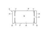
- FIG. 1 is a plan view of a wire harness sheet according to the first embodiment of the present invention.
- the wire harness sheet 11 according to the first embodiment is roughly divided into a sheet base material 13, an adhesive layer 15 (see FIG. 3), and a slit 17.
- the sheet base 13 is formed into a quadrangle by a pair of parallel first side 19 and second side 21 and a third side 23 and fourth side 25 that are orthogonal to these.
- known polyolefin resins such as polyethylene and polypropylene, polyurethane resins, polystyrene resins, acrylic resins, vinyl chloride resins, polycarbonate resins, and other plastics can be used.
- the adhesive layer 15 is provided on one surface of the sheet base material 13 on which the electric wire group 27 (see FIG. 2) is placed in parallel with the first side 19 and the second side 21. In the electric wire group 27, a plurality of covered electric wires 29 (see FIG. 3) are bundled to form a straight line.
- the adhesive layer 15 is formed by being provided on the entire surface on which the electric wire group 27 is installed or a part thereof.
- various known adhesives such as acrylic, rubber and silicone can be used.
- the slit 17 is provided close to the third side portion 23 and the fourth side portion 25, and extends along at least one of the first side portion 19 and the second side portion 21 along the third side portion 23 and the fourth side portion 25. In parallel, a cut is formed between the electric wire group 27 and the mounting area 31.
- the placement region 31 is provided at an equal distance from the first side portion 19 and the second side portion 21.
- the pair of slits 17 are formed by cutting from both the first side 19 and the second side 21 toward the placement region 31. Accordingly, the slit 17 is not formed in the placement region 31.
- the slit 17 is illustrated with a gap for the sake of clarity.
- the slit 17 is actually only cut and formed in the sheet base material 13, no gap is generated. Of course, it is also possible to form a slit having a gap as shown. Therefore, in the wire harness sheet 11 of the first embodiment, the left and right outer sides of the slits 17 are temporarily fixed sheet piece portions 33, and the left and right inner sides of the slits 17 sandwiched between the pair of temporarily fixed sheet piece portions 33 are permanently fixed. It becomes the sheet part 35. That is, the wire harness sheet 11 is provided with the slits 17 so that the temporarily fixed sheet piece portions 33 having degrees of freedom on both the left and right sides are formed. In the wire harness sheet 11, the slits 17 may be provided on either the left or right side instead of the left and right sides.
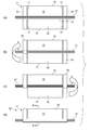
- FIG. 2 is a process diagram showing a method of manufacturing a wire harness using the wire harness sheet shown in FIG. 1 in the order of (a) to (d), and FIG. 3 is a cross-sectional view taken along line III-III in FIG. FIG.
- the electric wire group 27 is set to the adhesion layer 15 of the sheet
- the electric wire group 27 is set at the center of the sheet base material 13 (that is, the placement region 31). Further, in this setting, the electric wire group 27 is tensioned so as not to loosen.
- either the left or right (left in the first embodiment) temporary fixing sheet piece 33 is placed on the opposite temporary fixing sheet piece with the electric wire group 27 interposed therebetween.
- the sheet is folded in half so as to overlap with 33, and the temporary fixing sheet piece 33 on one side is adhesively fixed to the wire group 27.
- the temporary fixing sheet piece 33 on either the left or right side (right side in the first embodiment) is placed on the opposite side of the temporary fixing sheet piece portion with the electric wire group 27 in between.
- the other half temporary fixing sheet piece 33 is adhesively fixed to the electric wire group 27.
- the remaining temporarily fixed sheet piece 33 is fixed to the electric wire group 27 so that the electric wire group 27 does not loosen.
- the remaining main fixing sheet portion 35 is folded in half with the electric wire group 27 interposed therebetween, and is overlapped with the main fixing sheet portion 35 on the opposite side with the electric wire group 27 interposed therebetween.
- this fixed sheet part 35 and the electric wire group 27 are adhesively fixed.
- the wire harness sheet 11 is used, the step of placing the electric wire group 27 on one surface of the sheet base material 13, and the slit of the sheet base material 13 A step of fixing the pair of temporarily fixed sheet pieces 33 formed on the outside of the wire group 27 to the electric wire group 27 by the adhesive layer 15, and fixing the temporarily fixed sheet pieces 33 to the pair of temporarily fixed sheet pieces 33. A step of fixing the pinned fixed sheet portion 35 to the electric wire group 27 with the adhesive layer 15.
- the sheet By fixing a pair of temporary fixing sheet pieces 33 provided on both sides of the sheet base material 13 to both sides of the linearly-carrying electric wire group 27, the sheet can be attached to the electric wire group 27 that is not bent.
- the base material 13 is positioned.
- the main fixing sheet portion 35 positioned between the pair of temporary fixing sheet piece portions 33 is fixed to the electric wire group 27 between the temporary fixing sheet piece portions 33, so that the main fixing sheet portion 35 is It will be fixed to the electric wire group 27 at an accurate position. That is, the temporarily fixed sheet piece portion 33 functions as a fixing means for preventing the positional deviation.
- the wire group 27 stretched linearly is placed on the placement region 31 of the sheet base material 13, and the sheet base material 13 is placed on the placement region 31.
- the ends are fixed to the electric wire group 27 by a pair of temporary fixing sheet pieces 33 formed outside the slit 17.
- Both sides of the planar sheet base material 13 are fixed to both sides of the linear electric wire group 27, and the sheet base material 13 is fixed in a state along the linear electric wire group 27.
- the fixed sheet portion 35 sandwiched between the pair of temporarily fixed sheet piece portions 33 is attached to the electric wire group 27 in this state, the sheet base material 13 is positioned on the electric wire group 27 by the temporarily fixed sheet piece portion 33.
- the fixed sheet portion 35 is fixed to the electric wire group 27 at an accurate position.
- the sheet base material 13 fixed to the electric wire group 27 has the same width W or the same diameter D in the temporarily fixed sheet piece portion 33 and the main fixed sheet portion 35. Furthermore, since the sheet base material 13 has a rectangular shape, it can be manufactured at low cost, and handling such as storage and conveyance is easy.
- the sheet base material 13 is folded in half with respect to the electric wire group 27 placed at the center of the sheet base material 13 with the position of the electric wire group 27 being the folding position.
- the electric wire group 27 can be sandwiched and covered with an easy and short work.
- FIG. 4 is a plan view of a branch-attached wire harness 43 according to a modification in which the wire harness-attached group 41 having the T-shaped branch portion 39 is covered using the wire harness sheet 11 shown in FIG.
- the sheet 11 for wire harness according to the first embodiment can be suitably used also when protecting the branch-attached electric wire group 41 having, for example, a T-shaped branch portion 39 that branches the branch line 47 from the main line 45. . That is, the wire harness sheet 11 can be used for both the linear electric wire group 27 and the branch-attached electric wire group 41.
- the trunk line 45 is placed on the placement region 31, and the branch line 47 is placed on one of the main fixed sheet portions 35.
- the main wire 45 is folded in half so that the left and right temporary fixing sheet pieces 33 overlap the temporary fixing sheet piece 33 on the opposite side across the main wire 45.
- the piece 33 is adhesively fixed to the main line 45.
- main fixing sheet portion 35 is folded in half with the branch portion 39 interposed therebetween, and is overlapped with the main fixing sheet portion 35 on the opposite side with the main line 45 in between, so that the main fixing sheet portion 35 and the electric wire with branch line
- the group 41 is adhesively fixed.
- FIG. 5 is a plan view of a wire harness sheet 49 according to the second embodiment of the present invention.
- the same members / parts as those of the wire harness sheet 11 according to the first embodiment shown in FIGS. 1 to 3 are denoted by the same reference numerals, and redundant description is omitted.
- the placement region 51 is provided in the sheet base material 13 close to the first side portion 19, and the pair of slits 53 are cut and formed only from the second side portion 21. The The slit 53 is not formed in the placement area 51.
- the left and right outer sides of the slits 53 are temporarily fixed sheet piece portions 55, and the left and right inner sides of the slits 53 sandwiched between the pair of temporarily fixed sheet piece portions 55 are the permanently fixed sheet portions. 57. That is, the wire harness sheet 49 is provided with the slits 53, whereby the temporarily fixed sheet piece portions 55 having degrees of freedom on both the left and right sides are formed. In the wire harness sheet 49, the slits 53 may be provided on either the left or right instead of the left and right sides.
- FIG. 6 is a process diagram showing a method of manufacturing the wire harness 59 using the wire harness sheet 49 shown in FIG. 5 in the order of (a) to (d), and FIG. It is VII sectional drawing.
- the electric wire group 27 is set to the adhesion layer 15 (refer FIG. 7) of the sheet
- the electric wire group 27 is set on the sheet base material 13 (that is, the placement area 51) in the vicinity of the first side portion 19. Further, in this setting, the electric wire group 27 is tensioned so as not to loosen.
- either one of the left and right (left in the second embodiment) temporary fixing sheet piece 55 is wound around the electric wire group 27 in a multiple manner, and the temporary fixing sheet piece on one side is wound.
- the part 55 is adhesively fixed to the electric wire group 27.
- the temporary fixing sheet piece 55 on either the left or right side (right side in the second embodiment) is wound around the electric wire group 27 in a multiple manner, and the remaining one side is temporarily fixed.
- the sheet piece 55 is adhesively fixed to the electric wire group 27.
- the remaining temporarily fixed sheet piece 55 is fixed to the electric wire group 27 so that the electric wire group 27 does not loosen.
- the remaining main fixing sheet portion 57 is wound around the electric wire group 27 multiple times, and the main fixing sheet portion 57 and the electric wire group 27 are adhesively fixed. Thereby, the manufacture of the wire harness 59 in which the electric wire group 27 is covered with the wire harness sheet 49 is completed.
- the temporarily fixed sheet piece portion 55 and the main fixed sheet portion 57 are multiplexed around the electric wire group 27 placed along the first side portion 19 of the sheet base material 13.
- the wire group 27 can be covered with the same outer diameter D by being wound around.
- the pair of temporarily fixed sheet pieces 33 (55) formed outside the slits 17 (53) of the sheet base material 13 has an adhesive layer on the electric wire group 27. 15 is fixed. Thereafter, the permanent fixing sheet portion 35 (57) sandwiched between the pair of temporarily fixing sheet piece portions 33 (55) is fixed to the electric wire group 27 by the adhesive layer 15. For this reason, both sides of the linearly stretched electric wire group 27 are fixed by the pair of temporarily fixed sheet piece portions 33 (55) of the sheet base material 13, and the sheet base material 13 without wrinkles is relative to the wire group 27 without slack Positioned.
- this fixed sheet portion 35 (57) is wound around the central portion of the electric wire group 27 in this positioned state, the sheet base material 13 is positioned and fixed at an accurate position on the linear electric wire group 27, and it looks good and is uniform.
- a simple wire harness 37 (59) can be obtained at low cost.
- the electric wire group 27 can be fixed at an accurate position without being bent manually.
- FIG. 8 is a plan view of a wire harness sheet according to a third embodiment of the present invention.
- the wire harness sheet 111 according to the third embodiment is roughly divided into a sheet base material 113, an adhesive layer 115 (see FIG. 10), and a slit 117.
- the sheet base 113 is formed into a quadrangle by a pair of parallel first side 119 and second side 121 and a third side 123 and fourth side 125 orthogonal to these.
- plastics such as polyolefin resin such as polyethylene and polypropylene, polyurethane resin, polystyrene resin, acrylic resin, vinyl chloride resin, polycarbonate resin and the like can be used as in the case of the sheet base 13.
- the adhesive layer 115 is provided on one surface of the sheet base 113 on which the wire group 127 (see FIG. 9A) is placed in parallel with the first side 119 and the second side 121.
- the electric wire group 127 a plurality of covered electric wires 129 (see FIG. 10) are bundled to form a linear shape.
- the adhesive layer 115 is formed by providing the entire surface on which the electric wire group 127 is installed or a part thereof.
- various known adhesives such as acrylic, rubber and silicone can be used.
- the sheet base material 113 is attached by folding, and a clamping part 131 that separates the electric wire group 127 parallel to the first side part 119 from the first side part 119 (see FIG. 9B). Fix with adhesive.
- a slit 117 is formed in a direction orthogonal to the electric wire group 127 at a bonding portion 135 (see FIG. 9B) between the bonding end 133 on the first side 119 side and the sandwiching portion 131. Is formed by cutting.
- the sandwiching portion 131 is provided in the central portion of the sheet base material 113, in the developed sheet base material 113, as shown in FIG. 8, the first side portion 119 and the second side portion are provided.
- the slit 117 is cut and formed from both sides.
- the slit 117 is illustrated with a gap for the sake of clarity. However, since the slit 117 is actually cut and formed in the sheet base material 113, no gap is generated. Of course, it is also possible to form a slit having a gap as shown.
- the number of slits 117 formed by cutting from the first side portion 119 and the second side portion 121 can be arbitrary. If the number of the slits 117 is increased, the wire harness 139 can correspond to an arc having a smaller bending radius and a curve closer to a curve. In the third embodiment, a total of four slits 117 are formed in pairs from both the first side 119 and the second side 121.
- a circular tear stopper 137 is formed at the end of the slit 117 on the clamping part 131 side. The tear stopper 137 is an open C-shaped hole, and both ends thereof are connected to both edges forming the slit 117.
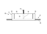
- FIG. 9 is a process diagram showing the manufacturing method of the wire harness 139 using the wire harness sheet 111 shown in FIG. 8 in the steps (a) to (b), and FIG. 10 is an X- It is X sectional drawing.
- the linear electric wire group 127 is set to the adhesion layer 115 of the sheet
- the electric wire group 127 is placed on the central portion (that is, the sandwiching portion 131) of the wire harness sheet 111. Further, the electric wire group 127 is stretched so as not to loosen.
- the wire harness sheet 111 is folded back into two.
- the wire harness sheet 111 is adhesively fixed so that the opposing slit 117 and tear-preventing portion 137 overlap each other. That is, the electric wire group 127 is adhesively fixed to the sandwiching portion 131 while the slits 117 and the tear preventing portions 137 are matched.
- the position of the wire group 127 is set to the folding position with respect to the wire group 127 placed linearly at the center of one sheet base material 113.
- the electric wire group 127 can be easily sandwiched and covered by the sandwiching portion 131 by folding the base material 113 and pasting the base material 113 together. Further, since the sheet base 113 is a quadrangle, the bonding operation is simplified. As in the prior art, it is not necessary to bend and fix the wire group 127 while being bent along the sheet substrate formed in a bent shape, so that the work is easy without requiring skill.
- the sandwiching part 131 spaced from the first side part 119 is parallel to the first side part 119.
- the wire group 127 is sandwiched and fixed.
- a slit 117 formed by cutting is disposed in the bonding portion 135 between the bonding end 133 on the first side portion 119 side and the sandwiching portion 131.
- the electric wire group 127 adhered and fixed to the holding portion 131 can be bent to the opposite side of the slit 117 by opening the slit 117 formed in the bonding portion 135 at the bonding end 133.
- the sheet base material 113 has a quadrangular shape, the yield is improved, the sheet base 113 can be manufactured at low cost, and handling such as storage and conveyance is easy. Furthermore, since one sheet base material 113 can be folded back with the electric wire group 127 as an end, the bonding margin is smaller than when two sheets are bonded together, and the entire area of the sheet base material can be reduced (see FIG. 14). ).
- FIG. 11 is a plan view showing an example of use of the wire harness 139 shown in FIG.
- a single sheet base material 113 is attached by folding, and the electric wire group 127 is adhesively fixed to the sandwiching portion 131.
- a wire group 127 stretched in a straight line is fixed to the sandwiching portion 131.
- the electric wire group 127 adhered and fixed to the holding portion 131 can be bent to the side opposite to the slit 117 by opening the slit 117 provided in the bonding portion 135 at the bonding end 133. Thereby, the wiring to a predetermined bending path
- the slit 117 opened at the bonding portion 135 is prevented from further tearing by the tear stopper portion 137 formed at the end of the slit 117. Further, since the wire harness 139 does not have to be formed by cutting the sheet base material 113 in a planar shape after bending, the yield is good and the material cost can be reduced.
- FIG. 12 is a plan view of a wire harness sheet 141 according to the fourth embodiment of the present invention.
- the sheet base material 143 is composed of two sheets and is adhered and fixed in an overlapping manner.
- Each sheet base material 143 is formed in a quadrangular shape by a pair of parallel first side 119 and second side 121 and third side 123 and fourth side 125 orthogonal thereto. That is, the two sheet base materials 143 are formed in the same shape, and the pressure-sensitive adhesive layer 115 (see FIG. 14) is provided on one surface serving as a bonding surface of both.
- the sandwiching portion 131 that is separated from the first side portion 119 is provided in the vicinity of the second side portion 121 of the sheet base material 143.
- a linear electric wire group 127 (see FIG. 13) is disposed on the clamping portion 131 and is fixed by adhesion.
- the slit 117 is cut and formed in the bonding portion 135 between the first side portion 119 and the sandwiching portion 131 in each sheet base material 143.
- a pair of slits 117 is formed in each sheet base material 143.
- a circular tear stopper 137 is formed at the end of the slit 117 on the clamping part 131 side.
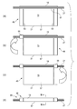
- FIG. 13 is a process diagram showing a manufacturing method of the wire harness 145 using the wire harness sheet 141 shown in FIG. 12 in the order of (a) to (b), and FIG. 14 is an XIV- in FIG. 13 (b). It is XIV sectional drawing.
- the linear electric wire group 127 is set in the sandwiching portion 131 of the one sheet base material 143 with the adhesive layer 115 facing upward. At this time, the electric wire group 127 is tensioned so as not to loosen.
- the pressure-sensitive adhesive layer 115 side of the other sheet base material 143 is bonded by overlapping.
- both the sheet base materials 143 are adhesively fixed so that the opposing slits 117 and tear stoppers 137 overlap each other.
- the wire group 127 is adhesively fixed to the holding portion 131 while the slits and the tear-off portions are matched.
- the electric wire group 127 is linearly mounted on the second side 121 side that is separated from the first side 119 of one sheet base material 143 out of the two sheets.
- the sheet base material 143 is a square, bonding work becomes easy.
- the wire harness sheet 141 according to the fourth embodiment includes two sheet base materials 143. Therefore, the sheet base sheet 143 is smaller in size than the single sheet base material 113, and can be stored and handled. It becomes easy.
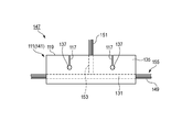
- FIG. 15 is a plan view of a wire harness 147 with a branch line according to a modification using the wire harness sheet 111 or the wire harness sheet 141 according to the third or fourth embodiment of the present invention.
- the wire harness sheet 111 (141) can also be suitably used for protecting a branch-attached electric wire group 155 having, for example, a T-shaped branch portion 153 obtained by branching the branch line 151 from the main line 149. That is, the wire harness sheet 111 (141) can be used for both the linear wire group 127 and the branch-attached wire group 155.
- the branch-attached electric wire group 155 is adhesively fixed to the holding part 131 in the same manner as the case where the main line 149 is the electric wire group 127 described above.
- the branch line 151 is adhesively fixed to the bonding part 135 and led out from the first side part 119 side. Thereby, the wire harness 147 with a branch line covered with the sheet
- the yield is improved and the cost is reduced. It can be reduced and the operation can be easily performed.
- seat 11,111,141 for wire harnesses of the said 1st, 3rd, 4th embodiment can use the self-adhesive sheet which can be bonded together only by aligning own adhesive layers.
- the self-adhesive sheet can be easily applied only by aligning the adhesive surfaces without using glue or a binding tape.
- the self-adhesive sheet does not cause the special pressure-sensitive adhesive layer to stick to the electric wire bundle, the operator's fingers, or the like, and does not deteriorate the assembly workability.
- a surface material is laminated on the surface of a sheet base material made of PP (polypropylene) foam, and a special pressure-sensitive adhesive layer (adhesive layer) is laminated on the back surface.
- PP polypropylene
- a special pressure-sensitive adhesive layer adheresive layer
- Kraft paper, liner board, PET (polyethylene terephthalate) film, PP film, non-woven fabric, etc. can be used as the surface material.
- Tensile strength is 49 N / cm width in the vertical direction, 23 N / cm width in the horizontal direction (according to JIS K-6767), and tear strength is 7.8 N in the vertical direction and 6.8 N in the horizontal direction (JIS K- 6767), water vapor permeability is 0.0052 g / cm 2 ⁇ 24 hrs (FS-101B), initial adhesive strength is 2.5 N / cm width (T-type peel test), and the like.
- this single-sided self-adhesive sheet for example, Cro-nel (registered trademark) manufactured by Crowell, Inc. of the United States can be used.
- the pressure-sensitive adhesive layer of the present invention is not limited to the above-mentioned special pressure-sensitive adhesive layer, and it goes without saying that various known pressure-sensitive adhesive layers can be used.
- a sheet base 13 formed into a quadrangle by a pair of parallel first side 19 and second side 21 and a third side 23 and fourth side 25 perpendicular to the first side 19 and the second side 21, and the first
- the adhesive layer 15 provided on one surface of the sheet base material 13 on which the wire group 27 is placed in parallel with the side 19 and the second side 21, the third side 23, and the fourth side
- a placement region 31 of the electric wire group 27 is provided near the portion 25 along the third side portion 23 and the fourth side portion 25 from at least one of the first side portion 19 and the second side portion 21. , 51, 51, 51, 51.
- a pair of temporarily fixed sheet pieces 33 and 55 formed on the outside A wire harness that is fixed to the electric wire group 27 by the adhesive layer 15 and the fixed sheet portions 35 and 57 sandwiched between the pair of temporary fixing sheet pieces 33 and 55 are fixed to the electric wire group 27 by the adhesive layer 15. 37,59.
- the adhesive layer 15 provided on one surface of the sheet base material 13 on which the wire group 27 is placed in parallel with the side 19 and the second side 21, the third side 23, and the fourth side
- a placement region 31 of the electric wire group 27 is provided near the portion 25 along the third side portion 23 and the fourth side portion 25 from at least one of the first side portion 19 and the second side portion 21.
- a pair of parallel first side portion 119 and second side portion 121 and a third side portion 123 and a fourth side portion 125 orthogonal to the first side portion 119 and the second side portion 121 are formed into a quadrangle, and the adhesive layer 115 is formed on one surface.
- Wire harness sheets 111 and 141 each having a tear-stop portion 137.
- a pair of parallel first side 119 and second side 121 and a third side 123 and fourth side 125 perpendicular to the first side 119 and the second side 121 are formed into a quadrangle and have an adhesive layer 115 on one surface.
- Sheet base materials 113 and 143 that are adhesively fixed by sandwiching a wire group 127 parallel to the first side 119 and sandwiched by a sandwiching part 131 spaced from the first side 119, and provided by folding or overlapping.
- the wire group 127 provided on one surface of the sheet base material 113, 143, and the sheet base material 113, 143 is folded.
- Wire harnesses 139 and 145 that are bonded together by reversing or overlapping, and the wire group 127 is adhesively fixed to the holding portion 131.
- a pair of parallel first side portion 119 and second side portion 121 and a third side portion 123 and a fourth side portion 125 orthogonal to these are formed into a quadrangle, and the adhesive layer 115 is formed on one surface.
- this invention is not limited to embodiment mentioned above, A deformation
- the material, shape, dimensions, number, arrangement location, and the like of each component in the above-described embodiment are arbitrary and are not limited as long as the present invention can be achieved.
- Japanese patent applications Japanese Patent Application Nos. 2012-032013 and 2012-032014 filed on Feb. 16, 2012, the contents of which are incorporated herein by reference.
- the wire harness sheet, the wire harness, and the wire harness manufacturing method according to the present invention a special processing machine is not required, and the wire group can be fixed at an accurate position without being bent manually.
- the yield can be improved and the cost can be reduced, and the operation can be easily performed.
Abstract
Provided is a sheet for a wire harness that makes it possible to fix a group of wires in an exact position without bending the wires by hand. The sheet (11) for a wire harness is provided with: a sheet substrate (13) that has a quadrilateral shape formed by a first side section (19), a second side section (21), a third side section (23), and a fourth side section (25); an adhesive layer (15) that is provided on one surface of the sheet substrate (13); and slits (17) that are each formed by cutting parallel to the third side section (23) and the fourth side section (25) in the area between a mounting region (31) for a group of electric wires (27) and the first side section (19) and the second side section (21).
Description
本発明は、ワイヤハーネス用シート及びワイヤハーネス並びにワイヤハーネスの製造方法に関する。
The present invention relates to a wire harness sheet, a wire harness, and a method for manufacturing the wire harness.
自動車に配索される多数の電線群からなるワイヤハーネスは、これら電線群を集束すると共に保護するためにテープ巻きされている場合が多いが、近年、作業工数のかかるテープ巻きを廃止してシートを一括で貼り付け、電線群の集束保護をするものが提案されている。
In many cases, wire harnesses consisting of a large number of wire groups that are routed in automobiles are tape-wrapped to focus and protect these wire groups. Have been proposed to collectively protect the group of wires.
図16(a)及び図16(b)に示すように、この種のワイヤハーネス用シート501は、一方の面に粘着層が設けられていて、剥離紙をはがして指定位置に電線群503をセットし、粘着面を貼り合わすことで電線群を保護する。
図17は電線群の屈曲部に折り返して粘着固定されるワイヤハーネス用シートの要部をワイヤハーネスと共に示した平面図である。
図17に示すワイヤハーネス用シート531は、一枚のシート基材529からなり、一方の面に粘着層が設けられ、破線部523で折り返されて、電線群525の屈曲部527に粘着固定される。
図18は電線群の屈曲部に重ね合わせて粘着固定されるワイヤハーネス用シートの要部をワイヤハーネスと共に示した平面図である。
図18に示すワイヤハーネス用シート541は、二枚のシート基材543,545からなり、一方の面に粘着層が設けられ、粘着層を対面させる双方が重ね合わせられて、電線群525の屈曲部527に粘着固定される。これら、従来のワイヤハーネス用シート531及びワイヤハーネス用シート541は、電線群525の屈曲形状に合わせた形状に裁断して形成される。 As shown in FIGS. 16 (a) and 16 (b), this type ofwire harness sheet 501 is provided with an adhesive layer on one surface, and peels off the release paper to place the electric wire group 503 at a designated position. Set and protect the wire group by sticking the adhesive side together.
FIG. 17 is a plan view showing the main part of the wire harness sheet which is folded and fixed to the bent part of the electric wire group together with the wire harness.
Awire harness sheet 531 shown in FIG. 17 is composed of a single sheet base material 529, and is provided with an adhesive layer on one surface, folded back at a broken line portion 523, and adhesively fixed to a bent portion 527 of an electric wire group 525. The
FIG. 18 is a plan view showing a main part of the wire harness sheet, which is adhered and fixed to the bent part of the electric wire group, together with the wire harness.
Thewire harness sheet 541 shown in FIG. 18 is composed of two sheet base materials 543 and 545, an adhesive layer is provided on one surface, and both the adhesive layers facing each other are overlapped to bend the electric wire group 525. It is adhesively fixed to the part 527. These conventional wire harness sheet 531 and wire harness sheet 541 are formed by cutting into a shape that matches the bent shape of the wire group 525.
図17は電線群の屈曲部に折り返して粘着固定されるワイヤハーネス用シートの要部をワイヤハーネスと共に示した平面図である。
図17に示すワイヤハーネス用シート531は、一枚のシート基材529からなり、一方の面に粘着層が設けられ、破線部523で折り返されて、電線群525の屈曲部527に粘着固定される。
図18は電線群の屈曲部に重ね合わせて粘着固定されるワイヤハーネス用シートの要部をワイヤハーネスと共に示した平面図である。
図18に示すワイヤハーネス用シート541は、二枚のシート基材543,545からなり、一方の面に粘着層が設けられ、粘着層を対面させる双方が重ね合わせられて、電線群525の屈曲部527に粘着固定される。これら、従来のワイヤハーネス用シート531及びワイヤハーネス用シート541は、電線群525の屈曲形状に合わせた形状に裁断して形成される。 As shown in FIGS. 16 (a) and 16 (b), this type of
FIG. 17 is a plan view showing the main part of the wire harness sheet which is folded and fixed to the bent part of the electric wire group together with the wire harness.
A
FIG. 18 is a plan view showing a main part of the wire harness sheet, which is adhered and fixed to the bent part of the electric wire group, together with the wire harness.
The
また、特許文献1には、図19(a)に示すように、幹線507から支線509が分岐するT字状の分岐部分511に、裏面に粘着層を有する保護シート513を巻き付け固着するワイヤハーネス分岐部の保護構造が開示されている。
保護シート513は、十字形状として縦方向部分515と横方向部分517との縦横連続部519に両端から切り込み521を入れた形状とされる。そして、図19(b)に示すように、縦横連続部519を分岐側と反対側の幹線507の外周面に巻き付けて、両側の横方向部分517を分岐部両側の幹線507の外周面全面にそれぞれ一部が重なるように渦巻き状に巻き付けて固着する。一方、縦方向部分515の両側を分岐部分511の幹線507から支線509にかけて、対向する半周の外周面にそれぞれ固着し、支線509の両側で縦方向部分515の両側を貼り合わせ固着して、分岐位置の幹線507及び支線509の全外周面を保護シート513で被覆している。 InPatent Document 1, as shown in FIG. 19A, a wire harness in which a protective sheet 513 having an adhesive layer on the back surface is wound around and fixed to a T-shaped branch portion 511 where a branch line 509 branches from a main line 507. A protective structure for the bifurcation is disclosed.
Theprotective sheet 513 has a cross shape in which a vertical and horizontal continuous portion 519 of a vertical portion 515 and a horizontal portion 517 is cut from both ends. Then, as shown in FIG. 19B, the vertical and horizontal continuous portion 519 is wound around the outer peripheral surface of the trunk line 507 opposite to the branch side, and the lateral portions 517 on both sides are spread over the entire outer peripheral surface of the main line 507 on both sides of the branch portion. It is wound and fixed in a spiral shape so that each part overlaps. On the other hand, both sides of the vertical part 515 are fixed to the outer peripheral surfaces of the opposite half circumferences from the trunk line 507 to the branch line 509 of the branch part 511, and both sides of the vertical part 515 are bonded and fixed on both sides of the branch line 509 to branch. The entire outer peripheral surface of the trunk line 507 and the branch line 509 at the position is covered with a protective sheet 513.
保護シート513は、十字形状として縦方向部分515と横方向部分517との縦横連続部519に両端から切り込み521を入れた形状とされる。そして、図19(b)に示すように、縦横連続部519を分岐側と反対側の幹線507の外周面に巻き付けて、両側の横方向部分517を分岐部両側の幹線507の外周面全面にそれぞれ一部が重なるように渦巻き状に巻き付けて固着する。一方、縦方向部分515の両側を分岐部分511の幹線507から支線509にかけて、対向する半周の外周面にそれぞれ固着し、支線509の両側で縦方向部分515の両側を貼り合わせ固着して、分岐位置の幹線507及び支線509の全外周面を保護シート513で被覆している。 In
The
しかしながら、図16(a)及び図16(b)に示したワイヤハーネス用シート501は、貼り合わせ面に粘着剤がついており、一度粘着面に電線群503がくっついてしまうと剥がすことが困難なため、電線群503が図16(a)のように曲がったりして理想の位置につかないことがある。この状態でワイヤハーネス用シート501が貼り合わされると、図16(b)に示すように、ワイヤハーネス505は、見栄えが低下したり、電線群503が所定長よりも短くなる問題が生じた。このため、従来のワイヤハーネス用シート501を使用したワイヤハーネスの製造方法では、作業者が気遣いをしながら作業をしなければならず、時間がかかっていた。これに対して位置決め治具等の特別な製造設備を使用すればコストが増大した。
However, the wire harness sheet 501 shown in FIGS. 16A and 16B has an adhesive on the bonding surface, and once the wire group 503 sticks to the adhesive surface, it is difficult to peel off. Therefore, the electric wire group 503 may be bent as shown in FIG. When the wire harness sheet 501 is bonded in this state, as shown in FIG. 16B, the wire harness 505 has a problem that the appearance of the wire harness 505 is lowered or the wire group 503 is shorter than a predetermined length. For this reason, in the manufacturing method of the wire harness using the sheet | seat 501 for the conventional wire harness, the operator had to work while caring, and it took time. On the other hand, if special manufacturing equipment such as a positioning jig is used, the cost increases.
また、図17及び図18に示したワイヤハーネス用シート531やワイヤハーネス用シート541は、電線群525の屈曲形状に合わせて裁断加工していたため、歩留まりが悪く、コストを増大させる要因となっていた。また、電線群525の屈曲形状に、ワイヤハーネス用シート531やワイヤハーネス用シート541を合わせて粘着固定するのは、位置合わせを行いながらの貼着作業となるため、熟練を要した。そのうえ、粘着剤が電線群525に不用意にくっついてしまうと、剥がす時間がかかったり、シート基材529やシート基材543,545から接着剤が取れて電線群525に付いたりしてしまうことがあり、作業者は、気遣いをしながら作業をしなければならず、時間がかかっていた。
Moreover, since the wire harness sheet 531 and the wire harness sheet 541 shown in FIGS. 17 and 18 are cut in accordance with the bent shape of the electric wire group 525, the yield is poor and the cost is increased. It was. Moreover, since it was a sticking operation | work while performing position alignment, combining the sheet | seat 531 for wire harnesses and the sheet | seat 541 for wire harnesses with the bending shape of the electric wire group 525 required the skill. In addition, if the adhesive sticks inadvertently to the electric wire group 525, it may take time to peel off, or the adhesive may be removed from the sheet base material 529 and the sheet base materials 543 and 545 and attached to the electric wire group 525. Therefore, the worker had to work while taking care, and it took time.
また、図19(a)及び図19(b)に示した保護シート513は、十字形状として形成されるため、これを直線状の電線群503に使用した場合、被覆中央部が大径に膨らむ問題がある。また、保護シート513の製造には型抜きが必要となりコストが増大するとともに、形状が複雑なため、保管や搬送がしにくく、取り扱が難しいという問題があった。
Moreover, since the protective sheet 513 shown in FIGS. 19A and 19B is formed in a cross shape, when this is used for the linear electric wire group 503, the covering center portion swells to a large diameter. There's a problem. In addition, the manufacture of the protective sheet 513 requires die cutting, which increases costs and has a complicated shape, which makes it difficult to store and transport, and is difficult to handle.
本発明は上記状況に鑑みてなされたもので、その第1の目的は、特別な加工機を必要とせず、手作業で電線群を屈曲させずに正確な位置に固定できるワイヤハーネス用シート及びワイヤハーネス並びにワイヤハーネスの製造方法を提供することにある。
また、本発明の第2の目的は、歩留まりを改善してコストを低減できるとともに、容易に作業を行えるワイヤハーネス用シート及びワイヤハーネス並びにワイヤハーネスの製造方法を提供することにある。 The present invention has been made in view of the above situation, and a first object thereof is a wire harness sheet that does not require a special processing machine and can be fixed at an accurate position without bending a wire group manually. It is providing the manufacturing method of a wire harness and a wire harness.
A second object of the present invention is to provide a wire harness sheet, a wire harness, and a method of manufacturing a wire harness that can improve the yield and reduce the cost and can easily perform the work.
本発明に係る上記第1の目的は、下記構成(1)~(5)により達成される。
(1) 一対の平行な第1辺部及び第2辺部とこれらに直交する第3辺部及び第4辺部とによって四角形に形成されたシート基材と、前記第1辺部及び前記第2辺部と平行に電線群が載置される前記シート基材の一方の面に設けられた粘着層と、前記第3辺部と前記第4辺部に近接して設けられ前記第1辺部及び前記第2辺部の少なくとも一方から前記第3辺部と前記第4辺部に沿って前記電線群の載置領域までの間にそれぞれ切り込み形成されたスリットと、を備えるワイヤハーネス用シート。 The first object of the present invention is achieved by the following configurations (1) to (5).
(1) A sheet base material formed into a quadrangle by a pair of parallel first and second sides, and a third and fourth sides orthogonal thereto, the first side, and the first side An adhesive layer provided on one surface of the sheet base material on which the electric wire group is placed in parallel with two sides, and the first side provided in proximity to the third side and the fourth side A wire harness sheet, comprising: slits formed by cutting between at least one of a portion and the second side portion along the third side portion and the fourth side portion to a placement region of the electric wire group. .
上記(1)の構成のワイヤハーネス用シートによれば、シート基材の載置領域に、直線状に張った電線群が載置され、シート基材は、載置領域の端がスリットよりも外側に形成される一対の仮固定シート片部によって電線群に固定される。直線状となった電線群の両側に平面状のシート基材の両側が固定され、シート基材が直線状の電線群に沿った状態で固定される。この状態で一対の仮固定シート片部に挟まれる本固定シート部が電線群に貼り付けられると、シート基材は、仮固定シート片部にて電線群に位置決めされているので、本固定シート部が電線群に正確な位置で固定される。また、電線群に固定されるシート基材は、仮固定シート片部と本固定シート部とで、同一幅、若しくは同一径となる。更に、シート基材は矩形状であるので、安価に製造でき、保管や搬送といった取り扱いも容易となる。
According to the wire harness sheet configured as described in (1) above, the linear group of electric wires is placed in the placement area of the sheet base material, and the sheet base material has an end of the placement area that is more than the slit. It is fixed to the electric wire group by a pair of temporary fixing sheet pieces formed on the outside. Both sides of the planar sheet base material are fixed to both sides of the linear electric wire group, and the sheet base material is fixed in a state along the linear electric wire group. In this state, when the fixed sheet portion sandwiched between the pair of temporarily fixed sheet pieces is attached to the electric wire group, the sheet base material is positioned in the electric wire group by the temporarily fixed sheet piece portion. The part is fixed to the electric wire group at an accurate position. Moreover, the sheet | seat base material fixed to an electric wire group becomes the same width or the same diameter by the temporarily fixed sheet piece part and this fixed sheet part. Furthermore, since the sheet base material is rectangular, it can be manufactured at low cost, and handling such as storage and conveyance is easy.
(2) 上記(1)の構成のワイヤハーネス用シートであって、前記載置領域が前記第1辺部と前記第2辺部から等距離に設けられ、前記スリットが、前記第1辺部と前記第2辺部の双方から切り込まれるワイヤハーネス用シート。
(2) The wire harness sheet configured as described in (1) above, wherein the placement area is provided at an equal distance from the first side and the second side, and the slit is the first side. And a wire harness sheet cut from both of the second side portions.
上記(2)の構成のワイヤハーネス用シートによれば、シート基材の中央部に載置した電線群に対して、電線群の位置を折り曲げ位置とした二つ折りによりシート基材を貼り合わせることで、容易且つ短時間の作業で電線群を挟んで覆うことができる。
According to the wire harness sheet having the configuration of (2) above, the sheet base material is bonded to the electric wire group placed in the center of the sheet base material by folding in two with the position of the electric wire group being the bending position. Thus, the wire group can be sandwiched and covered with an easy and short-time operation.
(3) 上記(1)の構成のワイヤハーネス用シートであって、前記載置領域が前記第1辺部に近接して設けられ、前記スリットが、前記第2辺部のみから切り込み形成されるワイヤハーネス用シート。
(3) The wire harness sheet configured as described in (1) above, wherein the placement area is provided close to the first side portion, and the slit is formed by cutting only from the second side portion. Sheet for wiring harness.
上記(3)の構成のワイヤハーネス用シートによれば、シート基材の第1辺部に沿って載置される電線群を中心に、仮固定シート片部及び本固定シート部が多重に巻き付けられることで、電線群を同一外径で覆うことができる。
According to the wire harness sheet having the configuration of (3) above, the temporary fixing sheet piece and the main fixing sheet are wound around the wire group placed along the first side portion of the sheet base. As a result, the wire group can be covered with the same outer diameter.
(4) 一対の平行な第1辺部及び第2辺部とこれらに直交する第3辺部及び第4辺部とによって四角形に形成されたシート基材と、前記第1辺部及び前記第2辺部と平行に電線群が載置される前記シート基材の一方の面に設けられた粘着層と、前記第3辺部と前記第4辺部に近接して設けられ前記第1辺部及び前記第2辺部の少なくとも一方から前記第3辺部と前記第4辺部に沿って前記電線群の載置領域までの間にそれぞれ切り込み形成されたスリットと、前記シート基材の一方の面に設けられる前記電線群と、を備え、前記シート基材の前記スリットよりも外側に形成される一対の仮固定シート片部が前記電線群に前記粘着層によって固定され、前記一対の仮固定シート片部に挟まれる本固定シート部が前記電線群に前記粘着層によって固定されるワイヤハーネス。
(4) A sheet base material formed into a quadrangle by a pair of parallel first and second sides and a third and fourth sides orthogonal to the first side and the second side, and the first and second sides An adhesive layer provided on one surface of the sheet base material on which the electric wire group is placed in parallel with two sides, and the first side provided in proximity to the third side and the fourth side One of the sheet base material and a slit formed by cutting between at least one of the portion and the second side portion along the third side portion and the fourth side portion to the placement region of the electric wire group, A pair of temporary fixing sheet pieces formed on the outer side of the slit of the sheet base material, the pair of temporary fixing sheet pieces being fixed to the electric wire group by the adhesive layer. The fixed sheet portion sandwiched between the fixed sheet pieces is attached to the wire group by the adhesive layer. Wire harness is fixed.
上記(4)の構成のワイヤハーネスによれば、直線状に張った電線群の両側がシート基材の一対の仮固定シート片部によって固定され、弛みのない電線群に皺のないシート基材が相対的に位置決めされる。この位置決め状態のまま本固定シート部が電線群の中央部に巻かれるので、直線状の電線群に正確な位置でシート基材が位置決め固定され、見栄えのよい、均一なワイヤハーネスが安価に得られる。
According to the wire harness having the configuration (4), both sides of the linearly stretched electric wire group are fixed by the pair of temporary fixing sheet pieces of the sheet base material, and the sheet base material without wrinkles in the electric wire group without slack Are relatively positioned. Since this fixed sheet portion is wound around the central portion of the electric wire group in this positioned state, the sheet base material is positioned and fixed at an accurate position on the linear electric wire group, and a uniform wire harness having a good appearance can be obtained at low cost. It is done.
(5) 一対の平行な第1辺部及び第2辺部とこれらに直交する第3辺部及び第4辺部とによって四角形に形成されたシート基材と、前記第1辺部及び前記第2辺部と平行に電線群が載置される前記シート基材の一方の面に設けられた粘着層と、前記第3辺部と前記第4辺部に近接して設けられ前記第1辺部及び前記第2辺部の少なくとも一方から前記第3辺部と前記第4辺部に沿って前記電線群の載置領域までの間にそれぞれ切り込み形成されたスリットと、を備えるワイヤハーネス用シートを使用し、前記シート基材の一方の面に前記電線群を載置する工程と、前記シート基材の前記スリットよりも外側に形成される一対の仮固定シート片部を前記電線群に前記粘着層によって固定する工程と、前記仮固定シート片部を固定した後、前記一対の仮固定シート片部に挟まれる本固定シート部を前記電線群に前記粘着層によって固定する工程と、を備えるワイヤハーネスの製造方法。
(5) A sheet base material formed into a quadrangle by a pair of parallel first and second sides, and a third and fourth sides orthogonal thereto, and the first and second sides An adhesive layer provided on one surface of the sheet base material on which the electric wire group is placed in parallel with two sides, and the first side provided in proximity to the third side and the fourth side A wire harness sheet, comprising: slits formed by cutting between at least one of a portion and the second side portion along the third side portion and the fourth side portion to a placement region of the electric wire group. A step of placing the wire group on one surface of the sheet base material, and a pair of temporarily fixed sheet pieces formed outside the slit of the sheet base material in the wire group. After fixing with the adhesive layer, and fixing the temporary fixing sheet piece, Method of manufacturing a wire harness comprising a step, the be fixed by the adhesive layer of the present fixing sheet portion sandwiched temporary fixing sheet piece pairs to the wire group.
上記(5)の構成のワイヤハーネスの製造方法によれば、直線状に張った電線群の両側に、シート基材の両側に設けられた一対の仮固定シート片部が固定されることで、屈曲の生じていない電線群に対して、シート基材が位置決めされることになる。この状態で、一対の仮固定シート片部に挟まれて位置する本固定シート部が、仮固定シート片部同士の間の電線群に固定されるので、本固定シート部が正確な位置で電線群に固定されることとなる。つまり、仮固定シート片部が、位置ズレを生じさせないための固定手段として作用する。一旦、直線状の電線群に仮固定シート片部が固定されれば、その後、仮に電線群が屈曲してシート基材が皺となっても、再び電線群を直線状に張れば、シート基材が電線群に倣って再位置決めされ、本固定シート部の電線群に対する正確な位置での固定が可能となる。
According to the method of manufacturing the wire harness having the configuration of (5) above, a pair of temporarily fixed sheet pieces provided on both sides of the sheet base material are fixed to both sides of the linearly stretched electric wire group. A sheet | seat base material will be positioned with respect to the electric wire group which has not produced the bending. In this state, the main fixing sheet portion positioned between the pair of temporary fixing sheet pieces is fixed to the electric wire group between the temporary fixing sheet pieces. It will be fixed to the group. In other words, the temporarily fixed sheet piece portion acts as a fixing means for preventing positional displacement. Once the temporarily fixed sheet piece is fixed to the linear electric wire group, then even if the electric wire group is bent and the sheet base material becomes a wrinkle, if the electric wire group is straightened again, the sheet base The material is repositioned following the electric wire group, and the fixing sheet portion can be fixed at an accurate position with respect to the electric wire group.
本発明に係る上記第2の目的は、下記構成(6)~(10)により達成される。
(6) 一対の平行な第1辺部及び第2辺部とこれらに直交する第3辺部及び第4辺部とによって四角形に形成されるとともに、一方の面に粘着層が設けられ折り返し又は重ね合わせにより貼り合わされ前記第1辺部に平行な電線群を前記第1辺部と離間した挟持部で挟んで粘着固定するシート基材と、前記第1辺部側の貼り合わせ端から前記挟持部までの間における貼り合わせ部に切り込み形成されたスリットと、前記挟持部側の前記スリットの終端に形成される円形状の裂け止め部と、を備えるワイヤハーネス用シート。 The second object of the present invention is achieved by the following configurations (6) to (10).
(6) A pair of parallel first and second sides and a third and fourth sides perpendicular to these are formed into a quadrangle, and an adhesive layer is provided on one surface and folded or A sheet base material that is adhered and fixed by being sandwiched by a sandwiching part that is bonded by overlapping and parallel to the first side part and is spaced apart from the first side part, and the sandwiching from the pasting end on the first side part side The sheet | seat for wire harnesses provided with the slit cut and formed in the bonding part in between by a part, and the circular tear stopper part formed in the terminal end of the said slit by the side of the said clamping part.
上記(6)の構成のワイヤハーネス用シートによれば、シート基材が折り返し又は重ね合わせにより貼り合わされると、第1辺部と離間した挟持部が第1辺部に平行な電線群を挟んで粘着固定する。第1辺部側の貼り合わせ端から挟持部までの間における貼り合わせ部には、切り込み形成されたスリットが配置される。挟持部に粘着固定された電線群は、貼り合わせ部に形成されたスリットが貼り合わせ端で開かれることによって、スリットと反対側へ屈曲が可能となる。また、シート基材は四角形であるので、歩留まりがよくなり安価に製造でき、保管や搬送といった取り扱いも容易となる。
According to the wire harness sheet having the configuration of (6) above, when the sheet base material is folded or bonded by overlapping, the holding part spaced from the first side part sandwiches the electric wire group parallel to the first side part. Fix with adhesive. A slit formed by cutting is disposed in the bonding portion between the bonding edge on the first side portion side and the clamping portion. The electric wire group adhesively fixed to the holding portion can be bent to the side opposite to the slit when the slit formed in the bonding portion is opened at the bonding end. Further, since the sheet base material is rectangular, the yield is improved, the sheet base can be manufactured at a low cost, and handling such as storage and transportation is easy.
(7) 上記(6)の構成のワイヤハーネス用シートであって、前記シート基材が、一枚からなり折り返されて粘着固定されるワイヤハーネス用シート。
(7) The wire harness sheet having the configuration of (6) above, wherein the sheet base material is made of a single sheet and is folded and adhesively fixed.
上記(7)の構成のワイヤハーネス用シートによれば、一枚のシート基材の中央部に載置した電線群に対して、電線群の位置を折り曲げ位置としてシート基材を折り返して二つ折りにより貼り合わせることで、容易且つ短時間の作業で電線群を挟んで覆うことができる。また、電線群を端にして折り返しできるので、二枚を貼り合わせる場合に比べ貼り合わせ代が小さくなり、シート基材全体の面積を小さくできる。
According to the wire harness sheet having the configuration of (7) above, the sheet base material is folded and folded in half with respect to the electric wire group placed at the center of one sheet base material, with the position of the electric wire group being the folding position. By bonding together, it is possible to cover the electric wire group with easy and short work. Moreover, since it can be turned up with an electric wire group as an end, compared with the case where two sheets are bonded together, the bonding margin is reduced, and the entire area of the sheet base material can be reduced.
(8) 上記(6)の構成のワイヤハーネス用シートであって、前記シート基材が、二枚からなり重ね合わせて粘着固定されるワイヤハーネス用シート。
(8) The wire harness sheet having the configuration of (6) above, wherein the sheet base material is composed of two sheets and is adhered and fixed in an adhesive manner.
上記(8)の構成のワイヤハーネス用シートによれば、二枚のうち一方のシート基材の第1辺部と離間した第2辺部側に電線群を載置し、他方のシート基材を重ね合わせて貼ることで、容易且つ短時間の作業で電線群を挟んで覆うことができる。また、シート基材が二枚からなるので、一枚からなるシート基材に比べて一枚当りのサイズが小さくなり、保管や取り扱いを容易にできる。
According to the wire harness sheet having the configuration of (8) above, the electric wire group is placed on the second side separated from the first side of one of the two sheet bases, and the other sheet base is placed. By overlapping and sticking, it is possible to cover the electric wire group with easy and short work. Further, since the sheet base material is composed of two sheets, the size per sheet is smaller than that of a single sheet base material, and storage and handling can be facilitated.
(9) 一対の平行な第1辺部及び第2辺部とこれらに直交する第3辺部及び第4辺部とによって四角形に形成されるとともに、一方の面に粘着層が設けられ折り返し又は重ね合わせにより貼り合わされ前記第1辺部に平行な電線群を前記第1辺部と離間した挟持部で挟んで粘着固定するシート基材と、前記第1辺部側の貼り合わせ端から前記挟持部までの間における貼り合わせ部に切り込み形成されたスリットと、前記挟持部側の前記スリットの終端に形成される円形状の裂け止め部と、前記シート基材の一方の面に設けられる前記電線群と、を備え、前記シート基材が折り返し又は重ね合わせにより貼り合わされて前記電線群が前記挟持部に粘着固定されているワイヤハーネス。
(9) A pair of parallel first and second sides and a third side and a fourth side perpendicular to these are formed into a quadrangle, and an adhesive layer is provided on one surface and folded or A sheet base material that is adhered and fixed by being sandwiched by a sandwiching part that is bonded by overlapping and parallel to the first side part and is spaced apart from the first side part, and the sandwiching from the pasting end on the first side part side A slit formed by cutting in the bonded portion between the two portions, a circular tear stopper formed at the end of the slit on the clamping portion side, and the electric wire provided on one surface of the sheet base material A wire harness in which the sheet base material is attached by folding or overlapping so that the wire group is adhesively fixed to the holding portion.
上記(9)の構成のワイヤハーネスによれば、直線状に張った電線群が挟持部に固定される。挟持部に粘着固定された電線群は、貼り合わせ部に設けられたスリットが貼り合わせ端で開かれることによって、スリットと反対側へ屈曲が可能となり、所定の屈曲経路への配索が可能となる。貼り合わせ部で開かれたスリットは、スリットの終端に形成された裂け止め部によって、それ以上の切り裂きが阻止される。また、屈曲後の平面形状でシート基材を型取り裁断しなくてもよいので、歩留まりがよく、材料コストを低減できる。
According to the wire harness having the above configuration (9), the linearly stretched electric wire group is fixed to the holding portion. The wire group adhesively fixed to the clamping part can be bent to the opposite side of the slit by opening the slit provided in the bonding part at the bonding end, and can be routed to a predetermined bending path Become. The slit opened at the bonding portion is prevented from further tearing by the tear stopper formed at the end of the slit. Moreover, since it is not necessary to cut and mold the sheet base material in the planar shape after bending, the yield is good and the material cost can be reduced.
(10) 一対の平行な第1辺部及び第2辺部とこれらに直交する第3辺部及び第4辺部とによって四角形に形成されるとともに、一方の面に粘着層が設けられ折り返し又は重ね合わせにより貼り合わされ前記第1辺部に平行な電線群を前記第1辺部と離間した挟持部で挟んで粘着固定するシート基材と、前記第1辺部側の貼り合わせ端から前記挟持部までの間における貼り合わせ部に切り込み形成されたスリットと、前記挟持部側の前記スリットの終端に形成される円形状の裂け止め部と、を備えるワイヤハーネス用シートを使用し、前記シート基材を折り返し又は重ね合わせることによりスリット同士及び裂け止め部同士を一致させながら前記電線群を前記挟持部に粘着固定するワイヤハーネスの製造方法。
(10) A pair of parallel first and second sides and a third and fourth sides perpendicular to these are formed into a quadrangle, and an adhesive layer is provided on one surface and folded or A sheet base material that is adhered and fixed by being sandwiched by a sandwiching part that is bonded by overlapping and parallel to the first side part and is spaced apart from the first side part, and the sandwiching from the pasting end on the first side part side Using a sheet for a wire harness comprising a slit formed by cutting in a bonded part between the part and a circular tear stopper formed at a terminal end of the slit on the clamping part side, A method of manufacturing a wire harness in which the wire group is adhesively fixed to the holding portion while the slits and the tear-off portions are matched by folding or overlapping materials.
上記(10)の構成のワイヤハーネスの製造方法によれば、一枚のシート基材の中央部に直線状に載置した電線群に対して、電線群の位置を折り曲げ位置としてシート基材を折り返して二つ折りにより貼り合わせることで、電線群を挟持部に容易に挟んで覆うことができる。または、二枚のうち一方のシート基材の第1辺部と離間した第2辺部側に電線群を直線状に載置し、他方のシート基材を重ね合わせて貼ることで、電線群を容易に挟んで覆うことができる。シート基材が四角形であるので、貼り合わせ作業が簡単になる。従来のように、屈曲形状に形成されたシート基材に沿わせながら電線群を屈曲させて位置決め固定する必要がないので、熟練を必要とせず作業が容易となる。
According to the method of manufacturing the wire harness having the configuration of (10) above, the sheet base material is used with the position of the electric wire group being a bending position with respect to the electric wire group placed linearly at the center of one sheet base material. The electric wire group can be easily sandwiched and covered by the sandwiching portion by folding back and pasting the two together. Or, by placing the wire group in a straight line on the second side that is separated from the first side of one of the two sheet base materials, the other sheet base material is overlaid and pasted, so that the wire group Can be easily sandwiched and covered. Since the sheet base material is a quadrangle, the bonding operation is simplified. As in the prior art, it is not necessary to bend and fix the wire group while being bent along the sheet base formed in a bent shape, so that the work is easy without requiring skill.
以上、本発明について簡潔に説明した。更に、以下に説明される発明を実施するための形態(以下、「実施形態」という。)を添付の図面を参照して通読することにより、本発明の詳細は更に明確化されるであろう。
The present invention has been briefly described above. Further, the details of the present invention will be further clarified by reading through a mode for carrying out the invention described below (hereinafter referred to as “embodiment”) with reference to the accompanying drawings. .
以下、本発明に係る実施形態を図面を参照して説明する。
図1は本発明の第1実施形態に係るワイヤハーネス用シートの平面図である。
第1実施形態に係るワイヤハーネス用シート11は、シート基材13と、粘着層15(図3参照)と、スリット17と、大別して構成される。シート基材13は、一対の平行な第1辺部19及び第2辺部21とこれらに直交する第3辺部23及び第4辺部25とによって四角形に形成される。シート基材13には、公知となっているポリエチレンやポリプロピレン等のポリオレフィン樹脂、ポリウレタン樹脂、ポリスチレン樹脂、アクリル樹脂、塩化ビニル樹脂、ポリカーボネート樹脂等のプラスチック類を使用することができる。 Embodiments according to the present invention will be described below with reference to the drawings.
FIG. 1 is a plan view of a wire harness sheet according to the first embodiment of the present invention.
Thewire harness sheet 11 according to the first embodiment is roughly divided into a sheet base material 13, an adhesive layer 15 (see FIG. 3), and a slit 17. The sheet base 13 is formed into a quadrangle by a pair of parallel first side 19 and second side 21 and a third side 23 and fourth side 25 that are orthogonal to these. As the sheet base material 13, known polyolefin resins such as polyethylene and polypropylene, polyurethane resins, polystyrene resins, acrylic resins, vinyl chloride resins, polycarbonate resins, and other plastics can be used.
図1は本発明の第1実施形態に係るワイヤハーネス用シートの平面図である。
第1実施形態に係るワイヤハーネス用シート11は、シート基材13と、粘着層15(図3参照)と、スリット17と、大別して構成される。シート基材13は、一対の平行な第1辺部19及び第2辺部21とこれらに直交する第3辺部23及び第4辺部25とによって四角形に形成される。シート基材13には、公知となっているポリエチレンやポリプロピレン等のポリオレフィン樹脂、ポリウレタン樹脂、ポリスチレン樹脂、アクリル樹脂、塩化ビニル樹脂、ポリカーボネート樹脂等のプラスチック類を使用することができる。 Embodiments according to the present invention will be described below with reference to the drawings.
FIG. 1 is a plan view of a wire harness sheet according to the first embodiment of the present invention.
The
粘着層15は、第1辺部19及び第2辺部21と平行に電線群27(図2参照)が載置されるシート基材13の一方の面に設けられる。電線群27は、複数の被覆電線29(図3参照)が束ねられて直線状となる。粘着層15は、電線群27を設置する面の全体、若しくはその一部分に設けることで形成される。粘着層15の形成には、公知のアクリル系、ゴム系、シリコーン系等の各種粘着剤が使用できる。
The adhesive layer 15 is provided on one surface of the sheet base material 13 on which the electric wire group 27 (see FIG. 2) is placed in parallel with the first side 19 and the second side 21. In the electric wire group 27, a plurality of covered electric wires 29 (see FIG. 3) are bundled to form a straight line. The adhesive layer 15 is formed by being provided on the entire surface on which the electric wire group 27 is installed or a part thereof. For the formation of the adhesive layer 15, various known adhesives such as acrylic, rubber and silicone can be used.
スリット17は、第3辺部23と第4辺部25に近接して設けられ、第1辺部19と第2辺部21の少なくとも一方から第3辺部23と第4辺部25に沿って平行に電線群27の載置領域31までの間にそれぞれ切り込み形成される。本第1実施形態に係るワイヤハーネス用シート11では、載置領域31が第1辺部19と第2辺部21から等距離に設けられる。そして、一対のスリット17は、第1辺部19と第2辺部21の双方から載置領域31へ向かってそれぞれ切り込み形成される。従って、載置領域31には、スリット17が形成されない。尚、本願図面中では、分かり易くする為に間隙を有してスリット17を図示しているが、実際にはシート基材13に切り込み形成するだけなので、間隙は生じない。勿論、図示したような間隙を有するスリットを形成することも可能である。
そこで、本第1実施形態のワイヤハーネス用シート11は、各スリット17よりも左右外側が仮固定シート片部33となり、一対の仮固定シート片部33に挟まれるスリット17の左右内側が本固定シート部35となる。即ち、ワイヤハーネス用シート11は、スリット17が設けられることで、左右両側に自由度を持たせた仮固定シート片部33が形成されることになる。なお、ワイヤハーネス用シート11は、スリット17が左右両側ではなく、左右のいずれか一方に設けられてもよい。 Theslit 17 is provided close to the third side portion 23 and the fourth side portion 25, and extends along at least one of the first side portion 19 and the second side portion 21 along the third side portion 23 and the fourth side portion 25. In parallel, a cut is formed between the electric wire group 27 and the mounting area 31. In the wire harness sheet 11 according to the first embodiment, the placement region 31 is provided at an equal distance from the first side portion 19 and the second side portion 21. The pair of slits 17 are formed by cutting from both the first side 19 and the second side 21 toward the placement region 31. Accordingly, the slit 17 is not formed in the placement region 31. In the drawings of the present application, the slit 17 is illustrated with a gap for the sake of clarity. However, since the slit 17 is actually only cut and formed in the sheet base material 13, no gap is generated. Of course, it is also possible to form a slit having a gap as shown.
Therefore, in thewire harness sheet 11 of the first embodiment, the left and right outer sides of the slits 17 are temporarily fixed sheet piece portions 33, and the left and right inner sides of the slits 17 sandwiched between the pair of temporarily fixed sheet piece portions 33 are permanently fixed. It becomes the sheet part 35. That is, the wire harness sheet 11 is provided with the slits 17 so that the temporarily fixed sheet piece portions 33 having degrees of freedom on both the left and right sides are formed. In the wire harness sheet 11, the slits 17 may be provided on either the left or right side instead of the left and right sides.
そこで、本第1実施形態のワイヤハーネス用シート11は、各スリット17よりも左右外側が仮固定シート片部33となり、一対の仮固定シート片部33に挟まれるスリット17の左右内側が本固定シート部35となる。即ち、ワイヤハーネス用シート11は、スリット17が設けられることで、左右両側に自由度を持たせた仮固定シート片部33が形成されることになる。なお、ワイヤハーネス用シート11は、スリット17が左右両側ではなく、左右のいずれか一方に設けられてもよい。 The
Therefore, in the
次に、本第1実施形態のワイヤハーネス用シート11を用いたワイヤハーネス37の製造方法を説明する。
図2は図1に示したワイヤハーネス用シートを用いたワイヤハーネスの製造方法を(a)~(d)の手順で示した工程図、図3は図2の(d)におけるIII-III断面図である。
先ず、図2の(a)に示すように、ワイヤハーネス用シート11の粘着層15に電線群27をセットする。この際、電線群27は、シート基材13の中央(即ち、載置領域31)にセットする。また、このセットの際には、電線群27が弛まないようにピンと張っておく。 Next, a method for manufacturing thewire harness 37 using the wire harness sheet 11 of the first embodiment will be described.
FIG. 2 is a process diagram showing a method of manufacturing a wire harness using the wire harness sheet shown in FIG. 1 in the order of (a) to (d), and FIG. 3 is a cross-sectional view taken along line III-III in FIG. FIG.
First, as shown to (a) of FIG. 2, theelectric wire group 27 is set to the adhesion layer 15 of the sheet | seat 11 for wire harnesses. At this time, the electric wire group 27 is set at the center of the sheet base material 13 (that is, the placement region 31). Further, in this setting, the electric wire group 27 is tensioned so as not to loosen.
図2は図1に示したワイヤハーネス用シートを用いたワイヤハーネスの製造方法を(a)~(d)の手順で示した工程図、図3は図2の(d)におけるIII-III断面図である。
先ず、図2の(a)に示すように、ワイヤハーネス用シート11の粘着層15に電線群27をセットする。この際、電線群27は、シート基材13の中央(即ち、載置領域31)にセットする。また、このセットの際には、電線群27が弛まないようにピンと張っておく。 Next, a method for manufacturing the
FIG. 2 is a process diagram showing a method of manufacturing a wire harness using the wire harness sheet shown in FIG. 1 in the order of (a) to (d), and FIG. 3 is a cross-sectional view taken along line III-III in FIG. FIG.
First, as shown to (a) of FIG. 2, the
次いで、図2の(b)に示すように、左右何れか一方(本第1実施形態では左方)の仮固定シート片部33を、電線群27を挟んで反対側の仮固定シート片部33と重なるように二つ折りにし、片側の仮固定シート片部33を電線群27に粘着固定する。
Next, as shown in FIG. 2B, either the left or right (left in the first embodiment) temporary fixing sheet piece 33 is placed on the opposite temporary fixing sheet piece with the electric wire group 27 interposed therebetween. The sheet is folded in half so as to overlap with 33, and the temporary fixing sheet piece 33 on one side is adhesively fixed to the wire group 27.
次いで、図2の(c)に示すように、左右何れか他方(本第1実施形態では右方)の仮固定シート片部33を、電線群27を挟んで反対側の仮固定シート片部33と重なるように二つ折りにし、残りの片側の仮固定シート片部33を電線群27に粘着固定する。この際、電線群27が弛まないようにして残りの仮固定シート片部33を電線群27に固定する。
Next, as shown in FIG. 2C, the temporary fixing sheet piece 33 on either the left or right side (right side in the first embodiment) is placed on the opposite side of the temporary fixing sheet piece portion with the electric wire group 27 in between. The other half temporary fixing sheet piece 33 is adhesively fixed to the electric wire group 27. At this time, the remaining temporarily fixed sheet piece 33 is fixed to the electric wire group 27 so that the electric wire group 27 does not loosen.
最後に、図2の(d)に示すように、残された本固定シート部35を、電線群27を挟んで二つ折りにし、電線群27を挟んで反対側の本固定シート部35に重ねることで、本固定シート部35と電線群27とを粘着固定する。これにより、電線群27がワイヤハーネス用シート11に覆われたワイヤハーネス37の製造が完了する。
Finally, as shown in FIG. 2D, the remaining main fixing sheet portion 35 is folded in half with the electric wire group 27 interposed therebetween, and is overlapped with the main fixing sheet portion 35 on the opposite side with the electric wire group 27 interposed therebetween. By this, this fixed sheet part 35 and the electric wire group 27 are adhesively fixed. Thereby, manufacture of the wire harness 37 by which the electric wire group 27 was covered with the sheet | seat 11 for wire harnesses is completed.
即ち、本第1実施形態に係るワイヤハーネスの製造方法では、ワイヤハーネス用シート11を使用し、シート基材13の一方の面に電線群27を載置する工程と、シート基材13のスリット17よりも外側に形成される一対の仮固定シート片部33を電線群27に粘着層15によって固定する工程と、仮固定シート片部33を固定した後、一対の仮固定シート片部33に挟まれる本固定シート部35を電線群27に粘着層15によって固定する工程と、を備える。
That is, in the method of manufacturing the wire harness according to the first embodiment, the wire harness sheet 11 is used, the step of placing the electric wire group 27 on one surface of the sheet base material 13, and the slit of the sheet base material 13 A step of fixing the pair of temporarily fixed sheet pieces 33 formed on the outside of the wire group 27 to the electric wire group 27 by the adhesive layer 15, and fixing the temporarily fixed sheet pieces 33 to the pair of temporarily fixed sheet pieces 33. A step of fixing the pinned fixed sheet portion 35 to the electric wire group 27 with the adhesive layer 15.
直線状に張った電線群27の両側に、シート基材13の両側に設けられた一対の仮固定シート片部33が固定されることで、屈曲の生じていない電線群27に対して、シート基材13が位置決めされることになる。この状態で、一対の仮固定シート片部33に挟まれて位置する本固定シート部35が、仮固定シート片部33同士の間の電線群27に固定されるので、本固定シート部35が正確な位置で電線群27に固定されることとなる。つまり、仮固定シート片部33が、位置ズレを生じさせないための固定手段として作用する。一旦、直線状の電線群27に仮固定シート片部33が固定されれば、その後、仮に電線群27が屈曲してシート基材13が皺となっても、再び電線群27を直線状に張れば、シート基材13が電線群27に倣って再位置決めされる。このため本固定シート部35を電線群27に対する正確な位置で固定できる。
By fixing a pair of temporary fixing sheet pieces 33 provided on both sides of the sheet base material 13 to both sides of the linearly-carrying electric wire group 27, the sheet can be attached to the electric wire group 27 that is not bent. The base material 13 is positioned. In this state, the main fixing sheet portion 35 positioned between the pair of temporary fixing sheet piece portions 33 is fixed to the electric wire group 27 between the temporary fixing sheet piece portions 33, so that the main fixing sheet portion 35 is It will be fixed to the electric wire group 27 at an accurate position. That is, the temporarily fixed sheet piece portion 33 functions as a fixing means for preventing the positional deviation. Once the temporarily fixed sheet piece portion 33 is fixed to the linear electric wire group 27, the electric wire group 27 is linearized again even if the electric wire group 27 is bent and the sheet base material 13 becomes wrinkles. If stretched, the sheet base material 13 is repositioned following the electric wire group 27. For this reason, this fixed sheet | seat part 35 can be fixed in the exact position with respect to the electric wire group 27. FIG.
また、本第1実施形態のワイヤハーネス用シート11では、シート基材13の載置領域31に、直線状に張った電線群27が載置され、シート基材13は、載置領域31の端がスリット17よりも外側に形成される一対の仮固定シート片部33によって電線群27に固定される。直線状となった電線群27の両側に平面状のシート基材13の両側が固定され、シート基材13が直線状の電線群27に沿った状態で固定される。この状態で一対の仮固定シート片部33に挟まれる本固定シート部35が電線群27に貼り付けられると、シート基材13は、仮固定シート片部33にて電線群27に位置決めされているので、本固定シート部35が電線群27に正確な位置で固定される。また、電線群27に固定されるシート基材13は、仮固定シート片部33と本固定シート部35とで、同一幅W、若しくは同一径Dとなる。更に、シート基材13は矩形状であるので、安価に製造でき、保管や搬送といった取り扱いも容易となる。
In the wire harness sheet 11 according to the first embodiment, the wire group 27 stretched linearly is placed on the placement region 31 of the sheet base material 13, and the sheet base material 13 is placed on the placement region 31. The ends are fixed to the electric wire group 27 by a pair of temporary fixing sheet pieces 33 formed outside the slit 17. Both sides of the planar sheet base material 13 are fixed to both sides of the linear electric wire group 27, and the sheet base material 13 is fixed in a state along the linear electric wire group 27. When the fixed sheet portion 35 sandwiched between the pair of temporarily fixed sheet piece portions 33 is attached to the electric wire group 27 in this state, the sheet base material 13 is positioned on the electric wire group 27 by the temporarily fixed sheet piece portion 33. Thus, the fixed sheet portion 35 is fixed to the electric wire group 27 at an accurate position. The sheet base material 13 fixed to the electric wire group 27 has the same width W or the same diameter D in the temporarily fixed sheet piece portion 33 and the main fixed sheet portion 35. Furthermore, since the sheet base material 13 has a rectangular shape, it can be manufactured at low cost, and handling such as storage and conveyance is easy.
更に、本第1実施形態に係るワイヤハーネス37では、シート基材13の中央部に載置した電線群27に対して、電線群27の位置を折り曲げ位置とした二つ折りによりシート基材13を貼り合わせることで、容易且つ短時間の作業で電線群27を挟んで覆うことができる。
Furthermore, in the wire harness 37 according to the first embodiment, the sheet base material 13 is folded in half with respect to the electric wire group 27 placed at the center of the sheet base material 13 with the position of the electric wire group 27 being the folding position. By bonding, the electric wire group 27 can be sandwiched and covered with an easy and short work.
次に、本発明の第1実施形態に係る変形例を説明する。
図4は図1に示したワイヤハーネス用シート11を用いてT字状の分岐部分39を有する支線付電線群41を覆った変形例に係る支線付ワイヤハーネス43の平面図である。
本第1実施形態に係るワイヤハーネス用シート11は、幹線45から支線47を分岐させた例えばT字状の分岐部分39を有する支線付電線群41を保護する場合にも好適に用いることができる。つまり、ワイヤハーネス用シート11は、直線状の電線群27と支線付電線群41との双方に用いることができる。 Next, a modification according to the first embodiment of the present invention will be described.
FIG. 4 is a plan view of a branch-attachedwire harness 43 according to a modification in which the wire harness-attached group 41 having the T-shaped branch portion 39 is covered using the wire harness sheet 11 shown in FIG.
Thesheet 11 for wire harness according to the first embodiment can be suitably used also when protecting the branch-attached electric wire group 41 having, for example, a T-shaped branch portion 39 that branches the branch line 47 from the main line 45. . That is, the wire harness sheet 11 can be used for both the linear electric wire group 27 and the branch-attached electric wire group 41.
図4は図1に示したワイヤハーネス用シート11を用いてT字状の分岐部分39を有する支線付電線群41を覆った変形例に係る支線付ワイヤハーネス43の平面図である。
本第1実施形態に係るワイヤハーネス用シート11は、幹線45から支線47を分岐させた例えばT字状の分岐部分39を有する支線付電線群41を保護する場合にも好適に用いることができる。つまり、ワイヤハーネス用シート11は、直線状の電線群27と支線付電線群41との双方に用いることができる。 Next, a modification according to the first embodiment of the present invention will be described.
FIG. 4 is a plan view of a branch-attached
The
支線付電線群41は、幹線45が載置領域31に載置され、支線47が一方の本固定シート部35に載置される。幹線45は、上述した電線群27の場合と同様に、左右の仮固定シート片部33を、幹線45を挟んで反対側の仮固定シート片部33と重なるように二つ折りにし、仮固定シート片部33を幹線45に粘着固定する。
In the branch-attached electric wire group 41, the trunk line 45 is placed on the placement region 31, and the branch line 47 is placed on one of the main fixed sheet portions 35. As in the case of the electric wire group 27 described above, the main wire 45 is folded in half so that the left and right temporary fixing sheet pieces 33 overlap the temporary fixing sheet piece 33 on the opposite side across the main wire 45. The piece 33 is adhesively fixed to the main line 45.
最後に、残された本固定シート部35を、分岐部分39を挟んで二つ折りにし、幹線45を挟んで反対側の本固定シート部35に重ねることで、本固定シート部35と支線付電線群41とを粘着固定する。これにより、ワイヤハーネス用シート11に覆われた支線付ワイヤハーネス43の製造が完了する。
Finally, the remaining main fixing sheet portion 35 is folded in half with the branch portion 39 interposed therebetween, and is overlapped with the main fixing sheet portion 35 on the opposite side with the main line 45 in between, so that the main fixing sheet portion 35 and the electric wire with branch line The group 41 is adhesively fixed. Thereby, manufacture of the wire harness 43 with a branch line covered with the sheet | seat 11 for wire harnesses is completed.
図5は本発明の第2実施形態に係るワイヤハーネス用シート49の平面図である。なお、図1~図3に示した第1実施形態に係るワイヤハーネス用シート11と同等の部材・部位には同一の符号を付し重複する説明は省略する。
第2実施形態に係るワイヤハーネス用シート49は、載置領域51が第1辺部19に近接したシート基材13に設けられ、一対のスリット53が、第2辺部21のみから切り込み形成される。スリット53は、載置領域51には形成されない。 FIG. 5 is a plan view of awire harness sheet 49 according to the second embodiment of the present invention. The same members / parts as those of the wire harness sheet 11 according to the first embodiment shown in FIGS. 1 to 3 are denoted by the same reference numerals, and redundant description is omitted.
In thewire harness sheet 49 according to the second embodiment, the placement region 51 is provided in the sheet base material 13 close to the first side portion 19, and the pair of slits 53 are cut and formed only from the second side portion 21. The The slit 53 is not formed in the placement area 51.
第2実施形態に係るワイヤハーネス用シート49は、載置領域51が第1辺部19に近接したシート基材13に設けられ、一対のスリット53が、第2辺部21のみから切り込み形成される。スリット53は、載置領域51には形成されない。 FIG. 5 is a plan view of a
In the
本第2実施形態のワイヤハーネス用シート49は、各スリット53よりも左右外側が仮固定シート片部55となり、一対の仮固定シート片部55に挟まれるスリット53の左右内側が本固定シート部57となる。即ち、ワイヤハーネス用シート49は、スリット53が設けられることで、左右両側に自由度を持たせた仮固定シート片部55が形成される。なお、ワイヤハーネス用シート49は、スリット53が左右両側ではなく、左右のいずれか一方に設けられてもよい。
In the wire harness sheet 49 of the second embodiment, the left and right outer sides of the slits 53 are temporarily fixed sheet piece portions 55, and the left and right inner sides of the slits 53 sandwiched between the pair of temporarily fixed sheet piece portions 55 are the permanently fixed sheet portions. 57. That is, the wire harness sheet 49 is provided with the slits 53, whereby the temporarily fixed sheet piece portions 55 having degrees of freedom on both the left and right sides are formed. In the wire harness sheet 49, the slits 53 may be provided on either the left or right instead of the left and right sides.
次に、本第2実施形態のワイヤハーネス用シート49を用いたワイヤハーネス59の製造方法を説明する。
図6は図5に示したワイヤハーネス用シート49を用いたワイヤハーネス59の製造方法を(a)~(d)の手順で示した工程図、図7は図6の(d)におけるVII-VII断面図である。
先ず、図6の(a)に示すように、ワイヤハーネス用シート49の粘着層15(図7参照)に電線群27をセットする。この際、電線群27は、第1辺部19の近傍のシート基材13(即ち、載置領域51)にセットする。また、このセットの際には、電線群27が弛まないようにピンと張っておく。 Next, a method for manufacturing thewire harness 59 using the wire harness sheet 49 of the second embodiment will be described.
FIG. 6 is a process diagram showing a method of manufacturing thewire harness 59 using the wire harness sheet 49 shown in FIG. 5 in the order of (a) to (d), and FIG. It is VII sectional drawing.
First, as shown to (a) of FIG. 6, theelectric wire group 27 is set to the adhesion layer 15 (refer FIG. 7) of the sheet | seat 49 for wire harnesses. At this time, the electric wire group 27 is set on the sheet base material 13 (that is, the placement area 51) in the vicinity of the first side portion 19. Further, in this setting, the electric wire group 27 is tensioned so as not to loosen.
図6は図5に示したワイヤハーネス用シート49を用いたワイヤハーネス59の製造方法を(a)~(d)の手順で示した工程図、図7は図6の(d)におけるVII-VII断面図である。
先ず、図6の(a)に示すように、ワイヤハーネス用シート49の粘着層15(図7参照)に電線群27をセットする。この際、電線群27は、第1辺部19の近傍のシート基材13(即ち、載置領域51)にセットする。また、このセットの際には、電線群27が弛まないようにピンと張っておく。 Next, a method for manufacturing the
FIG. 6 is a process diagram showing a method of manufacturing the
First, as shown to (a) of FIG. 6, the
次いで、図6の(b)に示すように、左右何れか一方(本第2実施形態では左方)の仮固定シート片部55を、電線群27に多重に巻き付け、片側の仮固定シート片部55を電線群27に粘着固定する。
Next, as shown in FIG. 6B, either one of the left and right (left in the second embodiment) temporary fixing sheet piece 55 is wound around the electric wire group 27 in a multiple manner, and the temporary fixing sheet piece on one side is wound. The part 55 is adhesively fixed to the electric wire group 27.
次いで、図6の(c)に示すように、左右何れか他方(本第2実施形態では右方)の仮固定シート片部55を、電線群27に多重に巻き付け、残りの片側の仮固定シート片部55を電線群27に粘着固定する。この際、電線群27が弛まないようにして残りの仮固定シート片部55を電線群27に固定する。
Next, as shown in FIG. 6C, the temporary fixing sheet piece 55 on either the left or right side (right side in the second embodiment) is wound around the electric wire group 27 in a multiple manner, and the remaining one side is temporarily fixed. The sheet piece 55 is adhesively fixed to the electric wire group 27. At this time, the remaining temporarily fixed sheet piece 55 is fixed to the electric wire group 27 so that the electric wire group 27 does not loosen.
最後に、図6の(d)に示すように、残された本固定シート部57を、電線群27に多重に巻き付け、本固定シート部57と電線群27とを粘着固定する。これにより、電線群27がワイヤハーネス用シート49に覆われたワイヤハーネス59の製造が完了する。
Finally, as shown in FIG. 6D, the remaining main fixing sheet portion 57 is wound around the electric wire group 27 multiple times, and the main fixing sheet portion 57 and the electric wire group 27 are adhesively fixed. Thereby, the manufacture of the wire harness 59 in which the electric wire group 27 is covered with the wire harness sheet 49 is completed.
本第2実施形態に係るワイヤハーネス59では、シート基材13の第1辺部19に沿って載置される電線群27を中心に、仮固定シート片部55及び本固定シート部57が多重に巻き付けられることで、電線群27を同一外径Dで覆うことができる。
In the wire harness 59 according to the second embodiment, the temporarily fixed sheet piece portion 55 and the main fixed sheet portion 57 are multiplexed around the electric wire group 27 placed along the first side portion 19 of the sheet base material 13. The wire group 27 can be covered with the same outer diameter D by being wound around.
このようにして製造されるワイヤハーネス37(59)は、シート基材13のスリット17(53)よりも外側に形成される一対の仮固定シート片部33(55)が電線群27に粘着層15によって固定される。その後、一対の仮固定シート片部33(55)に挟まれる本固定シート部35(57)が電線群27に粘着層15によって固定される。このため、直線状に張った電線群27の両側がシート基材13の一対の仮固定シート片部33(55)によって固定され、弛みのない電線群27に皺のないシート基材13が相対的に位置決めされる。この位置決め状態のまま本固定シート部35(57)が電線群27の中央部に巻かれるので、直線状の電線群27に正確な位置でシート基材13が位置決め固定され、見栄えのよい、均一なワイヤハーネス37(59)が安価に得られる。
In the wire harness 37 (59) manufactured in this way, the pair of temporarily fixed sheet pieces 33 (55) formed outside the slits 17 (53) of the sheet base material 13 has an adhesive layer on the electric wire group 27. 15 is fixed. Thereafter, the permanent fixing sheet portion 35 (57) sandwiched between the pair of temporarily fixing sheet piece portions 33 (55) is fixed to the electric wire group 27 by the adhesive layer 15. For this reason, both sides of the linearly stretched electric wire group 27 are fixed by the pair of temporarily fixed sheet piece portions 33 (55) of the sheet base material 13, and the sheet base material 13 without wrinkles is relative to the wire group 27 without slack Positioned. Since this fixed sheet portion 35 (57) is wound around the central portion of the electric wire group 27 in this positioned state, the sheet base material 13 is positioned and fixed at an accurate position on the linear electric wire group 27, and it looks good and is uniform. A simple wire harness 37 (59) can be obtained at low cost.
従って、上記第1及び第2実施形態に係るワイヤハーネス用シート11(49)及びワイヤハーネス37(59)並びにワイヤハーネス37(59)の製造方法によれば、特別な加工機を必要とせず、手作業で電線群27を屈曲させずに正確な位置に固定できる。
Therefore, according to the method for manufacturing the wire harness sheet 11 (49) and the wire harness 37 (59) and the wire harness 37 (59) according to the first and second embodiments, a special processing machine is not required, The electric wire group 27 can be fixed at an accurate position without being bent manually.
図8は本発明の第3実施形態に係るワイヤハーネス用シートの平面図である。
第3実施形態に係るワイヤハーネス用シート111は、シート基材113と、粘着層115(図10参照)と、スリット117と、に大別して構成される。シート基材113は、一対の平行な第1辺部119及び第2辺部121とこれらに直交する第3辺部123及び第4辺部125とによって四角形に形成される。シート基材113には、上記シート基材13と同様にポリエチレンやポリプロピレン等のポリオレフィン樹脂、ポリウレタン樹脂、ポリスチレン樹脂、アクリル樹脂、塩化ビニル樹脂、ポリカーボネート樹脂等のプラスチック類を使用することができる。 FIG. 8 is a plan view of a wire harness sheet according to a third embodiment of the present invention.
Thewire harness sheet 111 according to the third embodiment is roughly divided into a sheet base material 113, an adhesive layer 115 (see FIG. 10), and a slit 117. The sheet base 113 is formed into a quadrangle by a pair of parallel first side 119 and second side 121 and a third side 123 and fourth side 125 orthogonal to these. For the sheet base 113, plastics such as polyolefin resin such as polyethylene and polypropylene, polyurethane resin, polystyrene resin, acrylic resin, vinyl chloride resin, polycarbonate resin and the like can be used as in the case of the sheet base 13.
第3実施形態に係るワイヤハーネス用シート111は、シート基材113と、粘着層115(図10参照)と、スリット117と、に大別して構成される。シート基材113は、一対の平行な第1辺部119及び第2辺部121とこれらに直交する第3辺部123及び第4辺部125とによって四角形に形成される。シート基材113には、上記シート基材13と同様にポリエチレンやポリプロピレン等のポリオレフィン樹脂、ポリウレタン樹脂、ポリスチレン樹脂、アクリル樹脂、塩化ビニル樹脂、ポリカーボネート樹脂等のプラスチック類を使用することができる。 FIG. 8 is a plan view of a wire harness sheet according to a third embodiment of the present invention.
The
粘着層115は、第1辺部119及び第2辺部121と平行に電線群127(図9の(a)参照)が載置されるシート基材113の一方の面に設けられる。電線群127は、複数の被覆電線129(図10参照)が束ねられて直線状となる。粘着層115は、電線群127を設置する面の全体、若しくはその一部分に設けることで形成される。粘着層115の形成には、公知のアクリル系、ゴム系、シリコーン系等の各種粘着剤が使用できる。
The adhesive layer 115 is provided on one surface of the sheet base 113 on which the wire group 127 (see FIG. 9A) is placed in parallel with the first side 119 and the second side 121. In the electric wire group 127, a plurality of covered electric wires 129 (see FIG. 10) are bundled to form a linear shape. The adhesive layer 115 is formed by providing the entire surface on which the electric wire group 127 is installed or a part thereof. For the formation of the adhesive layer 115, various known adhesives such as acrylic, rubber and silicone can be used.
本第3実施形態において、シート基材113は、折り返しにより貼り合わされ、第1辺部119に平行な電線群127を第1辺部119と離間した挟持部131(図9の(b)参照)で挟んで粘着固定する。シート基材113には、第1辺部119側の貼り合わせ端133から挟持部131までの間における貼り合わせ部135(図9の(b)参照)に、電線群127に直交方向でスリット117が切り込み形成されている。本第3実施形態では、シート基材113の中央部に挟持部131が設けられるので、展開されたシート基材113においては、図8に示すように、第1辺部119と第2辺部121との双方からスリット117が切り込み形成されている。尚、本願図面中では、分かり易くする為に間隙を有してスリット117を図示しているが、実際にはシート基材113に切り込み形成するだけなので、間隙は生じない。勿論、図示したような間隙を有するスリットを形成することも可能である。
In the third embodiment, the sheet base material 113 is attached by folding, and a clamping part 131 that separates the electric wire group 127 parallel to the first side part 119 from the first side part 119 (see FIG. 9B). Fix with adhesive. In the sheet base material 113, a slit 117 is formed in a direction orthogonal to the electric wire group 127 at a bonding portion 135 (see FIG. 9B) between the bonding end 133 on the first side 119 side and the sandwiching portion 131. Is formed by cutting. In the third embodiment, since the sandwiching portion 131 is provided in the central portion of the sheet base material 113, in the developed sheet base material 113, as shown in FIG. 8, the first side portion 119 and the second side portion are provided. The slit 117 is cut and formed from both sides. In the drawings of the present application, the slit 117 is illustrated with a gap for the sake of clarity. However, since the slit 117 is actually cut and formed in the sheet base material 113, no gap is generated. Of course, it is also possible to form a slit having a gap as shown.
第1辺部119と第2辺部121とから切り込み形成されるスリット117の数は任意とすることができる。スリット117の数を増やせば、より小径の曲げ半径の円弧、及びより曲線に近い湾曲にワイヤハーネス139を対応させることができる。本第3実施形態では、第1辺部119からと第2辺部121からの双方で一対ずつの合計4本のスリット117が形成されている。挟持部131側のスリット117の終端には、円形状の裂け止め部137が形成されている。裂け止め部137は、開放されたC字状の孔であり、両端がスリット117を形成している両縁部に接続する。
The number of slits 117 formed by cutting from the first side portion 119 and the second side portion 121 can be arbitrary. If the number of the slits 117 is increased, the wire harness 139 can correspond to an arc having a smaller bending radius and a curve closer to a curve. In the third embodiment, a total of four slits 117 are formed in pairs from both the first side 119 and the second side 121. A circular tear stopper 137 is formed at the end of the slit 117 on the clamping part 131 side. The tear stopper 137 is an open C-shaped hole, and both ends thereof are connected to both edges forming the slit 117.
次に、本第3実施形態に係るワイヤハーネス用シート111を用いたワイヤハーネス139の製造方法を説明する。
図9は図8に示したワイヤハーネス用シート111を用いたワイヤハーネス139の製造方法を(a)~(b)の手順で示した工程図、図10は図9の(b)におけるX-X断面図である。
先ず、図9の(a)に示すように、ワイヤハーネス用シート111の粘着層115に直線状の電線群127をセットする。この際、電線群127は、ワイヤハーネス用シート111の中央部(即ち、挟持部131)に載置する。また、電線群127は、弛まないように張っておく。 Next, a method for manufacturing thewire harness 139 using the wire harness sheet 111 according to the third embodiment will be described.
FIG. 9 is a process diagram showing the manufacturing method of thewire harness 139 using the wire harness sheet 111 shown in FIG. 8 in the steps (a) to (b), and FIG. 10 is an X- It is X sectional drawing.
First, as shown to (a) of FIG. 9, the linearelectric wire group 127 is set to the adhesion layer 115 of the sheet | seat 111 for wire harnesses. At this time, the electric wire group 127 is placed on the central portion (that is, the sandwiching portion 131) of the wire harness sheet 111. Further, the electric wire group 127 is stretched so as not to loosen.
図9は図8に示したワイヤハーネス用シート111を用いたワイヤハーネス139の製造方法を(a)~(b)の手順で示した工程図、図10は図9の(b)におけるX-X断面図である。
先ず、図9の(a)に示すように、ワイヤハーネス用シート111の粘着層115に直線状の電線群127をセットする。この際、電線群127は、ワイヤハーネス用シート111の中央部(即ち、挟持部131)に載置する。また、電線群127は、弛まないように張っておく。 Next, a method for manufacturing the
FIG. 9 is a process diagram showing the manufacturing method of the
First, as shown to (a) of FIG. 9, the linear
次いで、図9の(b)に示すように、ワイヤハーネス用シート111を折り返して二つ折りにする。この際、対向するスリット117及び裂け止め部137がそれぞれ重なるようにしてワイヤハーネス用シート111を粘着固定する。即ち、スリット117同士及び裂け止め部137同士を一致させながら電線群127を挟持部131に粘着固定する。
Next, as shown in FIG. 9B, the wire harness sheet 111 is folded back into two. At this time, the wire harness sheet 111 is adhesively fixed so that the opposing slit 117 and tear-preventing portion 137 overlap each other. That is, the electric wire group 127 is adhesively fixed to the sandwiching portion 131 while the slits 117 and the tear preventing portions 137 are matched.
即ち、本第3実施形態に係るワイヤハーネスの製造方法では、一枚のシート基材113の中央部に直線状に載置した電線群127に対して、電線群127の位置を折り曲げ位置としてシート基材113を折り返して二つ折りにより貼り合わせることで、電線群127を挟持部131に容易に挟んで覆うことができる。また、シート基材113が四角形であるので、貼り合わせ作業が簡単になる。従来のように、屈曲形状に形成されたシート基材に沿わせながら電線群127を屈曲させて位置決め固定する必要がないので、熟練を必要とせず作業が容易となる。
That is, in the method for manufacturing the wire harness according to the third embodiment, the position of the wire group 127 is set to the folding position with respect to the wire group 127 placed linearly at the center of one sheet base material 113. The electric wire group 127 can be easily sandwiched and covered by the sandwiching portion 131 by folding the base material 113 and pasting the base material 113 together. Further, since the sheet base 113 is a quadrangle, the bonding operation is simplified. As in the prior art, it is not necessary to bend and fix the wire group 127 while being bent along the sheet substrate formed in a bent shape, so that the work is easy without requiring skill.
また、本第3実施形態のワイヤハーネス用シート11では、一枚のシート基材113が折り返しにより貼り合わされると、第1辺部119と離間した挟持部131が第1辺部119に平行な電線群127を挟んで粘着固定する。第1辺部119側の貼り合わせ端133から挟持部131までの間における貼り合わせ部135には、切り込み形成されたスリット117が配置される。挟持部131に粘着固定された電線群127は、貼り合わせ部135に形成されたスリット117が貼り合わせ端133で開かれることによって、スリット117と反対側へ屈曲が可能となる。また、シート基材113は、四角形であるので、歩留まりがよくなり安価に製造でき、保管や搬送といった取り扱いも容易となる。更に、一枚のシート基材113は、電線群127を端にして折り返しできるので、二枚を貼り合わせる場合に比べ貼り合わせ代が小さくなり、シート基材全体の面積を小さくできる(図14参照)。
Further, in the wire harness sheet 11 of the third embodiment, when one sheet base material 113 is attached by folding, the sandwiching part 131 spaced from the first side part 119 is parallel to the first side part 119. The wire group 127 is sandwiched and fixed. A slit 117 formed by cutting is disposed in the bonding portion 135 between the bonding end 133 on the first side portion 119 side and the sandwiching portion 131. The electric wire group 127 adhered and fixed to the holding portion 131 can be bent to the opposite side of the slit 117 by opening the slit 117 formed in the bonding portion 135 at the bonding end 133. Further, since the sheet base material 113 has a quadrangular shape, the yield is improved, the sheet base 113 can be manufactured at low cost, and handling such as storage and conveyance is easy. Furthermore, since one sheet base material 113 can be folded back with the electric wire group 127 as an end, the bonding margin is smaller than when two sheets are bonded together, and the entire area of the sheet base material can be reduced (see FIG. 14). ).
図11は図9の(b)に示したワイヤハーネス139の使用例を示した平面図である。
第3実施形態に係るワイヤハーネス139では、一枚のシート基材113が折り返しにより貼り合わされて電線群127が挟持部131に粘着固定されている。直線状に張った電線群127が挟持部131に固定される。挟持部131に粘着固定された電線群127は、貼り合わせ部135に設けられたスリット117が貼り合わせ端133で開かれることによって、スリット117と反対側へ屈曲が可能となる。これにより、所定の屈曲経路への配索が可能となる。また、貼り合わせ部135で開かれたスリット117は、スリット117の終端に形成された裂け止め部137によって、それ以上の切り裂きが阻止される。また、ワイヤハーネス139は、屈曲後の平面形状でシート基材113を型取り裁断して形成しなくてもよいので、歩留まりがよく、材料コストを低減できる。 FIG. 11 is a plan view showing an example of use of thewire harness 139 shown in FIG.
In thewire harness 139 according to the third embodiment, a single sheet base material 113 is attached by folding, and the electric wire group 127 is adhesively fixed to the sandwiching portion 131. A wire group 127 stretched in a straight line is fixed to the sandwiching portion 131. The electric wire group 127 adhered and fixed to the holding portion 131 can be bent to the side opposite to the slit 117 by opening the slit 117 provided in the bonding portion 135 at the bonding end 133. Thereby, the wiring to a predetermined bending path | route is attained. Further, the slit 117 opened at the bonding portion 135 is prevented from further tearing by the tear stopper portion 137 formed at the end of the slit 117. Further, since the wire harness 139 does not have to be formed by cutting the sheet base material 113 in a planar shape after bending, the yield is good and the material cost can be reduced.
第3実施形態に係るワイヤハーネス139では、一枚のシート基材113が折り返しにより貼り合わされて電線群127が挟持部131に粘着固定されている。直線状に張った電線群127が挟持部131に固定される。挟持部131に粘着固定された電線群127は、貼り合わせ部135に設けられたスリット117が貼り合わせ端133で開かれることによって、スリット117と反対側へ屈曲が可能となる。これにより、所定の屈曲経路への配索が可能となる。また、貼り合わせ部135で開かれたスリット117は、スリット117の終端に形成された裂け止め部137によって、それ以上の切り裂きが阻止される。また、ワイヤハーネス139は、屈曲後の平面形状でシート基材113を型取り裁断して形成しなくてもよいので、歩留まりがよく、材料コストを低減できる。 FIG. 11 is a plan view showing an example of use of the
In the
図12は本発明の第4実施形態に係るワイヤハーネス用シート141の平面図である。なお、図8~図11に示した第3実施形態に係るワイヤハーネス用シート111と同等の部材・部位には同一の符号を付し重複する説明は省略する。
第4実施形態に係るワイヤハーネス用シート141は、シート基材143が、二枚からなり重ね合わせて粘着固定される。それぞれのシート基材143は、一対の平行な第1辺部119及び第2辺部121とこれらに直交する第3辺部123及び第4辺部125とによって四角形に形成される。即ち、二枚のシート基材143は、同形状に形成され、双方の貼り合わせ面となる一方の面に粘着層115(図14参照)が設けられる。 FIG. 12 is a plan view of awire harness sheet 141 according to the fourth embodiment of the present invention. Note that members and parts equivalent to those of the wire harness sheet 111 according to the third embodiment illustrated in FIGS. 8 to 11 are denoted by the same reference numerals, and redundant description is omitted.
In thewire harness sheet 141 according to the fourth embodiment, the sheet base material 143 is composed of two sheets and is adhered and fixed in an overlapping manner. Each sheet base material 143 is formed in a quadrangular shape by a pair of parallel first side 119 and second side 121 and third side 123 and fourth side 125 orthogonal thereto. That is, the two sheet base materials 143 are formed in the same shape, and the pressure-sensitive adhesive layer 115 (see FIG. 14) is provided on one surface serving as a bonding surface of both.
第4実施形態に係るワイヤハーネス用シート141は、シート基材143が、二枚からなり重ね合わせて粘着固定される。それぞれのシート基材143は、一対の平行な第1辺部119及び第2辺部121とこれらに直交する第3辺部123及び第4辺部125とによって四角形に形成される。即ち、二枚のシート基材143は、同形状に形成され、双方の貼り合わせ面となる一方の面に粘着層115(図14参照)が設けられる。 FIG. 12 is a plan view of a
In the
本第4実施形態では、第1辺部119と離間した挟持部131が、シート基材143の第2辺部121の近傍に設けられる。この挟持部131に直線状の電線群127(図13参照)が配置されて粘着固定される。スリット117は、それぞれのシート基材143において、第1辺部119から挟持部131までの間における貼り合わせ部135に切り込み形成される。本第4実施形態では、それぞれのシート基材143に一対のスリット117が形成される。挟持部131側のスリット117の終端には、円形状の裂け止め部137が形成されている。
In the fourth embodiment, the sandwiching portion 131 that is separated from the first side portion 119 is provided in the vicinity of the second side portion 121 of the sheet base material 143. A linear electric wire group 127 (see FIG. 13) is disposed on the clamping portion 131 and is fixed by adhesion. The slit 117 is cut and formed in the bonding portion 135 between the first side portion 119 and the sandwiching portion 131 in each sheet base material 143. In the fourth embodiment, a pair of slits 117 is formed in each sheet base material 143. A circular tear stopper 137 is formed at the end of the slit 117 on the clamping part 131 side.
次に、本第4実施形態のワイヤハーネス用シート141を用いたワイヤハーネス145の製造方法を説明する。
図13は図12に示したワイヤハーネス用シート141を用いたワイヤハーネス145の製造方法を(a)~(b)の手順で示した工程図、図14は図13の(b)におけるXIV-XIV断面図である。
先ず、図13の(a)に示すように、粘着層115を上に向けた一方のシート基材143の挟持部131に直線状の電線群127をセットする。この際、電線群127は、弛まないようにピンと張っておく。 Next, a method for manufacturing thewire harness 145 using the wire harness sheet 141 of the fourth embodiment will be described.
FIG. 13 is a process diagram showing a manufacturing method of thewire harness 145 using the wire harness sheet 141 shown in FIG. 12 in the order of (a) to (b), and FIG. 14 is an XIV- in FIG. 13 (b). It is XIV sectional drawing.
First, as illustrated in FIG. 13A, the linearelectric wire group 127 is set in the sandwiching portion 131 of the one sheet base material 143 with the adhesive layer 115 facing upward. At this time, the electric wire group 127 is tensioned so as not to loosen.
図13は図12に示したワイヤハーネス用シート141を用いたワイヤハーネス145の製造方法を(a)~(b)の手順で示した工程図、図14は図13の(b)におけるXIV-XIV断面図である。
先ず、図13の(a)に示すように、粘着層115を上に向けた一方のシート基材143の挟持部131に直線状の電線群127をセットする。この際、電線群127は、弛まないようにピンと張っておく。 Next, a method for manufacturing the
FIG. 13 is a process diagram showing a manufacturing method of the
First, as illustrated in FIG. 13A, the linear
次いで、図13の(b)に示すように、他方のシート基材143の粘着層115側を重ね合わせにより貼り合わせる。この際、対向するスリット117及び裂け止め部137がそれぞれ重なるようにして双方のシート基材143を粘着固定する。即ち、スリット同士及び裂け止め部同士を一致させながら電線群127を挟持部131に粘着固定する。
Next, as shown in FIG. 13B, the pressure-sensitive adhesive layer 115 side of the other sheet base material 143 is bonded by overlapping. At this time, both the sheet base materials 143 are adhesively fixed so that the opposing slits 117 and tear stoppers 137 overlap each other. In other words, the wire group 127 is adhesively fixed to the holding portion 131 while the slits and the tear-off portions are matched.
即ち、本第4実施形態に係るワイヤハーネスの製造方法では、二枚のうち一方のシート基材143の第1辺部119と離間した第2辺部121側に電線群127を直線状に載置し、他方のシート基材143を重ね合わせて貼ることで、折り返しを不要にして、容易且つ短時間の作業で電線群127を挟んで覆うことができる。また、シート基材143が四角形であるので、貼り合わせ作業が簡単になる。従来のように、屈曲形状に形成されたシート基材に沿わせながら電線群127を屈曲させて位置決め固定する必要がないので、熟練を必要とせず作業が容易となる。
That is, in the method for manufacturing the wire harness according to the fourth embodiment, the electric wire group 127 is linearly mounted on the second side 121 side that is separated from the first side 119 of one sheet base material 143 out of the two sheets. By placing the other sheet base material 143 on top of each other, it is possible to eliminate the need for folding and to cover the wire group 127 with easy and short work. Moreover, since the sheet | seat base material 143 is a square, bonding work becomes easy. As in the prior art, it is not necessary to bend and fix the wire group 127 while being bent along the sheet substrate formed in a bent shape, so that the work is easy without requiring skill.
また、本第4実施形態のワイヤハーネス用シート141は、シート基材143が二枚からなるので、一枚からなるシート基材113に比べて一枚当りのサイズが小さくなり、保管や取り扱いが容易となる。
In addition, the wire harness sheet 141 according to the fourth embodiment includes two sheet base materials 143. Therefore, the sheet base sheet 143 is smaller in size than the single sheet base material 113, and can be stored and handled. It becomes easy.
図15は本発明の第3又は第4実施形態に係るワイヤハーネス用シート111またはワイヤハーネス用シート141を使用した変形例に係る支線付ワイヤハーネス147の平面図である。
ワイヤハーネス用シート111(141)は、幹線149から支線151を分岐させた例えばT字状の分岐部分153を有する支線付電線群155を保護する場合にも好適に用いることができる。即ち、ワイヤハーネス用シート111(141)は、直線状の電線群127と支線付電線群155との双方に用いることができる。 FIG. 15 is a plan view of awire harness 147 with a branch line according to a modification using the wire harness sheet 111 or the wire harness sheet 141 according to the third or fourth embodiment of the present invention.
The wire harness sheet 111 (141) can also be suitably used for protecting a branch-attachedelectric wire group 155 having, for example, a T-shaped branch portion 153 obtained by branching the branch line 151 from the main line 149. That is, the wire harness sheet 111 (141) can be used for both the linear wire group 127 and the branch-attached wire group 155.
ワイヤハーネス用シート111(141)は、幹線149から支線151を分岐させた例えばT字状の分岐部分153を有する支線付電線群155を保護する場合にも好適に用いることができる。即ち、ワイヤハーネス用シート111(141)は、直線状の電線群127と支線付電線群155との双方に用いることができる。 FIG. 15 is a plan view of a
The wire harness sheet 111 (141) can also be suitably used for protecting a branch-attached
支線付電線群155は、幹線149が上述した電線群127の場合と同様に挟持部131に粘着固定される。支線151は、貼り合わせ部135に粘着固定され、第1辺部119側から導出される。これにより、ワイヤハーネス用シート111(141)に覆われた支線付ワイヤハーネス147を得ることができる。
The branch-attached electric wire group 155 is adhesively fixed to the holding part 131 in the same manner as the case where the main line 149 is the electric wire group 127 described above. The branch line 151 is adhesively fixed to the bonding part 135 and led out from the first side part 119 side. Thereby, the wire harness 147 with a branch line covered with the sheet | seat 111 (141) for wire harnesses can be obtained.
従って、上記第3、第4実施形態に係るワイヤハーネス用シート111(141)及びワイヤハーネス139(145)並びにワイヤハーネス139(145,147)の製造方法によれば、歩留まりを改善してコストを低減できるとともに、容易に作業を行うことができる。
Therefore, according to the manufacturing method of the wire harness sheet 111 (141), the wire harness 139 (145), and the wire harness 139 (145, 147) according to the third and fourth embodiments, the yield is improved and the cost is reduced. It can be reduced and the operation can be easily performed.
なお、上記第1、第3、第4実施形態のワイヤハーネス用シート11,111,141には、自身の粘着層同士を合わせることによってのみ貼り合わすことができる自己粘着シートを用いることができる。自己粘着シートは、糊や結束テープを不要にして粘着面同士を合わせるだけで簡単に貼ることが可能となる。更に、自己粘着シートは、特殊粘着剤層が電線束や作業者の手指等に貼り付くことがなく、組立作業性を低下させることがない。自己粘着シートは、PP(ポリプロピレン)発泡材からなるシート基材の表面に表面材が積層され、裏面に特殊粘着剤層(粘着層)が積層される。表面材にはクラフト紙、ライナーボード、PET(ポリエチレンテレフタレート)フィルム、PPフィルム、不織布等が使用可能となる。引張強さは、タテ方向が49N/cm幅、ヨコ方向が23N/cm幅(JIS K-6767準拠)、引裂強さは、タテ方向が7.8N、ヨコ方向が6.8N(JIS K-6767準拠)、水蒸気透過率は0.0052g/cm2・24hrs(FS-101B)、初期粘着力は2.5N/cm幅(T型剥離試験)等の特性を有する。この片面自己粘着シートとしては例えば米国クロウェル社製のCro-nel(登録商標)等を用いることができる。
なお、本発明の粘着層は、上記特殊粘着剤層に限定されるものではなく、公知の種々の粘着剤層を用いることができることは云うまでもない。 In addition, the sheet | seat 11,111,141 for wire harnesses of the said 1st, 3rd, 4th embodiment can use the self-adhesive sheet which can be bonded together only by aligning own adhesive layers. The self-adhesive sheet can be easily applied only by aligning the adhesive surfaces without using glue or a binding tape. Furthermore, the self-adhesive sheet does not cause the special pressure-sensitive adhesive layer to stick to the electric wire bundle, the operator's fingers, or the like, and does not deteriorate the assembly workability. In the self-adhesive sheet, a surface material is laminated on the surface of a sheet base material made of PP (polypropylene) foam, and a special pressure-sensitive adhesive layer (adhesive layer) is laminated on the back surface. Kraft paper, liner board, PET (polyethylene terephthalate) film, PP film, non-woven fabric, etc. can be used as the surface material. Tensile strength is 49 N / cm width in the vertical direction, 23 N / cm width in the horizontal direction (according to JIS K-6767), and tear strength is 7.8 N in the vertical direction and 6.8 N in the horizontal direction (JIS K- 6767), water vapor permeability is 0.0052 g / cm 2 · 24 hrs (FS-101B), initial adhesive strength is 2.5 N / cm width (T-type peel test), and the like. As this single-sided self-adhesive sheet, for example, Cro-nel (registered trademark) manufactured by Crowell, Inc. of the United States can be used.
The pressure-sensitive adhesive layer of the present invention is not limited to the above-mentioned special pressure-sensitive adhesive layer, and it goes without saying that various known pressure-sensitive adhesive layers can be used.
ここで、上述した本発明に係るワイヤハーネス用シート及びワイヤハーネス並びにワイヤハーネスの製造方法の実施形態の特徴をそれぞれ以下i項~x項に簡潔に纏めて列記する。
Here, the features of the embodiment of the sheet for wire harness, the wire harness, and the method of manufacturing the wire harness according to the present invention described above are briefly summarized in the following items i to x.
[i] 一対の平行な第1辺部19及び第2辺部21とこれらに直交する第3辺部23及び第4辺部25とによって四角形に形成されたシート基材13と、前記第1辺部19及び前記第2辺部21と平行に電線群27が載置される前記シート基材13の一方の面に設けられた粘着層15と、前記第3辺部23と前記第4辺部25に近接して設けられ前記第1辺部19及び前記第2辺部21の少なくとも一方から前記第3辺部23と前記第4辺部25に沿って前記電線群27の載置領域31,51までの間にそれぞれ切り込み形成されたスリット17,53と、を備えるワイヤハーネス用シート11,49。
[ii] 上記[i]に記載のワイヤハーネス用シート11であって、前記載置領域31が前記第1辺部19と前記第2辺部21から等距離に設けられ、前記スリット17が、前記第1辺部19と前記第2辺部21の双方から切り込まれるワイヤハーネス用シート11。
[iii] 上記[i]に記載のワイヤハーネス用シート49であって、前記載置領域51が前記第1辺部19に近接して設けられ、前記スリット53が、前記第2辺部21のみから切り込み形成されるワイヤハーネス用シート49。
[iv] 一対の平行な第1辺部19及び第2辺部21とこれらに直交する第3辺部23及び第4辺部25とによって四角形に形成されたシート基材13と、前記第1辺部19及び前記第2辺部21と平行に電線群27が載置される前記シート基材13の一方の面に設けられた粘着層15と、前記第3辺部23と前記第4辺部25に近接して設けられ前記第1辺部19及び前記第2辺部21の少なくとも一方から前記第3辺部23と前記第4辺部25に沿って前記電線群27の載置領域31,51までの間にそれぞれ切り込み形成されたスリット17,53と、前記シート基材13の一方の面に設けられる前記電線群27と、を備え、前記シート基材13の前記スリット17,53よりも外側に形成される一対の仮固定シート片部33,55が前記電線群27に前記粘着層15によって固定され、前記一対の仮固定シート片部33,55に挟まれる本固定シート部35,57が前記電線群27に前記粘着層15によって固定されるワイヤハーネス37,59。
[v] 一対の平行な第1辺部19及び第2辺部21とこれらに直交する第3辺部23及び第4辺部25とによって四角形に形成されたシート基材13と、前記第1辺部19及び前記第2辺部21と平行に電線群27が載置される前記シート基材13の一方の面に設けられた粘着層15と、前記第3辺部23と前記第4辺部25に近接して設けられ前記第1辺部19及び前記第2辺部21の少なくとも一方から前記第3辺部23と前記第4辺部25に沿って前記電線群27の載置領域31,51までの間にそれぞれ切り込み形成されたスリット17,53と、を備えるワイヤハーネス用シート11,49を使用し、前記シート基材13の一方の面に前記電線群27を載置する工程と、前記シート基材13の前記スリット17,53よりも外側に形成される一対の仮固定シート片部33,55を前記電線群27に前記粘着層15によって固定する工程と、前記仮固定シート片部33,55を固定した後、前記一対の仮固定シート片部33,55に挟まれる本固定シート部35,57を前記電線群27に前記粘着層15によって固定する工程と、を備えるワイヤハーネス37,59の製造方法。
[vi] 一対の平行な第1辺部119及び第2辺部121とこれらに直交する第3辺部123及び第4辺部125とによって四角形に形成されるとともに、一方の面に粘着層115が設けられ折り返し又は重ね合わせにより貼り合わされ前記第1辺部119に平行な電線群127を前記第1辺部119と離間した挟持部131で挟んで粘着固定するシート基材113,143と、前記第1辺部119側の貼り合わせ端133から前記挟持部131までの間における貼り合わせ部135に切り込み形成されたスリット117と、前記挟持部131側の前記スリット117の終端に形成される円形状の裂け止め部137と、を備えるワイヤハーネス用シート111,141。
[vii] 上記[vi]に記載のワイヤハーネス用シート111であって、前記シート基材113が、一枚からなり折り返されて粘着固定されるワイヤハーネス用シート111。
[viii] 上記[vi]に記載のワイヤハーネス用シート141であって、前記シート基材143が、二枚からなり重ね合わせて粘着固定されるワイヤハーネス用シート141。
[ix] 一対の平行な第1辺部119及び第2辺部121とこれらに直交する第3辺部123及び第4辺部125とによって四角形に形成されるとともに、一方の面に粘着層115が設けられ折り返し又は重ね合わせにより貼り合わされ前記第1辺部119に平行な電線群127を前記第1辺部119と離間した挟持部131で挟んで粘着固定するシート基材113,143と、前記第1辺部119側の貼り合わせ端133から前記挟持部131までの間における貼り合わせ部135に切り込み形成されたスリット117と、前記挟持部131側の前記スリット117の終端に形成される円形状の裂け止め部137と、前記シート基材113,143の一方の面に設けられる前記電線群127と、を備え、前記シート基材113,143が折り返し又は重ね合わせにより貼り合わされて前記電線群127が前記挟持部131に粘着固定されているワイヤハーネス139,145。
[x] 一対の平行な第1辺部119及び第2辺部121とこれらに直交する第3辺部123及び第4辺部125とによって四角形に形成されるとともに、一方の面に粘着層115が設けられ折り返し又は重ね合わせにより貼り合わされ前記第1辺部119に平行な電線群127を前記第1辺部119と離間した挟持部131で挟んで粘着固定するシート基材113,143と、前記第1辺部119側の貼り合わせ端133から前記挟持部131までの間における貼り合わせ部135に切り込み形成されたスリット117と、前記挟持部131側の前記スリット117の終端に形成される円形状の裂け止め部137と、を備えるワイヤハーネス用シート111,141を使用し、前記シート基材113,143を折り返し又は重ね合わせることによりスリット117同士及び裂け止め部137同士を一致させながら前記電線群127を前記挟持部131に粘着固定するワイヤハーネス139,145の製造方法。 [I] Asheet base 13 formed into a quadrangle by a pair of parallel first side 19 and second side 21 and a third side 23 and fourth side 25 perpendicular to the first side 19 and the second side 21, and the first The adhesive layer 15 provided on one surface of the sheet base material 13 on which the wire group 27 is placed in parallel with the side 19 and the second side 21, the third side 23, and the fourth side A placement region 31 of the electric wire group 27 is provided near the portion 25 along the third side portion 23 and the fourth side portion 25 from at least one of the first side portion 19 and the second side portion 21. , 51, 51, 51, 51, 51.
[Ii] Thewire harness sheet 11 according to [i] above, wherein the placement region 31 is provided at an equal distance from the first side portion 19 and the second side portion 21, and the slit 17 is The wire harness sheet 11 cut from both the first side 19 and the second side 21.
[Iii] Thewire harness sheet 49 according to [i] above, wherein the placement region 51 is provided in the vicinity of the first side portion 19, and the slit 53 is provided only in the second side portion 21. The sheet | seat 49 for wire harnesses cut and formed from.
[Iv] Asheet base material 13 formed into a quadrangle by a pair of parallel first side part 19 and second side part 21 and third side part 23 and fourth side part 25 orthogonal thereto, and the first The adhesive layer 15 provided on one surface of the sheet base material 13 on which the wire group 27 is placed in parallel with the side 19 and the second side 21, the third side 23, and the fourth side A placement region 31 of the electric wire group 27 is provided near the portion 25 along the third side portion 23 and the fourth side portion 25 from at least one of the first side portion 19 and the second side portion 21. , 51, and slits 17, 53 that are formed by cutting each of the sheet base material 13, and the electric wire group 27 provided on one surface of the sheet base material 13, from the slits 17, 53 of the sheet base material 13. A pair of temporarily fixed sheet pieces 33 and 55 formed on the outside A wire harness that is fixed to the electric wire group 27 by the adhesive layer 15 and the fixed sheet portions 35 and 57 sandwiched between the pair of temporary fixing sheet pieces 33 and 55 are fixed to the electric wire group 27 by the adhesive layer 15. 37,59.
[V] Asheet base material 13 formed into a quadrangle by a pair of parallel first side part 19 and second side part 21 and third side part 23 and fourth side part 25 orthogonal to these, and the first The adhesive layer 15 provided on one surface of the sheet base material 13 on which the wire group 27 is placed in parallel with the side 19 and the second side 21, the third side 23, and the fourth side A placement region 31 of the electric wire group 27 is provided near the portion 25 along the third side portion 23 and the fourth side portion 25 from at least one of the first side portion 19 and the second side portion 21. , 51 using the wire harness sheets 11, 49 provided with slits 17, 53 respectively cut and formed, and placing the wire group 27 on one surface of the sheet base material 13; , Outside the slits 17 and 53 of the sheet base material 13 A step of fixing the pair of temporary fixing sheet pieces 33 and 55 to be formed to the wire group 27 by the adhesive layer 15, and fixing the temporary fixing sheet pieces 33 and 55, and then the pair of temporary fixing sheet pieces Fixing the main fixing sheet portions 35 and 57 sandwiched between the portions 33 and 55 to the electric wire group 27 by the adhesive layer 15, and a method of manufacturing the wire harnesses 37 and 59.
[Vi] A pair of parallelfirst side portion 119 and second side portion 121 and a third side portion 123 and a fourth side portion 125 orthogonal to the first side portion 119 and the second side portion 121 are formed into a quadrangle, and the adhesive layer 115 is formed on one surface. Sheet base materials 113 and 143 that are adhesively fixed by sandwiching a wire group 127 parallel to the first side 119 and sandwiched by a sandwiching part 131 spaced from the first side 119, and provided by folding or overlapping. A slit 117 formed by cutting into the bonding part 135 between the bonding end 133 on the first side 119 side and the clamping part 131, and a circular shape formed at the end of the slit 117 on the clamping part 131 side Wire harness sheets 111 and 141, each having a tear-stop portion 137.
[Vii] Thewire harness sheet 111 according to the above [vi], wherein the sheet base material 113 is formed of a single sheet and folded and adhesively fixed.
[Viii] Thewire harness sheet 141 according to the above [vi], wherein the sheet base material 143 is composed of two sheets and is adhered and fixed in an adhesive manner.
[Ix] A pair of parallelfirst side 119 and second side 121 and a third side 123 and fourth side 125 perpendicular to the first side 119 and the second side 121 are formed into a quadrangle and have an adhesive layer 115 on one surface. Sheet base materials 113 and 143 that are adhesively fixed by sandwiching a wire group 127 parallel to the first side 119 and sandwiched by a sandwiching part 131 spaced from the first side 119, and provided by folding or overlapping. A slit 117 formed by cutting into the bonding part 135 between the bonding end 133 on the first side 119 side and the clamping part 131, and a circular shape formed at the end of the slit 117 on the clamping part 131 side And the wire group 127 provided on one surface of the sheet base material 113, 143, and the sheet base material 113, 143 is folded. Wire harnesses 139 and 145 that are bonded together by reversing or overlapping, and the wire group 127 is adhesively fixed to the holding portion 131.
[X] A pair of parallelfirst side portion 119 and second side portion 121 and a third side portion 123 and a fourth side portion 125 orthogonal to these are formed into a quadrangle, and the adhesive layer 115 is formed on one surface. Sheet base materials 113 and 143 that are adhesively fixed by sandwiching a wire group 127 parallel to the first side 119 and sandwiched by a sandwiching part 131 spaced from the first side 119, and provided by folding or overlapping. A slit 117 formed by cutting into the bonding part 135 between the bonding end 133 on the first side 119 side and the clamping part 131, and a circular shape formed at the end of the slit 117 on the clamping part 131 side A wire harness sheet 111, 141 having a tear-stop portion 137, and folding or overlapping the sheet base materials 113, 143. A method of manufacturing the wire harnesses 139 and 145 in which the electric wire group 127 is adhesively fixed to the sandwiching portion 131 while the slits 117 and the tear preventing portions 137 are made to coincide with each other.
[ii] 上記[i]に記載のワイヤハーネス用シート11であって、前記載置領域31が前記第1辺部19と前記第2辺部21から等距離に設けられ、前記スリット17が、前記第1辺部19と前記第2辺部21の双方から切り込まれるワイヤハーネス用シート11。
[iii] 上記[i]に記載のワイヤハーネス用シート49であって、前記載置領域51が前記第1辺部19に近接して設けられ、前記スリット53が、前記第2辺部21のみから切り込み形成されるワイヤハーネス用シート49。
[iv] 一対の平行な第1辺部19及び第2辺部21とこれらに直交する第3辺部23及び第4辺部25とによって四角形に形成されたシート基材13と、前記第1辺部19及び前記第2辺部21と平行に電線群27が載置される前記シート基材13の一方の面に設けられた粘着層15と、前記第3辺部23と前記第4辺部25に近接して設けられ前記第1辺部19及び前記第2辺部21の少なくとも一方から前記第3辺部23と前記第4辺部25に沿って前記電線群27の載置領域31,51までの間にそれぞれ切り込み形成されたスリット17,53と、前記シート基材13の一方の面に設けられる前記電線群27と、を備え、前記シート基材13の前記スリット17,53よりも外側に形成される一対の仮固定シート片部33,55が前記電線群27に前記粘着層15によって固定され、前記一対の仮固定シート片部33,55に挟まれる本固定シート部35,57が前記電線群27に前記粘着層15によって固定されるワイヤハーネス37,59。
[v] 一対の平行な第1辺部19及び第2辺部21とこれらに直交する第3辺部23及び第4辺部25とによって四角形に形成されたシート基材13と、前記第1辺部19及び前記第2辺部21と平行に電線群27が載置される前記シート基材13の一方の面に設けられた粘着層15と、前記第3辺部23と前記第4辺部25に近接して設けられ前記第1辺部19及び前記第2辺部21の少なくとも一方から前記第3辺部23と前記第4辺部25に沿って前記電線群27の載置領域31,51までの間にそれぞれ切り込み形成されたスリット17,53と、を備えるワイヤハーネス用シート11,49を使用し、前記シート基材13の一方の面に前記電線群27を載置する工程と、前記シート基材13の前記スリット17,53よりも外側に形成される一対の仮固定シート片部33,55を前記電線群27に前記粘着層15によって固定する工程と、前記仮固定シート片部33,55を固定した後、前記一対の仮固定シート片部33,55に挟まれる本固定シート部35,57を前記電線群27に前記粘着層15によって固定する工程と、を備えるワイヤハーネス37,59の製造方法。
[vi] 一対の平行な第1辺部119及び第2辺部121とこれらに直交する第3辺部123及び第4辺部125とによって四角形に形成されるとともに、一方の面に粘着層115が設けられ折り返し又は重ね合わせにより貼り合わされ前記第1辺部119に平行な電線群127を前記第1辺部119と離間した挟持部131で挟んで粘着固定するシート基材113,143と、前記第1辺部119側の貼り合わせ端133から前記挟持部131までの間における貼り合わせ部135に切り込み形成されたスリット117と、前記挟持部131側の前記スリット117の終端に形成される円形状の裂け止め部137と、を備えるワイヤハーネス用シート111,141。
[vii] 上記[vi]に記載のワイヤハーネス用シート111であって、前記シート基材113が、一枚からなり折り返されて粘着固定されるワイヤハーネス用シート111。
[viii] 上記[vi]に記載のワイヤハーネス用シート141であって、前記シート基材143が、二枚からなり重ね合わせて粘着固定されるワイヤハーネス用シート141。
[ix] 一対の平行な第1辺部119及び第2辺部121とこれらに直交する第3辺部123及び第4辺部125とによって四角形に形成されるとともに、一方の面に粘着層115が設けられ折り返し又は重ね合わせにより貼り合わされ前記第1辺部119に平行な電線群127を前記第1辺部119と離間した挟持部131で挟んで粘着固定するシート基材113,143と、前記第1辺部119側の貼り合わせ端133から前記挟持部131までの間における貼り合わせ部135に切り込み形成されたスリット117と、前記挟持部131側の前記スリット117の終端に形成される円形状の裂け止め部137と、前記シート基材113,143の一方の面に設けられる前記電線群127と、を備え、前記シート基材113,143が折り返し又は重ね合わせにより貼り合わされて前記電線群127が前記挟持部131に粘着固定されているワイヤハーネス139,145。
[x] 一対の平行な第1辺部119及び第2辺部121とこれらに直交する第3辺部123及び第4辺部125とによって四角形に形成されるとともに、一方の面に粘着層115が設けられ折り返し又は重ね合わせにより貼り合わされ前記第1辺部119に平行な電線群127を前記第1辺部119と離間した挟持部131で挟んで粘着固定するシート基材113,143と、前記第1辺部119側の貼り合わせ端133から前記挟持部131までの間における貼り合わせ部135に切り込み形成されたスリット117と、前記挟持部131側の前記スリット117の終端に形成される円形状の裂け止め部137と、を備えるワイヤハーネス用シート111,141を使用し、前記シート基材113,143を折り返し又は重ね合わせることによりスリット117同士及び裂け止め部137同士を一致させながら前記電線群127を前記挟持部131に粘着固定するワイヤハーネス139,145の製造方法。 [I] A
[Ii] The
[Iii] The
[Iv] A
[V] A
[Vi] A pair of parallel
[Vii] The
[Viii] The
[Ix] A pair of parallel
[X] A pair of parallel
なお、本発明は、上述した実施形態に限定されるものではなく、適宜、変形、改良等が可能である。その他、上述した実施形態における各構成要素の材質、形状、寸法、数、配置箇所等は本発明を達成できるものであれば任意であり、限定されない。
また、本出願は、2012年2月16日出願の日本特許出願(特願2012-032013及び特願2012-032014)に基づくものであり、その内容はここに参照として取り込まれる。 In addition, this invention is not limited to embodiment mentioned above, A deformation | transformation, improvement, etc. are possible suitably. In addition, the material, shape, dimensions, number, arrangement location, and the like of each component in the above-described embodiment are arbitrary and are not limited as long as the present invention can be achieved.
This application is based on Japanese patent applications (Japanese Patent Application Nos. 2012-032013 and 2012-032014) filed on Feb. 16, 2012, the contents of which are incorporated herein by reference.
本発明に係るワイヤハーネス用シート及びワイヤハーネス並びにワイヤハーネスの製造方法によれば、特別な加工機を必要とせず、手作業で電線群を屈曲させずに正確な位置に固定できる。また、歩留まりを改善してコストを低減できるとともに、容易に作業を行うことができる。
According to the wire harness sheet, the wire harness, and the wire harness manufacturing method according to the present invention, a special processing machine is not required, and the wire group can be fixed at an accurate position without being bent manually. In addition, the yield can be improved and the cost can be reduced, and the operation can be easily performed.
11、49、111、141…ワイヤハーネス用シート
13、113、143…シート基材
15、115…粘着層
17、53、117…スリット
19,119…第1辺部
21、121…第2辺部
23、123…第3辺部
25、125…第4辺部
27、127…電線群
31、51…載置領域
33、55…仮固定シート片部
35、57…本固定シート部
37、59、139、145…ワイヤハーネス
131…挟持部
133…貼り合わせ端
135…貼り合わせ部
137…裂け止め部 11, 49, 111, 141 ... wire harness sheets 13, 113, 143 ... sheet base material 15, 115 ... adhesive layers 17, 53, 117 ... slits 19, 119 ... first side 21, 121 ... second side 23, 123 ... third side part 25, 125 ... fourth side part 27, 127 ... electric wire group 31, 51 ... placement area 33, 55 ... temporarily fixed sheet piece part 35, 57 ... this fixed sheet part 37, 59, 139, 145 ... wire harness 131 ... clamping part 133 ... bonding end 135 ... bonding part 137 ... tearing prevention part
13、113、143…シート基材
15、115…粘着層
17、53、117…スリット
19,119…第1辺部
21、121…第2辺部
23、123…第3辺部
25、125…第4辺部
27、127…電線群
31、51…載置領域
33、55…仮固定シート片部
35、57…本固定シート部
37、59、139、145…ワイヤハーネス
131…挟持部
133…貼り合わせ端
135…貼り合わせ部
137…裂け止め部 11, 49, 111, 141 ...
Claims (10)
- 一対の平行な第1辺部及び第2辺部とこれらに直交する第3辺部及び第4辺部とによって四角形に形成されたシート基材と、
前記第1辺部及び前記第2辺部と平行に電線群が載置される前記シート基材の一方の面に設けられた粘着層と、
前記第3辺部と前記第4辺部に近接して設けられ前記第1辺部及び前記第2辺部の少なくとも一方から前記第3辺部と前記第4辺部に沿って前記電線群の載置領域までの間にそれぞれ切り込み形成されたスリットと、を備えるワイヤハーネス用シート。 A sheet base material formed into a quadrangle by a pair of parallel first and second sides and a third and fourth sides orthogonal thereto;
An adhesive layer provided on one surface of the sheet base material on which the electric wire group is placed in parallel with the first side portion and the second side portion;
The wire group is provided in proximity to the third side portion and the fourth side portion, along the third side portion and the fourth side portion from at least one of the first side portion and the second side portion. A sheet for a wire harness comprising: slits each formed by cutting up to a placement area. - 請求項1記載のワイヤハーネス用シートであって、
前記載置領域が前記第1辺部と前記第2辺部から等距離に設けられ、
前記スリットが、前記第1辺部と前記第2辺部の双方から切り込まれるワイヤハーネス用シート。 The wire harness sheet according to claim 1,
The placement area is provided equidistant from the first side and the second side;
The wire harness sheet in which the slit is cut from both the first side and the second side. - 請求項1記載のワイヤハーネス用シートであって、
前記載置領域が前記第1辺部に近接して設けられ、
前記スリットが、前記第2辺部のみから切り込み形成されるワイヤハーネス用シート。 The wire harness sheet according to claim 1,
The placement area is provided close to the first side,
The wire harness sheet in which the slit is formed by cutting only from the second side. - 一対の平行な第1辺部及び第2辺部とこれらに直交する第3辺部及び第4辺部とによって四角形に形成されたシート基材と、
前記第1辺部及び前記第2辺部と平行に電線群が載置される前記シート基材の一方の面に設けられた粘着層と、
前記第3辺部と前記第4辺部に近接して設けられ前記第1辺部及び前記第2辺部の少なくとも一方から前記第3辺部と前記第4辺部に沿って前記電線群の載置領域までの間にそれぞれ切り込み形成されたスリットと、
前記シート基材の一方の面に設けられる前記電線群と、を備え、
前記シート基材の前記スリットよりも外側に形成される一対の仮固定シート片部が前記電線群に前記粘着層によって固定され、
前記一対の仮固定シート片部に挟まれる本固定シート部が前記電線群に前記粘着層によって固定されるワイヤハーネス。 A sheet base material formed into a quadrangle by a pair of parallel first and second sides and a third and fourth sides orthogonal thereto;
An adhesive layer provided on one surface of the sheet base material on which the electric wire group is placed in parallel with the first side portion and the second side portion;
The wire group is provided in proximity to the third side portion and the fourth side portion, along the third side portion and the fourth side portion from at least one of the first side portion and the second side portion. Slits that are each cut into the mounting area;
The electric wire group provided on one surface of the sheet base material,
A pair of temporarily fixed sheet pieces formed outside the slit of the sheet base material are fixed to the electric wire group by the adhesive layer,
A wire harness in which a fixed sheet portion sandwiched between the pair of temporarily fixed sheet pieces is fixed to the electric wire group by the adhesive layer. - 一対の平行な第1辺部及び第2辺部とこれらに直交する第3辺部及び第4辺部とによって四角形に形成されたシート基材と、
前記第1辺部及び前記第2辺部と平行に電線群が載置される前記シート基材の一方の面に設けられた粘着層と、
前記第3辺部と前記第4辺部に近接して設けられ前記第1辺部及び前記第2辺部の少なくとも一方から前記第3辺部と前記第4辺部に沿って前記電線群の載置領域までの間にそれぞれ切り込み形成されたスリットと、を備えるワイヤハーネス用シートを使用し、
前記シート基材の一方の面に前記電線群を載置する工程と、
前記シート基材の前記スリットよりも外側に形成される一対の仮固定シート片部を前記電線群に前記粘着層によって固定する工程と、
前記仮固定シート片部を固定した後、前記一対の仮固定シート片部に挟まれる本固定シート部を前記電線群に前記粘着層によって固定する工程と、
を備えるワイヤハーネスの製造方法。 A sheet base material formed into a quadrangle by a pair of parallel first and second sides and a third and fourth sides orthogonal thereto;
An adhesive layer provided on one surface of the sheet base material on which the electric wire group is placed in parallel with the first side portion and the second side portion;
The wire group is provided in proximity to the third side portion and the fourth side portion, along the third side portion and the fourth side portion from at least one of the first side portion and the second side portion. Using a sheet for a wire harness comprising a slit formed by cutting each of up to the mounting area,
Placing the wire group on one surface of the sheet substrate; and
Fixing a pair of temporary fixing sheet pieces formed outside the slit of the sheet base material to the electric wire group by the adhesive layer;
After fixing the temporarily fixed sheet piece part, fixing the fixed sheet part sandwiched between the pair of temporarily fixed sheet piece parts to the wire group by the adhesive layer;
A method of manufacturing a wire harness comprising: - 一対の平行な第1辺部及び第2辺部とこれらに直交する第3辺部及び第4辺部とによって四角形に形成されるとともに、一方の面に粘着層が設けられ折り返し又は重ね合わせにより貼り合わされ前記第1辺部に平行な電線群を前記第1辺部と離間した挟持部で挟んで粘着固定するシート基材と、
前記第1辺部側の貼り合わせ端から前記挟持部までの間における貼り合わせ部に切り込み形成されたスリットと、
前記挟持部側の前記スリットの終端に形成される円形状の裂け止め部と、
を備えるワイヤハーネス用シート。 A pair of parallel first and second sides and a third and fourth side perpendicular to these are formed into a quadrangle, and an adhesive layer is provided on one side and folded or overlapped. A sheet base material that is adhered and fixed by sandwiching a wire group that is bonded and parallel to the first side part with a sandwiching part that is separated from the first side part;
A slit formed by cutting into a bonding portion between the bonding end on the first side and the clamping portion;
A circular tear stopper formed at the end of the slit on the clamping part side;
A sheet for a wire harness comprising: - 請求項6記載のワイヤハーネス用シートであって、
前記シート基材が、一枚からなり折り返されて粘着固定されるワイヤハーネス用シート。 The wire harness sheet according to claim 6,
The sheet | seat for wire harnesses which the said sheet | seat base material consists of one sheet, and is adhere | attached and fixed. - 請求項6記載のワイヤハーネス用シートであって、
前記シート基材が、二枚からなり重ね合わせて粘着固定されるワイヤハーネス用シート。 The wire harness sheet according to claim 6,
The sheet | seat for wire harnesses which the said sheet | seat base material consists of two sheets, and is adhere | attached and fixed. - 一対の平行な第1辺部及び第2辺部とこれらに直交する第3辺部及び第4辺部とによって四角形に形成されるとともに、一方の面に粘着層が設けられ折り返し又は重ね合わせにより貼り合わされ前記第1辺部に平行な電線群を前記第1辺部と離間した挟持部で挟んで粘着固定するシート基材と、
前記第1辺部側の貼り合わせ端から前記挟持部までの間における貼り合わせ部に切り込み形成されたスリットと、
前記挟持部側の前記スリットの終端に形成される円形状の裂け止め部と、
前記シート基材の一方の面に設けられる前記電線群と、を備え、
前記シート基材が折り返し又は重ね合わせにより貼り合わされて前記電線群が前記挟持部に粘着固定されているワイヤハーネス。 A pair of parallel first and second sides and a third and fourth side perpendicular to these are formed into a quadrangle, and an adhesive layer is provided on one side and folded or overlapped. A sheet base material that is adhered and fixed by sandwiching a wire group that is bonded and parallel to the first side part with a sandwiching part that is separated from the first side part;
A slit formed by cutting into a bonding portion between the bonding end on the first side and the clamping portion;
A circular tear stopper formed at the end of the slit on the clamping part side;
The electric wire group provided on one surface of the sheet base material,
A wire harness in which the sheet base material is bonded by folding or overlapping, and the wire group is adhesively fixed to the clamping portion. - 一対の平行な第1辺部及び第2辺部とこれらに直交する第3辺部及び第4辺部とによって四角形に形成されるとともに、一方の面に粘着層が設けられ折り返し又は重ね合わせにより貼り合わされ前記第1辺部に平行な電線群を前記第1辺部と離間した挟持部で挟んで粘着固定するシート基材と、
前記第1辺部側の貼り合わせ端から前記挟持部までの間における貼り合わせ部に切り込み形成されたスリットと、
前記挟持部側の前記スリットの終端に形成される円形状の裂け止め部と、を備えるワイヤハーネス用シートを使用し、
前記シート基材を折り返し又は重ね合わせることによりスリット同士及び裂け止め部同士を一致させながら前記電線群を前記挟持部に粘着固定するワイヤハーネスの製造方法。 A pair of parallel first and second sides and a third and fourth side perpendicular to these are formed into a quadrangle, and an adhesive layer is provided on one side and folded or overlapped. A sheet base material that is adhered and fixed by sandwiching a wire group that is bonded and parallel to the first side part with a sandwiching part that is separated from the first side part;
A slit formed by cutting into a bonding portion between the bonding end on the first side and the clamping portion;
Using a sheet for a wire harness provided with a circular tear stopper formed at the end of the slit on the clamping part side,
A method of manufacturing a wire harness in which the wire group is adhesively fixed to the sandwiching portion while the slit base and the tear-off portions are matched by folding or overlapping the sheet base material.
Priority Applications (4)
| Application Number | Priority Date | Filing Date | Title |
|---|---|---|---|
| US14/378,802 US10096399B2 (en) | 2012-02-16 | 2013-02-15 | Wire harness sheet, wire harness, and method of manufacturing wire harness |
| CN201380009938.3A CN104137359B (en) | 2012-02-16 | 2013-02-15 | Wire harness sheet material, wire harness and the method for manufacturing wire harness |
| EP13748917.5A EP2816689B1 (en) | 2012-02-16 | 2013-02-15 | Sheet for wire harness, wire harness, and production method for wire harness |
| US16/054,165 US10614929B2 (en) | 2012-02-16 | 2018-08-03 | Wire harness sheet, wire harness, and method of manufacturing wire harness |
Applications Claiming Priority (4)
| Application Number | Priority Date | Filing Date | Title |
|---|---|---|---|
| JP2012032014A JP6002402B2 (en) | 2012-02-16 | 2012-02-16 | Wire harness and method of manufacturing wire harness |
| JP2012-032013 | 2012-02-16 | ||
| JP2012-032014 | 2012-02-16 | ||
| JP2012032013A JP6002401B2 (en) | 2012-02-16 | 2012-02-16 | Wire harness and method of manufacturing wire harness |
Related Child Applications (2)
| Application Number | Title | Priority Date | Filing Date |
|---|---|---|---|
| US14/378,802 A-371-Of-International US10096399B2 (en) | 2012-02-16 | 2013-02-15 | Wire harness sheet, wire harness, and method of manufacturing wire harness |
| US16/054,165 Division US10614929B2 (en) | 2012-02-16 | 2018-08-03 | Wire harness sheet, wire harness, and method of manufacturing wire harness |
Publications (1)
| Publication Number | Publication Date |
|---|---|
| WO2013122224A1 true WO2013122224A1 (en) | 2013-08-22 |
Family
ID=48984333
Family Applications (1)
| Application Number | Title | Priority Date | Filing Date |
|---|---|---|---|
| PCT/JP2013/053742 WO2013122224A1 (en) | 2012-02-16 | 2013-02-15 | Sheet for wire harness, wire harness, and production method for wire harness |
Country Status (4)
| Country | Link |
|---|---|
| US (2) | US10096399B2 (en) |
| EP (1) | EP2816689B1 (en) |
| CN (1) | CN104137359B (en) |
| WO (1) | WO2013122224A1 (en) |
Cited By (2)
| Publication number | Priority date | Publication date | Assignee | Title |
|---|---|---|---|---|
| CN105743034A (en) * | 2014-12-25 | 2016-07-06 | 立志凯株式会社 | Mechanism for fixing transmission cables and apparatus for reading images provided with the mechanism |
| US11837855B2 (en) * | 2017-11-21 | 2023-12-05 | Furukawa Electric Co., Ltd. | Outer cover body for electrical wires and outer-cover-body-attached wire harness |
Families Citing this family (14)
| Publication number | Priority date | Publication date | Assignee | Title |
|---|---|---|---|---|
| US10137847B2 (en) * | 2015-03-31 | 2018-11-27 | Autonetworks Technologies, Ltd. | Exterior wiring harness |
| JP6950202B2 (en) * | 2016-04-18 | 2021-10-13 | 株式会社オートネットワーク技術研究所 | Electric wire with exterior member |
| JP6652036B2 (en) * | 2016-11-07 | 2020-02-19 | 株式会社オートネットワーク技術研究所 | Wire harness and method of manufacturing wire harness |
| JP6365634B2 (en) * | 2016-11-11 | 2018-08-01 | 株式会社オートネットワーク技術研究所 | Wire harness and method for manufacturing wire harness |
| JP6365704B1 (en) * | 2017-02-23 | 2018-08-01 | 株式会社オートネットワーク技術研究所 | Wire Harness |
| JP6890063B2 (en) * | 2017-08-08 | 2021-06-18 | 矢崎総業株式会社 | Adhesive tape, wire harness and terminal treatment method for adhesive tape |
| WO2019159684A1 (en) * | 2018-02-19 | 2019-08-22 | 古河電気工業株式会社 | Electric wire exterior material and exterior material-attached wire harness |
| US11646131B2 (en) | 2018-08-13 | 2023-05-09 | 3M Innovative Properties Company | Electrical cable with structured dielectric |
| CN112703566B (en) * | 2018-09-19 | 2022-11-18 | 株式会社自动网络技术研究所 | Wiring member and method for manufacturing wiring member |
| JP7006556B2 (en) * | 2018-09-28 | 2022-01-24 | 住友電装株式会社 | Wiring member |
| JP6902008B2 (en) * | 2018-10-24 | 2021-07-14 | 矢崎総業株式会社 | Harness with seat |
| CN113632180A (en) * | 2019-03-29 | 2021-11-09 | 株式会社自动网络技术研究所 | Wiring member |
| JP7107909B2 (en) * | 2019-10-11 | 2022-07-27 | 矢崎総業株式会社 | Wire harness branch protection member and wire harness branch structure |
| JP7314793B2 (en) * | 2019-12-20 | 2023-07-26 | 株式会社オートネットワーク技術研究所 | Wiring material |
Citations (8)
| Publication number | Priority date | Publication date | Assignee | Title |
|---|---|---|---|---|
| JPH0720023U (en) * | 1993-09-08 | 1995-04-07 | 古河電気工業株式会社 | Wire harness protection sheet |
| JPH0935537A (en) * | 1995-07-17 | 1997-02-07 | Sumitomo Wiring Syst Ltd | Wire harness having bending part and forming method for this wire harness |
| JPH09147630A (en) * | 1995-11-29 | 1997-06-06 | Kansei Corp | Harness device for automobile and its manufacture |
| JP2007288898A (en) | 2006-04-14 | 2007-11-01 | Auto Network Gijutsu Kenkyusho:Kk | Protective structure of wire harness branching portion |
| JP2011199992A (en) * | 2010-03-18 | 2011-10-06 | Furukawa Electric Co Ltd:The | Branch protective sheet and branch protection method |
| JP2011205790A (en) * | 2010-03-25 | 2011-10-13 | Furukawa Electric Co Ltd:The | Sheet and method for branch protection |
| JP2012032013A (en) | 2010-07-28 | 2012-02-16 | Toshiba Corp | Refrigerator |
| JP2012032014A (en) | 2010-07-28 | 2012-02-16 | Toshiba Corp | Refrigerator |
Family Cites Families (6)
| Publication number | Priority date | Publication date | Assignee | Title |
|---|---|---|---|---|
| DE19724685C1 (en) * | 1997-06-03 | 1998-12-24 | Volkswagen Ag | Process for the production of a flexible cable harness |
| DE10118975C2 (en) * | 2001-04-18 | 2003-04-24 | Schlemmer Gmbh | Protective covering for wiring harness branches |
| DE20111731U1 (en) * | 2001-07-14 | 2001-10-04 | Mohr Karl Eugen | Branch element for protective sheathing |
| JP5151701B2 (en) * | 2008-06-03 | 2013-02-27 | 住友電装株式会社 | Drainage structure of wire harness |
| JP4883051B2 (en) | 2008-06-19 | 2012-02-22 | トヨタ自動車株式会社 | Wire Harness |
| DE112011101808T5 (en) * | 2010-05-27 | 2013-05-16 | W.E.T.Automotive Systems Ltd. | Heating device for a motor vehicle and method for its production |
-
2013
- 2013-02-15 EP EP13748917.5A patent/EP2816689B1/en active Active
- 2013-02-15 CN CN201380009938.3A patent/CN104137359B/en active Active
- 2013-02-15 WO PCT/JP2013/053742 patent/WO2013122224A1/en active Application Filing
- 2013-02-15 US US14/378,802 patent/US10096399B2/en active Active
-
2018
- 2018-08-03 US US16/054,165 patent/US10614929B2/en active Active
Patent Citations (8)
| Publication number | Priority date | Publication date | Assignee | Title |
|---|---|---|---|---|
| JPH0720023U (en) * | 1993-09-08 | 1995-04-07 | 古河電気工業株式会社 | Wire harness protection sheet |
| JPH0935537A (en) * | 1995-07-17 | 1997-02-07 | Sumitomo Wiring Syst Ltd | Wire harness having bending part and forming method for this wire harness |
| JPH09147630A (en) * | 1995-11-29 | 1997-06-06 | Kansei Corp | Harness device for automobile and its manufacture |
| JP2007288898A (en) | 2006-04-14 | 2007-11-01 | Auto Network Gijutsu Kenkyusho:Kk | Protective structure of wire harness branching portion |
| JP2011199992A (en) * | 2010-03-18 | 2011-10-06 | Furukawa Electric Co Ltd:The | Branch protective sheet and branch protection method |
| JP2011205790A (en) * | 2010-03-25 | 2011-10-13 | Furukawa Electric Co Ltd:The | Sheet and method for branch protection |
| JP2012032013A (en) | 2010-07-28 | 2012-02-16 | Toshiba Corp | Refrigerator |
| JP2012032014A (en) | 2010-07-28 | 2012-02-16 | Toshiba Corp | Refrigerator |
Cited By (2)
| Publication number | Priority date | Publication date | Assignee | Title |
|---|---|---|---|---|
| CN105743034A (en) * | 2014-12-25 | 2016-07-06 | 立志凯株式会社 | Mechanism for fixing transmission cables and apparatus for reading images provided with the mechanism |
| US11837855B2 (en) * | 2017-11-21 | 2023-12-05 | Furukawa Electric Co., Ltd. | Outer cover body for electrical wires and outer-cover-body-attached wire harness |
Also Published As
| Publication number | Publication date |
|---|---|
| US20180374605A1 (en) | 2018-12-27 |
| CN104137359A (en) | 2014-11-05 |
| US10614929B2 (en) | 2020-04-07 |
| US20160019998A1 (en) | 2016-01-21 |
| EP2816689A4 (en) | 2015-10-14 |
| CN104137359B (en) | 2017-10-24 |
| EP2816689A1 (en) | 2014-12-24 |
| US10096399B2 (en) | 2018-10-09 |
| EP2816689B1 (en) | 2020-04-29 |
Similar Documents
| Publication | Publication Date | Title |
|---|---|---|
| WO2013122224A1 (en) | Sheet for wire harness, wire harness, and production method for wire harness | |
| US10276278B2 (en) | Sheet for wire harness, wire harness, and production method for wire harness | |
| JP6002402B2 (en) | Wire harness and method of manufacturing wire harness | |
| JP6002401B2 (en) | Wire harness and method of manufacturing wire harness | |
| JP5824282B2 (en) | Wire harness | |
| WO2012096107A1 (en) | Wire harness | |
| JP6224945B2 (en) | Wire harness | |
| JP6599605B2 (en) | Wire harness | |
| JP2013127866A (en) | Sheet for wire harness, wire harness and method of manufacturing wire harness | |
| JP2020044874A (en) | Wire harness, assembly structure of wire harness to roof liner, packaging structure of wire harness | |
| JP2022093358A (en) | Binding tool and wire harness | |
| JP5820119B2 (en) | Assembly method of wire harness with exterior sheet | |
| JP2015030785A (en) | Adhesive sheet and wire harness | |
| JP6475438B2 (en) | Wire harness | |
| JP2016019407A (en) | Sheet for wire harness, and wire harness | |
| JP5756640B2 (en) | Assembly method of wire harness with exterior sheet | |
| JP2017011803A (en) | Protector for wiring harness | |
| JP6353737B2 (en) | Method for manufacturing branch portion of wire harness | |
| JP5574493B2 (en) | Wire harness assembly method and wire harness | |
| JP2015033207A (en) | Wiring harness, and method of manufacturing the same |
Legal Events
| Date | Code | Title | Description |
|---|---|---|---|
| 121 | Ep: the epo has been informed by wipo that ep was designated in this application |
Ref document number: 13748917 Country of ref document: EP Kind code of ref document: A1 |
|
| WWE | Wipo information: entry into national phase |
Ref document number: 2013748917 Country of ref document: EP |
|
| WWE | Wipo information: entry into national phase |
Ref document number: 14378802 Country of ref document: US |
|
| NENP | Non-entry into the national phase |
Ref country code: DE |