WO2013122097A1 - 電池補強方法 - Google Patents
電池補強方法 Download PDFInfo
- Publication number
- WO2013122097A1 WO2013122097A1 PCT/JP2013/053381 JP2013053381W WO2013122097A1 WO 2013122097 A1 WO2013122097 A1 WO 2013122097A1 JP 2013053381 W JP2013053381 W JP 2013053381W WO 2013122097 A1 WO2013122097 A1 WO 2013122097A1
- Authority
- WO
- WIPO (PCT)
- Prior art keywords
- battery cell
- battery
- reinforcing
- exterior material
- reinforcing portion
- Prior art date
- Legal status (The legal status is an assumption and is not a legal conclusion. Google has not performed a legal analysis and makes no representation as to the accuracy of the status listed.)
- Ceased
Links
Images


Classifications
-
- H—ELECTRICITY
- H01—ELECTRIC ELEMENTS
- H01M—PROCESSES OR MEANS, e.g. BATTERIES, FOR THE DIRECT CONVERSION OF CHEMICAL ENERGY INTO ELECTRICAL ENERGY
- H01M50/00—Constructional details or processes of manufacture of the non-active parts of electrochemical cells other than fuel cells, e.g. hybrid cells
- H01M50/10—Primary casings; Jackets or wrappings
- H01M50/116—Primary casings; Jackets or wrappings characterised by the material
- H01M50/121—Organic material
-
- H—ELECTRICITY
- H01—ELECTRIC ELEMENTS
- H01M—PROCESSES OR MEANS, e.g. BATTERIES, FOR THE DIRECT CONVERSION OF CHEMICAL ENERGY INTO ELECTRICAL ENERGY
- H01M50/00—Constructional details or processes of manufacture of the non-active parts of electrochemical cells other than fuel cells, e.g. hybrid cells
- H01M50/10—Primary casings; Jackets or wrappings
- H01M50/102—Primary casings; Jackets or wrappings characterised by their shape or physical structure
- H01M50/105—Pouches or flexible bags
-
- H—ELECTRICITY
- H01—ELECTRIC ELEMENTS
- H01M—PROCESSES OR MEANS, e.g. BATTERIES, FOR THE DIRECT CONVERSION OF CHEMICAL ENERGY INTO ELECTRICAL ENERGY
- H01M50/00—Constructional details or processes of manufacture of the non-active parts of electrochemical cells other than fuel cells, e.g. hybrid cells
- H01M50/10—Primary casings; Jackets or wrappings
- H01M50/116—Primary casings; Jackets or wrappings characterised by the material
- H01M50/117—Inorganic material
- H01M50/119—Metals
-
- H—ELECTRICITY
- H01—ELECTRIC ELEMENTS
- H01M—PROCESSES OR MEANS, e.g. BATTERIES, FOR THE DIRECT CONVERSION OF CHEMICAL ENERGY INTO ELECTRICAL ENERGY
- H01M50/00—Constructional details or processes of manufacture of the non-active parts of electrochemical cells other than fuel cells, e.g. hybrid cells
- H01M50/10—Primary casings; Jackets or wrappings
- H01M50/116—Primary casings; Jackets or wrappings characterised by the material
- H01M50/124—Primary casings; Jackets or wrappings characterised by the material having a layered structure
-
- H—ELECTRICITY
- H01—ELECTRIC ELEMENTS
- H01M—PROCESSES OR MEANS, e.g. BATTERIES, FOR THE DIRECT CONVERSION OF CHEMICAL ENERGY INTO ELECTRICAL ENERGY
- H01M50/00—Constructional details or processes of manufacture of the non-active parts of electrochemical cells other than fuel cells, e.g. hybrid cells
- H01M50/10—Primary casings; Jackets or wrappings
- H01M50/14—Primary casings; Jackets or wrappings for protecting against damage caused by external factors
-
- H—ELECTRICITY
- H01—ELECTRIC ELEMENTS
- H01M—PROCESSES OR MEANS, e.g. BATTERIES, FOR THE DIRECT CONVERSION OF CHEMICAL ENERGY INTO ELECTRICAL ENERGY
- H01M50/00—Constructional details or processes of manufacture of the non-active parts of electrochemical cells other than fuel cells, e.g. hybrid cells
- H01M50/50—Current conducting connections for cells or batteries
- H01M50/543—Terminals
- H01M50/547—Terminals characterised by the disposition of the terminals on the cells
- H01M50/55—Terminals characterised by the disposition of the terminals on the cells on the same side of the cell
-
- H—ELECTRICITY
- H01—ELECTRIC ELEMENTS
- H01M—PROCESSES OR MEANS, e.g. BATTERIES, FOR THE DIRECT CONVERSION OF CHEMICAL ENERGY INTO ELECTRICAL ENERGY
- H01M50/00—Constructional details or processes of manufacture of the non-active parts of electrochemical cells other than fuel cells, e.g. hybrid cells
- H01M50/50—Current conducting connections for cells or batteries
- H01M50/543—Terminals
- H01M50/552—Terminals characterised by their shape
- H01M50/553—Terminals adapted for prismatic, pouch or rectangular cells
- H01M50/557—Plate-shaped terminals
-
- Y—GENERAL TAGGING OF NEW TECHNOLOGICAL DEVELOPMENTS; GENERAL TAGGING OF CROSS-SECTIONAL TECHNOLOGIES SPANNING OVER SEVERAL SECTIONS OF THE IPC; TECHNICAL SUBJECTS COVERED BY FORMER USPC CROSS-REFERENCE ART COLLECTIONS [XRACs] AND DIGESTS
- Y02—TECHNOLOGIES OR APPLICATIONS FOR MITIGATION OR ADAPTATION AGAINST CLIMATE CHANGE
- Y02E—REDUCTION OF GREENHOUSE GAS [GHG] EMISSIONS, RELATED TO ENERGY GENERATION, TRANSMISSION OR DISTRIBUTION
- Y02E60/00—Enabling technologies; Technologies with a potential or indirect contribution to GHG emissions mitigation
- Y02E60/10—Energy storage using batteries
-
- Y—GENERAL TAGGING OF NEW TECHNOLOGICAL DEVELOPMENTS; GENERAL TAGGING OF CROSS-SECTIONAL TECHNOLOGIES SPANNING OVER SEVERAL SECTIONS OF THE IPC; TECHNICAL SUBJECTS COVERED BY FORMER USPC CROSS-REFERENCE ART COLLECTIONS [XRACs] AND DIGESTS
- Y10—TECHNICAL SUBJECTS COVERED BY FORMER USPC
- Y10T—TECHNICAL SUBJECTS COVERED BY FORMER US CLASSIFICATION
- Y10T29/00—Metal working
- Y10T29/49—Method of mechanical manufacture
- Y10T29/49002—Electrical device making
- Y10T29/49108—Electric battery cell making
- Y10T29/4911—Electric battery cell making including sealing
Definitions
- the present invention relates to a battery reinforcing method.
- Patent Document 1 A technique is known in which a plurality of workpieces are stored in a rack, and the pitch of the plurality of workpieces arranged in the rack is adjusted according to the workpiece processing process (see, for example, Patent Document 1).
- the workpiece is a substrate, and the workpiece is held in a state where the end portion of the substrate is fitted in the groove formed in the substrate holding member.
- This invention is made
- the battery reinforcement method is a battery reinforcement method for reinforcing rectangular battery cells in which battery elements are arranged in a rectangular exterior material.
- the exterior material is formed by enclosing the battery element between two rectangular exterior material sheets and sealing with a sealing portion along each side of the rectangle.
- the battery reinforcing method includes a step of forming a reinforcing portion outside the sealing portion in the exterior material.
- the reinforcing portion is formed outside the sealing portion. Therefore, the sealing portion can be protected by the reinforcing portion when the battery cell is transported.
- the present invention relates to a battery cell reinforcing method for reinforcing battery cells. Before describing the battery cell reinforcing method, the structure of the battery to be reinforced will be described.
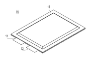
- FIG. 1 is a perspective view showing the appearance of a battery cell
- FIG. 2 is a diagram showing a plan and side surfaces of the battery cell
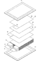
- FIG. 3 is an exploded perspective view of the battery cell.
- the battery cell 10 has a flat rectangular shape, and the positive electrode lead 11 and the negative electrode lead 12 are led out from the same end portion of the exterior material 13.
- the packaging material 13 is, for example, a resin-coated aluminum sheet surface.
- a power generation element (battery element) 15 in which a charge / discharge reaction proceeds and an electrolytic solution are accommodated in the exterior material 13.
- the power generation element 15 is formed by alternately stacking positive electrodes 30 and negative electrodes 40 with a sheet-like separator 20 interposed therebetween. In a state where the power generation element 15 is disposed inside the exterior member 13 and an electrolytic solution is added or the initial charge is performed, air, gas, or the like may accumulate in the battery element 15 (separator 20).
- the positive electrode 30 has a positive electrode active material layer 32 formed on both surfaces of a sheet-like positive electrode current collector.
- the positive electrode active material layer 32 is not formed on the tab portion 34 of the positive electrode 30.
- the tab portions 34 of the positive electrode 30 are provided at overlapping positions when viewed from the stacking direction of the power generation elements 15. The tab portion 34 is connected to the positive electrode lead 11.
- the negative electrode 40 has a negative electrode active material layer 42 formed on both surfaces of a sheet-like negative electrode current collector.
- the negative electrode active material layer 42 is not formed on the tab portion 44 of the negative electrode 40.
- Each tab portion 44 of the negative electrode 40 is provided at a position that overlaps the tab portion 34 of the positive electrode 30 when viewed from the stacking direction of the power generation elements 15.
- the tab portion 44 is connected to the negative electrode lead 12.
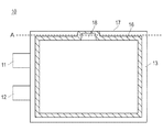
- FIG. 4 is a diagram showing a sealing portion in the battery cell.
- the sealing part 16 shown with the oblique line in the figure is actually invisible from the outside of the battery cell 10, it is clearly shown for explanation of the position.
- the outer packaging material 13 of the battery cell 10 is formed by enclosing a battery element 15 between two rectangular laminate sheets (exterior packaging sheets) and sealing them with a sealing portion 16 along each side of the rectangle. Yes.
- the exterior materials 13 are bonded to each other within a range indicated by oblique lines in FIG.
- the adhesion between the exterior materials 13 can be achieved, for example, by thermally fusing the resins that coat the exterior material 13 or by adhering them with an adhesive.
- the sealing portion 16 is formed to be slightly smaller from a position away from each side of the battery cell 10 by a predetermined distance, that is, from the outer shape of the battery cell 10.
- the sealing portion 16 is formed in a U shape so as to partially approach the side 17 on the side 17 side of the battery cell 10.
- One side of the battery cell 10 is used as a gas vent 18 for discharging air or gas in the exterior material 13.
- the gas vent 18 communicates the interior and exterior of the exterior material 13.
- the gas and the like inside the exterior material 13 are exhausted through the gas vent 18. Thereafter, the battery cell 10 is resealed by bonding the exterior material 13 at the portion of the gas vent 18.
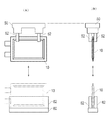
- FIG. 5 is a diagram showing how the battery cells are transported and placed.
- FIG. 5A shows the battery cell 10 viewed from the plane direction
- FIG. 5B shows the battery cell 10 viewed from the arrow 5B direction.
- the battery cell 10 is transported by the transport device 50.
- the transport device 50 of the present embodiment suspends the battery cell 10 and transports it in the air in a state where the rectangular short side of the battery cell 10 stands vertically.
- the transport device 50 is, for example, a transport robot that transports the upper portion of the flat surface of the battery cell 10 by sandwiching the upper portion of the battery cell 10 from both sides by the grip portion 52.
- the transport device 50 transports the battery cell 10 to various processes for processing and processing, and delivers the battery cell 10 to another device or receives it from another device.
- the other device includes, for example, a cradle for temporarily mounting the battery cell 10, a storage device for storing the battery cell 10, and a transport device for transporting the battery cell 10 by a method different from the transport device 50. and so on.
- it may be a processing device or a processing stand for performing predetermined processing on the battery cell 10. Below, the case where the battery cell 10 is delivered to the cradle 60 shown in the lower side in the figure is illustrated.
- the cradle 60 has a support portion 62 that supports the battery cell 10 from both sides.
- the battery cell 10 is transported to above the cradle 60 by the transport device 50, and the battery device 10 is inserted between the support portions 62 of the cradle 60 when the transport device 50 approaches the cradle 60.
- the conveyance device 50 releases the grip by the grip portion 52, the battery cell 10 is stored in the cradle 60.
- the transport device 50 approaches the cradle 60 and grips the battery cell 10 by the grip portion 52.
- the battery cell 10 is taken out from the cradle 60 by raising the transport device 50.
- the battery cell 10 is transported with the gas vent 18 positioned upward, and is stored in the cradle 60 from the side opposite to the gas vent 18. Therefore, the battery cell 10 often comes into contact with other devices such as the cradle 60 on the side opposite to the gas vent 18.
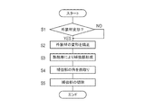
- FIG. 6 is a flowchart showing the procedure of the battery reinforcing method
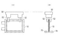
- FIG. 7 is a diagram showing how the battery cell is deformed
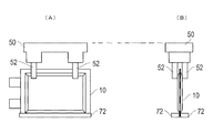
- FIG. 8 is a diagram showing how the reinforcing portion is formed
- FIG. 9 is a reinforcement formed on the battery cell.
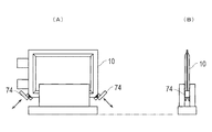
- FIG. 10 is a diagram showing a chamfered state of the reinforcing portion.
- the battery cell 10 is transported to a predetermined position by the transport device 50, and it is confirmed whether or not there is any deformation such as bending at a location where the battery cell 10 is reinforced (step S1).
- the sensor 70 shown in FIG. 7 that inspects the deformation.
- the sensor 70 is, for example, a pair of photoelectric sensors, and the deformation of the exterior material 13 of the battery cell 10 is confirmed by detecting the amount of light irradiated from one side on the other side.
- the exterior material 13 often has a side located on the lower side in the drawing in contact with another device, and is often deformed at a corner. Therefore, for example, it is preferable to detect the bending of the corner portion of the exterior member 13 indicated by the dotted line in FIG.
- step S2 When the bending of the exterior material 13 is detected by the sensor 70 (step S1: YES), the deformation is corrected (step S2).
- the correction of bending is, for example, a pressing roller that extends straight while pressing the exterior member 13.
- the deformation of the exterior material 13 may be corrected by any method.
- step S3 the battery cell 10 is formed with a reinforcing portion (step S3).
- the reinforcing portion as shown in FIG. 8, the lower part of the exterior material 13 of the battery cell 10 is heat-sealed by a heat-sealing device 72.
- the pair of blocks are in contact with a portion forming the reinforcing portion of the exterior material 13, and the resin of the exterior material 13 is fused by pressing while heating from both sides.
- the reinforcement part 80 is formed in the edge
- the sealing portion 16 that seals the exterior material 13 can also be formed by thermal fusion, but the reinforcing portion 80 can be formed by thermal fusion with accuracy different from that of the sealing portion 16.
- the sealing portion 16 is formed by high-precision heat fusion, and the reinforcing portion 80 is formed by relatively low-precision heat fusion.
- the corners of the formed reinforcing portion 80 are chamfered (rounded) (step S4).
- the reinforcing portion 80 is chamfered by a flange 74 as shown in FIG.
- the collar 74 approaches the corner of the battery cell 10 placed on the cradle 60 or the like and cuts off the corner.
- the portions painted black in FIGS. 9 and 10 are cut off.
- step S4 the battery cell 10 is transported to each apparatus for processing and the like, and is taken in and out of the cradle 60 and the storage for supporting the battery cell 10 each time.
- the reinforcing portion 80 is cut off from the battery cell 10 (step S5). The reinforcing portion 80 is cut off at a position indicated by a dotted line B in FIG.
- the reinforcing portion 80 is formed on the other side 19 different from the side 17 provided with the gas vent 18 used for gas discharge.
- the side 19 other than the side 17 often comes into contact with other devices such as the transport device 50 and the cradle 60 when the battery cell 10 is transported or supported for processing. Therefore, by reinforcing the side 19, deformation of the exterior material 13 of the battery cell 10 due to contact with another device can be prevented.
- the reinforcement part 80 can be formed without adding another member, an additional cost is not required for the reinforcement part 80, and a deformation
- a reinforcing portion 80 is formed on the outside. Therefore, the reinforcing portion 80 can be formed with a reference or accuracy different from that of the sealing portion 16. Since the reinforcing portion 80 is formed outside the sealing portion 16, the sealing portion 16 can be protected by the reinforcing portion 80 when the battery cell 10 is transported.
- the formation of the sealing portion 16 and the reinforcing portion 80 can be achieved by thermally fusing the resin of the laminate sheet separately, so that the sealing portion 16 and the reinforcing portion 80 are separately used while using the laminate sheet having the same configuration. Can be formed.
- the deformation of the exterior material 13 is detected by the sensor 70 before the reinforcing portion 80 is formed, the deformation of the side can be reliably detected.
- the reinforcing portion 80 is formed on the side 19 of the battery cell 10 that comes into contact with another device such as the cradle 60, deformation of the exterior material 13 of the battery cell 10 due to contact with the other device can be prevented.
- the corner of the side 19 reinforced by the reinforcing portion 80 is chamfered, when the battery cell 10 is inserted from the side 19 where the battery cell 10 is reinforced into another device such as the cradle 60, the load on the corner is dispersed and the side 19 is deformed. Can be prevented.
- the reinforcing portion 80 is provided to prevent the outer packaging material 13 of the battery cell 10 from being deformed, while the reinforcing portion 80 is finally cut off. Therefore, the reinforcing portion 80 that is reinforced by a process such as processing and has some damage does not remain in the battery cell 10 as the final product. Therefore, the battery cell 10 without any scratches can be obtained.
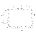
- FIG. 11 is a view showing a battery cell in which a reinforcing portion is further formed.
- the reinforcing portion 80 is formed along the side 19 of the battery cell 10.
- the reinforcing portions 81 and 82 may be formed on the vertically standing side.
- the reinforcing portions 81 and 82 are formed in the same manner as described above.
- the reinforcing portions 81 and 82 are formed by heat-sealing a resin of a laminate sheet. Note that the reinforcing portion 81 can be cut off at the position indicated by the dotted line C before the battery cell 10 is shipped. In FIG.
- the reinforcing portion 82 is also formed on the side where the positive electrode lead 11 and the negative electrode lead 12 are drawn, but the reinforcing portion 82 cannot be excised and is left as it is. Since there is the positive electrode lead 11 and the like on the reinforcing portion 82 side, the reinforcing portion 82 is not damaged so much, and there is no problem even if the reinforcing portion 82 is left.
- the said embodiment demonstrated the example which mounts the battery cell 10 in the cradle 60, and takes out the battery cell 10 from the cradle 60, it is not limited to this.
- the reinforcement of the battery cell 10 is also effective when the battery cell 10 is delivered to a storage rack that stores a plurality of battery cells 10 or the battery cell is taken out from the storage rack.
Landscapes
- Chemical & Material Sciences (AREA)
- Chemical Kinetics & Catalysis (AREA)
- Electrochemistry (AREA)
- General Chemical & Material Sciences (AREA)
- Inorganic Chemistry (AREA)
- Sealing Battery Cases Or Jackets (AREA)
Priority Applications (3)
| Application Number | Priority Date | Filing Date | Title |
|---|---|---|---|
| US14/376,649 US9553285B2 (en) | 2012-02-13 | 2013-02-13 | Battery reinforcement method |
| EP13748485.3A EP2816631B1 (en) | 2012-02-13 | 2013-02-13 | Battery reinforcement method |
| CN201380008850.XA CN104115302B (zh) | 2012-02-13 | 2013-02-13 | 电池加强方法 |
Applications Claiming Priority (2)
| Application Number | Priority Date | Filing Date | Title |
|---|---|---|---|
| JP2012028515A JP5909378B2 (ja) | 2012-02-13 | 2012-02-13 | 電池補強方法 |
| JP2012-028515 | 2012-02-13 |
Publications (1)
| Publication Number | Publication Date |
|---|---|
| WO2013122097A1 true WO2013122097A1 (ja) | 2013-08-22 |
Family
ID=48984206
Family Applications (1)
| Application Number | Title | Priority Date | Filing Date |
|---|---|---|---|
| PCT/JP2013/053381 Ceased WO2013122097A1 (ja) | 2012-02-13 | 2013-02-13 | 電池補強方法 |
Country Status (5)
| Country | Link |
|---|---|
| US (1) | US9553285B2 (enExample) |
| EP (1) | EP2816631B1 (enExample) |
| JP (1) | JP5909378B2 (enExample) |
| CN (1) | CN104115302B (enExample) |
| WO (1) | WO2013122097A1 (enExample) |
Families Citing this family (2)
| Publication number | Priority date | Publication date | Assignee | Title |
|---|---|---|---|---|
| US9837682B1 (en) | 2016-08-29 | 2017-12-05 | Microsoft Technology Licensing, Llc | Variable layer thickness in curved battery cell |
| KR102779619B1 (ko) * | 2020-11-09 | 2025-03-10 | 주식회사 엘지에너지솔루션 | 이차 전지 |
Citations (5)
| Publication number | Priority date | Publication date | Assignee | Title |
|---|---|---|---|---|
| JPH07183357A (ja) | 1993-12-22 | 1995-07-21 | Dainippon Screen Mfg Co Ltd | 基板配列ピッチ変換装置 |
| JP2005347123A (ja) * | 2004-06-03 | 2005-12-15 | Toshiba Corp | 薄型非水電解質二次電池 |
| WO2006098242A1 (ja) * | 2005-03-17 | 2006-09-21 | Nec Corporation | フィルム外装電気デバイスおよびその製造方法 |
| JP2010198988A (ja) * | 2009-02-26 | 2010-09-09 | Sumitomo Chemical Co Ltd | フィルムケース型蓄電デバイス |
| JP2012204002A (ja) * | 2011-03-23 | 2012-10-22 | Nec Tokin Corp | 蓄電デバイス |
Family Cites Families (7)
| Publication number | Priority date | Publication date | Assignee | Title |
|---|---|---|---|---|
| GB2087779B (en) * | 1980-11-20 | 1985-05-15 | Rhodes Joseph Ltd | Metal trimmer |
| JP3709134B2 (ja) * | 2000-11-22 | 2005-10-19 | 松下電器産業株式会社 | 角形電池 |
| WO2005108945A1 (en) * | 2004-05-12 | 2005-11-17 | Pirelli Tyre S.P.A. | Method for determining a force at the hub of a wheel of a vehicle whilst traveling and wheel suitable for allowing said method to be carried out |
| JP5108411B2 (ja) * | 2007-08-03 | 2012-12-26 | パナソニック株式会社 | 電池缶およびその製造方法並びに製造装置 |
| US20090169977A1 (en) * | 2007-12-31 | 2009-07-02 | Apple Inc. | Systems and methods for monitoring and responding to forces influencing a battery |
| DE102008047615A1 (de) * | 2008-09-17 | 2010-04-15 | Li-Tec Battery Gmbh | Akkumulator |
| US8771866B2 (en) * | 2010-03-30 | 2014-07-08 | Samsung Sdi Co., Ltd. | Pouch type secondary battery and the fabrication method thereof |
-
2012
- 2012-02-13 JP JP2012028515A patent/JP5909378B2/ja active Active
-
2013
- 2013-02-13 US US14/376,649 patent/US9553285B2/en active Active
- 2013-02-13 WO PCT/JP2013/053381 patent/WO2013122097A1/ja not_active Ceased
- 2013-02-13 EP EP13748485.3A patent/EP2816631B1/en active Active
- 2013-02-13 CN CN201380008850.XA patent/CN104115302B/zh active Active
Patent Citations (5)
| Publication number | Priority date | Publication date | Assignee | Title |
|---|---|---|---|---|
| JPH07183357A (ja) | 1993-12-22 | 1995-07-21 | Dainippon Screen Mfg Co Ltd | 基板配列ピッチ変換装置 |
| JP2005347123A (ja) * | 2004-06-03 | 2005-12-15 | Toshiba Corp | 薄型非水電解質二次電池 |
| WO2006098242A1 (ja) * | 2005-03-17 | 2006-09-21 | Nec Corporation | フィルム外装電気デバイスおよびその製造方法 |
| JP2010198988A (ja) * | 2009-02-26 | 2010-09-09 | Sumitomo Chemical Co Ltd | フィルムケース型蓄電デバイス |
| JP2012204002A (ja) * | 2011-03-23 | 2012-10-22 | Nec Tokin Corp | 蓄電デバイス |
Non-Patent Citations (1)
| Title |
|---|
| See also references of EP2816631A4 |
Also Published As
| Publication number | Publication date |
|---|---|
| JP5909378B2 (ja) | 2016-04-26 |
| EP2816631A1 (en) | 2014-12-24 |
| JP2013165038A (ja) | 2013-08-22 |
| CN104115302A (zh) | 2014-10-22 |
| EP2816631A4 (en) | 2015-07-29 |
| EP2816631B1 (en) | 2021-03-24 |
| US9553285B2 (en) | 2017-01-24 |
| CN104115302B (zh) | 2017-12-01 |
| US20150026969A1 (en) | 2015-01-29 |
Similar Documents
| Publication | Publication Date | Title |
|---|---|---|
| KR101719030B1 (ko) | 필름 외장 전지 및 그 선별 방법 | |
| EP3588653B1 (en) | Method for producing mono-cell | |
| CN104364955B (zh) | 用隔膜夹持极板的装置 | |
| KR102757891B1 (ko) | 전극 조립체 제조방법과 전극 조립체 제조장치 | |
| TWI472080B (zh) | A position detecting device and a position detecting method | |
| JP6481258B2 (ja) | 電気デバイスのセパレータ接合方法、電気デバイスのセパレータ接合装置、および電気デバイス | |
| JP5291811B2 (ja) | 2次電池の製造方法および製造装置 | |
| JP6597029B2 (ja) | 積層装置 | |
| JP6638593B2 (ja) | 電極組立体の製造方法 | |
| CN105552387A (zh) | 制造膜电极组件的设备及使用其制造的膜电极组件 | |
| WO2012070297A1 (ja) | 極板包装装置 | |
| KR20190045602A (ko) | 이차전지용 라미네이션 장치 및 방법 | |
| CN111180780B (zh) | 用于制造片状电极的堆叠体的设备 | |
| WO2012137903A1 (ja) | 袋詰電極の製造装置、および袋詰電極の製造方法 | |
| JP6642072B2 (ja) | 二次電池の製造装置および二次電池の製造方法 | |
| US20210013481A1 (en) | Battery Stack Forming Apparatus and Battery Stack Forming Method | |
| JPWO2018116543A1 (ja) | 電極積層体の製造装置 | |
| WO2020110207A1 (ja) | 位置決め搬送装置および位置決め搬送方法 | |
| CN107646153A (zh) | 用于电池组的片附接装置 | |
| JP5909378B2 (ja) | 電池補強方法 | |
| KR101504859B1 (ko) | 접합 장치 및 접합 방법 | |
| JP6044635B2 (ja) | 基板用包装ならびにそのような包装を備える包装ユニット | |
| JP6075256B2 (ja) | 電極の製造方法及び電極の製造装置 | |
| JP6575940B2 (ja) | 袋詰電極の製造装置、および袋詰電極の製造方法 | |
| WO2018127994A1 (ja) | 電極体の製造方法 |
Legal Events
| Date | Code | Title | Description |
|---|---|---|---|
| 121 | Ep: the epo has been informed by wipo that ep was designated in this application |
Ref document number: 13748485 Country of ref document: EP Kind code of ref document: A1 |
|
| DPE1 | Request for preliminary examination filed after expiration of 19th month from priority date (pct application filed from 20040101) | ||
| WWE | Wipo information: entry into national phase |
Ref document number: 2013748485 Country of ref document: EP |
|
| WWE | Wipo information: entry into national phase |
Ref document number: 14376649 Country of ref document: US |
|
| NENP | Non-entry into the national phase |
Ref country code: DE |