WO2013121962A1 - Diesel engine - Google Patents
Diesel engine Download PDFInfo
- Publication number
- WO2013121962A1 WO2013121962A1 PCT/JP2013/052827 JP2013052827W WO2013121962A1 WO 2013121962 A1 WO2013121962 A1 WO 2013121962A1 JP 2013052827 W JP2013052827 W JP 2013052827W WO 2013121962 A1 WO2013121962 A1 WO 2013121962A1
- Authority
- WO
- WIPO (PCT)
- Prior art keywords
- cylinder
- engine
- reduced
- turbocharger
- intake
- Prior art date
Links
Images


Classifications
-
- F—MECHANICAL ENGINEERING; LIGHTING; HEATING; WEAPONS; BLASTING
- F02—COMBUSTION ENGINES; HOT-GAS OR COMBUSTION-PRODUCT ENGINE PLANTS
- F02D—CONTROLLING COMBUSTION ENGINES
- F02D13/00—Controlling the engine output power by varying inlet or exhaust valve operating characteristics, e.g. timing
- F02D13/02—Controlling the engine output power by varying inlet or exhaust valve operating characteristics, e.g. timing during engine operation
- F02D13/0203—Variable control of intake and exhaust valves
-
- F—MECHANICAL ENGINEERING; LIGHTING; HEATING; WEAPONS; BLASTING
- F02—COMBUSTION ENGINES; HOT-GAS OR COMBUSTION-PRODUCT ENGINE PLANTS
- F02B—INTERNAL-COMBUSTION PISTON ENGINES; COMBUSTION ENGINES IN GENERAL
- F02B37/00—Engines characterised by provision of pumps driven at least for part of the time by exhaust
- F02B37/001—Engines characterised by provision of pumps driven at least for part of the time by exhaust using exhaust drives arranged in parallel
-
- F—MECHANICAL ENGINEERING; LIGHTING; HEATING; WEAPONS; BLASTING
- F02—COMBUSTION ENGINES; HOT-GAS OR COMBUSTION-PRODUCT ENGINE PLANTS
- F02B—INTERNAL-COMBUSTION PISTON ENGINES; COMBUSTION ENGINES IN GENERAL
- F02B37/00—Engines characterised by provision of pumps driven at least for part of the time by exhaust
- F02B37/004—Engines characterised by provision of pumps driven at least for part of the time by exhaust with exhaust drives arranged in series
-
- F—MECHANICAL ENGINEERING; LIGHTING; HEATING; WEAPONS; BLASTING
- F02—COMBUSTION ENGINES; HOT-GAS OR COMBUSTION-PRODUCT ENGINE PLANTS
- F02B—INTERNAL-COMBUSTION PISTON ENGINES; COMBUSTION ENGINES IN GENERAL
- F02B37/00—Engines characterised by provision of pumps driven at least for part of the time by exhaust
- F02B37/007—Engines characterised by provision of pumps driven at least for part of the time by exhaust with exhaust-driven pumps arranged in parallel, e.g. at least one pump supplying alternatively
-
- F—MECHANICAL ENGINEERING; LIGHTING; HEATING; WEAPONS; BLASTING
- F02—COMBUSTION ENGINES; HOT-GAS OR COMBUSTION-PRODUCT ENGINE PLANTS
- F02B—INTERNAL-COMBUSTION PISTON ENGINES; COMBUSTION ENGINES IN GENERAL
- F02B37/00—Engines characterised by provision of pumps driven at least for part of the time by exhaust
- F02B37/013—Engines characterised by provision of pumps driven at least for part of the time by exhaust with exhaust-driven pumps arranged in series
-
- F—MECHANICAL ENGINEERING; LIGHTING; HEATING; WEAPONS; BLASTING
- F02—COMBUSTION ENGINES; HOT-GAS OR COMBUSTION-PRODUCT ENGINE PLANTS
- F02B—INTERNAL-COMBUSTION PISTON ENGINES; COMBUSTION ENGINES IN GENERAL
- F02B37/00—Engines characterised by provision of pumps driven at least for part of the time by exhaust
- F02B37/12—Control of the pumps
- F02B37/16—Control of the pumps by bypassing charging air
-
- F—MECHANICAL ENGINEERING; LIGHTING; HEATING; WEAPONS; BLASTING
- F02—COMBUSTION ENGINES; HOT-GAS OR COMBUSTION-PRODUCT ENGINE PLANTS
- F02B—INTERNAL-COMBUSTION PISTON ENGINES; COMBUSTION ENGINES IN GENERAL
- F02B37/00—Engines characterised by provision of pumps driven at least for part of the time by exhaust
- F02B37/12—Control of the pumps
- F02B37/22—Control of the pumps by varying cross-section of exhaust passages or air passages, e.g. by throttling turbine inlets or outlets or by varying effective number of guide conduits
-
- F—MECHANICAL ENGINEERING; LIGHTING; HEATING; WEAPONS; BLASTING
- F02—COMBUSTION ENGINES; HOT-GAS OR COMBUSTION-PRODUCT ENGINE PLANTS
- F02B—INTERNAL-COMBUSTION PISTON ENGINES; COMBUSTION ENGINES IN GENERAL
- F02B37/00—Engines characterised by provision of pumps driven at least for part of the time by exhaust
- F02B37/12—Control of the pumps
- F02B37/24—Control of the pumps by using pumps or turbines with adjustable guide vanes
-
- F—MECHANICAL ENGINEERING; LIGHTING; HEATING; WEAPONS; BLASTING
- F02—COMBUSTION ENGINES; HOT-GAS OR COMBUSTION-PRODUCT ENGINE PLANTS
- F02D—CONTROLLING COMBUSTION ENGINES
- F02D13/00—Controlling the engine output power by varying inlet or exhaust valve operating characteristics, e.g. timing
- F02D13/02—Controlling the engine output power by varying inlet or exhaust valve operating characteristics, e.g. timing during engine operation
- F02D13/06—Cutting-out cylinders
-
- F—MECHANICAL ENGINEERING; LIGHTING; HEATING; WEAPONS; BLASTING
- F02—COMBUSTION ENGINES; HOT-GAS OR COMBUSTION-PRODUCT ENGINE PLANTS
- F02D—CONTROLLING COMBUSTION ENGINES
- F02D17/00—Controlling engines by cutting out individual cylinders; Rendering engines inoperative or idling
- F02D17/02—Cutting-out
-
- F—MECHANICAL ENGINEERING; LIGHTING; HEATING; WEAPONS; BLASTING
- F02—COMBUSTION ENGINES; HOT-GAS OR COMBUSTION-PRODUCT ENGINE PLANTS
- F02D—CONTROLLING COMBUSTION ENGINES
- F02D23/00—Controlling engines characterised by their being supercharged
-
- F—MECHANICAL ENGINEERING; LIGHTING; HEATING; WEAPONS; BLASTING
- F02—COMBUSTION ENGINES; HOT-GAS OR COMBUSTION-PRODUCT ENGINE PLANTS
- F02D—CONTROLLING COMBUSTION ENGINES
- F02D41/00—Electrical control of supply of combustible mixture or its constituents
- F02D41/0002—Controlling intake air
- F02D41/0007—Controlling intake air for control of turbo-charged or super-charged engines
-
- F—MECHANICAL ENGINEERING; LIGHTING; HEATING; WEAPONS; BLASTING
- F02—COMBUSTION ENGINES; HOT-GAS OR COMBUSTION-PRODUCT ENGINE PLANTS
- F02D—CONTROLLING COMBUSTION ENGINES
- F02D41/00—Electrical control of supply of combustible mixture or its constituents
- F02D41/008—Controlling each cylinder individually
- F02D41/0082—Controlling each cylinder individually per groups or banks
-
- F—MECHANICAL ENGINEERING; LIGHTING; HEATING; WEAPONS; BLASTING
- F02—COMBUSTION ENGINES; HOT-GAS OR COMBUSTION-PRODUCT ENGINE PLANTS
- F02M—SUPPLYING COMBUSTION ENGINES IN GENERAL WITH COMBUSTIBLE MIXTURES OR CONSTITUENTS THEREOF
- F02M26/00—Engine-pertinent apparatus for adding exhaust gases to combustion-air, main fuel or fuel-air mixture, e.g. by exhaust gas recirculation [EGR] systems
- F02M26/02—EGR systems specially adapted for supercharged engines
- F02M26/08—EGR systems specially adapted for supercharged engines for engines having two or more intake charge compressors or exhaust gas turbines, e.g. a turbocharger combined with an additional compressor
-
- F—MECHANICAL ENGINEERING; LIGHTING; HEATING; WEAPONS; BLASTING
- F01—MACHINES OR ENGINES IN GENERAL; ENGINE PLANTS IN GENERAL; STEAM ENGINES
- F01N—GAS-FLOW SILENCERS OR EXHAUST APPARATUS FOR MACHINES OR ENGINES IN GENERAL; GAS-FLOW SILENCERS OR EXHAUST APPARATUS FOR INTERNAL COMBUSTION ENGINES
- F01N2900/00—Details of electrical control or of the monitoring of the exhaust gas treating apparatus
- F01N2900/06—Parameters used for exhaust control or diagnosing
- F01N2900/16—Parameters used for exhaust control or diagnosing said parameters being related to the exhaust apparatus, e.g. particulate filter or catalyst
- F01N2900/1612—SOx amount trapped in catalyst
-
- F—MECHANICAL ENGINEERING; LIGHTING; HEATING; WEAPONS; BLASTING
- F02—COMBUSTION ENGINES; HOT-GAS OR COMBUSTION-PRODUCT ENGINE PLANTS
- F02D—CONTROLLING COMBUSTION ENGINES
- F02D41/00—Electrical control of supply of combustible mixture or its constituents
- F02D41/0002—Controlling intake air
- F02D2041/001—Controlling intake air for engines with variable valve actuation
- F02D2041/0012—Controlling intake air for engines with variable valve actuation with selective deactivation of cylinders
-
- Y—GENERAL TAGGING OF NEW TECHNOLOGICAL DEVELOPMENTS; GENERAL TAGGING OF CROSS-SECTIONAL TECHNOLOGIES SPANNING OVER SEVERAL SECTIONS OF THE IPC; TECHNICAL SUBJECTS COVERED BY FORMER USPC CROSS-REFERENCE ART COLLECTIONS [XRACs] AND DIGESTS
- Y02—TECHNOLOGIES OR APPLICATIONS FOR MITIGATION OR ADAPTATION AGAINST CLIMATE CHANGE
- Y02T—CLIMATE CHANGE MITIGATION TECHNOLOGIES RELATED TO TRANSPORTATION
- Y02T10/00—Road transport of goods or passengers
- Y02T10/10—Internal combustion engine [ICE] based vehicles
- Y02T10/12—Improving ICE efficiencies
Definitions
- the present invention relates to a diesel engine provided with a reduced-cylinder operation system provided with a valve suspension mechanism for temporarily stopping an intake / exhaust valve in addition to a turbo-type supercharging system.
- the internal combustion engine is roughly divided into a gasoline engine and a diesel engine depending on the fuel used. Since gasoline engines have lower thermal efficiency and lower fuel consumption than diesel engines, research and development on improving thermal efficiency has been conducted to improve this, and various measures such as reducing engine friction by changing intake and exhaust valve mechanisms and auxiliary devices. Device development is progressing rapidly.
- Another method is a method of reducing the friction of the engine body and the engine auxiliary machine, which has already been actively performed in a gasoline engine, and the development of similar devices related to this method is also progressing in a diesel engine. There are various types of friction, but nearly half of this is engine pumping loss.
- the illustrated work of an engine is generally indicated by a “PV diagram” in which the pressure in the engine cylinder is the volume in the engine cylinder (cm 3 : horizontal axis) and the pressure in the engine cylinder (MPa: vertical axis). .
- the pumping loss of the engine is a region on the lower side of this “PV diagram”, and the area of this region is the loss work. In other words, after the engine burns, the engine rises during the exhaust stroke in which the piston rises and the exhaust valve opens to push out the exhaust gas in the cylinder, and during the intake stroke in which the piston descends and the intake valve opens to introduce new air into the cylinder. The generated friction is the pumping loss (pumping loss).
- some gasoline engine vehicles have already adopted a reduced-cylinder operation system that improves fuel efficiency by reducing pumping loss.
- fuel consumption is improved by reducing the number of cylinders to be operated by stopping some intake / exhaust valves depending on the operating state of the engine, thereby reducing the pumping loss as a whole cylinder.
- the line on the “PV diagram” is substantially a single line, and the area of the pumping loss is substantially zero. As a result, the fuel efficiency of the engine can be greatly improved.
- the stopped cylinder in this reduced-cylinder operation system normally stops 2 cylinders in the case of 4 cylinders, and in the case of 6 cylinders It is common to deactivate three cylinders. For example, if half of the cylinders are stopped at a light load where the turbocharger is not operating sufficiently, the exhaust gas flow rate of the engine will also be approximately halved and will shift greatly to the left on the turbo map.
- turbo compressor map indicated by the gas flow rate (horizontal axis) and the pressure ratio of the turbo inlet and outlet (vertical axis)
- the turbo compressor map indicated by the gas flow rate (horizontal axis) and the pressure ratio of the turbo inlet and outlet (vertical axis)
- it is in the region that does not operate as a turbocharger at the bottom and leftmost position. storm in. Accordingly, even if the fuel is increased slightly from this state and the engine load is increased, sufficient turbocharging by the turbo-type supercharger cannot be obtained, so that it is not possible to improve the fuel consumption of the engine.
- Patent Document 1 Japanese Patent Application Laid-Open No. 2010-2223040 (Patent Document 1), even if the reduced cylinder operation is performed with the turbocharged engine, the turbocharger is hindered.
- the low-pressure EGR loop and the high-pressure EGR loop are provided so that the exhaust gas can be continuously recirculated, and the exhaust gas is selected by selecting the low-pressure EGR loop so that the entire amount of exhaust gas passes through the turbocharger during reduced-cylinder operation.
- a high-pressure EGR loop or a high-pressure EGR loop and a low-pressure EGR loop are selected during normal operation, and an exhaust gas recirculation method and apparatus for a turbocharged engine that recirculates exhaust gas is proposed. Yes.
- Patent Document 2 a base turbocharger is used to improve the shortage of the supercharging amount of the operating cylinder by adopting the reduced cylinder system.
- Patent Document 2 an engine that employs a small turbocharger and mounts a plurality of turbochargers has been proposed.
- this engine has a problem that engine performance, particularly fuel consumption, in a full load operation region other than reduced-cylinder operation deteriorates.
- large diesel engines generally have better fuel efficiency than small diesel engines because of the greater influence of the difference in turbo efficiency.
- This turbo efficiency is generally much larger for large turbochargers than for small turbochargers.
- the area is also large. Therefore, this engine can improve the shortage of supercharging amount that occurs during reduced-cylinder operation, but on the other hand, the engine performance that is based on the engine performance that is based on full-cylinder operation at full load is reduced by installing a small turbo. Performance, especially fuel efficiency, will be deteriorated.
- Fig. 7 shows the graphs of "engine speed and engine output” and “compressor map (air flow rate and pressure ratio)" reflecting the image of a normal engine system of a single-stage supercharging system.
- Fig. 8 shows a graph of "engine speed and engine output” and “compressor map (air flow rate and pressure ratio)", which is an image of the engine of the reduced cylinder operation and the system of two small turbochargers in Patent Document 2. A graph is shown.
- the turbocharger can also be used for specification selection and matching, but as mentioned above, the efficient area that is the merit of adopting a small turbocharger is narrow, and the small turbocharger Since the efficiency of the charger is lower than that of a large turbocharger, the efficiency cannot be increased in a high load region. For this reason, it is difficult to employ a commercial vehicle (CV vehicle) or the like because the fuel efficiency is deteriorated in a high-load region frequently used.
- CV vehicle commercial vehicle
- a high-pressure stage turbocharger is disposed in each of a plurality of exhaust passages, and these high-pressure turbochargers are arranged.
- this internal combustion engine has two problems: the structural problem of the three-way valve and the deterioration of the turbo durability due to the mounting position.
- the valve of the three-way valve is half open, but the opening area of this valve portion is very narrow.
- the action of closing the valve of the three-way valve to one side by the pressure difference that occurs when returning from reduced cylinder operation to base full cylinder operation, or when the engine combustion or turbo performance varies, as a result The engine pumping loss is worsened by an increase in the exhaust pressure of the engine cylinders of the low pressure group, so that the engine performance such as exhaust gas performance and fuel consumption performance is degraded. As a result, the system performance cannot be improved.
- the mounting location of the three-way valve is the high-pressure stage turbo outlet.
- the high-pressure stage turbo outlet For example, when one of the cylinder groups suddenly enters the reduced-cylinder operation region while the high-pressure turbocharger is operating near maximum speed while the engine is operating at full load, The fuel is stopped, the intake and exhaust valves are stopped at the same time, and the other cylinder group operates in a reduced cylinder, but the exhaust energy obtained by the high-pressure stage turbocharger on the reduced cylinder operation side decreases, so the pressure of the compressed air decreases. As a result, the three-way valve closes rapidly.
- the present invention has been made in view of the above situation, and an object of the present invention is to provide a plurality of small high-pressure turbochargers optimized for the respective intake systems of the cylinder group to be reduced and the cylinder group to be continuously operated. In addition, it has a large low-pressure stage turbo that does not deteriorate the engine base full load performance, and can improve the supercharging circulation between the small high-pressure stage turbocharger during reduced-cylinder operation. It is an object of the present invention to provide a diesel engine that can sufficiently obtain an effect and improve an engine performance such as fuel efficiency.
- a diesel engine includes a turbocharger and a valve deactivation mechanism for reducing cylinders that stops opening and closing of an exhaust valve and an intake valve of a preset cylinder group.
- a first cylinder group that continues or stops operation by the valve deactivation mechanism and a second cylinder group that deactivates or continues operation by the reduced-cylinder valve deactivation mechanism, and separates the intake passage to the first cylinder group
- the first intake passage and the second intake passage to the second cylinder group are branched, and the exhaust passage is branched to the first exhaust passage from the first cylinder group and the second exhaust passage from the second cylinder group.
- a first turbocharger is provided in one intake passage and the first exhaust passage
- a second turbocharger is provided in the second intake passage and the second exhaust passage, respectively, and the first intake passage and the first exhaust passage are provided.
- An intake passage on the upstream side of a branch portion with the two intake passages, and the first In a diesel engine provided with a third turbo-type supercharger in an exhaust passage on the downstream side of a joining portion between an air passage and the second exhaust passage, the first intake passage and the second intake passage are joined together Rather, the first intake passage is connected to the first intake manifold of the first cylinder group, and the second intake passage is connected to the second intake manifold of the second cylinder group.
- the reduced-cylinder operation system can stop the intake / exhaust valve of the engine, reduce the pumping friction of the engine, and improve fuel efficiency.
- This reduced-cylinder operation system stops the intake and exhaust valves of the engine according to the engine load and deactivates some cylinders, thereby reducing the intake and exhaust pumping loss of the engine and at the same time
- the fuel injection amount is increased, the load is increased, the average effective pressure (PME) of the operating cylinder is increased, and the thermal efficiency is increased due to the reduction of heat loss. As a result, the fuel efficiency of the engine is improved.
- turbocharger that is optimized for the exhaust gas flow rate of the cylinder that is operating when the cylinder is reduced, and the turbocharger is optimized for the reduced cylinder operation system.
- a feeder can be placed.
- the turbocharger can operate on a highly efficient operation line and contribute to improvement in engine fuel consumption.
- high operating efficiency can be achieved in the operating cylinder, and finally fuel efficiency can be improved in engine performance.
- the reduced-cylinder operation significantly reduces the exhaust flow rate and shifts the operating point of the turbocharger.
- the turbocharger cannot perform sufficient work, and the engine supercharging amount It is possible to prevent the deterioration of the engine and the combustion of the engine from deteriorating and the fuel economy from deteriorating and the overall fuel efficiency performance from deteriorating.
- the turbocharger keeps the turbo operating point well and works well, keeps the engine supercharged, keeps engine combustion well, and fuel economy Can be suppressed.
- first intake passage is connected to the first intake manifold of the first cylinder group without joining the first intake passage and the second intake passage
- the second intake passage is connected to the second intake manifold of the second cylinder group.
- the reduced cylinder valve deactivation mechanism during normal operation, the reduced cylinder valve deactivation mechanism, the first turbocharger, the second turbocharger, and the first engine according to the engine speed and the engine load.
- control is performed such that the deactivation of the cylinder group that has been deactivated is stopped and all the cylinders are activated.
- the valve deactivation mechanism for reducing cylinders is controlled by the basic map or feedback control according to the engine speed and engine load (or fuel amount or engine output). Can be optimized. Also, during idle operation, all cylinders can be operated to reduce engine vibration, and during deceleration operation and when the fuel amount is zero, all cylinders can be operated to ensure normal engine braking force. By adopting the reduced-cylinder operation system, it is possible to prevent a decrease in engine braking force that becomes a problem.
- the engine base full load performance is further deteriorated together with a plurality of small high-pressure turbochargers optimized for the intake system of the cylinder group to be reduced and the cylinder group to be continuously operated. Equipped with a large-sized low-pressure stage turbocharger that does not allow it to improve the supercharging circulation between the small high-pressure stage turbocharger during reduced-cylinder operation, and achieves the effect of reduced-cylinder operation sufficiently with a diesel engine, fuel consumption, etc.
- the engine performance improvement effect can be obtained.
- first intake passage is connected to the first intake manifold of the first cylinder group without joining the first intake passage and the second intake passage
- the second intake passage is connected to the second intake manifold of the second cylinder group.
- FIG. 1 is a diagram showing a configuration of a diesel engine according to an embodiment of the present invention.
- FIG. 2 is a diagram showing a control-related configuration of the diesel engine of FIG.
- FIG. 3 is a diagram illustrating an example of a control flow of the turbocharging system and the reduced-cylinder operation system.
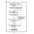
- FIG. 4 is a diagram showing an example of a detailed control flow of the reduced-cylinder operation of FIG.
- FIG. 5 is a diagram illustrating an example of the all-cylinder operation region, the reduced-cylinder operation region, and the reduced-cylinder operation non-operation region using the engine speed and the engine output as parameters.
- FIG. 6 is a diagram showing an example of a basic map of boost pressure using the engine speed and the fuel amount as parameters.
- FIG. 1 is a diagram showing a configuration of a diesel engine according to an embodiment of the present invention.
- FIG. 2 is a diagram showing a control-related configuration of the diesel engine of FIG.
- FIG. 3 is a diagram illustrating an example of a control
- FIG. 7 is a diagram showing a graph of “engine speed and engine output” and a graph of “compressor map (air flow rate and pressure ratio)” in the image of a normal engine system of a conventional one-stage supercharging system.
- Fig. 8 is a graph of "engine speed and engine output” and “compressor map (air flow rate and pressure ratio)", which is an image of a system of a conventional engine with a reduced-cylinder operation and two small turbochargers.
- FIG. FIG. 9 is a graph showing an “engine speed and engine output” graph and an “compressor map (air flow rate and pressure ratio)” image of an engine that performs the reduced-cylinder operation of the conventional two-stage supercharging method. is there.
- a diesel engine (hereinafter referred to as an engine) 1 includes a first cylinder group that continues (or pauses) operation by a valve reduction mechanism 21 for reducing cylinders, and a cylinder for reduction cylinders.
- the second cylinder group that is deactivated (or continued) by the valve deactivation mechanism 21 is configured separately.
- the intake manifold is formed of a first intake manifold 11Aa for the first cylinder group and a second intake manifold 11Ba for the second cylinder group, and the exhaust manifold is also the first intake manifold 11Ba for the first cylinder group.
- the intake passage 12 is branched downstream of the air cleaner 15 and the low pressure compressor 26a of the low pressure supercharger 26 into a first intake passage 12A to the first cylinder group and a second intake passage 12B to the second cylinder group.
- the exhaust passage 13 is branched into a first exhaust passage 13A from the first cylinder group and a second exhaust passage 13B from the second cylinder group, and the exhaust passage is upstream of the low-pressure turbine 26b of the low-pressure supercharger 26. 13 to join.
- the intake passage 12 that is upstream of the branch portion between the first intake passage 12A and the second intake passage 12B, and the exhaust that is downstream of the junction portion of the first exhaust passage 13A and the second exhaust passage 13B.
- a low-pressure stage supercharger 26 serving as a third turbocharger is disposed. With this configuration, the engine supercharging performance is improved.
- a first turbocharger 16A is provided in the first intake passage 12A and the first exhaust passage 13A
- a second turbocharger 16B is provided in the second intake passage 12B and the second exhaust passage 13B. That is, the first compressor 16Aa of the first turbocharger 16A is provided in the first intake passage 12A, the first turbine 16Ab of the first turbocharger 16A is provided in the first exhaust passage 13A, and the second intake air is provided.
- a second compressor 16Ba of the second turbocharger 16B is provided in the passage 12B, and a second turbine 16Bb of the second turbocharger 16B is provided in the second exhaust passage 13B.
- the first turbocharger 16A and the low-pressure stage supercharger 26, or the second turbocharger 16B and the low-pressure stage supercharger 26, the two-stage turbocharger system is realized.
- the first and second turbochargers 16A and 16B are preferably VGT turbo engines having variable blades in the turbines 16Ab and 16Bb.
- first intercooler 17A is disposed downstream of the first compressor 16Aa of the first turbocharger 16A in the first intake passage 12A, and the second compressor 16Ba of the second turbocharger 16B in the second intake passage 12B.
- the second intercooler 17B is provided on the downstream side of each.
- first intake passage 12A in the first cylinder group is connected to the first intake passage 12A without joining the first intake passage 12A on the downstream side of the first intercooler 17A and the second intake passage 12B on the downstream side of the second intercooler 17B.
- the second intake passage 12B is connected to the manifold 11Aa and connected to the second intake manifold 11Ba of the second cylinder group.
- first EGR passage 14A that connects the first exhaust passage 13A and the first intake passage 12A
- second EGR passage 14B that connects the second exhaust passage 13B and the second intake passage 12B
- first EGR passage 14A Includes a first EGR cooler 18A, a first EGR valve 19A, and a first EGR check valve 20A
- a second EGR passage 14B includes a second EGR cooler 18B, a second EGR valve 19B, and a second EGR check valve 20B.
- the engine body 11 is provided with a cylinder deactivation valve deactivation mechanism 21 that is operated, for example, hydraulically, in each cylinder of the engine 1 so that the cylinder deactivation operation can be performed.
- a hydraulic cylinder valve 22 for reducing cylinder control is provided.
- this reduced cylinder valve deactivation mechanism 21 the opening / closing valve operation of an intake / exhaust valve (not shown) of the engine 1 is deactivated, and some cylinders of the engine 1 can be arbitrarily deactivated. That is, a reduced-cylinder operation system is provided.
- the opening / closing operation of the intake / exhaust valve is stopped according to the operating state of the engine 1 (engine speed, engine load (or fuel injection amount, or engine output)), Stop the cylinder.
- This reduced cylinder can be set in various cases of the base cylinder (operating cylinder) and the stopped cylinder (reduced cylinder) depending on the engine to be set.
- FIG. 5 shows that three cylinders are stopped with respect to the engine full load line of 6 cylinders.
- An engine output (torque) diagram is shown as a reference example. When the three cylinders are stopped, the fuel flow rate injected into the remaining operating cylinders is approximately doubled.
- the engine output (torque) curve of the three-cylinder reduced cylinder output line is about half of the normal full load line as shown in the reference example of FIG.
- the number of cylinders to be reduced and the output required for the engine may be in various states depending on the vehicle running state. Therefore, it is necessary to measure the engine performance, engine vibration, etc. in advance on the engine test bench, evaluate and complete the optimal engine control map, and determine the “reduced cylinder operating region based on the basic map”.
- This reduced-cylinder operation reduces the pumping loss of the intake and exhaust of the engine 1 and at the same time increases the fuel injection amount of the operating cylinder and increases the load, thereby increasing the average effective pressure (PME) of the operating cylinder.
- PME average effective pressure
- a control device 30 called an ECU (Engine Control Unit) that controls the overall operation of the engine 1 is provided.
- the control device 30 includes an intake air amount sensor (MAF sensor) 31 that measures the flow rate of the intake air A of the engine 1, a boost pressure sensor 32 that measures engine intake pressure, an engine speed sensor 33 that measures engine speed, and fuel.
- MAF sensor intake air amount sensor
- the measurement value data from each sensor such as the fuel injection nozzle 34 having a function of measuring the actual injection amount for feedback control of the engine 1 is input, and the intake / exhaust valve (not shown) of the engine 1 and the first turbocharger
- a control signal for controlling the valve reduction mechanism 21 for reducing cylinders is output.
- the horizontal axis represents the engine speed (rpm) and the vertical axis represents the fuel injection amount (mm 3 / st) based on data measured by many sensors 31 to 34. Owning various basic engine maps, and comparing the detected values of these sensors 32 to 34 with the basic engine map (for example, the boost pressure map in FIG. 6) during engine operation, For example, EGR, turbo VGT, injection timing, etc. are controlled by calculating each control amount obtained and operating each actuator provided in the engine 1 based on this control amount, so that the optimum engine state is obtained. It is controlled to become.
- the control device 30 of the engine 1 controls the reduction cylinder control hydraulic electromagnetic valve 22 that operates the operation of the reduction cylinder valve deactivation mechanism 21 according to the engine speed and the engine load.
- the control is performed to stop all cylinders in operation and operate all cylinders.
- This control can be performed by control according to the control flow as shown in FIG.
- the control flow of FIG. 3 is also called from the upper control flow and started.
- step S11 the input of the engine speed measured by the engine speed sensor 33 and the accelerator sensor are started. Input of the engine load detected by (not shown) etc. and calculation of the fuel injection amount are performed. The calculation of the fuel injection amount may be substituted by the fuel injection amount measured by the fuel injection nozzle 34 having a function of measuring the actual injection amount.
- a control signal for controlling the EGR valves 19A and 19B is output with reference to the EGR basic map.
- step S13 with respect to supercharging, the engine operating state of this engine speed and engine output (or load or fuel injection amount) is referred to with reference to a high-pressure turbo map (for example, FIG. 5) for all cylinder operation.
- a corresponding region is obtained, and it is determined in step S14 whether or not this region is within the reduced cylinder operation region.
- step S14 If it is determined in step S14 that the engine is not in the reduced cylinder operation region (NO), the process goes to step S30, and the all cylinder operation is performed for a predetermined time without operating the reduced cylinder valve suspension mechanism 21. (Time related to the determination interval of step S14 or step S16). That is, when the current operation state is all cylinder operation, the operation is continued as it is, and when the current operation state is a reduced cylinder operation in which the reduced cylinder valve deactivation mechanism 21 is operated, the suspension of the deactivated cylinder group is stopped. To activate all cylinders.
- step S14 If the determination in step S14 is in the reduced-cylinder operation region (YES), go to step S15 and refer to the high-pressure stage turbo map for reduced-cylinder operation (for example, the lower side of FIG. 5). Then, a region corresponding to the engine operating state of the engine speed and engine output (or load or fuel injection amount) is obtained, and in step S16, this region is in the reduced cylinder operation non-operating region, that is, the idling non-operating region. It is determined whether or not the fuel is in a non-operating region during deceleration or in a region where the fuel injection amount is zero.
- step S16 If it is determined in step S16 that it is in the reduced-cylinder operation non-operating region (YES), the process goes to step S30 to perform all-cylinder operation. That is, if the current operation state is all-cylinder operation, the operation is continued as it is, and if the current operation state is a reduced-cylinder operation in which the reduced-cylinder valve suspension mechanism 21 is operated, All cylinders are actuated by stopping the pause of the cylinder group that has been paused.
- step S16 If it is determined in step S16 that the reduced cylinder operation is not in the non-operating region (NO), the process goes to step S20, and the reduced cylinder operation is performed for a predetermined time (determination intervals in steps S14 and S16). For the time involved). That is, when the current operation state is reduced cylinder operation, the operation is continued as it is, and when the current operation state is all cylinder operation, the cylinder deactivation valve deactivation mechanism 21 is operated to deactivate some cylinder groups. Reduce the cylinder operation.
- step S20 or the all cylinder operation in step S30 is performed and a predetermined time has elapsed
- the process returns to the upper control flow, and again by this upper control flow.
- the control flow of FIG. 3 is called, and the control flow of FIG. 3 is repeatedly executed until the engine 1 is stopped.
- the control flow returns to the upper control flow even during the control flow of FIG. 3, and the control flow of FIG.
- the non-operation area at the time of idling is shown near “0 (zero)” in the lower left.
- the reduced-cylinder operation region is not used.
- the present invention grasps the engine deceleration state by measuring the fuel injection amount attached to the engine 1, and the engine 1 The reduced-cylinder operation state is switched to the all-cylinder operation state.
- the supercharging control during the reduced cylinder operation is performed by referring to the high pressure stage turbo map for the reduced cylinder operation in step S21 in the control of the high pressure turbocharger (high pressure turbo).
- step S22 a control value of the high-pressure turbo corresponding to the engine speed and the engine load is set.
- an intake air amount measured by the intake air amount sensor 31 is input in step S23, and a boost pressure measured by the boost pressure sensor 32 is input in step S24.
- step S25 it is determined whether or not the boost pressure input in step S25 is the target pressure calculated from the basic map for supercharging. If not (NO), the control of the high pressure turbo is performed in step S28. The value is changed and the process returns to step S23. If the boost pressure input in the determination in step S25 is the target pressure (YES), the process goes to step S26.
- step S26 it is determined in step S26 whether or not the intake air amount input in step S23 is the target air amount calculated from the basic map for supercharging or engine operation. If not (NO) In step S28, the control value of the high-pressure turbo is changed, and the process returns to step S23.
- the intake air amount input in the determination in step S26 is the target air amount (YES)
- the process goes to step S27 to perform high-pressure stage supercharging control.
- FIG. 6 shows an example of a basic map used for these controls.
- the horizontal axis represents the engine speed
- the vertical axis represents the fuel injection amount measured by the fuel injection nozzle 34 with a fuel injection sensor
- the center values are the target booth and pressure (kPa) at that time.
- optimal calibration is attempted in advance at each engine speed and each engine output state on the engine test bench.
- a basic map and feedback control are also performed in the reduced-cylinder operation system.
- variable vanes are controlled in accordance with the operating state of the engine 1.
- this supercharging control is also optimized in conjunction with the reduced-cylinder operation system. Therefore, in this variable blade control, a basic map is provided for each of the operation during normal operation (all cylinder operation) and the operation during reduced cylinder operation.
- a high-pressure EGR system and an intake air sensor 31 are arranged to measure the intake air amount. Is performing feedback control.
- the turbocharger 16A ( Alternatively, the variable wing attached to 16B) is throttled to secure the intake air amount, and when the intake air amount and the boost pressure are insufficient, the EGR valve opening is reduced to prevent deterioration of the engine performance.
- the high-pressure stage first turbocharger 16A (or the second turbocharger supercharger) is selected according to the operating state of the engine 1. 16B) and the low pressure stage third turbocharger are selected, and the high pressure stage first turbocharger 16A (or second turbocharger 16B) and the low pressure stage third turbocharger are selected according to the situation. Control of both of the turbochargers is performed, or only the third turbocharger in the low pressure stage is controlled.
- a passage that bypasses the first turbocharger 16A and the second turbocharger 16B is not shown for simplification of the drawings.
- the reduced exhaust cylinder operation system can stop the intake / exhaust valve of the engine 1 to reduce the pumping friction of the engine 1 and improve fuel efficiency.
- This reduced-cylinder operation system stops the intake / exhaust valve of the engine 1 according to the engine load and deactivates some cylinders, thereby reducing the intake / exhaust pumping loss of the engine 1 and operating at the same time.
- the fuel injection amount of the cylinder is increased, the load is increased, the average effective pressure (PME) of the operating cylinder is increased, and the thermal efficiency is increased due to the reduction of heat loss. As a result, the fuel consumption of the engine 1 can be improved.
- PME average effective pressure
- the engine output is increased and the high PME (average effective pressure) does not reduce the heat loss and improve the fuel efficiency.
- the following three points improve the fuel efficiency.
- the high PME reduces the ratio of engine friction to engine output and improves mechanical efficiency, thereby improving engine fuel efficiency.
- the turbo operation enters a region where the operating point is high, and the turbo efficiency is improved and the engine fuel consumption is improved.
- the supercharging pressure boost pressure
- the engine cylinder pressure increases. This improves engine combustion efficiency and improves engine fuel efficiency. This is a phenomenon in which heat efficiency is improved by increasing the compression ratio generally described in textbooks.
- the expression “heat loss is reduced at high PME” is a representation of the first and last events side by side, and actually includes the above process.
- the basis of the cylinder reduction effect is to reduce (substantially zero) pumping (IMEP) of a stopped cylinder.
- turbo-type superchargers 16A, 16B, and 26 that are optimized for the exhaust gas flow rate of the cylinder that is operating at the time of cylinder reduction.
- Turbo-type superchargers 16A, 16B, and 26 that are optimized for the cylinder operation system can be provided.
- the turbochargers 16A, 16B, and 26 can be operated on a highly efficient operating line to contribute to improvement in engine fuel consumption.
- high operating efficiency can be achieved in the operating cylinder, and finally fuel efficiency can be improved in engine performance.
- the installed turbo type superchargers 16A, 16B, 26 operate in a very efficient region on the turbo performance curve, which has a synergistic effect.
- the improvement effect of engine exhaust gas and engine fuel efficiency can be obtained effectively.
- the reduced cylinder during the reduced cylinder operation reduces the pump friction generated by the piston up / down operation of the cylinder from the stop of the intake / exhaust valve to almost zero, thereby greatly reducing engine friction and reducing engine fuel consumption. Obtainable. Therefore, it is possible to obtain a high engine fuel efficiency improvement effect together with the fuel efficiency improvement of the operating cylinder when the cylinder is reduced.
- the turbochargers 16A (or 16B) and 26 are shifted.
- the turbochargers 16A (or 16B) and 26 it is possible to prevent a sufficient amount of work from being performed, the supercharging amount of the engine 1 to drop, the combustion of the engine 1 to deteriorate, the fuel consumption to deteriorate, and the overall fuel consumption performance to deteriorate. That is, even during the reduced-cylinder operation, the turbocharger 16A (or 16B), 26 maintains the turbo operating point well and works sufficiently so that the supercharging amount of the engine 1 is maintained, and the engine 1 Good combustion can be maintained and deterioration of fuel consumption can be suppressed.
- first intake passage 12A is connected to the first intake manifold 11Aa of the first cylinder group and the second intake passage 12B is connected to the second cylinder group without joining the first intake passage 12A and the second intake passage 12B. Since this is connected to the second intake manifold 11Ba, a junction and a three-way valve provided at this junction are not required. Therefore, the entire system can be made compact, and a turbo surge due to the provision of the three-way valve. The entry to the line can be prevented.
- the engine exhaust temperature can be increased by reducing the exhaust gas flow rate, increasing the fuel in the operating cylinder, and increasing the load.
- a post-treatment device for purifying the exhaust gas G of the engine it is common to install a post-treatment device for purifying the exhaust gas G of the engine, but this purification rate depends greatly on the exhaust gas temperature to be passed.
- the exhaust gas temperature has been greatly reduced by reducing fuel consumption of the engine, and the purification rate of the aftertreatment device has been significantly reduced.
- the supercharging amount of the reduced-cylinder engine is improved.
- the arbitrarily set cylinder is deactivated, and the engine exhaust temperature rises and the post-processing purification is performed by the optimum selection of the supercharger. The rate can be improved and the engine exhaust gas can be reduced.
- the compressed air A turbocharged can be efficiently cooled by the configuration of the first and second intercoolers 17A and 17B.
- the third turbocharger 26 serving as a low-pressure stage supercharger is provided, efficient multistage supercharging can be performed.
- the turbochargers 16A, 16B, and 26 are supercharged, and the opening and closing of the exhaust valve and the intake valve are suspended by the reduced cylinder valve deactivation mechanism 21 according to the operation state of the engine 1.
- the supercharging to the first cylinder group that is activated when the reduced cylinder valve deactivation mechanism 21 is activated according to the engine speed and the engine load is performed during normal operation.
- the first turbocharger 16A and the second turbocharger 16B are controlled by a third turbocharger 26 that supercharges both the turbocharger 16A and the second turbocharger 16B.
- the total fuel supplied to the cylinder If the amount is zero, it actuates all the cylinders to stop the rest of the second cylinder group to stop the operation when operated cylinder cut valve pause mechanism 21.
- the first cylinder group is activated and the second cylinder group is deactivated when the reduced cylinder valve deactivation mechanism 21 is activated, but conversely, the first cylinder group is deactivated and the second cylinder group is deactivated.
- the cylinder group may be operated.
- the reduced-cylinder operation system can reduce the intake / exhaust pumping loss of the engine 1 and simultaneously increase the thermal efficiency of the operating cylinder, so that the fuel efficiency of the engine 1 can be improved.
- the reduced-cylinder valve deactivation mechanism 21 is configured in a basic map (for example, a high-pressure stage turbo map as shown in FIG. 5) according to the engine speed and engine load (or fuel amount or engine output), Since the control is performed by feedback control, the operation of the engine 1 can be optimized. Also, during idle operation, all cylinders can be operated to reduce engine 1 vibration, and during deceleration operation and when the fuel amount is zero, all cylinders are operated to ensure normal engine braking force. The reduction in engine braking force, which is a problem, can be prevented by adopting the reduced-cylinder operation system.
- EGR for the first cylinder group is performed via the first EGR passage 14A and EGR for the second cylinder group is performed via the second EGR passage 14B, it corresponds to the cylinder group that is operating corresponding to the reduced cylinder operation.
- the EGR gas Ge can be efficiently cooled by the EGR cooler 18A (or 18B).
- the reduced-cylinder operation system provided with the valve deactivation mechanism 21 that temporarily stops the intake / exhaust valve in addition to the turbocharging system is used for the diesel engine for the first time by this system. Therefore, it becomes possible to obtain a fuel efficiency improvement effect.
- the first and second intercoolers 17A and 17B are shown on the left and right sides, but this is for easy understanding, and generally these left and right are F (front) and R of the engine. It does not necessarily represent (back). Actually, the first and second intercoolers 17A and 17B are cooled by the fan attached to the F side of the engine and the outside air introduced from the vehicle F side. Therefore, the first and second intercoolers 17A divided into these two systems are used. 17B are often placed on the F side.
- the EGR system is provided. However, even when there is no EGR system, the engine 1 is established as a supercharging system for reduced-cylinder operation.
- EGR systems There are two types of EGR systems. In the above description, the high pressure EGR (HP-EGR) system is used. At present, this high-pressure EGR is common, but low pressure such as introducing EGR gas from the tail pipe out of a vehicle that has been reported recently, or introducing EGR gas from the most downstream of the first stage turbo or multiple turbos. The effect of the present invention is the same in the EGR (LP-EGR) system.
- the exhaust pressure of the engine tends to decrease, although depending on the turbocharger selected, the high-pressure EGR described this time cannot secure a sufficient EGR rate, In some cases, the EGR system is more effective.
- the diesel engine and the operation method thereof according to the present invention include a turbocharger system and a reduced-cylinder operation system that includes a valve deactivation mechanism that temporarily stops the intake and exhaust valves. It is possible to supply a sufficient amount of air into the operating cylinder by preventing a decrease in the supply amount, and to prevent deterioration of combustion in the operating cylinder and deterioration of exhaust gas conditions, which are likely to occur during reduced-cylinder operation. Since the effect of improvement can be sufficiently obtained, it can be used in diesel engines mounted on automobiles, diesel engines for construction machinery and power generation, and operation methods thereof.
Abstract
The present invention is provided with: a first and a second turbocharger (16A, 16B) that perform supercharging respectively for a first cylinder group and a second cylinder group, the operations of which are continued or stopped by means of a cylinder-reduction-use valve-stopping mechanism (21); and a third turbocharger (26) that supplies the air (A) from these two turbochargers (16A, 16B) to the first and second cylinder groups through separate intake passages (12A, 12B), and that performs supercharging of the two turbochargers (16A, 16B). Thus, when a reduced-cylinder operation system, which is equipped with a valve-stopping mechanism that temporarily stops the intake/exhaust valves, is provided in addition to a turbocharging system, a decrease in the supercharging amount can be prevented during reduced-cylinder operation and a sufficient amount of air can be supplied to the operating cylinders, so that deterioration of combustion in the operating cylinders and deterioration of the exhaust gas conditions, which occur easily during reduced-cylinder operation, can be prevented, and fuel efficiency can be effectively improved.
Description
本発明は、ターボ式過給システムに加えて、吸気排気バルブを一時的に停止させるバルブ休止機構を備えた減筒運転システムを備えたディーゼルエンジンに関する。
The present invention relates to a diesel engine provided with a reduced-cylinder operation system provided with a valve suspension mechanism for temporarily stopping an intake / exhaust valve in addition to a turbo-type supercharging system.
現在、内燃機関を使用する自動車用や産業用の内燃機関(エンジン)に対する排気ガス規制は年々厳しくなっている。これに加えて近年は世界的な地球温暖化対策の一つとして、厳しい燃費規制の導入も検討されている。各自動車メーカはこれらの規制に対応すべく、排ガス性能や燃費等のエンジン性能を改善するための様々なデバイスに関する研究及び開発を進めてきている。
Currently, exhaust gas regulations for automobile and industrial internal combustion engines (engines) that use internal combustion engines are becoming stricter year by year. In addition to this, in recent years, introduction of strict fuel consumption regulations has been considered as one of the global warming countermeasures. Each automobile manufacturer has been researching and developing various devices for improving engine performance such as exhaust gas performance and fuel efficiency in order to comply with these regulations.
内燃機関には、使用する燃料の違いにより、大まかにいうとガソリンエンジンとディーゼルエンジンに分かれる。ガソリンエンジンはディーゼルエンジンに対し、熱効率が低く燃費が悪いので、これを改善するために熱効率向上の研究及び開発がなされ、吸気排気バルブ機構や各補助装置の可変化によるエンジンフリクションの低減等の様々なデバイスの開発が急速に進んできている。
The internal combustion engine is roughly divided into a gasoline engine and a diesel engine depending on the fuel used. Since gasoline engines have lower thermal efficiency and lower fuel consumption than diesel engines, research and development on improving thermal efficiency has been conducted to improve this, and various measures such as reducing engine friction by changing intake and exhaust valve mechanisms and auxiliary devices. Device development is progressing rapidly.
一方、ディーゼルエンジンでは、近年、高圧噴射や高過給などのデバイスの研究及び開発が急速に進んできたが、燃費改善の面ではガソリンエンジンに比べ研究が遅れている。更に、ガソリンエンジンとの燃費差は縮まる一方であり、また厳しい排ガス規制に加えて燃費規制も導入されることからも、ディーゼルエンジンの燃費を改善する研究及び開発が重要となっている。
On the other hand, in diesel engines, research and development of devices such as high-pressure injection and high supercharging have been progressing rapidly in recent years, but research has been delayed compared to gasoline engines in terms of improving fuel economy. Further, since the difference in fuel consumption with gasoline engines is becoming smaller and fuel consumption regulations are introduced in addition to strict exhaust gas regulations, research and development for improving the fuel efficiency of diesel engines are important.
ディーゼルエンジンの燃費を改善する方法として、大きく二種類の方法がある。一つはエンジン筒内の燃焼を改善して熱効率を向上することで燃費を低減する方法である。この方法は、ディーゼルエンジンの熱効率はガソリンエンジンに比べて既に非常に高いレベルにあるため、仮に熱効率が向上できたとしても燃費での改善量は多くを望めない領域にあり、更に熱効率を高めることは非常に困難な状況にある。
There are two major methods for improving the fuel efficiency of diesel engines. One is a method of reducing fuel consumption by improving combustion in the engine cylinder and improving thermal efficiency. In this method, the thermal efficiency of the diesel engine is already at a very high level compared to that of the gasoline engine, so even if the thermal efficiency can be improved, the amount of improvement in fuel consumption cannot be expected to be large. Is in a very difficult situation.
もう一つの方法は、ガソリンエンジンで既に積極的に行われているエンジン本体及びエンジン補機のフリクションを低減する方法であり、ディーゼルエンジンでもこの方法に関する同様なデバイスの開発が進んでいる。このフリクションには様々なものがあるが、中でも半分近くを占めているのがエンジンのポンピング損失である。
Another method is a method of reducing the friction of the engine body and the engine auxiliary machine, which has already been actively performed in a gasoline engine, and the development of similar devices related to this method is also progressing in a diesel engine. There are various types of friction, but nearly half of this is engine pumping loss.
このエンジンのポンピング損失について説明すると。エンジンの図示仕事は一般的に、エンジン筒内の圧力を、エンジン筒内容積(cm3:横軸)とエンジン筒内圧力(MPa:縦軸)とする「P-V線図」で示される。エンジンのポンピング損失は、この「P-V線図」の下側にある領域のことであり、この領域の面積が損失仕事量となる。つまり、エンジン燃焼後にピストンが上昇して排気バルブが開き、筒内の排気ガスを押し出す排気行程と、ピストンが下降し吸気バルブを開いて筒内に新しい空気を導入する吸気行程中に、エンジンが発生するフリクションがポンピング損失(ポンピングロス)である。
Explain the pumping loss of this engine. The illustrated work of an engine is generally indicated by a “PV diagram” in which the pressure in the engine cylinder is the volume in the engine cylinder (cm 3 : horizontal axis) and the pressure in the engine cylinder (MPa: vertical axis). . The pumping loss of the engine is a region on the lower side of this “PV diagram”, and the area of this region is the loss work. In other words, after the engine burns, the engine rises during the exhaust stroke in which the piston rises and the exhaust valve opens to push out the exhaust gas in the cylinder, and during the intake stroke in which the piston descends and the intake valve opens to introduce new air into the cylinder. The generated friction is the pumping loss (pumping loss).
このポンピング損失はガソリンエンジンでもディーゼルエンジンでも同様に発生するが、ガソリンエンジンの場合には、ディーゼルエンジンとは異なり燃料と空気量の混合比を一定にさせる必要がある。このため、ガソリンエンジンでは吸気ラインに吸気スロットルバルブを設ける必要性があり、この影響でディーゼルエンジンに比べてポンピング損失が大きくなっている。しかし、近年のガソリンエンジンには吸気バルブの作動量を変化させることで燃料と空気量の混合比を調整させ、この吸気スロットルを取り外す傾向が見られる。これにより近年ではガソリンエンジンとディーゼルエンジンのポンピング損失は近づいている。
This pumping loss occurs in the same way in both gasoline engines and diesel engines. However, in the case of gasoline engines, it is necessary to make the mixing ratio of fuel and air constant, unlike a diesel engine. For this reason, in a gasoline engine, it is necessary to provide an intake throttle valve in the intake line, and as a result, the pumping loss is larger than in a diesel engine. However, recent gasoline engines tend to remove the intake throttle by adjusting the mixing ratio of fuel and air by changing the operation amount of the intake valve. As a result, the pumping loss of gasoline engines and diesel engines is getting closer in recent years.
更に、ガソリンエンジンの一部の車両には、ポンピング損失の低減により燃費を改善する減筒運転システムが既に採用されている。この減筒運転システムでは、エンジンの運転状態によって一部の吸気排気バルブを停止させて運転する気筒数を減少させて、気筒全体としてのポンピング損失を低減させることにより燃費の改善を図る。この減筒運転システムでは、吸気排気バルブを停止させることで、上記の「P-V線図」上で線は略一本線となり、ポンピング損失の面積は略ゼロとなる。そのため、エンジンの燃費を大きく改善することが可能となる。
Furthermore, some gasoline engine vehicles have already adopted a reduced-cylinder operation system that improves fuel efficiency by reducing pumping loss. In this reduced-cylinder operation system, fuel consumption is improved by reducing the number of cylinders to be operated by stopping some intake / exhaust valves depending on the operating state of the engine, thereby reducing the pumping loss as a whole cylinder. In this reduced-cylinder operation system, by stopping the intake / exhaust valve, the line on the “PV diagram” is substantially a single line, and the area of the pumping loss is substantially zero. As a result, the fuel efficiency of the engine can be greatly improved.
この吸気排気バルブの停止方法には、電磁バルブを使用する例や、ロッカーアームを二分割し連結しているピンを油圧などでスライドさせバルブロストモーションをさせる構造などなど、既に様々な提案が考案され、ガソリンエンジンの一部では既に量産採用されている。
Various proposals have already been devised for stopping the intake / exhaust valves, such as an example using an electromagnetic valve and a structure in which the rocker arm is divided into two and the pin that connects the two is hydraulically slid to cause valve lost motion. Some gasoline engines are already in mass production.
しかしながら、ディーゼルエンジンで、これらの量産採用例は見られない。理由は過給量の落ち込みである。ディーゼルエンジンはガソリンエンジンと異なり、エンジンに投入した燃料が必要とする理論空気量に対し、大幅な空気過剰率を確保しないとエンジンの燃焼は悪化する。このため、今日のディーゼルエンジンでは排気ガスの排気エネルギーを利用して作動するターボ式過給器で空気を圧縮して過給するターボ過給を行うのが一般となっている。そのため、ディーゼルエンジンに減筒運転システムを採用した場合には、ポンピング損失は大幅に低減するが、逆に、排気ガスの流量の大幅な減少によりターボ式過給器の作動点がずれ、このターボの作動領域が大幅に変わってしまい、その結果ターボ式過給器が十分な仕事をすることができずにエンジンの過給量が落ち込んでしまう。その結果、エンジンの燃焼が悪化し、燃費が悪化するので、総合的な燃費性能を悪化してしまう場合も生じることになる。
However, these mass production adoption examples are not seen with a diesel engine. The reason is a drop in supercharging. Unlike a gasoline engine, a diesel engine deteriorates the combustion of the engine unless a large excess air ratio is secured against the theoretical air amount required for the fuel supplied to the engine. For this reason, in today's diesel engines, it is a common practice to perform turbo supercharging in which air is compressed by a turbo supercharger that operates using exhaust energy of exhaust gas. Therefore, when the reduced cylinder operation system is adopted for the diesel engine, the pumping loss is greatly reduced. On the contrary, the operating point of the turbocharger is shifted due to the significant decrease in the exhaust gas flow rate. As a result, the turbocharger cannot perform sufficient work and the engine supercharging amount falls. As a result, the combustion of the engine deteriorates and the fuel consumption deteriorates, so that the overall fuel consumption performance may deteriorate.
過給量の大幅な落ち込みについてより詳細に説明すると、この減筒運転システムにおける停止気筒はエンジン減筒時の振動増加の影響から、通常4気筒の場合は2気筒を休止、6気筒の場合は3気筒を休止するのが一般的である。例えば、ターボ式過給器が十分に作動していない軽負荷で半分の気筒を停止すると、エンジンの排ガス流量も約半分となり、ターボマップ上大きく左へシフトする。これをガス流量(横軸)とターボ入口出口の圧力比(縦軸)で示されたターボコンプレッサーマップ上で考えると、一番下で且つ左端の位置でターボ式過給器として作動しない領域に突入する。従って、この状態から少し燃料を増加し、エンジン負荷を上げても、ターボ式過給器による十分な過給が得られないのでエンジンの燃費改善を図ることができない。
Explaining in more detail about the significant drop in the supercharging amount. Due to the effect of increased vibration when the engine is reduced, the stopped cylinder in this reduced-cylinder operation system normally stops 2 cylinders in the case of 4 cylinders, and in the case of 6 cylinders It is common to deactivate three cylinders. For example, if half of the cylinders are stopped at a light load where the turbocharger is not operating sufficiently, the exhaust gas flow rate of the engine will also be approximately halved and will shift greatly to the left on the turbo map. Considering this on the turbo compressor map indicated by the gas flow rate (horizontal axis) and the pressure ratio of the turbo inlet and outlet (vertical axis), it is in the region that does not operate as a turbocharger at the bottom and leftmost position. storm in. Accordingly, even if the fuel is increased slightly from this state and the engine load is increased, sufficient turbocharging by the turbo-type supercharger cannot be obtained, so that it is not possible to improve the fuel consumption of the engine.
これに関連して、例えば、日本出願の特開2010-223040号公報(特許文献1)に記載されているように、ターボ過給エンジンで減筒運転を実施してもターボチャージャに支障をきたすことなく排気再循環を継続し得るように、低圧EGRループと高圧EGRループとを備えて、減筒運転時に、排気ガスの全量がターボチャージャを通過するように低圧EGRループを選択して排気ガスを再循環し、減筒運転を行わない通常運転時には高圧EGRループ又は高圧EGRループと低圧EGRループを選択して排気ガスを再循環するターボ過給エンジンの排気再循環方法及び装置が提案されている。
In this connection, for example, as described in Japanese Patent Application Laid-Open No. 2010-2223040 (Patent Document 1), even if the reduced cylinder operation is performed with the turbocharged engine, the turbocharger is hindered. The low-pressure EGR loop and the high-pressure EGR loop are provided so that the exhaust gas can be continuously recirculated, and the exhaust gas is selected by selecting the low-pressure EGR loop so that the entire amount of exhaust gas passes through the turbocharger during reduced-cylinder operation. Has been proposed, and a high-pressure EGR loop or a high-pressure EGR loop and a low-pressure EGR loop are selected during normal operation, and an exhaust gas recirculation method and apparatus for a turbocharged engine that recirculates exhaust gas is proposed. Yes.
しかしながら、この方法及び装置では、減筒運転時に高圧EGRを用いるより低圧EGRを使用して過給量を高く保持することで、EGRによるターボ過給の過給量低下は防止できるが、ベース全気筒で作動している通常時の過給量には及ばず、また、EGRを使用しない状態でも減筒運転状態で過給量が低下するので、ターボ作動点が低下しエンジン燃費を悪化するため、減筒運転によるターボ過給の過給量低下は防止できないという問題がある。更に、低圧EGRでは排気ガスをターボチャージャやインタークーラーを通すため、それら通路部品において酸化など腐食の問題が発生するため、システムとして成立させることが非常に難しいという問題がある。
However, in this method and apparatus, it is possible to prevent a decrease in the supercharging amount of turbocharging due to EGR by using a low pressure EGR and maintaining a high supercharging amount rather than using a high pressure EGR during a reduced-cylinder operation. Since the supercharging amount does not reach the normal supercharging amount operated by the cylinder and the supercharging amount decreases in the reduced cylinder operation state even when the EGR is not used, the turbo operating point is lowered and the engine fuel consumption is deteriorated. However, there is a problem in that a reduction in turbocharging due to reduced cylinder operation cannot be prevented. Further, in the low pressure EGR, exhaust gas is passed through a turbocharger or an intercooler, so that corrosion problems such as oxidation occur in those passage parts, which makes it very difficult to establish a system.
また、例えば、日本出願の特開2006-177191号公報(特許文献2)に記載されているように、減筒システムの採用により稼動する気筒の過給量不足を改善するため、ベースのターボチャージャに対して小型のターボチャージャを採用して、ターボチャージャを複数取り付けるエンジンが提案されている。
Further, for example, as described in Japanese Patent Application Laid-Open No. 2006-177191 (Patent Document 2), a base turbocharger is used to improve the shortage of the supercharging amount of the operating cylinder by adopting the reduced cylinder system. On the other hand, an engine that employs a small turbocharger and mounts a plurality of turbochargers has been proposed.
しかしながら、このエンジンには、減筒運転以外の例えば、全負荷運転領域におけるエンジン性能、特に燃費が悪化するという問題がある。つまり、大型ディーゼルエンジンが小型ディーゼルエンジンより一般に燃費が良いのはターボ効率の差による影響が大きいためであり、このターボ効率は、一般的に、大型のターボチャージャの方が小型のターボチャージャより非常に高く、更にその領域も大きい。従って、このエンジンでは、減筒運転時において発生する過給量不足を改善できるが、その一方で、全負荷の全気筒運転時ではベースとするエンジン性能に対し、小型ターボを取り付けたことによりエンジン性能、特に燃費を悪化させてしまうことになる。
However, this engine has a problem that engine performance, particularly fuel consumption, in a full load operation region other than reduced-cylinder operation deteriorates. In other words, large diesel engines generally have better fuel efficiency than small diesel engines because of the greater influence of the difference in turbo efficiency. This turbo efficiency is generally much larger for large turbochargers than for small turbochargers. The area is also large. Therefore, this engine can improve the shortage of supercharging amount that occurs during reduced-cylinder operation, but on the other hand, the engine performance that is based on the engine performance that is based on full-cylinder operation at full load is reduced by installing a small turbo. Performance, especially fuel efficiency, will be deteriorated.
図7に一段過給方式のノーマルエンジンのシステムをイメージした「エンジン回転数とエンジン出力」のグラフと「コンプレッサーマップ(空気流量と圧力比)」のグラフを示す。また、図8に特許文献2の減筒運転を行うエンジンと2台の小型ターボチャージャのシステムをイメージした「エンジン回転数とエンジン出力」のグラフと「コンプレッサーマップ(空気流量と圧力比)」のグラフを示す。
Fig. 7 shows the graphs of "engine speed and engine output" and "compressor map (air flow rate and pressure ratio)" reflecting the image of a normal engine system of a single-stage supercharging system. Fig. 8 shows a graph of "engine speed and engine output" and "compressor map (air flow rate and pressure ratio)", which is an image of the engine of the reduced cylinder operation and the system of two small turbochargers in Patent Document 2. A graph is shown.
この特許文献2のシステムの場合には、減筒用小型ターボチャージャを使用した場合には、例えばA点で示すような負荷の低い領域では確かにコンプレッサー効率(数字60や70等で表示した等高楕円で示す)も有る程度上昇し過給効率を改善できる。しかしながら、減筒運転領域を超えたB点で示すような負荷が高い領域では効率が図7のノーマルエンジンよりも逆に低下してしまう。
In the case of the system of Patent Document 2, when a small turbocharger for reducing cylinders is used, for example, in a low load region as indicated by point A, the compressor efficiency (represented by numerals 60, 70, etc.) The efficiency of supercharging can be improved to some extent. However, in the region where the load is high as indicated by the point B beyond the reduced-cylinder operation region, the efficiency is conversely reduced as compared with the normal engine of FIG.
無論、ターボチャージャは仕様の選定やマッチングで使用する領域も変えることができるが、上記したように、小型のターボチャージャを採用することのメリットである効率の良い領域は狭く、また、小型のターボチャージャの効率は大型のターボチャージャよりも低いので、負荷が高い領域では効率を高くすることはできない。そのため、商用車(CV車)等において使用頻度の多い高負荷の領域で燃費が悪くなるので採用が難しい。
Of course, the turbocharger can also be used for specification selection and matching, but as mentioned above, the efficient area that is the merit of adopting a small turbocharger is narrow, and the small turbocharger Since the efficiency of the charger is lower than that of a large turbocharger, the efficiency cannot be increased in a high load region. For this reason, it is difficult to employ a commercial vehicle (CV vehicle) or the like because the fuel efficiency is deteriorated in a high-load region frequently used.
上記の問題を解決するために、「減筒+小型複数ターボ+低圧段大型ターボ」のシステムが考えられる。しかしながら、このシステムを成立させるためには、減筒運転時に運転する一方の小型ターボチャージャが、減筒運転時に停止する他方の小型ターボチャージャへ、過給空気を循環して加圧することができないという、エンジンの性能向上を得る上で阻害要因となる問題を解決することが重要な課題となる。
In order to solve the above problem, a system of “reduced cylinder + small multiple turbo + low pressure stage large turbo” can be considered. However, in order to establish this system, one small turbocharger operating during the reduced cylinder operation cannot circulate and pressurize the supercharged air to the other small turbocharger stopped during the reduced cylinder operation. It is an important issue to solve the problem that becomes an impediment to improving the performance of the engine.
この課題を改善するものとして、例えば、本出願の特開2011-231683号公報(特許文献3)に記載されているように、複数の排気通路にそれぞれ高圧段ターボチャージャを配置し、これらの高圧段ターボチャージャから流出する排気を低圧段ターボチャージャに導入するようにした二段過給システムを備えると共に、両方の高圧段ターボチャージャから吸気通路が合流する部分に三方弁を取り付けた内燃機関が提案されている。
In order to improve this problem, for example, as described in Japanese Patent Application Laid-Open No. 2011-231683 (Patent Document 3) of the present application, a high-pressure stage turbocharger is disposed in each of a plurality of exhaust passages, and these high-pressure turbochargers are arranged. Proposed an internal combustion engine equipped with a two-stage turbocharging system that introduces exhaust gas flowing out from the stage turbocharger into the low-pressure stage turbocharger, and a three-way valve attached to the part where the intake passages merge from both high-pressure stage turbochargers Has been.
しかしながら、この内燃機関には、三方弁の構造上の問題と取り付け位置によるターボ耐久性の悪化という二つの問題がある。
However, this internal combustion engine has two problems: the structural problem of the three-way valve and the deterioration of the turbo durability due to the mounting position.
三方弁の構造上の問題に関しては、上記の内燃機関で使用する三方弁については詳細な記載がなく、特許文献3の図1から三方弁は負圧により自動で開閉する仕組みであると推測されるが、この三方弁のエンジン入口側(インタークーラー)には高圧段ターボチャージャのそれぞれの面積の合計面積より大きい開口面積が必要であり、これより小さいと、エンジン全負荷運転時に圧力損失が発生してエンジンの性能が悪化を招くという問題が生じる。この大きな開口面積を確保しようとすると、三方弁が大きくなるため、システムが非常に大きくなり、車載スペースの確保が困難となり実用的ではなくなるという問題がある。
Regarding the problem of the structure of the three-way valve, there is no detailed description of the three-way valve used in the internal combustion engine, and it is assumed from FIG. 1 of Patent Document 3 that the three-way valve automatically opens and closes due to negative pressure. However, an opening area larger than the total area of the high pressure stage turbochargers is required on the engine inlet side (intercooler) of this three-way valve, and if it is smaller than this, pressure loss will occur during full load operation of the engine. As a result, the engine performance deteriorates. If an attempt is made to secure this large opening area, the three-way valve becomes large, so that there is a problem that the system becomes very large, and it is difficult to secure an in-vehicle space and it is not practical.
特許文献3の図1では三方弁のバルブが半分開いているが、このバルブ部の開口面積は非常に狭い。この三方弁では減筒運転からベースの全気筒運転への復帰時、又は、それぞれのエンジン燃焼やターボ性能のバラツキ時に発生する圧力差により三方弁のバルブが片方へ閉じる作用が働くので、結果として圧力の小さいグループのエンジン気筒の排気圧力の上昇によりエンジンポンピング損失が悪化するので、排ガス性能や燃費性能等のエンジン性能が悪化する。そのため、結果としてシステムとしての性能を向上できない。
In FIG. 1 of Patent Document 3, the valve of the three-way valve is half open, but the opening area of this valve portion is very narrow. In this three-way valve, the action of closing the valve of the three-way valve to one side by the pressure difference that occurs when returning from reduced cylinder operation to base full cylinder operation, or when the engine combustion or turbo performance varies, as a result The engine pumping loss is worsened by an increase in the exhaust pressure of the engine cylinders of the low pressure group, so that the engine performance such as exhaust gas performance and fuel consumption performance is degraded. As a result, the system performance cannot be improved.
また、取り付け位置によるターボ耐久性の悪化の問題に関しては、三方弁の取り付け場所が高圧段ターボ出口であることに問題がある。つまり、例えば、エンジンが全負荷で運転中に高圧段ターボチャージャがそれぞれ最高回転近くで運転している最中に、急に減筒運転領域に突入した場合に、一方の気筒群に対しては燃料を停止し、吸気排気バルブも同時に停止し、他方の気筒群が減筒運転をするが、この減筒運転側の高圧段ターボチャージャが得る排気エネルギーが減少するため、圧縮空気の圧力が減少しこれにより三方弁が急激に閉じることになる。
Also, regarding the problem of deterioration of turbo durability due to the mounting position, there is a problem that the mounting location of the three-way valve is the high-pressure stage turbo outlet. In other words, for example, when one of the cylinder groups suddenly enters the reduced-cylinder operation region while the high-pressure turbocharger is operating near maximum speed while the engine is operating at full load, The fuel is stopped, the intake and exhaust valves are stopped at the same time, and the other cylinder group operates in a reduced cylinder, but the exhaust energy obtained by the high-pressure stage turbocharger on the reduced cylinder operation side decreases, so the pressure of the compressed air decreases. As a result, the three-way valve closes rapidly.
しかし、このときはまだ高圧段ターボチャージャは高速で回転しているため、過給を行っているが流量は出ない状態が発生する。この状態を図9に示すコンプレッサーマップ上にプロットすると、圧力比は非常に高く、流量がゼロに近い状態である。つまり、図9のC点からD点に移行する場合に、減筒運転時に休止する気筒用のターボチャージャのコンプレッサマップに示すように、休止気筒用の高圧段ターボチャージャは圧力差により急に出口を塞がれるので空気流量はゼロになる。しかしながら、この高圧段ターボチャージャはまだ回転しているので、閉じた瞬間に必ずサージラインに突入する状態になる。そのため、特別な工夫をしない限り、ターボチャージャは破損することになる。
However, at this time, since the high-pressure stage turbocharger is still rotating at a high speed, a state where supercharging is performed but no flow rate is generated occurs. When this state is plotted on the compressor map shown in FIG. 9, the pressure ratio is very high and the flow rate is close to zero. That is, when shifting from the point C to the point D in FIG. 9, the high-pressure turbocharger for the idle cylinder suddenly exits due to the pressure difference, as shown in the compressor map for the cylinder turbocharger that is deactivated during the reduced cylinder operation. The air flow rate becomes zero. However, since the high-pressure stage turbocharger is still rotating, it always enters the surge line when it is closed. Therefore, unless special measures are taken, the turbocharger will be damaged.
従って、上記の三方弁を備えた「減筒+小型複数ターボ+低圧段大型ターボ」のシステムも燃費改善効果を得るための問題点を根本的にあるいは本質的に改善したものとは言えず、量産は難しい。
Therefore, it cannot be said that the system of "reduced cylinder + small multiple turbo + low pressure stage large turbo" equipped with the above three-way valve has fundamentally or essentially improved the problem of obtaining the fuel efficiency improvement effect. Mass production is difficult.
つまり、上記したように、内燃機関のディーゼルエンジンに一つ又は複数のターボ式過給器を有する過給システムと、バルブ休止機構を持った減筒運転システムを組み合わせた場合、過給量の低下により、エンジン性能のエンジン排ガスを悪化させ、更に狙いであるエンジン燃費改善の効果も充分に得られないという問題が発生する。具体的には燃費改善が得られる領域が非常に少ない、軽負荷運転状態のみとなる。一方、ガソリンエンジンでは既に量産化が図られており、減筒運転システム導入によるエンジンポンピングの低下により得られるその燃費改善の効果は明らかであるが、空気過剰率が重要なディーゼルエンジンにおいては上記の問題の影響が大きい。
That is, as described above, when a supercharging system having one or a plurality of turbo-type superchargers is combined with a diesel engine of an internal combustion engine and a reduced-cylinder operation system having a valve deactivation mechanism, the supercharging amount decreases. As a result, there arises a problem that engine exhaust gas of engine performance is deteriorated, and further, an effect of improving the engine fuel consumption which is a target cannot be sufficiently obtained. Specifically, there is only a light load operation state in which there are very few areas where fuel consumption can be improved. On the other hand, the gasoline engine has already been mass-produced, and the effect of improving the fuel consumption obtained by the reduction of the engine pumping by introducing the reduced cylinder operation system is clear. However, in the diesel engine in which the excess air ratio is important, the above-mentioned The impact of the problem is great.
本発明は、上記の状況を鑑みてなされたものであり、その目的は、減筒する気筒群と運転を継続する気筒群のそれぞれの吸気システムに最適化させた複数の小型の高圧段ターボチャージャと共に、更にエンジンベース全負荷性能を悪化させない大型の低圧段ターボを備え、減筒運転時に小型の高圧段ターボチャージャの間の過給循環を改善することができて、ディーゼルエンジンで減筒運転の効果を十分に得て、燃費等のエンジン性能改善の効果を得ることができるディーゼルエンジンを提供することにある。
The present invention has been made in view of the above situation, and an object of the present invention is to provide a plurality of small high-pressure turbochargers optimized for the respective intake systems of the cylinder group to be reduced and the cylinder group to be continuously operated. In addition, it has a large low-pressure stage turbo that does not deteriorate the engine base full load performance, and can improve the supercharging circulation between the small high-pressure stage turbocharger during reduced-cylinder operation. It is an object of the present invention to provide a diesel engine that can sufficiently obtain an effect and improve an engine performance such as fuel efficiency.
つまり、減筒運転時における過給量低下を防止して運転気筒内に十分な空気量を供給することができて、減筒運転時に発生し易い運転気筒内の燃焼の悪化と排気ガスの状態の悪化を防止できて、燃費改善の効果を充分に得ることができるディーゼルエンジンを提供することにある。
In other words, it is possible to supply a sufficient amount of air into the operating cylinder while preventing a decrease in the supercharging amount during reduced-cylinder operation, and the deterioration of combustion in the operating cylinder and the state of exhaust gas that are likely to occur during reduced-cylinder operation It is an object of the present invention to provide a diesel engine that can prevent the deterioration of the fuel and can sufficiently obtain the effect of improving the fuel consumption.
上記の目的を達成するための本発明のディーゼルエンジンは、ターボ式過給器と、予め設定した気筒群の排気弁及び吸気弁の開閉を休止する減筒用バルブ休止機構を備え、前記減筒用バルブ休止機構により作動を継続又は休止する第1気筒群と、前記減筒用バルブ休止機構により作動を休止又は継続する第2気筒群とを区分して、吸気通路を第1気筒群への第1吸気通路と第2気筒群への第2吸気通路に分岐すると共に、排気通路を第1気筒群からの第1排気通路と第2気筒群からの第2排気通路に分岐し、前記第1吸気通路と前記第1排気通路に第1ターボ式過給器を、前記第2吸気通路と前記第2排気通路に第2ターボ式過給器をそれぞれ設け、前記第1吸気通路と前記第2吸気通路との分岐部位の上流側となる吸気通路と、前記第1排気通路と前記第2排気通路との合流部位の下流側となる排気通路に、第3ターボ式過給器を設けたディーゼルエンジンにおいて、前記第1吸気通路と前記第2吸気通路を合流させることなく、前記第1吸気通路を前記第1気筒群の第1吸気マニホールドに接続すると共に前記第2吸気通路を前記第2気筒群の第2吸気マニホールドに接続して構成される。
In order to achieve the above object, a diesel engine according to the present invention includes a turbocharger and a valve deactivation mechanism for reducing cylinders that stops opening and closing of an exhaust valve and an intake valve of a preset cylinder group. A first cylinder group that continues or stops operation by the valve deactivation mechanism and a second cylinder group that deactivates or continues operation by the reduced-cylinder valve deactivation mechanism, and separates the intake passage to the first cylinder group The first intake passage and the second intake passage to the second cylinder group are branched, and the exhaust passage is branched to the first exhaust passage from the first cylinder group and the second exhaust passage from the second cylinder group. A first turbocharger is provided in one intake passage and the first exhaust passage, and a second turbocharger is provided in the second intake passage and the second exhaust passage, respectively, and the first intake passage and the first exhaust passage are provided. An intake passage on the upstream side of a branch portion with the two intake passages, and the first In a diesel engine provided with a third turbo-type supercharger in an exhaust passage on the downstream side of a joining portion between an air passage and the second exhaust passage, the first intake passage and the second intake passage are joined together Rather, the first intake passage is connected to the first intake manifold of the first cylinder group, and the second intake passage is connected to the second intake manifold of the second cylinder group.
この構成によれば、減筒運転システムにより、エンジンの吸気排気バルブを停止して、エンジンのポンピングフリクションの低減を行い、燃費改善を図ることができる。この減筒運転システムはエンジン負荷に応じてエンジンの吸気排気バルブを停止させ、幾つかの気筒を休止させるので、これにより、エンジンの吸気排気ポンピング損失を低減させると同時に、運転している気筒の燃料噴射量が増加して負荷が増加し、運転気筒の平均有効圧力(PME)が増加して熱損失の低下により熱効率が上昇するので、結果としてエンジンの燃費が改善される。
According to this configuration, the reduced-cylinder operation system can stop the intake / exhaust valve of the engine, reduce the pumping friction of the engine, and improve fuel efficiency. This reduced-cylinder operation system stops the intake and exhaust valves of the engine according to the engine load and deactivates some cylinders, thereby reducing the intake and exhaust pumping loss of the engine and at the same time The fuel injection amount is increased, the load is increased, the average effective pressure (PME) of the operating cylinder is increased, and the thermal efficiency is increased due to the reduction of heat loss. As a result, the fuel efficiency of the engine is improved.
また、この構成によれば、減筒時に運転している気筒の排ガス流量に最適化させたターボ式過給器を選定することが可能になり、減筒運転システムに最適化させてターボ式過給器を配置できる。その結果、ターボ式過給器が非常に効率の良い作動ライン上で作動してエンジン燃費向上に貢献できる。それと共に、運転気筒に多量の過給を行うことができるので運転気筒では高い燃焼効率を達成することができ、最終的にエンジン性能の燃費改善を図ることができる。
In addition, according to this configuration, it is possible to select a turbocharger that is optimized for the exhaust gas flow rate of the cylinder that is operating when the cylinder is reduced, and the turbocharger is optimized for the reduced cylinder operation system. A feeder can be placed. As a result, the turbocharger can operate on a highly efficient operation line and contribute to improvement in engine fuel consumption. At the same time, since a large amount of supercharging can be performed on the operating cylinder, high operating efficiency can be achieved in the operating cylinder, and finally fuel efficiency can be improved in engine performance.
言い換えれば、減筒運転により、排気流量が大幅に減少してターボ式過給器の作動点がずれて、その結果、ターボ式過給器が十分な仕事ができなくなって、エンジンの過給量が落ち込んでエンジンの燃焼が悪化して燃費が悪化し、総合的な燃費性能が悪化するのを防止できる。つまり、減筒運転時でも、ターボ式過給器がターボ作動点を良好に維持して十分に仕事するようにして、エンジンの過給量を維持し、エンジンの燃焼を良好に維持して燃費の悪化を抑制できる。
In other words, the reduced-cylinder operation significantly reduces the exhaust flow rate and shifts the operating point of the turbocharger. As a result, the turbocharger cannot perform sufficient work, and the engine supercharging amount It is possible to prevent the deterioration of the engine and the combustion of the engine from deteriorating and the fuel economy from deteriorating and the overall fuel efficiency performance from deteriorating. In other words, even during reduced-cylinder operation, the turbocharger keeps the turbo operating point well and works well, keeps the engine supercharged, keeps engine combustion well, and fuel economy Can be suppressed.
その上、第1吸気通路と第2吸気通路を合流させることなく、第1吸気通路を第1気筒群の第1吸気マニホールドに接続すると共に第2吸気通路を第2気筒群の第2吸気マニホールドに接続しているので、合流点と、この合流点に設ける三方弁が不要になるため、システム全体をコンパクトにすることができ、また、三方弁を設けたことによるターボのサージラインへの突入を防止できる。
In addition, the first intake passage is connected to the first intake manifold of the first cylinder group without joining the first intake passage and the second intake passage, and the second intake passage is connected to the second intake manifold of the second cylinder group. This eliminates the need for a merging point and a three-way valve provided at this merging point, so the entire system can be made compact, and the entry of a turbo surge line due to the provision of the three-way valve Can be prevented.
上記のディーゼルエンジンにおいて、通常運転時においては、エンジン回転数とエンジン負荷に応じて、前記減筒用バルブ休止機構と前記第1ターボ式過給器と前記第2ターボ式過給器と前記第3ターボ式過給器を制御する制御装置を備え、該制御装置が、アイドル運転時の場合、減速運転時の場合、及び気筒へ供給する全体燃料の流量がゼロの場合には、前記減筒用バルブ休止機構を作動させた減筒運転中であっても、作動を休止している気筒群の休止を停止して全気筒を作動させる制御を行うように構成する。
In the above-described diesel engine, during normal operation, the reduced cylinder valve deactivation mechanism, the first turbocharger, the second turbocharger, and the first engine according to the engine speed and the engine load. A control device for controlling the three-turbo supercharger, and when the control device is in idling operation, in deceleration operation, and when the flow rate of the total fuel supplied to the cylinder is zero, the reduced cylinder Even during the reduced-cylinder operation in which the valve deactivation mechanism is activated, control is performed such that the deactivation of the cylinder group that has been deactivated is stopped and all the cylinders are activated.
この構成によれば、通常運転時では、エンジン回転数、エンジン負荷(若しくは燃料量若しくはエンジン出力)に応じて、減筒用バルブ休止機構を基本マップやフィードバック制御により制御するので、ディーゼルエンジンの運転の最適化を図ることができる。また、アイドル運転時の場合には全気筒を作動させてエンジンの振動を低減でき、減速運転時の場合及び燃料量がゼロの場合には全気筒を作動させて通常のエンジンブレーキ力を確保でき、減筒運転システムの採用によって問題となるエンジンブレーキ力の低下を防止できる。
According to this configuration, during normal operation, the valve deactivation mechanism for reducing cylinders is controlled by the basic map or feedback control according to the engine speed and engine load (or fuel amount or engine output). Can be optimized. Also, during idle operation, all cylinders can be operated to reduce engine vibration, and during deceleration operation and when the fuel amount is zero, all cylinders can be operated to ensure normal engine braking force. By adopting the reduced-cylinder operation system, it is possible to prevent a decrease in engine braking force that becomes a problem.
本発明に係るディーゼルエンジンによれば、減筒する気筒群と運転を継続する気筒群のそれぞれの吸気システムに最適化させた複数の小型の高圧段ターボチャージャと共に、更にエンジンベース全負荷性能を悪化させない大型の低圧段ターボチャージャを備え、減筒運転時に小型の高圧段ターボチャージャの間の過給循環を改善することができて、ディーゼルエンジンで減筒運転の効果を十分に得て、燃費等のエンジン性能改善の効果を得ることができる。
According to the diesel engine of the present invention, the engine base full load performance is further deteriorated together with a plurality of small high-pressure turbochargers optimized for the intake system of the cylinder group to be reduced and the cylinder group to be continuously operated. Equipped with a large-sized low-pressure stage turbocharger that does not allow it to improve the supercharging circulation between the small high-pressure stage turbocharger during reduced-cylinder operation, and achieves the effect of reduced-cylinder operation sufficiently with a diesel engine, fuel consumption, etc. The engine performance improvement effect can be obtained.
つまり、減筒運転時における過給量低下を防止して運転気筒内に十分な空気量を供給することができて、減筒運転時に発生し易い運転気筒内の燃焼の悪化と排気ガスの状態の悪化を防止できて、燃費改善の効果を充分に得ることができる。
In other words, it is possible to supply a sufficient amount of air into the operating cylinder while preventing a decrease in the supercharging amount during reduced-cylinder operation, and the deterioration of combustion in the operating cylinder and the state of exhaust gas that are likely to occur during reduced-cylinder operation The deterioration of the fuel consumption can be prevented, and the effect of improving the fuel consumption can be sufficiently obtained.
その上、第1吸気通路と第2吸気通路を合流させることなく、第1吸気通路を第1気筒群の第1吸気マニホールドに接続すると共に第2吸気通路を第2気筒群の第2吸気マニホールドに接続しているので、合流点と、この合流点に設ける三方弁が不要になるため、システム全体をコンパクトにすることができ、また、三方弁を設けたことによるターボのサージラインへの突入を防止できる。
In addition, the first intake passage is connected to the first intake manifold of the first cylinder group without joining the first intake passage and the second intake passage, and the second intake passage is connected to the second intake manifold of the second cylinder group. This eliminates the need for a merging point and a three-way valve provided at this merging point, so the entire system can be made compact, and the entry of a turbo surge line due to the provision of the three-way valve Can be prevented.
以下、本発明に係る実施の形態のディーゼルエンジンとその運転方法について、図面を参照しながら説明する。ここでは、内燃機関が車両搭載のディーゼルエンジンである場合について説明しているが、本発明は、車両搭載のディーゼルエンジンのみならず、産業用や発電用のディーゼルエンジン全般において適用できる。
Hereinafter, a diesel engine and an operation method thereof according to an embodiment of the present invention will be described with reference to the drawings. Although the case where the internal combustion engine is a vehicle-mounted diesel engine has been described here, the present invention can be applied not only to a vehicle-mounted diesel engine but also to industrial and power generation diesel engines in general.
図1及び図2に示す本発明に係る実施の形態のディーゼルエンジン(以下エンジンという)1は、減筒用バルブ休止機構21により作動を継続(又は休止)する第1気筒群と、減筒用バルブ休止機構21により作動を休止(又は継続)する第2気筒群とを区分して構成される。そして、エンジン本体11では、吸気マニホールドは第1気筒群のための第1吸気マニホールド11Aaと第2気筒群のための第2吸気マニホールド11Baで形成され、排気マニホールドも第1気筒群のための第1排気マニホールド11Abと第2気筒群のための第2排気マニホールド11Bbで形成される。
A diesel engine (hereinafter referred to as an engine) 1 according to an embodiment of the present invention shown in FIGS. 1 and 2 includes a first cylinder group that continues (or pauses) operation by a valve reduction mechanism 21 for reducing cylinders, and a cylinder for reduction cylinders. The second cylinder group that is deactivated (or continued) by the valve deactivation mechanism 21 is configured separately. In the engine body 11, the intake manifold is formed of a first intake manifold 11Aa for the first cylinder group and a second intake manifold 11Ba for the second cylinder group, and the exhaust manifold is also the first intake manifold 11Ba for the first cylinder group. 1 exhaust manifold 11Ab and a second exhaust manifold 11Bb for the second cylinder group.
また、吸気通路12をエアクリーナー15と低圧段過給器26の低圧段コンプレッサー26aの下流で、第1気筒群への第1吸気通路12Aと第2気筒群への第2吸気通路12Bに分岐すると共に、排気通路13を第1気筒群からの第1排気通路13Aと第2気筒群からの第2排気通路13Bに分岐し、低圧段過給器26の低圧段タービン26bの上流で排気通路13に合流させる。
The intake passage 12 is branched downstream of the air cleaner 15 and the low pressure compressor 26a of the low pressure supercharger 26 into a first intake passage 12A to the first cylinder group and a second intake passage 12B to the second cylinder group. In addition, the exhaust passage 13 is branched into a first exhaust passage 13A from the first cylinder group and a second exhaust passage 13B from the second cylinder group, and the exhaust passage is upstream of the low-pressure turbine 26b of the low-pressure supercharger 26. 13 to join.
この構成により、第1吸気通路12Aと第2吸気通路12Bとの分岐部位の上流側となる吸気通路12と、第1排気通路13Aと第2排気通路13Bとの合流部位の下流側となる排気通路13に、第3ターボ式過給器となる低圧段過給器26が配置されることになる。この構成により、エンジン過給性能が向上する。
With this configuration, the intake passage 12 that is upstream of the branch portion between the first intake passage 12A and the second intake passage 12B, and the exhaust that is downstream of the junction portion of the first exhaust passage 13A and the second exhaust passage 13B. In the passage 13, a low-pressure stage supercharger 26 serving as a third turbocharger is disposed. With this configuration, the engine supercharging performance is improved.
それと共に、第1吸気通路12Aと第1排気通路13Aに第1ターボ式過給器16Aを、第2吸気通路12Bと第2排気通路13Bに第2ターボ式過給器16Bをそれぞれ設ける。つまり、第1吸気通路12Aに第1ターボ式過給器16Aの第1コンプレッサー16Aaを設け、第1排気通路13Aに第1ターボ式過給器16Aの第1タービン16Abを設けると共に、第2吸気通路12Bに第2ターボ式過給器16Bの第2コンプレッサー16Baを設け、第2排気通路13Bに第2ターボ式過給器16Bの第2タービン16Bbを設ける。
In addition, a first turbocharger 16A is provided in the first intake passage 12A and the first exhaust passage 13A, and a second turbocharger 16B is provided in the second intake passage 12B and the second exhaust passage 13B. That is, the first compressor 16Aa of the first turbocharger 16A is provided in the first intake passage 12A, the first turbine 16Ab of the first turbocharger 16A is provided in the first exhaust passage 13A, and the second intake air is provided. A second compressor 16Ba of the second turbocharger 16B is provided in the passage 12B, and a second turbine 16Bb of the second turbocharger 16B is provided in the second exhaust passage 13B.
この構成により、第1ターボ式過給器16Aと低圧段過給器26により、又は、第2ターボ式過給器16Bと低圧段過給器26により、二段式のターボ式過給システムを形成する。なお、この第1及び第2ターボ式過給器16A、16Bには、タービン16Ab、16Bbに可変翼を持ったVGTターボを採用するのが好ましい。
With this configuration, the first turbocharger 16A and the low-pressure stage supercharger 26, or the second turbocharger 16B and the low-pressure stage supercharger 26, the two-stage turbocharger system is realized. Form. The first and second turbochargers 16A and 16B are preferably VGT turbo engines having variable blades in the turbines 16Ab and 16Bb.
また、第1吸気通路12Aの第1ターボ式過給器16Aの第1コンプレッサー16Aaの下流側に第1インタークーラー17Aを、第2吸気通路12Bの第2ターボ式過給器16Bの第2コンプレッサー16Baの下流側に第2インタークーラー17Bをそれぞれ設ける。
In addition, the first intercooler 17A is disposed downstream of the first compressor 16Aa of the first turbocharger 16A in the first intake passage 12A, and the second compressor 16Ba of the second turbocharger 16B in the second intake passage 12B. The second intercooler 17B is provided on the downstream side of each.
更に、第1インタークーラー17Aの下流側の第1吸気通路12Aと、第2インタークーラー17Bの下流側の第2吸気通路12Bを合流させることなく、第1吸気通路12Aを第1気筒群の第1吸気マニホールド11Aaに接続すると共に第2吸気通路12Bを第2気筒群の第2吸気マニホールド11Baに接続して構成する。
Further, the first intake passage 12A in the first cylinder group is connected to the first intake passage 12A without joining the first intake passage 12A on the downstream side of the first intercooler 17A and the second intake passage 12B on the downstream side of the second intercooler 17B. The second intake passage 12B is connected to the manifold 11Aa and connected to the second intake manifold 11Ba of the second cylinder group.
また、第1排気通路13Aと第1吸気通路12Aを連結する第1EGR通路14Aと、第2排気通路13Bと第2吸気通路12Bを連結する第2EGR通路14Bとをそれぞれ設けると共に、第1EGR通路14Aは第1EGRクーラー18Aと第1EGR弁19Aと第1EGR逆止弁20Aを、第2EGR通路14Bは第2EGRクーラー18Bと第2EGR弁19Bと第2EGR逆止弁20Bとをそれぞれ設ける。
Further, a first EGR passage 14A that connects the first exhaust passage 13A and the first intake passage 12A, and a second EGR passage 14B that connects the second exhaust passage 13B and the second intake passage 12B are provided, respectively, and the first EGR passage 14A. Includes a first EGR cooler 18A, a first EGR valve 19A, and a first EGR check valve 20A, and a second EGR passage 14B includes a second EGR cooler 18B, a second EGR valve 19B, and a second EGR check valve 20B.
また、減筒運転が可能なように、エンジン本体11には、エンジン1の各気筒に、例えば油圧で作動する減筒用バルブ休止機構21を設け、更に、この減筒用バルブ休止機構21を作動させるために、減筒制御用油圧電磁バルブ22を備える。この減筒用バルブ休止機構21により、エンジン1の吸気排気バルブ(図示しない)の開閉弁動作を休止して、エンジン1の幾つかの気筒を任意に休止できるように構成する。つまり、減筒運転システムを備えて構成する。
Further, the engine body 11 is provided with a cylinder deactivation valve deactivation mechanism 21 that is operated, for example, hydraulically, in each cylinder of the engine 1 so that the cylinder deactivation operation can be performed. In order to operate, a hydraulic cylinder valve 22 for reducing cylinder control is provided. With this reduced cylinder valve deactivation mechanism 21, the opening / closing valve operation of an intake / exhaust valve (not shown) of the engine 1 is deactivated, and some cylinders of the engine 1 can be arbitrarily deactivated. That is, a reduced-cylinder operation system is provided.
この減筒運転システムでは、エンジン1の運転状態(エンジン回転数、エンジン負荷(若しくは燃料噴射量、若しくはエンジン出力))に応じて、吸気排気バルブの開閉動作を停止させて、予め選択された幾つかの気筒を休止させる。この減筒気筒は設定するエンジンによってベース気筒(運転気筒)及び停止気筒(減筒気筒)も様々な場合が設定できるが、図5に、6気筒のエンジン全負荷線に対して3気筒停止させた場合のエンジン出力(トルク)線図を参考例として示す。3気筒停止によって残りの運転している気筒に噴射される燃料流量は約2倍となる。
In this reduced-cylinder operation system, the opening / closing operation of the intake / exhaust valve is stopped according to the operating state of the engine 1 (engine speed, engine load (or fuel injection amount, or engine output)), Stop the cylinder. This reduced cylinder can be set in various cases of the base cylinder (operating cylinder) and the stopped cylinder (reduced cylinder) depending on the engine to be set. FIG. 5 shows that three cylinders are stopped with respect to the engine full load line of 6 cylinders. An engine output (torque) diagram is shown as a reference example. When the three cylinders are stopped, the fuel flow rate injected into the remaining operating cylinders is approximately doubled.
従って、図5の参考例で示すと通常の全負荷線に対し約半分の3気筒減筒出力線のエンジン出力(トルク)カーブとなる。しかし、減筒する気筒数も、また、エンジンに要求する出力も、車両走行状態により、様々な状態が考えられる。そのため、事前にエンジンテストベンチにおいて、エンジン性能及びエンジン振動などを計測し、最適なエンジン制御マップを評価及び完成させて、「基本マップによる減筒作動領域」を決定する必要がある。
Therefore, the engine output (torque) curve of the three-cylinder reduced cylinder output line is about half of the normal full load line as shown in the reference example of FIG. However, the number of cylinders to be reduced and the output required for the engine may be in various states depending on the vehicle running state. Therefore, it is necessary to measure the engine performance, engine vibration, etc. in advance on the engine test bench, evaluate and complete the optimal engine control map, and determine the “reduced cylinder operating region based on the basic map”.
この減筒運転により、エンジン1の吸気排気のポンピング損失を低減させると同時に、運転している気筒の燃料噴射量が増加し負荷が増加し、これにより、運転気筒の平均有効圧力(PME)が増加し、熱損失の低下により熱効率が上昇し、結果としてエンジン1の燃費の改善が可能となる。
This reduced-cylinder operation reduces the pumping loss of the intake and exhaust of the engine 1 and at the same time increases the fuel injection amount of the operating cylinder and increases the load, thereby increasing the average effective pressure (PME) of the operating cylinder. As a result, the heat efficiency is increased due to a decrease in heat loss, and as a result, the fuel consumption of the engine 1 can be improved.
そして、エンジン1の運転全般を制御するECU(エンジンコントロールユニット)と呼ばれる制御装置30が設けられている。この制御装置30は、エンジン1の吸気空気Aの流量を計測する吸気量センサ(MAFセンサ)31、エンジン吸気圧力を計測するブースト圧センサ32、エンジン回転数を計測するエンジン回転数センサ33、燃料のフィードバック制御用に実噴射量を計測する機能を備えた燃料噴射ノズル34等の各センサからの計測値のデータを入力し、エンジン1の吸気排気バルブ(図示しない)、第1ターボ式過給器16Aの第1タービン16Ab、第2ターボ式過給器16Bの第2タービン16Bb、低圧段過給器26の低圧段タービン26b、第1EGR弁19A、第2EGR弁19B、燃料噴射弁(図示しない)、減筒用バルブ休止機構21等を制御するための制御信号を出力している。
A control device 30 called an ECU (Engine Control Unit) that controls the overall operation of the engine 1 is provided. The control device 30 includes an intake air amount sensor (MAF sensor) 31 that measures the flow rate of the intake air A of the engine 1, a boost pressure sensor 32 that measures engine intake pressure, an engine speed sensor 33 that measures engine speed, and fuel. The measurement value data from each sensor such as the fuel injection nozzle 34 having a function of measuring the actual injection amount for feedback control of the engine 1 is input, and the intake / exhaust valve (not shown) of the engine 1 and the first turbocharger The first turbine 16Ab of the compressor 16A, the second turbine 16Bb of the second turbocharger 16B, the low pressure turbine 26b of the low pressure supercharger 26, the first EGR valve 19A, the second EGR valve 19B, and a fuel injection valve (not shown) ), A control signal for controlling the valve reduction mechanism 21 for reducing cylinders is output.
つまり、このエンジン1では、多くのセンサ31~34によって計測されたデータを基に、例えば、横軸にエンジン回転数(rpm)、縦軸に燃料噴射量(mm3/st)とするような、様々な基本エンジンマップを所有し、エンジン運転中におけるこれらの各センサ32~34の検出値をこの基本エンジンマップ(例えば、図6のブースト圧マップ等)と比較して、この基本エンジンマップから得られる各種の制御量を算出し、この制御量に基づいてエンジン1に備えられた各アクチュエータを作動させることで、例えば、EGRやターボVGT、噴射タイミング等を制御して、最適なエンジン状態になるように制御している。
That is, in this engine 1, for example, the horizontal axis represents the engine speed (rpm) and the vertical axis represents the fuel injection amount (mm 3 / st) based on data measured by many sensors 31 to 34. Owning various basic engine maps, and comparing the detected values of these sensors 32 to 34 with the basic engine map (for example, the boost pressure map in FIG. 6) during engine operation, For example, EGR, turbo VGT, injection timing, etc. are controlled by calculating each control amount obtained and operating each actuator provided in the engine 1 based on this control amount, so that the optimum engine state is obtained. It is controlled to become.
次に、上記の構成のエンジン1における運転方法について説明する。このエンジン1の制御装置30は、通常運転時においては、エンジン回転数とエンジン負荷に応じて、減筒用バルブ休止機構21の作動を操作する減筒制御用油圧電磁バルブ22を制御し、アイドル運転時の場合、減速運転時の場合、及び気筒へ供給する全体燃料の流量がゼロの場合には、減筒用バルブ休止機構21を作動させた減筒運転中であっても、作動を休止している気筒群の休止を停止して全気筒を作動させる制御を行う。
Next, an operation method in the engine 1 having the above configuration will be described. During normal operation, the control device 30 of the engine 1 controls the reduction cylinder control hydraulic electromagnetic valve 22 that operates the operation of the reduction cylinder valve deactivation mechanism 21 according to the engine speed and the engine load. During operation, during deceleration operation, and when the flow rate of the total fuel supplied to the cylinder is zero, the operation is suspended even during the reduced-cylinder operation in which the reduced-cylinder valve suspension mechanism 21 is operated. Control is performed to stop all cylinders in operation and operate all cylinders.
この制御は、図3に示すような制御フローに従った制御で行うことができる。エンジン1の運転が開始されると共に、この図3の制御フローも上位の制御フローから呼ばれてスタートし、ステップS11で、エンジン回転数センサ33で計測されたエンジン回転数の入力と、アクセルセンサ(図示しない)などで検出されるエンジン負荷の入力と、燃料噴射量の算出を行う。なお、この燃料噴射量の算出は実噴射量を計測する機能を備えた燃料噴射ノズル34で計測された燃料噴射量で代用してもよい。次のステップS12では、EGR制御を行うために、EGR基本マップを参照してEGR弁19A、19Bを制御する制御信号を出力する。
This control can be performed by control according to the control flow as shown in FIG. As the operation of the engine 1 is started, the control flow of FIG. 3 is also called from the upper control flow and started. In step S11, the input of the engine speed measured by the engine speed sensor 33 and the accelerator sensor are started. Input of the engine load detected by (not shown) etc. and calculation of the fuel injection amount are performed. The calculation of the fuel injection amount may be substituted by the fuel injection amount measured by the fuel injection nozzle 34 having a function of measuring the actual injection amount. In the next step S12, in order to perform EGR control, a control signal for controlling the EGR valves 19A and 19B is output with reference to the EGR basic map.
そして、ステップS13では、過給に関して、全気筒運転用の高圧段ターボマップ(例えば、図5)を参照して、このエンジン回転数とエンジン出力(又は負荷又は燃料噴射量)のエンジン運転状態に対応する領域を求めて、ステップS14で、この領域が減筒運転領域内にあるか否かを判定する。
In step S13, with respect to supercharging, the engine operating state of this engine speed and engine output (or load or fuel injection amount) is referred to with reference to a high-pressure turbo map (for example, FIG. 5) for all cylinder operation. A corresponding region is obtained, and it is determined in step S14 whether or not this region is within the reduced cylinder operation region.
このステップS14の判定で、減筒運転領域内に無い(NO)の場合には、ステップS30に行き、減筒用バルブ休止機構21を作動させずに全気筒運転を予め設定された所定の時間(ステップS14やステップS16の判定のインターバルに関係する時間)の間行う。つまり、現在の運転状態が全気筒運転の場合はそのまま継続し、現在の運転状態が減筒用バルブ休止機構21を作動させた減筒運転の場合は、休止している気筒群の休止を停止して全気筒を作動させる。
If it is determined in step S14 that the engine is not in the reduced cylinder operation region (NO), the process goes to step S30, and the all cylinder operation is performed for a predetermined time without operating the reduced cylinder valve suspension mechanism 21. (Time related to the determination interval of step S14 or step S16). That is, when the current operation state is all cylinder operation, the operation is continued as it is, and when the current operation state is a reduced cylinder operation in which the reduced cylinder valve deactivation mechanism 21 is operated, the suspension of the deactivated cylinder group is stopped. To activate all cylinders.
また、ステップS14の判定で、減筒運転領域内にある(YES)の場合には、ステップS15に行き、減筒運転用の高圧段ターボマップ(例えば、図5の下側)を参照して、このエンジン回転数とエンジン出力(又は負荷又は燃料噴射量)のエンジン運転状態に対応する領域を求めて、ステップS16で、この領域が減筒運転非作動領域内、つまり、アイドル時非作動領域内や減速時非作動領域内や燃料噴射量がゼロの領域内にあるか否かを判定する。
If the determination in step S14 is in the reduced-cylinder operation region (YES), go to step S15 and refer to the high-pressure stage turbo map for reduced-cylinder operation (for example, the lower side of FIG. 5). Then, a region corresponding to the engine operating state of the engine speed and engine output (or load or fuel injection amount) is obtained, and in step S16, this region is in the reduced cylinder operation non-operating region, that is, the idling non-operating region. It is determined whether or not the fuel is in a non-operating region during deceleration or in a region where the fuel injection amount is zero.
このステップS16の判定で、減筒運転非作動領域内にある(YES)の場合には、ステップS30に行き、全気筒運転を行う。つまり、現在の運転状態が全気筒運転である場合にはそのまま継続し、現在の運転状態が減筒用バルブ休止機構21を作動させた減筒運転中である場合は、その場合であっても休止している気筒群の休止を停止して全気筒を作動させる。
If it is determined in step S16 that it is in the reduced-cylinder operation non-operating region (YES), the process goes to step S30 to perform all-cylinder operation. That is, if the current operation state is all-cylinder operation, the operation is continued as it is, and if the current operation state is a reduced-cylinder operation in which the reduced-cylinder valve suspension mechanism 21 is operated, All cylinders are actuated by stopping the pause of the cylinder group that has been paused.
このステップS16の判定で、減筒運転非作動領域内に無い(NO)の場合には、ステップS20に行き、減筒運転を予め設定された所定の時間(ステップS14やステップS16の判定のインターバルに関係する時間)の間行う。つまり、現在の運転状態が減筒運転の場合にはそのまま継続し、現在の運転状態が全気筒運転の場合には、減筒用バルブ休止機構21を作動させて一部の気筒群を休止して減筒運転を行う。
If it is determined in step S16 that the reduced cylinder operation is not in the non-operating region (NO), the process goes to step S20, and the reduced cylinder operation is performed for a predetermined time (determination intervals in steps S14 and S16). For the time involved). That is, when the current operation state is reduced cylinder operation, the operation is continued as it is, and when the current operation state is all cylinder operation, the cylinder deactivation valve deactivation mechanism 21 is operated to deactivate some cylinder groups. Reduce the cylinder operation.
そして、ステップS20の減筒運転又はステップS30の全気筒運転が行われて予め設定された所定の時間を経過すると、リターンに行き、上位の制御フローに戻り、また、この上位の制御フローにより再び図3の制御フローが呼ばれて、図3の制御フローをエンジン1の運転停止まで繰り返して実行される。なお、エンジン1の運転停止の信号が入ると、図3の制御フローの途中であっても、上位の制御フローに戻り、上位の制御フローと共に図3の制御フローも終了する。
Then, when the reduced cylinder operation in step S20 or the all cylinder operation in step S30 is performed and a predetermined time has elapsed, the process returns to the upper control flow, and again by this upper control flow. The control flow of FIG. 3 is called, and the control flow of FIG. 3 is repeatedly executed until the engine 1 is stopped. When a signal for stopping the operation of the engine 1 is input, the control flow returns to the upper control flow even during the control flow of FIG. 3, and the control flow of FIG.
なお、図5では、アイドル時非作動領域を左下の「0(ゼロ)」近辺に示している。本発明では、近年燃費低減のためにアイドルストップを採用する例も多くみられるが、また、振動も多いため、減筒運転領域としていない。
In addition, in FIG. 5, the non-operation area at the time of idling is shown near “0 (zero)” in the lower left. In the present invention, there are many examples of adopting an idle stop for reducing fuel consumption in recent years. However, since there are many vibrations, the reduced-cylinder operation region is not used.
また、図5の下段の出力「0(ゼロ)」近辺に減速時非作動領域を示している。これにより、減筒運転システムでの懸念事項としてよくある、ブレーキ補助としてのエンジンブレーキ力の低下に関して、本発明ではエンジン1に取り付けた燃料噴射量計測によりエンジン減速状態を把握して、エンジン1が減筒運転状態から全気筒作動状態に切り替わるようにしている。
In addition, the non-operation area during deceleration is shown near the output “0 (zero)” in the lower part of FIG. As a result, regarding the decrease in the engine braking force as a brake assist, which is often a concern in the reduced-cylinder operation system, the present invention grasps the engine deceleration state by measuring the fuel injection amount attached to the engine 1, and the engine 1 The reduced-cylinder operation state is switched to the all-cylinder operation state.
次に、減筒運転における過給について、つまり、減筒運転時に運転している第1気筒群(又は第2気筒群)側の第1ターボ式過給器16A(又は第2ターボ式過給器16B)の運転制御について、説明する。
Next, regarding supercharging in the reduced-cylinder operation, that is, the first turbocharger 16A (or the second turbocharger) on the first cylinder group (or second cylinder group) side operating during the reduced-cylinder operation. The operation control of the device 16B) will be described.
図4の制御フローに示すように、減筒運転時の過給制御は、高圧段過給器(高圧段ターボ)の制御では、ステップS21で減筒運転用の高圧段ターボマップを参照して、ステップS22でエンジン回転数とエンジン負荷に対応した高圧段ターボの制御値を設定する。次に、ステップS23で吸気量センサ31で計測される吸入空気量の入力を行い、ステップS24でブースト圧センサ32で計測されるブースト圧の入力を行う。
As shown in the control flow of FIG. 4, the supercharging control during the reduced cylinder operation is performed by referring to the high pressure stage turbo map for the reduced cylinder operation in step S21 in the control of the high pressure turbocharger (high pressure turbo). In step S22, a control value of the high-pressure turbo corresponding to the engine speed and the engine load is set. Next, an intake air amount measured by the intake air amount sensor 31 is input in step S23, and a boost pressure measured by the boost pressure sensor 32 is input in step S24.
そして、ステップS25で入力されたブースト圧が過給用の基本マップから算出される目標圧力になっているか否かを判定し、なっていない(NO)場合は、ステップS28で高圧段ターボの制御値を変更して、ステップS23に戻る。ステップS25の判定で入力されたブースト圧が目標圧力になっている(YES)場合は、ステップS26に行く。
Then, it is determined whether or not the boost pressure input in step S25 is the target pressure calculated from the basic map for supercharging. If not (NO), the control of the high pressure turbo is performed in step S28. The value is changed and the process returns to step S23. If the boost pressure input in the determination in step S25 is the target pressure (YES), the process goes to step S26.
そして、ステップS23で入力された吸入空気量が過給用又はエンジン運転用の基本マップから算出される目標空気量になっているか否かをステップS26で判定し、なっていない(NO)場合は、ステップS28で高圧段ターボの制御値を変更して、ステップS23に戻る。ステップS26の判定で入力された吸入空気量が目標空気量になっている(YES)場合は、ステップS27に行き、高圧段過給制御を行う。
Then, it is determined in step S26 whether or not the intake air amount input in step S23 is the target air amount calculated from the basic map for supercharging or engine operation. If not (NO) In step S28, the control value of the high-pressure turbo is changed, and the process returns to step S23. When the intake air amount input in the determination in step S26 is the target air amount (YES), the process goes to step S27 to perform high-pressure stage supercharging control.
なお、図6にこれらの制御に使用する基本マップの一例を示す。横軸にエンジン回転数、縦軸に燃料噴射センサ付き燃料噴射ノズル34などで計測する燃料噴射量で、中央の値はその時の目標ブースと圧力(kPa)である。エンジン低排ガスと低燃費の目標を達成するために、事前にエンジンテストベンチで各エンジン回転数及び各エンジン出力の状態で最適なキャリブレーションを図っている。制御は無数であり、具体的にはEGRバルブ開度、ターボ可変翼、エンジン噴射タイミング、等の制御がある。なお、これらに加えて減筒運転システムでも基本マップやフィードバック制御を行っている。
FIG. 6 shows an example of a basic map used for these controls. The horizontal axis represents the engine speed, the vertical axis represents the fuel injection amount measured by the fuel injection nozzle 34 with a fuel injection sensor, and the center values are the target booth and pressure (kPa) at that time. In order to achieve the target of low engine exhaust gas and low fuel consumption, optimal calibration is attempted in advance at each engine speed and each engine output state on the engine test bench. There are innumerable controls, specifically, EGR valve opening, turbo variable blades, engine injection timing, and the like. In addition to these, a basic map and feedback control are also performed in the reduced-cylinder operation system.
これらの過給制御は、可変翼(VGT)を備えたターボ式過給器16A、16Bの制御となるが、エンジン1の運転状態に合わせて可変翼を制御することになる。本発明では、この過給制御も減筒運転システムと共に連動して、最適化される。従って、この可変翼の制御では、通常運転時(全気筒運転時)の作動と減筒運転時の作動に対して、それぞれ基本マップを備えている。
These supercharging controls are for the turbo- type superchargers 16A and 16B having variable vanes (VGT), but the variable vanes are controlled in accordance with the operating state of the engine 1. In the present invention, this supercharging control is also optimized in conjunction with the reduced-cylinder operation system. Therefore, in this variable blade control, a basic map is provided for each of the operation during normal operation (all cylinder operation) and the operation during reduced cylinder operation.
更に、最近のエンジンでは厳しい排気ガス規制に対応するためにEGRを高いEGR率まで使用することが行われており、この高いEGR率により過給量も大幅に低減してしまうため、このEGRマップ制御も複雑に絡んでくる。エンジン低排ガスと低燃費の目標を到達させるために、事前にエンジンテストベンチで各エンジン回転数及び各エンジン出力の状態で最適なキャリブレーションを図っている。制御は無数であり、具体的にはEGRバルブ開度、ターボ可変翼、エンジン噴射タイミング、等の制御がある。なお、これらに加えて減筒運転システムの作動時は過給システムでも基本マップやフィードバック制御を行って、エンジンの最適化を図っている。
Furthermore, in recent engines, in order to comply with strict exhaust gas regulations, EGR is used up to a high EGR rate, and this high EGR rate greatly reduces the supercharging amount, so this EGR map Control is also complicated. In order to achieve the target of low engine exhaust gas and low fuel consumption, the engine test bench is preliminarily calibrated at each engine speed and each engine output. There are innumerable controls, specifically, EGR valve opening, turbo variable blades, engine injection timing, and the like. In addition to these, when the reduced cylinder operation system is operated, the engine is optimized by performing basic maps and feedback control even in the supercharging system.
このエンジン1では、エンジン1の排気ガスG中に含まれるNOxを効率よく低減してエンジン燃費向上を同時に達成させるために、高圧EGRシステムと吸気量センサ31を配置して、吸気量の計測値に対してフィードバック制御を行っている。エンジン1の過渡運転中に計測した吸気量(エンジン空気量)と計測したブースト圧力がそれぞれのエンジン基本目標マップから算出した目標値に対して不足している場合は、ターボ式過給器16A(又は16B)に取り付けられた可変翼を絞り吸気量を確保し、更に、吸気量やブースト圧力が不足する場合は、EGRバルブ開度を小さくして、エンジン性能の悪化を防止する。
In this engine 1, in order to efficiently reduce NOx contained in the exhaust gas G of the engine 1 and simultaneously improve engine fuel efficiency, a high-pressure EGR system and an intake air sensor 31 are arranged to measure the intake air amount. Is performing feedback control. When the intake air amount (engine air amount) measured during the transient operation of the engine 1 and the measured boost pressure are insufficient with respect to the target values calculated from the respective engine basic target maps, the turbocharger 16A ( Alternatively, the variable wing attached to 16B) is throttled to secure the intake air amount, and when the intake air amount and the boost pressure are insufficient, the EGR valve opening is reduced to prevent deterioration of the engine performance.
そして、このエンジン1においては、二段過給が実施可能に構成されているので、エンジン1の運転状況に応じて、高圧段の第1ターボ式過給器16A(又は第2ターボ式過給器16B)と低圧段の第3ターボ式過給器が選択され、状況に応じて高圧段の第1ターボ式過給器16A(又は第2ターボ式過給器16B)と低圧段の第3ターボ式過給器の両方の制御が行われたり、低圧段の第3ターボ式過給器のみの制御が行われたりする。なお、図1及び図2では、第1ターボ式過給器16A及び第2ターボ式過給器16Bを迂回する通路は図の簡略化のために図示していない。
Since the engine 1 is configured to be able to perform two-stage supercharging, the high-pressure stage first turbocharger 16A (or the second turbocharger supercharger) is selected according to the operating state of the engine 1. 16B) and the low pressure stage third turbocharger are selected, and the high pressure stage first turbocharger 16A (or second turbocharger 16B) and the low pressure stage third turbocharger are selected according to the situation. Control of both of the turbochargers is performed, or only the third turbocharger in the low pressure stage is controlled. In FIG. 1 and FIG. 2, a passage that bypasses the first turbocharger 16A and the second turbocharger 16B is not shown for simplification of the drawings.
この運転方法によれば、減筒運転システムにより、エンジン1の吸気排気バルブを停止して、エンジン1のポンピングフリクションの低減を行い、燃費改善を図ることができる。この減筒運転システムはエンジン負荷に応じてエンジン1の吸気排気バルブを停止させ、幾つかの気筒を休止させるので、これにより、エンジン1の吸気排気ポンピング損失を低減させると同時に、運転している気筒の燃料噴射量が増加して負荷が増加し、運転気筒の平均有効圧力(PME)が増加して熱損失の低下により熱効率が上昇するので、結果としてエンジン1の燃費を改善できる。
According to this operation method, the reduced exhaust cylinder operation system can stop the intake / exhaust valve of the engine 1 to reduce the pumping friction of the engine 1 and improve fuel efficiency. This reduced-cylinder operation system stops the intake / exhaust valve of the engine 1 according to the engine load and deactivates some cylinders, thereby reducing the intake / exhaust pumping loss of the engine 1 and operating at the same time. The fuel injection amount of the cylinder is increased, the load is increased, the average effective pressure (PME) of the operating cylinder is increased, and the thermal efficiency is increased due to the reduction of heat loss. As a result, the fuel consumption of the engine 1 can be improved.
なお、より詳細には、エンジン出力を上げて高PME(平均有効圧力)で熱損失が低下し燃費向上するわけではなく、以下の3点により燃費が向上する。第1には、高PMEにより、エンジン出力に対するエンジンフリクションの割合が低下して機械効率が向上することによりエンジン燃費が改善する。第2には、高PMEによりターボの運転が作動点の高い領域に入りターボ効率が向上してエンジン燃費が改善する。第3には、高PMEにより投入燃料が増加するので排気エネルギーも増加し、ターボ仕事量が増加し、その結果として過給圧(ブースト圧)が増加するのでエンジン筒内圧力が増加する。これによってエンジン燃焼効率が向上しエンジン燃費も改善する。これは一般に教科書で記載されている圧縮比を上げて熱効率改善が得られる現象である。つまり、「高PMEで熱損失が低減する」との表現は、上記の最初と最後の事象を並べて表現したもので、実際は上記の過程が入っている。
In more detail, the engine output is increased and the high PME (average effective pressure) does not reduce the heat loss and improve the fuel efficiency. The following three points improve the fuel efficiency. First, the high PME reduces the ratio of engine friction to engine output and improves mechanical efficiency, thereby improving engine fuel efficiency. Second, due to the high PME, the turbo operation enters a region where the operating point is high, and the turbo efficiency is improved and the engine fuel consumption is improved. Third, since the input fuel increases due to the high PME, the exhaust energy also increases, the turbo work amount increases, and as a result, the supercharging pressure (boost pressure) increases, so the engine cylinder pressure increases. This improves engine combustion efficiency and improves engine fuel efficiency. This is a phenomenon in which heat efficiency is improved by increasing the compression ratio generally described in textbooks. In other words, the expression “heat loss is reduced at high PME” is a representation of the first and last events side by side, and actually includes the above process.
つまり、減筒してもベースである稼動している気筒のエンジン熱効率をしっかり改善するには、設定するターボ及びシステムの最適化による効果が必要で、単純にある気筒を停止し、残りの気筒の負荷を上げても、その狙いの一部である燃費改善効果を得ることはできない。減筒効果の基本はあくまで停止した気筒のポンピング(IMEP)の低減(ほぼゼロ化)である。
In other words, even if the number of cylinders is reduced, to effectively improve the engine thermal efficiency of the operating cylinder, which is the base, the effect of optimization of the turbo and system to be set is required, and one cylinder is simply stopped and the remaining cylinders are stopped. Even if the load is increased, the fuel economy improvement effect that is part of the aim cannot be obtained. The basis of the cylinder reduction effect is to reduce (substantially zero) pumping (IMEP) of a stopped cylinder.
上記の構成のエンジン1によれば、減筒時に運転している気筒の排ガス流量に最適化させたターボ式過給器16A、16B、26を選定して過給することが可能になり、減筒運転システムに最適化させたターボ式過給器16A、16B、26を配設できる。その結果、ターボ式過給器16A、16B、26を効率が非常に良い作動ライン上で作動させてエンジン燃費向上に貢献させることができる。それと共に、運転気筒に多量の過給を行うことができるので運転気筒では高い燃焼効率を達成することができ、最終的にエンジン性能の燃費改善を図ることができる。
According to the engine 1 having the above-described configuration, it is possible to supercharge by selecting the turbo- type superchargers 16A, 16B, and 26 that are optimized for the exhaust gas flow rate of the cylinder that is operating at the time of cylinder reduction. Turbo- type superchargers 16A, 16B, and 26 that are optimized for the cylinder operation system can be provided. As a result, the turbochargers 16A, 16B, and 26 can be operated on a highly efficient operating line to contribute to improvement in engine fuel consumption. At the same time, since a large amount of supercharging can be performed on the operating cylinder, high operating efficiency can be achieved in the operating cylinder, and finally fuel efficiency can be improved in engine performance.
つまり、減筒気筒と運転気筒にそれぞれ最適な過給器を選定し、過給システムを最適化させたことで、減筒時の運転気筒の過給量を十分に確保でき、これにより、運転気筒の過給量を増加してエンジン筒内圧力を増加させることが可能となり、更に停止している減筒気筒燃料を運転気筒に噴射し、当該エンジン気筒の負荷が増加し、平均有効圧力(PME)が増加することでエンジン1の熱損失の低下、燃焼効率の上昇により、結果としてエンジン1の燃費低減が可能となる。
In other words, by selecting the optimum turbocharger for each of the reduced cylinder and the operating cylinder and optimizing the turbocharging system, it is possible to secure a sufficient amount of supercharging for the operating cylinder when reducing cylinders. It is possible to increase the cylinder in-cylinder pressure by increasing the amount of supercharging of the cylinder, and further inject the stopped reduced-cylinder fuel into the operating cylinder, increasing the load on the engine cylinder and increasing the average effective pressure ( As the PME) increases, the fuel loss of the engine 1 can be reduced as a result of a decrease in heat loss of the engine 1 and an increase in combustion efficiency.
更に、運転気筒の排気流量にターボを最適化させたことで、取り付けたターボ式過給器16A、16B、26はターボ性能曲線上において非常に効率の良い領域で作動し、それらが相乗効果となってエンジン排ガス及びエンジン燃費の改善効果を有効に得ることができる。また、減筒運転時の減筒気筒は吸気排気バルブの停止より当該気筒のピストン上下運転で発生するポンピングをほぼゼロに低減させることで、エンジンフリクションを大幅に低減し、エンジン燃費の低減効果を得ることができる。従って、減筒時の運転気筒の燃費改善と合わせて高いエンジン燃費改善効果を得ることが可能となる。
Furthermore, by optimizing the turbo to the exhaust flow rate of the operating cylinder, the installed turbo type superchargers 16A, 16B, 26 operate in a very efficient region on the turbo performance curve, which has a synergistic effect. Thus, the improvement effect of engine exhaust gas and engine fuel efficiency can be obtained effectively. In addition, the reduced cylinder during the reduced cylinder operation reduces the pump friction generated by the piston up / down operation of the cylinder from the stop of the intake / exhaust valve to almost zero, thereby greatly reducing engine friction and reducing engine fuel consumption. Obtainable. Therefore, it is possible to obtain a high engine fuel efficiency improvement effect together with the fuel efficiency improvement of the operating cylinder when the cylinder is reduced.
言い換えれば、減筒運転により、排気流量が大幅に減少してターボ式過給器16A(又は16B)、26の作動点がずれて、その結果、ターボ式過給器16A(又は16B)、26が十分な仕事ができなくなって、エンジン1の過給量が落ち込んで、エンジン1の燃焼が悪化して燃費が悪化し、総合的な燃費性能が悪化するのを防止できる。つまり、減筒運転時でも、ターボ式過給器16A(又は16B)、26がターボ作動点を良好に維持して十分に仕事するようにして、エンジン1の過給量を維持し、エンジン1の燃焼を良好に維持して燃費の悪化を抑制できる。
In other words, due to the reduced cylinder operation, the exhaust flow rate is greatly reduced and the operating points of the turbochargers 16A (or 16B) and 26 are shifted. As a result, the turbochargers 16A (or 16B) and 26 However, it is possible to prevent a sufficient amount of work from being performed, the supercharging amount of the engine 1 to drop, the combustion of the engine 1 to deteriorate, the fuel consumption to deteriorate, and the overall fuel consumption performance to deteriorate. That is, even during the reduced-cylinder operation, the turbocharger 16A (or 16B), 26 maintains the turbo operating point well and works sufficiently so that the supercharging amount of the engine 1 is maintained, and the engine 1 Good combustion can be maintained and deterioration of fuel consumption can be suppressed.
その上、第1吸気通路12Aと第2吸気通路12Bを合流させることなく、第1吸気通路12Aを第1気筒群の第1吸気マニホールド11Aaに接続すると共に第2吸気通路12Bを第2気筒群の第2吸気マニホールド11Baに接続しているので、合流点と、この合流点に設ける三方弁が不要になるため、システム全体をコンパクトにすることができ、三方弁を設けたことによるターボのサージラインへの突入を防止できる。
In addition, the first intake passage 12A is connected to the first intake manifold 11Aa of the first cylinder group and the second intake passage 12B is connected to the second cylinder group without joining the first intake passage 12A and the second intake passage 12B. Since this is connected to the second intake manifold 11Ba, a junction and a three-way valve provided at this junction are not required. Therefore, the entire system can be made compact, and a turbo surge due to the provision of the three-way valve. The entry to the line can be prevented.
なお、減筒運転では、排ガス流量を低減し運転気筒の燃料を増加し、負荷を上げることでエンジン排気温度を上昇させることができる。現在、エンジンの排気ガスGを浄化する後処理装置を取り付けるのが一般的になっているが、この浄化率は通過させる排気ガス温度に大きく左右される。また、昨近、エンジンの低燃費化に取り組むことでこの排気ガス温度が大幅に低下し、後処理装置の浄化率が著しく低下する問題が発生している。本発明のエンジン1では減筒エンジンの過給量を改善させた内容であるが、任意に設定した気筒は休止させており、過給器の最適な選定によってこのエンジン排気温度上昇、後処理浄化率の向上、エンジン排ガスの低減が可能である。
In the reduced-cylinder operation, the engine exhaust temperature can be increased by reducing the exhaust gas flow rate, increasing the fuel in the operating cylinder, and increasing the load. At present, it is common to install a post-treatment device for purifying the exhaust gas G of the engine, but this purification rate depends greatly on the exhaust gas temperature to be passed. In recent years, the exhaust gas temperature has been greatly reduced by reducing fuel consumption of the engine, and the purification rate of the aftertreatment device has been significantly reduced. In the engine 1 of the present invention, the supercharging amount of the reduced-cylinder engine is improved. However, the arbitrarily set cylinder is deactivated, and the engine exhaust temperature rises and the post-processing purification is performed by the optimum selection of the supercharger. The rate can be improved and the engine exhaust gas can be reduced.
また、このエンジン1では、第1及び第2インタークーラー17A、17Bの構成によりターボ過給された圧縮空気Aを効率よく冷却できる。その上、低圧段過給器となる第3のターボ式過給器26を設けているので、効率のよい多段過給を行うことができる。
Further, in the engine 1, the compressed air A turbocharged can be efficiently cooled by the configuration of the first and second intercoolers 17A and 17B. In addition, since the third turbocharger 26 serving as a low-pressure stage supercharger is provided, efficient multistage supercharging can be performed.
また、このエンジン1の運転方法では、ターボ式過給器16A、16B、26で過給し、エンジン1の運転状態に応じて減筒用バルブ休止機構21により排気弁及び吸気弁の開閉を休止するディーゼルエンジン1の運転方法において、通常運転時においては、エンジン回転数とエンジン負荷に応じて、減筒用バルブ休止機構21を作動させた時に作動する第1気筒群に対しての過給を行う第1ターボ式過給器16Aと、減筒用バルブ休止機構21を作動させた時に作動を停止する第2気筒群に対しての過給を行う第2ターボ式過給器16Bと、第1ターボ式過給器16Aと第2ターボ式過給器16Bの両方に対して過給を行う第3ターボ式過給器26とを制御し、アイドル運転時の場合、減速運転時の場合、及び気筒へ供給する全体燃料の流量がゼロの場合には、減筒用バルブ休止機構21を作動させたときに作動を停止する第2気筒群の休止を停止して全気筒を作動させる。
Further, in the operation method of the engine 1, the turbochargers 16A, 16B, and 26 are supercharged, and the opening and closing of the exhaust valve and the intake valve are suspended by the reduced cylinder valve deactivation mechanism 21 according to the operation state of the engine 1. In the operation method of the diesel engine 1, the supercharging to the first cylinder group that is activated when the reduced cylinder valve deactivation mechanism 21 is activated according to the engine speed and the engine load is performed during normal operation. A first turbocharger 16A to perform, a second turbocharger 16B to supercharge the second cylinder group that stops operating when the reduced cylinder valve deactivation mechanism 21 is operated, The first turbocharger 16A and the second turbocharger 16B are controlled by a third turbocharger 26 that supercharges both the turbocharger 16A and the second turbocharger 16B. And the total fuel supplied to the cylinder If the amount is zero, it actuates all the cylinders to stop the rest of the second cylinder group to stop the operation when operated cylinder cut valve pause mechanism 21.
なお、上記では、減筒用バルブ休止機構21を作動させた時に第1気筒群を作動させ、第2気筒群を休止させるとして説明したが、逆に、第1気筒群を停止させ、第2気筒群を作動させてもよい。
In the above description, the first cylinder group is activated and the second cylinder group is deactivated when the reduced cylinder valve deactivation mechanism 21 is activated, but conversely, the first cylinder group is deactivated and the second cylinder group is deactivated. The cylinder group may be operated.
この方法によれば、減筒運転システムにより、エンジン1の吸気排気ポンピング損失を低減させると同時に、運転気筒の熱効率を上昇できるのでエンジン1の燃費を改善できる。更に、通常運転時では、エンジン回転数、エンジン負荷(若しくは燃料量若しくはエンジン出力)に応じて、減筒用バルブ休止機構21を基本マップ(例えば、図5に示すような高圧段ターボマップ)やフィードバック制御により制御するので、エンジン1の運転の最適化を図ることができる。また、アイドル運転時の場合には全気筒を作動させてエンジン1の振動を低減でき、減速運転時の場合及び燃料量がゼロの場合には全気筒を作動させて通常のエンジンブレーキ力を確保でき、減筒運転システムの採用によって問題となるエンジンブレーキ力の低下を防止できる。
According to this method, the reduced-cylinder operation system can reduce the intake / exhaust pumping loss of the engine 1 and simultaneously increase the thermal efficiency of the operating cylinder, so that the fuel efficiency of the engine 1 can be improved. Further, during normal operation, the reduced-cylinder valve deactivation mechanism 21 is configured in a basic map (for example, a high-pressure stage turbo map as shown in FIG. 5) according to the engine speed and engine load (or fuel amount or engine output), Since the control is performed by feedback control, the operation of the engine 1 can be optimized. Also, during idle operation, all cylinders can be operated to reduce engine 1 vibration, and during deceleration operation and when the fuel amount is zero, all cylinders are operated to ensure normal engine braking force. The reduction in engine braking force, which is a problem, can be prevented by adopting the reduced-cylinder operation system.
また、第1気筒群に対するEGRを第1EGR通路14A経由で、第2気筒群に対するEGRを第2EGR通路14B経由でそれぞれ行うと、減筒運転に対応して、作動している気筒群に対応したEGRクーラー18A(又は18B)によりEGRガスGeを効率的に冷却することができる。
Further, when EGR for the first cylinder group is performed via the first EGR passage 14A and EGR for the second cylinder group is performed via the second EGR passage 14B, it corresponds to the cylinder group that is operating corresponding to the reduced cylinder operation. The EGR gas Ge can be efficiently cooled by the EGR cooler 18A (or 18B).
従って、上記のディーゼルエンジン1によれば、本システムによって、ターボ式過給システムに加えて吸気排気バルブを一時的に停止させるバルブ休止機構21を備えた減筒運転システムを、初めてディーゼルエンジンに用いることができ、燃費改善効果を得ることが可能となる。
Therefore, according to the diesel engine 1 described above, the reduced-cylinder operation system provided with the valve deactivation mechanism 21 that temporarily stops the intake / exhaust valve in addition to the turbocharging system is used for the diesel engine for the first time by this system. Therefore, it becomes possible to obtain a fuel efficiency improvement effect.
なお、上記の実施の形態のエンジン1の説明では、それぞれの気筒群のターボ式過給器16A、16Bの後方に低圧段過給器26を一台を取り付けた例で説明しているが、この低圧段過給器26の台数が増加したシステムでも同様の効果がある。また、図1及び図2では、第1及び第2インタークーラー17A、17Bを左右に記載しているが、これは解りやすく図解したためであり、一般的にこの左右はエンジンのF(前方)とR(後方)を表現したものでは必ずしもない。実際では、第1及び第2インタークーラー17A、17BはエンジンのF側に取り付けたファン、及び車両F側から導入される外気によって冷却されるため、これら2系統に分けた第1及び第2インタークーラー17A、17Bを共に、F側に置くことになる場合が多いと考えられる。
In the description of the engine 1 of the above embodiment, an example in which one low-pressure stage turbocharger 26 is attached behind the turbochargers 16A and 16B of the respective cylinder groups is described. A similar effect can be obtained even in a system in which the number of low-pressure superchargers 26 is increased. In FIGS. 1 and 2, the first and second intercoolers 17A and 17B are shown on the left and right sides, but this is for easy understanding, and generally these left and right are F (front) and R of the engine. It does not necessarily represent (back). Actually, the first and second intercoolers 17A and 17B are cooled by the fan attached to the F side of the engine and the outside air introduced from the vehicle F side. Therefore, the first and second intercoolers 17A divided into these two systems are used. 17B are often placed on the F side.
また、上記のエンジン1では、EGRシステムを設けた構成で説明したが、EGRシステムが無い場合でも、減筒運転の過給システムとして成立する。なお、このEGRシステムは大きく二種類あり、上記の説明では、高圧EGR(HP-EGR)システムで説明した。現在、この高圧EGRが一般的であるが、昨今報告がある車両のテールパイプアウトからEGRガスを導入するとか、一段目のターボ又は複数のターボの最下流からEGRガスを導入するなどの、低圧EGR(LP-EGR)システムでも本発明の効果は同様である。むしろ、減筒運転システムを導入する場合、ターボ式過給器の選定にもよるが、エンジン排気圧力が低下する傾向があり、今回説明した高圧EGRでは充分なEGR率を確保できずに、低圧EGRシステムの方が有効なケースもある。
In the engine 1 described above, the EGR system is provided. However, even when there is no EGR system, the engine 1 is established as a supercharging system for reduced-cylinder operation. There are two types of EGR systems. In the above description, the high pressure EGR (HP-EGR) system is used. At present, this high-pressure EGR is common, but low pressure such as introducing EGR gas from the tail pipe out of a vehicle that has been reported recently, or introducing EGR gas from the most downstream of the first stage turbo or multiple turbos. The effect of the present invention is the same in the EGR (LP-EGR) system. Rather, when introducing a reduced-cylinder operation system, the exhaust pressure of the engine tends to decrease, although depending on the turbocharger selected, the high-pressure EGR described this time cannot secure a sufficient EGR rate, In some cases, the EGR system is more effective.
本発明のディーゼルエンジン及びその運転方法は、ターボ式過給システムに加えて吸気排気バルブを一時的に停止させるバルブ休止機構を備えた減筒運転システムを備えた場合において、減筒運転時における過給量低下を防止して運転気筒内に十分な空気量を供給することができて、減筒運転時に発生し易い運転気筒内の燃焼の悪化と排気ガスの状態の悪化を防止できて、燃費改善の効果を充分に得ることができるので、自動車に搭載するディーゼルエンジンや建設機械用や発電用のディーゼルエンジン及びその運転方法で利用できる。
The diesel engine and the operation method thereof according to the present invention include a turbocharger system and a reduced-cylinder operation system that includes a valve deactivation mechanism that temporarily stops the intake and exhaust valves. It is possible to supply a sufficient amount of air into the operating cylinder by preventing a decrease in the supply amount, and to prevent deterioration of combustion in the operating cylinder and deterioration of exhaust gas conditions, which are likely to occur during reduced-cylinder operation. Since the effect of improvement can be sufficiently obtained, it can be used in diesel engines mounted on automobiles, diesel engines for construction machinery and power generation, and operation methods thereof.
1 ディーゼルエンジン(エンジン)
11 エンジン本体
11Aa 第1吸気マニホールド
11Ab 第1排気マニホールド
11Ba 第2吸気マニホールド
11Bb 第2排気マニホールド
12 吸気通路
12A 第1吸気通路
12B 第2吸気通路
13 排気通路
13A 第1排気通路
13B 第2排気通路
14A 第1EGR通路
14B 第2EGR通路
15 エアクリーナー
16A 第1ターボ式過給器
16B 第2ターボ式過給器
16Aa 第1コンプレッサー
16Ba 第2コンプレッサー
16Ab 第1タービン
16Bb 第2タービン
17A 第1インタークーラー
17B 第2インタークーラー
18A 第1EGRクーラー
18B 第2EGRクーラー
19A 第1EGR弁
19B 第1EGR弁
20A 第1EGR逆止弁
20B 第2EGR逆止弁
21 減筒用バルブ休止機構
22 減筒制御用油圧電磁バルブ
26 低圧段過給器(第3ターボ式過給器)
26a 低圧段コンプレッサー
26b 低圧段タービン
30 制御装置(ECU)
31 吸気量センサ(MAFセンサ)
32 ブースト圧センサ
33 エンジン回転数センサ
34 燃料噴射ノズル
A 吸気空気
G 排気ガス
Ge EGRガス 1 Diesel engine (engine)
11 Engine body 11Aa First intake manifold 11Ab First exhaust manifold 11Ba Second intake manifold 11BbSecond exhaust manifold 12 Intake passage 12A First intake passage 12B Second intake passage 13 Exhaust passage 13A First exhaust passage 13B Second exhaust passage 14A 1st EGR passage 14B 2nd EGR passage 15 Air cleaner 16A 1st turbo type supercharger 16B 2nd turbo type supercharger 16Aa 1st compressor 16Ba 2nd compressor 16Ab 1st turbine 16Bb 2nd turbine 17A 1st intercooler 17B 2nd intercooler 18A 1st EGR cooler 18B 2nd EGR cooler 19A 1st EGR valve 19B 1st EGR valve 20A 1st EGR check valve 20B 2nd EGR check valve 21 Reduced cylinder valve stop mechanism 22 Reduced cylinder control hydraulic piezoelectric Valve 26 low-pressure stage turbocharger (third turbocharger)
26a Low-pressure stage compressor 26b Low-pressure stage turbine 30 Control device (ECU)
31 Intake air volume sensor (MAF sensor)
32Boost pressure sensor 33 Engine speed sensor 34 Fuel injection nozzle A Intake air G Exhaust gas Ge EGR gas
11 エンジン本体
11Aa 第1吸気マニホールド
11Ab 第1排気マニホールド
11Ba 第2吸気マニホールド
11Bb 第2排気マニホールド
12 吸気通路
12A 第1吸気通路
12B 第2吸気通路
13 排気通路
13A 第1排気通路
13B 第2排気通路
14A 第1EGR通路
14B 第2EGR通路
15 エアクリーナー
16A 第1ターボ式過給器
16B 第2ターボ式過給器
16Aa 第1コンプレッサー
16Ba 第2コンプレッサー
16Ab 第1タービン
16Bb 第2タービン
17A 第1インタークーラー
17B 第2インタークーラー
18A 第1EGRクーラー
18B 第2EGRクーラー
19A 第1EGR弁
19B 第1EGR弁
20A 第1EGR逆止弁
20B 第2EGR逆止弁
21 減筒用バルブ休止機構
22 減筒制御用油圧電磁バルブ
26 低圧段過給器(第3ターボ式過給器)
26a 低圧段コンプレッサー
26b 低圧段タービン
30 制御装置(ECU)
31 吸気量センサ(MAFセンサ)
32 ブースト圧センサ
33 エンジン回転数センサ
34 燃料噴射ノズル
A 吸気空気
G 排気ガス
Ge EGRガス 1 Diesel engine (engine)
11 Engine body 11Aa First intake manifold 11Ab First exhaust manifold 11Ba Second intake manifold 11Bb
26a Low-
31 Intake air volume sensor (MAF sensor)
32
Claims (2)
- ターボ式過給器と、予め設定した気筒群の排気弁及び吸気弁の開閉を休止する減筒用バルブ休止機構を備え、
前記減筒用バルブ休止機構により作動を継続又は休止する第1気筒群と、前記減筒用バルブ休止機構により作動を休止又は継続する第2気筒群とを区分して、吸気通路を第1気筒群への第1吸気通路と第2気筒群への第2吸気通路に分岐すると共に、排気通路を第1気筒群からの第1排気通路と第2気筒群からの第2排気通路に分岐し、
前記第1吸気通路と前記第1排気通路に第1ターボ式過給器を、前記第2吸気通路と前記第2排気通路に第2ターボ式過給器をそれぞれ設け、前記第1吸気通路と前記第2吸気通路との分岐部位の上流側となる吸気通路と、前記第1排気通路と前記第2排気通路との合流部位の下流側となる排気通路に、第3ターボ式過給器を設けたディーゼルエンジンにおいて、
前記第1吸気通路と前記第2吸気通路を合流させることなく、前記第1吸気通路を前記第1気筒群の第1吸気マニホールドに接続すると共に前記第2吸気通路を前記第2気筒群の第2吸気マニホールドに接続したことを特徴とするディーゼルエンジン。 A turbo-type supercharger, and a reduced-cylinder valve pause mechanism that pauses the opening and closing of exhaust valves and intake valves of a preset cylinder group;
A first cylinder group that continues or stops operation by the reduced cylinder valve deactivation mechanism and a second cylinder group that deactivates or continues operation by the reduced cylinder valve deactivation mechanism are divided into the first cylinder The first intake passage to the group and the second intake passage to the second cylinder group are branched, and the exhaust passage is branched to the first exhaust passage from the first cylinder group and the second exhaust passage from the second cylinder group. ,
A first turbocharger is provided in the first intake passage and the first exhaust passage, and a second turbocharger is provided in the second intake passage and the second exhaust passage, respectively, A third turbocharger is provided in the intake passage on the upstream side of the branching portion with the second intake passage, and in the exhaust passage on the downstream side of the joining portion of the first exhaust passage and the second exhaust passage. In the installed diesel engine,
The first intake passage is connected to the first intake manifold of the first cylinder group without joining the first intake passage and the second intake passage, and the second intake passage is connected to the first intake manifold of the second cylinder group. A diesel engine characterized by being connected to two intake manifolds. - 通常運転時においては、エンジン回転数とエンジン負荷に応じて、前記減筒用バルブ休止機構と前記第1ターボ式過給器と前記第2ターボ式過給器と前記第3ターボ式過給器を制御する制御装置を備え、
該制御装置が、アイドル運転時の場合、減速運転時の場合、及び気筒へ供給する全体燃料の流量がゼロの場合には、前記減筒用バルブ休止機構を作動させた減筒運転中であっても、作動を休止している気筒群の休止を停止して全気筒を作動させる制御を行うことを特徴とする請求項1に記載のディーゼルエンジン。 During normal operation, the reduced-cylinder valve suspension mechanism, the first turbocharger, the second turbocharger, and the third turbocharger according to the engine speed and the engine load. A control device for controlling
When the control device is in idling operation, in deceleration operation, and when the flow rate of the total fuel supplied to the cylinder is zero, it is in the reduced cylinder operation in which the reduced cylinder valve stop mechanism is operated. However, the diesel engine according to claim 1, wherein control is performed so as to stop all cylinders that are not operating and operate all cylinders.
Priority Applications (3)
| Application Number | Priority Date | Filing Date | Title |
|---|---|---|---|
| CN201380009270.2A CN104114836B (en) | 2012-02-13 | 2013-02-07 | Diesel engine |
| US14/376,152 US9228504B2 (en) | 2012-02-13 | 2013-02-07 | Diesel engine |
| EP13749357.3A EP2816210B8 (en) | 2012-02-13 | 2013-02-07 | Diesel engine |
Applications Claiming Priority (2)
| Application Number | Priority Date | Filing Date | Title |
|---|---|---|---|
| JP2012-028787 | 2012-02-13 | ||
| JP2012028787A JP6007504B2 (en) | 2012-02-13 | 2012-02-13 | diesel engine |
Publications (1)
| Publication Number | Publication Date |
|---|---|
| WO2013121962A1 true WO2013121962A1 (en) | 2013-08-22 |
Family
ID=48984074
Family Applications (1)
| Application Number | Title | Priority Date | Filing Date |
|---|---|---|---|
| PCT/JP2013/052827 WO2013121962A1 (en) | 2012-02-13 | 2013-02-07 | Diesel engine |
Country Status (5)
| Country | Link |
|---|---|
| US (1) | US9228504B2 (en) |
| EP (1) | EP2816210B8 (en) |
| JP (1) | JP6007504B2 (en) |
| CN (1) | CN104114836B (en) |
| WO (1) | WO2013121962A1 (en) |
Cited By (3)
| Publication number | Priority date | Publication date | Assignee | Title |
|---|---|---|---|---|
| US9598091B2 (en) | 2014-09-29 | 2017-03-21 | Electro-Motive Diesel, Inc. | Air intake system for an engine |
| US9845722B2 (en) | 2014-09-29 | 2017-12-19 | Electro-Motive Diesel, Inc. | Engine system for emissions compliance |
| CN109057981A (en) * | 2018-09-27 | 2018-12-21 | 潍柴动力股份有限公司 | A kind of control method and device of double independent gas handling system engines |
Families Citing this family (20)
| Publication number | Priority date | Publication date | Assignee | Title |
|---|---|---|---|---|
| JP2015161267A (en) * | 2014-02-28 | 2015-09-07 | 日野自動車株式会社 | supercharging system |
| JP6011576B2 (en) | 2014-04-24 | 2016-10-19 | トヨタ自動車株式会社 | Control device for internal combustion engine |
| JP6404026B2 (en) * | 2014-08-04 | 2018-10-10 | 日野自動車株式会社 | Multistage supercharging system and control method of multistage supercharging system |
| GB2534926B (en) * | 2015-02-06 | 2018-06-06 | Jaguar Land Rover Ltd | A multi-stage exhaust turbocharger system |
| GB201502010D0 (en) * | 2015-02-06 | 2015-03-25 | Jaguar Land Rover Ltd | A multi-stage exhaust turbocharger system |
| JP6135693B2 (en) | 2015-02-20 | 2017-05-31 | トヨタ自動車株式会社 | Supercharged engine control device |
| CN104791146A (en) * | 2015-03-18 | 2015-07-22 | 中国重汽集团济南动力有限公司 | Gas inlet and exhausting system of internal combustion engine |
| US9896991B2 (en) * | 2015-03-31 | 2018-02-20 | Ford Global Technologies, Llc | Exhaust-gas-turbocharged internal combustion engine having at least two turbines and switchable outlet openings, and method for operating an internal combustion engine of said type |
| FR3039205A1 (en) * | 2015-07-21 | 2017-01-27 | Peugeot Citroen Automobiles Sa | CYLINDER ENGINE SELECTIVELY ACTIVE OR INACTIVE IN COMBUSTION |
| WO2017147118A1 (en) * | 2016-02-23 | 2017-08-31 | Hypercar Development Llc. | Mechanically-driven tribule turbocharger assemblies and method |
| EP3418536B1 (en) * | 2016-03-31 | 2021-05-05 | Mazda Motor Corporation | Device for controlling a multi-cylinder engine |
| US20180347482A1 (en) * | 2017-05-30 | 2018-12-06 | GM Global Technology Operations LLC | Method and system for controlling a turbocharger actuator in a vehicle propulsion system |
| KR102394577B1 (en) * | 2017-10-27 | 2022-05-04 | 현대자동차 주식회사 | Engine system |
| CN108087159A (en) * | 2017-12-26 | 2018-05-29 | 潍柴动力股份有限公司 | For the gas recirculation system of engine |
| WO2019165429A1 (en) * | 2018-02-26 | 2019-08-29 | Purdue Research Foundation | System and method for avoiding compressor surge during cylinder deactivation of a diesel engine |
| JP7056596B2 (en) * | 2019-01-31 | 2022-04-19 | 株式会社豊田自動織機 | Supercharging system |
| JP2020197199A (en) * | 2019-06-05 | 2020-12-10 | ヤンマーパワーテクノロジー株式会社 | Engine system |
| US11156191B2 (en) * | 2019-11-22 | 2021-10-26 | Southwest Research Institute | Internal combustion engine with cross-boosting turbochargers |
| CN112780403B (en) * | 2021-03-04 | 2022-04-29 | 哈尔滨工程大学 | Device and method for improving transient characteristics of high-power V-shaped marine diesel engine based on main pipe independent air supply |
| CN112780402B (en) * | 2021-03-04 | 2022-04-05 | 哈尔滨工程大学 | Multi-point sequential air supplement device and method for high-power marine diesel engine |
Citations (6)
| Publication number | Priority date | Publication date | Assignee | Title |
|---|---|---|---|---|
| JPH02112619A (en) * | 1988-10-20 | 1990-04-25 | Yanmar Diesel Engine Co Ltd | Twin-turbo internal combustion engine |
| JP2004225561A (en) * | 2003-01-20 | 2004-08-12 | Toyota Motor Corp | Variable cylinder system of internal combustion engine |
| JP2006177191A (en) | 2004-12-21 | 2006-07-06 | Hino Motors Ltd | Engine |
| JP2010223040A (en) | 2009-03-23 | 2010-10-07 | Hino Motors Ltd | Exhaust gas recirculation method and device for turbocharged engine |
| JP2010223126A (en) * | 2009-03-24 | 2010-10-07 | Toyota Motor Corp | Control device of internal combustion engine |
| JP2011231683A (en) | 2010-04-27 | 2011-11-17 | Hino Motors Ltd | Internal combustion engine |
Family Cites Families (10)
| Publication number | Priority date | Publication date | Assignee | Title |
|---|---|---|---|---|
| JP2001329874A (en) * | 2000-05-23 | 2001-11-30 | Toyota Motor Corp | Internal combustion engine |
| JP4021808B2 (en) * | 2003-06-17 | 2007-12-12 | 本田技研工業株式会社 | Control device for automatic transmission |
| WO2007035972A2 (en) * | 2005-09-27 | 2007-04-05 | Avl List Gmbh | Internal combustion engine comprising dual-stage supercharging |
| US7562530B2 (en) * | 2006-04-05 | 2009-07-21 | Ford Global Technologies, Llc | Method for controlling an internal combustion engine having a variable event valvetrain |
| US8234864B2 (en) * | 2008-12-16 | 2012-08-07 | Caterpillar Inc. | Engine system having multi-stage turbocharging and exhaust gas recirculation |
| US8250866B2 (en) * | 2009-07-30 | 2012-08-28 | Ford Global Technologies, Llc | EGR extraction immediately downstream pre-turbo catalyst |
| JP5581787B2 (en) * | 2010-04-08 | 2014-09-03 | トヨタ自動車株式会社 | Driving force control device |
| DE102010060106B4 (en) * | 2010-10-21 | 2018-05-17 | Dr. Ing. H.C. F. Porsche Aktiengesellschaft | Internal combustion engine |
| JP6003239B2 (en) * | 2012-05-30 | 2016-10-05 | いすゞ自動車株式会社 | Internal combustion engine |
| DE102012213936A1 (en) * | 2012-08-07 | 2014-05-15 | Ford Global Technologies, Llc | Supercharged four-cylinder inline engine with parallel turbines and method of operating such a four-cylinder in-line engine |
-
2012
- 2012-02-13 JP JP2012028787A patent/JP6007504B2/en not_active Expired - Fee Related
-
2013
- 2013-02-07 EP EP13749357.3A patent/EP2816210B8/en active Active
- 2013-02-07 US US14/376,152 patent/US9228504B2/en active Active
- 2013-02-07 CN CN201380009270.2A patent/CN104114836B/en active Active
- 2013-02-07 WO PCT/JP2013/052827 patent/WO2013121962A1/en active Application Filing
Patent Citations (6)
| Publication number | Priority date | Publication date | Assignee | Title |
|---|---|---|---|---|
| JPH02112619A (en) * | 1988-10-20 | 1990-04-25 | Yanmar Diesel Engine Co Ltd | Twin-turbo internal combustion engine |
| JP2004225561A (en) * | 2003-01-20 | 2004-08-12 | Toyota Motor Corp | Variable cylinder system of internal combustion engine |
| JP2006177191A (en) | 2004-12-21 | 2006-07-06 | Hino Motors Ltd | Engine |
| JP2010223040A (en) | 2009-03-23 | 2010-10-07 | Hino Motors Ltd | Exhaust gas recirculation method and device for turbocharged engine |
| JP2010223126A (en) * | 2009-03-24 | 2010-10-07 | Toyota Motor Corp | Control device of internal combustion engine |
| JP2011231683A (en) | 2010-04-27 | 2011-11-17 | Hino Motors Ltd | Internal combustion engine |
Non-Patent Citations (1)
| Title |
|---|
| See also references of EP2816210A4 |
Cited By (3)
| Publication number | Priority date | Publication date | Assignee | Title |
|---|---|---|---|---|
| US9598091B2 (en) | 2014-09-29 | 2017-03-21 | Electro-Motive Diesel, Inc. | Air intake system for an engine |
| US9845722B2 (en) | 2014-09-29 | 2017-12-19 | Electro-Motive Diesel, Inc. | Engine system for emissions compliance |
| CN109057981A (en) * | 2018-09-27 | 2018-12-21 | 潍柴动力股份有限公司 | A kind of control method and device of double independent gas handling system engines |
Also Published As
| Publication number | Publication date |
|---|---|
| CN104114836A (en) | 2014-10-22 |
| EP2816210A4 (en) | 2016-01-20 |
| EP2816210A1 (en) | 2014-12-24 |
| JP2013164055A (en) | 2013-08-22 |
| US20140366529A1 (en) | 2014-12-18 |
| EP2816210B8 (en) | 2017-05-24 |
| CN104114836B (en) | 2017-03-08 |
| JP6007504B2 (en) | 2016-10-12 |
| US9228504B2 (en) | 2016-01-05 |
| EP2816210B1 (en) | 2016-11-16 |
Similar Documents
| Publication | Publication Date | Title |
|---|---|---|
| JP6007504B2 (en) | diesel engine | |
| US8640459B2 (en) | Turbocharger control systems and methods for improved transient performance | |
| EP2857661B1 (en) | Internal combustion engine and control method thereof | |
| JP4544271B2 (en) | Control device for internal combustion engine | |
| JP5998618B2 (en) | diesel engine | |
| WO2011007455A1 (en) | Device for determining abnormality of control valve in internal combustion engine | |
| JP5187123B2 (en) | Control device for internal combustion engine | |
| WO2012073365A1 (en) | Apparatus for controlling internal combustion engine provided with turbocharger | |
| JP4525544B2 (en) | Internal combustion engine with a supercharger | |
| KR100962160B1 (en) | Boost pressure control | |
| JP5092962B2 (en) | Control device for an internal combustion engine with a supercharger | |
| JP6060492B2 (en) | Internal combustion engine and control method thereof | |
| JP2013057289A (en) | Supercharging system of internal combustion engine | |
| JP2008280923A (en) | Engine supercharging device | |
| JP4736969B2 (en) | Diesel engine control device | |
| JP2014015898A (en) | Internal combustion engine and method for controlling internal combustion engine | |
| KR102144759B1 (en) | Control method and control device of internal combustion engine | |
| JP2011001877A (en) | Internal combustion engine equipped with mechanical supercharger and supercharging method therefor | |
| JP2011111929A (en) | Internal combustion engine and method for controlling the same | |
| JP5163515B2 (en) | Control device for internal combustion engine | |
| US20180100428A1 (en) | Engine system | |
| JP2010168954A (en) | Control device for internal combustion engine | |
| JP6540659B2 (en) | Control system for internal combustion engine | |
| JP6756531B2 (en) | Internal combustion engine control method and control device | |
| JP5420945B2 (en) | Exhaust gas recirculation method and apparatus for turbocharged engine |
Legal Events
| Date | Code | Title | Description |
|---|---|---|---|
| 121 | Ep: the epo has been informed by wipo that ep was designated in this application |
Ref document number: 13749357 Country of ref document: EP Kind code of ref document: A1 |
|
| WWE | Wipo information: entry into national phase |
Ref document number: 14376152 Country of ref document: US |
|
| REEP | Request for entry into the european phase |
Ref document number: 2013749357 Country of ref document: EP |
|
| WWE | Wipo information: entry into national phase |
Ref document number: 2013749357 Country of ref document: EP |
|
| NENP | Non-entry into the national phase |
Ref country code: DE |