WO2013121602A1 - 光プローブおよび光学的測定方法 - Google Patents
光プローブおよび光学的測定方法 Download PDFInfo
- Publication number
- WO2013121602A1 WO2013121602A1 PCT/JP2012/068605 JP2012068605W WO2013121602A1 WO 2013121602 A1 WO2013121602 A1 WO 2013121602A1 JP 2012068605 W JP2012068605 W JP 2012068605W WO 2013121602 A1 WO2013121602 A1 WO 2013121602A1
- Authority
- WO
- WIPO (PCT)
- Prior art keywords
- optical
- light
- optical fiber
- optical system
- interface
- Prior art date
Links
- 230000003287 optical effect Effects 0.000 title claims abstract description 148
- 239000000523 sample Substances 0.000 title claims abstract description 25
- 238000000691 measurement method Methods 0.000 title claims abstract description 13
- 239000013307 optical fiber Substances 0.000 claims abstract description 80
- 239000012530 fluid Substances 0.000 claims abstract description 37
- 150000002632 lipids Chemical class 0.000 claims abstract description 23
- 238000009826 distribution Methods 0.000 claims abstract description 18
- 238000001228 spectrum Methods 0.000 claims description 22
- 239000006185 dispersion Substances 0.000 claims description 16
- 238000005286 illumination Methods 0.000 claims description 12
- 238000010521 absorption reaction Methods 0.000 claims description 10
- VYPSYNLAJGMNEJ-UHFFFAOYSA-N Silicium dioxide Chemical compound O=[Si]=O VYPSYNLAJGMNEJ-UHFFFAOYSA-N 0.000 claims description 8
- 238000005311 autocorrelation function Methods 0.000 claims description 8
- 239000002504 physiological saline solution Substances 0.000 claims description 7
- 229920002307 Dextran Polymers 0.000 claims description 5
- 239000004812 Fluorinated ethylene propylene Substances 0.000 claims description 5
- 239000004677 Nylon Substances 0.000 claims description 5
- 239000004813 Perfluoroalkoxy alkane Substances 0.000 claims description 5
- 239000007864 aqueous solution Substances 0.000 claims description 5
- 239000005388 borosilicate glass Substances 0.000 claims description 5
- 229920001778 nylon Polymers 0.000 claims description 5
- 229920009441 perflouroethylene propylene Polymers 0.000 claims description 5
- 229920011301 perfluoro alkoxyl alkane Polymers 0.000 claims description 5
- 239000005020 polyethylene terephthalate Substances 0.000 claims description 5
- 229920000139 polyethylene terephthalate Polymers 0.000 claims description 5
- 239000004810 polytetrafluoroethylene Substances 0.000 claims description 5
- 229920001343 polytetrafluoroethylene Polymers 0.000 claims description 5
- 229920002545 silicone oil Polymers 0.000 claims description 4
- 239000000126 substance Substances 0.000 claims description 4
- 238000002834 transmittance Methods 0.000 claims description 4
- 239000000284 extract Substances 0.000 claims description 2
- 210000004204 blood vessel Anatomy 0.000 abstract description 10
- 238000000034 method Methods 0.000 abstract description 9
- 230000035699 permeability Effects 0.000 abstract description 2
- 238000005259 measurement Methods 0.000 description 19
- 238000012014 optical coherence tomography Methods 0.000 description 18
- 230000003902 lesion Effects 0.000 description 14
- 230000005540 biological transmission Effects 0.000 description 6
- 230000003595 spectral effect Effects 0.000 description 5
- 230000008859 change Effects 0.000 description 3
- 239000000463 material Substances 0.000 description 3
- 238000004364 calculation method Methods 0.000 description 2
- 230000007423 decrease Effects 0.000 description 2
- 230000008569 process Effects 0.000 description 2
- 238000012545 processing Methods 0.000 description 2
- 238000002310 reflectometry Methods 0.000 description 2
- XAGFODPZIPBFFR-UHFFFAOYSA-N aluminium Chemical compound [Al] XAGFODPZIPBFFR-UHFFFAOYSA-N 0.000 description 1
- 229910052782 aluminium Inorganic materials 0.000 description 1
- 239000008280 blood Substances 0.000 description 1
- 210000004369 blood Anatomy 0.000 description 1
- 238000007796 conventional method Methods 0.000 description 1
- 238000000151 deposition Methods 0.000 description 1
- 238000010586 diagram Methods 0.000 description 1
- 230000000694 effects Effects 0.000 description 1
- 238000011156 evaluation Methods 0.000 description 1
- 239000000835 fiber Substances 0.000 description 1
- 239000011521 glass Substances 0.000 description 1
- PCHJSUWPFVWCPO-UHFFFAOYSA-N gold Chemical compound [Au] PCHJSUWPFVWCPO-UHFFFAOYSA-N 0.000 description 1
- 229910052737 gold Inorganic materials 0.000 description 1
- 239000010931 gold Substances 0.000 description 1
- 230000007246 mechanism Effects 0.000 description 1
- 229920001296 polysiloxane Polymers 0.000 description 1
- 230000004044 response Effects 0.000 description 1
- 235000012239 silicon dioxide Nutrition 0.000 description 1
- 239000000243 solution Substances 0.000 description 1
- 229910001220 stainless steel Inorganic materials 0.000 description 1
- 239000010935 stainless steel Substances 0.000 description 1
- 238000003325 tomography Methods 0.000 description 1
Images

Classifications
-
- A—HUMAN NECESSITIES
- A61—MEDICAL OR VETERINARY SCIENCE; HYGIENE
- A61B—DIAGNOSIS; SURGERY; IDENTIFICATION
- A61B5/00—Measuring for diagnostic purposes; Identification of persons
- A61B5/0059—Measuring for diagnostic purposes; Identification of persons using light, e.g. diagnosis by transillumination, diascopy, fluorescence
- A61B5/0062—Arrangements for scanning
- A61B5/0066—Optical coherence imaging
-
- A—HUMAN NECESSITIES
- A61—MEDICAL OR VETERINARY SCIENCE; HYGIENE
- A61B—DIAGNOSIS; SURGERY; IDENTIFICATION
- A61B5/00—Measuring for diagnostic purposes; Identification of persons
- A61B5/0059—Measuring for diagnostic purposes; Identification of persons using light, e.g. diagnosis by transillumination, diascopy, fluorescence
- A61B5/0075—Measuring for diagnostic purposes; Identification of persons using light, e.g. diagnosis by transillumination, diascopy, fluorescence by spectroscopy, i.e. measuring spectra, e.g. Raman spectroscopy, infrared absorption spectroscopy
-
- A—HUMAN NECESSITIES
- A61—MEDICAL OR VETERINARY SCIENCE; HYGIENE
- A61B—DIAGNOSIS; SURGERY; IDENTIFICATION
- A61B5/00—Measuring for diagnostic purposes; Identification of persons
- A61B5/0059—Measuring for diagnostic purposes; Identification of persons using light, e.g. diagnosis by transillumination, diascopy, fluorescence
- A61B5/0082—Measuring for diagnostic purposes; Identification of persons using light, e.g. diagnosis by transillumination, diascopy, fluorescence adapted for particular medical purposes
- A61B5/0084—Measuring for diagnostic purposes; Identification of persons using light, e.g. diagnosis by transillumination, diascopy, fluorescence adapted for particular medical purposes for introduction into the body, e.g. by catheters
- A61B5/0086—Measuring for diagnostic purposes; Identification of persons using light, e.g. diagnosis by transillumination, diascopy, fluorescence adapted for particular medical purposes for introduction into the body, e.g. by catheters using infrared radiation
-
- A—HUMAN NECESSITIES
- A61—MEDICAL OR VETERINARY SCIENCE; HYGIENE
- A61B—DIAGNOSIS; SURGERY; IDENTIFICATION
- A61B5/00—Measuring for diagnostic purposes; Identification of persons
- A61B5/02—Detecting, measuring or recording for evaluating the cardiovascular system, e.g. pulse, heart rate, blood pressure or blood flow
- A61B5/02007—Evaluating blood vessel condition, e.g. elasticity, compliance
-
- A—HUMAN NECESSITIES
- A61—MEDICAL OR VETERINARY SCIENCE; HYGIENE
- A61B—DIAGNOSIS; SURGERY; IDENTIFICATION
- A61B5/00—Measuring for diagnostic purposes; Identification of persons
- A61B5/72—Signal processing specially adapted for physiological signals or for diagnostic purposes
- A61B5/7235—Details of waveform analysis
- A61B5/7253—Details of waveform analysis characterised by using transforms
- A61B5/7257—Details of waveform analysis characterised by using transforms using Fourier transforms
-
- G—PHYSICS
- G01—MEASURING; TESTING
- G01B—MEASURING LENGTH, THICKNESS OR SIMILAR LINEAR DIMENSIONS; MEASURING ANGLES; MEASURING AREAS; MEASURING IRREGULARITIES OF SURFACES OR CONTOURS
- G01B9/00—Measuring instruments characterised by the use of optical techniques
- G01B9/02—Interferometers
- G01B9/02049—Interferometers characterised by particular mechanical design details
- G01B9/0205—Interferometers characterised by particular mechanical design details of probe head
-
- G—PHYSICS
- G01—MEASURING; TESTING
- G01B—MEASURING LENGTH, THICKNESS OR SIMILAR LINEAR DIMENSIONS; MEASURING ANGLES; MEASURING AREAS; MEASURING IRREGULARITIES OF SURFACES OR CONTOURS
- G01B9/00—Measuring instruments characterised by the use of optical techniques
- G01B9/02—Interferometers
- G01B9/0209—Low-coherence interferometers
- G01B9/02091—Tomographic interferometers, e.g. based on optical coherence
-
- G—PHYSICS
- G01—MEASURING; TESTING
- G01N—INVESTIGATING OR ANALYSING MATERIALS BY DETERMINING THEIR CHEMICAL OR PHYSICAL PROPERTIES
- G01N21/00—Investigating or analysing materials by the use of optical means, i.e. using sub-millimetre waves, infrared, visible or ultraviolet light
- G01N21/17—Systems in which incident light is modified in accordance with the properties of the material investigated
- G01N21/47—Scattering, i.e. diffuse reflection
- G01N21/4795—Scattering, i.e. diffuse reflection spatially resolved investigating of object in scattering medium
-
- A—HUMAN NECESSITIES
- A61—MEDICAL OR VETERINARY SCIENCE; HYGIENE
- A61B—DIAGNOSIS; SURGERY; IDENTIFICATION
- A61B2576/00—Medical imaging apparatus involving image processing or analysis
-
- A—HUMAN NECESSITIES
- A61—MEDICAL OR VETERINARY SCIENCE; HYGIENE
- A61B—DIAGNOSIS; SURGERY; IDENTIFICATION
- A61B5/00—Measuring for diagnostic purposes; Identification of persons
- A61B5/0033—Features or image-related aspects of imaging apparatus, e.g. for MRI, optical tomography or impedance tomography apparatus; Arrangements of imaging apparatus in a room
- A61B5/004—Features or image-related aspects of imaging apparatus, e.g. for MRI, optical tomography or impedance tomography apparatus; Arrangements of imaging apparatus in a room adapted for image acquisition of a particular organ or body part
-
- A—HUMAN NECESSITIES
- A61—MEDICAL OR VETERINARY SCIENCE; HYGIENE
- A61B—DIAGNOSIS; SURGERY; IDENTIFICATION
- A61B5/00—Measuring for diagnostic purposes; Identification of persons
- A61B5/68—Arrangements of detecting, measuring or recording means, e.g. sensors, in relation to patient
- A61B5/6846—Arrangements of detecting, measuring or recording means, e.g. sensors, in relation to patient specially adapted to be brought in contact with an internal body part, i.e. invasive
- A61B5/6867—Arrangements of detecting, measuring or recording means, e.g. sensors, in relation to patient specially adapted to be brought in contact with an internal body part, i.e. invasive specially adapted to be attached or implanted in a specific body part
- A61B5/6876—Blood vessel
-
- G—PHYSICS
- G01—MEASURING; TESTING
- G01N—INVESTIGATING OR ANALYSING MATERIALS BY DETERMINING THEIR CHEMICAL OR PHYSICAL PROPERTIES
- G01N21/00—Investigating or analysing materials by the use of optical means, i.e. using sub-millimetre waves, infrared, visible or ultraviolet light
- G01N21/17—Systems in which incident light is modified in accordance with the properties of the material investigated
- G01N2021/178—Methods for obtaining spatial resolution of the property being measured
- G01N2021/1785—Three dimensional
- G01N2021/1787—Tomographic, i.e. computerised reconstruction from projective measurements
-
- G—PHYSICS
- G01—MEASURING; TESTING
- G01N—INVESTIGATING OR ANALYSING MATERIALS BY DETERMINING THEIR CHEMICAL OR PHYSICAL PROPERTIES
- G01N2201/00—Features of devices classified in G01N21/00
- G01N2201/08—Optical fibres; light guides
Definitions
- the present invention relates to optical coherence tomography (Optical The present invention relates to an optical probe used for measurement using a Coherence Tomography (OCT) technique.
- OCT Coherence Tomography
- OCT optical coherence tomography
- An optical probe to be used is also known (see Patent Document 1).
- a graded index optical fiber connected to the tip (distal end) of a single-mode optical fiber is made to function as a lens so that the working distance is longer than 1 mm and the spot size is smaller than 100 ⁇ m.
- an object having an inner radius larger than 1 mm can be optically measured with a spatial resolution finer than 100 ⁇ m.
- OCT measurement is used when diagnosing a lesion in a blood vessel and selecting a treatment method.
- a tomographic image of the lesion is obtained.
- a site that strongly scatters light within the lesion is bright, and a site that scatters light only weakly is displayed in a single tone with a dark gradation. Since the pattern of the light / dark distribution of this image varies depending on the lesion, it is known that the type of lesion can be estimated to some extent from the light / dark pattern of the image (see Non-Patent Document 1).
- lipid lesion lipid-rich plaque
- fibrocalcificplaque a calcified lesion
- Non-Patent Document 1 lipid lesions are characterized by dark gradations and unclear outlines, and calcified lesions are characterized by dark gradations and clear outlines.
- gradation of the gradation is relative, it is difficult to make a judgment if there are variations due to individual differences or measurement conditions.
- clarity of the outline since there are various patterns of actual lesions, it is often difficult to judge this.
- the present invention can solve the above problems, and can provide an optical measurement method suitable for measuring lipid distribution in blood vessels and an optical probe suitable for use in such a method.
- An optical probe includes an optical fiber that transmits light between a proximal end and a distal end, an optical connector that is connected to the optical fiber at the proximal end, and a light at the distal end.
- a condensing optical system that collects light emitted from the distal end of the optical fiber, connected to the fiber, and is connected to the optical fiber at the distal end to deflect the light emitted from the distal end of the optical fiber
- a deflection optical system, a jacket tube that surrounds the optical fiber, extends along the optical fiber, and is rotatable with respect to the optical fiber, optical connector, condensing optical system, and deflection optical system, and fills the lumen of the jacket tube Buffered fluid.
- the optical fiber has a cutoff wavelength shorter than 1.53 ⁇ m
- the buffer fluid and jacket tube on the optical path coupled to the optical fiber, the focusing optical system, the deflecting optical system, and the fundamental mode of the optical fiber have a wavelength.
- the band of 1.6 ⁇ m to 1.8 ⁇ m 1.6 ⁇ m to 1.8 ⁇ m
- light transmittance of ⁇ 2 dB to 0 dB ⁇ 2 dB to 0 dB
- each of the optical fiber, the condensing optical system, and the deflecting optical system is made of quartz glass or borosilicate glass
- the buffer fluid is physiological saline, dextran aqueous solution, or silicone oil
- the jacket tube is made of FEP, PFA, PTFE, PET or nylon, and the relative refractive index difference at one of the interface between the deflection optical system and the buffer fluid and the interface between the buffer fluid and the jacket tube is the other.
- the difference in relative refractive index at the interface can be different by 3.2 times or more.
- An optical measurement method generates light in the wavelength band of 1.6 ⁇ m to 1.8 ⁇ m (1.6 ⁇ m to 1.8 ⁇ m) with the optical probe according to the one aspect of the present invention.
- Analyzing and analyzing a light source a light branching unit that divides the light emitted from the light source into two to output as illumination light and reference light, a photodetector that detects light in the wavelength band, and a light attenuation spectrum in the wavelength band
- An analysis unit that obtains the analysis result obtained as image information, and the illumination light output from the light branching unit is incident on the proximal end of the optical fiber and emitted from the distal end to irradiate the object
- the back-reflected light generated by the object due to the irradiation is incident on the distal end of the optical fiber, emitted from the proximal end, guided to the photodetector, and the reference light output from the optical branching unit is also emitted. Lead to the detector,
- each of the optical fiber, the condensing optical system, and the deflecting optical system is made of quartz glass or borosilicate glass
- the buffer fluid is physiological saline, dextran aqueous solution, or silicone.
- Oil, and the jacket tube is made of FEP, PFA, PTFE, PET, or nylon, and has a relative refractive index difference at one of the interface between the deflection optical system and the buffer fluid and the interface between the buffer fluid and the jacket tube. May differ by more than 3.2 times with respect to the relative refractive index difference at the other interface.
- lipid distribution information can be analyzed based on the spectral components, and the analysis results obtained as image information.
- the illumination light output from the light branching unit is reflected at one interface and the interference light caused by the reflected light and the reference light reaching the photodetector is detected.
- the analysis unit calculates the autocorrelation function as a function of the delay time by Fourier analysis of the spectrum of the reflected light in a limited wavelength band, and the autocorrelation function has a peak in the wavelength band of the delay time.
- FIG. 1 is a diagram illustrating a configuration of an OCT apparatus 1 including an optical probe 10 according to the present embodiment.
- the OCT apparatus 1 includes an optical probe 10 and a measurement unit 30, and acquires an optical coherence tomographic image of the object 3 using the optical probe 10 and the measurement unit 30 by a method (optical measurement method) described below.
- the optical probe 10 includes an optical fiber 11 that transmits light between a proximal end 11a and a distal end 11b, an optical connector 12 that is connected to the optical fiber 11 at the proximal end 11a, and a distal end 11b.
- a condensing optical system 13 and a deflection optical system 14 that are optically connected to the optical fiber 11, a support tube 15 and a jacket tube 16 that surround the optical fiber 11 and extend along the optical fiber 11, And a buffer fluid 17 filled in the lumen.
- the optical connector 12 is optically connected to the measurement unit 30.
- the optical fiber 11 has a cutoff wavelength shorter than 1.53 ⁇ m.
- the optical fiber 11, the condensing optical system 13, the deflecting optical system 14, and the buffer fluid 17 and the jacket tube 16 on the optical path coupled to the fundamental mode of the optical fiber 11 have a wavelength band of 1.6 ⁇ m to 1.8 ⁇ m (1 And a light transmittance of -2 dB to 0 dB (-2 dB to 0 dB).
- the optical fiber 11 has a length of 1 to 2 m (1 m to 2 m) and is made of quartz glass.
- the optical fiber 11 can have a transmission loss of 2 dB or less in the wavelength range of 1.6 ⁇ m to 1.8 ⁇ m (1.6 ⁇ m to 1.8 ⁇ m), and can also be a transmission loss of 1 dB or less.
- the optical fiber 11 has a cutoff wavelength of 1.53 ⁇ m or less and operates in a single mode in the above wavelength range.
- an optical fiber based on ITU-TG.652, G.654, and G.657 can be used.
- An optical fiber compliant with ITU-TG.654A or ITU-TG.654C has a transmission loss as low as 0.22 dB / km or less at a wavelength of 1.55 ⁇ m, typically has a core of pure silica glass, and nonlinear optical The coefficient is low and noise due to nonlinear optical effects such as self-phase modulation can be reduced.
- a graded index (GRIN) lens as the condensing optical system 13 and a mirror as the deflecting optical system 14 are fused and connected in series.
- the condensing optical system 13 condenses light emitted from the distal end 11 b of the optical fiber 11.
- the deflection optical system 14 deflects light emitted from the distal end 11 b of the optical fiber 11 in the radial direction.
- the lens (condensing optical system 13) and mirror (deflection optical system 14) are made of quartz glass or borosilicate glass, and have a wavelength range of 1.6 ⁇ m to 1.8 ⁇ m (1.6 ⁇ m to 1.8 ⁇ m). It has a transmission loss of 2 dB or less.
- the mirror has a structure in which a flat reflecting surface is formed on a cylindrical glass at an angle of 35 to 55 degrees (35 to 55 degrees) with respect to the axis. Although this flat reflective surface can reflect light as it is, it can be reflected at a wavelength of 1.6 to 1.8 ⁇ m (1.6 ⁇ m to 1.8 ⁇ m) by depositing aluminum or gold on the reflective surface. The rate can be increased.
- the optical fiber 11 is housed in the lumen of the support tube 15.
- the support tube 15 is fixed to at least a part of the optical fiber 11 and the optical connector 12.
- the support tube 15 is also rotated with it, and the rotational torque is transmitted to the optical fiber 11, so that the optical fiber 11, the condensing optical system 13, the deflection optical system 14 and the support tube 15 are Rotate together.
- the torque loaded on the optical fiber 11 is reduced, and the breakage of the optical fiber 11 due to the torque can be prevented.
- the optical fiber 11, the condensing optical system 13, the deflecting optical system 14, and the support tube 15 are accommodated in the inner cavity of the jacket tube 16, and can be rotated therein. Thereby, it is prevented that the rotating part contacts the target object 3 and the target object 3 is damaged.
- the illumination light is emitted from the deflection optical system 14, passes through the jacket tube 16, and is irradiated onto the object 3.
- the jacket tube 16 is made of FEP, PFA, PTFE, PET or nylon and has a thickness of 10 to 50 ⁇ m (10 ⁇ m to 50 ⁇ m) and a wavelength of 1.6 to 1.8 ⁇ m (1.6 ⁇ m to 1.8 ⁇ m). And a transparency with a transmission loss of 2 dB or less.
- the inner cavity of the jacket tube 16 is filled with a buffer fluid 17.
- the buffer fluid 17 reduces the friction between the outer surface of the rotating support tube 15 and the inner surface of the jacket tube 16 and adjusts the amount of change in the refractive index in the optical path between the deflection optical system 14 and the jacket tube 16.
- the support tube 15 is rotatable with respect to the condensing optical system 13 and the deflection optical system 14.
- the buffer fluid 17 is physiological saline, dextran aqueous solution, or silicone oil, and has a transmission loss of 2 dB or less at a wavelength of 1.6 to 1.8 ⁇ m (1.6 ⁇ m to 1.8 ⁇ m).
- the measuring unit 30 detects a light source 31 that generates light, a light branching unit 32 that bifurcates the light emitted from the light source 31 and outputs it as illumination light and reference light, and light that has arrived from the light branching unit 32. Detected by the photodetector 33, the optical terminal 34 that outputs the reference light that has arrived from the optical branching unit 32, the reflecting mirror 35 that reflects the reference light output from the optical terminal 34 to the optical terminal 34, and the photodetector 33 And an output port 37 for outputting the analysis result (image information) of the analysis unit 36.
- the analysis unit 36 acquires the analysis result (substance distribution information inside the object 3) obtained by the analysis unit 36 as image information.
- the light output from the light source 31 in the measuring unit 30 is branched into two by the light branching unit 32 and output as illumination light and reference light.
- the illumination light output from the optical branching unit 32 is incident on the proximal end 11a of the optical fiber 11 through the optical connector 12, guided by the optical fiber 11, emitted from the distal end 11b, and the condensing optical system. 13 and the deflection optical system 14 irradiate the object 3.
- Back reflected light generated in response to the illumination light irradiation on the object 3 is incident on the distal end 11 b of the optical fiber 11 through the deflection optical system 14 and the condensing optical system 13, and is guided by the optical fiber 11.
- the light is emitted from the proximal end 11 a and is coupled to the photodetector 33 through the optical connector 12 and the optical branching section 32.
- the reference light output from the optical branching unit 32 is emitted from the optical terminal 34, reflected by the reflecting mirror 35, and coupled to the photodetector 33 through the optical terminal 34 and the optical branching unit 32.
- the back-reflected light from the object 3 and the reference light interfere with each other at the photodetector 33, and the interference light is detected by the photodetector 33.
- the spectrum of the interference light is input to the analysis unit 36.
- the analysis unit 36 the spectrum of the interference light is analyzed, and the distribution of the back reflection efficiency at each point inside the object 3 is calculated.
- a tomographic image of the object 3 is calculated based on the calculation result, and is output from the output port 37 as an image signal.
- the mechanism in which the illumination light emitted from the distal end 11b of the optical fiber 11 returns to the distal end 11b of the optical fiber 11 again through the object 3 includes reflection, refraction, and scattering.
- reflection, refraction, and scattering since these differences are not essential for the present embodiment, these are collectively referred to as back reflection in the present specification for the sake of brevity.
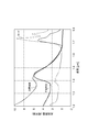
- the light source 31 in the measurement unit 30, the light source 31 generates broadband light whose spectrum continuously spread over a wavelength range of 1.6 ⁇ m to 1.8 ⁇ m (1.6 ⁇ m to 1.8 ⁇ m). .
- lipid lesions have an absorption peak at a wavelength of 1.70 to 1.75 ⁇ m (1.70 ⁇ m to 1.75 ⁇ m), which is different from normal blood vessels in this respect. Since lard, which is a pure lipid, also has a similar absorption peak, it can be said that this absorption peak is due to lipid.
- the analysis unit 36 extracts a spectral component having an absorption peak in the wavelength range of 1.70 to 1.75 ⁇ m (range of 1.70 ⁇ m to 1.75 ⁇ m) from the spectrum of the back reflected light, and this spectral component Based on the above, lipid distribution information is analyzed, and the analysis result is acquired as image information.
- the tomographic analysis of the object 3 is performed by selecting a wavelength band that is less affected by substance absorption and performing Fourier analysis of the spectrum. Structural information is obtained. By analyzing the tomographic structure information and the lipid absorption information together, it is possible to calculate a tomographic image displaying lipid distribution.
- the optical fiber 11, the condensing optical system 13, the deflecting optical system 14, the buffer fluid 17 and the jacket tube 16 are not all the same material, their refractive indexes are not necessarily equal and light can be reflected at the interface between them. . Since the reflected light generated at the interface of the optical probe 10 is detected by being mixed with the back-reflected light from the object 3, it can be a noise. However, in the present embodiment, the reflected light generated at the interface of the optical probe 10 is used for calibration of the measurement system.
- the back reflected light from the object 3 and the reference light pass through different optical paths, so that the chromatic dispersion on the optical path may be different from each other.
- the group delay time of light differs depending on the wavelength.
- a spectrum that is a function of wavelength is Fourier-analyzed to calculate an autocorrelation function as a function of group delay time, and a tomographic image is generated based on the calculated function. It is known that the spatial resolution decreases.
- the reference object such as a mirror is measured instead of the object 3 to measure the influence of chromatic dispersion, and data processing for compensating the dispersion based on the result is performed. It is known that this can be solved.
- spectral information is used not only for obtaining a tomographic image but also for estimating a material distribution, so that it is more sensitive to the influence of chromatic dispersion than conventional OCT. Therefore, in the conventional method in which the dispersion compensation process is performed before measuring the object 3, the estimation of the material distribution may be affected by the mechanical fluctuation of the measurement system that may occur during the measurement or the chromatic dispersion fluctuation due to the temperature fluctuation. . Therefore, during the measurement, the dispersion compensation process can be performed by measuring the reflection at the interface of the optical probe 10 at the distal end 11b immediately before the measurement or immediately after the measurement.
- the reflected light generated at the interface of the optical probe 10 at the distal end 11b and the reference light are caused to interfere with each other and detected by the photodetector 33, and the wavelength spectrum is detected by the analysis unit 36 in a plurality of limited wavelength bands.
- the analysis unit 36 Calculating the wavelength dependence of the delay time in the wavelength band with a peak autocorrelation function, and calculating an estimate of the chromatic dispersion received by the back-reflected light) and numerically canceling the estimated chromatic dispersion Dispersion compensation processing can be performed by adding dispersion to.
- This objective can be achieved when reflected light having an intensity that can be observed and does not saturate the photodetector 33 is generated at one interface of the optical probe 10 at the distal end 11b.
- the reflectivity is -100 to -50 dB (-100 dB or more and -50 dB or less) and 10 dB or more higher than the other interfaces. Reflection at reflectivity can occur.
- the external medium existing outside the jacket tube 16 is typically blood or physiological saline, and has a refractive index (wavelength 589 nm, which is a typical refractive index evaluation wavelength). Is the same as in the following).
- the jacket tube 16 is made of FEP or PFA (refractive index 1.34)
- the buffer fluid 17 is physiological saline (refractive index 1.33)
- the optical fiber 11 is condensing optics.
- the relative refractive index difference at the interface between the optical fiber 11 and the condensing optical system 13 is 0%
- the relative refractive index difference at the interface between the condensing optical system 13 and the deflecting optical system 14 is 0%
- the relative refractive index difference at the interface between the deflection optical system 14 and the buffer fluid 17 is 8.9%
- the relative refractive index difference at the interface between the buffer fluid 17 and the jacket tube 16 is 0.82%.
- the relative refractive index difference at the interface with the external medium is 0.82%.
- the relative refractive index difference at one of the interface between the deflection optical system 14 and the buffer fluid 17 and the interface between the buffer fluid 17 and the jacket tube 16 is 3.2 times the relative refractive index difference at the other interface. It is different.
- the refractive indexes of the medium on both sides of the interface are n1 and n2
- the relative refractive index difference at the interface is 2 (n1-n2) / (n1 + n2) Is defined by
- the relative refractive index difference of 8.9% at the interface between the deflection optical system 14 and the buffer fluid 17 is 11 times that of the other interfaces. Since the reflectance at the interface is proportional to the square of the relative refractive index difference, the reflectance at the interface between the deflection optical system 14 and the buffer fluid 17 is 21 dB or more higher than the reflectance at the other interfaces. Since the refractive indexes of the optical fiber 11, the condensing optical system 13, and the deflecting optical system 14 are the same, the reflectance at the interface between them can be ignored.
Landscapes
- Health & Medical Sciences (AREA)
- Life Sciences & Earth Sciences (AREA)
- Physics & Mathematics (AREA)
- General Health & Medical Sciences (AREA)
- Pathology (AREA)
- Engineering & Computer Science (AREA)
- Public Health (AREA)
- Biophysics (AREA)
- Biomedical Technology (AREA)
- Heart & Thoracic Surgery (AREA)
- Medical Informatics (AREA)
- Molecular Biology (AREA)
- Surgery (AREA)
- Animal Behavior & Ethology (AREA)
- Veterinary Medicine (AREA)
- General Physics & Mathematics (AREA)
- Radiology & Medical Imaging (AREA)
- Nuclear Medicine, Radiotherapy & Molecular Imaging (AREA)
- Physiology (AREA)
- Cardiology (AREA)
- Optics & Photonics (AREA)
- Spectroscopy & Molecular Physics (AREA)
- Immunology (AREA)
- Vascular Medicine (AREA)
- Biochemistry (AREA)
- Analytical Chemistry (AREA)
- Chemical & Material Sciences (AREA)
- Artificial Intelligence (AREA)
- Signal Processing (AREA)
- Psychiatry (AREA)
- Computer Vision & Pattern Recognition (AREA)
- Mathematical Physics (AREA)
- Investigating Or Analysing Materials By Optical Means (AREA)
- Endoscopes (AREA)
Priority Applications (4)
| Application Number | Priority Date | Filing Date | Title |
|---|---|---|---|
| KR1020147025459A KR20140123591A (ko) | 2012-02-15 | 2012-07-23 | 광 프로브 및 광학적 측정 방법 |
| EP12788412.0A EP2803973A4 (de) | 2012-02-15 | 2012-07-23 | Optische sonde und optisches messverfahren |
| CN201280069873.7A CN104126111A (zh) | 2012-02-15 | 2012-07-23 | 光学探针及光学测定方法 |
| US14/373,342 US20150245768A1 (en) | 2012-02-15 | 2012-07-23 | Optical probe, optical measurement method, and optical measurement device |
Applications Claiming Priority (2)
| Application Number | Priority Date | Filing Date | Title |
|---|---|---|---|
| JP2012030956A JP5120509B1 (ja) | 2012-02-15 | 2012-02-15 | 光プローブおよび光学的測定方法 |
| JP2012-030956 | 2012-02-15 |
Publications (1)
| Publication Number | Publication Date |
|---|---|
| WO2013121602A1 true WO2013121602A1 (ja) | 2013-08-22 |
Family
ID=47692827
Family Applications (1)
| Application Number | Title | Priority Date | Filing Date |
|---|---|---|---|
| PCT/JP2012/068605 WO2013121602A1 (ja) | 2012-02-15 | 2012-07-23 | 光プローブおよび光学的測定方法 |
Country Status (6)
| Country | Link |
|---|---|
| US (1) | US20150245768A1 (de) |
| EP (1) | EP2803973A4 (de) |
| JP (1) | JP5120509B1 (de) |
| KR (1) | KR20140123591A (de) |
| CN (1) | CN104126111A (de) |
| WO (1) | WO2013121602A1 (de) |
Cited By (2)
| Publication number | Priority date | Publication date | Assignee | Title |
|---|---|---|---|---|
| WO2015025932A1 (ja) * | 2013-08-23 | 2015-02-26 | 住友電気工業株式会社 | 光プローブおよび光学的測定方法 |
| EP3050483A4 (de) * | 2013-09-27 | 2017-05-17 | Terumo Kabushiki Kaisha | Bilddiagnosevorrichtung und verfahren zur steuerung davon |
Families Citing this family (7)
| Publication number | Priority date | Publication date | Assignee | Title |
|---|---|---|---|---|
| JP2015097569A (ja) * | 2013-11-18 | 2015-05-28 | 住友電気工業株式会社 | 光干渉断層撮像用光プローブ及びその製造方法 |
| WO2016168605A1 (en) * | 2015-04-16 | 2016-10-20 | Gentuity, Llc | Micro-optic probes for neurology |
| EP3344126A4 (de) | 2015-08-31 | 2019-05-08 | Gentuity LLC | Abbildungssystem mit bildgebender sonde und abgabevorrichtungen |
| WO2019108598A1 (en) | 2017-11-28 | 2019-06-06 | Gentuity, Llc | Imaging system |
| WO2019144237A1 (en) * | 2018-01-25 | 2019-08-01 | Provincial Health Services Authority | Endoscopic raman spectroscopy device |
| CN118105046A (zh) * | 2018-04-24 | 2024-05-31 | 江苏鱼跃医疗设备股份有限公司 | 一种血压计用气接头及血压计 |
| EP3841736A4 (de) * | 2018-09-17 | 2022-05-18 | Gentuity LLC | Bildgebungssystem mit optischem pfad |
Citations (7)
| Publication number | Priority date | Publication date | Assignee | Title |
|---|---|---|---|---|
| JP2000097846A (ja) * | 1998-09-21 | 2000-04-07 | Olympus Optical Co Ltd | 光走査プローブ装置 |
| US6445939B1 (en) | 1999-08-09 | 2002-09-03 | Lightlab Imaging, Llc | Ultra-small optical probes, imaging optics, and methods for using same |
| US20020151823A1 (en) | 2001-03-21 | 2002-10-17 | Naohiko Miyata | Wire-stranded hollow tube, a medical tube body and a medical guide wire |
| JP2005534428A (ja) * | 2002-08-05 | 2005-11-17 | インフラレドックス インコーポレーティッド | 血管壁の近赤外分光分析 |
| JP2007510907A (ja) * | 2003-11-06 | 2007-04-26 | フォルテバイオ,インク. | 位相シフト干渉法に基づく光ファイバー検定装置 |
| JP2007206049A (ja) * | 2006-03-13 | 2007-08-16 | Olympus Corp | 光イメージング装置 |
| JP2008514383A (ja) * | 2004-09-29 | 2008-05-08 | ザ ジェネラル ホスピタル コーポレイション | 光学コヒーレンス画像形成のためのシステム及び方法 |
Family Cites Families (6)
| Publication number | Priority date | Publication date | Assignee | Title |
|---|---|---|---|---|
| US5479546A (en) * | 1994-05-16 | 1995-12-26 | Litton Systems, Inc. | Optimized non-linear effect tapered optical fiber interferometer/switch device |
| US6763261B2 (en) * | 1995-09-20 | 2004-07-13 | Board Of Regents, The University Of Texas System | Method and apparatus for detecting vulnerable atherosclerotic plaque |
| US6615072B1 (en) * | 1999-02-04 | 2003-09-02 | Olympus Optical Co., Ltd. | Optical imaging device |
| US7460785B2 (en) * | 2001-05-23 | 2008-12-02 | Lucent Technologies Inc. | Performance monitoring in an optical communication system |
| US7486985B2 (en) * | 2002-08-05 | 2009-02-03 | Infraredx, Inc. | Near-infrared spectroscopic analysis of blood vessel walls |
| EP2124718B1 (de) * | 2007-03-20 | 2012-10-03 | Topcon Europe Medical B.V. | Vorrichtung zur betrachtung eines auges und oct-modul |
-
2012
- 2012-02-15 JP JP2012030956A patent/JP5120509B1/ja active Active
- 2012-07-23 EP EP12788412.0A patent/EP2803973A4/de not_active Withdrawn
- 2012-07-23 WO PCT/JP2012/068605 patent/WO2013121602A1/ja active Application Filing
- 2012-07-23 KR KR1020147025459A patent/KR20140123591A/ko not_active Application Discontinuation
- 2012-07-23 US US14/373,342 patent/US20150245768A1/en not_active Abandoned
- 2012-07-23 CN CN201280069873.7A patent/CN104126111A/zh active Pending
Patent Citations (7)
| Publication number | Priority date | Publication date | Assignee | Title |
|---|---|---|---|---|
| JP2000097846A (ja) * | 1998-09-21 | 2000-04-07 | Olympus Optical Co Ltd | 光走査プローブ装置 |
| US6445939B1 (en) | 1999-08-09 | 2002-09-03 | Lightlab Imaging, Llc | Ultra-small optical probes, imaging optics, and methods for using same |
| US20020151823A1 (en) | 2001-03-21 | 2002-10-17 | Naohiko Miyata | Wire-stranded hollow tube, a medical tube body and a medical guide wire |
| JP2005534428A (ja) * | 2002-08-05 | 2005-11-17 | インフラレドックス インコーポレーティッド | 血管壁の近赤外分光分析 |
| JP2007510907A (ja) * | 2003-11-06 | 2007-04-26 | フォルテバイオ,インク. | 位相シフト干渉法に基づく光ファイバー検定装置 |
| JP2008514383A (ja) * | 2004-09-29 | 2008-05-08 | ザ ジェネラル ホスピタル コーポレイション | 光学コヒーレンス画像形成のためのシステム及び方法 |
| JP2007206049A (ja) * | 2006-03-13 | 2007-08-16 | Olympus Corp | 光イメージング装置 |
Non-Patent Citations (2)
| Title |
|---|
| See also references of EP2803973A4 * |
| W. M. SUH, CIRC CARDIOVASC IMAGING., vol. 4, 2011, pages 169 - 178 |
Cited By (3)
| Publication number | Priority date | Publication date | Assignee | Title |
|---|---|---|---|---|
| WO2015025932A1 (ja) * | 2013-08-23 | 2015-02-26 | 住友電気工業株式会社 | 光プローブおよび光学的測定方法 |
| EP3050483A4 (de) * | 2013-09-27 | 2017-05-17 | Terumo Kabushiki Kaisha | Bilddiagnosevorrichtung und verfahren zur steuerung davon |
| US10470665B2 (en) | 2013-09-27 | 2019-11-12 | Terumo Kabushiki Kaisha | Imaging apparatus for diagnosis and method of controlling the same |
Also Published As
| Publication number | Publication date |
|---|---|
| KR20140123591A (ko) | 2014-10-22 |
| CN104126111A (zh) | 2014-10-29 |
| JP2013167537A (ja) | 2013-08-29 |
| EP2803973A1 (de) | 2014-11-19 |
| EP2803973A4 (de) | 2015-06-03 |
| JP5120509B1 (ja) | 2013-01-16 |
| US20150245768A1 (en) | 2015-09-03 |
Similar Documents
| Publication | Publication Date | Title |
|---|---|---|
| JP5120509B1 (ja) | 光プローブおよび光学的測定方法 | |
| JP6770109B2 (ja) | 全方向視覚装置 | |
| US8804115B2 (en) | Systems and methods for performing optical spectroscopy using a self-calibrating fiber optic probe | |
| JP5522305B1 (ja) | 光学的測定システムおよびその作動方法 | |
| JP7401527B2 (ja) | 光学形状感知及びスペクトル組織感知のための統合型ファイバ | |
| US9645322B2 (en) | Optical probe for optical coherence tomography and manufacturing method therefor | |
| JP5959652B2 (ja) | 散乱光計測装置 | |
| US20140212091A1 (en) | Optical probe | |
| WO2015025932A1 (ja) | 光プローブおよび光学的測定方法 | |
| JP5983676B2 (ja) | 光プローブ | |
| US9128249B2 (en) | Optical probe and optical measuring method | |
| JP5505553B2 (ja) | 光学的測定装置 | |
| JP5700165B2 (ja) | 光学的測定装置 | |
| JP6024151B2 (ja) | 光プローブ | |
| JP5545423B1 (ja) | 光学的測定装置 | |
| JP5708599B2 (ja) | 光プローブ | |
| JP2013088138A (ja) | 屈折率測定装置および濃度測定装置並びにその方法 | |
| CN107072558A (zh) | 成像和/或压力测量导管及其使用方法 |
Legal Events
| Date | Code | Title | Description |
|---|---|---|---|
| WWE | Wipo information: entry into national phase |
Ref document number: 2012788412 Country of ref document: EP |
|
| 121 | Ep: the epo has been informed by wipo that ep was designated in this application |
Ref document number: 12788412 Country of ref document: EP Kind code of ref document: A1 |
|
| WWE | Wipo information: entry into national phase |
Ref document number: 14373342 Country of ref document: US |
|
| NENP | Non-entry into the national phase |
Ref country code: DE |
|
| ENP | Entry into the national phase |
Ref document number: 20147025459 Country of ref document: KR Kind code of ref document: A |