WO2013118574A1 - Power supply control device - Google Patents
Power supply control device Download PDFInfo
- Publication number
- WO2013118574A1 WO2013118574A1 PCT/JP2013/051195 JP2013051195W WO2013118574A1 WO 2013118574 A1 WO2013118574 A1 WO 2013118574A1 JP 2013051195 W JP2013051195 W JP 2013051195W WO 2013118574 A1 WO2013118574 A1 WO 2013118574A1
- Authority
- WO
- WIPO (PCT)
- Prior art keywords
- power supply
- compressor
- inverter
- unit
- voltage
- Prior art date
Links
Images


Classifications
-
- H—ELECTRICITY
- H02—GENERATION; CONVERSION OR DISTRIBUTION OF ELECTRIC POWER
- H02H—EMERGENCY PROTECTIVE CIRCUIT ARRANGEMENTS
- H02H7/00—Emergency protective circuit arrangements specially adapted for specific types of electric machines or apparatus or for sectionalised protection of cable or line systems, and effecting automatic switching in the event of an undesired change from normal working conditions
- H02H7/08—Emergency protective circuit arrangements specially adapted for specific types of electric machines or apparatus or for sectionalised protection of cable or line systems, and effecting automatic switching in the event of an undesired change from normal working conditions for dynamo-electric motors
- H02H7/0833—Emergency protective circuit arrangements specially adapted for specific types of electric machines or apparatus or for sectionalised protection of cable or line systems, and effecting automatic switching in the event of an undesired change from normal working conditions for dynamo-electric motors for electric motors with control arrangements
-
- H—ELECTRICITY
- H02—GENERATION; CONVERSION OR DISTRIBUTION OF ELECTRIC POWER
- H02M—APPARATUS FOR CONVERSION BETWEEN AC AND AC, BETWEEN AC AND DC, OR BETWEEN DC AND DC, AND FOR USE WITH MAINS OR SIMILAR POWER SUPPLY SYSTEMS; CONVERSION OF DC OR AC INPUT POWER INTO SURGE OUTPUT POWER; CONTROL OR REGULATION THEREOF
- H02M1/00—Details of apparatus for conversion
- H02M1/36—Means for starting or stopping converters
-
- H—ELECTRICITY
- H02—GENERATION; CONVERSION OR DISTRIBUTION OF ELECTRIC POWER
- H02M—APPARATUS FOR CONVERSION BETWEEN AC AND AC, BETWEEN AC AND DC, OR BETWEEN DC AND DC, AND FOR USE WITH MAINS OR SIMILAR POWER SUPPLY SYSTEMS; CONVERSION OF DC OR AC INPUT POWER INTO SURGE OUTPUT POWER; CONTROL OR REGULATION THEREOF
- H02M7/00—Conversion of ac power input into dc power output; Conversion of dc power input into ac power output
- H02M7/42—Conversion of dc power input into ac power output without possibility of reversal
- H02M7/44—Conversion of dc power input into ac power output without possibility of reversal by static converters
- H02M7/48—Conversion of dc power input into ac power output without possibility of reversal by static converters using discharge tubes with control electrode or semiconductor devices with control electrode
- H02M7/53—Conversion of dc power input into ac power output without possibility of reversal by static converters using discharge tubes with control electrode or semiconductor devices with control electrode using devices of a triode or transistor type requiring continuous application of a control signal
- H02M7/537—Conversion of dc power input into ac power output without possibility of reversal by static converters using discharge tubes with control electrode or semiconductor devices with control electrode using devices of a triode or transistor type requiring continuous application of a control signal using semiconductor devices only, e.g. single switched pulse inverters
- H02M7/5387—Conversion of dc power input into ac power output without possibility of reversal by static converters using discharge tubes with control electrode or semiconductor devices with control electrode using devices of a triode or transistor type requiring continuous application of a control signal using semiconductor devices only, e.g. single switched pulse inverters in a bridge configuration
-
- Y—GENERAL TAGGING OF NEW TECHNOLOGICAL DEVELOPMENTS; GENERAL TAGGING OF CROSS-SECTIONAL TECHNOLOGIES SPANNING OVER SEVERAL SECTIONS OF THE IPC; TECHNICAL SUBJECTS COVERED BY FORMER USPC CROSS-REFERENCE ART COLLECTIONS [XRACs] AND DIGESTS
- Y10—TECHNICAL SUBJECTS COVERED BY FORMER USPC
- Y10S—TECHNICAL SUBJECTS COVERED BY FORMER USPC CROSS-REFERENCE ART COLLECTIONS [XRACs] AND DIGESTS
- Y10S388/00—Electricity: motor control systems
- Y10S388/90—Specific system operational feature
- Y10S388/903—Protective, e.g. voltage or current limit
Definitions
- the present invention relates to a power supply control device.
- a refrigeration apparatus such as an air conditioner is provided with various devices such as a compressor and a fan.
- a motor is often used as a drive source for these devices.
- the motor is driven by electric power (hereinafter simply referred to as power supply) supplied from the commercial power supply unit.
- power supply electric power supplied from the commercial power supply unit.
- the high pressure abnormality means that the pressure of the refrigerant after being compressed by the compressor deviates from the normal pressure range for some reason related to the compressor, resulting in a high pressure state higher than a predetermined value on the high pressure side of the range. The phenomenon that ends up.
- Patent Document 1 Japanese Patent No. 4738129
- a technique is known in which when a high voltage abnormality occurs, power supply to the motor is interrupted to stop the operation of the refrigeration apparatus.
- Patent Document 1 a circuit serving as a switch is provided on a line for supplying power to an inverter, and the switch is turned off when a high voltage abnormality occurs.
- the power supplied to the line is an AC voltage of about 200 V and a large amount of current, so-called strong electricity. Therefore, the switch may be welded.
- the above line is not interrupted. Therefore, if the microcomputer that controls the inverter runs out of control, a control signal will continue to be output from the computer to the inverter, and the compressor will continue to operate. .
- the subject of this invention is providing the power supply control apparatus which can stop the driving
- the power supply control device includes an inverter, an inverter control unit, a power supply unit, a detection unit, and a power supply control unit.
- the inverter has a plurality of switching elements. When the switching elements are turned on or off, the inverter generates a driving voltage for driving a compressor motor that is a driving source of the compressor, Output.
- the inverter control unit controls the inverter.
- a power supply part produces
- this power supply control device when there is an abnormality related to the compressor, the operation of generating the first power supply by the power supply unit is stopped, whereby the supply of the first power supply to the inverter control unit is cut off.
- the inverter control unit stops outputting the inverter control signal, so the drive voltage output from the inverter to the compressor motor is stopped, and the compressor operation is stopped. Stops.
- the first power supplied from the power supply unit to the inverter control unit is weaker than the power supplied to the line from the commercial power supply unit to the inverter.
- the power supply unit in the power supply control device according to the first aspect, the power supply unit generates a first power supply using an external power supply supplied from an external power supply unit located outside.
- the power supply control unit stops the generation operation of the first power supply by the power supply unit by cutting off the supply of the external power supply to the power supply unit.
- the inverter control unit first stops the drive control operation of the inverter, and as a result, for the inverter compressor The drive voltage output to the motor is stopped.
- a power supply control device is the power supply control device according to the second aspect, wherein the power supply control unit includes a relay provided on a power supply line connecting the external power supply unit and the power supply unit.
- the current flowing through the power supply line is smaller than the current flowing through the inverter.
- examples of the external power source include a commercial power source. Since the current flowing through the power line is smaller than the current flowing through the inverter, it can be said that the power line is a line for low power. Thereby, as a relay provided on a power supply line, since the thing for weak electricity can be used, cost reduction can be aimed at. Furthermore, since a large current that flows through the inverter does not flow through the relay, the risk of the relay being welded is low.
- the power supply control device is the power supply control device according to the first to third aspects, further comprising an inverter drive unit.
- the inverter drive unit turns each switching element on or off based on the output of the inverter control unit.
- the power supply unit further generates a second power supply.
- the second power source is a power source different from the first power source, and is a power source supplied to the inverter drive unit. Furthermore, in the power supply unit, when there is an abnormality related to the compressor, the generation operation of the second power supply is also stopped. In this power supply control device, the power supply unit generates the second power supply in addition to the first power supply.
- the generation operation of the second power supply is stopped in addition to the generation operation of the first power supply. To do. As a result, not only the supply of the first power source to the inverter control unit but also the supply of the second power source to the inverter drive unit is cut off. As a result, when there is an abnormality related to the compressor, the output operation of the drive voltage by the inverter is more reliably stopped.
- the operation of the compressor can be reliably stopped regardless of whether or not the switch is welded and without causing the inverter control unit to run away.
- the power supply control device according to the second aspect of the present invention, when there is an abnormality related to the compressor, the supply of external power to the power supply unit is cut off. Therefore, the inverter drive control operation is first performed by the inverter control unit. As a result, output of the drive voltage to the compressor motor of the inverter is stopped.
- the relay provided on the power supply line can be used for low power, so that the cost can be reduced. Furthermore, since a large current that flows through the inverter does not flow through the relay, the risk of the relay being welded is low.
- the output operation of the drive voltage by the inverter is more reliably stopped.
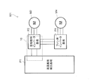
- FIG. 1 is a schematic configuration diagram of a motor drive system.
- FIG. 1 is a schematic configuration diagram of a motor drive system 101.
- the motor drive system 101 includes a plurality of motors M2, M4,..., A high voltage abnormality detection board P1 on which some components of the power supply control device 10 according to the present embodiment are mounted, and the rest of the power supply control device 10.
- the compressor inverter board P2 on which the above components are mounted and the fan inverter board P4 are configured.
- it can be a three-phase brushless DC motor.
- the motors M2, M4,... are composed of a stator composed of a plurality of drive coils, a rotor composed of permanent magnets, a hall element for detecting the position of the rotor with respect to the stator, etc. have.
- the high voltage abnormality detection board P1 is connected to each inverter board P2, P4 via a harness.
- the high voltage abnormality detection board P1 not only performs overall control of the inverter boards P2 and P4, but also detects an abnormality related to the compressor.
- examples of the abnormality related to the compressor include a high-pressure abnormality.
- the compressor inverter board P2 is a board for driving the compressor motor M2
- the fan inverter board P4 is a board for driving the fan motor M4.
- Each inverter board P2, P4 is electrically connected to the corresponding motor M2, M4 via a harness.
- substrate P2, P4 is also electrically connected through the harness.
- a plurality of compressors are provided, but FIG.
- FIG. 1 shows a case where there is one combination of the compressor motor M2 and the compressor inverter board P2 for convenience of explanation.
- a combination of a compressor motor M2 and a compressor inverter board P2 is provided for each compressor. Therefore, although omitted in FIG. 1, there are a plurality of combinations of the compressor motor M2 and the compressor inverter board P2.
- FIG. 2 is a diagram schematically showing a circuit configuration mounted on the high voltage abnormality detection board P1.
- the high-voltage abnormality detection board P ⁇ b> 1 mainly includes abnormality detection switches S ⁇ b> 11 and S ⁇ b> 12 (corresponding to a detection unit), an overall control microcomputer 13, an overall control switch S ⁇ b> 14, and an interface 15.
- the abnormality detection switches S11 and S12 are part of the components of the power supply control device 10 according to the present embodiment.
- the abnormality detection switches S11 and S12 are connected in series via sockets S11a and S12a provided on a power line L11 of about 16V.
- the abnormality detection switches S11 and S12 are provided corresponding to the number of compressors in the outdoor unit, and detect the presence or absence of abnormality in each corresponding compressor. Specifically, the pressure of the refrigerant after being compressed by the corresponding compressor is out of the normal pressure range due to some cause relating to the compressor, and is in a high pressure state higher than a predetermined value on the high pressure side of the pressure range.
- the abnormality detection switches S11 and S12 operate to change the state of the switches themselves. That is, the abnormality detection switches S11 and S12 according to the present embodiment are high-pressure switches (ie, HPS: High Pressure Switch) that detect a high-pressure abnormality.
- each abnormality detection switch S11, S12 takes an ON state when there is no abnormality in the corresponding compressor (that is, when it is normal). Conversely, each abnormality detection switch S11, S12 takes an off state when there is an abnormality in the corresponding compressor.
- a voltage lower than about 30 V here, about 16 V
- the number of the compressors of an outdoor unit is two as an example, Therefore, the case where two abnormality detection switches S11 and S12 are provided is represented. Accordingly, if there is an abnormality in at least one of the two compressors, at least one of the abnormality detection switches S11 and S12 connected in series is turned off, so that the power line L11 of about 16V in FIG. It will be blocked.
- the voltage of about 16 V applied to the power supply line L11 is generated by a switching power supply unit (not shown) that is also mounted on the high voltage abnormality detection substrate P1.
- a connection portion between the abnormality detection switch S12 and the interface 15 is referred to as a “connection point sa1”.
- the overall control microcomputer 13 comprehensively controls various devices constituting the air conditioner, such as compressors, fans, motors M2, M4,. Is. Specifically, when various signals are input from these various devices, the overall control microcomputer 13 receives motors (for example, motors M2, M4,. ..) Control the drive. More specific control contents by the overall control microcomputer 13 include, for example, the following.
- the overall control microcomputer 13 detects the value of the leakage current in the motors M2, M4,. When the detection result of at least one of the motors M2, M4,... Exceeds a predetermined value, the overall control microcomputer 13 indicates that any of the motors M2, M4,. The control which judges that it has arisen and stops applicable motor M2, M4, ... is mentioned. In order to perform the above-described control, the overall control microcomputer 13 outputs a voltage for turning on and off the overall control switch S14 to the switch S14. (2-1-3) General control switch The general control switch S14 is composed of a Pch bipolar transistor, and is connected in series between the abnormality detection switches S11, S12 and the resistor R11 located on the GND side. ing. Specifically, the emitter of the overall control switch S14 is connected to the abnormality detection switch S12 via the interface 15, the base is connected to the output of the overall control microcomputer 13, and the collector is connected to GND via the resistor R11. .
- Such an overall control switch S14 is turned on or off based on the control content of the overall control microcomputer 13. Specifically, when the overall control microcomputer 13 determines that no current abnormality or the like has occurred, the computer 13 determines a voltage of about 0 V (that is, “L”) to turn on the overall control switch S14. ) Is output, the overall control switch S14 is turned on. However, when the overall control microcomputer 13 determines that a current abnormality or the like has occurred, the computer 13 outputs about 16 V (that is, “H”) that turns off the overall control switch S14. The overall control switch S14 is in an off state.
- the high voltage abnormality detection board P1 not only the abnormality detection of the compressor by the abnormality detection switches S11 and S12 but also the detection of the leakage current in the motors M2, M4,.
- the line L11 is cut off.
- the power line L11 of about 16V is cut off due to the detection result of the leakage current, so that it can be said that the safety is increased.
- connection point sa2 a connection portion between the emitter of the overall control switch S14 and the interface 15 is referred to as a “connection point sa2”.
- the interface 15 is for electrically connecting the high-voltage abnormality detection board P1 to the inverter board P2 for the compressor, and includes tip portions of two harnesses extending from the inverter board P2. Is configured with a connector to be connected.
- Such an interface 15 is connected in series with the switches S12 and S14 between the abnormality detection switch S12 and the overall control switch S14 on the power supply line L11. Accordingly, the two harnesses extending from the compressor inverter board P2 are connected to the two connection points sa1 and sa2 via the interface 15.
- FIG. 3 is a diagram schematically showing a circuit configuration mounted on the compressor inverter board P2.
- the compressor inverter board P2 mainly includes three interfaces 21, 22, 23, a switching power supply unit 24, a power control switch S25 (corresponding to a power control unit), a rectifying unit 26, and a smoothing capacitor 27.
- the microcomputer 30 for compressors comprises the power supply control apparatus 10 which concerns on this embodiment.
- the interface 21 is for electrically connecting the high-voltage abnormality detection board P1 and the compressor inverter board P2.
- the interface 21 is formed of a connector so that the other end portions of the two harnesses, one end of which is connected to the interface 15 of the high voltage abnormality detection board P1, are connected. That is, the interface 21 is for connecting the connection point sa1 and the connection point sa2 on the high voltage abnormality detection board P1 with a circuit on the compressor inverter board P2 side.
- the interface 22 is for electrically connecting the compressor motor M2 and the compressor inverter board P2.
- the interface 23 is for electrically connecting the fan inverter board P4 and the compressor inverter board P2.
- the interfaces 22 and 23 are each formed of a connector to which three harnesses are connected.
- the interface 22 outputs drive voltages SU1, SV1, and SW1, which will be described later, to the compressor motor M2.
- a second power source V2 (to be described later) is supplied to the inverter board P4 for fans, and various voltages Vf and Vgnd are applied.
- the switching power supply unit 24 has an input side connected to a commercial power source unit (corresponding to an external power source unit) 90 outside the air conditioner, and an output side a microcomputer for a compressor. 30 and a compressor gate driver 29.
- the switching power supply unit 24 supplies the first power supply V1 supplied to the compressor microcomputer 30 and the compressor gate driver 29 using the commercial power supply V0 (corresponding to an external power supply) supplied from the commercial power supply unit 90.
- the second power supply V2 is generated.
- the first power supply V1 and the second power supply V2 are both power supplies having a DC voltage.
- the first power source V1 and the second power source V2 may be different from each other.
- the first power source V1 may be about 5V
- the second power source V2 may be about 15V.
- the commercial power supply V0 is a power supply having a voltage of about 200V for three-phase alternating current.
- FIG. 4 illustrates an example of a detailed configuration of the switching power supply unit 24.
- 4 mainly includes a rectifying unit 24a, a smoothing capacitor 24b, a first voltage-side high-frequency transformer 24c, a first voltage-side switching element 24d, a control circuit 24e, a second voltage-side high-frequency transformer 24f, and a first voltage-side high-frequency transformer 24f. It is comprised by the 2 voltage side switching element 24g.
- the commercial power supply V0 from the commercial power supply unit 90 is input to the switching power supply unit 24, the commercial power supply V0 is rectified by the rectification unit 24a and then smoothed by the smoothing capacitor 24b that is a primary-side electric field capacitor.
- Each of the switching elements 24d and 24g is repeatedly turned on and off at each frequency, so that the smoothed voltage becomes a high-frequency AC voltage in the high-frequency transformers 24c and 24f.
- the switching elements 24d and 24g are turned on and off by the control circuit 24e and repeatedly turned on and off at different frequencies.
- the high-frequency AC voltage is transmitted to the secondary side via the high-frequency transformers 24c and 24f
- the high-frequency AC voltage is rectified by the secondary-side diodes d1 and d2, and then by the secondary-side electric field capacitors c1 and c2. Smoothed to become a DC voltage.
- the DC voltage smoothed by the electric field capacitor c1 is output from the switching power supply unit 24 as the first power supply V1
- the DC voltage smoothed by the electric field capacitor c2 is output from the switching power supply unit 24 as the second power supply V2. .
- the power control switch S25 is for turning on and off the supply of the commercial power V0 from the commercial power supply 90 to the switching power supply 24.
- the power supply control switch 25 stops the power supply operation of the first power supply V1 and the second power supply V2 by the switching power supply unit 24 by turning off the switch 25 itself, and the control operation by the microcomputer 30 for the compressor. In addition, the driving operation of the compressor gate driver 29 can be stopped.
- such a power supply control switch S25 includes one relay coil S25a and one relay switch S25b.
- the relay coil S25a is connected in series to the points sa1 and sa2 via the interface 21 between the connection point sa1 and the connection point sa2 on the high-voltage abnormality detection board P1. Therefore, the relay coil S25a is connected in series to the abnormality detection switches S11 and S12 and the overall control switch S14 on the board P1 via the connection point sa1 and the connection point sa2 on the high voltage abnormality detection board P1. It becomes.
- the voltage across the relay coil S25a is equal to the voltage difference between the connection point sa1 and the connection point sa2.
- the relay switch S25b is provided on the power supply line L21 that connects the output of the commercial power supply unit 90 and the input of the switching power supply unit 24. More specifically, the line extending from the commercial power supply unit 90 side branches on the way into a line extending to the rectifying unit 26 side and a power supply line L21 extending to the switching power supply unit 24 side. The relay switch S25b is provided on a power supply line L21 extending from the branch point to the switching power supply unit 24 side. The relay switch S25b is turned on / off based on the value of the voltage across the relay coil S25a.
- the current flowing on the power supply line L21 is smaller than the current flowing on the compressor inverter 28. That is, the compressor inverter 28 includes the upper transistors Q28a, Q28c, Q28e in the inverter 28, the compressor motor M2, and the lower transistors Q28b, Q28d, Q28f in the inverter 28 in this order (see FIG. 5). ), Motor current flows.
- the motor current is about 30A, for example.
- the motor current does not flow through the power supply line L21 due to the circuit configuration, and the magnitude of the current flowing through the power supply line L21 is about 1A. Accordingly, a current lower than the motor current flows through the power supply line L21. Therefore, a relay switch S25b positioned on the power supply line L21 can be used for low power. Furthermore, since a large current such as a motor current does not flow through the relay switch S25b, the relay switch S25b is not welded.
- the operation of the power control switch S25 will be described.
- the abnormality detection switches S11 and S12 are both on, and the overall control switch S14 is on, a voltage of about 16 V is applied to the connection point sa1. Is applied, and a voltage close to about 0 V is applied to the connection point sa2. For this reason, the voltage across the relay switch S25b is maintained at about 16 V, and the relay switch S25b is turned on.
- the connection point sa1 is not applied with a voltage of about 16V and is in a high impedance state.
- the voltage across the relay coil S25a cannot maintain a predetermined voltage (specifically, about 16V), and the relay switch S25b is turned off.
- the overall control switch S14 is turned off by the overall control microcomputer 13
- a voltage close to about 0V is not applied to the connection point sa2, and a high impedance state is established. Therefore, also in this case, the voltage across the relay coil S25a cannot maintain a predetermined voltage (specifically, about 16V), and the relay switch S25b is turned off.
- the rectifier 26 is composed of six diodes 26a, 26b, 26c, 26d, 26e, and 26f.
- the diodes 26a and 26b, 26c and 26d, 26e and 26f are connected in series with each other, and these are connected in parallel with each other.
- Each connection point of the diodes 26a to 26b, 26c to 26d, and 26e to 26f connected in series is connected to a three-phase commercial power supply unit 90.
- the AC commercial power source V 0 output from the commercial power source unit 90 is rectified.
- the smoothing capacitor 27 has one end connected to the positive output terminal of the rectifier 26 and the other end connected to the negative output terminal of the rectifier 26.
- the smoothing capacitor 27 smoothes the voltage rectified by the rectifying unit 26.
- the voltage smoothed by the smoothing capacitor 27 (hereinafter referred to as the smoothed voltage Vf) has a relatively low ripple, and is applied to the compressor inverter 28 at the subsequent stage of the smoothing capacitor 27.
- the compressor inverter 28 includes a plurality of insulated gate bipolar transistors Q28a, Q28b, Q28c, Q28d, Q28e, Q28f (corresponding to switching elements; hereinafter simply referred to as transistors) and a plurality of free-wheeling diodes. D28a, D28b, D28c, D28d, D28e, D28f. Transistors Q28a and Q28b, Q28c and Q28d, Q28e and Q28f are connected in series to each other, and each diode D28a to D28f is connected in parallel to each transistor Q28a to Q28f.
- the compressor inverter 28 generates the drive voltages SU1 to SW1 for driving the compressor motor M2 by turning on and off the transistors Q28a to Q28f at a predetermined timing.
- the voltage SU1 ... SW1 is output to the compressor motor M2 via the interface 22.
- the compressor motor M2 can be rotated by the drive voltages SU1 to SW1.
- the compressor gate driver 29 includes a switching power supply unit 24, a compressor microcomputer 30, and transistors Q28a to Q28a as shown in FIG. It is connected to the gate of Q28f.
- the compressor gate driver 29 is supplied with the second power supply V2 from the switching power supply unit 24 and is driven using the power supply V2.
- the compressor gate driver 29 applies a gate voltage to each of the transistors Q28a to Q28f in the compressor inverter 28 based on an output (specifically, an instruction signal described below) from the compressor microcomputer 30. By performing the control, the transistors Q28a to Q28f are turned on and off.
- the compressor microcomputer 30 includes a CPU, a RAM, and a ROM, and is connected to the switching power supply unit 24 and the compressor gate driver 29.
- the compressor microcomputer 30 controls the compressor inverter 28 by receiving the supply of the first power supply V1 generated by the switching power supply unit 24 and controlling the drive of the compressor gate driver 29.
- the compressor microcomputer 30 is an instruction signal for driving the compressor motor M2 at a predetermined rotational speed in accordance with a motor drive command or the like from the overall control microcomputer 13 on the high-pressure abnormality detection board P1. Is output to the compressor gate driver 29.
- the compressor gate driver 29 outputs a gate voltage for turning on and off the transistors Q28a to Q28f of the compressor inverter 28 at a predetermined frequency. Further, when the compressor microcomputer 30 obtains a motor drive stop command or the like from the overall control microcomputer 13, the compressor microcomputer 30 sends an instruction signal for stopping the rotation of the compressor motor M2 to the compressor gate. Output to the driver 29. As a result, the compressor gate driver 29 outputs a gate voltage of “0 V” to the transistors Q28a to Q28f.
- FIG. 6 is a diagram schematically showing a circuit configuration mounted on the fan inverter board P4.
- the fan inverter board P4 mainly includes two interfaces 41 and 42, a switching power supply unit 43, a fan inverter 44, a fan gate driver 45, and a fan microcomputer 46.
- the interface 41 is for electrically connecting the compressor inverter board P2 and the fan inverter board P4.
- the interface 41 is formed of a connector to which three harnesses are connected.
- the second power supply V2 is supplied from the compressor inverter board P2 to the fan inverter board P4, and the smoothed voltage Vf and the ground voltage Vgnd are applied.
- the interface 42 is for electrically connecting the fan motor M4 and the fan inverter board P4.
- the interface 42 is formed of a connector to which three harnesses are connected. With this interface 42, drive voltages SU2, SV2, and SW2, which will be described later, are output to the fan motor M4.
- the switching power supply unit 43 has an input side connected to the switching power supply unit 24 on the compressor inverter board P2 via the interface 41, and an output side on the fan inverter board P4. Connected to the fan microcomputer 46.
- the switching power supply unit 43 is supplied with the second power supply V2 from the compressor inverter board P2 side via the interface 41.
- the switching power supply unit 43 uses the second power supply V2 to generate a third power supply V3 to be supplied to the fan microcomputer 30.
- the third power supply V3 is a power supply having a DC voltage, like the first and second power supplies V1 and V2.
- the third power source V3 can be about 5V, which is lower than the second power source V2, which is about 15V.
- An example of a detailed configuration of the switching power supply unit 43 includes a configuration similar to the configuration that generates the first power supply V1 in FIG. That is, since the switching power supply unit 24 of the inverter board P2 for the compressor generates two power supplies V1 and V2, the primary transformers 24c and 24f, the switching elements 24d and 24g, and the secondary power supply as shown in FIG.
- the circuit configuration (specifically, the diodes d1 and d2 and the electric field capacitors c1 and c2) are connected in parallel.
- the switching power supply unit 43 of the fan inverter board P4 generates only one power supply V3, in addition to the rectifying unit 24a and the smoothing capacitor 24b in FIG. One by one, and a configuration having a diode d1 and an electric field capacitor c1 constituting a secondary circuit.
- Fan Inverter The fan inverter 44 is connected in parallel to the downstream side of the smoothing capacitor 27 and both ends of the smoothing capacitor 27 of the inverter board P2 for the compressor via the interface 41. The voltage Vf and the ground voltage Vgnd are applied. The fan inverter 44 outputs the three-phase drive voltages SU2, SV2 and SW2 for driving the motor M4 to the fan motor M4 via the interface 42. As a result, the fan motor M4 can rotate.
- the configuration of the fan inverter 44 is the same as the circuit configuration of the compressor inverter 28 shown in FIG. (2-3-4) Fan Gate Driver
- the fan gate driver 45 is connected to the switching power supply unit 24 on the compressor inverter board P2 via the interface 41 as shown in FIG. Further, the fan gate driver 45 is connected to the fan microcomputer 46 and the fan inverter 44 (more specifically, the gate of each transistor in the fan inverter 44).
- the fan gate driver 45 is supplied with the second power supply V2 from the switching power supply unit 24 and is driven using the power supply V2.
- the fan gate driver 45 controls the application of the gate voltage to each transistor in the fan inverter 44 on the basis of the instruction signal that is output from the fan microcomputer 46, whereby the drive voltage SU2 is applied to the fan inverter 44. , SV2 and SW2 are generated and output.
- (2-3-5) Fan Microcomputer The fan microcomputer 46 includes a CPU, a RAM, and a ROM, and is connected to the switching power supply unit 43 and the fan gate driver 45.
- the fan microcomputer 46 controls the fan inverter 44 by receiving the supply of the third power supply V3 generated by the switching power supply unit 43 and controlling the driving of the fan gate driver 45.
- the fan microcomputer 46 generates an instruction signal for driving the fan motor M4 at a predetermined rotational speed in accordance with a motor drive command or the like from the overall control microcomputer 13 on the high-voltage abnormality detection board P1. Output to the fan gate driver 45. As a result, the fan gate driver 45 outputs a gate voltage that turns on and off each transistor of the fan inverter 44 at a predetermined frequency. In addition, when the fan microcomputer 46 receives a motor drive stop command or the like from the overall control microcomputer 13, the fan microcomputer 46 sends an instruction signal for stopping the rotation of the fan motor M 4 to the fan gate driver 45. Output to.
- the fan gate driver 45 outputs a gate voltage of “0 V” to each transistor of the fan inverter 44.
- the power supply control switch S25 is turned off due to an abnormality related to the compressor or the occurrence of a leakage current in at least one of the motors M2, M4,...
- the commercial power supply V0 is supplied to the switching power supply unit 24. Therefore, the generation operation of the second power supply V2 by the switching power supply unit 24 is stopped. For this reason, the supply of the second power supply V2 to the switching power supply unit 43 is also cut off, and the supply of the third power supply V3 to the fan microcomputer 46 is also cut off. Therefore, in this case, the fan microcomputer 46 does not control the fan inverter 44, and the fan motor M4 stops rotating.
- FIG. 7 is a flowchart showing the flow of operations in the power supply control device 10 and the motors M2, M4,.
- the compressor is operating normally and any motor M2, M4,. That is, the switches S11, S12, S14 on the high voltage abnormality detection board P1 and the power control switch S25 on the compressor inverter board P2 are all turned on, and the motors M2, M4,. Assume that driving is performed based on SU1 to SW1, SU2 to SW2,.
- Steps sp1 to sp4 When an abnormality occurs in the compressor and at least one of the abnormality detection switches S11 and S12 related to the high pressure abnormality detection board P1 changes from on to off (Yes in sp1 and Yes in sp2), the connection point sa1 changes from about 16V to a high impedance state.
- the overall control switch S14 related to the high voltage abnormality detection board P1 changes from on to off (Yes in sp3) due to leakage current occurring in at least one motor M2, M4,...
- the connection point sa2 Changes from about 0V to a high impedance state.
- the voltage across the relay coil S25a of the power control switch S25 related to the compressor inverter board P2 changes from the state of about 16 V, and the relay switch S25b changes from on to off (sp4).
- Steps sp5 to sp7 Since the relay switch S25b is off, the supply of the commercial power source V0 from the commercial power source unit 90 to the switching power source unit 24 in the compressor inverter board P2 is cut off. Therefore, the switching power supply unit 24 stops the generation operation and the output operation of the first power supply V1 and the second power supply V2 (sp5). As a result, the compressor microcomputer 30 operating using the first power supply V1 stops the control operation of the compressor gate driver 29, and the compressor gate operating using the second power supply V2. The driver 29 also stops the drive operation of the compressor inverter 28 (sp6).
- Steps sp8 to sp10 On the other hand, in step sp5, the switching power supply unit 24 stops generating and outputting the second power supply V2, so that the second power supply V2 to the switching power supply unit 43 on the fan inverter board P4 side is changed. Supply stops. Thereby, the switching power supply unit 43 stops the generation operation and the output operation of the third power supply V3 (sp8).
- the fan microcomputer 46 that has been operated using the third power supply V3 stops the control operation of the fan gate driver 45.
- the fan gate driver 45 since the supply of the second power source V2 to the fan gate driver 45 is also cut off at step sp5, the fan gate driver 45 also stops the driving operation of the fan inverter 44 (sp9). Accordingly, the output of the drive voltages SU2 to SW2 to the fan motor M4 is stopped, and the fan motor M4 stops rotating, so that the fan operation is also stopped (sp10).
- the switching power supply unit 24 on the compressor inverter board P2 stops the generation operation of the first power supply V1, and therefore the switching power supply unit 24. From the first power supply V1 to the compressor microcomputer 30 is cut off. When the first power source V1 is not supplied to the compressor microcomputer 30, the compressor microcomputer 30 does not output a control signal for the compressor inverter 28, so that the compressor inverter 28 supplies the compressor. The output of the drive voltages SU1 to SW1 to the motor M2 is stopped, and the operation of the compressor is stopped.
- the first power supply V1 is weaker than the power supplied to the line L23 from the commercial power supply unit 90 to the compressor inverter 28. Therefore, if a main circuit switch for cutting off the power supply from the commercial power supply unit 90 to the inverter 28 is provided on the line between the commercial power supply unit 90 and the rectifying unit 26, the switch is welded.
- the compressor microcomputer 30 to which the supply of the first power source V1 is stopped stops the drive control operation itself, so that the drive of the compressor motor M2 stops. Therefore, the operation of the compressor can be reliably stopped regardless of whether the main circuit switch is welded or without the runaway of the compressor microcomputer 30.
- the supply of the commercial power supply V0 from the commercial power supply unit 90 to the switching power supply unit 24 is cut off by the power supply control switch S25.
- the first power supply V1 is not supplied to the compressor microcomputer 30.
- the drive control operation of the compressor inverter 28 by the compressor microcomputer 30 is not performed first, and as a result, the output of the drive voltages SU1 to SW1 to the compressor motor M2 of the compressor inverter 28 is stopped. Is done.
- the power supply control switch S25 includes a switch relay S25b provided on the power supply line L21 that connects the commercial power supply unit 90 and the switching power supply unit 24.
- the electric current which flows through the power supply line L21 is smaller than the electric current which flows into the inverter 28 for compressors. That is, it can be said that the power supply line L21 is a line for weak electricity.
- the relay switch S25b provided on the power supply line L21 can be used for low power, so that the cost can be reduced. Furthermore, since a large current that flows to the compressor inverter 28 does not flow through the relay switch S25b, the risk of the relay switch S25b being welded is low.
- the switching power supply unit 24 when there is an abnormality related to the compressor, the switching power supply unit 24 itself stops driving, so in addition to the generation operation of the first power supply V1, the second power supply V2 The generation operation is also stopped. As a result, not only the supply of the first power supply V1 to the compressor microcomputer 30 but also the supply of the second power supply V2 to the compressor gate driver 29 is cut off. As a result, when there is an abnormality related to the compressor, the output operation of the drive voltages SU1 to SW1 by the compressor inverter 28 is more reliably stopped. (5) Modifications Although the embodiment of the present invention has been described with reference to the drawings, the specific configuration is not limited to the above-described embodiment, and can be changed without departing from the gist of the invention.
- a power supply control switch S25 ′ is provided on the primary circuit for generating the first power supply V1 in the switching power supply unit 24 ′.
- the switch S25 ′ is, for example, on the high voltage abnormality detection substrate P1 side. It is turned on and off in conjunction with the abnormality detection switches S11 and S12 and the overall control switch S14.
- the power supply control switch S25 ′ is provided in the switching power supply unit 24 ′, and therefore, on the power supply line L21 of the compressor inverter board P2 shown in FIG. Is not provided.
- the power supply control switch S25 ′ is turned on if the abnormality detection switches S11 and S12 and the overall control switch S14 are all on, and the abnormality detection switches S11 and S12 and If at least one of the control switches S14 is off, it is off. Therefore, when at least one of the abnormality relating to the compressor and the leakage current in the motors M2, M4,... Occurs, at least one of the corresponding abnormality detection switches S11 and S12 and the overall control switch S14 is turned off.
- the power control switch S25 ′ is also turned off. Therefore, the switching power supply unit 24 ′ stops the generation operation and the output operation of the first power supply V1. Accordingly, the driving of the compressor microcomputer 30 is stopped, the rotation of the compressor motor M2 is stopped, and the operation of the compressor is stopped.
- the switching power supply unit 24 ′ continuously performs the generation operation and the output operation of the second power supply V2 even when the power supply control switch S25 ′ is turned off. That is, the switching power supply unit 24 ′ has the first power supply V1 supplied to the compressor microcomputer 30 when at least one of an abnormality relating to the compressor and a leakage current in the motors M2, M4,. Only the generation operation and output operation are stopped. Therefore, in the switching power supply unit 24 ′ according to the configuration of FIG. 8, it is possible to perform an operation that moves only the fan even when the compressor is stopped. Can do.
- the overall control microcomputer 13 detects the leakage current of the motors M2, M4,.
- the overall control microcomputer 13 may further detect an abnormal rotation of the outdoor fan, a thermal abnormality of the entire indoor unit due to the ignition of the outdoor unit, or the like as an abnormality related to the outdoor unit.
- the overall control microcomputer 13 detects even one of these abnormalities, the overall control switch S14 is turned off, so that the power generation operation and the output operation by the switching power supply unit 24 are stopped. As a result, the compressor is driven. Stops.
Landscapes
- Engineering & Computer Science (AREA)
- Power Engineering (AREA)
- Control Of Multiple Motors (AREA)
- Inverter Devices (AREA)
- Control Of Ac Motors In General (AREA)
- Control Of Electric Motors In General (AREA)
- Control Of Positive-Displacement Pumps (AREA)
Abstract
Description
ところで、圧縮機においては、例えば高圧異常が生じる場合がある。高圧異常とは、圧縮機によって圧縮された後の冷媒の圧力が、該圧縮機に関する何らかの原因によって正常な圧力範囲を外れてしまい、該範囲の高圧側の所定値よりも高い高圧状態となってしまう現象を言う。
これに対し、特許文献1(特許第4738129号)に示すように、高圧異常が生じた場合、モータへの電源供給を遮断して冷凍装置の運転を停止させる技術が知られている。 A refrigeration apparatus such as an air conditioner is provided with various devices such as a compressor and a fan. A motor is often used as a drive source for these devices. The motor is driven by electric power (hereinafter simply referred to as power supply) supplied from the commercial power supply unit.
By the way, in a compressor, for example, a high pressure abnormality may occur. The high pressure abnormality means that the pressure of the refrigerant after being compressed by the compressor deviates from the normal pressure range for some reason related to the compressor, resulting in a high pressure state higher than a predetermined value on the high pressure side of the range. The phenomenon that ends up.
On the other hand, as shown in Patent Document 1 (Japanese Patent No. 4738129), a technique is known in which when a high voltage abnormality occurs, power supply to the motor is interrupted to stop the operation of the refrigeration apparatus.
そこで、本発明の課題は、圧縮機に異常が生じた場合、確実に圧縮機の運転を停止することができる電源制御装置を提供することにある。 In
Then, the subject of this invention is providing the power supply control apparatus which can stop the driving | operation of a compressor reliably, when abnormality arises in a compressor.
特に、電源部からインバータ制御部に供給される第1電源は、商用電源部からインバータへのラインに供給される電源に比して弱電である。そのため、仮に商用電源部とインバータとを繋ぐライン上にスイッチが設けられており、このスイッチが溶着したとしても、第1電源の供給が断たれたインバータ制御部は駆動制御動作自体を停止するため、圧縮機用モータの駆動が停止する。従って、スイッチの溶着の有無に関係なく、またインバータ制御部の暴走が生じることもなく、確実に圧縮機の運転を停止することができる。 In this power supply control device, when there is an abnormality related to the compressor, the operation of generating the first power supply by the power supply unit is stopped, whereby the supply of the first power supply to the inverter control unit is cut off. When the first power source is not supplied to the inverter control unit, the inverter control unit stops outputting the inverter control signal, so the drive voltage output from the inverter to the compressor motor is stopped, and the compressor operation is stopped. Stops.
In particular, the first power supplied from the power supply unit to the inverter control unit is weaker than the power supplied to the line from the commercial power supply unit to the inverter. For this reason, a switch is provided on the line connecting the commercial power supply unit and the inverter, and even if this switch is welded, the inverter control unit in which the supply of the first power supply is cut off stops the drive control operation itself. Then, the drive of the compressor motor stops. Therefore, the operation of the compressor can be surely stopped regardless of whether or not the switch is welded and without causing the inverter control unit to run away.
これにより、圧縮機に関する異常がある場合には、電源部への外部電源の供給が断たれるため、まずはインバータ制御部によるインバータの駆動制御動作が行われなくなり、その結果、インバータの圧縮機用モータへの駆動電圧の出力が停止されるようになる。 In the power supply control device according to the second aspect of the present invention, in the power supply control device according to the first aspect, the power supply unit generates a first power supply using an external power supply supplied from an external power supply unit located outside. When there is an abnormality related to the compressor, the power supply control unit stops the generation operation of the first power supply by the power supply unit by cutting off the supply of the external power supply to the power supply unit.
As a result, when there is an abnormality related to the compressor, the supply of external power to the power supply unit is cut off, so the inverter control unit first stops the drive control operation of the inverter, and as a result, for the inverter compressor The drive voltage output to the motor is stopped.
ここで、外部電源としては、例えば商用電源が挙げられる。電源ラインを流れる電流がインバータに流れる電流よりも小さいことから、電源ラインは、弱電用のラインであると言える。これにより、電源ライン上に設けられるリレーとしては、弱電用のものを用いることができるため、コストダウンを図ることができる。更に、リレーには、インバータに流れるような大きな電流は流れないため、リレーが溶着される危険性も低い。 A power supply control device according to a third aspect of the present invention is the power supply control device according to the second aspect, wherein the power supply control unit includes a relay provided on a power supply line connecting the external power supply unit and the power supply unit. The current flowing through the power supply line is smaller than the current flowing through the inverter.
Here, examples of the external power source include a commercial power source. Since the current flowing through the power line is smaller than the current flowing through the inverter, it can be said that the power line is a line for low power. Thereby, as a relay provided on a power supply line, since the thing for weak electricity can be used, cost reduction can be aimed at. Furthermore, since a large current that flows through the inverter does not flow through the relay, the risk of the relay being welded is low.
この電源制御装置では、電源部が第1電源に加えて第2電源を生成するため、圧縮機に関する異常がある場合には、第1電源の生成動作に加えて第2電源の生成動作も停止する。その結果、インバータ制御部への第1電源の供給のみならず、インバータ駆動部への第2電源の供給も断たれる。これにより、圧縮機に関する異常がある場合、インバータによる駆動電圧の出力動作が、より確実に停止することとなる。 The power supply control device according to the fourth aspect of the present invention is the power supply control device according to the first to third aspects, further comprising an inverter drive unit. The inverter drive unit turns each switching element on or off based on the output of the inverter control unit. The power supply unit further generates a second power supply. The second power source is a power source different from the first power source, and is a power source supplied to the inverter drive unit. Furthermore, in the power supply unit, when there is an abnormality related to the compressor, the generation operation of the second power supply is also stopped.
In this power supply control device, the power supply unit generates the second power supply in addition to the first power supply. Therefore, when there is an abnormality related to the compressor, the generation operation of the second power supply is stopped in addition to the generation operation of the first power supply. To do. As a result, not only the supply of the first power source to the inverter control unit but also the supply of the second power source to the inverter drive unit is cut off. As a result, when there is an abnormality related to the compressor, the output operation of the drive voltage by the inverter is more reliably stopped.
本発明の第2観点に係る電源制御装置によると、圧縮機に関する異常がある場合には、電源部への外部電源の供給が断たれるため、まずはインバータ制御部によるインバータの駆動制御動作が行われなくなり、その結果、インバータの圧縮機用モータへの駆動電圧の出力が停止されるようになる。
本発明の第3観点に係る電源制御装置によると、電源ライン上に設けられるリレーとしては、弱電用のものを用いることができるため、コストダウンを図ることができる。更に、リレーには、インバータに流れるような大きな電流は流れないため、リレーが溶着される危険性も低い。 According to the power supply control device according to the first aspect of the present invention, the operation of the compressor can be reliably stopped regardless of whether or not the switch is welded and without causing the inverter control unit to run away.
According to the power supply control device according to the second aspect of the present invention, when there is an abnormality related to the compressor, the supply of external power to the power supply unit is cut off. Therefore, the inverter drive control operation is first performed by the inverter control unit. As a result, output of the drive voltage to the compressor motor of the inverter is stopped.
According to the power supply control device according to the third aspect of the present invention, the relay provided on the power supply line can be used for low power, so that the cost can be reduced. Furthermore, since a large current that flows through the inverter does not flow through the relay, the risk of the relay being welded is low.
(1)全体構成
図1は、モータ駆動システム101の構成概略図である。モータ駆動システム101は、複数のモータM2,M4,・・・と、本実施形態に係る電源制御装置10の一部の構成要素が実装された高圧異常検出基板P1と、電源制御装置10の残りの構成要素が実装された圧縮機用インバータ基板P2と、ファン用インバータ基板P4とで構成される。
モータM2,M4,・・・は、それぞれ冷凍装置の一例である空気調和装置の室外機に備えられた圧縮機の駆動源、及び、同じく室外機に備えられたファンの駆動源であって、例えば3相のブラシレスDCモータであることができる。図示はしていないが、モータM2,M4,・・・は、複数の駆動コイルで構成されるステータ、永久磁石で構成されるロータ、及び、ステータに対するロータの位置を検出するためのホール素子等を有している。 Hereinafter, a power supply control device according to the present invention will be described in detail with reference to the drawings. The following embodiments are specific examples of the present invention and do not limit the technical scope of the present invention.
(1) Overall Configuration FIG. 1 is a schematic configuration diagram of a
Each of the motors M2, M4,... Is a compressor drive source provided in an outdoor unit of an air conditioner that is an example of a refrigeration device, and a fan drive source that is also provided in the outdoor unit, For example, it can be a three-phase brushless DC motor. Although not shown, the motors M2, M4,... Are composed of a stator composed of a plurality of drive coils, a rotor composed of permanent magnets, a hall element for detecting the position of the rotor with respect to the stator, etc. have.
圧縮機用インバータ基板P2は、圧縮機用モータM2を駆動するための基板であって、ファン用インバータ基板P4は、ファン用モータM4を駆動するための基板である。各インバータ基板P2,P4は、対応するモータM2,M4それぞれとハーネスを介して電気的に接続されている。また、各インバータ基板P2,P4同士も、ハーネスを介して電気的に接続されている。
なお、本実施形態では、圧縮機が複数備えられているが、図1では、説明の便宜上、圧縮機用モータM2及び圧縮機用インバータ基板P2の組み合わせが1つである場合を表している。しかし、実際には、圧縮機が複数ある場合は、各圧縮機ごとに、圧縮機用モータM2及び圧縮機用インバータ基板P2の組み合わせが設けられる。そのため、図1では省略しているが、圧縮機用モータM2及び圧縮機用インバータ基板P2の組み合わせは、複数存在する。 The high voltage abnormality detection board P1 is connected to each inverter board P2, P4 via a harness. The high voltage abnormality detection board P1 not only performs overall control of the inverter boards P2 and P4, but also detects an abnormality related to the compressor. Here, examples of the abnormality related to the compressor include a high-pressure abnormality.
The compressor inverter board P2 is a board for driving the compressor motor M2, and the fan inverter board P4 is a board for driving the fan motor M4. Each inverter board P2, P4 is electrically connected to the corresponding motor M2, M4 via a harness. Moreover, each inverter board | substrate P2, P4 is also electrically connected through the harness.
In the present embodiment, a plurality of compressors are provided, but FIG. 1 shows a case where there is one combination of the compressor motor M2 and the compressor inverter board P2 for convenience of explanation. However, in reality, when there are a plurality of compressors, a combination of a compressor motor M2 and a compressor inverter board P2 is provided for each compressor. Therefore, although omitted in FIG. 1, there are a plurality of combinations of the compressor motor M2 and the compressor inverter board P2.
以下では、各基板に実装されている回路構成について詳述する。
(2-1)高圧異常検出基板
図2は、高圧異常検出基板P1に実装されている回路構成を概略的に示した図である。図2に示すように、高圧異常検出基板P1は、主として、異常検知スイッチS11,S12(検知部に相当)、統括制御用マイクロコンピュータ13、統括制御用スイッチS14、及びインターフェース15を備える。異常検知スイッチS11,S12は、本実施形態に係る電源制御装置10の構成要素の一部である。
(2-1-1)異常検知スイッチ
異常検知スイッチS11,S12は、約16Vの電源ラインL11上に設けられたソケットS11a,S12aを介して、直列に接続されている。異常検知スイッチS11,S12は、室外機の圧縮機の数に対応して設けられており、対応する各圧縮機の異常の有無を検知する。具体的に、対応する圧縮機によって圧縮された後の冷媒の圧力が、該圧縮機に関する何らかの原因によって正常な圧力範囲を外れてしまい、該圧力範囲の高圧側の所定値よりも高い高圧状態となってしまった場合、異常検知スイッチS11,S12は動作して該スイッチ自身の状態が変化する。つまり、本実施形態に係る異常検知スイッチS11,S12は、高圧異常を検知する高圧圧力スイッチ(即ち、HPS:High Pressure Switch)である。 (2) Detailed Configuration Hereinafter, a circuit configuration mounted on each substrate will be described in detail.
(2-1) High Voltage Abnormality Detection Board FIG. 2 is a diagram schematically showing a circuit configuration mounted on the high voltage abnormality detection board P1. As shown in FIG. 2, the high-voltage abnormality detection board P <b> 1 mainly includes abnormality detection switches S <b> 11 and S <b> 12 (corresponding to a detection unit), an
(2-1-1) Abnormality detection switch The abnormality detection switches S11 and S12 are connected in series via sockets S11a and S12a provided on a power line L11 of about 16V. The abnormality detection switches S11 and S12 are provided corresponding to the number of compressors in the outdoor unit, and detect the presence or absence of abnormality in each corresponding compressor. Specifically, the pressure of the refrigerant after being compressed by the corresponding compressor is out of the normal pressure range due to some cause relating to the compressor, and is in a high pressure state higher than a predetermined value on the high pressure side of the pressure range. In this case, the abnormality detection switches S11 and S12 operate to change the state of the switches themselves. That is, the abnormality detection switches S11 and S12 according to the present embodiment are high-pressure switches (ie, HPS: High Pressure Switch) that detect a high-pressure abnormality.
また、本実施形態に係る図2では、一例として、室外機の圧縮機の数が2つであり、従って異常検知スイッチS11、S12も2つ設けられている場合を表している。従って、2つの圧縮機のうち、少なくとも1つの圧縮機において異常があれば、直列接続された異常検知スイッチS11,S12の少なくとも1つがオフ状態となるため、図2の約16Vの電源ラインL11は遮断されることとなる。 Here, in this embodiment, normally closed contacts are employed as the abnormality detection switches S11 and S12. That is, each abnormality detection switch S11, S12 takes an ON state when there is no abnormality in the corresponding compressor (that is, when it is normal). Conversely, each abnormality detection switch S11, S12 takes an off state when there is an abnormality in the corresponding compressor. In particular, a voltage lower than about 30 V (here, about 16 V) is applied to the abnormality detection switches S11 and S12 in the present embodiment as a weak electric voltage.
Moreover, in FIG. 2 which concerns on this embodiment, the number of the compressors of an outdoor unit is two as an example, Therefore, the case where two abnormality detection switches S11 and S12 are provided is represented. Accordingly, if there is an abnormality in at least one of the two compressors, at least one of the abnormality detection switches S11 and S12 connected in series is turned off, so that the power line L11 of about 16V in FIG. It will be blocked.
以下では、説明の便宜上、異常検知スイッチS12とインターフェース15との接続部分を“接続ポイントsa1”と言う。
(2-1-2)統括制御用マイクロコンピュータ
統括制御用マイクロコンピュータ13は、圧縮機やファン、モータM2,M4,・・・等の、空気調和装置を構成する各種機器を統括的に制御するものである。具体的には、統括制御用マイクロコンピュータ13は、これらの各種機器から様々な信号が入力されると、該信号に基づいて、各種機器の駆動原となるモータ(例えば、モータM2,M4,・・・)の駆動を制御する。統括制御用マイクロコンピュータ13によるより具体的な制御内容としては、たとえば以下が挙げられる。 The voltage of about 16 V applied to the power supply line L11 is generated by a switching power supply unit (not shown) that is also mounted on the high voltage abnormality detection substrate P1.
Hereinafter, for convenience of explanation, a connection portion between the abnormality detection switch S12 and the
(2-1-2) Overall Control Microcomputer The
上述した制御を行うため、統括制御用マイクロコンピュータ13は、統括制御用スイッチS14をオン及びオフさせるための電圧を、該スイッチS14に対して出力する。
(2-1-3)統括制御用スイッチ
統括制御用スイッチS14は、Pchのバイポーラトランジスタで構成されており、異常検知スイッチS11,S12とGND側に位置する抵抗R11との間に直列に接続されている。具体的に、統括制御用スイッチS14のエミッタはインターフェース15を介して異常検知スイッチS12に、ベースは統括制御用マイクロコンピュータ13の出力に、コレクタは抵抗R11を介してGNDに、それぞれ接続されている。 The
In order to perform the above-described control, the
(2-1-3) General control switch The general control switch S14 is composed of a Pch bipolar transistor, and is connected in series between the abnormality detection switches S11, S12 and the resistor R11 located on the GND side. ing. Specifically, the emitter of the overall control switch S14 is connected to the abnormality detection switch S12 via the
従って、高圧異常検知基板P1においては、異常検知スイッチS11,S12による圧縮機の異常検知のみならず、例えばモータM2,M4,・・・における漏洩電流の検知によっても、図2の約16Vの電源ラインL11が遮断されることとなる。特に、異常検知スイッチS11,S12が故障しており異常検知ができない状態にあっても、漏洩電流の検知結果によって約16Vの電源ラインL11が遮断されるため、安全性が増していると言える。 Such an overall control switch S14 is turned on or off based on the control content of the
Accordingly, in the high voltage abnormality detection board P1, not only the abnormality detection of the compressor by the abnormality detection switches S11 and S12 but also the detection of the leakage current in the motors M2, M4,. The line L11 is cut off. In particular, even when the abnormality detection switches S11 and S12 are out of order and the abnormality cannot be detected, the power line L11 of about 16V is cut off due to the detection result of the leakage current, so that it can be said that the safety is increased.
(2-1-4)インターフェース
インターフェース15は、高圧異常検知基板P1を圧縮機用インバータ基板P2と電気的に接続するためのものであって、該インバータ基板P2から延びる2本のハーネスの先端部分が接続されるコネクタで構成されている。
このようなインターフェース15は、電源ラインL11上において、異常検知スイッチS12と統括制御用スイッチS14との間に、該スイッチS12,S14に対して直列に接続されている。従って、圧縮機用インバータ基板P2から延びる2本のハーネスは、インターフェース15を介して2つの接続ポイントsa1,sa2と接続される。 Hereinafter, for convenience of explanation, a connection portion between the emitter of the overall control switch S14 and the
(2-1-4) Interface The
Such an
図3は、圧縮機用インバータ基板P2に実装されている回路構成を概略的に示した図である。圧縮機用インバータ基板P2は、図3に示すように、主として、3つのインターフェース21,22,23、スイッチング電源部24、電源制御スイッチS25(電源制御部に相当)、整流部26、平滑コンデンサ27、圧縮機用インバータ28、圧縮機用ゲートドライバ29(インバータ駆動部に相当)、及び、圧縮機用マイクロコンピュータ30(インバータ制御部に相当)を備える。
なお、既に述べた高圧異常検出基板P1上の異常検知スイッチS11,S12、並びに、圧縮機用インバータ基板P2におけるスイッチング電源部24、電源制御スイッチ25、圧縮機用インバータ28、圧縮機用ゲートドライバ29及び圧縮機用マイクロコンピュータ30によって、本実施形態に係る電源制御装置10が構成されている。 (2-2) Compressor Inverter Board FIG. 3 is a diagram schematically showing a circuit configuration mounted on the compressor inverter board P2. As shown in FIG. 3, the compressor inverter board P2 mainly includes three
The abnormality detection switches S11 and S12 on the high-voltage abnormality detection board P1 and the switching
インターフェース21は、高圧異常検出基板P1と圧縮機用インバータ基板P2とを電気的に接続するためのものである。インターフェース21は、一端が高圧異常検出基板P1のインターフェース15に接続された2本のハーネスの他端部分が接続されるように、コネクタで形成されている。即ち、インターフェース21は、高圧異常検出基板P1上の接続ポイントsa1及び接続ポイントsa2を、圧縮機用インバータ基板P2側の回路と繋ぐためのものである。
インターフェース22は、圧縮機用モータM2と圧縮機用インバータ基板P2とを電気的に接続するためのものである。インターフェース23は、ファン用インバータ基板P4と圧縮機用インバータ基板P2とを電気的に接続するためのものである。インターフェース22,23は、それぞれ3本のハーネスが接続されるようなコネクタで形成されている。インターフェース22により、圧縮機用モータM2へは、後述する駆動電圧SU1,SV1,SW1が出力されるようになる。インターフェース23により、ファン用インバータ基板P4へは、後述する第2電源V2が供給されると共に各種電圧Vf,Vgndが印加されるようになる。 (2-2-1) Interface The
The
スイッチング電源部24は、その入力側が空気調和装置の外部にある商用電源部(外部電源部に相当)90と接続されており、出力側が圧縮機用マイクロコンピュータ30及び圧縮機用ゲートドライバ29と接続されている。スイッチング電源部24は、商用電源部90から供給される商用電源V0(外部電源に相当)を用いて、圧縮機用マイクロコンピュータ30に供給する第1電源V1と、圧縮機用ゲートドライバ29に供給する第2電源V2とを生成する。
ここで、第1電源V1及び第2電源V2は、いずれも直流の電圧を有する電源である。第1電源V1及び第2電源V2は、互いに別々の電源であって、例えば第1電源V1は約5V、第2電源V2は、約15Vであることができる。商用電源V0は、3相交流の約200Vの電圧を有する電源である。 (2-2-2) Switching Power Supply Unit The switching
Here, the first power supply V1 and the second power supply V2 are both power supplies having a DC voltage. The first power source V1 and the second power source V2 may be different from each other. For example, the first power source V1 may be about 5V, and the second power source V2 may be about 15V. The commercial power supply V0 is a power supply having a voltage of about 200V for three-phase alternating current.
スイッチング電源部24に商用電源部90からの商用電源V0が入力されると、商用電源V0は、整流部24aにおいて整流され、次いで1次側の電界コンデンサである平滑コンデンサ24bによって平滑される。各スイッチング素子24d,24gがそれぞれ個々の周波数にてオン及びオフを繰り返すことで、平滑された電圧は、各高周波トランス24c,24fにて高周波の交流電圧となる。なお、各スイッチング素子24d,24gのオン及びオフは、制御回路24eによって制御され、互いに異なる周波数でオン及びオフを繰り返す。 FIG. 4 illustrates an example of a detailed configuration of the switching
When the commercial power supply V0 from the commercial
(2-2-3)電源制御スイッチ
電源制御スイッチS25は、商用電源部90からスイッチング電源部24への商用電源V0の供給をオン及びオフさせるためのものである。つまり、電源制御スイッチ25は、該スイッチ25自身がオフとなることで、スイッチング電源部24による第1電源V1及び第2電源V2の電源動作を停止させて、圧縮機用マイクロコンピュータ30による制御動作及び圧縮機用ゲートドライバ29の駆動動作を停止させることができる。 When the high-frequency AC voltage is transmitted to the secondary side via the high-
(2-2-3) Power Control Switch The power control switch S25 is for turning on and off the supply of the commercial power V0 from the
リレーコイルS25aは、インターフェース21を介して、高圧異常検出基板P1上の接続ポイントsa1と接続ポイントsa2との間に、該ポイントsa1,sa2に直列に接続されている。従って、リレーコイルS25aは、高圧異常検出基板P1上の接続ポイントsa1と接続ポイントsa2とを介して、該基板P1上の異常検出スイッチS11,S12及び統括制御用スイッチS14に直列に接続されることとなる。リレーコイルS25aの両端電圧は、接続ポイントsa1と接続ポイントsa2との電圧差に等しい。
リレースイッチS25bは、商用電源部90の出力とスイッチング電源部24の入力とを繋ぐ電源ラインL21上に設けられている。より具体的には、商用電源部90側から延びるラインは、途中で、整流部26側へと延びるラインと、スイッチング電源部24側へと延びる電源ラインL21とに、分岐している。リレースイッチS25bは、当該分岐点からスイッチング電源部24側へと延びる電源ラインL21上に設けられている。リレースイッチS25bは、リレーコイルS25aの両端電圧の値に基づきオン/オフする。 As shown in FIG. 3, such a power supply control switch S25 includes one relay coil S25a and one relay switch S25b.
The relay coil S25a is connected in series to the points sa1 and sa2 via the
The relay switch S25b is provided on the power supply line L21 that connects the output of the commercial
整流部26は、6つのダイオード26a,26b,26c,26d,26e,26fで構成されている。ダイオード26a及び26b、26c及び26d,26e及び26fは、それぞれ互いに直列に接続されると共に、これらは互いに並列となるように接続されている。直列接続されたダイオード26a~26b,26c~26d,26e~26fの各接続点は、3相の商用電源部90に接続されている。このような整流部26により、商用電源部90から出力された交流の商用電源V0は整流される。
(2-2-5)平滑コンデンサ
平滑コンデンサ27は、一端が整流部26の正側出力端子に接続され、他端が整流部26の負側出力端子に接続されている。平滑コンデンサ27は、整流部26によって整流された電圧を平滑する。平滑コンデンサ27によって平滑された電圧(以下、平滑後電圧Vfと言う)は、比較的リップルの低い電圧となっており、平滑コンデンサ27の後段における圧縮機用インバータ28に印加される。 (2-2-4) Rectifier The
(2-2-5) Smoothing Capacitor The smoothing
(2-2-6)圧縮機用インバータ
圧縮機用インバータ28は、平滑コンデンサ27の後段において平滑コンデンサ27の両端に並列に接続されており、平滑後電圧Vf及びグランド電圧Vgndの印加を受ける。圧縮機用インバータ28は、圧縮機用モータM2に3相の駆動電圧SU1,SV1,SW1を出力することで、圧縮機用モータM2を駆動する。
図5に示すように、圧縮機用インバータ28は、複数の絶縁ゲート型バイポーラトランジスタQ28a,Q28b,Q28c,Q28d,Q28e,Q28f(スイッチング素子に相当。以下、単にトランジスタという)及び複数の還流用ダイオードD28a,D28b,D28c,D28d,D28e,D28fで構成される。トランジスタQ28aとQ28b、Q28cとQ28d、Q28eとQ28fは、それぞれ互いに直列に接続されており、各ダイオードD28a~D28fは、各トランジスタQ28a~Q28fに並列接続されている。 In addition, as a kind of capacitor | condenser, although an electrolytic capacitor, a ceramic capacitor, a tantalum capacitor, etc. are mentioned, as the smoothing
(2-2-6) Compressor Inverter The
As shown in FIG. 5, the
(2-2-7)圧縮機用ゲートドライバ
圧縮機用ゲートドライバ29は、図3に示すように、スイッチング電源部24、圧縮機用マイクロコンピュータ30、及び図5に示すように各トランジスタQ28a~Q28fのゲート、と接続されている。
圧縮機用ゲートドライバ29は、スイッチング電源部24から第2電源V2の供給を受け、該電源V2を用いて駆動する。圧縮機用ゲートドライバ29は、圧縮機用マイクロコンピュータ30からの出力(具体的には、以下に述べる指示信号)に基づいて、圧縮機用インバータ28における各トランジスタQ28a~Q28fへのゲート電圧の印加制御を行うことで、各トランジスタQ28a~Q28fをオン及びオフさせる。 The
(2-2-7) Compressor Gate Driver As shown in FIG. 3, the
The
圧縮機用マイクロコンピュータ30は、CPU、RAM及びROMで構成されており、スイッチング電源部24及び圧縮機用ゲートドライバ29と接続されている。圧縮機用マイクロコンピュータ30は、スイッチング電源部24において生成された第1電源V1の供給を受けて圧縮機用ゲートドライバ29の駆動制御を行うことで、圧縮機用インバータ28の制御を行う。
具体的には、圧縮機用マイクロコンピュータ30は、高圧異常検知基板P1における統括制御用マイクロコンピュータ13からのモータ駆動の指令等により、圧縮機用モータM2を所定回転数で駆動させるための指示信号を、圧縮機用ゲートドライバ29に出力する。これにより、圧縮機用ゲートドライバ29は、圧縮機用インバータ28の各トランジスタQ28a~Q28fを所定周波数にてオン及びオフさせるゲート電圧を出力することとなる。また、圧縮機用マイクロコンピュータ30は、統括制御用マイクロコンピュータ13からモータ駆動停止の指令等を取得した場合には、圧縮機用モータM2の回転を停止させるための指示信号を、圧縮機用ゲートドライバ29に出力する。これにより、圧縮機用ゲートドライバ29は、各トランジスタQ28a~Q28fに“0V”のゲート電圧を出力する。 (2-2-8) Compressor Microcomputer The
Specifically, the
(2-3)ファン用インバータ基板
図6は、ファン用インバータ基板P4に実装されている回路構成を概略的に示した図である。ファン用インバータ基板P4は、主として、2つのインターフェース41,42、スイッチング電源部43、ファン用インバータ44、ファン用ゲートドライバ45、及び、ファン用マイクロコンピュータ46を備える。 In particular, in this embodiment, when an abnormality relating to the compressor occurs or when a leakage current occurs in at least one motor M2, M4,..., The power supply control switch S25 is turned off. The supply of the commercial power supply V0 to 24 is cut off, and the generation operation of the first power supply V1 by the switching
(2-3) Fan Inverter Board FIG. 6 is a diagram schematically showing a circuit configuration mounted on the fan inverter board P4. The fan inverter board P4 mainly includes two
インターフェース41は、圧縮機用インバータ基板P2とファン用インバータ基板P4とを電気的に接続するためのものである。インターフェース41は、3本のハーネスが接続されるようなコネクタで形成されている。このインターフェース41により、圧縮機用インバータ基板P2からファン用インバータ基板P4へは、第2電源V2が供給されると共に、平滑後電圧Vf及びグランド電圧Vgndが印加されるようになる。
インターフェース42は、ファン用モータM4とファン用インバータ基板P4とを電気的に接続するためのものである。インターフェース42は、3本のハーネスが接続されるようなコネクタで形成されている。このインターフェース42により、ファン用モータM4へは、後述する駆動電圧SU2,SV2,SW2が出力されるようになる。 (2-3-1) Interface The
The
スイッチング電源部43は、その入力側がインターフェース41を介して圧縮機用インバータ基板P2上のスイッチング電源部24に接続されており、出力側がファン用インバータ基板P4上のファン用マイクロコンピュータ46に接続されている。スイッチング電源部43は、インターフェース41を介して圧縮機用インバータ基板P2側から第2電源V2が供給される。スイッチング電源部43は、この第2電源V2を用いて、ファン用マイクロコンピュータ30に供給する第3電源V3を生成する。
ここで、第3電源V3は、第1及び第2電源V1,V2と同様、直流の電圧を有する電源である。第3電源V3は、約15Vである第2電源V2よりも低い、約5Vであることができる。 (2-3-2) Switching power supply unit The switching
Here, the third power supply V3 is a power supply having a DC voltage, like the first and second power supplies V1 and V2. The third power source V3 can be about 5V, which is lower than the second power source V2, which is about 15V.
ファン用インバータ44は、インターフェース41を介して、圧縮機用インバータ基板P2の平滑コンデンサ27の後段かつ平滑コンデンサ27の両端に並列に接続されており、平滑後電圧Vf及びグランド電圧Vgndの印加を受ける。ファン用インバータ44は、ファン用モータM4に該モータM4を駆動するための3相の駆動電圧SU2,SV2,SW2をインターフェース42を介して出力する。これにより、ファン用モータM4は、回転することができる。
なお、ファン用インバータ44の構成は、図5に示す圧縮機用インバータ28の回路構成と同様である。
(2-3-4)ファン用ゲートドライバ
ファン用ゲートドライバ45は、図6に示すように、インターフェース41を介して圧縮機用インバータ基板P2上のスイッチング電源部24に接続されている。更に、ファン用ゲートドライバ45は、ファン用マイクロコンピュータ46、及びファン用インバータ44(より具体的には、ファン用インバータ44における各トランジスタのゲート)、と接続されている。 (2-3-3) Fan Inverter The
The configuration of the
(2-3-4) Fan Gate Driver The
(2-3-5)ファン用マイクロコンピュータ
ファン用マイクロコンピュータ46は、CPU、RAM及びROMで構成されており、スイッチング電源部43及びファン用ゲートドライバ45と接続されている。ファン用マイクロコンピュータ46は、スイッチング電源部43において生成された第3電源V3の供給を受けてファン用ゲートドライバ45の駆動制御を行うことで、ファン用インバータ44の制御を行う。 The
(2-3-5) Fan Microcomputer The
特に、本実施形態では、圧縮機に関する異常や少なくとも1つのモータM2,M4,・・・における漏洩電流の発生により電源制御スイッチS25がオフした際、スイッチング電源部24への商用電源V0の供給が断たれるため、スイッチング電源部24による第2電源V2の生成動作が停止する。このため、スイッチング電源部43への第2電源V2の供給も断たれ、第3電源V3のファン用マイクロコンピュータ46への供給も断たれる。従って、この場合、ファン用マイクロコンピュータ46は、ファン用インバータ44の制御動作を行わなくなり、ファン用モータM4は回転を停止する。 Specifically, the
In particular, in this embodiment, when the power supply control switch S25 is turned off due to an abnormality related to the compressor or the occurrence of a leakage current in at least one of the motors M2, M4,..., The commercial power supply V0 is supplied to the switching
次に、本実施形態に係る電源制御装置10及び各モータM2,M4,・・・の動作について説明する。
図7は、電源制御装置10及び各モータM2,M4,・・・における動作の流れを示すフロー図である。ここで、まずは、圧縮機が正常であり、かついずれのモータM2,M4,・・・においても漏洩電流が生じていない運転がなされているとする。つまり、高圧異常検出基板P1上の各スイッチS11,S12,S14、及び圧縮機用インバータ基板P2上の電源制御スイッチS25全てはオンしており、各モータM2,M4,・・・は、駆動電圧SU1~SW1、SU2~SW2,・・・に基づき駆動しているとする。
ステップsp1~sp4:圧縮機において異常が生じ、高圧異常検知基板P1に係る各異常検知スイッチS11,S12の少なくとも1つがオンからオフへと変化した場合(sp1のYes,sp2のYes)、接続ポイントsa1は、約16Vからハイ・インピーダンスの状態へと変化する。または、少なくとも1つのモータM2,M4,・・・において漏洩電流が生じたために高圧異常検知基板P1に係る統括制御用スイッチS14がオンからオフへと変化した場合(sp3のYes)、接続ポイントsa2は、約0Vからハイ・インピーダンスの状態へと変化する。これにより、圧縮機用インバータ基板P2に係る電源制御スイッチS25のリレーコイルS25aの両端電圧は、約16Vであった状態から変化して、リレースイッチS25bはオンからオフへと変化する(sp4)。 (3) Operation Next, operations of the power
FIG. 7 is a flowchart showing the flow of operations in the power
Steps sp1 to sp4: When an abnormality occurs in the compressor and at least one of the abnormality detection switches S11 and S12 related to the high pressure abnormality detection board P1 changes from on to off (Yes in sp1 and Yes in sp2), the connection point sa1 changes from about 16V to a high impedance state. Alternatively, when the overall control switch S14 related to the high voltage abnormality detection board P1 changes from on to off (Yes in sp3) due to leakage current occurring in at least one motor M2, M4,..., The connection point sa2 Changes from about 0V to a high impedance state. As a result, the voltage across the relay coil S25a of the power control switch S25 related to the compressor inverter board P2 changes from the state of about 16 V, and the relay switch S25b changes from on to off (sp4).
ステップsp8~sp10:一方、ステップsp5において、スイッチング電源部24が第2電源V2の生成動作及び出力動作を停止したことにより、ファン用インバータ基板P4側のスイッチング電源部43への第2電源V2の供給が停止する。これにより、スイッチング電源部43は、第3電源V3の生成動作及び出力動作を停止する(sp8)。第3電源V3を用いて動作していたファン用マイクロコンピュータ46は、ファン用ゲートドライバ45の制御動作を停止する。更に、ステップsp5により、第2電源V2のファン用ゲートドライバ45への供給も断たれるため、ファン用ゲートドライバ45もファン用インバータ44の駆動動作を停止する(sp9)。従って、ファン用モータM4への駆動電圧SU2~SW2の出力が停止され、ファン用モータM4が回転を停止するため、ファンの運転も停止される(sp10)。 Steps sp5 to sp7: Since the relay switch S25b is off, the supply of the commercial power source V0 from the commercial
Steps sp8 to sp10: On the other hand, in step sp5, the switching
(4-1)
本実施形態に係る電源制御装置10においては、圧縮機に関する異常がある場合、圧縮機用インバータ基板P2上のスイッチング電源部24は、第1電源V1の生成動作を停止するため、スイッチング電源部24から圧縮機用マイクロコンピュータ30への第1電源V1の供給が断たれる。圧縮機用マイクロコンピュータ30に第1電源V1が供給されない状態になると、圧縮機用マイクロコンピュータ30は、圧縮機用インバータ28の制御用の信号を出力しなくなるため、圧縮機用インバータ28から圧縮機用モータM2への駆動電圧SU1~SW1の出力が停止し、圧縮機の運転が停止する。
特に、上記第1電源V1は、商用電源部90から圧縮機用インバータ28へのラインL23に供給される電源に比して弱電である。そのため、仮に商用電源部90と整流部26との間のライン上に商用電源部90からインバータ28への電源供給を断つための主回路スイッチが設けられている場合において、該スイッチが溶着したとしても、本実施形態では第1電源V1の供給が断たれた圧縮機用マイクロコンピュータ30は駆動制御動作自体を停止するため、圧縮機用モータM2の駆動が停止する。従って、主回路スイッチの溶着の有無に関係なく、また圧縮機用マイクロコンピュータ30の暴走が生じることもなく、確実に圧縮機の運転を停止することができる。 (4) Features (4-1)
In the power
In particular, the first power supply V1 is weaker than the power supplied to the line L23 from the commercial
特に、本実施形態に係る電源制御装置10においては、圧縮機に関する異常がある場合、電源制御スイッチS25によって商用電源部90からスイッチング電源部24への商用電源V0の供給が断たれることにより、圧縮機用マイクロコンピュータ30への第1電源V1の供給がされなくなる。これにより、まずは圧縮機用マイクロコンピュータ30による圧縮機用インバータ28の駆動制御動作が行われなくなり、その結果、圧縮機用インバータ28の圧縮機用モータM2への駆動電圧SU1~SW1の出力が停止される。
(4-3)
また、本実施形態に係る電源制御装置10では、電源制御スイッチS25は、商用電源部90とスイッチング電源部24とを繋ぐ電源ラインL21上に設けられたスイッチリレーS25bを有している。そして、電源ラインL21を流れる電流は、圧縮機用インバータ28に流れる電流よりも小さい。つまり、電源ラインL21は、弱電用のラインであると言える。これにより、電源ラインL21上に設けられるリレースイッチS25bとしては、弱電用のものを用いることができるため、コストダウンを図ることができる。更に、リレースイッチS25bには、圧縮機用インバータ28に流れるような大きな電流は流れないため、リレースイッチS25bが溶着される危険性も低い。 (4-2)
In particular, in the power
(4-3)
In the power
また、本実施形態に係る電源制御装置10では、圧縮機に関する異常がある場合には、スイッチング電源部24自体が駆動を停止するため、第1電源V1の生成動作に加えて第2電源V2の生成動作も停止する。その結果、圧縮機用マイクロコンピュータ30への第1電源V1の供給のみならず、圧縮機用ゲートドライバ29への第2電源V2の供給も断たれる。これにより、圧縮機に関する異常がある場合、圧縮機用インバータ28による駆動電圧SU1~SW1の出力動作が、より確実に停止することとなる。
(5)変形例
以上、本発明の実施形態について図面に基づいて説明したが、具体的な構成は、上記実施形態に限られるものではなく、発明の要旨を逸脱しない範囲で変更可能である。 (4-4)
Further, in the power
(5) Modifications Although the embodiment of the present invention has been described with reference to the drawings, the specific configuration is not limited to the above-described embodiment, and can be changed without departing from the gist of the invention.
上記実施形態では、図2に示すように、異常検知スイッチS11,S12が2つ設けられている場合について説明した。しかし、異常検知スイッチS11,S12の数は、2つに限定されない。異常検知スイッチS11,S12は、1つであってもよいし、複数であってもよい。異常検知スイッチS11,S12が複数設けられる場合には、各スイッチS11,S12は互いに直列に接続される。
(5-2)変形例B
上記実施形態では、図3に示すように、電源制御スイッチS25に係るリレースイッチS25bが電源ラインL21に直列に設けられており、スイッチング電源部24への商用電源V0の供給が遮断されることによって、スイッチング電源部24自体の電源生成動作及び出力動作が停止されると説明した。しかし、本発明では、圧縮機に関する異常が生じた場合、スイッチング電源部24自体が電源生成動作及び出力動作を停止すればよく、従って電源制御装置10の構成は、図3の構成に限定されない。 (5-1) Modification A
In the above embodiment, the case where two abnormality detection switches S11 and S12 are provided as shown in FIG. 2 has been described. However, the number of abnormality detection switches S11 and S12 is not limited to two. The abnormality detection switches S11 and S12 may be one or plural. When a plurality of abnormality detection switches S11 and S12 are provided, the switches S11 and S12 are connected in series with each other.
(5-2) Modification B
In the above embodiment, as shown in FIG. 3, the relay switch S25b related to the power supply control switch S25 is provided in series with the power supply line L21, and the supply of the commercial power supply V0 to the switching
図8の構成に係るスイッチング電源部24’によると、電源制御スイッチS25’は、異常検知スイッチS11,S12及び統括制御用スイッチS14全てがオンであればオンとなり、異常検知スイッチS11,S12及び統括制御用スイッチS14の少なくとも1つがオフであればオフとなる。従って、圧縮機に関する異常及びモータM2,M4,・・・における漏洩電流の少なくとも1つが生じた場合等には、対応する異常検知スイッチS11,S12及び統括制御用スイッチS14の少なくとも1つがオフとなり、電源制御スイッチS25’もオフとなる。そのため、スイッチング電源部24’は、第1電源V1の生成動作及び出力動作を停止する。従って、圧縮機用マイクロコンピュータ30の駆動が停止し、圧縮機用モータM2の回転が停止して、圧縮機の運転が停止する。 Other than the configuration of FIG. 3, as a method for the switching
According to the switching
(5-3)変形例C
上記実施形態では、統括制御用マイクロコンピュータ13がモータM2,M4,・・・の漏洩電流の検知を行うと説明した。しかし、統括制御用マイクロコンピュータ13は、更に室外ファンの回転異常や、室外機の発火による室内機全体の熱異常等を室外機に関する異常として検知してもよい。統括制御用マイクロコンピュータ13がこれらの異常を1つでも検知した場合、統括制御用スイッチS14がオフするため、スイッチング電源部24による電源生成動作及び出力動作が停止され、その結果、圧縮機の駆動が停止する。 On the other hand, the switching
(5-3) Modification C
In the above embodiment, it has been described that the
上記実施形態では、圧縮機が、空気調和装置の室外機に備えられている場合について説明した。しかし、圧縮機は、ヒートポンプ装置に備えられている圧縮機であってもよい。
(5-5)変形例E
上記実施形態では、第1電源V1及び第3電源V3が約5V、第2電源が約15Vの電圧を有する電源である場合について説明した。しかし、各電源V1~V3が有する電圧値は、これらの値に限定されず、例えば約3Vや約10Vなどであることができる。 (5-4) Modification D
In the said embodiment, the case where the compressor was provided in the outdoor unit of the air conditioning apparatus was demonstrated. However, the compressor may be a compressor provided in the heat pump device.
(5-5) Modification E
In the above embodiment, the case where the first power source V1 and the third power source V3 are about 5V and the second power source is a power source having a voltage of about 15V has been described. However, the voltage values of the power supplies V1 to V3 are not limited to these values, and can be, for example, about 3V or about 10V.
P2 圧縮機用インバータ基板
P4 ファン用インバータ基板
M2 圧縮機用モータ
M4 ファン用モータ
S11,S12 異常検知スイッチ
13 統括制御用マイクロコンピュータ
S14 統括制御用スイッチ
21,22,23 インターフェース
24 スイッチング電源部
S25 電源制御用スイッチ
S25a リレーコイル
S25b リレースイッチ
28 圧縮機用インバータ
29 圧縮機用ゲートドライバ
30 圧縮機用マイクロコンピュータ
41,42 インターフェース
43 スイッチング電源部
44 ファン用インバータ
45 ファン用ゲートドライバ
46 ファン用マイクロコンピュータ
V0 商用電源
V1 第1電源
V2 第2電源
V3 第3電源
Vf 平滑後電圧
Vgnd グランド電圧 P1 High voltage abnormality detection board P2 Compressor inverter board P4 Fan inverter board M2 Compressor motor M4 Fan motor S11, S12
Claims (4)
- 複数のスイッチング素子(Q28a~Q28f)を有しており、前記スイッチング素子がオンまたはオフすることによって圧縮機の駆動源である圧縮機用モータ(M2)を駆動するための駆動電圧を生成して前記圧縮機用モータに出力するインバータ(28)と、
前記インバータの制御を行うインバータ制御部(30)と、
前記インバータ制御部に供給する第1電源を生成する電源部(24)と、
前記圧縮機に関する異常の有無を検知する検知部(S11,S12)と、
前記圧縮機に関する異常がある場合、前記電源部による前記第1電源(V1)の生成動作を停止させることで、前記インバータ制御部の制御を停止させる電源制御部(S25)と、
を備える、電源制御装置(10)。 It has a plurality of switching elements (Q28a to Q28f), and generates a driving voltage for driving a compressor motor (M2) that is a driving source of the compressor by turning on or off the switching elements. An inverter (28) for outputting to the compressor motor;
An inverter control unit (30) for controlling the inverter;
A power supply unit (24) for generating a first power supply to be supplied to the inverter control unit;
A detector (S11, S12) for detecting the presence or absence of an abnormality related to the compressor;
When there is an abnormality related to the compressor, by stopping the generation operation of the first power supply (V1) by the power supply unit, the power supply control unit (S25) for stopping the control of the inverter control unit,
A power supply control device (10). - 前記電源部(24)は、外部にある外部電源部(90)から供給される外部電源を用いて前記第1電源を生成し、
前記電源制御部(S25)は、前記圧縮機に関する異常がある場合、前記外部電源の前記電源部への供給を断つことにより前記電源部による前記第1電源の生成動作を停止させる、
請求項1に記載の電源制御装置(10)。 The power source unit (24) generates the first power source using an external power source supplied from an external power source unit (90) provided outside,
The power supply control unit (S25), when there is an abnormality related to the compressor, stops the generation operation of the first power supply by the power supply unit by cutting off the supply of the external power supply to the power supply unit,
The power supply control device (10) according to claim 1. - 前記電源制御部(S25)は、前記外部電源部と前記電源部とを繋ぐ電源ライン上(L21)に設けられたリレー(S25b)を有しており、
前記電源ラインを流れる電流は、前記インバータに流れる電流よりも小さい、
請求項2に記載の電源制御装置(10)。 The power supply control unit (S25) includes a relay (S25b) provided on a power supply line (L21) connecting the external power supply unit and the power supply unit,
The current flowing through the power line is smaller than the current flowing through the inverter.
The power supply control device (10) according to claim 2. - 前記インバータ制御部の出力に基づいて各前記スイッチング素子をオンまたはオフさせるインバータ駆動部(29)、
を更に備え、
前記電源部(24)は、
前記第1電源とは別の電源であって、前記インバータ駆動部に供給する第2電源(V2)、を更に生成し、
前記圧縮機に関する異常がある場合、前記第2電源の生成動作も停止する、
請求項1から3のいずれか1項に記載の電源制御装置(10)。 An inverter drive unit (29) for turning on or off each of the switching elements based on an output of the inverter control unit;
Further comprising
The power supply unit (24)
A second power source (V2) that is different from the first power source and is supplied to the inverter driving unit;
When there is an abnormality related to the compressor, the generation operation of the second power supply is also stopped.
The power supply control device (10) according to any one of claims 1 to 3.
Priority Applications (8)
| Application Number | Priority Date | Filing Date | Title |
|---|---|---|---|
| BR112014018925-0A BR112014018925B1 (en) | 2012-02-08 | 2013-01-22 | power supply control device |
| AU2013219020A AU2013219020B2 (en) | 2012-02-08 | 2013-01-22 | Power supply control device |
| EP13746195.0A EP2809002B1 (en) | 2012-02-08 | 2013-01-22 | Power supply control device |
| US14/376,736 US9425610B2 (en) | 2012-02-08 | 2013-01-22 | Power supply control device |
| IN1758KON2014 IN2014KN01758A (en) | 2012-02-08 | 2013-01-22 | |
| KR1020147024755A KR101636188B1 (en) | 2012-02-08 | 2013-01-22 | Power supply control device |
| ES13746195.0T ES2641723T3 (en) | 2012-02-08 | 2013-01-22 | Power supply control device |
| CN201380007812.2A CN104081657B (en) | 2012-02-08 | 2013-01-22 | Power control |
Applications Claiming Priority (2)
| Application Number | Priority Date | Filing Date | Title |
|---|---|---|---|
| JP2012025097A JP5454596B2 (en) | 2012-02-08 | 2012-02-08 | Power control device |
| JP2012-025097 | 2012-02-08 |
Publications (1)
| Publication Number | Publication Date |
|---|---|
| WO2013118574A1 true WO2013118574A1 (en) | 2013-08-15 |
Family
ID=48947341
Family Applications (1)
| Application Number | Title | Priority Date | Filing Date |
|---|---|---|---|
| PCT/JP2013/051195 WO2013118574A1 (en) | 2012-02-08 | 2013-01-22 | Power supply control device |
Country Status (10)
| Country | Link |
|---|---|
| US (1) | US9425610B2 (en) |
| EP (1) | EP2809002B1 (en) |
| JP (1) | JP5454596B2 (en) |
| KR (1) | KR101636188B1 (en) |
| CN (1) | CN104081657B (en) |
| AU (1) | AU2013219020B2 (en) |
| BR (1) | BR112014018925B1 (en) |
| ES (1) | ES2641723T3 (en) |
| IN (1) | IN2014KN01758A (en) |
| WO (1) | WO2013118574A1 (en) |
Cited By (1)
| Publication number | Priority date | Publication date | Assignee | Title |
|---|---|---|---|---|
| US20180073765A1 (en) * | 2015-04-16 | 2018-03-15 | Daikin Industries, Ltd. | Inverter driver for air conditioner |
Families Citing this family (12)
| Publication number | Priority date | Publication date | Assignee | Title |
|---|---|---|---|---|
| JP5895964B2 (en) * | 2014-04-10 | 2016-03-30 | ダイキン工業株式会社 | Actuator drive |
| WO2016046919A1 (en) * | 2014-09-24 | 2016-03-31 | 三菱電機株式会社 | Motor control device |
| US10277115B2 (en) | 2016-04-15 | 2019-04-30 | Emerson Climate Technologies, Inc. | Filtering systems and methods for voltage control |
| US10763740B2 (en) | 2016-04-15 | 2020-09-01 | Emerson Climate Technologies, Inc. | Switch off time control systems and methods |
| US11387729B2 (en) | 2016-04-15 | 2022-07-12 | Emerson Climate Technologies, Inc. | Buck-converter-based drive circuits for driving motors of compressors and condenser fans |
| US10656026B2 (en) | 2016-04-15 | 2020-05-19 | Emerson Climate Technologies, Inc. | Temperature sensing circuit for transmitting data across isolation barrier |
| US9933842B2 (en) | 2016-04-15 | 2018-04-03 | Emerson Climate Technologies, Inc. | Microcontroller architecture for power factor correction converter |
| US10305373B2 (en) | 2016-04-15 | 2019-05-28 | Emerson Climate Technologies, Inc. | Input reference signal generation systems and methods |
| US10320322B2 (en) | 2016-04-15 | 2019-06-11 | Emerson Climate Technologies, Inc. | Switch actuation measurement circuit for voltage converter |
| WO2018216655A1 (en) * | 2017-05-25 | 2018-11-29 | パナソニック アプライアンシズ リフリジレーション デヴァイシズ シンガポール | Compressor driving device, control unit using same, compressor unit, and cooler |
| CN112821350B (en) * | 2020-12-31 | 2023-09-19 | Tcl空调器(中山)有限公司 | Voltage abnormality protection circuit, control method and air conditioner |
| WO2022218266A1 (en) * | 2021-04-16 | 2022-10-20 | 杭州先途电子有限公司 | Controller, air conditioner, and high-voltage protection circuit |
Citations (6)
| Publication number | Priority date | Publication date | Assignee | Title |
|---|---|---|---|---|
| JP2005143210A (en) * | 2003-11-06 | 2005-06-02 | Hitachi Home & Life Solutions Inc | Electrical equipment |
| JP2007198143A (en) * | 2006-01-23 | 2007-08-09 | Nidec Shibaura Corp | Electric well pump |
| JP2009247207A (en) * | 2009-06-15 | 2009-10-22 | Hitachi Industrial Equipment Systems Co Ltd | Power conversion apparatus |
| JP2010252567A (en) * | 2009-04-17 | 2010-11-04 | Daikin Ind Ltd | Power circuit |
| JP2011114920A (en) * | 2009-11-26 | 2011-06-09 | Hitachi Ltd | Power conversion device |
| JP4738129B2 (en) | 2005-10-12 | 2011-08-03 | 三洋電機株式会社 | Air conditioner |
Family Cites Families (13)
| Publication number | Priority date | Publication date | Assignee | Title |
|---|---|---|---|---|
| JP3557608B2 (en) * | 1996-05-30 | 2004-08-25 | 株式会社島津製作所 | Turbo molecular pump power supply |
| JPH11101541A (en) * | 1997-09-29 | 1999-04-13 | Matsushita Refrig Co Ltd | Controller for refrigerator |
| JP4183495B2 (en) * | 2002-12-11 | 2008-11-19 | 三洋電機株式会社 | Refrigerator control device |
| JP3867677B2 (en) * | 2003-03-19 | 2007-01-10 | ダイキン工業株式会社 | COOLING DEVICE CONTROL CIRCUIT AND COOLING DEVICE CONTROL METHOD |
| JP2006052660A (en) * | 2004-08-10 | 2006-02-23 | Hitachi Koki Co Ltd | Air compressor and breaker operation preventing system using the same |
| KR100814956B1 (en) * | 2005-04-11 | 2008-03-19 | 엘지전자 주식회사 | Multi Air-Conditioner and its Compressor control method |
| JP4075951B2 (en) * | 2006-03-08 | 2008-04-16 | ダイキン工業株式会社 | Load drive device, outdoor unit of air conditioner, and load drive method |
| JP4155307B2 (en) * | 2006-03-29 | 2008-09-24 | ダイキン工業株式会社 | Control device for air conditioner |
| JP4975352B2 (en) * | 2006-04-03 | 2012-07-11 | 東芝キヤリア株式会社 | Air conditioner |
| JP4650477B2 (en) * | 2007-10-30 | 2011-03-16 | ダイキン工業株式会社 | Leakage detection method |
| AU2010238133B2 (en) | 2009-04-17 | 2013-10-10 | Daikin Industries, Ltd. | Power circuit, and computer-readable recording medium storing a control program for power circuits |
| JP2011103707A (en) * | 2009-11-10 | 2011-05-26 | Hitachi Ltd | Motor control apparatus |
| JP5007764B2 (en) * | 2010-09-22 | 2012-08-22 | ダイキン工業株式会社 | Motor drive system and motor system |
-
2012
- 2012-02-08 JP JP2012025097A patent/JP5454596B2/en not_active Expired - Fee Related
-
2013
- 2013-01-22 KR KR1020147024755A patent/KR101636188B1/en active IP Right Grant
- 2013-01-22 EP EP13746195.0A patent/EP2809002B1/en not_active Not-in-force
- 2013-01-22 WO PCT/JP2013/051195 patent/WO2013118574A1/en active Application Filing
- 2013-01-22 CN CN201380007812.2A patent/CN104081657B/en not_active Expired - Fee Related
- 2013-01-22 US US14/376,736 patent/US9425610B2/en active Active
- 2013-01-22 AU AU2013219020A patent/AU2013219020B2/en not_active Ceased
- 2013-01-22 ES ES13746195.0T patent/ES2641723T3/en active Active
- 2013-01-22 IN IN1758KON2014 patent/IN2014KN01758A/en unknown
- 2013-01-22 BR BR112014018925-0A patent/BR112014018925B1/en not_active IP Right Cessation
Patent Citations (6)
| Publication number | Priority date | Publication date | Assignee | Title |
|---|---|---|---|---|
| JP2005143210A (en) * | 2003-11-06 | 2005-06-02 | Hitachi Home & Life Solutions Inc | Electrical equipment |
| JP4738129B2 (en) | 2005-10-12 | 2011-08-03 | 三洋電機株式会社 | Air conditioner |
| JP2007198143A (en) * | 2006-01-23 | 2007-08-09 | Nidec Shibaura Corp | Electric well pump |
| JP2010252567A (en) * | 2009-04-17 | 2010-11-04 | Daikin Ind Ltd | Power circuit |
| JP2009247207A (en) * | 2009-06-15 | 2009-10-22 | Hitachi Industrial Equipment Systems Co Ltd | Power conversion apparatus |
| JP2011114920A (en) * | 2009-11-26 | 2011-06-09 | Hitachi Ltd | Power conversion device |
Non-Patent Citations (1)
| Title |
|---|
| See also references of EP2809002A4 |
Cited By (2)
| Publication number | Priority date | Publication date | Assignee | Title |
|---|---|---|---|---|
| US20180073765A1 (en) * | 2015-04-16 | 2018-03-15 | Daikin Industries, Ltd. | Inverter driver for air conditioner |
| US10619878B2 (en) * | 2015-04-16 | 2020-04-14 | Daikin Industries, Ltd. | Inverter driver of air conditioner |
Also Published As
| Publication number | Publication date |
|---|---|
| AU2013219020B2 (en) | 2015-07-02 |
| JP2013162718A (en) | 2013-08-19 |
| US20150029619A1 (en) | 2015-01-29 |
| EP2809002A4 (en) | 2015-07-01 |
| ES2641723T3 (en) | 2017-11-13 |
| EP2809002B1 (en) | 2017-09-06 |
| US9425610B2 (en) | 2016-08-23 |
| KR101636188B1 (en) | 2016-07-04 |
| IN2014KN01758A (en) | 2015-10-23 |
| AU2013219020A1 (en) | 2014-09-18 |
| BR112014018925B1 (en) | 2021-02-02 |
| CN104081657B (en) | 2016-10-26 |
| BR112014018925A2 (en) | 2017-06-20 |
| EP2809002A1 (en) | 2014-12-03 |
| JP5454596B2 (en) | 2014-03-26 |
| CN104081657A (en) | 2014-10-01 |
| KR20140129090A (en) | 2014-11-06 |
| BR112014018925A8 (en) | 2017-07-11 |
Similar Documents
| Publication | Publication Date | Title |
|---|---|---|
| JP5454596B2 (en) | Power control device | |
| EP2072923B1 (en) | Motor controller of air conditioner | |
| US9692332B2 (en) | Power conversion device | |
| WO2013190998A1 (en) | Power supply circuit and air conditioning apparatus provided with same | |
| US11454278B2 (en) | Power supply system for magnetic bearing and control method therefor | |
| WO2012005046A1 (en) | Waste heat recovery device | |
| JP2009536012A (en) | Control unit for electric motors, especially fan motors | |
| CN109546862B (en) | DC-to-DC converter providing variable DC link voltage | |
| WO2011077919A1 (en) | Reverse recovery current prevention device, and motor driving device | |
| WO2017158916A1 (en) | Power supply device | |
| WO2017199299A1 (en) | Dc power source, refrigeration cycle device and air-conditioner | |
| US9831813B2 (en) | Motor driving apparatus | |
| JP2018057178A (en) | Electrical apparatus | |
| JP5962060B2 (en) | Air conditioner | |
| JP6762175B2 (en) | Motor controller and air conditioner | |
| JP5101001B2 (en) | Inverter device | |
| WO2012114626A1 (en) | Power supply circuit and heat pump unit | |
| JP2013135516A (en) | Electric power conversion system and air conditioner | |
| JP5310882B2 (en) | Inverter device, air conditioner, and control method for inverter device | |
| WO2015033427A1 (en) | Air conditioning device | |
| JP5061578B2 (en) | Inverter device, air conditioner, and control method for inverter device | |
| WO2018020657A1 (en) | Power converting device and air conditioner | |
| WO2016190345A1 (en) | Heat-source device | |
| KR20190016377A (en) | Motor driving apparatus and air conditioner including the same | |
| KR20170018688A (en) | Power converting apparatus and air conditioner including the same |
Legal Events
| Date | Code | Title | Description |
|---|---|---|---|
| 121 | Ep: the epo has been informed by wipo that ep was designated in this application |
Ref document number: 13746195 Country of ref document: EP Kind code of ref document: A1 |
|
| WWE | Wipo information: entry into national phase |
Ref document number: 14376736 Country of ref document: US |
|
| NENP | Non-entry into the national phase |
Ref country code: DE |
|
| REG | Reference to national code |
Ref country code: BR Ref legal event code: B01A Ref document number: 112014018925 Country of ref document: BR |
|
| REEP | Request for entry into the european phase |
Ref document number: 2013746195 Country of ref document: EP |
|
| WWE | Wipo information: entry into national phase |
Ref document number: 2013746195 Country of ref document: EP |
|
| ENP | Entry into the national phase |
Ref document number: 20147024755 Country of ref document: KR Kind code of ref document: A |
|
| ENP | Entry into the national phase |
Ref document number: 2013219020 Country of ref document: AU Date of ref document: 20130122 Kind code of ref document: A |
|
| ENP | Entry into the national phase |
Ref document number: 112014018925 Country of ref document: BR Kind code of ref document: A2 Effective date: 20140731 |