WO2013115503A1 - 스털링엔진의 응축수 배출구조 - Google Patents
스털링엔진의 응축수 배출구조 Download PDFInfo
- Publication number
- WO2013115503A1 WO2013115503A1 PCT/KR2013/000286 KR2013000286W WO2013115503A1 WO 2013115503 A1 WO2013115503 A1 WO 2013115503A1 KR 2013000286 W KR2013000286 W KR 2013000286W WO 2013115503 A1 WO2013115503 A1 WO 2013115503A1
- Authority
- WO
- WIPO (PCT)
- Prior art keywords
- engine
- seal
- stirling engine
- condensate
- bracket
- Prior art date
- Legal status (The legal status is an assumption and is not a legal conclusion. Google has not performed a legal analysis and makes no representation as to the accuracy of the status listed.)
- Ceased
Links
Images

Classifications
-
- F—MECHANICAL ENGINEERING; LIGHTING; HEATING; WEAPONS; BLASTING
- F02—COMBUSTION ENGINES; HOT-GAS OR COMBUSTION-PRODUCT ENGINE PLANTS
- F02G—HOT GAS OR COMBUSTION-PRODUCT POSITIVE-DISPLACEMENT ENGINE PLANTS; USE OF WASTE HEAT OF COMBUSTION ENGINES; NOT OTHERWISE PROVIDED FOR
- F02G1/00—Hot gas positive-displacement engine plants
- F02G1/04—Hot gas positive-displacement engine plants of closed-cycle type
- F02G1/043—Hot gas positive-displacement engine plants of closed-cycle type the engine being operated by expansion and contraction of a mass of working gas which is heated and cooled in one of a plurality of constantly communicating expansible chambers, e.g. Stirling cycle type engines
-
- F—MECHANICAL ENGINEERING; LIGHTING; HEATING; WEAPONS; BLASTING
- F02—COMBUSTION ENGINES; HOT-GAS OR COMBUSTION-PRODUCT ENGINE PLANTS
- F02G—HOT GAS OR COMBUSTION-PRODUCT POSITIVE-DISPLACEMENT ENGINE PLANTS; USE OF WASTE HEAT OF COMBUSTION ENGINES; NOT OTHERWISE PROVIDED FOR
- F02G1/00—Hot gas positive-displacement engine plants
- F02G1/04—Hot gas positive-displacement engine plants of closed-cycle type
- F02G1/043—Hot gas positive-displacement engine plants of closed-cycle type the engine being operated by expansion and contraction of a mass of working gas which is heated and cooled in one of a plurality of constantly communicating expansible chambers, e.g. Stirling cycle type engines
- F02G1/053—Component parts or details
-
- F—MECHANICAL ENGINEERING; LIGHTING; HEATING; WEAPONS; BLASTING
- F02—COMBUSTION ENGINES; HOT-GAS OR COMBUSTION-PRODUCT ENGINE PLANTS
- F02G—HOT GAS OR COMBUSTION-PRODUCT POSITIVE-DISPLACEMENT ENGINE PLANTS; USE OF WASTE HEAT OF COMBUSTION ENGINES; NOT OTHERWISE PROVIDED FOR
- F02G2253/00—Seals
Definitions
- the present invention relates to a condensate discharge structure of the Stirling engine, specifically, when the return temperature of the Stirling engine m-CHP is low, the exhaust gas is condensed on the surface of the engine bracket, and condensate accumulates inside the seal.
- the present invention relates to a condensate discharge structure of a Stirling engine for protecting the seal from corrosion by discharging it.
- the organic Rankine cycle is mainly applied when converting low-temperature heat energy into high-power axial power.
- the organic Rankine cycle is a type of power cycle that makes it possible to obtain axial force with relatively high thermal efficiency even under low temperature heat source conditions by using an organic heat medium whose vapor pressure is higher than water as a working fluid.
- Known organic Rankine cycles correlate independent components such as circulation pumps, turbines, condensers and evaporators, where the working fluid vaporizes in the evaporator and then expands in the turbine to generate axial force, again in the condenser. It consists of a closed circulation cycle that is liquefied and then fed back to the evaporator by a pump.
- the known organic Rankine system has been a problem that the start and stop is not easy at present because the configuration of the device is complicated, a large amount of organic heat medium is required, and precise control of each element device is required. .
- stirling engine which is a very simple and easy to operate device because each component of the power cycle is assembled into one engine and uses a gas such as air as the working fluid. Provide an advantage.
- the small cogeneration generator includes a housing 100, a sterling engine 110 is installed inside the housing 100, and an auxiliary boiler 200 is disposed above the sterling engine 110. Is installed.
- the Stirling engine 110 is operated by a main boiler (not shown), and when the engine burner 120 provided in the main boiler heats the engine head (not shown) of the Stirling engine 110, The working fluid operates while expanding / contracting due to the temperature difference to produce alternating current.
- auxiliary boiler 200 is equipped with a sensible heat exchanger 210 and a latent heat exchanger 220 to produce hot water through a high heat exchanger supplied through a flat plate burner.
- the hot water produced in this process is used after being stored in the storage tank 300.
- the cooling water pipe 130 passes through the Stirling engine 110 to cool the Stirling engine 110 and then the latent heat exchanger. It is configured to pass through the 220 and the sensible heat exchanger 210 in sequence.
- the Stirling engine 110 provided with the small cogeneration generator includes an engine mounting bracket 400 having a cross-sectional shape of a ' ⁇ ' type, and the engine mounting bracket 400.
- a fixing bracket 410 provided at a lower portion is fixed to the housing 100, and is provided between the engine mounting bracket 400 and the fixing bracket 410, but the engine mounting bracket 400 of the Stirling engine 110 is fixed to the housing 100. The upper part is penetrated through.
- the spring 500 is coupled to each of the four corner regions of the engine mounting bracket 400 and the fixing bracket 410, the upper portion of the spring 500 to the engine mounting bracket 400, the lower portion of the fixing bracket ( Coupled to 410, the Stirling engine 110 is elastically supported. That is, the Stirling engine 110 is a structure supported by the spring 500 in the air floating state.
- the Stirling engine 110 and the engine mounting bracket 400 is provided with an engine bracket 430 at the lower portion of the coupling portion and wrapped to seal the lower part of the engine bracket 430 and the surface of the Stirling engine 110.
- the shape of the cross section is combined with the seal 20 having an omega shape.
- the condensed water is acidic, and if the condensed water stays inside the seal 20 for a long time, the seal may be deteriorated and oxidized, and water may be leaked, thereby causing an electrical hazard such as a short circuit.
- the present invention has been invented to solve the above-mentioned conventional problems, the condensate discharge structure of the sterling engine to form a discharge port to discharge the condensate to the outside of the seal surrounding the sterling engine to facilitate the discharge of the condensate
- the purpose is to provide.
- the present invention for achieving the above technical problem is a small including a sterling engine that is heated by an engine burner to produce electricity, and an auxiliary boiler installed on top of the sterling engine and having a sensible heat exchanger and a latent heat exchanger to produce hot water
- an engine bracket provided to surround an upper circumference of the sterling engine; Covering a part of the surface of the Stirling engine while protecting the engine bracket, the seal having a cross-sectional shape of the cross-section and the discharge port for discharging the condensed water condensed exhaust gas inside the seal on the lower side of the seal It includes.
- the outlet further comprises a hose which is inserted into the outlet to guide the condensate accumulated in the seal into the trap for discharging the condensate of the auxiliary boiler and an inlet connected to the hose and formed in the trap. .
- the trap further includes a first water level sensor on one side of the inlet to notify that the outlet is blocked when the condensate outlet is blocked on one side thereof.
- the acidic condensate can be immediately discharged from the inside of the seal to prevent corrosion of the seal to extend the life of the seal.
- Figure 1 is a schematic diagram showing the exhaust process of the exhaust gas of the Stirling engine of a general small cogeneration generator.
- FIG. 2 is a front view schematically showing the Stirling engine provided in FIG. 1.
- FIG. 3 is a partially enlarged view illustrating a coupling relationship between the Stirling engine, the engine bracket, and the seal of FIG. 2.
- Figure 4 is a partially enlarged view showing the appearance of the condensate discharge structure of the Stirling engine of the present invention.
- FIG. 5 is a view illustrating a trap connected to an outlet of the seal of FIG. 4.
- Figure 4 is a partially enlarged view showing a state of the condensate discharge structure of the Stirling engine of the present invention
- Figure 5 is a view showing the appearance of a trap connected to the outlet of the seal of Figure 4 configured.
- the condensate discharge structure of the Stirling engine of the present invention the Stirling engine 110 is heated by an engine burner to produce electricity, and installed on top of the Stirling engine 110 and the sensible heat exchanger and
- the engine bracket 430 is provided to surround the upper circumference of the Stirling engine 110, and while protecting the engine bracket 430 A part of the surface of the Stirling engine 110, the seal 20 is formed in the shape of the cross-section and the condensate water exhaust gas condensed inside the seal 20 on the lower side of the seal 20 It is composed of a discharge port 30 to be discharged.
- a separate water jacket (not shown) is formed on the engine bracket 430 to protect the seal 20 from high temperature exhaust gas.
- the seal 20 surrounding the Stirling engine 110 and the engine bracket 430 is in direct contact with the engine and the engine bracket 430, so if the return temperature of the Stirling engine 110 is low, hot exhaust gas condenses. As a result, condensation gas is generated, and in this case, condensate flows into the seal 20 along the surface of the engine bracket 430 and is accumulated. Therefore, the discharge port 30 is for discharging the condensed water to the outside.
- the condensed water is acidic, if it is accumulated inside the seal 20 formed of silicon for a long time, the seal 20 may be corroded and cracks may be generated. Prevent risks from occurring.
- the discharge port 30, the hose 22 and the hose 22 which is inserted into the discharge port 30 and guides the condensate accumulated in the seal 20 to be introduced into the trap 2 for discharging the condensate of the auxiliary boiler.
- the condensed water discharged through the outlet 30 is introduced through the hose 22 and the inlet portion 21 and then discharged through the trap 2.
- the trap 2 has an inlet 40 through which the condensed water generated from the auxiliary boiler flows in an upper portion thereof, and an outlet 70 is formed in the lower portion thereof.
- the trap 2 may further include a first water level sensor 50 at one side of the inlet part 21 to notify that the outlet is blocked to the outside when the condensate outlet is blocked at one side thereof.
- the first water level sensor 50 serves to detect when the flow of condensed water in the seal 20 is not smooth or the outlet is clogged or when the water level is above a certain level.
- a second level sensor 60 of the trap for detecting whether there is water in the trap 2 may be further provided outside the trap 2.
- the second water level sensor 60 prevents the combustion gas from flowing back when the water in the trap 2 evaporates because the trap 2 has no water or has not been used for a long time, thereby damaging the trap 2. It prevents it from becoming.
- first level sensor 60 second level sensor
- housing 110 Stirling engine
Landscapes
- Engineering & Computer Science (AREA)
- Chemical & Material Sciences (AREA)
- Combustion & Propulsion (AREA)
- Mechanical Engineering (AREA)
- General Engineering & Computer Science (AREA)
- Engine Equipment That Uses Special Cycles (AREA)
Abstract
본 발명은 스털링 엔진의 응축수 배출구조에 관한 것으로, 구체적으로는 스털링엔진 m-CHP의 환수온도가 낮아 엔진 브라켓 표면에서 배기가스가 응축되어 씰의 내측으로 응축수가 고일 경우 씰 내측에 고인 응축수를 외부로 배출하여 씰을 부식 등으로부터 보호하기 위한 스털링 엔진의 응축수 배출구조에 관한 것이다. 본 발명은 엔진버너로 가열되어 전기를 생산하는 스털링엔진과, 상기 스털링엔진 상부에 설치되고 현열 열교환기 및 잠열 열교환기를 구비하여 온수를 생산하는 보조보일러를 포함하는 소형 열병합발전기에 있어서, 상기 스털링엔진의 상부 둘레를 감싸도록 구비되는 엔진브라켓; 상기 엔진브라켓을 보호하면서 상기 스털링 엔진의 표면의 일부를 감싸며, 그 단면의 형상이 Ω형으로 형성되는 씰 및 상기 씰 하부 일측에 상기 씰의 내측에 배기가스가 응축된 응축수가 배출되도록 하기 위한 배출구를 포함한다.
Description
본 발명은 스털링엔진의 응축수 배출구조에 관한 것으로, 구체적으로는 스털링엔진 m-CHP의 환수온도가 낮아 엔진 브라켓 표면에서 배기가스가 응축되어 씰의 내측으로 응축수가 고일 경우 씰 내측에 고인 응축수를 외부로 배출하여 씰을 부식 등으로부터 보호하기 위한 스털링 엔진의 응축수 배출구조에 관한 것이다.
근래 새로운 에너지원의 발굴에 대한 관심이 높아지면서, 산업의 거의 모든 분야에서 발생된다고 할 수 있는 중, 저온의 배기가스 또는, 냉각수의 잠열을 회수 및 재이용하는 것 중요성이 높아지고 있다.
이와 같은 중, 저온의 열에너지를 고급 에너지인 축동력으로 전환할 때 주로 유기 랭킨 사이클이 적용되고 있다.
이러한 유기 랭킨 사이클은 물보다 증기압이 높은 유기 열매체를 작동유체로 사용함으로써, 낮은 온도의 열원 조건하에서도 상대적으로 높은 열효율로 축동력을 얻는 것을 가능하게 하는 동력 사이클의 한 형태이다.
예를 들어, 알려진 유기 랭킨 사이클은, 순환펌프, 터빈, 응축기 및 증발기 등의 독립된 구성 장치를 상호 연관 구성한 것으로써, 작동유체가 증발기에서 기화된 후 터빈에서 팽창하면서 축동력을 발생시키며, 응축기에서 다시 액화된 다음 펌프에 의해서 증발기로 다시 공급되는 폐순환 사이클로 구성되게 된다.
그러나 이와 같이 알려진 유기랭킨 시스템은 장치의 구성이 복잡하고 다량의 유기 열매체가 소요되는 것은 물론, 각 요소 장치에 대한 정밀한 제어가 요구되기 때문에 현재에는 기동 및 정지가 용이하지 않은 단점이 문제가 되어 왔다.
한편, 다른 예로 스털링 엔진(stirling Engine)이 있는데, 이는 동력 사이클을 이루는 각 구성 요소가 하나의 엔진으로 집합되어 있고 작동유체로써 공기와 같은 기체를 사용하기 때문에, 장치가 매우 간단하고 운전이 용이한 이점을 제공한다.
더욱이, 이와 같은 스털링 엔진은 동력 사이클 중 최고의 열효율을 가지기 때문에, 이를 이용하여 중, 저온 열에너지를 동력으로 전환할 경우 종래 유기 랭킨 시스템에 비하여 매우 구조가 간단한 반면에, 고효율적인 에너지의 전환을 가능하게 하는 이점을 제공한다.
상기와 같이 구성되는 스털링 엔진이 구비되는 소형 열병합발전기의 대하여 좀 더 구체적으로 살펴보기로 한다.
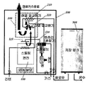
도 1에 도시된 바와 같이, 소형 열병합발전기는 하우징(100)을 포함하며, 상기 하우징(100) 내부에는 스털링 엔진(110)이 설치되고, 상기 스털링 엔진(110)의 상부에는 보조보일러(200)가 설치된다.
이때, 상기 스털링 엔진(110)은 주보일러(미도시)에 의해 가동되는데, 주보일러에 구비된 엔진버너(120)가 스털링 엔진(110)의 엔진헤드(미도시)를 가열하면 내부에 밀봉된 작동유체가 온도차에 의해 팽창/수축하면서 작동하여 교류 전류를 생산하게 된다.
그리고 상기 보조보일러(200)는 현열 열교환기(210)와 잠열 열교환기(220)를 갖추고 평판형 버너를 통해 공급되는 고열의 열교환을 통해 온수를 생산하게 된다.
이 과정에서 생산된 온수는 저장탱크(300)에 저장된 후 활용되게 되는데, 이 경우 상기 스털링 엔진(110)을 냉각하기 위해 냉각수관(130)이 스털링 엔진(110)을 경유한 후 상기 잠열 열교환기(220)와 현열 열교환기(210)를 순차로 거치도록 구성된다.
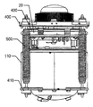
상기와 같은 소형 열병합발전기에 구비되는 스털링 엔진(110)은, 도 2 및 도 3에 도시된 바와 같이 단면의 형상이 '凹'형인 엔진 마운팅 브라켓(400)과, 상기 엔진 마운팅 브라켓(400)의 하부에 구비되는 고정 브라켓(410)이 하우징(100)에 접합 고정되며, 상기 엔진 마운팅 브라켓(400)와 고정 브라켓(410) 사이에 구비되되 상기 엔진 마운팅 브라켓(400)에 스털링 엔진(110)의 상부 일부가 관통결합된다.
또한, 상기 엔진 마운팅 브라켓(400)과 고정 브라켓(410)의 네 모서리 영역에 각각 스프링(500)이 결합되는데, 상기 스프링(500)의 상부는 엔진 마운팅 브라켓(400)에, 하부는 고정브라켓(410)에 결합되어 상기 스털링 엔진(110)은 탄성으로 지지하게 된다. 즉 상기 스털링 엔진(110)은 공중에 뜬 상태로 상기 스프링(500)에 의해 지지되는 구조이다.
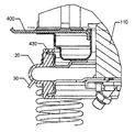
또한, 스털링 엔진(110)과 엔진 마운팅 브라켓(400)이 결합부분의 하부에는 엔진 브라켓(430)이 구비되고 상기 엔진 브라켓(430)의 하부 일부와 스털링 엔진(110)의 표면을 밀폐되도록 감싸되 그 단면의 형상이 오메가(Ω) 형상의 씰(20)이 결합된다.
상기한 씰(20)의 내측으로 스털링엔진(110) Micro-CHP의 환수온도가 낮을 경우(30℃이하) 엔진 브라켓(430) 표면에서 배기가스가 응축되어 씰(20)의 내측에 응축수가 유입되어 고이게 된다.
상기 응축수는 산성을 띄고 있으며, 이러한 응축수가 장시간 씰(20)의 내측에 머물 경우 씰이 열화 및 산화되어 누수가 발생하고, 이로 인하여 누전 등의 전기적인 위험이 발생할 수 있는 문제점이 있다.
본 발명은 상기한 종래의 문제점을 해결하기 위해 발명된 것으로, 스털링엔진을 감싸는 씰의 외측에 응축수를 배출할 수 있도록 배출구를 형성하여 응축수가 용이하게 배출될 수 있도록 하는 스털링엔진의 응축수 배출구조를 제공하는 데 그 목적이 있다.
상기한 기술적 과제를 달성하기 위한 본 발명은 엔진버너로 가열되어 전기를 생산하는 스털링엔진과, 상기 스털링엔진 상부에 설치되고 현열 열교환기 및 잠열 열교환기를 구비하여 온수를 생산하는 보조보일러를 포함하는 소형 열병합발전기에 있어서, 상기 스털링엔진의 상부 둘레를 감싸도록 구비되는 엔진브라켓; 상기 엔진브라켓을 보호하면서 상기 스털링 엔진의 표면의 일부를 감싸며, 그 단면의 형상이 Ω형으로 형성되는 씰 및 상기 씰 하부 일측에 상기 씰의 내측에 배기가스가 응축된 응축수가 배출되도록 하기 위한 배출구를 포함한다.
일 실시예에 있어서, 상기 배출구에는, 상기 배출구에 삽입되어 씰에 고이는 응축수를 보조보일러의 응축수 배출을 위한 트랩으로 유입되도록 안내하는 호스 및 상기 호스와 연결되어 상기 트랩에 형성되는 유입부를 더 포함한다.
일 실시예에 있어서, 상기 트랩에는, 그 일측부에 응축수 배출구가 막혔을 경우 외부로 배출구가 막혔음을 알리기 위하여 유입부 일측에 제1 수위센서를 더 포함한다.
본 발명의 보일러 응축수 배출구조에 의하면, 씰 하부에 형성된 배출구를 통해 응축수가 배출될 수 있도록 하여 산성을 띤 응축수가 씰 내부에서 곧바로 배출될 수 있어 씰의 부식을 막아 씰의 수명을 연장하는 효과가 있다.
또한, 배출되는 응축수가 트랩을 통하여 배출될 때 배출이 원활하지 않을 경우 이를 감지하는 센서를 구비하여 응축수의 원활한 배출을 유도하는 효과가 있다.
도 1은 일반적인 소형 열병합발전기의 스털링 엔진 배기가스의 배기과정을 나타낸 모식도이다.
도 2는 도 1에 구비되는 스털링 엔진을 개략적으로 나타낸 정면도이다.
도 3은 도 2의 스털링 엔진, 엔진 브라켓 및 씰의 결합관계를 나타내 보인 부분확대도이다.
도 4는 본 발명의 스털링엔진의 응축수 배출구조의 모습을 나타낸 부분확대도이다.
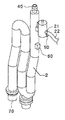
도 5는 도 4의 구성되는 씰의 배출구와 연결되는 트랩의 모습을 나타낸 도면이다.
본 발명을 충분히 이해하기 위해서 본 발명의 바람직한 실시예를 첨부 도면을 참조하여 설명한다. 본 발명의 실시예는 여러 가지 형태로 변형될 수 있으며, 본 발명의 범위가 아래에서 상세히 설명하는 실시예로 한정되는 것으로 해석되어서는 안 된다. 본 실시예는 당업계에서 평균적인 지식을 가진 자에게 본 발명을 보다 완전하게 설명하기 위하여 제공 되는 것이다. 따라서 도면에서의 요소의 형상 등은 보다 명확한 설명을 강조하기 위해서 과장되어 표현될 수 있다. 각 도면에서 동일한 부재는 동일한 참조부호로 도시한 경우가 있음을 유의하여야 한다. 또한, 본 발명의 요지를 불필요하게 흐릴 수 있다고 판단되는 공지 기능 및 구성에 대한 상세한 기술은 생략된다.
이하, 첨부된 도면을 참조하여 본 발명의 바람직한 실시예를 설명함으로써, 본 발명의 스털링엔진의 응축수 배출구조를 상세히 설명한다.
설명하기에 앞서 종래 기술과 동일한 구성의 도면부호는 동일하게 명기하기로 한다. 또한, 종래구성과 동일한 구성의 설명은 종래구성의 설명으로 대체하기로 한다.
도 4는 본 발명의 스털링엔진의 응축수 배출구조의 모습을 나타낸 부분확대도이고, 도 5는 도 4의 구성되는 씰의 배출구와 연결되는 트랩의 모습을 나타낸 도면이다.
도 4 및 도 5를 참조하면, 본 발명의 스털링엔진의 응축수 배출구조는, 엔진버너로 가열되어 전기를 생산하는 스털링엔진(110)과, 상기 스털링엔진(110) 상부에 설치되고 현열 열교환기 및 잠열 열교환기를 구비하여 온수를 생산하는 보조보일러를 포함하는 소형 열병합발전기에 있어서, 상기 스털링엔진(110)의 상부 둘레를 감싸도록 구비되는 엔진브라켓(430)과, 상기 엔진브라켓(430) 보호하면서 상기 스털링 엔진(110)의 표면의 일부를 감싸며, 그 단면의 형상이 Ω형으로 형성되는 씰(20) 및 상기 씰(20) 하부 일측에 상기 씰(20)의 내측에 배기가스가 응축된 응축수가 배출되도록 하기 위한 배출구(30)로 구성된다. 상기 엔진브라켓(430)에는 별도의 워터자켓(미도시)이 형성되어 고온의 배기가스로부터 씰(20)을 보호하게 된다.
한편, 상기 스털링 엔진(110) 및 엔진브라켓(430)을 감싸고 있는 씰(20)은 엔진과 엔진브라켓(430)과 직접 접하고 있어 스털링엔진(110)의 환수온도가 낮으면 고온의 배기가스가 응축되어 응축가스가 생성되고, 이 경우 엔진브라켓(430)의 표면을 따라 씰(20) 내부로 응축수가 유입되어 고이게 된다. 따라서 상기 배출구(30)는, 상기한 응축수를 외부로 배출하기 위한 것이다.
상기한 응축수는 산성이기 때문에 실리콘 재질로 형성되는 씰(20)의 내측에 장시간 고여 있게 되면, 씰(20)이 부식되어 크랙이 발생되고, 그 크랙을 통하여 외부로 응축수가 외부로 유출되어 전기적인 위험이 발생되는 것을 방지한다.
한편, 상기 배출구(30)에는, 상기 배출구(30)에 삽입되어 씰(20)에 고이는 응축수를 보조보일러의 응축수 배출을 위한 트랩(2)으로 유입되도록 안내하는 호스(22) 및 상기 호스(22)와 연결되어 상기 트랩(2)에 형성되는 유입부(21)가 더 구비될 수 있다.
따라서 상기 배출구(30)를 통하여 배출되는 응축수는 호스(22) 및 유입부(21)를 통하여 유입된 후 트랩(2)을 통하여 배출된다.
상기 트랩(2)은 그 상부에 보조보일러에서 발생되는 응축수가 유입되는 유입부(40)가 형성되고, 그 하부에는 배출구(70)가 형성된다.
한편, 상기 트랩(2)에는, 그 일측부에 응축수 배출구가 막혔을 경우 외부로 배출구가 막혔음을 알리기 위하여 유입부(21) 일측에 제1 수위센서(50)가 더 구비될 수 있다. 상기 제1 수위센서(50)는, 씰(20)에서의 응축수의 흐름이 원활하지 않거나 배출구가 막혔을 경우 또는 일정수위 이상이 되면 이를 감지하는 역할을 한다.
또한, 상기 트랩(2)의 외측에는 트랩(2)내에 물이 있는지 감지하는 트랩의 제2 수위센서(60)가 추가로 구비될 수 있다. 상기 제2 수위센서(60)는, 트랩(2)에 물이 없거나 오랫동안 사용하지 않아 트랩(2)의 물이 모두 증발하였을 경우 연소가스가 역류하게 되는 것이 미연에 방지하여 트랩(2)이 손상되는 것을 방지하는 역할을 한다.
이상에서 설명된 본 발명의 스털링 엔진의 응축수 배출구조의 실시예는 예시적인 것에 불과하며, 본 발명이 속한 기술분야의 통상의 지식을 가진 자라면 이로부터 다양한 변형 및 균등한 타 실시예가 가능하다는 점을 잘 알 수 있을 것이다. 그러므로 본 발명은 상기의 상세한 설명에서 언급되는 형태로만 한정되는 것은 아님을 잘 이해할 수 있을 것이다. 따라서 본 발명의 진정한 기술적 보호 범위는 첨부된 특허청구범위의 기술적 사상에 의해 정해져야 할 것이다. 또한, 본 발명은 첨부된 청구범위에 의해 정의되는 본 발명의 정신과 그 범위 내에 있는 모든 변형물과 균등물 및 대체물을 포함하는 것으로 이해되어야 한다.
[부호의 설명]
2 : 트랩 20 : 씰
21 : 유입부 22 : 호스
30 : 배출구 40 : 유입부
50 : 제1수위센서 60 : 제2수위센서
100 : 하우징 110 : 스털링 엔진
111 : 엔진 열교환기 112 : 배기가스 유로
120 : 엔진버너 400 : 엔진마운팅 브라켓
410 : 고정 브라켓 430 : 엔진 브라켓
500 : 스프링
Claims (3)
- 엔진버너로 가열되어 전기를 생산하는 스털링엔진(110)과, 상기 스털링엔진(110) 상부에 설치되고 현열 열교환기 및 잠열 열교환기를 구비하여 온수를 생산하는 보조보일러를 포함하는 소형 열병합발전기에 있어서,상기 스털링엔진(110)의 상부 둘레를 감싸도록 구비되는 엔진브라켓(430);상기 엔진브라켓(430) 보호하면서 상기 스털링 엔진(110)의 표면의 일부를 감싸며, 그 단면의 형상이 Ω형으로 형성되는 씰(20) 및상기 씰(20) 하부 일측에 상기 씰(20)의 내측에 배기가스가 응축된 응축수가 배출되도록 하기 위한 배출구(30)를 포함하는 것을 특징으로 하는 스털링엔진의 응축수 배출구조.
- 제1 항에 있어서,상기 배출구(30)에는,상기 배출구(30)에 삽입되어 씰(20)에 고이는 응축수를 보조보일러의 응축수 배출을 위한 트랩(2)으로 유입되도록 안내하는 호스(22) 및상기 호스(22)와 연결되어 상기 트랩(2)에 형성되는 유입부(21)를 더 포함하는 것을 특징으로 하는 스털링엔진의 응축수 배출구조.
- 제2 항에 있어서,상기 트랩(2)에는,그 일측부에 응축수 배출구가 막혔을 경우 외부로 배출구가 막혔음을 알리기 위하여 유입부(21) 일측에 제1 수위센서(50)를 더 포함하는 것을 특징으로 하는 스털링엔진(1)의 응축수 배출구조.
Applications Claiming Priority (2)
| Application Number | Priority Date | Filing Date | Title |
|---|---|---|---|
| KR10-2012-0009341 | 2012-01-31 | ||
| KR1020120009341A KR20130088236A (ko) | 2012-01-31 | 2012-01-31 | 스털링엔진의 응축수 배출구조 |
Publications (1)
| Publication Number | Publication Date |
|---|---|
| WO2013115503A1 true WO2013115503A1 (ko) | 2013-08-08 |
Family
ID=48905493
Family Applications (1)
| Application Number | Title | Priority Date | Filing Date |
|---|---|---|---|
| PCT/KR2013/000286 Ceased WO2013115503A1 (ko) | 2012-01-31 | 2013-01-14 | 스털링엔진의 응축수 배출구조 |
Country Status (2)
| Country | Link |
|---|---|
| KR (1) | KR20130088236A (ko) |
| WO (1) | WO2013115503A1 (ko) |
Citations (3)
| Publication number | Priority date | Publication date | Assignee | Title |
|---|---|---|---|---|
| JP2538909B2 (ja) * | 1987-03-19 | 1996-10-02 | 株式会社東芝 | スタ−リングエンジン用加熱器 |
| KR20080027857A (ko) * | 2005-06-21 | 2008-03-28 | 마이크로젠 에너지 리미티드 | 스털링 엔진 어셈블리와 그 조립방법 |
| KR20080063312A (ko) * | 2005-10-18 | 2008-07-03 | 린나이가부시기가이샤 | 코제네레이션 시스템 |
-
2012
- 2012-01-31 KR KR1020120009341A patent/KR20130088236A/ko not_active Ceased
-
2013
- 2013-01-14 WO PCT/KR2013/000286 patent/WO2013115503A1/ko not_active Ceased
Patent Citations (3)
| Publication number | Priority date | Publication date | Assignee | Title |
|---|---|---|---|---|
| JP2538909B2 (ja) * | 1987-03-19 | 1996-10-02 | 株式会社東芝 | スタ−リングエンジン用加熱器 |
| KR20080027857A (ko) * | 2005-06-21 | 2008-03-28 | 마이크로젠 에너지 리미티드 | 스털링 엔진 어셈블리와 그 조립방법 |
| KR20080063312A (ko) * | 2005-10-18 | 2008-07-03 | 린나이가부시기가이샤 | 코제네레이션 시스템 |
Also Published As
| Publication number | Publication date |
|---|---|
| KR20130088236A (ko) | 2013-08-08 |
Similar Documents
| Publication | Publication Date | Title |
|---|---|---|
| JP5358329B2 (ja) | コージェネレーション装置 | |
| CA2679811C (en) | High efficiency feedwater heater | |
| WO2013115500A1 (ko) | 냉각라인이 형성되는 잠열 열교환기 커버 | |
| WO2012023678A1 (ko) | 소형 열병합발전기의 보조보일러 배기구조 및 소형 열병합발전기의 보조보일러 배기유로 형성용 커버조립체 | |
| EP0343867B1 (en) | Hot water supply system utilizing exhaust gas of engine | |
| MX2012005081A (es) | Intercambiador de calor para evaporacion directa en sistemas de ciclo rankine organico y metodo. | |
| CN211737227U (zh) | 一种排气余热回收系统 | |
| KR100691029B1 (ko) | 이중관이 구비된 온수공급장치 | |
| KR101183815B1 (ko) | 소형 열병합발전기에서 엔진 배기유로의 배출구조 | |
| ITBS20100046A1 (it) | Impianto orc cogenerativo | |
| WO2013115503A1 (ko) | 스털링엔진의 응축수 배출구조 | |
| JP5406001B2 (ja) | 潜熱回収ユニット | |
| KR101614155B1 (ko) | 스털링엔진의 내부 응축수 발생 억제 구조 | |
| RU81259U1 (ru) | Тепловая электрическая станция | |
| KR100568779B1 (ko) | 콘덴싱 기름보일러 | |
| WO2014171623A1 (ko) | 유기 랭킨 사이클 시스템과 그 제어 장치 및 제어 방법 | |
| CN102942967A (zh) | 高炉煤气预处理方法及装置 | |
| RU2561780C2 (ru) | Парогазовая установка | |
| CA2573993A1 (en) | A method of and an apparatus for protecting a heat exchanger and a steam boiler provided with an apparatus for protecting a heat exchanger | |
| CN205690492U (zh) | 一种空气源热电热泵地暖装置 | |
| WO2013089314A1 (ko) | 폐열회수를 이용한 과열증기발생장치 | |
| KR101191585B1 (ko) | 소형 열병합발전기의 보조보일러 배기유로 형성용 커버조립체 | |
| KR102772720B1 (ko) | 폐열회수 열매체 무압 보일러 | |
| KR20120111691A (ko) | 보일러폐열회수장치 | |
| CN205447693U (zh) | 高效密闭蒸汽循环传热装置 |
Legal Events
| Date | Code | Title | Description |
|---|---|---|---|
| 121 | Ep: the epo has been informed by wipo that ep was designated in this application |
Ref document number: 13743002 Country of ref document: EP Kind code of ref document: A1 |
|
| NENP | Non-entry into the national phase |
Ref country code: DE |
|
| 122 | Ep: pct application non-entry in european phase |
Ref document number: 13743002 Country of ref document: EP Kind code of ref document: A1 |