WO2013115404A1 - Coiled spring and manufacturing method therefor - Google Patents
Coiled spring and manufacturing method therefor Download PDFInfo
- Publication number
- WO2013115404A1 WO2013115404A1 PCT/JP2013/052641 JP2013052641W WO2013115404A1 WO 2013115404 A1 WO2013115404 A1 WO 2013115404A1 JP 2013052641 W JP2013052641 W JP 2013052641W WO 2013115404 A1 WO2013115404 A1 WO 2013115404A1
- Authority
- WO
- WIPO (PCT)
- Prior art keywords
- coil spring
- residual stress
- hardness
- spring
- section
- Prior art date
Links
Images
Classifications
-
- C—CHEMISTRY; METALLURGY
- C21—METALLURGY OF IRON
- C21D—MODIFYING THE PHYSICAL STRUCTURE OF FERROUS METALS; GENERAL DEVICES FOR HEAT TREATMENT OF FERROUS OR NON-FERROUS METALS OR ALLOYS; MAKING METAL MALLEABLE, e.g. BY DECARBURISATION OR TEMPERING
- C21D7/00—Modifying the physical properties of iron or steel by deformation
- C21D7/02—Modifying the physical properties of iron or steel by deformation by cold working
- C21D7/04—Modifying the physical properties of iron or steel by deformation by cold working of the surface
- C21D7/06—Modifying the physical properties of iron or steel by deformation by cold working of the surface by shot-peening or the like
-
- C—CHEMISTRY; METALLURGY
- C21—METALLURGY OF IRON
- C21D—MODIFYING THE PHYSICAL STRUCTURE OF FERROUS METALS; GENERAL DEVICES FOR HEAT TREATMENT OF FERROUS OR NON-FERROUS METALS OR ALLOYS; MAKING METAL MALLEABLE, e.g. BY DECARBURISATION OR TEMPERING
- C21D9/00—Heat treatment, e.g. annealing, hardening, quenching or tempering, adapted for particular articles; Furnaces therefor
- C21D9/02—Heat treatment, e.g. annealing, hardening, quenching or tempering, adapted for particular articles; Furnaces therefor for springs
-
- C—CHEMISTRY; METALLURGY
- C22—METALLURGY; FERROUS OR NON-FERROUS ALLOYS; TREATMENT OF ALLOYS OR NON-FERROUS METALS
- C22C—ALLOYS
- C22C38/00—Ferrous alloys, e.g. steel alloys
- C22C38/02—Ferrous alloys, e.g. steel alloys containing silicon
-
- C—CHEMISTRY; METALLURGY
- C22—METALLURGY; FERROUS OR NON-FERROUS ALLOYS; TREATMENT OF ALLOYS OR NON-FERROUS METALS
- C22C—ALLOYS
- C22C38/00—Ferrous alloys, e.g. steel alloys
- C22C38/04—Ferrous alloys, e.g. steel alloys containing manganese
-
- C—CHEMISTRY; METALLURGY
- C22—METALLURGY; FERROUS OR NON-FERROUS ALLOYS; TREATMENT OF ALLOYS OR NON-FERROUS METALS
- C22C—ALLOYS
- C22C38/00—Ferrous alloys, e.g. steel alloys
- C22C38/08—Ferrous alloys, e.g. steel alloys containing nickel
-
- C—CHEMISTRY; METALLURGY
- C21—METALLURGY OF IRON
- C21D—MODIFYING THE PHYSICAL STRUCTURE OF FERROUS METALS; GENERAL DEVICES FOR HEAT TREATMENT OF FERROUS OR NON-FERROUS METALS OR ALLOYS; MAKING METAL MALLEABLE, e.g. BY DECARBURISATION OR TEMPERING
- C21D2211/00—Microstructure comprising significant phases
- C21D2211/001—Austenite
-
- C—CHEMISTRY; METALLURGY
- C21—METALLURGY OF IRON
- C21D—MODIFYING THE PHYSICAL STRUCTURE OF FERROUS METALS; GENERAL DEVICES FOR HEAT TREATMENT OF FERROUS OR NON-FERROUS METALS OR ALLOYS; MAKING METAL MALLEABLE, e.g. BY DECARBURISATION OR TEMPERING
- C21D2211/00—Microstructure comprising significant phases
- C21D2211/002—Bainite
-
- C—CHEMISTRY; METALLURGY
- C21—METALLURGY OF IRON
- C21D—MODIFYING THE PHYSICAL STRUCTURE OF FERROUS METALS; GENERAL DEVICES FOR HEAT TREATMENT OF FERROUS OR NON-FERROUS METALS OR ALLOYS; MAKING METAL MALLEABLE, e.g. BY DECARBURISATION OR TEMPERING
- C21D2211/00—Microstructure comprising significant phases
- C21D2211/008—Martensite
Definitions
- the present invention relates to a coil spring having excellent fatigue resistance, and more particularly to a coil spring having both end faces seated and a manufacturing method thereof.
- JIS standards include carbon steel oil temper wires (SWO-V), Cr-V steel oil temper wires (SWOCV-V), and Si-Cr steel oil temper wires (SWOSC-V).
- SWO-V carbon steel oil temper wires
- SWOCV-V Cr-V steel oil temper wires
- Si-Cr steel oil temper wires Conventionally, Si-Cr steel oil tempered wires have been widely used from the viewpoint of fatigue resistance and sag resistance.
- weight reduction of valve springs in order to improve the fuel efficiency of automobiles, and the tensile strength of strands tends to increase in order to increase the design stress of the springs.
- the metal structure is tempered martensite, such as JIS standard oil tempered wire
- the notch susceptibility to defects increases remarkably as the strength of the wire increases.
- breakage during (coiling) and a tendency to show a brittle fracture form during use become strong.
- Patent Document 1 describes a spring having excellent fatigue resistance manufactured by using an oil tempered wire in which an element such as V is added to a chemical component of JIS standard steel.
- an element such as V
- these additive elements increase the toughness of the steel material by refining crystal grains and the like, and certainly contribute to the improvement of fatigue resistance, but there is a problem that the material cost increases.
- Patent Document 2 describes a Si-killed steel wire spring having excellent fatigue characteristics formed by using a steel material with an added amount of Ba, Al, Si, Mg or Ca adjusted. However, in order to contain these additive elements in a well-balanced manner, it is presumed that management in the steel refining process becomes extremely difficult, resulting in high costs.
- Patent Document 3 discloses a spring having excellent fatigue strength by adjusting the chemical composition of steel to reduce the size of inclusions that become fatigue starting points and to reduce the crystal grain size.
- Patent Document 3 describes that a nitriding treatment is added to obtain higher fatigue strength.
- nitriding is expected to improve fatigue resistance by increasing the surface hardness, it is necessary to completely remove iron nitride on the surface layer, which can cause a decrease in fatigue strength after nitriding, and the manufacturing process is complicated. And the cost of nitriding treatment is high, resulting in high cost.
- Patent Document 4 the difference (residual stress difference) between the coil inner side and the coil outer side after forming the coil spring (residual stress difference) is set to 500 MPa using a hard drawn wire ((ferrite + pearlite) structure or drawn wire with a pearlite structure).
- a hard spring having excellent fatigue strength which is achieved by controlling the following, is disclosed.
- Patent document 4 has the merit of reducing the cost of quenching and tempering treatment necessary for producing an oil tempered wire that has been widely used in the past, but in order to reduce the residual stress difference to 500 MPa or less, the chemical composition of steel In addition to adjusting the spring strength, it is necessary to anneal at 400 ° C. or higher after forming the spring, resulting in a decrease in the strength of the material. As a result, it has been difficult to obtain a high-strength spring that can meet recent demands.
- Patent Document 5 discloses a high fatigue strength spring steel wire excellent in cold spring formability by adding Mo or V to a chemical component of JIS standard spring steel and performing austempering treatment. This technique aims to reduce the tensile residual stress inside the coil remaining after cold spring forming by setting the yield ratio (ratio of yield strength to tensile strength) to 0.85 or less.
- Patent Documents 1 to 5 it is considered that the yield of the product is bad or excessive cost is required to improve the yield.
- the present invention has been made in order to solve the above-described problems of the prior art, and reduces the material cost and simplifies the manufacturing process without reducing the yield, and also provides a coil spring excellent in fatigue resistance and its An object is to provide a manufacturing method.
- the present inventors have intensively studied the fatigue strength of high-strength valve springs. As a result, the residual stress generated after coiling can be reduced to some extent by adjusting the steel components and annealing conditions after coiling, but it is fundamental to make the steel harmless against fatigue while maintaining high strength. As a result, it was concluded that it is effective to heat the spring to the austenitizing temperature after coiling so that the residual stress generated by coiling is substantially zero.
- the austenitizing temperature of the spring that has been heated to the austenitizing temperature is subsequently subjected to austempering treatment under specific conditions, and the fatigue resistance of the base material itself is improved by making the structure excellent in the balance between strength, ductility, and toughness. I found out.
- the free length of the springs that have been dispersed due to deformation caused by the austempering treatment is made uniform to prevent a reduction in yield, and then by performing shot peening, Residual austenite in the surface layer is transformed into martensite by processing-induced transformation, and at this time, due to volume expansion, a high and deep compressive residual stress is formed in the surface layer, contributing to the improvement of fatigue resistance by suppressing the progress of fatigue cracks. I found out.
- the inventors of the present invention can use a low-priced material such as a JIS standard oil tempered wire or a hard-drawn wire having the same composition as the coil spring in which a high and deep compressive residual stress is formed on the surface layer. If a suitable thermal history condition is selected to form a predetermined structure and the alloy element concentration condition is satisfied, it can be manufactured by using ordinary shot peening in a later process without using a complicated heat treatment process. I found.
- the conventional stress relief annealing after coiling can be omitted by performing a heat treatment to reduce the residual stress after coiling, and the conventional nitriding treatment is omitted.
- the processing cost can be reduced and the process can be simplified by having high fatigue resistance according to the market demand.
- the coil spring of the present invention has been made based on the above findings, and in mass%, C: 0.5 to 0.7%, Si: 1.0 to 2.0%, Mn: 0.1 to 1 0.0%, Cr: 0.1 to 1.0%, P: 0.035% or less, S: 0.035% or less, the remainder having a component composed of iron and inevitable impurities, and any strand cross section ,
- the area ratio is 65% or more of bainite and 4 to 13% of retained austenite, and the average C concentration in the retained austenite is 0.65 to 1.7%.
- a compressive residual stress layer is formed in the range of 0.35 mm to D / 4 from the surface, and its maximum compressive residual
- the stress is 800 to 2000 MPa
- Has a hardness of 550 to 650 HV a high hardness layer 50 to 500 HV larger than the hardness at the center is formed in a depth range of 0.05 to 0.3 mm from the surface, and both end faces are ground flat. It is characterized by that.
- the manufacturing method of the coil spring of the present invention is, in mass%, C: 0.5 to 0.7%, Si: 1.0 to 2.0%, Mn: 0.1 to 1.0%, Cr : 0.1 to 1.0%, P: 0.035% or less, S: 0.035% or less, the forming step of forming a wire rod having a component consisting of iron and inevitable impurities into a coil spring, and Ac3 point After austenitizing at a temperature of ⁇ (Ac3 point + 250 ° C), cool at a rate of 20 ° C / second or more, hold at a temperature of Ms point ⁇ (Ms point + 60 ° C) for 400 seconds or more, then 20 ° C / second or more A heat treatment process for cooling to room temperature at a cooling rate of, a seat polishing process for flatly grinding both end faces of the coil spring after the heat treatment process, and a shot peening process for projecting shots to the coil spring after the seat polishing process. It is characterized by that.
- the Ac3 point is a boundary temperature at which the material shifts from a ferrite + austenite two-phase region to an austenite single-phase region during heating
- the Ms point is a temperature at which martensite starts to form during cooling.
- the “center” in the present invention means the center of a circle if the cross section is circular, but means the center of gravity if it is not circular, such as a short shape or an ellipse.
- a steel wire having a spring steel composition of JIS standard that does not contain an expensive alloy element and is easily available, and does not require complicated heat treatment or surface hardening treatment, and has a high hardness layer on the wire surface layer.
- a spring having a thick high compressive residual stress layer and excellent fatigue resistance can be obtained.
- the spring of the present invention has a small amount of alloying elements and is excellent in recyclability, and can simplify the manufacturing process and improve productivity and save energy by shortening the processing time.
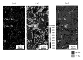
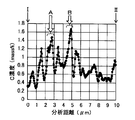
- the organization chart which shows the observation result (a) by the backscattered electron image in the same area of a strand cross section, the measurement result (b) by a C element map, and the measurement result (c) by a crystal structure (phase) map It is. It is a graph which shows the C density
- C 0.5 to 0.7% C is an important element for securing a high strength of 1800 MPa or more and for obtaining a desired retained austenite ratio at room temperature, and it is necessary to contain 0.5% or more. However, if the C concentration is excessive, the ratio of retained austenite, which is a soft phase, is excessively increased and it becomes difficult to obtain a desired strength.
- Si 1.0 to 2.0% Si has the effect of suppressing the formation of carbides from austenite when C is discharged from bainitic ferrite, which is a constituent of bainite, to austenite, and C, which is a requirement of the present invention, is dissolved in a high concentration. It is an indispensable element to obtain retained austenite. Further, it is an element that contributes to solid solution strengthening, and is an element effective for obtaining high strength. However, if the amount of Si is excessive, the ratio of soft retained austenite is increased, and conversely, the strength is reduced, so the content is suppressed to 2.0% or less.
- Mn 0.1 to 1.0% Mn is added as a deoxidizing element during refining.
- Mn is also an element that stabilizes austenite. Therefore, in order to obtain retained austenite that meets the requirements of the present invention, Mn is contained in an amount of 0.1% or more. On the other hand, when the content is excessive, segregation occurs and the workability is liable to be lowered.
- Cr 0.1 to 1.0% Cr is an element that can enhance the hardenability of the steel material and easily improve the high strength. Further, it has an effect of delaying the pearlite transformation, and a bainite structure can be stably obtained at the time of cooling after austenitizing heating (perlite formation is suppressed). However, if it exceeds 1.0% and contains excessively, it becomes easy to produce iron carbide, and it becomes difficult to produce retained austenite, so it is suppressed to 1.0%.
- P and S are elements that promote grain boundary fracture due to grain boundary segregation. Therefore, a lower value is desirable but an unavoidable impurity, and the upper limit is 0.35%.
- P and S are preferably 0.01% or less.
- transverse section refers to a cross section orthogonal to the longitudinal direction of the wire of the coil spring.
- Bainite 65% or more Bainite is a metal structure obtained by isothermally transforming an austenitic steel material at a temperature range of about 550 ° C. or less and exceeding the martensitic transformation start temperature. Bainitic ferrite and iron carbide Consists of.
- the base bainitic ferrite has a high dislocation density, and the iron carbide has a precipitation strengthening effect, so that the strength can be increased with a bainite structure.
- the bainite structure is a structure in which iron carbide is finely precipitated on the bainitic ferrite ground, and the decrease in grain boundary strength is small and the decrease in ductility is small even when the strength is high.
- bainite is an indispensable structure for obtaining high strength and high ductility, and its area ratio is preferably as high as possible. In order to obtain high strength and high ductility, 65% or more is necessary.
- untransformed austenite during isothermal holding becomes martensite and retained austenite by cooling to room temperature.
- the condition that the bainite area ratio is less than 65% means that the isothermal holding time is short. Since the concentration of C in the untransformed austenite at that stage is small, the martensite ratio is increased by subsequent cooling. Therefore, when the bainite area ratio is less than 65%, martensite is increased and high strength can be obtained, but notch sensitivity is remarkably increased, so that excellent fatigue resistance cannot be obtained.
- Residual austenite 4-13% Residual austenite is effective in reducing notch sensitivity due to an increase in ductility and toughness due to TRIP (Transformation-Induced Plasticity) phenomenon. Residual austenite expands in volume due to processing (or strain) induced martensitic transformation (Deformation (Strain) Induced Martensitic Transformation) at the stress concentration part at the crack tip, and compressive stress acts by the surrounding constraint force, and the degree of stress concentration It is thought that there is an effect of reducing the crack growth rate. Further, the retained austenite is transformed into martensite by processing-induced transformation in the shot peening process.
- volume expansion is accompanied, a high and deep compressive residual stress can be formed on the surface layer.
- the retained austenite ratio is lower than the inside in the surface processed layer by shot peening, but 4% or more is required in an arbitrary cross section in order to exert the above-described effect of suppressing crack propagation, and is excessive. Since the material strength is remarkably reduced, it is suppressed to 13% or less.
- Average C concentration in retained austenite 0.65 to 1.7% Residual austenite has a higher tensile strain that initiates work-induced martensitic transformation as its C concentration increases, and consequently contributes to a reduction in notch sensitivity due to high ductility and toughness.
- the volume expansion coefficient in the processing-induced martensitic transformation of retained austenite is larger as the C concentration of retained austenite is higher, and it promotes relaxation of stress concentration at the crack tip and generation of high deep compressive residual stress. It is thought that it is effective by improving
- the average C concentration in the retained austenite needs to be 0.65% or more in order to obtain a compressive residual stress distribution (maximum compressive residual stress of 800 MPa or more) described later.
- the C concentration in the retained austenite becomes too high, the retained austenite is remarkably stabilized, so that it acts only as a soft phase without undergoing processing-induced transformation, so that the upper limit is 1.7%.
- the surface compressive residual stress is mainly given by shot peening. However, in the present invention, in addition to the compressive residual stress obtained by normal shot peening, a higher and deeper compressive residual stress is formed by the processing-induced martensitic transformation of the residual austenite originally present in the material.
- the depth of the compressive residual stress layer of the surface layer is set to 0.35 mm to D / 4 from the surface when the equivalent circle diameter of the cross section is D (mm).
- the maximum compressive residual stress of the compressive residual stress layer is 800 to 2000 MPa.
- the maximum compressive residual stress of the surface layer is desirably high in order to suppress the occurrence and development of fatigue cracks, and the maximum value needs to be 800 MPa or more in consideration of use at a high design stress.
- 2000 MPa is set as the upper limit.
- the hardness of the spring center (center of gravity) needs to be 550 HV or more in order to ensure the strength to withstand the load required for the spring.
- the hardness is excessively high, the elongation is usually reduced and the notch (crack) sensitivity of the steel material itself is increased, and the fatigue strength may be lowered.
- the high hardness layer on the surface of the spring is very effective for suppressing the occurrence of cracks and needs to be 50 HV or more larger than the hardness of the center (center of gravity).
- the upper limit of the increase width is 500 HV or less.
- the thickness of the high hardness layer is required to be 0.05 mm or more in order to suppress the occurrence of cracks, but if it is too thick, the toughness of the steel material itself is reduced, so that it is suppressed to 0.3 mm or less.
- martensite can be included, and when a desired tensile strength is ensured, the area ratio can be 5 to 30%. When the area ratio of martensite exceeds 30%, high strength can be obtained, but notch sensitivity becomes high, so that excellent fatigue resistance cannot be obtained.
- the coil spring of the present invention is austenitized at a temperature of Ac3 point to (Ac3 point + 250 ° C.) after the coiling step, and cooled at a rate of 20 ° C./second or more to the wire having the above chemical composition, and Ms point to After a heat treatment step of holding at a temperature of (Ms point + 60 ° C.) for 400 seconds or more and then cooling to room temperature at a cooling rate of 20 ° C./second or more, a seat polishing step for grinding both end faces of the spring, and then a shot peening step. Manufactured by doing.
- a hot-forged or drawn steel strip can be used as the material.
- each step will be described, and the reasons for limitation will be described as necessary.
- Coiling process is a process of cold forming into a desired coil shape.
- a method using a spring forming machine (coiling machine), a method using a cored bar, or the like may be used.
- the spring after coiling is austenitized, cooled and kept isothermal, and then cooled.
- the isothermal holding can be performed, for example, by immersing a spring in a salt bath, but is not limited thereto, and any method such as using a lead bath can be applied.
- the austenitizing temperature is from Ac3 point to (Ac3 point + 250 ° C.). If it is less than Ac3 point, it does not become austenite and a desired structure cannot be obtained. Further, at (Ac3 point + 250 ° C.) or more, the prior austenite grain size tends to be coarsened, which may cause a decrease in ductility.
- a cooling rate of 20 ° C./second or more, preferably 50 ° C./second or more.
- the temperature for isothermal holding needs to be from Ms point to (Ms point + 60 ° C.), which is a very important control factor for the method of manufacturing the spring of the present invention. Below the Ms point, martensite generated in the early stage of transformation inhibits the improvement of ductility, and the bainite ratio defined in the present invention cannot be obtained.
- the isothermal holding time needs to be 400 seconds or more, which is also a very important control factor for the production method of the present invention. If it is less than 400 seconds, the bainite transformation hardly proceeds, so that the bainite ratio is small and the structure defined in the present invention cannot be obtained. Even if the isothermal holding time is too long, the amount of bainite produced is saturated and the production cost is increased.
- the cooling rate after isothermal holding is preferably as fast as possible to obtain a uniform structure, and requires a cooling rate of 20 ° C./second or more, preferably 50 ° C./second or more. Specifically, oil cooling or water cooling is good. On the other hand, if the cooling rate is less than 20 ° C./second, the structure tends to be uneven on the steel material surface and inside, and the structure defined in the present invention may not be obtained.
- Seat polishing step This is a step of grinding both end surfaces of the spring so as to be a plane perpendicular to the axis of the spring.
- it is generally performed after strain relief annealing that reduces the strain generated by coiling.
- it is necessary to carry out the heat treatment step after the heat treatment step in order to make uniform the free length due to the deformation caused by the heat treatment.
- Shot peening process metal particles collide with a spring and compressive residual stress is imparted to the surface, thereby significantly improving the fatigue resistance of the spring.
- a higher and deeper compressive residual stress is formed by processing-induced martensitic transformation of residual austenite.
- cut wires, steel balls, high hardness particles such as FeCrB, and the like can be used.
- the compressive residual stress can be adjusted by a shot equivalent sphere diameter, a projection speed, a projection time, and a multi-stage projection method.
- Setting process Setting is optionally performed in order to improve the elastic limit by applying plastic strain and to reduce the amount of sag (permanent deformation) during use. Further, the retained austenite is transformed into work-induced martensite by setting. By performing setting at 200 to 300 ° C. (warm setting), sag resistance can be further improved.
- the tissue phase was distinguished by immersing a sample whose cross-section was polished in a 3% nital solution for several seconds and using the subsequent tissue as follows.
- bainite since bainite is easily corroded by nital, it looks black or gray in the optical micrograph, while martensite and residual austenite appear white in the optical microscope because of high corrosion resistance to nital. Utilizing this characteristic, the optical micrograph was subjected to image processing to determine the bainite (black and gray part) ratio and the total ratio of martensite and / or retained austenite (white part).
- the residual austenite ratio was obtained by using an X-ray diffraction method for a sample buffed.
- the martensite ratio was determined by subtracting the retained austenite ratio determined by X-ray diffraction from the total ratio of martensite and retained austenite determined from the optical micrograph.
- the average C concentration in the retained austenite is shown below using the lattice constant a (nm) obtained from each diffraction peak angle of (111), (200), (220) and (311) of austenite by X-ray diffraction. Calculated by the relational expression.
- FIG. 3 shows the backscattered electron image (observed by SEM (Scanning Electron Microscopy)) in the same area 1.025 mm from the outer peripheral surface of the strand cross section toward the center, the C element map (FE-EPMA (Field Emission Electron Probe) (Measurement result by Micro Analysis)), crystal structure (phase) map (measurement result by EBSD (Electron Backscatter Diffraction)), and FIG. 2 shows the C concentration analysis result of I to II linear in FIG. 1 (b). Residual austenite differs in individual C concentration, and the C concentration in the retained austenite in each of areas A and B in FIG.
- 1B is about 1.2% to 1.5% and about 1.3% to 1.7, respectively. %, which is substantially equivalent to the average C concentration of 1.22% obtained from X-ray diffraction, and therefore it can be judged that the method for measuring the C concentration in residual austenite by X-ray diffraction is appropriate.
- the Vickers hardness was measured from the outer peripheral surface of the steel material toward the center, and the thickness from the surface was measured for a high hardness layer 50HV to 500HV larger than the average Vickers hardness of the core.
- Residual stress was measured on the outer peripheral surface of the steel using an X-ray diffraction method. Moreover, the above-mentioned measurement was performed after the entire surface of the steel material was chemically polished, and the residual stress distribution in the depth direction was determined by repeating this measurement.
- No. 2 had a short isothermal holding time in the heat treatment step, the martensite ratio was high, and as a result, the bainite ratio was small, resulting in an excessive increase in the center hardness.
- No. No. 5 has an isothermal holding temperature in the heat treatment step that is too high, so that the residual austenite ratio is too high, so that the center hardness is too low. Further, even if the retained austenite is transformed into a work-induced martensite, the surrounding restraint force is small due to the low hardness, and the compressive residual stress is low and shallow.
- the spring is heated to Ac3 point to (Ac3 point + 250 ° C.) in a heating furnace to form austenite.
- the spring held in a salt bath maintained at 300 ° C. for 1200 seconds, and then cooled.
- seat polishing for grinding both end faces of the coil spring was performed.
- a numerical value 0.6 in the equation is a tolerance width, and ⁇ is a standard deviation. It was determined that the obtained Cp was 1.4 or more and sufficient process capability was obtained.
- the present invention can be applied to a coil spring that requires fatigue resistance, such as a valve spring for an engine of an automobile.
Abstract
The purpose of the present invention is to provide a coiled spring exhibiting excellent fatigue resistance, while reducing material costs and simplifying the manufacturing process thereof without reducing yields. This coiled spring has, in mass%, 0.5-0.7% of C, 1.0-2.0% of Si, 0.1-1.0% of Mn, 0.1-1.0% of Cr, not more than 0.035% of P, and not more than 0.035% of S, the remainder comprising iron and unavoidable impurities. An arbitrary wire cross section includes, expressed as an area ratio, at least 65% of bainite, and 4-13% of retained austenite. The average C concentration in the retained austenite is 0.65-1.7%. When a cross-sectional circle equivalent diameter of the wire cross section is D (mm), a compressive residual stress layer is formed extending from a surface to within the range of 0.35mm-D/4, the maximum compressive residual stress is 800-2000MPa, the hardness at the centre is 50-650HV, a high-hardness layer which is 50-500HV harder than the hardness at the centre is formed having a depth from the surface in the range of 0.05-0.3mm, and both end surfaces are ground flat.
Description
本発明は、耐疲労性に優れたコイルばねに係り、特に、両端面が座研磨されたコイルばねおよびその製造方法に関するものである。
The present invention relates to a coil spring having excellent fatigue resistance, and more particularly to a coil spring having both end faces seated and a manufacturing method thereof.
たとえば自動車のエンジン用弁ばね材料としては、JIS規格で炭素鋼オイルテンパー線(SWO−V)、Cr−V鋼オイルテンパー線(SWOCV−V)、Si−Cr鋼オイルテンパー線(SWOSC−V)などがあり、従来、耐疲労性や耐へたり性の観点からSi−Cr鋼オイルテンパー線が広く使用されている。近年、自動車の燃費向上のため弁ばねは軽量化が強く要求されており、素線の引張強さはばねの設計応力の増加を図るため上昇する傾向にある。しかしながら、JIS規格のオイルテンパー線のように、金属組織が焼戻しマルテンサイトの場合、素線の高強度化に伴い疵あるいは介在物等の欠陥に対する切欠き感受性が著しく増加するため、冷間ばね成形(コイリング)時の折損や、使用中に脆性的な破壊形態を示す傾向が強くなることが問題となっていた。
For example, as valve spring materials for automobile engines, JIS standards include carbon steel oil temper wires (SWO-V), Cr-V steel oil temper wires (SWOCV-V), and Si-Cr steel oil temper wires (SWOSC-V). Conventionally, Si-Cr steel oil tempered wires have been widely used from the viewpoint of fatigue resistance and sag resistance. In recent years, there has been a strong demand for weight reduction of valve springs in order to improve the fuel efficiency of automobiles, and the tensile strength of strands tends to increase in order to increase the design stress of the springs. However, when the metal structure is tempered martensite, such as JIS standard oil tempered wire, the notch susceptibility to defects such as wrinkles or inclusions increases remarkably as the strength of the wire increases. There has been a problem that breakage during (coiling) and a tendency to show a brittle fracture form during use become strong.
また、コイルばねにおいては、コイリング時に圧縮外力を受けた方向にはコイリング後に引張残留応力が発生し、コイリング時に引張外力を受けた方向にはコイリング後に圧縮残留応力がそれぞれ発生するため、素線の引張強さが高いほどこれら残留応力値が大きくなる傾向があった。さらに、コイルばねを圧縮変形させた場合、コイルばねの内側表面において最も高い引張応力が付加されることが知られている。したがって、冷間成形したコイルばねを圧縮変形させる場合、コイル内側はコイリング後の引張残留応力に加え、ばね圧縮時の高い引張応力が重畳し、疲労破壊の起点となる場合が多い。
Also, in coil springs, tensile residual stress is generated after coiling in the direction in which compressive external force is applied during coiling, and compressive residual stress is generated after coiling in the direction in which tensile external force is applied during coiling. These residual stress values tended to increase as the tensile strength increased. Furthermore, it is known that when the coil spring is compressed and deformed, the highest tensile stress is applied to the inner surface of the coil spring. Therefore, when compressively deforming a cold-formed coil spring, a high tensile stress at the time of spring compression is superimposed on the inside of the coil in addition to the tensile residual stress after coiling, which often becomes the starting point of fatigue failure.
そのため、ばねは高い作用応力に対して耐疲労性を維持する必要があり、これに対する一つの手段としては素線表層に高くかつ深い圧縮残留応力を形成することが挙げられる。ばねは、ショットピーニングにより素線表層に圧縮残留応力を形成することで耐疲労性を向上することが広く行われてきた。
Therefore, it is necessary for the spring to maintain fatigue resistance against high acting stress, and one means for this is to form a high and deep compressive residual stress on the wire surface layer. Springs have been widely improved in fatigue resistance by forming compressive residual stress in the surface layer of the wire by shot peening.
しかしながら、近年、素線は高硬度化に伴い降伏強度が増加し、ショットピーニングにより与えられる表層の塑性ひずみ量は減少し、圧縮残留応力層(表面から圧縮残留応力がゼロとなる位置までの距離、以下同様)を深く形成することは困難となりつつある。
However, in recent years, the yield strength of strands has increased with increasing hardness, the amount of plastic strain on the surface layer given by shot peening has decreased, and the compressive residual stress layer (the distance from the surface to the position where the compressive residual stress becomes zero) It is becoming difficult to form deeply the same).
また、ショットピーニングにより最表層の圧縮残留応力を高めることにより、表面を起点とした早期折損は抑制されつつあるものの、作用応力と残留応力の合成応力(素材内部が受ける正味応力)分布が径方向で最大となる深さは、素線径や作用応力等によるが表面から200~600μm程度の領域である。そして、その範囲の中に20μm程度の介在物が存在すると、介在物に、素材の疲労強度を上回り折損起点となる程度の応力集中が生じる。そこで、これらの課題を解決すべく以下の方法が提案されている。
In addition, by increasing the compressive residual stress of the outermost layer by shot peening, early breakage starting from the surface is being suppressed, but the distribution of combined stress (net stress received inside the material) of working stress and residual stress is radial. The maximum depth is in the region of about 200 to 600 μm from the surface, depending on the wire diameter and acting stress. If inclusions of about 20 μm are present in the range, stress concentration is generated in the inclusions so as to exceed the fatigue strength of the material and become a breakage starting point. In order to solve these problems, the following methods have been proposed.
特許文献1には、JIS規格鋼の化学成分にV等の元素を添加したオイルテンパー線材を用いて製造した耐疲労性に優れたばねについて記されている。しかし、これら添加元素は結晶粒の微細化等により鋼材の靭性を高め、確かに耐疲労性の向上に寄与するが、材料コストが高くなる問題があった。
Patent Document 1 describes a spring having excellent fatigue resistance manufactured by using an oil tempered wire in which an element such as V is added to a chemical component of JIS standard steel. However, these additive elements increase the toughness of the steel material by refining crystal grains and the like, and certainly contribute to the improvement of fatigue resistance, but there is a problem that the material cost increases.
特許文献2には、Ba、Al、Si、MgまたはCaの添加量を調整した鋼材を用いて成形した疲労特性に優れたSiキルド鋼線ばねに関して記されている。しかし、これら添加元素をバランスよく含有させるためには鋼精錬工程上の管理が著しく困難となり、結果的に高コストになってしまうことが推察される。
Patent Document 2 describes a Si-killed steel wire spring having excellent fatigue characteristics formed by using a steel material with an added amount of Ba, Al, Si, Mg or Ca adjusted. However, in order to contain these additive elements in a well-balanced manner, it is presumed that management in the steel refining process becomes extremely difficult, resulting in high costs.
特許文献3には、鋼の化学成分を調整し、疲労起点となる介在物の大きさを小さくするとともに結晶粒径を小さくすること等により疲労強度に優れたばねが開示されている。そのようなばねでは、疲労強度の増加はみられるが、その疲労強度レベル(最大せん断応力τmax=約1200MPa)は近年の軽量高強度弁ばねに要求される実用強度(τmax=約1300~1400MPa)と比較して低い。
Patent Document 3 discloses a spring having excellent fatigue strength by adjusting the chemical composition of steel to reduce the size of inclusions that become fatigue starting points and to reduce the crystal grain size. In such a spring, although an increase in fatigue strength is observed, the fatigue strength level (maximum shear stress τmax = about 1200 MPa) is a practical strength (τmax = about 1300 to 1400 MPa) required for a light weight high strength valve spring in recent years. Low compared to
また、特許文献3ではさらに高い疲労強度を得るために窒化処理を追加することが記載されている。しかしながら、窒化によって表面硬度の増加による耐疲労性の向上が見込めるものの、窒化処理後に疲労強度を低下させる原因となり得る表層の鉄窒素化物を完全に除去しなくてはならず、製造工程が複雑になり、かつ窒化処理費用も高いため結果的に高コストになる。
Further, Patent Document 3 describes that a nitriding treatment is added to obtain higher fatigue strength. However, although nitriding is expected to improve fatigue resistance by increasing the surface hardness, it is necessary to completely remove iron nitride on the surface layer, which can cause a decrease in fatigue strength after nitriding, and the manufacturing process is complicated. And the cost of nitriding treatment is high, resulting in high cost.
特許文献4には、硬引線((フェライト+パーライト)組織またはパーライト組織の伸線加工線材)を用いて、コイルばね成形後におけるコイル内側とコイル外側の残留応力の差(残留応力差)を500MPa以下に制御することによって成される疲労強度に優れた硬引きばねが開示されている。特許文献4は、従来広く使用されているオイルテンパー線を製造するために必要な焼入れ、焼戻し処理のコストを削減できるメリットはあるが、残留応力差を500MPa以下にするためには鋼の化学成分を調整する他に、ばね成形後400℃以上で焼鈍する必要があり、素材の強度が低下し、結果的に近年の要求に応えられる高強度のばねを得ることは困難であった。
In Patent Document 4, the difference (residual stress difference) between the coil inner side and the coil outer side after forming the coil spring (residual stress difference) is set to 500 MPa using a hard drawn wire ((ferrite + pearlite) structure or drawn wire with a pearlite structure). A hard spring having excellent fatigue strength, which is achieved by controlling the following, is disclosed. Patent document 4 has the merit of reducing the cost of quenching and tempering treatment necessary for producing an oil tempered wire that has been widely used in the past, but in order to reduce the residual stress difference to 500 MPa or less, the chemical composition of steel In addition to adjusting the spring strength, it is necessary to anneal at 400 ° C. or higher after forming the spring, resulting in a decrease in the strength of the material. As a result, it has been difficult to obtain a high-strength spring that can meet recent demands.
特許文献5には、JIS規格ばね鋼の化学成分にMoやV等を添加し、オーステンパー処理をした冷間ばね成形性に優れた高疲労強度ばね用鋼線が開示されている。この技術は、降伏比(引張強度に対する降伏強度の割合)を0.85以下とすることで、冷間ばね成形後に残留するコイル内側の引張残留応力を小さくすることを目的としたものである。
Patent Document 5 discloses a high fatigue strength spring steel wire excellent in cold spring formability by adding Mo or V to a chemical component of JIS standard spring steel and performing austempering treatment. This technique aims to reduce the tensile residual stress inside the coil remaining after cold spring forming by setting the yield ratio (ratio of yield strength to tensile strength) to 0.85 or less.
しかしながら、降伏比が0.85以下の線材を用いてコイリングし、かつ、冷間成形後に焼鈍を行ってもばね成形後に発生した引張残留応力を内部に亘って十分低下させることは難しく、その後ショットピーニングを行っても深い圧縮残留応力を形成することは困難であり、耐疲労性の向上にも限界があった。また、特許文献5では組織の構成や比率について記載していない。
However, it is difficult to sufficiently reduce the tensile residual stress generated after spring forming even if coiling is performed using a wire having a yield ratio of 0.85 or less and annealing is performed after cold forming. Even if peening is performed, it is difficult to form a deep compressive residual stress, and there is a limit to improving fatigue resistance. Moreover, in patent document 5, it does not describe about the structure and ratio of a structure | tissue.
加えて、特許文献1~5では、製品の歩留りが悪いか、または歩留りを向上させるためには過大な費用が必要と考えられる。
In addition, in Patent Documents 1 to 5, it is considered that the yield of the product is bad or excessive cost is required to improve the yield.
本発明は、上記従来技術の有する課題を解決するためになされたもので、歩留りを低減させることなく材料コストの低減や製造工程の簡略化を図るとともに、耐疲労性に優れたコイルばねおよびその製造方法を提供することを目的とする。
The present invention has been made in order to solve the above-described problems of the prior art, and reduces the material cost and simplifies the manufacturing process without reducing the yield, and also provides a coil spring excellent in fatigue resistance and its An object is to provide a manufacturing method.
本発明者等は、高強度弁ばねの疲労強度について鋭意研究した。その結果、コイリング後に発生する残留応力は、鋼成分やコイリング後の焼鈍条件の調整によりある程度低減させることは可能であるが、鋼の高強度を維持しつつ疲労に対して無害化することは根本的に困難であることから、コイリング後にばねをオーステナイト化温度まで加熱し、コイリングで発生した残留応力を実質的にゼロとすることが有効であるとの結論に至った。
The present inventors have intensively studied the fatigue strength of high-strength valve springs. As a result, the residual stress generated after coiling can be reduced to some extent by adjusting the steel components and annealing conditions after coiling, but it is fundamental to make the steel harmless against fatigue while maintaining high strength. As a result, it was concluded that it is effective to heat the spring to the austenitizing temperature after coiling so that the residual stress generated by coiling is substantially zero.
また、オーステナイト化温度まで加熱したばねに対して、引き続きオーステンパー処理を特定の条件で行い、強度と延性及び靭性のバランスに優れた組織とすることで、母材自体の耐疲労性が向上することを見出した。また、次いで座研磨を行うことにより、オーステンパー処理に伴う変形によりばらついたばねの自由長を、均一の長さに揃えることで歩留りの低減を防ぎ、さらに、次いでショットピーニングを行うことにより、素線表層の残留オーステナイトが加工誘起変態によりマルテンサイトに変態し、このとき体積膨張を伴うため表層に高くかつ深い圧縮残留応力が形成され、疲労き裂の進展を抑制し耐疲労性の向上に寄与することが判った。
In addition, the austenitizing temperature of the spring that has been heated to the austenitizing temperature is subsequently subjected to austempering treatment under specific conditions, and the fatigue resistance of the base material itself is improved by making the structure excellent in the balance between strength, ductility, and toughness. I found out. In addition, by performing seat polishing, the free length of the springs that have been dispersed due to deformation caused by the austempering treatment is made uniform to prevent a reduction in yield, and then by performing shot peening, Residual austenite in the surface layer is transformed into martensite by processing-induced transformation, and at this time, due to volume expansion, a high and deep compressive residual stress is formed in the surface layer, contributing to the improvement of fatigue resistance by suppressing the progress of fatigue cracks. I found out.
そして、本発明者等は、表層に高くかつ深い圧縮残留応力が形成されたコイルばねは、素材としてJIS規格のオイルテンパー線やこれと同組成の硬引線等の低廉材を用いることができる他、適切な熱履歴条件を選定して所定の組織を構成するとともに合金元素の濃度の条件を満たせば、特に複雑な熱処理工程を用いず、後の工程で通常のショットピーニングを用いることにより製造できることを見出した。また、従来行われていたコイリング後の歪取り焼鈍は、コイリング後残留応力をゼロにする熱処理を行うことで、省略することが可能となった、また、従来行われていた窒化処理を省略しても市場要求に応じた高耐疲労性を有することで処理コストの低減や工程の簡略化が図れることが判った。
The inventors of the present invention can use a low-priced material such as a JIS standard oil tempered wire or a hard-drawn wire having the same composition as the coil spring in which a high and deep compressive residual stress is formed on the surface layer. If a suitable thermal history condition is selected to form a predetermined structure and the alloy element concentration condition is satisfied, it can be manufactured by using ordinary shot peening in a later process without using a complicated heat treatment process. I found. In addition, the conventional stress relief annealing after coiling can be omitted by performing a heat treatment to reduce the residual stress after coiling, and the conventional nitriding treatment is omitted. However, it has been found that the processing cost can be reduced and the process can be simplified by having high fatigue resistance according to the market demand.
本発明のコイルばねは、上記知見に基づいてなされたもので、質量%で、C:0.5~0.7%、Si:1.0~2.0%、Mn:0.1~1.0%、Cr:0.1~1.0%、P:0.035%以下、S:0.035%以下、残部が鉄及び不可避不純物からなる成分を有し、任意の素線横断面において、面積比率でベイナイトを65%以上、残留オーステナイトを4~13%含む組織を有し、残留オーステナイト中の平均C濃度が0.65~1.7%であり、任意の素線横断面の残留応力分布において、該素線横断面の横断面円相当直径をD(mm)としたときに、圧縮残留応力層が表面から0.35mm~D/4の範囲まで形成され、その最大圧縮残留応力が800~2000MPaであり、任意の素線横断面のビッカース硬さ分布において、中心の硬さが550~650HVであり、表面から深さ0.05~0.3mmの範囲に、前記中心の硬さより50~500HV大きい高硬度層が形成され、両端面が平坦に研削されていることを特徴とする。
The coil spring of the present invention has been made based on the above findings, and in mass%, C: 0.5 to 0.7%, Si: 1.0 to 2.0%, Mn: 0.1 to 1 0.0%, Cr: 0.1 to 1.0%, P: 0.035% or less, S: 0.035% or less, the remainder having a component composed of iron and inevitable impurities, and any strand cross section , The area ratio is 65% or more of bainite and 4 to 13% of retained austenite, and the average C concentration in the retained austenite is 0.65 to 1.7%. In the residual stress distribution, when the equivalent cross-sectional diameter of the strand cross section is D (mm), a compressive residual stress layer is formed in the range of 0.35 mm to D / 4 from the surface, and its maximum compressive residual The stress is 800 to 2000 MPa, and in the Vickers hardness distribution of any strand cross section, Has a hardness of 550 to 650 HV, a high hardness layer 50 to 500 HV larger than the hardness at the center is formed in a depth range of 0.05 to 0.3 mm from the surface, and both end faces are ground flat. It is characterized by that.
また、本発明のコイルばねの製造方法は、質量%で、C:0.5~0.7%、Si:1.0~2.0%、Mn:0.1~1.0%、Cr:0.1~1.0%、P:0.035%以下、S:0.035%以下、残部が鉄及び不可避不純物からなる成分を有する線材をコイルばねに成形する成形工程と、Ac3点~(Ac3点+250℃)の温度でオーステナイト化した後、20℃/秒以上の速度で冷却し、Ms点~(Ms点+60℃)の温度で400秒以上保持し、次いで20℃/秒以上の冷却速度で室温まで冷却する熱処理工程と、熱処理工程の後にコイルばねの両端面を平坦に研削する座研磨工程と、座研磨工程の後にコイルばねにショットを投射するショットピーニング工程とを備えたことを特徴とする。
Further, the manufacturing method of the coil spring of the present invention is, in mass%, C: 0.5 to 0.7%, Si: 1.0 to 2.0%, Mn: 0.1 to 1.0%, Cr : 0.1 to 1.0%, P: 0.035% or less, S: 0.035% or less, the forming step of forming a wire rod having a component consisting of iron and inevitable impurities into a coil spring, and Ac3 point After austenitizing at a temperature of ~ (Ac3 point + 250 ° C), cool at a rate of 20 ° C / second or more, hold at a temperature of Ms point ~ (Ms point + 60 ° C) for 400 seconds or more, then 20 ° C / second or more A heat treatment process for cooling to room temperature at a cooling rate of, a seat polishing process for flatly grinding both end faces of the coil spring after the heat treatment process, and a shot peening process for projecting shots to the coil spring after the seat polishing process. It is characterized by that.
ここで、Ac3点とは材料が加熱中にフェライト+オーステナイトの2相域からオーステナイト単相域に移行する境界温度であり、Ms点とは冷却中にマルテンサイトが生成を開始する温度である。また、本発明における「中心」とは、横断面が円形であれば円の中心であるが、例えば短形や楕円形など円形でない場合には重心を意味する。
Here, the Ac3 point is a boundary temperature at which the material shifts from a ferrite + austenite two-phase region to an austenite single-phase region during heating, and the Ms point is a temperature at which martensite starts to form during cooling. The “center” in the present invention means the center of a circle if the cross section is circular, but means the center of gravity if it is not circular, such as a short shape or an ellipse.
本発明によれば、高価な合金元素を含有せず、入手が容易なJIS規格のばね鋼組成の鋼線を用い、複雑な熱処理や表面硬化処理を必要とせず、素線表層に高硬度層と厚い高圧縮残留応力層を有する耐疲労性に優れたばねを得ることができる。また、本発明のばねは、合金元素量が少なくリサイクル性にも優れ、かつ製造工程の簡略化や、処理時間の短縮化による生産性の向上や省エネルギー化が可能である。
According to the present invention, a steel wire having a spring steel composition of JIS standard that does not contain an expensive alloy element and is easily available, and does not require complicated heat treatment or surface hardening treatment, and has a high hardness layer on the wire surface layer. Thus, a spring having a thick high compressive residual stress layer and excellent fatigue resistance can be obtained. In addition, the spring of the present invention has a small amount of alloying elements and is excellent in recyclability, and can simplify the manufacturing process and improve productivity and save energy by shortening the processing time.
まず、本発明に用いる鋼の化学成分の限定理由について説明する。なお、以下の説明において「%」は「質量%」を意味する。
First, the reasons for limiting the chemical composition of the steel used in the present invention will be described. In the following description, “%” means “mass%”.
C:0.5~0.7%
Cは、1800MPa以上の高強度を確保するためと、室温で所望の残留オーステナイト比率を得るために重要な元素であり、0.5%以上含有させることが必要である。しかし、C濃度が過剰になると、軟質相である残留オーステナイト比率が増え過ぎて所望の強度を得ることが困難になるため、0.7%以下に抑える。 C: 0.5 to 0.7%
C is an important element for securing a high strength of 1800 MPa or more and for obtaining a desired retained austenite ratio at room temperature, and it is necessary to contain 0.5% or more. However, if the C concentration is excessive, the ratio of retained austenite, which is a soft phase, is excessively increased and it becomes difficult to obtain a desired strength.
Si:1.0~2.0%
Siは、ベイナイトの構成要素であるベイニティックフェライトからオーステナイトへCが排出される際にオーステナイト地からの炭化物の生成を抑制する作用を持ち、本発明の要件にあるCが高濃度で固溶した残留オーステナイトを得るためには不可欠の元素である。また固溶強化に寄与する元素であり、高強度を得るために有効な元素であるため1.0%以上含有させる。ただし、Si量が過剰であると、軟質な残留オーステナイト比率が高くなり、逆に強度の低下を招くため2.0%以下に抑える。 Si: 1.0 to 2.0%
Si has the effect of suppressing the formation of carbides from austenite when C is discharged from bainitic ferrite, which is a constituent of bainite, to austenite, and C, which is a requirement of the present invention, is dissolved in a high concentration. It is an indispensable element to obtain retained austenite. Further, it is an element that contributes to solid solution strengthening, and is an element effective for obtaining high strength. However, if the amount of Si is excessive, the ratio of soft retained austenite is increased, and conversely, the strength is reduced, so the content is suppressed to 2.0% or less.
Mn:0.1~1.0%
Mnは、精錬中の脱酸元素として添加されるが、一方でオーステナイトを安定化させる元素でもあるため、本発明の要件にある残留オーステナイトを得るためには0.1%以上含有させる。一方、含有量が過剰であると偏析が生じ加工性が低下しやすくなるため、1.0%以下に抑える。 Mn: 0.1 to 1.0%
Mn is added as a deoxidizing element during refining. On the other hand, Mn is also an element that stabilizes austenite. Therefore, in order to obtain retained austenite that meets the requirements of the present invention, Mn is contained in an amount of 0.1% or more. On the other hand, when the content is excessive, segregation occurs and the workability is liable to be lowered.
Cr:0.1~1.0%
Crは、鋼材の焼入れ性を高めて高強度を容易に向上できる元素である。また、パーライト変態を遅延させる作用もあり、オーステナイト化加熱後の冷却時に安定してベイナイト組織を得る(パーライト生成を抑制する)ことができるため、0.1%以上含有させる。ただし、1.0%を超えて過剰に含有すると鉄炭化物を生じ易くなり、残留オーステナイトが生じ難くなるため、1.0%に抑える。 Cr: 0.1 to 1.0%
Cr is an element that can enhance the hardenability of the steel material and easily improve the high strength. Further, it has an effect of delaying the pearlite transformation, and a bainite structure can be stably obtained at the time of cooling after austenitizing heating (perlite formation is suppressed). However, if it exceeds 1.0% and contains excessively, it becomes easy to produce iron carbide, and it becomes difficult to produce retained austenite, so it is suppressed to 1.0%.
P,S:0.035%以下
PおよびSは、粒界偏析による粒界破壊を助長する元素であるため、低い方が望ましいが不可避不純物であり、上限は0.35%とする。PおよびSは、好ましくは、0.01%以下である。 P, S: 0.035% or less P and S are elements that promote grain boundary fracture due to grain boundary segregation. Therefore, a lower value is desirable but an unavoidable impurity, and the upper limit is 0.35%. P and S are preferably 0.01% or less.
PおよびSは、粒界偏析による粒界破壊を助長する元素であるため、低い方が望ましいが不可避不純物であり、上限は0.35%とする。PおよびSは、好ましくは、0.01%以下である。 P, S: 0.035% or less P and S are elements that promote grain boundary fracture due to grain boundary segregation. Therefore, a lower value is desirable but an unavoidable impurity, and the upper limit is 0.35%. P and S are preferably 0.01% or less.
次に、任意の横断面における組織の面積比率の限定理由について説明する。なお、以下の説明において「横断面」とは、コイルばねの素線の長手方向と直交する断面をいう。
Next, the reason for limiting the area ratio of the tissue in an arbitrary cross section will be described. In the following description, “transverse section” refers to a cross section orthogonal to the longitudinal direction of the wire of the coil spring.
ベイナイト:65%以上
ベイナイトとは、オーステナイト化された鋼材を550℃程度以下でマルテンサイト変態開始温度を超える温度域にて等温変態させることによって得られる金属組織であり、ベイニティックフェライトと鉄炭化物で構成される。素地のベイニティックフェライトは転位密度が高く、また鉄炭化物は析出強化効果があるため、ベイナイト組織をもって強度を高めることができる。さらに、本発明の製法によれば、ベイナイト組織は鉄炭化物がベイニティックフェライト地に微細析出した構造であり、粒界強度の低下が少なく高強度であっても延靭性の低下が小さい。このように、ベイナイトは高強度と高延性を得るために不可欠な組織であり、その面積比率は高いほど望ましく、高強度及び高延性を得るためには65%以上が必要である。 Bainite: 65% or more Bainite is a metal structure obtained by isothermally transforming an austenitic steel material at a temperature range of about 550 ° C. or less and exceeding the martensitic transformation start temperature. Bainitic ferrite and iron carbide Consists of. The base bainitic ferrite has a high dislocation density, and the iron carbide has a precipitation strengthening effect, so that the strength can be increased with a bainite structure. Furthermore, according to the manufacturing method of the present invention, the bainite structure is a structure in which iron carbide is finely precipitated on the bainitic ferrite ground, and the decrease in grain boundary strength is small and the decrease in ductility is small even when the strength is high. Thus, bainite is an indispensable structure for obtaining high strength and high ductility, and its area ratio is preferably as high as possible. In order to obtain high strength and high ductility, 65% or more is necessary.
ベイナイトとは、オーステナイト化された鋼材を550℃程度以下でマルテンサイト変態開始温度を超える温度域にて等温変態させることによって得られる金属組織であり、ベイニティックフェライトと鉄炭化物で構成される。素地のベイニティックフェライトは転位密度が高く、また鉄炭化物は析出強化効果があるため、ベイナイト組織をもって強度を高めることができる。さらに、本発明の製法によれば、ベイナイト組織は鉄炭化物がベイニティックフェライト地に微細析出した構造であり、粒界強度の低下が少なく高強度であっても延靭性の低下が小さい。このように、ベイナイトは高強度と高延性を得るために不可欠な組織であり、その面積比率は高いほど望ましく、高強度及び高延性を得るためには65%以上が必要である。 Bainite: 65% or more Bainite is a metal structure obtained by isothermally transforming an austenitic steel material at a temperature range of about 550 ° C. or less and exceeding the martensitic transformation start temperature. Bainitic ferrite and iron carbide Consists of. The base bainitic ferrite has a high dislocation density, and the iron carbide has a precipitation strengthening effect, so that the strength can be increased with a bainite structure. Furthermore, according to the manufacturing method of the present invention, the bainite structure is a structure in which iron carbide is finely precipitated on the bainitic ferrite ground, and the decrease in grain boundary strength is small and the decrease in ductility is small even when the strength is high. Thus, bainite is an indispensable structure for obtaining high strength and high ductility, and its area ratio is preferably as high as possible. In order to obtain high strength and high ductility, 65% or more is necessary.
一方、等温保持中の未変態オーステナイトは、その後室温まで冷却されることによりマルテンサイトや残留オーステナイトとなる。ベイナイト面積比率が65%未満となる条件は、等温保持時間が短いことを意味し、その段階での未変態オーステナイト中のCの濃縮度は小さいため、その後の冷却によりマルテンサイト比率が高くなる。したがって、ベイナイト面積比率が65%未満となる場合は、マルテンサイトが多くなるため高強度は得られるが、切欠き感受性が著しく高くなるため、優れた耐疲労性を得ることはできない。
On the other hand, untransformed austenite during isothermal holding becomes martensite and retained austenite by cooling to room temperature. The condition that the bainite area ratio is less than 65% means that the isothermal holding time is short. Since the concentration of C in the untransformed austenite at that stage is small, the martensite ratio is increased by subsequent cooling. Therefore, when the bainite area ratio is less than 65%, martensite is increased and high strength can be obtained, but notch sensitivity is remarkably increased, so that excellent fatigue resistance cannot be obtained.
残留オーステナイト:4~13%
残留オーステナイトは、TRIP(Transformation−induced plasticity;変態誘起塑性)現象による延性及び靭性の増加に起因した切欠き感受性の低減に有効である。また、残留オーステナイトはき裂先端の応力集中部で加工(または歪み)誘起マルテンサイト変態(Deformation(Strain)Induced Martensitic Transformation)により体積膨張し、その周囲の拘束力によって圧縮応力が働き、応力集中度を軽減することでき裂の進展速度を低下させる作用があると考えられる。さらに、残留オーステナイトは、ショットピーニング工程で加工誘起変態によりマルテンサイトに変態する。このとき体積膨張を伴うため、表層に高くかつ深い圧縮残留応力を形成することができる。残留オーステナイト比率は、ショットピーニングによる表面加工層では内部よりも低くなっているが、上記したき裂の進展の抑制効果を発揮するには任意の横断面において4%以上必要であり、過剰であると材料強度の低下が著しいため、13%以下に抑える。 Residual austenite: 4-13%
Residual austenite is effective in reducing notch sensitivity due to an increase in ductility and toughness due to TRIP (Transformation-Induced Plasticity) phenomenon. Residual austenite expands in volume due to processing (or strain) induced martensitic transformation (Deformation (Strain) Induced Martensitic Transformation) at the stress concentration part at the crack tip, and compressive stress acts by the surrounding constraint force, and the degree of stress concentration It is thought that there is an effect of reducing the crack growth rate. Further, the retained austenite is transformed into martensite by processing-induced transformation in the shot peening process. At this time, since volume expansion is accompanied, a high and deep compressive residual stress can be formed on the surface layer. The retained austenite ratio is lower than the inside in the surface processed layer by shot peening, but 4% or more is required in an arbitrary cross section in order to exert the above-described effect of suppressing crack propagation, and is excessive. Since the material strength is remarkably reduced, it is suppressed to 13% or less.
残留オーステナイト中の平均C濃度:0.65~1.7%
残留オーステナイトは、そのC濃度が高いほど加工誘起マルテンサイト変態を開始する引張ひずみが高いため、結果的に高い延性及び靭性に起因した切欠き感受性の低下に寄与する。また、残留オーステナイトの加工誘起マルテンサイト変態における体積膨張率は、残留オーステナイトのC濃度が高いほど大きく、き裂先端における応力集中の緩和や高く深い圧縮残留応力の生成を促進するため、耐疲労性の向上により有効であると考えられる。残留オーステナイト中の平均C濃度は、後述する圧縮残留応力分布(800MPa以上の最大圧縮残留応力)を得るため0.65%以上必要である。一方、残留オーステナイト中のC濃度が高くなりすぎると残留オーステナイトは著しく安定化し、これにより加工誘起変態しないまま単なる軟質相としてのみ作用するため1.7%を上限とする。 Average C concentration in retained austenite: 0.65 to 1.7%
Residual austenite has a higher tensile strain that initiates work-induced martensitic transformation as its C concentration increases, and consequently contributes to a reduction in notch sensitivity due to high ductility and toughness. In addition, the volume expansion coefficient in the processing-induced martensitic transformation of retained austenite is larger as the C concentration of retained austenite is higher, and it promotes relaxation of stress concentration at the crack tip and generation of high deep compressive residual stress. It is thought that it is effective by improving The average C concentration in the retained austenite needs to be 0.65% or more in order to obtain a compressive residual stress distribution (maximum compressive residual stress of 800 MPa or more) described later. On the other hand, if the C concentration in the retained austenite becomes too high, the retained austenite is remarkably stabilized, so that it acts only as a soft phase without undergoing processing-induced transformation, so that the upper limit is 1.7%.
次に、ばねの横断面における諸特性の限定理由について説明する。
表層の圧縮残留応力分布
表層の圧縮残留応力は主にショットピーニングにより与えられる。ただし、本発明では通常のショットピーニングで得られる圧縮残留応力に加え、素材にもともと存在する残留オーステナイトの加工誘起マルテンサイト変態によりさらに高く深い圧縮残留応力が形成される。表層の圧縮残留応力層の深さは、横断面の円相当直径をD(mm)としたときに、表面から0.35mm~D/4とする。これは、表面から深さ200μm~D/4程度の範囲は、例えば、ばねの素線径が1.5~15mmの範囲において、外部負荷による作用応力と残留応力との合成応力を考慮すると、疲労破壊の起点となりやすい箇所であるため、本厚さが0.35mm未満では内部起点の疲労破壊を抑制するには不十分である。 Next, the reasons for limiting the characteristics in the cross section of the spring will be described.
Surface compressive residual stress distribution The surface compressive residual stress is mainly given by shot peening. However, in the present invention, in addition to the compressive residual stress obtained by normal shot peening, a higher and deeper compressive residual stress is formed by the processing-induced martensitic transformation of the residual austenite originally present in the material. The depth of the compressive residual stress layer of the surface layer is set to 0.35 mm to D / 4 from the surface when the equivalent circle diameter of the cross section is D (mm). This is because, in the range of about 200 μm to D / 4 from the surface, for example, in the range where the element wire diameter of the spring is 1.5 to 15 mm, considering the combined stress of the applied stress and the residual stress due to the external load, Since this is a location that tends to be a starting point for fatigue failure, if the thickness is less than 0.35 mm, it is insufficient to suppress fatigue failure at the internal starting point.
一方、上記圧縮残留応力層の厚さが厚過ぎると、鋼材全体の応力バランスを維持するために、圧縮残留応力がゼロとなる深さ(クロッシングポンイント)よりさらに内側に存在する引張残留応力が著しく高くなり、この引張応力が外部負荷によりばね素線に発生する引張応力に加わってき裂の発生を促進するため、D/4を上限とする。
On the other hand, if the thickness of the compressive residual stress layer is too thick, in order to maintain the stress balance of the entire steel material, there is a tensile residual stress existing further inside than the depth (crossing point) at which the compressive residual stress becomes zero. Since the tensile stress is remarkably increased and this tensile stress is added to the tensile stress generated in the spring element wire by an external load and promotes the generation of cracks, D / 4 is set as the upper limit.
上記圧縮残留応力層の最大圧縮残留応力は800~2000MPaとする。表層の最大圧縮残留応力は疲労亀裂の発生および進展を抑制するために高いことが望ましく、高設計応力で使用することを考慮すると、最大値は800MPa以上必要である。一方、表層の最大圧縮残留応力が著しく高い場合、前述したようにクロッシングポイントより深い内部での応力バランスに起因した引張残留応力により内部破壊が発生する恐れが強まるため、2000MPaを上限とする。
The maximum compressive residual stress of the compressive residual stress layer is 800 to 2000 MPa. The maximum compressive residual stress of the surface layer is desirably high in order to suppress the occurrence and development of fatigue cracks, and the maximum value needs to be 800 MPa or more in consideration of use at a high design stress. On the other hand, when the maximum compressive residual stress of the surface layer is remarkably high, the risk of internal fracture due to the tensile residual stress due to the stress balance inside deeper than the crossing point increases as described above, so 2000 MPa is set as the upper limit.
硬度分布
ばね中心(重心)の硬さはばねに必要な荷重に耐え得る強度を確保するために550HV以上必要である。一方、硬さが過剰に高い場合は通常伸びが小さくなるとともに鋼材自体の切欠き(き裂)感受性が増加し、疲労強度が低下する恐れがあるため、650HV以下に抑える。一方、ばねの表面の高硬度層はき裂の発生を抑制するために非常に効果的であり、中心(重心)の硬さより50HV以上大きいことが必要である。しかし、高硬度層の硬さが高過ぎると脆くなるため、増加幅の上限は500HV以下である。さらに上記高硬度層の厚さは、き裂の発生を抑制するため0.05mm以上必要であるが、厚過ぎると鋼材自体の靭性低下を招くため0.3mm以下に抑制する。 Hardness distribution The hardness of the spring center (center of gravity) needs to be 550 HV or more in order to ensure the strength to withstand the load required for the spring. On the other hand, when the hardness is excessively high, the elongation is usually reduced and the notch (crack) sensitivity of the steel material itself is increased, and the fatigue strength may be lowered. On the other hand, the high hardness layer on the surface of the spring is very effective for suppressing the occurrence of cracks and needs to be 50 HV or more larger than the hardness of the center (center of gravity). However, if the hardness of the high hardness layer is too high, it becomes brittle, so the upper limit of the increase width is 500 HV or less. Further, the thickness of the high hardness layer is required to be 0.05 mm or more in order to suppress the occurrence of cracks, but if it is too thick, the toughness of the steel material itself is reduced, so that it is suppressed to 0.3 mm or less.
ばね中心(重心)の硬さはばねに必要な荷重に耐え得る強度を確保するために550HV以上必要である。一方、硬さが過剰に高い場合は通常伸びが小さくなるとともに鋼材自体の切欠き(き裂)感受性が増加し、疲労強度が低下する恐れがあるため、650HV以下に抑える。一方、ばねの表面の高硬度層はき裂の発生を抑制するために非常に効果的であり、中心(重心)の硬さより50HV以上大きいことが必要である。しかし、高硬度層の硬さが高過ぎると脆くなるため、増加幅の上限は500HV以下である。さらに上記高硬度層の厚さは、き裂の発生を抑制するため0.05mm以上必要であるが、厚過ぎると鋼材自体の靭性低下を招くため0.3mm以下に抑制する。 Hardness distribution The hardness of the spring center (center of gravity) needs to be 550 HV or more in order to ensure the strength to withstand the load required for the spring. On the other hand, when the hardness is excessively high, the elongation is usually reduced and the notch (crack) sensitivity of the steel material itself is increased, and the fatigue strength may be lowered. On the other hand, the high hardness layer on the surface of the spring is very effective for suppressing the occurrence of cracks and needs to be 50 HV or more larger than the hardness of the center (center of gravity). However, if the hardness of the high hardness layer is too high, it becomes brittle, so the upper limit of the increase width is 500 HV or less. Further, the thickness of the high hardness layer is required to be 0.05 mm or more in order to suppress the occurrence of cracks, but if it is too thick, the toughness of the steel material itself is reduced, so that it is suppressed to 0.3 mm or less.
なお、本発明では、必須ではないがマルテンサイトを含むことができ、所望の引張強さを確保する場合に面積比率で5~30%存在させることができる。マルテンサイトの面積比率が30%を超えると高強度は得られるが、切欠き感受性が高くなるため、優れた耐疲労性を得ることはできない。
In the present invention, although not essential, martensite can be included, and when a desired tensile strength is ensured, the area ratio can be 5 to 30%. When the area ratio of martensite exceeds 30%, high strength can be obtained, but notch sensitivity becomes high, so that excellent fatigue resistance cannot be obtained.
次に、本発明のコイルばねの製造方法について説明する。本発明のコイルばねは、上記化学成分の線材に対し、コイリング工程の後、Ac3点~(Ac3点+250℃)の温度でオーステナイト化後、20℃/秒以上の速度で冷却し、Ms点~(Ms点+60℃)の温度で400秒以上保持し、次いで20℃/秒以上の冷却速度で室温まで冷却する熱処理工程の後、ばねの両端面を研削する座研磨工程後、ショットピーニング工程を行うことによって製造される。Ac3点以上に加熱する前の鋼の組織については特に制限されない。例えば、熱間鍛造や線引き加工した条鋼材を素材として使用できる。以下に、各工程について説明し、必要に応じて限定理由を述べる。
Next, a method for manufacturing the coil spring of the present invention will be described. The coil spring of the present invention is austenitized at a temperature of Ac3 point to (Ac3 point + 250 ° C.) after the coiling step, and cooled at a rate of 20 ° C./second or more to the wire having the above chemical composition, and Ms point to After a heat treatment step of holding at a temperature of (Ms point + 60 ° C.) for 400 seconds or more and then cooling to room temperature at a cooling rate of 20 ° C./second or more, a seat polishing step for grinding both end faces of the spring, and then a shot peening step. Manufactured by doing. There is no particular limitation on the structure of the steel before heating to Ac3 point or higher. For example, a hot-forged or drawn steel strip can be used as the material. Hereinafter, each step will be described, and the reasons for limitation will be described as necessary.
コイリング工程
コイリング工程は、所望のコイル形状に冷間成形する工程である。成形方法はばね形成機(コイリングマシン)を用いる方法や、芯金を用いる方法等を利用すればよい。 Coiling process The coiling process is a process of cold forming into a desired coil shape. As a forming method, a method using a spring forming machine (coiling machine), a method using a cored bar, or the like may be used.
コイリング工程は、所望のコイル形状に冷間成形する工程である。成形方法はばね形成機(コイリングマシン)を用いる方法や、芯金を用いる方法等を利用すればよい。 Coiling process The coiling process is a process of cold forming into a desired coil shape. As a forming method, a method using a spring forming machine (coiling machine), a method using a cored bar, or the like may be used.
熱処理工程
コイリング後のばねをオーステナイト化後、冷却して等温保持し、その後冷却する処理である。等温保持は例えばソルトバスにばねを浸漬することで行うことができるが、それに限定されるものではなく鉛浴を用いるなど任意の方法を適用することができる。オーステナイト化を行う前の鋼の組織については特に制限されない。たとえば、熱間鍛造や線引き加工した条鋼材を素材として使用できる。オーステナイト化の温度は、Ac3点~(Ac3点+250℃)である。Ac3点未満ではオーステナイト化せず、所望の組織を得ることができない。また、(Ac3点+250℃)以上では、旧オーステナイト粒径が粗大化しやすくなり、延性の低下を招く恐れがある。 Heat treatment process The spring after coiling is austenitized, cooled and kept isothermal, and then cooled. The isothermal holding can be performed, for example, by immersing a spring in a salt bath, but is not limited thereto, and any method such as using a lead bath can be applied. There are no particular restrictions on the structure of the steel before austenitization. For example, it is possible to use a hot-forged or drawn steel bar material as a raw material. The austenitizing temperature is from Ac3 point to (Ac3 point + 250 ° C.). If it is less than Ac3 point, it does not become austenite and a desired structure cannot be obtained. Further, at (Ac3 point + 250 ° C.) or more, the prior austenite grain size tends to be coarsened, which may cause a decrease in ductility.
コイリング後のばねをオーステナイト化後、冷却して等温保持し、その後冷却する処理である。等温保持は例えばソルトバスにばねを浸漬することで行うことができるが、それに限定されるものではなく鉛浴を用いるなど任意の方法を適用することができる。オーステナイト化を行う前の鋼の組織については特に制限されない。たとえば、熱間鍛造や線引き加工した条鋼材を素材として使用できる。オーステナイト化の温度は、Ac3点~(Ac3点+250℃)である。Ac3点未満ではオーステナイト化せず、所望の組織を得ることができない。また、(Ac3点+250℃)以上では、旧オーステナイト粒径が粗大化しやすくなり、延性の低下を招く恐れがある。 Heat treatment process The spring after coiling is austenitized, cooled and kept isothermal, and then cooled. The isothermal holding can be performed, for example, by immersing a spring in a salt bath, but is not limited thereto, and any method such as using a lead bath can be applied. There are no particular restrictions on the structure of the steel before austenitization. For example, it is possible to use a hot-forged or drawn steel bar material as a raw material. The austenitizing temperature is from Ac3 point to (Ac3 point + 250 ° C.). If it is less than Ac3 point, it does not become austenite and a desired structure cannot be obtained. Further, at (Ac3 point + 250 ° C.) or more, the prior austenite grain size tends to be coarsened, which may cause a decrease in ductility.
オーステナイト化後に等温保持する温度までの冷却速度は速いほど良く、20℃/秒以上の冷却速度で行う必要があり、好ましくは50℃/秒以上である。この冷却速度が20℃/秒未満では、冷却途中でパーライトが生成し、本発明で規定する組織構成を得ることができない。等温保持する温度はMs点~(Ms点+60℃)である必要があり、これは本発明のばねの製造方法として非常に重要な制御因子である。Ms点未満では変態初期に生成するマルテンサイトが延性の向上を阻害するほか、本発明で規定するベイナイト比率を得ることができない。
The faster the cooling rate to the temperature at which the temperature is kept isothermal after austenite is better, it is necessary to carry out at a cooling rate of 20 ° C./second or more, preferably 50 ° C./second or more. When the cooling rate is less than 20 ° C./second, pearlite is generated during the cooling, and the structure defined in the present invention cannot be obtained. The temperature for isothermal holding needs to be from Ms point to (Ms point + 60 ° C.), which is a very important control factor for the method of manufacturing the spring of the present invention. Below the Ms point, martensite generated in the early stage of transformation inhibits the improvement of ductility, and the bainite ratio defined in the present invention cannot be obtained.
一方、等温保持する温度が(Ms点+60℃)を超える場合は、残留オーステナイト比率が高くなり過ぎ、引張強さが低下し、コイルばねとして荷重に耐える強度を得ることができない。等温保持する時間は、400秒以上である必要があり、これも本発明の製造方法として非常に重要な制御因子である。400秒未満ではベイナイト変態がほとんど進行しないため、ベイナイト比率が小さく、本発明に規定する組織を得ることはできない。なお、等温保持する時間が長過ぎても生成されるベイナイト量は飽和し、生産コストの増大を招くので、3時間以内とするのが望ましい。
On the other hand, when the isothermal holding temperature exceeds (Ms point + 60 ° C.), the retained austenite ratio becomes too high, the tensile strength decreases, and the coil spring cannot obtain the strength that can withstand the load. The isothermal holding time needs to be 400 seconds or more, which is also a very important control factor for the production method of the present invention. If it is less than 400 seconds, the bainite transformation hardly proceeds, so that the bainite ratio is small and the structure defined in the present invention cannot be obtained. Even if the isothermal holding time is too long, the amount of bainite produced is saturated and the production cost is increased.
等温保持後の冷却速度は、均一な組織を得るため速いほど良く、20℃/秒以上の冷却速度が必要であり、好ましくは50℃/秒以上である。具体的には油冷や水冷が良い。一方、冷却速度が20℃/秒未満では、鋼材表面と内部で組織が不均一に成りやすく、本発明に規定する組織を得ることができない場合がある。
The cooling rate after isothermal holding is preferably as fast as possible to obtain a uniform structure, and requires a cooling rate of 20 ° C./second or more, preferably 50 ° C./second or more. Specifically, oil cooling or water cooling is good. On the other hand, if the cooling rate is less than 20 ° C./second, the structure tends to be uneven on the steel material surface and inside, and the structure defined in the present invention may not be obtained.
座研磨工程
ばねの両端面をばねの軸芯に対して直角な平面になるように研削する工程である。従来の熱処理を行わないばねの製造工程においては、コイリングで発生した歪みを低減する歪取り焼鈍の後に行われるのが一般的である。しかし、本発明においては、熱処理に伴う変形によるばらついた自由長を均一に揃える目的で行うため、熱処理工程の後に実施する必要がある。 Seat polishing step This is a step of grinding both end surfaces of the spring so as to be a plane perpendicular to the axis of the spring. In a conventional spring manufacturing process that does not perform heat treatment, it is generally performed after strain relief annealing that reduces the strain generated by coiling. However, in the present invention, it is necessary to carry out the heat treatment step after the heat treatment step in order to make uniform the free length due to the deformation caused by the heat treatment.
ばねの両端面をばねの軸芯に対して直角な平面になるように研削する工程である。従来の熱処理を行わないばねの製造工程においては、コイリングで発生した歪みを低減する歪取り焼鈍の後に行われるのが一般的である。しかし、本発明においては、熱処理に伴う変形によるばらついた自由長を均一に揃える目的で行うため、熱処理工程の後に実施する必要がある。 Seat polishing step This is a step of grinding both end surfaces of the spring so as to be a plane perpendicular to the axis of the spring. In a conventional spring manufacturing process that does not perform heat treatment, it is generally performed after strain relief annealing that reduces the strain generated by coiling. However, in the present invention, it is necessary to carry out the heat treatment step after the heat treatment step in order to make uniform the free length due to the deformation caused by the heat treatment.
ショットピーニング工程
ショットピーニングは、ばねに金属粒を衝突させ、表面に圧縮残留応力を付与するもので、これによりばねの耐疲労性が著しく向上する。本発明では通常のショットピーニングで得られる圧縮残留応力に加え、残留オーステナイトの加工誘起マルテンサイト変態によりさらに高く深い圧縮残留応力が形成される。ショットピーニングで使用するショットは、カットワイヤやスチールボール、FeCrB系などの高硬度粒子等を用いることができる。また、圧縮残留応力は、ショットの球相当直径や投射速度、投射時間、および多段階の投射方式で調整することができる。 Shot peening process In shot peening, metal particles collide with a spring and compressive residual stress is imparted to the surface, thereby significantly improving the fatigue resistance of the spring. In the present invention, in addition to the compressive residual stress obtained by normal shot peening, a higher and deeper compressive residual stress is formed by processing-induced martensitic transformation of residual austenite. For shots used in shot peening, cut wires, steel balls, high hardness particles such as FeCrB, and the like can be used. Further, the compressive residual stress can be adjusted by a shot equivalent sphere diameter, a projection speed, a projection time, and a multi-stage projection method.
ショットピーニングは、ばねに金属粒を衝突させ、表面に圧縮残留応力を付与するもので、これによりばねの耐疲労性が著しく向上する。本発明では通常のショットピーニングで得られる圧縮残留応力に加え、残留オーステナイトの加工誘起マルテンサイト変態によりさらに高く深い圧縮残留応力が形成される。ショットピーニングで使用するショットは、カットワイヤやスチールボール、FeCrB系などの高硬度粒子等を用いることができる。また、圧縮残留応力は、ショットの球相当直径や投射速度、投射時間、および多段階の投射方式で調整することができる。 Shot peening process In shot peening, metal particles collide with a spring and compressive residual stress is imparted to the surface, thereby significantly improving the fatigue resistance of the spring. In the present invention, in addition to the compressive residual stress obtained by normal shot peening, a higher and deeper compressive residual stress is formed by processing-induced martensitic transformation of residual austenite. For shots used in shot peening, cut wires, steel balls, high hardness particles such as FeCrB, and the like can be used. Further, the compressive residual stress can be adjusted by a shot equivalent sphere diameter, a projection speed, a projection time, and a multi-stage projection method.
セッチング工程
セッチングは、塑性ひずみを与えることにより、弾性限が向上することと、使用時のへたり量(永久変形量)を低減するために任意的に行う。また、セッチングにより残留オーステナイトが加工誘起マルテンサイトに変態する。200~300℃でセッチングを行う(温間セッチング)ことにより、耐へたり性を一層向上させることができる。 Setting process Setting is optionally performed in order to improve the elastic limit by applying plastic strain and to reduce the amount of sag (permanent deformation) during use. Further, the retained austenite is transformed into work-induced martensite by setting. By performing setting at 200 to 300 ° C. (warm setting), sag resistance can be further improved.
セッチングは、塑性ひずみを与えることにより、弾性限が向上することと、使用時のへたり量(永久変形量)を低減するために任意的に行う。また、セッチングにより残留オーステナイトが加工誘起マルテンサイトに変態する。200~300℃でセッチングを行う(温間セッチング)ことにより、耐へたり性を一層向上させることができる。 Setting process Setting is optionally performed in order to improve the elastic limit by applying plastic strain and to reduce the amount of sag (permanent deformation) during use. Further, the retained austenite is transformed into work-induced martensite by setting. By performing setting at 200 to 300 ° C. (warm setting), sag resistance can be further improved.
表1に示す成分からなるオイルテンパー線材を用いて、コイリングマシンにより所定形状に冷間コイリング後、表3に記載の条件で熱処理を行った。熱処理は、ばねを加熱炉でAc3点~(Ac3点+250℃)に加熱してオーステナイト化し、表3に示す温度T℃に保持したソルトバスに時間t(秒)保持し、その後冷却した。次いで、コイルばねの両端面を研削する座研磨を行った後、ショットピーニングを行った。ショットピーニングでは、第一段目として球相当直径が0.9mmのラウンドカットワイヤーを、第二段目として球相当直径が0.6mmのラウンドカットワイヤーを、第三段目として球相当直径が0.2mmの砂粒をそれぞれ使用した。さらに、ばねを250℃に加熱後、最大せん断応力τ=1500MPa相当のセッチングを行った。こうして製造したばねの諸元を表2に示す。このようにして得られたばねに対し、以下の通り諸性質を調査し、その結果を表3に示す。
Using an oil tempered wire composed of the components shown in Table 1, after cold coiling into a predetermined shape by a coiling machine, heat treatment was performed under the conditions shown in Table 3. In the heat treatment, the spring was heated to Ac3 point to (Ac3 point + 250 ° C.) in a heating furnace to austenite, held in a salt bath maintained at a temperature T ° C. shown in Table 3 for a time t (second), and then cooled. Next, after performing seat polishing for grinding both end faces of the coil spring, shot peening was performed. In shot peening, a round cut wire with a sphere equivalent diameter of 0.9 mm is used as the first stage, a round cut wire with a sphere equivalent diameter of 0.6 mm is used as the second stage, and a sphere equivalent diameter is 0 as the third stage. Each 2 mm sand grain was used. Further, after the spring was heated to 250 ° C., setting corresponding to the maximum shear stress τ = 1500 MPa was performed. Table 2 shows the specifications of the spring thus manufactured. Various properties of the spring thus obtained were investigated as follows, and the results are shown in Table 3.


[組織の相の区別および残留オーステナイト中のC濃度]
組織の相の区別は、断面を研磨した試料を3%ナイタール液に数秒間浸漬し、その後の組織を用いて次のように行った。まず、ベイナイトはナイタールにより容易に腐食されるため、光学顕微鏡写真では黒色または灰色に見え、一方マルテンサイトと残留オーステナイトはナイタールに対する耐食性が高いため光学顕微鏡では白色に見える。この特性を利用し、光学顕微鏡写真を画像処理することでベイナイト(黒色及び灰色部)比率と,マルテンサイトおよび/または残留オーステナイト(白色部)の合計比率を求めた。残留オーステナイト比率は,バフ研磨仕上げの試料に対し,X線回折法を用いて求めた。マルテンサイト比率は,上記光学顕微鏡写真から求めたマルテンサイトと残留オーステナイトの合計比率から,X線回折で求めた残留オーステナイト比率を差し引くことにより求めた。残留オーステナイト中の平均C濃度は,X線回折でオーステナイトの(111),(200),(220)及び(311)の各回折ピーク角度から求めた格子定数a(nm)を用い,以下に示す関係式により算出した.これらの結果を表3に併記する。

[Discrimination of structure phase and C concentration in retained austenite]
The tissue phase was distinguished by immersing a sample whose cross-section was polished in a 3% nital solution for several seconds and using the subsequent tissue as follows. First, since bainite is easily corroded by nital, it looks black or gray in the optical micrograph, while martensite and residual austenite appear white in the optical microscope because of high corrosion resistance to nital. Utilizing this characteristic, the optical micrograph was subjected to image processing to determine the bainite (black and gray part) ratio and the total ratio of martensite and / or retained austenite (white part). The residual austenite ratio was obtained by using an X-ray diffraction method for a sample buffed. The martensite ratio was determined by subtracting the retained austenite ratio determined by X-ray diffraction from the total ratio of martensite and retained austenite determined from the optical micrograph. The average C concentration in the retained austenite is shown below using the lattice constant a (nm) obtained from each diffraction peak angle of (111), (200), (220) and (311) of austenite by X-ray diffraction. Calculated by the relational expression. These results are also shown in Table 3.
組織の相の区別は、断面を研磨した試料を3%ナイタール液に数秒間浸漬し、その後の組織を用いて次のように行った。まず、ベイナイトはナイタールにより容易に腐食されるため、光学顕微鏡写真では黒色または灰色に見え、一方マルテンサイトと残留オーステナイトはナイタールに対する耐食性が高いため光学顕微鏡では白色に見える。この特性を利用し、光学顕微鏡写真を画像処理することでベイナイト(黒色及び灰色部)比率と,マルテンサイトおよび/または残留オーステナイト(白色部)の合計比率を求めた。残留オーステナイト比率は,バフ研磨仕上げの試料に対し,X線回折法を用いて求めた。マルテンサイト比率は,上記光学顕微鏡写真から求めたマルテンサイトと残留オーステナイトの合計比率から,X線回折で求めた残留オーステナイト比率を差し引くことにより求めた。残留オーステナイト中の平均C濃度は,X線回折でオーステナイトの(111),(200),(220)及び(311)の各回折ピーク角度から求めた格子定数a(nm)を用い,以下に示す関係式により算出した.これらの結果を表3に併記する。
The tissue phase was distinguished by immersing a sample whose cross-section was polished in a 3% nital solution for several seconds and using the subsequent tissue as follows. First, since bainite is easily corroded by nital, it looks black or gray in the optical micrograph, while martensite and residual austenite appear white in the optical microscope because of high corrosion resistance to nital. Utilizing this characteristic, the optical micrograph was subjected to image processing to determine the bainite (black and gray part) ratio and the total ratio of martensite and / or retained austenite (white part). The residual austenite ratio was obtained by using an X-ray diffraction method for a sample buffed. The martensite ratio was determined by subtracting the retained austenite ratio determined by X-ray diffraction from the total ratio of martensite and retained austenite determined from the optical micrograph. The average C concentration in the retained austenite is shown below using the lattice constant a (nm) obtained from each diffraction peak angle of (111), (200), (220) and (311) of austenite by X-ray diffraction. Calculated by the relational expression. These results are also shown in Table 3.
また、この妥当性を他の手段により評価した。図1に、本発明の実施例No.3について、素線横断面の外周表面から中心に向かって1.025mmにある同一エリアにおける反射電子像(SEM(Scanning Electron Microscopy)による観察結果)、C元素マップ(FE−EPMA(Field Emission Electron Probe Micro Analyze)による測定結果)、結晶構造(相)マップ(EBSD(Electron Backscatter Diffraction)による測定結果)、および図2に図1(b)中I~II線状のC濃度分析結果を示す。残留オーステナイトは個々でC濃度が異なり、図1(b)中AおよびBの各エリアの残留オーステナイト中C濃度はそれぞれ約1.2%~1.5%、約1.3%~1.7%の範囲であり、X線回折から求めた平均C濃度1.22%とほぼ同等であることから、X線回折による残留オーステナイト中C濃度の測定方法が妥当であると判断できる。
Also, this validity was evaluated by other means. In FIG. 3, the backscattered electron image (observed by SEM (Scanning Electron Microscopy)) in the same area 1.025 mm from the outer peripheral surface of the strand cross section toward the center, the C element map (FE-EPMA (Field Emission Electron Probe) (Measurement result by Micro Analysis)), crystal structure (phase) map (measurement result by EBSD (Electron Backscatter Diffraction)), and FIG. 2 shows the C concentration analysis result of I to II linear in FIG. 1 (b). Residual austenite differs in individual C concentration, and the C concentration in the retained austenite in each of areas A and B in FIG. 1B is about 1.2% to 1.5% and about 1.3% to 1.7, respectively. %, Which is substantially equivalent to the average C concentration of 1.22% obtained from X-ray diffraction, and therefore it can be judged that the method for measuring the C concentration in residual austenite by X-ray diffraction is appropriate.
[中心の硬さ]
横断面において、ばねの横断面の中心の周囲でビッカース硬さを5点測定し、その平均値を求めて中心硬さとした。 [Center hardness]
In the cross section, 5 points of Vickers hardness were measured around the center of the cross section of the spring, and the average value was obtained to obtain the center hardness.
横断面において、ばねの横断面の中心の周囲でビッカース硬さを5点測定し、その平均値を求めて中心硬さとした。 [Center hardness]
In the cross section, 5 points of Vickers hardness were measured around the center of the cross section of the spring, and the average value was obtained to obtain the center hardness.
[高硬度層の厚さ]
横断面において、鋼材の外周表面から中心に向かってビッカース硬さを測定し、前記芯部の平均ビッカース硬さより50HV~500HV大きい高硬度層に対し、表面からの厚さを測定した。 [Thickness of high hardness layer]
In the cross section, the Vickers hardness was measured from the outer peripheral surface of the steel material toward the center, and the thickness from the surface was measured for a high hardness layer 50HV to 500HV larger than the average Vickers hardness of the core.
[残留応力分布]
鋼材の外周表面に対しX線回折法を用いて残留応力を測定した。また、鋼材を全面化学研磨後上記測定を行い、これを繰返すことで深さ方向の残留応力分布を求めた。 [Residual stress distribution]
Residual stress was measured on the outer peripheral surface of the steel using an X-ray diffraction method. Moreover, the above-mentioned measurement was performed after the entire surface of the steel material was chemically polished, and the residual stress distribution in the depth direction was determined by repeating this measurement.
[耐疲労性]
平均応力τmが735MPa、応力振幅τaが637MPaで疲労試験を行い、1×10⁷回を越える耐久回数を示す条件を耐疲労性に優れる(表3で○)とし、それ以前に折損した条件を耐疲労性に劣る(表3で×)とした。表3に諸性質の調査結果を示す。 [Fatigue resistance]
A fatigue test was conducted with an average stress τm of 735 MPa and a stress amplitude τa of 637 MPa. The condition indicating the number of durability exceeding 1 × 10 7 times was assumed to be excellent in fatigue resistance (O in Table 3). The fatigue resistance was inferior (x in Table 3). Table 3 shows the survey results of various properties.
本発明で規定する要件を満たすNo.3および4は、優れた耐疲労性を示す。これに対し、本発明の規定を満足しないNo.1~2および5は以下の条件を満たしていないため、耐疲労性が不十分となった。すなわち、No.1は熱処理工程における等温保持温度がMs点より低いため、変態初期に生成するマルテンサイトが中心硬さの過剰な増加をもたらし、延性の向上を阻害した。
No. satisfying the requirements specified in the present invention. 3 and 4 show excellent fatigue resistance. On the other hand, No. which does not satisfy the provisions of the present invention. Since 1-2 and 5 did not satisfy the following conditions, fatigue resistance was insufficient. That is, no. In No. 1, since the isothermal holding temperature in the heat treatment step is lower than the Ms point, the martensite generated at the early stage of transformation caused an excessive increase in the center hardness, thereby inhibiting the improvement of ductility.
No.2は熱処理工程における等温保持時間が短いため、マルテンサイト比率が高く、その結果、ベイナイト比率が小さく、中心硬さの過剰な増加をもたらした。No.5は熱処理工程における等温保持温度が高過ぎるため、残留オーステナイト比率が高過ぎることにより、中心の硬さが低過ぎる。さらに、残留オーステナイトが加工誘起マルテンサイト変態しても、硬さが低いことにより周囲の拘束力が小さく、圧縮残留応力が低くかつ浅い。
No. Since No. 2 had a short isothermal holding time in the heat treatment step, the martensite ratio was high, and as a result, the bainite ratio was small, resulting in an excessive increase in the center hardness. No. No. 5 has an isothermal holding temperature in the heat treatment step that is too high, so that the residual austenite ratio is too high, so that the center hardness is too low. Further, even if the retained austenite is transformed into a work-induced martensite, the surrounding restraint force is small due to the low hardness, and the compressive residual stress is low and shallow.
本発明例として、表1に示す成分からなるオイルテンパー線材を用いてコイリングマシンにより所定の形状に冷間コイリング後、ばねを加熱炉でAc3点~(Ac3点+250℃)に加熱してオーステナイト化し、300℃に保持したソルトバスに1200秒保持し、その後冷却した。次いで、コイルばねの両端面を研削する座研磨を行った。次いで、実施例1での条件と同じ条件で3段ショットピーニングを行い、さらに、コイルばねを250℃に加熱後、最大せん断応力τ=1500MPa相当でセッチングを行った。
As an example of the present invention, after cold coiling into a predetermined shape by a coiling machine using an oil tempered wire material having the components shown in Table 1, the spring is heated to Ac3 point to (Ac3 point + 250 ° C.) in a heating furnace to form austenite. , Held in a salt bath maintained at 300 ° C. for 1200 seconds, and then cooled. Next, seat polishing for grinding both end faces of the coil spring was performed. Next, three-stage shot peening was performed under the same conditions as in Example 1, and further, the coil spring was heated to 250 ° C., and then setting was performed at a maximum shear stress τ = 1500 MPa.
一方、従来例として、表1に示す成分からなるオイルテンパー線材を用いて、コイリングマシンにより所定の形状に冷間コイリング後、大気中380℃で30分間の歪取り焼鈍を行った。次いで、座研磨を行った。次いで、上記と同じ条件で3段ショットピーニングを行い、さらに、ばねを250℃に加熱後、最大せん断応力τ=1500MPa相当でセッチングを行った。このようにして得られた2種類のコイルばねに対し、各工程で自由長のばらつきを求め、その結果を表4に示す。ここで、コイルばねの自由長のばらつきは、各ばね50個に対し、自由長の公差を±0.3mmとしたときの工程能力Cpで評価した。なお、Cpは以下の式で求めた。
On the other hand, as a conventional example, an oil temper wire composed of the components shown in Table 1 was used, and after cold coiling into a predetermined shape with a coiling machine, strain relief annealing was performed at 380 ° C. for 30 minutes in the atmosphere. Next, seat polishing was performed. Subsequently, three-stage shot peening was performed under the same conditions as described above, and after setting the spring to 250 ° C., setting was performed at a maximum shear stress τ = 1500 MPa. For the two types of coil springs thus obtained, the variation in free length was determined in each step, and the results are shown in Table 4. Here, the variation of the free length of the coil spring was evaluated by the process capability Cp when the tolerance of the free length was set to ± 0.3 mm for 50 springs. Cp was determined by the following formula.

表4に示す結果から、セッチング後の自由長ばらつきは両者とも1.4以上であり、十分な工程能力を有していることが判った。また、本発明例では、熱処理により一時的に自由長ばらつきが悪化しているが、その後座研磨を行うことで自由長ばらつきが改善されている。このことから、本発明で規定する製造方法でコイルばねを作製すれば、従来の製造方法と同等程度の工程能力が得られ、歩留りを悪化させることが無いことが判った。
From the results shown in Table 4, it was found that the variation in the free length after setting was 1.4 or more in both cases, and the process capability was sufficient. In the example of the present invention, the variation in the free length is temporarily deteriorated by the heat treatment, but the variation in the free length is improved by performing seat polishing thereafter. From this, it was found that if the coil spring was produced by the production method defined in the present invention, the same process capability as that of the conventional production method was obtained, and the yield was not deteriorated.
本発明は、自動車のエンジン用弁ばね等のように耐疲労性が要求されるコイルばねに適用することができる。
The present invention can be applied to a coil spring that requires fatigue resistance, such as a valve spring for an engine of an automobile.
Claims (5)
- 質量%で、C:0.5~0.7%、Si:1.0~2.0%、Mn:0.1~1.0%、Cr:0.1~1.0%、P:0.035%以下、S:0.035%以下、残部が鉄及び不可避不純物からなる成分を有し、
任意の素線横断面において、面積比率でベイナイトを65%以上、残留オーステナイトを4~13%含む組織を有し、前記残留オーステナイト中の平均C濃度が0.65~1.7%であり、
任意の素線横断面の残留応力分布において、該素線横断面の横断面円相当直径をD(mm)としたときに、圧縮残留応力層が表面から0.35mm~D/4の範囲まで形成され、その最大圧縮残留応力が800~2000MPaであり、
任意の素線横断面のビッカース硬さ分布において、中心の硬さが550~650HVであり、表面から深さ0.05~0.3mmの範囲に、前記中心の硬さより50~500HV大きい高硬度層が形成され、
両端面が平坦に研削されていることを特徴とするコイルばね。 In mass%, C: 0.5 to 0.7%, Si: 1.0 to 2.0%, Mn: 0.1 to 1.0%, Cr: 0.1 to 1.0%, P: 0.035% or less, S: 0.035% or less, with the balance being composed of iron and inevitable impurities,
An arbitrary strand cross section has a structure containing 65% or more of bainite and 4 to 13% of retained austenite in an area ratio, and the average C concentration in the retained austenite is 0.65 to 1.7%.
In the residual stress distribution of an arbitrary strand cross section, when the equivalent cross-sectional diameter of the strand cross section is D (mm), the compressive residual stress layer is in the range of 0.35 mm to D / 4 from the surface. Formed, the maximum compressive residual stress is 800-2000 MPa,
In the Vickers hardness distribution of an arbitrary strand cross section, the center hardness is 550 to 650 HV, and the hardness is 50 to 500 HV higher than the center hardness in the range of 0.05 to 0.3 mm deep from the surface. A layer is formed,
A coil spring characterized in that both end faces are ground flat. - 任意の素線横断面において面積比率でマルテンサイトを5~30%含むことを特徴とする請求項1に記載のコイルばね。 2. The coil spring according to claim 1, comprising 5-30% martensite in an area ratio in an arbitrary wire cross section.
- 前記素線の直径が1.5~15mmであることを特徴とする請求項1または2に記載のコイルばね。 The coil spring according to claim 1 or 2, wherein the strand has a diameter of 1.5 to 15 mm.
- 質量%で、C:0.5~0.7%、Si:1.0~2.0%、Mn:0.1~1.0%、Cr:0.1~1.0%、P:0.035%以下、S:0.035%以下、残部が鉄及び不可避不純物からなる成分を有する線材をコイルばねに成形する成形工程と、
Ac3点~(Ac3点+250℃)の温度でオーステナイト化した後、20℃/秒以上の速度で冷却し、Ms点~(Ms点+60℃)の温度で400秒以上保持し、次いで20℃/秒以上の冷却速度で室温まで冷却する熱処理工程と、
前記熱処理工程の後に前記コイルばねの両端面を平坦に研削する座研磨工程と、
前記座研磨工程の後に前記コイルばねにショットを投射するショットピーニング工程とを備えたことを特徴とするコイルばねの製造方法。 In mass%, C: 0.5 to 0.7%, Si: 1.0 to 2.0%, Mn: 0.1 to 1.0%, Cr: 0.1 to 1.0%, P: 0.035% or less, S: 0.035% or less, a forming step of forming a wire rod having a component made of iron and inevitable impurities into a coil spring;
After austenitizing at a temperature of Ac3 point to (Ac3 point + 250 ° C.), it is cooled at a rate of 20 ° C./second or more, kept at a temperature of Ms point to (Ms point + 60 ° C.) for 400 seconds or more, and then 20 ° C. / A heat treatment step for cooling to room temperature at a cooling rate of at least 2 seconds;
A seat polishing step of grinding both end faces of the coil spring flatly after the heat treatment step;
A method for manufacturing a coil spring, comprising: a shot peening process for projecting a shot onto the coil spring after the seat polishing process. - 前記ショットピーニング工程の後に、コイルばねに永久歪みを与えるセッチング工程を行うことを特徴と請求項4に記載のコイルばねの製造方法。 5. The method for manufacturing a coil spring according to claim 4, wherein a setting step for imparting permanent distortion to the coil spring is performed after the shot peening step.
Applications Claiming Priority (2)
| Application Number | Priority Date | Filing Date | Title |
|---|---|---|---|
| JP2012021251A JP2013159802A (en) | 2012-02-02 | 2012-02-02 | Coil spring and production method therefor |
| JP2012-021251 | 2012-02-02 |
Publications (1)
| Publication Number | Publication Date |
|---|---|
| WO2013115404A1 true WO2013115404A1 (en) | 2013-08-08 |
Family
ID=48905428
Family Applications (1)
| Application Number | Title | Priority Date | Filing Date |
|---|---|---|---|
| PCT/JP2013/052641 WO2013115404A1 (en) | 2012-02-02 | 2013-01-30 | Coiled spring and manufacturing method therefor |
Country Status (2)
| Country | Link |
|---|---|
| JP (1) | JP2013159802A (en) |
| WO (1) | WO2013115404A1 (en) |
Families Citing this family (1)
| Publication number | Priority date | Publication date | Assignee | Title |
|---|---|---|---|---|
| JP6348436B2 (en) * | 2015-02-27 | 2018-06-27 | 株式会社神戸製鋼所 | High strength high ductility steel sheet |
Citations (6)
| Publication number | Priority date | Publication date | Assignee | Title |
|---|---|---|---|---|
| JPS62110036A (en) * | 1985-10-31 | 1987-05-21 | エスカ−エフ ゲ−エムベ−ハ− | Coil spring |
| JPS63312917A (en) * | 1987-06-16 | 1988-12-21 | Nisshin Steel Co Ltd | Production of high-strength steel plate having excellent spring property and ductility |
| JPH05320749A (en) * | 1992-05-20 | 1993-12-03 | Nisshin Steel Co Ltd | Production of ultrahigh strength steel |
| WO2010110041A1 (en) * | 2009-03-25 | 2010-09-30 | 日本発條株式会社 | High-strength and high-ductility steel for spring, method for producing same, and spring |
| JP2011247276A (en) * | 2010-05-21 | 2011-12-08 | Nhk Spring Co Ltd | Method for manufacturing coil spring |
| WO2012018144A1 (en) * | 2010-08-04 | 2012-02-09 | 日本発條株式会社 | Spring and manufacture method thereof |
Family Cites Families (1)
| Publication number | Priority date | Publication date | Assignee | Title |
|---|---|---|---|---|
| JP2000317838A (en) * | 1999-05-07 | 2000-11-21 | Suncall Corp | Surface treatment method for spring |
-
2012
- 2012-02-02 JP JP2012021251A patent/JP2013159802A/en active Pending
-
2013
- 2013-01-30 WO PCT/JP2013/052641 patent/WO2013115404A1/en active Application Filing
Patent Citations (6)
| Publication number | Priority date | Publication date | Assignee | Title |
|---|---|---|---|---|
| JPS62110036A (en) * | 1985-10-31 | 1987-05-21 | エスカ−エフ ゲ−エムベ−ハ− | Coil spring |
| JPS63312917A (en) * | 1987-06-16 | 1988-12-21 | Nisshin Steel Co Ltd | Production of high-strength steel plate having excellent spring property and ductility |
| JPH05320749A (en) * | 1992-05-20 | 1993-12-03 | Nisshin Steel Co Ltd | Production of ultrahigh strength steel |
| WO2010110041A1 (en) * | 2009-03-25 | 2010-09-30 | 日本発條株式会社 | High-strength and high-ductility steel for spring, method for producing same, and spring |
| JP2011247276A (en) * | 2010-05-21 | 2011-12-08 | Nhk Spring Co Ltd | Method for manufacturing coil spring |
| WO2012018144A1 (en) * | 2010-08-04 | 2012-02-09 | 日本発條株式会社 | Spring and manufacture method thereof |
Also Published As
| Publication number | Publication date |
|---|---|
| JP2013159802A (en) | 2013-08-19 |
Similar Documents
| Publication | Publication Date | Title |
|---|---|---|
| US9341223B2 (en) | Spring and manufacture method thereof | |
| US11378147B2 (en) | Spring and manufacture method thereof | |
| JP5591130B2 (en) | Steel wire for high strength spring | |
| JP5674620B2 (en) | Steel wire for bolt and bolt, and manufacturing method thereof | |
| JP4980496B2 (en) | Heat-treated steel wire for high-strength springs and pre-drawn steel wire for high-strength springs | |
| JP6284279B2 (en) | Strength member and manufacturing method thereof | |
| US7407555B2 (en) | Oil tempered wire for cold forming coil springs | |
| WO2012133885A1 (en) | Spring and method for producing same | |
| JP2009052144A (en) | High strength spring | |
| WO2013022033A1 (en) | Material for springs, manufacturing process therefor, and springs | |
| WO2013146214A1 (en) | Steel for spring and method for producing same, and spring | |
| US20180073093A1 (en) | Heat-treated steel wire having excellent fatigue-resistance characteristics | |
| EP3020841B1 (en) | Coil spring, and method for manufacturing same | |
| KR20100077250A (en) | High-strength spring steel and | |
| JP5523241B2 (en) | Spring and manufacturing method thereof | |
| WO2013115404A1 (en) | Coiled spring and manufacturing method therefor | |
| JP7165522B2 (en) | Compression coil spring and its manufacturing method | |
| JP5683230B2 (en) | Spring and manufacturing method thereof | |
| JP2005120479A (en) | High strength spring and production method therefor |
Legal Events
| Date | Code | Title | Description |
|---|---|---|---|
| 121 | Ep: the epo has been informed by wipo that ep was designated in this application |
Ref document number: 13743046 Country of ref document: EP Kind code of ref document: A1 |
|
| NENP | Non-entry into the national phase |
Ref country code: DE |
|
| 122 | Ep: pct application non-entry in european phase |
Ref document number: 13743046 Country of ref document: EP Kind code of ref document: A1 |