WO2013115240A1 - Motor control device - Google Patents
Motor control device Download PDFInfo
- Publication number
- WO2013115240A1 WO2013115240A1 PCT/JP2013/052026 JP2013052026W WO2013115240A1 WO 2013115240 A1 WO2013115240 A1 WO 2013115240A1 JP 2013052026 W JP2013052026 W JP 2013052026W WO 2013115240 A1 WO2013115240 A1 WO 2013115240A1
- Authority
- WO
- WIPO (PCT)
- Prior art keywords
- current
- command
- magnetic flux
- secondary magnetic
- motor
- Prior art date
Links
Images


Classifications
-
- H—ELECTRICITY
- H02—GENERATION; CONVERSION OR DISTRIBUTION OF ELECTRIC POWER
- H02P—CONTROL OR REGULATION OF ELECTRIC MOTORS, ELECTRIC GENERATORS OR DYNAMO-ELECTRIC CONVERTERS; CONTROLLING TRANSFORMERS, REACTORS OR CHOKE COILS
- H02P23/00—Arrangements or methods for the control of AC motors characterised by a control method other than vector control
- H02P23/03—Arrangements or methods for the control of AC motors characterised by a control method other than vector control specially adapted for very low speeds
-
- H—ELECTRICITY
- H02—GENERATION; CONVERSION OR DISTRIBUTION OF ELECTRIC POWER
- H02P—CONTROL OR REGULATION OF ELECTRIC MOTORS, ELECTRIC GENERATORS OR DYNAMO-ELECTRIC CONVERTERS; CONTROLLING TRANSFORMERS, REACTORS OR CHOKE COILS
- H02P21/00—Arrangements or methods for the control of electric machines by vector control, e.g. by control of field orientation
- H02P21/02—Arrangements or methods for the control of electric machines by vector control, e.g. by control of field orientation specially adapted for optimising the efficiency at low load
-
- H—ELECTRICITY
- H02—GENERATION; CONVERSION OR DISTRIBUTION OF ELECTRIC POWER
- H02P—CONTROL OR REGULATION OF ELECTRIC MOTORS, ELECTRIC GENERATORS OR DYNAMO-ELECTRIC CONVERTERS; CONTROLLING TRANSFORMERS, REACTORS OR CHOKE COILS
- H02P21/00—Arrangements or methods for the control of electric machines by vector control, e.g. by control of field orientation
- H02P21/04—Arrangements or methods for the control of electric machines by vector control, e.g. by control of field orientation specially adapted for very low speeds
-
- H—ELECTRICITY
- H02—GENERATION; CONVERSION OR DISTRIBUTION OF ELECTRIC POWER
- H02P—CONTROL OR REGULATION OF ELECTRIC MOTORS, ELECTRIC GENERATORS OR DYNAMO-ELECTRIC CONVERTERS; CONTROLLING TRANSFORMERS, REACTORS OR CHOKE COILS
- H02P21/00—Arrangements or methods for the control of electric machines by vector control, e.g. by control of field orientation
- H02P21/22—Current control, e.g. using a current control loop
-
- H—ELECTRICITY
- H02—GENERATION; CONVERSION OR DISTRIBUTION OF ELECTRIC POWER
- H02P—CONTROL OR REGULATION OF ELECTRIC MOTORS, ELECTRIC GENERATORS OR DYNAMO-ELECTRIC CONVERTERS; CONTROLLING TRANSFORMERS, REACTORS OR CHOKE COILS
- H02P23/00—Arrangements or methods for the control of AC motors characterised by a control method other than vector control
- H02P23/02—Arrangements or methods for the control of AC motors characterised by a control method other than vector control specially adapted for optimising the efficiency at low load
Definitions
- the present invention relates to a motor control device.
- Patent Document 1 the mathematical formula derived in Patent Document 1 includes division of square roots, multiplication of trigonometric functions, and power-of-squares calculation in the square root calculation formula, and control calculation cannot be performed easily. There is a problem.
- V / F constant control makes the voltage / frequency ratio constant from start to low speed range or medium speed range, for example. It is.
- calculation processing using the above mathematical formula is performed in the entire speed range from startup to high speed range, and there is a problem that effective control according to the control mode is not necessarily performed. It was.
- the voltage / frequency ratio is determined according to the rotation speed command of the motor, not the value according to the load, and output voltage characteristics are given so that optimum characteristics can be obtained at the time of rating. become. For this reason, in a low speed region or a light load driving region, there is a problem that an excessive voltage is applied to the motor, and the motor loss is larger than the optimum value, so that the highly efficient operation is not necessarily performed.
- the present invention has been made in view of the above, and in a motor control device that uses a constant V / F control method, particularly in a low-speed or light-load drive region, further reducing the motor loss and further improving efficiency. It is an object of the present invention to provide a motor control device that can be used.
- a motor control device divides a current flowing into and out of a motor driven by an inverter into a torque current and an excitation current, and individually controls each of them.
- a secondary magnetic flux command computation unit having a first computation unit that computes a secondary magnetic flux command that minimizes a current effective value due to torque current and excitation current, and for outputting a desired torque command
- An excitation current command for outputting the torque current command and the secondary magnetic flux command is generated so that the detected value of the torque current and the detected value of the excitation current coincide with the torque current command and the excitation current command, respectively.
- a PWM signal generation unit that performs vector control and generates a control signal for turning on / off a switching element included in the inverter. And features.
- the motor loss can be further reduced particularly in the low speed region or the light load driving region, thereby enabling more efficient operation.
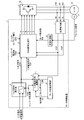
- FIG. 1 is a block diagram illustrating a configuration example of the motor control device according to the first embodiment.
- FIG. 2 is a diagram for explaining the relationship between motor constants and dq axis currents.
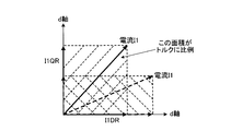
- FIG. 3 is a diagram for explaining the relationship between dq axis currents and torque.
- FIG. 4 is a block diagram illustrating a configuration example of the secondary magnetic flux command calculation unit according to the first embodiment.
- FIG. 5 is a diagram showing a loss curve with respect to the secondary magnetic flux command.
- FIG. 1 is a block diagram illustrating a configuration example of the motor control device according to the first embodiment.
- the motor control device 1 according to the first embodiment is controlled by a vector control method in which a current (primary current) flowing into and out of a motor 12 driven by an inverter 11 is divided into a torque current and an excitation current, and each is controlled individually.
- a torque command calculation unit 4 a secondary magnetic flux command calculation unit 5, a motor constant calculation unit 6, a coordinate conversion unit 7, a speed control unit 8, and a PWM that generates a PWM signal as a voltage command
- a signal generation unit 9 is provided.
- the motor control device 1 includes a notch command and an applied load signal output from an external control device (not shown), and a current detector 14 (14U, 14V, 14W) provided between the inverter 11 and the motor (motor) 12.
- a current detector 14 14U, 14V, 14W
- the motor control device 1 controls the PWM signal as a voltage command for controlling the inverter 11 by the PWM signal generator 9 located at the final stage. (U, V, W, X, Y, Z) is generated.
- the torque command calculation unit 4 receives a notch command and a variable load signal, and an internally generated inverter frequency FINV.
- the torque command calculation unit 4 has a torque command pattern (torque pattern) that keeps the torque constant when the speed is below the threshold value and decreases the torque when the speed exceeds the threshold value.
- a torque command PTR corresponding to the frequency FINV is generated and output to the secondary magnetic flux command calculation unit 5 and the PWM signal generation unit 9.
- the inverter frequency FINV may be an external input signal.
- the motor constant calculation unit 6 calculates a motor constant when the motor 12 is represented by an equivalent circuit model.
- Typical motor constants include primary resistance, secondary resistance, primary inductance, secondary inductance, mutual inductance, number of pole pairs, etc., but in Embodiment 1, at least the secondary inductance L2R and the number of pole pairs Pm The value is output to the secondary magnetic flux command calculation unit 5.
- the number of pole pairs is Pm
- the number of pole pairs Pm output to the secondary magnetic flux command calculation unit 5 is a fixed value.
- a value corresponding to the change is output to the secondary magnetic flux command calculation unit 5.
- Each phase motor current IU, IV, IW detected by the current detector 14 (14U, 14V, 14W) is input to the coordinate conversion unit 7.
- the coordinate conversion unit 7 generates a d-axis current I1DF and a q-axis current I1QF obtained by converting each phase motor current IU, IV, IW, which is a current detection value of the three-phase coordinate system, into a current detection value of the dq-axis coordinate system.
- the d-axis current I1DF is input to both the PWM signal generation unit 9 and the secondary magnetic flux command calculation unit 5, and the q-axis current I1QF is input to the PWM signal generation unit 9.
- phase motor currents IU, IV, IW are input to the coordinate conversion unit 7, but if there is information on any one of the phase motor currents IU, IV, IW,
- the d-axis current I1DF and the q-axis current I1QF can be calculated.
- the inverter frequency FINV, the torque command PTR, the secondary inductance L2R, the pole pair number Pm, and the d-axis current I1DF are input to the secondary magnetic flux command calculation unit 5.
- the secondary magnetic flux command calculation unit 5 generates a secondary magnetic flux command F2R based on the inverter frequency FINV, torque command PTR, secondary inductance L2R, pole pair number Pm, and d-axis current I1DF, and outputs it to the PWM signal generation unit 9 To do.
- the internal configuration and further detailed operation of the secondary magnetic flux command calculation unit 5 will be described later.
- the speed control unit 8 generates a motor frequency FM that is a rotation frequency of the motor 12 based on information such as the cycle of the PG pulse signal and the number of pulses per cycle included in the PG pulse signal, and sends it to the PWM signal generation unit 9. Output.
- the torque signal PTR, the secondary magnetic flux command F2R, the d-axis current I1DF, the q-axis current I1QF, and the motor frequency FM are input to the PWM signal generation unit 9.
- the PWM signal generation unit 9 also receives the inverter frequency FINV and the filter capacitor voltage EFC, which is the voltage of a filter capacitor (not shown) provided on the DC unit side of the inverter 11.
- the PWM signal generator 9 internally generates a torque current command for outputting the torque command PTR and an excitation current command for outputting the secondary magnetic flux command F2R, and a q-axis current I1QF that is a detected value of the torque current.
- U, V, W, X, Y, and Z are generated and output to the inverter 11.
- the PWM signals U, V, W, X, Y, and Z are examples when the inverter 11 is a three-phase inverter, and the switching signals for the switching elements constituting the upper arm correspond to U, V, and W.
- the switching signals for the switching elements constituting the lower arm correspond to X, Y, and Z.
- FIG. 2 is a diagram for explaining the relationship between motor constants and dq axis currents
- FIG. 3 is a diagram for explaining the relationship between dq axis currents and torque in the dq plane.
- the torque current command I1QR and the excitation current command I1DR that are generally used in a control device that performs vector control include a torque command PTR, a secondary inductance L2R, a secondary magnetic flux command F2R, Using the number of pole pairs Pm, the mutual inductance MR, and the secondary resistance R2R, it can be expressed as the following equation and the following equation.
- I1QR (PTR / F2R) ⁇ (1 / Pm) ⁇ (L2R / MR) (1)
- I1DR (F2R / MR) + (L2R / MR) ⁇ (1 / R2R) ⁇ d (F2R) / dt (2)
- the torque command PTR is controlled to a substantially constant value. Therefore, the second term of the equation (2) representing the time change of the secondary magnetic flux command F2R can be set to zero, and the secondary magnetic flux command F2R can be represented by the following equation using the excitation current command I1DR.
- the motor control device of the first embodiment uses the above concept.
- the excitation current command I1DR can be expressed as the following expression using the torque command PTR.
- I1DR ⁇ ⁇ (Pm / L2R) ⁇ PTR ⁇ / MR (5)
- the secondary magnetic flux command F2R can be obtained from the torque command PTR, the secondary inductance L2R, and the number of pole pairs Pm. Therefore, the secondary magnetic flux command calculation unit 5 shown in FIG. 1 is configured as shown in FIG. FIG. 4 is a block diagram illustrating a configuration example of the secondary magnetic flux command calculation unit 5 according to the first embodiment. As illustrated, the secondary magnetic flux command calculation unit 5 includes a minimum current secondary magnetic flux command calculation unit 21 as a first calculation unit, a magnetic flux command compensation calculation unit 22 as a second calculation unit, a multiplier 23, and a subtraction. A device 24 is provided.
- the torque command PTR, the secondary inductance L2R, and the pole pair number Pm are input to the minimum current secondary magnetic flux command calculation unit 21.
- the minimum current secondary magnetic flux command calculation unit 21 Based on the torque command PTR, the secondary inductance L2R, and the pole pair number Pm, the minimum current secondary magnetic flux command calculation unit 21 performs a calculation process shown in the equation (6) and outputs the calculation result as the minimum current secondary magnetic flux command F2R1. To do.
- the current required for the current can be minimized.
- the copper loss in the motor 12 depends on the magnitude of the current, and the loss increases as the current increases. Therefore, the copper loss decreases as the current is reduced.
- the loss in the switching element 16 of the inverter 11 also depends on the magnitude of the current, the loss in the inverter 11 can be reduced by the control that minimizes the current.
- FIG. 5 is a diagram showing a loss curve with respect to the secondary magnetic flux command F2R.
- the solid line represents the copper loss
- the broken line represents the iron loss. Since the loss generated in the motor is dominated by the copper loss and the iron loss, if the sum of the copper loss and the iron loss can be minimized, the motor loss can be substantially minimized.
- the minimum current secondary magnetic flux command value F2R1 at which the copper loss is minimized is not a magnetic flux condition with the minimum loss in consideration of the iron loss.
- the inverter frequency FINV increases and the voltage V applied to the motor increases, the iron loss cannot be ignored.
- the secondary magnetic flux command value F2R is slightly decreased from the minimum current secondary magnetic flux command value F2R1, the decrease in iron loss is larger than the increase in copper loss. The total loss of copper loss and iron loss will also decrease. That is, the secondary magnetic flux command value F2R that minimizes the total loss of copper loss and iron loss is smaller than F2R1. Therefore, in the secondary magnetic flux command calculation unit 5 of the first embodiment, the minimum current secondary of the secondary magnetic flux command value that minimizes the total loss of the copper loss and the iron loss of the motor based on the motor frequency as shown in the figure.
- a magnetic flux command compensation calculation unit 22 for obtaining a compensation amount from the magnetic flux command F2R1 is provided, and the multiplier 23 multiplies the output of the magnetic flux command compensation calculation unit 22 by the d-axis current I1DF, and the multiplication value is obtained as a minimum current. Subtraction is performed from the output of the secondary magnetic flux command calculation unit 21.
- the magnetic flux command compensation calculation unit 22 is provided with an iron loss consideration table for calculating the iron loss based on the motor characteristics at the time of design in advance. Based on the input inverter frequency FINV, the loss due to the iron loss with respect to the d-axis current I1DF. Is generated and output to the multiplier 23.
- the final secondary magnetic flux command F2R is obtained by subtracting the compensation amount considering the iron loss as the output of the multiplier 23 from the minimum current secondary magnetic flux command F2R1. Is generated and output to the PWM signal generator 9.
- the minimum current secondary magnetic flux command F2R1 generated by the minimum current secondary magnetic flux command calculation unit 21 is directly output to the PWM signal generation unit 9 as the secondary magnetic flux command F2R.
- the current effective value due to the torque current and the excitation current in the drive region where the voltage / frequency ratio is constant and the torque is constant is minimized.
- the detected value of the torque current and the detected value of the exciting current match the torque current command for outputting the torque command and the exciting current command for outputting the secondary magnetic flux command, respectively. Since the vector control is performed, the motor loss including the copper loss and the iron loss can be reduced, and a motor control device that enables more efficient operation control can be realized.
- FIG. 1 the switching element 16 provided in the inverter 11 will be described.
- the switching element 16 used in the inverter 11 is generally a semiconductor switching element made of silicon (Si) (IGBT, MOSFET, etc., hereinafter abbreviated as “Si-SW”).
- Si-SW semiconductor switching element made of silicon
- the technique described in the first embodiment can be configured using this general Si-SW.
- the technique of the first embodiment is not limited to this Si-SW.
- SiC-SW semiconductor switching element made of silicon carbide (SiC), which has been attracting attention in recent years, can be used as the switching element 16 described above.
- the loss in the inverter 11 is mainly the switching loss and conduction loss of the switching element 16.
- the SiC-SW has a MOSFET structure, it is expected that the switching loss can be greatly reduced.
- the conduction loss of the MOSFET increases in proportion to the square of the current. Therefore, the conduction loss can be reduced by reducing the value of the current flowing through the SiC-SW. .
- the current for generating the same torque can be minimized, so that the switching element 16 provided in the inverter 11 of the first embodiment is made of SiC-SW.
- the conduction loss can be greatly reduced. Thereby, the loss in the inverter 11 can be reduced, and a motor control device that enables more efficient motor control can be realized.
- the output frequency of the inverter 11 has been controlled by sequentially switching a plurality of control modes of a multi-pulse mode and a single-pulse mode.
- the switching element 16 made of a band gap semiconductor, asynchronous PWM control is possible in the entire control region. Therefore, the loss reduction effect by the motor control device of the present embodiment can be achieved over the entire area, and highly efficient motor control can be performed in the entire area. In particular, the loss reduction effect on the motor is very large when the current value is set high in order to achieve the full-range asynchronous PWM control.
- SiC is an example of a semiconductor referred to as a wide bandgap semiconductor by capturing the characteristic that the bandgap is larger than that of Si (in contrast, Si is referred to as a narrow bandgap semiconductor).
- a semiconductor formed using a gallium nitride-based material or diamond belongs to a wide band gap semiconductor, and their characteristics are also similar to silicon carbide. Therefore, a configuration using a wide band gap semiconductor other than silicon carbide also forms the gist of the present invention.
- the switching element formed of such a wide band gap semiconductor has high voltage resistance and high allowable current density, the switching element can be miniaturized, and these miniaturized switching elements should be used. Thus, it is possible to reduce the size of a semiconductor module incorporating these elements.
- the switching element formed of a wide band gap semiconductor has high heat resistance, in the case of a switching element that requires a cooling mechanism such as a heat sink, the cooling mechanism can be downsized, and the switching element module can be further reduced in size. Can be realized.
- the configurations shown in the first and second embodiments are examples of the configuration of the present invention, and can be combined with other known techniques, and can be combined within a range not departing from the gist of the present invention. Needless to say, the configuration may be modified by omitting the unit.
- the present invention is useful as a motor control device that can reduce motor loss in a low speed region or a light load drive region.
Landscapes
- Engineering & Computer Science (AREA)
- Power Engineering (AREA)
- Control Of Ac Motors In General (AREA)
Abstract
Description
図1は、実施の形態1に係るモータ制御装置の一構成例を示すブロック図である。実施の形態1に係るモータ制御装置1は、インバータ11によって駆動されるモータ12に流出入する電流(1次電流)をトルク電流と励磁電流に分けてそれぞれを個別に制御するベクトル制御方式による制御装置であり、図示のように、トルク指令演算部4、二次磁束指令演算部5、モータ定数演算部6、座標変換部7、速度制御部8および、電圧指令としてのPWM信号を生成するPWM信号生成部9を備えて構成される。
FIG. 1 is a block diagram illustrating a configuration example of the motor control device according to the first embodiment. The
I1DR=(F2R/MR)+(L2R/MR)
×(1/R2R)×d(F2R)/dt …(2) I1QR = (PTR / F2R) × (1 / Pm) × (L2R / MR) (1)
I1DR = (F2R / MR) + (L2R / MR)
× (1 / R2R) × d (F2R) / dt (2)
実施の形態2では、インバータ11に具備されるスイッチング素子16について説明する。インバータ11に用いられるスイッチング素子16としては、珪素(Si)を素材とする半導体スイッチング素子(IGBT、MOSFETなど、以下「Si-SW」と略記)が一般的である。上記実施の形態1で説明した技術は、この一般的なSi-SWを用いて構成することができる。 Embodiment 2. FIG.
In the second embodiment, the switching
Claims (5)
- インバータによって駆動されるモータに流出入する電流をトルク電流と励磁電流に分けてそれぞれを個別に制御するモータ制御装置であって、
トルク電流と励磁電流とによる電流実効値を最小とする最小電流二次磁束指令を演算する第1の演算部を有する二次磁束指令演算部と、
トルク指令を出力するためのトルク電流指令および前記二次磁束指令を出力するための励磁電流指令を生成し、前記トルク電流の検出値および前記励磁電流の検出値がそれぞれ前記トルク電流指令および前記励磁電流指令に一致するようにベクトル制御を行い、前記インバータに具備されるスイッチング素子をオン/オフさせる制御信号を生成するPWM信号生成部と、
を備えたことを特徴とするモータ制御装置。 A motor control device that individually controls the current flowing into and out of the motor driven by the inverter into a torque current and an excitation current,
A secondary magnetic flux command computation unit having a first computation unit that computes a minimum current secondary magnetic flux command that minimizes the current effective value of the torque current and the excitation current;
A torque current command for outputting a torque command and an excitation current command for outputting the secondary magnetic flux command are generated, and the detected value of the torque current and the detected value of the excitation current are the torque current command and the excitation current, respectively. A PWM signal generating unit that performs vector control to match a current command and generates a control signal for turning on / off a switching element included in the inverter;
A motor control device comprising: - 前記第1の演算部は、前記モータの二次インダクタンスおよび極対数ならびに前記トルク指令に基づいて最小電流二次磁束指令を演算することを特徴とする請求項1に記載のモータ制御装置。 The motor control device according to claim 1, wherein the first calculation unit calculates a minimum current secondary magnetic flux command based on the secondary inductance and the number of pole pairs of the motor and the torque command.
- 前記二次磁束指令演算部は、前記モータの周波数に基づいて前記モータの銅損と鉄損の合計損失が最小となる二次磁束指令値の前記最小電流二次磁束指令からの補償分を求める第2の演算部を有してなることを特徴とする請求項2に記載のモータ制御装置。 The secondary magnetic flux command calculation unit obtains a compensation amount from the minimum current secondary magnetic flux command for the secondary magnetic flux command value that minimizes the total loss of the copper loss and iron loss of the motor based on the frequency of the motor. The motor control device according to claim 2, further comprising a second calculation unit.
- 前記スイッチング素子は、ワイドバンドギャップ半導体にて形成されることを特徴とする請求項1~3の何れか1項に記載のモータ制御装置。 The motor control device according to any one of claims 1 to 3, wherein the switching element is formed of a wide band gap semiconductor.
- 前記ワイドバンドギャップ半導体は、炭化ケイ素、窒化ガリウム系材料または、ダイヤモンドを用いた半導体であることを特徴とする請求項4に記載のモータ制御装置。 The motor control device according to claim 4, wherein the wide band gap semiconductor is a semiconductor using silicon carbide, a gallium nitride-based material, or diamond.
Priority Applications (5)
| Application Number | Priority Date | Filing Date | Title |
|---|---|---|---|
| CN201380007352.3A CN104081653B (en) | 2012-01-30 | 2013-01-30 | Motor control device |
| US14/374,242 US9667187B2 (en) | 2012-01-30 | 2013-01-30 | Motor control apparatus |
| JP2013556462A JP5586798B2 (en) | 2012-01-30 | 2013-01-30 | Motor control device |
| EP13743139.1A EP2811644B1 (en) | 2012-01-30 | 2013-01-30 | Motor control device |
| BR112014017549A BR112014017549A2 (en) | 2012-01-30 | 2013-01-30 | motor control apparatus |
Applications Claiming Priority (2)
| Application Number | Priority Date | Filing Date | Title |
|---|---|---|---|
| JP2012-017212 | 2012-01-30 | ||
| JP2012017212 | 2012-01-30 |
Publications (1)
| Publication Number | Publication Date |
|---|---|
| WO2013115240A1 true WO2013115240A1 (en) | 2013-08-08 |
Family
ID=48905272
Family Applications (1)
| Application Number | Title | Priority Date | Filing Date |
|---|---|---|---|
| PCT/JP2013/052026 WO2013115240A1 (en) | 2012-01-30 | 2013-01-30 | Motor control device |
Country Status (6)
| Country | Link |
|---|---|
| US (1) | US9667187B2 (en) |
| EP (1) | EP2811644B1 (en) |
| JP (1) | JP5586798B2 (en) |
| CN (1) | CN104081653B (en) |
| BR (1) | BR112014017549A2 (en) |
| WO (1) | WO2013115240A1 (en) |
Cited By (4)
| Publication number | Priority date | Publication date | Assignee | Title |
|---|---|---|---|---|
| WO2020261751A1 (en) * | 2019-06-25 | 2020-12-30 | 株式会社日立産機システム | Power conversion device |
| US11008014B2 (en) * | 2018-08-14 | 2021-05-18 | Ford Global Technologies, Llc | Methods and apparatus to determine vehicle weight information based on ride height |
| US11072323B2 (en) * | 2018-02-26 | 2021-07-27 | Audi Ag | Method for operating an onboard network of a hybrid motor vehicle and hybrid motor vehicle |
| CN118337108A (en) * | 2024-06-15 | 2024-07-12 | 山东奥卓电气科技发展有限公司 | Vector frequency converter control system |
Families Citing this family (4)
| Publication number | Priority date | Publication date | Assignee | Title |
|---|---|---|---|---|
| CN104852655B (en) * | 2015-04-08 | 2017-08-01 | 华中科技大学 | A kind of Control of Induction Motors method based on vector controlled |
| KR20180109351A (en) * | 2017-03-28 | 2018-10-08 | 엘에스산전 주식회사 | Proportional and resonant current controller |
| EP3462600A1 (en) * | 2017-09-29 | 2019-04-03 | Siemens Aktiengesellschaft | Energy efficient asynchronous machine |
| JP6939693B2 (en) * | 2018-04-27 | 2021-09-22 | 株式会社豊田自動織機 | Pulse pattern generator |
Citations (5)
| Publication number | Priority date | Publication date | Assignee | Title |
|---|---|---|---|---|
| JPH03218291A (en) * | 1990-01-24 | 1991-09-25 | Mitsubishi Electric Corp | Controller for induction motor |
| JPH09191700A (en) | 1996-11-11 | 1997-07-22 | Hitachi Ltd | Method for controlling induction motor |
| JPH09262000A (en) * | 1996-03-26 | 1997-10-03 | Mitsubishi Electric Corp | Control equipment of induction motor |
| JP2006094646A (en) * | 2004-09-24 | 2006-04-06 | Mitsubishi Electric Corp | Vector control device of induction motor |
| JP2011091992A (en) * | 2009-09-28 | 2011-05-06 | Daikin Industries Ltd | Phase current detector and power converter using the same |
Family Cites Families (11)
| Publication number | Priority date | Publication date | Assignee | Title |
|---|---|---|---|---|
| JPS61189193A (en) | 1985-02-15 | 1986-08-22 | Yaskawa Electric Mfg Co Ltd | Induction motor drive controller |
| JP2585376B2 (en) | 1987-06-12 | 1997-02-26 | 株式会社日立製作所 | Control method of induction motor |
| JPH0669307B2 (en) | 1987-09-21 | 1994-08-31 | 富士電機株式会社 | Induction motor control method |
| JP2778753B2 (en) | 1989-09-01 | 1998-07-23 | 株式会社東芝 | Vector controller for induction motor |
| JPH0687596A (en) | 1991-04-15 | 1994-03-29 | Ain Tec:Kk | Winding device for double sheave drum |
| CN1161933A (en) * | 1996-01-27 | 1997-10-15 | Lg产电株式会社 | Device for regulating stop-level of elevator |
| US5949210A (en) * | 1998-03-16 | 1999-09-07 | Lockheed Martin Corp. | Two-dimensional variable limit proportional internal regulator for the current controller in synchronous frame |
| WO2008004294A1 (en) | 2006-07-06 | 2008-01-10 | Mitsubishi Electric Corporation | Induction motor vector control device, induction motor vector control method, and induction motor drive control device |
| EP2048772B1 (en) | 2006-07-24 | 2021-10-20 | Kabushiki Kaisha Toshiba | Variable magnetic flux motor drive system |
| CN101622782B (en) * | 2007-03-08 | 2011-11-16 | 三菱电机株式会社 | Controller of electric vehicle |
| WO2011111175A1 (en) * | 2010-03-09 | 2011-09-15 | 三菱電機株式会社 | Power semiconductor module, power conversion device, and railway vehicles |
-
2013
- 2013-01-30 CN CN201380007352.3A patent/CN104081653B/en active Active
- 2013-01-30 WO PCT/JP2013/052026 patent/WO2013115240A1/en active Application Filing
- 2013-01-30 US US14/374,242 patent/US9667187B2/en active Active
- 2013-01-30 BR BR112014017549A patent/BR112014017549A2/en not_active IP Right Cessation
- 2013-01-30 EP EP13743139.1A patent/EP2811644B1/en active Active
- 2013-01-30 JP JP2013556462A patent/JP5586798B2/en active Active
Patent Citations (5)
| Publication number | Priority date | Publication date | Assignee | Title |
|---|---|---|---|---|
| JPH03218291A (en) * | 1990-01-24 | 1991-09-25 | Mitsubishi Electric Corp | Controller for induction motor |
| JPH09262000A (en) * | 1996-03-26 | 1997-10-03 | Mitsubishi Electric Corp | Control equipment of induction motor |
| JPH09191700A (en) | 1996-11-11 | 1997-07-22 | Hitachi Ltd | Method for controlling induction motor |
| JP2006094646A (en) * | 2004-09-24 | 2006-04-06 | Mitsubishi Electric Corp | Vector control device of induction motor |
| JP2011091992A (en) * | 2009-09-28 | 2011-05-06 | Daikin Industries Ltd | Phase current detector and power converter using the same |
Cited By (9)
| Publication number | Priority date | Publication date | Assignee | Title |
|---|---|---|---|---|
| US11072323B2 (en) * | 2018-02-26 | 2021-07-27 | Audi Ag | Method for operating an onboard network of a hybrid motor vehicle and hybrid motor vehicle |
| US11008014B2 (en) * | 2018-08-14 | 2021-05-18 | Ford Global Technologies, Llc | Methods and apparatus to determine vehicle weight information based on ride height |
| WO2020261751A1 (en) * | 2019-06-25 | 2020-12-30 | 株式会社日立産機システム | Power conversion device |
| JP2021005922A (en) * | 2019-06-25 | 2021-01-14 | 株式会社日立産機システム | Power conversion device |
| CN113302832A (en) * | 2019-06-25 | 2021-08-24 | 株式会社日立产机系统 | Power conversion device |
| US11575338B2 (en) | 2019-06-25 | 2023-02-07 | Hitachi Industrial Equipment Systems Co., Ltd. | Power conversion device |
| CN113302832B (en) * | 2019-06-25 | 2023-09-12 | 株式会社日立产机系统 | power conversion device |
| JP7479128B2 (en) | 2019-06-25 | 2024-05-08 | 株式会社日立産機システム | Power Conversion Equipment |
| CN118337108A (en) * | 2024-06-15 | 2024-07-12 | 山东奥卓电气科技发展有限公司 | Vector frequency converter control system |
Also Published As
| Publication number | Publication date |
|---|---|
| EP2811644A4 (en) | 2016-01-20 |
| JP5586798B2 (en) | 2014-09-10 |
| EP2811644A1 (en) | 2014-12-10 |
| JPWO2013115240A1 (en) | 2015-05-11 |
| US20150028793A1 (en) | 2015-01-29 |
| EP2811644B1 (en) | 2019-05-22 |
| BR112014017549A2 (en) | 2017-07-04 |
| CN104081653A (en) | 2014-10-01 |
| CN104081653B (en) | 2017-03-22 |
| US9667187B2 (en) | 2017-05-30 |
Similar Documents
| Publication | Publication Date | Title |
|---|---|---|
| JP5586798B2 (en) | Motor control device | |
| JP5133834B2 (en) | AC motor control device | |
| JP3627683B2 (en) | Motor control device | |
| JP5031128B1 (en) | Electric motor control device and control method, electric motor and vehicle drive system to which the same is applied | |
| JP4489098B2 (en) | Power generation control device | |
| US9246428B2 (en) | Vector control device for an electric motor that controls an electric power converter that converts DC power to AC power, electric motor, vehicle drive system, and vector control method for electric motor | |
| JP5084973B1 (en) | Motor control device | |
| JP2012016259A (en) | Power converter control system | |
| US9641119B2 (en) | Extended-speed low-ripple torque control of switched reluctance motor drives | |
| JP2010246207A (en) | Controller for alternating-current motor | |
| TW200924366A (en) | Matrix converter | |
| JP6080996B1 (en) | Electric motor drive system | |
| JP5281370B2 (en) | AC motor control device | |
| CN113302832A (en) | Power conversion device | |
| Hsieh et al. | System response of permanent magnet synchronous motor drive based on SiC power transistor | |
| WO2013132660A1 (en) | Motor control device | |
| JP5277846B2 (en) | AC motor control system | |
| JP5836413B2 (en) | Vector control device for electric motor and vehicle drive system | |
| WO2024053177A1 (en) | Motor control device | |
| Babaei et al. | Torque ripple minimization with optimized i sx estimation in vector control of current source inverter induction motor | |
| JP2008263670A (en) | Driving device of motor |
Legal Events
| Date | Code | Title | Description |
|---|---|---|---|
| 121 | Ep: the epo has been informed by wipo that ep was designated in this application |
Ref document number: 13743139 Country of ref document: EP Kind code of ref document: A1 |
|
| ENP | Entry into the national phase |
Ref document number: 2013556462 Country of ref document: JP Kind code of ref document: A |
|
| WWE | Wipo information: entry into national phase |
Ref document number: 14374242 Country of ref document: US Ref document number: 2013743139 Country of ref document: EP |
|
| NENP | Non-entry into the national phase |
Ref country code: DE |
|
| REG | Reference to national code |
Ref country code: BR Ref legal event code: B01A Ref document number: 112014017549 Country of ref document: BR |
|
| ENP | Entry into the national phase |
Ref document number: 112014017549 Country of ref document: BR Kind code of ref document: A2 Effective date: 20140716 |