WO2013111422A1 - 無線通信装置及び無線通信方法、並びに無線通信システム - Google Patents
無線通信装置及び無線通信方法、並びに無線通信システム Download PDFInfo
- Publication number
- WO2013111422A1 WO2013111422A1 PCT/JP2012/079192 JP2012079192W WO2013111422A1 WO 2013111422 A1 WO2013111422 A1 WO 2013111422A1 JP 2012079192 W JP2012079192 W JP 2012079192W WO 2013111422 A1 WO2013111422 A1 WO 2013111422A1
- Authority
- WO
- WIPO (PCT)
- Prior art keywords
- reference signal
- measurement
- base station
- frequency
- wireless communication
- Prior art date
Links
Images


Classifications
-
- H—ELECTRICITY
- H04—ELECTRIC COMMUNICATION TECHNIQUE
- H04L—TRANSMISSION OF DIGITAL INFORMATION, e.g. TELEGRAPHIC COMMUNICATION
- H04L5/00—Arrangements affording multiple use of the transmission path
- H04L5/003—Arrangements for allocating sub-channels of the transmission path
- H04L5/0032—Distributed allocation, i.e. involving a plurality of allocating devices, each making partial allocation
- H04L5/0035—Resource allocation in a cooperative multipoint environment
-
- H—ELECTRICITY
- H04—ELECTRIC COMMUNICATION TECHNIQUE
- H04L—TRANSMISSION OF DIGITAL INFORMATION, e.g. TELEGRAPHIC COMMUNICATION
- H04L5/00—Arrangements affording multiple use of the transmission path
- H04L5/0001—Arrangements for dividing the transmission path
- H04L5/0003—Two-dimensional division
- H04L5/0005—Time-frequency
- H04L5/0007—Time-frequency the frequencies being orthogonal, e.g. OFDM(A), DMT
- H04L5/001—Time-frequency the frequencies being orthogonal, e.g. OFDM(A), DMT the frequencies being arranged in component carriers
-
- H—ELECTRICITY
- H04—ELECTRIC COMMUNICATION TECHNIQUE
- H04W—WIRELESS COMMUNICATION NETWORKS
- H04W24/00—Supervisory, monitoring or testing arrangements
- H04W24/02—Arrangements for optimising operational condition
-
- H—ELECTRICITY
- H04—ELECTRIC COMMUNICATION TECHNIQUE
- H04W—WIRELESS COMMUNICATION NETWORKS
- H04W48/00—Access restriction; Network selection; Access point selection
- H04W48/18—Selecting a network or a communication service
-
- H—ELECTRICITY
- H04—ELECTRIC COMMUNICATION TECHNIQUE
- H04B—TRANSMISSION
- H04B7/00—Radio transmission systems, i.e. using radiation field
- H04B7/02—Diversity systems; Multi-antenna system, i.e. transmission or reception using multiple antennas
- H04B7/022—Site diversity; Macro-diversity
- H04B7/024—Co-operative use of antennas of several sites, e.g. in co-ordinated multipoint or co-operative multiple-input multiple-output [MIMO] systems
-
- H—ELECTRICITY
- H04—ELECTRIC COMMUNICATION TECHNIQUE
- H04L—TRANSMISSION OF DIGITAL INFORMATION, e.g. TELEGRAPHIC COMMUNICATION
- H04L5/00—Arrangements affording multiple use of the transmission path
- H04L5/003—Arrangements for allocating sub-channels of the transmission path
- H04L5/0048—Allocation of pilot signals, i.e. of signals known to the receiver
- H04L5/005—Allocation of pilot signals, i.e. of signals known to the receiver of common pilots, i.e. pilots destined for multiple users or terminals
-
- H—ELECTRICITY
- H04—ELECTRIC COMMUNICATION TECHNIQUE
- H04L—TRANSMISSION OF DIGITAL INFORMATION, e.g. TELEGRAPHIC COMMUNICATION
- H04L5/00—Arrangements affording multiple use of the transmission path
- H04L5/003—Arrangements for allocating sub-channels of the transmission path
- H04L5/0053—Allocation of signaling, i.e. of overhead other than pilot signals
- H04L5/0057—Physical resource allocation for CQI
-
- H—ELECTRICITY
- H04—ELECTRIC COMMUNICATION TECHNIQUE
- H04L—TRANSMISSION OF DIGITAL INFORMATION, e.g. TELEGRAPHIC COMMUNICATION
- H04L5/00—Arrangements affording multiple use of the transmission path
- H04L5/003—Arrangements for allocating sub-channels of the transmission path
- H04L5/0078—Timing of allocation
-
- H—ELECTRICITY
- H04—ELECTRIC COMMUNICATION TECHNIQUE
- H04W—WIRELESS COMMUNICATION NETWORKS
- H04W16/00—Network planning, e.g. coverage or traffic planning tools; Network deployment, e.g. resource partitioning or cells structures
- H04W16/24—Cell structures
- H04W16/32—Hierarchical cell structures
Definitions
- the technology disclosed in the present specification relates to a wireless communication apparatus and a wireless communication method that transmit and receive data simultaneously to a terminal in cooperation with another base station, and a wireless communication system, in particular, from a terminal that has received a reference signal.
- the present invention relates to a wireless communication apparatus, a wireless communication method, and a wireless communication system that determine a combination of base stations with respect to a terminal based on feedback of the communication.
- LTE Long Term Evolution
- 4G 4th generation
- 4G 4th generation
- FDD Frequency Division Duplex
- TDD Time Division Duplex
- an uplink-dedicated band and a downlink-dedicated band are used.
- the uplink and downlink use a radio frame format composed of 10 consecutive subframes.
- the uplink here refers to communication from a terminal station (UE terminal: User Equipment) to an LTE base station (eNodeB: evolved Node B), and the downlink refers to communication from the eNodeB to the UE terminal. That is.
- eNodeB evolved Node B
- a radio frame format composed of 10 consecutive subframes is used.
- TDD communication is performed using the same band in the uplink and downlink.
- Each subframe configuring the radio frame includes a control signal PDCCH (Phy Downlink Control Channel) from the eNodeB and a PDSCH (Phy Downlink Shared Channel) used as user data.
- PDCCH Physical Downlink Control Channel
- PDSCH Physical Downlink Shared Channel
- CoMP Coordinated Multi Point Transmission / Reception
- CoMP is a technique for increasing desired signal power and reducing interference from other cells by simultaneously transmitting and receiving data to and from one UE terminal by a plurality of eNodeBs.
- precoding, reference signals, measurement and feedback methods should be considered.
- LTE in Release 8, a method of hierarchizing cells of various sizes such as Macro / Micro / Pico / Femto called HetNet is considered, but CoMP includes communication to such a femto cell.
- UpLink CoMP and DownLink CoMP exist in CoMP, and UpLink CoMP is an important technology as well as DownLink CoMP, but below, it will be described as DownLink CoMP unless otherwise noted.
- a cell method for realizing CoMP there are a method in which a plurality of eNodeBs each perform autonomous distributed control, and a method in which one Macro eNodeB centrally controls a plurality of Pico eNodeBs.
- a plurality of base stations such as RRH (Remote Radio Head) are arranged for countermeasures against insensitiveness at the cell edge and the like, and an optical fiber is used between Macro eNodeBs that centrally control these base stations. Connected by a baseband signal (described later). Then, the Macro eNodeB performs baseband signal processing and control of each RRH, and collectively performs radio resource control between cells.
- RRH Remote Radio Head
- CoMP is performed on a certain UE terminal, that is, a combination of eNodeBs constituting a cooperative group is hereinafter referred to as Set of CoMP transmission point, or CoMP set for short.
- CoMP set determination it is necessary to determine which eNodeB is effective for the UE terminal. This will be referred to as CoMP set determination or point selection.
- a UE terminal receives a reference signal from each base station, measures RSRP (Reference Signal Received Power) for each base station, and selects an eNodeB located above it as a CoMP set The method of doing is mentioned.
- RSRP Reference Signal Received Power
- the base station transmits the cooperative group setting signaling with the Cell ID of the cell in the cooperative group selected for the user terminal to the user terminal, and the user terminal is attached to the cooperative group setting signaling.
- the base station allocates a part of the entire frequency band to bands used for single base station transmission (first transmission scheme) and multiple base station transmission (second transmission scheme), and receives one of them.
- Decide which transmission method to use based on the feedback information indicating the received quality that is, limit the feedback information to information indicating the received quality of a part of the entire frequency band to reduce the amount of feedback information
- Proposals have been made regarding wireless communication methods (see, for example, Patent Document 2).
- each base station apparatus receives quality information indicating communication quality between the base station apparatus capable of communicating with the target terminal apparatus from the target terminal apparatus and also exists in a cell of another base station apparatus.
- Proposal has been made for a wireless communication system that acquires schedule information indicating a communication schedule to and selects several base station apparatuses that function as base stations for the target terminal apparatus based on quality information and schedule information (for example, , See Patent Document 3).
- the eNodeB necessary for the UE terminal is determined, but it is also important not to use more eNodeB than necessary for CoMP. This is because incorporating more eNodeBs than necessary into the CoMP set will reduce the throughput of the entire system and increase the emission of unnecessary radio waves to the neighborhood. For example, if downlink transmission is performed using eNodeB # 1 and eNodeB # 2 as a CoMP set and sufficient transmission quality is obtained for the UE terminal, eNodeB # 3 is placed in the vicinity by adding eNodeB # 3 to the CoMP set. By emitting unnecessary radio waves, it becomes an interference source. Therefore, it is important to configure the CoMP set with the minimum necessary eNodeB that satisfies the required quality.
- the point selection required for the frequency of point selection needs to be performed at certain intervals (that is, the CoMP set needs to be updated at certain intervals). That is, there is a problem whether the CoMP set of the UE terminal is updated to quasi-static (Semi-Static) or dynamically (Dynamic). Considering the movement of UE terminals, dynamic point selection that dynamically updates the CoMP set is desirable.
- An object of the technology disclosed in the present specification is to provide an excellent radio communication apparatus and radio that can suitably perform dynamic point selection based on feedback from a UE terminal that has received a reference signal by applying CoMP technology.
- a communication method and a wireless communication system are provided.
- a further object of the technology disclosed in the present specification is to provide an excellent wireless communication apparatus and wireless communication method capable of improving the frequency of point selection update while suppressing downlink and uplink overhead caused by a reference signal.
- An object is to provide a wireless communication system.
- a further object of the technology disclosed in the present specification is to provide an excellent radio communication apparatus and radio communication method capable of improving the frequency of point selection update while suppressing power consumption of a UE terminal that measures a reference signal And providing a wireless communication system.
- a measurement control unit that sets the type of reference signal to be measured for determination of a cooperative group that performs multi-point cooperative transmission and reception for its own device;
- a reference signal measuring unit that is transmitted from each base station and measures the type of reference signal set by the measurement control unit for determining the cooperative group; and Is a wireless communication device.
- the measurement control unit of the wireless communication apparatus performs measurement for determination of a cooperative group according to a scenario applied in the current cell.
- the reference signal type is set.
- each base station can be assigned to different locations between base stations having the same cell identifier, and the first reference signal capable of adjusting the transmission cycle;
- the base station having the same cell identifier transmits a second reference signal that uses the same location, and the measurement control unit of the wireless communication device according to claim 2 depends on the same large base station.
- the first reference signal is set for measurement for determining a cooperative group, and even if it is subordinate to the same large base station, it is unique for each base station. Is configured to set the second reference signal for measurement for determining a cooperative group.
- the measurement control unit of the wireless communication apparatus determines the type of the reference signal to be measured for determining the cooperation group based on the notification from the base station. Is configured to set.
- each base station can be assigned to different locations between base stations having the same cell identifier, and the first reference signal capable of adjusting the transmission period;
- the base station having the same cell identifier is configured to transmit a second reference signal that uses the same location, and the measurement control unit of the wireless communication device according to claim 4 is configured to specify the specific information notified from the base station.
- the first reference signal is set for the measurement for determining the cooperative group for the base stations having the cell identifiers
- the second reference signal is set for the base station having the other cell identifiers for the cooperative group. It is configured to set for measurement for determination.
- a first reference signal that can be assigned to different locations between base stations having the same cell identifier and whose transmission cycle can be adjusted, and a second that uses the same location between base stations having the same cell identifier
- a reference signal transmitter for transmitting a reference signal of
- a notification unit that notifies a terminal belonging to the own device of a cell identifier to be measured for determination of a cooperative group using the first reference signal; Is a wireless communication device.
- the notification unit of the wireless communication apparatus is configured so that, in a scenario where the same cell identifier is assigned to each base station subordinate to the same large base station, Is configured to notify a cell identifier to be measured for cooperative group determination using the first reference signal.
- the technique described in claim 8 of the present application is: A subordinate base station information acquisition unit for acquiring information of a base station subordinate to the own device; Based on the information of the base station acquired by the dependent base station information acquisition unit, a transmission frequency control unit that controls the frequency of transmitting a reference signal for determining a coordination group that performs multi-point coordinated transmission / reception, A notification unit for notifying each base station of control information by the transmission frequency control unit; Is a wireless communication device.
- the subordinate base station information acquisition unit of the radio communication device transmits a terminal that requires multipoint coordinated transmission / reception from a base station subordinate to the own device.
- the information regarding the number of units is acquired, and the transmission frequency control unit is configured to control the frequency of transmitting the reference signal according to the number of terminals that require multipoint coordinated transmission / reception.
- the transmission frequency control unit of the wireless communication apparatus is configured to transmit a reference signal when the number of terminals requiring multipoint coordinated transmission / reception is small. Is configured to lengthen.
- the technique according to claim 11 of the present application is A reference signal transmission unit for transmitting a first reference signal; A feedback information acquisition unit for acquiring feedback of the measurement result of the first reference signal from the terminal; A measurement unit for measuring a reference signal for measuring a second reference signal transmitted from the terminal; Based on the feedback information acquired by the feedback information acquisition unit and the measurement result of the measurement unit, a point selection unit that determines a cooperative group that performs multipoint cooperative transmission and reception for a terminal station, Is a wireless communication device.
- the point selection unit of the wireless communication device includes the feedback information acquired by the feedback information acquisition unit when TDD is applied. Based on the measurement result of the measurement unit, a coordination group that performs multipoint coordinated transmission / reception for the terminal station is determined.
- the technique according to claim 13 of the present application is A reference signal measurement unit that measures a reference signal transmitted from each base station for determining a cooperative group that performs multi-point cooperative transmission and reception for its own device, and A measurement frequency control unit for controlling the frequency of measurement in the reference signal measurement unit based on the moving speed of the device itself; Is a wireless communication device.
- the measurement frequency control unit of the wireless communication device of claim 13 causes the reference signal measurement unit to perform measurement only when the moving speed of the device itself is large. It is configured.
- the technique described in claim 15 of the present application is: A reference signal measurement unit that measures a reference signal transmitted from each base station for determining a cooperative group that performs multi-point cooperative transmission and reception for its own device, and Based on the measurement result in the reference signal measurement unit, a measurement frequency control unit for controlling the measurement frequency for each base station in the reference signal measurement unit, Is a wireless communication device.
- the measurement frequency control unit of the wireless communication device is a base station in which deterioration of communication quality is detected based on a measurement result in the reference signal measurement unit. Is configured to increase the measurement frequency.
- the measurement frequency control unit of the wireless communication device detects a base station whose communication quality has deteriorated in the cooperative group
- the measurement frequency control unit It is configured to increase the measurement frequency for new base stations that are not included.
- the subordinate base station information acquisition unit of the radio communication device acquires the arrangement information of base stations subordinate to the own device, and the transmission frequency control unit The frequency of transmitting the reference signal is controlled according to the density of base stations subordinate to the own apparatus.
- the transmission frequency control unit of the wireless communication device determines the frequency of transmitting the reference signal in an area where the density of base stations subordinate to the device is high. It is configured to be high.
- a base station information acquisition unit that acquires location information of base stations that can be incorporated into a cooperative group that performs multi-point cooperative transmission and reception for its own device; Based on the acquired base station arrangement information, a measurement frequency control unit that controls the frequency of measuring a reference signal from the base station for determining the cooperative group; According to the frequency controlled by the measurement frequency control unit, a reference signal measurement unit that measures a reference signal from a base station, Is a wireless communication device.
- the measurement frequency control unit of the wireless communication device measures the reference signal in an area where the density of base stations that can be incorporated into the cooperative group is high. It is configured to increase the frequency of performing.
- the technology described in claim 22 of the present application is: A carrier determination unit that determines the importance of performing multi-point coordinated transmission / reception for each component / carrier when performing carrier aggregation; Based on the determination result in the carrier determination unit, a transmission frequency control unit that controls the frequency of transmitting a reference signal for determining a cooperation group that performs multipoint coordinated transmission / reception in each component carrier, A notification unit for notifying each base station of control information by the transmission frequency control unit; Is a wireless communication device.
- the transmission frequency control unit of the wireless communication apparatus determines the frequency of transmitting the reference signal by a component carrier having high importance of performing multipoint coordinated transmission / reception. It is configured to be high.
- a transmission frequency control unit that controls the frequency of transmitting a reference signal for determining a cooperation group that performs multipoint coordinated transmission / reception in each component carrier according to the frequency,
- a notification unit for notifying each base station of control information by the transmission frequency control unit; Is a wireless communication device.
- the transmission frequency control unit of the wireless communication device is configured to increase the frequency of transmitting the reference signal by a component carrier having a high frequency. Yes.
- a transmission frequency control unit that controls the frequency of transmitting a reference signal for determining a cooperation group that performs multipoint coordinated transmission / reception in each component carrier according to the frequency arrangement,
- a notification unit for notifying each base station of control information by the transmission frequency control unit; Is a wireless communication device.
- the transmission frequency control unit of the wireless communication apparatus transmits the reference signal only to one of the component carriers arranged consecutively in frequency. It is configured to be
- the transmission frequency control unit of the wireless communication apparatus of claim 26 is overlapped in terms of time and frequency with each component carrier arranged continuously in frequency.
- the reference signal is transmitted so as not to occur.
- the subordinate base station information acquisition unit of the radio communication device of claim 8 is configured so that the number of terminals in a radio link control connection state with each base station subordinate to the own device.
- the transmission frequency control unit is configured to control the frequency at which each base station subordinate to the own device transmits a reference signal according to the number of terminals in the radio link control connection state.
- the transmission frequency control unit of the radio communication apparatus transmits the reference signal from the base station having a large number of terminals in the radio link control connection state. Is configured to be high.
- the technique described in claim 32 of the present application is: A first reference signal that can be assigned to different locations between base stations having the same cell identifier and whose transmission cycle can be adjusted, and a second that uses the same location between base stations having the same cell identifier
- a wireless communication method is:
- the technique described in claim 34 of the present application is: A feedback information acquisition step of acquiring feedback of the measurement result of the first reference signal from the terminal; A measurement step of measuring a reference signal for measuring a second reference signal transmitted from the terminal; Based on the feedback information acquired in the feedback information acquisition step and the measurement result of the measurement step, a point selection step for determining a cooperative group that performs multipoint cooperative transmission / reception for the terminal station, A wireless communication method.
- the technique according to claim 35 of the present application is A measurement frequency control step for controlling the frequency of measuring the reference signal transmitted from each base station based on the moving speed of the own device; In accordance with the frequency controlled in the measurement frequency control step, a reference signal is measured for a coordinated group determination for performing multipoint coordinated transmission / reception for its own device, A wireless communication method.
- a reference signal measurement step for measuring a reference signal transmitted from each base station for determination of a cooperative group that performs multipoint cooperative transmission / reception for the own device; Based on the measurement result in the reference signal measurement step, a measurement frequency control step for controlling the measurement frequency for each base station in the reference signal measurement unit, A wireless communication method.
- a base station information acquisition step for acquiring base station arrangement information that can be incorporated into a cooperative group that performs multi-point cooperative transmission / reception for its own device; Based on the acquired base station arrangement information, a measurement frequency control step for controlling the frequency of measuring the reference signal from the base station for determining the cooperative group; According to the frequency controlled in the measurement frequency control step, a reference signal measurement step for measuring a reference signal from a base station, A wireless communication method.
- the technique described in claim 38 of the present application is A carrier determination step for determining the importance of performing multi-point coordinated transmission / reception for each component / carrier when performing carrier aggregation; Based on the determination result in the carrier determination step, a transmission frequency control step for controlling the frequency of transmitting a reference signal for determining a cooperation group that performs multipoint coordinated transmission / reception in each component carrier, A notification step of notifying each base station of control information by the transmission frequency control step; A wireless communication method.
- a transmission frequency control step for controlling the frequency of transmitting a reference signal for determining a cooperative group that performs multipoint coordinated transmission / reception in each component carrier according to frequency, A notification step of notifying each base station of control information by the transmission frequency control step; A wireless communication method.
- the technique according to claim 40 of the present application is When performing carrier aggregation, a transmission frequency control step for controlling the frequency of transmitting a reference signal for determining a coordination group that performs multipoint coordinated transmission / reception in each component carrier according to the frequency arrangement, A notification step of notifying each base station of control information by the transmission frequency control step; A wireless communication method.
- the technology described in claim 41 of the present application is: A plurality of base stations each transmitting a plurality of types of reference signals; A terminal station that measures the reference signal by setting the type of the reference signal to be measured in order to determine a cooperative group that performs multipoint cooperative transmission / reception for the own station, Is a wireless communication system.
- system here refers to a logical collection of a plurality of devices (or functional modules that realize specific functions), and each device or functional module is in a single housing. It does not matter whether or not (hereinafter the same).
- a first reference signal that can be assigned to different locations between base stations having the same cell identifier and whose transmission cycle can be adjusted, and a second that uses the same location between base stations having the same cell identifier
- a plurality of base stations each transmitting a reference signal of A terminal station that performs a measurement for determining a cooperative group that receives a reference signal and performs multi-point cooperative transmission and reception for the local station; Comprising At least one of the plurality of base stations notifies a cell identifier to be measured for cooperative group determination using a first reference signal to a terminal station belonging to the own station.
- a wireless communication system A wireless communication system.
- a plurality of base stations transmitting reference signals A terminal station that performs measurement for determination of a cooperative group that receives a reference signal from a base station and performs multipoint cooperative transmission and reception for the local station; Comprising At least one of the plurality of base stations controls the frequency at which each base station transmits a reference signal based on information acquired from a base station subordinate to the own station.
- a wireless communication system A wireless communication system.
- the technology described in claim 44 of the present application is: A plurality of base stations transmitting a first reference signal; A terminal station that receives the first reference signal and performs measurement for determining a cooperative group that performs multi-point coordinated transmission / reception for the local station, feeds back to the base station, and transmits the second reference signal; Comprising At least one of the plurality of base stations performs multipoint coordinated transmission / reception for the terminal station based on feedback information from the terminal station and a measurement result of the second reference signal at the local station. Determine the collaborative group, A wireless communication system.
- the technique described in claim 45 of the present application is: A plurality of base stations transmitting reference signals; A terminal station that receives a reference signal at a frequency according to the moving speed of the local station and performs measurement for determining a cooperative group that performs multipoint cooperative transmission and reception for the local station; Is a wireless communication system.
- the technology described in claim 46 of the present application is: A plurality of base stations transmitting reference signals; A terminal station that receives a reference signal from the base station and performs measurement for determining a cooperative group that performs multipoint cooperative transmission and reception for the local station; Comprising The terminal station controls the measurement frequency for each base station based on the measurement result of the reference signal from each base station.
- a wireless communication system A wireless communication system.
- the technology described in claim 47 of the present application is: A plurality of base stations transmitting reference signals; A terminal station that receives a reference signal from the base station and performs measurement for determining a cooperative group that performs multipoint cooperative transmission and reception for the local station; Comprising The terminal station controls the frequency of measuring the reference signal from the base station based on the arrangement information of the base station that can be incorporated into the cooperation group.
- a wireless communication system A wireless communication system.
- the technique described in claim 48 of the present application is: A plurality of base stations transmitting reference signals; A terminal station that receives a reference signal from the base station and performs measurement for determining a cooperative group that performs multipoint cooperative transmission and reception for the local station; Comprising When performing carrier aggregation, at least one of the plurality of base stations determines the frequency of transmitting a reference signal for each component carrier based on the importance of performing multipoint coordinated transmission / reception in each component carrier. Control, A wireless communication system.
- the technique described in claim 49 of the present application is: A plurality of base stations transmitting reference signals; A terminal station that receives a reference signal from the base station and performs measurement for determining a cooperative group that performs multipoint cooperative transmission and reception for the local station; Comprising At least any one of the plurality of base stations controls the frequency of transmitting a reference signal for each component carrier according to the frequency of each component carrier when performing carrier aggregation.
- a wireless communication system is: A plurality of base stations transmitting reference signals; A terminal station that receives a reference signal from the base station and performs measurement for determining a cooperative group that performs multipoint cooperative transmission and reception for the local station; Comprising At least any one of the plurality of base stations controls the frequency of transmitting a reference signal for each component carrier according to the frequency of each component carrier when performing carrier aggregation.
- the technique described in claim 50 of the present application is: A plurality of base stations transmitting reference signals; A terminal station that receives a reference signal from the base station and performs measurement for determining a cooperative group that performs multipoint cooperative transmission and reception for the local station; Comprising When at least one of the plurality of base stations performs carrier aggregation, reference signals are respectively transmitted from component carriers that are continuously arranged in frequency according to the frequency arrangement of each component carrier. Control how often A wireless communication system.
- FIG. 1 is a diagram schematically showing a form in which a Macro eNodeB and a plurality of RRHs subordinate thereto are connected.
- FIG. 2 is a diagram showing a communication sequence example in which point selection is performed using CSI-RS only in scenario 4.
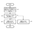
- FIG. 3 is a flowchart showing a processing procedure for controlling the CSI-RS transmission period based on the number of UE terminals that require CoMP.
- FIG. 4 is a diagram illustrating an example of a communication sequence in which measurement for point selection is performed using both SRS and CSI-RS.
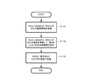
- FIG. 5 is a flowchart illustrating a processing procedure in which the UE terminal feeds back a measurement result to the eNodeB at a measurement cycle corresponding to the moving speed of the own station.
- FIG. 6 is a diagram illustrating an example of a communication sequence in which the eNodeB transmits the CSI-RS at a predetermined transmission cycle, whereas the UE terminal receives the CSI-RS at the measurement cycle set by the UE.
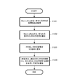
- FIG. 7 is a flowchart illustrating a processing procedure for removing the eNodeB having a large quality degradation from the CoMP set by controlling the measurement frequency of the reference signal.
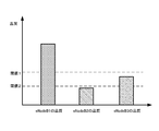
- FIG. 8 is a diagram schematically showing the result of measuring the quality of each eNodeB at the UE terminal.
- FIG. 9 is a flowchart illustrating a processing procedure for searching for an eNodeB to be newly added to the CoMP set by controlling the measurement frequency of the reference signal.
- FIG. 7 is a flowchart illustrating a processing procedure for removing the eNodeB having a large quality degradation from the CoMP set by controlling the measurement frequency of the reference signal.
- FIG. 8 is a diagram schematically showing the result of measuring the quality of each e
- FIG. 10 is a diagram showing an example of the distribution of RRH existing in a cell.
- FIG. 11 is a flowchart showing a processing procedure for controlling the transmission frequency of CSI-RS from the eNodeB according to the density of RRH.
- FIG. 12 is a flowchart illustrating a processing procedure for the UE terminal to control the reception frequency of CSI-RS from the eNodeB according to the density of RRH.
- FIG. 13 is a diagram illustrating an example in which a secondary carrier is used as a component carrier specialized for CoMP when combining carrier aggregation and CoMP technology.
- FIG. 14 is a diagram illustrating an example of controlling the CSI-RS transmission frequency in the component carrier according to the frequency when combining the carrier aggregation and the CoMP technology.
- FIG. 15 is a diagram illustrating an example in which CSI-RS is transmitted only in one of component carrier 1 and component carrier 2 adjacent on the frequency axis.
- FIG. 16 is a diagram illustrating an example in which CSI-RS is transmitted in such a manner that component carrier 1 and component carrier 2 that are adjacent on the frequency axis are divided so as not to overlap on the time axis and the frequency axis.
- FIG. 17 is a flowchart of a processing procedure for controlling the transmission period of the RRH CSI-RS in accordance with the usage status for the CoMP set.
- FIG. 18 is a diagram schematically illustrating a configuration example of a wireless communication device 1800 that operates as a Macro eNodeB.
- FIG. 18 is a diagram schematically illustrating a configuration example of a wireless communication device 1800 that operates as a Macro eNodeB.
- FIG. 19 is a diagram schematically illustrating a configuration example of a wireless communication device 1900 that operates as a Pico eNodeB or RRH.
- FIG. 20 is a diagram schematically illustrating a configuration example of a radio communication apparatus 2000 that operates as a UE terminal.
- FIG. 21 is a diagram illustrating an LTE downlink radio frame configuration.
- FIG. 22 is a diagram illustrating a state in which CRS is inserted in a subframe.
- LTE is a communication system based on the OFDM modulation system, and OFDMA is adopted as a downlink radio access system.
- FIG. 21 illustrates a configuration of an LTE downlink radio frame. As shown in the figure, the radio frame is hierarchized into three layers of a time slot (Slot), a subframe (Subframe), and a radio frame (Radio Frame) in ascending order of time units.
- Slot time slot
- Subframe subframe
- Radio Frame radio frame in ascending order of time units.
- a time slot of 0.5 millisecond length is composed of 7 OFDM symbols (in the case of normal unicast transmission), and is a unit of demodulation processing when receiving on the user (UE terminal) side.
- a subframe having a length of 1 millisecond is composed of two consecutive time slots (14 OFDM symbols), and is a transmission time unit of one data packet subjected to correction coding.
- a radio frame having a length of 10 milliseconds is composed of 10 consecutive subframes (that is, 20 time slots) and is a basic unit for multiplexing all physical channels.
- the subframe is divided into a control area PDCCH used as a control signal from the eNodeB and a data area PDSCH used as user data.
- Each user can communicate without interfering with each other by using different subcarriers or different time slots.
- resource block RB
- the scheduler installed in the base station eNodeB
- the scheduler installed in the base station allocates radio resources to each user in resource block units.
- a maximum of 3 OFDM symbols from the top of the subframe are used for the control channel, that is, PDCCH.
- the scheduler of the base station can perform resource block allocation every subframe, that is, at an interval of 1 millisecond.
- Resource block location information is called scheduling. Both uplink scheduling information and downlink scheduling information are described in the downlink control channel. Each user can see the control channel and see the resource blocks assigned to him.
- a 0.5 mm long time slot is the smallest unit of allocation that can be used by each user.
- the scheduler installed in the base station (eNodeB) allocates time slots that may be used in units of time slots for each user.
- eNodeB In LTE, two communication methods, FDD and TDD, can be selected. In the case of TDD, it is possible to select whether to use for uplink or downlink for each subframe.
- the reference signal transmitted from the eNodeB that can be used for measuring the communication quality of the eNodeB on the UE terminal side includes CRS, CSI-RS, and SRS. These reference signal measurements can generally be used for a variety of purposes.
- the first purpose is that the UE terminal searches for a handover destination eNodeB. When the quality of the Serving eNodeB deteriorates, the UE terminal performs measurement on the eNodeB of the neighboring cell in order to search for the next handover destination eNodeB.
- the second purpose is to acquire the quality of the channel.
- the eNodeB side determines the precoding value (antenna weighting factor for beamforming) used in downlink transmission, and the eNodeB scheduler allocates radio resources to each UE terminal. A signal measurement is performed. Then, obtaining information necessary for point selection is added as a new purpose of measuring the reference signal.
- CRS Cell-specific Reference Signal
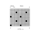
- FIG. 22 shows a state in which CRS is inserted in the subframe.
- the third OFDM symbol from the beginning is PDCCH
- the fourth and subsequent OFDM symbols are PDSCH.
- the resource element portion filled in black corresponds to the CRS signal, but the CRS is inserted in both the PDCCH and PDSCH areas.
- the CRS is transmitted from the eNodeB even when it is not transmitted from the PDSCH user data or the eNodeB. This is because it is assumed that the UE terminal always uses CRS for acquisition of synchronization with eNodeB, channel estimation, eNodeB quality measurement, and the like.
- the CRS uses the same location (that is, the same resource element in the frequency and time directions) in each eNodeB (in FIG. 22, the resource element filled with black is used as the CRS insertion location in common with each eNodeB). Used). For this reason, it is necessary to ensure orthogonality between eNodeBs, and signals having different sequences for each eNodeB are used for CRS. There are 504 sequences in total. If the cell ID of the eNodeB is different, the CRS series is also different. In the sense that it is unique to each cell, it is called the Cell Specific Reference Signal Cell-specific Reference Signal.
- CSI-RS Channel State Information Reference Signal
- RRC Radio Resource Control: Radio Link Control Connection
- CSI-RS is a reference signal newly introduced in Release 3 of 3GPP.
- CSI-RS is a reference signal added for that purpose.
- the location used for transmitting the CSI-RS reference signal can be notified to the UE terminal side by dedicated signaling for each eNodeB. Therefore, CSI-RS is also a signal specific to each cell, and can be called Cell-specific.
- the position of the resource element inserted by CSI-RS in the subframe can also be changed by setting.
- a sequence for improving orthogonality between eNodeBs is also prepared for a signal to be inserted.
- CSI-RS is used as a reference signal for point selection. Since the transmission cycle can be set between 5 milliseconds and 80 milliseconds as described above, the CRS-RS has a great merit that the overhead occupied by the reference signal can be reduced. Also, even eNodeBs having the same Cell ID can assign CSI-RSs to different locations. Even when the same Cell ID is assigned to a plurality of Pico eNodeBs such as RRH as in the case of realizing CoMP by the centralized control method, if the CSI-RS is set separately, the UE terminal It is possible to perform measurement while distinguishing between the two. Therefore, the present inventors consider that CSI-RS is promising as a reference signal for point selection.
- SRS Soliding Reference Signal
- SRS is a reference signal included in the uplink subframe, and exists from Release 8 of 3GPP.
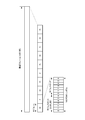
- the SRS is inserted over the entire frequency domain of the last OFDM symbol of the 14 OFDM symbols in the corresponding subframe.
- the insertion period of SRS can be changed from 2 milliseconds to 160 milliseconds.
- the eNodeB acquires the state of the uplink channel based on the SRS and uses it as information for scheduling.
- the uplink channel status can be acquired with little overhead. Since the reversibility of the channel is ensured in the case of TDD, in the case of TDD, it is possible for the eNodeB to use the SRS in order to acquire the status of the downlink channel.
- Scenario 1 is a scenario in which cells are divided into sectors and CoMP is performed between sectors.
- Scenarios 2 to 4 are scenarios in which RMP is used for CoMP.
- RRH transmits with high power equivalent to Macro eNodeB, whereas in scenarios 3 to 4, RRH transmission power is low.
- a unique Cell ID is assigned to each RRH, whereas in Scenario 4, the same Cell ID as that of Macro eNodeB is assigned to each RRH.
- FIG. 1 schematically shows a mode in which Macro eNodeB and a plurality of RRHs subordinate thereto are connected corresponding to scenario 3 and scenario 4.
- the RHH is arranged at a cell edge or the like as a countermeasure against undetection.
- the Macro eNodeB and each RHH (or Pico eNodeB) are connected by a baseband signal using an X2 interface constituted by an optical fiber or the like. Then, the Macro eNodeB performs baseband signal processing and control of each RRH, and collectively performs radio resource control between cells.
- Macro eNodeB and RRH perform CoMP by simultaneously transmitting and receiving data to and from the UE terminal.
- each RRH has its own Cell ID, and the CRS series is also different. Therefore, even if this reference signal is transmitted from each RRH at the same time, the UE terminal can individually acquire the quality for each RRH. That is, in scenario 3, CRS can be used as a reference signal for point selection.
- scenario 4 the same Cell ID as Macro eNodeB is assigned to each RRH, and the CRS sequence is also the same. For this reason, the UE terminal cannot individually acquire the quality for each RRH from the CRS transmitted simultaneously from each RRH. That is, in scenario 4, it is difficult to use CRS as a reference signal for point selection. For this reason, in scenario 4, CSI-RS is considered promising as a reference signal for point selection. In that case, it is necessary to allocate CSI-RS to different locations for each RRH so that the UE terminal side can individually acquire channel information for each RRH (as described above, eNodeB having the same Cell ID) Even so, it is possible to assign CSI-RS to different locations).
- the first problem when performing point selection using CSI-RS The CRS is inserted in every subframe of the downlink. Therefore, the UE terminal can frequently measure the quality of each eNodeB using CRS, and there is an advantage that the frequency of changing the CoMP set is increased.
- scenario 4 since the Macro eNodeB and each RRH connected thereto have the same Cell ID and transmit the same CRS, it is not possible to perform individual measurement for each eNode based on the CRS. . That is, in scenario 4, it is difficult to use CRS as a reference signal for point selection.
- CSI-RS can be used as a reference signal for point selection even in scenario 4, but the frequency of measurement decreases because the transmission cycle is long, and the frequency of point selection updates decreases.
- the frequency of measurement decreases because the transmission cycle is long, and the frequency of point selection updates decreases.
- the CSI-RS transmission cycle is shortened, the frequency of measurement is improved, but the first problem is that the throughput is reduced.
- the UE terminal uses CSI-RS as a reference signal for point selection only in scenario 4, and in other scenarios 1 to 3, CRS is used for point selection. It is used for the reference signal.
- the UE terminal uses CSI-RS or CRS for point selection depending on whether the cell in which it currently exists is scenario 4 or scenarios 1 to 3 I want to determine whether to use for the reference signal.
- the UE terminal does not know whether the cell in which it currently exists is scenario 4 or scenarios 1 to 3. Therefore, there are a method for specifying that the eNodeB performs CSI-RS measurement for the UE terminal, and a method for specifying that the eNodeB is scenario 4 for the UE terminal.
- eNodeB provides means for explicitly instructing the UE terminal. Specifically, the eNodeB informs the UE terminal that measurement of a specific Cell ID is performed using CSI-RS (that is, Cell ID using CSI-RS as a reference signal for point selection), Notification via RRC Signaling.
- CSI-RS that is, Cell ID using CSI-RS as a reference signal for point selection
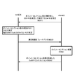
- FIG. 2 shows an example of a communication sequence for performing point selection using CSI-RS only in scenario 4.
- the eNodeB instructs the UE terminal using RRC Signaling to perform measurement for point selection with CSI-RS (not CRS) and feed back the specified Cell ID during measurement for point selection. (M201).
- the UE terminal performs measurement for point selection (P201), but according to the above instruction, the specified Cell ID is measured by CSI-RS, and the unspecified Cell ID is measured by CRS. . Then, the UE terminal feeds back the measurement result of CRS or CSI-RS from the eNodeB of each Cell ID to the eNodeB (M202).
- the eNodeB performs point selection based on information fed back from the UE terminal, and determines a CoMP set for the UE terminal (P202).
- Some operators apply only a single scenario to all cells (a mix of operators using scenario 4 and operators using scenario 3), or one operator applies a different scenario for each cell. There is also a case. In these cases, the UE terminal needs to perform measurement for point selection corresponding to each scenario.
- Second problem when performing point selection using CSI-RS When the CSI-RS transmission period is long, the overhead is small. However, if the CSI-RS transmission period is shortened in order to improve the point selection update frequency, there is a second problem that the overhead increases.
- the CSI-RS transmission cycle is lengthened, overhead is reduced and power saving on the eNodeB side is also achieved. If it is based on the idea that the update frequency of point selection may be reduced if there are few UE terminals that require CoMP, the CSI-RS transmission cycle may be lengthened.
- the CSI-RS transmission cycle is shortened, eNodeB that is no longer needed can be removed from the CoMP set at an early stage by improving the frequency of point selection updates, reducing unnecessary radio wave emissions to the vicinity. can do. If there are few UE terminals that require CoMP, the CSI-RS transmission period may be shortened based on the idea that the load on the eNodeB that performs point selection is small.
- a means for grasping the number of UE terminals that require CoMP and a means for controlling the CSI-RS transmission period based on this number are provided. .
- a UE terminal that requires CoMP is considered to be a UE terminal that exists at a cell edge. Therefore, the eNodeB can estimate the number of UE terminals that require CoMP based on the Timing Advantage value and the number of UE terminals that are determined to be far away by power control.
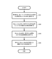
- FIG. 3 shows a processing procedure for controlling the CSI-RS transmission cycle based on the number of UE terminals requiring CoMP in the form of a flowchart.
- the RRH when each RRH grasps the number of UE terminals existing at the cell edge based on the Timing Advantage value and the power control, the RRH notifies the Macro eNodeB of this (Step S301).
- the Macro eNodeB determines the CSI-RS transmission period required for each RRH based on the number of terminals ( In step S303), each RRH is notified.
- Each RRH transmits the CSI-RS at the transmission cycle determined by the Macro eNodeB (step S304).
- means 2-2 for solving the second problem it is possible to use both SRS and CSI-RS as reference signals for point selection to improve the point selection update frequency.
- SRS is a reference signal included in an uplink subframe (described above). Since channel reversibility is ensured during TDD, it is possible for the eNodeB to use SRS in order to acquire the status of the downlink channel.
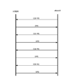
- FIG. 4 shows an example of a communication sequence for performing measurement for point selection using both SRS and CSI-RS. However, it is assumed that TDD is applied in the cell.
- the CSI-RS is transmitted from the eNodeB at a predetermined transmission cycle.
- the UE terminal performs measurement for point selection using CSI-RS and notifies the measurement result to the eNodeB.
- the eNodeB performs measurement for point selection using the SRS included in the uplink subframe from the UE terminal.
- the uplink radio frame from the UE terminal is not particularly limited.
- an SRS included in a radio frame in which a UE terminal feeds back a measurement result for point selection can also be used for measurement.
- the eNodeB performs point selection based on the measurement result fed back from the UE terminal and the measurement result performed by itself, and determines a CoMP set for this UE terminal. Since the measurement for updating the point selection is distributed to both the UE terminal and the eNodeB, the measurement load is reduced for the UE terminal. Thereafter, data transmission / reception with the UE terminal is performed using a CoMP set reflecting the result of the point selection.
- the quality of the downlink channel can also be specified from the uplink SRS. Therefore, as shown in FIG. 4, by using SRS and CSI-RS together for dynamic point selection, the downlink overhead is reduced and the measurement load of the UE terminal can be suppressed. it can.
- the transmission frequency of CSI-RS is given, the overhead of only the downlink increases, but when SRS and CSI-RS are used together, it is given to each of the uplink and downlink Overhead can be equalized.
- the means 2-2 is effective only in the transmission mode of TDD.
- Means 3-1 for solving the above third problem is that the UE terminal receives and measures the reference signal only when the moving speed of the UE is high and the point selection update frequency should be improved. .
- the UE terminal does not necessarily receive and measure all CSI-RSs transmitted from the eNodeB at a predetermined period.
- the UE terminal determines the necessary measurement period according to the moving speed of its own station, selects and receives from the CSI-RS, feeds back the measurement result to the eNodeB, and performs point selection. To get.
- FIG. 5 shows a processing procedure in which the UE terminal feeds back a measurement result to the eNodeB at a measurement cycle corresponding to the moving speed of the own station in a flowchart format.
- the UE terminal determines a necessary measurement cycle of the reference signal based on the moving speed of the own station (step S501).
- the UE terminal measures a reference signal such as CSI-RS transmitted from the eNodeB at a predetermined cycle based on the determined measurement cycle (step S502), and feeds back the measurement result to the eNodeB (step S503). .
- FIG. 6 shows a communication sequence example in which the eNodeB transmits the CSI-RS at a predetermined transmission cycle, whereas the UE terminal receives the CSI-RS at the measurement cycle set by the own station.
- the eNodeB transmits the CSI-RS at a transmission cycle assuming that dynamic point selection is realized at an update frequency desired by the operator, for example.
- measurement is performed by selecting from CSI-RS at a uniquely set measurement period.
- the UE terminal can set the measurement cycle according to the moving speed of the own station, but may set the measurement cycle in consideration of other situations.
- the UE terminal itself can select and measure from the CSI-RS period and omit unnecessary measurements, thereby reducing the power consumption of the terminal itself.
- Means 3-2 can be used in a scenario in which an unnecessary eNodeB is removed from the CoMP set.
- the UE terminal increases the frequency of measuring the reference signal only for the eNodeB whose quality has deteriorated. For example, the UE terminal performs measurement by selecting a CSI-RS transmitted from each eNodeB included in the CoMP set at a predetermined cycle according to a measurement cycle (longer than the transmission cycle) set by itself. Yes.
- the measurement cycle is shortened by that eNodeB, and the measurement is frequently performed.
- the means 3-2 is similar to the means 3-1, in that the UE terminal itself omits unnecessary measurements.
- measurement of the reference signal is started with the degradation of the quality of the Serving eNodeB as a trigger.
- the reference signal is measured, but the frequency of measurement is increased for the eNodeB included in the CoMP set that has a large quality degradation.
- FIG. 7 shows, in the form of a flowchart, a processing procedure for controlling the frequency of measuring the reference signal and removing an eNodeB having a large quality degradation from the CoMP set.
- a threshold value 1 for determining whether to increase the measurement frequency
- a threshold value 2 for determining whether to remove from the CoMP set.
- the UE terminal uses the CSI-RS from the eNodeB belonging to the CoMP set, and performs measurement at the measurement cycle set for each eNodeB (step S701).
- the UE terminal performs CSI-RS measurement for the eNodeB. Measurement is performed at an increased frequency (step S703).
- the UE terminal decreases the CSI-RS measurement frequency for the eNodeB, Measurement is performed (step S707).
- the Serving eNodeB performs dynamic point selection, and removes the eNodeB that is below the threshold 2 from the CoMP set (step S706).
- FIG. 8 schematically shows the result of measuring the quality of each eNodeB at the UE terminal.
- the UE terminal performs CSI-RS measurement for eNodeBs # 1 to # 3. Since the quality of eNodeB # 1 exceeds the threshold value 1, the measurement frequency is not increased. Moreover, since the quality of eNode # 2 is below the threshold value 2, it will be removed from the CoMP set by dynamic point selection. Moreover, since the quality of eNode # 3 is lower than the threshold value 1 but higher than the threshold value 2, the measurement is performed with an increased measurement frequency.
- the means 3-2 can be used for a scenario of searching for an eNodeB to be newly added to the CoMP set.
- the quality of a specific eNodeB is not degraded, but the eNodeB received power included in the current CoMP set searches for an eNodeB that can expect higher received power when the overall quality cannot be maintained. Increase the frequency of measurement.
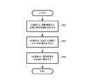
- FIG. 9 shows a processing procedure for searching for an eNodeB to be newly added to the CoMP set by controlling the measurement frequency of the reference signal in the form of a flowchart.
- the UE terminal performs measurement with the CSI-RS corresponding to the new eNodeB while performing the measurement for point selection using the CSI-RS corresponding to each eNodeB included in the CoMP set (step S901).
- the UE terminal increases the measurement frequency for the new eNodeB (step S903).
- the UE terminal decreases the measurement frequency for the new eNodeB (step S904).
- the frequency of the reference signal for point selection is controlled on the eNodeB side according to the number of base stations present in the area performed by the UE terminal.
- the measurement frequency of the reference signal may be controlled on the UE terminal side.
- the CSI-RS transmission cycle from the eNodeB is shortened and the measurement frequency is increased on the UE terminal side.
- the base station for performing CoMP is in an area where there are few base stations, the CSI-RS transmission cycle from the eNodeB is lengthened and the measurement frequency is lowered on the UE terminal side.
- FIG. 10 shows an example of RRH distribution existing in the cell.
- the RRH necessary for performing CoMP changes even if the UE terminal moves a little. For this reason, it is necessary to improve the point selection update frequency, and the UE terminal side increases the measurement frequency.
- the base stations necessary for performing CoMP do not change much as the UE terminal moves. There is no need to increase the point selection update frequency.
- FIG. 11 shows a processing procedure for controlling the frequency of CSI-RS transmission from the eNodeB in accordance with the RRH density in the form of a flowchart.
- the Macro eNodeB acquires RRH arrangement information in its own cell (step S1101).
- the Macro eNodeB instructs the transmission frequency of CSI-RS to each RRH in consideration of the density of RRHs in its own cell (step S1102).
- the RRH transmits the CSI-RS at the transmission frequency instructed from the Macro eNodeB (step S1103).
- FIG. 12 shows a processing procedure for the UE terminal to control the reception frequency of CSI-RS from the eNodeB according to the RRH density in the form of a flowchart.
- the Macro eNodeB When the Macro eNodeB acquires the arrangement information of the RRH in the own cell (step S1201), the Macro eNodeB notifies each RRH in the own cell of the density of the RRH (step S1202).
- each RRH further notifies the UE terminal of the notified RRH density (step S1203).
- the UE terminal determines the frequency with which the terminal receives the CSI-RS based on the notified RRH density, and performs point selection measurement (step S1204).
- carrier aggregation technology is introduced.
- the means 4-1 for solving the fourth problem, there is a method of controlling the frequency of transmitting CSI-RS according to the degree of CoMP recommendation for each component carrier. That is, the means 4-1 increases the frequency of transmitting CSI-RS in the component carrier that recommends CoMP.
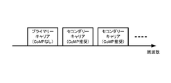
- one major carrier is designated as “primary carrier”, and one or more other carriers are designated as “secondary carriers”.
- CoMP is not recommended for the primary carrier, in other words, the secondary carrier is operated as a component carrier specialized for CoMP (see FIG. 13).
- the CSI-RS transmission frequency of the secondary component carrier is increased as compared with the primary component carrier.
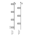
- means 4-2 for solving the fourth problem there is a method of controlling the frequency of transmitting CSI-RS according to the channel change in the component carrier.
- a component carrier with a higher frequency has a larger channel change than a component carrier with a lower frequency. Therefore, the frequency with which CSI-RS is transmitted is set higher in the component carrier having a higher frequency than in the component carrier having a lower frequency (see FIG. 14).
- the frequency of CSI-RS transmission is reduced as a whole system by sharing the measurement result of the reference signal between adjacent component carriers on the frequency axis. Can be mentioned.
- CSI-RS is transmitted only on one component carrier 1, and CSI is transmitted on the other component carrier 2.
- the RS is not transmitted, but the measurement result in the component carrier 2 is used.
- the component carrier 1 and the component carrier 2 are adjacent on the frequency axis, the component carrier 1 and the component carrier 2 are shared so as not to overlap on the time axis and the frequency axis as shown in FIG. Then, the CSI-RS may be transmitted.
- the fifth problem when performing point selection using CSI-RS When the number of RRHs belonging to Macro eNodeB is large, there is a fifth problem that when CSI-RS is transmitted from each RRH, overhead is increased by CSI-RS, and downlink throughput is reduced.
- RRHs and eNodeBs belonging to the same CoMP set can be classified into RRHs that are measured by the UE terminal and are included in the CoMP set, and RRHs that are not included in the CoMP set.
- the RRH CSI-RS frequently used for CoMP should be transmitted in a short cycle, and conversely, the eNodeB CSI-RS not frequently used for CoMP should be transmitted in a long cycle.
- the Serving eNodeB aggregates the number of UE terminals in the radio link control connection state (that is, RRC-Connected) with each RRH, and the CSI for each RRH according to the number of UE terminals in the radio link control connection state. -The RS transmission frequency should be set.
- FIG. 17 shows a processing procedure for controlling the transmission cycle of the RRH CSI-RS in accordance with the usage status of the CoMP set in the form of a flowchart.
- the Macro eNodeB acquires the number of UE terminals that are in the radio link control connection state (that is, RRC-Connected) (step S1701).
- the Macro eNodeB sets the CSI-RS transmission frequency for each RRH according to the number of UE terminals in the radio link control connection state (step S1702), the set CSI-RS transmission frequency for each RRH. Is notified (step S1703).
- FIG. 18 schematically shows a configuration example of a radio communication device 1800 that operates as Macro eNodeB in the radio communication system (FIG. 1) according to the present embodiment.
- Macro eNodeB includes radio resource management in Macro Cell, transmission of various reference signals, RRC Signaling to UE terminal, measurement of reference signal SRS included in uplink radio frame from UE terminal, etc.
- the functional modules that perform the basic operations are appropriately omitted.
- the wireless communication apparatus 1800 includes an RF communication processing unit 1801 that performs analog processing of a radio signal transmitted and received by an antenna, and a digital communication processing unit 1802 that performs modulation of a digital transmission signal and demodulation processing of a digital reception signal.
- the digital communication processing unit 1802 exchanges transmission / reception data with the upper layer protocol of the communication layer of the own device 1800.
- the digital communication processing unit 1802 communicates with other eNodeBs via an X2 interface, S-GW (Serving Gateway), and MME (Mobility Management Entity). Also, the digital communication processing unit 1802 performs baseband signal processing and control of each RRH subordinate to the own device 1800 via the X2 interface.
- the RRH information acquisition unit 1803 acquires information about RRHs subordinate to the device 1800 from each RRH using an X2 interface such as an optical fiber.
- the RRH information acquisition unit 1803 acquires information necessary for realizing the above-described means 2-1, 3-3, and means 6 from each RRH. Examples of information to be acquired include the number of UE terminals in the RRH and radio link control connection state (RRC_Connected), the density of RRHs in the own cell, and the like.
- the transmission frequency control unit 1804 controls the transmission frequency of the CSI-RS of each RRH subordinate to the own device 1800.
- the transmission frequency control unit 1804 functions as one of the above-described means 2-1, means 2-2, means 3-3, means 4-1, means 4-2, means 4-3, and means 5.
- the carrier determination unit 1805 determines the importance of performing CoMP for each component carrier when performing carrier aggregation.
- the carrier determination unit 1805 performs determination for determining a component carrier that uses CoMP (or recommends the use of CoMP) when realizing the above-described means 5-1.
- the notification unit 1806 notifies the transmission frequency of the CSI-RS determined by the transmission frequency control unit 1804 to each Pico eNodeB (including RRH) subordinate to the device 1800. Also, the notification unit 1806 notifies the UE terminals belonging to the Pico eNodeB of the CSI-RS measurement frequency and the like as necessary. The notification unit 1806 notifies the corresponding Pico eNodeB when realizing the above-described means 2-1, means 3-3, means 4-1, means 4-2, means 4-3, and means 5. Also, the notification unit 1806 performs necessary notification to the UE terminal when realizing the above-described means 1 and means 3-3.
- the radio communication apparatus 1800 can acquire the CSI-RS measurement result, that is, feedback for point selection, from the UE terminal at a desired frequency. Based on this feedback information, the point selection unit 1807 configures a CoMP set with the minimum necessary eNodeB that satisfies the quality required for the UE terminal. In addition, the point selection unit 1807 performs the point selection based on both feedback information from the UE terminal and the result of measuring the SRS included in the uplink from the UE terminal, whereby the above-described means 2-2 Is realized.
- FIG. 19 schematically shows a configuration example of a wireless communication apparatus 1900 that operates as a Pico eNodeB or RRH in the wireless communication system (FIG. 1) according to the present embodiment.
- functional modules that perform basic operations as a Pico eNodeB such as radio resource management in the Pico Cell and RRC signaling to the UE terminal, are appropriately omitted.
- the wireless communication apparatus 1900 includes an RF communication processing unit 1901 that performs analog processing of a radio signal transmitted and received by an antenna, and a digital communication processing unit 1902 that performs modulation of a digital transmission signal and demodulation processing of a digital reception signal.
- the digital communication processing unit 1902 exchanges transmission / reception data with the upper layer protocol of the communication layer of the own device 1900.
- the digital communication processing unit 1902 communicates with other eNodeBs via an X2 interface, S-GW (Serving Gateway), and MME (Mobility Management Entity).
- S-GW Serving Gateway
- MME Mobility Management Entity
- the transmission frequency control unit 1903 controls the frequency of CSI-RS transmitted from the own device 1900.
- the transmission frequency control unit 1903 determines the CSI-RS transmission frequency according to the notification from the Macro eNodeB (Serving Macro eNodeB) to which the device 1900 is subordinate, and the above-described means 2-1, means 2-2, means 3- 3. Contributes to the realization of the means 4-1, means 4-2, means 4-3, and means 4.
- the measurement frequency notification unit 1904 instructs the UE terminal belonging to the device 1900 about the CSI-RS measurement frequency, and This contributes to the realization of means 1 and means 3-3.
- the setting information acquisition unit 1905 acquires various types of information set by the Serving eNodeB for the own device 1900 such as the frequency of CSI-RS transmitted from the own device 1900 via the X2 interface.
- FIG. 20 schematically illustrates a configuration example of a wireless communication device 2000 that operates as a UE terminal in the wireless communication system (FIG. 1) according to the present embodiment.
- functional modules that perform basic operations as a UE terminal are omitted as appropriate.
- the wireless communication device 2000 includes an RF communication processing unit 2001 that performs analog processing of a wireless signal transmitted and received by an antenna, and a digital communication processing unit 2002 that performs modulation of a digital transmission signal and demodulation processing of a digital reception signal.
- the digital communication processing unit 2002 exchanges transmission / reception data with the upper layer protocol of the communication layer of the own device 2000.
- the measurement frequency control unit 2003 controls the frequency at which the own device 2000 measures a reference signal for point selection such as CSI-RS.
- the measurement frequency control unit 2003 realizes the above-described unit 3-1 by controlling the CSI-RS measurement frequency according to the moving speed of the own device 2000, for example.
- the measurement frequency control unit 2003 realizes the above-described means 3-2 by controlling the measurement frequency of CSI-RS from each eNode in the CoMP set based on the communication quality.
- the measurement frequency control unit 2003 realizes the above-described means 1 by controlling CRS for scenario 3 and CSI-RS for scenario 4 for point selection.
- the measurement frequency information acquisition unit 2004 acquires information related to setting of the CSI-RS measurement frequency from the eNodeB (Serving Pico eNodeB) to which the device 2000 belongs.
- the measurement frequency information acquisition unit 2004 acquires information for identifying a scenario applied in a cell as information regarding the measurement frequency. By measuring the CSI-RS according to the measurement frequency acquired by the measurement frequency information acquisition unit 2004, it contributes to the realization of the means 1 and means 3-3 described above.
- the reference signal measurement unit 2005 measures the reference signal for point selection such as CSI-RS based on the measurement frequency determined by the measurement frequency control unit 2003 or the measurement frequency acquired by the measurement frequency information acquisition unit 2004. Do.
- the reference signal measurement unit 2005 performs point selection measurement using CRS in scenario 3 and performs point selection measurement using CSI-RS in scenario 4 by switching the reference signal. Means 1 described above is realized.
- a measurement result by the reference signal measurement unit 2005 is transmitted to the Serving Pico eNodeB via the digital communication processing unit 2002 and the RF communication processing unit 2001.
- the present embodiment it is possible to improve the point selection update frequency while suppressing the overhead of the reference signal for the point selection. As a result, the effect of improving the throughput of the cell, that is, the communication system can be obtained.
- a measurement control unit that sets the type of reference signal to be measured for determination of a cooperative group that performs multipoint coordinated transmission / reception for its own device, and the measurement control unit that is transmitted from each base station. And a reference signal measuring unit that measures a reference signal of a different type for determining the cooperative group.
- the wireless communication device according to (1) wherein the measurement control unit sets a type of a reference signal to be measured for determination of a cooperation group according to a scenario applied in a current cell.
- Each base station can be assigned to a different location between base stations having the same cell identifier and the base station having the same cell identifier is the same as the first reference signal capable of adjusting the transmission cycle.
- the measurement control unit sets the first reference signal for measurement for determining a cooperative group
- the second reference signal is set for measurement for determining a cooperative group
- the radio according to (2) above Communication device.
- Each base station has the same base station having the same cell identifier as the first reference signal that can be assigned to different locations between base stations having the same cell identifier and whose transmission cycle can be adjusted.
- a second reference signal using the location of the base station, and the measurement control unit sends the first reference signal to the base station having the specific cell identifier notified from the base station for determining the cooperative group.
- the first reference signal that can be allocated to different locations between base stations having the same cell identifier and can adjust the transmission cycle, and the same location is used between base stations having the same cell identifier
- a reference signal transmission unit that transmits a second reference signal and a terminal that belongs to the own device according to a scenario that is applied in the current cell.
- a notification unit that notifies a cell identifier to be measured.
- the notifying unit uses the first reference signal to determine a cooperation group for a terminal belonging to the own device.
- the wireless communication device according to (6) which notifies a cell identifier to be measured.
- a subordinate base station information acquiring unit that acquires base station information subordinate to the own device, and a cooperative group that performs multipoint coordinated transmission / reception based on the base station information acquired by the subordinate base station information acquiring unit
- a wireless communication apparatus comprising: a transmission frequency control unit that controls a frequency at which a reference signal for determination is transmitted; and a notification unit that notifies control information by the transmission frequency control unit to each base station.
- the subordinate base station information acquisition unit acquires information on the number of terminals that require multipoint coordinated transmission / reception from a base station subordinate to the own device, and the transmission frequency control unit performs multipoint coordinated transmission / reception.
- the wireless communication device according to (8), wherein the frequency of transmitting a reference signal is controlled according to the number of required terminals.
- the transmission frequency control unit increases a cycle of transmitting a reference signal when the number of terminals that require multipoint coordinated transmission / reception is small.
- a reference signal transmission unit that transmits a first reference signal, a feedback information acquisition unit that acquires feedback of a measurement result of the first reference signal from a terminal, and a second reference signal transmitted from the terminal
- a wireless communication device comprising a selection unit.
- the point selection unit performs multipoint coordinated transmission / reception for the terminal station based on the measurement result of the measurement unit together with the feedback information acquired by the feedback information acquisition unit.
- the wireless communication apparatus according to (11), wherein a cooperation group to be performed is determined.
- a reference signal measuring unit that measures a reference signal transmitted from each base station for determining a cooperative group that performs multipoint coordinated transmission / reception for the own device, and the reference signal based on the moving speed of the own device
- a wireless communication apparatus comprising: a measurement frequency control unit that controls a frequency at which measurement is performed in the measurement unit.
- the measurement frequency control unit causes the reference signal measurement unit to perform measurement only when the moving speed of the device itself is high.
- a radio communication apparatus comprising: a measurement frequency control unit that controls a measurement frequency for each base station in the reference signal measurement unit.
- the measurement frequency control unit increases the measurement frequency for a base station in which degradation of communication quality is detected based on a measurement result in the reference signal measurement unit.
- the measurement frequency control unit increases the measurement frequency for a new base station that is not included in the cooperation group when detecting a base station having a deteriorated communication quality in the cooperation group.
- the subordinate base station information acquisition unit acquires arrangement information of base stations subordinate to the own device, and the transmission frequency control unit transmits a reference signal according to a density of base stations subordinate to the own device.
- the wireless communication device according to (18), wherein the transmission frequency control unit increases the frequency of transmitting a reference signal in an area where the density of base stations subordinate to the device is large.
- a base station information acquisition unit that acquires arrangement information of base stations that can be incorporated into a cooperation group that performs multipoint coordinated transmission / reception for its own device, and a base station based on the acquired arrangement information of base stations
- a measurement frequency control unit that controls the frequency at which the reference signal from the base station is measured for determining the cooperative group, and a reference signal measurement unit that measures the reference signal from the base station according to the frequency controlled by the measurement frequency control unit.
- a wireless communication device provided.
- a carrier determination unit that determines the importance of performing multipoint coordinated transmission / reception for each component carrier when performing carrier aggregation, and a multipoint at each component carrier based on a determination result in the carrier determination unit.
- a radio communication apparatus comprising: a transmission frequency control unit that controls a frequency of transmitting a reference signal for determining a cooperative group that performs cooperative transmission and reception; and a notification unit that notifies control information by the transmission frequency control unit to each base station .
- a transmission frequency control unit that controls the frequency of transmitting a reference signal for determining a coordination group that performs multipoint coordinated transmission / reception in each component carrier according to frequency when performing carrier aggregation, and the transmission frequency
- a wireless communication apparatus comprising: a notification unit that notifies each base station of control information from the control unit.
- a transmission frequency control unit that controls the frequency of transmitting a reference signal for determining a coordination group that performs multipoint coordinated transmission / reception in each component carrier according to the frequency arrangement; And a notification unit that notifies each base station of control information by the transmission frequency control unit.
- the transmission frequency control unit transmits a reference signal only to one of component carriers arranged consecutively in frequency.
- the reference signal is transmitted so that the component carriers arranged consecutively in frequency do not overlap in time and frequency. Wireless communication device.
- the subordinate base station information acquisition unit acquires information on the number of terminals that are in a radio link control connection state with each base station subordinate to the own device, and the transmission frequency control unit is in a radio link control connection state.
- the radio communication device according to (8), wherein the frequency at which each base station subordinate to the own device transmits a reference signal is controlled according to the number of certain terminals.
- the transmission frequency control unit increases the frequency of transmitting a reference signal from a base station having a large number of terminals in a radio link control connection state.
- (31) Set in the measurement control step for setting the type of reference signal to be measured for determination of the cooperative group for performing multipoint cooperative transmission / reception for the own device, and the measurement control step transmitted from each base station
- (32) A first reference signal that can be assigned to different locations between base stations having the same cell identifier and whose transmission period can be adjusted, and the same location is used between base stations having the same cell identifier
- a subordinate base station information acquisition step for acquiring information on base stations subordinate to the own device, and a cooperative group that performs multipoint coordinated transmission / reception based on the base station information acquired in the subordinate base station information acquisition step.
- a wireless communication method comprising: a transmission frequency control step for controlling a frequency of transmitting a reference signal for determination; and a notification step for notifying each base station of control information obtained by the transmission frequency control step.
- a wireless communication method comprising: feedback information acquired in an acquisition step; and a point selection step of determining a cooperative group that performs multipoint coordinated transmission / reception for a terminal station based on a measurement result of the measurement step.
- a measurement frequency control step for controlling the frequency of measuring the reference signal transmitted from each base station based on the moving speed of the own device, and the reference signal according to the frequency controlled in the measurement frequency control step.
- a reference signal measurement step for measuring for cooperative group determination for performing multipoint coordinated transmission / reception for the apparatus.
- a base station information acquisition step for acquiring base station arrangement information that can be incorporated into a cooperative group that performs multipoint coordinated transmission / reception for the own device, and a base station based on the acquired base station arrangement information
- a measurement frequency control step for controlling the frequency at which the reference signal from the base station is measured for determining the cooperative group, and a reference signal measurement step for measuring the reference signal from the base station according to the frequency controlled in the measurement frequency control step.
- a carrier determination step for determining the importance of performing multipoint coordinated transmission / reception for each component carrier when performing carrier aggregation, and a multipoint at each component carrier based on the determination result in the carrier determination step.
- a wireless communication method comprising: a transmission frequency control step for controlling a frequency of transmitting a reference signal for determining a cooperative group for performing cooperative transmission / reception; and a notification step for notifying each base station of control information by the transmission frequency control step.
- a transmission frequency control step for controlling the frequency of transmitting a reference signal for determining a coordination group for performing multipoint coordinated transmission / reception in each component carrier according to the frequency when performing carrier aggregation, and the transmission frequency And a notification step of notifying each base station of control information by the control step.
- a transmission frequency control step for controlling the frequency of transmitting a reference signal for determining a cooperation group that performs multipoint coordinated transmission / reception in each component carrier according to the frequency arrangement; And a notification step of notifying each base station of control information in the transmission frequency control step.
- a plurality of base stations that respectively transmit a plurality of types of reference signals, and a type of reference signal to be measured for determination of a cooperation group that performs multipoint coordinated transmission / reception for the own station.
- a wireless communication system comprising: a terminal station that performs measurement of (42) A first reference signal that can be assigned to different locations between base stations having the same cell identifier and whose transmission cycle can be adjusted, and base stations having the same cell identifier use the same location A plurality of base stations that respectively transmit the second reference signals to be transmitted, and a terminal station that performs measurement for determining a cooperation group that receives the reference signals and performs multipoint coordinated transmission / reception for the local station, A wireless communication system in which at least one of the base stations notifies a terminal identifier belonging to the own station of a cell identifier to be measured for determination of a cooperative group using a first reference signal.
- a plurality of base stations that transmit the first reference signal and a measurement for determining a cooperation group that receives the first reference signal and performs multipoint coordinated transmission / reception for the local station to the base station
- a terminal station that feeds back and transmits a second reference signal, and at least one of the plurality of base stations is configured to measure feedback information from the terminal station and measurement of the second reference signal at the own station;
- a wireless communication system that determines a cooperation group that performs multipoint cooperative transmission / reception for the terminal station based on a result.
- a plurality of base stations that transmit reference signals, and a reference signal received at a frequency according to the moving speed of the local station, and measurement for determining a cooperative group that performs multipoint coordinated transmission / reception for the local station.
- a wireless communication system (46) A plurality of base stations that transmit reference signals, and a terminal station that receives the reference signals from the base stations and performs measurement for determining a cooperative group that performs multipoint coordinated transmission / reception for the local station.
- the terminal station is a wireless communication system that controls the measurement frequency for each base station based on the measurement result of the reference signal from each base station.
- (47) A plurality of base stations that transmit reference signals, and a terminal station that receives the reference signals from the base stations and performs measurement for determining a cooperative group that performs multipoint coordinated transmission / reception for the local station.
- the terminal station controls a frequency of measuring a reference signal from a base station based on arrangement information of base stations that can be incorporated into a cooperation group.
- the frequency at which at least one of the plurality of base stations transmits a reference signal for each component carrier based on the importance of performing multipoint coordinated transmission / reception in each component carrier when performing carrier aggregation A wireless communication system for controlling.
- (49) A plurality of base stations that transmit reference signals, and a terminal station that receives the reference signals from the base stations and performs measurement for determining a cooperation group that performs multipoint coordinated transmission / reception for the own station.
- a wireless communication system in which at least one of the plurality of base stations controls the frequency of transmitting a reference signal for each component carrier according to the frequency of each component carrier when performing carrier aggregation.
- a plurality of base stations that transmit reference signals, and a terminal station that receives the reference signals from the base stations and performs measurement for determining a cooperative group that performs multipoint coordinated transmission / reception for the local station.
- At least one of the plurality of base stations, when performing carrier aggregation, each of the component carriers that are consecutively arranged in frequency according to the frequency arrangement of each component carrier is referred to A wireless communication system for controlling the frequency of signal transmission.
- the embodiment applied to the cellular communication system according to LTE established by 3GPP has been mainly described, but the gist of the technology disclosed in this specification is not limited to this.
- the technology disclosed in this specification can be similarly applied to various cellular communication systems to which a technology in which a plurality of base stations cooperate and transmit / receive data to / from a terminal simultaneously is applied.
- Wireless communication device (Macro eNodeB) 1801 ... RF communication processing unit 1802 ... digital communication processing unit 1803 ... RRH information acquisition unit 1804 ... transmission frequency control unit 1805 ... carrier determination unit 1806 ... notification unit 1807 ... point selection unit 1900 ... wireless communication device (Pico eNodeB or RRH) 1901: RF communication processing unit 1902 ... Digital communication processing unit 1903 ... Transmission frequency control unit 1904 ... Measurement frequency notification unit 1905 ... Setting information acquisition unit 2000 ... Wireless communication apparatus (UE terminal) 2001 ... RF communication processing unit 2002 ... Digital communication processing unit 2003 ... Measurement frequency control unit 2004 ... Measurement frequency information acquisition unit 2005 ... Reference signal measurement unit
Landscapes
- Engineering & Computer Science (AREA)
- Signal Processing (AREA)
- Computer Networks & Wireless Communication (AREA)
- Computer Security & Cryptography (AREA)
- Mobile Radio Communication Systems (AREA)
Abstract
Description
ある1つのUE端末に対してCoMPを行なう、すなわち協調グループを構成するeNodeBの組合せを、以下では、Set of CoMP transmission point、又は、略してCoMPセットと呼ぶことにする。
ポイント・セレクションは、ある一定期間毎に行なう必要がある(すなわち、CoMPセットを一定時間毎に更新する必要がある)。つまり、UE端末のCoMPセットを、準静的(Semi-Static)に更新するか、動的(Dynamic)に更新するかという問題がある。UE端末の移動を考慮すると、CoMPセットを動的に更新する、ダイナミック・ポイント・セレクションが望ましい。
ダイナミック・ポイント・セレクションを行なう場合、システム内での通信シーケンス中でリファレンス信号が占めることによるスループットの低下、言い換えればリファレンス信号によるダウンリンクのオーバーヘッドを考慮する必要がある。
自装置のための多地点協調送受信を行なう協調グループの決定のために測定するリファレンス信号の種類を設定する測定制御部と、
各基地局から送信される、前記測定制御部で設定された種類のリファレンス信号を、前記協調グループ決定用に測定するリファレンス信号測定部と、
を具備する無線通信装置である。
同一のセル識別子を持つ基地局間で互いに異なる場所に割り当てることが可能で送信周期を調整可能な第1のリファレンス信号と、同一のセル識別子を持つ基地局同士で同一の場所を使用する第2のリファレンス信号を送信するリファレンス信号送信部と、
現在のセルで適用されているシナリオに応じて、自装置に属する端末に対して、第1のリファレンス信号を用いて協調グループ決定用の測定を行なうべきセル識別子を通知する通知部と、
を具備する無線通信装置である。
自装置に従属する基地局の情報を取得する従属基地局情報取得部と、
前記従属基地局情報取得部が取得した基地局の情報に基づいて、多地点協調送受信を行なう協調グループの決定用のリファレンス信号を送信する頻度を制御する送信頻度制御部と、
前記送信頻度制御部による制御情報を各基地局に通知する通知部と、
を具備する無線通信装置である。
第1のリファレンス信号を送信するリファレンス信号送信部と、
端末から第1のリファレンス信号の測定結果のフィードバックを取得するフィードバック情報取得部と、
前記端末から送信される第2のリファレンス信号を測定するリファレンス信号を測定する測定部と、
前記フィードバック情報取得部が取得したフィードバック情報と、前記測定部の測定結果に基づいて、端末局のための多地点協調送受信を行なう協調グループを決定するポイント・セレクション部と、
を具備する無線通信装置である。
各基地局から送信されるリファレンス信号を、自装置のための多地点協調送受信を行なう協調グループ決定用に測定するリファレンス信号測定部と、
自装置の移動速度に基づいて、前記リファレンス信号測定部において測定を行なう頻度を制御する測定頻度制御部と、
を具備する無線通信装置である。
各基地局から送信されるリファレンス信号を、自装置のための多地点協調送受信を行なう協調グループ決定用に測定するリファレンス信号測定部と、
前記リファレンス信号測定部における測定結果に基づいて、前記リファレンス信号測定部における基地局毎の測定頻度を制御する測定頻度制御部と、
を具備する無線通信装置である。
自装置のための多地点協調送受信を行なう協調グループに組み込むことが可能な基地局の配置情報を取得する基地局情報取得部と、
取得した基地局の配置情報に基づいて、基地局からのリファレンス信号を前記協調グループ決定用に測定する頻度を制御する測定頻度制御部と、
前記測定頻度制御部で制御する頻度に従って、基地局からのリファレンス信号を測定するリファレンス信号測定部と、
を具備する無線通信装置である。
キャリア・アグリゲーションを行なう際に、多地点協調送受信を行なう重要性をコンポーネント・キャリア毎に判定するキャリア判定部と、
前記キャリア判定部における判定結果に基づいて、各コンポーネント・キャリアで多地点協調送受信を行なう協調グループの決定用のリファレンス信号を送信する頻度を制御する送信頻度制御部と、
前記送信頻度制御部による制御情報を各基地局に通知する通知部と、
を具備する無線通信装置である。
キャリア・アグリゲーションを行なう際に、周波数に応じて各コンポーネント・キャリアで多地点協調送受信を行なう協調グループの決定用のリファレンス信号を送信する頻度を制御する送信頻度制御部と、
前記送信頻度制御部による制御情報を各基地局に通知する通知部と、
を具備する無線通信装置である。
キャリア・アグリゲーションを行なう際に、周波数的な配置に応じて各コンポーネント・キャリアで多地点協調送受信を行なう協調グループの決定用のリファレンス信号を送信する頻度を制御する送信頻度制御部と、
前記送信頻度制御部による制御情報を各基地局に通知する通知部と、
を具備する無線通信装置である。
自装置のための多地点協調送受信を行なう協調グループの決定のために測定するリファレンス信号の種類を設定する測定制御ステップと、
各基地局から送信される、前記測定制御ステップで設定された種類のリファレンス信号を、前記協調グループ決定用に測定するリファレンス信号測定ステップと、
を有する無線通信方法である。
同一のセル識別子を持つ基地局間で互いに異なる場所に割り当てることが可能で送信周期を調整可能な第1のリファレンス信号と、同一のセル識別子を持つ基地局同士で同一の場所を使用する第2のリファレンス信号を送信するリファレンス信号送信ステップと、
現在のセルで適用されているシナリオに応じて、自装置に属する端末に対して、第1のリファレンス信号を用いて協調グループ決定用の測定を行なうべきセル識別子を通知する通知ステップと、
を有する無線通信方法である。
自装置に従属する基地局の情報を取得する従属基地局情報取得ステップと、
前記従属基地局情報取得ステップで取得した基地局の情報に基づいて、多地点協調送受信を行なう協調グループの決定用のリファレンス信号を送信する頻度を制御する送信頻度制御ステップと、
前記送信頻度制御ステップによる制御情報を各基地局に通知する通知ステップと、
を有する無線通信方法である。
端末から第1のリファレンス信号の測定結果のフィードバックを取得するフィードバック情報取得ステップと、
前記端末から送信される第2のリファレンス信号を測定するリファレンス信号を測定する測定ステップと、
前記フィードバック情報取得ステップで取得したフィードバック情報と、前記測定ステップの測定結果に基づいて、端末局のための多地点協調送受信を行なう協調グループを決定するポイント・セレクション・ステップと、
を有する無線通信方法である。
各基地局から送信されるリファレンス信号を測定する頻度を自装置の移動速度に基づいて制御する測定頻度制御ステップと、
前記測定頻度制御ステップで制御される頻度に従って、リファレンス信号を、自装置のための多地点協調送受信を行なう協調グループ決定用に測定するリファレンス信号測定ステップと、
を有する無線通信方法である。
各基地局から送信されるリファレンス信号を、自装置のための多地点協調送受信を行なう協調グループ決定用に測定するリファレンス信号測定ステップと、
前記リファレンス信号測定ステップにおける測定結果に基づいて、前記リファレンス信号測定部における基地局毎の測定頻度を制御する測定頻度制御ステップと、
を有する無線通信方法である。
自装置のための多地点協調送受信を行なう協調グループに組み込むことが可能な基地局の配置情報を取得する基地局情報取得ステップと、
取得した基地局の配置情報に基づいて、基地局からのリファレンス信号を前記協調グループ決定用に測定する頻度を制御する測定頻度制御ステップと、
前記測定頻度制御ステップで制御する頻度に従って、基地局からのリファレンス信号を測定するリファレンス信号測定ステップと、
を有する無線通信方法である。
キャリア・アグリゲーションを行なう際に、多地点協調送受信を行なう重要性をコンポーネント・キャリア毎に判定するキャリア判定ステップと、
前記キャリア判定ステップにおける判定結果に基づいて、各コンポーネント・キャリアで多地点協調送受信を行なう協調グループの決定用のリファレンス信号を送信する頻度を制御する送信頻度制御ステップと、
前記送信頻度制御ステップによる制御情報を各基地局に通知する通知ステップと、
を有する無線通信方法である。
キャリア・アグリゲーションを行なう際に、周波数に応じて各コンポーネント・キャリアで多地点協調送受信を行なう協調グループの決定用のリファレンス信号を送信する頻度を制御する送信頻度制御ステップと、
前記送信頻度制御ステップによる制御情報を各基地局に通知する通知ステップと、
を有する無線通信方法である。
キャリア・アグリゲーションを行なう際に、周波数的な配置に応じて各コンポーネント・キャリアで多地点協調送受信を行なう協調グループの決定用のリファレンス信号を送信する頻度を制御する送信頻度制御ステップと、
前記送信頻度制御ステップによる制御情報を各基地局に通知する通知ステップと、
を有する無線通信方法である。
それぞれ複数の種類のリファレンス信号を送信する複数の基地局と、
自局のための多地点協調送受信を行なう協調グループの決定のために測定するリファレンス信号の種類を設定して、リファレンス信号の測定を行なう端末局と、
を具備する無線通信システムである。
同一のセル識別子を持つ基地局間で互いに異なる場所に割り当てることが可能で送信周期を調整可能な第1のリファレンス信号と、同一のセル識別子を持つ基地局同士で同一の場所を使用する第2のリファレンス信号をそれぞれ送信する複数の基地局と、
リファレンス信号を受信して自局のための多地点協調送受信を行なう協調グループの決定用の測定を行なう端末局と、
を具備し、
前記複数の基地局うち少なくともいずれか1つは、自局に属する端末局に対して、第1のリファレンス信号を用いて協調グループ決定用の測定を行なうべきセル識別子を通知する、
無線通信システムである。
リファレンス信号を送信する複数の基地局と、
基地局からのリファレンス信号を受信して自局のための多地点協調送受信を行なう協調グループの決定用の測定を行なう端末局と、
を具備し、
前記複数の基地局うち少なくともいずれか1つは、自局に従属する基地局から取得した情報に基づいて、各基地局がリファレンス信号を送信する頻度を制御する、
無線通信システムである。
第1のリファレンス信号を送信する複数の基地局と、
第1のリファレンス信号を受信して自局のための多地点協調送受信を行なう協調グループの決定用の測定を行なって基地局にフィードバックするとともに第2のリファレンス信号を送信する端末局と、
を具備し、
前記複数の基地局うち少なくともいずれか1つは、前記端末局からのフィードバック情報と、自局での第2のリファレンス信号の測定結果に基づいて、前記端末局のための多地点協調送受信を行なう協調グループを決定する、
無線通信システムである。
リファレンス信号を送信する複数の基地局と、
自局の移動速度に応じた頻度でリファレンス信号を受信して、自局のための多地点協調送受信を行なう協調グループの決定用の測定を行なう端末局と、
を具備する無線通信システムである。
リファレンス信号を送信する複数の基地局と、
基地局からのリファレンス信号を受信して、自局のための多地点協調送受信を行なう協調グループの決定用の測定を行なう端末局と、
を具備し、
前記端末局は、各基地局からのリファレンス信号の測定結果に基づいて、基地局毎の測定頻度を制御する、
無線通信システムである。
リファレンス信号を送信する複数の基地局と、
基地局からのリファレンス信号を受信して、自局のための多地点協調送受信を行なう協調グループの決定用の測定を行なう端末局と、
を具備し、
前記端末局は、協調グループに組み込むことが可能な基地局の配置情報に基づいて、基地局からのリファレンス信号を測定する頻度を制御する、
無線通信システムである。
リファレンス信号を送信する複数の基地局と、
基地局からのリファレンス信号を受信して、自局のための多地点協調送受信を行なう協調グループの決定用の測定を行なう端末局と、
を具備し、
前記複数の基地局うち少なくともいずれか1つは、キャリア・アグリゲーションを行なう際に、各コンポーネント・キャリアで多地点協調送受信を行なう重要性に基づいて、コンポーネント・キャリア毎にリファレンス信号を送信する頻度を制御する、
無線通信システムである。
リファレンス信号を送信する複数の基地局と、
基地局からのリファレンス信号を受信して、自局のための多地点協調送受信を行なう協調グループの決定用の測定を行なう端末局と、
を具備し、
前記複数の基地局うち少なくともいずれか1つは、キャリア・アグリゲーションを行なう際に、各コンポーネント・キャリアの周波数に応じて、コンポーネント・キャリア毎にリファレンス信号を送信する頻度を制御する、
無線通信システムである。
リファレンス信号を送信する複数の基地局と、
基地局からのリファレンス信号を受信して、自局のための多地点協調送受信を行なう協調グループの決定用の測定を行なう端末局と、
を具備し、
前記複数の基地局うち少なくともいずれか1つは、キャリア・アグリゲーションを行なう際に、各コンポーネント・キャリアの周波数的な配置に応じて、周波数的に連続して配置されたコンポーネント・キャリアでそれぞれリファレンス信号を送信する頻度を制御する、
無線通信システムである。
CRSは、ダウンリンクのすべてのサブフレームに挿入されている。したがって、UE端末は、CRSを用いて頻繁の各eNodeBの品質の測定を行なうことが可能であり、CoMPセットを変更する頻度が高くなるというメリットがある。しかしながら、シナリオ4の場合には、Macro eNodeBとこれに接続される各RRHが同一のCell IDを持ち、同一のCRSを送信するため、CRSに基づいてeNode毎に個別の測定を行なうことができない。すなわち、シナリオ4では、CRSをポイント・セレクション用のリファレンス信号に用いるのは困難である。
CSI-RSの送信周期が長い場合はオーバーヘッドが少ない。しかしながら、ポイント・セレクションの更新頻度を向上させるために、CSI-RSの送信周期を短くすると、オーバーヘッドが大きくなる、という第2の課題がある。
UE端末が無意味にポイント・セレクション用の測定を行なうと、消費電力がいたずらに増大する、という第3の課題がある。
LTEでは、キャリア・アグリゲーション技術が導入されている。キャリア・アグリゲーションは、コンポーネント・キャリアと呼ばれる複数のキャリアを同時に用いて通信を行なうことで、広帯域化を実現することができる。例えば、20MHzの帯域幅のコンポーネント・キャリアを5つ束ねて、20MHz×5=100MHzのバンドで通信を行なう。
Macro eNodeBに属するRRHの数が多い場合、各RRHからCSI-RSを送信すると、CSI-RSによってオーバーヘッドが大きくなり、ダウンリンクのスループットが低下する、という第5の課題がある。
図18には、本実施形態に係る無線通信システム(図1)において、Macro eNodeBとして動作する無線通信装置1800の構成例を模式的に示している。但し、同図では、Macro Cell内の無線リソース管理や、各種リファレンス信号の送信、UE端末へのRRC Signaling、UE端末からのアップリンクの無線フレームに含まれるリファレンス信号SRSの測定など、Macro eNodeBとしての基本動作を行なう機能モジュールについては適宜図示を省略している。
(1)自装置のための多地点協調送受信を行なう協調グループの決定のために測定するリファレンス信号の種類を設定する測定制御部と、各基地局から送信される、前記測定制御部で設定された種類のリファレンス信号を、前記協調グループ決定用に測定するリファレンス信号測定部と、を具備する無線通信装置。
(2)前記測定制御部は、現在のセルで適用されているシナリオに応じて、協調グループの決定のために測定するリファレンス信号の種類を設定する、上記(1)に記載の無線通信装置。
(3)各基地局は、同一のセル識別子を持つ基地局間で互いに異なる場所に割り当てることが可能で送信周期を調整可能な第1のリファレンス信号と、同一のセル識別子を持つ基地局が同一の場所を使用する第2のリファレンス信号を送信し、
前記測定制御部は、同じ大基地局に従属する各基地局に同一のセル識別子が割り当てられる第1のシナリオでは、第1のリファレンス信号を協調グループ決定のための測定用に設定し、同じ大基地局に従属しても基地局毎に独自のセル識別子が割り当てられる第2のシナリオでは、第2のリファレンス信号を協調グループ決定のための測定用に設定する、上記(2)に記載の無線通信装置。
(4)前記測定制御部は、基地局からの通知に基づいて、協調グループの決定のために測定するリファレンス信号の種類を設定する、上記(1)に記載の無線通信装置。
(5)各基地局は、同一のセル識別子を持つ基地局間で互いに異なる場所に割り当てることが可能で送信周期を調整可能な第1のリファレンス信号と、同一のセル識別子を持つ基地局が同一の場所を使用する第2のリファレンス信号を送信し、前記測定制御部は、基地局から通知された特定のセル識別子を持つ基地局に対しては第1のリファレンス信号を協調グループ決定のための測定用に設定し、それ以外のセル識別子を持つ基地局に対しては第2のリファレンス信号を協調グループ決定のための測定用に設定する、上記(4)に記載の無線通信装置。
(6)同一のセル識別子を持つ基地局間で互いに異なる場所に割り当てることが可能で送信周期を調整可能な第1のリファレンス信号と、同一のセル識別子を持つ基地局同士で同一の場所を使用する第2のリファレンス信号を送信するリファレンス信号送信部と、現在のセルで適用されているシナリオに応じて、自装置に属する端末に対して、第1のリファレンス信号を用いて協調グループ決定用の測定を行なうべきセル識別子を通知する通知部と、を具備する無線通信装置。
(7)前記通知部は、同じ大基地局に従属する各基地局に同一のセル識別子が割り当てられるシナリオでは、自装置に属する端末に対して、第1のリファレンス信号を用いて協調グループ決定用の測定を行なうべきセル識別子を通知する、上記(6)に記載の無線通信装置。
(8)自装置に従属する基地局の情報を取得する従属基地局情報取得部と、前記従属基地局情報取得部が取得した基地局の情報に基づいて、多地点協調送受信を行なう協調グループの決定用のリファレンス信号を送信する頻度を制御する送信頻度制御部と、前記送信頻度制御部による制御情報を各基地局に通知する通知部と、を具備する無線通信装置。
(9)前記従属基地局情報取得部は、自装置に従属する基地局から、多地点協調送受信を必要とする端末の台数に関する情報を取得し、前記送信頻度制御部は、多地点協調送受信を必要とする端末の台数に応じてリファレンス信号を送信する頻度を制御する、上記(8)に記載の無線通信装置。
)10)前記送信頻度制御部は、多地点協調送受信を必要とする端末の台数が少ないときには、リファレンス信号を送信する周期を長くする、上記(9)に記載の無線通信装置。
(11)第1のリファレンス信号を送信するリファレンス信号送信部と、端末から第1のリファレンス信号の測定結果のフィードバックを取得するフィードバック情報取得部と、前記端末から送信される第2のリファレンス信号を測定するリファレンス信号を測定する測定部と、前記フィードバック情報取得部が取得したフィードバック情報と、前記測定部の測定結果に基づいて、端末局のための多地点協調送受信を行なう協調グループを決定するポイント・セレクション部と、を具備する無線通信装置。
(12)前記ポイント・セレクション部は、TDDが適用される場合に、前記フィードバック情報取得部が取得したフィードバック情報とともに、前記測定部の測定結果に基づいて、端末局のための多地点協調送受信を行なう協調グループを決定する、上記(11)に記載の無線通信装置。
(13)各基地局から送信されるリファレンス信号を、自装置のための多地点協調送受信を行なう協調グループ決定用に測定するリファレンス信号測定部と、自装置の移動速度に基づいて、前記リファレンス信号測定部において測定を行なう頻度を制御する測定頻度制御部と、を具備する無線通信装置。
(14)前記測定頻度制御部は、自装置の移動速度が大きいときだけ、前記リファレンス信号測定部における測定を行なわせる、上記(13)に記載の無線通信装置。
(15)各基地局から送信されるリファレンス信号を、自装置のための多地点協調送受信を行なう協調グループ決定用に測定するリファレンス信号測定部と、前記リファレンス信号測定部における測定結果に基づいて、前記リファレンス信号測定部における基地局毎の測定頻度を制御する測定頻度制御部と、を具備する無線通信装置。
(16)前記測定頻度制御部は、前記リファレンス信号測定部における測定結果に基づいて通信品質の劣化が検出された基地局についての測定頻度を高くする、上記(15)に記載の無線通信装置。
(17)前記測定頻度制御部は、協調グループの中で通信品質が劣化した基地局を検出したときに、協調グループに含まれていない新規の基地局についての測定頻度を高くする、上記(15)に記載の無線通信装置。
(18)前記従属基地局情報取得部は、自装置に従属する基地局の配置情報を取得し、前記送信頻度制御部は、自装置に従属する基地局の密度に応じてリファレンス信号を送信する頻度を制御する、上記(8)に記載の無線通信装置。
(19)前記送信頻度制御部は、自装置に従属する基地局の密度が大きいエリアでは、リファレンス信号を送信する頻度を高くする、上記(18)に記載の無線通信装置。
(20)自装置のための多地点協調送受信を行なう協調グループに組み込むことが可能な基地局の配置情報を取得する基地局情報取得部と、取得した基地局の配置情報に基づいて、基地局からのリファレンス信号を前記協調グループ決定用に測定する頻度を制御する測定頻度制御部と、前記測定頻度制御部で制御する頻度に従って、基地局からのリファレンス信号を測定するリファレンス信号測定部と、を具備する無線通信装置。
(21)前記測定頻度制御部は、協調グループに組み込むことが可能な基地局の密度が大きいエリアでは、リファレンス信号を測定する頻度を高くする、上記(20)に記載の無線通信装置。
(22)キャリア・アグリゲーションを行なう際に、多地点協調送受信を行なう重要性をコンポーネント・キャリア毎に判定するキャリア判定部と、前記キャリア判定部における判定結果に基づいて、各コンポーネント・キャリアで多地点協調送受信を行なう協調グループの決定用のリファレンス信号を送信する頻度を制御する送信頻度制御部と、前記送信頻度制御部による制御情報を各基地局に通知する通知部と、を具備する無線通信装置。
(23)前記送信頻度制御部は、多地点協調送受信を行なう重要性が高いコンポーネント・キャリアでリファレンス信号を送信する頻度を高くする、上記(22)に記載の無線通信装置。
(24)キャリア・アグリゲーションを行なう際に、周波数に応じて各コンポーネント・キャリアで多地点協調送受信を行なう協調グループの決定用のリファレンス信号を送信する頻度を制御する送信頻度制御部と、前記送信頻度制御部による制御情報を各基地局に通知する通知部と、を具備する無線通信装置。
(25)前記送信頻度制御部は、周波数が高いコンポーネント・キャリアでリファレンス信号を送信する頻度を高くする、上記(24)に記載の無線通信装置。
(26)キャリア・アグリゲーションを行なう際に、周波数的な配置に応じて各コンポーネント・キャリアで多地点協調送受信を行なう協調グループの決定用のリファレンス信号を送信する頻度を制御する送信頻度制御部と、前記送信頻度制御部による制御情報を各基地局に通知する通知部と、を具備する無線通信装置。
(27)前記送信頻度制御部は、周波数的に連続して配置されたコンポーネント・キャリアのうち一方でのみリファレンス信号を送信するようにする、上記(26)に記載の無線通信装置。
(28)前記送信頻度制御部は、周波数的に連続して配置された各コンポーネント・キャリアで時間的及び周波数的に重ならないようにリファレンス信号を送信するようにする、上記(26)に記載の無線通信装置。
(29)前記従属基地局情報取得部は、自装置に従属する各基地局と無線リンク制御接続状態にある端末の台数に関する情報を取得し、前記送信頻度制御部は、無線リンク制御接続状態にある端末の台数に応じて自装置に従属する各基地局がリファレンス信号を送信する頻度を制御する、上記(8)に記載の無線通信装置。
(30)前記送信頻度制御部は、無線リンク制御接続状態にある端末の台数が多い基地局からリファレンス信号を送信する頻度を高くする、上記(29)に記載の無線通信装置。
(31)自装置のための多地点協調送受信を行なう協調グループの決定のために測定するリファレンス信号の種類を設定する測定制御ステップと、各基地局から送信される、前記測定制御ステップで設定された種類のリファレンス信号を、前記協調グループ決定用に測定するリファレンス信号測定ステップと、を有する無線通信方法。
(32)同一のセル識別子を持つ基地局間で互いに異なる場所に割り当てることが可能で送信周期を調整可能な第1のリファレンス信号と、同一のセル識別子を持つ基地局同士で同一の場所を使用する第2のリファレンス信号を送信するリファレンス信号送信ステップと、現在のセルで適用されているシナリオに応じて、自装置に属する端末に対して、第1のリファレンス信号を用いて協調グループ決定用の測定を行なうべきセル識別子を通知する通知ステップと、を有する無線通信方法。
(33)自装置に従属する基地局の情報を取得する従属基地局情報取得ステップと、前記従属基地局情報取得ステップで取得した基地局の情報に基づいて、多地点協調送受信を行なう協調グループの決定用のリファレンス信号を送信する頻度を制御する送信頻度制御ステップと、前記送信頻度制御ステップによる制御情報を各基地局に通知する通知ステップと、を有する無線通信方法。
(34)端末から第1のリファレンス信号の測定結果のフィードバックを取得するフィードバック情報取得ステップと、前記端末から送信される第2のリファレンス信号を測定するリファレンス信号を測定する測定ステップと、前記フィードバック情報取得ステップで取得したフィードバック情報と、前記測定ステップの測定結果に基づいて、端末局のための多地点協調送受信を行なう協調グループを決定するポイント・セレクション・ステップと、を有する無線通信方法。
(35)各基地局から送信されるリファレンス信号を測定する頻度を自装置の移動速度に基づいて制御する測定頻度制御ステップと、前記測定頻度制御ステップで制御される頻度に従って、リファレンス信号を、自装置のための多地点協調送受信を行なう協調グループ決定用に測定するリファレンス信号測定ステップと、を有する無線通信方法。
(36)各基地局から送信されるリファレンス信号を、自装置のための多地点協調送受信を行なう協調グループ決定用に測定するリファレンス信号測定ステップと、前記リファレンス信号測定ステップにおける測定結果に基づいて、前記リファレンス信号測定部における基地局毎の測定頻度を制御する測定頻度制御ステップと、を有する無線通信方法。
(37)自装置のための多地点協調送受信を行なう協調グループに組み込むことが可能な基地局の配置情報を取得する基地局情報取得ステップと、取得した基地局の配置情報に基づいて、基地局からのリファレンス信号を前記協調グループ決定用に測定する頻度を制御する測定頻度制御ステップと、前記測定頻度制御ステップで制御する頻度に従って、基地局からのリファレンス信号を測定するリファレンス信号測定ステップと、を有する無線通信方法。
(38)キャリア・アグリゲーションを行なう際に、多地点協調送受信を行なう重要性をコンポーネント・キャリア毎に判定するキャリア判定ステップと、前記キャリア判定ステップにおける判定結果に基づいて、各コンポーネント・キャリアで多地点協調送受信を行なう協調グループの決定用のリファレンス信号を送信する頻度を制御する送信頻度制御ステップと、前記送信頻度制御ステップによる制御情報を各基地局に通知する通知ステップと、を有する無線通信方法。
(39)キャリア・アグリゲーションを行なう際に、周波数に応じて各コンポーネント・キャリアで多地点協調送受信を行なう協調グループの決定用のリファレンス信号を送信する頻度を制御する送信頻度制御ステップと、前記送信頻度制御ステップによる制御情報を各基地局に通知する通知ステップと、を有する無線通信方法。
(40)キャリア・アグリゲーションを行なう際に、周波数的な配置に応じて各コンポーネント・キャリアで多地点協調送受信を行なう協調グループの決定用のリファレンス信号を送信する頻度を制御する送信頻度制御ステップと、前記送信頻度制御ステップによる制御情報を各基地局に通知する通知ステップと、を有する無線通信方法。
(41)それぞれ複数の種類のリファレンス信号を送信する複数の基地局と、自局のための多地点協調送受信を行なう協調グループの決定のために測定するリファレンス信号の種類を設定して、リファレンス信号の測定を行なう端末局と、を具備する無線通信システム。
(42)同一のセル識別子を持つ基地局間で互いに異なる場所に割り当てることが可能で送信周期を調整可能な第1のリファレンス信号と、同一のセル識別子を持つ基地局同士で同一の場所を使用する第2のリファレンス信号をそれぞれ送信する複数の基地局と、リファレンス信号を受信して自局のための多地点協調送受信を行なう協調グループの決定用の測定を行なう端末局を具備し、前記複数の基地局うち少なくともいずれか1つは、自局に属する端末局に対して、第1のリファレンス信号を用いて協調グループ決定用の測定を行なうべきセル識別子を通知する無線通信システム。
(43)リファレンス信号を送信する複数の基地局と、基地局からのリファレンス信号を受信して自局のための多地点協調送受信を行なう協調グループの決定用の測定を行なう端末局を具備し、前記複数の基地局うち少なくともいずれか1つは、自局に従属する基地局から取得した情報に基づいて、各基地局がリファレンス信号を送信する頻度を制御する無線通信システム。
(44)第1のリファレンス信号を送信する複数の基地局と、第1のリファレンス信号を受信して自局のための多地点協調送受信を行なう協調グループの決定用の測定を行なって基地局にフィードバックするとともに第2のリファレンス信号を送信する端末局を具備し、前記複数の基地局うち少なくともいずれか1つは、前記端末局からのフィードバック情報と、自局での第2のリファレンス信号の測定結果に基づいて、前記端末局のための多地点協調送受信を行なう協調グループを決定する無線通信システム。
(45)リファレンス信号を送信する複数の基地局と、自局の移動速度に応じた頻度でリファレンス信号を受信して、自局のための多地点協調送受信を行なう協調グループの決定用の測定を行なう端末局と、を具備する無線通信システム。
(46)リファレンス信号を送信する複数の基地局と、基地局からのリファレンス信号を受信して、自局のための多地点協調送受信を行なう協調グループの決定用の測定を行なう端末局を具備し、前記端末局は、各基地局からのリファレンス信号の測定結果に基づいて、基地局毎の測定頻度を制御する無線通信システム。
(47)リファレンス信号を送信する複数の基地局と、基地局からのリファレンス信号を受信して、自局のための多地点協調送受信を行なう協調グループの決定用の測定を行なう端末局を具備し、前記端末局は、協調グループに組み込むことが可能な基地局の配置情報に基づいて、基地局からのリファレンス信号を測定する頻度を制御する無線通信システム。
(48)リファレンス信号を送信する複数の基地局と、基地局からのリファレンス信号を受信して、自局のための多地点協調送受信を行なう協調グループの決定用の測定を行なう端末局を具備し、前記複数の基地局うち少なくともいずれか1つは、キャリア・アグリゲーションを行なう際に、各コンポーネント・キャリアで多地点協調送受信を行なう重要性に基づいて、コンポーネント・キャリア毎にリファレンス信号を送信する頻度を制御する無線通信システム。
(49)リファレンス信号を送信する複数の基地局と、基地局からのリファレンス信号を受信して、自局のための多地点協調送受信を行なう協調グループの決定用の測定を行なう端末局を具備し、前記複数の基地局うち少なくともいずれか1つは、キャリア・アグリゲーションを行なう際に、各コンポーネント・キャリアの周波数に応じて、コンポーネント・キャリア毎にリファレンス信号を送信する頻度を制御する無線通信システム。
(50)リファレンス信号を送信する複数の基地局と、基地局からのリファレンス信号を受信して、自局のための多地点協調送受信を行なう協調グループの決定用の測定を行なう端末局を具備し、前記複数の基地局うち少なくともいずれか1つは、キャリア・アグリゲーションを行なう際に、各コンポーネント・キャリアの周波数的な配置に応じて、周波数的に連続して配置されたコンポーネント・キャリアでそれぞれリファレンス信号を送信する頻度を制御する無線通信システム。
1801…RF通信処理部
1802…ディジタル通信処理部
1803…RRH情報取得部
1804…送信頻度制御部
1805…キャリア判定部
1806…通知部
1807…ポイント・セレクション部
1900…無線通信装置(Pico eNodeB又はRRH)
1901…RF通信処理部
1902…ディジタル通信処理部
1903…送信頻度制御部
1904…測定頻度通知部
1905…設定情報取得部
2000…無線通信装置(UE端末)
2001…RF通信処理部
2002…ディジタル通信処理部
2003…測定頻度制御部
2004…測定頻度情報取得部
2005…リファレンス信号測定部
Claims (50)
- 自装置のための多地点協調送受信を行なう協調グループの決定のために測定するリファレンス信号の種類を設定する測定制御部と、
各基地局から送信される、前記測定制御部で設定された種類のリファレンス信号を、前記協調グループ決定用に測定するリファレンス信号測定部と、
を具備する無線通信装置。 - 前記測定制御部は、現在のセルで適用されているシナリオに応じて、協調グループの決定のために測定するリファレンス信号の種類を設定する、
請求項1に記載の無線通信装置。 - 各基地局は、同一のセル識別子を持つ基地局間で互いに異なる場所に割り当てることが可能で送信周期を調整可能な第1のリファレンス信号と、同一のセル識別子を持つ基地局が同一の場所を使用する第2のリファレンス信号を送信し、
前記測定制御部は、同じ大基地局に従属する各基地局に同一のセル識別子が割り当てられる第1のシナリオでは、第1のリファレンス信号を協調グループ決定のための測定用に設定し、同じ大基地局に従属しても基地局毎に独自のセル識別子が割り当てられる第2のシナリオでは、第2のリファレンス信号を協調グループ決定のための測定用に設定する、
請求項2に記載の無線通信装置。 - 前記測定制御部は、基地局からの通知に基づいて、協調グループの決定のために測定するリファレンス信号の種類を設定する、
請求項1に記載の無線通信装置。 - 各基地局は、同一のセル識別子を持つ基地局間で互いに異なる場所に割り当てることが可能で送信周期を調整可能な第1のリファレンス信号と、同一のセル識別子を持つ基地局が同一の場所を使用する第2のリファレンス信号を送信し、
前記測定制御部は、基地局から通知された特定のセル識別子を持つ基地局に対しては第1のリファレンス信号を協調グループ決定のための測定用に設定し、それ以外のセル識別子を持つ基地局に対しては第2のリファレンス信号を協調グループ決定のための測定用に設定する、
請求項4に記載の無線通信装置。 - 同一のセル識別子を持つ基地局間で互いに異なる場所に割り当てることが可能で送信周期を調整可能な第1のリファレンス信号と、同一のセル識別子を持つ基地局同士で同一の場所を使用する第2のリファレンス信号を送信するリファレンス信号送信部と、
現在のセルで適用されているシナリオに応じて、自装置に属する端末に対して、第1のリファレンス信号を用いて協調グループ決定用の測定を行なうべきセル識別子を通知する通知部と、
を具備する無線通信装置。 - 前記通知部は、同じ大基地局に従属する各基地局に同一のセル識別子が割り当てられるシナリオでは、自装置に属する端末に対して、第1のリファレンス信号を用いて協調グループ決定用の測定を行なうべきセル識別子を通知する、
請求項6に記載の無線通信装置。 - 自装置に従属する基地局の情報を取得する従属基地局情報取得部と、
前記従属基地局情報取得部が取得した基地局の情報に基づいて、多地点協調送受信を行なう協調グループの決定用のリファレンス信号を送信する頻度を制御する送信頻度制御部と、
前記送信頻度制御部による制御情報を各基地局に通知する通知部と、
を具備する無線通信装置。 - 前記従属基地局情報取得部は、自装置に従属する基地局から、多地点協調送受信を必要とする端末の台数に関する情報を取得し、
前記送信頻度制御部は、多地点協調送受信を必要とする端末の台数に応じてリファレンス信号を送信する頻度を制御する、
請求項8に記載の無線通信装置。 - 前記送信頻度制御部は、多地点協調送受信を必要とする端末の台数が少ないときには、リファレンス信号を送信する周期を長くする、
請求項9に記載の無線通信装置。 - 第1のリファレンス信号を送信するリファレンス信号送信部と、
端末から第1のリファレンス信号の測定結果のフィードバックを取得するフィードバック情報取得部と、
前記端末から送信される第2のリファレンス信号を測定するリファレンス信号を測定する測定部と、
前記フィードバック情報取得部が取得したフィードバック情報と、前記測定部の測定結果に基づいて、端末局のための多地点協調送受信を行なう協調グループを決定するポイント・セレクション部と、
を具備する無線通信装置。 - 前記ポイント・セレクション部は、TDDが適用される場合に、前記フィードバック情報取得部が取得したフィードバック情報とともに、前記測定部の測定結果に基づいて、端末局のための多地点協調送受信を行なう協調グループを決定する、
請求項11に記載の無線通信装置。 - 各基地局から送信されるリファレンス信号を、自装置のための多地点協調送受信を行なう協調グループ決定用に測定するリファレンス信号測定部と、
自装置の移動速度に基づいて、前記リファレンス信号測定部において測定を行なう頻度を制御する測定頻度制御部と、
を具備する無線通信装置。 - 前記測定頻度制御部は、自装置の移動速度が大きいときだけ、前記リファレンス信号測定部における測定を行なわせる、
請求項13に記載の無線通信装置。 - 各基地局から送信されるリファレンス信号を、自装置のための多地点協調送受信を行なう協調グループ決定用に測定するリファレンス信号測定部と、
前記リファレンス信号測定部における測定結果に基づいて、前記リファレンス信号測定部における基地局毎の測定頻度を制御する測定頻度制御部と、
を具備する無線通信装置。 - 前記測定頻度制御部は、前記リファレンス信号測定部における測定結果に基づいて通信品質の劣化が検出された基地局についての測定頻度を高くする、
請求項15に記載の無線通信装置。 - 前記測定頻度制御部は、協調グループの中で通信品質が劣化した基地局を検出したときに、協調グループに含まれていない新規の基地局についての測定頻度を高くする、
請求項15に記載の無線通信装置。 - 前記従属基地局情報取得部は、自装置に従属する基地局の配置情報を取得し、
前記送信頻度制御部は、自装置に従属する基地局の密度に応じてリファレンス信号を送信する頻度を制御する、
請求項8に記載の無線通信装置。 - 前記送信頻度制御部は、自装置に従属する基地局の密度が大きいエリアでは、リファレンス信号を送信する頻度を高くする、
請求項18に記載の無線通信装置。 - 自装置のための多地点協調送受信を行なう協調グループに組み込むことが可能な基地局の配置情報を取得する基地局情報取得部と、
取得した基地局の配置情報に基づいて、基地局からのリファレンス信号を前記協調グループ決定用に測定する頻度を制御する測定頻度制御部と、
前記測定頻度制御部で制御する頻度に従って、基地局からのリファレンス信号を測定するリファレンス信号測定部と、
を具備する無線通信装置。 - 前記測定頻度制御部は、協調グループに組み込むことが可能な基地局の密度が大きいエリアでは、リファレンス信号を測定する頻度を高くする、
請求項20に記載の無線通信装置。 - キャリア・アグリゲーションを行なう際に、多地点協調送受信を行なう重要性をコンポーネント・キャリア毎に判定するキャリア判定部と、
前記キャリア判定部における判定結果に基づいて、各コンポーネント・キャリアで多地点協調送受信を行なう協調グループの決定用のリファレンス信号を送信する頻度を制御する送信頻度制御部と、
前記送信頻度制御部による制御情報を各基地局に通知する通知部と、
を具備する無線通信装置。 - 前記送信頻度制御部は、多地点協調送受信を行なう重要性が高いコンポーネント・キャリアでリファレンス信号を送信する頻度を高くする、
請求項22に記載の無線通信装置。 - キャリア・アグリゲーションを行なう際に、周波数に応じて各コンポーネント・キャリアで多地点協調送受信を行なう協調グループの決定用のリファレンス信号を送信する頻度を制御する送信頻度制御部と、
前記送信頻度制御部による制御情報を各基地局に通知する通知部と、
を具備する無線通信装置。 - 前記送信頻度制御部は、周波数が高いコンポーネント・キャリアでリファレンス信号を送信する頻度を高くする、
請求項24に記載の無線通信装置。 - キャリア・アグリゲーションを行なう際に、周波数的な配置に応じて各コンポーネント・キャリアで多地点協調送受信を行なう協調グループの決定用のリファレンス信号を送信する頻度を制御する送信頻度制御部と、
前記送信頻度制御部による制御情報を各基地局に通知する通知部と、
を具備する無線通信装置。 - 前記送信頻度制御部は、周波数的に連続して配置されたコンポーネント・キャリアのうち一方でのみリファレンス信号を送信するようにする、
請求項26に記載の無線通信装置。 - 前記送信頻度制御部は、周波数的に連続して配置された各コンポーネント・キャリアで時間的及び周波数的に重ならないようにリファレンス信号を送信するようにする、
請求項26に記載の無線通信装置。 - 前記従属基地局情報取得部は、自装置に従属する各基地局と無線リンク制御接続状態にある端末の台数に関する情報を取得し、
前記送信頻度制御部は、無線リンク制御接続状態にある端末の台数に応じて自装置に従属する各基地局がリファレンス信号を送信する頻度を制御する、
請求項8に記載の無線通信装置。 - 前記送信頻度制御部は、無線リンク制御接続状態にある端末の台数が多い基地局からリファレンス信号を送信する頻度を高くする、
請求項29に記載の無線通信装置。 - 自装置のための多地点協調送受信を行なう協調グループの決定のために測定するリファレンス信号の種類を設定する測定制御ステップと、
各基地局から送信される、前記測定制御ステップで設定された種類のリファレンス信号を、前記協調グループ決定用に測定するリファレンス信号測定ステップと、
を有する無線通信方法。 - 同一のセル識別子を持つ基地局間で互いに異なる場所に割り当てることが可能で送信周期を調整可能な第1のリファレンス信号と、同一のセル識別子を持つ基地局同士で同一の場所を使用する第2のリファレンス信号を送信するリファレンス信号送信ステップと、
現在のセルで適用されているシナリオに応じて、自装置に属する端末に対して、第1のリファレンス信号を用いて協調グループ決定用の測定を行なうべきセル識別子を通知する通知ステップと、
を有する無線通信方法。 - 自装置に従属する基地局の情報を取得する従属基地局情報取得ステップと、
前記従属基地局情報取得ステップで取得した基地局の情報に基づいて、多地点協調送受信を行なう協調グループの決定用のリファレンス信号を送信する頻度を制御する送信頻度制御ステップと、
前記送信頻度制御ステップによる制御情報を各基地局に通知する通知ステップと、
を有する無線通信方法。 - 端末から第1のリファレンス信号の測定結果のフィードバックを取得するフィードバック情報取得ステップと、
前記端末から送信される第2のリファレンス信号を測定するリファレンス信号を測定する測定ステップと、
前記フィードバック情報取得ステップで取得したフィードバック情報と、前記測定ステップの測定結果に基づいて、端末局のための多地点協調送受信を行なう協調グループを決定するポイント・セレクション・ステップと、
を有する無線通信方法。 - 各基地局から送信されるリファレンス信号を測定する頻度を自装置の移動速度に基づいて制御する測定頻度制御ステップと、
前記測定頻度制御ステップで制御される頻度に従って、リファレンス信号を、自装置のための多地点協調送受信を行なう協調グループ決定用に測定するリファレンス信号測定ステップと、
を有する無線通信方法。 - 各基地局から送信されるリファレンス信号を、自装置のための多地点協調送受信を行なう協調グループ決定用に測定するリファレンス信号測定ステップと、
前記リファレンス信号測定ステップにおける測定結果に基づいて、前記リファレンス信号測定部における基地局毎の測定頻度を制御する測定頻度制御ステップと、
を有する無線通信方法。 - 自装置のための多地点協調送受信を行なう協調グループに組み込むことが可能な基地局の配置情報を取得する基地局情報取得ステップと、
取得した基地局の配置情報に基づいて、基地局からのリファレンス信号を前記協調グループ決定用に測定する頻度を制御する測定頻度制御ステップと、
前記測定頻度制御ステップで制御する頻度に従って、基地局からのリファレンス信号を測定するリファレンス信号測定ステップと、
を有する無線通信方法。 - キャリア・アグリゲーションを行なう際に、多地点協調送受信を行なう重要性をコンポーネント・キャリア毎に判定するキャリア判定ステップと、
前記キャリア判定ステップにおける判定結果に基づいて、各コンポーネント・キャリアで多地点協調送受信を行なう協調グループの決定用のリファレンス信号を送信する頻度を制御する送信頻度制御ステップと、
前記送信頻度制御ステップによる制御情報を各基地局に通知する通知ステップと、
を有する無線通信方法。 - キャリア・アグリゲーションを行なう際に、周波数に応じて各コンポーネント・キャリアで多地点協調送受信を行なう協調グループの決定用のリファレンス信号を送信する頻度を制御する送信頻度制御ステップと、
前記送信頻度制御ステップによる制御情報を各基地局に通知する通知ステップと、
を有する無線通信方法。 - キャリア・アグリゲーションを行なう際に、周波数的な配置に応じて各コンポーネント・キャリアで多地点協調送受信を行なう協調グループの決定用のリファレンス信号を送信する頻度を制御する送信頻度制御ステップと、
前記送信頻度制御ステップによる制御情報を各基地局に通知する通知ステップと、
を有する無線通信方法。 - それぞれ複数の種類のリファレンス信号を送信する複数の基地局と、
自局のための多地点協調送受信を行なう協調グループの決定のために測定するリファレンス信号の種類を設定して、リファレンス信号の測定を行なう端末局と、
を具備する無線通信システム。 - 同一のセル識別子を持つ基地局間で互いに異なる場所に割り当てることが可能で送信周期を調整可能な第1のリファレンス信号と、同一のセル識別子を持つ基地局同士で同一の場所を使用する第2のリファレンス信号をそれぞれ送信する複数の基地局と、
リファレンス信号を受信して自局のための多地点協調送受信を行なう協調グループの決定用の測定を行なう端末局と、
を具備し、
前記複数の基地局うち少なくともいずれか1つは、自局に属する端末局に対して、第1のリファレンス信号を用いて協調グループ決定用の測定を行なうべきセル識別子を通知する、
無線通信システム。 - リファレンス信号を送信する複数の基地局と、
基地局からのリファレンス信号を受信して自局のための多地点協調送受信を行なう協調グループの決定用の測定を行なう端末局と、
を具備し、
前記複数の基地局うち少なくともいずれか1つは、自局に従属する基地局から取得した情報に基づいて、各基地局がリファレンス信号を送信する頻度を制御する、
無線通信システム。 - 第1のリファレンス信号を送信する複数の基地局と、
第1のリファレンス信号を受信して自局のための多地点協調送受信を行なう協調グループの決定用の測定を行なって基地局にフィードバックするとともに第2のリファレンス信号を送信する端末局と、
を具備し、
前記複数の基地局うち少なくともいずれか1つは、前記端末局からのフィードバック情報と、自局での第2のリファレンス信号の測定結果に基づいて、前記端末局のための多地点協調送受信を行なう協調グループを決定する、
無線通信システム。 - リファレンス信号を送信する複数の基地局と、
自局の移動速度に応じた頻度でリファレンス信号を受信して、自局のための多地点協調送受信を行なう協調グループの決定用の測定を行なう端末局と、
を具備する無線通信システム。 - リファレンス信号を送信する複数の基地局と、
基地局からのリファレンス信号を受信して、自局のための多地点協調送受信を行なう協調グループの決定用の測定を行なう端末局と、
を具備し、
前記端末局は、各基地局からのリファレンス信号の測定結果に基づいて、基地局毎の測定頻度を制御する、
無線通信システム。 - リファレンス信号を送信する複数の基地局と、
基地局からのリファレンス信号を受信して、自局のための多地点協調送受信を行なう協調グループの決定用の測定を行なう端末局と、
を具備し、
前記端末局は、協調グループに組み込むことが可能な基地局の配置情報に基づいて、基地局からのリファレンス信号を測定する頻度を制御する、
無線通信システム。 - リファレンス信号を送信する複数の基地局と、
基地局からのリファレンス信号を受信して、自局のための多地点協調送受信を行なう協調グループの決定用の測定を行なう端末局と、
を具備し、
前記複数の基地局うち少なくともいずれか1つは、キャリア・アグリゲーションを行なう際に、各コンポーネント・キャリアで多地点協調送受信を行なう重要性に基づいて、コンポーネント・キャリア毎にリファレンス信号を送信する頻度を制御する、
無線通信システム。 - リファレンス信号を送信する複数の基地局と、
基地局からのリファレンス信号を受信して、自局のための多地点協調送受信を行なう協調グループの決定用の測定を行なう端末局と、
を具備し、
前記複数の基地局うち少なくともいずれか1つは、キャリア・アグリゲーションを行なう際に、各コンポーネント・キャリアの周波数に応じて、コンポーネント・キャリア毎にリファレンス信号を送信する頻度を制御する、
無線通信システム。 - リファレンス信号を送信する複数の基地局と、
基地局からのリファレンス信号を受信して、自局のための多地点協調送受信を行なう協調グループの決定用の測定を行なう端末局と、
を具備し、
前記複数の基地局うち少なくともいずれか1つは、キャリア・アグリゲーションを行なう際に、各コンポーネント・キャリアの周波数的な配置に応じて、周波数的に連続して配置されたコンポーネント・キャリアでそれぞれリファレンス信号を送信する頻度を制御する、
無線通信システム。
Priority Applications (5)
| Application Number | Priority Date | Filing Date | Title |
|---|---|---|---|
| CN201280067428.7A CN104067660B (zh) | 2012-01-26 | 2012-11-09 | 无线通信设备、无线通信方法和无线通信系统 |
| ES12866482.8T ES2664295T3 (es) | 2012-01-26 | 2012-11-09 | Dispositivo de comunicación inalámbrica, método de comunicación inalámbrica y sistema de comunicación inalámbrica |
| US14/364,957 US9438392B2 (en) | 2012-01-26 | 2012-11-09 | Radio communication device, radio communication method, and radio communication system |
| JP2013555130A JP5962670B2 (ja) | 2012-01-26 | 2012-11-09 | 無線通信装置及び無線通信方法、並びに無線通信システム |
| EP12866482.8A EP2809104B1 (en) | 2012-01-26 | 2012-11-09 | Wireless communication device, wireless communication method, and wireless communication system |
Applications Claiming Priority (2)
| Application Number | Priority Date | Filing Date | Title |
|---|---|---|---|
| JP2012-013747 | 2012-01-26 | ||
| JP2012013747 | 2012-01-26 |
Publications (1)
| Publication Number | Publication Date |
|---|---|
| WO2013111422A1 true WO2013111422A1 (ja) | 2013-08-01 |
Family
ID=48873164
Family Applications (1)
| Application Number | Title | Priority Date | Filing Date |
|---|---|---|---|
| PCT/JP2012/079192 WO2013111422A1 (ja) | 2012-01-26 | 2012-11-09 | 無線通信装置及び無線通信方法、並びに無線通信システム |
Country Status (6)
| Country | Link |
|---|---|
| US (1) | US9438392B2 (ja) |
| EP (1) | EP2809104B1 (ja) |
| JP (1) | JP5962670B2 (ja) |
| CN (1) | CN104067660B (ja) |
| ES (1) | ES2664295T3 (ja) |
| WO (1) | WO2013111422A1 (ja) |
Cited By (5)
| Publication number | Priority date | Publication date | Assignee | Title |
|---|---|---|---|---|
| WO2015045773A1 (ja) * | 2013-09-26 | 2015-04-02 | 株式会社Nttドコモ | 無線基地局、ユーザ端末及び通信制御方法 |
| JP2017515399A (ja) * | 2014-04-29 | 2017-06-08 | エルジー エレクトロニクス インコーポレイティド | 全二重通信をサポートする無線通信システムにおける全二重通信動作をサポートするための方法及び装置 |
| JP2018526859A (ja) * | 2015-07-03 | 2018-09-13 | 華為技術有限公司Huawei Technologies Co.,Ltd. | 通信方法および通信装置 |
| CN110463259A (zh) * | 2017-03-15 | 2019-11-15 | Idac控股公司 | 用于固定传输点和移动传输点之间的移动性管理的方法和装置 |
| JP2020048080A (ja) * | 2018-09-19 | 2020-03-26 | Kddi株式会社 | 伝搬品質判定装置、伝搬品質判定方法及び伝搬品質判定プログラム |
Families Citing this family (17)
| Publication number | Priority date | Publication date | Assignee | Title |
|---|---|---|---|---|
| EP2922333B1 (en) * | 2012-12-14 | 2017-02-01 | Huawei Technologies Co., Ltd | Methods and devices for selecting uplink comp set |
| CN105191192B (zh) * | 2013-05-09 | 2018-04-20 | Lg 电子株式会社 | 接收用于检测小尺寸小区的搜索信号的方法 |
| JP6414073B2 (ja) * | 2013-11-28 | 2018-10-31 | 日本電気株式会社 | 無線通信端末、プログラム、及びセル選択方法 |
| WO2016121251A1 (ja) | 2015-01-29 | 2016-08-04 | ソニー株式会社 | 装置及び方法 |
| CN108353385B (zh) * | 2015-10-20 | 2022-06-10 | 瑞典爱立信有限公司 | 参考信号传输模式的确定 |
| CN106686620B (zh) * | 2015-11-06 | 2021-06-22 | 索尼公司 | 无线通信设备和无线通信方法 |
| CN106792887B (zh) * | 2016-12-02 | 2020-12-15 | 惠州Tcl移动通信有限公司 | 一种面向5g平台的节点发现方法及系统 |
| CN108365936B (zh) * | 2017-01-26 | 2020-10-27 | 华为技术有限公司 | 一种通信方法,装置及系统 |
| US10425208B2 (en) * | 2017-09-08 | 2019-09-24 | At&T Intellectual Property I, L.P. | Unified indexing framework for reference signals |
| CN109714772A (zh) * | 2017-10-25 | 2019-05-03 | 索尼公司 | 用于无线通信的电子设备和方法 |
| US10756863B2 (en) * | 2018-05-11 | 2020-08-25 | At&T Intellectual Property I, L.P. | Transmitting reference signals in 5G or other next generation communication systems |
| US10834645B2 (en) * | 2018-11-30 | 2020-11-10 | Google Llc | Active coordination set for mobility management |
| US11224081B2 (en) | 2018-12-05 | 2022-01-11 | Google Llc | Disengaged-mode active coordination set management |
| WO2020186097A1 (en) | 2019-03-12 | 2020-09-17 | Google Llc | User-equipment coordination set beam sweeping |
| US10893572B2 (en) | 2019-05-22 | 2021-01-12 | Google Llc | User-equipment-coordination set for disengaged mode |
| EP4005101B1 (en) | 2019-09-19 | 2023-12-20 | Google LLC | Enhanced beam searching for active coordination sets |
| US11469503B2 (en) * | 2020-02-28 | 2022-10-11 | T-Mobile Usa, Inc. | Self-optimizing wide band array antennas |
Citations (3)
| Publication number | Priority date | Publication date | Assignee | Title |
|---|---|---|---|---|
| JP2010258612A (ja) | 2009-04-22 | 2010-11-11 | Sharp Corp | 無線通信システム、基地局装置、制御方法、プログラムおよび記録媒体 |
| JP2011061728A (ja) | 2009-09-14 | 2011-03-24 | Panasonic Corp | 無線基地局装置、無線端末装置および無線通信方法 |
| JP2011193441A (ja) | 2010-03-12 | 2011-09-29 | Ntt Docomo Inc | 協調グループ設定方法および装置 |
Family Cites Families (6)
| Publication number | Priority date | Publication date | Assignee | Title |
|---|---|---|---|---|
| JP3334658B2 (ja) * | 1999-01-07 | 2002-10-15 | 三菱マテリアル株式会社 | 無線通信処理装置およびその記録媒体 |
| EP2068579B1 (en) * | 2006-11-01 | 2016-11-09 | Fujitsu Limited | Wireless communication system |
| CN101674655A (zh) * | 2009-10-14 | 2010-03-17 | 中兴通讯股份有限公司 | 一种上行及下行信道信息获取方法和系统 |
| CN102754458B (zh) * | 2010-02-12 | 2015-09-16 | 黑莓有限公司 | 操作无线通信网络中的用户设备的方法、操作无线通信网络中的基站的方法、用户设备和基站 |
| US8639256B2 (en) * | 2010-05-26 | 2014-01-28 | Qualcomm Incorporated | Adaptive cell clustering in a multi-cluster environment |
| CN102340816A (zh) * | 2010-07-22 | 2012-02-01 | 普天信息技术研究院有限公司 | 信道测量和上报的方法 |
-
2012
- 2012-11-09 CN CN201280067428.7A patent/CN104067660B/zh not_active Expired - Fee Related
- 2012-11-09 EP EP12866482.8A patent/EP2809104B1/en not_active Not-in-force
- 2012-11-09 ES ES12866482.8T patent/ES2664295T3/es active Active
- 2012-11-09 WO PCT/JP2012/079192 patent/WO2013111422A1/ja active Application Filing
- 2012-11-09 JP JP2013555130A patent/JP5962670B2/ja not_active Expired - Fee Related
- 2012-11-09 US US14/364,957 patent/US9438392B2/en active Active
Patent Citations (3)
| Publication number | Priority date | Publication date | Assignee | Title |
|---|---|---|---|---|
| JP2010258612A (ja) | 2009-04-22 | 2010-11-11 | Sharp Corp | 無線通信システム、基地局装置、制御方法、プログラムおよび記録媒体 |
| JP2011061728A (ja) | 2009-09-14 | 2011-03-24 | Panasonic Corp | 無線基地局装置、無線端末装置および無線通信方法 |
| JP2011193441A (ja) | 2010-03-12 | 2011-09-29 | Ntt Docomo Inc | 協調グループ設定方法および装置 |
Non-Patent Citations (4)
| Title |
|---|
| HUAWEI HISILICON: "Channel and interference measurements", 3GPP TSG RAN WG1 MEETING #66BIS R1-112901, 14 October 2011 (2011-10-14), XP050538113 * |
| MEDIATEK INC.: "Point Selection and CSI Feedback for CoMP Operation", 3GPP TSG-RAN WG1 #66BIS R1- 113051, 14 October 2011 (2011-10-14), XP050538210 * |
| SAMSUNG: "Discussions on TP associations for CoMP", 3GPP TSG-RAN WG1 #66BIS MEETING R1-113092, 14 October 2011 (2011-10-14), XP050538236 * |
| ZTE: "CSI-RS cofigurations for CoMP", 3GPP TSG RAN WG1 MEETING #67 R1-113762, 18 November 2011 (2011-11-18), XP050562250 * |
Cited By (12)
| Publication number | Priority date | Publication date | Assignee | Title |
|---|---|---|---|---|
| WO2015045773A1 (ja) * | 2013-09-26 | 2015-04-02 | 株式会社Nttドコモ | 無線基地局、ユーザ端末及び通信制御方法 |
| JP2015065606A (ja) * | 2013-09-26 | 2015-04-09 | 株式会社Nttドコモ | 無線基地局、ユーザ端末及び通信制御方法 |
| US10470066B2 (en) | 2013-09-26 | 2019-11-05 | Ntt Docomo, Inc. | Radio base station, user terminal and communication control method |
| JP2017515399A (ja) * | 2014-04-29 | 2017-06-08 | エルジー エレクトロニクス インコーポレイティド | 全二重通信をサポートする無線通信システムにおける全二重通信動作をサポートするための方法及び装置 |
| US10178575B2 (en) | 2014-04-29 | 2019-01-08 | Lg Electronics Inc. | Method and apparatus for supporting full-duplex communication operation in wireless communication system supporting full-duplex communication |
| JP2018526859A (ja) * | 2015-07-03 | 2018-09-13 | 華為技術有限公司Huawei Technologies Co.,Ltd. | 通信方法および通信装置 |
| CN110463259A (zh) * | 2017-03-15 | 2019-11-15 | Idac控股公司 | 用于固定传输点和移动传输点之间的移动性管理的方法和装置 |
| US11102711B2 (en) | 2017-03-15 | 2021-08-24 | Idac Holdings, Inc. | Methods and apparatus for mobility management between fixed transmission points and mobile transmission points |
| CN110463259B (zh) * | 2017-03-15 | 2022-08-09 | Idac控股公司 | 用于固定传输点和移动传输点之间的移动性管理的方法和装置 |
| US11589296B2 (en) | 2017-03-15 | 2023-02-21 | Interdigital Patent Holdings, Inc. | Methods and apparatus for mobility management between fixed transmission points and mobile transmission points |
| US11956713B2 (en) | 2017-03-15 | 2024-04-09 | Interdigital Patent Holdings, Inc. | Methods and apparatus for mobility management between fixed transmission points and mobile transmission points |
| JP2020048080A (ja) * | 2018-09-19 | 2020-03-26 | Kddi株式会社 | 伝搬品質判定装置、伝搬品質判定方法及び伝搬品質判定プログラム |
Also Published As
| Publication number | Publication date |
|---|---|
| JP5962670B2 (ja) | 2016-08-03 |
| CN104067660A (zh) | 2014-09-24 |
| EP2809104A1 (en) | 2014-12-03 |
| ES2664295T3 (es) | 2018-04-19 |
| CN104067660B (zh) | 2018-11-06 |
| US9438392B2 (en) | 2016-09-06 |
| EP2809104B1 (en) | 2018-02-21 |
| JPWO2013111422A1 (ja) | 2015-05-11 |
| EP2809104A4 (en) | 2015-11-11 |
| US20140328307A1 (en) | 2014-11-06 |
Similar Documents
| Publication | Publication Date | Title |
|---|---|---|
| JP5962670B2 (ja) | 無線通信装置及び無線通信方法、並びに無線通信システム | |
| JP7468576B2 (ja) | 基地局、ue及び方法 | |
| JP6518825B2 (ja) | 無線通信端末、無線通信方法および集積回路 | |
| CN110169110B (zh) | 用户终端以及无线通信方法 | |
| JP5835356B2 (ja) | 無線通信装置及び無線通信方法、並びに無線通信システム | |
| KR102306320B1 (ko) | 디스커버리 신호의 송수신 방법 및 장치 | |
| US9526057B2 (en) | Method and apparatus for cell switching | |
| EP3373665B1 (en) | Radio communication method, local area base station apparatus, mobile terminal apparatus and radio communication system | |
| US20150372851A1 (en) | Radio base station, user terminal and radio communication method | |
| JP5899149B2 (ja) | 無線基地局及びユーザ端末 | |
| KR20120032414A (ko) | 무선 통신 시스템에서 셀간 간섭 조정 방법 및 장치 | |
| CN106576251B (zh) | 无线通信系统中支持无定形小区的方法和设备 | |
| JP6289818B2 (ja) | ユーザ端末及び無線通信方法 | |
| JP6161347B2 (ja) | ユーザ端末、無線基地局及び無線通信方法 | |
| JP6442140B2 (ja) | ユーザ端末、無線基地局及び無線通信方法 | |
| WO2014169420A1 (en) | Method and apparatus for management of protected resource in a heterogeneous network | |
| EP3029978B1 (en) | Wireless base station, user terminal, and wireless communication method | |
| WO2014115474A1 (ja) | 無線通信システム、無線通信方法、無線基地局及びユーザ端末 | |
| KR20110040729A (ko) | 협력형 다중 안테나 송수신 시스템에서 업링크 기준 신호를 전송하는 방법 및 신호의 송수신 방법, 그 기지국, 그 단말, 그 시스템 | |
| US10715264B2 (en) | Method and apparatus for supporting RS-SINR measurement in wireless communication system |
Legal Events
| Date | Code | Title | Description |
|---|---|---|---|
| 121 | Ep: the epo has been informed by wipo that ep was designated in this application |
Ref document number: 12866482 Country of ref document: EP Kind code of ref document: A1 |
|
| ENP | Entry into the national phase |
Ref document number: 2013555130 Country of ref document: JP Kind code of ref document: A |
|
| WWE | Wipo information: entry into national phase |
Ref document number: 14364957 Country of ref document: US |
|
| WWE | Wipo information: entry into national phase |
Ref document number: 2012866482 Country of ref document: EP |
|
| NENP | Non-entry into the national phase |
Ref country code: DE |