EP2809104B1 - Wireless communication device, wireless communication method, and wireless communication system - Google Patents
Wireless communication device, wireless communication method, and wireless communication system Download PDFInfo
- Publication number
- EP2809104B1 EP2809104B1 EP12866482.8A EP12866482A EP2809104B1 EP 2809104 B1 EP2809104 B1 EP 2809104B1 EP 12866482 A EP12866482 A EP 12866482A EP 2809104 B1 EP2809104 B1 EP 2809104B1
- Authority
- EP
- European Patent Office
- Prior art keywords
- measurement
- reference signal
- enodeb
- frequency
- terminal
- Prior art date
- Legal status (The legal status is an assumption and is not a legal conclusion. Google has not performed a legal analysis and makes no representation as to the accuracy of the status listed.)
- Not-in-force
Links
- 238000004891 communication Methods 0.000 title claims description 188
- 238000000034 method Methods 0.000 title claims description 60
- 238000005259 measurement Methods 0.000 claims description 287
- 230000005540 biological transmission Effects 0.000 claims description 179
- 238000012545 processing Methods 0.000 description 86
- 239000000969 carrier Substances 0.000 description 41
- 238000005516 engineering process Methods 0.000 description 33
- 230000002776 aggregation Effects 0.000 description 21
- 238000004220 aggregation Methods 0.000 description 21
- 230000006866 deterioration Effects 0.000 description 21
- 238000010586 diagram Methods 0.000 description 15
- 230000001747 exhibiting effect Effects 0.000 description 10
- 230000011664 signaling Effects 0.000 description 10
- 238000000794 confocal Raman spectroscopy Methods 0.000 description 9
- 238000011500 cytoreductive surgery Methods 0.000 description 9
- 238000007726 management method Methods 0.000 description 8
- 230000010267 cellular communication Effects 0.000 description 4
- 230000008859 change Effects 0.000 description 4
- 239000013307 optical fiber Substances 0.000 description 4
- 230000004044 response Effects 0.000 description 4
- 241000760358 Enodes Species 0.000 description 3
- 230000008901 benefit Effects 0.000 description 3
- 230000008054 signal transmission Effects 0.000 description 3
- 230000008030 elimination Effects 0.000 description 2
- 238000003379 elimination reaction Methods 0.000 description 2
- 230000006872 improvement Effects 0.000 description 2
- 238000003780 insertion Methods 0.000 description 2
- 230000037431 insertion Effects 0.000 description 2
- 230000007774 longterm Effects 0.000 description 2
- 230000005855 radiation Effects 0.000 description 2
- 230000009467 reduction Effects 0.000 description 2
- 238000001774 stimulated Raman spectroscopy Methods 0.000 description 2
- 230000001174 ascending effect Effects 0.000 description 1
- 238000012937 correction Methods 0.000 description 1
- 230000000694 effects Effects 0.000 description 1
- 238000011156 evaluation Methods 0.000 description 1
- 238000010295 mobile communication Methods 0.000 description 1
- 238000013468 resource allocation Methods 0.000 description 1
Images


Classifications
-
- H—ELECTRICITY
- H04—ELECTRIC COMMUNICATION TECHNIQUE
- H04L—TRANSMISSION OF DIGITAL INFORMATION, e.g. TELEGRAPHIC COMMUNICATION
- H04L5/00—Arrangements affording multiple use of the transmission path
- H04L5/003—Arrangements for allocating sub-channels of the transmission path
- H04L5/0032—Distributed allocation, i.e. involving a plurality of allocating devices, each making partial allocation
- H04L5/0035—Resource allocation in a cooperative multipoint environment
-
- H—ELECTRICITY
- H04—ELECTRIC COMMUNICATION TECHNIQUE
- H04L—TRANSMISSION OF DIGITAL INFORMATION, e.g. TELEGRAPHIC COMMUNICATION
- H04L5/00—Arrangements affording multiple use of the transmission path
- H04L5/0001—Arrangements for dividing the transmission path
- H04L5/0003—Two-dimensional division
- H04L5/0005—Time-frequency
- H04L5/0007—Time-frequency the frequencies being orthogonal, e.g. OFDM(A), DMT
- H04L5/001—Time-frequency the frequencies being orthogonal, e.g. OFDM(A), DMT the frequencies being arranged in component carriers
-
- H—ELECTRICITY
- H04—ELECTRIC COMMUNICATION TECHNIQUE
- H04W—WIRELESS COMMUNICATION NETWORKS
- H04W24/00—Supervisory, monitoring or testing arrangements
- H04W24/02—Arrangements for optimising operational condition
-
- H—ELECTRICITY
- H04—ELECTRIC COMMUNICATION TECHNIQUE
- H04W—WIRELESS COMMUNICATION NETWORKS
- H04W48/00—Access restriction; Network selection; Access point selection
- H04W48/18—Selecting a network or a communication service
-
- H—ELECTRICITY
- H04—ELECTRIC COMMUNICATION TECHNIQUE
- H04B—TRANSMISSION
- H04B7/00—Radio transmission systems, i.e. using radiation field
- H04B7/02—Diversity systems; Multi-antenna system, i.e. transmission or reception using multiple antennas
- H04B7/022—Site diversity; Macro-diversity
- H04B7/024—Co-operative use of antennas of several sites, e.g. in co-ordinated multipoint or co-operative multiple-input multiple-output [MIMO] systems
-
- H—ELECTRICITY
- H04—ELECTRIC COMMUNICATION TECHNIQUE
- H04L—TRANSMISSION OF DIGITAL INFORMATION, e.g. TELEGRAPHIC COMMUNICATION
- H04L5/00—Arrangements affording multiple use of the transmission path
- H04L5/003—Arrangements for allocating sub-channels of the transmission path
- H04L5/0048—Allocation of pilot signals, i.e. of signals known to the receiver
- H04L5/005—Allocation of pilot signals, i.e. of signals known to the receiver of common pilots, i.e. pilots destined for multiple users or terminals
-
- H—ELECTRICITY
- H04—ELECTRIC COMMUNICATION TECHNIQUE
- H04L—TRANSMISSION OF DIGITAL INFORMATION, e.g. TELEGRAPHIC COMMUNICATION
- H04L5/00—Arrangements affording multiple use of the transmission path
- H04L5/003—Arrangements for allocating sub-channels of the transmission path
- H04L5/0053—Allocation of signaling, i.e. of overhead other than pilot signals
- H04L5/0057—Physical resource allocation for CQI
-
- H—ELECTRICITY
- H04—ELECTRIC COMMUNICATION TECHNIQUE
- H04L—TRANSMISSION OF DIGITAL INFORMATION, e.g. TELEGRAPHIC COMMUNICATION
- H04L5/00—Arrangements affording multiple use of the transmission path
- H04L5/003—Arrangements for allocating sub-channels of the transmission path
- H04L5/0078—Timing of allocation
-
- H—ELECTRICITY
- H04—ELECTRIC COMMUNICATION TECHNIQUE
- H04W—WIRELESS COMMUNICATION NETWORKS
- H04W16/00—Network planning, e.g. coverage or traffic planning tools; Network deployment, e.g. resource partitioning or cells structures
- H04W16/24—Cell structures
- H04W16/32—Hierarchical cell structures
Definitions
- the technology disclosed in the present specification relates to a radio communication device, a radio communication method, and a radio communication system adapted to simultaneously transmit and receive data to a terminal in cooperation with another base station, and particularly, to a radio communication device, a radio communication method, and a radio communication system adapted to determine a combination of base stations with respect to a terminal based on feedback from the terminal receiving a reference signal.
- LTE Long term evolution
- 4G fourth generation
- LTE two duplex systems, i.e., frequency division duplex (FDD) and time division duplex (TDD) can be selected.
- FDD frequency division duplex
- TDD time division duplex
- an uplink-dedicated band and a downlink-dedicated band are used.
- the uplink and the downlink a format of a radio frame composed of ten consecutive sub-frames is used.
- the uplink refers to communication from a terminal station (UE terminal: user equipment) to a base station (eNodeB: evolved Node B) of LTE
- the downlink refers to communication from an eNodeB to a UE terminal.
- TDD a format of a radio frame composed of 10 consecutive sub-frames is also used.
- Each sub-frame of the radio frame is composed of a control signal phy downlink control channel (PDCCH) from an eNodeB and a phy downlink shared channel (PDSCH) that is used as user data.
- PDCCH control signal phy downlink control channel
- PDSCH phy downlink shared channel
- CoMP Coordinated multi point transmission and reception
- the CoMP is a technology for increasing desired signal power and for reducing interference from another cell by simultaneous data transmission and reception of plural eNodeBs with respect to one UE terminal.
- precoding, a reference signal, a measurement and feedback method, and the like should be examined.
- LTE a method of hierarchizing various sizes of cells such as macro, micro, pico and femto cells, called HetNet, is examined in Release 8, and the CoMP also includes communication to femto cells.
- the CoMP includes uplink CoMP and downlink CoMP, and the uplink CoMP is an important technology as the downlink CoMP. However, unless otherwise noted, description will be given regarding the downlink CoMP.
- Examples of the method related to cells that realize the CoMP include a method in which plural eNodeBs respectively perform autonomous distributed control and a method in which one macro eNodeB performs integrated control on plural pico eNodeBs.
- plural base stations such as remote radio heads (RRHs) are arranged as a measure for non-sensing in cell edges and the like, and the connection with a macro eNodeB that performs integrated control of the base stations is achieved using an optical fiber with a baseband signal (to be described later).
- the macro eNodeB performs baseband signal processing and control of the respective RRHs to perform collective radio resource control between the cells.
- a combination of eNodeBs that perform CoMP with respect to one UE terminal, that is, that constitute a cooperation group will be called a set of CoMP transmission point(s) or a CoMP set for short.
- CoMP set determination In order to determine a CoMP set, it is necessary to judge which eNodeB is the most effective one to use for a UE terminal. This will be called CoMP set determination or point selection.
- a method for point selection including receiving a reference signal from each base station by a UE terminal to measure reference signal received power (RSRP) for each base station, and selecting eNodeBs positioned at an upper level thereof as a CoMP set is exemplified.
- RSRP reference signal received power
- a cooperation group setting method in which a base station transmits, to a user terminal, cooperation group-setting signaling to which a cell ID of a cell in a cooperation group selected for the user terminal is attached, and the user terminal performs cooperation group setting by the cell ID of the cell in the cooperation group selected for the user terminal attached to the cooperation group-setting signaling is proposed (for example, see PTL 1).
- a radio communication method in which a base station allocates a part of an entire frequency band to bands that are respectively used in single base station transmission (first transmission method) and in multiple base station transmission (second transmission method) to determine to use which transmission method based on feedback information indicating receiving quality received with respect to either of the transmission methods, that is, to reduce a feedback information quantity by limiting the feedback information to information indicating receiving quality of a part of the entire frequency band is proposed (for example, see PTL 2).
- each of base station devices receives, from a target terminal device, quality information indicating communication quality between each base station device and a base station device communicable with the target terminal device, and acquires schedule information indicating a schedule of communication with a terminal device existing in the cell of another base station device to select, based on the quality information and the schedule information, several base station devices that are allowed to function as a base station with respect to the target terminal device is proposed (for example, see PTL 3).
- An object of the technology disclosed in the present specification is to provide an excellent radio communication device, radio communication method, and radio communication system adapted to apply a CoMP technology to properly perform dynamic point selection based on feedback from a UE terminal receiving a reference signal.
- Another object of the technology disclosed in the present specification is to provide an excellent radio communication device, radio communication method, and radio communication system capable of suppressing downlink and uplink overhead due to reference signals and of improving a point selection update frequency.
- a further object of the technology disclosed in the present specification is to provide an excellent radio communication device, radio communication method, and radio communication system capable of suppressing power consumption of a UE terminal that performs reference signal measurement and of improving a point selection update frequency.
- radio communication device capable of suppressing downlink and uplink overhead due to reference signals for point selection and of improving a point selection update frequency.
- LTE is a communication method based on an OFDM modulation method, and OFDMA is employed in a radio access method of downlink.
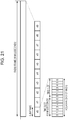
- Fig. 21 shows a radio frame configuration of a downlink of LTE. As shown in the drawing, the radio frame is hierarchized into three layers: a time slot layer, a sub-frame layer, and a radio frame layer in ascending order of time unit.
- a 0.5 millisecond time slot is composed of seven OFDM symbols (for normal unicast transmission) and becomes a demodulation processing unit upon reception on the user side (UE terminal).
- a 1 millisecond sub-frame is composed of two consecutive time slots (fourteen OFDM symbols) and becomes a transmission time unit of one data packet subjected to correction encoding.
- a 10 millisecond radio frame is composed of ten consecutive sub-frames (that is, twenty time slots) and becomes a basic unit for multiplexing of all physical channels.
- the sub-frame is divided into a control region PDCCH that is used as a control signal from an eNodeB and a data region PDSCH that is used as user data.
- RB radio resource allocation
- a scheduler installed in a base station (eNodeB) allocates radio resources to respective users in units of resource blocks.
- up to three OFDM symbols starting from the head of a sub-frame are used as a control channel, that is, PDCCH.
- the scheduler of a base station can allocate resource blocks for each sub-frame, that is, at intervals of 1 millisecond. Position information of resource blocks is called scheduling. Scheduling information of uplinks and that of downlinks are both written into a control channel of the downlink.
- Each of the users can recognize resource blocks allocated to the user by viewing the control channel.
- the 0.5 millisecond time slot is a minimum allocation unit that can be used by each user.
- a scheduler installed in a base station eNodeB
- eNodeB allocates a time slot that may be used in units of time slots for each user.
- FDD and TDD can be selected.
- TDD it is possible to select which one of an uplink and a downlink to use for each sub-frame.
- CoMP When CoMP is applied to a LTE-based data communication system, it is important to constitute a CoMP set with a minimum necessary number of eNodeBs satisfying necessary quality for a UE terminal.
- updating the point selection it is necessary to consider a reduction in throughput due to the occupancy of a communication sequence by reference signals in the system, an increase in uplink overhead due to feedback of reference signal measurement results from the UE terminal to the eNodeB, and an increase in power consumption of the UE terminal associated with the measurement of the reference signals and the feedback on the measurement results.
- Examples of the reference signal that can be used in the measurement of communication quality of the eNodeB on the UE terminal side and is transmitted from the eNodeB include CRS, CSI-RS, and SRS.
- the measurement of these reference signals can be used for a variety of purposes.
- a first purpose is to search an eNodeB of a handover destination by a UE terminal. When quality of a serving eNodeB deteriorates, the UE terminal performs measurement on eNodeBs of adjacent cells in order to search an eNodeB of the next handover destination.
- a second purpose is to acquire channel quality.
- the measurement of reference signals is performed in order to determine a value of precoding used on the eNodeB side upon downlink transmission (a weighting factor of an antenna for performing beam forming), and to assign radio resources to the respective UE terminals by the schedulers of the eNodeBs. Obtaining information necessary for point selection is added as a new object of the measurement of reference signals.
- a cell-specific reference signal is a reference signal that is inserted into a downlink sub-frame, and exists from Release 8, that is an initial version of LTE.
- Fig. 22 shows an aspect in which CRSs are inserted into a sub-frame.
- up to three OFDM symbols starting from the head serve as a PDCCH, and the fourth and subsequent OFDM symbols serve as a PDSCH.
- resource element parts painted out in black correspond to CRSs, and the CRSs are inserted into both the PDCCH and PDSCH regions.
- the CRS is transmitted from an eNodeB even when being not transmitted from user data or an eNodeB of the PDSCH. This is because it is assumed that the UE terminal always uses the CRS to acquire synchronization between the UE terminal and the eNodeB, to perform channel estimation, and to measure the quality of the eNodeB.
- the CRS uses the same place in each eNodeB (that is, a resource element having the same frequency and the same time direction) (in Fig. 22 , a resource element painted out in black is commonly used as a CRS insertion place in each eNodeB). Therefore, it is necessary to secure orthogonality between the eNodeBs, and a signal that is different in sequence is used as a CRS for each eNodeB. 504 sequences exist in total. When the eNodeBs have different cell IDs, these are also different in CRS sequence.
- the CRS called a cell-specific reference signal, means that it is unique for each cell.
- a channel state information reference signal is a reference signal that is included in a downlink signal. It is not included in all the sub-frames, but inserted every certain cycle. For example, a CSI-RS can be set to be transmitted once per 5 to 80 milliseconds in one sub-frame. The setting of the cycle can be semi-statically updated through radio resource control (RRC) signaling.
- RRC radio resource control
- the CSI-RS is a reference signal that is newly introduced in Release 10 of 3GPP.
- the CSI-RS is a reference signal added for this.
- the UE terminal can be notified of a place to be used to transmit a CSI-RS (reference signal) through dedicated signaling for every eNodeB.
- the CSI-RS is also a unique signal for each cell, and can be called a cell-specific signal.
- the position of a resource element in which a CSI-RS is inserted into a sub-frame can also be changed by setting.
- a sequence for improving orthogonality between the eNodeBs is also provided for a signal to be inserted.
- the CSI-RS is used as a reference signal for point selection. Since the transmission cycle can be set in a range of 5 to 80 milliseconds as described above, the CSI-RS is greatly advantageous in that the overhead occupied by reference signals can be reduced. In addition, even when the eNodeBs have the same cell ID, the CSI-RS can be allocated to a different place. As in a case in which CoMP is realized through an integrated control method, even when the same cell ID is allocated to plural pico eNodeBs such as RRHs, the UE terminal can perform measurement by distinguishing the respective RRHs when CSI-RSs are separately set. Accordingly, the inventors of the invention think that the CSI-RS is desirable as a reference signal for point selection.
- a sounding reference signal is a reference signal that is included in an uplink sub-frame, and exists from Release 8 of 3GPP.
- the SRS is inserted over the entire frequency region of the final one among fourteen OFDM symbols in a corresponding sub-frame.
- the SRS insertion cycle can be changed in a range of 2 to 160 milliseconds.
- the eNodeB acquires an uplink channel state based on the SRS, and uses the acquired state as information for scheduling.
- the SRS When using the SRS, it is possible to acquire an uplink channel situation with small overhead. When TDD is applied, channel reversibility is secured. Whereby, in the case of TDD, the SRS can be used in order to acquire a downlink channel situation by the eNodeB.
- scenarios 1 to 4 there are scenarios 1 to 4 as scenarios for realizing CoMP.
- cells are sectorized to perform the CoMP between sectors.
- the CoMP is used using RRHs.
- the RRHs perform transmission with the same high power as a macro eNodeB
- the transmission power of the RRHs is small.
- a unique cell ID is allocated for each RRH
- the same cell ID as the macro eNodeB is allocated to each RRH.
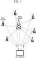
- Fig. 1 schematically shows a form of connection of a macro eNodeB and plural RRHs subordinate thereto, corresponding to the scenarios 3 and 4.
- the RHHs are arranged at cell edges and the like as a measure for non-sensing.
- the macro eNodeB and the respective RHHs (or pico eNodeBs) are connected by baseband signals using an X2 interface composed of an optical fiber and the like.
- the macro eNodeB performs baseband signal processing and control of the respective RRHs to perform collective radio resource control between the cells.
- the macro eNodeB and the RRHs simultaneously transmit and receive data to a UE terminal to perform CoMP.
- a reference signal that is used in point selection in the system shown in Fig. 1 will be considered.
- the respective RRHs have a unique cell ID, and are also different in CRS sequence. Accordingly, even when reference signals are simultaneously transmitted from the respective RRHs, the UE terminal can individually acquire quality for each RRH. That is, in the scenario 3, a CRS can be used as a reference signal for point selection.
- the respective RRHs have the same cell ID as the macro eNodeB allocated thereto, and are also the same in CRS sequence. Therefore, the UE terminal cannot individually acquire quality for each RRH from the CRSs simultaneously transmitted from the respective RRHs. That is, in the scenario 4, it is difficult to use a CRS as a reference signal for point selection. Therefore, in the scenario 4, a CSI-RS is expected as a reference signal for point selection. In that case, it is necessary to allocate a CSI-RS to a different place for each RRH to individually acquire channel information for each RRH on the UE terminal side (as described above, even when the eNodeBs have the same cell ID, a CSI-RS can be allocated to a different place).
- the UE terminal can frequently measure the quality of each eNodeB using the CRSs and a frequency of changing the CoMP set is increased.
- the macro eNodeB and the respective RRHs connected thereto have the same cell ID and transmit the same CRS, individual measurement for each eNode cannot be performed based on the CRS. That is, in the scenario 4, it is difficult to use a CRS as a reference signal for point selection.
- a CSI-RS can be used as a reference signal for point selection in the scenario 4.
- the measurement frequency is reduced, and thus a point selection update frequency is reduced.
- a first problem occurs in that when the CSI-RS transmission cycle is reduced, the measurement frequency is improved, but the throughput is reduced.
- the UE terminal uses a CSI-RS as a reference signal for point selection only in the case of the scenario 4, and uses a CRS as a reference signal for point selection in the cases of the scenarios 1 to 3 other than the scenario 4.
- the UE terminal wants to judge which one of a CSI-RS and a CRS is to be used as a reference signal for point selection, in accordance with whether a cell where the UE terminal currently exists is related to the scenario 4 or the scenarios 1 to 3. However, the UE terminal does not grasp whether the cell where the UE terminal currently exists is related to the scenario 4 or the scenarios 1 to 3. Accordingly, a method of designating performing CSI-RS measurement with respect to a UE terminal by an eNodeB, or a method of designating the application of the scenario 4 with respect to a UE terminal by an eNodeB is considered.
- CSI-RSs exist and there is a possibility that whether the applied scenario is the scenario 3 or the scenario 4 may be changed for each UE terminal. Accordingly, means for issuing an explicit instruction to the UE terminal from the eNodeB is provided. Specifically, through RRC signaling, the eNodeB notifies the UE terminal of the fact that the measurement of a specific cell ID will be performed using a CSI-RS (that is, a cell ID using a CSI-RS as a reference signal for point selection).
- Fig. 2 shows an example of a communication sequence in which point selection is performed using a CSI-RS only in the scenario 4.
- the eNodeB Upon measurement for point selection, the eNodeB issues an instruction to the UE terminal through RRC signaling to perform measurement for point selection using a CSI-RS (not CRS) with regard to designated cell IDs to thus perform feedback (M201).
- a CSI-RS not CRS
- the UE terminal performs the measurement for point selection (P201). However, in accordance with the above-described instruction, the measurement is performed with a CSI-RS with regard to the designated cell IDs, whereas for cell IDs not designated, the measurement is performed with a CRS.
- the UE terminal provides feedback to the eNodeB about the results of the measurement of the CRS or the CSI-RS from the eNodeB of each of the cell IDs (M202).
- the eNodeB performs point selection based on the feedback information from the UE terminal, and determines a CoMP set for the UE terminal (P202).
- the CSI-RS transmission cycle or transmission frequency is controlled in accordance with the number of UE terminals requiring CoMP.
- the CSI-RS transmission cycle when the CSI-RS transmission cycle is lengthened, the overhead is reduced and the power consumption on the eNodeB side is also reduced.
- the CSI-RS transmission cycle may be lengthened based on the thought that when the number of UE terminals requiring CoMP is small, the point selection update frequency may be reduced.
- the CSI-RS transmission cycle when the CSI-RS transmission cycle is shortened, the point selection update frequency is improved, and thus an unnecessary eNodeB can be promptly eliminated from the CoMP set and the radiation of unnecessary radio waves to the neighborhood can be reduced.
- the CSI-RS transmission cycle may be shortened based on the thought that when the number of UE terminals requiring CoMP is small, the load on the eNodeBs that perform the point selection is small.
- means for grasping the number of UE terminals requiring CoMP and means for controlling the CSI-RS transmission cycle based on the number of UE terminals requiring CoMP are provided on the eNodeB side.
- the UE terminals requiring CoMP are considered as UE terminals existing at cell edges. Therefore, the eNodeBs can estimate the number of UE terminals requiring CoMP, based on a timing advantage value and the number of UE terminals that are judged to be arranged in the distance by the power control.
- Fig. 3 shows processing procedures for controlling the CSI-RS transmission cycle based on the number of UE terminals requiring CoMP in a flowchart format.
- Step S301 when each RRH grasps the number of UE terminals existing at cell edges based on a timing advantage value and power control, the macro eNodeB is notified of the grasped information (Step S301).
- the macro eNodeB determines a CSI-RS transmission cycle necessary for each RRH based on the number of terminals (Step S303), and each RRH is notified of the determined information.
- Each RRH transmits a CSI-RS with the transmission cycle determined by the macro eNodeB (Step S304).
- the point selection update frequency is improved using both of an SRS and a CSI-RS as a reference signal for point selection.
- the SRS is a reference signal that is included in an uplink sub-frame (described above).
- TDD time division duplex
- channel reversibility is secured.
- the eNodeB can use the SRS in order to acquire a downlink channel situation.
- Fig. 4 shows an example of a communication sequence in which measurement for point selection is performed using both of an SRS and a CSI-RS. TDD is applied in the cell.
- a CSI-RS is transmitted from the eNodeB with a predetermined transmission cycle.
- the UE terminal performs measurement for point selection using the CSI-RS, and the eNodeB is notified of the results of the measurement.
- the eNodeB uses an SRS included in a sub-frame of an uplink from the UE terminal to perform measurement for point selection.
- the radio frame of the uplink from the UE terminal is not particularly limited.
- the UE terminal can use an SRS included in a radio frame that feeds the results of the measurement for point selection back.
- the eNodeB performs point selection based on the results of the measurement fed back from the UE terminal and the results of the measurement performed in the eNodeB, and determines a CoMP set for this UE terminal. Since the measurement for updating the point selection is dispersed to both of the UE terminal and the eNodeB, the measurement load on the UE terminal is reduced. Thereafter, data transmission and reception with the UE terminal is performed by the CoMP set that reflects the results of the point selection.
- downlink channel quality can be specified from an SRS of an uplink. Accordingly, as shown in Fig. 4 , using s SRS and a CSI-RS in combination for dynamic point selection, downlink overhead is reduced, and a load on the measurement of the UE terminal can be suppressed.
- a CSI-RS transmission frequency is increased in order to improve the point selection update frequency, only downlink overhead increases.
- an SRS and a CSI-RS are used in combination, overhead that is applied to the uplink and the downlink can be equalized.
- the means 2-2 is effective only in a transmission mode of the TDD.
- a third problem occurs in that when the UE terminal meaninglessly performs measurement for point selection, the power consumption is uselessly increased.
- the UE terminal performs measurement by receiving a reference signal only when the moving speed of the UE terminal is high, and thus the point selection update frequency should be improved.
- the UE terminal does not receive all of CSI-RSs transmitted with a predetermined cycle from the eNodeBs to perform the measurement.
- the UE terminal determines a necessary measurement cycle in accordance with a moving speed of the UE terminal to selectively receive CSI-RSs, and feeds the results of the measurement thereof back to the eNodeBs to perform the point selection.
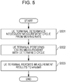
- Fig. 5 shows processing procedures for feeding measurement results back to the eNodeBs by the UE terminal with a measurement cycle according to the moving speed of the UE terminal in a flowchart format.
- the UE terminal determines a necessary reference signal measurement cycle based on the moving speed of the UE terminal (Step S501).
- the UE terminal Based on the determined measurement cycle, the UE terminal performs measurement of reference signals such as CSI-RSs transmitted with a predetermined cycle from the eNodeBs (Step S502), and feeds the results of the measurement back to the eNodeBs (Step S503).
- reference signals such as CSI-RSs transmitted with a predetermined cycle from the eNodeBs
- Fig. 6 shows an example of a communication sequence in which the eNodeB transmits a CSI-RS with a predetermined transmission cycle, whereas the UE terminal receives a CSI-RS with a measurement cycle set by the UE terminal.
- a CSI-RS is transmitted with a transmission cycle for, for example, realizing dynamic point selection with an update frequency desired by an operator.
- the UE terminal selectively measures CSI-RSs with a uniquely set measurement cycle.
- the UE terminal can set the measurement cycle in accordance with the moving speed of the UE terminal as described above. However, the measurement cycle may be set in consideration of other situations.
- the UE terminal since the UE terminal performs selective measurement with a CSI-RS cycle to omit unnecessary measurement, it is possible to reduce the power consumption of the UE terminal.
- the reference signal measurement frequency is controlled according to the quality in the CoMP set.
- the means 3-2 can be used in a scenario in which an unnecessary eNodeB is eliminated from the CoMP set.
- the UE terminal raises the reference signal measurement frequency.
- the UE terminal selectively measures CSI-RSs transmitted with a predetermined cycle from the respective eNodeBs included in the CoMP set with a measurement cycle set by the UE terminal (that is longer than the transmission cycle).
- the measurement cycle is reduced only for the eNodeB so that the measurement is frequently performed.
- the means 3-2 is similar to the means 3-1 in that the UE terminal omits unnecessary measurement.
- the reference signal measurement is started with a deterioration in quality of a serving eNodeB as a trigger.
- the reference signal measurement is performed, but the measurement frequency is raised for one exhibiting a large deterioration in quality among the eNodeBs included in the CoMP set.
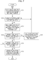
- Fig. 7 shows processing procedures for eliminating an eNodeB exhibiting a large deterioration in quality from the CoMP set by controlling the reference signal measurement frequency in a flowchart format.
- a threshold 1 for judging whether to raise the measurement frequency and a threshold 2 for judging whether to perform elimination from the CoMP set are used as quality deterioration thresholds.
- the UE terminal performs measurement with a measurement cycle set for each eNodeB by using CSI-RSs from the eNodeBs belonging to the CoMP set (Step S701).
- Step S703 when a fact that the quality of a specific eNodeB among the eNodeBs of the CoMP set is less than the quality deterioration threshold 1 is detected (Yes in Step S702), the UE terminal performs the measurement with a CSI-RS measurement frequency raised with regard to the eNodeB (Step S703).
- Step S704 the UE terminal performs the measurement with a CSI-RS measurement frequency reduced with regard to the eNodeB (Step S707).
- Step S705 when a fact that the quality of the eNodeB that was less than the threshold 1 is not recovered and further less than the quality deterioration threshold 2 is detected (Yes in Step S705), the serving eNodeB receiving such a measurement result performs dynamic point selection to eliminate the eNodeB of which the quality is less than the threshold 2 from the CoMP set (Step S706).
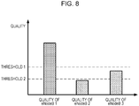
- Fig. 8 schematically shows the results of the measurement of the quality of each eNodeB by the UE terminal.
- the UE terminal performs CSI-RS measurement on eNodeBs #1 to #3. Since the quality of the eNodeB#1 is greater than the threshold 1, the measurement frequency is not raised. In addition, since the quality of the eNodeB#2 is less than the threshold 2, the eNodeB#2 is eliminated from the CoMP set through dynamic point selection. In addition, since the quality of the eNodeB#3 is less than the threshold 1, but greater than the threshold 2, the measurement is performed with the raised measurement frequency.
- the means 3-2 can also be used in a scenario in which an eNodeB to be newly added to the CoMP set is searched.
- the quality of a specific eNodeB does not deteriorate, but when the quality is not maintained as a whole with receiving power of the eNodeBs included in the current CoMP set, it is necessary to search an eNodeB that is expected to have higher receiving power, and thus the measurement frequency is raised.
- Fig. 9 shows processing procedures for searching an eNodeB to be newly added to the CoMP set by controlling the reference signal measurement frequency in a flowchart format.
- the UE terminal performs measurement with a CSI-RS corresponding to a new eNodeB while performing measurement for point selection using CSI-RSs corresponding to the respective eNodeBs included in the CoMP set (Step S901).
- Step S903 when receiving quality of the UE terminal performing the CoMP is equal to or less than a predetermined threshold (Yes in Step S902), the UE terminal increases the measurement frequency for the new eNodeB (Step S903).
- Step S904 when the receiving quality of the UE terminal performing the CoMP exceeds a predetermined threshold (No in Step S902), the UE terminal reduces the measurement frequency for the new eNodeB (Step S904).
- the frequency of measuring a reference signal for point selection is controlled on the eNodeB side, or the frequency of measuring a reference signal is controlled on the UE terminal side in accordance with the number of base stations existing in an area to which the UE terminal is moved.
- the cycle of CSI-RS transmission from the eNodeB is reduced, and the measurement frequency is raised on the UE terminal side.
- the cycle of CSI-RS transmission from the eNodeB is lengthened, and the measurement frequency is reduced on the UE terminal side.
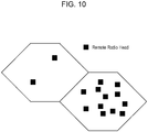
- Fig. 10 shows an example of distribution of RRHs existing in cells.
- RRHs that is, base stations for performing CoMP as in the cell shown on the right side of Fig. 10
- RRHs necessary for performing CoMP are changed even with a small movement of the UE terminal. Therefore, it is necessary to improve the point selection update frequency, and the measurement frequency is raised on the UE terminal side.
- the number of RRHs that is, base stations for performing CoMP is small as in the cell shown on the left side of Fig. 10
- base stations necessary for performing CoMP are rarely changed with a movement of the UE terminal, and thus it is not necessary to raise the point selection update frequency.
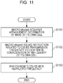
- Fig. 11 shows processing procedures for controlling a frequency of transmitting a CSI-RS from the eNodeB in accordance with RRH density in a flowchart format.
- the macro eNodeB acquires arrangement information of RRHs in its own cell (Step S1101).
- the macro eNodeB issues an instruction related to the CSI-RS transmission frequency to each RRH in consideration of the RRH density in its own cell (Step S1102).
- the RRH transmits a CSI-RS with the transmission frequency instructed from the macro eNodeB (Step S1103).
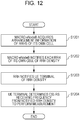
- Fig. 12 shows processing procedures for controlling a frequency of receiving a CSI-RS from the eNodeB by the UE terminal in accordance with RRH density in a flowchart format.
- Step S1201 When acquiring arrangement information of RRHs in its own cell (Step S1201), the macro eNodeB notifies each RRH in its own cell of RRH density (Step S1202).
- Each RRH further notifies the UE terminal of the notified RRH density (Step S1203).
- the UE terminal determines a frequency of receiving a CSI-RS based on the notified RRH density to perform measurement for point selection (Step S1204).
- a carrier aggregation technology is introduced to LTE.
- the channel is different for each component carrier, and thus it is assumed that the respective component carriers are totally different in CoMP application situation. That is, whether CoMP is applied is different for each component carrier, and the configuration of eNodeBs included in a CoMP set is also different even when the CoMP is applied.
- a fourth problem occurs in that when the measurement frequency for point selection is uniform in the respective component carriers, wastefulness occurs.
- the frequency of transmitting a CSI-RS is controlled in accordance with a degree of CoMP recommendation with respect to each component carrier. That is, in the means 4-1, in the case of a component carrier recommending CoMP, the frequency of transmitting a CSI-RS is increased.
- one primary carrier is referred to as “primary carrier”, and one or more other carriers are referred to as “secondary carriers”.
- primary carrier is referred to as “primary carrier”
- secondary carriers are utilized as component carriers specialized for CoMP (see Fig. 13 ).
- the CSI-RS transmission frequency of the secondary component carriers, rather than the primary component carrier, is increased.
- the frequency of transmitting a CSI-RS is controlled in accordance with a change in the channels of the component carriers.
- a component carrier of high frequency has a larger channel change than a component carrier of low frequency. Accordingly, in the component carrier of high frequency, a higher CSI-RS transmission frequency is set than in the component carrier of low frequency (see Fig. 14 ).
- component carriers adjacent to each other on the frequency axis share reference signal measurement results to reduce the frequency of transmitting a CSI-RS over the entire system.
- component carriers that are consecutively arranged on the frequency axis, or component carriers that are arranged adjacent to each other may have remarkably similar channel information. In many cases, at least the quality of the entire eNodeBs is sufficient when measured in any one of the component carriers.
- the component carrier 1 and the component carrier 2 are adjacent to each other on the frequency axis, as shown in Fig. 15 , only the component carrier 1 transmits CSI-RSs, the other component carrier 2 transmits no CSI-RSs, and the measurement results in the component carrier 2 are used.
- the component carrier 1 and the component carrier 2 may share the transmission of CSI-RSs so that the CSI-RSs do not overlap on the time axis and the frequency axis.
- the CSI-RS transmission cycle of the RRH is controlled in accordance with a usage situation in the CoMP set.
- RRHs or eNodeBs belonging to the same CoMP set can be divided into RRHs that are normally included in the CoMP set and RRHs that are rarely included in the CoMP set by measurement by the UE terminal.
- the CSI-RSs of the RRHs that are normally used by the CoMP should be transmitted with a short cycle, and the CSI-RSs of the eNodeBs that are rarely used in the CoMP should be transmitted with a long cycle.
- the serving eNodeB may count the number of UE terminals that are in a radio link control-connected (that is, RRC-connected) state with the respective RRHs to set a CSI-RS transmission frequency for each RRH in accordance with the number of UE terminals that are in a radio link control-connected state.
- a radio link control-connected that is, RRC-connected
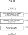
- Fig. 17 shows processing procedures for controlling the CSI-RS transmission cycle of the RRH in accordance with a usage situation in the CoMP set in a flowchart format.
- the macro eNodeB acquires the number of UE terminals that are in a radio link control-connected (that is, RRC-connected) state (Step S1701).
- the macro eNodeB When the CSI-RS transmission frequency is set for each RRH in accordance with the number of UE terminals that are in a radio link control-connected state (Step S1702), the macro eNodeB notifies each RRH of the set CSI-RS transmission frequency (Step S1703).
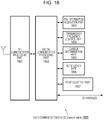
- Fig. 18 schematically shows an example of a configuration of a radio communication device 1800 that is operated as a macro eNodeB in the radio communication system ( Fig. 1 ) according to this exemplary embodiment.
- functional modules that perform basic operations as a macro eNodeB such as radio resource management in the macro cell, transmission of various reference signals, RRC signaling to the UE terminal, and measurement of a reference signal SRS included in a radio frame of an uplink from the UE terminal, are appropriately omitted.
- the radio communication device 1800 is provided with a RF communication processing part 1801 that performs analog processing of radio signals that are transmitted and received by an antenna and a digital communication processing part 1802 that performs modulation processing of digital transmission signals and demodulation processing of digital reception signals.
- the digital communication processing part 1802 exchanges transmission and reception data with an upper layer protocol of a communication layer of the device 1800.
- the digital communication processing part 1802 communicates with other eNodeBs through an X2 interface, a serving gateway (S-GW), and a mobility management entity (MME).
- S-GW serving gateway
- MME mobility management entity
- the digital communication processing part 1802 performs baseband signal processing and control of the respective RRHs subordinate to the device 1800 through the X2 interface.
- a RRH information acquisition part 1803 acquires, from each RRH, information related to the RRH subordinate to the device 1800 using the X2 interface such as an optical fiber.
- the RRH information acquisition part 1803 acquires, from each RRH, information necessary for realizing the above-described means 2-1, 3-3, and 6. Examples of the acquired information include the number of UE terminals that are in a radio link control-connected (that is, RRC-connected) state with the RRHs, and the RRH density in its own cell.
- a transmission frequency control part 1804 controls the CSI-RS transmission frequency of each RRH subordinate to the device 1800.
- the transmission frequency control part 1804 functions as any of the above-described means 2-1, 2-2, 3-3, 4-1, 4-2, 4-3, and 5.
- a carrier determination part 1805 determines the importance of performing CoMP for each component carrier upon carrier aggregation.
- the carrier determination part 1805 performs determination for judging a component carrier that will use CoMP (or that are recommended to use CoMP) in the realization of the above-described means 5-1.
- a notification part 1806 notifies each pico eNodeB (including RRH) subordinate to the device 1800 of the CSI-RS transmission frequency determined by the transmission frequency control part 1804. If necessary, the notification part 1806 notifies the UE terminal belonging to the pico eNodeB of the CSI-RS measurement frequency and the like. In the realization of the above-described means 2-1, 3-3, 4-1, 4-2, 4-3, and 5, the notification part 1806 performs notification to the corresponding pico eNodeB. In addition, in the realization of the above-described means 1 and 3-3, the notification part 1806 performs necessary notification to the UE terminal.
- the radio communication device 1800 can acquire results of the CSI-RS measurement, that is, feedback for point selection from the UE terminal with desired frequency.
- a point selection part 1807 configures a CoMP set with a minimum necessary number of eNodeBs satisfying necessary quality for the UE terminal based on the feedback information.
- the point selection part 1807 performs point selection based on both of the feedback information from the UE terminal and results of the measurement of SRSs included in an uplink from the UE terminal to realize the above-described means 2-2.
- Fig. 19 schematically shows an example of a configuration of a radio communication device 1900 that is operated as a pico eNodeB or a RRH in the radio communication system ( Fig. 1 ) according to this exemplary embodiment.
- functional modules that perform basic operations as a pico eNodeB, such as radio resource management in the pico cell and RRC signaling to the UE terminal, are appropriately omitted.
- the radio communication device 1900 is provided with a RF communication processing part 1901 that performs analog processing of radio signals that are transmitted and received by an antenna and a digital communication processing part 1902 that performs modulation processing of digital transmission signals and demodulation processing of digital reception signals.
- the digital communication processing part 1902 exchanges transmission and reception data with an upper layer protocol of a communication layer of the device 1900.
- the digital communication processing part 1902 communicates with other eNodeBs through an X2 interface, a serving gateway (S-GW), and a mobility management entity (MME).
- S-GW serving gateway
- MME mobility management entity
- a transmission frequency control part 1903 controls a frequency of transmitting a CSI-RS from the device 1900.
- the transmission frequency control part 1903 contributes to the realization of the above described means 2-1, 2-2, 3-3, 4-1, 4-2, 4-3, and 4 by determining a CSI-RS transmission frequency in accordance with a notification from a macro eNodeB (serving macro eNodeB) to which the device 1900 is subordinate.
- a measurement frequency notification part 1904 contributes to the realization of the above-described means 1 and 3-3 by issuing an instruction related to the CSI-RS measurement frequency to the UE terminal belonging to the device 1900 in response to the CSI-RS transmission frequency determined by the transmission frequency control part 1903.
- a setting information acquisition part 1905 acquires, through the X2 interface, various information set by the serving eNodeB with respect to the device 1900, such as a frequency of transmitting a CSI-RS from the device 1900.
- Fig. 20 schematically shows an example of a configuration of a radio communication device 2000 that is operated as a UE terminal in the radio communication system ( Fig. 1 ) according to this exemplary embodiment.
- functional modules that perform basic operations as a UE terminal are appropriately omitted.
- the radio communication device 2000 is provided with a RF communication processing part 2001 that performs analog processing of radio signals that are transmitted and received by an antenna and a digital communication processing part 2002 that performs modulation processing of digital transmission signals and demodulation processing of digital reception signals.
- the digital communication processing part 2002 exchanges transmission and reception data with an upper layer protocol of a communication layer of the device 2000.
- a measurement frequency control part 2003 controls a frequency of measuring a reference signal for point selection such as a CSI-RS in the device 2000.
- the measurement frequency control part 2003 controls a frequency of measuring a CSI-RS in response to a moving speed of the device 2000, to realize the above-described means 3-1.
- the measurement frequency control part 2003 controls a frequency of measuring a CSI-RS from each eNode in a CoMP set based on communication quality, to realize the above-described means 3-2.
- the measurement frequency control part 2003 performs control so that a CRS is measured in the scenario 3 and a CSI-RS is measured in the scenario 4 for point selection, to realize the above-described means 1.
- a measurement frequency information acquisition part 2004 acquires information related to the setting of the CSI-RS measurement frequency from an eNodeB (serving pico eNodeB) to which the device 2000 belongs. In addition, the measurement frequency information acquisition part 2004 acquires, as information related to the measurement frequency, information for identifying a scenario that is applied in the cell. The CSI-RS measurement is performed in accordance with the measurement frequency acquired by the measurement frequency information acquisition part 2004 to contribute to the realization of the above-described means 1 and 3-3.
- a reference signal measurement part 2005 performs measurement of a reference signal for point selection such as a CSI-RS, based on the measurement frequency determined by the measurement frequency control part 2003 or the measurement frequency acquired by the measurement frequency information acquisition part 2004.
- the reference signal measurement part 2005 realizes the above-described means 1 by reference signal switching in which measurement for point selection is performed using a CRS in the scenario 3 and is performed using a CSI-RS in the scenario 4.
- the results of the measurement by the reference signal measurement part 2005 are transmitted to the serving pico eNodeB through the digital communication processing part 2002 and the RF communication processing part 2001.
- the description has focused on the exemplary embodiments applied to a cellular communication system according to LTE designed by 3GPP, but the gist of the technology disclosed in the present specification is not limited thereto.
- the technology disclosed in the present specification can similarly be applied to various cellular communication systems to which a technology for simultaneously transmitting and receiving data to a terminal by cooperation of plural base stations is applied.
- the means 3-2 can be used in a scenario in which an unnecessary eNodeB is eliminated from the CoMP set.
- the UE terminal raises the reference signal measurement frequency.
- the UE terminal selectively measures CSI-RSs transmitted with a predetermined cycle from the respective eNodeBs included in the CoMP set with a measurement cycle set by the UE terminal (that is longer than the transmission cycle).
- the measurement cycle is reduced only for the eNodeB so that the measurement is frequently performed.
- the means 3-2 is similar to the means 3-1 in that the UE terminal omits unnecessary measurement.
- the reference signal measurement is started with a deterioration in quality of a serving eNodeB as a trigger.
- the reference signal measurement is performed, but the measurement frequency is raised for one exhibiting a large deterioration in quality among the eNodeBs included in the CoMP set.
- Fig. 7 shows processing procedures for eliminating an eNodeB exhibiting a large deterioration in quality from the CoMP set by controlling the reference signal measurement frequency in a flowchart format.
- a threshold 1 for judging whether to raise the measurement frequency and a threshold 2 for judging whether to perform elimination from the CoMP set are used as quality deterioration thresholds.
- the UE terminal performs measurement with a measurement cycle set for each eNodeB by using CSI-RSs from the eNodeBs belonging to the CoMP set (Step S701).
- Step S703 when a fact that the quality of a specific eNodeB among the eNodeBs of the CoMP set is less than the quality deterioration threshold 1 is detected (Yes in Step S702), the UE terminal performs the measurement with a CSI-RS measurement frequency raised with regard to the eNodeB (Step S703).
- Step S704 the UE terminal performs the measurement with a CSI-RS measurement frequency reduced with regard to the eNodeB (Step S707).
- Step S705 when a fact that the quality of the eNodeB that was less than the threshold 1 is not recovered and further less than the quality deterioration threshold 2 is detected (Yes in Step S705), the serving eNodeB receiving such a measurement result performs dynamic point selection to eliminate the eNodeB of which the quality is less than the threshold 2 from the CoMP set (Step S706).
- Fig. 8 schematically shows the results of the measurement of the quality of each eNodeB by the UE terminal.
- the UE terminal performs CSI-RS measurement on eNodeBs #1 to #3. Since the quality of the eNodeB#1 is greater than the threshold 1, the measurement frequency is not raised. In addition, since the quality of the eNodeB#2 is less than the threshold 2, the eNodeB#2 is eliminated from the CoMP set through dynamic point selection. In addition, since the quality of the eNodeB#3 is less than the threshold 1, but greater than the threshold 2, the measurement is performed with the raised measurement frequency.
- the means 3-2 can also be used in a scenario in which an eNodeB to be newly added to the CoMP set is searched.
- the quality of a specific eNodeB does not deteriorate, but when the quality is not maintained as a whole with receiving power of the eNodeBs included in the current CoMP set, it is necessary to search an eNodeB that is expected to have higher receiving power, and thus the measurement frequency is raised.
- Fig. 9 shows processing procedures for searching an eNodeB to be newly added to the CoMP set by controlling the reference signal measurement frequency in a flowchart format.
- the UE terminal performs measurement with a CSI-RS corresponding to a new eNodeB while performing measurement for point selection using CSI-RSs corresponding to the respective eNodeBs included in the CoMP set (Step S901).
- Step S903 when receiving quality of the UE terminal performing the CoMP is equal to or less than a predetermined threshold (Yes in Step S902), the UE terminal increases the measurement frequency for the new eNodeB (Step S903).
- Step S904 when the receiving quality of the UE terminal performing the CoMP exceeds a predetermined threshold (No in Step S902), the UE terminal reduces the measurement frequency for the new eNodeB (Step S904).
- the frequency of measuring a reference signal for point selection is controlled on the eNodeB side, or the frequency of measuring a reference signal is controlled on the UE terminal side in accordance with the number of base stations existing in an area to which the UE terminal is moved.
- the cycle of CSI-RS transmission from the eNodeB is reduced, and the measurement frequency is raised on the UE terminal side.
- the cycle of CSI-RS transmission from the eNodeB is lengthened, and the measurement frequency is reduced on the UE terminal side.
- Fig. 10 shows an example of distribution of RRHs existing in cells.
- RRHs that is, base stations for performing CoMP as in the cell shown on the right side of Fig. 10
- RRHs necessary for performing CoMP are changed even with a small movement of the UE terminal. Therefore, it is necessary to improve the point selection update frequency, and the measurement frequency is raised on the UE terminal side.
- the number of RRHs that is, base stations for performing CoMP is small as in the cell shown on the left side of Fig. 10
- base stations necessary for performing CoMP are rarely changed with a movement of the UE terminal, and thus it is not necessary to raise the point selection update frequency.
- Fig. 11 shows processing procedures for controlling a frequency of transmitting a CSI-RS from the eNodeB in accordance with RRH density in a flowchart format.
- the macro eNodeB acquires arrangement information of RRHs in its own cell (Step S1101).
- the macro eNodeB issues an instruction related to the CSI-RS transmission frequency to each RRH in consideration of the RRH density in its own cell (Step S1102).
- the RRH transmits a CSI-RS with the transmission frequency instructed from the macro eNodeB (Step S1103).
- Fig. 12 shows processing procedures for controlling a frequency of receiving a CSI-RS from the eNodeB by the UE terminal in accordance with RRH density in a flowchart format.
- Step S1201 When acquiring arrangement information of RRHs in its own cell (Step S1201), the macro eNodeB notifies each RRH in its own cell of RRH density (Step S1202).
- Each RRH further notifies the UE terminal of the notified RRH density (Step S1203).
- the UE terminal determines a frequency of receiving a CSI-RS based on the notified RRH density to perform measurement for point selection (Step S1204).
- the channel is different for each component carrier, and thus it is assumed that the respective component carriers are totally different in CoMP application situation. That is, whether CoMP is applied is different for each component carrier, and the configuration of eNodeBs included in a CoMP set is also different even when the CoMP is applied.
- a fourth problem occurs in that when the measurement frequency for point selection is uniform in the respective component carriers, wastefulness occurs.
- the frequency of transmitting a CSI-RS is controlled in accordance with a degree of CoMP recommendation with respect to each component carrier. That is, in the means 4-1, in the case of a component carrier recommending CoMP, the frequency of transmitting a CSI-RS is increased.
- one primary carrier is referred to as “primary carrier”, and one or more other carriers are referred to as “secondary carriers”.
- primary carrier is referred to as “primary carrier”
- secondary carriers are utilized as component carriers specialized for CoMP (see Fig. 13 ).
- the CSI-RS transmission frequency of the secondary component carriers, rather than the primary component carrier, is increased.
- the frequency of transmitting a CSI-RS is controlled in accordance with a change in the channels of the component carriers.
- a component carrier of high frequency has a larger channel change than a component carrier of low frequency. Accordingly, in the component carrier of high frequency, a higher CSI-RS transmission frequency is set than in the component carrier of low frequency (see Fig. 14 ).
- component carriers adjacent to each other on the frequency axis share reference signal measurement results to reduce the frequency of transmitting a CSI-RS over the entire system.
- component carriers that are consecutively arranged on the frequency axis, or component carriers that are arranged adjacent to each other may have remarkably similar channel information. In many cases, at least the quality of the entire eNodeBs is sufficient when measured in any one of the component carriers.
- the component carrier 1 and the component carrier 2 are adjacent to each other on the frequency axis, as shown in Fig. 15 , only the component carrier 1 transmits CSI-RSs, the other component carrier 2 transmits no CSI-RSs, and the measurement results in the component carrier 2 are used.
- the component carrier 1 and the component carrier 2 may share the transmission of CSI-RSs so that the CSI-RSs do not overlap on the time axis and the frequency axis.
- the CSI-RS transmission cycle of the RRH is controlled in accordance with a usage situation in the CoMP set.
- RRHs or eNodeBs belonging to the same CoMP set can be divided into RRHs that are normally included in the CoMP set and RRHs that are rarely included in the CoMP set by measurement by the UE terminal.
- the CSI-RSs of the RRHs that are normally used by the CoMP should be transmitted with a short cycle, and the CSI-RSs of the eNodeBs that are rarely used in the CoMP should be transmitted with a long cycle.
- the serving eNodeB may count the number of UE terminals that are in a radio link control-connected (that is, RRC-connected) state with the respective RRHs to set a CSI-RS transmission frequency for each RRH in accordance with the number of UE terminals that are in a radio link control-connected state.
- a radio link control-connected that is, RRC-connected
- Fig. 17 shows processing procedures for controlling the CSI-RS transmission cycle of the RRH in accordance with a usage situation in the CoMP set in a flowchart format.
- the macro eNodeB acquires the number of UE terminals that are in a radio link control-connected (that is, RRC-connected) state (Step S1701).
- the macro eNodeB When the CSI-RS transmission frequency is set for each RRH in accordance with the number of UE terminals that are in a radio link control-connected state (Step S1702), the macro eNodeB notifies each RRH of the set CSI-RS transmission frequency (Step S1703).
- Fig. 18 schematically shows an example of a configuration of a radio communication device 1800 that is operated as a macro eNodeB in the radio communication system ( Fig. 1 ) according to this exemplary embodiment.
- functional modules that perform basic operations as a macro eNodeB such as radio resource management in the macro cell, transmission of various reference signals, RRC signaling to the UE terminal, and measurement of a reference signal SRS included in a radio frame of an uplink from the UE terminal, are appropriately omitted.
- the radio communication device 1800 is provided with a RF communication processing part 1801 that performs analog processing of radio signals that are transmitted and received by an antenna and a digital communication processing part 1802 that performs modulation processing of digital transmission signals and demodulation processing of digital reception signals.
- the digital communication processing part 1802 exchanges transmission and reception data with an upper layer protocol of a communication layer of the device 1800.
- the digital communication processing part 1802 communicates with other eNodeBs through an X2 interface, a serving gateway (S-GW), and a mobility management entity (MME).
- S-GW serving gateway
- MME mobility management entity
- the digital communication processing part 1802 performs baseband signal processing and control of the respective RRHs subordinate to the device 1800 through the X2 interface.
- a RRH information acquisition part 1803 acquires, from each RRH, information related to the RRH subordinate to the device 1800 using the X2 interface such as an optical fiber.
- the RRH information acquisition part 1803 acquires, from each RRH, information necessary for realizing the above-described means 2-1, 3-3, and 6. Examples of the acquired information include the number of UE terminals that are in a radio link control-connected (that is, RRC-connected) state with the RRHs, and the RRH density in its own cell.
- a transmission frequency control part 1804 controls the CSI-RS transmission frequency of each RRH subordinate to the device 1800.
- the transmission frequency control part 1804 functions as any of the above-described means 2-1, 2-2, 3-3, 4-1, 4-2, 4-3, and 5.
- a carrier determination part 1805 determines the importance of performing CoMP for each component carrier upon carrier aggregation.
- the carrier determination part 1805 performs determination for judging a component carrier that will use CoMP (or that are recommended to use CoMP) in the realization of the above-described means 5-1.
- a notification part 1806 notifies each pico eNodeB (including RRH) subordinate to the device 1800 of the CSI-RS transmission frequency determined by the transmission frequency control part 1804. If necessary, the notification part 1806 notifies the UE terminal belonging to the pico eNodeB of the CSI-RS measurement frequency and the like. In the realization of the above-described means 2-1, 3-3, 4-1, 4-2, 4-3, and 5, the notification part 1806 performs notification to the corresponding pico eNodeB. In addition, in the realization of the above-described means 1 and 3-3, the notification part 1806 performs necessary notification to the UE terminal.
- the radio communication device 1800 can acquire results of the CSI-RS measurement, that is, feedback for point selection from the UE terminal with desired frequency.
- a point selection part 1807 configures a CoMP set with a minimum necessary number of eNodeBs satisfying necessary quality for the UE terminal based on the feedback information.
- the point selection part 1807 performs point selection based on both of the feedback information from the UE terminal and results of the measurement of SRSs included in an uplink from the UE terminal to realize the above-described means 2-2.
- Fig. 19 schematically shows an example of a configuration of a radio communication device 1900 that is operated as a pico eNodeB or a RRH in the radio communication system ( Fig. 1 ) according to this exemplary embodiment.
- functional modules that perform basic operations as a pico eNodeB, such as radio resource management in the pico cell and RRC signaling to the UE terminal, are appropriately omitted.
- the radio communication device 1900 is provided with a RF communication processing part 1901 that performs analog processing of radio signals that are transmitted and received by an antenna and a digital communication processing part 1902 that performs modulation processing of digital transmission signals and demodulation processing of digital reception signals.
- the digital communication processing part 1902 exchanges transmission and reception data with an upper layer protocol of a communication layer of the device 1900.
- the digital communication processing part 1902 communicates with other eNodeBs through an X2 interface, a serving gateway (S-GW), and a mobility management entity (MME).
- S-GW serving gateway
- MME mobility management entity
- a transmission frequency control part 1903 controls a frequency of transmitting a CSI-RS from the device 1900.
- the transmission frequency control part 1903 contributes to the realization of the above described means 2-1, 2-2, 3-3, 4-1, 4-2, 4-3, and 4 by determining a CSI-RS transmission frequency in accordance with a notification from a macro eNodeB (serving macro eNodeB) to which the device 1900 is subordinate.
- a measurement frequency notification part 1904 contributes to the realization of the above-described means 1 and 3-3 by issuing an instruction related to the CSI-RS measurement frequency to the UE terminal belonging to the device 1900 in response to the CSI-RS transmission frequency determined by the transmission frequency control part 1903.
- a setting information acquisition part 1905 acquires, through the X2 interface, various information set by the serving eNodeB with respect to the device 1900, such as a frequency of transmitting a CSI-RS from the device 1900.
- Fig. 20 schematically shows an example of a configuration of a radio communication device 2000 that is operated as a UE terminal in the radio communication system ( Fig. 1 ) according to this exemplary embodiment.
- functional modules that perform basic operations as a UE terminal are appropriately omitted.
- the radio communication device 2000 is provided with a RF communication processing part 2001 that performs analog processing of radio signals that are transmitted and received by an antenna and a digital communication processing part 2002 that performs modulation processing of digital transmission signals and demodulation processing of digital reception signals.
- the digital communication processing part 2002 exchanges transmission and reception data with an upper layer protocol of a communication layer of the device 2000.
- a measurement frequency control part 2003 controls a frequency of measuring a reference signal for point selection such as a CSI-RS in the device 2000.
- the measurement frequency control part 2003 controls a frequency of measuring a CSI-RS in response to a moving speed of the device 2000, to realize the above-described means 3-1.
- the measurement frequency control part 2003 controls a frequency of measuring a CSI-RS from each eNode in a CoMP set based on communication quality, to realize the above-described means 3-2.
- the measurement frequency control part 2003 performs control so that a CRS is measured in the scenario 3 and a CSI-RS is measured in the scenario 4 for point selection, to realize the above-described means 1.
- a measurement frequency information acquisition part 2004 acquires information related to the setting of the CSI-RS measurement frequency from an eNodeB (serving pico eNodeB) to which the device 2000 belongs. In addition, the measurement frequency information acquisition part 2004 acquires, as information related to the measurement frequency, information for identifying a scenario that is applied in the cell. The CSI-RS measurement is performed in accordance with the measurement frequency acquired by the measurement frequency information acquisition part 2004 to contribute to the realization of the above-described means 1 and 3-3.
- a reference signal measurement part 2005 performs measurement of a reference signal for point selection such as a CSI-RS, based on the measurement frequency determined by the measurement frequency control part 2003 or the measurement frequency acquired by the measurement frequency information acquisition part 2004.
- the reference signal measurement part 2005 realizes the above-described means 1 by reference signal switching in which measurement for point selection is performed using a CRS in the scenario 3 and is performed using a CSI-RS in the scenario 4.
- the results of the measurement by the reference signal measurement part 2005 are transmitted to the serving pico eNodeB through the digital communication processing part 2002 and the RF communication processing part 2001.
- the description has focused on the exemplary embodiments applied to a cellular communication system according to LTE designed by 3GPP, but the gist of the technology disclosed in the present specification is not limited thereto.
- the technology disclosed in the present specification can similarly be applied to various cellular communication systems to which a technology for simultaneously transmitting and receiving data to a terminal by cooperation of plural base stations is applied.
Description
- The technology disclosed in the present specification relates to a radio communication device, a radio communication method, and a radio communication system adapted to simultaneously transmit and receive data to a terminal in cooperation with another base station, and particularly, to a radio communication device, a radio communication method, and a radio communication system adapted to determine a combination of base stations with respect to a terminal based on feedback from the terminal receiving a reference signal.
- Currently, standardization of fourth-generation mobile communication systems is performed in third generation partnership project (3GPP). "Long term evolution (LTE)", that is one of data communication specifications designed by 3GPP, is a long term advanced system aiming for the fourth generation (4G) IMT-Advanced, and is called "3.9G (super 3G)."
- In LTE, two duplex systems, i.e., frequency division duplex (FDD) and time division duplex (TDD) can be selected. In the FDD, an uplink-dedicated band and a downlink-dedicated band are used. In the uplink and the downlink, a format of a radio frame composed of ten consecutive sub-frames is used. Here, the uplink refers to communication from a terminal station (UE terminal: user equipment) to a base station (eNodeB: evolved Node B) of LTE, and the downlink refers to communication from an eNodeB to a UE terminal. In the TDD, a format of a radio frame composed of 10 consecutive sub-frames is also used. However, in the TDD, communication is performed using the same band in the uplink and in the downlink. Each sub-frame of the radio frame is composed of a control signal phy downlink control channel (PDCCH) from an eNodeB and a phy downlink shared channel (PDSCH) that is used as user data.
- Coordinated multi point transmission and reception (CoMP) is considered as a key technology for improving the throughput of UE terminals positioned at cell edges in the standardization of Release 11 related to LTE of 3GPP. The CoMP is a technology for increasing desired signal power and for reducing interference from another cell by simultaneous data transmission and reception of plural eNodeBs with respect to one UE terminal. In order to efficiently derive macro diversity gain by CoMP, precoding, a reference signal, a measurement and feedback method, and the like should be examined. In LTE, a method of hierarchizing various sizes of cells such as macro, micro, pico and femto cells, called HetNet, is examined in
Release 8, and the CoMP also includes communication to femto cells. The CoMP includes uplink CoMP and downlink CoMP, and the uplink CoMP is an important technology as the downlink CoMP. However, unless otherwise noted, description will be given regarding the downlink CoMP. - Examples of the method related to cells that realize the CoMP include a method in which plural eNodeBs respectively perform autonomous distributed control and a method in which one macro eNodeB performs integrated control on plural pico eNodeBs. In the latter integrated control method, plural base stations such as remote radio heads (RRHs) are arranged as a measure for non-sensing in cell edges and the like, and the connection with a macro eNodeB that performs integrated control of the base stations is achieved using an optical fiber with a baseband signal (to be described later). The macro eNodeB performs baseband signal processing and control of the respective RRHs to perform collective radio resource control between the cells.
- A combination of eNodeBs that perform CoMP with respect to one UE terminal, that is, that constitute a cooperation group will be called a set of CoMP transmission point(s) or a CoMP set for short.
- In order to determine a CoMP set, it is necessary to judge which eNodeB is the most effective one to use for a UE terminal. This will be called CoMP set determination or point selection.
- As one method for point selection, a method including receiving a reference signal from each base station by a UE terminal to measure reference signal received power (RSRP) for each base station, and selecting eNodeBs positioned at an upper level thereof as a CoMP set is exemplified.
- For example, a cooperation group setting method in which a base station transmits, to a user terminal, cooperation group-setting signaling to which a cell ID of a cell in a cooperation group selected for the user terminal is attached, and the user terminal performs cooperation group setting by the cell ID of the cell in the cooperation group selected for the user terminal attached to the cooperation group-setting signaling is proposed (for example, see PTL 1).
- In addition, a radio communication method in which a base station allocates a part of an entire frequency band to bands that are respectively used in single base station transmission (first transmission method) and in multiple base station transmission (second transmission method) to determine to use which transmission method based on feedback information indicating receiving quality received with respect to either of the transmission methods, that is, to reduce a feedback information quantity by limiting the feedback information to information indicating receiving quality of a part of the entire frequency band is proposed (for example, see PTL 2).
- In addition, a radio communication system in which each of base station devices receives, from a target terminal device, quality information indicating communication quality between each base station device and a base station device communicable with the target terminal device, and acquires schedule information indicating a schedule of communication with a terminal device existing in the cell of another base station device to select, based on the quality information and the schedule information, several base station devices that are allowed to function as a base station with respect to the target terminal device is proposed (for example, see PTL 3).
- Needless to say, determination of an eNodeB required for a UE terminal when performing point selection should be considered, but it is also important not to use an excessive number of eNodeBs in CoMP. The reason for this is that when an excessive number of eNodeBs are included in a CoMP set, the throughput of the entire system is reduced and the radiation of unnecessary radio waves to the neighborhood is increased. For example, in a case in which sufficient transmission quality is obtained for a UE terminal when, as a CoMP set, an
eNodeB# 1 and an eNodeB#2 perform downlink transmission, when aneNodeB# 3 is further added to the CoMP set, theeNodeB# 3 radiates unnecessary radio waves to the neighborhood, and thus becomes an interference source. Accordingly, it is important to constitute the CoMP set with a minimum necessary number of eNodeBs satisfying necessary quality. - It is necessary to perform the point selection every certain period of time (that is, it is necessary to update the CoMP set every certain period of time). That is, whether the CoMP set of the UE terminal is to be semi-statically or dynamically updated becomes a problem. When considering the movement of the UE terminal, it is desired to perform dynamic point selection to dynamically update the CoMP set.
- When performing dynamic point selection, it is necessary to consider a reduction in throughput due to the occupancy of a communication sequence by reference signals in the system, in other words, a downlink overhead due to reference signals.
- In addition, it is necessary to consider an increase in power consumption of the UE terminal due to the frequent measurement of the reference signals by the UE terminal.
- It is also necessary to consider an increase in uplink overhead due to feedback of the reference signal measurement results from the UE terminal to the eNodeB.
-
- PTL 1: Japanese Unexamined Patent Application Publication No.
2011-193441 - PTL 2: Japanese Unexamined Patent Application Publication No.
2011-61728 - PTL 3: Japanese Unexamined Patent Application Publication No.
2010-258612 - Further previously proposed arrangements are disclosed in:
- "3rd Generation Partnership Project; Technical Specification Group Radio Access Network; Coordinated multi-point operation for LTE physical layer aspects (Release 11)", 3GPP DRAFT 36.819 V11.1.0, 3RD GENERATION PARTNERSHIP PROJECT (3GPP), 20 December 2011;
- MEDIATEK INC: "Point Selection and CSI Feedback for CaMP Operation", 3GPP DRAFT; R1-113051_CSI_MEASUREMENT FEEDBACK_COMP R2, 3RD GENERATION PARTNERSHIP PROJECT (3GPP), vol. RAN WG1, no. Zhuhai;4 October 2011;
- MEDIATEK: "Further Discussions of Standardization Impacts on CoMP", 3GPP DRAFT; R1-112343_SPEC_IMPACT _COMP, 3RD GENERATION PARTNERSHIP PROJECT (3GPP); vol. RAN WG1, no. Athens, Greece; 17 August 2011; and
- NEC GROUP: "Potential gain of DL CaMP with joint transmission", 3GPP DRAFT; R1-091688, 3RD GENERATION PARTNERSHIP PROJECT (3GPP), 28 April 2009.
- An object of the technology disclosed in the present specification is to provide an excellent radio communication device, radio communication method, and radio communication system adapted to apply a CoMP technology to properly perform dynamic point selection based on feedback from a UE terminal receiving a reference signal.
- Another object of the technology disclosed in the present specification is to provide an excellent radio communication device, radio communication method, and radio communication system capable of suppressing downlink and uplink overhead due to reference signals and of improving a point selection update frequency.
- A further object of the technology disclosed in the present specification is to provide an excellent radio communication device, radio communication method, and radio communication system capable of suppressing power consumption of a UE terminal that performs reference signal measurement and of improving a point selection update frequency.
- The present application is contrived by taking into consideration the above problems. The current disclosure is defined by the appended claims.
- According to the technology disclosed in the present specification, it is possible to provide an excellent radio communication device, radio communication method, and radio communication system capable of suppressing downlink and uplink overhead due to reference signals for point selection and of improving a point selection update frequency.
- In addition, according to the technology disclosed in the present specification, it is possible to provide an excellent radio communication device, radio communication method, and radio communication system capable of suppressing power consumption of a UE terminal that performs reference signal measurement and of improving a point selection update frequency.
- Other objects, characteristics, and advantages of the technology disclosed in the present specification will become apparent from the more detailed description based on exemplary embodiments to be described later and the accompanying drawings.
-
- [
Fig. 1] Fig. 1 is a diagram schematically showing a form of connection of a macro eNodeB and plural RRHs subordinate thereto. - [
Fig. 2] Fig. 2 is a diagram showing an example of a communication sequence in which point selection is performed using a CSI-RS only in ascenario 4. - [
Fig. 3] Fig. 3 is a flowchart showing processing procedures for controlling a CSI-RS transmission cycle based on the number of UE terminals requiring CoMP. - [
Fig. 4] Fig. 4 is a diagram showing an example of a communication sequence in which measurement for point selection is performed using both of an SRS and a CSI-RS. - [
Fig. 5] Fig. 5 is a flowchart showing processing procedures for feeding measurement results back to eNodeBs by a UE terminal with a measurement cycle according to a moving speed of the UE terminal. - [
Fig. 6] Fig. 6 is a diagram showing an example of a communication sequence in which the eNodeB transmits a CSI-RS with a predetermined transmission cycle, whereas the UE terminal receives a CSI-RS with a measurement cycle set by the UE terminal. - [
Fig. 7] Fig. 7 is a flowchart showing processing procedures for eliminating an eNodeB exhibiting a large deterioration in quality from a CoMP set by controlling a reference signal measurement frequency. - [
Fig. 8] Fig. 8 is a diagram schematically showing results of measurement of the quality of each eNodeB by the UE terminal. - [
Fig. 9] Fig. 9 is a flowchart showing processing procedures for searching an eNodeB to be newly added to the CoMP set by controlling the reference signal measurement frequency. - [
Fig. 10] Fig. 10 is a diagram showing an example of distribution of RRHs existing in cells. - [
Fig. 11] Fig. 11 is a flowchart showing processing procedures for controlling a frequency of transmitting a CSI-RS from the eNodeB in accordance with RRH density. - [
Fig. 12] Fig. 12 is a flowchart showing processing procedures for controlling a frequency of receiving a CSI-RS from the eNodeB by the UE terminal in accordance with RRH density. - [
Fig. 13] Fig. 13 is a diagram showing an example of utilization of secondary carriers as component carriers specialized for CoMP when carrier aggregation and a CoMP technology are combined. - [
Fig. 14] Fig. 14 is a diagram showing an example of control of a CSI-RS transmission frequency in a component carrier in accordance with frequency when carrier aggregation and a CoMP technology are combined. - [
Fig. 15] Fig. 15 is a diagram showing an example in which CSI-RSs are transmitted to only one of acomponent carrier 1 and acomponent carrier 2 adjacent to each other on a frequency axis. - [
Fig. 16] Fig. 16 is a diagram showing an example in which CSI-RS transmission is shared by thecomponent carrier 1 and thecomponent carrier 2 adjacent to each other on the frequency axis so that there is no overlap on a time axis and the frequency axis. - [
Fig. 17] Fig. 17 is a flowchart showing processing procedures for controlling a CSI-RS transmission cycle of an RRH in accordance with a usage situation in the CoMP set. - [
Fig. 18] Fig. 18 is a diagram schematically showing an example of a configuration of aradio communication device 1800 that is operated as a macro eNodeB. - [
Fig. 19] Fig. 19 is a diagram schematically showing an example of a configuration of aradio communication device 1900 that is operated as a pico eNodeB or a RRH. - [
Fig. 20] Fig. 20 is a diagram schematically showing an example of a configuration of aradio communication device 2000 that is operated as a UE terminal. - [
Fig. 21] Fig. 21 is a diagram showing a radio frame configuration of a downlink of LTE. - [
Fig. 22] Fig. 22 is a diagram showing an aspect in which CRSs are inserted into a sub-frame. - Exemplary embodiments of the technology disclosed in the present specification will be described in detail with reference to the drawings.
- LTE is a communication method based on an OFDM modulation method, and OFDMA is employed in a radio access method of downlink.
Fig. 21 shows a radio frame configuration of a downlink of LTE. As shown in the drawing, the radio frame is hierarchized into three layers: a time slot layer, a sub-frame layer, and a radio frame layer in ascending order of time unit. - A 0.5 millisecond time slot is composed of seven OFDM symbols (for normal unicast transmission) and becomes a demodulation processing unit upon reception on the user side (UE terminal). A 1 millisecond sub-frame is composed of two consecutive time slots (fourteen OFDM symbols) and becomes a transmission time unit of one data packet subjected to correction encoding. A 10 millisecond radio frame is composed of ten consecutive sub-frames (that is, twenty time slots) and becomes a basic unit for multiplexing of all physical channels. The sub-frame is divided into a control region PDCCH that is used as a control signal from an eNodeB and a data region PDSCH that is used as user data.
- Each user can perform communication without mutual interference when using different sub-carriers or different time slots. In LTE, a minimum unit of radio resource allocation, called "resource block (RB)" is defined by dividing consecutive sub-carriers into blocks. A scheduler installed in a base station (eNodeB) allocates radio resources to respective users in units of resource blocks. The resource block is composed of twelve sub-carriers multiplied by one time slot (seven OFDM symbols = 0.5 milliseconds). In addition, up to three OFDM symbols starting from the head of a sub-frame are used as a control channel, that is, PDCCH. The scheduler of a base station can allocate resource blocks for each sub-frame, that is, at intervals of 1 millisecond. Position information of resource blocks is called scheduling. Scheduling information of uplinks and that of downlinks are both written into a control channel of the downlink. Each of the users can recognize resource blocks allocated to the user by viewing the control channel.
- The 0.5 millisecond time slot is a minimum allocation unit that can be used by each user. A scheduler installed in a base station (eNodeB) allocates a time slot that may be used in units of time slots for each user. In LTE, two communication systems, i.e., FDD and TDD can be selected. In the case of TDD, it is possible to select which one of an uplink and a downlink to use for each sub-frame.
- When CoMP is applied to a LTE-based data communication system, it is important to constitute a CoMP set with a minimum necessary number of eNodeBs satisfying necessary quality for a UE terminal. In addition, when considering the movement of the UE terminal, it is desired to perform dynamic point selection to dynamically update the CoMP set. When updating the point selection, it is necessary to consider a reduction in throughput due to the occupancy of a communication sequence by reference signals in the system, an increase in uplink overhead due to feedback of reference signal measurement results from the UE terminal to the eNodeB, and an increase in power consumption of the UE terminal associated with the measurement of the reference signals and the feedback on the measurement results.
- Examples of the reference signal that can be used in the measurement of communication quality of the eNodeB on the UE terminal side and is transmitted from the eNodeB include CRS, CSI-RS, and SRS. In general, the measurement of these reference signals can be used for a variety of purposes. A first purpose is to search an eNodeB of a handover destination by a UE terminal. When quality of a serving eNodeB deteriorates, the UE terminal performs measurement on eNodeBs of adjacent cells in order to search an eNodeB of the next handover destination. A second purpose is to acquire channel quality. In this case, the measurement of reference signals is performed in order to determine a value of precoding used on the eNodeB side upon downlink transmission (a weighting factor of an antenna for performing beam forming), and to assign radio resources to the respective UE terminals by the schedulers of the eNodeBs. Obtaining information necessary for point selection is added as a new object of the measurement of reference signals.
- Here, a cell-specific reference signal (CRS) is a reference signal that is inserted into a downlink sub-frame, and exists from
Release 8, that is an initial version of LTE.Fig. 22 shows an aspect in which CRSs are inserted into a sub-frame. In the example shown inFig. 22 , up to three OFDM symbols starting from the head serve as a PDCCH, and the fourth and subsequent OFDM symbols serve as a PDSCH. In the drawing, resource element parts painted out in black correspond to CRSs, and the CRSs are inserted into both the PDCCH and PDSCH regions. - The CRS is transmitted from an eNodeB even when being not transmitted from user data or an eNodeB of the PDSCH. This is because it is assumed that the UE terminal always uses the CRS to acquire synchronization between the UE terminal and the eNodeB, to perform channel estimation, and to measure the quality of the eNodeB.
- The CRS uses the same place in each eNodeB (that is, a resource element having the same frequency and the same time direction) (in
Fig. 22 , a resource element painted out in black is commonly used as a CRS insertion place in each eNodeB). Therefore, it is necessary to secure orthogonality between the eNodeBs, and a signal that is different in sequence is used as a CRS for each eNodeB. 504 sequences exist in total. When the eNodeBs have different cell IDs, these are also different in CRS sequence. The CRS, called a cell-specific reference signal, means that it is unique for each cell. - Since the CRSs are inserted into all the downlink sub-frames, there is no increase in overhead even when the CRSs are used as reference signals for point selection.
- A channel state information reference signal (CSI-RS) is a reference signal that is included in a downlink signal. It is not included in all the sub-frames, but inserted every certain cycle. For example, a CSI-RS can be set to be transmitted once per 5 to 80 milliseconds in one sub-frame. The setting of the cycle can be semi-statically updated through radio resource control (RRC) signaling.
- The CSI-RS is a reference signal that is newly introduced in
Release 10 of 3GPP. In order to perform downlink communication under an antenna environment of 8 x 8, it is necessary to acquire channels from eight antennas, and the CSI-RS is a reference signal added for this. The UE terminal can be notified of a place to be used to transmit a CSI-RS (reference signal) through dedicated signaling for every eNodeB. Accordingly, the CSI-RS is also a unique signal for each cell, and can be called a cell-specific signal. - The position of a resource element in which a CSI-RS is inserted into a sub-frame can also be changed by setting. A sequence for improving orthogonality between the eNodeBs is also provided for a signal to be inserted.
- A case in which the CSI-RS is used as a reference signal for point selection will be examined. Since the transmission cycle can be set in a range of 5 to 80 milliseconds as described above, the CSI-RS is greatly advantageous in that the overhead occupied by reference signals can be reduced. In addition, even when the eNodeBs have the same cell ID, the CSI-RS can be allocated to a different place. As in a case in which CoMP is realized through an integrated control method, even when the same cell ID is allocated to plural pico eNodeBs such as RRHs, the UE terminal can perform measurement by distinguishing the respective RRHs when CSI-RSs are separately set. Accordingly, the inventors of the invention think that the CSI-RS is desirable as a reference signal for point selection.
- In addition, a sounding reference signal (SRS) is a reference signal that is included in an uplink sub-frame, and exists from
Release 8 of 3GPP. The SRS is inserted over the entire frequency region of the final one among fourteen OFDM symbols in a corresponding sub-frame. The SRS insertion cycle can be changed in a range of 2 to 160 milliseconds. The eNodeB acquires an uplink channel state based on the SRS, and uses the acquired state as information for scheduling. - When using the SRS, it is possible to acquire an uplink channel situation with small overhead. When TDD is applied, channel reversibility is secured. Whereby, in the case of TDD, the SRS can be used in order to acquire a downlink channel situation by the eNodeB.
- There are
scenarios 1 to 4 as scenarios for realizing CoMP. In thescenario 1, cells are sectorized to perform the CoMP between sectors. In addition, in thescenarios 2 to 4, the CoMP is used using RRHs. However, in thescenario 2, it is assumed that the RRHs perform transmission with the same high power as a macro eNodeB, whereas in thescenarios scenario 3, a unique cell ID is allocated for each RRH, whereas in thescenario 4, the same cell ID as the macro eNodeB is allocated to each RRH. -
Fig. 1 schematically shows a form of connection of a macro eNodeB and plural RRHs subordinate thereto, corresponding to thescenarios - A reference signal that is used in point selection in the system shown in
Fig. 1 will be considered. - In the
scenario 3, the respective RRHs have a unique cell ID, and are also different in CRS sequence. Accordingly, even when reference signals are simultaneously transmitted from the respective RRHs, the UE terminal can individually acquire quality for each RRH. That is, in thescenario 3, a CRS can be used as a reference signal for point selection. - In the
scenario 4, the respective RRHs have the same cell ID as the macro eNodeB allocated thereto, and are also the same in CRS sequence. Therefore, the UE terminal cannot individually acquire quality for each RRH from the CRSs simultaneously transmitted from the respective RRHs. That is, in thescenario 4, it is difficult to use a CRS as a reference signal for point selection. Therefore, in thescenario 4, a CSI-RS is expected as a reference signal for point selection. In that case, it is necessary to allocate a CSI-RS to a different place for each RRH to individually acquire channel information for each RRH on the UE terminal side (as described above, even when the eNodeBs have the same cell ID, a CSI-RS can be allocated to a different place). - In order to dynamically update a CoMP set, that is, in order to realize dynamic point selection, it is necessary to frequently evaluate downlink quality between the UE terminal and the respective eNodeBs. However, in order to frequently perform the evaluation, it is necessary to consider downlink and uplink overhead due to reference signals and an increase in power consumption of the UE terminal as described above.
- CRSs are inserted into all downlink sub-frames. Accordingly, it is advantageous in that the UE terminal can frequently measure the quality of each eNodeB using the CRSs and a frequency of changing the CoMP set is increased. However, in the case of the
scenario 4, since the macro eNodeB and the respective RRHs connected thereto have the same cell ID and transmit the same CRS, individual measurement for each eNode cannot be performed based on the CRS. That is, in thescenario 4, it is difficult to use a CRS as a reference signal for point selection. - In contrast, a CSI-RS can be used as a reference signal for point selection in the
scenario 4. However, due to a long transmission cycle thereof, the measurement frequency is reduced, and thus a point selection update frequency is reduced. A first problem occurs in that when the CSI-RS transmission cycle is reduced, the measurement frequency is improved, but the throughput is reduced. - As means 1 for solving the first problem, the UE terminal uses a CSI-RS as a reference signal for point selection only in the case of the
scenario 4, and uses a CRS as a reference signal for point selection in the cases of thescenarios 1 to 3 other than thescenario 4. - In order to realize the
means 1, the UE terminal wants to judge which one of a CSI-RS and a CRS is to be used as a reference signal for point selection, in accordance with whether a cell where the UE terminal currently exists is related to thescenario 4 or thescenarios 1 to 3. However, the UE terminal does not grasp whether the cell where the UE terminal currently exists is related to thescenario 4 or thescenarios 1 to 3. Accordingly, a method of designating performing CSI-RS measurement with respect to a UE terminal by an eNodeB, or a method of designating the application of thescenario 4 with respect to a UE terminal by an eNodeB is considered. - In general, CSI-RSs exist and there is a possibility that whether the applied scenario is the
scenario 3 or thescenario 4 may be changed for each UE terminal. Accordingly, means for issuing an explicit instruction to the UE terminal from the eNodeB is provided. Specifically, through RRC signaling, the eNodeB notifies the UE terminal of the fact that the measurement of a specific cell ID will be performed using a CSI-RS (that is, a cell ID using a CSI-RS as a reference signal for point selection). -
Fig. 2 shows an example of a communication sequence in which point selection is performed using a CSI-RS only in thescenario 4. - Upon measurement for point selection, the eNodeB issues an instruction to the UE terminal through RRC signaling to perform measurement for point selection using a CSI-RS (not CRS) with regard to designated cell IDs to thus perform feedback (M201).
- The UE terminal performs the measurement for point selection (P201). However, in accordance with the above-described instruction, the measurement is performed with a CSI-RS with regard to the designated cell IDs, whereas for cell IDs not designated, the measurement is performed with a CRS. The UE terminal provides feedback to the eNodeB about the results of the measurement of the CRS or the CSI-RS from the eNodeB of each of the cell IDs (M202).
- The eNodeB performs point selection based on the feedback information from the UE terminal, and determines a CoMP set for the UE terminal (P202).
- Thereafter, data transmission and reception with the UE terminal is performed by the CoMP set that reflects the results of the point selection (M203).
- According to the operators, only a single scenario may be applied to all of the cells (operators using the
scenario 4 and operators using thescenario 3 are mixed). In contrast, one operator may apply different scenarios for each cell. In these cases, it is necessary for the UE terminal to perform the measurement for point selection corresponding to each scenario. - When the CSI-RS transmission cycle is long, the overhead is small. However, a second problem occurs in that when the CSI-RS transmission cycle is reduced in order to improve the point selection update frequency, the overhead increases.
- As means 2-1 for solving the second problem, the CSI-RS transmission cycle or transmission frequency is controlled in accordance with the number of UE terminals requiring CoMP.
- For example, when the CSI-RS transmission cycle is lengthened, the overhead is reduced and the power consumption on the eNodeB side is also reduced. The CSI-RS transmission cycle may be lengthened based on the thought that when the number of UE terminals requiring CoMP is small, the point selection update frequency may be reduced.
- In contrast, when the CSI-RS transmission cycle is shortened, the point selection update frequency is improved, and thus an unnecessary eNodeB can be promptly eliminated from the CoMP set and the radiation of unnecessary radio waves to the neighborhood can be reduced. The CSI-RS transmission cycle may be shortened based on the thought that when the number of UE terminals requiring CoMP is small, the load on the eNodeBs that perform the point selection is small.
- In order to realize the means 2-1, for example, means for grasping the number of UE terminals requiring CoMP and means for controlling the CSI-RS transmission cycle based on the number of UE terminals requiring CoMP are provided on the eNodeB side.
- The UE terminals requiring CoMP are considered as UE terminals existing at cell edges. Therefore, the eNodeBs can estimate the number of UE terminals requiring CoMP, based on a timing advantage value and the number of UE terminals that are judged to be arranged in the distance by the power control.
-
Fig. 3 shows processing procedures for controlling the CSI-RS transmission cycle based on the number of UE terminals requiring CoMP in a flowchart format. - First, when each RRH grasps the number of UE terminals existing at cell edges based on a timing advantage value and power control, the macro eNodeB is notified of the grasped information (Step S301).
- When each RRH grasps the number of UE terminals requiring CoMP (Step S302), the macro eNodeB determines a CSI-RS transmission cycle necessary for each RRH based on the number of terminals (Step S303), and each RRH is notified of the determined information.
- Each RRH transmits a CSI-RS with the transmission cycle determined by the macro eNodeB (Step S304).
- As means 2-2 for solving the second problem, the point selection update frequency is improved using both of an SRS and a CSI-RS as a reference signal for point selection.
- The SRS is a reference signal that is included in an uplink sub-frame (described above). When TDD is applied, channel reversibility is secured. Whereby, the eNodeB can use the SRS in order to acquire a downlink channel situation.
-
Fig. 4 shows an example of a communication sequence in which measurement for point selection is performed using both of an SRS and a CSI-RS. TDD is applied in the cell. - A CSI-RS is transmitted from the eNodeB with a predetermined transmission cycle. The UE terminal performs measurement for point selection using the CSI-RS, and the eNodeB is notified of the results of the measurement.
- In addition, using an SRS included in a sub-frame of an uplink from the UE terminal, the eNodeB performs measurement for point selection. The radio frame of the uplink from the UE terminal is not particularly limited. For example, in the measurement, the UE terminal can use an SRS included in a radio frame that feeds the results of the measurement for point selection back.
- The eNodeB performs point selection based on the results of the measurement fed back from the UE terminal and the results of the measurement performed in the eNodeB, and determines a CoMP set for this UE terminal. Since the measurement for updating the point selection is dispersed to both of the UE terminal and the eNodeB, the measurement load on the UE terminal is reduced. Thereafter, data transmission and reception with the UE terminal is performed by the CoMP set that reflects the results of the point selection.
- When TDD is applied, downlink channel quality can be specified from an SRS of an uplink. Accordingly, as shown in
Fig. 4 , using s SRS and a CSI-RS in combination for dynamic point selection, downlink overhead is reduced, and a load on the measurement of the UE terminal can be suppressed. When a CSI-RS transmission frequency is increased in order to improve the point selection update frequency, only downlink overhead increases. However, when an SRS and a CSI-RS are used in combination, overhead that is applied to the uplink and the downlink can be equalized. - In FDD, since uplinks and downlinks are different in channel, reversibility is not secured. Accordingly, the means 2-2 is effective only in a transmission mode of the TDD.
- A third problem occurs in that when the UE terminal meaninglessly performs measurement for point selection, the power consumption is uselessly increased.
- As means 3-1 for solving the third problem, the UE terminal performs measurement by receiving a reference signal only when the moving speed of the UE terminal is high, and thus the point selection update frequency should be improved.
- For example, the UE terminal does not receive all of CSI-RSs transmitted with a predetermined cycle from the eNodeBs to perform the measurement. The UE terminal determines a necessary measurement cycle in accordance with a moving speed of the UE terminal to selectively receive CSI-RSs, and feeds the results of the measurement thereof back to the eNodeBs to perform the point selection.
-
Fig. 5 shows processing procedures for feeding measurement results back to the eNodeBs by the UE terminal with a measurement cycle according to the moving speed of the UE terminal in a flowchart format. - The UE terminal determines a necessary reference signal measurement cycle based on the moving speed of the UE terminal (Step S501).
- Based on the determined measurement cycle, the UE terminal performs measurement of reference signals such as CSI-RSs transmitted with a predetermined cycle from the eNodeBs (Step S502), and feeds the results of the measurement back to the eNodeBs (Step S503).
-
Fig. 6 shows an example of a communication sequence in which the eNodeB transmits a CSI-RS with a predetermined transmission cycle, whereas the UE terminal receives a CSI-RS with a measurement cycle set by the UE terminal. From the eNodeB, a CSI-RS is transmitted with a transmission cycle for, for example, realizing dynamic point selection with an update frequency desired by an operator. The UE terminal selectively measures CSI-RSs with a uniquely set measurement cycle. The UE terminal can set the measurement cycle in accordance with the moving speed of the UE terminal as described above. However, the measurement cycle may be set in consideration of other situations. - In this manner, since the UE terminal performs selective measurement with a CSI-RS cycle to omit unnecessary measurement, it is possible to reduce the power consumption of the UE terminal.
- As means 3-2 for solving the third problem, the reference signal measurement frequency is controlled according to the quality in the CoMP set.
- The means 3-2 can be used in a scenario in which an unnecessary eNodeB is eliminated from the CoMP set. In this case, only for an eNodeB exhibiting a deterioration in quality among the eNodeBs in the CoMP set, the UE terminal raises the reference signal measurement frequency. For example, the UE terminal selectively measures CSI-RSs transmitted with a predetermined cycle from the respective eNodeBs included in the CoMP set with a measurement cycle set by the UE terminal (that is longer than the transmission cycle). When there is an eNodeB reaching a quality deterioration threshold among the eNodeBs of the CoMP set, the measurement cycle is reduced only for the eNodeB so that the measurement is frequently performed. The means 3-2 is similar to the means 3-1 in that the UE terminal omits unnecessary measurement.
- In general handover, the reference signal measurement is started with a deterioration in quality of a serving eNodeB as a trigger. In the case of point selection, the reference signal measurement is performed, but the measurement frequency is raised for one exhibiting a large deterioration in quality among the eNodeBs included in the CoMP set.
- By controlling the measurement frequency for a specific eNodeB, for example, it is possible to realize dynamic point selection in which an eNodeB exhibiting a large deterioration in quality is eliminated from the CoMP set.
Fig. 7 shows processing procedures for eliminating an eNodeB exhibiting a large deterioration in quality from the CoMP set by controlling the reference signal measurement frequency in a flowchart format. In the processing procedures shown inFig. 7 , two kinds of thresholds, i.e., athreshold 1 for judging whether to raise the measurement frequency and athreshold 2 for judging whether to perform elimination from the CoMP set are used as quality deterioration thresholds. - The UE terminal performs measurement with a measurement cycle set for each eNodeB by using CSI-RSs from the eNodeBs belonging to the CoMP set (Step S701).
- Here, when a fact that the quality of a specific eNodeB among the eNodeBs of the CoMP set is less than the
quality deterioration threshold 1 is detected (Yes in Step S702), the UE terminal performs the measurement with a CSI-RS measurement frequency raised with regard to the eNodeB (Step S703). - Thereafter, when a fact that the quality of the eNodeB that was less than the
threshold 1 is recovered, and is thus greater than thethreshold 1 is confirmed (Yes in Step S704), the UE terminal performs the measurement with a CSI-RS measurement frequency reduced with regard to the eNodeB (Step S707). - However, when a fact that the quality of the eNodeB that was less than the
threshold 1 is not recovered and further less than thequality deterioration threshold 2 is detected (Yes in Step S705), the serving eNodeB receiving such a measurement result performs dynamic point selection to eliminate the eNodeB of which the quality is less than thethreshold 2 from the CoMP set (Step S706). -
Fig. 8 schematically shows the results of the measurement of the quality of each eNodeB by the UE terminal. In the example shown in the drawing, the UE terminal performs CSI-RS measurement oneNodeBs # 1 to #3. Since the quality of theeNodeB# 1 is greater than thethreshold 1, the measurement frequency is not raised. In addition, since the quality of theeNodeB# 2 is less than thethreshold 2, theeNodeB# 2 is eliminated from the CoMP set through dynamic point selection. In addition, since the quality of theeNodeB# 3 is less than thethreshold 1, but greater than thethreshold 2, the measurement is performed with the raised measurement frequency. - The means 3-2 can also be used in a scenario in which an eNodeB to be newly added to the CoMP set is searched. In this case, the quality of a specific eNodeB does not deteriorate, but when the quality is not maintained as a whole with receiving power of the eNodeBs included in the current CoMP set, it is necessary to search an eNodeB that is expected to have higher receiving power, and thus the measurement frequency is raised.
-
Fig. 9 shows processing procedures for searching an eNodeB to be newly added to the CoMP set by controlling the reference signal measurement frequency in a flowchart format. - The UE terminal performs measurement with a CSI-RS corresponding to a new eNodeB while performing measurement for point selection using CSI-RSs corresponding to the respective eNodeBs included in the CoMP set (Step S901).
- Here, when receiving quality of the UE terminal performing the CoMP is equal to or less than a predetermined threshold (Yes in Step S902), the UE terminal increases the measurement frequency for the new eNodeB (Step S903).
- In contrast, when the receiving quality of the UE terminal performing the CoMP exceeds a predetermined threshold (No in Step S902), the UE terminal reduces the measurement frequency for the new eNodeB (Step S904).
- As means 3-3 for solving the third problem, the frequency of measuring a reference signal for point selection is controlled on the eNodeB side, or the frequency of measuring a reference signal is controlled on the UE terminal side in accordance with the number of base stations existing in an area to which the UE terminal is moved.
- For example, when the UE terminal is moved to an area in which there is a large number of base stations for performing the CoMP, the cycle of CSI-RS transmission from the eNodeB is reduced, and the measurement frequency is raised on the UE terminal side. In contrast, when the UE terminal is moved to an area in which there is a small number of base stations for performing the CoMP, the cycle of CSI-RS transmission from the eNodeB is lengthened, and the measurement frequency is reduced on the UE terminal side.
-
Fig. 10 shows an example of distribution of RRHs existing in cells. When there is a large number of RRHs, that is, base stations for performing CoMP as in the cell shown on the right side ofFig. 10 , RRHs necessary for performing CoMP are changed even with a small movement of the UE terminal. Therefore, it is necessary to improve the point selection update frequency, and the measurement frequency is raised on the UE terminal side. In contrast, when the number of RRHs, that is, base stations for performing CoMP is small as in the cell shown on the left side ofFig. 10 , base stations necessary for performing CoMP are rarely changed with a movement of the UE terminal, and thus it is not necessary to raise the point selection update frequency. -
Fig. 11 shows processing procedures for controlling a frequency of transmitting a CSI-RS from the eNodeB in accordance with RRH density in a flowchart format. - The macro eNodeB acquires arrangement information of RRHs in its own cell (Step S1101).
- The macro eNodeB issues an instruction related to the CSI-RS transmission frequency to each RRH in consideration of the RRH density in its own cell (Step S1102).
- The RRH transmits a CSI-RS with the transmission frequency instructed from the macro eNodeB (Step S1103).
-
Fig. 12 shows processing procedures for controlling a frequency of receiving a CSI-RS from the eNodeB by the UE terminal in accordance with RRH density in a flowchart format. - When acquiring arrangement information of RRHs in its own cell (Step S1201), the macro eNodeB notifies each RRH in its own cell of RRH density (Step S1202).
- Each RRH further notifies the UE terminal of the notified RRH density (Step S1203).
- The UE terminal determines a frequency of receiving a CSI-RS based on the notified RRH density to perform measurement for point selection (Step S1204).
- A carrier aggregation technology is introduced to LTE. The carrier aggregation can realize bandwidth extension by performing communication by simultaneously using plural carriers, called component carriers. For example, five component carriers having a 20 MHz bandwidth are bundled together to perform communication at a bandwidth of 20 MHz x 5 = 100 MHz.
- When the system is utilized using a combination of the carrier aggregation and the above-described CoMP technology, the channel is different for each component carrier, and thus it is assumed that the respective component carriers are totally different in CoMP application situation. That is, whether CoMP is applied is different for each component carrier, and the configuration of eNodeBs included in a CoMP set is also different even when the CoMP is applied. However, a fourth problem occurs in that when the measurement frequency for point selection is uniform in the respective component carriers, wastefulness occurs.
- As means 4-1 for solving the fourth problem, the frequency of transmitting a CSI-RS is controlled in accordance with a degree of CoMP recommendation with respect to each component carrier. That is, in the means 4-1, in the case of a component carrier recommending CoMP, the frequency of transmitting a CSI-RS is increased.
- Among the plural component carriers, one primary carrier is referred to as "primary carrier", and one or more other carriers are referred to as "secondary carriers". Here, from the viewpoint of protection of the primary carrier, CoMP is not recommended for the primary carrier. In other words, the secondary carriers are utilized as component carriers specialized for CoMP (see
Fig. 13 ). The CSI-RS transmission frequency of the secondary component carriers, rather than the primary component carrier, is increased. - In addition, from the viewpoint of data offload, when CoMP in a
component carrier 1 is crowded and CoMP in acomponent carrier 2 is thus to be increased, the frequency of transmitting a CSI-RS that is transmitted by thecomponent carrier 2 is increased. - As means 4-2 for solving the fourth problem, the frequency of transmitting a CSI-RS is controlled in accordance with a change in the channels of the component carriers. A component carrier of high frequency has a larger channel change than a component carrier of low frequency. Accordingly, in the component carrier of high frequency, a higher CSI-RS transmission frequency is set than in the component carrier of low frequency (see
Fig. 14 ). - As means 4-3 for solving the fourth problem, component carriers adjacent to each other on the frequency axis share reference signal measurement results to reduce the frequency of transmitting a CSI-RS over the entire system.
- In the carrier aggregation, component carriers that are consecutively arranged on the frequency axis, or component carriers that are arranged adjacent to each other may have remarkably similar channel information. In many cases, at least the quality of the entire eNodeBs is sufficient when measured in any one of the component carriers.
- For example, when the
component carrier 1 and thecomponent carrier 2 are adjacent to each other on the frequency axis, as shown inFig. 15 , only thecomponent carrier 1 transmits CSI-RSs, theother component carrier 2 transmits no CSI-RSs, and the measurement results in thecomponent carrier 2 are used. - Otherwise, when the
component carrier 1 and thecomponent carrier 2 are adjacent to each other on the frequency axis, as shown inFig. 16 , thecomponent carrier 1 and thecomponent carrier 2 may share the transmission of CSI-RSs so that the CSI-RSs do not overlap on the time axis and the frequency axis. - When the number of RRHs belonging to the macro eNodeB is large and the respective RRHs transmit CSI-RSs, a fifth problem occurs in that overhead increases due to the CSI-RSs, and thus downlink throughput is reduced.
- As means 5 for solving the fifth problem, the CSI-RS transmission cycle of the RRH is controlled in accordance with a usage situation in the CoMP set.
- Even RRHs or eNodeBs belonging to the same CoMP set can be divided into RRHs that are normally included in the CoMP set and RRHs that are rarely included in the CoMP set by measurement by the UE terminal. The CSI-RSs of the RRHs that are normally used by the CoMP should be transmitted with a short cycle, and the CSI-RSs of the eNodeBs that are rarely used in the CoMP should be transmitted with a long cycle.
- For example, the serving eNodeB may count the number of UE terminals that are in a radio link control-connected (that is, RRC-connected) state with the respective RRHs to set a CSI-RS transmission frequency for each RRH in accordance with the number of UE terminals that are in a radio link control-connected state.
-
Fig. 17 shows processing procedures for controlling the CSI-RS transmission cycle of the RRH in accordance with a usage situation in the CoMP set in a flowchart format. - The macro eNodeB acquires the number of UE terminals that are in a radio link control-connected (that is, RRC-connected) state (Step S1701).
- When the CSI-RS transmission frequency is set for each RRH in accordance with the number of UE terminals that are in a radio link control-connected state (Step S1702), the macro eNodeB notifies each RRH of the set CSI-RS transmission frequency (Step S1703).
-
Fig. 18 schematically shows an example of a configuration of aradio communication device 1800 that is operated as a macro eNodeB in the radio communication system (Fig. 1 ) according to this exemplary embodiment. InFig. 18 , functional modules that perform basic operations as a macro eNodeB, such as radio resource management in the macro cell, transmission of various reference signals, RRC signaling to the UE terminal, and measurement of a reference signal SRS included in a radio frame of an uplink from the UE terminal, are appropriately omitted. - The
radio communication device 1800 is provided with a RFcommunication processing part 1801 that performs analog processing of radio signals that are transmitted and received by an antenna and a digitalcommunication processing part 1802 that performs modulation processing of digital transmission signals and demodulation processing of digital reception signals. The digitalcommunication processing part 1802 exchanges transmission and reception data with an upper layer protocol of a communication layer of thedevice 1800. In addition, the digitalcommunication processing part 1802 communicates with other eNodeBs through an X2 interface, a serving gateway (S-GW), and a mobility management entity (MME). In addition, the digitalcommunication processing part 1802 performs baseband signal processing and control of the respective RRHs subordinate to thedevice 1800 through the X2 interface. - A RRH
information acquisition part 1803 acquires, from each RRH, information related to the RRH subordinate to thedevice 1800 using the X2 interface such as an optical fiber. The RRHinformation acquisition part 1803 acquires, from each RRH, information necessary for realizing the above-described means 2-1, 3-3, and 6. Examples of the acquired information include the number of UE terminals that are in a radio link control-connected (that is, RRC-connected) state with the RRHs, and the RRH density in its own cell. - A transmission
frequency control part 1804 controls the CSI-RS transmission frequency of each RRH subordinate to thedevice 1800. The transmissionfrequency control part 1804 functions as any of the above-described means 2-1, 2-2, 3-3, 4-1, 4-2, 4-3, and 5. - A
carrier determination part 1805 determines the importance of performing CoMP for each component carrier upon carrier aggregation. Thecarrier determination part 1805 performs determination for judging a component carrier that will use CoMP (or that are recommended to use CoMP) in the realization of the above-described means 5-1. - A
notification part 1806 notifies each pico eNodeB (including RRH) subordinate to thedevice 1800 of the CSI-RS transmission frequency determined by the transmissionfrequency control part 1804. If necessary, thenotification part 1806 notifies the UE terminal belonging to the pico eNodeB of the CSI-RS measurement frequency and the like. In the realization of the above-described means 2-1, 3-3, 4-1, 4-2, 4-3, and 5, thenotification part 1806 performs notification to the corresponding pico eNodeB. In addition, in the realization of the above-describedmeans 1 and 3-3, thenotification part 1806 performs necessary notification to the UE terminal. - As a result of the notification of the
notification part 1806, theradio communication device 1800 can acquire results of the CSI-RS measurement, that is, feedback for point selection from the UE terminal with desired frequency. Apoint selection part 1807 configures a CoMP set with a minimum necessary number of eNodeBs satisfying necessary quality for the UE terminal based on the feedback information. In addition, thepoint selection part 1807 performs point selection based on both of the feedback information from the UE terminal and results of the measurement of SRSs included in an uplink from the UE terminal to realize the above-described means 2-2. -
Fig. 19 schematically shows an example of a configuration of aradio communication device 1900 that is operated as a pico eNodeB or a RRH in the radio communication system (Fig. 1 ) according to this exemplary embodiment. InFig. 19 , functional modules that perform basic operations as a pico eNodeB, such as radio resource management in the pico cell and RRC signaling to the UE terminal, are appropriately omitted. - The
radio communication device 1900 is provided with a RFcommunication processing part 1901 that performs analog processing of radio signals that are transmitted and received by an antenna and a digitalcommunication processing part 1902 that performs modulation processing of digital transmission signals and demodulation processing of digital reception signals. The digitalcommunication processing part 1902 exchanges transmission and reception data with an upper layer protocol of a communication layer of thedevice 1900. In addition, the digitalcommunication processing part 1902 communicates with other eNodeBs through an X2 interface, a serving gateway (S-GW), and a mobility management entity (MME). When theradio communication device 1900 is a RRH, the baseband signal processing and control are performed under control of the macro eNodeB through the X2 interface. - A transmission
frequency control part 1903 controls a frequency of transmitting a CSI-RS from thedevice 1900. The transmissionfrequency control part 1903 contributes to the realization of the above described means 2-1, 2-2, 3-3, 4-1, 4-2, 4-3, and 4 by determining a CSI-RS transmission frequency in accordance with a notification from a macro eNodeB (serving macro eNodeB) to which thedevice 1900 is subordinate. - A measurement
frequency notification part 1904 contributes to the realization of the above-describedmeans 1 and 3-3 by issuing an instruction related to the CSI-RS measurement frequency to the UE terminal belonging to thedevice 1900 in response to the CSI-RS transmission frequency determined by the transmissionfrequency control part 1903. - A setting
information acquisition part 1905 acquires, through the X2 interface, various information set by the serving eNodeB with respect to thedevice 1900, such as a frequency of transmitting a CSI-RS from thedevice 1900. -
Fig. 20 schematically shows an example of a configuration of aradio communication device 2000 that is operated as a UE terminal in the radio communication system (Fig. 1 ) according to this exemplary embodiment. InFig. 20 , functional modules that perform basic operations as a UE terminal are appropriately omitted. - The
radio communication device 2000 is provided with a RFcommunication processing part 2001 that performs analog processing of radio signals that are transmitted and received by an antenna and a digitalcommunication processing part 2002 that performs modulation processing of digital transmission signals and demodulation processing of digital reception signals. The digitalcommunication processing part 2002 exchanges transmission and reception data with an upper layer protocol of a communication layer of thedevice 2000. - A measurement
frequency control part 2003 controls a frequency of measuring a reference signal for point selection such as a CSI-RS in thedevice 2000. For example, the measurementfrequency control part 2003 controls a frequency of measuring a CSI-RS in response to a moving speed of thedevice 2000, to realize the above-described means 3-1. In addition, the measurementfrequency control part 2003 controls a frequency of measuring a CSI-RS from each eNode in a CoMP set based on communication quality, to realize the above-described means 3-2. In addition, the measurementfrequency control part 2003 performs control so that a CRS is measured in thescenario 3 and a CSI-RS is measured in thescenario 4 for point selection, to realize the above-describedmeans 1. - A measurement frequency
information acquisition part 2004 acquires information related to the setting of the CSI-RS measurement frequency from an eNodeB (serving pico eNodeB) to which thedevice 2000 belongs. In addition, the measurement frequencyinformation acquisition part 2004 acquires, as information related to the measurement frequency, information for identifying a scenario that is applied in the cell. The CSI-RS measurement is performed in accordance with the measurement frequency acquired by the measurement frequencyinformation acquisition part 2004 to contribute to the realization of the above-describedmeans 1 and 3-3. - A reference signal measurement part 2005 performs measurement of a reference signal for point selection such as a CSI-RS, based on the measurement frequency determined by the measurement
frequency control part 2003 or the measurement frequency acquired by the measurement frequencyinformation acquisition part 2004. In addition, the reference signal measurement part 2005 realizes the above-describedmeans 1 by reference signal switching in which measurement for point selection is performed using a CRS in thescenario 3 and is performed using a CSI-RS in thescenario 4. The results of the measurement by the reference signal measurement part 2005 are transmitted to the serving pico eNodeB through the digitalcommunication processing part 2002 and the RFcommunication processing part 2001. - As described above, according to this exemplary embodiment, it is possible to improve a point selection update frequency while suppressing overhead of reference signals for point selection. As a result, it is possible to effectively obtain an improvement in throughput of the cell, that is, the communication system.
- As described above, the technology disclosed in the present specification has been described in detail with reference to the specific exemplary embodiments. However, it is obvious for those skilled in the art that the exemplary embodiments can be modified or substituted without departing from the gist of the technology disclosed in the present specification.
- In the present specification, the description has focused on the exemplary embodiments applied to a cellular communication system according to LTE designed by 3GPP, but the gist of the technology disclosed in the present specification is not limited thereto. The technology disclosed in the present specification can similarly be applied to various cellular communication systems to which a technology for simultaneously transmitting and receiving data to a terminal by cooperation of plural base stations is applied.
- In summary, the technology disclosed in the present specification has been described in the form of exemplification and the content described in the present specification should not be interpreted restrictively. In order to judge the gist of the technology disclosed in the present specification, the claim should be taken into consideration.
-
- 1800
- RADIO COMMUNICATION DEVICE (macro eNodeB)
- 1801
- RF COMMUNICATION PROCESSING PART
- 1802
- DIGITAL COMMUNICATION PROCESSING PART
- 1803
- RRH INFORMATION ACQUISITION PART
- 1804
- TRANSMISSION FREQUENCY CONTROL PART
- 1805
- CARRIER DETERMINATION PART
- 1806
- NOTIFICATION PART
- 1807
- POINT SELECTION PART
- 1900
- RADIO COMMUNICATION DEVICE (pico eNodeB or RRH)
- 1901
- RF COMMUNICATION PROCESSING PART
- 1902
- DIGITAL COMMUNICATION PROCESSING PART
- 1903
- TRANSMISSION FREQUENCY CONTROL PART
- 1904
- MEASUREMENT FREQUENCY NOTIFICATION PART
- 1905
- SETTING INFORMATION ACQUISITION PART
- 2000
- RADIO COMMUNICATION DEVICE (UE terminal)
- 2001
- RF COMMUNICATION PROCESSING PART
- 2002
- DIGITAL COMMUNICATION PROCESSING PART
- 2003
- MEASUREMENT FREQUENCY CONTROL PART
- 2004
- MEASUREMENT FREQUENCY INFORMATION ACQUISITION PART
- 2005
- REFERENCE SIGNAL MEASUREMENT PART
- The means 3-2 can be used in a scenario in which an unnecessary eNodeB is eliminated from the CoMP set. In this case, only for an eNodeB exhibiting a deterioration in quality among the eNodeBs in the CoMP set, the UE terminal raises the reference signal measurement frequency. For example, the UE terminal selectively measures CSI-RSs transmitted with a predetermined cycle from the respective eNodeBs included in the CoMP set with a measurement cycle set by the UE terminal (that is longer than the transmission cycle). When there is an eNodeB reaching a quality deterioration threshold among the eNodeBs of the CoMP set, the measurement cycle is reduced only for the eNodeB so that the measurement is frequently performed. The means 3-2 is similar to the means 3-1 in that the UE terminal omits unnecessary measurement.
- In general handover, the reference signal measurement is started with a deterioration in quality of a serving eNodeB as a trigger. In the case of point selection, the reference signal measurement is performed, but the measurement frequency is raised for one exhibiting a large deterioration in quality among the eNodeBs included in the CoMP set.
- By controlling the measurement frequency for a specific eNodeB, for example, it is possible to realize dynamic point selection in which an eNodeB exhibiting a large deterioration in quality is eliminated from the CoMP set.
Fig. 7 shows processing procedures for eliminating an eNodeB exhibiting a large deterioration in quality from the CoMP set by controlling the reference signal measurement frequency in a flowchart format. In the processing procedures shown inFig. 7 , two kinds of thresholds, i.e., athreshold 1 for judging whether to raise the measurement frequency and athreshold 2 for judging whether to perform elimination from the CoMP set are used as quality deterioration thresholds. - The UE terminal performs measurement with a measurement cycle set for each eNodeB by using CSI-RSs from the eNodeBs belonging to the CoMP set (Step S701).
- Here, when a fact that the quality of a specific eNodeB among the eNodeBs of the CoMP set is less than the
quality deterioration threshold 1 is detected (Yes in Step S702), the UE terminal performs the measurement with a CSI-RS measurement frequency raised with regard to the eNodeB (Step S703). - Thereafter, when a fact that the quality of the eNodeB that was less than the
threshold 1 is recovered, and is thus greater than thethreshold 1 is confirmed (Yes in Step S704), the UE terminal performs the measurement with a CSI-RS measurement frequency reduced with regard to the eNodeB (Step S707). - However, when a fact that the quality of the eNodeB that was less than the
threshold 1 is not recovered and further less than thequality deterioration threshold 2 is detected (Yes in Step S705), the serving eNodeB receiving such a measurement result performs dynamic point selection to eliminate the eNodeB of which the quality is less than thethreshold 2 from the CoMP set (Step S706). -
Fig. 8 schematically shows the results of the measurement of the quality of each eNodeB by the UE terminal. In the example shown in the drawing, the UE terminal performs CSI-RS measurement oneNodeBs # 1 to #3. Since the quality of theeNodeB# 1 is greater than thethreshold 1, the measurement frequency is not raised. In addition, since the quality of theeNodeB# 2 is less than thethreshold 2, theeNodeB# 2 is eliminated from the CoMP set through dynamic point selection. In addition, since the quality of theeNodeB# 3 is less than thethreshold 1, but greater than thethreshold 2, the measurement is performed with the raised measurement frequency. - The means 3-2 can also be used in a scenario in which an eNodeB to be newly added to the CoMP set is searched. In this case, the quality of a specific eNodeB does not deteriorate, but when the quality is not maintained as a whole with receiving power of the eNodeBs included in the current CoMP set, it is necessary to search an eNodeB that is expected to have higher receiving power, and thus the measurement frequency is raised.
-
Fig. 9 shows processing procedures for searching an eNodeB to be newly added to the CoMP set by controlling the reference signal measurement frequency in a flowchart format. - The UE terminal performs measurement with a CSI-RS corresponding to a new eNodeB while performing measurement for point selection using CSI-RSs corresponding to the respective eNodeBs included in the CoMP set (Step S901).
- Here, when receiving quality of the UE terminal performing the CoMP is equal to or less than a predetermined threshold (Yes in Step S902), the UE terminal increases the measurement frequency for the new eNodeB (Step S903).
- In contrast, when the receiving quality of the UE terminal performing the CoMP exceeds a predetermined threshold (No in Step S902), the UE terminal reduces the measurement frequency for the new eNodeB (Step S904).
- As means 3-3 for solving the third problem, the frequency of measuring a reference signal for point selection is controlled on the eNodeB side, or the frequency of measuring a reference signal is controlled on the UE terminal side in accordance with the number of base stations existing in an area to which the UE terminal is moved.
- For example, when the UE terminal is moved to an area in which there is a large number of base stations for performing the CoMP, the cycle of CSI-RS transmission from the eNodeB is reduced, and the measurement frequency is raised on the UE terminal side. In contrast, when the UE terminal is moved to an area in which there is a small number of base stations for performing the CoMP, the cycle of CSI-RS transmission from the eNodeB is lengthened, and the measurement frequency is reduced on the UE terminal side.
-
Fig. 10 shows an example of distribution of RRHs existing in cells. When there is a large number of RRHs, that is, base stations for performing CoMP as in the cell shown on the right side ofFig. 10 , RRHs necessary for performing CoMP are changed even with a small movement of the UE terminal. Therefore, it is necessary to improve the point selection update frequency, and the measurement frequency is raised on the UE terminal side. In contrast, when the number of RRHs, that is, base stations for performing CoMP is small as in the cell shown on the left side ofFig. 10 , base stations necessary for performing CoMP are rarely changed with a movement of the UE terminal, and thus it is not necessary to raise the point selection update frequency. -
Fig. 11 shows processing procedures for controlling a frequency of transmitting a CSI-RS from the eNodeB in accordance with RRH density in a flowchart format. - The macro eNodeB acquires arrangement information of RRHs in its own cell (Step S1101).
- The macro eNodeB issues an instruction related to the CSI-RS transmission frequency to each RRH in consideration of the RRH density in its own cell (Step S1102).
- The RRH transmits a CSI-RS with the transmission frequency instructed from the macro eNodeB (Step S1103).
-
Fig. 12 shows processing procedures for controlling a frequency of receiving a CSI-RS from the eNodeB by the UE terminal in accordance with RRH density in a flowchart format. - When acquiring arrangement information of RRHs in its own cell (Step S1201), the macro eNodeB notifies each RRH in its own cell of RRH density (Step S1202).
- Each RRH further notifies the UE terminal of the notified RRH density (Step S1203).
- The UE terminal determines a frequency of receiving a CSI-RS based on the notified RRH density to perform measurement for point selection (Step S1204).
- Fourth Problem When Point Selection is Performed Using CSI-RS:
- A carrier aggregation technology is introduced to LTE. The carrier aggregation can realize bandwidth extension by performing communication by simultaneously using plural carriers, called component carriers. For example, five component carriers having a 20 MHz bandwidth are bundled together to perform communication at a bandwidth of 20 MHz x 5 = 100 MHz.
- When the system is utilized using a combination of the carrier aggregation and the above-described CoMP technology, the channel is different for each component carrier, and thus it is assumed that the respective component carriers are totally different in CoMP application situation. That is, whether CoMP is applied is different for each component carrier, and the configuration of eNodeBs included in a CoMP set is also different even when the CoMP is applied. However, a fourth problem occurs in that when the measurement frequency for point selection is uniform in the respective component carriers, wastefulness occurs.
- As means 4-1 for solving the fourth problem, the frequency of transmitting a CSI-RS is controlled in accordance with a degree of CoMP recommendation with respect to each component carrier. That is, in the means 4-1, in the case of a component carrier recommending CoMP, the frequency of transmitting a CSI-RS is increased.
- Among the plural component carriers, one primary carrier is referred to as "primary carrier", and one or more other carriers are referred to as "secondary carriers". Here, from the viewpoint of protection of the primary carrier, CoMP is not recommended for the primary carrier. In other words, the secondary carriers are utilized as component carriers specialized for CoMP (see
Fig. 13 ). The CSI-RS transmission frequency of the secondary component carriers, rather than the primary component carrier, is increased. - In addition, from the viewpoint of data offload, when CoMP in a
component carrier 1 is crowded and CoMP in acomponent carrier 2 is thus to be increased, the frequency of transmitting a CSI-RS that is transmitted by thecomponent carrier 2 is increased. - As means 4-2 for solving the fourth problem, the frequency of transmitting a CSI-RS is controlled in accordance with a change in the channels of the component carriers. A component carrier of high frequency has a larger channel change than a component carrier of low frequency. Accordingly, in the component carrier of high frequency, a higher CSI-RS transmission frequency is set than in the component carrier of low frequency (see
Fig. 14 ). - As means 4-3 for solving the fourth problem, component carriers adjacent to each other on the frequency axis share reference signal measurement results to reduce the frequency of transmitting a CSI-RS over the entire system.
- In the carrier aggregation, component carriers that are consecutively arranged on the frequency axis, or component carriers that are arranged adjacent to each other may have remarkably similar channel information. In many cases, at least the quality of the entire eNodeBs is sufficient when measured in any one of the component carriers.
- For example, when the
component carrier 1 and thecomponent carrier 2 are adjacent to each other on the frequency axis, as shown inFig. 15 , only thecomponent carrier 1 transmits CSI-RSs, theother component carrier 2 transmits no CSI-RSs, and the measurement results in thecomponent carrier 2 are used. - Otherwise, when the
component carrier 1 and thecomponent carrier 2 are adjacent to each other on the frequency axis, as shown inFig. 16 , thecomponent carrier 1 and thecomponent carrier 2 may share the transmission of CSI-RSs so that the CSI-RSs do not overlap on the time axis and the frequency axis. - Fifth Problem When Point Selection is Performed Using CSI-RS:
- When the number of RRHs belonging to the macro eNodeB is large and the respective RRHs transmit CSI-RSs, a fifth problem occurs in that overhead increases due to the CSI-RSs, and thus downlink throughput is reduced.
- As means 5 for solving the fifth problem, the CSI-RS transmission cycle of the RRH is controlled in accordance with a usage situation in the CoMP set.
- Even RRHs or eNodeBs belonging to the same CoMP set can be divided into RRHs that are normally included in the CoMP set and RRHs that are rarely included in the CoMP set by measurement by the UE terminal. The CSI-RSs of the RRHs that are normally used by the CoMP should be transmitted with a short cycle, and the CSI-RSs of the eNodeBs that are rarely used in the CoMP should be transmitted with a long cycle.
- For example, the serving eNodeB may count the number of UE terminals that are in a radio link control-connected (that is, RRC-connected) state with the respective RRHs to set a CSI-RS transmission frequency for each RRH in accordance with the number of UE terminals that are in a radio link control-connected state.
-
Fig. 17 shows processing procedures for controlling the CSI-RS transmission cycle of the RRH in accordance with a usage situation in the CoMP set in a flowchart format. - The macro eNodeB acquires the number of UE terminals that are in a radio link control-connected (that is, RRC-connected) state (Step S1701).
- When the CSI-RS transmission frequency is set for each RRH in accordance with the number of UE terminals that are in a radio link control-connected state (Step S1702), the macro eNodeB notifies each RRH of the set CSI-RS transmission frequency (Step S1703).
-
Fig. 18 schematically shows an example of a configuration of aradio communication device 1800 that is operated as a macro eNodeB in the radio communication system (Fig. 1 ) according to this exemplary embodiment. InFig. 18 , functional modules that perform basic operations as a macro eNodeB, such as radio resource management in the macro cell, transmission of various reference signals, RRC signaling to the UE terminal, and measurement of a reference signal SRS included in a radio frame of an uplink from the UE terminal, are appropriately omitted. - The
radio communication device 1800 is provided with a RFcommunication processing part 1801 that performs analog processing of radio signals that are transmitted and received by an antenna and a digitalcommunication processing part 1802 that performs modulation processing of digital transmission signals and demodulation processing of digital reception signals. The digitalcommunication processing part 1802 exchanges transmission and reception data with an upper layer protocol of a communication layer of thedevice 1800. In addition, the digitalcommunication processing part 1802 communicates with other eNodeBs through an X2 interface, a serving gateway (S-GW), and a mobility management entity (MME). In addition, the digitalcommunication processing part 1802 performs baseband signal processing and control of the respective RRHs subordinate to thedevice 1800 through the X2 interface. - A RRH
information acquisition part 1803 acquires, from each RRH, information related to the RRH subordinate to thedevice 1800 using the X2 interface such as an optical fiber. The RRHinformation acquisition part 1803 acquires, from each RRH, information necessary for realizing the above-described means 2-1, 3-3, and 6. Examples of the acquired information include the number of UE terminals that are in a radio link control-connected (that is, RRC-connected) state with the RRHs, and the RRH density in its own cell. - A transmission
frequency control part 1804 controls the CSI-RS transmission frequency of each RRH subordinate to thedevice 1800. The transmissionfrequency control part 1804 functions as any of the above-described means 2-1, 2-2, 3-3, 4-1, 4-2, 4-3, and 5. - A
carrier determination part 1805 determines the importance of performing CoMP for each component carrier upon carrier aggregation. Thecarrier determination part 1805 performs determination for judging a component carrier that will use CoMP (or that are recommended to use CoMP) in the realization of the above-described means 5-1. - A
notification part 1806 notifies each pico eNodeB (including RRH) subordinate to thedevice 1800 of the CSI-RS transmission frequency determined by the transmissionfrequency control part 1804. If necessary, thenotification part 1806 notifies the UE terminal belonging to the pico eNodeB of the CSI-RS measurement frequency and the like. In the realization of the above-described means 2-1, 3-3, 4-1, 4-2, 4-3, and 5, thenotification part 1806 performs notification to the corresponding pico eNodeB. In addition, in the realization of the above-describedmeans 1 and 3-3, thenotification part 1806 performs necessary notification to the UE terminal. - As a result of the notification of the
notification part 1806, theradio communication device 1800 can acquire results of the CSI-RS measurement, that is, feedback for point selection from the UE terminal with desired frequency. Apoint selection part 1807 configures a CoMP set with a minimum necessary number of eNodeBs satisfying necessary quality for the UE terminal based on the feedback information. In addition, thepoint selection part 1807 performs point selection based on both of the feedback information from the UE terminal and results of the measurement of SRSs included in an uplink from the UE terminal to realize the above-described means 2-2. -
Fig. 19 schematically shows an example of a configuration of aradio communication device 1900 that is operated as a pico eNodeB or a RRH in the radio communication system (Fig. 1 ) according to this exemplary embodiment. InFig. 19 , functional modules that perform basic operations as a pico eNodeB, such as radio resource management in the pico cell and RRC signaling to the UE terminal, are appropriately omitted. - The
radio communication device 1900 is provided with a RFcommunication processing part 1901 that performs analog processing of radio signals that are transmitted and received by an antenna and a digitalcommunication processing part 1902 that performs modulation processing of digital transmission signals and demodulation processing of digital reception signals. The digitalcommunication processing part 1902 exchanges transmission and reception data with an upper layer protocol of a communication layer of thedevice 1900. In addition, the digitalcommunication processing part 1902 communicates with other eNodeBs through an X2 interface, a serving gateway (S-GW), and a mobility management entity (MME). When theradio communication device 1900 is a RRH, the baseband signal processing and control are performed under control of the macro eNodeB through the X2 interface. - A transmission
frequency control part 1903 controls a frequency of transmitting a CSI-RS from thedevice 1900. The transmissionfrequency control part 1903 contributes to the realization of the above described means 2-1, 2-2, 3-3, 4-1, 4-2, 4-3, and 4 by determining a CSI-RS transmission frequency in accordance with a notification from a macro eNodeB (serving macro eNodeB) to which thedevice 1900 is subordinate. - A measurement
frequency notification part 1904 contributes to the realization of the above-describedmeans 1 and 3-3 by issuing an instruction related to the CSI-RS measurement frequency to the UE terminal belonging to thedevice 1900 in response to the CSI-RS transmission frequency determined by the transmissionfrequency control part 1903. - A setting
information acquisition part 1905 acquires, through the X2 interface, various information set by the serving eNodeB with respect to thedevice 1900, such as a frequency of transmitting a CSI-RS from thedevice 1900. -
Fig. 20 schematically shows an example of a configuration of aradio communication device 2000 that is operated as a UE terminal in the radio communication system (Fig. 1 ) according to this exemplary embodiment. InFig. 20 , functional modules that perform basic operations as a UE terminal are appropriately omitted. - The
radio communication device 2000 is provided with a RFcommunication processing part 2001 that performs analog processing of radio signals that are transmitted and received by an antenna and a digitalcommunication processing part 2002 that performs modulation processing of digital transmission signals and demodulation processing of digital reception signals. The digitalcommunication processing part 2002 exchanges transmission and reception data with an upper layer protocol of a communication layer of thedevice 2000. - A measurement
frequency control part 2003 controls a frequency of measuring a reference signal for point selection such as a CSI-RS in thedevice 2000. For example, the measurementfrequency control part 2003 controls a frequency of measuring a CSI-RS in response to a moving speed of thedevice 2000, to realize the above-described means 3-1. In addition, the measurementfrequency control part 2003 controls a frequency of measuring a CSI-RS from each eNode in a CoMP set based on communication quality, to realize the above-described means 3-2. In addition, the measurementfrequency control part 2003 performs control so that a CRS is measured in thescenario 3 and a CSI-RS is measured in thescenario 4 for point selection, to realize the above-describedmeans 1. - A measurement frequency
information acquisition part 2004 acquires information related to the setting of the CSI-RS measurement frequency from an eNodeB (serving pico eNodeB) to which thedevice 2000 belongs. In addition, the measurement frequencyinformation acquisition part 2004 acquires, as information related to the measurement frequency, information for identifying a scenario that is applied in the cell. The CSI-RS measurement is performed in accordance with the measurement frequency acquired by the measurement frequencyinformation acquisition part 2004 to contribute to the realization of the above-describedmeans 1 and 3-3. - A reference signal measurement part 2005 performs measurement of a reference signal for point selection such as a CSI-RS, based on the measurement frequency determined by the measurement
frequency control part 2003 or the measurement frequency acquired by the measurement frequencyinformation acquisition part 2004. In addition, the reference signal measurement part 2005 realizes the above-describedmeans 1 by reference signal switching in which measurement for point selection is performed using a CRS in thescenario 3 and is performed using a CSI-RS in thescenario 4. The results of the measurement by the reference signal measurement part 2005 are transmitted to the serving pico eNodeB through the digitalcommunication processing part 2002 and the RFcommunication processing part 2001. - As described above, according to this exemplary embodiment, it is possible to improve a point selection update frequency while suppressing overhead of reference signals for point selection. As a result, it is possible to effectively obtain an improvement in throughput of the cell, that is, the communication system.
- The technology disclosed in the present specification may employ the following configurations.
- (1) A radio communication device including a measurement control part that sets a reference signal kind to be measured to determine a cooperation group that performs multi-point cooperative transmission and reception for the device, and a reference signal measurement part that measures a reference signal, that is transmitted from each base station, of the kind set by the measurement control part to determine the cooperation group.
- (2) The radio communication device according to (1), in which the measurement control part sets a reference signal kind to be measured to determine the cooperation group in accordance with a scenario that is applied in a current cell.
- (3) The radio communication device according to (2), in which each base station transmits a first reference signal that can be allocated to a place differing between base stations having the same cell identifier and that has an adjustable transmission cycle, and a second reference signal that uses the same place in base stations having the same cell identifier, and the measurement control part sets the first reference signal for use in measurement for determining the cooperation group in a first scenario in which the same cell identifier is allocated to each base station subordinate to the same large base station, and sets the second reference signal for use in measurement for determining the cooperation group in a second scenario in which a unique cell identifier is allocated for each base station even subordinate to the same large base station.
- (4) The radio communication device according to (1), in which the measurement control part sets a reference signal kind to be measured to determine the cooperation group based on a notification from the base station.
- (5) The radio communication device according to (4), in which each base station transmits a first reference signal that can be allocated to a place differing between base stations having the same cell identifier and that has an adjustable transmission cycle, and a second reference signal that uses the same place in base stations having the same cell identifier, and the measurement control part sets the first reference signal for use in measurement for determining the cooperation group with regard to a base station having a specific cell identifier notified by the base station, and sets the second reference signal for use in measurement for determining the cooperation group with regard to a base station having another cell identifier.
- (6) A radio communication device including a reference signal transmission part that transmits a first reference signal that can be allocated to a place differing between base stations having the same cell identifier and that has an adjustable transmission cycle, and a second reference signal that uses the same place in base stations having the same cell identifier, and a notification part that notifies a terminal belonging to the device of a cell identifier for which measurement for determining a cooperation group is to be performed using the first reference signal in accordance with a scenario that is applied in a current cell.
- (7) The radio communication device according to (6), in which in a scenario in which the same cell identifier is allocated to each base station subordinate to the same large base station, the notification part notifies a terminal belonging to the device of a cell identifier for which measurement for determining a cooperation group is to be performed using the first reference signal.
- (8) A radio communication device including a subordinate base station information acquisition part that acquires information on base stations subordinate to the device, a transmission frequency control part that controls a frequency of transmitting a reference signal for determining a cooperation group that performs multi-point cooperative transmission and reception based on the information on base stations acquired by the subordinate base station information acquisition part, and a notification part that notifies each base station of the control information obtained by the transmission frequency control part.
- (9) The radio communication device according to (8), in which the subordinate base station information acquisition part acquires information related to the number of terminals requiring the multi-point cooperative transmission and reception from the base stations subordinate to the device, and the transmission frequency control part controls the frequency of transmitting a reference signal in accordance with the number of terminals requiring the multi-point cooperative transmission and reception.
- (10) The radio communication device according to (9), in which the transmission frequency control part lengthens a cycle of transmitting a reference signal when the number of terminals requiring the multi-point cooperative transmission and reception is small.
- (11) A radio communication device including a reference signal transmission part that transmits a first reference signal, a feedback information acquisition part that acquires feedback on results of measurement of the first reference signal from a terminal, a measurement part that measures a reference signal to measure a second reference signal transmitted from the terminal, and a point selection part that determines a cooperation group that performs multi-point cooperative transmission and reception for a terminal station based on results of the measurement of the measurement part.
- (12) The radio communication device according to (11), in which when TDD is applied, the point selection part determines a cooperation group that performs multi-point cooperative transmission and reception for a terminal station based on the feedback information acquired by the feedback information acquisition part and results of the measurement of the measurement part.
- (13) A radio communication device including a reference signal measurement part that measures a reference signal transmitted from each base station to determine a cooperation group that performs multi-point cooperative transmission and reception for the device, and a measurement frequency control part that controls a frequency of performing measurement in the reference signal measurement part based on a moving speed of the device.
- (14) The radio communication device according to (13), in which the measurement frequency control part allows measurement in the reference signal measurement part to be performed only when the moving speed of the device is high.
- (15) A radio communication device including a reference signal measurement part that measures a reference signal transmitted from each base station to determine a cooperation group that performs multi-point cooperative transmission and reception for the device, and a measurement frequency control part that controls a frequency of the measurement for each base station in the reference signal measurement part based on results of the measurement in the reference signal measurement part.
- (16) The radio communication device according to (15), in which based on the results of the measurement in the reference signal measurement part, the measurement frequency control part increases the measurement frequency for a base station in which a deterioration in communication quality is detected.
- (17) The radio communication device according to (15), in which the measurement frequency control part increases the measurement frequency for a new base station that is not included in the cooperation group when a base station exhibiting a deterioration in communication quality is detected in the cooperation group.
- (18) The radio communication device according to (8), in which the subordinate base station information acquisition part acquires arrangement information of the base stations subordinate to the device, and the transmission frequency control part controls the frequency of transmitting a reference signal in accordance with density of the base stations subordinate to the device.
- (19) The radio communication device according to (18), in which the transmission frequency control part increases the frequency of transmitting a reference signal in an area in which the density of the base stations subordinate to the device is high.
- (20) A radio communication device including a base station information acquisition part that acquires arrangement information of base stations that can be included in a cooperation group that performs multi-point cooperative transmission and reception for the device, a measurement frequency control part that controls a frequency of measuring a reference signal from a base station based on the acquired base station arrangement information, to determine the cooperation group, and a reference signal measurement part that measures a reference signal from a base station in accordance with the frequency controlled by the measurement frequency control part.
- (21) The radio communication device according to (20), in which the measurement frequency control part increases the frequency of measuring a reference signal in an area in which density of the base stations that can be included in the cooperation group is high.
- (22) A radio communication device including a carrier determination part that determines the importance of performing multi-point cooperative transmission and reception for each component carrier upon carrier aggregation, a transmission frequency control part that controls a frequency of transmitting a reference signal for determining a cooperation group that performs multi-point cooperative transmission and reception in each component carrier based on results of the determination in the carrier determination part, and a notification part that notifies each base station of the control information obtained by the transmission frequency control part.
- (23) The radio communication device according to (22), in which the transmission frequency control part increases the frequency of transmitting a reference signal in a component carrier of high importance of performing the multi-point cooperative transmission and reception.
- (24) A radio communication device including a transmission frequency control part that controls a frequency of transmitting a reference signal for determining a cooperation group that performs multi-point cooperative transmission and reception in each component carrier in accordance with frequency upon carrier aggregation, and a notification part that notifies each base station of the control information obtained by the transmission frequency control part.
- (25) The radio communication device according to (24), in which the transmission frequency control part increases the frequency of transmitting a reference signal in a component carrier of high frequency.
- (26) A radio communication device including a transmission frequency control part that controls a frequency of transmitting a reference signal for determining a cooperation group that performs multi-point cooperative transmission and reception in each component carrier in accordance with arrangement in terms of frequency upon carrier aggregation, and a notification part that notifies each base station of the control information obtained by the transmission frequency control part.
- (27) The radio communication device according to (26), in which the transmission frequency control part allows a reference signal to be transmitted to only one of component carriers consecutively arranged in terms of frequency.
- (28) The radio communication device according to (26), in which the transmission frequency control part allows a reference signal to be transmitted so that there is no overlap in terms of time and frequency in respective component carriers consecutively arranged in terms of frequency.
- (29) The radio communication device according to (8), in which the subordinate base station information acquisition part acquires information related to the number of terminals that are in a radio link control-connected state with the respective base stations subordinate to the device, and the transmission frequency control part controls the frequency of transmitting a reference signal by the respective base stations subordinate to the device in accordance with the number of terminals that are in a radio link control-connected state.
- (30) The radio communication device according to (29), in which the transmission frequency control part increases the frequency of transmitting a reference signal from a base station having a large number of terminals that are in a radio link control-connected state.
- (31) A radio communication method including a measurement control step of setting a reference signal kind to be measured to determine a cooperation group that performs multi-point cooperative transmission and reception for the device, and a reference signal measurement step of measuring a reference signal, that is transmitted from each base station, of the kind set in the measurement control step to determine the cooperation group.
- (32) A radio communication method including a reference signal transmission step of transmitting a first reference signal that can be allocated to a place differing between base stations having the same cell identifier and that has an adjustable transmission cycle, and a second reference signal that uses the same place in base stations having the same cell identifier, and a notification step of notifying a terminal belonging to the device of a cell identifier for which measurement for determining a cooperation group is to be performed using the first reference signal in accordance with a scenario that is applied in a current cell.
- (33) A radio communication method including a subordinate base station information acquisition step of acquiring information on base stations subordinate to the device, a transmission frequency control step of controlling a frequency of transmitting a reference signal for determining a cooperation group that performs multi-point cooperative transmission and reception based on the information on base stations acquired in the subordinate base station information acquisition step, and a notification step of notifying each base station of the control information obtained by the transmission frequency control step.
- (34) A radio communication method including a feedback information acquisition step of acquiring feedback on results of measurement of a first reference signal from a terminal, a measurement step of measuring a reference signal to measure a second reference signal transmitted from the terminal, and a point selection step of determining a cooperation group that performs multi-point cooperative transmission and reception for a terminal station based on the feedback information acquired in the feedback information acquisition step and results of the measurement in the measurement step.
- (35) A radio communication method including a measurement frequency control step of controlling a frequency of measuring a reference signal transmitted from each base station based on a moving speed of the device, and a reference signal measurement step of measuring a reference signal to determine a cooperation group that performs multi-point cooperative transmission and reception for the device in accordance with the frequency controlled in the measurement frequency control step.
- (36) A radio communication method including a reference signal measurement step of measuring a reference signal transmitted from each base station to determine a cooperation group that performs multi-point cooperative transmission and reception for the device, and a measurement frequency control step of controlling a frequency of the measurement for each base station in the reference signal measurement part based on results of the measurement in the reference signal measurement step.
- (37) A radio communication method including a base station information acquisition step of acquiring arrangement information of base stations that can be included in a cooperation group that performs multi-point cooperative transmission and reception for the device, a measurement frequency control step of controlling a frequency of measuring a reference signal from a base station based on the acquired base station arrangement information, to determine the cooperation group, and a reference signal measurement step of measuring a reference signal from a base station in accordance with the frequency controlled in the measurement frequency control step.
- (38) A radio communication method including a carrier determination step of determining the importance of performing multi-point cooperative transmission and reception for each component carrier upon carrier aggregation, a transmission frequency control step of controlling a frequency of transmitting a reference signal for determining a cooperation group that performs multi-point cooperative transmission and reception in each component carrier based on results of the determination in the carrier determination step, and a notification step of notifying each base station of the control information obtained by the transmission frequency control step.
- (39) A radio communication method including a transmission frequency control step of controlling a frequency of transmitting a reference signal for determining a cooperation group that performs multi-point cooperative transmission and reception in each component carrier in accordance with frequency upon carrier aggregation, and a notification step of notifying each base station of the control information obtained by the transmission frequency control step.
- (40) A radio communication method including a transmission frequency control step of controlling a frequency of transmitting a reference signal for determining a cooperation group that performs multi-point cooperative transmission and reception in each component carrier in accordance with arrangement in terms of frequency upon carrier aggregation, and a notification step of notifying each base station of the control information obtained by the transmission frequency control step.
- (41) A radio communication system including a plurality of base stations that transmit a plurality of kinds of reference signals, respectively, and a terminal station that performs reference signal measurement by setting a reference signal kind to be measured to determine a cooperation group that performs multi-point cooperative transmission and reception for the terminal station.
- (42) A radio communication system including a plurality of base stations that transmit a first reference signal that can be allocated to a place differing between base stations having the same cell identifier and that has an adjustable transmission cycle, and a second reference signal that uses the same place in base stations having the same cell identifier, and a terminal station that performs measurement for determining a cooperation group that performs multi-point cooperative transmission and reception for the terminal station by receiving a reference signal, in which at least one of the plurality of base stations notifies a terminal station belonging thereto of a cell identifier for which the measurement for determining the cooperation group is to be performed using the first reference signal.
- (43) A radio communication system including a plurality of base stations that transmit a reference signal, and a terminal station that performs measurement for determining a cooperation group that performs multi-point cooperative transmission and reception for the terminal station by receiving the reference signal from the base station, in which at least one of the plurality of base stations controls a frequency of transmitting a reference signal from each base station based on information acquired from a base station subordinate to the terminal station.
- (44) A radio communication system including a plurality of base stations that transmit a first reference signal, and a terminal station that performs measurement for determining a cooperation group that performs multi-point cooperative transmission and reception for the terminal station by receiving the first reference signal to give feedback to the base station and to transmit a second reference signal, in which at least one of the plurality of base stations determines the cooperation group that performs multi-point cooperative transmission and reception for the terminal station based on the feedback information from the terminal station and results of measurement of the second reference signal therein.
- (45) A radio communication system including a plurality of base stations that transmit a reference signal, and a terminal station that performs measurement for determining a cooperation group that performs multi-point cooperative transmission and reception for the terminal station by receiving the reference signal with a frequency according to a moving speed of the terminal station.
- (46) A radio communication system including a plurality of base stations that transmit a reference signal, and a terminal station that performs measurement for determining a cooperation group that performs multi-point cooperative transmission and reception for the terminal station by receiving the reference signal from the base station, in which the terminal station controls a measurement frequency for each base station based on results of the measurement of the reference signal from each base station.
- (47) A radio communication system including a plurality of base stations that transmit a reference signal, and a terminal station that performs measurement for determining a cooperation group that performs multi-point cooperative transmission and reception for the terminal station by receiving the reference signal from the base station, in which the terminal station controls a frequency of measuring the reference signal from the base station based on arrangement information of the base stations which can be included in the cooperation group.
- (48) A radio communication system including a plurality of base stations that transmit a reference signal, and a terminal station that performs measurement for determining a cooperation group that performs multi-point cooperative transmission and reception for the terminal station by receiving the reference signal from the base station, in which at least one of the plurality of base stations controls a frequency of transmitting a reference signal for each component carrier based on the importance of performing multi-point cooperative transmission and reception in each component carrier upon carrier aggregation.
- (49) A radio communication system including a plurality of base stations that transmit a reference signal, and a terminal station that performs measurement for determining a cooperation group that performs multi-point cooperative transmission and reception for the terminal station by receiving the reference signal from the base station, in which at least one of the plurality of base stations controls a frequency of transmitting a reference signal for each component carrier in accordance with frequency of each component carrier upon carrier aggregation.
- (50) A radio communication system including a plurality of base stations that transmit a reference signal, and a terminal station that performs measurement for determining a cooperation group that performs multi-point cooperative transmission and reception for the terminal station by receiving the reference signal from the base station, in which at least one of the plurality of base stations controls a frequency of transmitting a reference signal in each of component carriers consecutively arranged in terms of frequency in accordance with the arrangement of the component carriers in terms of frequency upon carrier aggregation.
- As described above, the technology disclosed in the present specification has been described in detail with reference to the specific exemplary embodiments. However, it is obvious for those skilled in the art that the exemplary embodiments can be modified or substituted without departing from the gist of the technology disclosed in the present specification.
- In the present specification, the description has focused on the exemplary embodiments applied to a cellular communication system according to LTE designed by 3GPP, but the gist of the technology disclosed in the present specification is not limited thereto. The technology disclosed in the present specification can similarly be applied to various cellular communication systems to which a technology for simultaneously transmitting and receiving data to a terminal by cooperation of plural base stations is applied.
- In summary, the technology disclosed in the present specification has been described in the form of exemplification and the content described in the present specification should not be interpreted restrictively. In order to judge the gist of the technology disclosed in the present specification, the claim should be taken into consideration.
-
- 1800
- RADIO COMMUNICATION DEVICE (macro eNodeB)
- 1801
- RF COMMUNICATION PROCESSING PART
- 1802
- DIGITAL COMMUNICATION PROCESSING PART
- 1803
- RRH INFORMATION ACQUISITION PART
- 1804
- TRANSMISSION FREQUENCY CONTROL PART
- 1805
- CARRIER DETERMINATION PART
- 1806
- NOTIFICATION PART
- 1807
- POINT SELECTION PART
- 1900
- RADIO COMMUNICATION DEVICE (pico eNodeB or RRH)
- 1901
- RF COMMUNICATION PROCESSING PART
- 1902
- DIGITAL COMMUNICATION PROCESSING PART
- 1903
- TRANSMISSION FREQUENCY CONTROL PART
- 1904
- MEASUREMENT FREQUENCY NOTIFICATION PART
- 1905
- SETTING INFORMATION ACQUISITION PART
- 2000
- RADIO COMMUNICATION DEVICE (UE terminal)
- 2001
- RF COMMUNICATION PROCESSING PART
- 2002
- DIGITAL COMMUNICATION PROCESSING PART
- 2003
- MEASUREMENT FREQUENCY CONTROL PART
- 2004
- MEASUREMENT FREQUENCY INFORMATION ACQUISITION PART
- 2005
- REFERENCE SIGNAL MEASUREMENT PART
Claims (4)
- A radio communication device comprising:a measurement control part (2003) that selects a type of reference signal to be measured to determine a cooperation group that performs multi-point cooperative transmission and reception, CoMP, for the device, wherein the cooperation group comprises one or more eNodeBs (1900); anda reference signal measurement part (2005) that measures a reference signal, that is transmitted from each eNodeB, of the type selected by the measurement control part to determine the cooperation group,wherein the measurement control part selects a type of reference signal to be measured to determine the cooperation group in accordance with a CoMP scenario that is applied in a current cell.
- The radio communication device according to claim 1,
wherein each eNodeB transmits a first reference signal that can be allocated to a resource element differing between eNodeBs having the same cell identifier, and a second reference signal that uses the same resource element in eNodeBs having the same cell identifier, and
wherein the measurement control part sets the first reference signal for use in measurement for determining the cooperation group in a first CoMP scenario in which the same cell identifier is allocated to each eNodeB associated with the same macro eNodeB (1800), and sets the second reference signal for use in measurement for determining the cooperation group in a second CoMP scenario in which a unique cell identifier is allocated for each eNodeB subordinate to the same macro eNodeB. - A radio communication method comprising:a measurement control step of setting a reference signal kind to be measured to determine a cooperation group that performs multi-point cooperative transmission and reception for the device; anda reference signal measurement step of measuring a reference signal, that is transmitted from each eNodeB, of the kind set in the measurement control step to determine the cooperation group,wherein the measurement control step sets a reference signal kind to be measured to determine the cooperation group in accordance with a CoMP scenario that is applied in a current cell.
- A radio communication system comprising:a plurality of eNodeBs that transmit a plurality of kinds of reference signals, respectively; anda terminal station that performs reference signal measurement by setting a reference signal kind to be measured to determine a cooperation group that performs multi-point cooperative transmission and reception for the terminal station, wherein the reference signal kind to be measured to determine the cooperation group is set in accordance with a CoMP scenario that is applied in a current cell.
Applications Claiming Priority (2)
| Application Number | Priority Date | Filing Date | Title |
|---|---|---|---|
| JP2012013747 | 2012-01-26 | ||
| PCT/JP2012/079192 WO2013111422A1 (en) | 2012-01-26 | 2012-11-09 | Wireless communication device, wireless communication method, and wireless communication system |
Publications (3)
| Publication Number | Publication Date |
|---|---|
| EP2809104A1 EP2809104A1 (en) | 2014-12-03 |
| EP2809104A4 EP2809104A4 (en) | 2015-11-11 |
| EP2809104B1 true EP2809104B1 (en) | 2018-02-21 |
Family
ID=48873164
Family Applications (1)
| Application Number | Title | Priority Date | Filing Date |
|---|---|---|---|
| EP12866482.8A Not-in-force EP2809104B1 (en) | 2012-01-26 | 2012-11-09 | Wireless communication device, wireless communication method, and wireless communication system |
Country Status (6)
| Country | Link |
|---|---|
| US (1) | US9438392B2 (en) |
| EP (1) | EP2809104B1 (en) |
| JP (1) | JP5962670B2 (en) |
| CN (1) | CN104067660B (en) |
| ES (1) | ES2664295T3 (en) |
| WO (1) | WO2013111422A1 (en) |
Families Citing this family (22)
| Publication number | Priority date | Publication date | Assignee | Title |
|---|---|---|---|---|
| CN104145502B (en) * | 2012-12-14 | 2018-04-17 | 华为技术有限公司 | A kind of system of selection, equipment and the system of uplink CoMP set |
| WO2014181972A1 (en) * | 2013-05-09 | 2014-11-13 | 엘지전자 주식회사 | Method for receiving search signal for detecting small-sized cell |
| JP6219110B2 (en) * | 2013-09-26 | 2017-10-25 | 株式会社Nttドコモ | Radio base station, user terminal, and communication control method |
| JP6414073B2 (en) * | 2013-11-28 | 2018-10-31 | 日本電気株式会社 | Wireless communication terminal, program, and cell selection method |
| WO2015167096A1 (en) * | 2014-04-29 | 2015-11-05 | 엘지전자(주) | Method and apparatus for supporting full-duplex communication operation in wireless communication system supporting full-duplex communication |
| US10498518B2 (en) * | 2015-01-29 | 2019-12-03 | Sony Corporation | Apparatus and method |
| WO2017004757A1 (en) * | 2015-07-03 | 2017-01-12 | 华为技术有限公司 | Communication method and apparatus |
| CN108353385B (en) * | 2015-10-20 | 2022-06-10 | 瑞典爱立信有限公司 | Determination of reference signal transmission mode |
| CN106686620B (en) * | 2015-11-06 | 2021-06-22 | 索尼公司 | Wireless communication apparatus and wireless communication method |
| CN106792887B (en) * | 2016-12-02 | 2020-12-15 | 惠州Tcl移动通信有限公司 | Node discovery method and system for 5G platform |
| CN108365936B (en) * | 2017-01-26 | 2020-10-27 | 华为技术有限公司 | Communication method, device and system |
| US11102711B2 (en) | 2017-03-15 | 2021-08-24 | Idac Holdings, Inc. | Methods and apparatus for mobility management between fixed transmission points and mobile transmission points |
| US10425208B2 (en) * | 2017-09-08 | 2019-09-24 | At&T Intellectual Property I, L.P. | Unified indexing framework for reference signals |
| CN109714772A (en) * | 2017-10-25 | 2019-05-03 | 索尼公司 | Electronic equipment and method for wireless communication |
| US10756863B2 (en) * | 2018-05-11 | 2020-08-25 | At&T Intellectual Property I, L.P. | Transmitting reference signals in 5G or other next generation communication systems |
| JP6903039B2 (en) * | 2018-09-19 | 2021-07-14 | Kddi株式会社 | Propagation quality judgment device, propagation quality judgment method and propagation quality judgment program |
| US10834645B2 (en) * | 2018-11-30 | 2020-11-10 | Google Llc | Active coordination set for mobility management |
| US11224081B2 (en) | 2018-12-05 | 2022-01-11 | Google Llc | Disengaged-mode active coordination set management |
| CN113519130B (en) | 2019-03-12 | 2024-03-08 | 谷歌有限责任公司 | User equipment coordinated aggregate beam scanning |
| US10893572B2 (en) | 2019-05-22 | 2021-01-12 | Google Llc | User-equipment-coordination set for disengaged mode |
| US11804877B2 (en) | 2019-09-19 | 2023-10-31 | Google Llc | Enhanced beam searching for active coordination sets |
| US11469503B2 (en) * | 2020-02-28 | 2022-10-11 | T-Mobile Usa, Inc. | Self-optimizing wide band array antennas |
Family Cites Families (9)
| Publication number | Priority date | Publication date | Assignee | Title |
|---|---|---|---|---|
| JP3334658B2 (en) * | 1999-01-07 | 2002-10-15 | 三菱マテリアル株式会社 | Wireless communication processing device and recording medium thereof |
| KR101115806B1 (en) * | 2006-11-01 | 2012-03-09 | 후지쯔 가부시끼가이샤 | wireless communication system and wireless communication method |
| JP2010258612A (en) | 2009-04-22 | 2010-11-11 | Sharp Corp | Radio communication system, base station device, control method, program, and recording medium |
| JP5413964B2 (en) | 2009-09-14 | 2014-02-12 | パナソニック株式会社 | Radio base station apparatus, radio terminal apparatus, and radio communication method |
| CN101674655A (en) * | 2009-10-14 | 2010-03-17 | 中兴通讯股份有限公司 | Method and system for acquiring information of uplink channel and downlink channel |
| EP2534857B1 (en) * | 2010-02-12 | 2019-05-22 | BlackBerry Limited | Reference signal for a coordinated multi-point network implementation |
| CN102196504A (en) | 2010-03-12 | 2011-09-21 | 株式会社Ntt都科摩 | Cooperative set configuration method and device |
| US8639256B2 (en) * | 2010-05-26 | 2014-01-28 | Qualcomm Incorporated | Adaptive cell clustering in a multi-cluster environment |
| CN102340816A (en) * | 2010-07-22 | 2012-02-01 | 普天信息技术研究院有限公司 | Method for measuring and reporting signal channel |
-
2012
- 2012-11-09 ES ES12866482.8T patent/ES2664295T3/en active Active
- 2012-11-09 WO PCT/JP2012/079192 patent/WO2013111422A1/en active Application Filing
- 2012-11-09 JP JP2013555130A patent/JP5962670B2/en not_active Expired - Fee Related
- 2012-11-09 EP EP12866482.8A patent/EP2809104B1/en not_active Not-in-force
- 2012-11-09 CN CN201280067428.7A patent/CN104067660B/en not_active Expired - Fee Related
- 2012-11-09 US US14/364,957 patent/US9438392B2/en active Active
Non-Patent Citations (1)
| Title |
|---|
| None * |
Also Published As
| Publication number | Publication date |
|---|---|
| ES2664295T3 (en) | 2018-04-19 |
| US20140328307A1 (en) | 2014-11-06 |
| CN104067660A (en) | 2014-09-24 |
| WO2013111422A1 (en) | 2013-08-01 |
| CN104067660B (en) | 2018-11-06 |
| EP2809104A4 (en) | 2015-11-11 |
| JPWO2013111422A1 (en) | 2015-05-11 |
| EP2809104A1 (en) | 2014-12-03 |
| US9438392B2 (en) | 2016-09-06 |
| JP5962670B2 (en) | 2016-08-03 |
Similar Documents
| Publication | Publication Date | Title |
|---|---|---|
| EP2809104B1 (en) | Wireless communication device, wireless communication method, and wireless communication system | |
| EP2809101B1 (en) | Wireless communication device, wireless communication method, and wireless communication system | |
| EP2833689B1 (en) | Wireless communication device, wireless communication method, and wireless communication system | |
| EP2575404B1 (en) | Communication method using spatial division multiple access (sdma), and base station | |
| EP2614600B1 (en) | Enhanced base station and method for communicating through an enhanced distributed antenna system (edas) | |
| EP2950470A1 (en) | Wireless base station, user terminal and wireless communication method | |
| US20160338049A1 (en) | User terminal, radio base station and radio communication method | |
| EP3780827A1 (en) | Radio base station, user terminal, radio communication system and radio communication method | |
| JP6698519B2 (en) | Wireless base station, user terminal, and wireless communication method | |
| EP2858406B1 (en) | Wireless base station, user terminal, wireless communication system and interference estimation method | |
| KR20100131341A (en) | The method of transmitting signal in comp schemes at user equipment | |
| JP5899149B2 (en) | Radio base station and user terminal | |
| US10892927B2 (en) | System and method for configuring measurement gaps and reference signals | |
| WO2018025906A1 (en) | User terminal and wireless communication method | |
| EP3026966A1 (en) | Wireless base station, user terminal, and wireless communication method | |
| JP6442140B2 (en) | User terminal, radio base station, and radio communication method | |
| EP2916605A1 (en) | Wireless base station, user terminal, wireless communication system, and wireless communication method | |
| EP2882246A1 (en) | Wireless communication method, wireless base station, user equipment and wireless communication system | |
| KR20110040729A (en) | Method for transmission of cell-specific information of base station in coordinated multi-point transmission/reception system, base station thereof, terminal thereof, system thereof | |
| JP2015027027A (en) | Base station, user terminal, and radio communication method | |
| JP2014143606A (en) | Radio communication system, radio communication method, radio base station, and user equipment | |
| KR101571881B1 (en) | Method for generating sounding reference signal, method for sending uplink and base station device | |
| KR20100085817A (en) | Method for synchronizing cells in multi-cell environment |
Legal Events
| Date | Code | Title | Description |
|---|---|---|---|
| PUAI | Public reference made under article 153(3) epc to a published international application that has entered the european phase |
Free format text: ORIGINAL CODE: 0009012 |
|
| 17P | Request for examination filed |
Effective date: 20140822 |
|
| AK | Designated contracting states |
Kind code of ref document: A1 Designated state(s): AL AT BE BG CH CY CZ DE DK EE ES FI FR GB GR HR HU IE IS IT LI LT LU LV MC MK MT NL NO PL PT RO RS SE SI SK SM TR |
|
| DAX | Request for extension of the european patent (deleted) | ||
| RIC1 | Information provided on ipc code assigned before grant |
Ipc: H04W 28/16 20090101AFI20150729BHEP Ipc: H04W 48/18 20090101ALI20150729BHEP Ipc: H04W 16/28 20090101ALI20150729BHEP |
|
| RA4 | Supplementary search report drawn up and despatched (corrected) |
Effective date: 20151012 |
|
| RIC1 | Information provided on ipc code assigned before grant |
Ipc: H04W 16/28 20090101ALI20151006BHEP Ipc: H04W 28/16 20090101AFI20151006BHEP Ipc: H04W 48/18 20090101ALI20151006BHEP |
|
| REG | Reference to a national code |
Ref country code: DE Ref legal event code: R079 Ref document number: 602012043218 Country of ref document: DE Free format text: PREVIOUS MAIN CLASS: H04W0028160000 Ipc: H04L0005000000 |
|
| RIC1 | Information provided on ipc code assigned before grant |
Ipc: H04L 5/00 20060101AFI20170714BHEP |
|
| GRAP | Despatch of communication of intention to grant a patent |
Free format text: ORIGINAL CODE: EPIDOSNIGR1 |
|
| STAA | Information on the status of an ep patent application or granted ep patent |
Free format text: STATUS: GRANT OF PATENT IS INTENDED |
|
| INTG | Intention to grant announced |
Effective date: 20170901 |
|
| GRAS | Grant fee paid |
Free format text: ORIGINAL CODE: EPIDOSNIGR3 |
|
| GRAA | (expected) grant |
Free format text: ORIGINAL CODE: 0009210 |
|
| STAA | Information on the status of an ep patent application or granted ep patent |
Free format text: STATUS: THE PATENT HAS BEEN GRANTED |
|
| AK | Designated contracting states |
Kind code of ref document: B1 Designated state(s): AL AT BE BG CH CY CZ DE DK EE ES FI FR GB GR HR HU IE IS IT LI LT LU LV MC MK MT NL NO PL PT RO RS SE SI SK SM TR |
|
| REG | Reference to a national code |
Ref country code: GB Ref legal event code: FG4D |
|
| REG | Reference to a national code |
Ref country code: CH Ref legal event code: EP |
|
| REG | Reference to a national code |
Ref country code: AT Ref legal event code: REF Ref document number: 972819 Country of ref document: AT Kind code of ref document: T Effective date: 20180315 |
|
| REG | Reference to a national code |
Ref country code: IE Ref legal event code: FG4D |
|
| REG | Reference to a national code |
Ref country code: DE Ref legal event code: R096 Ref document number: 602012043218 Country of ref document: DE |
|
| REG | Reference to a national code |
Ref country code: ES Ref legal event code: FG2A Ref document number: 2664295 Country of ref document: ES Kind code of ref document: T3 Effective date: 20180419 |
|
| REG | Reference to a national code |
Ref country code: NL Ref legal event code: FP |
|
| REG | Reference to a national code |
Ref country code: LT Ref legal event code: MG4D |
|
| REG | Reference to a national code |
Ref country code: AT Ref legal event code: MK05 Ref document number: 972819 Country of ref document: AT Kind code of ref document: T Effective date: 20180221 |
|
| PG25 | Lapsed in a contracting state [announced via postgrant information from national office to epo] |
Ref country code: CY Free format text: LAPSE BECAUSE OF FAILURE TO SUBMIT A TRANSLATION OF THE DESCRIPTION OR TO PAY THE FEE WITHIN THE PRESCRIBED TIME-LIMIT Effective date: 20180221 Ref country code: FI Free format text: LAPSE BECAUSE OF FAILURE TO SUBMIT A TRANSLATION OF THE DESCRIPTION OR TO PAY THE FEE WITHIN THE PRESCRIBED TIME-LIMIT Effective date: 20180221 Ref country code: NO Free format text: LAPSE BECAUSE OF FAILURE TO SUBMIT A TRANSLATION OF THE DESCRIPTION OR TO PAY THE FEE WITHIN THE PRESCRIBED TIME-LIMIT Effective date: 20180521 Ref country code: HR Free format text: LAPSE BECAUSE OF FAILURE TO SUBMIT A TRANSLATION OF THE DESCRIPTION OR TO PAY THE FEE WITHIN THE PRESCRIBED TIME-LIMIT Effective date: 20180221 Ref country code: LT Free format text: LAPSE BECAUSE OF FAILURE TO SUBMIT A TRANSLATION OF THE DESCRIPTION OR TO PAY THE FEE WITHIN THE PRESCRIBED TIME-LIMIT Effective date: 20180221 |
|
| PG25 | Lapsed in a contracting state [announced via postgrant information from national office to epo] |
Ref country code: LV Free format text: LAPSE BECAUSE OF FAILURE TO SUBMIT A TRANSLATION OF THE DESCRIPTION OR TO PAY THE FEE WITHIN THE PRESCRIBED TIME-LIMIT Effective date: 20180221 Ref country code: SE Free format text: LAPSE BECAUSE OF FAILURE TO SUBMIT A TRANSLATION OF THE DESCRIPTION OR TO PAY THE FEE WITHIN THE PRESCRIBED TIME-LIMIT Effective date: 20180221 Ref country code: RS Free format text: LAPSE BECAUSE OF FAILURE TO SUBMIT A TRANSLATION OF THE DESCRIPTION OR TO PAY THE FEE WITHIN THE PRESCRIBED TIME-LIMIT Effective date: 20180221 Ref country code: AT Free format text: LAPSE BECAUSE OF FAILURE TO SUBMIT A TRANSLATION OF THE DESCRIPTION OR TO PAY THE FEE WITHIN THE PRESCRIBED TIME-LIMIT Effective date: 20180221 Ref country code: BG Free format text: LAPSE BECAUSE OF FAILURE TO SUBMIT A TRANSLATION OF THE DESCRIPTION OR TO PAY THE FEE WITHIN THE PRESCRIBED TIME-LIMIT Effective date: 20180521 Ref country code: GR Free format text: LAPSE BECAUSE OF FAILURE TO SUBMIT A TRANSLATION OF THE DESCRIPTION OR TO PAY THE FEE WITHIN THE PRESCRIBED TIME-LIMIT Effective date: 20180522 |
|
| PG25 | Lapsed in a contracting state [announced via postgrant information from national office to epo] |
Ref country code: RO Free format text: LAPSE BECAUSE OF FAILURE TO SUBMIT A TRANSLATION OF THE DESCRIPTION OR TO PAY THE FEE WITHIN THE PRESCRIBED TIME-LIMIT Effective date: 20180221 Ref country code: EE Free format text: LAPSE BECAUSE OF FAILURE TO SUBMIT A TRANSLATION OF THE DESCRIPTION OR TO PAY THE FEE WITHIN THE PRESCRIBED TIME-LIMIT Effective date: 20180221 Ref country code: PL Free format text: LAPSE BECAUSE OF FAILURE TO SUBMIT A TRANSLATION OF THE DESCRIPTION OR TO PAY THE FEE WITHIN THE PRESCRIBED TIME-LIMIT Effective date: 20180221 Ref country code: AL Free format text: LAPSE BECAUSE OF FAILURE TO SUBMIT A TRANSLATION OF THE DESCRIPTION OR TO PAY THE FEE WITHIN THE PRESCRIBED TIME-LIMIT Effective date: 20180221 |
|
| REG | Reference to a national code |
Ref country code: DE Ref legal event code: R097 Ref document number: 602012043218 Country of ref document: DE |
|
| PG25 | Lapsed in a contracting state [announced via postgrant information from national office to epo] |
Ref country code: DK Free format text: LAPSE BECAUSE OF FAILURE TO SUBMIT A TRANSLATION OF THE DESCRIPTION OR TO PAY THE FEE WITHIN THE PRESCRIBED TIME-LIMIT Effective date: 20180221 Ref country code: SM Free format text: LAPSE BECAUSE OF FAILURE TO SUBMIT A TRANSLATION OF THE DESCRIPTION OR TO PAY THE FEE WITHIN THE PRESCRIBED TIME-LIMIT Effective date: 20180221 Ref country code: SK Free format text: LAPSE BECAUSE OF FAILURE TO SUBMIT A TRANSLATION OF THE DESCRIPTION OR TO PAY THE FEE WITHIN THE PRESCRIBED TIME-LIMIT Effective date: 20180221 Ref country code: CZ Free format text: LAPSE BECAUSE OF FAILURE TO SUBMIT A TRANSLATION OF THE DESCRIPTION OR TO PAY THE FEE WITHIN THE PRESCRIBED TIME-LIMIT Effective date: 20180221 |
|
| PLBE | No opposition filed within time limit |
Free format text: ORIGINAL CODE: 0009261 |
|
| STAA | Information on the status of an ep patent application or granted ep patent |
Free format text: STATUS: NO OPPOSITION FILED WITHIN TIME LIMIT |
|
| 26N | No opposition filed |
Effective date: 20181122 |
|
| PG25 | Lapsed in a contracting state [announced via postgrant information from national office to epo] |
Ref country code: SI Free format text: LAPSE BECAUSE OF FAILURE TO SUBMIT A TRANSLATION OF THE DESCRIPTION OR TO PAY THE FEE WITHIN THE PRESCRIBED TIME-LIMIT Effective date: 20180221 |
|
| REG | Reference to a national code |
Ref country code: CH Ref legal event code: PL |
|
| PG25 | Lapsed in a contracting state [announced via postgrant information from national office to epo] |
Ref country code: MC Free format text: LAPSE BECAUSE OF FAILURE TO SUBMIT A TRANSLATION OF THE DESCRIPTION OR TO PAY THE FEE WITHIN THE PRESCRIBED TIME-LIMIT Effective date: 20180221 Ref country code: LU Free format text: LAPSE BECAUSE OF NON-PAYMENT OF DUE FEES Effective date: 20181109 |
|
| REG | Reference to a national code |
Ref country code: BE Ref legal event code: MM Effective date: 20181130 |
|
| REG | Reference to a national code |
Ref country code: IE Ref legal event code: MM4A |
|
| PG25 | Lapsed in a contracting state [announced via postgrant information from national office to epo] |
Ref country code: CH Free format text: LAPSE BECAUSE OF NON-PAYMENT OF DUE FEES Effective date: 20181130 Ref country code: LI Free format text: LAPSE BECAUSE OF NON-PAYMENT OF DUE FEES Effective date: 20181130 |
|
| PG25 | Lapsed in a contracting state [announced via postgrant information from national office to epo] |
Ref country code: IE Free format text: LAPSE BECAUSE OF NON-PAYMENT OF DUE FEES Effective date: 20181109 |
|
| PG25 | Lapsed in a contracting state [announced via postgrant information from national office to epo] |
Ref country code: BE Free format text: LAPSE BECAUSE OF NON-PAYMENT OF DUE FEES Effective date: 20181130 |
|
| PG25 | Lapsed in a contracting state [announced via postgrant information from national office to epo] |
Ref country code: MT Free format text: LAPSE BECAUSE OF NON-PAYMENT OF DUE FEES Effective date: 20181109 |
|
| PGFP | Annual fee paid to national office [announced via postgrant information from national office to epo] |
Ref country code: NL Payment date: 20191120 Year of fee payment: 8 |
|
| PGFP | Annual fee paid to national office [announced via postgrant information from national office to epo] |
Ref country code: IT Payment date: 20191128 Year of fee payment: 8 Ref country code: ES Payment date: 20191220 Year of fee payment: 8 |
|
| PG25 | Lapsed in a contracting state [announced via postgrant information from national office to epo] |
Ref country code: TR Free format text: LAPSE BECAUSE OF FAILURE TO SUBMIT A TRANSLATION OF THE DESCRIPTION OR TO PAY THE FEE WITHIN THE PRESCRIBED TIME-LIMIT Effective date: 20180221 |
|
| PG25 | Lapsed in a contracting state [announced via postgrant information from national office to epo] |
Ref country code: PT Free format text: LAPSE BECAUSE OF FAILURE TO SUBMIT A TRANSLATION OF THE DESCRIPTION OR TO PAY THE FEE WITHIN THE PRESCRIBED TIME-LIMIT Effective date: 20180221 |
|
| PG25 | Lapsed in a contracting state [announced via postgrant information from national office to epo] |
Ref country code: MK Free format text: LAPSE BECAUSE OF NON-PAYMENT OF DUE FEES Effective date: 20180221 Ref country code: HU Free format text: LAPSE BECAUSE OF FAILURE TO SUBMIT A TRANSLATION OF THE DESCRIPTION OR TO PAY THE FEE WITHIN THE PRESCRIBED TIME-LIMIT; INVALID AB INITIO Effective date: 20121109 |
|
| PG25 | Lapsed in a contracting state [announced via postgrant information from national office to epo] |
Ref country code: IS Free format text: LAPSE BECAUSE OF FAILURE TO SUBMIT A TRANSLATION OF THE DESCRIPTION OR TO PAY THE FEE WITHIN THE PRESCRIBED TIME-LIMIT Effective date: 20180621 |
|
| REG | Reference to a national code |
Ref country code: NL Ref legal event code: MM Effective date: 20201201 |
|
| PG25 | Lapsed in a contracting state [announced via postgrant information from national office to epo] |
Ref country code: NL Free format text: LAPSE BECAUSE OF NON-PAYMENT OF DUE FEES Effective date: 20201201 |
|
| PG25 | Lapsed in a contracting state [announced via postgrant information from national office to epo] |
Ref country code: IT Free format text: LAPSE BECAUSE OF NON-PAYMENT OF DUE FEES Effective date: 20201109 |
|
| REG | Reference to a national code |
Ref country code: GB Ref legal event code: 746 Effective date: 20211108 |
|
| PGFP | Annual fee paid to national office [announced via postgrant information from national office to epo] |
Ref country code: DE Payment date: 20211020 Year of fee payment: 10 Ref country code: GB Payment date: 20211020 Year of fee payment: 10 |
|
| REG | Reference to a national code |
Ref country code: ES Ref legal event code: FD2A Effective date: 20220201 |
|
| PGFP | Annual fee paid to national office [announced via postgrant information from national office to epo] |
Ref country code: FR Payment date: 20211020 Year of fee payment: 10 |
|
| PG25 | Lapsed in a contracting state [announced via postgrant information from national office to epo] |
Ref country code: ES Free format text: LAPSE BECAUSE OF NON-PAYMENT OF DUE FEES Effective date: 20201110 |
|
| REG | Reference to a national code |
Ref country code: DE Ref legal event code: R119 Ref document number: 602012043218 Country of ref document: DE |
|
| GBPC | Gb: european patent ceased through non-payment of renewal fee |
Effective date: 20221109 |
|
| PG25 | Lapsed in a contracting state [announced via postgrant information from national office to epo] |
Ref country code: GB Free format text: LAPSE BECAUSE OF NON-PAYMENT OF DUE FEES Effective date: 20221109 Ref country code: DE Free format text: LAPSE BECAUSE OF NON-PAYMENT OF DUE FEES Effective date: 20230601 |
|
| PG25 | Lapsed in a contracting state [announced via postgrant information from national office to epo] |
Ref country code: FR Free format text: LAPSE BECAUSE OF NON-PAYMENT OF DUE FEES Effective date: 20221130 |