WO2013111272A1 - Equipment management device, equipment management method, program and equipment management system - Google Patents
Equipment management device, equipment management method, program and equipment management system Download PDFInfo
- Publication number
- WO2013111272A1 WO2013111272A1 PCT/JP2012/051463 JP2012051463W WO2013111272A1 WO 2013111272 A1 WO2013111272 A1 WO 2013111272A1 JP 2012051463 W JP2012051463 W JP 2012051463W WO 2013111272 A1 WO2013111272 A1 WO 2013111272A1
- Authority
- WO
- WIPO (PCT)
- Prior art keywords
- screen
- management
- data
- equipment
- facility
- Prior art date
Links
Images


Classifications
-
- H—ELECTRICITY
- H04—ELECTRIC COMMUNICATION TECHNIQUE
- H04L—TRANSMISSION OF DIGITAL INFORMATION, e.g. TELEGRAPHIC COMMUNICATION
- H04L67/00—Network arrangements or protocols for supporting network services or applications
- H04L67/34—Network arrangements or protocols for supporting network services or applications involving the movement of software or configuration parameters
-
- G—PHYSICS
- G05—CONTROLLING; REGULATING
- G05B—CONTROL OR REGULATING SYSTEMS IN GENERAL; FUNCTIONAL ELEMENTS OF SUCH SYSTEMS; MONITORING OR TESTING ARRANGEMENTS FOR SUCH SYSTEMS OR ELEMENTS
- G05B15/00—Systems controlled by a computer
- G05B15/02—Systems controlled by a computer electric
Definitions
- the present invention relates to a facility management apparatus, a facility management method, a program, and a facility management system.
- Equipment management devices that monitor and control equipment such as air conditioners and lighting installed in the facility are known.
- devices that include a touch panel type display unit that displays the state of the facility to a user (facility manager) or receives an operation from the user are generally sold.
- this display unit is installed in a facility wall or control panel.
- VNC Virtual Network Computing
- a remote desktop system VNC (Virtual Network Computing) and a remote desktop system are known as techniques for displaying a screen held by a server as it is on a client.
- the server receives operation information by mouse input or the like from the client
- the server newly creates screen data for the client screen according to the received operation information and transmits it to the client.
- the client switches the display to another screen or scrolls and displays the image. Therefore, in these technologies, every time the user operates the client, a communication process with the server occurs. Therefore, it takes time to switch the screen displayed on the client or to display the image by scrolling. There was a problem that it would end up.
- Patent Document 1 describes a technique for reducing the amount of communication between a server and a client in a remote desktop system in order to cope with this problem.
- the server stores the image data transmitted to the client terminal together with a unique value (for example, a hash value) of the image data in a table. Then, when transmitting the image data to the client, the server determines whether or not the unique value of this image data is already stored in the table, and if already stored, does not transmit this image data, Send only eigenvalues.
- a unique value for example, a hash value
- the present invention has been made in view of the above circumstances, and an equipment management device, equipment management method, program, and program capable of improving the responsiveness of a management screen when operated by a user than before.
- the purpose is to provide an equipment management system.
- the facility management apparatus of the present invention provides: An equipment management device for managing equipment installed in a facility, Screen operation for displaying the management screen for each management device management screen, the screen operation in which the content of the operation performed on the management screen and the operation content of the display terminal by the operation are associated with each other A screen storage unit for storing a table; A screen transmission unit that transmits screen data and a screen operation table corresponding to the management screen at a predetermined timing to the display terminal; Is provided.
- the present invention it is possible to improve the responsiveness of the management screen when operated by the user as compared with the conventional case.
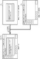
- FIG. 1 It is a figure which shows the structure of the equipment management system which concerns on Embodiment 1 of this invention. It is a figure which shows the structure of an equipment management apparatus.
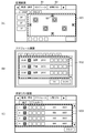
- A is a figure which shows the example of a monitoring screen.
- B is a figure which shows the example of a schedule screen.
- C is a figure which shows the example of a state list screen. It is a figure for demonstrating the relationship between image data and scroll image data. It is the figure which showed the structural example of the screen operation
- Embodiment 1 A facility management system 1 according to Embodiment 1 of the present invention will be described.
- the equipment management system 1 is a system that manages equipment installed in a facility.
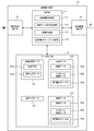
- the facility management system 1 includes a facility management device 10 and a display device 20 as shown in FIG.
- the equipment management apparatus 10 is connected to equipment equipment 30 1 to 30 n such as an air conditioner and lighting via a dedicated communication line 40, and monitors and controls each equipment equipment 30 1 to 30 n .
- equipment equipment 30 1 to 30 n such as an air conditioner and lighting
- the facility equipment 30 is denoted by a reference numeral and will be described below.
- the facility management apparatus 10 communicates with the display terminal 20 wirelessly, and transmits screen data for a screen (management screen) for managing the facility device 30 to the display terminal 20.
- the equipment management apparatus 10 is a computer having a CPU (Central Processing Unit), ROM (Read Only Memory), RAM (Random Access Memory), a readable / writable semiconductor memory such as a hard disk drive or a flash memory, and a communication interface. is there.
- the facility management apparatus 10 functionally includes a control unit 11, a data storage unit 12, a display terminal communication unit 13, and a facility device communication unit 14.
- the control unit 11 controls the overall operation of the facility management apparatus 10.
- the control unit 11 includes an equipment device management unit 111, a screen data update management unit 112, an image creation unit 113, and a screen operation table creation unit 114.
- the equipment device management unit 111 manages the equipment device 30. Specifically, the facility device management unit 111 monitors the operation state of the facility device 30 by sequentially receiving information indicating the operation state from the facility device 30. In addition, the facility device management unit 111 controls the operation of the facility device 30 in accordance with an instruction from the user or a predetermined condition. For example, the facility device management unit 111 performs control such as detecting an abnormality of the facility device 30 from the operation state of the facility device 30 and stopping the operation of the facility device 30 that has detected the abnormality.
- the screen data update management unit 112 updates the screen data for the management screen at a predetermined update timing (created when the facility management apparatus 10 is activated), and transmits the updated screen data to the display terminal 20.
- the image creation unit 113 creates an image (image data 122a, scroll image data 122b) to be displayed on the management screen.
- the screen operation table creation unit 114 creates, for each management screen, a screen operation table in which the content of the operation performed on the management screen is associated with the content of the operation by the operation.
- the data storage unit 12 stores various data necessary for the facility management apparatus 10 to manage the facility device 30. For example, facility data 121, screen data 122 1 to 122 m , and screen metadata 123 are stored in the data storage unit 12.
- the equipment data 121 is data related to equipment to be managed. For example, in the equipment data 121, connection information 121a and operation state data 121b are stored.
- the connection information 121a is fixed information necessary for specifying or accessing each facility device 30 such as ID information, address information, operation group number, and model identification information of each facility device 30.
- the operation state data 121b is the current operation state of the facility device 30 received from each facility device 30 (for example, in the case of an air conditioner, the operation / stop state, the operation mode such as cooling or heating, the set temperature, the room temperature, etc.) It is data which shows.
- the facility device management unit 111 receives the operation state data 121b from each facility device 30 periodically (for example, every minute), and updates the operation state data 121b stored in the facility device data 121 to the latest data.
- the screen data 122 1 to 122 m is data defining a management screen created for each management screen displayed on the display terminal 20.
- the management screen is, for example, a monitoring screen, a schedule screen, a status list screen, etc. as shown in FIGS.
- m management screens are assumed, and the data storage unit 12 stores m screen data 122 1 to 122 m .
- the screen data 122 and a reference numeral are attached and will be described below.
- the screen data 122 for each management screen is assigned a screen ID that can uniquely identify the management screen.
- Each screen data 122 includes image data 122a, scroll image data 122b, and a screen operation table 122c.
- the image data 122a is image data of an image displayed on the management screen.
- the image data 122a is, for example, data in GIF (Graphics Interchange Format) format, JPEG (Joint Photographic Experts Group) format, or BMP (Bitmap) format.
- GIF Graphics Interchange Format
- JPEG Joint Photographic Experts Group
- BMP Bitmap
- the scroll image data 122b is image data of an image that is scroll-displayed within a predetermined area (scroll area) of the management screen. For example, in the management screens shown in FIGS. 3A to 3C, areas SC1 to SC3 surrounded by dotted lines are scroll areas.
- the scroll image data 122b is, for example, GIF format, JPEG format, or BMP format data. When there are a plurality of scroll areas in the management screen, it is necessary to store a plurality of scroll image data 122b.
- FIG. 4A and 4B are diagrams showing the image data 122a and scroll image data 122b of the monitoring screen shown in FIG. A part of the scroll image data 122b shown in FIG. 4B is scrolled and displayed in the scroll area SC1 of the image data 122a shown in FIG. In this example, the scroll image data 122b is about four times as large as the scroll area SC1.
- the screen operation table 122c is created by the screen operation table creation unit 114.
- the screen operation table creation unit 114 is a table in which the contents of operations performed on the management screen are associated with the contents of operations by the operations.
- FIG. 5 is a diagram showing a part of the screen operation table 122c corresponding to the monitoring screen shown in FIG.
- a plurality of records in which an operation content including a screen ID, an operation area, and an operation category and an operation content including an operation category and a processing content are associated with each other are entered.
- the screen ID is identification information of the management screen, and since FIG. 5 is the screen operation table 122c corresponding to the monitoring screen, “S001” indicating the identification information of the monitoring screen is stored in the screen operation table 122c.
- the operation area indicates a portion where an operation such as touch or click is performed from the management screen.
- the operation area of the first entry in the screen operation table 122c shown in FIG. 5 corresponds to the area of the schedule button B1 on the monitoring screen shown in FIG.
- the operation area of the second entry corresponds to the area of the status list button B2 on the monitoring screen.
- the operation areas of the third and fourth entries correspond to the area of the up scroll button B3 of the monitoring screen.
- the operation classification indicates what kind of operation is performed on the operation area, and includes “touch”, “continuous press”, “drag”, “play with a finger”, and the like.
- the action classification indicates the type of action performed when the operation indicated by the operation content is performed, and includes “screen transition”, “scroll”, and the like.
- the processing contents indicate what kind of processing is specifically performed in the above operation.
- the screen metadata 123 is various data necessary for creating each management screen.
- the screen metadata 123 stores screen configuration information indicating the position of buttons in each management screen, a screen ID, a template image for creating each management screen, and the like.
- the equipment communication unit 14 includes a communication interface for connecting to the dedicated communication line 40, and transmits / receives various data to / from each equipment 30 connected to the dedicated communication line 40.
- the display terminal communication unit 13 includes a predetermined wireless communication interface, and transmits / receives data to / from the display terminal 20.
- the display terminal 20 functions as a user interface of the facility management system 1.
- the display terminal 20 communicates with the equipment management apparatus 10 by a predetermined wireless method, and displays a management screen for managing the equipment 30 based on the screen data received from the equipment management apparatus 10. Further, the display terminal 20 transmits instruction information input from the user to the facility management apparatus 10. Thereby, the equipment device management apparatus 10 controls the equipment device 30.
- the display terminal 20 includes a display unit 21, an input unit 22, a control unit 23, a data storage unit 24, and a communication unit 25.
- the display unit 21 is a liquid crystal display or the like, and displays a management screen based on the control of the control unit 23.
- the input unit 22 is an input device such as a touch panel or a mouse. When the user operates the input unit 22 and touches or clicks on the management screen displayed on the display unit 21, the input unit 22 performs an operation indicating the position coordinates in the operated management screen and the type of operation. Information is output to the control unit 23. When the input unit 22 is a touch panel, the input unit 22 is disposed on the display screen of the display unit 21.
- the control unit 23 controls the overall operation of the display terminal 201.
- the control unit 23 includes a screen data update management unit 231 and a screen display control unit 232.
- the screen data update management unit 231 updates the screen data 241 1 to 241 m stored in the data storage unit 24.
- the screen display control unit 232 controls the display of the management screen displayed on the display unit 21. For example, the screen display control unit 232 changes the management screen or scrolls the scroll image based on the operation information output from the input unit 22 and the screen operation table 241c.
- the data storage unit 24 stores screen data 241 1 to 241 m for management screens for each management screen.
- Each screen data 241 includes image data 241a, scroll image data 241b, and a screen operation table 241c. Note that the screen data 241 stored in the data storage unit 24 of the display terminal 20 is synchronized with the screen data 122 stored in the data storage unit of the facility management apparatus 10, and both are data having the same contents. is there.
- the communication unit 25 includes a predetermined wireless communication interface and transmits / receives data to / from the facility management apparatus 10.
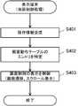
- the operation of the startup process executed when the facility management apparatus 10 is started will be described with reference to the flowchart of FIG.
- the equipment management device 10 does not know the operation state of the equipment 30, so the screen data 122 for the management screen is stored in the data storage unit 12. Shall not.
- the facility apparatus management unit 111 When the user activates the facility management apparatus 10 by pressing a start button of the facility management apparatus 10 or the like, first, the facility apparatus management unit 111 refers to the connection information 121a in the facility apparatus data 121 and each facility apparatus 30. , The operation state data 121b indicating the operation state of each facility device 30 is acquired and stored in the facility device data 121 (step S101). In addition, when the equipment device 30 is not activated (when the power is OFF), the equipment device management unit 111 may obtain the operation state data 121b after the equipment device 30 is activated.
- the screen data update management unit 112 creates screen data 122 for a management screen. Since the screen data 122 is not stored in the data storage unit 12 at this time, the screen data update management unit 112 creates screen data 122 for all management screens.
- the screen data update management unit 112 refers to the screen metadata 123 and identifies a management screen that needs to be created. Then, the screen data update management unit 112 selects one management screen for which screen data has not yet been created among the specified management screens (step S101).
- the screen data update management unit 112 instructs the image creation unit 113 to create image data for the selected management screen.
- the image creating unit 113 creates image data 122a in which the operation state data 121b acquired in step S101 is added to a predetermined position of the template image on the selected management screen (step S101).
- the screen data update management unit 112 instructs the image creation unit 113 to create scroll image data to be displayed in the scroll area.
- the image creating unit 113 creates scroll image data 122b in which the operation state data 121b acquired in step S101 is added to a predetermined position of the corresponding template image (step S101).
- the screen data update management unit 112 instructs the screen operation table creation unit 114 to select the screen operation table 122c of the selected management screen.
- the screen operation table creation unit 114 creates the screen operation table 122c by analyzing the source code stored in advance in the data storage unit 12 describing the display operation of the management screen. (Step S101).
- the screen operation table 122c may be created in advance and stored in a ROM or the like before the facility management apparatus 10 is shipped from the factory.
- the screen data update management unit stores the image data, scroll image data, and screen operation table 122c created in steps S101 to S101 in the data storage unit 12 as screen data 122 for the selected management screen. (Step S101).
- the screen data update management unit 112 determines whether there is a management screen for which the screen data 122 has not yet been created (step S101).
- step S101 If there is a management screen for which screen data has not been created (step S101; Yes), the screen data update management unit 112 selects the management screen and repeats the process of creating the screen data 122 (steps S101 to S101). Step S101).
- step S101 When there is no management screen for which screen data has not been created (step S101; No), the screen data update management unit 112 controls the display terminal communication unit 13 to display all the created screen data 122 on the display terminal 20. It transmits by radio (step S101). This is the end of the startup process of the facility management apparatus 10.
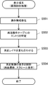
- the screen data update management unit 112 of the facility management apparatus 10 determines whether or not a predetermined update condition is met (step S201). For example, the screen data update management unit 112 may change the operating state data 121b from a value currently held because the facility device 30 is operated by a user operation or an abnormality occurs in the facility device 30. It may be determined that the update condition is met. Alternatively, the screen data update management unit 112 may determine that the update condition has been met when a predetermined time has elapsed or when the date has changed.
- the screen data update management unit 112 identifies a management screen whose display content needs to be updated (step S202). For example, when it is determined that the operation state data 121b has changed to meet the update condition, the screen data update management unit 112 may specify a management screen on which the changed operation state data 121b is displayed. Alternatively, if it is determined that the update condition is met because the date has changed, the screen data update management unit 112 may specify a management screen on which the date is displayed.
- the screen data update management unit 112 selects one management screen identified in step S202 (step S203).
- the screen data update management unit 112 newly creates image data and scroll image data for the selected management screen (step S204, step S205). This process is substantially the same as step S101 and step S101 of the startup process described above.
- the screen data update management unit 112 updates the screen data 122 stored in the data storage unit 12 (step S206). Specifically, the screen data update management unit 121 converts the image data 122a and the scroll image data 122b of the screen data 122 corresponding to the selected management screen stored in the data storage unit 122 into steps S204 and S205. The image data 122a and the scroll image data 122b created in the above are updated.
- the screen data update management unit 112 determines whether or not there is a management screen that has not been updated in step S206 among the management screens identified in step S202 as being necessary to be updated. (Step S207).
- step S207 If there is a management screen that has not been updated (step S207; Yes), the screen data update management unit 112 selects the management screen and repeats the process of updating the screen data 122 (step S203). To Step S206).
- the screen data update management unit 112 controls the display terminal communication unit 13 to store only the screen data 122 updated in step S206. It transmits to the display terminal 20 (step S208). This is the end of the screen update process.
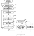
- the screen data update management unit 231 of the display terminal 20 stores the received screen data 241 in the data storage unit 24 ( Step S301).
- the screen data update management unit 231 updates the screen data 241 to the received screen data 241.
- the screen data update management unit 231 determines whether or not the screen data corresponding to the management screen being displayed on the display unit 21 has been updated in the process of step S301 (step S302). If it has not been updated (step S302; No), the screen update process ends.
- step S302 If it has been updated (step S302; Yes), the screen data update management unit 231 updates the management screen being displayed on the display unit 21 based on the updated screen data 241 (step S303). Thus, the screen data reception process ends.
- the user performs an operation such as touching or clicking the management screen displayed on the display unit 21 via the input unit 22.
- the input unit 22 transmits operation information indicating the position coordinates of the operated management screen and the type of operation (touch or click) to the screen display control unit 232.
- the screen display control unit 232 identifies the corresponding entry in the screen operation table 241c based on the position coordinates indicated by the operation information and the type of operation (step S402). . For example, when the screen operation table 241c corresponding to the management screen being displayed is configured as shown in FIG. 5 and operation information indicating that the position (300, 10) has been touched is received from the input unit 22.
- the screen display control unit 232 identifies the top entry. If the entry cannot be specified, for example, a portion not defined as the operation area of the screen operation table 241c is clicked. The screen control process ends without performing the subsequent processes.
- the screen display control unit 232 subsequently displays the management screen displayed on the display unit 21 for other management based on the operation content (operation category and processing content) of the identified entry. Control such as transition to the screen or scrolling of the image in the scroll area is performed (step S403). For example, when the head entry of the screen operation table 241c illustrated in FIG. 5 is specified, the screen display control unit 232 switches the display to the management screen having the screen ID “S002”. Thus, the screen control process ends.
- the equipment management apparatus 10 creates images (image data 122a and scroll image data 122b) for each management screen,
- the screen operation table 122c that defines the operation according to the operation on the management screen is transmitted to the display terminal 20 in advance. Therefore, in the display terminal 20, when an operation is performed on the management screen, the display operation can be performed only on the display terminal 20 without referring to the equipment management apparatus 10 by referring to the screen operation table 122 c. Screen switching processing and scroll display processing can be performed. Therefore, in the equipment management system 1, it becomes possible to improve the responsiveness of the management screen when operated by the user as compared with the conventional case.
- the screen data for the management screen is updated in the facility management apparatus 10
- only the updated screen data is transmitted to the display terminal 20, and the display terminal The screen data stored in 20 is updated in the same manner. Therefore, the latest information can be displayed on the management screen displayed on the display terminal 20 while suppressing the communication amount between the display terminal 20 and the facility management apparatus 10.
- the facility management system 1 does not require the display terminal 20 to perform screen creation processing by itself, and simply displays the screen data and scroll image data received from the facility management apparatus 10 as they are. good. Therefore, on the display terminal 20 side, it is not necessary to prepare a high-performance GUI (Graphical User Interface) execution environment, and the processing load is light, so that a relatively inexpensive CPU can be used. Therefore, the display terminal 20 can be manufactured at a low cost.
- GUI Graphic User Interface
- the facility management system 1 does not require a GUI execution environment such as a browser in the display terminal 20, and therefore, when a management screen is displayed on a personal computer screen, the OS (Operation) There is no problem that the display operation is changed depending on the version of the GUI execution environment such as (System), the browser, and the Java (registered trademark) applet.
- the facility management system 1 includes a management screen displayed on the display unit of the facility management device 10 and a display even when the facility management device 10 includes the display unit.
- the management screen displayed on the terminal 20 is the same. Accordingly, there is no need to create a management screen dedicated to the browser, as in the case of performing monitoring work using the browser screen of the personal computer, and the labor of developing the management screen twice can be saved.
- Embodiment 2 the equipment management system concerning Embodiment 2 of the present invention is explained.
- the equipment management system according to Embodiment 2 of the present invention the equipment according to Embodiment 1 except that the image data for displaying the management screen and the scroll image data are composed of images of a plurality of layers.
- the configuration is substantially the same as that of the management system 1.
- the same referential mark is attached
- FIG. 11A shows the configuration of the image data 122a and 241a stored in the facility management apparatus 10 and the display terminal 20.
- the image data 122a and 241a includes a plurality of image layers DL 1 to DL n .
- the images represented by the image data 122a and 241a are images obtained by superimposing the image layers DL 1 to DL n .
- the relationship between the image data 122a and 241a and the image layer DL will be specifically described with reference to FIG.
- the image layer DL 1 for the background, the layer combining the image layer DL 2 for message display (overlay) were image data 122a, 241a is created.
- FIG. 11B shows the configuration of the scroll image data 122b and 241b stored in the facility management apparatus 10 and the display terminal 20.
- the scroll image data 122b and 241b includes a plurality of image layers SL 1 to SL n .
- the image indicated by the scroll image data 122b and 241b is an image obtained by superimposing the scroll image layers SL 1 to SL n .
- the relationship between the scroll image data 122b and 241b and the scroll image layer SL will be specifically described with reference to FIG.
- the scroll image layer SL 1 for the background, equipment icon image layer DL 2 layer synthesis (superposition) of the display was the scroll image data 122b, 241b is created.
- FIG. 14 it is possible to define an operation for the operation content in the screen operation tables 122c and 241c for each image layer DL or scroll image layer SL.
- the management screen area ((200, 0)-(349, 39)) is touched from the head entry of the screen operation tables 122c and 241c shown in FIG. 14, the image layer DL 1 has the image layer as the background. It can be seen that the screen transitions to an image in which DL 2 is layered.
- the screen display control unit 232 of the display terminal 20 receives the operation information from the input unit 22 by an operation from the user (step S501), based on the position coordinates indicated by the operation information and the type of operation, the corresponding screen operation table is displayed.
- the entry of 241c is specified (step S502). For example, when the screen operation table 241c corresponding to the management screen being displayed is configured as shown in FIG. 14 and operation information indicating that the position (300, 10) has been touched is received from the input unit 22.
- the screen display control unit 232 identifies the top entry.
- the screen display control unit 232 creates image data 241a (or scroll image data 241b) obtained by layer combining the layer image DL (or scroll layer image SL) based on the processing content of the specified entry (step S503). ). For example, when the top entry of the screen operation table 241c shown in FIG. 14 is specified, the screen display control unit 232 creates screen data in which the image layer 2 is combined with the image layer 1 as a background.
- the screen display control unit 232 displays the screen data created by layer synthesis based on the identified action category (step S504). For example, the screen display control unit 232 switches the display so that the management screen based on the image data 241 a obtained by layer combining the image layer DL 1 and the image layer DL 1 is displayed on the display unit 21.
- image data for one management screen is created and displayed by superimposing a plurality of image layers. Therefore, for example, when the message window is displayed and is not displayed again, it is possible to switch the screen at high speed without requiring transmission / reception of a screen image between the display terminal 20 and the facility management apparatus 10.
- one scroll image data is created and displayed by superimposing a plurality of scroll image layers. Therefore, for example, a scroll operation such as scrolling only the equipment icon without scrolling the background can be performed without requiring transmission / reception of a screen image between the display terminal 20 and the equipment management apparatus 10, so that high-speed scrolling is possible. Display is possible.
- a plurality of image layers for displaying subtitles are stored for each language. Then, by performing display / non-display designation of the image layer in the screen operation table 241c, it is possible to easily switch the caption display corresponding to the language of each country.
- the equipment management device 10 can update the equipment device icon layer. It is only necessary to update and transmit to the display terminal 20. If it does in this way, since it becomes the same color (transparent color) except an equipment icon part, a compression rate becomes high and it becomes possible to suppress the load concerning communication.
- Embodiment 3 the equipment management system 1A which concerns on Embodiment 3 of this invention is demonstrated.
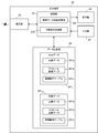
- the facility management system 1A according to Embodiment 3 of the present invention is different from the facility management system 1 according to Embodiment 1 in that it includes a plurality of display terminals 20 1 to 20 n as shown in FIG.
- the same referential mark is attached
- a common multicast address is set for the facility management apparatus 10 and the plurality of display devices 20 1 to 20 n . Therefore, the facility management apparatus 10 can simultaneously transmit (multicast transmission) the updated image data 122a to each of the display apparatuses 20 1 to 20 n at the same timing through wireless communication.
- step S601 to S607 for updating the contents of the screen data 122 for management screen that needs to be updated when a predetermined update condition is met is the step S201 of the screen update process described in the flowchart of FIG. This process is substantially the same as the process of S207.
- step S607 If it is determined in step S607 that there is no management screen for which the screen data 122a has not been updated (step S607; No), the screen data update management unit 112 determines whether or not the multicast address set in itself is valid. Is discriminated (step S608).
- step S608 If it is not valid (step S608; No), since multicast transmission cannot be performed, the screen data update management unit 112 has one specific display terminal 20 (for example, the display terminal 20 owned by the administrator's leader).
- the screen data 122 updated in step S606 is transmitted (step S609).
- step S608 If it is valid (step S608; Yes), the screen data update management unit 112 simultaneously transmits the screen data 122 updated in step S606 to the plurality of display terminals 20 1 to 20 n for which the multicast address is set. Send (multicast). Thus, the screen update process ends (step S610).
- the multicast address is used to simultaneously transmit the screen data 122a to the plurality of display terminals 20 1 to 20 n .
- the multicast address is not necessarily used.
- a method using a broadcast address that can be received by a plurality of display terminals in one transmission may be used.
- screen data is simultaneously transmitted to a plurality of display terminals 20 without increasing the transmission processing load of the facility management device 10. Can be sent to. Therefore, it is possible to easily monitor the equipment 30 from a plurality of locations without degrading the performance of the equipment management apparatus 10.
- the display terminal 20 can be manufactured with a low-cost CPU because the processing load is low.
- the display terminal 20 is less expensive than using a general-purpose personal computer or tablet. This makes it possible to construct an equipment management system.
- the display terminal 20 may be an existing smartphone, a PDA (Personal Digital Assistant), or the like.
- the personal computer or the like can function as the facility management apparatus according to the present invention. Is also possible.
- Such a program distribution method is arbitrary, for example, a computer-readable recording medium such as a CD-ROM (Compact Disk Read-Only Memory), a DVD (Digital Versatile Disk), an MO (Magneto Optical Disk), or a memory card. It may be stored and distributed in a network, or distributed via a communication network such as the Internet.
- a computer-readable recording medium such as a CD-ROM (Compact Disk Read-Only Memory), a DVD (Digital Versatile Disk), an MO (Magneto Optical Disk), or a memory card. It may be stored and distributed in a network, or distributed via a communication network such as the Internet.
- the present invention can be suitably employed in an equipment management apparatus that manages equipment installed in a building or the like.
Abstract
Description
これらの技術では、サーバは、クライアントからマウス入力等による操作情報を受信すると、受信した操作情報に応じてクライアント用の画面の画面データを新たに作成してクライアントに送信する。そして、クライアントは、サーバから受信した画面データに基づいて、別の画面に表示を切り替えたり画像をスクロールして表示さる。従って、これらの技術では、ユーザがクライアントを操作をする度に、サーバとの通信処理が発生するため、クライアントに表示されている画面を切り替えたり、画像をスクロールして表示させる処理に時間がかかってしまうという課題があった。 VNC (Virtual Network Computing) and a remote desktop system are known as techniques for displaying a screen held by a server as it is on a client.
In these techniques, when the server receives operation information by mouse input or the like from the client, the server newly creates screen data for the client screen according to the received operation information and transmits it to the client. Then, based on the screen data received from the server, the client switches the display to another screen or scrolls and displays the image. Therefore, in these technologies, every time the user operates the client, a communication process with the server occurs. Therefore, it takes time to switch the screen displayed on the client or to display the image by scrolling. There was a problem that it would end up.
具体的には、特許文献1では、サーバは、クライアント端末に送信した画像データを、この画像データの固有値(例えばハッシュ値)とともにテーブルに格納する。そして、クライアントに画像データを送信する際、サーバは、この画像データの固有値が既にテーブルに格納されているか否かを判別し、既に格納されている場合には、この画像データを送信せず、固有値のみを送信する。
Specifically, in
施設内に設置された設備機器を管理する設備管理装置であって、
前記設備機器の管理用画面毎に、前記管理用画面を表示させるための画面データと、前記管理用画面上からなされた操作の内容と該操作による表示端末の動作内容とを対応付けた画面動作テーブルと、を記憶する画面記憶部と、
所定のタイミングで前記管理用画面に対応した、画面データと画面動作テーブルとを前記表示端末に送信する画面送信部と、
を備える。 In order to achieve the above object, the facility management apparatus of the present invention provides:
An equipment management device for managing equipment installed in a facility,
Screen operation for displaying the management screen for each management device management screen, the screen operation in which the content of the operation performed on the management screen and the operation content of the display terminal by the operation are associated with each other A screen storage unit for storing a table;
A screen transmission unit that transmits screen data and a screen operation table corresponding to the management screen at a predetermined timing to the display terminal;
Is provided.
本発明の実施形態1に係る設備管理システム1について説明する。設備管理システム1は、施設内に設置された設備機器を管理するシステムである。設備管理システム1は、図1に示すように、設備管理装置10と表示装置20とを備える。 <<
A
運転状態データ121bは、各設備機器30から受信した、設備機器30の現在の運転状態(例えば空調機の場合は運転・停止状態や、冷房や暖房などの運転モード、設定温度、室内温度など)を示すデータである。設備機器管理部111は、定期的(例えば1分毎)に各設備機器30から運転状態データ121bを受信し、設備機器データ121に格納されている運転状態データ121bを最新のデータに更新する。 The
The
操作領域は、管理用画面内からタッチやクリック等の操作がなされた部分を示す。図5に示す画面動作テーブル122cの先頭のエントリの操作領域は、図3(A)に示す監視画面のスケジュールボタンB1の領域に対応する。同様に、2番目のエントリの操作領域は、監視画面の状態リストボタンB2の領域に対応する。また、3番目と4番目のエントリの操作領域は、監視画面の上スクロールボタンB3の領域に対応する。
操作区分は、操作領域に対してどのような種類の操作がなされたかを示し、「タッチ」や「連続押」や「ドラッグ」や「指で弾く」等が有るものとする。 The screen ID is identification information of the management screen, and since FIG. 5 is the screen operation table 122c corresponding to the monitoring screen, “S001” indicating the identification information of the monitoring screen is stored in the screen operation table 122c.
The operation area indicates a portion where an operation such as touch or click is performed from the management screen. The operation area of the first entry in the screen operation table 122c shown in FIG. 5 corresponds to the area of the schedule button B1 on the monitoring screen shown in FIG. Similarly, the operation area of the second entry corresponds to the area of the status list button B2 on the monitoring screen. The operation areas of the third and fourth entries correspond to the area of the up scroll button B3 of the monitoring screen.
The operation classification indicates what kind of operation is performed on the operation area, and includes “touch”, “continuous press”, “drag”, “play with a finger”, and the like.
処理内容は、上記の動作において、具体的にどのような処理がなされるかを示す。 The action classification indicates the type of action performed when the operation indicated by the operation content is performed, and includes “screen transition”, “scroll”, and the like.
The processing contents indicate what kind of processing is specifically performed in the above operation.
また、3番目のエントリからは、監視画面の上スクロールボタンB3をタッチした場合に、スクロール画像データ122bが上方へ100ドットスクロールすることがわかる。 For example, it can be seen from the top entry of the screen operation table 122c shown in FIG. 5 that when the schedule button B1 on the monitoring screen is touched, the display transitions (switches) to the schedule screen having the screen ID “S002”.
From the third entry, it can be seen that when the up scroll button B3 of the monitoring screen is touched, the
続いて、本発明の実施形態2に係る設備管理システムについて説明する。本発明の実施形態2に係る設備管理システムでは、管理用画面を表示するための画像データとスクロール画像データとが、複数のレイヤ毎の画像から構成される点以外は、実施形態1に係る設備管理システム1と実質的に同じ構成である。なお、実施形態1に係る設備管理装置10及び表示端末20と実質的に同じ構成要素については、同じ参照符号を付し、説明を適宜省略する。 <<
Then, the equipment management
続いて、本発明の実施形態3に係る設備管理システム1Aについて説明する。本発明の実施形態3に係る設備管理システム1Aは、図16に示すように、複数の表示端末201~20nを備える点が、実施形態1に係る設備管理システム1と異なる。なお、実施形態1に係る設備管理装置10及び表示端末20と実質的に同じ構成要素については、同じ参照符号を付し、説明を適宜省略する。 <<
Then, the
11 制御部
111 設備機器管理部
112 画面データ更新管理部
113 画像作成部
114 画面動作テーブル作成部
12 データ記憶部
121 設備機器データ
121a 接続情報
121b 運転状態データ
122 画面データ
122a 画像データ
122b スクロール画像データ
122c 画面動作テーブル
123 画面メタデータ
13 表示端末通信部
14 設備機器通信部
20 表示端末
30 設備機器
40 専用線 DESCRIPTION OF
Claims (10)
- 施設内に設置された設備機器を管理する設備管理装置であって、
前記設備機器の管理用画面毎に、前記管理用画面を表示させるための画面データと、前記管理用画面上からなされた操作の内容と該操作による表示端末の動作内容とを対応付けた画面動作テーブルと、を記憶する画面記憶部と、
所定のタイミングで前記管理用画面に対応した、画面データと画面動作テーブルとを前記表示端末に送信する画面送信部と、
を備える設備管理装置。 An equipment management device for managing equipment installed in a facility,
Screen operation for displaying the management screen for each management device management screen, the screen operation in which the content of the operation performed on the management screen and the operation content of the display terminal by the operation are associated with each other A screen storage unit for storing a table;
A screen transmission unit that transmits screen data and a screen operation table corresponding to the management screen at a predetermined timing to the display terminal;
An equipment management apparatus comprising: - 所定の更新条件に合致した際に、所定の更新内容に基づいて、前記画面データを更新する画面更新部と、
前記画面更新部によって更新された画面データのみを前記表示端末に送信する更新画像送信部と、
を備える請求項1に記載の設備管理装置。 A screen update unit that updates the screen data based on predetermined update content when a predetermined update condition is met;
An updated image transmission unit for transmitting only the screen data updated by the screen update unit to the display terminal;
The facility management apparatus according to claim 1, comprising: - 前記画面動作テーブルは、前記管理用画面の表示中になされる操作の内容と、該操作によって表示の切り替わる先の管理用画面の識別情報とを対応付けた情報である、
請求項1又は2に記載の設備管理装置。 The screen operation table is information in which the content of an operation performed while the management screen is displayed is associated with the identification information of the management screen to which the display is switched by the operation.
The facility management apparatus according to claim 1 or 2. - 前記管理用画面は、複数のレイヤ毎の画像を合成した画面である、
請求項1乃至3の何れか1項に記載の設備管理装置。 The management screen is a screen obtained by combining images of a plurality of layers.
The equipment management apparatus according to any one of claims 1 to 3. - 前記管理用画面に対応する画面データは、該管理用画面のスクロール領域内でスクロール表示させるスクロール画像のデータを含み、
前記画面動作テーブルは、前記管理用画面の表示中になされる操作の内容と、該操作によってスクロール領域内でスクロール表示されるスクロール画像の識別情報とを対応付けた情報である、
請求項1乃至4の何れか1項に記載の設備管理装置。 The screen data corresponding to the management screen includes scroll image data to be scroll-displayed in a scroll area of the management screen,
The screen operation table is information in which the content of an operation performed while the management screen is displayed is associated with identification information of a scroll image scroll-displayed in the scroll area by the operation.
The equipment management apparatus according to any one of claims 1 to 4. - 前記スクロール画像は、複数のレイヤ毎の画像を合成した画像である、
請求項5に記載の設備管理装置。 The scroll image is an image obtained by combining images of a plurality of layers.
The facility management apparatus according to claim 5. - 前記画面送信部は、前記管理用画面に対応した、画面データと画面動作テーブルとを複数の表示端末に一斉に送信する、
請求項1乃至6の何れか1項に記載の設備管理装置。 The screen transmission unit transmits screen data and a screen operation table corresponding to the management screen to a plurality of display terminals all at once.
The equipment management apparatus according to any one of claims 1 to 6. - 施設内に設置された設備機器を管理する設備管理方法であって、
前記設備機器の管理用画面毎に、前記管理用画面を表示させるための画面データと、前記管理用画面上からなされた操作の内容と該操作による表示端末の動作内容とを対応付けた画面動作テーブルとを記憶し、
所定のタイミングで前記管理用画面に対応した、画面データと画面動作テーブルとを前記表示端末に送信する、
設備管理方法。 An equipment management method for managing equipment installed in a facility,
Screen operation for displaying the management screen for each management device management screen, the screen operation in which the content of the operation performed on the management screen and the operation content of the display terminal by the operation are associated with each other Remember table and
Transmitting screen data and a screen operation table corresponding to the management screen at a predetermined timing to the display terminal;
Equipment management method. - 施設内に設置された設備機器を管理するコンピュータを、
前記設備機器の管理用画面毎に、前記管理用画面を表示させるための画面データと、前記管理用画面上からなされた操作の内容と該操作による表示端末の動作内容とを対応付けた画面動作テーブルと、を記憶する画面記憶部、
所定のタイミングで前記管理用画面に対応した、画面データと画面動作テーブルとを前記表示端末に送信する画面送信部、
として機能させるプログラム。 A computer that manages the equipment installed in the facility
Screen operation for displaying the management screen for each management device management screen, the screen operation in which the content of the operation performed on the management screen and the operation content of the display terminal by the operation are associated with each other A screen storage unit for storing the table,
A screen transmission unit for transmitting screen data and a screen operation table corresponding to the management screen at a predetermined timing to the display terminal;
Program to function as. - 施設内に設置された設備機器を管理する設備管理装置と、表示端末と、を備えた設備管理システムであって、
前記設備管理装置は、
前記設備機器の管理用画面毎に、前記管理用画面を表示させるための画面データと、前記管理用画面上からなされた操作の内容と該操作による表示端末の動作内容とを対応付けた画面動作テーブルと、を記憶する画面記憶部と、
所定のタイミングで前記管理用画面に対応した、画面データと画面動作テーブルとを前記表示端末に送信する画面送信部と、を備え、
前記表示端末は、
前記設備管理装置とデータ通信する通信部と、
前記設備管理装置から送信された前記画面データと前記画面動作テーブルとを前記管理用画面毎に記憶するデータ記憶部と、
前記データ記憶部に記憶されている前記画面データに基づいて、前記管理用画面を表示する管理用画面表示部と、
前記データ記憶部に記憶されている前記画面動作テーブルに基づいて、前記管理用画面の表示中になされた操作に対応した動作を実行する表示制御部と、
を備える設備管理システム。 An equipment management system comprising an equipment management device for managing equipment installed in a facility, and a display terminal,
The facility management apparatus is
Screen operation for displaying the management screen for each management device management screen, the screen operation in which the content of the operation performed on the management screen and the operation content of the display terminal by the operation are associated with each other A screen storage unit for storing a table;
A screen transmitting unit that transmits screen data and a screen operation table corresponding to the management screen at a predetermined timing to the display terminal;
The display terminal is
A communication unit for data communication with the facility management device;
A data storage unit that stores the screen data and the screen operation table transmitted from the facility management device for each management screen;
A management screen display unit for displaying the management screen based on the screen data stored in the data storage unit;
A display control unit that performs an operation corresponding to an operation performed during display of the management screen based on the screen operation table stored in the data storage unit;
Equipment management system comprising.
Priority Applications (4)
| Application Number | Priority Date | Filing Date | Title |
|---|---|---|---|
| CN201280067926.1A CN104081367A (en) | 2012-01-24 | 2012-01-24 | Equipment management device, equipment management method, program and equipment management system |
| PCT/JP2012/051463 WO2013111272A1 (en) | 2012-01-24 | 2012-01-24 | Equipment management device, equipment management method, program and equipment management system |
| EP12866459.6A EP2808799B1 (en) | 2012-01-24 | 2012-01-24 | Equipment management device, equipment management method, program and equipment management system |
| US14/366,081 US20140364968A1 (en) | 2012-01-24 | 2012-01-24 | Equipment management device, equipment management method, program and equipment management system |
Applications Claiming Priority (1)
| Application Number | Priority Date | Filing Date | Title |
|---|---|---|---|
| PCT/JP2012/051463 WO2013111272A1 (en) | 2012-01-24 | 2012-01-24 | Equipment management device, equipment management method, program and equipment management system |
Publications (1)
| Publication Number | Publication Date |
|---|---|
| WO2013111272A1 true WO2013111272A1 (en) | 2013-08-01 |
Family
ID=48873044
Family Applications (1)
| Application Number | Title | Priority Date | Filing Date |
|---|---|---|---|
| PCT/JP2012/051463 WO2013111272A1 (en) | 2012-01-24 | 2012-01-24 | Equipment management device, equipment management method, program and equipment management system |
Country Status (4)
| Country | Link |
|---|---|
| US (1) | US20140364968A1 (en) |
| EP (1) | EP2808799B1 (en) |
| CN (1) | CN104081367A (en) |
| WO (1) | WO2013111272A1 (en) |
Families Citing this family (7)
| Publication number | Priority date | Publication date | Assignee | Title |
|---|---|---|---|---|
| KR101968850B1 (en) * | 2015-04-21 | 2019-04-12 | 미쓰비시덴키 가부시키가이샤 | Information processing apparatus, information processing system, and recording medium |
| KR101886609B1 (en) * | 2015-10-30 | 2018-09-06 | 미쓰비시덴키 가부시키가이샤 | Programmable Indicators and Control Systems |
| JP6758863B2 (en) * | 2016-03-03 | 2020-09-23 | 株式会社ユニバーサルエンターテインメント | Information providing system and information providing device |
| CN109074324B (en) * | 2016-04-20 | 2021-08-17 | 三菱电机株式会社 | Programmable display, terminal device and control system |
| US20190063779A1 (en) * | 2016-05-16 | 2019-02-28 | Mitsubishi Electric Corporation | Air conditioning management device and program |
| JP7009736B2 (en) * | 2016-11-30 | 2022-01-26 | 株式会社リコー | Information processing equipment, control methods, programs, devices and information processing systems |
| JP7316254B2 (en) * | 2020-08-20 | 2023-07-27 | 株式会社日立ビルシステム | Operating state display device for building equipment and method for displaying operating state of building equipment |
Citations (4)
| Publication number | Priority date | Publication date | Assignee | Title |
|---|---|---|---|---|
| JPH11102289A (en) * | 1997-09-26 | 1999-04-13 | Hitachi Software Eng Co Ltd | Screen generating method for operation process |
| JP2001125628A (en) * | 1999-10-27 | 2001-05-11 | Nippon Sanso Corp | System monitor device and its recording medium |
| JP2007226635A (en) | 2006-02-24 | 2007-09-06 | Victor Co Of Japan Ltd | Server device and client device of remote desktop system |
| JP2012003310A (en) * | 2010-06-14 | 2012-01-05 | Toshiba Corp | Plant monitoring device and plant monitoring system |
Family Cites Families (4)
| Publication number | Priority date | Publication date | Assignee | Title |
|---|---|---|---|---|
| US5959628A (en) * | 1994-06-28 | 1999-09-28 | Libera, Inc. | Method for providing maximum screen real estate in computer controlled display systems |
| US6201996B1 (en) * | 1998-05-29 | 2001-03-13 | Control Technology Corporationa | Object-oriented programmable industrial controller with distributed interface architecture |
| JP2004510275A (en) * | 2000-09-28 | 2004-04-02 | ビジロス, インコーポレイテッド | System and method for dynamic interaction with a remote device |
| EP2031541A1 (en) * | 2007-09-03 | 2009-03-04 | LG Electronics Inc. | Facility management system and control method of facility management system |
-
2012
- 2012-01-24 EP EP12866459.6A patent/EP2808799B1/en active Active
- 2012-01-24 US US14/366,081 patent/US20140364968A1/en not_active Abandoned
- 2012-01-24 WO PCT/JP2012/051463 patent/WO2013111272A1/en active Application Filing
- 2012-01-24 CN CN201280067926.1A patent/CN104081367A/en active Pending
Patent Citations (4)
| Publication number | Priority date | Publication date | Assignee | Title |
|---|---|---|---|---|
| JPH11102289A (en) * | 1997-09-26 | 1999-04-13 | Hitachi Software Eng Co Ltd | Screen generating method for operation process |
| JP2001125628A (en) * | 1999-10-27 | 2001-05-11 | Nippon Sanso Corp | System monitor device and its recording medium |
| JP2007226635A (en) | 2006-02-24 | 2007-09-06 | Victor Co Of Japan Ltd | Server device and client device of remote desktop system |
| JP2012003310A (en) * | 2010-06-14 | 2012-01-05 | Toshiba Corp | Plant monitoring device and plant monitoring system |
Also Published As
| Publication number | Publication date |
|---|---|
| CN104081367A (en) | 2014-10-01 |
| EP2808799A4 (en) | 2016-04-27 |
| EP2808799A1 (en) | 2014-12-03 |
| EP2808799B1 (en) | 2018-05-23 |
| US20140364968A1 (en) | 2014-12-11 |
Similar Documents
| Publication | Publication Date | Title |
|---|---|---|
| WO2013111272A1 (en) | Equipment management device, equipment management method, program and equipment management system | |
| CN103154856B (en) | For the environmental correclation dynamic range control of gesture identification | |
| CN109478152B (en) | Cloud content state framework | |
| JP7087270B2 (en) | Information processing equipment and information processing programs | |
| TWI534694B (en) | Computer implemented method and computing device for managing an immersive environment | |
| EP3243133A1 (en) | Customizable bladed applications | |
| AU2013263738A1 (en) | Method for displaying applications and electronic device thereof | |
| JP6086955B2 (en) | Server apparatus, annotation method, and computer program | |
| JP2009211241A (en) | Display screen setting program, information processing apparatus and display screen setting method | |
| US20160092152A1 (en) | Extended screen experience | |
| JP2009223061A (en) | Display control system, display control method, and display control program | |
| JP2006330912A (en) | Information processor and program | |
| US20090235253A1 (en) | Smart task list/life event annotator | |
| US20120030595A1 (en) | Information storage medium, terminal apparatus, and image generation method | |
| JP2020067977A (en) | Information processing apparatus and program | |
| WO2016164702A1 (en) | Opening new application window in response to remote resource sharing | |
| JP6602190B2 (en) | Software development program and software development method | |
| EP2743826A1 (en) | Service providing device, and method of providing a user interface | |
| JP2010108331A (en) | Information processing apparatus, application starting method and program | |
| US9548894B2 (en) | Proximity based cross-screen experience App framework for use between an industrial automation console server and smart mobile devices | |
| JP6570436B2 (en) | Software development program and software development method | |
| JPWO2013111272A1 (en) | Equipment management device, equipment management method, program, and equipment management system | |
| JP2019029814A (en) | Communication system, communication method, and electronic apparatus | |
| TWI604382B (en) | Methods for sharing applications and systems using the same | |
| JP5300902B2 (en) | Screen control program and information processing apparatus |
Legal Events
| Date | Code | Title | Description |
|---|---|---|---|
| 121 | Ep: the epo has been informed by wipo that ep was designated in this application |
Ref document number: 12866459 Country of ref document: EP Kind code of ref document: A1 |
|
| ENP | Entry into the national phase |
Ref document number: 2013555035 Country of ref document: JP Kind code of ref document: A |
|
| WWE | Wipo information: entry into national phase |
Ref document number: 14366081 Country of ref document: US |
|
| NENP | Non-entry into the national phase |
Ref country code: DE |
|
| WWE | Wipo information: entry into national phase |
Ref document number: 2012866459 Country of ref document: EP |