WO2013108296A1 - Subject selection device and subject selection method - Google Patents
Subject selection device and subject selection method Download PDFInfo
- Publication number
- WO2013108296A1 WO2013108296A1 PCT/JP2012/000356 JP2012000356W WO2013108296A1 WO 2013108296 A1 WO2013108296 A1 WO 2013108296A1 JP 2012000356 W JP2012000356 W JP 2012000356W WO 2013108296 A1 WO2013108296 A1 WO 2013108296A1
- Authority
- WO
- WIPO (PCT)
- Prior art keywords
- objects
- suction
- opening
- passage
- downstream
- Prior art date
Links
Images


Classifications
-
- B—PERFORMING OPERATIONS; TRANSPORTING
- B01—PHYSICAL OR CHEMICAL PROCESSES OR APPARATUS IN GENERAL
- B01L—CHEMICAL OR PHYSICAL LABORATORY APPARATUS FOR GENERAL USE
- B01L3/00—Containers or dishes for laboratory use, e.g. laboratory glassware; Droppers
- B01L3/02—Burettes; Pipettes
- B01L3/0275—Interchangeable or disposable dispensing tips
-
- B—PERFORMING OPERATIONS; TRANSPORTING
- B01—PHYSICAL OR CHEMICAL PROCESSES OR APPARATUS IN GENERAL
- B01L—CHEMICAL OR PHYSICAL LABORATORY APPARATUS FOR GENERAL USE
- B01L2200/00—Solutions for specific problems relating to chemical or physical laboratory apparatus
- B01L2200/06—Fluid handling related problems
- B01L2200/0605—Metering of fluids
-
- B—PERFORMING OPERATIONS; TRANSPORTING
- B01—PHYSICAL OR CHEMICAL PROCESSES OR APPARATUS IN GENERAL
- B01L—CHEMICAL OR PHYSICAL LABORATORY APPARATUS FOR GENERAL USE
- B01L2200/00—Solutions for specific problems relating to chemical or physical laboratory apparatus
- B01L2200/06—Fluid handling related problems
- B01L2200/0647—Handling flowable solids, e.g. microscopic beads, cells, particles
- B01L2200/0668—Trapping microscopic beads
-
- B—PERFORMING OPERATIONS; TRANSPORTING
- B01—PHYSICAL OR CHEMICAL PROCESSES OR APPARATUS IN GENERAL
- B01L—CHEMICAL OR PHYSICAL LABORATORY APPARATUS FOR GENERAL USE
- B01L2300/00—Additional constructional details
- B01L2300/06—Auxiliary integrated devices, integrated components
- B01L2300/0681—Filter
-
- B—PERFORMING OPERATIONS; TRANSPORTING
- B01—PHYSICAL OR CHEMICAL PROCESSES OR APPARATUS IN GENERAL
- B01L—CHEMICAL OR PHYSICAL LABORATORY APPARATUS FOR GENERAL USE
- B01L2300/00—Additional constructional details
- B01L2300/08—Geometry, shape and general structure
- B01L2300/0848—Specific forms of parts of containers
- B01L2300/0858—Side walls
-
- B—PERFORMING OPERATIONS; TRANSPORTING
- B01—PHYSICAL OR CHEMICAL PROCESSES OR APPARATUS IN GENERAL
- B01L—CHEMICAL OR PHYSICAL LABORATORY APPARATUS FOR GENERAL USE
- B01L2400/00—Moving or stopping fluids
- B01L2400/06—Valves, specific forms thereof
- B01L2400/0605—Valves, specific forms thereof check valves
- B01L2400/0616—Ball valves
-
- B—PERFORMING OPERATIONS; TRANSPORTING
- B01—PHYSICAL OR CHEMICAL PROCESSES OR APPARATUS IN GENERAL
- B01L—CHEMICAL OR PHYSICAL LABORATORY APPARATUS FOR GENERAL USE
- B01L2400/00—Moving or stopping fluids
- B01L2400/06—Valves, specific forms thereof
- B01L2400/0633—Valves, specific forms thereof with moving parts
-
- G—PHYSICS
- G01—MEASURING; TESTING
- G01N—INVESTIGATING OR ANALYSING MATERIALS BY DETERMINING THEIR CHEMICAL OR PHYSICAL PROPERTIES
- G01N1/00—Sampling; Preparing specimens for investigation
- G01N1/28—Preparing specimens for investigation including physical details of (bio-)chemical methods covered elsewhere, e.g. G01N33/50, C12Q
- G01N1/40—Concentrating samples
- G01N1/4077—Concentrating samples by other techniques involving separation of suspended solids
- G01N2001/4088—Concentrating samples by other techniques involving separation of suspended solids filtration
Definitions
- the present invention relates to a suction tip. More specifically, when a collection of objects including particles of various sizes is sucked, only particles having a predetermined particle diameter or more are discharged, and particles having a particle diameter smaller than the predetermined particle diameter are stored inside.
- the present invention relates to a suction tip that can be used.
- suction pipettes for sucking and weighing a relatively small amount of liquid or the like are used.
- push button type suction pipettes that are used with a suction tip attached to the tip are frequently used.
- the suction pipette is originally for sucking a fixed volume of liquid, but is used for the purpose of moving an object from one place to another as a preliminary use method.
- the object includes not only the liquid but also powder, particles, cells, etc. contained in the liquid (hereinafter, these may be collectively referred to as a collection of objects). And these objects, such as powder, have various shapes and sizes (hereinafter, these may be collectively referred to as shapes).
- these objects such as powder
- shapes have various shapes and sizes (hereinafter, these may be collectively referred to as shapes).
- the small-size contaminants are previously removed from the target object.
- many contaminants such as organelles and disrupted cell membranes are contained. Sorted and removed in the initial stage.
- Patent Document 1 discloses a suction pipette in which a cup-shaped accommodation portion having an opening with a predetermined opening area is provided around a nozzle for sucking an object. The suction pipette sucks and selects an object having a diameter smaller than the opening area.
- Patent Document 2 discloses a filter unit that can be used in a suction pipette and can be loaded with a membrane filter. The filter unit of Patent Document 2 is used by being attached to a pipette tip of a suction pipette, and filters cells and the like from an object by a thin film filter loaded inside.
- Patent Document 1 has a problem that an object having a diameter larger than the opening area of the housing portion can be removed, but an object having a small diameter cannot be removed.
- the unit of Patent Document 2 has a problem that it is necessary to remove the filter when discharging cells or the like having a desired shape, which is troublesome and causes contamination.
- the present invention has been made in view of such a conventional problem, and by performing only a series of simple operations including suction and discharge, impurities having a diameter smaller than a desired diameter can be removed, and An object of the present invention is to provide a suction tip that does not cause contamination before and after the operation.
- a suction tip includes a tip opening that sucks or discharges a collection of objects including a sorting object and a non-target, and sorting included in the collection of objects sucked from the tip opening.
- a tubular passage provided with a first sorting means for sorting an object and a non-object and allowing the non-object to pass through, and suction of the collection of the objects of the tubular passage more than the first sorting means
- a storage part for storing.
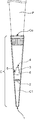
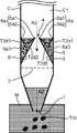
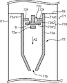
- FIG. 1 is an explanatory view illustrating the configuration of the suction tip according to the first embodiment of the present invention.
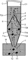
- FIG. 2A is an explanatory diagram illustrating a suction operation using the suction tip according to the first embodiment of the present invention.
- FIG. 2B is an explanatory diagram illustrating a discharge operation using the suction tip according to the first embodiment of this invention.
- FIG. 2C is an explanatory diagram illustrating a suction operation using a suction tip according to another example of the first embodiment of the present invention.
- FIG. 2D is an explanatory diagram illustrating a discharge operation using another example of the suction tip according to the first embodiment of the present invention.
- FIG. 2E is a plan view of another example of a suction tip according to the first embodiment of the present invention.
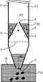
- FIG. 3A is an explanatory diagram illustrating a suction operation using the suction tip according to the second embodiment of the present invention.
- FIG. 3B is an explanatory diagram illustrating an ejection operation using the suction tip according to the second embodiment of the present invention.
- FIG. 3C is an explanatory diagram illustrating a suction operation using a suction tip according to another example of the second embodiment of the present invention.
- FIG. 3D is an explanatory diagram illustrating a discharge operation using the suction tip according to another example of the second embodiment of the present invention.
- FIG. 4 is an explanatory view for explaining the operation of the valve mechanism of the suction tip according to the third embodiment of the present invention.
- FIG. 5 is an explanatory view for explaining the operation of the valve mechanism of the suction tip according to the fourth embodiment of the present invention.
- FIG. 6 is an explanatory view of another example of the valve mechanism of the suction tip according to the fourth embodiment of the present invention.
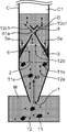
- FIG. 7 is an explanatory view of the valve mechanism of the suction tip according to the fifth embodiment of the present invention.
- FIG. 1 is an explanatory view illustrating the configuration of the suction tip according to the first embodiment of the present invention.
- the suction tip C is used by being attached to a suction pipette P that is a kind of suction device, and when the user operates the suction pipette P to suck the target, the suctioned target is suctioned temporarily. It is a laboratory instrument provided with a tubular passage C1 for holding.
- the suction pipette P is a suction device having a tip portion that enters the opening Co of the suction tip C.
- the suction pipette P sucks an object by generating a suction force from the suction port 1 of the suction tip C when the user operates a push button (not shown) with the suction tip C attached.
- the suction tip C of the present embodiment includes a distal end opening 1, a tubular passage C ⁇ b> 1 provided with a first membrane filter 2 (first sorting means), and a cone-shaped member 3. And having.
- first membrane filter 2 first sorting means
- cone-shaped member 3 cone-shaped member 3.
- the size (internal volume) of the suction tip C is not particularly limited, and a suction tip C having an internal volume of, for example, about 1 ⁇ L to 5 mL can be appropriately employed depending on the application.
- the thickness of the tube wall of the suction tip C is not particularly limited, but if it is too thin, the strength is lowered, and therefore it is preferably about 100 to 600 ⁇ m.
- the material constituting the suction tip C is not particularly limited as long as it is a material used for a normal suction tip.
- a resin such as polypropylene or polystyrene can be adopted as the material.
- the manufacturing method of the suction tip C is not particularly limited, and a conventionally known suction tip manufacturing method can be employed. For example, it is possible to employ a method in which the material is melted and injected into a molding die.
- the set M of objects includes a selection object T1 and a non-object T2.
- the type of collection M of objects includes a mixture of particles having various shapes and particle diameters, cell culture solutions containing various sizes of cells and contaminants, and cell treatment solutions.
- the set M of objects is a mixed slurry of particles of various shapes, and the suction chip C is used to suck and discharge the objects of a predetermined shape contained therein, the discharged particles are Corresponds to the sorting object T1.
- the set M of objects is a cell culture solution or a cell treatment solution containing cells and contaminants of various sizes, and is sucked using the suction tip C and discharges only cells of a predetermined shape.
- the discharged cells having a predetermined shape correspond to the sorting target T1.
- the selection target T1 to be sucked using the suction tip C of the present embodiment is preferably a living cell, more preferably a living cell aggregate.
- the suction chip C of this embodiment is used with cells derived from a living body as an object, only cells having a diameter larger than a predetermined diameter are selected from a set M of objects only by performing a series of operations of suction and discharge. It can be taken out as the object T1. At that time, since a disassembly operation such as removing the first membrane filter 2 described later is unnecessary, the user can efficiently perform the contamination without causing contamination in the field of bio-related technology or medicine in which contamination is particularly problematic. Work can be performed.
- a cell aggregate (spheroid spheroid) derived from a living body (including cell line origin) is generally formed by aggregating several to several hundred thousand individual cells.
- the cell agglomerates have various shapes such as a substantially spherical shape, a substantially square shape, a tubular shape, and an indefinite shape.
- the test result obtained using the cell aggregate derived from such a cell line considered the interaction between each cell inside the cell aggregate rather than the test result obtained using one cell.
- the bio-similar environment has been reconstructed, and the results of taking into account the functions of individual cells can be obtained, and the experimental conditions can be more consistent with the in-vivo environment.
- the suction tip C of the present embodiment only a cell aggregate having a diameter larger than a predetermined diameter is selected from the set M of objects only by performing a series of operations of suction and discharge. It can be taken out as T1.
- the suction chip C of the present embodiment can easily eliminate distorted cell agglomerates and the like, so that highly reliable results can be obtained in the fields of biotechnology and medicine.
- the tip opening 1 sucks or collects a set M (see FIG. 2A) of objects including a selection target T1 and a non-target T2 by operating a suction device such as a suction pipette to which a suction tip C is attached. It is an opening for discharging, and is formed at the distal end portion of the suction tip C as an end portion opening of a tubular passage C1 having an inner peripheral wall having a substantially circular cross section.
- the user immerses at least the tip opening 1 in a container in which the set M of objects is stored, and operates the suction device such as the suction pipette P to suck the set M of objects.
- the opening area of the tip opening 1 only needs to be larger than the diameter of the selection target T1, and may be appropriately adjusted according to the diameter of the selection target T1 to be sucked.
- the diameter of the tip opening 1 is about 150 to 1000 ⁇ m. Good.
- the shape of the tip opening 1 included in the suction tip C of the present embodiment may be a shape other than a circle and is not particularly limited.
- the shape of the tip opening 1 an optimum shape can be adopted as appropriate in accordance with the shape of the object.
- the user uses the suction tip C in which the shape of the tip opening 1 is narrow so that large spherical particles are obtained. Or flat particles can be prevented from being sucked from the tip opening 1.
- the tubular passage C ⁇ b> 1 is a passage formed inside the suction tip C, and the tip opening 1 is formed at the tip.
- the diameter of the tubular passage C1 is not particularly limited as long as the object can pass through.
- the diameter of the tubular passage C1 may be about 400 to 2000 ⁇ m.
- the collection M of the sucked objects advances through the tubular passage C1 to the downstream side in the suction direction (hereinafter may be simply referred to as the suction direction), and the user performs the suction.
- the tubular passage C1 is advanced to the upstream side in the suction direction (hereinafter sometimes simply referred to as the discharge direction).
- the selection target T1 and the non-target T2 included in the target set M reach the first membrane filter 2.
- the first membrane filter 2 allows only the non-target T2 out of the selection target T1 and the non-target T2 included in the set M of objects sucked from the tip opening 1 to pass through the selection target T1.
- the first membrane filter 2 is retained in the upstream side in the suction direction of the collection M of objects than the position where the first membrane filter 2 is disposed without passing through the filter.
- the first membrane filter 2 has a shape along the horizontal sectional shape of the tubular passage C ⁇ b> 1 and is joined to the inner peripheral wall of the tubular passage C ⁇ b> 1.
- the arrangement position of the tubular passage C1 is slightly upstream from the center position of the suction tip C in the suction direction of the collection M of objects.
- the first membrane filter 2 is a porous membrane provided with a through hole (first through hole) having a diameter smaller than the diameter of the sorting object T1.
- the opening area of the first through hole is not particularly limited.
- the user can employ the first membrane filter 2 provided with the first through hole having the optimum opening area according to the diameter of the sorting object T1 to be sorted.
- the diameter of the first through hole of the first membrane filter 2 can be set to about 100 ⁇ m.
- the thickness of the first membrane filter 2 is not particularly limited and is, for example, about 10 to 100 ⁇ m.
- the first membrane filter 2 is not bulky because of its small thickness, and can be provided in the tubular passage C1 of the suction tip C.
- the internal volume is not significantly reduced even when compared with a suction tip not provided with the first membrane filter 2. For this reason, when the first suction filter chip is provided with the first membrane filter 2, a measurement error due to a difference in internal volume or the like does not occur.
- the type of the first membrane filter 2 is not particularly limited.
- the first membrane filter 2 that is used for separation or filtration of substances such as proteins or cells can be used.
- a membrane filter made of nylon, cellulose, or the like, a glass fiber filter, or the like can be used.
- the suction chip C of the present embodiment may employ a mesh member in which first through holes are formed in a lattice shape as the first membrane filter, or may employ a mesh member having a fine hole. .
- the shape of the first through hole is not limited to a circle, and may be an ellipse or a polygon.
- the first through holes that connect these shapes are regularly or irregularly arranged. Different shapes may be employed.
- the substantially spherical selection target T1 does not pass through the first through hole.
- the cone-shaped member 3 captures the non-object T2 that has passed through the first membrane filter 2.
- the cone-shaped member 3 is provided downstream of the first membrane filter 2 in the suction direction of the collection M of objects in the tubular passage C1.
- the cone-shaped member 3 includes a passage hole 4 through which a set M of objects including the non-object T2 passes, and a storage unit 5 that stores the non-object T2 that has passed through.
- the storage part 5 of this embodiment functions when the suction tip C is used in a standing state with the suction port 1 facing downward.
- the cone-shaped member 3 has a tapered portion 6 that narrows the flow path of the sucked object set M in the suction direction of the target object set M.
- the taper portion 6 has an upstream end in the suction direction of the collection M of objects to be joined to the inner peripheral wall of the tubular passage C1, and the non-object T2 is attached to the narrowed end of the taper portion 6.
- a passage hole 4 through which the set M of objects to be included passes is formed.
- the ratio (diameter reduction ratio) by which the tapered portion 6 narrows the flow path of the sucked objects toward the suction direction of the collection M of objects may be constant, and the diameter reduction ratio gradually increases. It may vary as follows. That is, as shown in FIG. 2A, the inclination angle ⁇ of the tapered portion 6 may be constant or may vary.
- the inclination angle ⁇ is preferably 30 ° or more and 60 ° or less.
- the depth of the reservoir 5 formed between the outer peripheral wall of the cone-shaped member 3 and the inner peripheral wall of the tubular passage C1 becomes shallow, and the non-object T2 cannot be sufficiently stored. There is sex. As a result, there is a possibility that the non-object T2 that has not been stored flows back through the passage hole 4 and is discharged.
- the inclination angle is less than 30 °, it is necessary to increase the length of the cone-like member 3 in order to reduce the opening area of the passage hole 4 formed at the end of the tapered portion 6 of the cone-like member 3. Therefore, there is a possibility that the size of the suction tip C is increased and the convenience is deteriorated.
- the material of the cone-shaped member 3 is not particularly limited.
- a resin such as polypropylene or polystyrene can be adopted as the material.
- the cone-shaped member 3 may be formed by molding a metal such as aluminum.
- the passage hole 4 is formed at the end of the narrowed tapered portion 6.
- the passage hole 4 is a hole through which a set M of objects including the non-object T2 passes. It is preferable that the passage hole 4 has a shape that allows the non-object T2 to easily pass through when the collection of objects M is sucked, and can efficiently prevent the backflow of the non-object T2 during discharge of the collection of objects M. Therefore, the diameter of the passage hole 4 is preferably set to 100 to 500 ⁇ m, for example. When the diameter of the passage hole 4 is less than 50 ⁇ m, the flow of the collection M of objects at the time of suction is excessively suppressed, and the suction operation may not proceed smoothly. On the other hand, when the diameter of the passage hole 4 exceeds 500 ⁇ m, the non-object T2 tends to be mixed with the object set M during the discharge of the object set M and tends to flow backward.
- the shape of the passage hole 4 is not particularly limited. As the shape of the passage hole 4, various shapes such as a circle, an ellipse, and a polygon can be adopted.
- the number of passage holes 4 is not particularly limited. Since the passage hole 4 is formed at the end portion of the narrowed taper portion 6, the cone-shaped member 3 has a plurality of taper portions 6, and the plurality of taper portions 6 form a plurality of end portions. The through hole 4 may be formed at each end.
- the storage unit 5 stores the non-object T2 when discharging the set M of objects.
- the reservoir 5 is a space formed between the outer peripheral wall of the cone-shaped member 3 and the inner peripheral wall of the tubular passage C1.
- FIG. 2B when the collection M of objects is discharged from the tubular passage C1 by discharge, the object that has not been discharged into the space between the outer peripheral wall of the tapered portion 6 and the inner peripheral wall of the tubular passage C1.
- Set M remains.
- the non-object T2 passes through the passage hole 4 along the inner peripheral wall of the tapered portion 6 when the collection M of objects is sucked (see FIG. 2A), but almost all the non-object T2 is tapered when discharging. 6 settles in the storage part 5 along the outer peripheral wall 6 and is stored.
- the shape of the storage part 5 is not specifically limited. That is, as shown in FIGS. 2A and 2B, the shape of the reservoir 5 is a deep valley-like shape formed between the flat outer peripheral wall of the cone-shaped member 3 and the flat inner peripheral wall of the tubular passage C1. For example, as shown in FIG. 2C, even the gentle concave storage portion 5 a formed between the outer peripheral wall of the cone-shaped member 3 and the inner peripheral wall of the tubular passage C ⁇ b> 1 is not limited to the storage portion 5. Good.
- FIG. 2A is a schematic diagram for explaining how the set M of objects is sucked when the set M of objects is sucked using the suction tip C of the present embodiment.
- FIG. 2B is a schematic diagram illustrating a state in which the set M of target objects is discharged when the set M of target objects is discharged using the suction tip C of the present embodiment.
- a set M of target objects including a selection target T1 and a non-target T2 is obtained. Then, it is sucked from the suction port 1 and proceeds in the suction direction in the tubular passage C1.
- the set M of objects is stored in a container (not shown) such as a beaker.
- An arrow A1 indicates the traveling direction of the set M of objects that travels in the suction direction.
- the first membrane filter 2 does not pass the sorting target T1 out of the sorting target T1 and the non-target T2 included in the set M of targets arriving at the first membrane filter 2, and the non-target T2 Pass through.
- Reference symbol T1a indicates a selection object that travels in the A1 direction in the tubular passage C1
- reference symbol T2a indicates a non-target object that travels in the A1 direction in the tubular passage C1
- reference symbol T1b The sorting object that cannot pass through the first membrane filter 2 and remains in the tubular passage C1 is shown.
- the non-target T2 that has passed through the first membrane filter 2 further proceeds in the suction direction of the target set M together with the target set M from which the selection target T1 has been sorted and removed.
- Reference symbol T ⁇ b> 2 b indicates a non-object that has passed through the first membrane filter 2.
- the non-object T2b traveling in the suction direction of the collection M of objects travels along the inclined surface of the tapered portion 6 of the cone-shaped member 3 and passes through the passage hole 4 of the cone-shaped member 3.
- Reference symbol T ⁇ b> 2 c indicates a non-object that has passed through the passage hole 4.
- the set M of objects including the non-target T2 proceeds in the discharge direction of the target. To do.
- the set M of objects not including the non-object T2 passes through the passage hole 4, but most of the non-object T2 cannot pass through the passage hole 4 and proceeds to the storage unit 5.
- Reference symbol T ⁇ b> 2 d indicates a non-object that moves to the storage unit 5.
- the set M of objects not including the non-object T2 passes through the first sorting means and is discharged together with the sorting object T1.
- the suction tip P of the present embodiment can select and remove the non-object T2 with high accuracy.
- the suction chip C integrally provided with the first membrane filter 2 and the cone-shaped member 3 has been described as an example.
- the first membrane filter 2 and the cone-shaped member 3 are prepared as separate members. can do. That is, a filter unit including the first membrane filter 2 and a capturing unit including the cone-shaped member 3 are separately prepared and assembled into a conventional suction chip or attached to a conventional suction chip. Can do.
- the suction tip C of the present embodiment can discharge the selection target T1 having a diameter larger than that of the non-target T2 by the suction and discharge operations. Therefore, since the sorting target T1 required after discharge is not left in the suction tip C, the user does not need to disassemble the suction tip C, and contamination does not occur.
- the suction tip C is preferably disposable, but can be reused by disassembling and cleaning. In that case, in order to prevent contamination, it is preferable to sterilize various units by alcohol sterilization, UV irradiation, high-pressure steam sterilization, or the like before reuse.
- the operation when discharging the set M of objects is described with reference to FIG. 2B.
- the user does not prompt the discharge by pressing the push button (not shown) of the suction pipette.
- the sorting object T1 can be settling out from the tip opening 1 and taken out.
- the sorting object T1 introduced into the tubular passage C1 starts to settle in the direction of gravity.
- the surface tension does not act on the tip opening 1 unlike when exposed to the outside air. Therefore, even if the user does not perform the discharge operation, the selection target T1 falls from the tip opening 1.
- the user prompts the non-object T2c to settle in the storage unit 5 without passing through the opening hole, for example, by tilting the suction tip C.
- the suction chip C of the present embodiment can sufficiently sort the sorting target T1 only by performing a series of one suction and discharge operations, but the number of operations is limited to one. It may be performed several times. For example, after moving a suction pipette P equipped with the suction tip C of the present embodiment from a container (not shown) in which a set M of objects before sorting is stored, to another container, The suction pipette P equipped with the suction tip C of the present embodiment is operated and transferred to another container. Thereby, the user can improve the sorting accuracy of the sorting target T1 when only the sorting target T1 cannot be completely sorted by one suction and discharge operation.
- the suction tip C of the present embodiment may be provided with a plurality of cone-shaped members in the suction tip C.
- another cone-shaped member can be disposed on the downstream side in the suction direction of the passage hole 4 of the cone-shaped member 3 of the present embodiment.
- the non-object T2 that has passed through the passage hole of another cone-shaped member during suction flows backward through the passage hole of another cone-shaped member during discharge, the non-object T2 is provided on the upstream side thereof.
- the possibility of passing through the passage hole 4 of the cone-shaped member 3 is extremely low. The user can further improve the sorting accuracy of the sorting target T1.
- the user sets the position of the passage hole of each cone-shaped member in the tubular passage C1 of the suction tip C. In the axial direction, it is preferably arranged at a position that is not coaxial.
- a sorting member D may be arranged on the downstream side of the passage hole 4 of the cone-shaped member 3, and the non-object T ⁇ b> 2 that has passed through the passage hole 4 may be sorted.
- reference symbol T2c1 indicates a non-object distributed to the left and right by the distribution member D
- reference symbol A1a indicates the distribution direction.
- the sorting member D is a conical member, and is arranged in an inverted conical shape so that the top portion is located on the downstream side of the passage hole 4.
- the distribution member D distributes the liquid flow including the non-object T2 that has passed through the passage hole 4 in the circumferential direction by the conical slope of the distribution member D, and advances the liquid flow toward the inner wall of the tubular passage C1.
- the shape of the sorting member D is not particularly limited, and may be any shape as long as the non-object T2 that has passed through the through hole 4 can be sorted in the direction of the inner wall of the tubular passage C1, and may be, for example, a truncated pyramid shape.
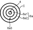
- a reverse tapered portion 6 a can be provided on at least one of a part of the outer peripheral wall of the cone-shaped member 3 and a part of the inner peripheral wall of the tubular passage 3.
- path 3 is demonstrated.
- the reverse tapered portion 6a includes an inner tapered piece 6a1 and an outer tapered piece 6a2.
- FIG. 2D is an explanatory diagram for explaining an operation of ejection using the suction tip of another example of the present embodiment
- FIG. 2E is a plan view of another suction tip of the present embodiment.
- the inner taper piece 6 a 1 is a member that is joined to the outer peripheral wall of the cone-shaped member 3 at the downstream end portion and that circulates around the outer peripheral wall of the cone-shaped member 3.
- the inner taper piece 6a1 has a slope that promotes the settling of the non-object (non-object T2d1) during ejection.
- the outer taper piece 6a2 is joined to the inner peripheral wall of the tubular passage C1 at the downstream end, and is a member that goes around the inner peripheral wall of the tubular passage C1.
- the outer taper piece 6a2 has a slope that promotes the settling of the non-object (non-object T2d1) during ejection.
- the horizontal position of the joint between the inner tapered piece 6a1 and the outer peripheral wall of the cone-shaped member 3 (the upper edge of the inner tapered piece 6a1) is the joint between the outer tapered piece 6a2 and the inner peripheral wall of the tubular passage C1 (outer tapered piece).
- the horizontal position of the upper edge of 6a2 is approximately the same.
- the upstream end of the inner tapered piece 6a1 and the upstream end of the outer tapered piece 6a2 are close to each other and form an annular passage hole 6a3.
- the non-target T2 has its flow path narrowed by the inner tapered piece 6a1 and the outer tapered piece 6a2, passes through the passage hole 6a3, and settles in the storage unit 5.
- Reference symbol T2d2 indicates a non-object that has passed through the passage hole 6a3.
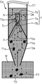
- FIG. 3 is an explanatory view for explaining the suction and discharge operations using the suction tip Ca of the second embodiment of the present invention.
- FIG. 3A is a collection of objects using the suction tip Ca of the present embodiment. It is a schematic diagram explaining a mode that the set M of a target object is attracted
- FIG. 3B is a schematic diagram for explaining how the set M of objects is discharged when the set M of objects is discharged using the suction tip Ca of the present embodiment.
- the suction tip Ca of the second embodiment further includes a valve mechanism 7 and a second membrane filter 8 (second sorting means) on the downstream side in the suction direction of the collection M of objects from the passage hole 4. Except for the provision, it is the same as the suction tip C of the first embodiment. Therefore, description other than a difference is abbreviate
- the valve mechanism 7 is disposed in the vicinity of the passage hole 4 and is for the purpose of differentiating the flow path of the set of objects M at the time of suction and at the time of discharge in order to capture non-objects more reliably in the reservoir. Is provided. As shown in FIG. 3A, the valve mechanism 7 draws the non-object T2c that has passed through the passage hole 4 before the upstream opening 7b of the valve mechanism at the time of suction of the set M of objects. A path toward the second membrane filter 8 is provided by diverting to the outer side in the circumferential direction (arrow A4 direction). Further, as shown in FIG.
- the valve mechanism 7 causes the liquid component contained in the object set M that has passed through the second membrane filter 8 to be discharged to the downstream side of the valve mechanism when discharging the object set M. It introduce
- the valve mechanism 7 includes a main body 7a having a passage therein, an upstream opening 7b and a downstream opening 7c provided in the main body 7a, and a lid 7d.
- the main body 7a has an internal passage through which liquid components contained in the set M of objects pass during ejection.
- the main body 7a moves up and down in the tubular passage C1 according to the flow of the set of objects M when the set of objects M is sucked and discharged.
- the main body portion 7a is provided with openings on the top and bottom.
- the material constituting the main body portion 7a is not particularly limited, and for example, a resin such as polypropylene or polystyrene can be employed. In addition, a metal such as aluminum may be molded to form the main body portion 7a.
- the upstream opening 7 b is an opening at one end of the main body 7 a, and the opening area is smaller than the passage hole 4 of the cone-shaped member 3.
- the downstream opening 7c is an opening at the other end of the main body 7a.
- the main body 7a moves in the suction direction as shown in FIG. 3A. Therefore, the upstream opening 7b is separated from the passage hole 4 of the cone-shaped member 3 and the upstream opening 7b. Further, the downstream opening 7c is closed in contact with a lid 7d described later. Therefore, the set M of objects including the non-object T2 does not flow from the upstream opening 7b into the main body 7a, but is diverted to the outer side in the circumferential direction of the passage hole 4 before the upstream opening 7b (arrow). A4 direction).
- the main body 7a moves in the discharge direction as shown in FIG. 3B. Therefore, the upstream opening 7 b allows the tip portion to enter the passage hole 4 of the cone-shaped member 3 and communicates the internal passage of the main body portion 2 a and the upstream region of the passage hole 4 of the taper portion 6. Further, the downstream opening 7c is separated from a lid 7d described later and opened when the main body 7 moves. Therefore, the set M of objects including the non-object T2 is introduced into the main body 7a from the opened downstream opening 7c (in the direction of arrow A6), and the upstream region of the passage hole 4 from the upstream opening 7b. Discharged. At this time, the non-object T2d stored in the tapered portion 6 does not merge with the set M of discharged objects.
- the opening area of the upstream opening 7b is not particularly limited as long as the tip can enter the passage hole 4 described above.
- the opening area of the passage hole 4 is 7500 to 200,000 ⁇ m 2
- the opening area of the upstream opening 7b can be about 3500 to 100,000 ⁇ m 2 .
- the shape of the tip including the upstream opening 7b is reduced in diameter upstream so that the opening area is smaller than the cross-sectional area of the main body 7a. Therefore, when the main body 7a moves upstream during discharge, the front end including the upstream opening 7b can easily enter the passage hole 4, and is introduced into the main body 7a from the downstream opening 7c. It is easy to discharge the set M of the target objects from the upstream opening 7b.
- the lid 7d abuts on the downstream opening 7c of the main body 7a that has moved downstream to close the downstream opening 7c when the set M of objects is sucked.
- the lid 7d moves away from the downstream opening 7c because the main body 7a moves upstream when discharging the set M of objects. Open.
- the material constituting the lid portion 7d is not particularly limited, and for example, a resin such as polypropylene or polystyrene can be employed.
- a lid 7d may be formed by molding a metal such as aluminum. As described above, the lid 7d contacts the downstream opening 7c and closes the downstream opening 7c. Therefore, it is preferable that the resin material has a sealing property.
- the valve mechanism 7 is provided with a second membrane filter 8 on the outer periphery.
- the second membrane filter 8 does not pass the non-object T2 from the set M of objects including the non-target T2, but allows only the liquid components constituting the set M of objects to pass.
- the second membrane filter 8 is provided between the upstream opening 7b and the downstream opening 7c.
- the second membrane filter 8 is a donut-shaped membrane body, the outer peripheral edge of which is joined to the inner peripheral wall of the tubular passage C1, and the inner peripheral edge is the main body portion of the valve mechanism 7.
- the outer peripheral wall of 7a is also joined.
- the second membrane filter 8 is provided in the suction path through which the set M of objects that have passed through the passage hole 4 of the tapered portion 6 passes during suction.
- the position of the second membrane filter 8 is The position is not particularly limited. Another example of the position of the second membrane filter 8 will be described in detail later.
- the second membrane filter 8 is a porous membrane provided with a through hole (second through hole) having a diameter smaller than that of the non-target T2.
- the opening area of the second through hole is not particularly limited.
- the user can employ the second membrane filter 8 provided with the second through-hole having the optimum opening area according to the diameter of the non-object T2 to be selected.
- the diameter of the second through hole of the second membrane filter 8 can be set to about 10 ⁇ m.
- the thickness of the second membrane filter 8 is not particularly limited and is, for example, about 5 to 20 ⁇ m. Thus, since the second membrane filter 8 is small in thickness, it is not bulky and can be provided in the suction pipette.
- the internal volume is not significantly reduced even when compared with a suction tip not provided with the second membrane filter 8. Therefore, when the second membrane filter 8 is provided on the conventional suction tip or the suction tip C of the first embodiment, a measurement error due to a difference in internal volume or the like does not occur.
- the type of the second membrane filter 8 is not particularly limited, and the same type as the first membrane filter 2 described above can be adopted. Moreover, it does not specifically limit about the shape of a 2nd through-hole, The thing similar to the 1st through-hole of the above-mentioned 1st membrane filter 2 is employable.
- valve mechanism 7 when suctioning and discharging using the suction tip Ca of the present embodiment will be described.
- the main body 7a of the valve mechanism 7 sucks the collection M of objects. Move in the direction.
- An arrow A3 indicates the moving direction of the main body 7a.
- the downstream-side opening 7c comes into contact with the lid 7d by the movement of the main body 7a and is closed.
- the set M of target objects does not flow into the main body 7a from the upstream opening 7b but is diverted to the outer side in the circumferential direction of the passage hole 4 (in the direction of arrow A4) before the upstream opening 7b.
- the set M of objects including the non-object T2 reaches the second membrane filter 8 as the user continues to suck.
- the second membrane filter 8 does not pass through the non-target object T2, but allows only the liquid component constituting the set M of target objects to pass therethrough.
- Reference symbol T2e indicates a non-object that cannot pass through the second membrane filter 8 and stays in the vicinity of the second membrane filter 8.
- the main body portion 7a of the valve mechanism 7 moves in the discharge direction of the collection M of the objects.
- An arrow A5 indicates the moving direction of the main body 7a.
- the downstream opening 7c is separated from the lid 7d that has been in contact and is opened.
- the tip including the upstream opening 7 b enters the passage hole 4 of the cone-shaped member 3.
- the liquid component constituting the set of objects M that has passed through the second membrane filter 8 flows into the main body 7a from the downstream opening 7c (in the direction of arrow A6) and passes through the main body 7a.
- the ink is discharged from the upstream opening 7b and discharged in the direction of the arrow A2.
- the non-object T2e staying in the vicinity of the second membrane filter 8 settles in the storage unit 5 according to gravity when the user finishes the suction.
- the distal end portion of the body portion 7a of the valve mechanism 7 enters the passage hole 4 and the passage hole 4 is closed. Therefore, the non-object T2 does not flow backward through the passage hole 4 and is not discharged.
- the suction tip Ca of the present embodiment includes the valve mechanism 7 and the second membrane filter 8.
- the valve mechanism 7 moves the main body portion 7a to allow the tip of the upstream opening 7b to enter the passage hole 4 and close the passage hole 4. Therefore, in the suction chip Ca of the present embodiment, even if the non-object T2 that has not been stored in the storage unit 5 is floating in the set M of objects, the floating non-object T2 is It is possible to prevent the flow through the passage hole 4 from flowing back and joining the sorting object T1.
- the suction tip Ca of the present embodiment communicates the tip including the upstream opening 7b and the passage hole 4 of the cone-shaped member 3 at the time of discharge, so that the collection of objects that have passed through the second membrane filter 8 Only the liquid component of M passes through the passage hole 4 and is discharged together with the sorting object T1 sorted by the first membrane filter 2.
- the suction tip Ca of the present embodiment communicates the tip including the upstream opening 7b and the passage hole 4 of the cone-shaped member 3 at the time of discharge, so that the collection of objects that have passed through the second membrane filter 8 Only the liquid component of M passes through the passage hole 4 and is discharged together with the sorting object T1 sorted by the first membrane filter 2.
- the cone-shaped member 3 is used as the capturing mechanism (capturing means), and the storage portion 5 is formed between the outer peripheral wall of the tapered portion 6 of the cone-shaped member and the inner peripheral wall of the tubular passage C1.
- the form of storing the non-object T2 is not particularly limited.
- a saucer-like member S provided on the downstream side of the first membrane filter 2 can be employed as the capturing mechanism.
- the saucer-like member S has a circular shape and includes an opening hole Sa and a wall portion Sa provided around the opening hole Sa.
- the non-object T2b passes through the opening hole Sa during suction.
- the non-object that has passed through is blocked by the second membrane filter 8.
- the asymmetric object (non-object T2e1) settles on the tray of the tray-like member S at the time of discharge.
- Wall part Sa1 is provided in order for non-object T2e1 which settled in the saucer-like member S to be stored stably.
- valve mechanism 7 moves downstream during discharge.
- the distal end including the upstream opening 7b makes a part of the outer periphery of the distal end abut against the wall Sa1 and enters the opening hole Sa to close the opening hole Sa.
- the non-object T2b does not flow backward through the opening hole Sa.
- 3C and 3D show the case where the wall portion Sa1 is provided around the opening hole Sa, the wall portion Sa1 is not essential.
- the suction chip Ca integrally including the second membrane filter 8 and the valve mechanism 7 has been described as an example.
- the second membrane filter 8 and the valve mechanism 7 should be prepared as separate members. Can do. That is, a filter unit including the second membrane filter 8 and a valve mechanism 7 unit including the valve mechanism 7 may be prepared, and a suction tip unit connectable to these units may be prepared. The prepared unit can be easily assembled with the suction tip Ca of the present embodiment by being configured to be adhered or fitted. If necessary, only part of the valve mechanism 7 may be provided as a unit, or part of the valve mechanism 7 may be provided integrally with the second membrane filter 8.
- a unit in which only the lid portion 7d of the valve mechanism 7 is provided integrally with the suction tip Ca and the outer peripheral wall of the main body portion 7a is joined to the second membrane filter may be prepared.
- a hole in which the body portion 7a of the valve mechanism 7 can move up and down is provided in the center of the second membrane filter 8, and the valve mechanism 7 can move up and down during suction and discharge. Good.
- FIG. 4 is an explanatory view for explaining the operation of the valve mechanism 71 of the suction tip according to the third embodiment of the present invention.
- the suction tip of the third embodiment is the same as the suction tip of the second embodiment except that the structure and operation of the valve mechanism 71 are different. Therefore, description other than a difference is abbreviate
- the valve mechanism 71 has a swing type reversely supported valve structure.
- the valve mechanism 71 includes a main body 71a, an upstream opening 71b, a downstream opening 71c, and a lid 71d. Since the configuration is the same as that of the valve mechanism 7 described in the second embodiment except for the lid portion 71d, description thereof is omitted.
- One end of the lid 71d is rotatably attached to the inner peripheral wall of the main body 71a in the vicinity of the downstream opening 71c.
- lid portion 71d there is no particular limitation as a method for rotatably attaching one end of the lid portion 71d to the inner peripheral wall of the main body portion 71a.
- the lid 71d and the inner peripheral wall of the main body 71a can be rotatably attached using a hinge.
- the user pushes the push button (see FIG. 1) of the suction pipette P with the suction tip C attached to the tip of the suction pipette P (see FIG. 1) which is a suction device.
- the air in the tubular passage C1 of the suction tip C is discharged by pushing in (not shown).
- air is directed in the suction direction of the collection M of objects in the internal passage of the main body 71a of the valve mechanism 71.
- the lid portion 71d rotates in a direction in which it abuts against the abutment piece 71e (arrow A7 direction), abuts against the abutment portion 71e, and closes the downstream opening 71c.
- the abutting portion 71e is a member protruding from the inner peripheral wall of the internal passage of the main body portion 71a, and is provided in the vicinity of the downstream opening 71c.
- the contact portion 71e stops the rotation of the lid portion 71d by contacting the rotating lid portion 71d.
- the protruding length of the abutting portion 71e that abuts on the rotating lid portion 71d is not particularly limited as long as the end portion of the rotating lid portion 71d abuts.
- the main body 71a moves, and the tip including the upstream opening 71b enters the passage hole 4 (see FIG. 3B) of the cone-shaped member 3.
- the liquid component constituting the set M of objects flows in the direction of arrow A2, and rotates in the direction (arrow A8 direction) that pushes open the lid 71d and opens the downstream opening 71c.
- the liquid component constituting the set M of the objects flows into the internal passage of the main body 71a from the opened downstream opening 71c and is discharged from the upstream opening 71b.
- the cover part 71d rotated by the flow of the set M of objects was illustrated, the cover part 71d is not limited to this.
- an elastic member such as a compression spring may be attached to the lid portion 71d so that the downstream side opening portion 71c is always closed during or before suction.
- the stress (stress in the direction of arrow A7) applied to the lid 71d by an elastic member such as a compression spring is such that the flow of the set M of objects during discharge causes the downstream opening 71c to be opened. It is set smaller than the stress applied to (the stress in the direction of arrow A8).
- a sealing material at a contact portion between the lid 71d and the contact portion 71e. It does not specifically limit as a sealing material, Sealing materials, such as natural rubber, a synthetic rubber, and Teflon (trademark), are employable.
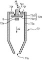
- FIG. 5 is an explanatory view for explaining the operation of the valve mechanism 72 of the suction tip according to the fourth embodiment of the present invention.
- the suction tip of the fourth embodiment is the same as the suction tip of the second embodiment except that the structure and operation of the valve mechanism 72 are different. Therefore, description other than a difference is abbreviate
- the valve mechanism 72 has a lift-type counter-support valve structure.
- the valve mechanism 72 includes a main body 72a, an upstream opening 72b, a downstream opening 72c, and a lid 72d. Since the configuration is the same as that of the valve mechanism 7 described in the second embodiment except for the lid portion 72d, description thereof is omitted.
- the lid 72d is provided to be movable up and down in the vicinity of the downstream opening 72c.
- the lid portion 72d includes a substantially disc-shaped lid portion main body 72d1 and a shaft 72d2 connected to the lid portion main body 72d1.
- the lid main body 72d1 has a cross-sectional shape covering the downstream opening 72c.
- the diameter of the cross section of the lid main body 72d1 is smaller than the inner diameter of the internal passage of the main body 72a. Therefore, the lid 72d can move up and down in the internal passage of the main body 72a, and the downstream opening 72c can be closed.
- the shaft 72d2 is a member that functions as a guide when the lid portion 72d moves up and down (in the directions of arrows A9 and A10) in the internal passage of the main body portion 72a.
- the liquid component contained in the target object set M flows into the internal passage of the main body 72a from the downstream opening 72c. Therefore, the diameter of the shaft 72d2 is smaller than the opening area of the downstream opening 72c so that the gap S can be formed to such an extent that the liquid component of the set M of objects can sufficiently pass through the downstream opening 72c.
- the shaft 72d2 may be formed integrally with the lid main body 72d1, or may be formed integrally by joining or the like after being prepared as a separate body.
- the user when the user performs a suction operation, the user attaches the suction tip to the tip of a suction pipette (not shown) that is a suction device, and the suction pipette The air in the internal passage of the suction tip is discharged by pushing the push button.
- the abutting portion 72f is a member projecting from the internal passage of the main body 72a, and is provided in the vicinity of the downstream opening 72c.
- the abutting part 72f stops the movement of the lid part 72d by coming into contact with the lid part 72d moving upward.
- the protruding length of the abutting portion 72f is not particularly limited as long as the end of the lid main body 72d1 abuts.
- the main body 72a moves, and the tip including the upstream opening 72b enters the passage hole 4 (see FIG. 3B) of the cone-shaped member 3.
- the liquid constituting the set M of objects flows in the discharge direction (arrow A2 direction), and moves the lid 72d downward (arrow A10 direction).
- the liquid component constituting the set M of the objects flows into the internal passage of the main body 72a from the clearance S of the downstream opening 72c opened by the movement of the lid 72d, and is discharged from the upstream opening 72b. .
- the lid portion 72d that has moved downward comes into contact with the contact portion 72e and stops.
- the abutting part 72e stops the movement of the lid part 72d by coming into contact with the lid part 72d moving downward.
- the abutting part 72e is a member protruding from a part of the internal passage of the main body part 72a.
- a seal material at the contact portion between the end of the lid main body 72d1 and the contact portion 72f. It does not specifically limit as a sealing material, Sealing materials, such as natural rubber, a synthetic rubber, and Teflon (trademark), are employable.
- valve mechanism 72 including the lid body 72d1 having a cross-sectional shape covering the downstream opening 72c is exemplified, but the cross-sectional shape of the lid body 72d1 is not particularly limited.
- the lid 72d having a shape similar to that of the cone-shaped member 3 described in detail in the first embodiment is adopted, and the engaged surface with which the tapered portion 6 of the cone-shaped member 3 is engaged without a gap is abutting piece. 72f may be provided.
- the position of the second membrane filter 8 is not limited to between the upstream opening and the downstream opening.
- the second membrane filter (second membrane filter 8 a) has one extension portion 71 a 1 when the extension portion 71 a 1 is provided in a part of the main body portion 71 a. May be provided between the portion and the upstream opening 71b.
- the outer peripheral edge of the second membrane filter 8a is joined to the inner peripheral wall of the tubular passage C1
- the inner peripheral edge of the second membrane filter 8a is joined to the outer peripheral wall of the extending portion 71a1.
- the position of the second membrane filter 8a is such that the liquid component of the collection of objects that have passed through the second membrane filter 8a at the time of suction is not mixed with the non-object at the time of discharge, and the main body of the valve mechanism 7 Any position can be used as long as it can pass through 71a.
- the suction tip of the fifth embodiment is the same as the suction tip of the fourth embodiment except that the structure and operation of the valve mechanism 73 are different. Therefore, description other than a difference is abbreviate
- the suction tip valve mechanism 73 of the present embodiment includes a main body 73a, an upstream opening 73b, a downstream opening 73c, and a lid 73d.
- the lid portion 73d includes a lid portion main body 73d1 and a shaft 73d2 connected to the lid portion main body 73d1.
- the function of the contact portion 73e is the same as that of the contact portion 72e described above in the fourth embodiment.
- the main body 73a of the valve mechanism 73 of the present embodiment is joined to the inner wall of the tubular passage C1 on the downstream side of the first membrane filter 2.
- a passage hole 73a1 is formed in the side peripheral wall of the main body 73a.
- the reservoir 5b is a space formed between the outer peripheral wall of the main body 73a and the inner peripheral wall of the tubular passage C1.
- the lid 73d moves downstream, closes the downstream opening 73c, and opens the passage hole 73a1.
- An arrow A11 indicates the moving direction of the lid portion 73d during suction.
- the non-object T2 that has passed through the first membrane filter 2 passes through the passage hole 73a1.
- Reference symbol T2f indicates a non-object that has passed through the passage hole 73a1.
- the second membrane filter 8b does not pass the non-object T2f.
- the diameter of the lid portion main body 73d1 of the lid portion 73d is such that the liquid component flowing in from the downstream opening 73c passes through the inside of the main body 73a and is discharged from the upstream opening 73b during discharge. It is formed smaller than the inner diameter of the inner passage.
- the lid 73d moves upstream, opens the downstream opening 73c, and opens the passage hole 73a1 on the side surface of the lid main body 73d1. Close.
- An arrow A12 indicates the moving direction of the lid portion 73d during discharge.
- the liquid component that has passed through the second membrane filter 8b is introduced from the opened downstream opening 73c, and the liquid component is discharged from the upstream opening 73a. Further, the non-object T2f settles in the storage part 5b. As described above, since the passage hole 73a1 is closed at the time of discharge, the non-object T2g does not flow backward through the passage hole 73a1.
- the passage hole 73a1 is provided in the lateral direction
- the direction in which the passage hole 73a1 is formed is not particularly limited.
- the passage hole 73a1 may be provided in a direction that is inclined so as to be inclined downward from the inner periphery to the outer periphery of the main body portion 73a.
- the non-object T2f that has passed through the passage hole 73a1 and reached the second membrane filter 8b settles in the storage portion 5b, it is difficult for the non-object T2f to flow backward through the passage hole 73a1.
- the liquid component that has passed through the second membrane filter 8b at the time of ejection has been described as an example when it passes through the downstream opening 73c.
- the liquid component discharge path is not particularly limited.
- a through hole 73d3 penetrating the lid main body (lid main body 73d2) in the vertical direction is provided in the lid main body 73d2 as a liquid component discharge path, so that the liquid component is Alternatively, it may be configured to pass through the through-hole 73d3.
- the downstream opening of the through-hole 73d3 abuts on the inner periphery of the main body 73a during suction, so that the non-object passes through the passage hole 73a1.
- a through hole 73a2 that penetrates the main body 73a is provided in a part (for example, the upper surface) of the main body 73a so that the liquid component passes through the through hole 73a2. It may be configured. Since the upstream opening of the through-hole 73a2 contacts the lid main body 73d3 during suction, the non-object passes through the passage hole 73a1.
- a suction tip includes a tip opening that sucks or discharges a collection of objects including a sorting object and a non-target, and sorting included in the collection of objects sucked from the tip opening.
- a tubular passage provided with a first sorting means for sorting an object and a non-object and allowing the non-object to pass through, and suction of the collection of the objects of the tubular passage more than the first sorting means
- a storage part for storing.
- the first sorting means is preferably a membrane filter having a plurality of through holes on the surface.
- the present invention is not bulky even if it is attached to the suction tip by adopting such a configuration.
- membrane filters having various pore diameters are prepared and a membrane filter is selected according to the shape of the sorting object, sorting objects having various shapes can be sorted.
- the capturing means has a tapered portion that narrows the flow path of the sucked objects toward the downstream side in the suction direction of the collection of the objects, and the passage hole is formed at the end of the narrowed tapered section. Is preferably formed.
- the present invention by adopting such a configuration, it is easy to introduce the non-object that has passed through the first sorting means into the passage hole. As a result, the non-object is easily stored in the storage part after passing through the passage hole, and the suction chip sorting ability can be improved.
- the tubular passage is a passage provided with an inner peripheral wall having a substantially circular cross section, and the capturing means has an upstream end in the suction direction of the collection of the objects joined to the inner peripheral wall, and the object.
- a conical member in which the passage hole is formed on the downstream side in the suction direction of the assembly, and the storage portion is between the outer peripheral wall of the cone-shaped member of the capturing means and the inner peripheral wall of the tubular passage. A space to be formed is preferable.
- the present invention makes it easy to introduce a non-object into the passage hole when the set of objects is sucked, and the non-object is placed on the outer peripheral wall of the cone-shaped member when discharging the set of objects. Since it is easy to introduce to a storage part along, a non-object can be removed efficiently.
- the tubular passage further comprises a valve mechanism provided on the downstream side in the suction direction of the collection of the objects with respect to the passage hole, and a second sorting means, the valve mechanism having a passage inside.
- An upstream opening provided in the main body and upstream in the suction direction of the collection of objects; provided in the main body and provided downstream in the suction direction of the collection of objects.
- a downstream opening, and a lid that closes the downstream opening when the set of objects is sucked and opens the downstream opening when the set of objects is discharged
- the second sorting means is provided on the downstream side of the upstream opening and upstream of the downstream opening, while sorting the non-object from the set of objects passing through the passage hole. It is preferable to pass the set of objects.
- the present invention floats when non-objects that have not passed through the passage hole and are not stored in the storage part are floating in the collection of objects. It is possible to prevent the non-objects flowing back and joining the sorting objects.
- the lid closes the downstream opening by abutting the downstream opening of the main body that moves to the downstream side in the suction direction of the collection of objects when the collection of the objects is sucked,
- the main body moves to the upstream side in the suction direction of the collection of objects when discharging the collection of objects, and opens the closed downstream opening, and includes the upstream opening.
- the front end portion is made to enter the passage hole of the capturing unit, and the set of the objects that have passed through the second sorting unit is discharged from the upstream opening.
- the present invention allows the tip portion including the upstream opening to communicate with the passage hole of the capturing means during discharge, so that the non-object that has not passed through the second sorting means. Since the path for passing through the passage hole is blocked, the sorting ability of the suction tip can be improved.
- the selection object is a living cell.
- the present invention can contribute to the improvement of work efficiency in the fields of bio-related technology and medicine in which contamination is particularly problematic by adopting such a configuration.
- the selection object is a cell aggregate derived from a living body.
- the present invention can obtain a result that takes into account the function of individual cells, and can further improve the experimental conditions in vivo than the test results obtained using a single cell. Can be matched to the conditions in line with the environment.
- a suction chip capable of obtaining highly reliable results in the fields of biotechnology and medicine Can do.
Abstract
Description
以下、本発明の第1の実施形態の吸引チップについて、図面を参照しながら詳細に説明する。図1は、本発明の第1の実施形態の吸引チップの構成を説明する説明図である。 (First embodiment)
Hereinafter, the suction tip according to the first embodiment of the present invention will be described in detail with reference to the drawings. FIG. 1 is an explanatory view illustrating the configuration of the suction tip according to the first embodiment of the present invention.
吸引チップCは、吸引装置の1種である吸引ピペットPに装着して使用され、ユーザが吸引ピペットPを操作して対象物を吸引する際に、吸引した対象物を吸引して一時的に保持するための管状通路C1を備えた実験器具である。なお、吸引ピペットPは、吸引チップCの開口部Coに進入する先端部を有する吸引装置である。吸引ピペットPは、吸引チップCを装着した状態でユーザがプッシュボタン(図示せず)を操作することにより、吸引チップCの吸引口1から吸引力を発生させて、対象物を吸引する。 <About suction tip C>
The suction tip C is used by being attached to a suction pipette P that is a kind of suction device, and when the user operates the suction pipette P to suck the target, the suctioned target is suctioned temporarily. It is a laboratory instrument provided with a tubular passage C1 for holding. The suction pipette P is a suction device having a tip portion that enters the opening Co of the suction tip C. The suction pipette P sucks an object by generating a suction force from the
対象物の集合Mは、選別対象物T1と非対象物T2とを含む。対象物の集合Mの種類としては特に限定されないが、種々の形状や粒子径を有する粒子の混合物、種々の大きさの細胞や夾雑物を含んだ細胞培養液や細胞処理液などが挙げられる。たとえば、対象物の集合Mが、種々の形状の粒子の混合スラリーであり、吸引チップCを用いてその中に含まれる所定の形状の対象物を吸引し、吐出する場合、吐出された粒子が選別対象物T1に該当する。同様に、対象物の集合Mが、種々の大きさの細胞や夾雑物を含んだ細胞培養液や細胞処理液であり、吸引チップCを用いて吸引し、所定の形状の細胞のみを吐出する場合、吐出された所定の形状の細胞が選別対象物T1に該当する。 <About the set M of objects>
The set M of objects includes a selection object T1 and a non-object T2. There are no particular limitations on the type of collection M of objects, and examples include a mixture of particles having various shapes and particle diameters, cell culture solutions containing various sizes of cells and contaminants, and cell treatment solutions. For example, when the set M of objects is a mixed slurry of particles of various shapes, and the suction chip C is used to suck and discharge the objects of a predetermined shape contained therein, the discharged particles are Corresponds to the sorting object T1. Similarly, the set M of objects is a cell culture solution or a cell treatment solution containing cells and contaminants of various sizes, and is sucked using the suction tip C and discharges only cells of a predetermined shape. In this case, the discharged cells having a predetermined shape correspond to the sorting target T1.
先端開口部1は、ユーザが吸引チップCを装着した吸引ピペット等の吸引装置を操作することにより選別対象物T1と非対象物T2とを含む対象物の集合M(図2A参照)を吸引または吐出するための開口であり、吸引チップCの先端部において、断面が略円形の内周壁を備えた管状通路C1の端部開口として形成されている。ユーザは、少なくとも先端開口部1を対象物の集合Mが貯留された容器に浸漬し、吸引ピペットP等の吸引装置を操作して対象物の集合Mを吸引する。 <About the
The
管状通路C1は、吸引ピペットP等の吸引装置を用いて対象物の集合Mを吸引する際に、対象物の集合Mが通過する。管状通路C1は、図1に示されるように、吸引チップCの内部に形成された通路であり、先端部に先端開口部1が形成されている。 <About the tubular passage C1>
When the collection M of objects is sucked into the tubular passage C1 using a suction device such as the suction pipette P, the collection M of objects passes. As shown in FIG. 1, the tubular passage C <b> 1 is a passage formed inside the suction tip C, and the
第一の膜フィルタ2は、先端開口部1から吸引された対象物の集合Mに含まれる選別対象物T1と非対象物T2とのうち、非対象物T2のみを通過させ、選別対象物T1を通過させずに第一の膜フィルタ2が配置された位置よりも、対象物の集合Mの吸引方向の上流側に滞留させる。第一の膜フィルタ2は、図1に示されるように、管状通路C1の水平断面形状に沿った形状を有し、管状通路C1の内周壁に接合されている。管状通路C1の配置位置は、吸引チップCの中央位置から、やや対象物の集合Mの吸引方向の上流側である。 <About the
The
コーン状部材3(捕捉機構、捕捉手段)は、第一の膜フィルタ2を通過した非対象物T2を捕捉する。コーン状部材3は、管状通路C1において、第一の膜フィルタ2よりも対象物の集合Mの吸引方向の下流側に設けられる。コーン状部材3は、非対象物T2を含む対象物の集合Mを通過させる通過孔4と、通過した非対象物T2を貯留する貯留部5を有する。なお、本実施形態の貯留部5は、吸引チップCが吸引口1を下方にして立設状態で使用される場合に機能する。 <About the cone-shaped
The cone-shaped member 3 (capturing mechanism, capturing unit) captures the non-object T2 that has passed through the
以下に、本発明の第2の実施形態の吸引チップCaについて、図面を参照しながら詳細に説明する。図3は、本発明の第2の実施形態の吸引チップCaを用いた吸引および吐出の動作を説明する説明図であり、図3Aは、本実施形態の吸引チップCaを用いて対象物の集合Mを吸引した際に、対象物の集合Mが吸引される様子を説明する模式図である。図3Bは、本実施形態の吸引チップCaを用いて対象物の集合Mを吐出した際に、対象物の集合Mが吐出される様子を説明する模式図である。 (Second Embodiment)
Below, suction chip Ca of the 2nd embodiment of the present invention is explained in detail, referring to drawings. FIG. 3 is an explanatory view for explaining the suction and discharge operations using the suction tip Ca of the second embodiment of the present invention. FIG. 3A is a collection of objects using the suction tip Ca of the present embodiment. It is a schematic diagram explaining a mode that the set M of a target object is attracted | sucked when M is attracted | sucked. FIG. 3B is a schematic diagram for explaining how the set M of objects is discharged when the set M of objects is discharged using the suction tip Ca of the present embodiment.
弁機構7は、通過孔4に近接して配置され、非対象物をより確実に貯留部において捕捉させるために、吸引時と吐出時とで対象物の集合Mの流通経路を異ならせる目的で設けられている。弁機構7は、図3Aに示されるように、対象物の集合Mの吸引時には、通過孔4を通過した非対象物T2cを、弁機構の上流側開口部7bの手前で、通過孔4の周方向外側に分流させて(矢印A4方向)、第二の膜フィルタ8に向かう経路を設ける。また、弁機構7は、図3Bに示されるように、対象物の集合Mの吐出時には、第二の膜フィルタ8を通過した対象物の集合Mに含まれる液体成分を、弁機構の下流側開口部7cから弁機構7の本体部7a内に導入し(矢印A6方向)、通過孔4から吐出させる。弁機構7は、内部に通路を有する本体部7aと、本体部7aに設けられた上流側開口部7bおよび下流側開口部7cと、蓋部7dとを有する。 <About the
The
第二の膜フィルタ8は、非対象物T2を含む対象物の集合Mから、非対象物T2を通過させず、対象物の集合Mを構成する液体成分のみを通過させる。 <About the
The
以下に、本発明の第3の実施形態の吸引チップについて、図面を参照しながら詳細に説明する。図4は、本発明の第3の実施形態の吸引チップの弁機構71の動作を説明する説明図である。 (Third embodiment)
Hereinafter, a suction tip according to a third embodiment of the present invention will be described in detail with reference to the drawings. FIG. 4 is an explanatory view for explaining the operation of the
弁機構71は、図4に示されるように、スイング式の逆支弁構造を有する。弁機構71は、本体部71a、上流側開口部71b、下流側開口部71c、蓋部71dとからなる。蓋部71d以外は第2の実施形態で説明した弁機構7と同様の構成であるため、説明は省略する。 <About the
As shown in FIG. 4, the
以下に、本発明の第4の実施形態の吸引チップについて、図面を参照しながら詳細に説明する。図5は、本発明の第4の実施形態の吸引チップの弁機構72の動作を説明する説明図である。 (Fourth embodiment)
Hereinafter, a suction chip according to a fourth embodiment of the present invention will be described in detail with reference to the drawings. FIG. 5 is an explanatory view for explaining the operation of the
弁機構72は、図5に示されるように、リフト式の逆支弁構造を有する。弁機構72は、本体部72a、上流側開口部72b、下流側開口部72c、蓋部72dとからなる。蓋部72d以外は第2の実施形態で説明した弁機構7と同様の構成であるため、説明は省略する。 <About the
As shown in FIG. 5, the
蓋部72dは、下流側開口部72cの近傍において、上下移動可能に設けられている。蓋部72dは、略円盤形状の蓋部本体72d1と、蓋部本体72d1に接続された軸72d2とからなる。
The
第5の実施形態の吸引チップは、弁機構73の構造および動作が異なる以外は、第4の実施形態の吸引チップと同様である。そのため、相違点以外の説明は省略する。 (Fifth embodiment)
The suction tip of the fifth embodiment is the same as the suction tip of the fourth embodiment except that the structure and operation of the
Claims (8)
- 選別対象物と非対象物とを含む対象物の集合を吸引または吐出する先端開口部と、
該先端開口部から吸引された対象物の集合に含まれる選別対象物と非対象物とを選別し、非対象物を通過させる第一の選別手段が設けられた管状通路と、
該管状通路の、前記第一の選別手段よりも前記対象物の集合の吸引方向の下流側に設けられ、前記非対象物を捕捉する捕捉手段と、を有し、
前記捕捉手段は、
前記非対象物を通過させる通過孔と、
該通過孔を通過した前記非対象物を貯留する貯留部と、を有する吸引チップ。 A tip opening for aspirating or discharging a collection of objects including sorting objects and non-objects;
A tubular passage provided with a first sorting means for sorting a sorting object and a non-target object included in the set of objects sucked from the tip opening, and allowing the non-target object to pass through;
A capturing means for capturing the non-object, the tubular passage being provided downstream of the first sorting means in the suction direction of the collection of objects.
The capturing means includes
A passage hole through which the non-object passes,
A suction part that stores the non-object that has passed through the passage hole. - 前記第一の選別手段は、表面に複数の貫通孔を有する膜フィルタである請求項1記載の吸引チップ。 The suction tip according to claim 1, wherein the first sorting means is a membrane filter having a plurality of through holes on the surface.
- 前記捕捉手段は、前記対象物の集合の吸引方向の下流側に向けて、
吸引された対象物の流路を狭めるテーパ部を有し、
狭められた該テーパ部の端部に、前記通過孔が形成される請求項1または2記載の吸引チップ。 The capturing means is directed toward the downstream side in the suction direction of the set of objects,
Having a tapered portion that narrows the flow path of the sucked object;
The suction tip according to claim 1, wherein the passage hole is formed at an end of the narrowed tapered portion. - 前記管状通路は、断面が略円形の内周壁を備えた通路であり、
前記捕捉手段は、
前記対象物の集合の吸引方向の上流側の端部が、前記内周壁に接合され、
前記対象物の集合の吸引方向の下流側に、前記通過孔が形成されたコーン状部材からなり、
前記貯留部は、前記捕捉手段のコーン状部材の外周壁と、前記管状通路の内周壁との間に形成される空間である請求項1~3のいずれか1項に記載の吸引チップ。 The tubular passage is a passage provided with an inner peripheral wall having a substantially circular cross section,
The capturing means includes
An upstream end in the suction direction of the set of objects is joined to the inner peripheral wall,
It consists of a cone-shaped member in which the passage hole is formed on the downstream side in the suction direction of the set of objects,
The suction tip according to any one of claims 1 to 3, wherein the storage portion is a space formed between an outer peripheral wall of the cone-shaped member of the capturing means and an inner peripheral wall of the tubular passage. - 前記管状通路の、前記通過孔よりも前記対象物の集合の吸引方向の下流側に設けられる弁機構と、第二の選別手段と、をさらに備え、
前記弁機構は、
内部に通路を有する本体部と、
該本体部に設けられ、前記対象物の集合の吸引方向の上流側に設けられた上流側開口部と、
前記本体部に設けられ、前記対象物の集合の吸引方向の下流側に設けられた下流側開口部と、
前記対象物の集合の吸引時に前記下流側開口部を閉鎖し、前記対象物の集合の吐出時に前記下流側開口部を開放する蓋部と、を有し、
前記第二の選別手段は、前記と前記下流側開口部との間であって、前記弁機構の周囲に設けられ、前記通過孔を通過した対象物の集合から前記非対象物を選別しながら前記対象物の集合を通過させる請求項1~4のいずれか1項に記載の吸引チップ。 A valve mechanism provided on the downstream side in the suction direction of the collection of objects with respect to the passage of the tubular passage, and a second sorting means,
The valve mechanism is
A main body having a passage inside;
An upstream opening provided in the main body and provided upstream in the suction direction of the collection of the objects;
A downstream opening provided in the main body and provided downstream in the suction direction of the set of objects;
A lid that closes the downstream opening during suction of the collection of objects and opens the downstream opening during discharge of the collection of objects;
The second sorting means is provided between the downstream opening and the periphery of the valve mechanism, and sorts the non-object from a set of objects that have passed through the passage hole. The suction tip according to any one of claims 1 to 4, wherein the collection of the objects is passed. - 前記蓋部は、
前記対象物の集合の吸引時に、前記対象物の集合の吸引方向の下流側へ移動する前記本体部の前記下流側開口部と当接して前記下流側開口部を閉鎖し、
前記本体部は、
前記対象物の集合の吐出時に、前記対象物の集合の吸引方向の上流側へ移動して、閉鎖された前記下流側開口部を開放するとともに、
前記上流側開口部を含む先端部を前記捕捉手段の前記通過孔に進入させて、前記第二の選別手段を通過した前記対象物の集合を前記上流側開口部から吐出する請求項5記載の吸引チップ。 The lid is
At the time of suction of the set of objects, the downstream opening is closed in contact with the downstream opening of the main body that moves downstream in the suction direction of the set of objects;
The body part is
When discharging the set of objects, moving to the upstream side in the suction direction of the set of objects, opening the closed downstream side opening,
The front end including the upstream opening is made to enter the passage hole of the capturing unit, and the set of objects that have passed through the second sorting unit is discharged from the upstream opening. Suction tip. - 前記選別対象物が、生体由来の細胞である請求項1~6のいずれか1項に記載の吸引チップ。 The suction tip according to any one of claims 1 to 6, wherein the selection target is a cell derived from a living body.
- 前記選別対象物が生体由来の細胞凝集塊である請求項7記載の吸引チップ。 The suction tip according to claim 7, wherein the selection object is a cell aggregate derived from a living body.
Priority Applications (4)
| Application Number | Priority Date | Filing Date | Title |
|---|---|---|---|
| EP12866067.7A EP2806020A4 (en) | 2012-01-20 | 2012-01-20 | Subject selection device and subject selection method |
| US14/370,053 US9687842B2 (en) | 2012-01-20 | 2012-01-20 | Subject selection device and subject selection method |
| JP2013554075A JP5842014B2 (en) | 2012-01-20 | 2012-01-20 | Object sorting apparatus and object sorting method |
| PCT/JP2012/000356 WO2013108296A1 (en) | 2012-01-20 | 2012-01-20 | Subject selection device and subject selection method |
Applications Claiming Priority (1)
| Application Number | Priority Date | Filing Date | Title |
|---|---|---|---|
| PCT/JP2012/000356 WO2013108296A1 (en) | 2012-01-20 | 2012-01-20 | Subject selection device and subject selection method |
Publications (1)
| Publication Number | Publication Date |
|---|---|
| WO2013108296A1 true WO2013108296A1 (en) | 2013-07-25 |
Family
ID=48798756
Family Applications (1)
| Application Number | Title | Priority Date | Filing Date |
|---|---|---|---|
| PCT/JP2012/000356 WO2013108296A1 (en) | 2012-01-20 | 2012-01-20 | Subject selection device and subject selection method |
Country Status (4)
| Country | Link |
|---|---|
| US (1) | US9687842B2 (en) |
| EP (1) | EP2806020A4 (en) |
| JP (1) | JP5842014B2 (en) |
| WO (1) | WO2013108296A1 (en) |
Cited By (5)
| Publication number | Priority date | Publication date | Assignee | Title |
|---|---|---|---|---|
| WO2015079477A1 (en) * | 2013-11-29 | 2015-06-04 | ヤマハ発動機株式会社 | Aspiration method |
| WO2015079476A1 (en) * | 2013-11-29 | 2015-06-04 | ヤマハ発動機株式会社 | Aspiration tip |
| WO2016208752A1 (en) * | 2015-06-26 | 2016-12-29 | 株式会社村田製作所 | Filtration device and filtration method |
| JPWO2015087371A1 (en) * | 2013-12-12 | 2017-03-16 | ヤマハ発動機株式会社 | Object moving device |
| JP2017070316A (en) * | 2017-01-31 | 2017-04-13 | ヤマハ発動機株式会社 | Apparatus for moving objects |
Families Citing this family (4)
| Publication number | Priority date | Publication date | Assignee | Title |
|---|---|---|---|---|
| CN104011197B (en) * | 2011-12-19 | 2016-08-24 | 雅马哈发动机株式会社 | Object sorting unit and object method for separating |
| US10065184B2 (en) * | 2014-12-30 | 2018-09-04 | Bacterioscan Ltd. | Pipette having integrated filtration assembly |
| JP6676300B2 (en) * | 2015-07-28 | 2020-04-08 | ヤマハ発動機株式会社 | Object moving method and device |
| WO2019071297A1 (en) * | 2017-10-09 | 2019-04-18 | Griffith University | Apparatus for and methods of removing fluid from a cell culture |
Citations (7)
| Publication number | Priority date | Publication date | Assignee | Title |
|---|---|---|---|---|
| JPH05103658A (en) * | 1991-09-30 | 1993-04-27 | Shimadzu Corp | Capsule screening system |
| JPH076746U (en) * | 1993-06-29 | 1995-01-31 | 武藤化学薬品株式会社 | Cell separator for preparation |
| JP2001000178A (en) * | 1999-06-23 | 2001-01-09 | Asahi Medical Co Ltd | Method and apparatus for cell separation |
| JP2001161352A (en) * | 1999-12-03 | 2001-06-19 | Asahi Medical Co Ltd | Method for separating cell for regenerating biotissue, cell for regenerating biotissue and apparatus for separating cell for regenerating biotissue |
| JP2006115781A (en) | 2004-10-22 | 2006-05-11 | Takahata Seiko Kk | Unit for loading filter |
| JP2009034013A (en) | 2007-07-31 | 2009-02-19 | Fujitsu Ltd | Pipette for cell capture, method for cell capture and cell injection method |
| JP2010528611A (en) * | 2007-05-31 | 2010-08-26 | スリーエム イノベイティブ プロパティズ カンパニー | Apparatus and process for collecting and concentrating samples for microbiological analysis |
Family Cites Families (8)
| Publication number | Priority date | Publication date | Assignee | Title |
|---|---|---|---|---|
| JPH076746A (en) | 1993-06-18 | 1995-01-10 | Mitsubishi Rayon Co Ltd | Battery separator |
| US6117394A (en) | 1996-04-10 | 2000-09-12 | Smith; James C. | Membrane filtered pipette tip |
| DE19642777A1 (en) * | 1996-10-16 | 1998-05-28 | Vetter Dirk Dr | Reactor for microchemical or microbiological syntheses |
| DE19806780C1 (en) * | 1998-02-18 | 1999-07-01 | November Ag Molekulare Medizin | Apparatus to isolate and purify nucleic acids |
| JP3898834B2 (en) | 1998-04-10 | 2007-03-28 | 富士フイルム株式会社 | Blood continuous filtration device |
| JP2000202023A (en) * | 1999-01-19 | 2000-07-25 | Fuji Photo Film Co Ltd | Blood filter |
| US7763209B2 (en) | 2004-03-11 | 2010-07-27 | Handylab, Inc. | Sample preparation device and method |
| US8413528B2 (en) * | 2007-05-30 | 2013-04-09 | Ge Healthcare Bio-Sciences Ab | Device and method for separation of proteins and other biomolecules |
-
2012
- 2012-01-20 US US14/370,053 patent/US9687842B2/en active Active
- 2012-01-20 EP EP12866067.7A patent/EP2806020A4/en not_active Withdrawn
- 2012-01-20 WO PCT/JP2012/000356 patent/WO2013108296A1/en active Application Filing
- 2012-01-20 JP JP2013554075A patent/JP5842014B2/en active Active
Patent Citations (7)
| Publication number | Priority date | Publication date | Assignee | Title |
|---|---|---|---|---|
| JPH05103658A (en) * | 1991-09-30 | 1993-04-27 | Shimadzu Corp | Capsule screening system |
| JPH076746U (en) * | 1993-06-29 | 1995-01-31 | 武藤化学薬品株式会社 | Cell separator for preparation |
| JP2001000178A (en) * | 1999-06-23 | 2001-01-09 | Asahi Medical Co Ltd | Method and apparatus for cell separation |
| JP2001161352A (en) * | 1999-12-03 | 2001-06-19 | Asahi Medical Co Ltd | Method for separating cell for regenerating biotissue, cell for regenerating biotissue and apparatus for separating cell for regenerating biotissue |
| JP2006115781A (en) | 2004-10-22 | 2006-05-11 | Takahata Seiko Kk | Unit for loading filter |
| JP2010528611A (en) * | 2007-05-31 | 2010-08-26 | スリーエム イノベイティブ プロパティズ カンパニー | Apparatus and process for collecting and concentrating samples for microbiological analysis |
| JP2009034013A (en) | 2007-07-31 | 2009-02-19 | Fujitsu Ltd | Pipette for cell capture, method for cell capture and cell injection method |
Non-Patent Citations (1)
| Title |
|---|
| See also references of EP2806020A4 * |
Cited By (11)
| Publication number | Priority date | Publication date | Assignee | Title |
|---|---|---|---|---|
| WO2015079477A1 (en) * | 2013-11-29 | 2015-06-04 | ヤマハ発動機株式会社 | Aspiration method |
| WO2015079476A1 (en) * | 2013-11-29 | 2015-06-04 | ヤマハ発動機株式会社 | Aspiration tip |
| JP6042562B2 (en) * | 2013-11-29 | 2016-12-14 | ヤマハ発動機株式会社 | Suction tip |
| US10232364B2 (en) | 2013-11-29 | 2019-03-19 | Yamaha Hatsudoki Kabushiki Kaisha | Aspiration tip |
| JPWO2015087371A1 (en) * | 2013-12-12 | 2017-03-16 | ヤマハ発動機株式会社 | Object moving device |
| EP3199618A1 (en) * | 2013-12-12 | 2017-08-02 | Yamaha Hatsudoki Kabushiki Kaisha | Particle moving device |
| US9879215B2 (en) | 2013-12-12 | 2018-01-30 | Yamaha Hatsudoki Kabushiki Kaisha | Subject moving device |
| US9969967B2 (en) | 2013-12-12 | 2018-05-15 | Yamaha Hatsudoki Kabushiki Kaisha | Subject moving device |
| WO2016208752A1 (en) * | 2015-06-26 | 2016-12-29 | 株式会社村田製作所 | Filtration device and filtration method |
| JPWO2016208752A1 (en) * | 2015-06-26 | 2018-03-08 | 株式会社村田製作所 | Filtration apparatus and filtration method |
| JP2017070316A (en) * | 2017-01-31 | 2017-04-13 | ヤマハ発動機株式会社 | Apparatus for moving objects |
Also Published As
| Publication number | Publication date |
|---|---|
| JP5842014B2 (en) | 2016-01-13 |
| US9687842B2 (en) | 2017-06-27 |
| EP2806020A4 (en) | 2015-06-17 |
| US20140370589A1 (en) | 2014-12-18 |
| EP2806020A1 (en) | 2014-11-26 |
| JPWO2013108296A1 (en) | 2015-05-11 |
Similar Documents
| Publication | Publication Date | Title |
|---|---|---|
| JP5842014B2 (en) | Object sorting apparatus and object sorting method | |
| JP6625547B2 (en) | Cell sorting system using microfabricated components | |
| JP3916869B2 (en) | Filtration extraction apparatus and method of using the apparatus | |
| JP5487638B2 (en) | Apparatus for microparticle sorting and microchip | |
| EP2739396B1 (en) | Microchip and particle analyzing apparatus | |
| US7964018B2 (en) | Apparatus and method for collecting and detecting airborne particles | |
| JP4571623B2 (en) | Equipment for the collection and separation of particles and microorganisms present in the atmosphere | |
| CN109439533B (en) | Separation device, separation control system and separation method | |
| CN1808121A (en) | Chemical analysis device and chemical analysis cartridge | |
| US20130071304A1 (en) | Microfluidic device | |
| CN108126522B (en) | Separation chip, separation device and method for separating target particles in liquid sample | |
| TW201531686A (en) | Sample extraction and preparation device | |
| WO2015141612A1 (en) | Separation apparatus, fluid device, separation method, and mixing method | |
| RU2353914C1 (en) | Aerosol biological sampling instrument | |
| CN216956079U (en) | Sample container and dispensing device | |
| CN217093553U (en) | Micro-fluidic detection chip | |
| JP5810630B2 (en) | Sample dilution device | |
| US20200398225A1 (en) | Surface tension driven filtration | |
| WO2016079089A1 (en) | Method and apparatus for nematode worm delivery | |
| KR102411672B1 (en) | Apparatus for concentrating biological material with recoverable membranes | |
| US11618017B2 (en) | Squeezable sample preparation device | |
| WO2022185980A1 (en) | Particle fractionating kit | |
| RU2299415C1 (en) | Aerosol sampler with returning fluid film | |
| WO2022209374A1 (en) | Sample liquid accommodation container, sample liquid stirring device, microparticle sorting kit, and microparticle sorting device | |
| JPH10263421A (en) | Disposable pipet chip for powder distribution and apparatus |
Legal Events
| Date | Code | Title | Description |
|---|---|---|---|
| 121 | Ep: the epo has been informed by wipo that ep was designated in this application |
Ref document number: 12866067 Country of ref document: EP Kind code of ref document: A1 |
|
| ENP | Entry into the national phase |
Ref document number: 2013554075 Country of ref document: JP Kind code of ref document: A |
|
| WWE | Wipo information: entry into national phase |
Ref document number: 2012866067 Country of ref document: EP |
|
| WWE | Wipo information: entry into national phase |
Ref document number: 14370053 Country of ref document: US |
|
| NENP | Non-entry into the national phase |
Ref country code: DE |