WO2013105744A1 - Broadband circuit and communication apparatus including same - Google Patents
Broadband circuit and communication apparatus including same Download PDFInfo
- Publication number
- WO2013105744A1 WO2013105744A1 PCT/KR2012/011037 KR2012011037W WO2013105744A1 WO 2013105744 A1 WO2013105744 A1 WO 2013105744A1 KR 2012011037 W KR2012011037 W KR 2012011037W WO 2013105744 A1 WO2013105744 A1 WO 2013105744A1
- Authority
- WO
- WIPO (PCT)
- Prior art keywords
- line
- antenna
- capacitor
- interposed
- present
- Prior art date
Links
Images


Classifications
-
- H—ELECTRICITY
- H04—ELECTRIC COMMUNICATION TECHNIQUE
- H04R—LOUDSPEAKERS, MICROPHONES, GRAMOPHONE PICK-UPS OR LIKE ACOUSTIC ELECTROMECHANICAL TRANSDUCERS; DEAF-AID SETS; PUBLIC ADDRESS SYSTEMS
- H04R1/00—Details of transducers, loudspeakers or microphones
- H04R1/10—Earpieces; Attachments therefor ; Earphones; Monophonic headphones
- H04R1/1033—Cables or cables storage, e.g. cable reels
-
- H—ELECTRICITY
- H03—ELECTRONIC CIRCUITRY
- H03H—IMPEDANCE NETWORKS, e.g. RESONANT CIRCUITS; RESONATORS
- H03H7/00—Multiple-port networks comprising only passive electrical elements as network components
- H03H7/01—Frequency selective two-port networks
- H03H7/0115—Frequency selective two-port networks comprising only inductors and capacitors
-
- H—ELECTRICITY
- H01—ELECTRIC ELEMENTS
- H01P—WAVEGUIDES; RESONATORS, LINES, OR OTHER DEVICES OF THE WAVEGUIDE TYPE
- H01P5/00—Coupling devices of the waveguide type
- H01P5/02—Coupling devices of the waveguide type with invariable factor of coupling
- H01P5/022—Transitions between lines of the same kind and shape, but with different dimensions
- H01P5/028—Transitions between lines of the same kind and shape, but with different dimensions between strip lines
-
- H—ELECTRICITY
- H01—ELECTRIC ELEMENTS
- H01Q—ANTENNAS, i.e. RADIO AERIALS
- H01Q1/00—Details of, or arrangements associated with, antennas
- H01Q1/36—Structural form of radiating elements, e.g. cone, spiral, umbrella; Particular materials used therewith
- H01Q1/38—Structural form of radiating elements, e.g. cone, spiral, umbrella; Particular materials used therewith formed by a conductive layer on an insulating support
-
- H—ELECTRICITY
- H01—ELECTRIC ELEMENTS
- H01Q—ANTENNAS, i.e. RADIO AERIALS
- H01Q5/00—Arrangements for simultaneous operation of antennas on two or more different wavebands, e.g. dual-band or multi-band arrangements
- H01Q5/30—Arrangements for providing operation on different wavebands
- H01Q5/307—Individual or coupled radiating elements, each element being fed in an unspecified way
- H01Q5/314—Individual or coupled radiating elements, each element being fed in an unspecified way using frequency dependent circuits or components, e.g. trap circuits or capacitors
- H01Q5/335—Individual or coupled radiating elements, each element being fed in an unspecified way using frequency dependent circuits or components, e.g. trap circuits or capacitors at the feed, e.g. for impedance matching
-
- H—ELECTRICITY
- H03—ELECTRONIC CIRCUITRY
- H03H—IMPEDANCE NETWORKS, e.g. RESONANT CIRCUITS; RESONATORS
- H03H7/00—Multiple-port networks comprising only passive electrical elements as network components
- H03H7/01—Frequency selective two-port networks
- H03H7/0138—Electrical filters or coupling circuits
-
- H—ELECTRICITY
- H04—ELECTRIC COMMUNICATION TECHNIQUE
- H04R—LOUDSPEAKERS, MICROPHONES, GRAMOPHONE PICK-UPS OR LIKE ACOUSTIC ELECTROMECHANICAL TRANSDUCERS; DEAF-AID SETS; PUBLIC ADDRESS SYSTEMS
- H04R1/00—Details of transducers, loudspeakers or microphones
- H04R1/10—Earpieces; Attachments therefor ; Earphones; Monophonic headphones
- H04R1/1016—Earpieces of the intra-aural type
-
- H—ELECTRICITY
- H04—ELECTRIC COMMUNICATION TECHNIQUE
- H04R—LOUDSPEAKERS, MICROPHONES, GRAMOPHONE PICK-UPS OR LIKE ACOUSTIC ELECTROMECHANICAL TRANSDUCERS; DEAF-AID SETS; PUBLIC ADDRESS SYSTEMS
- H04R1/00—Details of transducers, loudspeakers or microphones
- H04R1/10—Earpieces; Attachments therefor ; Earphones; Monophonic headphones
- H04R1/1091—Details not provided for in groups H04R1/1008 - H04R1/1083
-
- H—ELECTRICITY
- H04—ELECTRIC COMMUNICATION TECHNIQUE
- H04R—LOUDSPEAKERS, MICROPHONES, GRAMOPHONE PICK-UPS OR LIKE ACOUSTIC ELECTROMECHANICAL TRANSDUCERS; DEAF-AID SETS; PUBLIC ADDRESS SYSTEMS
- H04R1/00—Details of transducers, loudspeakers or microphones
- H04R1/20—Arrangements for obtaining desired frequency or directional characteristics
- H04R1/32—Arrangements for obtaining desired frequency or directional characteristics for obtaining desired directional characteristic only
- H04R1/34—Arrangements for obtaining desired frequency or directional characteristics for obtaining desired directional characteristic only by using a single transducer with sound reflecting, diffracting, directing or guiding means
- H04R1/345—Arrangements for obtaining desired frequency or directional characteristics for obtaining desired directional characteristic only by using a single transducer with sound reflecting, diffracting, directing or guiding means for loudspeakers
-
- H—ELECTRICITY
- H01—ELECTRIC ELEMENTS
- H01Q—ANTENNAS, i.e. RADIO AERIALS
- H01Q5/00—Arrangements for simultaneous operation of antennas on two or more different wavebands, e.g. dual-band or multi-band arrangements
- H01Q5/30—Arrangements for providing operation on different wavebands
- H01Q5/307—Individual or coupled radiating elements, each element being fed in an unspecified way
- H01Q5/342—Individual or coupled radiating elements, each element being fed in an unspecified way for different propagation modes
- H01Q5/357—Individual or coupled radiating elements, each element being fed in an unspecified way for different propagation modes using a single feed point
- H01Q5/364—Creating multiple current paths
- H01Q5/371—Branching current paths
-
- H—ELECTRICITY
- H01—ELECTRIC ELEMENTS
- H01Q—ANTENNAS, i.e. RADIO AERIALS
- H01Q9/00—Electrically-short antennas having dimensions not more than twice the operating wavelength and consisting of conductive active radiating elements
- H01Q9/04—Resonant antennas
- H01Q9/30—Resonant antennas with feed to end of elongated active element, e.g. unipole
- H01Q9/42—Resonant antennas with feed to end of elongated active element, e.g. unipole with folded element, the folded parts being spaced apart a small fraction of the operating wavelength
-
- H—ELECTRICITY
- H04—ELECTRIC COMMUNICATION TECHNIQUE
- H04R—LOUDSPEAKERS, MICROPHONES, GRAMOPHONE PICK-UPS OR LIKE ACOUSTIC ELECTROMECHANICAL TRANSDUCERS; DEAF-AID SETS; PUBLIC ADDRESS SYSTEMS
- H04R2201/00—Details of transducers, loudspeakers or microphones covered by H04R1/00 but not provided for in any of its subgroups
- H04R2201/10—Details of earpieces, attachments therefor, earphones or monophonic headphones covered by H04R1/10 but not provided for in any of its subgroups
- H04R2201/107—Monophonic and stereophonic headphones with microphone for two-way hands free communication
-
- H—ELECTRICITY
- H04—ELECTRIC COMMUNICATION TECHNIQUE
- H04R—LOUDSPEAKERS, MICROPHONES, GRAMOPHONE PICK-UPS OR LIKE ACOUSTIC ELECTROMECHANICAL TRANSDUCERS; DEAF-AID SETS; PUBLIC ADDRESS SYSTEMS
- H04R2499/00—Aspects covered by H04R or H04S not otherwise provided for in their subgroups
- H04R2499/10—General applications
- H04R2499/11—Transducers incorporated or for use in hand-held devices, e.g. mobile phones, PDA's, camera's
Definitions
- the present invention relates to a broadband circuit interposed between an antenna and a power supply unit and a communication device including the same.
- penta band antennas that simultaneously satisfy the GSM quad band and the W2100 band have been used in various communication devices.
- An example of a conventional antenna that satisfies these characteristics is as follows.
- FIG. 1 shows a conventional Inverted F type antenna 100 comprising a carrier 110 and a radiator 120. Since the inverted F type antenna, part of the radiator 120 becomes the feed end 121 and the ground end 122. The feed end 121 is connected to the feed part of the communication device and the ground end 122 is connected to the ground plane of the communication device.
- the antenna 100 shown in FIG. 1 operates in the service bands of the GSM quad band and the W2100 band, and can be seen to operate at 824 to 960 MHz and 1710 to 2170 MHz based on frequency.
- the widening and high gain of the antenna are opposite to the miniaturization. That is, it is very difficult to expand the bandwidth and increase the gain while making the antenna small. Nevertheless, there is a problem in the market because the antenna requires miniaturization, wide bandwidth and high gain at the same time.
- miniaturization of the antenna has a problem that it is difficult to draw resonance of the low frequency band.
- the resonant frequency is inevitably dependent on the size of the antenna. The lower the resonant frequency, the larger the size of the antenna. Therefore, when designing an antenna that operates in a lower frequency band than the GSM quad band, such as the LTE 13 band, the size is inevitably larger. Therefore, it is difficult to realize miniaturization.
- the conventional technology cannot be designed to operate in the LTE 13 band while using an antenna designed to satisfy the GSM quad band and the W2100 band.
- the antennas had to be redesigned to expand or change the service band.
- the antenna is redesigned from the beginning, there is a problem in that it cannot use the already invested effort and capital because the previously developed antenna cannot be used as it is.
- an object of the present invention is to provide a technique for extending the operating bandwidth of the antenna by adding a circuit interposed between the antenna and its feeding portion.
- Another object of the present invention is to provide a technique that can extend the operating bandwidth of the antenna by adding only a circuit interposed between the antenna and its feed portion, thereby reducing the effort and cost to be separately redesigned antenna will be.
- a broadband circuit comprising: a first line having one end connected to the feeder; A second line, one end of which is connected to a part of the ground plane; A first capacitor interposed between the other end of the first line and the other end of the second line; A third line having one end connected to another part of the ground plane and parallel to the first line; A fourth line having one end connected to the antenna and parallel to the second line; A second capacitor interposed between the other end of the third line and the other end of the fourth line; A third capacitor interposed between the first line and the third line; A first inductor interposed between the first line and the third line, the first inductor being disposed closer to the other end of the first and third lines than the third capacitor; A fourth capacitor interposed between the second line and the fourth line; And a second inductor interposed between the second line and the fourth line;
- a first tuning element may be further included between one end of the second line and a part of the ground plane.
- a second tuning element may be further included between one end of the third line and another part of the ground plane.
- the first to fourth lines may be formed on a printed circuit board (PCB), and the first to fourth capacitors and the first and second inductors may be elements attached to the printed circuit board. have.
- PCB printed circuit board
- the first to fourth lines may be formed on the flexible printed circuit board (FPCB), and the first to fourth capacitors and the first and second inductors may be attached to the flexible printed circuit board. You may.
- the communication apparatus containing the said broadband circuit is provided.
- FIG. 1 is a perspective view showing an antenna according to the prior art.
- FIG. 2 is a perspective view showing a state in which a broadband circuit according to an embodiment of the present invention is applied.
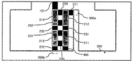
- FIG. 3 is an enlarged perspective view of a broadband circuit according to an embodiment of the present invention.
- FIG. 4 is an equivalent circuit diagram of a broadband circuit according to an embodiment of the present invention.
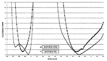
- FIG. 5 is a graph comparing voltage standing wave ratio (VSWR) with and without a broadband circuit according to an embodiment of the present invention.
- FIG. 2 is a perspective view illustrating a state in which a broadband circuit is coupled to an antenna according to an exemplary embodiment of the present invention.
- the antenna 100 shown in FIG. 2 includes a carrier 110 and a radiator 120. Since it is an inverted F type antenna, a feed end 121 and a ground end 122 are formed in a part of the radiator 120.
- the feed end 121 is connected to the broadband circuit 200 according to an embodiment of the present invention, the ground end 122 is connected to the ground plane of the communication device.
- an inverted F type antenna is applied, but this is merely exemplary, and an inverted L type antenna or various other antennas may be applied.
- the antenna to be applied to the present invention is preferably a monopole antenna or an antenna in which the monopole is modified rather than the dipole antenna.
- the broadband circuit of the present invention does not operate as a balun, but serves to mediate an unbalanced signal.
- the antenna to be applied to the present invention is preferably a small antenna having a size of ⁇ / 4 or less. In the case of a large antenna, even if the wideband circuit according to the present invention is not necessarily applied, there are various methods for implementing wideband and high gain.
- the antenna 100 originally operates in the first service band. That is, when the antenna 100 operates alone without a broadband circuit according to an embodiment of the present invention, the available service band may be referred to as a first service band.
- the first service band does not simply mean one service band but may include one or more service bands.
- One object of the present invention is to enable the antenna 100 to operate in a second service band wider than the first service band. This object is achieved by the broadband circuit 200 according to an embodiment of the present invention interposed between the power supply unit 400 and the antenna 100 of the communication device.
- the broadband circuit 200 may be provided as a separate component, but eventually aims to be applied to a communication device. Accordingly, according to another embodiment of the present invention, a communication device including the broadband circuit 200 to be described below is provided. That is, since the broadband circuit 200 of the present invention is a circuit used in a communication device requiring the antenna 100, the broadband circuit 200 may be applied to various communication devices such as a mobile communication terminal, a smart phone, a notebook computer, and the like.
- FIG. 3 shows a broadband circuit according to an embodiment of the present invention in detail.
- 4 shows an equivalent circuit diagram of a broadband circuit according to an embodiment of the present invention.
- 4 (a) shows only an equivalent circuit diagram, and
- FIG. 4 (b) adds reference numerals to correspond to FIG. 3.
- the broadband circuit includes a first line 211, a second line 212, a third line 213, a fourth line 214, and a first line.
- the capacitor 231 includes a second capacitor 232, a third capacitor 233, a fourth capacitor 234, a first inductor 251, and a second inductor 252.
- One end of the first line 211 is connected to the power supply unit 400, and the other end 211b is connected to the first capacitor 231.
- one end 212a is connected to a portion 300a of the ground plane, and the other end 212b is connected to the first capacitor 231. That is, the first capacitor 231 may be interposed between the other end 211b of the first line 211 and the other end 212b of the second line.
- one end 213a is connected to the other part 300b of the ground plane, and the other end 213b is connected to the second capacitor 232.
- the fourth line 214 has one end 214a connected to the feed end 121 extending from the antenna 100, and the other end 214b is connected to the second capacitor 232. That is, the second capacitor 232 may be interposed between the other end 213b of the third line 213 and the other end 214b of the fourth line.
- the first track 211 and the third track 213 are parallel to each other, and the second track 212 and the fourth track 214 are also parallel to each other.
- side by side does not mean that they are physically completely parallel. It will be appreciated that each track extends apart from each other.
- a third capacitor 233 and a first inductor 251 are interposed between the first line 211 and the third line 213.
- the first inductor 251 is disposed closer to the other ends 211b and 213b of the first and third lines than the third capacitor 233.
- a fourth capacitor 234 and a second inductor 252 are interposed between the second line 212 and the fourth line 214.
- the second inductor 252 is disposed closer to the other ends 212b and 214b of the second and fourth lines than the fourth capacitor 234.
- the first tuning element 271 may be included between one end 212a of the second line 212 and a part 300a of the ground plane.
- the second tuning element 272 may be further included between the one end 213a of the third line 213 and the other part 300b of the ground plane.
- An inductor may be used as the first and second tuning elements 271 and 272, and the frequency band may be finely adjusted by adjusting the inductance value of the inductor.
- a capacitor may be used instead of an inductor.
- the first to fourth lines 211, 212, 213, and 214 may be formed on a printed circuit board (PCB). That is, the conductive lines formed on the printed circuit board may be used as the first to fourth lines.
- the first to fourth capacitors 231, 232, 233, and 234 and the first and second inductors 251 and 252 may be configured in the form of elements attached to the printed circuit board. For example, a chip type device or the like can be used.
- the first to fourth lines 211, 212, 213, and 214 may be formed on the flexible printed circuit board FPCB, and the first to fourth capacitors 231, 232, 233, 234, and The second inductors 251 and 252 may be configured in the form of elements attached to the flexible printed circuit board.
- the broadband circuit according to the present invention is formed separately from the main circuit board of the communication device, fabrication can be facilitated by using a flexible printed circuit board rather than a general printed circuit board.
- FIG. 5 is a graph comparing the voltage standing wave ratio VSWR with and without the broadband circuit according to an embodiment of the present invention. According to FIG. 5, it can be seen that the bandwidth is broadened in the case where the broadband circuit is applied as compared to the case where only the antenna is applied without the broadband circuit. In particular, it can be seen that even in the LTE 13 band (746 ⁇ 787 MHz) VSWR falls below three.
- FIG. 6 is a graph comparing gains when the broadband circuit according to an embodiment of the present invention is applied and when it is not. According to FIG. 6, it can be seen that the bandwidth is broadly applied to the case where the broadband circuit is applied as compared to the antenna only without the broadband circuit. In some intervals, the gain decreases, but this is not critical to performance. Rather, the gains are noticeably improved in the LTE 13 band (746-787 MHz).
- FIGS. 5 and 6 indicate that even a service band that was not operated when only the antenna 100 is used alone becomes an operable service band by applying the broadband circuit according to an embodiment of the present invention. Able to know.
- the LTE 13 band is not included in the first service band and the LTE 13 band is included in the second service band.
- this description does not specify the first service band and the second service band. It is a matter of course that the above description is merely exemplary and applicable to other service bands.
- the impedance of the antenna feed line has 50 ⁇ . Therefore, how wide a match can be made between the impedance of the antenna represented by the load impedance and the impedance of the feed line represented by the input impedance is a very important factor in the antenna performance. If the impedance converter is derived between the antenna and the feed line, the matching characteristics are induced, and the signal is excited through the magnetic coupling of the impedance converter, so that the signal is excited in a wide band such as the impedance of the antenna rather than the impedance of a specific frequency of the feed line. Impedance matching allows bandwidth to be expanded.
- an impedance converter is used as a basic model, but this is realized by using only a capacitor and an inductor to achieve broadband. That is, the broadband circuit can be configured by combining a passive element to implement a predetermined circuit.
Landscapes
- Engineering & Computer Science (AREA)
- Physics & Mathematics (AREA)
- Acoustics & Sound (AREA)
- Signal Processing (AREA)
- Power Engineering (AREA)
- Health & Medical Sciences (AREA)
- Otolaryngology (AREA)
- Support Of Aerials (AREA)
- Details Of Aerials (AREA)
- Transceivers (AREA)
Abstract
Description
Claims (6)
- 제1 서비스 대역에서 동작하는 안테나와 그 급전부 사이에 개재되어, 상기 안테나가 상기 제1 서비스 대역보다 넓은 제2 서비스 대역에서 동작하도록 하는 광대역 회로로서,A broadband circuit interposed between an antenna operating in a first service band and a feeding part thereof to allow the antenna to operate in a second service band wider than the first service band.일단이 상기 급전부와 연결되는 제1 선로;A first line having one end connected to the feeding part;일단이 접지면의 일부와 연결되는 제2 선로;A second line, one end of which is connected to a part of the ground plane;상기 제1 선로의 타단과 상기 제2 선로의 타단 사이에 개재되는 제1 커패시터;A first capacitor interposed between the other end of the first line and the other end of the second line;일단이 상기 접지면의 다른 일부와 연결되고 상기 제1 선로와 나란한 제3 선로;A third line having one end connected to another part of the ground plane and parallel to the first line;일단이 상기 안테나와 연결되고 상기 제2 선로와 나란한 제4 선로;A fourth line having one end connected to the antenna and parallel to the second line;상기 제3 선로의 타단과 상기 제4 선로의 타단 사이에 개재되는 제2 커패시터;A second capacitor interposed between the other end of the third line and the other end of the fourth line;상기 제1 선로와 상기 제3 선로 사이에 개재되는 제3 커패시터;A third capacitor interposed between the first line and the third line;상기 제1 선로와 상기 제3 선로 사이에 개재되되 상기 제3 커패시터에 비해 상기 제1, 제3 선로의 타단에 가깝게 개재되는 제1 인덕터;A first inductor interposed between the first line and the third line, the first inductor being disposed closer to the other end of the first and third lines than the third capacitor;상기 제2 선로와 상기 제4 선로 사이에 개재되는 제4 커패시터; 및A fourth capacitor interposed between the second line and the fourth line; And상기 제2 선로와 상기 제4 선로 사이에 개재되되 상기 제4 커패시터에 비해 상기 제2, 제4 선로의 타단에 가깝게 개재되는 제2 인덕터A second inductor interposed between the second line and the fourth line, but disposed closer to the other end of the second and fourth lines than the fourth capacitor.를 포함하는 광대역 회로.Broadband circuit comprising a.
- 제1항에 있어서, The method of claim 1,상기 제2 선로의 일단과 상기 접지면의 일부 사이에 제1 튜닝소자가 더 포함되는 광대역 회로.And a first tuning element between one end of the second line and a portion of the ground plane.
- 제1항에 있어서,The method of claim 1,상기 제3 선로의 일단과 상기 접지면의 다른 일부 사이에 제2 튜닝소자가 더 포함되는 광대역 회로.And a second tuning element between one end of the third line and the other part of the ground plane.
- 제1항에 있어서,The method of claim 1,상기 제1 내지 제4 선로는 인쇄회로기판(PCB)에 형성되고,The first to fourth lines are formed on a printed circuit board (PCB),상기 제1 내지 제4 커패시터 및 상기 제1, 제2 인덕터는 상기 인쇄회로기판에 부착되는 소자인 것을 특징으로 하는 광대역 회로.And the first to fourth capacitors and the first and second inductors are elements attached to the printed circuit board.
- 제1항에 있어서,The method of claim 1,상기 제1 내지 제4 선로는 연성인쇄회로기판(FPCB)에 형성되고,The first to fourth lines are formed on the flexible printed circuit board (FPCB),상기 제1 내지 제4 커패시터 및 상기 제1, 제2 인덕터는 상기 연성인쇄회로기판에 부착되는 소자인 것을 특징으로 하는 광대역 회로.And the first to fourth capacitors and the first and second inductors are elements attached to the flexible printed circuit board.
- 제1항 내지 제5항 중 어느 한 항에 따른 광대역 회로를 포함하는 통신 장치.Communication device comprising a wideband circuit as claimed in claim 1.
Priority Applications (5)
| Application Number | Priority Date | Filing Date | Title |
|---|---|---|---|
| BR112014004036A BR112014004036A2 (en) | 2012-01-09 | 2012-12-18 | broadband circuit and communications apparatus including the same |
| US14/009,514 US9203370B2 (en) | 2012-01-09 | 2012-12-18 | Broadband circuit and communication apparatus including same |
| JP2014551180A JP2015507878A (en) | 2012-01-09 | 2012-12-18 | Broadband circuit and communication apparatus including the same |
| EP12865071.0A EP2804258A4 (en) | 2012-01-09 | 2012-12-18 | Broadband circuit and communication apparatus including same |
| CN201280013051.7A CN103430381B (en) | 2012-01-09 | 2012-12-18 | Broadband circuit and communication apparatus including same |
Applications Claiming Priority (2)
| Application Number | Priority Date | Filing Date | Title |
|---|---|---|---|
| KR10-2012-0002276 | 2012-01-09 | ||
| KR1020120002276A KR101271511B1 (en) | 2012-01-09 | 2012-01-09 | Wide band circuit and communication device including the same |
Publications (1)
| Publication Number | Publication Date |
|---|---|
| WO2013105744A1 true WO2013105744A1 (en) | 2013-07-18 |
Family
ID=48781656
Family Applications (1)
| Application Number | Title | Priority Date | Filing Date |
|---|---|---|---|
| PCT/KR2012/011037 WO2013105744A1 (en) | 2012-01-09 | 2012-12-18 | Broadband circuit and communication apparatus including same |
Country Status (7)
| Country | Link |
|---|---|
| US (1) | US9203370B2 (en) |
| EP (1) | EP2804258A4 (en) |
| JP (1) | JP2015507878A (en) |
| KR (1) | KR101271511B1 (en) |
| CN (1) | CN103430381B (en) |
| BR (1) | BR112014004036A2 (en) |
| WO (1) | WO2013105744A1 (en) |
Families Citing this family (3)
| Publication number | Priority date | Publication date | Assignee | Title |
|---|---|---|---|---|
| US9666939B2 (en) * | 2015-02-17 | 2017-05-30 | Joinset Co., Ltd. | Antenna bandwidth expander |
| KR101672035B1 (en) * | 2015-02-17 | 2016-11-03 | 조인셋 주식회사 | Antenna Bandwidth Expander |
| TWI646731B (en) * | 2017-09-04 | 2019-01-01 | 宏碁股份有限公司 | Mobile electronic device |
Citations (4)
| Publication number | Priority date | Publication date | Assignee | Title |
|---|---|---|---|---|
| JP2005198167A (en) * | 2004-01-09 | 2005-07-21 | Toyota Central Res & Dev Lab Inc | Balanced line-unbalanced line connector |
| JP2005311579A (en) * | 2004-04-20 | 2005-11-04 | Miyoshi Electronics Corp | Semiconductor device |
| KR20080040354A (en) * | 2006-11-03 | 2008-05-08 | (주)내일커뮤니티 | Wideband blocking filter |
| KR20080086709A (en) * | 2007-03-23 | 2008-09-26 | 캠아이티(주) | Burial electromagnetic interference filter |
Family Cites Families (10)
| Publication number | Priority date | Publication date | Assignee | Title |
|---|---|---|---|---|
| US4761623A (en) * | 1986-12-04 | 1988-08-02 | Corcom Inc. | Broadband RFI power line filter |
| US6121940A (en) * | 1997-09-04 | 2000-09-19 | Ail Systems, Inc. | Apparatus and method for broadband matching of electrically small antennas |
| CN1778014B (en) * | 2003-06-04 | 2011-06-15 | 株式会社村田制作所 | Frequency-variable antenna and communication device having the same |
| DE602005002547T2 (en) * | 2004-02-23 | 2008-06-12 | Georgia Tech Research Corp. | PASSIVE SIGNAL PROCESSING COMPONENTS ON LIQUID CRYSTAL POLYMER AND MULTILAYER POLYMER BASIS FOR HF / WIRELESS MULTI-BAND APPLICATIONS |
| US8067997B2 (en) * | 2005-11-10 | 2011-11-29 | The Arizona Board Of Regents On Behalf Of The University Of Arizona | Apparatus and method of selecting components for a reconfigurable impedance match circuit |
| CN101359918B (en) * | 2007-08-02 | 2012-05-30 | 合邦电子股份有限公司 | Digital frequency-modulation stereo emitter and digital frequency-modulation duplex circuit |
| JP4910967B2 (en) * | 2007-10-03 | 2012-04-04 | ソニー株式会社 | Antenna substrate for non-contact communication device and non-contact communication device |
| CN101577485B (en) * | 2008-05-08 | 2012-03-14 | 鸿富锦精密工业(深圳)有限公司 | Wide band filter |
| CN102326296A (en) * | 2009-02-19 | 2012-01-18 | 盖尔创尼克斯有限公司 | Compact multi-band antennas |
| WO2011090048A1 (en) * | 2010-01-19 | 2011-07-28 | 株式会社村田製作所 | Frequency stabilization circuit, frequency stabilization device, antenna device, communication terminal apparatus, and impedance transformation element |
-
2012
- 2012-01-09 KR KR1020120002276A patent/KR101271511B1/en active IP Right Grant
- 2012-12-18 US US14/009,514 patent/US9203370B2/en not_active Expired - Fee Related
- 2012-12-18 JP JP2014551180A patent/JP2015507878A/en active Pending
- 2012-12-18 EP EP12865071.0A patent/EP2804258A4/en not_active Withdrawn
- 2012-12-18 BR BR112014004036A patent/BR112014004036A2/en not_active IP Right Cessation
- 2012-12-18 CN CN201280013051.7A patent/CN103430381B/en not_active Expired - Fee Related
- 2012-12-18 WO PCT/KR2012/011037 patent/WO2013105744A1/en active Application Filing
Patent Citations (4)
| Publication number | Priority date | Publication date | Assignee | Title |
|---|---|---|---|---|
| JP2005198167A (en) * | 2004-01-09 | 2005-07-21 | Toyota Central Res & Dev Lab Inc | Balanced line-unbalanced line connector |
| JP2005311579A (en) * | 2004-04-20 | 2005-11-04 | Miyoshi Electronics Corp | Semiconductor device |
| KR20080040354A (en) * | 2006-11-03 | 2008-05-08 | (주)내일커뮤니티 | Wideband blocking filter |
| KR20080086709A (en) * | 2007-03-23 | 2008-09-26 | 캠아이티(주) | Burial electromagnetic interference filter |
Non-Patent Citations (1)
| Title |
|---|
| See also references of EP2804258A4 * |
Also Published As
| Publication number | Publication date |
|---|---|
| BR112014004036A2 (en) | 2017-03-07 |
| US9203370B2 (en) | 2015-12-01 |
| CN103430381B (en) | 2015-05-20 |
| CN103430381A (en) | 2013-12-04 |
| JP2015507878A (en) | 2015-03-12 |
| US20140327498A1 (en) | 2014-11-06 |
| KR101271511B1 (en) | 2013-06-05 |
| EP2804258A4 (en) | 2015-09-02 |
| EP2804258A1 (en) | 2014-11-19 |
Similar Documents
| Publication | Publication Date | Title |
|---|---|---|
| CN102077416B (en) | An antenna arrangement | |
| US20110210898A1 (en) | Ground radiation antenna | |
| US8648763B2 (en) | Ground radiator using capacitor | |
| CN104466361B (en) | A kind of mobile phone and its antenna | |
| WO2013182114A1 (en) | Wireless device and method for reducing aerial mutual interference therein | |
| WO2013105744A1 (en) | Broadband circuit and communication apparatus including same | |
| CN103022648A (en) | Low-profile mobile terminal antenna | |
| CN105428789A (en) | Antenna and electronic terminal including the antenna | |
| CN107112633B (en) | Mobile terminal | |
| CN106100652A (en) | Mixed-dispel suppression device and method | |
| US9570800B2 (en) | Ground antenna and ground radiator using capacitor | |
| WO2010110517A9 (en) | Antenna using a reactive element | |
| CN205082056U (en) | HF link and one -piece type daughter board of ordinary circuit | |
| US8054238B2 (en) | Balanced PIFA and method for manufacturing the same | |
| CN106848542A (en) | A kind of antenna and mobile terminal | |
| CN103050791A (en) | Circuit with multi-antenna compatibility | |
| CN207217790U (en) | Multi-Function Antenna device and mobile terminal | |
| CN206272580U (en) | Directive overrurrent relay coupler and RF front-end module | |
| CN102013566A (en) | PCB (printed circuit board) Bluetooth antenna and mobile phone | |
| CN106711612A (en) | Antenna dual-working-frequency switching circuit and electronic apparatus | |
| WO2015152685A1 (en) | Broadband matching module and communication device including same | |
| CN201266674Y (en) | Antenna of terminal equipment | |
| WO2015152687A1 (en) | Broadband module and communication device including same | |
| WO2015152686A1 (en) | Broadband module and communication device including same | |
| CN202231714U (en) | Matching design circuit for RF patch antenna |
Legal Events
| Date | Code | Title | Description |
|---|---|---|---|
| 121 | Ep: the epo has been informed by wipo that ep was designated in this application |
Ref document number: 12865071 Country of ref document: EP Kind code of ref document: A1 |
|
| REEP | Request for entry into the european phase |
Ref document number: 2012865071 Country of ref document: EP |
|
| WWE | Wipo information: entry into national phase |
Ref document number: 2012865071 Country of ref document: EP |
|
| WWE | Wipo information: entry into national phase |
Ref document number: 14009514 Country of ref document: US |
|
| ENP | Entry into the national phase |
Ref document number: 2014551180 Country of ref document: JP Kind code of ref document: A |
|
| NENP | Non-entry into the national phase |
Ref country code: DE |
|
| REG | Reference to national code |
Ref country code: BR Ref legal event code: B01A Ref document number: 112014004036 Country of ref document: BR |
|
| ENP | Entry into the national phase |
Ref document number: 112014004036 Country of ref document: BR Kind code of ref document: A2 Effective date: 20140220 |