WO2013100666A1 - 이중여자 유도형 풍력발전 시스템의 전류리플 저감장치 및 그 방법 - Google Patents
이중여자 유도형 풍력발전 시스템의 전류리플 저감장치 및 그 방법 Download PDFInfo
- Publication number
- WO2013100666A1 WO2013100666A1 PCT/KR2012/011638 KR2012011638W WO2013100666A1 WO 2013100666 A1 WO2013100666 A1 WO 2013100666A1 KR 2012011638 W KR2012011638 W KR 2012011638W WO 2013100666 A1 WO2013100666 A1 WO 2013100666A1
- Authority
- WO
- WIPO (PCT)
- Prior art keywords
- current
- ripple
- rotor
- generator
- value
- Prior art date
- Legal status (The legal status is an assumption and is not a legal conclusion. Google has not performed a legal analysis and makes no representation as to the accuracy of the status listed.)
- Ceased
Links
Images

Classifications
-
- H—ELECTRICITY
- H02—GENERATION; CONVERSION OR DISTRIBUTION OF ELECTRIC POWER
- H02M—APPARATUS FOR CONVERSION BETWEEN AC AND AC, BETWEEN AC AND DC, OR BETWEEN DC AND DC, AND FOR USE WITH MAINS OR SIMILAR POWER SUPPLY SYSTEMS; CONVERSION OF DC OR AC INPUT POWER INTO SURGE OUTPUT POWER; CONTROL OR REGULATION THEREOF
- H02M1/00—Details of apparatus for conversion
- H02M1/14—Arrangements for reducing ripples from DC input or output
-
- H—ELECTRICITY
- H02—GENERATION; CONVERSION OR DISTRIBUTION OF ELECTRIC POWER
- H02P—CONTROL OR REGULATION OF ELECTRIC MOTORS, ELECTRIC GENERATORS OR DYNAMO-ELECTRIC CONVERTERS; CONTROLLING TRANSFORMERS, REACTORS OR CHOKE COILS
- H02P9/00—Arrangements for controlling electric generators for the purpose of obtaining a desired output
- H02P9/007—Control circuits for doubly fed generators
-
- H—ELECTRICITY
- H02—GENERATION; CONVERSION OR DISTRIBUTION OF ELECTRIC POWER
- H02P—CONTROL OR REGULATION OF ELECTRIC MOTORS, ELECTRIC GENERATORS OR DYNAMO-ELECTRIC CONVERTERS; CONTROLLING TRANSFORMERS, REACTORS OR CHOKE COILS
- H02P9/00—Arrangements for controlling electric generators for the purpose of obtaining a desired output
- H02P9/08—Control of generator circuit during starting or stopping of driving means, e.g. for initiating excitation
-
- F—MECHANICAL ENGINEERING; LIGHTING; HEATING; WEAPONS; BLASTING
- F03—MACHINES OR ENGINES FOR LIQUIDS; WIND, SPRING, OR WEIGHT MOTORS; PRODUCING MECHANICAL POWER OR A REACTIVE PROPULSIVE THRUST, NOT OTHERWISE PROVIDED FOR
- F03D—WIND MOTORS
- F03D7/00—Controlling wind motors
- F03D7/02—Controlling wind motors the wind motors having rotation axis substantially parallel to the air flow entering the rotor
- F03D7/04—Automatic control; Regulation
-
- F—MECHANICAL ENGINEERING; LIGHTING; HEATING; WEAPONS; BLASTING
- F03—MACHINES OR ENGINES FOR LIQUIDS; WIND, SPRING, OR WEIGHT MOTORS; PRODUCING MECHANICAL POWER OR A REACTIVE PROPULSIVE THRUST, NOT OTHERWISE PROVIDED FOR
- F03D—WIND MOTORS
- F03D9/00—Adaptations of wind motors for special use; Combinations of wind motors with apparatus driven thereby; Wind motors specially adapted for installation in particular locations
- F03D9/20—Wind motors characterised by the driven apparatus
- F03D9/25—Wind motors characterised by the driven apparatus the apparatus being an electrical generator
-
- Y—GENERAL TAGGING OF NEW TECHNOLOGICAL DEVELOPMENTS; GENERAL TAGGING OF CROSS-SECTIONAL TECHNOLOGIES SPANNING OVER SEVERAL SECTIONS OF THE IPC; TECHNICAL SUBJECTS COVERED BY FORMER USPC CROSS-REFERENCE ART COLLECTIONS [XRACs] AND DIGESTS
- Y02—TECHNOLOGIES OR APPLICATIONS FOR MITIGATION OR ADAPTATION AGAINST CLIMATE CHANGE
- Y02E—REDUCTION OF GREENHOUSE GAS [GHG] EMISSIONS, RELATED TO ENERGY GENERATION, TRANSMISSION OR DISTRIBUTION
- Y02E10/00—Energy generation through renewable energy sources
- Y02E10/70—Wind energy
- Y02E10/72—Wind turbines with rotation axis in wind direction
-
- Y—GENERAL TAGGING OF NEW TECHNOLOGICAL DEVELOPMENTS; GENERAL TAGGING OF CROSS-SECTIONAL TECHNOLOGIES SPANNING OVER SEVERAL SECTIONS OF THE IPC; TECHNICAL SUBJECTS COVERED BY FORMER USPC CROSS-REFERENCE ART COLLECTIONS [XRACs] AND DIGESTS
- Y02—TECHNOLOGIES OR APPLICATIONS FOR MITIGATION OR ADAPTATION AGAINST CLIMATE CHANGE
- Y02E—REDUCTION OF GREENHOUSE GAS [GHG] EMISSIONS, RELATED TO ENERGY GENERATION, TRANSMISSION OR DISTRIBUTION
- Y02E10/00—Energy generation through renewable energy sources
- Y02E10/70—Wind energy
- Y02E10/76—Power conversion electric or electronic aspects
Definitions
- the present invention relates to a current ripple reduction device and a method of a double-excitation induction wind power generation system, and more particularly, to reduce the ripple generated in the rotor current generated when the system voltage drops, PCS (Power Converter) in the system
- PCS Power Converter
- the present invention relates to a current ripple reduction device and a method for improving the control performance of the system.
- the stator of the generator is directly connected to the system, and the rotor of the generator is a PCS (Power Converter System) and It is connected, characterized in that for controlling the active power and reactive power supplied to the grid power through the rotor side converter connected to the rotor.
- PCS Power Converter System
- An object of the present invention is to provide a current ripple reduction apparatus and method for reducing the current ripple generation of the rotor in the double-excited induction wind power generator generated when the voltage of the grid power supply.
- the rotor current of the generator is separated into a ripple current which is a current component having the same frequency as the frequency of the normal current and the grid power of the coordinate transformation based on the slip angle, and the separated A ripple current detector for extracting a ripple current and transmitting the ripple current to the ripple current controller 300; And generating and adding a compensation voltage value based on the ripple current received from the ripple current sensing unit to a reference rotor voltage value input to the rotor side converter of the generator to reduce current ripple generated in the rotor current of the generator.
- a ripple current controller includes.
- the ripple current detection unit the coordinate converter for receiving the rotor current of the generator and outputs a coordinate conversion value based on the slip angle;
- a band pass filter configured to receive an output of the coordinate converter and output only a value having a frequency band equal to that of the system power; And output a ripple current by transforming the value output from the band pass filter based on the phase angle of a system power supply, and subtracting the value output from the band pass filter from the value output from the coordinate converter to a normal current.
- Ripple current extractor for outputting; It is preferable to include.
- the ripple current controller outputs a compensation voltage value for causing the ripple current to follow the reference ripple current based on the ripple current output from the ripple current sensing unit and a reference ripple current input from the outside.
- Current controller And a current ripple receiving the compensation voltage value based on the rotor phase angle of the generator and converting the coordinates, and adding the result value to a reference rotor voltage value input to a voltage modulator connected to the rotor side converter of the generator. Controller; It is preferable to include.
- the current ripple reduction method using the current ripple reduction device includes.
- the first step may include a step 1-1 of receiving a rotor current of the generator and outputting a coordinate conversion value based on the slip angle; A first and second step of band-passing and outputting only a value having a frequency band equal to the frequency of the system power among the values output in the first-first step; And a first to third step of converting the value output in the first and second steps based on the phase angle of the grid power supply and outputting the ripple current. It is preferable to include.
- the current ripple generated in the rotor current when the grid voltage drops is reduced, thereby improving the quality of power supplied to the grid power.
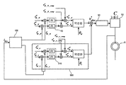
- FIG. 1 is a view for explaining the configuration of the current ripple reduction device of the dual excitation induction wind power generation system according to the present invention.
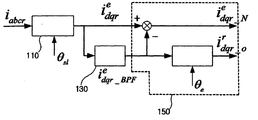
- FIG. 2 is a view for explaining the configuration of the ripple current sensing unit in the current ripple reduction device of the dual excitation induction wind power generation system according to the present invention.
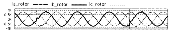
- 3A and 3B are diagrams comparing current ripples generated in the rotor current when the current ripple reduction device according to the present invention is applied and when it is not applied.
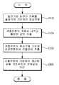
- FIG. 4 is a view for explaining the flow of the current ripple reduction method of the dual excitation induction wind power generation system according to the present invention.
- the PCS Power Converting system
- the control including the current ripple reduction device, other first current controller and the voltage modulator according to the present invention module
- a rotor side converter and a grid side converter for determining an output of the wind power generation system according to the control of the control module
- a direct current capacitor connecting the rotor side converter and the grid side converter.
- an LCL filter which connects the grid-side converter and the grid power supply and blocks harmonic inflow into the grid power supply. It includes.
- FIG. 1 is a view for explaining the configuration of the current ripple reduction device of the dual excitation induction-type wind power generation system according to the present invention
- Figure 2 is a ripple current in the current ripple reduction device of the dual excitation induction-type wind power generation system according to the present invention It is a figure for demonstrating the structure of a detection part.
- the current ripple reduction device is a frequency equal to the frequency of the normal current and the grid voltage of the value of the coordinate conversion of the rotor current of the dual excitation induction generator (G; hereinafter, 'generator') based on the slip angle.
- a ripple current detector 100 for separating into a ripple current which is a current component to have and extracting the separated ripple current and transmitting the ripple current to the ripple current controller 300; And a current ripple generated in the rotor current of the generator by generating and adding a compensation voltage value based on the ripple current received from the ripple current sensing unit 100 to a reference rotor voltage value input to the rotor side converter of the generator.
- Ripple current control unit 300 to reduce the; It includes.
- the ripple current detector 100 includes: a coordinate converter 110 for receiving a rotor current of the generator and outputting a coordinate converted value based on the slip angle; A band pass filter 130 which receives the output of the coordinate converter 110 and outputs only a value having a frequency band equal to the frequency of the grid voltage; And outputting the value output from the band pass filter 130 as a ripple current by coordinate conversion based on a phase angle of a system power source, and outputting the ripple current from the value output from the coordinate converter 110.
- a ripple current extractor 150 subtracting the set value to output a normal current; It includes.
- the ripple current detector 100 When the rotor current i abc flowing in the rotor of the generator G is input to the ripple current detector 100, The ripple current detector 100 outputs a coordinate value i e dqr of the rotor current through the coordinate converter 110 based on a slip angle ⁇ sl .
- the slip angle ⁇ sl is calculated by subtracting the rotation angle ⁇ r of the rotor from the phase angle ⁇ e of the system power supply.
- the current extractor 150 outputs a coordinate converted value based on the phase angle of the grid power supply value (i e dqr_BPF ) output from the band pass filter 130 as a ripple current i r dqr_o . from the value (i e dqr) output from the converter 110 and outputs the steady-state current (i e dqr_n) by subtracting the value (e i dqr_BPF) output from the band-pass filter 130.
- the normal current (i e dqr_n ) among the values output from the ripple current extractor 150 is input to the first current controller 10, and the ripple current (among the values output from the ripple current extractor 150).
- i r dqr_o is input to the ripple current controller 300.
- the ripple current (i r dqr_o) is separated into a current component (i r dr_o) and current components (i r qr_o) based on the q-axis based on the d-axis is input to the ripple current control unit 300, the normal current (i e dqr_n) are also separated by a current component (i e qr_o) based on the current component (i dr_o e) and the q-axis based on the d-axis input to the first current controller 10.
- the first current controller 10 outputs a value based on the steady current i e dqr_n received from the ripple current extractor 150, and the value output from the first current controller 10 is Coordinate transformation is performed based on the slip angle ⁇ sl and is input to the voltage modulator 30 connected to the rotor side converter 50 of the generator as the reference rotor voltage value v * abcr .
- the ripple current controller 300 may calculate a compensation voltage value for causing the ripple current to follow the reference ripple current based on the ripple current output from the ripple current sensing unit 100 and a reference ripple current input from the outside.
- a second current controller 310 for outputting; And receiving the compensation voltage value and converting the coordinates based on the rotor phase angle of the generator, and the reference rotor voltage input to the voltage modulator 30 connected to the rotor-side converter 50 of the generator.
- a current ripple controller 330 that adds to the value; It includes.
- ripple current control unit 300 of the ripple current sensing unit ripple current (d-axis component of the i r dr_o and q-axis component of from 100, as described above, i r qr_o ) and a reference ripple current (including d r- component i r * dr_o and q-axis component i r * qr_o ) input from the second current controller 310 to receive the ripple current.
- a compensation voltage generating a (d-axis component of v e * dr_o and q-axis component of v e * including qr_o), and said compensating the current ripple and the voltage value controller 330 for so as to follow the reference ripple current
- a reference rotor voltage which is a value calculated by inverting the coordinates by the rotor phase angle ⁇ r of the generator and inverting the output value of the first current controller 10 by the slip angle ⁇ sl .
- the output value of the current ripple controller 330 is added to the value v * abcr .
- the voltage modulator 30 receives an input value of the current ripple controller 330 by adding it to the reference rotor voltage value v * abcr , and modulates the output to the rotor side converter 50. .
- FIG. 4 is a view for explaining the flow of the current ripple reduction method of the dual excitation induction wind power generation system according to the present invention.
- a current ripple reduction method comprises: a first step of separating a rotor current of a generator into a ripple current which is a current component having a frequency equal to a frequency of a normal current and a grid power supply among coordinates converted based on a slip angle; And a second step of adding a compensation voltage value determined based on the ripple current separated in the first step, to a reference rotor voltage value input to a voltage modulator connected to the rotor side converter of the generator. It includes.
- the first step may include a step 1-1 of receiving a rotor current of the generator and outputting a coordinate conversion value based on the slip angle; A first and second step of band-passing and outputting only a value having a frequency band equal to the frequency of the system power among the values output in the first-first step; And a first to third step of converting the value output in the first and second steps based on the phase angle of the grid power supply and outputting the ripple current. It is preferable to include.
- coordinate transformation is performed based on a slip angle of a rotor current of a generator (S110).
- the rotor current of the coordinate-transformed generator is input to the band pass filter 130 to extract only a portion having the same value as the frequency band of the grid power supply (S130).
- the ripple current is extracted by performing coordinate transformation on the value extracted in the step S130 based on the phase angle of the system power supply (S150).
- step S150 the ripple current extracted in step S150 is input to the current controller and the output value is added to the reference rotor voltage value input to the rotor-side converter in the generator (S300).
Landscapes
- Engineering & Computer Science (AREA)
- Power Engineering (AREA)
- Life Sciences & Earth Sciences (AREA)
- Sustainable Development (AREA)
- Sustainable Energy (AREA)
- Chemical & Material Sciences (AREA)
- Combustion & Propulsion (AREA)
- Mechanical Engineering (AREA)
- General Engineering & Computer Science (AREA)
- Control Of Eletrric Generators (AREA)
Description
본 발명은 이중여자 유도형 풍력발전 시스템의 전류리플 저감장치 및 그 방법에 관한 것으로, 보다 상세하게는 계통전압이 강하되는 경우 발생하는 회전자 전류에 발생하는 리플을 저감하여 시스템 내 PCS(Power Converter System)의 제어성능을 향상시키는 전류리플 저감장치 및 그 방법에 관한 것이다.
최근 화석연료의 고갈에 대비하여 새로운 에너지원으로 풍력발전 방식이 각광을 받고 있으며, 상기 풍력발전에 의해 MW급 이상의 출력을 발생하는 시스템의 경우 주로 이중여자 유도형 발전기(Double Fed Induction Generator; 이하, 'DFIG')를 사용하는 방식과 영구자석형 발전기(Permanent Magnetic Generator : 이하,'PMG')를 사용하는 방식이 대표적이다.
이중, 상기 이중여자 유도형 발전기(DFIG)를 사용하는 풍력발전 시스템의 경우, 발전기의 고정자(Stator)가 계통에 직접적으로 연결되어 있고 발전기의 회전자(Roter)의 경우 PCS(Power Converter System)과 연결되어 있으며, 상기 회전자와 연결된 회전자측 컨버터를 통해 계통전원으로 공급되는 유효전력 및 무효전력을 제어하는 것을 특징으로 한다.
이러한 이중여자 유도형 발전기(DFIG)에 있어서 계통전원으로 공급되는 발전력의 품질을 개선하기 위한 종래 기술(한국출원 2008-0021928호)가 출원된 바 있으나, 본 발명은 상기 종래 기술과 달리 계통전압이 강하되는 경우 회전자 전류에 발생하는 전류 리플을 저감하는 장치에 관해 이하와 같이 개시한다.
본 발명의 목적은, 계통전원의 전압강하 시 발생하는 이중여자 유도형 풍력발전기 내 회전자의 전류리플 발생을 저감할 수 있는 전류리플 저감장치 및 그 방법을 제공함에 있다.
본 발명에 따른 전류리플 저감장치는, 발전기의 회전자 전류를 슬립각에 기반해 좌표변환한 값 중 정상전류 및 계통전원의 주파수와 동일한 주파수를 갖는 전류성분인 리플전류로 분리하고, 상기 분리된 리플전류를 추출하여 리플전류 제어부(300)로 송신하는 리플전류 감지부; 및 발전기의 회전자 측 컨버터에 입력되는 기준회전자 전압값에 상기 리플전류 감지부로부터 수신한 리플전류에 기반한 보상전압값을 생성하여 가산함으로써 상기 발전기의 회전자 전류에 발생하는 전류 리플을 저감하는 리플전류 제어부; 를 포함한다.
이때, 상기 리플전류 감지부는, 상기 발전기의 회전자 전류를 입력받아 상기 슬립각에 기반하여 좌표변환한 값을 출력하는 좌표변환기; 상기 좌표변환기의 출력을 입력받아 상기 계통전원의 주파수와 동일한 주파수 대역을 갖는 값만을 출력하는 대역통과필터(Band Pass Filter); 및 상기 대역통과필터에서 출력된 값을 계통전원의 위상각에 기반해 좌표변환하여 리플전류로 출력하며, 상기 좌표변환기에서 출력된 값에서 상기 대역통과필터에서 출력된 값을 감산하여 정상전류로 분리하여 출력하는 리플전류 추출기; 를 포함하는 것이 바람직하다.
이때, 상기 리플전류 제어부는, 상기 리플전류 감지부에서 출력한 리플전류 및 외부에서 입력되는 기준리플전류에 기반해 상기 리플전류가 상기 기준리플전류를 추종하도록 하기 위한 보상전압값을 출력하는 제2 전류제어기; 및상기 보상전압값을 입력받아 발전기의 회전자 위상각에 기반해 좌표변환하고, 그 결과값을 상기 발전기의 회전자 측 컨버터와 연결된 전압변조부에 입력되는 기준회전자 전압값에 가산하는 전류리플 제어기; 을 포함하는 것이 바람직하다.
또한, 본 발명에 따른 전류리플 저감장치를 이용한 전류리플 저감방법은, 발전기의 회전자 전류를 슬립각에 기반해 좌표변환한 값 중 정상전류 및 계통전원의 주파수와 동일한 주파수를 갖는 전류성분인 리플전류로 분리하는 제1 단계; 및 상기 제1 단계에서 분리된 리플전류에 기반하여 결정되는 보상전압값을 발전기의 회전자 측 컨버터와 연결된 전압변조부에 입력되는 기준회전자 전압값에 가산 하는 제2 단계; 를 포함한다.
이때, 상기 제1 단계는, 상기 발전기의 회전자 전류를 입력받아 상기 슬립각에 기반하여 좌표변환한 값을 출력하는 제 1-1단계; 상기 제1-1단계에서 출력된 값 중 상기 계통전원의 주파수와 동일한 주파수 대역을 갖는 값만을 대역통과시켜 출력하는 제 1-2단계; 및 상기 제 1-2단계에서 출력된 값을 계통전원의 위상각에 기반해 좌표변환하여 리플전류로 출력하는 제 1-3단계; 를 포함하는 것이 바람직하다.
본 발명에 따르면, 기존의 이중여자 유도형 풍력발전 시스템에 비해, 계통전압 강하 시 회전자 전류에 발생하는 전류리플이 저감되어 계통전원으로 공급되는 전력의 품질을 향상시키는 효과가 있다.
도 1은 본 발명에 따른 이중여자 유도형 풍력발전 시스템의 전류리플 저감장치의 구성을 설명하기 위한 도면이다.
도 2는 본 발명에 따른 이중여자 유도형 풍력발전 시스템의 전류리플 저감장치 내 리플전류 감지부의 구성을 설명하기 위한 도면이다.
도 3a 및 도 3b는 본 발명에 따른 전류리플 저감장치가 적용된 경우 및 적용되지 않은 경우 회전자 전류에 발생하는 전류리플을 비교한 그림이다.
도 4는 본 발명에 따른 이중여자 유도형 풍력발전 시스템의 전류리플 저감방법의 흐름을 설명하기 위한 도면이다.
본 발명의 실시를 위한 구체적인 내용을 설명하기에 앞서, 본 발명의 기술적 요지와 직접적 관련이 없는 구성에 대해서는 본 발명의 기술적 요지를 흩뜨리지 않는 범위 내에서 생략하였음에 유의하여야 할 것이다. 또한, 본 명세서 및 청구범위에 사용된 용어 또는 단어는 발명자가 자신의 발명을 최선의 방법으로 설명하기 위해 적절한 용어의 개념을 정의할 수 있다는 원칙에 입각하여 본 발명의 기술적 사상에 부합하는 의미와 개념으로 해석되어야 할 것이다.
설명하기에 앞서, 본 발명에 따른 전류리플 저감장치를 포함하는 풍력발전 시스템의 PCS(Power Converting system)은, 본 발명에 따른 전류리플 저감장치, 그 외 제1 전류제어기 및 전압변조부를 포함하는 제어모듈; 상기 제어모듈의 제어에 따라 상기 풍력발전시스템의 출력을 결정하는 회전자측 컨버터와 계통측 컨버터; 및 상기 회전자측 컨버터와 계통측 컨버터를 연계하는 직류단 커패시터; 및 상기 계통측 컨버터와 계통전원을 연결하며 계통전원으로의 고조파 유입을 차단하는 LCL필터; 를 포함하고 있다.
이하, 본 발명에 따른 전류리플 저감장치에 대해 첨부한 예시도면을 토대로 상세히 설명한다. 도 1은 본 발명에 따른 이중여자 유도형 풍력발전 시스템의 전류리플 저감장치의 구성을 설명하기 위한 도면이며, 도 2는 본 발명에 따른 이중여자 유도형 풍력발전 시스템의 전류리플 저감장치 내 리플전류 감지부의 구성을 설명하기 위한 도면이다.
본 발명에 따른 전류리플 저감장치는, 이중여자 유도형 발전기(G; 이하, '발전기')의 회전자 전류를 슬립각에 기반해 좌표변환한 값 중 정상전류 및 계통전압의 주파수와 동일한 주파수를 갖는 전류성분인 리플전류로 분리하고, 상기 분리된 리플전류를 추출하여 리플전류 제어부(300)로 송신하는 리플전류 감지부(100); 및 발전기의 회전자 측 컨버터에 입력되는 기준회전자 전압값에 상기 리플전류 감지부(100)로부터 수신한 리플전류에 기반한 보상전압값을 생성하여 가산함으로써 상기 발전기의 회전자 전류에 발생하는 전류 리플을 저감하는 리플전류 제어부(300); 를 포함한다.
상기 리플전류 감지부(100)는, 상기 발전기의 회전자 전류를 입력받아 상기 슬립각에 기반하여 좌표변환한 값을 출력하는 좌표변환기(110); 상기 좌표변환기(110)의 출력을 입력받아 상기 계통전압의 주파수와 동일한 주파수 대역을 갖는 값만을 출력하는 대역통과필터(Band Pass Filter)(130); 및 상기 대역통과필터(130)에서 출력된 값을 계통전원의 위상각에 기반해 좌표변환하여 리플전류로 출력하며, 상기 좌표변환기(110)에서 출력된 값에서 상기 대역통과필터(130)에서 출력된 값을 감산하여 정상전류로 출력하는 리플전류 추출기(150); 를 포함한다.
도 2를 참조하여 상기 리플전류 감지부(100)의 동작을 보다 상세히 설명하면, 발전기(G)의 회전자에 흐르는 회전자 전류(iabc)가 상기 리플전류 감지부(100)에 입력되면, 상기 리플전류 감지부(100)는 상기 좌표변환기(110)를 통해 슬립각(θsl)에 기반하여 상기 회전자 전류를 좌표변환한 값(ie
dqr)을 출력한다.
이때, 상기 슬립각(θsl)은 계통전원의 위상각(θe)으로부터 회전자의 회전각(θr)을 감산하여 계산된다.
그리고, 상기 좌표변환기(110)에서 출력된 값(ie
dqr)을 상기 대역통과필터(130)를 통해 발전기에 연결된 계통전원의 주파수 대역에 해당되는 값(ie
dqr_BPF)를 출력하며, 상기 리플전류 추출기(150)에서는 상기 대역통과필터(130)에서 출력된 값(ie
dqr_BPF)을 계통전원의 위상각에 기반해 좌표변환한 값을 리플전류(ir
dqr_o)로 출력하며, 또한 상기 좌표변환기(110)에서 출력된 값(ie
dqr)에서 상기 대역통과필터(130)에서 출력된 값(ie
dqr_BPF)을 감산하여 정상전류(ie
dqr_n)로 출력한다.
덧붙여, 상기 리플전류 추출기(150)에서 출력되는 값 중 정상전류(ie
dqr_n)의 경우 상기 제1 전류제어기(10)에 입력되며, 상기 리플전류 추출기(150)에서 출력되는 값 중 리플전류(ir
dqr_o)는 상기 리플전류 제어부(300)로 입력된다.
이때, 상기 리플전류(ir
dqr_o)는 d축에 기반한 전류성분(ir
dr_o) 및 q축에 기반한 전류성분(ir
qr_o)으로 분리되어 상기 리플전류 제어부(300)로 입력되며, 상기 정상전류(ie
dqr_n) 역시 d축에 기반한 전류성분(ie
dr_o) 및 q축에 기반한 전류성분(ie
qr_o)으로 분리되어 상기 제1 전류제어기(10)로 입력된다.
그리고, 상기 제1 전류제어기(10)는 상기 리플전류 추출기(150)로부터 입력받은 상기 정상전류(ie
dqr_n)에 기반하여 값을 출력하고, 상기 제1 전류제어기(10)에서 출력된 값은 슬립각(θsl)에 기반해 좌표변환되어 기준회전자 전압값(v*
abcr)으로 발전기의 회전자 측 컨버터(50)에 연결된 전압변조부(30)에 입력된다.
상기 리플전류 제어부(300)는, 상기 리플전류 감지부(100)에서 출력한 리플전류 및 외부에서 입력되는 기준리플전류에 기반해 상기 리플전류가 상기 기준리플전류를 추종하도록 하기 위한 보상전압값을 출력하는 제2 전류제어기(310); 및 상기 보상전압값을 입력받아 발전기의 회전자 위상각에 기반해 좌표변환하고, 그 결과값을 상기 발전기의 회전자 측 컨버터(50)와 연결된 전압변조부(30)에 입력되는 기준회전자 전압값에 가산하는 전류리플 제어기(330); 을 포함한다.
도 1을 참조하여 상기 리플전류 제어부(300)의 동작을 보다 상세히 설명하면, 전술한 바와 같이 상기 리플전류 감지부(100)로부터 리플전류(d축 성분인 ir
dr_o 및 q축 성분인 ir
qr_o를 포함) 및 외부에서 입력되는 기준리플전류(d축 성분인 ir*
dr_o 및 q축 성분인 ir*
qr_o를 포함)를 상기 제2 전류제어기(310)를 통해 입력받아 상기 리플전류가 상기 기준리플전류를 추종하도록 하기 위한 보상전압값(d축 성분인 ve*
dr_o 및 q축 성분인 ve*
qr_o를 포함)를 생성하고, 상기 보상전압값을 상기 전류리플 제어기(330)에 입력하여 발전기의 회전자 위상각(θr)에 의해 좌표변환한 값을 출력하며, 상기 제1 전류제어기(10)의 출력값을 슬립각(θsl)에 의해 역변환하여 계산되는 값인 기준회전자 전압값(v*
abcr)에 상기 전류리플 제어기(330)의 출력값을 가산한다.
그리고, 상기 전압변조부(30)는 상기 기준회전자 전압값(v*
abcr)에 상기 전류리플 제어기(330)의 출력값을 가산하여 입력받아, 상기 회전자 측 컨버터(50)로 변조하여 출력한다.
이에 따라, 본 발명에 따른 전류리플 저감장치를 포함하는 경우와 그렇지 않은 경우 회전자 전류의 전류리플 발생여부를 시뮬레이션한 결과는 도 3a 및 도 3b에 도시된 바와 같으며, 기존의 풍력발전시스템의 경우 회전자의 각 상별 전류에 전류리플이 상대적으로 큰 폭으로 발생함(도 3a)에 비해, 본 발명에 따른 전류리플 저감장치를 포함하는 풍력발전 시스템의 경우 상대적으로 회전자의 각 상별 전류에 발생하는 전류리플이 저감됨(도 3b)을 알 수 있다.
이하, 본 발명에 따른 전류리플 저감방법에 대해 첨부한 예시도면을 토대로 상세히 설명한다. 도 4는 본 발명에 따른 이중여자 유도형 풍력발전 시스템의 전류리플 저감방법의 흐름을 설명하기 위한 도면이다.
본 발명에 따른 전류리플 저감방법은, 발전기의 회전자 전류를 슬립각에 기반해 좌표변환한 값 중 정상전류 및 계통전원의 주파수와 동일한 주파수를 갖는 전류성분인 리플전류로 분리하는 제1 단계; 및 상기 제1 단계에서 분리된 리플전류에 기반하여 결정되는 보상전압값을 발전기의 회전자 측 컨버터와 연결된 전압변조부에 입력되는 기준회전자 전압값에 가산 하는 제2 단계; 를 포함한다.
이때, 상기 제1 단계는, 상기 발전기의 회전자 전류를 입력받아 상기 슬립각에 기반하여 좌표변환한 값을 출력하는 제 1-1단계; 상기 제1-1단계에서 출력된 값 중 상기 계통전원의 주파수와 동일한 주파수 대역을 갖는 값만을 대역통과시켜 출력하는 제 1-2단계; 및 상기 제 1-2단계에서 출력된 값을 계통전원의 위상각에 기반해 좌표변환하여 리플전류로 출력하는 제 1-3단계; 를 포함하는 것이 바람직하다.
도 4를 참조하여 설명하면, 먼저, 발전기의 회전자 전류를 슬립각에 기반하여 좌표변환을 수행한다(S110).
다음으로, 상기 좌표변환된 발전기의 회전자 전류를 대역통과필터(130)에 입력하여 계통전원의 주파수대역과 동일한 값을 갖는 부분만 추출한다(S130).
다음으로, 상기 S130 단계에서 추출된 값에 대해 계통전원의 위상각에 기반하여 좌표변환을 수행함으로써, 리플전류를 추출한다(S150).
마지막으로, 상기 S150 단계에서 추출된 리플전류를 전류제어기에 입력하여 출력된 값을 발전기 내 회전자측 컨버터에 입력되는 기준회전자 전압값에 가산한다(S300).
이상으로, 본 발명의 기술적 사상을 예시하기 위한 바람직한 실시예와 관련하여 설명하고 도시하였으나, 본 발명은 상기 설명 및 도시대로의 구성 및 작용에만 국한되는 것이 아니다. 아울러 본 발명의 기술적 사상의 범주를 일탈하지 않는 범위 내에서 다수의 변경 및 수정이 가능함을 당업자는 잘 이해할 수 있을 것이다. 따라서 모든 적절한 변경 및 수정이 가해진 발명 및 본 발명의 균등물에 속하는 발명들도 본 발명에 속하는 것으로 간주되어야 할 것이다.
Claims (5)
- 이중여자 유도형 풍력발전 시스템의 전류리플 저감장치에 있어서,발전기의 회전자 전류를 슬립각에 기반해 좌표변환한 값 중 정상전류 및 계통전원의 주파수와 동일한 주파수를 갖는 전류성분인 리플전류로 분리하고, 상기 분리된 리플전류를 추출하여 리플전류 제어부(300)로 송신하는 리플전류 감지부(100); 및발전기의 회전자 측 컨버터에 입력되는 기준회전자 전압값에 상기 리플전류 감지부(100)로부터 수신한 리플전류에 기반한 보상전압값을 생성하여 가산함으로써 상기 발전기의 회전자 전류에 발생하는 전류 리플을 저감하는 리플전류 제어부(300); 를 포함하는 이중여자 유도형 풍력발전 시스템의 전류리플 저감장치.
- 제 1 항에 있어서,상기 리플전류 감지부(100)는,상기 발전기의 회전자 전류를 입력받아 상기 슬립각에 기반하여 좌표변환한 값을 출력하는 좌표변환기(110);상기 좌표변환기(110)의 출력을 입력받아 상기 계통전원의 주파수와 동일한 주파수 대역을 갖는 값만을 출력하는 대역통과필터(Band Pass Filter)(130); 및상기 대역통과필터(130)에서 출력된 값을 계통전원의 위상각에 기반해 좌표변환하여 리플전류로 출력하며, 상기 좌표변환기(110)에서 출력된 값에서 상기 대역통과필터(130)에서 출력된 값을 감산하여 정상전류로 분리하여 출력하는 리플전류 추출기(150); 를 포함하는 것을 특징으로 하는 이중여자 유도형 풍력발전 시스템의 전류리플 저감장치.
- 제 1 항에 있어서,상기 리플전류 제어부(300)는,상기 리플전류 감지부(100)에서 출력한 리플전류 및 외부에서 입력되는 기준리플전류에 기반해 상기 리플전류가 상기 기준리플전류를 추종하도록 하기 위한 보상전압값을 출력하는 제2 전류제어기(310); 및상기 보상전압값을 입력받아 발전기의 회전자 위상각에 기반해 좌표변환하고, 그 결과값을 상기 발전기의 회전자 측 컨버터와 연결된 전압변조부에 입력되는 기준회전자 전압값에 가산하는 전류리플 제어기(330); 을 포함하는 것을 특징으로 하는 이중여자 유도형 풍력발전 시스템의 전류리플 저감장치.
- 전류리플 저감장치를 이용한 이중여자 유도형 풍력발전 시스템의 전류리플 저감방법에 있어서,발전기의 회전자 전류를 슬립각에 기반해 좌표변환한 값 중 정상전류 및 계통전원의 주파수와 동일한 주파수를 갖는 전류성분인 리플전류로 분리하는 제1 단계; 및상기 제1 단계에서 분리된 리플전류에 기반하여 결정되는 보상전압값을 발전기의 회전자 측 컨버터와 연결된 전압변조부에 입력되는 기준회전자 전압값에 가산 하는 제2 단계; 를 포함하는 이중여자 유도형 풍력발전 시스템의 전류리플 저감방법.
- 제 4 항에 있어서,상기 제1 단계는,상기 발전기의 회전자 전류를 입력받아 상기 슬립각에 기반하여 좌표변환한 값을 출력하는 제 1-1단계;상기 제1-1단계에서 출력된 값 중 상기 계통전원의 주파수와 동일한 주파수 대역을 갖는 값만을 대역통과시켜 출력하는 제 1-2단계; 및상기 제 1-2단계에서 출력된 값을 계통전원의 위상각에 기반해 좌표변환하여 리플전류로 출력하는 제 1-3단계; 를 포함하는 것을 특징으로 하는 이중여자 유도형 풍력발전 시스템의 전류리플 저감방법.
Priority Applications (1)
| Application Number | Priority Date | Filing Date | Title |
|---|---|---|---|
| US14/368,851 US20150021914A1 (en) | 2011-12-27 | 2012-12-27 | Apparatus and Method for Reducing Current Ripple in Double Fed Induction Wind Power Generating System |
Applications Claiming Priority (2)
| Application Number | Priority Date | Filing Date | Title |
|---|---|---|---|
| KR10-2011-0143663 | 2011-12-27 | ||
| KR20110143663A KR101288638B1 (ko) | 2011-12-27 | 2011-12-27 | 이중여자 유도형 풍력발전 시스템의 전류리플 저감장치 및 그 방법 |
Publications (1)
| Publication Number | Publication Date |
|---|---|
| WO2013100666A1 true WO2013100666A1 (ko) | 2013-07-04 |
Family
ID=48698008
Family Applications (1)
| Application Number | Title | Priority Date | Filing Date |
|---|---|---|---|
| PCT/KR2012/011638 Ceased WO2013100666A1 (ko) | 2011-12-27 | 2012-12-27 | 이중여자 유도형 풍력발전 시스템의 전류리플 저감장치 및 그 방법 |
Country Status (3)
| Country | Link |
|---|---|
| US (1) | US20150021914A1 (ko) |
| KR (1) | KR101288638B1 (ko) |
| WO (1) | WO2013100666A1 (ko) |
Cited By (2)
| Publication number | Priority date | Publication date | Assignee | Title |
|---|---|---|---|---|
| CN104038030A (zh) * | 2014-06-04 | 2014-09-10 | 华为技术有限公司 | 一种控制母线纹波的方法、装置和系统 |
| CN109424502A (zh) * | 2017-09-04 | 2019-03-05 | 通用电气公司 | 用于防止风力涡轮电力系统的电压骤降的系统及方法 |
Families Citing this family (6)
| Publication number | Priority date | Publication date | Assignee | Title |
|---|---|---|---|---|
| KR101288638B1 (ko) * | 2011-12-27 | 2013-07-22 | 주식회사 효성 | 이중여자 유도형 풍력발전 시스템의 전류리플 저감장치 및 그 방법 |
| EP2922190B1 (en) * | 2012-11-14 | 2020-02-19 | Posco Energy Co. Ltd. | Apparatus for compensating for ripple and offset of inverter, and method therefor |
| KR101564321B1 (ko) | 2014-03-18 | 2015-11-02 | 전자부품연구원 | 발전기의 발전 방법 및 시스템 |
| KR20160148216A (ko) * | 2015-06-16 | 2016-12-26 | 현대자동차주식회사 | 얼터네이터의 리플 제어 장치 및 이를 이용한 리플 제어 방법 |
| TWI641205B (zh) | 2015-09-30 | 2018-11-11 | 財團法人工業技術研究院 | 漣波補償控制方法與應用此漣波補償控制之電能轉換裝置 |
| US10541598B1 (en) | 2018-08-03 | 2020-01-21 | Hamilton Sundstrand Corporation | DC power generating system with voltage ripple compensation |
Citations (5)
| Publication number | Priority date | Publication date | Assignee | Title |
|---|---|---|---|---|
| US20040217596A1 (en) * | 2002-02-11 | 2004-11-04 | Vestas Wind Systems A/S | Variable speed wind turbine having a passive grid side rectifier with scalar power control and dependent pitch control |
| KR20090096849A (ko) * | 2008-03-10 | 2009-09-15 | 엘에스산전 주식회사 | 이중여자 유도형 풍력발전기의 무효전력 제어방법 |
| KR20090096857A (ko) * | 2008-03-10 | 2009-09-15 | 엘에스산전 주식회사 | 이중여자 유도형 풍력발전기에 있어서의 전력 변환 장치 및펄스 폭 변조 제어 방법 |
| KR20110024224A (ko) * | 2009-09-01 | 2011-03-09 | 엘에스산전 주식회사 | 발전기 시스템 및 발전 방법 |
| KR20110075540A (ko) * | 2009-12-28 | 2011-07-06 | 주식회사 효성 | 이중여자 유도형 발전기의 위상오차 보상 장치 및 그 방법 |
Family Cites Families (4)
| Publication number | Priority date | Publication date | Assignee | Title |
|---|---|---|---|---|
| KR101288638B1 (ko) * | 2011-12-27 | 2013-07-22 | 주식회사 효성 | 이중여자 유도형 풍력발전 시스템의 전류리플 저감장치 및 그 방법 |
| JP2014087141A (ja) * | 2012-10-23 | 2014-05-12 | Hitachi Ltd | 回転機およびそのドライブシステム |
| US9537437B2 (en) * | 2013-03-04 | 2017-01-03 | General Electric Company | Method and system for controlling switching frequency of a doubly-fed induction generator (DFIG) |
| US20150173238A1 (en) * | 2013-12-18 | 2015-06-18 | Caterpillar Inc. | Configurable power converter package |
-
2011
- 2011-12-27 KR KR20110143663A patent/KR101288638B1/ko not_active Expired - Fee Related
-
2012
- 2012-12-27 WO PCT/KR2012/011638 patent/WO2013100666A1/ko not_active Ceased
- 2012-12-27 US US14/368,851 patent/US20150021914A1/en not_active Abandoned
Patent Citations (5)
| Publication number | Priority date | Publication date | Assignee | Title |
|---|---|---|---|---|
| US20040217596A1 (en) * | 2002-02-11 | 2004-11-04 | Vestas Wind Systems A/S | Variable speed wind turbine having a passive grid side rectifier with scalar power control and dependent pitch control |
| KR20090096849A (ko) * | 2008-03-10 | 2009-09-15 | 엘에스산전 주식회사 | 이중여자 유도형 풍력발전기의 무효전력 제어방법 |
| KR20090096857A (ko) * | 2008-03-10 | 2009-09-15 | 엘에스산전 주식회사 | 이중여자 유도형 풍력발전기에 있어서의 전력 변환 장치 및펄스 폭 변조 제어 방법 |
| KR20110024224A (ko) * | 2009-09-01 | 2011-03-09 | 엘에스산전 주식회사 | 발전기 시스템 및 발전 방법 |
| KR20110075540A (ko) * | 2009-12-28 | 2011-07-06 | 주식회사 효성 | 이중여자 유도형 발전기의 위상오차 보상 장치 및 그 방법 |
Cited By (4)
| Publication number | Priority date | Publication date | Assignee | Title |
|---|---|---|---|---|
| CN104038030A (zh) * | 2014-06-04 | 2014-09-10 | 华为技术有限公司 | 一种控制母线纹波的方法、装置和系统 |
| CN104038030B (zh) * | 2014-06-04 | 2017-01-04 | 华为技术有限公司 | 一种控制母线纹波的方法、装置和系统 |
| CN109424502A (zh) * | 2017-09-04 | 2019-03-05 | 通用电气公司 | 用于防止风力涡轮电力系统的电压骤降的系统及方法 |
| CN109424502B (zh) * | 2017-09-04 | 2022-05-27 | 通用电气公司 | 用于防止风力涡轮电力系统的电压骤降的系统及方法 |
Also Published As
| Publication number | Publication date |
|---|---|
| US20150021914A1 (en) | 2015-01-22 |
| KR101288638B1 (ko) | 2013-07-22 |
| KR20130075332A (ko) | 2013-07-05 |
Similar Documents
| Publication | Publication Date | Title |
|---|---|---|
| WO2013100666A1 (ko) | 이중여자 유도형 풍력발전 시스템의 전류리플 저감장치 및 그 방법 | |
| US8248039B2 (en) | Control system for an electrical generator and method for controlling an electrical generator | |
| EP2775608B1 (en) | Method and system for controlling switching frequency of a doubly-fed induction generator (DFIG) | |
| CN110277797B (zh) | 基于共直流母线的光伏虚拟同步发电机协调控制方法 | |
| US8502404B2 (en) | Wind power generating system and control method for the same | |
| US10439399B2 (en) | Transformerless power conversion | |
| CN202918232U (zh) | 一种高速无刷直流电动机软起动控制系统 | |
| CN104901322B (zh) | 一种电网电压不对称下变流器的虚拟同步控制系统及方法 | |
| JP2008306829A (ja) | 高調波電流補償装置 | |
| CN104242759B (zh) | 一种基于矢量电力系统稳定器的双馈风力发电系统 | |
| CA3161550C (en) | METHOD AND SYSTEM FOR CONTROLLING THE CONTINUOUS CROSSING OF A HIGH VOLTAGE AND A CONTINUOUS CROSSING OF A LOW VOLTAGE IN A DIRECT-DRIVE PERMANENT MAGNET WIND TURBINE | |
| US9590485B2 (en) | Resonance suppression device | |
| CN109672210B (zh) | 变流器、变流器的高电压穿越控制方法和装置 | |
| CN101702583A (zh) | 一种直驱风力发电变流器的控制方法 | |
| NO20085321L (no) | Framgangsmate for drift av en permanentmagnetisert synkronmaskin samt anordning ved et elektrisk anlegg som omfatter en slik maskin | |
| JP4776597B2 (ja) | 電動機駆動装置および圧縮機駆動装置並びに圧縮機 | |
| CN202111662U (zh) | 一种电机变频调速系统 | |
| Wu et al. | Power conversion interface for small‐capacity wind power generation system | |
| EP3709467A1 (en) | Reduction of subsynchronous active power oscillations in grid forming pwm converters for wind turbine generators | |
| CN102664572A (zh) | 一种中高压无换向器电机的无位置传感器控制装置 | |
| CN102244496A (zh) | 一种电机变频调速系统 | |
| CN102255588B (zh) | 一种变频调速装置 | |
| CN202837385U (zh) | 一种过零检测电路 | |
| US20120043815A1 (en) | Active filtering electrical accumulator unit | |
| CN103728485A (zh) | 具有保护功能的同步电压检测装置 |
Legal Events
| Date | Code | Title | Description |
|---|---|---|---|
| 121 | Ep: the epo has been informed by wipo that ep was designated in this application |
Ref document number: 12862702 Country of ref document: EP Kind code of ref document: A1 |
|
| WWE | Wipo information: entry into national phase |
Ref document number: 14368851 Country of ref document: US |
|
| NENP | Non-entry into the national phase |
Ref country code: DE |
|
| 122 | Ep: pct application non-entry in european phase |
Ref document number: 12862702 Country of ref document: EP Kind code of ref document: A1 |