WO2013100600A1 - 표면품질 및 성형성이 우수한 연료전지 분리판용 스테인리스강 및 그 제조방법 - Google Patents
표면품질 및 성형성이 우수한 연료전지 분리판용 스테인리스강 및 그 제조방법 Download PDFInfo
- Publication number
- WO2013100600A1 WO2013100600A1 PCT/KR2012/011515 KR2012011515W WO2013100600A1 WO 2013100600 A1 WO2013100600 A1 WO 2013100600A1 KR 2012011515 W KR2012011515 W KR 2012011515W WO 2013100600 A1 WO2013100600 A1 WO 2013100600A1
- Authority
- WO
- WIPO (PCT)
- Prior art keywords
- less
- stainless steel
- fuel cell
- formability
- surface quality
- Prior art date
- Legal status (The legal status is an assumption and is not a legal conclusion. Google has not performed a legal analysis and makes no representation as to the accuracy of the status listed.)
- Ceased
Links
Images
Classifications
-
- C—CHEMISTRY; METALLURGY
- C21—METALLURGY OF IRON
- C21D—MODIFYING THE PHYSICAL STRUCTURE OF FERROUS METALS; GENERAL DEVICES FOR HEAT TREATMENT OF FERROUS OR NON-FERROUS METALS OR ALLOYS; MAKING METAL MALLEABLE, e.g. BY DECARBURISATION OR TEMPERING
- C21D8/00—Modifying the physical properties of ferrous metals or ferrous alloys by deformation combined with, or followed by, heat treatment
- C21D8/02—Modifying the physical properties of ferrous metals or ferrous alloys by deformation combined with, or followed by, heat treatment during manufacturing of plates or strips
- C21D8/0247—Modifying the physical properties of ferrous metals or ferrous alloys by deformation combined with, or followed by, heat treatment during manufacturing of plates or strips characterised by the heat treatment
- C21D8/0263—Modifying the physical properties of ferrous metals or ferrous alloys by deformation combined with, or followed by, heat treatment during manufacturing of plates or strips characterised by the heat treatment following hot rolling
-
- C—CHEMISTRY; METALLURGY
- C21—METALLURGY OF IRON
- C21D—MODIFYING THE PHYSICAL STRUCTURE OF FERROUS METALS; GENERAL DEVICES FOR HEAT TREATMENT OF FERROUS OR NON-FERROUS METALS OR ALLOYS; MAKING METAL MALLEABLE, e.g. BY DECARBURISATION OR TEMPERING
- C21D6/00—Heat treatment of ferrous alloys
- C21D6/002—Heat treatment of ferrous alloys containing Cr
-
- C—CHEMISTRY; METALLURGY
- C22—METALLURGY; FERROUS OR NON-FERROUS ALLOYS; TREATMENT OF ALLOYS OR NON-FERROUS METALS
- C22C—ALLOYS
- C22C38/00—Ferrous alloys, e.g. steel alloys
- C22C38/001—Ferrous alloys, e.g. steel alloys containing N
-
- C—CHEMISTRY; METALLURGY
- C22—METALLURGY; FERROUS OR NON-FERROUS ALLOYS; TREATMENT OF ALLOYS OR NON-FERROUS METALS
- C22C—ALLOYS
- C22C38/00—Ferrous alloys, e.g. steel alloys
- C22C38/004—Very low carbon steels, i.e. having a carbon content of less than 0,01%
-
- C—CHEMISTRY; METALLURGY
- C22—METALLURGY; FERROUS OR NON-FERROUS ALLOYS; TREATMENT OF ALLOYS OR NON-FERROUS METALS
- C22C—ALLOYS
- C22C38/00—Ferrous alloys, e.g. steel alloys
- C22C38/02—Ferrous alloys, e.g. steel alloys containing silicon
-
- C—CHEMISTRY; METALLURGY
- C22—METALLURGY; FERROUS OR NON-FERROUS ALLOYS; TREATMENT OF ALLOYS OR NON-FERROUS METALS
- C22C—ALLOYS
- C22C38/00—Ferrous alloys, e.g. steel alloys
- C22C38/04—Ferrous alloys, e.g. steel alloys containing manganese
-
- C—CHEMISTRY; METALLURGY
- C22—METALLURGY; FERROUS OR NON-FERROUS ALLOYS; TREATMENT OF ALLOYS OR NON-FERROUS METALS
- C22C—ALLOYS
- C22C38/00—Ferrous alloys, e.g. steel alloys
- C22C38/06—Ferrous alloys, e.g. steel alloys containing aluminium
-
- C—CHEMISTRY; METALLURGY
- C22—METALLURGY; FERROUS OR NON-FERROUS ALLOYS; TREATMENT OF ALLOYS OR NON-FERROUS METALS
- C22C—ALLOYS
- C22C38/00—Ferrous alloys, e.g. steel alloys
- C22C38/18—Ferrous alloys, e.g. steel alloys containing chromium
- C22C38/20—Ferrous alloys, e.g. steel alloys containing chromium with copper
-
- C—CHEMISTRY; METALLURGY
- C22—METALLURGY; FERROUS OR NON-FERROUS ALLOYS; TREATMENT OF ALLOYS OR NON-FERROUS METALS
- C22C—ALLOYS
- C22C38/00—Ferrous alloys, e.g. steel alloys
- C22C38/18—Ferrous alloys, e.g. steel alloys containing chromium
- C22C38/22—Ferrous alloys, e.g. steel alloys containing chromium with molybdenum or tungsten
-
- C—CHEMISTRY; METALLURGY
- C22—METALLURGY; FERROUS OR NON-FERROUS ALLOYS; TREATMENT OF ALLOYS OR NON-FERROUS METALS
- C22C—ALLOYS
- C22C38/00—Ferrous alloys, e.g. steel alloys
- C22C38/18—Ferrous alloys, e.g. steel alloys containing chromium
- C22C38/24—Ferrous alloys, e.g. steel alloys containing chromium with vanadium
-
- C—CHEMISTRY; METALLURGY
- C22—METALLURGY; FERROUS OR NON-FERROUS ALLOYS; TREATMENT OF ALLOYS OR NON-FERROUS METALS
- C22C—ALLOYS
- C22C38/00—Ferrous alloys, e.g. steel alloys
- C22C38/18—Ferrous alloys, e.g. steel alloys containing chromium
- C22C38/26—Ferrous alloys, e.g. steel alloys containing chromium with niobium or tantalum
-
- C—CHEMISTRY; METALLURGY
- C22—METALLURGY; FERROUS OR NON-FERROUS ALLOYS; TREATMENT OF ALLOYS OR NON-FERROUS METALS
- C22C—ALLOYS
- C22C38/00—Ferrous alloys, e.g. steel alloys
- C22C38/18—Ferrous alloys, e.g. steel alloys containing chromium
- C22C38/28—Ferrous alloys, e.g. steel alloys containing chromium with titanium or zirconium
-
- H—ELECTRICITY
- H01—ELECTRIC ELEMENTS
- H01M—PROCESSES OR MEANS, e.g. BATTERIES, FOR THE DIRECT CONVERSION OF CHEMICAL ENERGY INTO ELECTRICAL ENERGY
- H01M8/00—Fuel cells; Manufacture thereof
- H01M8/02—Details
- H01M8/0202—Collectors; Separators, e.g. bipolar separators; Interconnectors
- H01M8/0204—Non-porous and characterised by the material
- H01M8/0206—Metals or alloys
- H01M8/0208—Alloys
- H01M8/021—Alloys based on iron
-
- C—CHEMISTRY; METALLURGY
- C21—METALLURGY OF IRON
- C21D—MODIFYING THE PHYSICAL STRUCTURE OF FERROUS METALS; GENERAL DEVICES FOR HEAT TREATMENT OF FERROUS OR NON-FERROUS METALS OR ALLOYS; MAKING METAL MALLEABLE, e.g. BY DECARBURISATION OR TEMPERING
- C21D1/00—General methods or devices for heat treatment, e.g. annealing, hardening, quenching or tempering
- C21D1/26—Methods of annealing
-
- C—CHEMISTRY; METALLURGY
- C21—METALLURGY OF IRON
- C21D—MODIFYING THE PHYSICAL STRUCTURE OF FERROUS METALS; GENERAL DEVICES FOR HEAT TREATMENT OF FERROUS OR NON-FERROUS METALS OR ALLOYS; MAKING METAL MALLEABLE, e.g. BY DECARBURISATION OR TEMPERING
- C21D2211/00—Microstructure comprising significant phases
- C21D2211/004—Dispersions; Precipitations
-
- C—CHEMISTRY; METALLURGY
- C21—METALLURGY OF IRON
- C21D—MODIFYING THE PHYSICAL STRUCTURE OF FERROUS METALS; GENERAL DEVICES FOR HEAT TREATMENT OF FERROUS OR NON-FERROUS METALS OR ALLOYS; MAKING METAL MALLEABLE, e.g. BY DECARBURISATION OR TEMPERING
- C21D2211/00—Microstructure comprising significant phases
- C21D2211/005—Ferrite
-
- C—CHEMISTRY; METALLURGY
- C21—METALLURGY OF IRON
- C21D—MODIFYING THE PHYSICAL STRUCTURE OF FERROUS METALS; GENERAL DEVICES FOR HEAT TREATMENT OF FERROUS OR NON-FERROUS METALS OR ALLOYS; MAKING METAL MALLEABLE, e.g. BY DECARBURISATION OR TEMPERING
- C21D8/00—Modifying the physical properties of ferrous metals or ferrous alloys by deformation combined with, or followed by, heat treatment
- C21D8/02—Modifying the physical properties of ferrous metals or ferrous alloys by deformation combined with, or followed by, heat treatment during manufacturing of plates or strips
- C21D8/0221—Modifying the physical properties of ferrous metals or ferrous alloys by deformation combined with, or followed by, heat treatment during manufacturing of plates or strips characterised by the working steps
- C21D8/0226—Hot rolling
-
- C—CHEMISTRY; METALLURGY
- C21—METALLURGY OF IRON
- C21D—MODIFYING THE PHYSICAL STRUCTURE OF FERROUS METALS; GENERAL DEVICES FOR HEAT TREATMENT OF FERROUS OR NON-FERROUS METALS OR ALLOYS; MAKING METAL MALLEABLE, e.g. BY DECARBURISATION OR TEMPERING
- C21D8/00—Modifying the physical properties of ferrous metals or ferrous alloys by deformation combined with, or followed by, heat treatment
- C21D8/02—Modifying the physical properties of ferrous metals or ferrous alloys by deformation combined with, or followed by, heat treatment during manufacturing of plates or strips
- C21D8/0221—Modifying the physical properties of ferrous metals or ferrous alloys by deformation combined with, or followed by, heat treatment during manufacturing of plates or strips characterised by the working steps
- C21D8/0236—Cold rolling
-
- Y—GENERAL TAGGING OF NEW TECHNOLOGICAL DEVELOPMENTS; GENERAL TAGGING OF CROSS-SECTIONAL TECHNOLOGIES SPANNING OVER SEVERAL SECTIONS OF THE IPC; TECHNICAL SUBJECTS COVERED BY FORMER USPC CROSS-REFERENCE ART COLLECTIONS [XRACs] AND DIGESTS
- Y02—TECHNOLOGIES OR APPLICATIONS FOR MITIGATION OR ADAPTATION AGAINST CLIMATE CHANGE
- Y02E—REDUCTION OF GREENHOUSE GAS [GHG] EMISSIONS, RELATED TO ENERGY GENERATION, TRANSMISSION OR DISTRIBUTION
- Y02E60/00—Enabling technologies; Technologies with a potential or indirect contribution to GHG emissions mitigation
- Y02E60/30—Hydrogen technology
- Y02E60/50—Fuel cells
-
- Y—GENERAL TAGGING OF NEW TECHNOLOGICAL DEVELOPMENTS; GENERAL TAGGING OF CROSS-SECTIONAL TECHNOLOGIES SPANNING OVER SEVERAL SECTIONS OF THE IPC; TECHNICAL SUBJECTS COVERED BY FORMER USPC CROSS-REFERENCE ART COLLECTIONS [XRACs] AND DIGESTS
- Y02—TECHNOLOGIES OR APPLICATIONS FOR MITIGATION OR ADAPTATION AGAINST CLIMATE CHANGE
- Y02P—CLIMATE CHANGE MITIGATION TECHNOLOGIES IN THE PRODUCTION OR PROCESSING OF GOODS
- Y02P70/00—Climate change mitigation technologies in the production process for final industrial or consumer products
- Y02P70/50—Manufacturing or production processes characterised by the final manufactured product
Definitions
- the present invention relates to a stainless steel for a fuel cell separator and a method for manufacturing the same, and more particularly, to control yield point stretching according to an alloy component, thereby eliminating the need for post-processing such as temper rolling and leveling by yield point extension, and forming a fuel cell thin plate.
- the present invention relates to a stainless steel for fuel cell separator having excellent surface quality and formability, and a method of manufacturing the same.
- the polymer electrolyte fuel cell has been spotlighted as a power source for transportation, portable, and home use because of its low operating temperature of 70 ⁇ 100 °C, short operating time, and high power density.
- the fuel cell stack has electrolyte and electrode (Anode, Cathode) It consists of a membrane-electrode assembly and a separator having a flow path, an inlet and outlet of air, and an end plate including an inlet and outlet of hydrogen gas.
- the fuel cell separator is generally formed of one of graphite, carbon composite, Ti alloy, stainless steel and conductive plastic.
- Stainless steel is also one of the main materials for fuel cell separators.
- Stainless steel has the advantages of low interfacial contact resistance, excellent corrosion resistance, thermal conductivity, low gas permeability and large area, good product formability and thinning, which can reduce fuel cell stack volume and weight. .
- the metal separator using stainless steel uses a stamping and hydroforming process to produce a thin thickness of about 0.1 mm. Through the process of forming a channel having a flow path formed of a material having.
- the thin stainless steel undergoing this molding process should have good formability of the material, no surface defects of the product after molding, and no necking or breaking of the molding deformation part even in the design requirements of various molding flow depths and channel widths.
- the formability of the stainless steel sheet product is due to the fracture stress caused by the stretching of the yield point of the material according to the plastic deformation section received by the material, the fracture phenomenon caused by local stress concentration of the material, or the surface defect or elongation inferiority due to the uneven deformation pattern of the surface.
- the stretcher strain defect caused by the yield point stretching of the metal among the factors causes the non-uniform deformation of the material due to the small amount of invasive solid solution of the material, resulting in the intaglio pattern of the flame form on the surface, resulting in the roughness of the entire surface as the deformation continues. If such a phenomenon occurs, it may cause defects due to the formation of fine wrinkles in the channel forming channel of the separator plate or breakage due to local stress concentration at the material deformation part when forming the fuel cell separator. .
- the removal of the yield point can be said to be an essential factor to improve the formability when forming the fuel cell separator.
- a method of removing the final rolled sheet material by about 0.5 to 2% by cold rolling or leveling is generally known.
- due to the additional process such as cold rolling or leveling can increase the manufacturing cost of the material, there is a problem that these yield stretching may occur again after a certain time.
- the present invention has been made in accordance with the above requirements, there is no stretcher strain due to the yield point stretch of the material, the elongation is excellent, and the moldability without fracture due to local stress concentration at the material deformation part when forming the separation channel flow path for thin material It is an object to provide an excellent stainless steel for fuel cell separator.
- an object of the present invention is to provide a method for producing a stainless steel for separator plates such as automobiles, households, portable fuel cells and the like, in addition to formability.
- the present invention is in weight%, C: greater than 0 and 0.02% or less, N: greater than 0 and 0.02% or less, Si: greater than 0 and 0.4% or less, Mn: greater than 0 and 0.2% or less, P: greater than 0 and 0.04% or less, S: 0 More than 0.02% or less, Cr: 25.0 to 32.0%, Cu: 0 to 1.0%, Ni: more than 0 and 0.8% or less, Ti: 0.01 to 0.5% or less, Nb: 0.01 to 0.5% or less, V: 0.01 to 1.5% or less
- the present invention provides a stainless steel for fuel cell separator, comprising a balance Fe and an inevitably contained element, satisfying the following formula (1), and having a yield point elongation of 1.1% or less, and having excellent surface quality and formability.
- the stainless steel may be contained in a weight% of Ni: greater than 0 and less than 0.3%.
- the stainless steel further includes one or two elements selected from the group consisting of Mo: 0 to 4% and W: 0 to 1% by weight.
- the stainless steel comprises (Ti, Nb) (C, N) precipitates, the area fraction (%) of the total precipitate per unit area in the stainless steel is less than 3.5%, (Ti, Nb) (C, N) %) Of the total precipitate may be greater than or equal to 62%.
- the stainless steel is a weight%, C + N may be less than 0.032%.
- C greater than 0 and 0.02% or less
- N greater than 0 and 0.02% or less
- Si greater than 0 and 0.4% or less
- Mn greater than 0 and 0.2% or less
- P More than 0 and 0.04% or less
- S More than 0 and 0.02% or less
- Cr 25.0 to 32.0%
- Cu 0 to 1.0%
- Ni more than 0 and 0.8% or less
- Ti 0.01 to 0.5% or less
- Nb 0.01 to 0.5%
- V 0.01% to 1.5%
- the stainless steel of the composition satisfying the following formula (1), the cold rolling annealing heat treatment after hot rolling and cold rolling process, but yield point
- a method for manufacturing a stainless steel for fuel cell separator having excellent surface quality and formability for controlling elongation to 1.1% or less.
- the stainless steel is contained in a weight%, Ni: more than 0% and 0.3% or less, and C + N may be 0.032% or less.
- the stainless steel comprises (Ti, Nb) (C, N) precipitates, the area fraction (%) of the total precipitate per unit area in the stainless steel is less than 3.5%, (Ti, Nb) (C, N) %) Of the total precipitate may be greater than or equal to 62%.
- the stainless steel is repeatedly carried out in the regeneration process, hot rolling, hot rolling annealing, cold rolling and cold rolling annealing, the cold rolling annealing temperature is carried out at a temperature of 900 ⁇ 1100 °C.
- the optimum alloy design lowering the yield point elongation to within 1.1% by controlling the amount of invasive alloy elements (C, N) of steel and the content of appropriate stabilizing elements (Ti, Nb, V).
- C, N invasive alloy elements
- Ti, Nb, V stabilizing elements
- the present invention does not require post-processing such as temper rolling and leveling within the above component range, and can produce a stainless steel for fuel cell separator plate suitable for fuel cell thin plate molding.
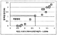
- Figure 1 is a graph showing the relationship between the yield point measured according to the component content of the present invention.
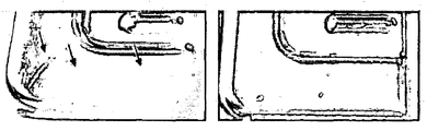
- Figure 2 is a photograph showing the surface shape of the fuel cell separator molded product molded from comparative steel and invention steel.
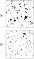
- FIG. 4 is a transmission electron micrograph of Comparative Steel 4 (a) and Inventive Steel 5 (b) of Tables 1 and 2.
- FIG. 4 is a transmission electron micrograph of Comparative Steel 4 (a) and Inventive Steel 5 (b) of Tables 1 and 2.
- Ferritic stainless steel for fuel cell separator having excellent formability and excellent surface quality has a weight%, more than C: 0 and less than 0.02%, more than N: 0 and less than 0.02%, more than Si: 0 and less than 0.4%, Mn: More than 0 and 0.2% or less, P: More than 0 and 0.04% or less, S: More than 0 and 0.02% or less, Cr: 25.0 to 32.0%, Cu: 0 to 1.0%, Ni: More than 0 and 0.8% or less, Ti: 0.01 or more One or more elements selected from the group consisting of 0.5% or less, Nb: 0.01 to 0.5% or less, V: 0.01 to 1.5% or less and Mo: 0 to 4%, W: 0 to 1% are further included. , Remainder Fe, and inevitably contains a composition.
- a cold rolled, annealed, pickled or cold rolled, bright annealed hot rolled coil made of hot rolling, annealing, and pickling having the above composition is repeatedly manufactured.
- composition range of the present invention and the reason for limitation thereof will be described in more detail.
- all% described below is weight%.
- the content is preferably made 0.02% or less.
- N is an element that forms a nitride and is present in an invasive form, and if excessively contained, the strength increases but is disadvantageous in elongation and yield point stretching. Therefore, the content is preferably made 0.02% or less.
- the composition ratio of Si is limited to 0.4% or less.
- Mn is an element that increases deoxidation, but MnS, which is an inclusion, reduces corrosion resistance, so the composition ratio of Mn is limited to 0.2% or less in the present invention.
- composition ratio of P is limited to 0.04% or less in the present invention.
- the present invention limits the composition ratio of S to 0.02% or less in consideration of this.
- Cr increases corrosion resistance in an acidic atmosphere in which a fuel cell operates, but decreases elongation, thereby inhibiting moldability, and therefore, the composition ratio of Cr is limited to 25% to 32%.
- Cu increases the corrosion resistance in the acidic atmosphere in which the fuel cell is operated, but when it exceeds 1%, the elongation is lowered and the moldability deteriorates, so it is limited to 1% or less.
- Ni When Ni is added in excess of 0.8%, formation of the material may be deteriorated due to Ni dissolution and elongation during fuel cell operation. Therefore, it is preferable to add Ni below 0.8%. In addition, when Ni is added in an amount of 0.3% or less, the Ni may more effectively act on soft nitriding of a material, thereby improving moldability. Therefore, it is more preferable that said Ni is more than 0 and 0.3% or less.
- Ti and Nb are effective elements for forming C and N in carbon as carbonitrides.
- Ti and Nb can increase the elongation of a material and are effective for suppressing yield point elongation.
- the composition ratio is limited to 0.01 to 0.5% or less in consideration of this.
- V is an element that forms carbonitrides and is effective for suppressing yield point stretching to improve moldability. When excessively added, the corrosion resistance and toughness decrease and are expensive, so the composition ratio of V is limited to 0.01 to 1.5%.
- Mo serves to increase the corrosion resistance in the operating environment atmosphere, but inferior in elongation lowering and economical efficiency of the material at the time of excessive addition, in the present invention limits the composition ratio of Mo to 0% to 5% or less.
- W has the effect of increasing the corrosion resistance and lowering the interfacial contact resistance in the acidic atmosphere in which the fuel cell operates, but decreases the formability due to the lowering of the elongation of the material when excessively added. Therefore, the present invention limits the composition ratio of W to 0 to 1.0% in consideration of this.
- Mo, W may be added one or more.
- the present invention in forming steel, the present invention adjusts the C, N, V, Ti, Nb content of the following formula (1) in the above composition range and adjusts it to 0.7 or less, and the yield point elongation of the material is 1.1. It is possible to manufacture steel materials within% and excellent in moldability.
- formula (1) is the result of putting the value of the weight% with respect to each component, for example, C, N, V, Ti, Nb.
- the present invention is first produced as a slab through the playing process of the alloy designed steel as described above. Subsequently, the slab is subjected to hot rolling after hot rolling, hot rolling annealing, and repeated cold annealing after cold rolling, thereby producing a cold rolled sheet having a final desired thickness.
- the cold rolling annealing temperature is preferably carried out at a temperature of 900 ⁇ 1100 °C.
- the cold rolling annealing temperature is higher than 1100 °C, the grains coarsen and the yield point elongation is improved. However, the elongation is deteriorated and the moldability is deteriorated. If the annealing temperature is 900 °C or less, the recrystallized texture does not develop, the moldability is disadvantageous.
- Table 1 shows the relationship between yield point stretching according to the present invention and a comparative example.
- Equation (1) shown in Table 1 below is as follows.
- Equation (1) 9.1C-1.76V + 5.37 (C + N) / Ti-1.22Nb
- yield point extension was measured with respect to a 0.2 mm cold rolled material.
- Ingots were prepared by dissolving alloys of the compositional components as shown in Table 1 at a vacuum induction rate of 50 kg capacity.
- the prepared ingot was hot rolled and then hot rolled to prepare a hot rolled steel sheet. Thereafter, the hot rolled steel sheet was cold rolled to a final thickness of 0.2 mm to prepare a cold rolled sheet material.
- the produced cold rolled sheet was subjected to rapid cooling after annealing at a heating temperature of 1000 ° C.
- the prepared cold rolled sheet was subjected to a tensile test of a crosshead speed of 20 mm / min by processing the specimen in a direction parallel to the rolling direction after the pickling standard JIS 13B after pickling. The yield point elongation according to each material component was measured through the tensile test.
- Figure 1 shows the results of comparing the yield point elongation (%) and formula (1) of the 0.2 mm thick cold rolled annealing sheet according to Table 1
- Figure 2 is a comparative steel 5 (left) and the invention steel 1 ( The result shows the surface shape after stamping and forming a fuel cell separator with the electrode effective area of 200 cm 2 of cold rolled steel (right) and annealing heat treatment at 1000 ° C. after annealing heat treatment.
- Comparative Steel 5 the surface of the indented strain strain appears after processing, whereas invented steel 1 can obtain a good surface quality without the strainer strain defect.
- inventive steel 1 was able to obtain better moldability than comparative steel 5.
- invented steel 1 (1.1% yield point and 0.7 in formula (1)) was formed compared to comparative steel 5 (1.2% yield point and 1.16 in formula (1)). It was confirmed that the sex is improved.
- Yield point stretching is an item that can confirm the formability, and when the yield point extension exceeds 1.1%, local stress concentration is applied to the processing deformation part (arrow of FIG. 2) during processing steel grade for use in a fuel cell separator. This problem occurs due to the deepening and the formation of streaks. That is, when yield point elongation is more than 1.1% and the value according to Formula (1) exceeds 0.7, moldability will fall.
- the yield point stretching is preferably 1.1% or less.
- the yield point stretching is performed by adjusting the content of the invasive alloying elements (C, N) and the carbon, nitride forming elements V, Ti, and Nb by adjusting the appropriate contents.
- the value calculated by (1) was adjusted to 0.7 or less, it was found that yield point elongation became small.
- the yield point extension exceeds 1.1%.
- Figure 1 shows the results of comparing the yield point elongation (%) of the 0.2 mm thick cold-rolled annealing sheet according to the component content of the present invention in comparison with the value of the formula (1).
- the stainless steel according to the present embodiment may include (Ti, Nb) (C, N) precipitates, Nb 2 C precipitates and Laves phase (Fe 2 Nb) precipitates.
- the surface of the stainless steel may be covered by (Ti, Nb) (C, N) precipitates, Nb 2 C precipitates and Laves phase (Fe 2 Nb) precipitates (total precipitates), wherein the total per unit area of the stainless steel The precipitate area fraction is 3.5% or less, and the (Ti, Nb) (C, N) / total precipitate area fraction (%), which is the ratio of (Ti, Nb) (C, N) precipitates to the total precipitates, is 62% or more. Can be.
- the (Ti, Nb) (C, N) precipitates exist as one precipitate phase, and the (Ti, Nb) (C, N) precipitates effectively fix N and C in the substrate, thereby yielding a yield point of stainless steel. Stretching can be improved to improve moldability.
- the total precipitate area fraction means the extent to which the total precipitate is covered with respect to the total area of the steel grade (after annealing of 0.2 mm cold rolled material) used as a sample.
- Table 2 shows the results of analyzing the total precipitate measured by transmission electron microscopy of the total precipitate and the total precipitate (100 nm 2 ) per unit area for the steel grades of Table 1 by an image analyzer.
- each of the steel grades were randomly measured five times with a transmission tram microscope (TEM) while changing the position for each steel grade, and the values shown in Table 2 were measured five times for one sample (steel grade). Average value.
- TEM transmission tram microscope
- the precipitates When precipitates are increased in stainless steel, the precipitates can cure the substrate of the steel species. Therefore, the increase of the precipitate may increase the yield point, when the total amount of the precipitate (total precipitate) exceeds 3.5% in an area fraction per unit area may reduce the formability of the steel species.
- the ratio of (Ti, Nb) (C, N) / total precipitate area (%), which is the ratio of (Ti, Nb) (C, N) precipitates to the total precipitates is 62% or more, When Nb) (C, N) /% of total precipitate area is less than 62%, C and N cannot be dissolved to increase yield point elongation and lower moldability.
- Table 3 shows the results of the relationship between yield point stretching for C + N according to the present invention and the comparative example.
- the comparative steel and the inventive steel of Table 3 were also confirmed by the same method using the same 0.2mm cold rolled material as in Table 1.
- C + N may be 0.032% or less by weight.
- the solid solution C and N content may be increased, and a large amount of precipitates may be formed to increase yield point elongation and reduce moldability.
- the value of C + N exceeds 0.032%, the amount of Ti, Nb and V must be excessively added to lower the solid solution C and N content, which increases yield point elongation.
- the softness of the material due to excessive carbonitride formation may be inhibited, thereby lowering the overall formability.
- Table 3 shows the results of confirming the yield point stretching for Comparative Steels 9 to 11 and Inventive Steels 8 to 10. As shown in Comparative Steels 9 to 11, in the case of C + N of 0.0377, 0.038 and 0.034, it was confirmed that yield point elongation was 2.5, 2 and 1.5, respectively, and was disadvantageous in formability. In addition, it was confirmed that the values according to Equation (1) in Comparative Steels 9 to 11 also exceeded 0.7 as 1.677, 3.202, and 2.622, respectively.
- C + N is 0.012, 0.018 and 0.032, respectively, the yield point was confirmed that 0.5, 0.4 and 0 are all 1.1% or less.
- the inventive steels 8 to 10 have values of 0.1, -0.041, and 0.697, respectively, equal to or less than 0.7, and these inventive steels 8 to 10 have excellent surface quality and formability and are suitable for fuel cell separators. It could be confirmed that it can be used. That is, as shown in Table 3, it is preferable to manage the total amount of C + N as the precipitated element, and considering the formability, yield point elongation and production cost of stainless steel, C + N is preferably managed to 0.032% or less.
- C + N is preferably managed to 0.032% or less.
- FIG. 4 is a transmission electron micrograph of Comparative Steel 4 (a) and Inventive Steel 5 (b) of Tables 1 and 2.
- FIG. 4 is a transmission electron micrograph of Comparative Steel 4 (a) and Inventive Steel 5 (b) of Tables 1 and 2.
- FIG. 4 in the case of FIG. 4A, which is Comparative Steel 4, the proportion of total precipitates per unit area (per 100 nm 2 ) of stainless steel is 5.6% in area fraction (%), and FIG. In the case of (b) of 4, the proportion of the total precipitate per unit area (per 100 nm 2 ) of the stainless steel was 3.2% as the area fraction (%).
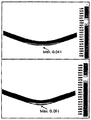
- FIG. 3 shows a computer simulation using the finite element method for the true strain distribution in the longitudinal direction of the specimen at the same stroke of the punch during the V-bending test when there is no yield point extension (left) and when the yield point extension is 4% (right).
- yield point stretching a maximum strain of 0.061 in the bending strain concentration area is shown, and a strain of 0.02 (about 2% of the nominal strain) is increased compared to the test of a material without yield point stretching of 0.041.
- the deformation shape of the specimen shows a rather bent shape rather than a relatively smooth curve, which does not induce the dispersion of the yield point stretching from the surface of the material during the bending of the material in the longitudinal direction of the specimen.
- the removal of the yield point can be said to be an essential factor to improve the formability when forming the fuel cell separator.
- a method of removing the final rolled sheet material by about 0.5 to 2% by cold rolling or leveling is generally known.
- the additional process such as cold rolling or leveling can increase the manufacturing cost of the material, there is a problem that these yield stretching may occur again after a certain time.
- the present invention further comprises the step of forming a thin plate for the fuel cell separator plate of the stainless steel alloy designed in the above composition can finally obtain the stainless steel for polymer fuel cell separator plate.
Landscapes
- Chemical & Material Sciences (AREA)
- Engineering & Computer Science (AREA)
- Materials Engineering (AREA)
- Organic Chemistry (AREA)
- Metallurgy (AREA)
- Mechanical Engineering (AREA)
- Crystallography & Structural Chemistry (AREA)
- Physics & Mathematics (AREA)
- Thermal Sciences (AREA)
- Life Sciences & Earth Sciences (AREA)
- Manufacturing & Machinery (AREA)
- Sustainable Development (AREA)
- Sustainable Energy (AREA)
- Chemical Kinetics & Catalysis (AREA)
- Electrochemistry (AREA)
- General Chemical & Material Sciences (AREA)
- Heat Treatment Of Sheet Steel (AREA)
- Fuel Cell (AREA)
Description
| 구분 | C | Si | Al | P | S | Cr | Cu | Ti | Nb | V | N | 기타 | 항복점연신(%) | 식(1) |
| 비교강1 | 0.0077 | 0.113 | 0.05 | <0.003 | <0.002 | 30.13 | 0.49 | 0.05 | 0.24 | 0.41 | 0.0130 | 1.8 | 1.28 | |
| 비교강2 | 0.0082 | 0.119 | 0.05 | <0.003 | <0.002 | 30.06 | - | 0.05 | 0.25 | 0.41 | 0.0160 | 2.0 | 1.65 | |
| 비교강3 | 0.0072 | 0.113 | 0.04 | <0.003 | <0.002 | 28.02 | - | 0.05 | 0.25 | 0.41 | 0.0150 | 1.5 | 1.42 | |
| 비교강4 | 0.0082 | 0.110 | 0.05 | <0.003 | <0.002 | 28.05 | 0.49 | 0.05 | 0.24 | 0.41 | 0.0160 | 2.1 | 1.66 | |
| 비교강5 | 0.0036 | 0.126 | 0.03 | <0.003 | <0.002 | 29.90 | 0.51 | 0.04 | 0.35 | 0 | 0.0080 | 1.2 | 1.16 | |
| 비교강6 | 0.0035 | 0.126 | 0.01 | <0.003 | <0.002 | 30.27 | 0.49 | 0.04 | 0.37 | 0 | 0.0084 | 1.8 | 1.18 | |
| 비교강7 | 0.0083 | 0.130 | 0.02 | <0.003 | <0.002 | 29.60 | 0.51 | 0.05 | 0.50 | 0.40 | 0.0170 | 2.0 | 1.48 | |
| 비교강8 | 0.0065 | 0.113 | 0.02 | <0.003 | <0.002 | 29.89 | 0.51 | 0.05 | 0.25 | 0.40 | 0.0190 | 2.3 | 1.79 | |
| 발명강1 | 0.0047 | 0.112 | 0.05 | <0.003 | <0.002 | 28.01 | - | 0.05 | 0.15 | 0.3 | 0.0080 | 1.1 | 0.7 | |
| 발명강2 | 0.0070 | 0.084 | 0.05 | <0.003 | <0.002 | 30.27 | - | 0.11 | 0.08 | 0.50 | 0.0190 | 0.7 | 0.36 | |
| 발명강3 | 0.0060 | 0.111 | 0.05 | <0.003 | <0.002 | 30.43 | - | 0.10 | 0.24 | 0.50 | 0.0150 | 0.2 | 0.01 | |
| 발명강4 | 0.0060 | 0.135 | 0.05 | <0.003 | <0.002 | 30.43 | - | 0.18 | 0.08 | 0.49 | 0.0170 | 0.1 | -0.22 | |
| 발명강5 | 0.0060 | 0.126 | 0.05 | <0.003 | <0.002 | 30.49 | - | 0.20 | 0.24 | 0.50 | 0.0170 | 0.01 | -0.50 | |
| 발명강6 | 0.0060 | 0.116 | 0.05 | <0.003 | <0.002 | 30.20 | 0.51 | 0.20 | 0.24 | 0.50 | 0.0170 | 0.0 | -0.50 | |
| 발명강7 | 0.0060 | 0.093 | 0.05 | <0.003 | <0.002 | 30.44 | - | 0.16 | 0.20 | 0.47 | 0.0150 | 1Mo | 0.0 | -0.31 |
| 구분 | 전체석출물 | 단위면적당 전체석출물 면적분율 (%) | (Ti,Nb)(C,N)/전체석출물 면적분율 (%) |
| 비교강1 | (Ti,Nb)(C,N),Nb2C,(Fe,Cr)2Nb | 4.0 | 52 |
| 비교강2 | (Ti,Nb)(C,N), Nb2C,(Fe,Cr)2Nb | 4.2 | 41 |
| 비교강3 | (Ti,Nb)(C,N),Nb2C,(Fe,Cr)2Nb | 4.2 | 55 |
| 비교강4 | (Ti,Nb)(C,N),Nb2C,(Fe,Cr)2Nb | 5.6 | 52 |
| 비교강5 | (Ti,Nb)(C,N),Nb2C,(Fe,Cr)2Nb | 3.7 | 57 |
| 비교강6 | (Ti,Nb)(C,N),Nb2C,(Fe,Cr)2Nb | 5.1 | 50 |
| 비교강7 | (Ti,Nb)(C,N), Nb2C,(Fe,Cr)2Nb | 4.2 | 49 |
| 비교강8 | (Ti,Nb)(C,N), Nb2C,(Fe,Cr)2Nb | 4.1 | 44 |
| 발명강1 | (Ti,Nb)(C,N), Nb2C,(Fe,Cr)2Nb | 1.8 | 65 |
| 발명강2 | (Ti,Nb)(C,N), Nb2C | 2.4 | 70 |
| 발명강3 | (Ti,Nb)(C,N), Nb2C,(Fe,Cr)2Nb | 2.8 | 80 |
| 발명강4 | (Ti,Nb)(C,N), Nb2C,(Fe,Cr)2Nb | 3.4 | 82 |
| 발명강5 | (Ti,Nb)(C,N),Nb2C,(Fe,Cr)2Nb | 3.2 | 82 |
| 발명강6 | (Ti,Nb)(C,N), Nb2C,(Fe,Cr)2Nb | 3 | 83 |
| 발명강7 | (Ti,Nb)(C,N), Nb2C,(Fe,Cr)2Nb | 2.9 | 82 |
| 구분 | C | Si | Cr | Ti | Nb | V | N | C+N | 항복점연신(%) | 식(1) |
| 비교강9 | 0.0177 | 0.113 | 30.13 | 0.08 | 0.24 | 0.41 | 0.02 | 0.0377 | 2.5 | 1.677 |
| 비교강10 | 0.022 | 0.119 | 30.06 | 0.05 | 0.25 | 0.44 | 0.016 | 0.038 | 2 | 3.202 |
| 비교강11 | 0.019 | 0.113 | 28.02 | 0.05 | 0.25 | 0.51 | 0.015 | 0.034 | 1.5 | 2.622 |
| 발명강8 | 0.005 | 0.112 | 28.01 | 0.08 | 0.024 | 0.41 | 0.007 | 0.012 | 0.5 | 0.100 |
| 발명강9 | 0.007 | 0.09 | 30.27 | 0.11 | 0.056 | 0.52 | 0.011 | 0.018 | 0.4 | -0.041 |
| 발명강10 | 0.018 | 0.111 | 30.43 | 0.1 | 0.25 | 0.5 | 0.014 | 0.032 | 0 | 0.697 |
Claims (11)
- 중량 %로, C: 0 초과 0.02% 이하, N: 0 초과 0.02% 이하, Si: 0 초과 0.4% 이하, Mn: 0 초과 0.2 %이하, P: 0 초과 0.04% 이하, S: 0 초과 0.02% 이하, Cr:25.0~32.0%, Cu:0~1.0%, Ni: 0 초과 0.8% 이하, Ti:0.01~0.5% 이하, Nb:0.01~0.5% 이하, V:0.01~1.5% 이하, 잔부 Fe 및 불가피하게 함유되는 원소로 이루어지고, 하기 식(1)을 만족하며 항복점 연신이 1.1% 이하인 표면품질 및 성형성이 우수한 연료전지 분리판용 스테인리스강.(1) 9.1C-1.76V+5.37(C+N)/Ti - 1.22Nb ≤ 0.7
- 제1항에 있어서,상기 스테인리스강은 중량 %로, Mo:0~4%, W:0~1%로 이루어지는 군에서 선택되는 1종 또는 2종의 원소가 더 포함되는 표면품질 및 성형성이 우수한 연료전지 분리판용 스테인리스강.
- 제1항에 있어서,상기 스테인리스강의 항복점 연신은 0.2mm 이하의 냉연재로 성형된, 표면품질 및 성형성이 우수한 연료전지 분리판용 스테인리스강.
- 제1항에 있어서,상기 스테인리스강은 중량 %로, Ni: 0초과 0.3% 이하로 포함하는 표면품질 및 성형성이 우수한 연료전지 분리판용 스테인리스강.
- 제1항에 있어서,상기 스테인리스강은 (Ti,Nb)(C,N)석출물을 포함하고, 상기 스테인리스강에서 단위면적당 전체석출물의 면적분율(%)은 3.5% 이하이되, (Ti,Nb)(C,N)석출물/전체석출물의 면적분율(%)은 62% 이상인 표면품질 및 성형성이 우수한 연료전지 분리판용 스테인리스강.
- 제1항에 있어서,상기 스테인리스강은 중량 %로, C+N은 0.032% 이하인 표면품질 및 성형성이 우수한 연료전지 분리판용 스테인리스강.
- 중량 %로, C: 0 초과 0.02% 이하, N: 0 초과 0.02% 이하, Si: 0 초과 0.4% 이하, Mn: 0 초과 0.2 %이하, P: 0 초과 0.04% 이하, S: 0 초과 0.02% 이하, Cr: 25.0~32.0%, Cu:0~1.0%, Ni: 0 초과 0.8% 이하, Ti:0.01~0.5% 이하, Nb:0.01~0.5% 이하, V:0.01~1.5% 이하, 잔부 Fe 및 불가피하게 함유되는 원소로 이루어지고, 하기 식(1)을 만족하는 조성의 스테인리스강을 연주, 열연 및 냉연공정 후에 냉연 소둔열처리를 실시하되, 항복점 연신을 1.1% 이하로 제어하고, 상기 냉연공정 후의 냉연 소둔온도를 900~1100℃의 온도조건에서 제어하는 표면품질 및 성형성이 우수한 연료전지 분리판용 스테인리스강 제조방법.(1) 9.1C-1.76V+5.37(C+N)/Ti - 1.22Nb ≤ 0.7
- 제7항에 있어서,상기 스테인리스강은 중량 %로, Mo:0~4%, W:0~1%로 이루어지는 군에서 선택되는 1종 또는 2종의 원소가 더 포함되는 표면품질 및 성형성이 우수한 연료전지 분리판용 스테인리스강 제조방법.
- 제7항에 있어서,스테인리스강을 연료전지 분리판용으로 박판 성형하는 단계를 더 포함하는 표면품질 및 성형성이 우수한 연료전지 분리판용 스테인리스강 제조방법.
- 제7항에 있어서,상기 스테인리스강은 중량 %로, Ni: 0초과 0.3% 이하이고, C+N은 0.032% 이하로 포함하는 표면품질 및 성형성이 우수한 연료전지 분리판용 스테인리스강 제조방법.
- 제7항에 있어서,상기 스테인리스강은 (Ti,Nb)(C,N)석출물을 포함하고, 상기 스테인리스강에서 단위면적당 전체석출물의 면적분율(%)은 3.5% 이하이되, (Ti,Nb)(C,N)석출물/전체석출물의 면적분율(%)은 62% 이상인 표면품질 및 성형성이 우수한 연료전지 분리판용 스테인리스강 제조방법.
Priority Applications (6)
| Application Number | Priority Date | Filing Date | Title |
|---|---|---|---|
| DE112012005474.1T DE112012005474T5 (de) | 2011-12-26 | 2012-12-26 | Rostfreier Stahl mit hochwertiger Oberflächenqualität und Formbarkeit für Brennstoffzellen-Trennplatten und Verfahren zur Herstellung desselben |
| US14/368,689 US9777344B2 (en) | 2011-12-26 | 2012-12-26 | Stainless steel having superior surface quality and moldability for fuel cell divider sheet, and method for manufacturing same |
| CA2859781A CA2859781C (en) | 2011-12-26 | 2012-12-26 | Stainless steel having superior surface quality and moldability for fuel cell divider sheet, and method for manufacturing same |
| CN201280064621.5A CN104011244B (zh) | 2011-12-26 | 2012-12-26 | 表面品质及成型性优良的燃料电池分离板用不锈钢及其制造方法 |
| JP2014548691A JP5873572B2 (ja) | 2011-12-26 | 2012-12-26 | 表面品質及び成形性に優れた燃料電池分離板用ステンレス鋼及びその製造方法 |
| KR1020147017676A KR101623289B1 (ko) | 2011-12-26 | 2012-12-26 | 표면품질 및 성형성이 우수한 연료전지 분리판용 스테인리스강 및 그 제조방법 |
Applications Claiming Priority (2)
| Application Number | Priority Date | Filing Date | Title |
|---|---|---|---|
| KR10-2011-0142160 | 2011-12-26 | ||
| KR20110142160 | 2011-12-26 |
Publications (1)
| Publication Number | Publication Date |
|---|---|
| WO2013100600A1 true WO2013100600A1 (ko) | 2013-07-04 |
Family
ID=48697949
Family Applications (1)
| Application Number | Title | Priority Date | Filing Date |
|---|---|---|---|
| PCT/KR2012/011515 Ceased WO2013100600A1 (ko) | 2011-12-26 | 2012-12-26 | 표면품질 및 성형성이 우수한 연료전지 분리판용 스테인리스강 및 그 제조방법 |
Country Status (7)
| Country | Link |
|---|---|
| US (1) | US9777344B2 (ko) |
| JP (1) | JP5873572B2 (ko) |
| KR (1) | KR101623289B1 (ko) |
| CN (1) | CN104011244B (ko) |
| CA (1) | CA2859781C (ko) |
| DE (1) | DE112012005474T5 (ko) |
| WO (1) | WO2013100600A1 (ko) |
Cited By (1)
| Publication number | Priority date | Publication date | Assignee | Title |
|---|---|---|---|---|
| CN103972571A (zh) * | 2014-04-03 | 2014-08-06 | 上海华篷防爆科技有限公司 | 含有一种聚合物电解质膜的固态氢发电装置 |
Families Citing this family (7)
| Publication number | Priority date | Publication date | Assignee | Title |
|---|---|---|---|---|
| KR101742088B1 (ko) | 2015-12-23 | 2017-06-01 | 주식회사 포스코 | 친수성 및 접촉저항이 향상된 고분자 연료전지 분리판용 스테인리스강 및 이의 제조 방법 |
| JP6323623B1 (ja) * | 2016-06-10 | 2018-05-16 | Jfeスチール株式会社 | 燃料電池のセパレータ用ステンレス鋼板およびその製造方法 |
| CN109312422B (zh) * | 2016-06-10 | 2020-06-23 | 杰富意钢铁株式会社 | 燃料电池的隔板用不锈钢板及其制造方法 |
| KR102206415B1 (ko) | 2016-09-02 | 2021-01-22 | 제이에프이 스틸 가부시키가이샤 | 페라이트계 스테인리스강 |
| CN110678566A (zh) | 2017-05-26 | 2020-01-10 | 杰富意钢铁株式会社 | 铁素体系不锈钢 |
| KR102326043B1 (ko) | 2019-12-19 | 2021-11-15 | 주식회사 포스코 | 내식성이 우수한 고분자 연료전지 분리판용 스테인리스강 |
| KR20240087432A (ko) * | 2022-12-12 | 2024-06-19 | 주식회사 포스코 | 성형성이 향상된 페라이트계 스테인리스강 및 그 제조방법 |
Citations (5)
| Publication number | Priority date | Publication date | Assignee | Title |
|---|---|---|---|---|
| JPH09157801A (ja) * | 1995-10-05 | 1997-06-17 | Hitachi Metals Ltd | 固体電解質型燃料電池セパレーター用鋼 |
| JP2004018950A (ja) * | 2002-06-17 | 2004-01-22 | Jfe Steel Kk | 耐高温酸化性および耐高温塩害性に優れたCr含有鋼 |
| JP2004076154A (ja) * | 2002-06-17 | 2004-03-11 | Jfe Steel Kk | 耐食性、高温強度および耐高温酸化性に優れたフェライト系ステンレス鋼 |
| JP2011047043A (ja) * | 2009-07-30 | 2011-03-10 | Jfe Steel Corp | 導電性と延性に優れた燃料電池セパレータ用ステンレス鋼およびその製造方法 |
| KR20110115619A (ko) * | 2009-08-31 | 2011-10-21 | 제이에프이 스틸 가부시키가이샤 | 내열성이 우수한 페라이트계 스테인리스강 |
Family Cites Families (3)
| Publication number | Priority date | Publication date | Assignee | Title |
|---|---|---|---|---|
| WO2003106722A1 (ja) | 2002-06-14 | 2003-12-24 | Jfeスチール株式会社 | 耐熱性フェライト系ステンレス鋼およびその製造方法 |
| DE112007003189T5 (de) | 2006-12-28 | 2009-12-17 | Posco, Pohang | Verfahren zur Verbesserung von Oberflächeneigenschaften der rostfreien Stähle für Bipolarplatten von Polymer-Elektrolyt-Membran-Brennstoffzellen |
| KR100993412B1 (ko) | 2008-12-29 | 2010-11-09 | 주식회사 포스코 | 고분자 연료전지 분리판용 스테인리스강 및 그 제조방법 |
-
2012
- 2012-12-26 CN CN201280064621.5A patent/CN104011244B/zh active Active
- 2012-12-26 WO PCT/KR2012/011515 patent/WO2013100600A1/ko not_active Ceased
- 2012-12-26 KR KR1020147017676A patent/KR101623289B1/ko active Active
- 2012-12-26 JP JP2014548691A patent/JP5873572B2/ja active Active
- 2012-12-26 US US14/368,689 patent/US9777344B2/en active Active
- 2012-12-26 CA CA2859781A patent/CA2859781C/en active Active
- 2012-12-26 DE DE112012005474.1T patent/DE112012005474T5/de active Pending
Patent Citations (5)
| Publication number | Priority date | Publication date | Assignee | Title |
|---|---|---|---|---|
| JPH09157801A (ja) * | 1995-10-05 | 1997-06-17 | Hitachi Metals Ltd | 固体電解質型燃料電池セパレーター用鋼 |
| JP2004018950A (ja) * | 2002-06-17 | 2004-01-22 | Jfe Steel Kk | 耐高温酸化性および耐高温塩害性に優れたCr含有鋼 |
| JP2004076154A (ja) * | 2002-06-17 | 2004-03-11 | Jfe Steel Kk | 耐食性、高温強度および耐高温酸化性に優れたフェライト系ステンレス鋼 |
| JP2011047043A (ja) * | 2009-07-30 | 2011-03-10 | Jfe Steel Corp | 導電性と延性に優れた燃料電池セパレータ用ステンレス鋼およびその製造方法 |
| KR20110115619A (ko) * | 2009-08-31 | 2011-10-21 | 제이에프이 스틸 가부시키가이샤 | 내열성이 우수한 페라이트계 스테인리스강 |
Cited By (1)
| Publication number | Priority date | Publication date | Assignee | Title |
|---|---|---|---|---|
| CN103972571A (zh) * | 2014-04-03 | 2014-08-06 | 上海华篷防爆科技有限公司 | 含有一种聚合物电解质膜的固态氢发电装置 |
Also Published As
| Publication number | Publication date |
|---|---|
| KR101623289B1 (ko) | 2016-05-20 |
| US20140338796A1 (en) | 2014-11-20 |
| DE112012005474T5 (de) | 2014-09-04 |
| CN104011244A (zh) | 2014-08-27 |
| JP5873572B2 (ja) | 2016-03-01 |
| US9777344B2 (en) | 2017-10-03 |
| KR20140105791A (ko) | 2014-09-02 |
| CN104011244B (zh) | 2016-12-21 |
| JP2015507091A (ja) | 2015-03-05 |
| CA2859781A1 (en) | 2013-07-04 |
| CA2859781C (en) | 2021-03-02 |
Similar Documents
| Publication | Publication Date | Title |
|---|---|---|
| CN100351415C (zh) | 成形性优良的铁素体系不锈钢板及其制造方法 | |
| KR101623289B1 (ko) | 표면품질 및 성형성이 우수한 연료전지 분리판용 스테인리스강 및 그 제조방법 | |
| US20230257860A1 (en) | Method of producing a non-oriented electrical steel sheet | |
| WO2020136993A1 (ja) | 無方向性電磁鋼板およびその製造方法 | |
| JP5549640B2 (ja) | 高炭素薄鋼板およびその製造方法 | |
| WO2012087045A2 (ko) | 저철손 고강도 무방향성 전기강판 및 그 제조방법 | |
| CN105331883A (zh) | 一种双面搪瓷用热轧高强度中厚板及其制造方法 | |
| CN100999050A (zh) | 低铁损高磁感冷轧无取向电工钢板的生产方法 | |
| WO2018088652A1 (ko) | 내수소취성이 개선된 오스테나이트계 스테인리스강 및 이를 포함하는 고압 수소 가스용 용기 | |
| WO2012091394A9 (ko) | 고내식 마르텐사이트 스테인리스강 및 그 제조방법 | |
| WO2020111570A1 (ko) | 자성이 우수한 무방향성 전기강판 및 그 제조방법 | |
| WO2019117430A1 (ko) | 고온 내산화성이 우수한 페라이트계 스테인리스강 및 그 제조방법 | |
| CN101041222A (zh) | 一种冷轧无取向电工钢板及其生产方法 | |
| WO2017111251A1 (ko) | 내크립 특성 및 인장강도가 향상된 오스테나이트계 스테인리스강 및 이의 제조 방법 | |
| WO2018110779A1 (ko) | 강도 및 연성이 우수한 저합금 강판 | |
| WO2016111388A1 (ko) | 인장강도 1300MPa 이상의 초고강도 도금강판 및 이의 제조방법 | |
| WO2020111884A1 (ko) | 수소지연파괴특성 및 점용접성이 우수한 열간 프레스용 알루미늄계 도금 강판 및 그 제조방법 | |
| WO2019059660A1 (ko) | 강도 및 연성이 우수한 저합금 강판 및 이의 제조방법 | |
| WO2017052005A1 (ko) | 페라이트계 스테인리스강 및 이의 제조 방법 | |
| WO2018117489A1 (ko) | 강도 및 내산성이 우수한 페라이트계 스테인리스강 및 이의 제조 방법 | |
| WO2019039824A1 (ko) | 법랑용 냉연강판 및 그 제조방법 | |
| WO2017209431A1 (ko) | 내식성 및 가공성이 향상된 오스테나이트계 스테인리스강 및 이의 제조 방법 | |
| CN118668129A (zh) | 一种高强度低铁损无取向电工钢板及其制造方法 | |
| EP4585706A1 (en) | Non-oriented electromagnetic steel sheet and production method for same | |
| WO2019045188A1 (ko) | 방열성 및 가공성이 향상된 페라이트계 스테인리스강 및 이의 제조 방법 |
Legal Events
| Date | Code | Title | Description |
|---|---|---|---|
| 121 | Ep: the epo has been informed by wipo that ep was designated in this application |
Ref document number: 12863941 Country of ref document: EP Kind code of ref document: A1 |
|
| ENP | Entry into the national phase |
Ref document number: 2859781 Country of ref document: CA |
|
| ENP | Entry into the national phase |
Ref document number: 2014548691 Country of ref document: JP Kind code of ref document: A |
|
| WWE | Wipo information: entry into national phase |
Ref document number: 14368689 Country of ref document: US |
|
| ENP | Entry into the national phase |
Ref document number: 20147017676 Country of ref document: KR Kind code of ref document: A |
|
| WWE | Wipo information: entry into national phase |
Ref document number: 1120120054741 Country of ref document: DE Ref document number: 112012005474 Country of ref document: DE |
|
| 122 | Ep: pct application non-entry in european phase |
Ref document number: 12863941 Country of ref document: EP Kind code of ref document: A1 |
|
| 122 | Ep: pct application non-entry in european phase |
Ref document number: 12863941 Country of ref document: EP Kind code of ref document: A1 |