WO2013100328A1 - 이미지 센싱 소자 및 이미지 센싱 방법 - Google Patents
이미지 센싱 소자 및 이미지 센싱 방법 Download PDFInfo
- Publication number
- WO2013100328A1 WO2013100328A1 PCT/KR2012/007914 KR2012007914W WO2013100328A1 WO 2013100328 A1 WO2013100328 A1 WO 2013100328A1 KR 2012007914 W KR2012007914 W KR 2012007914W WO 2013100328 A1 WO2013100328 A1 WO 2013100328A1
- Authority
- WO
- WIPO (PCT)
- Prior art keywords
- reference value
- preset
- image
- time
- brightness
- Prior art date
- Legal status (The legal status is an assumption and is not a legal conclusion. Google has not performed a legal analysis and makes no representation as to the accuracy of the status listed.)
- Ceased
Links
Images


Classifications
-
- H—ELECTRICITY
- H10—SEMICONDUCTOR DEVICES; ELECTRIC SOLID-STATE DEVICES NOT OTHERWISE PROVIDED FOR
- H10F—INORGANIC SEMICONDUCTOR DEVICES SENSITIVE TO INFRARED RADIATION, LIGHT, ELECTROMAGNETIC RADIATION OF SHORTER WAVELENGTH OR CORPUSCULAR RADIATION
- H10F39/00—Integrated devices, or assemblies of multiple devices, comprising at least one element covered by group H10F30/00, e.g. radiation detectors comprising photodiode arrays
- H10F39/10—Integrated devices
- H10F39/12—Image sensors
- H10F39/18—Complementary metal-oxide-semiconductor [CMOS] image sensors; Photodiode array image sensors
- H10F39/186—Complementary metal-oxide-semiconductor [CMOS] image sensors; Photodiode array image sensors having arrangements for blooming suppression
-
- H—ELECTRICITY
- H04—ELECTRIC COMMUNICATION TECHNIQUE
- H04N—PICTORIAL COMMUNICATION, e.g. TELEVISION
- H04N25/00—Circuitry of solid-state image sensors [SSIS]; Control thereof
- H04N25/50—Control of the SSIS exposure
- H04N25/57—Control of the dynamic range
-
- H—ELECTRICITY
- H04—ELECTRIC COMMUNICATION TECHNIQUE
- H04N—PICTORIAL COMMUNICATION, e.g. TELEVISION
- H04N23/00—Cameras or camera modules comprising electronic image sensors; Control thereof
- H04N23/70—Circuitry for compensating brightness variation in the scene
- H04N23/76—Circuitry for compensating brightness variation in the scene by influencing the image signals
-
- H—ELECTRICITY
- H10—SEMICONDUCTOR DEVICES; ELECTRIC SOLID-STATE DEVICES NOT OTHERWISE PROVIDED FOR
- H10F—INORGANIC SEMICONDUCTOR DEVICES SENSITIVE TO INFRARED RADIATION, LIGHT, ELECTROMAGNETIC RADIATION OF SHORTER WAVELENGTH OR CORPUSCULAR RADIATION
- H10F39/00—Integrated devices, or assemblies of multiple devices, comprising at least one element covered by group H10F30/00, e.g. radiation detectors comprising photodiode arrays
- H10F39/10—Integrated devices
- H10F39/12—Image sensors
Definitions
- the present invention relates to an image sensing device and an image sensing method, and more particularly, to an image sensing device and an image sensing method capable of extending a dynamic range expressing brightness of light in an image capturing device such as a digital camera. .
- Dynamic range is one of the determinants of image sensor performance. It is an index that indicates how weak and strong light signals can be processed into images. That is, it means the saturation level of the pixel with respect to the signal noise level of the pixel, and is given by the following equation.
- D represents the dynamic range of the image sensor
- Noise represents the signal noise
- Saturation-level represents the saturation level of the pixel.
- the dynamic range is about 5,000 and the dB is about 75 dB.
- the exposure time for the input light can be adjusted to distinguish each of them.
- there is a limit in distinguishing between dark and bright areas by adjusting the exposure time and therefore, it is required to widen the dynamic range.
- a method of producing a high dynamic range image by combining a plurality of images taken while changing the exposure time in a conventional imaging device has been proposed. That is, the information of the bright part is obtained by shortening the exposure time, and the information of the dark area is obtained from the image with the long exposure time, and then the information is combined to obtain an image of high dynamic range.
- this method has the advantage of using an existing imaging device, but there is a problem in that the shooting time is excessively long because it is necessary to take several times while changing the exposure time.
- 1 a method of obtaining multiple exposure image information by sampling several times during a long shooting time, 2 adjusting the exposure time electronically according to the brightness, 3 resetting each time the brightness is saturated And save the number of times.
- 1 method has a problem that the number of shooting time is limited, 2 method has a problem that the adjustment of the exposure time is complicated, and 3 method has a problem that the circuit is complicated and the error is likely to occur due to the reset time, etc. have.
- Patent Document 1 Korean Patent Publication No. 10-2008-0043635
- Patent Document 2 Japanese Patent Application Laid-Open No. 2011-066795
- Patent Document 3 US Patent No. 7079178
- An object of the present invention is to provide an image sensing device and an image sensing method that can solve the above problems and extend the dynamic range.
- An optical sensor unit comprising a plurality of pixels for converting light reflected by a subject into an electrical signal and generating an output value; A comparison unit determining whether an output value of each of the plurality of pixels reaches a preset reference value during a preset maximum shooting time; A clock unit configured to measure the arrival time when the output value reaches the preset reference value during the preset first photographing time; And a memory unit for calculating and storing the brightness of the image by using the measured value determined by the comparison unit and the clock unit.
- the clock unit When the output value does not reach the preset reference value during the preset maximum shooting time, the clock unit generates a correction value by lowering the preset reference value, but the output value corresponding to the correction value and the preset reference value does not correspond. And a reference value correction unit for generating the correction value until such time as possible.
- the optical sensor unit may include a micro lens that focuses the input light; A color filter extracting a specific color signal from signals input from the micro lens; And a substrate configured to convert the extracted color signal into the electrical signal and output the converted electrical signal.
- the color filter may include at least one of a primary color filter, a complementary color filter, an infrared filter, and a low pass filter.
- the preset reference value may be a saturation output value of the optical sensor.
- the comparison unit may include at least one capacitor, and compares a voltage value or a current value generated by the charge accumulated in the optical sensor unit with a preset reference value.
- It may include an image brightness calculation unit for calculating the brightness of the image by the following equation (1) using the arrival time measured by the clock unit.
- B i is the brightness of the image
- B th is the preset reference value
- T B is the preset secondary shooting time
- t i is the time to reach the preset reference value.
- the apparatus may further include an image brightness calculator configured to calculate the brightness of the image by the following equation (2) using the reference value corrected by the reference value correction unit and the time to reach the corrected reference value.
- B i ' is the brightness of the image
- B th is the preset reference value
- B th ' is the corrected reference value
- T A is the preset primary shooting time
- t i ' is the time to reach the corrected reference value
- ⁇ is a constant to be.
- ⁇ may be ((B th ⁇ B th ') / (T A -T B )) * T B , where T B is a preset secondary imaging time.
- the preset reference value is lowered to generate a correction value until the output value does not reach the preset reference value. Generating a correction value.
- the preset reference value may be a saturation output value of the optical sensor.
- the brightness of the image may be calculated by Equation (1) below.
- B i is the brightness of the image
- B th is the preset reference value
- T B is the preset secondary shooting time
- t i is the time to reach the preset reference value.
- the brightness of the image may be calculated by the following equation (2) using the corrected reference value and the time to reach the corrected reference value. have.
- B i ' is the brightness of the image
- B th is the preset reference value
- B th ' is the corrected reference value
- T A is the preset primary shooting time
- t i ' is the time to reach the corrected reference value
- ⁇ is a constant to be.
- ⁇ may be ((B th ⁇ B th ') / (T A -T B )) * T B , where T B is a preset secondary imaging time.
- the image brightness of the relatively dark portion can be measured together while preventing the image of the relatively bright portion from being saturated at the maximum brightness during the maximum shooting time.
- This has the same effect as taking the shooting time of a relatively dark part longer than the shooting time of a relatively bright part, and having the same effect as opening the camera shutter until both the bright part and the dark part have the same brightness.
- This has the effect of equalizing image noise relative to image brightness.
- FIG. 1 is a block diagram illustrating an image sensing device according to an embodiment of the present invention
- FIG. 2 is a view for explaining the extension of the dynamic range by the image sensing device according to an embodiment of the present invention
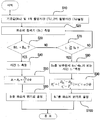
- FIG. 3 is a flowchart illustrating an image sensing method according to an embodiment of the present invention.
- an image sensing device including: an optical sensor unit configured to convert an input light reflected by a subject into an electrical signal to generate an output value; A comparison unit determining whether an output value of each of the plurality of pixels reaches a preset reference value during a preset maximum shooting time; A clock unit configured to measure the arrival time when the output value reaches the preset reference value during the preset first photographing time; And a memory unit for calculating and storing the brightness of the image by using the measured value determined by the comparison unit and the clock unit.
- FIG. 1 is a block diagram illustrating an image sensing device according to an embodiment of the present invention
- FIG. 2 is a diagram illustrating an extension of a dynamic range by an image sensing device according to an embodiment of the present invention
- FIG. 3. Is a flowchart illustrating an image sensing method according to an embodiment of the present invention.
- the time at which the brightness of the image sensing device reaches a predetermined reference value is recorded. More specifically, the time at which the brightness of each of the plurality of pixels constituting the image sensing element reaches a predetermined reference value is measured and recorded.
- the exposure time measurement error is within the quantization error range of the clock frequency, which is a reference for time measurement, to be very accurate, and the measured value is excellent in linearity in proportion to the brightness of the image. The linearity of the image is a very important factor in improving and reconstructing the image quality.
- the image sensing device according to an embodiment of the present invention, as shown in Figure 1, the optical sensor unit 100, the comparison unit 200, the clock unit 300, the image brightness calculation unit 400, and a memory unit 500.
- the optical sensor unit 100 is formed of a plurality of pixels that convert the light reflected by the subject into an electrical signal to generate an output value.
- the optical sensor unit 100 may include a micro lens, a color filter, and a substrate.
- the color filter may include at least one of a primary color filter, a complementary color filter, an infrared filter, and a low pass filter.
- the primary color filter uses red, green, and blue (RGB), which are three primary colors of light, and has excellent color reproducibility, but has a disadvantage in that the boundary part is somewhat unclear due to the sharpness of the image.
- Complementary color filters use cyan, magenta, yellow, and green (CMYK), and the image has excellent clarity, but it has a disadvantage of lack of color and shows a slightly flat color.
- the detail power is superior to the complementary color filter.
- Infrared filters are also useful for filtering out invisible light rays in those areas because of their ability to respond to light in an infrared region that is invisible to the human eye.
- the low pass filter has the advantage of removing high-frequency components such as fine branches of trees or black letters on white paper and preventing color changes.
- at least one of the above filters may be included.
- the image sensing device of the present invention relates to an image sensing device for a high dynamic range, and does not necessarily include a color filter, but may be applied to a black and white image.
- the micro lens improves light efficiency by condensing the light input to the pixel to receive an optical signal input to an area other than the pixel.
- the color filter extracts a specific color signal from the signals input from the micro lens.
- the substrate includes a photodiode and a transfer electrode, and photoelectrically converts a signal input from a color filter and then transfers the converted electrical signal to the outside.
- the optical sensor unit 100 may be a CCD (Charge Coupled Device) image sensor that moves the electrons generated by the input light to the output unit using a gate pulse.
- the present invention may be a CMOS image sensor that converts electrons generated by the input light into voltage in each pixel and then outputs them through a plurality of complementary metal oxide semiconductor (CMOS) switches.
- CMOS complementary metal oxide semiconductor
- the comparison unit 200 determines whether the output value of each of the plurality of pixels reaches a preset reference value during the preset first photographing time.
- the reference value is set by the reference value correction unit 210.
- the comparison unit 200 may be configured to include at least one capacitor for accumulating charges, and compares a voltage value (or an equivalent current value) generated by the charge accumulated in the optical sensor unit with a preset reference value. Compare.
- the preset reference value may be a saturation output value of the optical sensor unit 100, but it is preferably a value smaller than the saturation output value for accurate measurement.
- the optical sensor unit 100 accumulates charges according to the light intensity, and outputs a voltage corresponding to the accumulated charge amount to determine the brightness of the image.
- the optical sensor unit 100 cannot accumulate charges having a constant light intensity or more, and the maximum accumulation value is referred to as a saturation output value.
- the light intensity above the saturation output value is determined by the brightness of the same image.
- the saturation output value or a smaller value thereof is set as a reference value in advance, and the brightness of the actual image can be expressed according to the time to reach the reference value. . That is, the faster the time to reach the reference value, the brighter the brightness can be determined, so as to determine whether the preset reference value reaches by the comparison unit 200, the clock unit 300 to determine the arrival time Measure it.
- the clock unit 300 includes a reference clock 310 for setting the first shooting time and the second shooting time, a counter 320 for measuring the time for reaching the preset reference value, and the start of the measurement. It may include a start control unit 330 for controlling the. The smaller the reference value is, the faster the determination is possible, but too small has the disadvantage of inferior reliability. Therefore, the reference value selects a saturation output value or a predetermined value smaller than it, but is not too small.
- the clock unit 300 measures the arrival time when it is determined by the comparator 200 that the output value reaches a preset reference value during the preset first shooting time, and does not measure time when it is determined that the output value is not reached. Do not. For example, referring to FIG. 2, when the output value of the first pixel (see dotted line B1, hereinafter referred to as B1) reaches the reference value Bth, the clock unit 300 measures the arrival time t1. Similarly, when the output value of the second pixel (see dotted line B2, hereinafter referred to as B2) reaches the reference value, the clock unit 300 measures the arrival time t2. When the arrival time is measured in this way, the image brightness calculator 400 calculates the image brightness of the pixel according to Equation (1) below and stores it in the memory unit 500.
- the image brightness of the corresponding pixel is linearly calculated using the time ti at which the preset reference value is reached within the preset first photographing time T A as a parameter. See B2)
- the reference value correction unit 210 may further include a reference value correction unit 210 that generates a correction value (for example, B th ', B th ”) by lowering the preset reference value B th over time.
- a correction value for example, B th ', B th
- the reference value correction unit 210 compensates while lowering the preset reference value, but the corrected value and the output value are in an error range.
- the image brightness calculator 400 uses t 3 measured as described above and the corrected reference value B th ′.
- the brightness of the image is calculated by equation (2).
- B i ' is the brightness of the image
- B th is the preset reference value
- B th ' is the corrected reference value
- T A is the preset primary shooting time
- t i ' is the time to reach the corrected reference value
- ⁇ is a constant to be.
- the output values B1, B2, and B3 of the first to third pixels are for illustrative purposes only and do not refer to the order or number of pixels or to a specific pixel. In addition, we define "corresponds" to "matches within tolerance.”
- the image brightness of the relatively dark portion can be measured together while preventing the image of the relatively bright portion from being saturated at the maximum brightness during the second photographing time T B.
- This has the same effect as taking the shooting time of a relatively dark part longer than the shooting time of a relatively bright part, and having the same effect as opening the camera shutter until both the bright part and the dark part have the same brightness.
- This has the effect of equalizing image noise relative to image brightness.
- the brightness reference value B th , the first photographing time T A , and the second photographing time T B of the pixel (pixel) are set.
- the brightness reference value is saturated in the optical sensor unit 100. It is desirable to set it to an output value or smaller.
- the light intensity B ti of the pixel is measured (S20). That is, the light intensity of each of the plurality of pixels is measured. For example, the output values B1 to B3 of the first to third pixels are measured.
- the measured light intensity B ti reaches a preset reference value B th .
- the measured light intensity B ti is a preset reference value B th .
- the time t i at that time is measured (S40), and the brightness (B i ) of the corresponding pixel is calculated by substituting it into Equation (1) below (S50).
- S60 the brightness (B i ) of the corresponding pixel is calculated by substituting it into Equation (1) below (S50).
- B i is the brightness of the image
- B th is the preset reference value
- T B is the preset second shooting time
- t i is the time when the preset reference value is reached
- step S30 if the measured light intensity B ti does not reach the preset reference value B th , it is determined whether the first photographing time T A has elapsed (S70). If the shooting time has not elapsed, the process is repeated again from the step S20.
- the brightness of the image is calculated using Equation (2) below (S90), and the brightness of the corresponding pixel is determined (S100).
- B i ' is the brightness of the image
- B th is the preset reference value
- B th ' is the corrected reference value
- T A is the preset primary shooting time
- t i ' is the time to reach the corrected reference value
- the image brightness of the relatively dark portion can be measured together while preventing the image of the relatively bright portion from being saturated at the maximum brightness during the second photographing time T B.
- This has the same effect as taking the shooting time of a relatively dark part longer than the shooting time of a relatively bright part, and having the same effect as opening the camera shutter until both the bright part and the dark part have the same brightness.
- This has the effect of equalizing image noise relative to image brightness.
Landscapes
- Engineering & Computer Science (AREA)
- Multimedia (AREA)
- Signal Processing (AREA)
- Transforming Light Signals Into Electric Signals (AREA)
- Studio Devices (AREA)
Abstract
본 발명은 디지털 카메라 등과 같은 이미지를 촬상하는 소자에서 광의 밝기를 표현하는 동적 범위를 확장할 수 있는 이미지 센싱 소자 및 이미지 센싱 방법에 관한 것으로, 본 발명의 실시 형태에 따른 이미지 센싱 소자는, 피사체에 의해 반사되어 입력되는 광을 전기적 신호로 변환하여 출력값을 생성하는 다수의 픽셀로 이루어지는 광 센서부; 상기 다수의 픽셀 각각에 의한 출력값이 기 설정된 1차 촬영 시간 동안에 기 설정된 기준값에 도달하는 지 여부를 판단하는 비교부; 상기 비교부에 의해 상기 출력값이 기 설정된 1차 촬영 시간 동안에 기 설정된 기준값에 도달한 것으로 판단되면 그 도달 시간을 측정하는 클럭부; 및, 상기 비교부와 클럭부에 의해 판단 측정된 값을 이용하여 영상의 밝기를 산출하고 저장하는 메모리부를 포함한다. 또한, 본 발명의 실시 형태에 따른 이미지 센싱 방법은, 피사체에 의해 반사되어 입력되는 광을 전기적 신호로 변환하여 출력값을 생성하는 단계; 상기 출력값이 기 설정된 1차 촬영 시간 동안에 기 설정된 기준값에 도달하는 지 여부를 판단하는 단계; 상기 출력값이 기 설정된 1차 촬영 시간 동안에 기 설정된 기준값에 도달한 것으로 판단되면 그 도달 시간을 측정하는 단계; 및, 상기 측정된 도달 시간을 이용하여 영상의 밝기를 산출하는 단계를 포함한다.
Description
본 발명은 이미지 센싱 소자 및 이미지 센싱 방법에 관한 것으로, 보다 상세하게는 디지털 카메라 등과 같은 이미지를 촬상하는 소자에서 광의 밝기를 표현하는 동적 범위를 확장할 수 있는 이미지 센싱 소자 및 이미지 센싱 방법에 관한 것이다.
동적범위는 이미지 센서의 성능을 결정짓는 항목 중 하나로, 얼마나 약한 광신호과 강한 광신호를 영상으로 처리해 낼 수 있느냐를 나타내는 지수이다. 즉, 화소의 신호 잡음 레벨에 대한 화소의 포화 레벨(saturation level)을 의미하며, 다음의 수학식으로 주어진다.
수학식 1 
여기서, D는 이미지 센서의 동적범위를 나타내며, Noise는 신호 잡음, Saturation-level은 화소의 포화 레벨을 나타낸다.
예를 들어, 이미지 센서에서 포화시 약 20만개의 전자를 검출하고, 잡음시 약 40개의 전자가 검출되면 동적 범위는 대략 5,000이고, dB은 약 75dB 정도가 된다.
한편, 한 화면에 어두운 부분과 밝은 부분이 혼재해 있을 때 각각을 전부 구별하기 위해서는 입력광에 대한 노출 시간 조절할 수 있다. 그러나, 노출 시간 조절로 어두운 부분과 밝은 부분을 구별하는데는 한계가 있으므로 동적 범위를 넓히는 것이 요구된다.
이를 위해, 기존의 촬영 장치에서 노출시간을 바꾸어 가면서 촬영한 여러 장의 영상을 조합하여 고 동적범위 영상을 제작하는 방법이 제안되었다. 즉, 노출시간을 짧게 하여 밝은 부분의 정보를 얻고, 노출 시간을 길게 한 영상에서 어두운 영역의 정보를 얻은 후에 그 정보들을 조합하여 고 동적 범위의 영상을 획득하였다. 그러나, 이 방법은 기존의 촬상 소자를 사용한다는 장점이 있으나 노출 시간을 바꾸어 가면서 여러번 촬영을 하여야 하므로 촬영 시간이 과도하게 길어지는 문제가 있다.
이를 극복하기 위해, 인접한 화상 소자의 이득을 다르게 하여 동시에 여러 범위의 정보를 획득하는 방법이 제안되었다. 그러나 이 방법은 동적 범위를 증가시키기 위하여 공간 해상도를 저하시켜야 하는 문제가 있다.
한편, 촬영시간을 줄이기 위해 ① 한 번의 긴 촬영시간 도중에 여러번 샘플링(sampling)을 하여 다중 노출 영상 정보를 얻는 방법, ② 전자적으로 밝기에 따라서 노출 시간을 조절하는 방법, ③ 밝기가 포화될 때마다 리셋을 하고 그 횟수를 저장하는 방법 등이 제안되었다. 그러나, ① 방법에서는 촬영 시간의 개수가 제한되는 문제가 있고, ② 방법에서는 노출시간의 조절이 복잡해지는 문제가 있으며, ③ 방법에서는 회로가 복잡하고 리셋 시간 등으로 인하여 오차가 발생할 가능성이 많다는 문제가 있다.
[선행기술문헌]
[특허문헌]
(특허문헌 1) 한국공개특허 10-2008-0043635호
(특허문헌 2) 일본공개특허 2011-066795호
(특허문헌 3) 미국등록특허 7079178호
본 발명의 일 기술적 과제는 상기한 바와 같은 문제를 해결할 수 있으며 동적 범위를 확장할 수 있는 이미지 센싱 소자 및 이미지 센싱 방법을 제공하는 데 있다.
본 발명의 실시 형태에 따른 이미지 센싱 소자는,
피사체에 의해 반사되어 입력되는 광을 전기적 신호로 변환하여 출력값을 생성하는 다수의 픽셀로 이루어지는 광 센서부; 상기 다수의 픽셀 각각에 의한 출력값이 기 설정된 최대 촬영 시간 동안에 기 설정된 기준값에 도달하는 지 여부를 판단하는 비교부; 상기 비교부에 의해 상기 출력값이 기 설정된 1차 촬영 시간 동안에 기 설정된 기준값에 도달한 것으로 판단되면 그 도달 시간을 측정하는 클럭부; 및, 상기 비교부와 클럭부에 의해 판단 측정된 값을 이용하여 영상의 밝기를 산출하고 저장하는 메모리부를 포함한다.
상기 클럭부는, 기 설정된 최대 촬영 시간 동안에 상기 출력값이 상기 기 설정된 기준값에 도달하지 못하는 경우, 상기 기 설정된 기준값을 낮추어서 보정값을 생성하되, 상기 보정값과 기 설정된 기준값에 도달하지 못한 출력값이 상응할 때까지 상기 보정값을 생성하는 기준값 보정 유닛을 포함할 수 있다.
상기 광 센서부는, 상기 입력되는 광을 집속시키는 마이크로 렌즈; 상기 마이크로 렌즈로부터 입력되는 신호들 중에서 특정 색신호를 추출하는 칼라 필터; 및, 상기 추출된 색신호를 상기 전기적 신호로 변환하여 출력하는 기판을 포함할 수 있다. 여기서, 상기 칼라 필터는, 원색계 필터, 보색계 필터, 적외선 필터, 로우패스 필터 중 적어도 어느 하나를 포함할 수 있다.
한편, 상기 기 설정된 기준값은 상기 광 센서의 포화 출력값일 수 있다.
상기 비교부는 적어도 하나 이상의 커패시터를 포함하며, 상기 광 센서부에 축적된 전하에 의해 발생하는 전압값 또는 전류값을 기 설정된 기준값과 비교할 수 있다.
상기 클럭부에 의해 측정된 상기 도달 시간을 이용하여 하기의 식(1)에 의해 영상의 밝기를 산출하는 영상 밝기 산출 유닛을 포함할 수 있다.
식 (1) : Bi = Bth * TB/ti
여기서, Bi는 영상의 밝기, Bth는 기 설정된 기준값, TB는 기 설정된 2차 촬영 시간, ti는 기 설정된 기준값에 도달한 시간이다.
또한, 상기 기준값 보정 유닛에 의해 보정된 기준값과 상기 보정된 기준값에 도달하는 시간을 이용하여 하기의 식 (2)에 의해 영상의 밝기를 산출하는 영상 밝기 산출부를 포함할 수 있다.
식 (2) : Bi' = (Bth'-Bth)/(ti'-TA)*ti' + α
여기서, Bi'는 영상의 밝기, Bth는 기 설정된 기준값, Bth'는 보정된 기준값, TA는 기 설정된 1차 촬영 시간, ti’는 보정된 기준값에 도달한 시간, α는 상수이다.
상기 α는 ((Bth-Bth')/(TA-TB))*TB(여기서, TB는 기 설정된 2차 촬영 시간)일 수 있다.
또한, 본 발명의 실시 형태에 따른 이미지 센싱 방법은,
피사체에 의해 반사되어 입력되는 광을 전기적 신호로 변환하여 출력값을 생성하는 단계; 상기 출력값이 기 설정된 최대 촬영 시간 동안에 기 설정된 기준값에 도달하는지 여부를 판단하는 단계; 상기 출력값이 기 설정된 1차 촬영 시간 동안에 기 설정된 기준값에 도달한 것으로 판단되면 그 도달 시간을 측정하는 단계; 및, 상기 측정된 도달 시간을 이용하여 영상의 밝기를 산출하는 단계를 포함한다.
한편, 상기 출력값이 기 설정된 최대 촬영 시간 동안에 기 설정된 기준값에 도달하지 못한 경우, 상기 기 설정된 기준값을 낮추어서 보정값을 생성하되, 상기 보정값과 기 설정된 기준값에 도달하지 못한 출력값이 상응할 때까지 상기 보정값을 생성하는 단계를 포함할 수 있다.
상기 기 설정된 기준값은 광 센서의 포화 출력값일 수 있다.
상기 영상의 밝기를 산출하는 단계는, 하기의 식(1)에 의해 영상의 밝기를 산출할 수 있다.
식 (1) : Bi = Bth * TB/ti
여기서, Bi는 영상의 밝기, Bth는 기 설정된 기준값, TB는 기 설정된 2차 촬영 시간, ti는 기 설정된 기준값에 도달한 시간이다.
상기 출력값이 기 설정된 1차 촬영 시간 동안에 기 설정된 기준값에 도달하지 못한 경우, 상기 보정된 기준값과 상기 보정된 기준값에 도달하는 시간을 이용하여 하기의 식 (2)에 의해 영상의 밝기를 산출할 수 있다.
식 (2) : Bi' = (Bth'-Bth)/(ti'-TA)*ti' + α
여기서, Bi'는 영상의 밝기, Bth는 기 설정된 기준값, Bth'는 보정된 기준값, TA는 기 설정된 1차 촬영 시간, ti’는 보정된 기준값에 도달한 시간, α는 상수이다.
상기 α는 ((Bth-Bth')/(TA-TB))*TB(여기서, TB는 기 설정된 2차 촬영 시간)일 수 있다.
상기한 바와 같은 본 발명의 실시 형태에 의하면, 최대 촬영 시간 동안 상대적으로 밝은 부분의 영상이 최대 밝기로 포화되는 것을 방지하면서도, 상대적으로 어두운 부분의 영상 밝기를 함께 측정할 수 있게 된다. 이는 상대적으로 어두운 부분의 촬영 시간을 상대적으로 밝은 부분의 촬영 시간 보다 길게 하여 밝은 부분이나 어두운 부분이나 모두 동일한 밝기가 될 때까지 카메라 셔터를 개방한 것과 동일한 효과를 가져와서 촬상 소자의 각 위치에서의 영상 밝기에 대한 상대적인 영상 잡음을 동일하게 만드는 효과가 있다.
도 1은 본 발명의 일 실시예에 따른 이미지 센싱 소자를 도시한 블록도이고,
도 2는 본 발명의 일 실시예에 따른 이미지 센싱 소자에 의한 동적 범위의 확장을 설명하기 위한 도면이고,
도 3은 본 발명의 일 실시예에 따른 이미지 센싱 방법을 도시한 순서도이다.
상기 일 기술적 과제를 위한 본 발명의 이미지 센싱 소자는 피사체에 의해 반사되어 입력되는 광을 전기적 신호로 변환하여 출력값을 생성하는 다수의 픽셀로 이루어지는 광 센서부; 상기 다수의 픽셀 각각에 의한 출력값이 기 설정된 최대 촬영 시간 동안에 기 설정된 기준값에 도달하는 지 여부를 판단하는 비교부; 상기 비교부에 의해 상기 출력값이 기 설정된 1차 촬영 시간 동안에 기 설정된 기준값에 도달한 것으로 판단되면 그 도달 시간을 측정하는 클럭부; 및, 상기 비교부와 클럭부에 의해 판단 측정된 값을 이용하여 영상의 밝기를 산출하고 저장하는 메모리부를 포함한다.
이하, 첨부된 도면을 참조하여 본 발명의 실시예를 상세히 설명한다. 우선, 도면들 중 동일한 구성요소 또는 부품들은 가능한 한 동일한 참조부호를 나타내고 있음에 유의해야 한다. 본 발명을 설명함에 있어서 관련된 공지기능 혹은 구성에 대한 구체적인 설명은 본 발명의 요지를 모호하게 하지 않기 위해 생략한다.
도 1은 본 발명의 일 실시예에 따른 이미지 센싱 소자를 도시한 블록도이고, 도 2는 본 발명의 일 실시예에 따른 이미지 센싱 소자에 의한 동적 범위의 확장을 설명하기 위한 도면이고, 도 3은 본 발명의 일 실시예에 따른 이미지 센싱 방법을 도시한 순서도이다.
본 발명에서는 이미지 센싱 소자의 밝기가 일정한 기준치에 도달하는 시간을 기록한다. 보다 구체적으로는, 이미지 센싱 소자를 이루는 다수의 픽셀 각각의 밝기가 일정한 기준치에 도달하는 시간을 측정하여 기록한다. 본 발명에서는 노출 시간 측정 오차가 시간 측정에 기준이 되는 클럭 주파수의 양자화 오차 범위 이내가 되어 매우 정확하게 되고, 또한 측정값이 영상의 밝기에 비례하여 선형성이 우수하다. 영상의 선형성은 영상의 화질 개선과 복원에 매우 중요한 요소이다.
이를 위해, 본 발명의 일 실시예에 따른 이미지 센싱 소자는, 도 1에 도시된 바와 같이, 광 센서부(100)와, 비교부(200)와, 클럭부(300)와, 영상밝기 산출부(400)와, 메모리부(500)를 포함한다.
상기 광 센서부(100)는 피사체에 의해 반사되어 입력되는 광을 전기적 신호로 변환하여 출력값을 생성하는 다수의 픽셀로 이루어진다. 여기서, 광 센서부(100)는 구체적으로 마이크로 렌즈(micro lens), 칼라 필터(color filter), 및 기판(substrate)을 포함한다. 상기 칼라 필터는, 원색계 필터, 보색계 필터, 적외선 필터, 로우패스 필터 중 적어도 어느 하나를 포함하여 이루어질 수 있다. 원색계 필터는 빛의 삼원색인 빨강, 초록, 파랑(RGB)을 이용하는 것으로, 색상 재현력이 우수하지만 이미지의 선명성 떨어져서 경계 부분 등이 다소 불명확해 보이는 단점이 있다. 보색계 필터는 시안, 마젠터, 옐로우, 그린(CMYK)을 이용하는 것으로, 이미지의 선명성이 뛰어나나 색감이 떨어지는 단점이 있으며 다소 밋밋한 색상을 보여준다. 그러나, 세부 묘사력은 보색계 필터가 우수한 편이다. 적외선 필터는 인간의 눈으로는 보이지 않는 적외 영역의 빛에 대해서도 반응하는 특성이 있기 때문에 그러한 영역의 눈에 보이지 않는 광선을 걸러내는데 유용하다. 로우패스(low pass)필터는 나무의 세밀한 가지나, 백색 종이 위의 검은 활자 등의 공간 주파수가 높은 성분을 제거하고 색의 변질이 나타나지 않도록 하는 장점이 있다. 본 발명에서는 상기 필터들 중에서 적어도 어느 하나를 포함하여 이루어질 수 있다. 여기서, 본 발명의 이미지 센싱 소자는 고 동적 범위를 위한 이미지 센싱 소자에 관한 것으로, 반드시 칼라필터를 구비하는 것은 아니고 흑백 영상에도 적용될 수 있다.
상기 마이크로 렌즈(미도시)는 화소 이외의 영역에 입력되는 광 신호를 수신하기 위해 입력되는 광을 화소로 집광하여 광 효율을 높여 준다. 상기 칼라 필터(미도시)는 마이크로 렌즈로부터 입력되는 신호들 중에서 특정 색신호를 추출한다. 그리고, 기판(미도시)은 포토다이오드(photodiode) 및 전송 전극을 포함하며, 칼라 필터로부터 입력되는 신호를 광전변환한 후 변환된 전기적 신호를 외부로 전달한다.
여기서, 광 센서부(100)는 입력되는 광에 의해 발생한 전자를 그대로 게이트 펄스(gate pulse)를 이용해서 출력부까지 이동시키는 CCD(Charge Coupled Device)형 이미지 센서가 될 수 있다. 또는, 입력되는 광에 의해 발생한 전자를 각 화소 내에서 전압으로 변환한 후 다수의 CMOS(Complementary Metal Oxide Semiconductor) 스위치를 통해 출력하는 CMOS형 이미지 센서 등이 될 수 있다.
상기 비교부(200)는 다수의 픽셀 각각에 의한 출력값이 기 설정된 1차 촬영 시간 동안에 기 설정된 기준값에 도달하는 지 여부를 판단한다. 상기 기준값은 기준값 보정 유닛(210)에 의해 설정된다. 상기 비교부(200)는 전하 축적을 위해 적어도 하나 이상의 커패시터를 포함하도록 구성할 수 있으며, 상기 광 센서부에 축적된 전하에 의해 발생하는 전압값(또는 이와 등가인 전류값)을 기 설정된 기준값과 비교한다.
여기서, 상기 기 설정된 기준값은 상기 광 센서부(100)의 포화 출력값일 수 있으나, 정확한 측정을 위하여서 포화 출력값 보다 작은 값인 것이 바람직하다. 광 센서부(100)는 광 세기에 따라 전하를 축척하며, 축척되는 전하량에 해당하는 전압을 출력하여 영상의 밝기가 결정되도록 한다. 그러나, 광 센서부(100)는 일정한 광 세기 이상의 전하를 축적할 수 없는데, 이때 최대로 축적 가능한 값을 포화 출력값이라 한다.
종래에는 포화 출력값 이상의 광 세기에 대해서는 동일한 영상의 밝기로 결정되는데, 본 발명에서는 포화 출력값 또는 그 보다 작은 값을 기준값으로 미리 설정하고, 이 기준값에 이르는 시간에 따라 실제 영상의 밝기를 표현할 수 있도록 한다. 즉, 기준값에 이르는 시간이 빠를수록 더 밝은 밝기를 가진 것으로 판단할 수 있도록 하기 위해, 비교부(200)를 통해 기 설정된 기준값에 도달하는 지를 판단하도록 하고, 클럭부(300)가 그 도달 시간을 측정하도록 한다. 이를 위해, 상기 클럭부(300)는 1차 촬영 시간 및 2차 촬영 시간을 설정하기 위한 기준 클럭(310)과, 기 설정된 기준값에 도달하는 시간을 측정하기 위한 카운터(320)와, 측정의 시작을 제어하기 위한 시작 제어 유닛(330)을 포함할 수 있다. 기준값이 작을수록 신속한 판단이 가능하나, 지나치게 작으면 판단의 신뢰성이 떨어지는 단점이 있다. 따라서, 기준값은 포화 출력값 또는 그 보다 작은 소정의 값을 선택하되, 지나치게 작은 값이 되지 않도록 한다.
상기 클럭부(300)는 상기 비교부(200)에 의해 상기 출력값이 기 설정된 1차 촬영 시간 동안에 기 설정된 기준값에 도달한 것으로 판단되면 그 도달 시간을 측정하며, 부도달로 판단되면 시간을 측정하지 않는다. 예를 들어, 도 2를 참조하면, 제1 화소의 출력값(점선 B1 참조, 이하 B1이라 함)이 기준값(Bth)에 도달하면 클럭부(300)가 그 도달 시간 t1을 측정한다. 마찬가지로 제2 화소의 출력값(점선 B2 참조, 이하 B2라 함)이 기준값에 도달하면 클럭부(300)가 그 도달 시간 t2을 측정한다. 이렇게 도달 시간이 측정되면, 영상 밝기 산출부(400)에서 해당 화소의 영상 밝기를 하기의 식(1)에 따라 산출하고, 이를 메모리부(500)에 저장한다.
식 (1) : Bi = Bth * TB/ti
(여기서, Bi는 영상의 밝기, Bth는 기 설정된 기준값, TB는 기 설정된 2차 촬영 시간, ti는 기 설정된 기준값에 도달한 시간)
즉, 도 2에 도시된 바와 같이, 기 설정된 1차 촬영 시간 TA 내에 기 설정된 기준값에 도달한 시간 ti를 매개 변수로 하여 해당 화소의 영상 밝기를 선형적으로 산출한다.(도 2의 B1, B2 참조)
그러나, 제3 화소의 출력값(점선 B3 참조, 이하 B3라 함)는 기 설정된 1차 촬영 시간 내에 기준값에 도달하지 못하여 도달 시간이 측정되지 않는다. 따라서, ti를 정할 수 없어서 식 (1)에 의해 해당 화소의 밝기를 산출할 수 없게 된다. 이를 보완하기 위해 기 설정된 기준값(Bth)을 시간 경과에 따라 낮추어서 보정값(예를 들어, Bth', Bth")을 생성하는 기준값 보정 유닛(210)을 더 포함한다. 비교부(200)에 의해 제3 화소의 출력값(B3)가 기 설정된 기준값(Bth)에 도달하지 못한 것으로 판단되면, 기준값 보정 유닛(210)은 기 설정된 기준값을 낮추어가면서 보정하되, 보정된 값과 출력값이 오차 범위 내에서 일치할 때까지 보정을 진행한다. 이에 대해, 도 3을 참조하여 설명하면, 기 설정된 1차 촬영 시간(TA) 동안 제3 화소의 출력값은 기 설정된 기준값(Bth)에 도달하지 못하였으므로, 도달 시간을 측정하지 못한다. 따라서, 식 (1)에 의한 영상 밝기를 산출할 수 없으므로, 기 설정된 기준값(Bth)을 보다 작은 값Bth_1로 보정한다. 제3 화소의 출력값(B3)은 보정된 기준값 Bth_1도 도달하지 못하고 있으므로, 보정된 기준값 Bth'를 보다 작은 값으로 재보정한다. 이 경우 Bth 를 시간에 따라 감소하는 함수로 간주하여 Bth(t)로 표시할 수 있다. 이렇게 보정 과정을 계속 진행하여 제3 화소의 출력값이 Bth(t)로 이루어진 직선과 만나는 지점의 시간(t3)를 측정한다. 영상 밝기 산출부(400)는 이렇게 측정된 t3와 보정된 기준값 Bth'를 이용하여 하기의 식 (2)에 의해 영상의 밝기를 산출한다.
식 (2) : Bi' = (Bth'-Bth)/(ti'-TA)*ti' + α
여기서, Bi'는 영상의 밝기, Bth는 기 설정된 기준값, Bth'는 보정된 기준값, TA는 기 설정된 1차 촬영 시간, ti’는 보정된 기준값에 도달한 시간, α는 상수이다.
도 3을 참조하면 상기 α를 산출할 수 있는데, 2차 촬영 시간(TB)에서 Bth가 0이 되므로 0 = (Bth'-Bth)/(TB-TA)*TB + α 으로부터 α는 ((Bth-Bth')/(TA-TB))*TB임을 구할 수 있다. 상기에서 제1 내지 제3 화소의 출력값(B1, B2, B3)은 설명을 위한 예시일 뿐, 화소의 순서나 개수 또는 특정 화소를 지칭하는 것은 아니다. 또한, “오차 범위 내에서 일치”한다는 것을 “상응한다”로 정의한다.
이와 같이 함으로써, 2차 촬영 시간(TB) 동안 상대적으로 밝은 부분의 영상이 최대 밝기로 포화되는 것을 방지하면서도, 상대적으로 어두운 부분의 영상 밝기를 함께 측정할 수 있게 된다. 이는 상대적으로 어두운 부분의 촬영 시간을 상대적으로 밝은 부분의 촬영 시간 보다 길게 하여 밝은 부분이나 어두운 부분이나 모두 동일한 밝기가 될 때까지 카메라 셔터를 개방한 것과 동일한 효과를 가져와서 촬상 소자의 각 위치에서의 영상 밝기에 대한 상대적인 영상 잡음을 동일하게 만드는 효과가 있다.
다음으로, 도 3을 참조하여 본 발명의 일 실시예에 따른 이미지 센싱 방법을 설명한다.
먼저, 화소(픽셀)의 밝기 기준값(Bth) 및 1차 촬영 시간(TA), 2차 촬영 시간(TB)을 설정한다.(S10) 상기 밝기 기준값은 광 센서부(100)의 포화 출력값 또는 그 보다 작은 값으로 설정되는 것이 바람직하다.
그 다음, 화소의 광 세기(Bti)를 측정한다.(S20) 즉, 다수개의 화소 각각에 대한 광 세기를 측정한다. 예를 들어, 상기 제1 내지 제3 화소의 출력값(B1 ~ B3)를 측정한다.
그 다음, 상기 측정된 광 세기(Bti)가 미리 설정된 기준값(Bth)에 도달하는 지 여부를 판단한다.(S30) 이때, 측정된 광 세기(Bti)가 미리 설정된 기준값(Bth)에 도달하면, 그 때의 시간 ti를 측정하고(S40), 이를 하기의 식 (1)에 대입하여 해당 화소의 밝기(Bi)를 산출한다.(S50) 그리고, 이를 해당 화소의 밝기로 결정한다.(S60)
식 (1) : Bi = Bth * TB/ti
(여기서, Bi는 영상의 밝기, Bth는 기 설정된 기준값, TB는 기 설정된 2차 촬용 시간, ti는 기 설정된 기준값에 도달한 시간)
상기 S30 단계에서의 판단 결과, 측정된 광 세기(Bti)가 미리 설정된 기준값(Bth)에 도달하지 못하면, 1차 촬영 시간(TA)의 경과 여부를 판단한다.(S70) 아직 1차 촬영 시간이 경과되지 않았다면 상기 S20 단계부터 다시 반복한다.
1차 촬영 시간(TA)이 경과하였는데 측정된 광 세기(Bti)가 미리 설정된 기준값(Bth)에 도달하지 못하면, Bth를 낮추면서 Bth' = Bti 가 되는 ti를 측정한다.(S80)
이렇게 측정된 ti와 보정된 기준값 Bth'를 이용하여 하기의 식 (2)에 의해 영상의 밝기를 산출한다.(S90) 그리고, 이를 해당 화소의 밝기로 결정한다.(S100)
식 (2) : Bi' = (Bth'-Bth)/(ti'-TA)*ti' + α
여기서, Bi'는 영상의 밝기, Bth는 기 설정된 기준값, Bth'는 보정된 기준값, TA는 기 설정된 1차 촬영 시간, ti’는 보정된 기준값에 도달한 시간, α는 상수이다. 도 3을 참조하면 상기 α를 산출할 수 있는데, 2차 촬영 시간(TB)에서 Bth가 0이 되므로 0 = (Bth'-Bth)/(TB-TA)*TB + α 으로부터 α는 ((Bth-Bth')/(TA-TB))*TB임을 구할 수 있다.
이와 같이 함으로써, 2차 촬영 시간(TB) 동안 상대적으로 밝은 부분의 영상이 최대 밝기로 포화되는 것을 방지하면서도, 상대적으로 어두운 부분의 영상 밝기를 함께 측정할 수 있게 된다. 이는 상대적으로 어두운 부분의 촬영 시간을 상대적으로 밝은 부분의 촬영 시간 보다 길게 하여 밝은 부분이나 어두운 부분이나 모두 동일한 밝기가 될 때까지 카메라 셔터를 개방한 것과 동일한 효과를 가져와서 촬상 소자의 각 위치에서의 영상 밝기에 대한 상대적인 영상 잡음을 동일하게 만드는 효과가 있다.
이상과 같이 본 발명에 따른 이미지 센싱 소자 및 이미지 센싱 방법을 예시한 도면을 참조로 하여 설명하였으나, 본 명세서에 개시된 실시예와 도면에 의해 본 발명이 한정되는 것은 아니며, 본 발명의 기술사상 범위 내에서 당업자에 의해 다양한 변형이 이루어질 수 있음은 물론이다.
Claims (15)
- 피사체에 의해 반사되어 입력되는 광을 전기적 신호로 변환하여 출력값을 생성하는 다수의 픽셀로 이루어지는 광 센서부;상기 다수의 픽셀 각각에 의한 출력값이 기 설정된 최대 촬영 시간 동안에 기 설정된 기준값에 도달하는 지 여부를 판단하는 비교부;상기 비교부에 의해 상기 출력값이 기 설정된 1차 촬영 시간 동안에 기 설정된 기준값에 도달한 것으로 판단되면 그 도달 시간을 측정하는 클럭부; 및,상기 비교부와 클럭부에 의해 판단 측정된 값을 이용하여 영상의 밝기를 산출하고 저장하는 메모리부를 포함하는 이미지 센싱 소자.
- 청구항 1에 있어서,상기 클럭부는, 기 설정된 최대 촬영 시간 동안에 상기 출력값이 상기 기 설정된 기준값에 도달하지 못하는 경우, 상기 기 설정된 기준값을 낮추어서 보정값을 생성하되, 상기 보정값과 기 설정된 기준값에 도달하지 못한 출력값이 상응할 때까지 상기 보정값을 생성하는 기준값 보정 유닛을 포함하는 이미지 센싱 소자.
- 청구항 1에 있어서,상기 광 센서부는,상기 입력되는 광을 집속시키는 마이크로 렌즈;상기 마이크로 렌즈로부터 입력되는 신호들 중에서 특정 색신호를 추출하는 칼라 필터; 및,상기 추출된 색신호를 상기 전기적 신호로 변환하여 출력하는 기판을 포함하는 이미지 센싱 소자.
- 청구항 3에 있어서,상기 칼라 필터는, 원색계 필터, 보색계 필터, 적외선 필터, 로우패스 필터 중 적어도 어느 하나를 포함하는 이미지 센싱 소자.
- 청구항 1 내지 청구항 3 중 어느 한 항에 있어서,상기 기 설정된 기준값은 상기 광 센서부의 포화 출력값 이하인 이미지 센싱 소자.
- 청구항 1 내지 청구항 3 중 어느 한 항에 있어서,상기 비교부는 적어도 하나 이상의 커패시터를 포함하며, 상기 광 센서부에 축적된 전하에 의해 발생하는 전압값 또는 전류값을 기 설정된 기준값과 비교하는 이미지 센싱 소자.
- 청구항 1 내지 청구항 3 중 어느 한 항에 있어서,상기 클럭부에 의해 측정된 상기 도달 시간을 이용하여 하기의 식(1)에 의해 영상의 밝기를 산출하는 영상 밝기 산출부를 포함하는 이미지 센싱 소자식 (1) : Bi = Bth * TB/ti(여기서, Bi는 영상의 밝기, Bth는 기 설정된 기준값, TB는 기 설정된 2차 촬영 시간, ti는 기 설정된 기준값에 도달한 시간).
- 상기 클럭부에 의해 측정된 상기 도달 시간을 이용하여 하기의 식(1)에 의해 청구항 2에 있어서,상기 기준값 보정 유닛에 의해 보정된 기준값과 상기 보정된 기준값에 도달하는 시간을 이용하여 하기의 식 (2)에 의해 영상의 밝기를 산출하는 영상 밝기 산출부를 포함하는 이미지 센싱 소자식 (2) : Bi' = (Bth'-Bth)/(ti'-TA)*ti' + α(여기서, Bi'는 영상의 밝기, Bth는 기 설정된 기준값, Bth'는 보정된 기준값, TA는 기 설정된 1차 촬영 시간, ti'는 보정된 기준값에 도달한 시간, α는 상수).
- 청구항 8에 있어서,상기 α는 ((Bth-Bth')/(TA-TB))*TB (여기서, TB는 기 설정된 2차 촬영 시간)인 이미지 센싱 소자.
- 피사체에 의해 반사되어 입력되는 광을 전기적 신호로 변환하여 출력값을 생성하는 단계;상기 출력값이 기 설정된 최대 촬영 시간 동안에 기 설정된 기준값에 도달하는 지 여부를 판단하는 단계;상기 출력값이 기 설정된 1차 촬영 시간 동안에 기 설정된 기준값에 도달한 것으로 판단되면 그 도달 시간을 측정하는 단계; 및,상기 측정된 도달 시간을 이용하여 영상의 밝기를 산출하는 단계를 포함하는 이미지 센싱 방법.
- 청구항 10에 있어서,상기 출력값이 기 설정된 최대 촬영 시간 동안에 기 설정된 기준값에 도달하지 못한 경우, 상기 기 설정된 기준값을 낮추어서 보정값을 생성하되, 상기 보정값과 기 설정된 기준값에 도달하지 못한 출력값이 상응할 때까지 상기 보정값을 생성하는 단계를 포함하는 이미지 센싱 방법.
- 청구항 10에 있어서,상기 기 설정된 기준값은 광 센서의 포화 출력값 이하인 이미지 센싱 방법.
- 청구항 10 내지 청구항 12 중 어느 한 항에 있어서,상기 영상의 밝기를 산출하는 단계는, 하기의 식 (1)에 의해 영상의 밝기를 산출하는 이미지 센싱 방법식 (1) : Bi = Bth * TB/ti(여기서, Bi는 영상의 밝기, Bth는 기 설정된 기준값, TB는 기 설정된 2차 촬영 시간, ti는 기 설정된 기준값에 도달한 시간).
- 청구항 11에 있어서,상기 보정된 기준값과 상기 보정된 기준값에 도달하는 시간을 이용하여 하기의 식 (2)에 의해 영상의 밝기를 산출하는 이미지 센싱 방법식 (2) : Bi' = (Bth'-Bth)/(ti'-TA)*ti' + α(여기서, Bi'는 영상의 밝기, Bth는 기 설정된 기준값, Bth'는 보정된 기준값, TA는 기 설정된 1차 촬영 시간, ti'는 보정된 기준값에 도달한 시간, α는 상수).
- 청구항 14에 있어서,상기 α는 ((Bth-Bth')/(TA-TB))*TB (여기서, TB는 기 설정된 2차 촬영 시간)인 이미지 센싱 방법.
Applications Claiming Priority (2)
| Application Number | Priority Date | Filing Date | Title |
|---|---|---|---|
| KR10-2011-0146583 | 2011-12-29 | ||
| KR1020110146583A KR101313968B1 (ko) | 2011-12-29 | 2011-12-29 | 이미지 센싱 소자 및 이미지 센싱 방법 |
Publications (1)
| Publication Number | Publication Date |
|---|---|
| WO2013100328A1 true WO2013100328A1 (ko) | 2013-07-04 |
Family
ID=48697754
Family Applications (1)
| Application Number | Title | Priority Date | Filing Date |
|---|---|---|---|
| PCT/KR2012/007914 Ceased WO2013100328A1 (ko) | 2011-12-29 | 2012-09-28 | 이미지 센싱 소자 및 이미지 센싱 방법 |
Country Status (2)
| Country | Link |
|---|---|
| KR (1) | KR101313968B1 (ko) |
| WO (1) | WO2013100328A1 (ko) |
Families Citing this family (1)
| Publication number | Priority date | Publication date | Assignee | Title |
|---|---|---|---|---|
| KR102611704B1 (ko) * | 2021-07-14 | 2023-12-07 | 연세대학교 산학협력단 | 이미지 센서 및 이미지 획득 방법 |
Citations (3)
| Publication number | Priority date | Publication date | Assignee | Title |
|---|---|---|---|---|
| KR100834763B1 (ko) * | 2006-11-14 | 2008-06-05 | 삼성전자주식회사 | 동적 촬영 대역의 확장을 위한 이미지 센서 및 화소에수광된 광량을 측정하는 방법 |
| KR100873279B1 (ko) * | 2006-10-11 | 2008-12-11 | 아바고 테크놀로지스 제너럴 아이피 (싱가포르) 피티이 리미티드 | 이미징 디바이스의 자동 이득 제어를 제공하는 시스템 및방법 |
| JP2011066795A (ja) * | 2009-09-18 | 2011-03-31 | Fujifilm Corp | 撮像装置及び撮像制御方法 |
-
2011
- 2011-12-29 KR KR1020110146583A patent/KR101313968B1/ko not_active Expired - Fee Related
-
2012
- 2012-09-28 WO PCT/KR2012/007914 patent/WO2013100328A1/ko not_active Ceased
Patent Citations (3)
| Publication number | Priority date | Publication date | Assignee | Title |
|---|---|---|---|---|
| KR100873279B1 (ko) * | 2006-10-11 | 2008-12-11 | 아바고 테크놀로지스 제너럴 아이피 (싱가포르) 피티이 리미티드 | 이미징 디바이스의 자동 이득 제어를 제공하는 시스템 및방법 |
| KR100834763B1 (ko) * | 2006-11-14 | 2008-06-05 | 삼성전자주식회사 | 동적 촬영 대역의 확장을 위한 이미지 센서 및 화소에수광된 광량을 측정하는 방법 |
| JP2011066795A (ja) * | 2009-09-18 | 2011-03-31 | Fujifilm Corp | 撮像装置及び撮像制御方法 |
Also Published As
| Publication number | Publication date |
|---|---|
| KR101313968B1 (ko) | 2013-10-01 |
| KR20130077718A (ko) | 2013-07-09 |
Similar Documents
| Publication | Publication Date | Title |
|---|---|---|
| US9860438B2 (en) | Image sensor and electronic apparatus | |
| US8018509B2 (en) | Image input processing apparatus and method | |
| US8890981B2 (en) | Method and apparatus for eliminating crosstalk amount included in an output signal | |
| CN100370811C (zh) | 数字静态照相装置、摄像装置和信息终端装置及其活点量计算方法 | |
| KR100900485B1 (ko) | 구조가 개선된 디지털 카메라용 이미지 센싱 수단 및 이를채용한 디지털 카메라 | |
| CN101374196A (zh) | 摄像系统及图像处理程序 | |
| US6831687B1 (en) | Digital camera and image signal processing apparatus | |
| JP2003259389A (ja) | 撮像装置 | |
| JP2007259237A (ja) | 撮像装置および撮像方法 | |
| JP4649734B2 (ja) | 映像信号処理装置および映像信号処理プログラムを記録した記録媒体 | |
| WO2013100328A1 (ko) | 이미지 센싱 소자 및 이미지 센싱 방법 | |
| JPH08107560A (ja) | 画像入力装置 | |
| JP2013219452A (ja) | 色信号処理回路、色信号処理方法、色再現評価方法、撮像装置、電子機器、及び、試験装置 | |
| KR20010076835A (ko) | 디지털 카메라의 자동 화이트 밸런스 장치 및 방법 | |
| JP3897370B2 (ja) | 撮像装置 | |
| CN201352825Y (zh) | 数码成像测控装置及采用该测控装置的数码成像系统 | |
| JP2002185976A (ja) | 映像信号処理装置および映像信号処理プログラムを記録した記録媒体 | |
| JP5267290B2 (ja) | 画像処理装置、画像処理方法および画像処理プログラム | |
| WO2013183886A1 (en) | Camera system with multi-spectral filter array and image processing method thereof | |
| JP2003309857A (ja) | 画像処理装置および方法、記録媒体、並びにプログラム | |
| KR20050006424A (ko) | 색신호 처리방법 및 그 방법을 사용하는 촬상장치 | |
| JP3310973B2 (ja) | 撮像素子の露出制御装置 | |
| JPH07131815A (ja) | ビデオカメラ | |
| KR100727839B1 (ko) | 고체촬상소자를 사용하여 색 제어 동작을 수행하는 디지털카메라 시스템 | |
| JPS63290480A (ja) | 撮像装置 |
Legal Events
| Date | Code | Title | Description |
|---|---|---|---|
| 121 | Ep: the epo has been informed by wipo that ep was designated in this application |
Ref document number: 12861802 Country of ref document: EP Kind code of ref document: A1 |
|
| NENP | Non-entry into the national phase |
Ref country code: DE |
|
| 122 | Ep: pct application non-entry in european phase |
Ref document number: 12861802 Country of ref document: EP Kind code of ref document: A1 |