WO2013094074A1 - 鞍乗型車両 - Google Patents
鞍乗型車両 Download PDFInfo
- Publication number
- WO2013094074A1 WO2013094074A1 PCT/JP2011/079943 JP2011079943W WO2013094074A1 WO 2013094074 A1 WO2013094074 A1 WO 2013094074A1 JP 2011079943 W JP2011079943 W JP 2011079943W WO 2013094074 A1 WO2013094074 A1 WO 2013094074A1
- Authority
- WO
- WIPO (PCT)
- Prior art keywords
- fuel tank
- gaseous fuel
- vehicle
- straddle
- type vehicle
- Prior art date
- Legal status (The legal status is an assumption and is not a legal conclusion. Google has not performed a legal analysis and makes no representation as to the accuracy of the status listed.)
- Ceased
Links
Images



Classifications
-
- B—PERFORMING OPERATIONS; TRANSPORTING
- B62—LAND VEHICLES FOR TRAVELLING OTHERWISE THAN ON RAILS
- B62J—CYCLE SADDLES OR SEATS; AUXILIARY DEVICES OR ACCESSORIES SPECIALLY ADAPTED TO CYCLES AND NOT OTHERWISE PROVIDED FOR, e.g. ARTICLE CARRIERS OR CYCLE PROTECTORS
- B62J35/00—Fuel tanks specially adapted for motorcycles or engine-assisted cycles; Arrangements thereof
-
- B—PERFORMING OPERATIONS; TRANSPORTING
- B62—LAND VEHICLES FOR TRAVELLING OTHERWISE THAN ON RAILS
- B62K—CYCLES; CYCLE FRAMES; CYCLE STEERING DEVICES; RIDER-OPERATED TERMINAL CONTROLS SPECIALLY ADAPTED FOR CYCLES; CYCLE AXLE SUSPENSIONS; CYCLE SIDECARS, FORECARS, OR THE LIKE
- B62K2202/00—Motorised scooters
Definitions
- the present invention relates to a saddle riding type vehicle.
- underbone type straddle type vehicle such as a scooter or a moped type motorcycle has been proposed that uses gaseous fuel as a power source.
- Cited Document 1 shows a scooter type vehicle using gas fuel as a power source.
- two gas cylinders filled with gas fuel are arranged below the step board.
- the gaseous fuel tank since gaseous fuel becomes high pressure when the fuel tank is filled, the gaseous fuel tank must be a pressure vessel, and the shape thereof is a cylinder having a cylindrical side surface. Therefore, in order to secure a sufficient volume of the gaseous fuel tank, its diameter must be increased.
- the space under the step board in the underbone saddle riding type vehicle is limited, such a large gaseous fuel is required. Tanks cannot be placed. Therefore, when the gaseous fuel tank is divided into a plurality of pieces as in the above-mentioned Patent Document 1, although the gaseous fuel tank can be surely arranged in the space under the step board, the cost of the gaseous fuel tank increases, and the capacity still remains. Run short.
- the present invention has been made in view of such a viewpoint, and an object of the present invention is to place a large gaseous fuel tank in a space under a step board in an underbone straddle-type vehicle and which has a good occupant. It is to be able to take a posture.
- a saddle a step board that is disposed in front of and below the saddle and includes a foot space that is an area on which a passenger's foot is placed, and a gaseous fuel tank having a cylindrical side surface, the gaseous fuel tank Is arranged on the vehicle central axis in a plan view, and is arranged on the vehicle central axis, and in a side view, the axis is inclined so that the front side of the vehicle is down, and a part of the gaseous fuel tank
- a straddle-type vehicle wherein a certain protruding portion is disposed above a plane including the foot space, and the foot space is provided on a side of the protruding portion.
- straddle-type vehicle according to any one of (1) to (4), wherein a vehicle width direction dimension of the protruding portion is narrower on a vehicle front side than on a vehicle rear side.
- a ground clearance of the straddle-type vehicle at a lower portion of the gaseous fuel tank is low on a vehicle front side and high on a vehicle rear side.
- a prime mover further disposed behind the gaseous fuel tank, and a reduced pressure disposed behind the gaseous fuel tank and above the prime mover.
- a straddle-type vehicle having a regulator.
- the gaseous fuel tank includes a gaseous fuel outlet at a position eccentric to the upper side of the rear end face.
- the gas fuel tank is sandwiched from the left and right, and a pair of side frames coupled above the gas fuel tank, and both ends of the pair of side frames.
- a first reinforcing frame that is fixed to the front side end surface of the gaseous fuel tank, and a second reinforcing frame that has both ends fixed to the pair of side frames and supports the lower side surface of the gaseous fuel tank;
- a straddle-type vehicle having a frame with
- a large gaseous fuel tank is disposed in the space under the step board, and the passenger has a good riding posture. Can be taken.
- a foot space on the step board can be secured.
- the ramp breakover angle of the saddle riding type vehicle can be further increased.
- the decompression regulator is disposed in the dead space, and the straddle-type vehicle can be made compact.
- the pipe length of the pipe connecting the gaseous fuel tank and the pressure reducing regulator can be shortened.
- the gas fuel tank is protected by the frame, and at the same time, the gas fuel tank is disposed at a position close to the front wheel, and the straddle-type vehicle can be made compact.
- FIG. 1 is a side view showing a structure of a saddle riding type vehicle 1 according to an embodiment of the present invention.
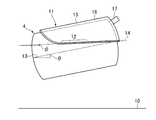
- 3 is a side view showing the positional relationship between the gaseous fuel tank 4 and the step board 11.
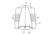
- FIG. 3 is a plan view showing the positional relationship between the gaseous fuel tank 4 and the step board 11.
- FIG. 4 is a side view of the frame 3.
- FIG. 3 is a front view of a frame 3.
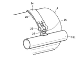
- FIG. FIG. 4 is a partial perspective view showing a state in which a gaseous fuel tank 4 is fixed by a fixing band 24.
- FIG. 1 is a side view showing the structure of a saddle riding type vehicle 1 according to an embodiment of the present invention.
- the saddle riding type vehicle 1 is shown as a so-called scooter type motorcycle, but the present invention is intended for an underbone type saddle riding type vehicle, and a scooter is an example.
- the saddle riding type vehicle refers to a motor vehicle having a saddle on which an occupant sits, and is referred to as a motorcycle, a motor tricycle, an ATV (All Terrain Vehicle), or a three-wheel or four-wheel buggy or snowmobile. including.
- the underbone saddle-type vehicle is a saddle-type vehicle and has a wide space in front of the saddle, and when the occupant is seated, the occupant's feet are in front of the saddle and It shall refer to the type that can be placed on the step board provided below.
- the scooter described in the present embodiment or a so-called moped type corresponds to an underbone straddle-type vehicle.
- FIG. 1 the outer shape of the body 2 of the saddle-ride type vehicle 1 is shown by a broken line, and a swing including each member arranged therein, that is, a frame 3, a gas fuel tank 4, a pressure reducing regulator 5, and a prime mover 6.
- the positional relationship of the unit 7 is clearly shown.
- the front wheel 8 and the rear wheel 9 are shown by their outer shapes.
- the position of the ground 10 on which the saddle riding type vehicle 1 is placed is shown as a horizontal plane.
- the gaseous fuel tank 4 is a tank for storing gaseous fuel whose volume is reduced or liquefied by being compressed, and is a pressure vessel for withstanding the high pressure of the gaseous fuel. Therefore, the gaseous fuel tank 4 has a cylindrical shape having a cylindrical side surface, and the surfaces corresponding to the top surface and the bottom surface of the cylinder are rounded and are smoothly connected to the side cylinder. In the illustrated example, the surfaces corresponding to the top and bottom surfaces of the gaseous fuel tank 4 are convex toward the outside. However, the surface may be reversed to be concave.
- gaseous fuel is not particularly limited as long as it is a gaseous fuel at normal temperature and normal pressure, and any gas fuel may be used, and it does not matter whether liquefaction occurs under high pressure.
- gaseous fuel include hydrogen, methane gas, and propane gas.
- the decompression regulator 5 is a regulator for decompressing the high-pressure gaseous fuel sent from the gaseous fuel tank 4 and sending it to the prime mover 6.
- the gaseous fuel tank 4 and the decompression regulator 5 are both fixed to the frame 3 in this embodiment.
- the swing unit 7 is rotatably attached to the frame 3 and a rear wheel 9 is attached.
- the prime mover 6 is an internal combustion engine, parts such as a transmission, a clutch, an exhaust manifold, and a muffler are attached to the swing unit 7 in addition to the prime mover 6.
- the prime mover 6 is a four-stroke engine that is a general internal combustion engine in the present embodiment, but is not limited thereto, and may be, for example, a combination of a fuel cell and an electric motor. .
- the electric motor may be arranged so as to be coupled to the axle of the rear wheel 9 via a transmission as in the case of the internal combustion engine, or the output of the rear wheel axle and the electric motor like a so-called in-wheel motor. You may arrange
- FIG. 2 is a side view showing the positional relationship between the gaseous fuel tank 4 and the step board 11.
- FIG. 3 is a plan view showing the positional relationship between the gaseous fuel tank 4 and the step board 11.
- parts other than the gaseous fuel tank 4 and the step board 11 are not shown for easy understanding.
- the part which cannot be seen behind the step board 11 among the gaseous fuel tank 4 was shown with the broken line.
- the step board 11 is a part of the body 2 shown in FIG. 1 and is provided in front of and below the saddle, and is formed with a foot space 12 that is a region where an occupant puts his / her foot when seated. Point to.
- step board 11 only the region that can be regarded as the step board 11 is cut out and shown as an independent member.
- the step board 11 does not necessarily have an independent structure, and is integrated with other parts of the body 2. It may be connected. Alternatively, the step board 11 itself may be further finely divided.
- the foot space 12 provided on the upper surface of the step board 11 is provided with non-slip irregularities, and in FIG. It is shown. Of course, the presence or absence of this anti-slip is arbitrary.
- the gas fuel tank 4 has a central axis 13 (shown by a one-dot chain line) in the plan view as viewed in a plan view, and as shown in FIG. 2, in a side view.
- the central axis 13 is inclined so that the front side of the vehicle is down.
- the inclination angle of the central axis 13 with respect to the ground 10 is shown as ⁇ .
- a part of the gaseous fuel tank 4 protrudes above the surface of the step board 11 where the foot space 12 is provided.
- the portion of the gaseous fuel tank 4 positioned above the plane 14 (indicated by a two-dot chain line) including the foot space 12 will be referred to as a protrusion 15.
- the step board 11 has a protruding cover portion 16 that swells upward in accordance with the position of the protruding portion 15 in order to cover the protruding portion 15.
- the plane 14 is substantially parallel to the ground 10 or slightly inclined. In the present embodiment, the plane 14 is inclined with respect to the ground 10 so that the front side of the vehicle is down, and the inclination angle is indicated by ⁇ .
- the central axis 13 of the gaseous fuel tank 4 is arranged so as to coincide with the vehicle central axis, that is, the central axis in the vehicle longitudinal direction of the saddle riding type vehicle 1 in plan view.
- the protruding cover 16 of the board 11 appears at the center of the step board 11 in the vehicle width direction. Therefore, the foot space 12 is provided on the side of the protruding cover 16, that is, on the side of the protruding portion 15.
- the central axis 13 of the gaseous fuel tank 4 and the vehicle central axis do not have to coincide exactly, and the gaseous fuel tank 4 is disposed on the vehicle central axis, that is, the vehicle central axis is the gaseous fuel tank 4.
- the center axis line 13 and the vehicle center axis coincide as much as possible from the viewpoint of weight and the left and right balance of the foot space 12.
- the planar shape of the projecting portion 15 is the vehicle front side width (vehicle width direction) as seen in the projecting covering portion 16 of FIG. Is substantially trapezoidal with a narrow width and a wide rear side of the vehicle.
- the width of the foot space 12 is opposite to that of the projecting cover portion 16, the width on the front side of the vehicle is wide and the width on the rear side of the vehicle is narrow.
- variety of the vehicle front side of the foot space 12 becomes wide, when a passenger
- a human foot has the largest width near the base of the finger and becomes narrower toward the heel, so there is no particular problem even if the width of the foot space 12 on the rear side of the vehicle is narrow.
- the width of the foot space 12 does not necessarily match the width of the entire step board 11.
- the overall width of the step board 11 may be constant or may change gradually, and its shape is determined as a part of the design of the saddle riding type vehicle 1 as a whole.
- the central axis 13 of the gaseous fuel tank 4 is the same height as the plane 14 including the foot space 12 in the entire length of the gaseous fuel tank 4, or It is preferable to be located below. That is, the gaseous fuel tank 4 is arranged such that a portion of the central axis line 13 shown in FIG. 2 that is included inside the gaseous fuel tank 4 has a height equal to or lower than the plane 14 in the side view as shown in the figure. Is done. With such an arrangement, the protruding amount of the protruding portion 15 from the flat surface 14 is suppressed, and the width of the foot space 12 is effectively ensured.
- the ramp break over angle ⁇ in the saddle riding type vehicle 1 shown in the figure will be considered.
- the ramp break over angle ⁇ is a value indicating the running performance on rough terrain of the vehicle, and in the side view, the ground point A of the front wheel 8 and the ground point B of the rear wheel 9 and the center of the ground point A and the ground point B are shown. This is the angle formed by the line segment connecting the lowest point C of the vehicle at the position and the ground 10, and the greater the ramp breakover angle ⁇ , the higher the running performance on rough terrain. Also, under the line segments AC and BC, members that come in contact with obstacles on the road must not be placed.
- the gaseous fuel tank 4 has a cylindrical shape, and its central axis 13 is inclined so that the front side of the vehicle faces downward. Therefore, the ground clearance below the gaseous fuel tank 4 is low on the front side of the vehicle and high on the rear side of the vehicle. And since the shape of the body 2 is also adapted to the arrangement of the gaseous fuel tank 4, the ground height of the saddle riding type vehicle 1 at the lower part of the gaseous fuel tank 4 is low on the vehicle front side and high on the vehicle rear side. It will be a thing. With this structure, even if the gaseous fuel tank 4 is disposed on the lower side of the step board 11 (see FIG. 2), the gaseous fuel tank 4 or the body 2 does not interfere with the illustrated line segment AC, and the lamp breakover angle ⁇ is increased. It will be big.
- the gaseous fuel in order to use the high-pressure gaseous fuel filled in the gaseous fuel tank 4 in the prime mover 6, the gaseous fuel must be decompressed to a pressure suitable for use in the prime mover 6. Therefore, it is necessary to interpose a pressure reducing regulator 5 in the middle of the piping connecting the gaseous fuel tank 4 and the prime mover 6, but the pressure reducing regulator 5 used for such applications needs to have a certain size due to functional limitations. , Its placement becomes a problem.
- the decompression regulator 5 is arranged at a position behind the gaseous fuel tank 4 and above the prime mover 6. As is clear from the figure, this position is below the front part of the saddle, and is a position that becomes a dead space on the back side of the knee when the occupant is seated. Therefore, the decompression regulator 5 is disposed at this position. However, there is little risk of interfering with other members or impairing the design of the saddle riding type vehicle 1 itself.
- the prime mover 6 is disposed behind the gaseous fuel tank 4, the distance between the gaseous fuel tank 4 and the decompression regulator 5 and between the decompression regulator 5 and the prime mover 6 is short.
- the length of the pipe for transferring the high-pressure gaseous fuel is short.
- the fuel outlet 17 of the gaseous fuel tank 4 is provided at a position eccentric to the upper side on the rear end face of the gaseous fuel tank 4 as shown in FIGS. This is because the pressure regulator 5 is arranged above the prime mover 6, and the length of the pipe connecting the gaseous fuel tank 4 and the pressure regulator 5 is shortened when the fuel outlet 17 is provided as much as possible. by.
- the fuel outlet 17 is provided at the center in the width direction of the gaseous fuel tank 4 in plan view, but is not necessarily limited to this, and the position of the connection port of the decompression regulator 5 Alternatively, the position of the fuel outlet 17 may be biased to the left or right depending on other circumstances.
- symbol 31 in FIG. 1 is a replenishment port of gaseous fuel, and is connected to the gaseous fuel tank 4 by piping through an appropriate valve (check valve etc.).
- the position of the replenishing port 31 shown here is merely an example, and the replenishing port 31 may be disposed at an appropriate position in consideration of workability at the time of gas fuel replenishment and the design of the saddle riding type vehicle 1.
- FIG. 4 is a side view of the frame 3
- FIG. 5 is a front view of the frame 3.
- the position of the gaseous fuel tank 4 is indicated by a broken line.
- the frame 3 has a pair of side frames that sandwich the gaseous fuel tank 4 from the left and right sides, that is, a left side frame 18L and a right side frame 18R.
- the left side frame 18L and the right side frame 18R pass through the side of the gaseous fuel tank 4 and extend in the vehicle front-rear direction.
- the gaseous fuel tank 4 can be disposed at a low position without interfering with the frame 3, the amount of protrusion of the protrusion 15 shown in FIG. Contributes to lowering the center of gravity.
- the left side frame 18L and the right side frame 18R are coupled and integrated at a coupling portion 19 above the front portion of the gaseous fuel tank 4.
- a center frame 20 extends upward from a joint between the left side frame 18L and the right side frame 18R and is coupled to the steering shaft support cylinder 21.
- the gaseous fuel tank 4 it is possible to arrange the gaseous fuel tank 4 at a position overlapping the center frame 20 as shown in the drawing in plan view.
- the gaseous fuel tank 4 can be arranged at a position close to the front wheel 8 on the front side of the vehicle (see FIG. 1), so that the total length of the saddle riding type vehicle 1 itself can be shortened to be a compact vehicle. Longer capacity can be achieved.
- the gaseous fuel tank 4 is a pressure vessel and must be detachably fixed to the frame 3 for periodic inspection and replacement.
- the gas fuel tank 4 since the gas fuel tank 4 is heavy, a force to move forward of the saddle riding type vehicle 1 works due to inertia particularly during braking. Therefore, the gas fuel tank 4 is against the force. A structure that can be securely fixed is required.
- both the left side frame 18L and the right side frame 18R are fixed at both ends, and the first reinforcing frame 22 that passes through the front side of the gaseous fuel tank 4 is also used.
- Both ends of the frame 18 ⁇ / b> R are fixed to each other, and a second reinforcing frame 23 that passes through the lower side surface of the gaseous fuel tank 4 is provided on the frame 3.
- the front surface of the gaseous fuel tank 4 is supported by the first reinforcing frame 22 and the forward inertial force acting on the gaseous fuel tank 4 is received.
- the lower side surface of the gaseous fuel tank 4 is supported by the second reinforcing frame 23 and the weight thereof is received.
- the position of the gaseous fuel tank 4 is reliably determined and supported by the first reinforcing frame 22 and the second reinforcing frame 23.
- the first reinforcing frame 22 and the second reinforcing frame 23 also have an effect of increasing the rigidity of the frame 3 itself.
- the second reinforcing frame 23 also functions as a guard that prevents contact between the gaseous fuel tank 4 and the obstacle when an obstacle on the road surface contacts the lower side surface of the saddle riding type vehicle 1.
- both ends of the gaseous fuel tank 4 are fixed to the left side frame 18L and the right side frame 18R, and at least one end thereof is fixed to the frame 3 by a fixing band 24 fixed in a removable manner. That is, when the gaseous fuel tank 4 is attached to the frame 3, the fixing band 24 is removed in advance, and the gaseous fuel tank 4 is placed at a position defined by the first reinforcing frame 22 and the second reinforcing frame 23. Then, the gaseous fuel tank 4 may be fastened and fixed by the fixing band 24. When removing the gaseous fuel tank 4 from the frame 3, the reverse operation is performed.
- the structure of the fixing band 24 may be any structure as long as the gaseous fuel tank 4 can be fastened and fixed.
- FIG. FIG. 6 is a partial perspective view showing a state where the gaseous fuel tank 4 is fixed by the fixing band 24.
- a bracket 25 is fixed to the left side frame 18L shown as a part by welding or the like.
- a shaft 26 is rotatably provided at the end of the fixed band 24, and a bolt 27 is attached so as to penetrate the shaft 26.
- the fixing band 24 is turned to the side surface of the gaseous fuel tank 4, and the head of the bolt 27 is hooked on the notch provided in the bracket 25 as shown in the figure. Then, the bolt 27 is tightened.
- the opposite end of the fixing band 24 that does not appear in FIG. 6 may have the same structure as that shown in FIG. 6, or may be simply or pivotably coupled to the right side frame 18R. It may be.
- a cushioning material 28 such as rubber is provided on the gas fuel tank 4 side of the fixed band 24 in FIG.
- the buffer material 28 may be omitted if unnecessary. Or you may provide a buffer material similarly in the part which faces the gaseous fuel tank 4 of the 1st reinforcement frame 22 and the 2nd reinforcement frame 23 (refer FIG. 5 and 6).
- the frame 3 further includes a third reinforcing frame 29 whose both ends are fixed to the left side frame 18L and the right side frame 18R.
- the third reinforcing frame 29 further includes a bracket. 30 is provided.
- the bracket 30 is for fixing the decompression regulator 5 shown in FIG. Therefore, the third reinforcing frame 29 has an effect of increasing the rigidity of the frame 3 itself while supporting the decompression regulator 5 at a desired position.
- the decompression regulator 5 is fixed to the frame 3 by the third reinforcing frame 29 and the bracket 30, but is not necessarily limited thereto, and the decompression regulator 5 is fixed to the gaseous fuel tank 4. Alternatively, it may be fixed to the swing unit 7 (see FIG. 1).
- first reinforcing frame 22 and the second reinforcing frame 23 are each provided as one, but two or more of them may be provided. Further, the shapes of the first reinforcing frame 22 and the second reinforcing frame 23 are not limited to those shown in FIGS. 4 and 5 and may be other shapes, for example, a plate shape.
- the present embodiment described above should be understood as an example for carrying out the present invention, and the present invention is not limited to the detailed specific configuration appearing in the present embodiment.
- the protruding cover portion 16 that covers the gaseous fuel tank 4 from above is provided on the step board 11, but the protruding cover portion 16 is not an essential configuration and may be omitted.
- the step board 11 is provided with a simple opening for receiving the protruding portion 15 of the gaseous fuel tank 4, and the protruding portion 15 of the gaseous fuel tank 4 is exposed on the step board 11.
- the protruding cover 16 has an effect of preventing contact between the gaseous fuel tank 4 and some object and heating by direct sunlight in summer, but the same effect can be obtained without providing the protruding cover 16.
- a cover that covers the outer shell of the gaseous fuel tank 4 itself may be provided.
- the shape, detailed arrangement, number, and the like of each member shown in the description of the embodiments should be appropriately set or optimized by those skilled in the art.
Landscapes
- Engineering & Computer Science (AREA)
- Mechanical Engineering (AREA)
- Automatic Cycles, And Cycles In General (AREA)
Abstract
大型の気体燃料タンクをステップボード下の空間に配置し、なおかつ乗員が良好な乗車姿勢をとれるアンダーボーン型の鞍乗型車両として、サドルと、前記サドルの前方かつ下方に配置され、乗員の足を載せる領域であるフットスペースを備えたステップボードと、円筒側面を有する気体燃料タンク(4)と、を有し、気体燃料タンク(4)は、平面視において、その軸線が車両前後方向に向くとともに、車両中心軸上に配置され、側面視において、前記軸線が車両前側が下となるよう傾斜するとともに、気体燃料タンク(4)の一部である突出部が前記フットスペースを含む平面の上方に位置するよう配置され、前記突出部の側方に前記フットスペースが設けられる鞍乗型車両(1)が提供される。
Description
本発明は、鞍乗型車両に関する。
スクーターやモペットタイプの自動二輪車など、いわゆるアンダーボーン型の鞍乗型車両において気体燃料を動力源とするものが提案されている。
例えば、引用文献1には、ガス燃料を動力源としたスクータ型車両が示されている。同文献に開示されるスクータ型車両では、ガス燃料を充填した2本のガスボンベがステップボードの下方に配置されている。
一般に気体燃料は燃料タンクに充填された状態では高圧となるため、気体燃料タンクは耐圧容器でなければならず、その形状は円筒側面を有する筒状となる。そのため、気体燃料タンクの十分な容積を確保するにはその径を大きくしなければならないが、アンダーボーン型の鞍乗型車両におけるステップボード下の空間は限られているため、かかる大型の気体燃料タンクを配置することはできない。そこで、前述の特許文献1のように気体燃料タンクを複数本に分割すると、確かにステップボード下の空間に気体燃料タンクを配置できるものの、気体燃料タンクのコストが増加し、なおかつ依然としてその容量が不足する。かといって、大型の気体燃料タンクをステップボード下の空間に配置できるようにステップボードの位置を上方に移動すると、停車時の脚付き性確保の制約上、シートの高さを高くするのにも限界があるため、乗員がステップボードに足を載せた際の乗車時の姿勢が窮屈なものとなってしまう。
本発明はかかる観点に鑑みてなされたものであって、その目的は、アンダーボーン型の鞍乗型車両において、大型の気体燃料タンクをステップボード下の空間に配置し、なおかつ乗員が良好な乗車姿勢をとれるようにすることである。
本出願において開示される発明は種々の側面を有しており、それら側面の代表的なものの概要は以下のとおりである。
(1)サドルと、前記サドルの前方かつ下方に配置され、乗員の足を載せる領域であるフットスペースを備えたステップボードと、円筒側面を有する気体燃料タンクと、を有し、前記気体燃料タンクは、平面視において、その軸線が車両前後方向に向くとともに、車両中心軸上に配置され、側面視において、前記軸線が車両前側が下となるよう傾斜するとともに、前記気体燃料タンクの一部である突出部が前記フットスペースを含む平面の上方に位置するよう配置され、前記突出部の側方に前記フットスペースが設けられる鞍乗型車両。
(2)(1)において、側面視において、前記軸線の傾斜角度は、前記フットスペースを含む平面の傾斜角度より大きい鞍乗型車両。
(3)(1)又は(2)において、側面視において、前記軸線は、前記気体燃料タンクの車両前後方向の全長において前記フットスペースを含む平面と同じ高さか、またはその下方に位置する鞍乗型車両。
(4)(1)乃至(3)のいずれかにおいて、前記フットスペースは、車両前側の幅が広く、車両後側の幅が狭い形状である鞍乗型車両。
(5)(1)乃至(4)のいずれかにおいて、前記突出部における車両幅方向寸法が車両後側に比べ車両前側が狭くなっている鞍乗型車両。
(6)(1)乃至(5)のいずれかにおいて、前記気体燃料タンク下部における前記鞍乗型車両の地上高は、車両前側において低く、車両後側において高い鞍乗型車両。
(7)(1)乃至(6)のいずれかにおいて、さらに前記気体燃料タンクの後方に配置された原動機と、前記気体燃料タンクの後方であって、かつ、前記原動機の上方に配置された減圧レギュレータと、を有する鞍乗型車両。
(8)(7)において、前記気体燃料タンクは、後側端面の上側に偏芯した位置に気体燃料の取出口を備えた鞍乗型車両。
(9)(1)乃至(8)のいずれかにおいて、前記気体燃料タンクを左右からはさみこむとともに、前記気体燃料タンクの上方で結合される一対の側方フレームと、両端が前記一対の側方フレームに固定され、前記気体燃料タンクの前側端面を支持する第1の補強フレームと、両端が前記一対の側方フレームに固定され、前記気体燃料タンクの下側側面を支持する第2の補強フレームと、を備えたフレームを有する鞍乗型車両。
(1)サドルと、前記サドルの前方かつ下方に配置され、乗員の足を載せる領域であるフットスペースを備えたステップボードと、円筒側面を有する気体燃料タンクと、を有し、前記気体燃料タンクは、平面視において、その軸線が車両前後方向に向くとともに、車両中心軸上に配置され、側面視において、前記軸線が車両前側が下となるよう傾斜するとともに、前記気体燃料タンクの一部である突出部が前記フットスペースを含む平面の上方に位置するよう配置され、前記突出部の側方に前記フットスペースが設けられる鞍乗型車両。
(2)(1)において、側面視において、前記軸線の傾斜角度は、前記フットスペースを含む平面の傾斜角度より大きい鞍乗型車両。
(3)(1)又は(2)において、側面視において、前記軸線は、前記気体燃料タンクの車両前後方向の全長において前記フットスペースを含む平面と同じ高さか、またはその下方に位置する鞍乗型車両。
(4)(1)乃至(3)のいずれかにおいて、前記フットスペースは、車両前側の幅が広く、車両後側の幅が狭い形状である鞍乗型車両。
(5)(1)乃至(4)のいずれかにおいて、前記突出部における車両幅方向寸法が車両後側に比べ車両前側が狭くなっている鞍乗型車両。
(6)(1)乃至(5)のいずれかにおいて、前記気体燃料タンク下部における前記鞍乗型車両の地上高は、車両前側において低く、車両後側において高い鞍乗型車両。
(7)(1)乃至(6)のいずれかにおいて、さらに前記気体燃料タンクの後方に配置された原動機と、前記気体燃料タンクの後方であって、かつ、前記原動機の上方に配置された減圧レギュレータと、を有する鞍乗型車両。
(8)(7)において、前記気体燃料タンクは、後側端面の上側に偏芯した位置に気体燃料の取出口を備えた鞍乗型車両。
(9)(1)乃至(8)のいずれかにおいて、前記気体燃料タンクを左右からはさみこむとともに、前記気体燃料タンクの上方で結合される一対の側方フレームと、両端が前記一対の側方フレームに固定され、前記気体燃料タンクの前側端面を支持する第1の補強フレームと、両端が前記一対の側方フレームに固定され、前記気体燃料タンクの下側側面を支持する第2の補強フレームと、を備えたフレームを有する鞍乗型車両。
上記本発明の(1)又は(2)の側面によれば、アンダーボーン型の鞍乗型車両において、大型の気体燃料タンクをステップボード下の空間に配置し、なおかつ乗員が良好な乗車姿勢をとれるようにすることができる。
上記本発明の(3)乃至(5)の側面によれば、ステップボード上のフットスペースを確保出来る。
上記本発明の(6)の側面によれば、さらに、鞍乗型車両のランプブレークオーバアングルを大きくとることができる。
上記本発明の(7)の側面によれば、減圧レギュレータがデッドスペースに配置され、鞍乗型車両をコンパクトなものとすることができる。
上記本発明の(8)の側面によれば、気体燃料タンクと減圧レギュレータを接続する配管の配管長を短いものとすることができる。
上記本発明の(9)の側面によれば、気体燃料タンクをフレームで保護すると同時に、気体燃料タンクを前輪に近い位置に配置し、鞍乗型車両をコンパクトなものとすることができる。
以下に、本発明の実施形態を図面を参照しつつ説明する。
図1は、本発明の実施形態に係る鞍乗型車両1の構造を示す側面図である。本実施形態において、鞍乗型車両1は、いわゆるスクーター型の自動二輪車として示しているが、本発明が対象とするのは、アンダーボーン型の鞍乗型車両であって、スクーターはその一例である。ここで、鞍乗型車両とは、乗員がまたがるように着座するサドルを有する自動車両を指しており、自動二輪車、自動三輪車、ATV(All Terrain Vehicle)等と呼ばれる三輪又は四輪バギーやスノーモービルを含む。また、アンダーボーン型の鞍乗型車両とは、鞍乗型車両であって、サドル前方の空間が広くとられており、乗員が着座した際に、乗員の足をサドルの前方であって且つ下方に設けられたステップボードに乗せられる形式のものを指すものとする。自動二輪車の場合では、例えば、本実施形態で挙げたスクーターや、いわゆるモペット型のものがアンダーボーン型の鞍乗型車両に該当する。
図1では、鞍乗型車両1のボディ2の外形は破線で示されており、その内部に配置された各部材、すなわち、フレーム3、気体燃料タンク4、減圧レギュレータ5及び原動機6を含むスイングユニット7の位置関係が明示されるようになっている。また、前輪8及び後輪9はその外形によって示されている。また同図には、鞍乗型車両1が置かれる地面10の位置が水平面として示されている。
ここで、気体燃料タンク4は、圧縮されることにより体積が減じられ又は液化させられている気体燃料を収容するタンクであり、気体燃料の高圧に耐えるための圧力容器となっている。そのため、気体燃料タンク4は、円筒側面を有する筒状の形状であり、かかる筒の上面及び底面にあたる面は丸みを帯びた形状となっており、側面の円筒と滑らかに接続されている。なお、図示のものでは、気体燃料タンク4の上面及び底面にあたる面は外側に向かい凸となっているが、これを逆にして凹となるようにしてもよい。
また、気体燃料は、常温常圧で気体の燃料であれば特に限定されず、どのようなものであってもよく、高圧下での液化の有無も問わない。気体燃料としては、例えば、水素、メタンガス、プロパンガス等が挙げられる。
減圧レギュレータ5は、気体燃料タンク4から送られる高圧の気体燃料を減圧し、原動機6へと送るためのレギュレータである。気体燃料タンク4、減圧レギュレータ5は本実施形態ではともにフレーム3に固定されている。
スイングユニット7は、フレーム3に回動可能に取り付けられるとともに、後輪9が装着される。原動機6が内燃機関である場合には、スイングユニット7には原動機6の他に変速機、クラッチ、エギゾーストマニホールドやマフラーといった部品が取り付けられる。なお、原動機6は、本実施形態では一般的な内燃機関である4ストローク型のエンジンであるが、これに限定されるものではなく、例えば、燃料電池と電動機の組み合わせによるものであってもよい。その際、電動機は内燃機関の場合と同様に変速機を介して後輪9の車軸に結合されるよう配置されてもよいし、いわゆるインホイールモータのように、後輪の車軸と電動機の出力軸が一致するように配置されてもよい。
なお、図1では、気体燃料タンク4と減圧レギュレータ5及び減圧レギュレータ5と原動機6を接続する配管は図示を省略している。
図2は、気体燃料タンク4とステップボード11の位置関係を示す側面図である。また、図3は、気体燃料タンク4とステップボード11の位置関係を示す平面図である。同図では理解を容易にするため、気体燃料タンク4とステップボード11以外の部品は図示されていない。また、気体燃料タンク4のうち、ステップボード11の陰となり見えない部分は破線で示した。なお、ステップボード11は、図1に示したボディ2の一部であり、サドルの前方であって且つ下方に設けられ、乗員が着座時に足を乗せる領域であるフットスペース12が形成される部分を指す。図2及び3では、ステップボード11と看做せる領域のみを切り出して独立した部材として示しているが、ステップボード11は必ずしも独立した構造である必要はなく、ボディ2の他の部分と一体に接続されていてもよい。或いは、ステップボード11自体がさらに細かく分割されていてもよい。
ステップボード11の上面に設けられたフットスペース12には、本実施形態では、滑り止めの凹凸が施されており、図3では複数の水平線で滑り止めが施された領域、すなわち、フットスペース12が示されている。もちろん、この滑り止めの有無は任意である。
気体燃料タンク4は、図3に示されるように、平面視においてはその中心軸線13(一点鎖線で示した)は車両前後方向に向き、また、図2に示されるように、側面視においては、中心軸線13が車両前側が下となるよう傾斜している。ここでは、中心軸線13の地面10に対する傾斜角度はθとして示されている。また、図2より明らかなように、気体燃料タンク4の一部は、ステップボード11のフットスペース12が設けられた面よりも上方にはみ出している。そこで、本明細書では、フットスペース12を含む平面14(二点鎖線で示した)よりも上方に位置する気体燃料タンク4の部分を、突出部15と呼ぶことにする。ステップボード11は、突出部15を覆うため、突出部15の位置に応じて上方に膨らむ突出覆い部16を有している。平面14は、地面10に対しほぼ平行か、または若干傾斜している。本実施形態では、平面14は地面10に対し車両前側が下となるよう傾斜しており、その傾斜角度はφとして示されている。
図3に示されるように、平面視において気体燃料タンク4の中心軸線13は車両中心軸、すなわち、鞍乗型車両1の車両前後方向の中心軸と一致するように配置されているため、ステップボード11の突出覆い部16はステップボード11の車両幅方向中央に現れる。そのため、フットスペース12は、突出覆い部16の側方、すなわち、突出部15の側方に設けられることになる。なお、気体燃料タンク4の中心軸線13と車両中心軸とは厳密に一致している必要はなく、気体燃料タンク4が車両中心軸上に配置される、すなわち、車両中心軸が気体燃料タンク4を通るように配置されていればよいが、重量やフットスペース12の左右のバランスの点からは、中心軸線13と車両中心軸とは可能な限り一致していることが好ましい。
また、中心軸線13の地面10に対する傾斜角度θと、平面14の地面10に対する傾斜角度φとの間には、θ>φの関係が成立する。すなわち、中心軸線13の傾斜角度θは、フットスペース12を含む平面14の傾斜角度φより大きい。気体燃料タンク4とステップボード11とがこのような幾何学的関係にあると、突出部15の平面形状は、図3の突出覆い部16にみられるように、車両前側の幅(車両幅方向の長さ)が狭く、車両後側の幅が広い概ね台形となる。このため、フットスペース12の幅は、突出覆い部16とは逆となる関係にあるから、車両前側の幅が広く、車両後ろ側の幅が狭い形状となる。このように、フットスペース12の車両前側の幅が広くなることから、乗員が着座した際にその足をはみ出すことなくフットスペース12上に乗せることができる。なお、一般に人間の足はその指の付け根付近の幅が最も大きく、かかとに向かうに従いその幅が狭くなるため、フットスペース12の車両後側の幅は狭くなっていても特段の問題はない。
なお、フットスペース12の幅の広狭とステップボード11の全体の幅の広狭とは必ずしも一致しない。ステップボード11の全体の幅は、一定であっても、緩やかに変化していてもよく、鞍乗型車両1全体の意匠の一部としてその形状が定められる。
また、気体燃料タンク4のステップボード11に対する高さ方向の位置関係に関しては、気体燃料タンク4の中心軸線13が気体燃料タンク4の全長においてフットスペース12を含む平面14と同じ高さか、またはその下方に位置することが好ましい。すなわち、図2に示した中心軸線13のうち、気体燃料タンク4の内側に含まれる部分が、図示のように、全長にわたり側面視において平面14以下の高さとなるように気体燃料タンク4が配置される。このような配置により、突出部15の平面14からの突出量が抑えられ、フットスペース12の幅が有効に確保される。
図1に戻り、図示の鞍乗型車両1におけるランプブレークオーバアングルδについて考察する。ランプブレークオーバアングルδは、車両の不整地における走破性能を示す値であって、側面視において、前輪8の接地点A及び後輪9の接地点Bと、接地点A及び接地点Bの中央位置における車両の最下点Cを結んだ線分と地面10とが作る角度であり、このランプブレークオーバアングルδが大きいほど不整地における走破性能が高いとされる。また、線分AC及びBCの下側には、路上の障害物と接触するような部材を配置してはならない。ここで、気体燃料タンク4の配置に注目すると、前述したように、気体燃料タンク4は筒状の形状をしており、その中心軸線13が車両前側が下となるよう傾斜している。そのため、気体燃料タンク4下部の地上高は、車両前側において低く、車両後側において高い。そして、ボディ2の形状もかかる気体燃料タンク4の配置に合わせたものとされているため、気体燃料タンク4下部における鞍乗型車両1の地上高は、車両前側において低く、車両後側において高いものとなる。かかる構造により、気体燃料タンク4をステップボード11の下側(図2参照)に配置しても、気体燃料タンク4あるいはボディ2が図示の線分ACと干渉せず、ランプブレークオーバアングルδが大きいものとなる。
ところで、気体燃料タンク4に充填された高圧の気体燃料を原動機6において用いるためには、気体燃料を原動機6での使用に適した圧力に減圧しなければならない。そのため、気体燃料タンク4と原動機6を結ぶ配管の途中には、減圧レギュレータ5を介在させる必要があるが、かかる用途に用いられる減圧レギュレータ5はその機能上の制約からある程度の大きさが必要となり、その配置が問題となる。
そこで、本実施形態では、図1に示されているように、減圧レギュレータ5を気体燃料タンク4の後方であって、原動機6の上方となる位置に配置した。この位置は、同図から明らかなように、サドル前部の下方であり、乗員が着座した際にはその膝の裏側のデッドスペースとなる位置であることから、減圧レギュレータ5をかかる位置に配置しても他の部材と干渉したり、鞍乗型車両1自体の意匠を損なう恐れは少ない。さらに、本実施形態の鞍乗型車両1では、原動機6は気体燃料タンク4の後方に配置されているため、気体燃料タンク4と減圧レギュレータ5、及び、減圧レギュレータ5と原動機6の距離が短く、高圧の気体燃料を移送する配管の長さは短いものとなる。
また、気体燃料タンク4の燃料取出口17は、図1乃至3に示されるように、気体燃料タンク4の後側端面において上側に偏芯した位置に設けられている。これは、減圧レギュレータ5が原動機6の上方に配置される都合上、燃料取出口17を可能な限り上方に設ける方が気体燃料タンク4と減圧レギュレータ5を接続する配管の長さが短くなることによる。なお、図3に見られるように本実施形態では燃料取出口17を平面視において気体燃料タンク4の幅方向中央に設けているが、かならずしもこれに限定されず、減圧レギュレータ5の接続口の位置やその他の事情に応じて燃料取出口17の位置を左右いずれかに偏った位置としてもよい。
なお、図1において符号31で示されている部材は、気体燃料の補充口であり、適切な弁(逆止弁等)を介した配管により気体燃料タンク4に接続される。ここで示した補充口31の位置は一例であり、気体燃料補充時の作業性や鞍乗型車両1の意匠を考慮して適宜の位置に配置してよい。
続いて、図4及び5を参照し、フレーム3の形状について説明する。図4は、フレーム3の側面図、図5はフレーム3の正面図である。なお、両図において、気体燃料タンク4はその位置を破線で示した。
本実施形態では、フレーム3は、気体燃料タンク4を左右からはさみこむ一対の側方フレーム、すなわち、左側方フレーム18Lと右側方フレーム18Rを有している。そして、左側方フレーム18Lと右側方フレーム18Rは気体燃料タンク4の側方を通過し、車両前後方向に延びる。このような形状のフレーム3を用いることにより、気体燃料タンク4をフレーム3と干渉することなく低い位置に配置でき、図2に示す突出部15の突出量が抑えられるとともに鞍乗型車両1全体の低重心化に寄与する。
左側方フレーム18Lと右側方フレーム18Rは気体燃料タンク4の前側部分の上方の結合部19において結合され一体となっている。そして、左側方フレーム18Lと右側方フレーム18Rの結合部からはセンターフレーム20が上方に延び、ステアリングシャフト支持筒21と結合されている。このような構造では、平面視において、センターフレーム20に対し気体燃料タンク4を図示のように重なり合う位置に配置することが可能である。これにより、気体燃料タンク4を車両前側の前輪8に近い位置に配置できるため(図1参照)、鞍乗型車両1自体の全長を短くしコンパクトな車両としたり、気体燃料タンク4の全長を長くとり大容量化を図ることができる。
ところで、気体燃料タンク4は、圧力容器であり、定期的な点検や交換のため、フレーム3に対し取り外し可能に固定されなければならない。一方で、気体燃料タンク4はその重量が大きいため、特にブレーキングの際に慣性により鞍乗型車両1の前方へ移動しようとする力が働くため、かかる力に抗して気体燃料タンク4を確実に固定する構造が必要である。
そこで、本実施形態では、左側方フレーム18Lと右側方フレーム18Rのそれぞれに両端が固定され、気体燃料タンク4の前面側を通過する第1の補強フレーム22と、同じく左側方フレーム18Lと右側方フレーム18Rのそれぞれに両端が固定され、気体燃料タンク4の下側側面を通過する第2の補強フレーム23がフレーム3に設けられる。この構造では、第1の補強フレーム22により、気体燃料タンク4の前面が支持され、気体燃料タンク4に作用する前方への慣性力が受け止められる。また、第2の補強フレーム23により気体燃料タンク4の下側側面が支持され、その重量が受け止められる。これら第1の補強フレーム22と第2の補強フレーム23により、気体燃料タンク4の位置が確実に定められ、支持される。なお、第1の補強フレーム22と第2の補強フレーム23は、フレーム3自体の剛性を高める効果も有する。また、第2の補強フレーム23は、路面の障害物が鞍乗型車両1の下側面に接触した際に、気体燃料タンク4と障害物との接触を防止するガードとしても機能する。
そして、気体燃料タンク4は、左側方フレーム18Lと右側方フレーム18Rに両端が固定されるとともに、その少なくとも一端は取り外し可能な様式で固定される固定バンド24によりフレーム3に固定される。すなわち、気体燃料タンク4をフレーム3に取り付ける際には、あらかじめ固定バンド24を取り外しておき、気体燃料タンク4を第1の補強フレーム22と第2の補強フレーム23により規定される位置に載置し、その後固定バンド24により気体燃料タンク4を締め付け固定すればよい。気体燃料タンク4をフレーム3から取り外す際には、この逆の作業を行う。
固定バンド24の構造は、気体燃料タンク4を締め付け固定できるものであればどのようなものであってもよいが、図6にその一例を示す。図6は、固定バンド24により気体燃料タンク4が固定されている様子を示す部分斜視図である。一部分として示した左側方フレーム18Lに溶接等によりブラケット25が固定されている。また、固定バンド24の端部には、回動可能に軸26が設けられており、軸26を貫通するようにボルト27が取り付けられている。固定バンド24により気体燃料タンク4を締め付け固定するには、固定バンド24を気体燃料タンク4の側面に回しかけ、ボルト27の頭部を図示のようにブラケット25に設けられた切欠きに引っ掛けて、ボルト27を締め付ける。なお、固定バンド24の図6に表れない反対側の端部は、図6に示したものと同様の構造となっていてもよいし、単純にあるいは回動可能に右側方フレーム18Rに結合されていてもよい。
なお、図6の固定バンド24の気体燃料タンク4側には、ゴム等の緩衝材28が設けられている。緩衝材28は、不要であれば省略してもよい。或いは、第1の補強フレーム22と第2の補強フレーム23(図5及び6参照)の気体燃料タンク4に面する部分に同様に緩衝材を設けてもよい。
図5及び6に戻り、フレーム3は、さらに、左側方フレーム18Lと右側方フレーム18Rに両端が固定される第3の補強フレーム29を有しており、第3の補強フレーム29にはさらにブラケット30が設けられている。ブラケット30は、図1に示した減圧レギュレータ5をフレーム3に固定するためのものである。したがって、第3の補強フレーム29は、減圧レギュレータ5を所望の位置に支持すると同時に、フレーム3自体の剛性を高める効果を有している。
なお、減圧レギュレータ5は、本実施形態では、第3の補強フレーム29及びブラケット30によりフレーム3に固定されるが、必ずしもこれに限定されず、減圧レギュレータ5を気体燃料タンク4に対し固定したり、スイングユニット7(図1参照)に対し固定したりしてもよい。
また、本実施形態では、第1の補強フレーム22と第2の補強フレーム23をそれぞれ1本ずつ設けられるものとして示したが、これらをそれぞれ2本以上としてもよい。また、第1の補強フレーム22と第2の補強フレーム23の形状も図4及び5に示したものに限定されず、他の形状、例えば、板状としてもよい。
なお、以上説明した本実施形態は、本発明を実施する上での一例として理解すべきものであり、本発明を本実施形態に現れた詳細な具体的構成に限定するものではない。例えば、本実施形態では、気体燃料タンク4を上方から覆う突出覆い部16がステップボード11に設けられているが、突出覆い部16は必須の構成ではなく省略してもよい。その場合、ステップボード11には、気体燃料タンク4の突出部15を受け入れるための単なる開口が設けられ、気体燃料タンク4の突出部15はステップボード11上に露出することとなる。なお、突出覆い部16は、気体燃料タンク4と何らかの物体との接触や、夏季の直射日光の照射による加熱を防ぐ効果を有しているが、突出覆い部16を設けずに同様の効果を得るためには、例えば気体燃料タンク4自体にその外殻を覆うカバーを設ければよい。その他、実施形態の説明中で示された各部材の形状や詳細な配置、数等は、当業者が適宜設定乃至最適化すべきものである。
Claims (9)
- サドルと、
前記サドルの前方かつ下方に配置され、乗員の足を載せる領域であるフットスペースを備えたステップボードと、
円筒側面を有する気体燃料タンクと、
を有し、
前記気体燃料タンクは、平面視において、その軸線が車両前後方向に向くとともに、車両中心軸上に配置され、側面視において、前記軸線が車両前側が下となるよう傾斜するとともに、前記気体燃料タンクの一部である突出部が前記フットスペースを含む平面の上方に位置するよう配置され、前記突出部の側方に前記フットスペースが設けられる鞍乗型車両。 - 側面視において、前記軸線の傾斜角度は、前記フットスペースを含む平面の傾斜角度より大きい請求項1記載の鞍乗型車両。
- 側面視において、前記軸線は、前記気体燃料タンクの車両前後方向の全長において前記フットスペースを含む平面と同じ高さか、またはその下方に位置する請求項1又は2記載の鞍乗型車両。
- 前記フットスペースは、車両前側の幅が広く、車両後側の幅が狭い形状である請求項1乃至3のいずれかに記載の鞍乗型車両。
- 前記突出部における車両幅方向寸法が車両後側に比べ車両前側が狭くなっている請求項1乃至4のいずれかに記載の鞍乗型車両。
- 前記気体燃料タンク下部における前記鞍乗型車両の地上高は、車両前側において低く、車両後側において高い請求項1乃至5のいずれかに記載の鞍乗型車両。
- さらに前記気体燃料タンクの後方に配置された原動機と、
前記気体燃料タンクの後方であって、かつ、前記原動機の上方に配置された減圧レギュレータと、
を有する請求項1乃至6のいずれかに記載の鞍乗型車両。 - 前記気体燃料タンクは、後側端面の上側に偏芯した位置に気体燃料の取出口を備えた請求項7記載の鞍乗型車両。
- 前記気体燃料タンクを左右からはさみこむとともに、前記気体燃料タンクの上方で結合される一対の側方フレームと、
両端が前記一対の側方フレームに固定され、前記気体燃料タンクの前側端面を支持する第1の補強フレームと、
両端が前記一対の側方フレームに固定され、前記気体燃料タンクの下側側面を支持する第2の補強フレームと、
を備えたフレームを有する請求項1乃至8のいずれかに記載の鞍乗型車両。
Priority Applications (1)
| Application Number | Priority Date | Filing Date | Title |
|---|---|---|---|
| PCT/JP2011/079943 WO2013094074A1 (ja) | 2011-12-22 | 2011-12-22 | 鞍乗型車両 |
Applications Claiming Priority (1)
| Application Number | Priority Date | Filing Date | Title |
|---|---|---|---|
| PCT/JP2011/079943 WO2013094074A1 (ja) | 2011-12-22 | 2011-12-22 | 鞍乗型車両 |
Publications (1)
| Publication Number | Publication Date |
|---|---|
| WO2013094074A1 true WO2013094074A1 (ja) | 2013-06-27 |
Family
ID=48667997
Family Applications (1)
| Application Number | Title | Priority Date | Filing Date |
|---|---|---|---|
| PCT/JP2011/079943 Ceased WO2013094074A1 (ja) | 2011-12-22 | 2011-12-22 | 鞍乗型車両 |
Country Status (1)
| Country | Link |
|---|---|
| WO (1) | WO2013094074A1 (ja) |
Cited By (2)
| Publication number | Priority date | Publication date | Assignee | Title |
|---|---|---|---|---|
| JP2018095365A (ja) * | 2016-12-09 | 2018-06-21 | 株式会社タダノ | クレーン |
| US20240409184A1 (en) * | 2023-02-20 | 2024-12-12 | Kawasaki Motors, Ltd. | Straddle vehicle |
Citations (2)
| Publication number | Priority date | Publication date | Assignee | Title |
|---|---|---|---|---|
| JP2010235099A (ja) * | 2009-03-31 | 2010-10-21 | Honda Motor Co Ltd | 燃料電池車両の水素ボンベ取付構造 |
| JP2011195095A (ja) * | 2010-03-23 | 2011-10-06 | Honda Motor Co Ltd | 燃料電池車両の水素ボンベ取付構造 |
-
2011
- 2011-12-22 WO PCT/JP2011/079943 patent/WO2013094074A1/ja not_active Ceased
Patent Citations (2)
| Publication number | Priority date | Publication date | Assignee | Title |
|---|---|---|---|---|
| JP2010235099A (ja) * | 2009-03-31 | 2010-10-21 | Honda Motor Co Ltd | 燃料電池車両の水素ボンベ取付構造 |
| JP2011195095A (ja) * | 2010-03-23 | 2011-10-06 | Honda Motor Co Ltd | 燃料電池車両の水素ボンベ取付構造 |
Cited By (3)
| Publication number | Priority date | Publication date | Assignee | Title |
|---|---|---|---|---|
| JP2018095365A (ja) * | 2016-12-09 | 2018-06-21 | 株式会社タダノ | クレーン |
| US20240409184A1 (en) * | 2023-02-20 | 2024-12-12 | Kawasaki Motors, Ltd. | Straddle vehicle |
| US12409909B2 (en) * | 2023-02-20 | 2025-09-09 | Kawasaki Motors, Ltd. | Straddle vehicle |
Similar Documents
| Publication | Publication Date | Title |
|---|---|---|
| US10118662B2 (en) | Saddle type vehicle | |
| US20160244119A1 (en) | Saddle-ride type vehicle | |
| CA2733725A1 (en) | Vehicle | |
| JP2011046240A (ja) | 鞍乗型車両 | |
| JP6837465B2 (ja) | 鞍乗り型車両のガード構造 | |
| JP2013071597A (ja) | 鞍乗り型車両 | |
| JP5685172B2 (ja) | 鞍乗り型車両 | |
| JP5478182B2 (ja) | 鞍乗型車両のシートカウル構造 | |
| US8813894B1 (en) | Motorcycle | |
| JP4377102B2 (ja) | スクータ型自動二輪車 | |
| US12409909B2 (en) | Straddle vehicle | |
| JP2013230756A (ja) | 鞍乗型車両 | |
| US12017726B2 (en) | Saddle-ride type vehicle | |
| JP2007112153A (ja) | 鞍乗り型車両 | |
| JP6094904B2 (ja) | 自動二輪車 | |
| JP2015047965A (ja) | 自動二輪車 | |
| US10661852B2 (en) | To-be-cooled body protection structure of saddle-ridden vehicle | |
| CN108688754B (zh) | 一种跨步式车辆 | |
| JP5782280B2 (ja) | 鞍乗り型車両 | |
| JP2011255828A (ja) | 自動二輪車の燃料タンク構造および自動二輪車の燃料タンクの取り付け方法 | |
| JP2012192858A (ja) | 自動二輪車 | |
| JP4556687B2 (ja) | スクータ型自動二輪車のガード構造 | |
| JPWO2020100819A1 (ja) | 鞍乗型車両 | |
| EP1366977B1 (en) | Exhaust muffler layout structure in motorcycle | |
| JP2013100053A (ja) | 鞍乗型車両の燃料フィルタ配置構造 |
Legal Events
| Date | Code | Title | Description |
|---|---|---|---|
| 121 | Ep: the epo has been informed by wipo that ep was designated in this application |
Ref document number: 11878199 Country of ref document: EP Kind code of ref document: A1 |
|
| NENP | Non-entry into the national phase |
Ref country code: DE |
|
| WWE | Wipo information: entry into national phase |
Ref document number: IDP00201403993 Country of ref document: ID |
|
| 122 | Ep: pct application non-entry in european phase |
Ref document number: 11878199 Country of ref document: EP Kind code of ref document: A1 |
|
| NENP | Non-entry into the national phase |
Ref country code: JP |