WO2013094045A1 - 消費エネルギー予測装置、消費エネルギー予測方法および消費エネルギー予測プログラム - Google Patents
消費エネルギー予測装置、消費エネルギー予測方法および消費エネルギー予測プログラム Download PDFInfo
- Publication number
- WO2013094045A1 WO2013094045A1 PCT/JP2011/079734 JP2011079734W WO2013094045A1 WO 2013094045 A1 WO2013094045 A1 WO 2013094045A1 JP 2011079734 W JP2011079734 W JP 2011079734W WO 2013094045 A1 WO2013094045 A1 WO 2013094045A1
- Authority
- WO
- WIPO (PCT)
- Prior art keywords
- calculating
- energy consumption
- travel route
- torque
- speed
- Prior art date
- Legal status (The legal status is an assumption and is not a legal conclusion. Google has not performed a legal analysis and makes no representation as to the accuracy of the status listed.)
- Ceased
Links
Images




Classifications
-
- B—PERFORMING OPERATIONS; TRANSPORTING
- B60—VEHICLES IN GENERAL
- B60L—PROPULSION OF ELECTRICALLY-PROPELLED VEHICLES; SUPPLYING ELECTRIC POWER FOR AUXILIARY EQUIPMENT OF ELECTRICALLY-PROPELLED VEHICLES; ELECTRODYNAMIC BRAKE SYSTEMS FOR VEHICLES IN GENERAL; MAGNETIC SUSPENSION OR LEVITATION FOR VEHICLES; MONITORING OPERATING VARIABLES OF ELECTRICALLY-PROPELLED VEHICLES; ELECTRIC SAFETY DEVICES FOR ELECTRICALLY-PROPELLED VEHICLES
- B60L15/00—Methods, circuits, or devices for controlling the traction-motor speed of electrically-propelled vehicles
- B60L15/20—Methods, circuits, or devices for controlling the traction-motor speed of electrically-propelled vehicles for control of the vehicle or its driving motor to achieve a desired performance, e.g. speed, torque, programmed variation of speed
- B60L15/2045—Methods, circuits, or devices for controlling the traction-motor speed of electrically-propelled vehicles for control of the vehicle or its driving motor to achieve a desired performance, e.g. speed, torque, programmed variation of speed for optimising the use of energy
-
- G—PHYSICS
- G01—MEASURING; TESTING
- G01C—MEASURING DISTANCES, LEVELS OR BEARINGS; SURVEYING; NAVIGATION; GYROSCOPIC INSTRUMENTS; PHOTOGRAMMETRY OR VIDEOGRAMMETRY
- G01C21/00—Navigation; Navigational instruments not provided for in groups G01C1/00 - G01C19/00
- G01C21/26—Navigation; Navigational instruments not provided for in groups G01C1/00 - G01C19/00 specially adapted for navigation in a road network
- G01C21/34—Route searching; Route guidance
- G01C21/3453—Special cost functions, i.e. other than distance or default speed limit of road segments
- G01C21/3469—Fuel consumption; Energy use; Emission aspects
-
- G—PHYSICS
- G01—MEASURING; TESTING
- G01C—MEASURING DISTANCES, LEVELS OR BEARINGS; SURVEYING; NAVIGATION; GYROSCOPIC INSTRUMENTS; PHOTOGRAMMETRY OR VIDEOGRAMMETRY
- G01C21/00—Navigation; Navigational instruments not provided for in groups G01C1/00 - G01C19/00
- G01C21/26—Navigation; Navigational instruments not provided for in groups G01C1/00 - G01C19/00 specially adapted for navigation in a road network
- G01C21/34—Route searching; Route guidance
- G01C21/36—Input/output arrangements for on-board computers
- G01C21/3697—Output of additional, non-guidance related information, e.g. low fuel level
-
- B—PERFORMING OPERATIONS; TRANSPORTING
- B60—VEHICLES IN GENERAL
- B60L—PROPULSION OF ELECTRICALLY-PROPELLED VEHICLES; SUPPLYING ELECTRIC POWER FOR AUXILIARY EQUIPMENT OF ELECTRICALLY-PROPELLED VEHICLES; ELECTRODYNAMIC BRAKE SYSTEMS FOR VEHICLES IN GENERAL; MAGNETIC SUSPENSION OR LEVITATION FOR VEHICLES; MONITORING OPERATING VARIABLES OF ELECTRICALLY-PROPELLED VEHICLES; ELECTRIC SAFETY DEVICES FOR ELECTRICALLY-PROPELLED VEHICLES
- B60L2240/00—Control parameters of input or output; Target parameters
- B60L2240/10—Vehicle control parameters
- B60L2240/12—Speed
-
- B—PERFORMING OPERATIONS; TRANSPORTING
- B60—VEHICLES IN GENERAL
- B60L—PROPULSION OF ELECTRICALLY-PROPELLED VEHICLES; SUPPLYING ELECTRIC POWER FOR AUXILIARY EQUIPMENT OF ELECTRICALLY-PROPELLED VEHICLES; ELECTRODYNAMIC BRAKE SYSTEMS FOR VEHICLES IN GENERAL; MAGNETIC SUSPENSION OR LEVITATION FOR VEHICLES; MONITORING OPERATING VARIABLES OF ELECTRICALLY-PROPELLED VEHICLES; ELECTRIC SAFETY DEVICES FOR ELECTRICALLY-PROPELLED VEHICLES
- B60L2240/00—Control parameters of input or output; Target parameters
- B60L2240/60—Navigation input
- B60L2240/62—Vehicle position
- B60L2240/622—Vehicle position by satellite navigation
-
- B—PERFORMING OPERATIONS; TRANSPORTING
- B60—VEHICLES IN GENERAL
- B60L—PROPULSION OF ELECTRICALLY-PROPELLED VEHICLES; SUPPLYING ELECTRIC POWER FOR AUXILIARY EQUIPMENT OF ELECTRICALLY-PROPELLED VEHICLES; ELECTRODYNAMIC BRAKE SYSTEMS FOR VEHICLES IN GENERAL; MAGNETIC SUSPENSION OR LEVITATION FOR VEHICLES; MONITORING OPERATING VARIABLES OF ELECTRICALLY-PROPELLED VEHICLES; ELECTRIC SAFETY DEVICES FOR ELECTRICALLY-PROPELLED VEHICLES
- B60L2240/00—Control parameters of input or output; Target parameters
- B60L2240/60—Navigation input
- B60L2240/64—Road conditions
- B60L2240/645—Type of road
-
- B—PERFORMING OPERATIONS; TRANSPORTING
- B60—VEHICLES IN GENERAL
- B60L—PROPULSION OF ELECTRICALLY-PROPELLED VEHICLES; SUPPLYING ELECTRIC POWER FOR AUXILIARY EQUIPMENT OF ELECTRICALLY-PROPELLED VEHICLES; ELECTRODYNAMIC BRAKE SYSTEMS FOR VEHICLES IN GENERAL; MAGNETIC SUSPENSION OR LEVITATION FOR VEHICLES; MONITORING OPERATING VARIABLES OF ELECTRICALLY-PROPELLED VEHICLES; ELECTRIC SAFETY DEVICES FOR ELECTRICALLY-PROPELLED VEHICLES
- B60L2250/00—Driver interactions
- B60L2250/16—Driver interactions by display
-
- B—PERFORMING OPERATIONS; TRANSPORTING
- B60—VEHICLES IN GENERAL
- B60L—PROPULSION OF ELECTRICALLY-PROPELLED VEHICLES; SUPPLYING ELECTRIC POWER FOR AUXILIARY EQUIPMENT OF ELECTRICALLY-PROPELLED VEHICLES; ELECTRODYNAMIC BRAKE SYSTEMS FOR VEHICLES IN GENERAL; MAGNETIC SUSPENSION OR LEVITATION FOR VEHICLES; MONITORING OPERATING VARIABLES OF ELECTRICALLY-PROPELLED VEHICLES; ELECTRIC SAFETY DEVICES FOR ELECTRICALLY-PROPELLED VEHICLES
- B60L2260/00—Operating Modes
- B60L2260/40—Control modes
- B60L2260/50—Control modes by future state prediction
- B60L2260/54—Energy consumption estimation
-
- Y—GENERAL TAGGING OF NEW TECHNOLOGICAL DEVELOPMENTS; GENERAL TAGGING OF CROSS-SECTIONAL TECHNOLOGIES SPANNING OVER SEVERAL SECTIONS OF THE IPC; TECHNICAL SUBJECTS COVERED BY FORMER USPC CROSS-REFERENCE ART COLLECTIONS [XRACs] AND DIGESTS
- Y02—TECHNOLOGIES OR APPLICATIONS FOR MITIGATION OR ADAPTATION AGAINST CLIMATE CHANGE
- Y02T—CLIMATE CHANGE MITIGATION TECHNOLOGIES RELATED TO TRANSPORTATION
- Y02T10/00—Road transport of goods or passengers
- Y02T10/60—Other road transportation technologies with climate change mitigation effect
- Y02T10/64—Electric machine technologies in electromobility
-
- Y—GENERAL TAGGING OF NEW TECHNOLOGICAL DEVELOPMENTS; GENERAL TAGGING OF CROSS-SECTIONAL TECHNOLOGIES SPANNING OVER SEVERAL SECTIONS OF THE IPC; TECHNICAL SUBJECTS COVERED BY FORMER USPC CROSS-REFERENCE ART COLLECTIONS [XRACs] AND DIGESTS
- Y02—TECHNOLOGIES OR APPLICATIONS FOR MITIGATION OR ADAPTATION AGAINST CLIMATE CHANGE
- Y02T—CLIMATE CHANGE MITIGATION TECHNOLOGIES RELATED TO TRANSPORTATION
- Y02T10/00—Road transport of goods or passengers
- Y02T10/60—Other road transportation technologies with climate change mitigation effect
- Y02T10/72—Electric energy management in electromobility
-
- Y—GENERAL TAGGING OF NEW TECHNOLOGICAL DEVELOPMENTS; GENERAL TAGGING OF CROSS-SECTIONAL TECHNOLOGIES SPANNING OVER SEVERAL SECTIONS OF THE IPC; TECHNICAL SUBJECTS COVERED BY FORMER USPC CROSS-REFERENCE ART COLLECTIONS [XRACs] AND DIGESTS
- Y02—TECHNOLOGIES OR APPLICATIONS FOR MITIGATION OR ADAPTATION AGAINST CLIMATE CHANGE
- Y02T—CLIMATE CHANGE MITIGATION TECHNOLOGIES RELATED TO TRANSPORTATION
- Y02T90/00—Enabling technologies or technologies with a potential or indirect contribution to GHG emissions mitigation
- Y02T90/10—Technologies relating to charging of electric vehicles
- Y02T90/16—Information or communication technologies improving the operation of electric vehicles
Definitions
- the present invention relates to an energy consumption prediction apparatus, an energy consumption prediction method, and an energy consumption prediction program for supplying power to a motor of a vehicle to drive the vehicle.
- the use of the present invention is not limited to the above-described consumption energy prediction apparatus, consumption energy prediction method, and consumption energy prediction program.
- an electric vehicle that is a moving body is provided with a motor and a wheel is driven, and an in-wheel motor structure is provided in which the motor is provided on the wheel. Is disclosed.
- the efficiency of the motor provided in the vehicle is not taken into consideration, and the efficiency varies from motor to motor. It is considered that there is a problem that the battery runs out because it is different from the estimation after traveling.
- the energy consumption predicting apparatus is an energy consumption predicting apparatus that predicts energy consumed when a vehicle travels on a planned travel route to a destination.
- a planned travel route calculating means for calculating the planned travel route corresponding to the destination, a speed calculating means for calculating speed information indicating a speed on the planned travel route, and a travel resistance value based on the speed information.
- a running resistance value calculating means for calculating, a driving force calculating means for calculating a driving force of the vehicle based on the running resistance value, and a torque for calculating torque information indicating torque of the planned traveling route based on the driving force.
- a calculation means for calculating the consumption energy.
- an efficiency map acquisition means for acquiring an efficiency map of a drive means for driving the vehicle; the speed information on the planned travel route; Click information, and on the basis of the efficiency map, characterized in that it comprises, a consumption energy calculating means for calculating the consumption energy.
- the energy consumption prediction method is a consumption energy prediction method of a consumption energy prediction device for predicting consumption energy consumed when a vehicle travels on a planned travel route to a destination.
- a scheduled travel route calculation step for calculating the corresponding planned travel route, a speed calculation step for calculating speed information indicating a speed on the planned travel route, and a travel resistance value calculation for calculating a travel resistance value based on the speed information
- a driving force calculating step of calculating a driving force of the vehicle based on the driving resistance value
- the energy consumption prediction program is a program applied to an energy consumption prediction apparatus for predicting energy consumption consumed when a vehicle travels on a planned travel route to a destination.
- Travel planned route calculating means for calculating the planned travel route corresponding to the destination, speed calculating means for calculating speed information indicating the speed on the planned travel route, and travel for calculating a travel resistance value based on the speed information
- a resistance value calculating means for calculating the driving force of the vehicle based on the running resistance value
- a torque calculating means for calculating torque information indicating the torque of the planned traveling route based on the driving force.
- Efficiency map acquisition means for acquiring an efficiency map of the drive means for driving the vehicle, and the speed information on the planned travel route The torque information, and on the basis of the efficiency map, wherein the function as the consumption energy calculating means, for calculating the consumption energy.
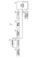
- FIG. 1 is a block diagram illustrating a configuration of the energy consumption prediction apparatus according to the embodiment.
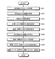
- FIG. 2 is a flowchart illustrating the processing contents of the energy consumption prediction apparatus according to the embodiment.
- FIG. 3 is a block diagram illustrating a hardware configuration example of the energy consumption prediction apparatus.
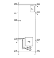
- FIG. 4 is a diagram for explaining the outline of speed prediction.
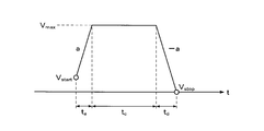
- FIG. 5 is a chart showing speed changes in a certain section.
- FIG. 6 is a flowchart showing details of speed prediction.
- FIG. 7 is a chart showing an example of speed prediction.
- FIG. 8 is a chart showing an example of position calculation calculated based on speed prediction.
- FIG. 9 is a chart showing a gradient calculation example calculated based on the position change.
- FIG. 10 is a diagram illustrating a configuration example of the driving force observer.
- FIG. 11 is a chart showing a motor efficiency map.
- FIG. 12 is a chart showing the energy consumption after calculation.
- FIG. 1 is a block diagram illustrating a configuration of the energy consumption prediction apparatus according to the embodiment.
- the energy consumption prediction apparatus 100 predicts energy consumption consumed when a vehicle travels on a planned travel route to a destination.
- the energy consumption prediction apparatus 100 includes a planned travel route calculation unit 101, a speed calculation unit 102, a travel resistance value calculation unit 103, a driving force calculation unit 104, a torque calculation unit 105, an efficiency map acquisition unit 106, A consumption energy calculation unit 107.
- the planned travel route calculation unit 101 calculates the planned travel route to the destination based on the input of the destination of the vehicle.
- the speed calculation unit 102 calculates speed information indicating the speed on the planned travel route.
- the running resistance value calculation unit 103 calculates a running resistance value based on the speed information.
- the driving force calculation unit 104 calculates the driving force of the vehicle based on the running resistance value.
- the torque calculation unit 105 calculates torque information indicating the torque of the planned travel route based on the driving force.
- the efficiency map acquisition unit 106 acquires a driving means for driving the vehicle, that is, an efficiency map of the motor.
- the efficiency map is a map for obtaining the efficiency of the motor from the torque and the speed, and has characteristics specific to the motor of the vehicle.
- the energy consumption calculation unit 107 calculates energy consumption based on speed information, torque information, and an efficiency map on the planned travel route. The calculated energy consumption information is displayed on a display unit (not shown) or output to the outside.
- the running resistance value calculation unit 103 can calculate the running resistance value based on the speed information calculated by the speed calculation unit 102 and the gradient information acquired by the gradient acquisition unit 108.
- FIG. 2 is a flowchart showing the processing contents of the energy consumption prediction apparatus according to the embodiment.
- the energy consumption prediction apparatus 100 predicts energy consumption in the following processing order.
- the planned travel route calculation unit 101 searches for a route (planned route) to the destination based on the input of the destination of the vehicle (step S201). Map information is used for this search.
- the speed calculation unit 102 predicts speed information indicating the speed on the planned travel route (step S202). At this time, the position and distance of the vehicle for each hour on the planned route can be obtained based on the calculated speed (step S203).
- the energy consumption at this position is calculated based on the position of the vehicle that is different every time.
- the gradient acquisition unit 108 calculates the gradient at this position from the map information (step S204). Then, the running resistance value calculation unit 103 calculates a running resistance value based on the calculated speed information and gradient information (step S205). Thereafter, the driving force calculation unit 104 calculates the driving force of the vehicle based on the calculated running resistance value (step S206).
- the torque calculation unit 105 calculates a necessary torque at this position based on the calculated driving force (step S207). Thereafter, the efficiency map acquisition unit 106 acquires an efficiency map of the vehicle motor, and calculates the efficiency at this position using the efficiency map based on the calculated speed and torque (step S208).
- the consumed energy calculation unit 107 calculates consumed energy based on the speed information, torque information, and efficiency map at this position (step S209).
- the calculated energy consumption information is displayed on a display unit (not shown) or output to the outside.
- the processing after step S204 is repeatedly executed for each position of the planned route.
- the planned route is divided into predetermined sections (for example, a node-node link (edge)), and energy consumption is calculated for each section.
- the torque on the planned route is calculated, and the efficiency of the motor of the vehicle is obtained from the torque and speed.
- the energy consumption of the planned route can be predicted.
- the energy consumed before the vehicle travels can be accurately predicted.
- FIG. 3 is a block diagram illustrating a hardware configuration example of the energy consumption prediction apparatus.
- the energy consumption prediction apparatus 100 includes a CPU 301, a ROM 302, a RAM 303, a communication I / F 304, a GPS unit 305, and various sensors 306. Each component 301 to 306 is connected by a bus 307.
- the CPU 301 governs overall control of the energy consumption prediction apparatus 100.
- the ROM 302 records and holds programs such as a boot program and an energy prediction program.
- the RAM 303 is used as a work area for the CPU 301. That is, the CPU 301 executes the program recorded in the ROM 302 while using the RAM 303 as a work area.
- the communication I / F 304 is connected to the network via wireless and functions as an interface between the energy consumption prediction apparatus 100 and the CPU 301.
- the communication network functioning as a network includes a public line network, a mobile phone network, DSRC (Dedicated Short Range Communication), LAN, WAN, and the like.
- the communication I / F 304 is, for example, a public line connection module, an ETC unit, an FM tuner, a VICS (Vehicle Information and Communication System (registered trademark)) / beacon receiver, or the like.
- the GPS unit 305 receives radio waves from GPS satellites and outputs information indicating the current position of the vehicle.
- the output information of the GPS unit 305 is used when the CPU 301 calculates the current position of the vehicle together with output values of various sensors such as a speed sensor, an acceleration sensor, and a yaw rate sensor.
- the information indicating the current position is information for specifying one point on the map data, such as latitude / longitude and altitude.
- Each configuration shown in FIG. 1 realizes its function by the CPU 301 executing a predetermined program using programs and data recorded in the ROM 302, RAM 303, and the like. And the energy consumption prediction apparatus 100 shown in FIG. 3 can be made into one function of a navigation apparatus.
- FIG. 4 is a diagram for explaining the outline of speed prediction.
- the process of step S202 will be described.
- the figure shows a planned travel route of the vehicle.
- a predetermined route (scheduled travel route) 401 that starts from the departure point (S) and returns to the destination (G, the same position as the departure point in the illustrated example) is shown.
- An example is shown.
- a route is divided into several sections based on map information, and a graph using feature points such as a signal p and a corner as a node is used.
- the edge (link) between the nodes has distance information for each edge, speed information, presence / absence of a signal, presence / absence of a corner, etc. as information necessary for speed prediction.
- each edge has rolling resistance coefficient and gradient information for each edge. These can be acquired not only from sensor detection but also from map information.
- the traveling speed for each section is predicted based on the edge information.
- the traveling speed is determined according to a predetermined rule. For example, a. The acceleration / deceleration is 0.1 [G]. b. When there is a signal at the edge of the corner, the speed at that point is set to 0 [km / h]. c. When the edge end is a corner and there is no signal, the speed at that point is set to 10 [km / h]. d. If the edge is not a corner but a signal, the speed is set to 0 [km / h]. Etc. Moreover, in speed prediction, not only the above-described rule is used, but also probe data obtained by actually traveling the vehicle can be used.
- FIG. 5 is a chart showing speed changes in a certain section.
- Vmax is a speed based on edge information (upper limit speed)
- Vstart which is the start point is the end speed in the previous section
- a is the acceleration determined based on the rule
- -a is based on the rule.
- the determined deceleration, Vstop is the terminal speed in this section determined based on the rule.
- FIG. 6 is a flowchart showing the detailed contents of speed prediction. A detailed processing example of step S202 in FIG. 2 will be described. First, it moves to the first node in the section (step S601). Then, it is determined whether this node is not the destination (step S602). If it is the destination (step S602: No), the process is terminated. If it is not the destination (step S602: Yes), the following process is performed. Do.
- the distance to the next node is calculated based on the map information or the like (step S603).
- the acceleration time ta, the deceleration time td, and the constant speed traveling time tc between the nodes are calculated from the distance / speed information between the nodes and the set acceleration / deceleration (step S604).
- the speed between nodes is calculated from the calculated acceleration time ta, deceleration time td, constant speed traveling time tc, speed information between the nodes, and the set acceleration / deceleration (step S605).
- the node moves to the next node (step S606), and returns to step S602.
- FIG. 7 is a chart showing an example of speed prediction.
- the horizontal axis is distance, and the vertical axis is speed.
- running route 401 of FIG. 4 is shown.
- the actual measurement result and the predicted speed (predicted speed) are described.
- position calculation and gradient calculation will be described.
- position changes are calculated in time series based on the speed prediction.
- the position calculation is performed based on the following formula.
- FIG. 8 is a chart showing an example of position calculation calculated based on speed prediction.
- the horizontal axis is time, and the vertical axis is distance.
- An example calculated based on the predicted speed of FIG. 7 is shown. As shown in the figure, the distance is integrated every time.
- FIG. 9 is a chart showing a gradient calculation example calculated based on the position change.
- the horizontal axis is time, and the vertical axis is gradient (angle).
- This gradient ⁇ [deg] can be obtained from the map information, and the gradient for each position is obtained.
- the map information is stored in, for example, the ROM 302 or the external storage unit illustrated in FIG. Or it can acquire from an external server etc. via communication I / F304.
- Fd [N] 1/2 ⁇ ⁇ C D Av 2 + ⁇ rmg + mg sin ⁇ + m (dv / dt) + Ri
- driving force [rho: air density
- C D C D value
- A front projected area
- .mu.r rolling resistance coefficient
- m vehicle weight
- g gravitational acceleration
- Ri Internal resistance
- the internal resistance is a resistance component other than air resistance, rolling resistance, gradient resistance, and acceleration resistance, including mechanical loss of the drive system, and is assumed to be a known one here.
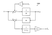
- FIG. 10 is a diagram illustrating a configuration example of the driving force observer.
- the torque T is the total torque per vehicle. (Where T: torque [Nm], J: tire inertia [Nms 2 ], ⁇ : tire rotation speed [rad / s], r: tire radius [m])
- ⁇ 1.29 [kg / m 3 ]
- C D 0.530
- A 1.28 [m 2 ]
- ⁇ r 0.0185
- m 395 [ kg].
- FIG. 11 is a chart showing a motor efficiency map.
- This efficiency map 1100 shows the relationship between the rotational speed on the horizontal axis and the torque on the vertical axis and the efficiency.
- the efficiency map 1100 has different characteristics for each motor mounted on the vehicle.
- the efficiency map 1100 is stored in advance in the ROM 302 or the external storage unit illustrated in FIG. Or it can acquire from an external server etc. via communication I / F304.
- the efficiency ⁇ can be obtained from the intersection corresponding to the rotational speed and the torque.
- the torque T is the total torque for each vehicle, and when the vehicle includes one motor, one efficiency map 1100 is used.
- the torque is different for each wheel.
- an in-wheel motor is provided for each of the four wheels, the total torque is simply divided by four to drive each motor, but the torque distribution of each wheel differs depending on the curve, gradient, and the like.
- a vehicle equipped with such a plurality of motors is provided with an efficiency map 1100 for the number of motors, resulting in an independent torque for each motor of each wheel, and correspondingly different efficiency.
- the consumed energy is calculated based on the speed, torque, and efficiency after each calculation described above.
- the consumed energy E is calculated by the following formula.
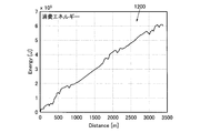
- FIG. 12 is a chart showing the energy consumption after calculation.
- the horizontal axis represents the distance, and the vertical axis represents the amount of electric power.
- the integrated value of the amount of energy consumed when the travel route 401 from the starting point to the destination shown in FIG. 4 is traced is shown.
- the calculated energy consumption amount can be output as an integrated amount as shown in FIG. 12 on a display unit or the like as a graph or numerical value, or output outside the apparatus.
- the vehicle is provided with all the functions of the energy consumption estimation device.
- the present invention is not limited to this.
- the configuration shown in FIG. 1 and FIG. 3, that is, the configuration relating to the energy consumption estimation may be provided in an external server, and the vehicle may be configured to include a terminal having only a function of communicating with the server.
- the server executes processing related to the energy consumption estimation
- the terminal of the vehicle is configured so that the server can detect information that can identify the motor mounted on the vehicle, such as the communication function with the server and the type of the vehicle. do it.
- the apparatus cost and processing burden on the vehicle side can be reduced.
- the amount of energy consumed to reach the destination can be accurately measured before the vehicle travels. Be able to predict.
- an appropriate charging point on the planned route can be planned in advance.
- the method described in this embodiment can be realized by executing a program prepared in advance on a computer such as a personal computer or a workstation.
- This program is recorded on a computer-readable recording medium such as a hard disk, a flexible disk, a CD-ROM, an MO, and a DVD, and is executed by being read from the recording medium by the computer.
- the program may be a transmission medium that can be distributed via a network such as the Internet.
Landscapes
- Engineering & Computer Science (AREA)
- Radar, Positioning & Navigation (AREA)
- Remote Sensing (AREA)
- Automation & Control Theory (AREA)
- Physics & Mathematics (AREA)
- General Physics & Mathematics (AREA)
- Power Engineering (AREA)
- Transportation (AREA)
- Mechanical Engineering (AREA)
- Navigation (AREA)
- Electric Propulsion And Braking For Vehicles (AREA)
Abstract
消費エネルギー予測装置(100)は、目的地までの走行予定経路を車両が走行する際に消費する消費エネルギーを予測するものであり、目的地に対応する走行予定経路を算出する走行予定経路算出部(101)と、走行予定経路における速度を示す速度情報を算出する速度算出部(102)と、速度情報に基づいて走行抵抗値を算出する走行抵抗値算出部(103)と、走行抵抗値に基づいて車両の駆動力を算出する駆動力算出部(104)と、駆動力に基づいて走行予定経路のトルクを示すトルク情報を算出するトルク算出部(105)と、車両を駆動するモータの効率マップを取得する効率マップ取得部(106)と、走行予定経路における速度情報、トルク情報、および効率マップに基づいて、消費エネルギーを算出する消費エネルギー算出部(107)とを備える。
Description
この発明は、車両のモータへ電源を供給し車両を駆動する消費エネルギー予測装置、消費エネルギー予測方法および消費エネルギー予測プログラムに関する。ただし、この発明の利用は、上述した消費エネルギー予測装置、消費エネルギー予測方法および消費エネルギー予測プログラムには限られない。
従来、移動体である電気自動車(EV)にモータを設け、車輪を駆動する構成において、モータを車輪に設けるインホイールモータ構造とし、このモータに対する電源を車両から供給するものとして、下記の各技術が開示されている。
たとえば、走行予定経路でのモータの消費エネルギー量を推定する際に、走行する車両に生じる走行抵抗その他の抵抗を考慮して、消費エネルギー量を推定する技術がある(たとえば、下記特許文献1参照。)。また、車両の速度および道路勾配を用い、省電力ルートと消費電力を推定する技術がある(たとえば、下記特許文献2参照。)。
しかしながら、上記いずれの技術においても、車両に設けられたモータの効率が考慮されておらず、モータ毎に効率が異なるため、いずれも消費エネルギーを精度よく求めることができず、推定した状態で実際に走行した後に推定と異なるためにバッテリ切れを起こす問題が生じることが考えられる。
上述した課題を解決し、目的を達成するため、この発明にかかる消費エネルギー予測装置は、目的地までの走行予定経路を車両が走行する際に消費する消費エネルギーを予測する消費エネルギー予測装置であって、前記目的地に対応する前記走行予定経路を算出する走行予定経路算出手段と、前記走行予定経路における速度を示す速度情報を算出する速度算出手段と、前記速度情報に基づいて走行抵抗値を算出する走行抵抗値算出手段と、前記走行抵抗値に基づいて前記車両の駆動力を算出する駆動力算出手段と、前記駆動力に基づいて前記走行予定経路のトルクを示すトルク情報を算出するトルク算出手段と、前記車両を駆動する駆動手段の効率マップを取得する効率マップ取得手段と、前記走行予定経路における前記速度情報、前記トルク情報、および前記効率マップに基づいて、前記消費エネルギーを算出する消費エネルギー算出手段と、を備えることを特徴とする。
また、この発明にかかる消費エネルギー予測方法は、目的地までの走行予定経路を車両が走行する際に消費する消費エネルギーを予測する消費エネルギー予測装置の消費エネルギー予測方法であって、前記目的地に対応する前記走行予定経路を算出する走行予定経路算出工程と、前記走行予定経路における速度を示す速度情報を算出する速度算出工程と、前記速度情報に基づいて走行抵抗値を算出する走行抵抗値算出工程と、前記走行抵抗値に基づいて前記車両の駆動力を算出する駆動力算出工程と、前記駆動力に基づいて前記走行予定経路のトルクを示すトルク情報を算出するトルク算出工程と、前記車両を駆動する駆動手段の効率マップを取得する効率マップ取得工程と、前記走行予定経路における前記速度情報、前記トルク情報、および前記効率マップに基づいて、前記消費エネルギーを算出する消費エネルギー算出工程と、を含むことを特徴とする。
また、この発明にかかる消費エネルギー予測プログラムは、目的地までの走行予定経路を車両が走行する際に消費する消費エネルギーを予測する消費エネルギー予測装置に適用されるプログラムであって、コンピュータを、前記目的地に対応する前記走行予定経路を算出する走行予定経路算出手段と、前記走行予定経路における速度を示す速度情報を算出する速度算出手段と、前記速度情報に基づいて走行抵抗値を算出する走行抵抗値算出手段と、前記走行抵抗値に基づいて前記車両の駆動力を算出する駆動力算出手段と、前記駆動力に基づいて前記走行予定経路のトルクを示すトルク情報を算出するトルク算出手段と、前記車両を駆動する駆動手段の効率マップを取得する効率マップ取得手段と、前記走行予定経路における前記速度情報、前記トルク情報、および前記効率マップに基づいて、前記消費エネルギーを算出する消費エネルギー算出手段、として機能させることを特徴とする。
(実施の形態)
以下に添付図面を参照して、この発明にかかる消費エネルギー予測装置、消費エネルギー予測方法および消費エネルギー予測プログラムの好適な実施の形態を詳細に説明する。以下の説明では、車両の各車輪にモータを備えたインホイール型の構成を例に説明するが、この発明は、モータを備えた車両の消費エネルギー予測を行うものであり、モータはインホイールモータに限らず適用できる。
以下に添付図面を参照して、この発明にかかる消費エネルギー予測装置、消費エネルギー予測方法および消費エネルギー予測プログラムの好適な実施の形態を詳細に説明する。以下の説明では、車両の各車輪にモータを備えたインホイール型の構成を例に説明するが、この発明は、モータを備えた車両の消費エネルギー予測を行うものであり、モータはインホイールモータに限らず適用できる。
(消費エネルギー予測装置の構成)
図1は、実施の形態にかかる消費エネルギー予測装置の構成を示すブロック図である。消費エネルギー予測装置100は、目的地までの走行予定経路を車両が走行する際に消費する消費エネルギーを予測する。この消費エネルギー予測装置100は、走行予定経路算出部101と、速度算出部102と、走行抵抗値算出部103と、駆動力算出部104と、トルク算出部105と、効率マップ取得部106と、消費エネルギー算出部107とを有する。また、走行予定経路における勾配を示す勾配情報を取得する勾配取得部108を備えた構成としてもよい。
図1は、実施の形態にかかる消費エネルギー予測装置の構成を示すブロック図である。消費エネルギー予測装置100は、目的地までの走行予定経路を車両が走行する際に消費する消費エネルギーを予測する。この消費エネルギー予測装置100は、走行予定経路算出部101と、速度算出部102と、走行抵抗値算出部103と、駆動力算出部104と、トルク算出部105と、効率マップ取得部106と、消費エネルギー算出部107とを有する。また、走行予定経路における勾配を示す勾配情報を取得する勾配取得部108を備えた構成としてもよい。
走行予定経路算出部101は、車両の目的地の入力に基づき、目的地までの走行予定経路を算出する。速度算出部102は、走行予定経路における速度を示す速度情報を算出する。走行抵抗値算出部103は、速度情報に基づいて走行抵抗値を算出する。駆動力算出部104は、走行抵抗値に基づいて車両の駆動力を算出する。トルク算出部105は、駆動力に基づいて走行予定経路のトルクを示すトルク情報を算出する。
効率マップ取得部106は、車両を駆動する駆動手段、すなわちモータの効率マップを取得する。効率マップは、トルクと速度からモータの効率を得るためのマップであり、車両のモータに固有の特性を有する。消費エネルギー算出部107は、走行予定経路における速度情報、トルク情報、および効率マップに基づいて、消費エネルギーを算出する。算出された消費エネルギーの情報は、図示しない表示部に表示されたり、外部へ出力されたりする。
また、走行抵抗値算出部103は、速度算出部102で算出された速度情報および勾配取得部108により取得された勾配情報に基づいて走行抵抗値を算出することができる。
図2は、実施の形態にかかる消費エネルギー予測装置の処理内容を示すフローチャートである。消費エネルギー予測装置100は、以下の処理順に消費エネルギーを予測する。はじめに、走行予定経路算出部101により、車両の目的地の入力に基づき、目的地までのルート(予定経路)を探索する(ステップS201)。この探索には、地図情報を用いる。次に、速度算出部102により、走行予定経路における速度を示す速度情報を予測する(ステップS202)。この際、算出された速度により、予定経路上における車両の時間毎の位置、および距離を得ることができる(ステップS203)。以下の処理では、この時間毎に異なる車両の位置に基づき、この位置での消費エネルギーをそれぞれ算出する。
はじめに、車両の予定経路上での位置に基づき、勾配取得部108は地図情報からこの位置での勾配を算出する(ステップS204)。そして、走行抵抗値算出部103は、算出された速度情報と、勾配情報に基づいて走行抵抗値を算出する(ステップS205)。この後、駆動力算出部104は、算出された走行抵抗値に基づいて車両の駆動力を算出する(ステップS206)。
次に、トルク算出部105により、算出された駆動力に基づいてこの位置における必要なトルクを算出する(ステップS207)。この後、効率マップ取得部106は、車両のモータの効率マップを取得し、算出された速度とトルクに基づき、効率マップを用いてこの位置での効率を算出する(ステップS208)。
この後、消費エネルギー算出部107は、この位置での速度情報、トルク情報、および効率マップに基づいて、消費エネルギーを算出する(ステップS209)。算出された消費エネルギーの情報は、図示しない表示部に表示されたり、外部へ出力されたりする。ステップS204以下の処理は、予定経路の各位置について繰り返し実行される。たとえば、予定経路を所定の区間(たとえばノード-ノード間のリンク(エッジ))毎に分割し、この区間毎に消費エネルギーを算出する。
上記構成によれば、車両に搭載されたモータの特性を考慮し、予定経路上でのトルクを算出し、トルクと速度からモータの効率を得る車両のモータに固有の効率マップを利用して、予定経路の消費エネルギーを予測することができるようになる。これにより、車両の走行前に消費するエネルギーを精度よく予測できるようになる。
(消費エネルギー予測装置のハードウェア構成)
次に、上記実施形態の実施例について説明する。図3は、消費エネルギー予測装置のハードウェア構成例を示すブロック図である。図3において、消費エネルギー予測装置100は、CPU301、ROM302、RAM303、通信I/F304、GPSユニット305、各種センサ306を備えている。各構成部301~306は、バス307によってそれぞれ接続されている。
次に、上記実施形態の実施例について説明する。図3は、消費エネルギー予測装置のハードウェア構成例を示すブロック図である。図3において、消費エネルギー予測装置100は、CPU301、ROM302、RAM303、通信I/F304、GPSユニット305、各種センサ306を備えている。各構成部301~306は、バス307によってそれぞれ接続されている。
CPU301は、消費エネルギー予測装置100の全体の制御を司る。ROM302は、ブートプログラム、エネルギー予測プログラムなどのプログラムなどを記録保持する。RAM303は、CPU301のワークエリアとして使用される。すなわち、CPU301は、RAM303をワークエリアとして使用しながら、ROM302に記録されたプログラムを実行する。
通信I/F304は、無線を介してネットワークに接続され、消費エネルギー予測装置100およびCPU301のインターフェースとして機能する。ネットワークとして機能する通信網には、公衆回線網や携帯電話網、DSRC(Dedicated Short Range Communication)、LAN、WANなどがある。通信I/F304は、たとえば、公衆回線用接続モジュールやETCユニット、FMチューナー、VICS(Vehicle Information and Communication System(登録商標))/ビーコンレシーバなどである。
GPSユニット305は、GPS衛星からの電波を受信し、車両の現在位置を示す情報を出力する。GPSユニット305の出力情報は、速度センサ、加速度センサ、ヨーレートセンサ等の各種センサの出力値とともに、CPU301による車両の現在位置の算出に際して利用される。現在位置を示す情報は、たとえば、緯度・経度、高度などの、地図データ上の1点を特定する情報である。
図1に示した各構成は、ROM302、RAM303、等に記録されたプログラムやデータを用いて、CPU301が所定のプログラムを実行することによってその機能を実現する。そして、図3に示した消費エネルギー予測装置100は、ナビゲーション装置の一機能とすることができる。
(速度予測について)
図4は、速度予測の概要を説明する図である。上記ステップS202の処理を説明する。図には車両の走行予定経路を示してあり、出発地(S)から出発し、目的地(G、図示の例では出発地と同位置)に戻る所定のルート(予定の走行経路)401の例を示している。
図4は、速度予測の概要を説明する図である。上記ステップS202の処理を説明する。図には車両の走行予定経路を示してあり、出発地(S)から出発し、目的地(G、図示の例では出発地と同位置)に戻る所定のルート(予定の走行経路)401の例を示している。
1.はじめに、速度予測では、地図情報に基づき、ルートをいくつかの区間に分割し、特徴点、たとえば信号pや曲がり角をノード(node)としたグラフを用いる。また、ノード-ノード間のエッジ(リンク)には、速度予測に必要な情報として、エッジ毎の距離情報、速度情報、信号の有無、曲がり角の有無等、を持たせておく。また、各エッジ毎にエッジ毎の転がり抵抗係数や、勾配の情報を持つ構成にできる。これらはセンサ検出に限らず地図情報から取得することができる。
2.次に、エッジの情報を基に、各区間毎の走行速度を予測する。この際には、あらかじめ定めた所定のルールに従い走行速度を決定する。たとえば、
a.加速度/減速度は0.1[G]とする。
b.エッジ端が曲がり角で信号がある場合はその点での速度を0[km/h]とする。
c.エッジ端が曲がり角で信号がない場合はその点での速度を10[km/h]とする。
d.エッジ端が曲がり角でなく信号がある場合は速度を0[km/h]とする。
等がある。
また、速度予測にあたり、上記のルールを用いるに限らず、車両が実際に走行して得たプローブデータを用いることもできる。
a.加速度/減速度は0.1[G]とする。
b.エッジ端が曲がり角で信号がある場合はその点での速度を0[km/h]とする。
c.エッジ端が曲がり角で信号がない場合はその点での速度を10[km/h]とする。
d.エッジ端が曲がり角でなく信号がある場合は速度を0[km/h]とする。
等がある。
また、速度予測にあたり、上記のルールを用いるに限らず、車両が実際に走行して得たプローブデータを用いることもできる。
3.次に、エッジの情報を基に、各区間毎の速度を予測する。図5は、ある区間での速度変化を示す図表である。図中、Vmaxはエッジの情報に基づく速度(上限速度)、始点であるVstartは、前の区間における終端速度、aの勾配は、ルールに基づき決めた加速度、-aの勾配は、ルールに基づき定めた減速度、Vstopは、ルールに基づき決めたこの区間における終端速度、である。
この一つ区間における各時間は下記式により得ることができる。
加速時間ta=(Vmax-Vstart)/a
減速時間td=(Vmax-Vstop)/a
定速走行時間tc=[X-((Vstart・ta)/2)+((Vstop・td)/2)/Vmax}-[(ta/2)+(td/2)]
(ただし、X:この区間の距離である)
加速時間ta=(Vmax-Vstart)/a
減速時間td=(Vmax-Vstop)/a
定速走行時間tc=[X-((Vstart・ta)/2)+((Vstop・td)/2)/Vmax}-[(ta/2)+(td/2)]
(ただし、X:この区間の距離である)
図6は、速度予測の詳細内容を示すフローチャートである。図2のステップS202の詳細な処理例について説明する。はじめに、区間の最初のノードへ移動する(ステップS601)。そして、このノードが目的地でないか判断し(ステップS602)、目的地であれば(ステップS602:No)、処理を終了するが、目的地でなければ(ステップS602:Yes)、以下の処理を行う。
まず、次のノードまでの距離を地図情報等に基づき算出する(ステップS603)。そして、ノード間の距離/速度情報および設定された加減速度からノード間での加速時間ta、減速時間td、定速走行時間tcを算出する(ステップS604)。この後、算出したノード間での加速時間ta、減速時間td、定速走行時間tcおよびノード間の速度情報と、設定された加減速度からノード間の速度を算出する(ステップS605)。この後、次のノードへ移動し(ステップS606)、ステップS602に戻る。
図7は、速度予測例を示す図表である。横軸は距離、縦軸は速度である。図4の走行経路401における時間毎の速度の変化を示している。この図には実測した測定結果と予測した速度(予測速度)を記載してある。
(位置、勾配算出について)
次に、位置算出および勾配算出について説明する。位置算出については、上記速度予測に基づき時系列に位置変化を算出する。位置算出は、下記式に基づき行う。
次に、位置算出および勾配算出について説明する。位置算出については、上記速度予測に基づき時系列に位置変化を算出する。位置算出は、下記式に基づき行う。

図8は、速度予測に基づき算出した位置算出例を示す図表である。横軸は時間、縦軸は距離である。図7の予測速度に基づき算出した例を示している。図示のように、時間毎に積算された距離となる。
次に、勾配算出は、位置変化から時系列の勾配変化を算出する。図9は、位置変化に基づき算出した勾配算出例を示す図表である。横軸は時間、縦軸は勾配(角度)である。この勾配θ[deg]は、地図情報から得ることができ、位置毎の勾配を得る。地図情報は、たとえば、図3に記載のROM302や外部記憶部に記憶される。あるいは通信I/F304を介して外部のサーバ等から取得することができる。
(走行抵抗/駆動力算出、トルク算出について)
次に、走行抵抗、駆動力算出について説明する。走行抵抗は、上記の速度と勾配に基づき算出する。駆動力はこの走行抵抗から算出する。駆動力=空気抵抗+転がり抵抗+勾配抵抗+加速抵抗+内部抵抗で得ることができ、下記式に基づき算出する。
Fd[N]=1/2・ρCDAv2+μrmg+mgsinθ+m(dv/dt)+Ri
(Fd:駆動力、ρ:空気密度、CD:CD値、A:前面投影面積、μr:転がり抵抗係数、m:車重、g:重力加速度、Ri:内部抵抗)
なお、内部抵抗とは、駆動系の機械損失を含む、空気抵抗、転がり抵抗、勾配抵抗、加速抵抗以外の抵抗成分のことであり、ここでは既知のものであると仮定している。
次に、走行抵抗、駆動力算出について説明する。走行抵抗は、上記の速度と勾配に基づき算出する。駆動力はこの走行抵抗から算出する。駆動力=空気抵抗+転がり抵抗+勾配抵抗+加速抵抗+内部抵抗で得ることができ、下記式に基づき算出する。
Fd[N]=1/2・ρCDAv2+μrmg+mgsinθ+m(dv/dt)+Ri
(Fd:駆動力、ρ:空気密度、CD:CD値、A:前面投影面積、μr:転がり抵抗係数、m:車重、g:重力加速度、Ri:内部抵抗)
なお、内部抵抗とは、駆動系の機械損失を含む、空気抵抗、転がり抵抗、勾配抵抗、加速抵抗以外の抵抗成分のことであり、ここでは既知のものであると仮定している。
トルクは、上記の駆動力から算出する。図10は、駆動力オブザーバの構成例を示す図である。ここで、トルクTは、図に示した構成の駆動力オブザーバ1000の入出力を逆算することにより得ることができる。すなわち、
T=J・(dω/dt)+rFd
により得ることができる。なお、トルクTは、車両あたりの全トルクである。
(ただし、T:トルク[Nm]、J:タイヤイナーシャ[Nms2]、ω:タイヤの回転速度[rad/s]、r:タイヤ半径[m])
T=J・(dω/dt)+rFd
により得ることができる。なお、トルクTは、車両あたりの全トルクである。
(ただし、T:トルク[Nm]、J:タイヤイナーシャ[Nms2]、ω:タイヤの回転速度[rad/s]、r:タイヤ半径[m])
上記各パラメータの数値例としては、たとえば、ρ=1.29[kg/m3]、CD=0.530、A=1.28[m2]、μr=0.0185、m=395[kg]である。
(効率算出について)
図11は、モータの効率マップを示す図表である。この効率マップ1100は、横軸の回転速度および縦軸のトルクと効率の関係を示したものである。この効率マップ1100は、車両に搭載されるモータ毎に特性が異なり、たとえば、あらかじめ近似式として、あるいはテーブル化して図3に記載のROM302や外部記憶部に記憶される。あるいは通信I/F304を介して外部のサーバ等から取得することができる。この効率マップ1100を用いることにより、回転速度とトルクに対応する交点から効率ηを求めることができる。
図11は、モータの効率マップを示す図表である。この効率マップ1100は、横軸の回転速度および縦軸のトルクと効率の関係を示したものである。この効率マップ1100は、車両に搭載されるモータ毎に特性が異なり、たとえば、あらかじめ近似式として、あるいはテーブル化して図3に記載のROM302や外部記憶部に記憶される。あるいは通信I/F304を介して外部のサーバ等から取得することができる。この効率マップ1100を用いることにより、回転速度とトルクに対応する交点から効率ηを求めることができる。
効率ηは下記のように、トルクと回転速度に関する関数として近似式で表現することができる。
η=f(T,ω)
η=f(T,ω)
なお、上記のトルクTは、車両毎の全トルクであり、車両が一つのモータを備える場合には、一つの効率マップ1100を利用する。車両が各輪にインホイールモータを備えた複数モータを有する場合には、車輪毎に異なるトルクとなる。たとえば4輪にそれぞれインホイールモータが設けられた場合、単純には全トルクを4で割りそれぞれのモータを駆動するが、カーブや勾配等により、各輪のトルク配分が異なる。このため、このような複数のモータを備えた車両では、モータ数分の効率マップ1100を備え、各車輪のモータ毎に独立したトルクとなり、対応して異なる効率を求めることになる。
(消費エネルギー算出について)
消費エネルギーは、上述した各算出後の速度、トルク、効率に基づき算出される。消費エネルギーEは、下記式により算出される。
消費エネルギーは、上述した各算出後の速度、トルク、効率に基づき算出される。消費エネルギーEは、下記式により算出される。

図12は、算出後の消費エネルギーを示す図表である。横軸は距離、縦軸は電力量であり、図4に示した出発地から目的地までの走行経路401を辿ったときに消費されるエネルギー量の積算値が示されている。算出された消費エネルギー量は、図12のような積算量をグラフあるいは数値で表示部等に表示出力したり、装置外部に出力することができる。
図12に示した結果によれば、消費エネルギー量の増加の傾向や程度、および目的地に到達するまでの間に消費する最終的な消費エネルギー量を簡単に知ることができるようになる。
上記の実施例では、車両に消費エネルギー推定装置の全機能を搭載する構成としたが、これに限らない。たとえば、図1および図3に示した構成、すなわち、消費エネルギー推定にかかる構成を外部サーバに設け、車両はサーバと通信する機能だけを有する端末を設ける構成とすることもできる。この場合、サーバが消費エネルギー推定にかかる処理を実行し、車両の端末は、サーバとの間の通信機能と、車両の種別等、車両に搭載したモータを特定できる情報をサーバが検出できるよう構成すればよい。このような構成とすれば、車両側の装置コストおよび処理負担を軽減できるようになる。
以上説明したように、車両の予定経路に関する情報と、車両のモータに固有の特性を有する効率マップを用いることにより、車両の走行前の状態で、目的地に至るまでの消費エネルギー量を精度よく予測できるようになる。これにより、予定経路上での適切な充電ポイントを事前に計画することもできるようになる。
なお、本実施の形態で説明した方法は、あらかじめ用意されたプログラムをパーソナル・コンピュータやワークステーションなどのコンピュータで実行することにより実現することができる。このプログラムは、ハードディスク、フレキシブルディスク、CD-ROM、MO、DVDなどのコンピュータで読み取り可能な記録媒体に記録され、コンピュータによって記録媒体から読み出されることによって実行される。またこのプログラムは、インターネットなどのネットワークを介して配布することが可能な伝送媒体であってもよい。
100 消費エネルギー予測装置
101 走行予定経路算出部
102 速度算出部
103 走行抵抗値算出部
104 駆動力算出部
105 トルク算出部
106 効率マップ取得部
107 消費エネルギー算出部
108 勾配取得部
305 GPSユニット
306 各種センサ
307 バス
401 走行経路
1000 駆動力オブザーバ
1100 効率マップ
101 走行予定経路算出部
102 速度算出部
103 走行抵抗値算出部
104 駆動力算出部
105 トルク算出部
106 効率マップ取得部
107 消費エネルギー算出部
108 勾配取得部
305 GPSユニット
306 各種センサ
307 バス
401 走行経路
1000 駆動力オブザーバ
1100 効率マップ
Claims (5)
- 目的地までの走行予定経路を車両が走行する際に消費する消費エネルギーを予測する消費エネルギー予測装置であって、
前記目的地に対応する前記走行予定経路を算出する走行予定経路算出手段と、
前記走行予定経路における速度を示す速度情報を算出する速度算出手段と、
前記速度情報に基づいて走行抵抗値を算出する走行抵抗値算出手段と、
前記走行抵抗値に基づいて前記車両の駆動力を算出する駆動力算出手段と、
前記駆動力に基づいて前記走行予定経路のトルクを示すトルク情報を算出するトルク算出手段と、
前記車両を駆動する駆動手段の効率マップを取得する効率マップ取得手段と、
前記走行予定経路における前記速度情報、前記トルク情報、および前記効率マップに基づいて、前記消費エネルギーを算出する消費エネルギー算出手段と、
を備えることを特徴とする消費エネルギー予測装置。 - 前記走行予定経路における勾配を示す勾配情報を取得する勾配取得手段をさらに備え、
前記走行抵抗値算出手段は、前記速度情報および前記勾配情報に基づいて前記走行抵抗値を算出することを特徴とする請求項1に記載の消費エネルギー予測装置。 - 前記トルク算出手段は、
前記トルクをT、前記駆動力をFd、前記車両に搭載された車輪の慣性モーメントをJ、前記車輪の角速度をω、前記車輪の半径をr、経過時間をtとすると、
T=J・(dω/dt)+rFd
により前記トルクの変化を算出することを特徴とする請求項1に記載の消費エネルギー予測装置。 - 目的地までの走行予定経路を車両が走行する際に消費する消費エネルギーを予測する消費エネルギー予測装置の消費エネルギー予測方法であって、
前記目的地に対応する前記走行予定経路を算出する走行予定経路算出工程と、
前記走行予定経路における速度を示す速度情報を算出する速度算出工程と、
前記速度情報に基づいて走行抵抗値を算出する走行抵抗値算出工程と、
前記走行抵抗値に基づいて前記車両の駆動力を算出する駆動力算出工程と、
前記駆動力に基づいて前記走行予定経路のトルクを示すトルク情報を算出するトルク算出工程と、
前記車両を駆動する駆動手段の効率マップを取得する効率マップ取得工程と、
前記走行予定経路における前記速度情報、前記トルク情報、および前記効率マップに基づいて、前記消費エネルギーを算出する消費エネルギー算出工程と、
を含むことを特徴とする消費エネルギー予測方法。 - 目的地までの走行予定経路を車両が走行する際に消費する消費エネルギーを予測する消費エネルギー予測装置に適用される消費エネルギー予測プログラムであって、
コンピュータを、
前記目的地に対応する前記走行予定経路を算出する走行予定経路算出手段と、
前記走行予定経路における速度を示す速度情報を算出する速度算出手段と、
前記速度情報に基づいて走行抵抗値を算出する走行抵抗値算出手段と、
前記走行抵抗値に基づいて前記車両の駆動力を算出する駆動力算出手段と、
前記駆動力に基づいて前記走行予定経路のトルクを示すトルク情報を算出するトルク算出手段と、
前記車両を駆動する駆動手段の効率マップを取得する効率マップ取得手段と、
前記走行予定経路における前記速度情報、前記トルク情報、および前記効率マップに基づいて、前記消費エネルギーを算出する消費エネルギー算出手段、
として機能させることを特徴とする消費エネルギー予測プログラム。
Priority Applications (1)
| Application Number | Priority Date | Filing Date | Title |
|---|---|---|---|
| PCT/JP2011/079734 WO2013094045A1 (ja) | 2011-12-21 | 2011-12-21 | 消費エネルギー予測装置、消費エネルギー予測方法および消費エネルギー予測プログラム |
Applications Claiming Priority (1)
| Application Number | Priority Date | Filing Date | Title |
|---|---|---|---|
| PCT/JP2011/079734 WO2013094045A1 (ja) | 2011-12-21 | 2011-12-21 | 消費エネルギー予測装置、消費エネルギー予測方法および消費エネルギー予測プログラム |
Publications (1)
| Publication Number | Publication Date |
|---|---|
| WO2013094045A1 true WO2013094045A1 (ja) | 2013-06-27 |
Family
ID=48667969
Family Applications (1)
| Application Number | Title | Priority Date | Filing Date |
|---|---|---|---|
| PCT/JP2011/079734 Ceased WO2013094045A1 (ja) | 2011-12-21 | 2011-12-21 | 消費エネルギー予測装置、消費エネルギー予測方法および消費エネルギー予測プログラム |
Country Status (1)
| Country | Link |
|---|---|
| WO (1) | WO2013094045A1 (ja) |
Cited By (7)
| Publication number | Priority date | Publication date | Assignee | Title |
|---|---|---|---|---|
| GB2546565A (en) * | 2016-01-20 | 2017-07-26 | Mahindra Reva Electric Vehicles Ltd | A method and system for trip planning for vehicles with limited on-board energy |
| CN106989752A (zh) * | 2016-01-20 | 2017-07-28 | 马亨德拉雷瓦电动汽车有限公司 | 对具有有限的车载能量的车辆规划旅程的方法和系统 |
| JP2020059363A (ja) * | 2018-10-09 | 2020-04-16 | トヨタ自動車株式会社 | ハイブリッド車両の制御装置、及びハイブリッド車両の制御システム |
| US10875534B2 (en) | 2016-05-27 | 2020-12-29 | Hitachi Automotive Systems, Ltd. | Vehicle control device |
| CN112677777A (zh) * | 2021-01-21 | 2021-04-20 | 广州橙行智动汽车科技有限公司 | 一种数据处理方法、装置和车辆 |
| CN113276683A (zh) * | 2021-07-23 | 2021-08-20 | 江铃汽车股份有限公司 | 电动车电耗计算方法及系统 |
| CN116691371A (zh) * | 2023-05-09 | 2023-09-05 | 吉林大学 | 一种分布式驱动车辆动力系统能耗优化方法 |
Citations (4)
| Publication number | Priority date | Publication date | Assignee | Title |
|---|---|---|---|---|
| JPH09310638A (ja) * | 1996-05-20 | 1997-12-02 | Denso Corp | エンジン制御装置及び加速指令装置 |
| JP2002188932A (ja) * | 2000-12-21 | 2002-07-05 | Toyota Motor Corp | ナビゲーション装置 |
| JP2009067350A (ja) * | 2007-09-18 | 2009-04-02 | Aisin Aw Co Ltd | 車両消費エネルギ推定装置、車両消費エネルギ推定方法及びコンピュータプログラム |
| JP2011016465A (ja) * | 2009-07-09 | 2011-01-27 | Toyota Motor Corp | 車両用走行エネルギー演算システム |
-
2011
- 2011-12-21 WO PCT/JP2011/079734 patent/WO2013094045A1/ja not_active Ceased
Patent Citations (4)
| Publication number | Priority date | Publication date | Assignee | Title |
|---|---|---|---|---|
| JPH09310638A (ja) * | 1996-05-20 | 1997-12-02 | Denso Corp | エンジン制御装置及び加速指令装置 |
| JP2002188932A (ja) * | 2000-12-21 | 2002-07-05 | Toyota Motor Corp | ナビゲーション装置 |
| JP2009067350A (ja) * | 2007-09-18 | 2009-04-02 | Aisin Aw Co Ltd | 車両消費エネルギ推定装置、車両消費エネルギ推定方法及びコンピュータプログラム |
| JP2011016465A (ja) * | 2009-07-09 | 2011-01-27 | Toyota Motor Corp | 車両用走行エネルギー演算システム |
Cited By (13)
| Publication number | Priority date | Publication date | Assignee | Title |
|---|---|---|---|---|
| CN106989752B (zh) * | 2016-01-20 | 2020-07-17 | 马亨德拉雷瓦电动汽车有限公司 | 对具有有限的车载能量的车辆规划旅程的方法和系统 |
| CN106989752A (zh) * | 2016-01-20 | 2017-07-28 | 马亨德拉雷瓦电动汽车有限公司 | 对具有有限的车载能量的车辆规划旅程的方法和系统 |
| GB2546565A (en) * | 2016-01-20 | 2017-07-26 | Mahindra Reva Electric Vehicles Ltd | A method and system for trip planning for vehicles with limited on-board energy |
| US10875534B2 (en) | 2016-05-27 | 2020-12-29 | Hitachi Automotive Systems, Ltd. | Vehicle control device |
| US11318927B2 (en) | 2018-10-09 | 2022-05-03 | Toyota Jidosha Kabushiki Kaisha | Control device for hybrid vehicle and control system for hybrid vehicle |
| CN111016875A (zh) * | 2018-10-09 | 2020-04-17 | 丰田自动车株式会社 | 混合动力车辆的控制装置及混合动力车辆的控制系统 |
| JP2020059363A (ja) * | 2018-10-09 | 2020-04-16 | トヨタ自動車株式会社 | ハイブリッド車両の制御装置、及びハイブリッド車両の制御システム |
| JP7091987B2 (ja) | 2018-10-09 | 2022-06-28 | トヨタ自動車株式会社 | ハイブリッド車両の制御装置、及びハイブリッド車両の制御システム |
| CN112677777A (zh) * | 2021-01-21 | 2021-04-20 | 广州橙行智动汽车科技有限公司 | 一种数据处理方法、装置和车辆 |
| CN112677777B (zh) * | 2021-01-21 | 2022-10-14 | 广州橙行智动汽车科技有限公司 | 一种数据处理方法、装置和车辆 |
| CN113276683A (zh) * | 2021-07-23 | 2021-08-20 | 江铃汽车股份有限公司 | 电动车电耗计算方法及系统 |
| CN113276683B (zh) * | 2021-07-23 | 2021-10-08 | 江铃汽车股份有限公司 | 电动车电耗计算方法及系统 |
| CN116691371A (zh) * | 2023-05-09 | 2023-09-05 | 吉林大学 | 一种分布式驱动车辆动力系统能耗优化方法 |
Similar Documents
| Publication | Publication Date | Title |
|---|---|---|
| US20240094734A1 (en) | Power management, dynamic routing and memory management for autonomous driving vehicles | |
| JP5029494B2 (ja) | 走行エネルギー学習装置、方法およびプログラム | |
| JP4861534B1 (ja) | エネルギー消費量推定装置、エネルギー消費量推定方法、エネルギー消費量推定プログラムおよび記録媒体 | |
| JP5926558B2 (ja) | 車両用情報システムおよびサーバ装置 | |
| WO2013094045A1 (ja) | 消費エネルギー予測装置、消費エネルギー予測方法および消費エネルギー予測プログラム | |
| US9835463B2 (en) | Route searching device, terminal device, and route searching method | |
| JPWO2014168023A1 (ja) | エネルギー消費量予測装置およびエネルギー消費量予測方法 | |
| US9346362B2 (en) | Energy estimation device, information system for automotive, and server device | |
| JP2012255757A (ja) | エネルギー消費量計算装置とそのエネルギー消費量計算方法 | |
| JP2013070515A (ja) | 電動車両の充電制御システム | |
| WO2014049878A1 (ja) | 消費エネルギー推定装置、消費エネルギー推定方法、消費エネルギー推定プログラムおよび記録媒体 | |
| JP4863086B2 (ja) | 運転支援装置及びナビゲーション装置及びコンピュータプログラム | |
| JP6183419B2 (ja) | 経路案内装置、経路案内方法及びコンピュータプログラム | |
| JP5841388B2 (ja) | 燃料消費量予測装置、ナビゲーション装置、燃料消費量予測方法 | |
| JP5387853B2 (ja) | 走行可能距離算出装置及びこれを用いた車両 | |
| JP5687363B2 (ja) | 消費エネルギー予測装置、消費エネルギー予測方法および消費エネルギー予測プログラム | |
| JP4890659B1 (ja) | エネルギー消費量推定装置、エネルギー消費量推定方法、エネルギー消費量推定プログラムおよび記録媒体 | |
| JP2010091454A (ja) | 車両走行速度測定装置 | |
| JP4932057B2 (ja) | エネルギー消費量推定装置、エネルギー消費量推定方法、エネルギー消費量推定プログラムおよび記録媒体 | |
| JPWO2013094045A1 (ja) | 消費エネルギー予測装置、消費エネルギー予測方法および消費エネルギー予測プログラム | |
| WO2014162526A1 (ja) | 消費エネルギー量推定装置、消費エネルギー量推定方法、消費エネルギー量推定プログラムおよび記録媒体 | |
| JP2012163509A (ja) | 車両用推定航法装置、車両用推定航法及び車両用推定航法のプログラム | |
| JP2015190830A (ja) | 消費エネルギー推定装置、通信装置、消費エネルギー推定方法、消費エネルギー推定プログラム | |
| JP4959862B2 (ja) | 走行距離推定装置、走行距離推定方法、走行距離推定プログラムおよび記録媒体 | |
| JP2020161125A (ja) | 消費エネルギー推定装置、通信装置、消費エネルギー推定方法、消費エネルギー推定プログラム |
Legal Events
| Date | Code | Title | Description |
|---|---|---|---|
| 121 | Ep: the epo has been informed by wipo that ep was designated in this application |
Ref document number: 11878002 Country of ref document: EP Kind code of ref document: A1 |
|
| ENP | Entry into the national phase |
Ref document number: 2013550019 Country of ref document: JP Kind code of ref document: A |
|
| NENP | Non-entry into the national phase |
Ref country code: DE |
|
| 122 | Ep: pct application non-entry in european phase |
Ref document number: 11878002 Country of ref document: EP Kind code of ref document: A1 |