WO2013089531A1 - 다중 셀 시스템에서 물리 채널에 대한 자원 매핑 방법 및 장치 - Google Patents

다중 셀 시스템에서 물리 채널에 대한 자원 매핑 방법 및 장치 Download PDF

Info

Publication number
WO2013089531A1
WO2013089531A1 PCT/KR2012/011002 KR2012011002W WO2013089531A1 WO 2013089531 A1 WO2013089531 A1 WO 2013089531A1 KR 2012011002 W KR2012011002 W KR 2012011002W WO 2013089531 A1 WO2013089531 A1 WO 2013089531A1
Authority
WO
WIPO (PCT)
Prior art keywords
transmission
downlink
cell
data channel
pdsch
Prior art date
Application number
PCT/KR2012/011002
Other languages
English (en)
French (fr)
Inventor
서한별
서인권
김기준
Original Assignee
엘지전자 주식회사
Priority date (The priority date is an assumption and is not a legal conclusion. Google has not performed a legal analysis and makes no representation as to the accuracy of the date listed.)
Filing date
Publication date
Application filed by 엘지전자 주식회사 filed Critical 엘지전자 주식회사
Priority to KR1020147016834A priority Critical patent/KR101967298B1/ko
Priority to CN201280062163.1A priority patent/CN103999375B/zh
Priority to US14/361,639 priority patent/US10251165B2/en
Priority to ES12857425.8T priority patent/ES2609357T3/es
Priority to EP12857425.8A priority patent/EP2793406B1/en
Publication of WO2013089531A1 publication Critical patent/WO2013089531A1/ko

Links

Classifications

    • HELECTRICITY
    • H04ELECTRIC COMMUNICATION TECHNIQUE
    • H04WWIRELESS COMMUNICATION NETWORKS
    • H04W72/00Local resource management
    • H04W72/20Control channels or signalling for resource management
    • H04W72/23Control channels or signalling for resource management in the downlink direction of a wireless link, i.e. towards a terminal
    • HELECTRICITY
    • H04ELECTRIC COMMUNICATION TECHNIQUE
    • H04LTRANSMISSION OF DIGITAL INFORMATION, e.g. TELEGRAPHIC COMMUNICATION
    • H04L5/00Arrangements affording multiple use of the transmission path
    • H04L5/0001Arrangements for dividing the transmission path
    • H04L5/0003Two-dimensional division
    • H04L5/0005Time-frequency
    • H04L5/0007Time-frequency the frequencies being orthogonal, e.g. OFDM(A), DMT
    • H04L5/001Time-frequency the frequencies being orthogonal, e.g. OFDM(A), DMT the frequencies being arranged in component carriers
    • HELECTRICITY
    • H04ELECTRIC COMMUNICATION TECHNIQUE
    • H04LTRANSMISSION OF DIGITAL INFORMATION, e.g. TELEGRAPHIC COMMUNICATION
    • H04L5/00Arrangements affording multiple use of the transmission path
    • H04L5/0001Arrangements for dividing the transmission path
    • H04L5/0014Three-dimensional division
    • H04L5/0016Time-frequency-code
    • HELECTRICITY
    • H04ELECTRIC COMMUNICATION TECHNIQUE
    • H04LTRANSMISSION OF DIGITAL INFORMATION, e.g. TELEGRAPHIC COMMUNICATION
    • H04L5/00Arrangements affording multiple use of the transmission path
    • H04L5/003Arrangements for allocating sub-channels of the transmission path
    • H04L5/0032Distributed allocation, i.e. involving a plurality of allocating devices, each making partial allocation
    • H04L5/0035Resource allocation in a cooperative multipoint environment
    • HELECTRICITY
    • H04ELECTRIC COMMUNICATION TECHNIQUE
    • H04LTRANSMISSION OF DIGITAL INFORMATION, e.g. TELEGRAPHIC COMMUNICATION
    • H04L5/00Arrangements affording multiple use of the transmission path
    • H04L5/003Arrangements for allocating sub-channels of the transmission path
    • H04L5/0048Allocation of pilot signals, i.e. of signals known to the receiver
    • HELECTRICITY
    • H04ELECTRIC COMMUNICATION TECHNIQUE
    • H04LTRANSMISSION OF DIGITAL INFORMATION, e.g. TELEGRAPHIC COMMUNICATION
    • H04L5/00Arrangements affording multiple use of the transmission path
    • H04L5/003Arrangements for allocating sub-channels of the transmission path
    • H04L5/0053Allocation of signaling, i.e. of overhead other than pilot signals
    • HELECTRICITY
    • H04ELECTRIC COMMUNICATION TECHNIQUE
    • H04LTRANSMISSION OF DIGITAL INFORMATION, e.g. TELEGRAPHIC COMMUNICATION
    • H04L5/00Arrangements affording multiple use of the transmission path
    • H04L5/003Arrangements for allocating sub-channels of the transmission path
    • H04L5/0058Allocation criteria
    • H04L5/0073Allocation arrangements that take into account other cell interferences
    • HELECTRICITY
    • H04ELECTRIC COMMUNICATION TECHNIQUE
    • H04WWIRELESS COMMUNICATION NETWORKS
    • H04W72/00Local resource management
    • H04W72/30Resource management for broadcast services
    • HELECTRICITY
    • H04ELECTRIC COMMUNICATION TECHNIQUE
    • H04BTRANSMISSION
    • H04B7/00Radio transmission systems, i.e. using radiation field
    • H04B7/02Diversity systems; Multi-antenna system, i.e. transmission or reception using multiple antennas
    • H04B7/022Site diversity; Macro-diversity
    • H04B7/024Co-operative use of antennas of several sites, e.g. in co-ordinated multipoint or co-operative multiple-input multiple-output [MIMO] systems
    • HELECTRICITY
    • H04ELECTRIC COMMUNICATION TECHNIQUE
    • H04BTRANSMISSION
    • H04B7/00Radio transmission systems, i.e. using radiation field
    • H04B7/02Diversity systems; Multi-antenna system, i.e. transmission or reception using multiple antennas
    • H04B7/04Diversity systems; Multi-antenna system, i.e. transmission or reception using multiple antennas using two or more spaced independent antennas
    • H04B7/0413MIMO systems
    • H04B7/0417Feedback systems
    • HELECTRICITY
    • H04ELECTRIC COMMUNICATION TECHNIQUE
    • H04LTRANSMISSION OF DIGITAL INFORMATION, e.g. TELEGRAPHIC COMMUNICATION
    • H04L5/00Arrangements affording multiple use of the transmission path
    • H04L5/003Arrangements for allocating sub-channels of the transmission path
    • H04L5/0048Allocation of pilot signals, i.e. of signals known to the receiver
    • H04L5/0051Allocation of pilot signals, i.e. of signals known to the receiver of dedicated pilots, i.e. pilots destined for a single user or terminal

Definitions

  • the following description relates to a wireless communication system, and more particularly, to a resource mapping method and apparatus for a physical channel in a multi-sal system.
  • Mult i-Input Mult i-Out put (MIMO) technology improves the transmission and reception efficiency of data by using multiple transmission antennas and multiple reception antennas, eliminating the use of one transmission antenna and one reception antenna. to be.
  • the receiving side receives data through a single antenna path, but using multiple antennas, the receiving end receives data through multiple paths. Therefore, the data transmission speed and the transmission amount can be improved, and the coverage can be increased.
  • SU-MIM0 single user-MIMO
  • MU-MIM0 multi-user-MIMO
  • CoMP co-ordinated multi-point
  • the CoMP scheme may be divided into, for example, a Joint Processing (JP) scheme in which downlink data to be transmitted to a specific UE is shared by all CoMP cooperative cells and a Coordinated BeamForming (CBF) scheme in which downlink data exists in only one cell.
  • JP Joint Processing
  • CBF Coordinated BeamForming
  • the terminal can correctly and efficiently receive a physical channel transmitted in a multi-cell environment, the resource allocation scheme for the physical channel, It is a technical object of the present invention to provide a method for determining attributes of a reference signal, a transmission timing, a transmission power, and scrambling.
  • a method for receiving a downlink channel from one or more transmission points of a plurality of transmission points by a terminal includes: receiving resource mapping position related information of a downlink data channel step; And receiving data transmitted from the one or more transmission points in a downlink subframe on the downlink data channel, and resource mapping position related information of the downlink data channel. Demodulating the downlink data channel based on the result.
  • the downlink subframe is a multicast-broadcast single frequency network (MBSFN) subframe of a first transmission point among the plurality of transmission points
  • the downlink data channel is demodulated based on a terminal-specific reference signal.
  • the downlink subframe is the ratio of the first transmission point—the MBSFN subframe
  • the downlink data channel is demodulated on the basis of a Sal-specific reference signal. It may be a transmission point to the terminal for transmitting the scheduling information.
  • a terminal apparatus for receiving a downlink channel from at least one transmission point of a plurality of transmission points the transmission module; Receiving modules; And a processor, wherein the processor is further configured to: receive resource mapping position related information of a downlink data channel using the receiving modules; Receive data transmitted from the one or more transmission points in a downlink subframe on the downlink data channel using the reception modules, and determine the downlink data channel based on resource mapping position related information of the downlink data channel. Can be configured to demodulate.
  • the downlink data channel is demodulated based on a terminal-specific reference signal.
  • the downlink subframe is a non-MBSFN subframe of the first transmission point, the downlink data channel is demodulated based on a scan specific reference signal, and the first transmission point is a part of the downlink data channel. It may be a transmission point to the terminal for transmitting the scheduling information.
  • the resource mapping position related information demodulates the downlink data channel on the assumption of the location of a sal-specific reference signal of the second transmission point.
  • the downlink data channel may be demodulated based on the assumption that the downlink data channel is not mapped to the resource element position of the sal-specific reference signal of the second transmission point.
  • the resource mapping position related information is assumed to be a cell-specific reference signal of the second transmission point to determine the downlink data channel. In the case of indicating demodulation, the resource mapping position related information is ignored, and the downlink data channel is not mapped to the resource element position of the cell-specific reference signal of the first transmission point.
  • the link data channel can be demodulated.
  • the plurality of transmission points may be transmission points set as candidates for data transmission to the terminal.
  • the scheduling information may be provided through downlink control information (DCI) format 1A.
  • DCI downlink control information
  • scheduling for the terminal at the first transmission point can be transmitted.
  • First information indicating a position of a cell-specific reference signal assumed by the terminal in demodulation of the downlink data channel, a position of a cell-specific reference signal of the at least one cell transmitting the downlink data channel, or Second information indicating a position of a cell-specific reference signal, which is a measurement target of Doppler spreading, may be separately signaled to the terminal.
  • a resource element position to which a cell-specific reference signal is mapped to each of the transmission points in which the downlink subframe is set to a non-MBSFN subframe among the plurality of transmission points. Can be determined.
  • the downlink data channel may be demodulated on the basis of the assumption that the downlink data channel is not mapped to a cell element position of each of the determined transmission points to which a specific reference signal is mapped.
  • the terminal may be set to a transmission mode for demodulating the downlink data channel based on a terminal-specific reference signal by higher layer signaling.
  • the resource mapping position related information of the downlink data channel may include identification information of the plurality of transmission points, cell-specific reference signal resource element positions of the plurality of transmission points, resource element positions to which the downlink data channel is not allocated, A rate matching pattern of the downlink data channel, a seed value of a scrambling sequence of the downlink data channel, a seed value of sequence generation of a reference signal used for demodulation of the downlink data channel, and a transmission timing of the downlink data channel One or more combinations of transmission power information of the downlink data channel may be indicated.
  • demodulation of the downlink data channel is transmitted with the plurality or some of the plurality of transmission points. It may be performed based on the information on the first transmission point among the points.
  • Resource mapping position related information of the downlink data channel is In case of indicating the information on the virtual transmission point for some or all of the transmission points, demodulation of the downlink data channel may be performed based on the information on the virtual transmission point.
  • the resource mapping position related information of the downlink data channel may be used for demodulation of an enhanced control channel mapped to the data region of the downlink subframe.
  • 1 is a diagram for explaining the structure of a radio frame.
  • FIG. 2 is a diagram illustrating a resource grid in a downlink slot.
  • 3 is a diagram illustrating a structure of a downlink subframe.
  • FIG. 4 is a diagram illustrating a structure of an uplink subframe.
  • 5 is a diagram for explaining a downlink reference signal.
  • FIG. 6 is a diagram illustrating an example of a DMRS pattern defined in the LTE-A system.
  • 7 is a diagram illustrating examples of a CSI-RS pattern defined in an LTE-A system.
  • 8 is a diagram for describing carrier aggregation.
  • 9 is a diagram for explaining cross-carrier scheduling.
  • FIG. 10 is a diagram illustrating an operation of receiving a downlink signal from two transmission points (TP) by a terminal in a multi-cell environment.
  • FIG. 11 is a diagram for explaining CRS overhead used for physical channel demodulation according to the present invention.
  • FIG. 13 is a diagram illustrating an example of a CoMP scenario to which the present invention can be applied.
  • FIG. 14 is a diagram exemplarily illustrating a position at which CRSs of two cells are mapped when C is an MP JT.
  • 15 is a flowchart for explaining an example of the present invention related to a physical channel transmitted from a plurality of cells.
  • FIG. 16 is a diagram illustrating a configuration of a preferred embodiment of a downlink transmission apparatus and a downlink reception apparatus according to the present invention.
  • each component or feature may be considered to be optional unless otherwise stated.
  • Each component or feature may be embodied in a form that is not combined with other components or features.
  • some components and / or features may be combined to form an embodiment of the present invention.
  • the order of the operations described in the embodiments of the present invention may be changed. Some components or features of one embodiment may be included in another embodiment or may be replaced with corresponding components or features of another embodiment.
  • the base station has a meaning as a terminal node of the network that directly communicates with the terminal. Certain actions described in this document as being performed by a base station may in some cases It may be performed by an upper node of the base station.
  • a 'base station (BS)' may be replaced by terms such as a fixed station, a Node B, an eNode B (eNB), and an access point (AP).
  • the repeater may be replaced by terms such as relay node (RN) and relay station (RS).
  • RN relay node
  • RS relay station
  • terminal may be replaced with terms such as UE user equipment (MS), mobile station (MS), mobile subscriber station (MSS), and SSCSubscribing Station (MSS).
  • Embodiments of the present invention may be supported by standard documents disclosed in at least one of IEEE 802 systems, 3GPP systems, 3GPP LTE and LTE-Advanced (LTE-A) systems, and 3GPP2 systems, which are wireless access systems. That is, steps or parts which are not described in order to clearly reveal the technical spirit of the present invention among the embodiments of the present invention may be supported by the above documents. In addition, all terms disclosed in this document may be described by the above standard document.
  • CDM Code Division Multiple Access FDMA
  • Frequency Division Multiple Access FDMA
  • Time Division Multiple Access TDMA
  • Orthogonal Frequency Division Multiple Access FDMA
  • SC-FDMA Single Carrier Frequency Division Multiple Access
  • CDMA may be implemented by a radio technology such as UTRAOJniversal Terrestrial Radio Access) or CDMA2000.
  • TDMA supports Global System for Mobile communications (GSM) / General Packet Radio Service (GPRS) / Enhanced (EDGE)
  • GSM Global System for Mobile communications
  • GPRS General Packet Radio Service
  • EDGE Enhanced
  • 0FDMA can be implemented with wireless technologies such as IEEE 802.11 (Wi-Fi), IEEE 802.16 (WiMAX), IEEE 802-20, and Evolved UTRA (E-UTRA).
  • UTRA is part of the UMTSOJniversal Mobile Tele communications System.
  • 3rd Generation Partnership Project (3GPP) long term evolution (LTE) is part of an Evolved UMTS (EHJMTS) using EHJTRA, and employs 0FDMA in downlink and SC-FDMA in uplink.
  • LTE-A Advanced
  • WiMAX can be described by the IEEE 802.16e standard (Wire lessMAN—OFDMA Reference System) and the advanced IEEE 802.16m standard (Wire lessMAN—OFDMA Advanced system). For clarity, the following description focuses on the 3GPPLTE and 3GPPLTE—A systems, but the technical spirit of the present invention is not limited thereto.
  • a structure of a radio frame of the 3GPP LTE system will be described with reference to FIG. 1.
  • uplink / downlink data packet transmission is performed in units of subframes, and one subframe is defined as a predetermined time interval including a plurality of 0FDM symbols.
  • the 3GPP LTE standard supports a type 1 radio frame structure applicable to FDE Frequency Division Duplex) and a type 2 radio frame structure applicable to TDD Time Division Duplex).
  • FIG. 1 (a) is a diagram showing the structure of a type 1 radio frame.
  • One radio frame consists of 10 subframes, and one subframe consists of two slots in the time domain.
  • the time it takes for one subframe to be transmitted is called a transmission time interval (TTI).
  • TTI transmission time interval
  • one subframe may have a length of 1 ms and one slot may have a length of 0.5 ms.
  • One slot includes a plurality of 0FDM symbols in the time domain and a plurality of Resource Blocks (RBs) in the frequency domain. Since the 3GPP LTE system uses 0FDMA in downlink, the 0FDM symbol is one symbol. Indicates an interval. The 0FDM symbol may also be referred to as SC— FDMA symbol or symbol interval.
  • Resource Block (RB) is a resource allocation It is a unit and may include a plurality of consecutive subcarriers in one slot.
  • the number of OFDM symbols included in one slot may vary depending on the configuration of a cyclic prefix (CP).
  • CPs include extended CPs and Alban CP normal CPs.
  • the number of OFDM symbols included in one slot may be seven.
  • the OFDM symbol is configured by an extended CP, since the length of one OFDM symbol is increased, the number of OFDM symbols included in one slot is smaller than that of the normal CP.
  • the number of OFDM symbols included in one slot may be six. If the channel state is unstable, such as when the terminal moves at a high speed, an extended CP may be used to further reduce intersymbol interference.
  • Type 2 radio frames consist of two half frames, each of which has five subframes, a downlink pilot time slot (DwPTS), a guard period (GP), and an uplink pilot time slot (UpPTS).
  • DwPTS downlink pilot time slot
  • GP guard period
  • UpPTS uplink pilot time slot
  • One subframe consists of two slots.
  • DwPTS is used for initial cell search, synchronization, or channel estimation at the terminal.
  • UpPTS is used for channel estimation at the base station and synchronization of uplink transmission of the terminal.
  • the guard period is a period for removing interference generated in the uplink due to the multipath delay of the downlink signal between the uplink and the downlink.
  • one subframe consists of two slots regardless of the radio frame type.
  • the structure of the radio frame is merely an example, and the number of subframes included in the radio frame or the number of slots included in the subframe and the number of symbols included in the slot may be variously changed.
  • One downlink slot includes seven OFDM symbols in the time domain, and one resource block (RB) is shown to include 12 subcarriers in the frequency domain, but the present invention is not limited thereto.
  • one slot includes 7 OFDM symbols, but in the case of an extended CP, one slot may include 6 OFDM symbols.
  • resource Each element on the grid is called a resource element.
  • One resource block includes 12X7 resource elements.
  • the number of N DLs of resource blocks included in the downlink slot depends on the downlink transmission bandwidth.
  • the structure of the uplink slot may be the same as the structure of the downlink slot.
  • FIG. 3 is a diagram illustrating a structure of a downlink subframe.
  • Up to four OFDM symbols at the front of the first slot in one subframe correspond to a control region to which a control channel is allocated.
  • the remaining OFDM symbols correspond to data regions to which a physical downlink shared channel (PDSCH) is allocated.
  • Downlink control channels used in the 3GPP LTE system include, for example, a physical control format indicator channel (PCFICH), a physical downlink control channel (PDCCH), a physical HARQ indicator channel.
  • PCFICH physical control format indicator channel
  • PDCCH physical downlink control channel
  • PHICH Physical Hybrid automatic repeat request Indicator Channel
  • the PCFICH is transmitted in the first OFDM symbol of a subframe and includes information on the number of OFDM symbols used for control channel transmission in the subframe.
  • the PHICH includes a HARQ ACK / NACK signal as a male answer for uplink transmission.
  • Control information transmitted through the PDCCH is referred to as downlink control information (DCI).
  • DCI includes uplink or downlink scheduling information or an uplink transmit power control command for a certain terminal group.
  • the PDCCH includes resource allocation and transmission format of DL-SCH, resource allocation information of UL-SCH, paging information of PCH, system information on DL-SCH, and PDSCH.
  • Resource allocation of higher-level control message such as random access response transmitted to the network, set of transmit power control commands for individual terminals in a certain terminal group, transmit power control information, activation of VoIP Voice over IP) It may include.
  • a plurality of PDCCHs may be transmitted in the control region.
  • the terminal may monitor the plurality of PDCCHs.
  • the PDCCH is transmitted in an aggregation of one or more consecutive Control Channel Elements (CCEs). CCE is based on the state of the radio channel coding Logical allocation unit used to provide PDCCH at rate.
  • CCEs Control Channel Elements
  • the CCE corresponds to a plurality of resource element groups.
  • the format of the PDCCH and the number of available bits are determined according to the correlation between the number of CCEs and the coding rate provided by the CCEs.
  • the base station determines the PDCCH format according to the DCI transmitted to the terminal, and adds a cyclic redundancy check (CRC) to the control information.
  • CRC is masked with an identifier called Radio Network Temporary Identifier (RNTI) according to the owner or purpose of the PDCCH. If the PDCCH is for a specific UE, the cell-RNTKC—RNTI) identifier of the UE may be masked to the CRC.
  • RNTI Radio Network Temporary Identifier
  • a paging indicator identifier may be masked to the CRC.
  • the PDCCH is for system information (more specifically, system information block (SIB))
  • the system information identifier and system information R TKSI-RNTI may be masked to the CRC.
  • Random Access -RNTI (RA-RNTI) may be masked in the CRC to indicate a random access answer that is a good answer for transmission of the random access preamble of the UE.
  • CCE control channel element
  • One CCE includes a plurality of (eg, nine) Resource Element Groups (REGs), and one REG includes four neighboring REs in a state excluding the reference signal RS.
  • REGs Resource Element Groups
  • the number of CCEs required for a specific PDCCH depends on the DCI payload, cell bandwidth, channel coding rate, and the like, which are control information sizes.
  • the number of CCEs for a specific PDCCH may be defined according to the PDCCH format as shown in Table 1 below. Table 1
  • the PDCCH may use any one of four formats, which is not known to the UE. Therefore, the UE does not know the PDCCH format. Decoding must be performed, which is called blind decoding. However, since it is a big burden for the UE to decode all possible CCEs used for downlink for each PDCCH format, a search space is defined in consideration of the scheduler limitation and the number of decoding attempts.
  • the search space is a combination of candidate PDCCHs consisting of CCEs that the UE should attempt to decode on an aggregation level.
  • the combination level and the number of PDCCH candidates may be defined as shown in Table 2 below.
  • the terminal has a plurality of search spaces according to each combination level.
  • the search space may be divided into a terminal-specific search space and a common search space.
  • UE-specific discovery space is for specific UEs, each UE monitors UE-specific discovery space (attempting to decode combination of PDCCH candidates according to possible DCI format) to identify RNTI and CRC masked on PDCCH If valid, the control information can be obtained.
  • the common search space is for a case where a plurality of terminals or all terminals need to receive the PDCCH, such as dynamic scheduling or paging message for system information.
  • the common search space may be used for a specific terminal for resource management.
  • the common search space may be overlaid with the terminal-specific search space.
  • an enhanced-PDCCH (E-PDCCH)
  • E-PDCCH enhanced-PDCCH
  • control information included in the above-described DCI formats has been described mainly for transmission through a PDCCH defined in LTE / LTE-A
  • a downlink control channel other than the PDCCH for example, an E-PDCCH (Enhanced PDCCH) Applicable to The E-PDCCH
  • E-PDCCH corresponds to a new type of control channel for carrying DCI such as scheduling allocation for the UE, and may be introduced to effectively support techniques such as inter-cell interference coordination (ICIC), CoMP, and ⁇ 0.
  • ICIC inter-cell interference coordination
  • the E-PDCCH is located in a time-frequency resource region (for example, the data region of FIG. 3) except for an area (for example, the control region of FIG. 3) defined for PDCCH transmission in an existing LTE / LTE-A system. It is distinguished from the existing PDCCH in that it is allocated (hereinafter, to distinguish the existing PDCCH from the E-PDCCH, it is referred to as legacy -PDCCH (legacy-PDCCH)).
  • legacy -PDCCH legacy-PDCCH
  • the resource element mapping of the E-PDCCH is mapped to OFDM symbols except for the first N (eg, N ⁇ 4) OFDM symbols of the downlink subframe in the time domain and semi-statically assigned in the frequency domain. It can be expressed as being mapped to a set of resource blocks (RBs).
  • the E-PHICH may be defined as a new control channel for carrying HARQ ACK / NACK information for uplink transmission, and for the resource region used for downlink control channel transmission.
  • the E-PCFICH may be defined as a new control channel for carrying information.
  • Such E-PDCCH, E-PHICH and / or E-PCFICH may be collectively referred to as an enhanced-control channel.
  • Enhanced REG provides mapping of enhanced-control channels to resource elements.
  • PRB pair there may be 16 EREGs (ie, EREG 0 to EREG 15).
  • the number of remaining REs except for the REs to which a DMRS (DeModulation Reference Signal) is mapped on one PRB is numbered from 0 to 15.
  • the order of numbering follows first in the order of increasing frequency and then in the order of increasing time. For example, REs numbered i constitute one EREG i.
  • the enhanced-control channel may be transmitted using an aggregation of one or a plurality of Enhanced CCEs (ECCEs).
  • Each ECCE may include one or a plurality of EREGs.
  • the number of EREGs per ECCE may be, for example, 4 or 8 (4 for a generic subframe of a generic CP).
  • the ECCEs available for the enhanced-control channel may be numbered from 0 to N ECCE -1.
  • the value of N ECCE may be, for example, 1, 2, 4, 8, 16, or 32.
  • the number of REs of a PRB pair configured for transmission of an enhanced-control channel may be defined as the number of REs satisfying the following conditions i), i) and iii). i) be part of one of the 16 EREGs of the PRB pair, ii) not be used for Cel 1-specific reference signal (CRS) or channel state information-reference signal (CS I-RS), and iii)
  • the Enhanced ⁇ control channel belongs to an OFDM symbol above the index of the OFDM symbol to be started.
  • the enhanced-control channel may be mapped to the REs in a localized or distributed manner.
  • the enhanced-control channel may be mapped to REs that satisfy the following conditions a) to d).
  • a) is part of an EREG allocated for transmission;
  • b) is not part of a Physical Broadcast Channel (PBCH) or a PRB pair used for transmission of synchronization signals;
  • PBCH Physical Broadcast Channel
  • CRS CRS or specific Not used for CSI-RS for the UE
  • Allocation of the enhanced-control channel may be performed as follows.
  • One or more Enhanced-Controlled Channels PRB-sets can be configured for the UE through higher layer signaling from the base station.
  • the Enhanced-Control Channel -PRB—set may be for monitoring the E—PDCCH. have.
  • cross interleaving may or may not be applied to RE mapping of the enhanced-control channel.
  • one Enhanced ⁇ control channel may be mapped to a specific set of resource blocks, and the number of resource blocks constituting the set of resource blocks may be an aggregation level 1, 2, 4 or It can correspond to eight. In addition, no other enhanced-control channel is transmitted in the corresponding resource block set.
  • a plurality of enhanced-control channels may be multiplexed and interleaved together and mapped onto resource blocks allocated for enhanced-control channel transmission. That is, a plurality of enhanced-control channels may be represented as being mapped together on a specific resource block set.
  • DCI format 1A refers to a DCI format used for compact scheduling of one PDSCH codeword in one cell. That is, DCI format 1A may include control information used in rank 1 transmission, such as single antenna transmission, single stream transmission, or transmission diversity transmission. Table 3 and Table 4 show an example of DCI format 1A defined in the existing 3GPP LTE / LTE-A standard.
  • DCI format 1A includes information scheduling the most basic downlink transmission (transmission of one PDSCH codeword to tank 1). Therefore, when a complex PDSCH transmission scheme such as tank 2 or more and / or a plurality of codeword transmissions is not performed correctly, it may be used for the purpose of supporting the most basic PDSCH transmission scheme (ie, fallback). .
  • the uplink subframe may be divided into a control region and a data region in the frequency domain.
  • a physical uplink control channel (PUCCH) including uplink control information is allocated to the control region.
  • a physical uplink shared channel (PUSCH) including user data is allocated.
  • PUCCH physical uplink control channel
  • PUSCH physical uplink shared channel
  • one UE does not simultaneously transmit a PUCCH and a PUSCH.
  • PUCCH for one UE is allocated to an RB pair in a subframe. Resource blocks belonging to a resource block pair occupy different subcarriers for two slots. This is called that the resource block pair allocated to the PUCCH is frequency-hopped at the slot boundary.
  • the transmitted packet is transmitted through a wireless channel
  • signal distortion may occur during the transmission process.
  • the distortion In order to directly receive the distorted signal at the receiving side, the distortion must be corrected in the received signal using the channel information.
  • a signal known to both the transmitting side and the receiving side is transmitted, and a method of finding the channel information with a distortion degree when the signal is received through the channel is mainly used.
  • the signal is called a pilot signal or a reference signal.
  • the downlink reference signal is a common reference signal shared by all terminals in a cell (Co ⁇ on).
  • Reference Signal; CRS) and Dedicated Reference Signal (DRS) only for a specific UE.
  • Such reference signals may provide information for channel estimation and demodulation.
  • the receiver can estimate the state of the channel from the CRS and feed back indicators related to channel quality such as channel quality indicator (CQI), PMKPrecoding Matrix Index (CQI) and / or rank indicator (RI) to the transmitter (base station).
  • CQI channel quality indicator
  • CQI PMKPrecoding Matrix Index
  • RI rank indicator
  • the CRS may be called a cell-specific reference signal.
  • RS related to feedback of Channel State Information (CSI) such as CQI / PMI / RI may be separately defined as CSI-RS.
  • the DRS may be transmitted through the corresponding RE.
  • the UE may be instructed as to whether DRS is present from a higher layer and may be instructed that the DRS is valid only when the corresponding PDSCH is mapped.
  • the DRS may also be called a UE-specific reference signal or a demodulation reference signal (DMRS).
  • FIG. 5 illustrates a CRS defined in an existing 3GPP LTE system (eg, Release-8) and
  • DRS is a diagram illustrating a pattern of mapping on a downlink resource block pair (RBpair).
  • a downlink resource block pair as a unit to which a reference signal is mapped may be expressed in units of 12 subcarriers on one subframe X frequency in time. That is, one resource block pair has a length of 14 OFDM symbols in the case of a normal CP and 12 OFDM symbols in the case of an extended CP. 5 shows an RB pair in case of a normal CP.
  • FIG. 5 shows a position on a resource block pair of a reference signal in a system in which a base station supports four transmit antennas.
  • resource elements RE denoted by 'R0', 'Rl', 'R2' and 'R3' indicate positions of CRSs for antenna port indexes 0, 1, 2, and 3, respectively.
  • the resource element denoted as 'D' in FIG. 5 indicates the position of the DRS.
  • the CRS is used to estimate a channel of a physical antenna terminal, and is a reference signal that can be commonly received by all UEs in a cell, and is distributed over all bands.
  • CRS may be used for channel state information (CSI) acquisition and data demodulation purposes.
  • CSI channel state information
  • the CRS is defined in various forms according to the antenna configuration of the transmitting side (base station).
  • the 3GPP LTE (eg, Release-8) system supports various antenna configurations, and the downlink signal transmitting side (base station) uses three types of antenna configurations such as a single antenna, two transmitting antennas, and four transmitting antennas.
  • a reference signal for a single antenna port is arranged.
  • reference signals for two antenna ports are arranged in a time division multiplexing and / or frequency division multiplexing scheme. That is, reference signals for the two antenna ports may be arranged in different time resources and / or different frequency resources to be distinguished from each other.
  • the channel information estimated by the downlink signal receiving side (terminal) through the CRS includes: Single Antenna Transmission, Transmit Diversity, Closed-loop Spatial Multiplexing, and Open-loop Spatial Multiplexing. It can be used for demodulation of transmitted data using transmission techniques such as open-loop spatial multiplexing, multi-user (MU) and multiple input multiple output (MIMO).
  • the reference signal when transmitting a reference signal from one antenna port, the reference signal is transmitted to a resource element (RE) position designated according to the reference signal pattern, and a signal is transmitted to a resource element (RE) position designated for another antenna port Do not send.
  • RE resource element
  • Equation 1 The rule in which the CRS is embedded on the resource block follows Equation 1 below.
  • Equation 1 k is a subcarrier index, / is a symbol index, and p is an antenna port index. The number of OFDM symbols in one downlink slot,
  • the position of the reference signal in the frequency domain depends on the V shiit value. Since the V shiit value also depends on the cell ID, the position of the reference signal has a different frequency shift value for each cell.
  • the cell may be shifted by shifting the position on the frequency domain of the CRS for each cell.
  • a reference signal is located every 3 subcarriers
  • one cell may be arranged on a 3k subcarrier and another cell on a 3k + l subcarrier.
  • the reference signal is arranged at 6 RE intervals (ie, 6 subcarrier intervals) in the frequency domain and maintains 3 RE intervals in the frequency domain from the RE where reference signals for other antenna ports are arranged.
  • power boosting may be applied to the CRS.
  • Power boosting means that an RE allocated for a reference signal among resource elements (REs) of one OFDM symbol This means that power is taken from other REs and the reference signal is transmitted at higher power.
  • Reference in the time domain signal position by a symbol index (/) 0 of each slot as the starting point are arranged at regular intervals:
  • the time interval is located in the symbol index of the slots 0 and 4 when the normal CP eu is defined differently depending on the CP length
  • the extended CP case is located at symbol indexes 0 and 3 of the slot.
  • Only one reference signal is defined for up to two antenna ports in one OFDM symbol. Therefore, when transmitting 4 transmit antennas, the reference signals for antenna ports 0 and 1 are located at symbol indexes 0 and 4 of slots (symbol indexes 0 and 3 in case of extended CP), and the reference signals for antenna ports 2 and 3 It is located at symbol index 1 of the slot.
  • the frequency positions of the reference signals for the antenna ports 2 and 3 are switched with each other in the second slot.
  • the DRS (or terminal-specific reference signal) is a reference signal used for data demodulation, and when the terminal receives the reference signal by using the precoding weight used for the specific terminal as the reference signal when transmitting multiple antennas, Equivalent channel combined with the precoding weight transmitted in the transmission antenna and the transmission channel can be estimated.
  • Equation 2 k is a subcarrier index, / is a symbol index, and is an antenna port index. Represents the resource block size in the N PDSH subcarrier number indicates the physical resource block number R
  • Daewoong represents the bandwidth of the resource block of the PDSCH transmission.
  • V shift value means a cell ID.
  • cell ID means a cell ID.
  • mod stands for modal operation.
  • the position of the reference signal in the frequency domain depends on the V shift value. Since the V shift value also depends on the cell ID, the position of the reference signal has a different frequency shift value for each cell.
  • DRS-based data demodulation is considered to support efficient reference signal operation and advanced transmission scheme. That is, apart from DRS (antenna port index 5) for tank 1 beamforming defined in the existing 3GPP LTE (eg, Release—8), two or more layers may be used to support data transmission through an additional antenna. DRS (or UE-specific reference signal or DMRS) may be defined.
  • DMRS may be transmitted for eight antenna ports (antenna port indexes 7 to 14) which are additionally defined in the LTE-A system.
  • DMRSs for different antenna ports may be distinguished by being located in different frequency resources (subcarriers) and / or different time resources (OFDM symbols) (ie, may be multiplexed in FDM and / or TDM schemes).
  • OFDM symbols time resources
  • DMRSs for different antenna ports located on the same time-frequency resource may be distinguished from each other by orthogonal codes (ie, may be multiplexed by CDM).
  • CSI-RS channel state information
  • FIG. 7 is a diagram illustrating examples of a CSI-RS pattern defined in an LTE-A system.
  • FIG. 7 shows the location of a resource element in which a CSI-RS is transmitted on one resource block pair in which downlink data is transmitted (12 subcarriers on 14 OFDM symbol X frequencies in time in the case of a general CP).
  • one CSI-RS pattern of FIGS. 7 (a) to 7 (e) may be used.
  • the CSI-RS may be transmitted for eight antenna ports (antenna port index 15 to 22) which are additionally defined in the LTE-A system.
  • CSI-RSs for different antenna ports may be distinguished by being located in different frequency resources (subcarriers) and / or different time resources (OFDM symbols) (ie, may be multiplexed in FDM and / or TDM schemes).
  • OFDM symbols ie, may be multiplexed in FDM and / or TDM schemes.
  • CSI—RSs for different antenna ports located on the same time-frequency resource may be distinguished from each other by orthogonal codes (ie, multiplexed in the CDM manner).
  • CSI-RSs for antenna ports 15 and 16 may be located in resource elements (REs) designated as CSI—RS CDM group 1, which may be multiplexed by an orthogonal code.
  • REs resource elements
  • CSI—RSs for antenna ports 17 and 18 may be located in resource elements indicated as CSI—RSCDM Group 2, which may be multiplexed by an orthogonal code.
  • CSI-RS in the example of FIG. 7 (a) Resource elements indicated as CDM group 3 may be located CSI-RSs for antenna ports 19 and 20, which may be multiplexed by orthogonal codes.
  • CSI-RSs for antenna ports 21 and 22 may be located in resource elements indicated as CSI—RS CDM group 4, which may be multiplexed by an orthogonal code.
  • FIGS. 7B through 7E The same principle described with reference to FIG. 7A may be applied to FIGS. 7B through 7E.
  • the RS patterns of FIGS. 5 to 7 are merely exemplary, and are not limited to specific RS patterns in applying various embodiments of the present invention. That is, even when RS patterns different from those of FIGS. 5 to 7 are defined and used. Various embodiments of the invention may apply equally.
  • a cell may be understood as a combination of downlink resources and uplink resources.
  • the uplink resource is not an essential element, and thus, the cell may be composed of only the downlink resource or the downlink resource and the uplink resource.
  • this is a definition in the current LTE-A Release 10 and vice versa, that is, the cell may be made up of uplink resources alone.
  • the downlink resource may be referred to as a downlink component carrier (DL CC) and the uplink resource may be referred to as an uplink component carrier (UL CC).
  • DL CC and UL CC may be expressed as a carrier frequency (carrier frequency), the carrier frequency means a center frequency (center frequency) in the cell.
  • a cell may be classified into a primary cell (PCell) operating at a primary frequency and a secondary cell (SCell) operating at a secondary frequency.
  • PCell and SCell may be collectively referred to as a serving cell.
  • the terminal may perform an initial connection establishment (initial connection establishment) process, or the cell indicated in the connection reset process or handover process may be a PCell. That is, the PCell may be understood as a cell that is the center of control in a carrier aggregation environment to be described later.
  • the UE may receive and transmit a PUCCH in its PCell.
  • SCell connects to RRC (Radio Resource Control) After the setting is made, it is configurable and can be used to provide additional radio resources.
  • RRC Radio Resource Control
  • the remaining serving cells except the PCell may be viewed as SCells.
  • RRC For UEs that are in the CONNECTED state but carrier aggregation is not configured or carrier aggregation is not supported, there is only one serving cell consisting of a PCell.
  • the network may configure one or more SCells in addition to the PCell initially configured in the connection establishment process after the initial security activation process is initiated.
  • Carrier aggregation is a technique introduced to use a wider band to meet the demand for high-speed transmission.
  • Carrier aggregation is two or more component carriers (CCs) or two or more cells with different carrier frequencies. It can be defined as the aggregation (aggregation) of the.
  • FIG. 8 (a) shows a subframe when one CC is used in an existing LTE system
  • FIG. 8 (b) shows a subframe when carrier aggregation is used.
  • 8 (b) exemplarily shows (X 3 of 20 MHz is used to support a total bandwidth of 60 MHz.) Where each CC may be continuous or may be non-continuous.
  • the terminal may simultaneously receive and monitor downlink data through a plurality of DL CCs.
  • the linkage between each DL CC and UL CC may be indicated by system information.
  • the DLCC / ULCC link may be fixed or semi-statically configured in the system. Also, even when the entire system band consists of N CCs, the frequency band that a specific UE can monitor / receive is M ( ⁇ N) CCs. It may be limited to.
  • Various parameters for carrier aggregation may be set in a cell-specific, UE group-specific or UE-specific scheme.
  • FIG. 9 is a diagram for explaining cross-carrier scheduling.
  • Cross-carrier scheduling includes, for example, all downlink scheduling allocation information of another DL CC in a control region of one DL CC among a plurality of serving cells. Including a plurality of ULs linked to the DLCC in the control region of any one of the plurality of serving cells; It means that it includes all uplink scheduling grant information for the CC.
  • the CIF may or may not be included (e.g. defined as 3 bit size) or included (e.g. defined as 0 bit size) in the DCI format transmitted over the PDCCH as described above.
  • cross carrier scheduling is applied.
  • downlink scheduling allocation information is valid on a DL CC through which current downlink scheduling allocation information is transmitted.
  • the uplink scheduling grant is also valid for one UL CC linked with the DL CC through which the downlink scheduling assignment information is transmitted.
  • the CIF indicates a CC related to downlink scheduling allocation information transmitted through a PDCCH in one DL CC.
  • downlink allocation information about DL CC B and DL CC C that is, information about PDSCH resources, is transmitted through a PDCCH in a control region on DL CC A.
  • the UE monitors the DLCCA to know the resource region and the corresponding CC of the PDSCH through the CIF.
  • Whether CIF is included or not included in the PDCCH may be set semi-statically and may be UE-specific activated by higher layer signaling.
  • the PDCCH on a specific DL CC may allocate PDSCH resources on the same DL CC and may allocate PUSCH resources on a UL CC linked to the specific DL CC.
  • the same coding scheme, CCE-based resource mapping, DCI format, and the like as the existing PDCCH structure may be applied.
  • the PDCCH on a specific DL CC may allocate PDSCH / PUSCH resources on one DL / UL CC indicated by the CIF among a plurality of merged CCs.
  • the CIF may be additionally defined in the existing PDCCH DCI format, may be defined as a fixed 3-bit field, or the CIF position may be fixed regardless of the DCI format size.
  • the same coding scheme, CCE-based resource mapping, DCI format, and the like as the existing PDCCH structure may be applied.
  • the base station may allocate a DLCC set to monitor the PDCCH. Can be. Accordingly, the burden of blind decoding of the terminal can be reduced.
  • the PDCCH monitoring CC set is a part of the total merged DL CCs and the UE may perform detection / decoding of the PDCCH only in the corresponding CC set. That is, in order to schedule PDSCH / PUSCH for the UE, the base station may transmit the PDCCH only on the PDCCH monitoring CC set.
  • the PDCCH monitoring DL CC set may be configured as UE-specific or UE group-specific or cell-specific. For example, when three DL CCs are merged as in the example of FIG.
  • DL CC A may be set to the PDCCH monitoring DL CC.
  • the PDCCH on each DL CC may only schedule PDSCH in DL CC A.
  • the PDCCH on DL CC A may schedule not only DL CC A but also PDSCH on another DL CC.
  • PDCCH may not be transmitted to DL CC B and DL CC C.
  • CoMP Cooperative Multi-Point
  • CoMP transmission / reception techniques (co—MIM0, collaborative MIM0 or network MIM0, etc.) have been proposed.
  • CoMP technology may increase the performance of the terminal located in the cell-edge and increase the average sector throughput.
  • inter-cell interference may reduce the performance and average sector yield of a terminal located in a cell boundary.
  • ICI inter-cell interference
  • the existing LTE system is located in the cell-boundary in an environment limited by interference using a simple passive technique such as fractional frequency reuse (FFR) through UE-specific power control.
  • FFR fractional frequency reuse
  • the method for the terminal to have a proper yield performance has been applied.
  • CoMP transmission scheme can be applied.
  • CoMP schemes that can be applied in the downlink case are largely a joint processing (JP) technique and a coordination scheduling / coordinated scheme.
  • JP joint processing
  • CS coordination scheduling / coordinated scheme.
  • CS beamforming
  • the JP technique may use data at each point (base station) of the CoMP cooperative unit.
  • CoMP cooperative unit means a set of base stations used in a cooperative transmission scheme.
  • the JP technique can be classified into a joint transmission technique and a dynamic cell selection technique.
  • the joint transmission scheme refers to a scheme in which PDSCH is transmitted from a plurality of points (part or all of CoMP cooperative units) at a time. That is, data transmitted to a single terminal may be simultaneously transmitted from a plurality of transmission points. According to the joint transmission technique, the quality of a received signal can be improved coherently or non-coherent ly, and can also actively cancel interference with other terminals. .
  • Dynamic cell selection scheme refers to a scheme in which PDSCH is transmitted from one point (of CoMP cooperative units) at a time. That is, data transmitted to a single terminal at a specific time point is transmitted from one point, and other points in the cooperative unit do not transmit data to the corresponding terminal at that time point, and a point for transmitting data to the corresponding terminal is dynamically selected. Can be.
  • CoMP cooperative units may cooperatively perform beamforming of data transmission for a single terminal.
  • data is transmitted only in the serving cell, but user scheduling / bumping may be determined by coordination of cells of a corresponding CoMP cooperative unit.
  • coordinated multi-point reception means receiving a signal transmitted by coordination of a plurality of geographically separated points.
  • CoMP schemes applicable to uplink may be classified into joint reception (JR) and coordinated scheduling / beamforming (CS / CB).
  • the JR scheme means that a signal transmitted through a PUSCH is received at a plurality of reception points.
  • a PUSCH is received at only one point, but user scheduling / beamforming is determined by coordination of cells in a CoMP cooperative unit. It means to be.
  • a wireless communication system to which CoMP operation and / or carrier aggregation as described above is applied may be referred to as a multi-cell system or a multi-cell environment.
  • a terminal In order for a terminal to receive and correctly demodulate a physical channel, it must be based on correct assumptions about various attributes (eg, resource allocation, related reference signals, transmission timing, transmission power, scrambling information, etc.) applied to the physical channel. do.
  • various attributes eg, resource allocation, related reference signals, transmission timing, transmission power, scrambling information, etc.
  • an assumption about a physical channel applied by a terminal for reception of a physical channel in a conventional single cell environment may not be applied.
  • the present invention proposes a method for allowing a terminal to correctly receive a physical channel transmitted in a multi-cell environment. Specifically, in the present invention, the terminal determines / assumes a property of a physical channel transmitted in a multi-cell environment. Suggest specific solutions / rules.
  • Embodiment 1 relates to a method for a network signaling resource mapping location related information of a physical channel transmitted in a multi-cell environment.
  • the terminal may assume a resource and a resource element for a reference signal (eg, CRS) location necessary to receive or demodulate the physical channel.
  • CRS reference signal
  • FIG. 10 is a diagram exemplarily illustrating an operation in which a terminal receives downlink signals from two transmission points (TPs) in a multi-sal environment.
  • transmission points 0 and 1 may transmit a downlink signal to a CoMP UE through a CoMP operation, and the CoMP UE reports an operation of reporting channel state information (CSI) feedback on a downlink channel to transmission point 0.
  • CSI channel state information
  • transmission points 0 and 1 may correspond to PCell and SCell in carrier aggregation, respectively, and carrier aggregation is configured for a UE performing CoMP operation across the plurality of cells (ie, Pceli and SCell). It may be expressed.
  • the PDCCH for the UE may be transmitted from the cell designated by the PCell and the PDSCH for the UE is It may be transmitted by cooperation of the PCell and the SCell (eg, joint transmission or dynamic cell selection, etc.).
  • the transmission points 0 and 1 in the example of FIG. 10 may be represented as a serving cell and a neighboring cell for the terminal.
  • a PDCCH for a UE is transmitted, and a cell to be subjected to basic measurement of the UE (for example, RRM (Radio Resource Management) / RLM (Radio Link Monitoring) ' measurement) and various reports may be referred to as a serving cell.
  • RRM Radio Resource Management
  • RLM Radio Link Monitoring
  • the scheduling information for the PDSCH transmitted by the cooperation of the serving cell and the neighbor cell may be obtained from the PDCCH transmitted on the serving cell. That is, the serving cell may also be expressed as a transmission point through which scheduling information about a terminal is transmitted.
  • the transmission point 0, the PCell, and the serving cell are collectively called a PCell
  • the transmission point 1, the SCell, and the neighbor cell are collectively called an SCell.
  • each of the plurality of cells (PCell and SCelKs) is located on the same carrier frequency, so that a plurality of cells participate in transmission on one and the same carrier frequency.
  • carrier frequency which PDSCH is sent carrier indicator field
  • the PDCCH search space for the MP UE may be activated only on the PCell and the search space may not be activated on the SCell.
  • scheduling information for all PDSCH transmissions including a PDSCH transmission on a PCell, a PDSCH transmission on a SCell, and a PDSCH transmission in which the PCell and the SCell participate together may be provided through a PDCCH transmitted on a search space on the PCell. That is, the CoMP UE performs PDCCH (or E-PDCCH) blind decoding only on the search space on the PCell, but on the search space on the SCell, the PDCCH (or E-PDCCH) blind decoding may not be performed.
  • the network may schedule the PDSCH using the PDCCH of the PCell, and may indicate which cell transmits the PDSCH using the CIF. For example, if transmission on a specific SCell is indicated by the CIF, the UE may demodulate the PDSCH on the assumption that the PDSCH is not mapped to the CRS location of the SCell. In other words, if the PDSCH is mapped to a resource element except for a specific resource element position, the rate matching of the PDSCH, the UE infers the PDSCH rate matching pattern on the cell indicated by the CIF. Based on this, demodulation of the PDSCH transmitted in the corresponding cell may be performed.
  • the existing CIF indicates one cell, it may be appropriately used in the case of dynamic cell selection in which only one cell is involved in PDSCH transmission at a specific time.
  • the cells participating in the PDSCH transmission cannot be expressed simply by reusing the existing CIF. That is, if the existing CIF is used as it is, it cannot inform the UE what cells are involved in the PDSCH transmitted in the CoMP JT method.
  • the UE should determine the location of the CRS (ie, resource element location where the PDSCH is not mapped) and determine the PDSCH rate matching pattern for each of the plurality of cells. Because it does not know which cell the PDSCH is sent on, it cannot correctly determine which cell's CRS location should be considered.
  • the present invention proposes to define some states of the CIF as "notifying the fact that a plurality of cells participate in PDSCH transmission.”
  • the CIF is composed of 3 bits and the carrier wave Merging assumes support for cross-carrier scheduling for up to five carriers, in which case up to five states (e.g. 000, 001, 010, 011, 100) and the remaining three states (eg, 101, 110, and 111) may be defined as indicating that a plurality of cells proposed in the present invention participate in PDSCH transmission.
  • the PCell and the first The SCeU can be used for notifying that the PCell and the second SCell if the CIF state is 110, and that the first SCell and the second SCell participate in the JT of the PDSCH if the CIF state is 111.
  • This CIF may be referred to as a modified CIF.
  • the mapping relationship between the state of the modified CIF and the content indicating the cells participating in the transmission may be predetermined or may be established by the network through higher layer signals (eg, RRC signaling) to support more flexible operation. You can also enjoy.
  • the UE receiving the modified CIF proposed by the present invention may perform the corresponding PDSCH demodulation on the assumption that each of the cell (s) indicated by the modified CIF transmits the CRS to the RE that the CSCH is not mapped. That is, the UE may determine the PDSCH rate matching pattern in each cell participating in the PDSCH transmission from the modified CIF.
  • the modified CIF proposed by the present invention may be interpreted as' information indicating CRS position to be assumed in DSCH demodulation. When such interpretation is applied, the modified CIF may be configured to directly provide information about the CRS position in the corresponding subframe.
  • the modified CIF proposed in the present invention directly determines the V shift value and / or the number of CRS ports of the CRS of the specific cell (or set of cells). It may be configured to indicate.
  • the modified CIF may be configured using some states of the existing CIF, but may be configured as an indicator separate from the existing CIF to inform the CRS location.
  • the modified CIF proposed in the present invention may be configured as information indicating which cell (s) participate in PDSCH transmission and / or information indicating PDSCH rate matching pattern in each of the participating cell (s). Can be.
  • the modified CIF proposed by the present invention is not limited to the direct meaning of the term itself, and has a meaning as information including the contents proposed by the present invention.
  • Embodiment 2 relates to a method of determining a scrambling sequence applied to a physical channel transmitted in a multi-cell environment.
  • scrambling may be performed on transmission bits by a UE-specific scrambling sequence before the modulation step for interference cancellation.
  • the seed value of this scrambling sequence is determined based on the cell ID.
  • the scrambling sequence for the PDSCH transmitted in the multi-cell environment is also determined by the cell ID of the cell transmitting the PDSCH. Therefore, in order for the UE to correctly receive the PDSCH transmitted in the multi-cell environment, the UE should be able to determine the scrambling sequence of the PDSCH.
  • the UE In the case of the modified CIF, the UE merely determines which cell (or set of cells) participates in the PDSCH transmission, so that the UE can determine which cell ID is applied to the scrambling sequence applied to the corresponding PDSCH. It should be.
  • the present invention proposes the following schemes as a rule for determining a seed value (for example, cell ID) applied to the PDSCH scrambling sequence together with or separately from the scheme using the proposed modified CIF.
  • a seed value for example, cell ID
  • the PDSCH scrambling sequence can be defined as always determined based on the cell ID of the PCell.
  • the cell ID of the corresponding one cell is assigned.
  • the PDSCH scrambling sequence may be defined based on the determination.
  • priority may be given to a cell ID applied to a PDSCH scrambling sequence.
  • the cell ID of the cell having the highest priority among the cell (s) actually participating in the transmission of the PDSCH may be applied to the PDSCH scrambling sequence.
  • the priority of a cell related to the PDSCH scrambling sequence is PCell> first SCell> second SCell>. . It may be predetermined in the order of ⁇ .
  • a rule according to one of the above measures may be shared between the network and the terminal. Accordingly, the base station may generate a scrambling sequence according to one of the rules and apply it to PDSCH transmission, and the terminal may determine the PDSCH scrambling sequence according to the same rule as the rule applied by the base station and correctly receive / demodulate the corresponding PDSCH. have.
  • Embodiment 3 relates to demodulation of a physical channel transmitted in a multi-cell environment. It is about a method of determining the sequence of the reference signal.
  • a reference signal ie, DMRS or UE-specific reference signal
  • a predetermined pseudo random sequence generated using a cell ID as a seed value is used.
  • the seed value of DMRS sequence generation is clearly determined.
  • the seed value is determined based on a cell ID of a cell. It is not determined whether a sequence of related DMRSs should be generated.
  • the network informs the UE of a seed value (for example, a cell ID or other value used for generating a sequence) applied to the DMRS sequence. Suggest a solution.
  • a seed value for example, a cell ID or other value used for generating a sequence
  • the network may inform, in advance, a seed value used for generation of a DMRS sequence related to the corresponding PDSCH for each cell set. For example, when the cells participating in PDSCH transmission are indicated by the modified CIF proposed by the present invention, the DMRS sequence generation seed value corresponding to the cell set composed of the corresponding cells is determined, and the DMRS is determined based on the determined seed value. Assuming that the sequence has been generated, DMRS detection and PDSCH demodulation can be performed.
  • the network uses a virtual cell ID as a seed value of DMRS used for each cell set through a higher layer signal. It may inform the terminal.
  • the virtual cell ID a for the set of PCell and the first SCell the virtual cell ID b for the set of the PCell and the second SCell, and the virtual cell for the set of the first SCell and the second SCell.
  • the virtual cell ID d is used for generating the DMRS sequence.
  • the virtual cell IDs a, b, c, and d may be any cell ID or a series of numbers having the same (or similar) form as the cell ID and some may be duplicated.
  • the fourth embodiment relates to a scheme and an analysis method of the modified CIF in consideration of a multi cast-broadcast single frequency network (MBSFN) subframe.
  • MBSFN multi cast-broadcast single frequency network
  • CRS and PDCCH are transmitted in the control region (see FIG. 3), but no signal is transmitted in the data region (for example, at least CRS and PDSCH are not transmitted).
  • Information on the MBSFN configuration (or MBSFN pattern) of a cell may be previously provided to the terminal through a system information block (SIB).
  • SIB system information block
  • a cell (or cell set) indicated by the modified CIF is a cell (or cell) that actually performs a PDSCH transmission operation.
  • Cell set for example, if the PCell and the first SCell perform CoMP JT using DMRS, assuming that the first SCell sets a specific subframe to the MBSFN subframe, In the corresponding subframe, only the CRS of the PCell is present in the data region, in which case, the UE transmits CRS overhead (i.e., resource elements occupied or the number of CRSs) in the subframe set by the first SCell to the MBSFN subframe.
  • CRS overhead i.e., resource elements occupied or the number of CRSs
  • the network may configure the modified CIF in the same manner as when the PCell transmits the PDSCH by itself.
  • Arbitrarily setting can be assumed that the only CRS of PCell presence correctly determine a rate matching pattern i of the PDSCH, as the one in the modified CIF PDCCH DCI including the scheduling information for the PDSCH are transmitted in the subframe indicated.
  • the PCell and the first SCell is instructed to participate in the transmission together (that is, the modified CIF is the PCell and the first In case of indicating the location of the CRS of all the SCells)
  • the UE since the UE has already received information on the subframe set by the first SCell to the MBSFN through the SIB, the UE has the CRS data area of the PCell only. It is inferred and assumed to exist in that it can correctly determine the PDSCH rate matching pattern accordingly.
  • Embodiment 5 is provided to the terminal by the modified CIF proposed in the present invention It is about a method of using the information terminal.
  • the information indicated by the modified CIF may be advantageously used for the interference measurement of the terminal.
  • the UE removes the CRS of each cell from the CRS REs of the PCeU and the first SCell and observes the corresponding REs.
  • the interference may be estimated to correspond to the interference from the cells except the PCeU and the first SCell. Based on this, it is possible to more accurately estimate the CSI when the PCeU and the first SCeU perform the JT and report it to the network.
  • the UE may assume that the information on the CRS location indicated by the modified CIF is valid only for the PDSCH and not valid for the PDCCH. That is, as described above with respect to the PDSCH, CRSs of a plurality of cells PDSCH demodulation may be performed in consideration of the position (for example, considering the CRS positions of all the plurality of cells or in the subframe set to MBSFN in some cells without considering the CRS positions of the corresponding cells). However, since the PDCCH is always transmitted only on the PCeU, the UE may demodulate the PDCCH on the assumption that only the CRS of PCel ' 1 exists (that is, the PDCCH is present on the CRS RE of the SCeU).
  • FIG. 11 is a view for explaining the CRS overhead used in the physical channel group according to the present invention.
  • the PCell represented by (P) in FIG. 11
  • the first SCeU represented by (S1) in FIG. 11
  • both the PCell and the first SCell are subframes configured as general subframes (ie, non-MBSFN subframes), and the V shift value differs by one subcarrier from the PCell and the first SCell. do.
  • FIG. 11 (a) shows an example of transmitting a PDSCH at a first SCelK in FIG. 11.
  • Fig. 11A an OFDM symbol to which a PDCCH is transmitted.
  • CRSs R0 (P), R1 (P), R2 (P), and R3 (P)
  • the PCell does not participate in PDSCH transmission, only CRSs (R0 (S1), Rl (Sl), R2 (S1), and R3 (SD) of the first SCell exist.
  • the modified CIF information provided for the UE is provided.
  • the CRS position of the ISCell may be informed.
  • the UE interprets this modified CIF information to be applied only to PDSCH demodulation and not to PDCCH demodulation. That is, the UE may assume that all PDCCHs exist in the remaining REs except the CRS RE of the PCell when demodulating the PDCCH, and all the remaining REs except the CRS RE of the first SCell when demodulating the PDSCH. It can be assumed that PDSCH is present.
  • FIG. 11B illustrates an example of a CRS overhead for a case where a PCSCH and a first SCell are transmitted together.
  • CRSs R0 (P), R1 (P), R2 (P), and R3 (P) of the PCell exist in a region corresponding to OFDM symbols 0 and 1 in which the PDCCH is transmitted.
  • CRSs R0 (P), R1 (P), R2 (P) and R3 (P) of the PCell and CRS (R0 (S1), R1 of the SCell (S1), R2 (S1) and R3 (S1)) are all present.
  • the modified CIF information provided for the terminal may inform the CRS position of the PCell and the CRS position of the ISCell as the "CRS position to be assumed for PDSCH demodulation.” Applies to demodulation only, not to PDCCH demodulation. That is, the UE can assume that all PDCCHs exist in the remaining REs except for the CRS RE of the PCell when demodulating the PDCCH. When demodulating the PDSCH, the UE except the CRS RE of the PCell and the CRS RE of the first SCell are demodulated. It may be assumed that all of REs have PDSCH.
  • Embodiment 6 relates to a method of determining a reference signal used for PDSCH demodulation.
  • a PDSCH In an existing wireless communication system in which a PDSCH is transmitted by a single cell, in a downlink transmission mode (for example, transmission mode 9), which is basically configured to demodulate a PDSCH based on a DMRS (or a terminal-specific RS),
  • the PDSCH may be scheduled using DCI format 1A for fallback purposes.
  • the PDSCH is demodulated using CRS in a non-MBSFN subframe in which CRS is present, and DMRS is used instead of CRS in MBSFN subframe in which no CRS exists in PDSCH region. Demodulation is preferable.
  • the CIF (or the modified CIF) included in DCI format 1A indicates that PDSCH is transmitted only in the first SCell in a specific subframe that is MBSFN subframe for PCell but is non-MBSFN subframe for ISCell. It may be assumed that the case is delivered to the terminal through. Upon receiving this, the UE cannot clearly determine whether to report the corresponding subframe as the MBSFN subframe and to perform PDSCH demodulation using DMRS or to report the non-MBSFN subframe using PDRS.
  • the present invention proposes a scheme for determining a reference signal to be used for PDSCH demodulation in order to resolve such ambiguity.
  • a reference signal to be used for PDSCH demodulation may be determined according to the MBSFN subframe configuration of the PCell. That is, the rule can be defined by using DMRS in the MBSFN subframe of the PCell and CRS in the non-MBSFN subframe of the PCell. According to this scheme, since the criterion for determining the reference signal used by the UE is fixed to PCell, it is advantageous in that the influence of the MBSFN setting of each cell is relatively small in a multi-cell environment.
  • the CRSRE of the ISCell is indicated as the CRS position to be assumed in the PDSCH demodulation by the modified CIF
  • the PDSCH demodulation itself uses DMRS and assumes that the PDSCH is not mapped to the CRS RE of the ISCell.
  • a reference signal to be used for PDSCH demodulation may be determined according to the MBSFN subframe configuration of the cell transmitting the PDSCH. For example, if it is a MBSFN subframe of a PCell of a subframe and a non-MBSFN subframe of a first SCell, the CIF (or the modified CIF) may indicate that PDSCH transmission is performed only on the first SCell. have.
  • the UE uses the DMRS if the subframe in which the PDSCH is transmitted is an MBSFN subframe of the first SCell, and performs demodulation of the PDSCH using the CRS if the non-MBSFN subframe of the first SCeU is used. Can be.
  • the reference signal to be used for PDSCH demodulation is determined according to the MBSFN subframe configuration of the cell that actually transmits the PDSCH, it is advantageous in that the reference signal is more flexibly determined.
  • PDSCH demodulation when two or more cells participate in transmission, priority is given to each cell, and PDSCH demodulation according to the MBSFN subframe configuration of a cell having the highest priority among cells participating in the actual transmission.
  • the reference signal to be used may be determined. That is, PDSCH demodulation may be performed using DMRS in the MBSFN subframe of the cell having the highest priority and CRS in the non—MBSFN subframe of the cell having the highest priority.
  • This priority may be predetermined, for example, in the order of PCell> first SCell> second SCell>...
  • DCI format 1A does not include the CIF, and DCI format 1A is always the PCell only. It may be defined as scheduling a PDSCH participating in the transmission. This may be advantageously used in preventing the complexity of the reference signal determination operation as in the first to third schemes, but may be effective in reducing the PDCCH coding error since the bit pairs of the DCI format 1A may be reduced. .
  • the SCell when the first scheme is applied, in the MBSFN subframe of the PCelK or the serving cell scheduling the PDSCH, the SCell (or the cell not scheduling the PDSCH) may also transmit the PDSCH using DMRS. Therefore, the PDSCH can be transmitted using the modified CIF (or information indicating a CRS location to be assumed in PDSCH demodulation).
  • the SCell when the first scheme is applied, since the PDSCH transmission should be performed using the CRS of the PCell in the non-MBSFN subframe of the PCell, the SCell cannot participate in the PDSCH transmission.
  • the first scheme information indicating the CIF (or CRS location to be assumed for PDSCH demodulation) in a subframe other than an MBSFN subframe in terms of a PCell (or serving cell that schedules PDSCH).
  • the first solution applies In a non-MBSFN subframe of a PCell (or a serving cell scheduling a PDSCH), even if information indicating a CRS location to be assumed in PDSCH demodulation is signaled to the UE, the signaled CRS location is ignored and the CRS of the PCell is ignored.
  • the PDSCH can be demodulated assuming a position.
  • Embodiment 7 relates to a method of determining an assumption (or an assumption about an E-PDCCH rate matching pattern) of E-PDCCH resource allocation for demodulation of an E-PDCCH.
  • the DCI including the PDSCH scheduling information may also be transmitted through the E-PDCCH transmitted using DMRS (or UE-specific reference signal) in the data region (see FIG. 3) of the downlink subframe. .
  • DMRS or UE-specific reference signal
  • the present invention proposes methods for determining the assumption of resource allocation of the E-PDCCH when the E-PDCCH is transmitted in a multi-cell environment.
  • the UE may assume that the E-PDCCH is allocated considering only the CRS overhead of the PCell. For example, even when a plurality of cells perform a CoMP operation, the UE assumes that the E-PDCCH is mapped except for the CRS RE position of the PCell (that is, the E-PDCCH exists in the CRSRE of another cell). Assuming) E-PDCCH demodulation may be performed. This may be advantageously used in terms of reducing the complexity of determining the E—PDCCH rate matching pattern.
  • the UE may assume that the E—PDCCH is allocated in consideration of the CRS overhead of all cells that may participate in CoMP. For example, when PDSCH transmission is performed from a plurality of cells, the E-PDCCH demodulation is performed on the assumption that the E-PDCCH is mapped to the remaining resources except for the union of each CRS RE of the plurality of cells. Can be.
  • the MBSFN subframe of a specific cell If the CRS transmission pattern (eg MBSFN subframe configuration of each cell of the plurality of cells) of the plurality of cells is known to the UE through an upper layer signal (eg, RRC signaling), the MBSFN subframe of a specific cell.
  • the E-PDCCH is mapped to the CRS RE of the specific cell. Assume, E-PDCCH demodulation can be performed.
  • the UE can demodulate E—PDCCH or E-PHICH based on the assumption that E—PDCCH or E-PHICH is not mapped to potential CRS positions of cells that always participate in CoMP regardless of the MBSFN subframe pattern. have.
  • the eighth embodiment relates to a method of signaling timing reference information for demodulating a physical channel transmitted in a multi-cell environment.
  • information on a cell performing PDSCH transmission to the CoMP UE (CRS location information, scrambling parameter, etc.) of the cell using the modified CIF information or information on the SCell participating in the CoMP operation is used.
  • a proposal for signaling is proposed.
  • the present embodiment proposes a method of signaling timing reference information for PDSCH demodulation to the UE using the modified CIF information.
  • the present embodiment proposes a method of determining a specific cell to be a timing reference of PDSCH transmission when one UE can receive a PDSCH from multiple cells.
  • the PDSCH transmission timing of a specific cell may represent the PDSCH transmission timing of the remaining cells among a plurality of cells participating in the CoMP operation, and the terminal determines that the PDSCH transmission timing of the remaining cells is different from the PDSCH transmission timing of the specific cell.
  • PDSCH demodulation can be performed.
  • determining the timing reference of the PDSCH transmission may have the same meaning as determining the delay spread (or Doppler spread or Doppler delay) used for channel estimation. .
  • determining the timing reference of the PDSCH transmission means determining a specific cell (for example, the position of the CRS of the specific cell) used for the measurement of delay spread (or Doppler spread or Doppler delay) or to be measured. May have the same meaning. Therefore, delay spreading (or Doppler spreading) of a specific cell among a plurality of cells participating in CoMP operation Or Doppler delay) may be applied to delay spreading (or Doppler spreading or Doppler delay) of the remaining cells. In this embodiment, a method for determining the specific cell is proposed.
  • the timing reference may be a primary synchronization signal (PSS) / secondary synchronization signal (SSS), a CRS, a tracking RS, or the like of the cell indicated by the CIF.
  • PSS primary synchronization signal
  • SSS secondary synchronization signal
  • CRS CRS
  • tracking RS or the like of the cell indicated by the CIF.
  • the same meaning is assumed to be the same as a cell (or transmission point) in which a PDSCH is transmitted in a multi-cell environment, and a cell (or transmission point) for transmitting a signal serving as a timing reference of the PDSCH demodulation. can do.
  • the CIF indicates PDSCH transmission by a specific cell as determined in the various examples of the present invention described above
  • the UE may determine the corresponding cell (that is, the cell where the PDSCH is transmitted) as a timing reference. have.
  • the present invention proposes the following methods.
  • the PCell is always the timing reference among the plurality of cells.
  • a cell performing PDSCH transmission is indicated by a CIF (or the modified CIF)
  • the indicated cell is determined as a timing reference, i.e., indicated by a CIF (or the modified CIF).
  • the cell (or transmission point or cell ID) is determined as a timing reference, and the PDSCH rate matching pattern may be determined in consideration of the CRS overhead of the corresponding cell.
  • priority may be given to a cell (or a transmission point) that may be used as a timing reference, and a cell having the highest priority among cells actually participating in PDSCH transmission may be determined as a timing reference.
  • the priority is predetermined or separate higher layer signaling (eg, RRC Signaling) to the terminal in advance.
  • the network may designate a specific cell-all timing reference regardless of whether the network currently participates in PDSCH transmission and may inform the terminal of the cell designated as the timing reference through higher layer signaling.
  • the signaling for specifying the timing reference may be configured as signaling independent of the CIF (or the modified CIF), and indicates a specific cell corresponding to the timing reference as part of the CIF (or the modified CIF). It may be configured in a manner.
  • the modified CIF when used as "field 1 indicating a CRS position to be assumed in PDSCH demodulation, the cell (or cell) indicated by the modified CIF is used. Set) may be different from the cell (or cell set) that actually performs the PDSCH transmission operation, so that the CRS position to be assumed for the PDSCH demodulation is indicated to the UE by the modified CIF.
  • the CRS position of the cell actually transmitting the PDSCH (or the CRS position of the specific cell corresponding to the timing reference or Doppler spread) is indicated to the UE through separate signaling instead of the modified CIF.
  • the terminal may arbitrarily select a timing reference among the plurality of cells (ie, cooperative cells).
  • the ninth embodiment relates to a method of signaling physical channel transmit power information required for demodulation of a physical channel transmitted in a multi-cell environment.
  • the modified CIF information (or the information indicating the CRS position to be assumed in PDSCH demodulation) proposed by the present invention is used to transmit the transmission power of the CRS RE and the transmission power of the PDSCH RE.
  • the X axis represents an OFDM symbol
  • the Y axis represents a subcarrier
  • the Z axis represents a transmission power.
  • the base station determines the transmission power allocation of the downlink resource as an energy value for each resource element.
  • the reference in the transmission power allocation of the downlink resource is the Energy Per Resource Element (EPRE) for the CRS, and the EPRE for the resource region of the PDSCH through which actual data is transmitted is expressed as a ratio of the EPRE of the CRS.
  • EPRE Energy Per Resource Element
  • the EPRE ratio of the PDSCH and the EPRE of the CRS are defined as p A in the OFDM symbol period in which the CRS does not exist on the time axis in the downlink subframe, and the EPRE and CRS of the PDSCH in the OFDM symbol period in which the CRS exists.
  • EPRE ratio is defined as.
  • the transmit power of the CRS RE is higher than the rest of the other REs of the corresponding OFDM symbol (or the other It is common to set the power of the CRSRE high by taking the power of the RE. This is called CRS power boosting.
  • the power of the CRS RE is boosted, the power of the PDSCH RE is reduced in the corresponding OFDM symbol.
  • the UE in order to correctly demodulate a QAM (Quadarture Amplitude Modulation) signal, which also contains information on the amplitude of the signal, the UE needs to know the PDSCH power value in the OFDM symbol in which the CRS exists in advance.
  • the base station may provide the terminal with information on the PDSCH power value through a higher layer signal such as RRC signaling in advance.
  • a terminal capable of determining the PA—a P A value, which is a specific parameter may be provided to the terminal through higher layer signaling, and a cell capable of determining ⁇ ⁇ / ⁇ ⁇ —the specific parameter, ⁇ ⁇ , is higher.
  • the terminal may be provided to the terminal through layer signaling.
  • a cell participating in a PDSCH transmission may vary at every time point.
  • the CRSRE and PDSCH RE power ratios applied in every subframe are used. Terminal knows Should be
  • the present invention proposes a method for indicating a ratio between the power of the CRSRE and the power of the PDSCHRE by using the modified CIF information (or information indicating a CRS location to be assumed in PDSCH demodulation). Since the position of the CRS is very likely to change when the cell participating in the PDSCH transmission is changed, it is most appropriate to indicate the CRS-to-PDSCH RE power ratio in accordance with the modified CIF information proposed in the present invention.
  • the base station uses a higher layer signal such as RC signaling in advance, when the modified CIF information proposed in the present invention is indicated to a specific state, the power ratio between the CRSRE and PDSCHRE to be assumed in the PDSCH demodulation You can tell in advance. That is, the mapping relationship between the state value of the modified CIF information and the CRS-to-PDSCH RE power ratio is informed in advance, and the terminal receiving the CIF may determine the CRS-to-PDSCH power ratio indicated by the value.
  • the UE reads the state value of the modified CIF field in the PDCCH, and assumes that the CRS exists in the RE indicated by the read CIF value (that is, the PDSCH is assumed in the RE where the CRS exists). Assuming no mapping), at the same time, the CRS-to-PDSCH RE power ratio mapped to the read CIF value may be determined to demodulate the corresponding PDSCH. As such, information on the CRS RE position and the information about the CRS-to-PDSCH RE power ratio required for PDSCH demodulation are signaled using the same indication information (eg, the modified CIF information), thereby signaling over the control channel.
  • the values of ⁇ and 5 may be directly provided. Or it may be provided as a PB I PA ⁇ ⁇ value.
  • information on the CRS-to-PDSCH RE power ratio is provided as a value of p B I ⁇ , it may be more suitable when demodulating the PDSCH to a UE-specific RS (or DMRS) rather than a CRS. have. Because, when the PDSCH is demodulated based on the UE-specific RS, since the CRS is not directly used for demodulation of the PDSCH, the direct relationship information between the CRS ⁇ vs. the PDSCH RE power is not necessarily required, but includes the CRS.
  • the CRS which is a reference for calculating the PDSCH transmission power by applying the CRS-to-PDSCH RE power ratio, should be a specific CRS existing at a location designated by the modified CIF information (or information indicating a CRS location).
  • the reference CRS may be a CRS different from that of the serving cell (or PCell).
  • the different CRS includes a CRS of a cell having a different cell ID and a CRS of a serving cell, a CRS having a different antenna port number, a CRS having a different RE position, and the like.
  • the UE may indicate the CRS-to-directed points based on the CRS corresponding to the CRS RE location indicated at that time.
  • PDSCH power should be determined based on the PDSCH RE power ratio. In other words, when the CRS, which is a criterion for determining the PDSCH transmission power, is not the CRS of the serving cell, the PDSCH transmission power may appear to be variable compared to the CRS transmission power of the serving cell.
  • PDSCH transmission power can be calculated by applying / ⁇ , and it is determined that the effect of CRS power boosting is not applied to an OFDM symbol that does not include CRS (that is, an OFDM symbol in which there is no RE that assumes that PDSCH is not mapped).
  • PDSCH transmission power can be calculated (ie, by applying FIG. 12 described above).
  • the CRS-to-PDSCHRE transmission power ratio may be given differently. This will be described in more detail with reference to the example of FIG. 13.
  • FIG. 13 is a diagram illustrating an example of a C scenario to which the present invention can be applied.
  • FIG. 13 illustrates an example in which a plurality of transmission points share one physical cell ID (PCID) and form a CoMP cluster to perform a) MP operation.
  • PCID physical cell ID
  • the points may be connected by wires (eg, optical fiber links) such that the delay between transmission points is substantially zero.
  • a plurality of transmission points share one PCID.
  • the CRS RE location to be considered (or excluded) in PDSCH RE mapping is given uniformly regardless of the transmission points participating in the CoMP operation. It is common for the transmit power of to be different. Thus, the CRS-to-PDSCH RE power ratio may be different depending on the transmission point actually participating in the transmission.
  • the present invention proposes a method of mapping the same cell ID (or the same CRS location information) to a plurality of states of predetermined indication information and mapping different values of the CRS-to-PDSCH RE power ratio to each state.
  • the predetermined indication information may be the modified CIF information proposed by the present invention, and the base station uses the higher layer signaling or the like to map each state of the modified CIF information (ie, the same cell ID and different CRS).
  • -To-PDSCH RE power ratio can be informed to the UE in advance.
  • 14 exemplarily shows a position where CRSs of two cells are embedded in the case of CoMP JT.
  • CRS positions of respective cells when the number of CRS ports of two cells (PCell and first SCell) participating in the CoMP JT operation are different are illustrated.
  • PCeil has four CRS ports (R0 (P), R1 (P), R2 (P), and R3 (P)).
  • R0 (P) In the first SCell, there are two CRS ports R0 (S1) and R1 (S1).
  • S1 In the PDCCH region, only the CRS of the PCell exists, and in the PDSCH region,
  • both CRSs exist.
  • the PDSCH transmission power in each OFDM symbol should generally be regarded as different. Therefore, the PDSCH power of an OFDM symbol transmitted with one cell's CRS, the PDSCH power of an OFDM symbol transmitted with two cell's CRS, and a cell's, so that the UE can correctly assume transmission power at each RE.
  • the UE needs to inform the UE of information on PDSCH power of an OFDM symbol that does not have a CRS.
  • the PDSCH transmit power value (or a predetermined reference CRS transmit power) for each of an OFDM symbol in which a CRS of one cell exists, an OFDM symbol in which two CRSs exist, and an OFDM symbol in which a CRS does not exist Based on the transmission power ratio value for each of the above three cases) may be signaled to the terminal.
  • the information may be signaled to the UE in the form of a ratio between PDSCH powers in the above three cases. For example, a first ratio value between the PDSCH power of an OFDM symbol having a CRS of one cell and the PDSCH power of an OFDM symbol without a CRS, the PDSCH power of an OFDM symbol having a CRS of two cells, and The UE may inform the UE of a second ratio value between PDSCH powers of OFDM symbols in which CRS is not present.
  • some of the PDSCH powers in the above three cases may be set identically. For example, it may be assumed that PDSCH power in an OFDM symbol in which CRSs of two cells are present and PDSCH power in an OFDM symbol in which CRSs are not present are the same. This is because, in the OFDM symbol in which the CRSs of two cells exist, PDSCH is mapped to only a relatively small number of REs as compared to the other OFDM symbols. PDSCH in OFDM Symbol without CRS This is because, like power, PDSCH power can be allocated without considering PDSCH power limitation due to CRS boosting. In this case, PDSCH transmission power information may be signaled to the UE with signaling overhead such as PDSCH power information for the OFDM symbol in which the existing CRS exists and PDSCH power information for the OFDM symbol in which the CRS does not exist.
  • a seed value of a scrambling sequence applied to a reference signal used for PDSCH demodulation and a corresponding PDSCH By mapping the transmission power information (or CRS ⁇ to PDSCH power ratio) of the seed, the seed value of the scrambling sequence can be determined and the transmit power value of the corresponding PDSCH can be determined.
  • two candidates (eg, one seed value per transmission point) of the seed value of the reference signal scrambling sequence may be previously informed to the terminal receiving the PDSCH by the CoMP operation of the two transmission points.
  • which value is applied among the candidates of the seed value may be indicated by information (for example, the modified CIF information) included in the PDCCH transmitted to the terminal. That is, the UE can know which seed value generated by the seed signal is used at the corresponding time point for receiving the PDCCH.
  • the seed value indicated through the PDCCH may also be interpreted as indicating what transmission point participates in PDSCH transmission.
  • the CRS-to-PDSCH power ratio value is mapped to each of the candidates of the seed value of the reference signal scrambling sequence, and if the mapping relationship is informed to the UE in advance, the seed value (or transmission point) is transmitted through the PDCCH.
  • the terminal instructed by the identification information can determine which CRS-to-PDSCH power ratio is applied. Accordingly, the terminal determines the scrambling sequence of the reference signal used for PDSCH demodulation based on the seed value determined as described above, and transmits any A point may participate in the PDSCH transmission and determine what the PDSCH transmission power is.
  • one same CRS—to-PDSCH power ratio is commonly applied to all CRS RE positions.
  • the CRS-to-PDSCH power ratio is a PDSCH based on a UE-specific RS as described above, and the PDSCH power ratio in an OFDM symbol in which a CRS is present and a PDSCH power ratio in an OFDM symbol in which a CRS is not present.
  • the value of the common CRS-to-PDSCH power ratio proposed here may be defined as an existing signaled power ratio value for the serving cell (or PCell), or is independent of the existing signaled power ratio value. A new power ratio value of may be signaled for this purpose.
  • the common CRS- - even with the PDSCH power ratio due to the position of the CRS it can be different for each cell, for CRS- of the common - 'position of the RE that PDSCH power determined by the PDSCH power ratio, each When mapping the PDSCH may vary according to the indication of the position of the CRS RE to be assumed.
  • the common CRS-to-PDSCH power ratio is optional only for PDSCH based on UE-specific RS.
  • the CRS-based PDSCH may be applied to the PDSCH based on the CRS-to-PDSCH power ratio.
  • the CoMP terminal does not affect the PDSCH power of the CRS power for a part or all of the CRS RE positions (that is, the PDSCH power of the OFDM symbol including the CRS and the PDSCH power of the OFDM symbol not including the CRS). May have the same power).
  • the base station does not include the PDSCH RE of the OFDM symbol including the CRS and the CRS for a certain CRSRE location (or a CRS transmitted by a cell corresponding to a certain cell ID) through an upper layer signal such as RRC signaling.
  • Information indicating whether or not the PDSCH RE of the OFDM symbol does not have the same power may be transmitted to the UE.
  • this assumption may be selectively applied to the case where a cell other than the PCell (that is, the serving cell scheduling the PDSCH) transmits the PDSCH.
  • this assumption may be selectively applied when the CRSRE location indicated by the modified CIF proposed in the present invention indicates a specific state (that is, when the CRS RE location of the serving cell is not indicated). have.
  • this assumption may be selectively applied to the case of scheduling the PDSCH by dynamically indicating the CRS RE location. For example, this assumption may be selectively applied to the remaining cases except when the UE receives the PDSCH from the PCell based on the CRS.
  • 15 is a flowchart illustrating an example of the present invention related to a physical channel transmitted from a plurality of cells.
  • the UE may receive resource mapping position related information of a data channel (eg, PDSCH) transmitted from a plurality of cells through a control channel (eg, PDCCH).
  • a data channel eg, PDSCH
  • a control channel eg, PDCCH
  • the data channel is transmitted by cooperation of the plurality of cells, and the cell that actually transmits the data channel may be one or more cells of the plurality of cells.
  • the data channel resource mapping location related information may correspond to the modified CIF information proposed by the present invention.
  • the data channel resource mapping location related information may mean information required for PDSCH demodulation.
  • the resource mapping location related information (or the modified CIF information) may include identification information of a cell transmitting a PDSCH, a CRS RE location (ie, a RE location to which a PDSCH is not mapped, or a PDSCH rate matching pattern). Seed value of source when scrambling PDSCH, One or a combination of a seed value of a sequence generation of a reference signal used for demodulation of the PDSCH, a PDSCH, a timing reference, or PDSCH transmission power information may be indicated.
  • mapping relationship between the state of the resource mapping location related information (or modified CIF information) and the specific contents of the exemplary information may be predefined or the base station may inform the terminal in advance through higher layer signaling.
  • a detailed description of each of the exemplary information may refer to the embodiments of the present invention described above.
  • the UE may demodulate the data channel (eg, PDSCH) based on the resource mapping location related information.
  • the data channel eg, PDSCH
  • the terminal receives a reference signal used for demodulation of the PDSCH, the embodiment
  • a downlink subframe in which a PDSCH is transmitted from one or more cells is an MBSFN subframe of a PCell
  • demodulation of the PDSCH is performed based on a UE-specific reference signal (or DMRS).
  • a UE-specific reference signal or DMRS
  • the PDSCH may be demodulated based on a cell-specific reference signal (ie, a CRS).
  • a method of receiving / demodulating a physical channel from a plurality of cells from the perspective of a terminal has been described, but the same principle may be applied to the description of the operation of a base station.
  • one cell among a plurality of cells that transmit a physical channel to the UE in cooperation with each other may provide the UE with resource mapping location related information on the PDSCH, and one or more cells of the plurality of cells cooperate to cooperate with the cell.
  • the PDSCH may be transmitted to a terminal.
  • the resource allocation of the PDSCH transmitted in cooperation with the one or more cells may be set according to the resource mapping position related information transmitted to the terminal.
  • the downlink transmission entity has been described mainly using a base station as an example, and the uplink transmission entity mainly uses a terminal as an example.
  • the scope of the present invention is not limited thereto. That is, even when the repeater becomes a downlink transmission entity to the terminal or an uplink reception entity from the terminal, or when the repeater becomes an uplink transmission entity to the base station or a downlink reception entity from the base station, The principles of the present invention described through various embodiments may be equally applied.
  • FIG. 16 is a diagram illustrating a configuration of a preferred embodiment of a downlink transmission apparatus and a downlink reception apparatus according to the present invention.
  • the downlink transmission apparatus 10 may include a receiving module 11, a transmission module 12, a processor 13, a memory 14, and a plurality of antennas 15. Can be.
  • the plurality of antennas 15 means a downlink transmission apparatus supporting MIM0 transmission and reception.
  • the receiving modules 11 may receive various signals, data, and information on the uplink from the downlink receiving apparatus 20.
  • the transmission modules 12 may transmit various signal # data and information on the downlink to the downlink reception apparatus 20.
  • the processor 13 may control the overall operation of the downlink transmission apparatus 10.
  • the downlink transmission apparatus 10 may be related to the operation of one cell among the plurality of cells when the downlink channel is transmitted from the plurality of cells to the UE. Also, resource mapping location related information (refer to the description of FIG. 15) for the downlink data channel may be generated and transmitted to the downlink receiving apparatus 20 using the transmission modules 12 through the downlink control channel. . In addition, the processor 13 uses the transmission modules 12 to transmit data transmitted by cooperation of the plurality of cells in a downlink subframe to the downlink receiving apparatus 20 through the downlink data channel. Can transmit Herein, the processor 13 may set resource allocation of the downlink data channel based on resource mapping position related information for the downlink data channel transmitted to the downlink receiving apparatus 20.
  • the downlink receiving apparatus 20 may include a receiving module 21, a transmission module 22, a processor 23, a memory 24, and a plurality of antennas 25. Can be.
  • the plurality of antennas 25 refer to a downlink receiving apparatus supporting MIM0 transmission and reception.
  • the reception module 21 may receive various signals, data, and information on the downlink from the downlink transmission apparatus 10.
  • the receivers 22 may transmit various signals, data, and information on the uplink to the downlink transmission apparatus 10.
  • the processor 23 may control the overall operation of the downlink receiving apparatus 20.
  • the downlink receiving apparatus 20 may be configured to receive a downlink channel from a plurality of cells.
  • the processor 23 may be configured to receive the resource mapping position related information of the downlink data channel through the downlink control channel using the receiving modules 21.
  • the processor 23 may receive the receiving modules 21. It may be configured to receive data transmitted from the plurality of cells in a downlink subframe on the downlink data channel.
  • the processor 23 may be configured to demodulate the downlink data channel based on the resource mapping position related information of the downlink data channel.
  • the processor 23 of the downlink receiving apparatus 20 performs a function of processing information received by the downlink receiving apparatus 20, information to be transmitted to the outside, and the like.
  • Etc. may be stored for a predetermined time and may be replaced by a component such as a buffer (not shown).
  • downlink transmission apparatus 10. of FIG. 16 may be applied to a base station, or may be equally applied to a relay apparatus as a downlink transmission entity or an uplink reception entity.
  • description of the downlink receiving apparatus 10 of FIG. 16 may be applied to a terminal, or may be equally applied to a relay apparatus as an uplink transmitting entity or a downlink receiving entity.
  • Embodiments of the present invention described above may be implemented through various means. For example, embodiments of the present invention may be implemented by hardware, firmware (firelli are), software or a combination thereof.
  • a method according to embodiments of the present invention may include one or more Application Specific Integrated Circuits (ASICs), Digital Signal Processors (DSPs), Digital Signal Processing Devices (DSPDs), and Programmable Logic Devices (PLDs). Field programmable gate arrays (FPGAs), processors, controllers, microcontrollers, microprocessors, and the like.
  • ASICs Application Specific Integrated Circuits
  • DSPs Digital Signal Processors
  • DSPDs Digital Signal Processing Devices
  • PLDs Programmable Logic Devices
  • FPGAs Field programmable gate arrays
  • processors controllers, microcontrollers, microprocessors, and the like.
  • the method according to the embodiments of the present invention may be implemented in the form of modules, procedures or functions for performing the functions or operations described above.
  • the software code may be stored in a memory unit and driven by a processor.
  • the memory unit may be located inside or outside the processor, and may exchange data with the processor by various known means.
  • Embodiments of the present invention as described above may be applied to various mobile communication systems.

Landscapes

  • Engineering & Computer Science (AREA)
  • Signal Processing (AREA)
  • Computer Networks & Wireless Communication (AREA)
  • Mobile Radio Communication Systems (AREA)

Abstract

본 발명은 무선 통신 시스템에 대한 것으로, 보다 상세하게는 다중 셀 환경에서 전송되는 물리 채널을 단말이 올바르고 효율적으로 수신할 수 있도록, 상기 물리 채널에 대한 자원 할당 방식, 관련된 참조신호, 전송 타이밍, 전송 전력, 스크램블링 등을 결정하는 방안이 제공된다.

Description

【명세서】
【발명의 명칭】
다증 셀 시스템에서 물리 채널에 대한 자원 매핑 방법 및 장치
【기술분야】
이하의 설명은 무선 통신 시스템에 대한 것으로, 보다 상세하게는 다중 샐 시스템에서 물리 채널에 대한 자원 매핑 방법 및 장치에 대한 것이다.
【배경기술】
다증 입출력 (MIMO: Mult i -Input Mult i -Out put)기술은 한 개의 송신 안테나와 한 개의 수신 안테나를 사용했던 것에서 탈피하여 다중 송신 안테나와 다중 수신 안테나를 사용하여 데이터의 송수신 효율을 향상시키는 기술이다. 단일 안테나를 사용하면 수신측은 데이터를 단일 안테나 경로 (path)를 통해 수신하지만, 다중 안테나를 사용하면 수신단은 여러 경로를 통해 데이터를 수신한다. 따라서, 데이터 전송 속도와 전송량을 향상시킬 수 있고, 커버리지 (coverage)를 증대시킬 수 있다. 단일-셀 (Single-cell) MIMO 동작은 하나의 샐에서 하나의 단말이 하향링크 신호를 수신하는 단일 사용자 -MIMO (Single User-MIMO; SU-MIM0) 방식과 두 개 이상의 단말이 한 셀에서 하향링크 신호를 수신하는 다중 사용자 -MIM0 (Multi User-MIMO; MU-MIM0) 방식으로 나눌 수 있다.
한편, 다중 셀 환경에서 개선된 Μ ίΟ 전송을 적용함으로써 셀 경계에 있는 사용자의 처리량을 개선하기 위한 협력 멀티 포인트 (Coordinated Multi-Point: CoMP)시스템에 대한 연구가 활발히 진행되고 있다. CoMP시스템을 적용하면 다중 셀 환경에서 셀 간 간섭 (Inter-Cell Interference)을 줄일 수 있고 시스템 전체적인 성능을 향상시킬 수 있다.
CoMP방식은 예를 들어,특정 단말에게 전송될 하향 링크 데이터가 CoMP협력 셀 모두에 공유되는 JP( Joint Processing) 방식과 하향 링크 데이터가 하나의 셀에만 존재하는 CBF( Coordinated BeamForming) 방식으로 나눌 수 있다.
【발명의 상세한 설명]
【기술적 과제 I
본 발명에서는 다중 셀 환경에서 전송되는 물리 채널을 단말이 올바르고 효율적으로 수신할 수 있도록, 상기 물리 채널에 대한 자원 할당 방식, 관련된 참조신호, 전송 타이밍, 전송 전력, 스크램블링 등의 속성을 결정하는 방안을 제공하는 것을 기술적 과제로 한다.
본 발명에서 이루고자 하는 기술적 과제들은 이상에서 언급한 기술적 과제들로 제한되지 않으며, 언급하지 않은 또 다른 기술적 과제들은 아래의 기재로부터 본 발명이 속하는 기술분야에서 통상의 지식을 가진 자에게 명확하게 이해될 수 있을 것이다.
【기술적 해결방법】
상기의 기술적 과제를 해결하기 위하여 본 발명의 일 실시예에 따른 단말이 복수개의 전송 포인트 중의 하나 이상의 전송 포인트로부터 하향링크 채널을 수신하는 방법은, 하향링크 데이터 채널의 자원 매핑 위치 관련 정보를 수신하는 단계; 및 하향링크 서브프레임에서 상기 하나 이상의 전송 포인트로부터 전송되는 데이터를 상기 하향링크 데이터 채널 상에서 수신하고, 상기 하향링크 데이터 채널의 자원 매핑 위치 관련 정보쎄. 기초하여 상기 하향링크 데이터 채널을 복조하는 단계를 포함할 수 있다. 여기세 상기 하향링크 서브프레임이 상기 복수개의 전송 포인트 중에서 제 1 전송 포인트의 MBSFN(Multi cast-Broadcast Single Frequency Network) 서브프레임인 경우에는 단말 -특정 참조신호에 기초하여 상기 하향링크 데이터 채널이 복조되고, 상기 하향링크 서브프레임이 상기 제 1전송 포인트의 비— MBSFN서브프레임인 경우에는 샐 -특정 참조신호에 기초하여 상기 하향링크 데이터 채널이 복조되며, 상기 제 1 전송 포인트는 상기 하향링크 데이터 채널의 스케줄링 정보를 전송하는 상기 단말에게 전송 포인트일 수 있다.
상기의 기술적 과제를 해결하기 위하여 본 발명의 다른 실시예에 따른 복수개의 전송 포인트 중의 하나 이상의 전송 포인트로부터 하향링크 채널을 수신하는 단말 장치는, 전송 모들; 수신 모들; 및 프로세서를 포함하고, 상기 프로세서는, 상기 수신 모들을 이용하여 하향링크 데이터 채널의 자원 매핑 위치 관련 정보를 수신하고; 상기 수신 모들을 이용하여 하향링크 서브프레임에서 상기 하나 이상의 전송 포인트로부터 전송되는 데이터를 상기 하향링크 데이터 채널 상에서 수신하고, 상기 하향링크 데이터 채널의 자원 매핑 위치 관련 정보에 기초하여 상기 하향링크 데이터 채널을 복조하도록 구성될 수 있다. 여기서, 상기 하향링크 서브프레임이 상기 복수개의 전송 포인트 중에서 제 1 전송 포인트의 MBSFN( (Multicastᅳ Broadcast Single Frequency Network) 서브프레임인 경우에는 단말 -특정 참조신호에 기초하여 상기 하향링크 데이터 채널이 복조되고, 상기 하향링크 서브프레임이 상기 제 1 전송 포인트 의 비 -MBSFN 서브프레임인 경우에는 샐ᅳ특정 참조신호에 기초하여 상기 하향링크 데이터 채널이 복조되며,상기 제 1 전송 포인트는 상기 하향링크 데이터 채널의 스케줄링 정보를 전송하는 상기 단말에게 전송 포인트일 수 있다.
상기 본 발명에 따른 실시예들에 있어서 이하의 사항이 공통으로 적용될 수 있다.
상기 하향링크 서브프레임이 상기 제 1 전송 포인트의 MBSFN 서브프레임인 경우에, 상기 자원 매핑 위치 관련 정보가, 제 2 전송 포인트의 샐 -특정 참조신호의 위치를 가정하여 상기 하향링크 데이터 채널을 복조하는 것을 지시하는 경우에, 상기 제 2 전송 포인트의 샐 -특정 참조신호의 자원요소 위치에는 상기 하향링크 데이터 채널이 매핑되지 않는다는 가정에 기초하여 상기 하향링크 데이터 채널이 복조될 수 있다.
상기 하향링크 서브프레임이 상기 제 1전송 포인트의 비 -MBSFN서브프레임인 경우에, 상기 자원 매핑 위치 관련 정보가, 제 2 전송 포인트의 셀 -특정 참조신호의 위치를 가정하여 상기 하향링크 데이터 채널을 복조하는 것을 지시하는 경우에, 상기 자원 매핑 위치 관련 정보를 무시하고,, 상기 제 1 전송 포인트의 셀 -특정 참조신호의 자원요소 위치에는 상기 하향링크 데이터 채널이 매핑되지 않는다는 가정에 기초하여 상기 하향링크 데이터 채널이 복조될 수 있다.
상기 복수개의 전송 포인트는 상기 단말로의 데이터 전송의 후보들로 설정된 전송 포인트일 수 있다.
상기 스케줄링 정보는 하향링크제어정보 (DCI) 포맷 1A를 통하여 제공될 수 있다. '
상기 하나 이상의 전송 포인트가 상기 제 1 전송 포인트를 포함하지 않는 경우 및 상기 하나 이상의 전송 포인트가 상기 제 1 전송 포인트를 포함하는 경우 모두에 있어서, 상기 제 1 전송 포인트에서 상기 단말에 대한 스케줄링 정보가 전송될 수 있다.
상기 하향링크 데이터 채널의 복조에 있어서 상기 단말이 가정하는 셀ᅳ특정 참조신호의 위치를 지시하는 제 1정보와,상기 하향링크 테이터 채널을 전송하는 상기 하나 이상의 셀의 셀 -특정 참조신호의 위치 또는 도플러 확산의 측정 대상인 셀 -특정 참조신호의 위치를 지시하는 제 2 정보는, 별도로 상기 단말에게 시그널링될 수 있다.
상기 하향링크 데이터 채널의 자원 매핑 위치 관련 정보에 기초하여, 상기 복수개의 전송 포인트 중에서 상기 하향링크 서브프레임을 비 -MBSFN 서브프레임으로 설정한 전송 포인트 각각의 셀 -특정 참조신호가 매핑된 자원요소 위치가 결정될 수 있다.
상기 결정된 전송 포인트 각각의 셀—특정 참조신호가 매핑된 자원요소 위치에는, 상기 하향링크 데이터 채널이 매핑되지 않는다는 가정에 기초하여 상기 하향링크 데이터 채널이 복조될 수 있다.
상기 단말이 상위 계층 시그널링에 의해서 , 단말 -특정 참조신호에 기초하여 상기 하향링크 데이터 채널을 복조하는 전송 모드로 설정될 수 있다.
상기 하향링크 데이터 채널의 자원 매핑 위치 관련 정보는, 상기 복수개의 전송 포인트의 식별 정보, 상기 복수개의 전송 포인트의 셀ᅳ특정 참조신호 자원요소 위치, 상기 하향링크 데이터 채널이 할당되지 않는 자원 요소 위치, 상기 하향링크 데이터 채널의 레이트 매칭 패턴, 상기 하향링크 데이터 채널의 스크램블링 시뭔스의 시드 값, 상기 하향링크 데이터 채널의 복조에 이용되는 참조신호의 시퀀스 생성의 시드 값, 상기 하향링크 데이터 채널의 전송 타이밍 레퍼런스, 또는 상기 하향링크 데이터 채널의 전송 전력 정보 중에서 하나 또는 둘 이상의 조합을 지시할 수 있다.
상기 하향링크 데이터 채널의 자원 매핑 위치 관련 정보가 상기 복수개의 전송 포인트 중에서 일부 또는 전부의 복수개의 전송 포인트에 대한 정보를 지시하는 경우, 상기 하향링크 데이터 채널의 복조는 상기 일부 또는 전부의 복수개와 전송 포인트 중에서 상기 제 1 전송 포인트에 대한 정보에 기초하여 수행될 수 있다.
상기 하향링크 데이터 채널의 자원 매핑 위치 관련 정보가 상기 복수개의 전송 포인트 중에서 일부 또는 전부에 대웅하는 가상 전송 포인트에 대한 정보를 지시하는 경우, 상기 하향링크 데이터 채널의 복조는 상기 가상 전송 포인트에 대한 정보에 기초하여 수행될 수 있다.
상기 하향링크 데이터 채널의 자원 매핑 위치 관련 정보는, 상기 하향링크 서브프레임의 데이터 영역에 매핑되는 개선된 (Enhanced)-제어채널의 복조에 이용될 수 있다.
본 발명에 대하여 전술한 일반적인 설명과 후술하는 상세한 설명은 예시적인 것이며, 청구항 기재 발명에 대한 추가적인 설명을 위한 것이다.
【유리한 효과】
본 발명에 따르면 다중 셀 환경에서 전송되는 물리 채널에 대한 자원 할당 방식, 관련된 참조신호, 전송 타이밍, 전송 전력, 스크램블링 등의 속성을 결정하는 방안이 제공됨으로써 , 단말이 상기 물라 채널을 을바르고 효율적으로 수신하도록 할 수 있다.
본 발명에서 얻을 수 있는 효과는 이상에서 언급한 효과들로 제한되지 않으며, 언급하지 않은 또 다른 효과들은 아래의 기재로부터 본 발명이 속하는 기술분야에서 통상의 지식을 가진 자에게 명확하게 이해될 수 있을 것이다. 【도면의 간단한 설명】
본 명세서에 첨부되는 도면은 본 발명에 대한 이해를 제공하기 위한 것으로서 본 발명의 다양한 실시형태들을 나타내고 명세서의 기재와 함께 본 발명의 원리를 설명하기 위한 것이다.
도 1은 무선 프레임의 구조에 대하여 설명하기 위한 도면이다.
도 2는 하향링크 슬롯에서의 자원 그리드 (resource grid)를 나타내는 도면이다ᅳ
도 3은 하향링크 서브프레임의 구조를 나타내는 도면이다.
도 4는 상향링크 서브프레임의 구조를 나타내는 도면이다.
도 5는 하향링크 참조신호를 설명하기 위한 도면이다.
도 6은 LTE-A시스템에서 정의되는 DMRS 패턴의 일례를 나타내는 도면이다. 도 7은 LTE-A 시스템에서 정의되는 CSI-RS 패턴의 예시들을 나타내는 도면이다ᅳ 도 8은 반송파 병합을 설명하기 위한 도면이다.
도 9는 크로스-반송파 스케줄링을 설명하기 위한 도면이다ᅳ
도 10은 다중 셀 환경에서 단말이 2 개의 전송 포인트 (TP)로부터의 하향링크 신호를 수신하는 동작올 예시적으로 나타내는 도면이다.
도 11은 본 발명에 따른 물리 채널 복조에 이용되는 CRS 오버헤드를 설명하기 위한 도면이다.
도 12는 하향링크 서브프레임에 포함되는 각각의 자원 요소에 대한 전력 할당의 일례를 나타낸다.
도 13은 본 발명이 적용될 수 있는 CoMP 시나리오의 일례를 나타내는 도면이다.
도 14는 C이 MP JT의 경우의 2 개의 셀의 CRS가 매핑되는 위치를 예시적으로 나타내는 도면이다.
도 15는 복수개의 샐로부터 전송되는 물리 채널에 관련된 본 발명의 일례를 설명하기 위한 흐름도이다.
도 16은 본 발명에 따른 하향링크 전송 장치 및 하향링크 수신 장치에 대한 바람직한 실시예의 구성을 도시한 도면이다.
【발명의 실시를 위한 최선의 형태】
이하의 실시예들은 본 발명의 구성요소들과 특징들을 소정 형태로 결합한 것들이다. 각 구성요소 또는 특징은 별도의 명시적 언급이 없는 한 선택적인 것으로 고려될 수 있다. 각 구성요소 또는 특징은 다른 구성요소나 특징과 결합되지 않은 형태로 실시될 수 있다. 또한, 일부 구성요소들 및 /또는 특징들을 결합하여 본 발명의 실시예를 구성할 수도 있다. 본 발명의 실시예들에서 설명되는 동작들의 순서는 변경될 수 있다. 어느 실시예의 일부 구성이나 특징은 다른 실시예에 포함될 수 있고, 또는 다른 실시예의 대응하는 구성 또는 특징과 교체될 수 있다.
본 명세서에서 본 발명의 실시예들을 기지국과 단말 간의 데이터 송신 및 수신의 관계를 중심으로 설명한다. 여기서, 기지국은 단말과 직접적으로 통신을 수행하는 네트워크의 종단 노드 (terminal node)로서의 의미를 갖는다. 본 문서에서 기지국에 의해 수행되는 것으로 설명된 특정 동작은 경우에 따라서는 기지국의 상위 노드 (upper node)에 의해 수행될 수도 있다.
즉,기지국을 포함하는 다수의 네트워크 노드들 (network nodes)로 이루어지는 네트워크에서 단말과의 통신을 위해 수행되는 다양한 동작들은 기지국 또는 기지국 이외의 다른 네트워크 노드들에 의해 수행될 수 있음은 자명하다. '기지국 (BS: Base Station)'은 고정국 (fixed station), Node B, eNode B(eNB), 액세스 포인트 (AP: Access Point) 등의 용어에 의해 대체될 수 있다. 중계기는 Relay Node(RN), Relay Station(RS) 등의 용어에 의해 대체될 수 있다. 또한, '단말 (Terminal)'은 UE User Equipment), MS (Mobile Station), MSS(Mobile Subscriber Station), SSCSubscr iber Station) 등의 용어로 대체될 수 있다. 이하의 설명에서 사용되는 특정 용어들은 본 발명의 이해를 돕기 위해서 제공된 것이며, 이러한 특정 용어의 사용은 본 발명의 기술적 사상을 벗어나지 않는 범위에서 다른 형태로 변경될 수 있다.
몇몇 경우, 본 발명의 개념이 모호해지는 것을 피하기 위하여 공지의 구조 및 장치는 생략되거나, 각 구조 및 장치의 핵심기능을 중심으로 한 블록도 형식으로 도시될 수 있다.또한,본 명세서 전체에서 동일한 구성요소에 대해서는 동일한 도면 부호를 사용하여 설명한다 .
본 발명의 실시예들은 무선 접속 시스템들인 IEEE 802 시스템, 3GPP 시스템, 3GPP LTE 및 LTE-A(LTE-Advanced)시스템 및 3GPP2 시스템 중 적어도 하나에 개시된 표준 문서들에 의해 뒷받침될 수 있다. 즉, 본 발명의 실시예들 중 본 발명의 기술적 사상올 명확히 드러내기 위해 설명하지 않은 단계들 또는 부분들은 상기 문서들에 의해 뒷받침될 수 있다. 또한, 본 문서에서 개시하고 있는 모든 용어들은 상기 표준 문서에 의해 설명될 수 있다.
이하의 기술은 CDM Code Division Multiple Access), FDMA( Frequency Division Multiple Access) , TDMA(Time Division Multiple Access) , 0FDMA( Orthogonal Frequency Division Multiple Access) , SC-FDMA( Single Carrier Frequency Division Multiple Access) 등과 같은 다양한 무선 접속 시스템에 사용될 수 있다. CDMA는 UTRAOJniversal Terrestrial Radio Access)나 CDMA2000과 같은 무선 기술 (radio technology)로 구현될 수 있다. TDMA는 GSM(Global System for Mobile communicat ions)/GPRS(General Packet Radio Service)/EDGE(Enhanced Data Rates for GSM Evolution)와 같은 무선 기술로 구현될 수 있다.0FDMA는 IEEE 802.11 (Wi-Fi), IEEE 802.16 (WiMAX), IEEE 802—20, E-UTRA( Evolved UTRA) 등과 같은 무선 기술로 구현될 수 있다. UTRA는 UMTSOJniversal Mobile Tele communications System)의 일부이다. 3GPP(3rd Generation Partnership Project) LTE (long term evolution)는 EHJTRA를 사용하는 EHJMTS( Evolved UMTS)의 일부로써, 하향링크에서 0FDMA를 채용하고 상향링크에서 SC-FDMA를 채용한다. LTE-A( Advanced)는 3GPP LTE의 진화이다. WiMAX는 IEEE 802.16e 규격 (Wire lessMAN— OFDMA Reference System) 및 발전된 IEEE 802.16m 규격 (Wire lessMAN— OFDMA Advanced system)에 의하여 설명될 수 있다. 명확성을 위하여 이하에서는 3GPPLTE및 3GPPLTE— A시스템을 위주로 설명하지만 본 발명의 기술적 사상이 이에 제한되는 것은 아니다.
무선 프레임 구조
도 1을 참조하여 3GPP LTE시스템의 무선 프레임의 구조에 대하여 설명한다. 셀를라 0FDM 무선 패킷 통신 시스템에서, 상 /하향링크 데이터 패킷 전송은 서브프레임 (subframe) 단위로 이루어지며, 한 서브프레임은 다수의 0FDM심볼을 포함하는 일정 시간 구간으로 정의된다. 3GPP LTE 표준에서는 FDE Frequency Division Duplex)에 적용 가능한 타입 1 무선 프레임 (radio frame) 구조와 TDD Time Division Duplex)에 적용 가능한 타입 2의 무선 프레임 구조를 지원한다.
도 1(a)는 타입 1 무선 프레임의 .구조를 나타내는 도면이다. 하나의 무선 프레임 (radio frame)은 10개의 서브프레임 (subf rame)으로 구성되고, 하나의 서브프레임은 시간 영역 (time domain)에서 2개의 슬롯 (slot)으로 구성된다. 하나의 서브프레임이 전송되는 데 걸리는 시간을 TTI (transmission time interval)이라 하고, 예를 들어 하나의 서브프레임의 길이는 1ms이고, 하나의 슬롯의 길이는 0.5ms 일 수 있다. 하나의 슬롯은 시간 영역에서 복수의 0FDM 심볼을 포함하고, 주파수 영역에서 다수의 자원블록 (Resource Block; RB)을 포함한다.3GPP LTE시스템에서는 하향링크에서 0FDMA를 사용하므로, 0FDM심볼이 하나의 심볼 구간을 나타낸다. 0FDM 심볼은 또한 SC— FDMA 심볼 또는 심볼 구간으로 칭하여질 수도 있다. 자원 블록 (Resource Block; RB)은 자원 할당 단위이고, 하나의 슬롯에서 복수개의 연속적인 부반송파 (subcarrier)를 포함할 수 있다.
하나의 슬롯에 포함되는 OFDM 심볼의 수는 CP(Cyclic Prefix)의 구성 (configuration)에 따라 달라질 수 있다. CP에는 확장된 CP(extended CP)와 알반 CP normal CP)가 있다. 예를 들어, OFDM심볼이 일반 CP에 의해 구성된 경우, 하나의 슬롯에 포함되는 OFDM 심볼의 수는 7개일 수 있다. OFDM 심볼이 확장된 CP에 의해 구성된 경우, 한 OFDM 심볼의 길이가 늘어나므로, 한 슬롯에 포함되는 OFDM 심볼의 수는 일반 CP인 경우보다 적다. 확장된 CP의 경우에, 예를 들어, 하나의 슬롯에 포함되는 OFDM 심볼의 수는 6개일 수 있다. 단말이 빠른 속도로 이동하는 등의 경우와 같이 채널상태가 불안정한 경우, 심볼간 간섭을 더욱 줄이기 위해 확장된 CP가사용될 수 있다.
도 1(b)는 타입 2 무선 프레임의 구조를 나타내는 도면이다. 타입 2 무선 프레임은 2개의 해프 프레임 (half frame)으로 구성되며,각 해프 프레임은 5개의 서브프레임과 DwPTS (Downlink Pilot Time Slot), 보호구간 (Guard Period; GP) , UpPTS (Uplink Pilot Time Slot)로 구성되며, 이 중 1개의 서브프레임은 2개의 슬롯으로 구성된다. DwPTS는 단말에서의 초기 셀 탐색 , 동기화 또는 채널 추정에 사용된다. UpPTS는 기지국에서의 채널 추정과 단말의 상향 전송 동기를 맞추는 데 사용된다. 보호구간은 상향링크와 하향링크 사이에 하향링크 신호의 다중경로 지연으로 인해 상향링크에서 생기는 간섭을 제거하기 위한 구간이다. 한편, 무선 프레임의 타입에 관계 없이 1개의 서브프레임은 2개의 슬롯으로 구성된다.
무선 프레임의 구조는 예시에 불과하고, 무선 프레임에 포함되는 서브프레임의 수 또는 서브프레임에 포함되는 슬롯의 수, 슬롯에 포함되는 심볼의 수는 다양하게 변경될 수 있다.
도 2는 하향링크 슬롯에서의 자원 그리드 (resource grid)를 나타내는 도면이다. 하나의 하향링크 슬롯은 시간 영역에서 7 개의 OFDM 심볼을 포함하고, 하나의 자원블록 (RB)은 주파수 영역에서 12 개의 부반송파를 포함하는 것으로 도시되어 있지만, 본 발명이 이에 제한되는 것은 아니다. 예를 들어, 일반 CP(Cyclic Prefix)의 경우에는 하나의 슬롯이 7 OFDM 심볼을 포함하지만, 확장된 CP(extended-CP)의 경우에는 하나의 슬롯이 6 OFDM 심볼을 포함할 수 있다. 자원 그리드 상의 각각의 요소는 자원 요소 (resource element)라 한다. 하나의 자원블록은 12X7자원 요소를 포함한다. 하향링크 슬롯에 포함되는 자원블록들의 NDL의 개수는 하향링크 전송 대역폭에 따른다. 상향링크 슬롯의 구조는 하향링크 슬롯의 구조와동일할 수 있다.
하향링크 서브프레임 구조
도 3은 하향링크 서브프레임의 구조를 나타내는 도면이다. 하나의 서브프레임 내에서 첫 번째 슬롯의 앞 부분의 최대 4 개의 OFDM 심볼은 제어 채널이 할당되는 제어 영역에 해당한다. 나머지 OFDM 심볼들은 물리하향링크공유채널 (Physical Downlink Shared Chancel; PDSCH)이 할당되는 데이터 영역에 해당한다. 3GPP LTE 시스템에서 사용되는 하향링크 제어 채널들에는, 예를 들어, 물리제어포맷지시자채널 (Physical Control Format Indicator Channel; PCFICH) , 물리하향링크제어채널 (Physical Downlink Control Channel; PDCCH), 물리 HARQ지시자채널 (Physical Hybrid automatic repeat request Indicator Channel; PHICH) 등이 있다. PCFICH는 서브프레임의 첫 번째 OFDM 심볼에서 전송되고 서브프레임 내의 제어 채널 전송에 사용되는 OFDM 심볼의 개수에 대한 정보를 포함한다. PHICH는 상향링크 전송의 웅답으로서 HARQ ACK/NACK 신호를 포함한다. PDCCH를 통하여 전송되는 제어 정보를 하향링크제어정보 (Downlink Control Information; DCI)라 한다. DCI는 상향링크 또는 하향링크 스케줄링 정보를 포함하거나 임의의 단말 그룹에 대한 상향링크 전송 전력 제어 명령을 포함한다.
PDCCH는 하향링크공유채널 (DL-SCH)의 자원 할당 및 전송 포맷, 상향링크공유채널 (UL— SCH)의 자원 할당 정보, 페이징채널 (PCH)의 페이징 정보, DL-SCH 상의 시스템 정보, PDSCH 상으로 전송되는 임의접속응답 (Random Access Response)과 같은 상위계충 제어 메시지의 자원 할당, 임의의 단말 그룹 내의 개별 단말에 대한 전송 전력 제어 명령의 세트, 전송 전력 제어 정보, VoIP Voice over IP)의 활성화 등을 포함할 수 있다. 복수의 PDCCH가 제어 영역 내에서 전송될 수 있다. 단말은 복수의 PDCCH를 모니터링할 수 있다. PDCCH는 하나 이상의 연속하는 제어채널요소 (Control Channel Element; CCE)의 조합 (aggregation)으로 전송된다. CCE는 무선 채널의 상태에 기초한 코딩 레이트로 PDCCH를 제공하기 위해 사용되는 논리 할당 단위이다. CCE는 복수개의 자원 요소 그룹에 대응한다. PDCCH의 포맷과 이용가능한 비트 수는 CCE의 개수와 CCE에 의해 제공되는 코딩 레이트 간의 상관관계에 따라서 결정된다. 기지국은 단말에게 전송되는 DCI에 따라서 PDCCH 포맷을 결정하고, 제어 정보에 순환잉여검사 (Cyclic Redundancy Check; CRC)를 부가한다. CRC는 PDCCH의 소유자 또는 용도에 따라 무선 네트워크 임시 식별자 (Radio Network Temporary Identifier; RNTI)라 하는 식별자로 마스킹된다. PDCCH가 특정 단말에 대한 것이면, 단말의 cell-RNTKC— RNTI) 식별자가 CRC에 마스킹될 수 있다. 또는, PDCCH가 페이징 메시지에 대한 것이면, 페이징 지시자 식별자 (Paging Indicator Identifier; P-RNTI)가 CRC에 마스킹될 수 있다. PDCCH가 시스템 정보 (보다 구체적으로, 시스템 정보 블록 (SIB))에 대한 것이면, 시스템 정보 식별자 및 시스템 정보 R TKSI-RNTI)가 CRC에 마스킹될 수 있다. 단말의 임의 접속 프리앰블의 전송에 대한 웅답인 임의접속웅답올 나타내기 위해, 임의접속 -RNTI(RA-RNTI)가 CRC에 마스킹될 수 있다.
PDCCH 프로세싱
PDCCH를 자원요소 상에 매핑할 때 연속된 논리할당단위인 제어채널요소 (CCE)가 사용된다. 하나의 CCE는 복수 (예를 들어, 9개)의 자원요소그룹 (REG)을 포함하고, 하나의 REG는 참조 신호 (RS)를 제외한 상태에서 이웃하는 네 개의 RE로 구성된다.
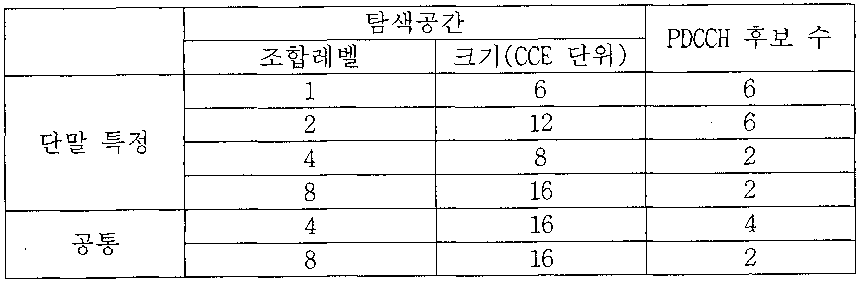
특정한 PDCCH를 위해 필요한 CCE의 개수는 제어정보의 크기인 DCI 페이로드, 셀 대역폭, 채널 부호화율 등에 따라 달라진다. 구체적으로 특정한 PDCCH를 위한 CCE의 개수는 다음 표 1과 같이 PDCCH 포맷에 따라 정의될 수 있다. ' 【표 1】
Figure imgf000013_0001
PDCCH는 네 가지 포맷 중 어느 하나의 포맷이 사용될 수 있는데, 이는 단말에게 알려지지 않는다.따라서 단말의 입장에서는 PDCCH포맷을 알지 못한 채 디코딩을 수행하여야 하는데, 이를 블라인드 디코딩이라 한다. 다만, 단말이 하향링크에 사용되는 가능한 모든 CCE를 각 PDCCH 포맷에 대하여 디코딩하는 것은 큰 부담이 되므로, 스케줄러에 대한 제약과 디코딩 시도 흿수를 고려하여 탐색공간 (Search Space)이 정의된다.
즉, 탐색공간은 조합레벨 (Aggregation Level) 상에서 단말이 디코딩을 시도해야 하는 CCE들로 이루어진 후보 PDCCH의 조합이다. 여기서 조합레벨 및 PDCCH후보의 수는 다음 표 2와 같이 정의될 수 있다.
【표 2】
Figure imgf000014_0001
상기 표 2에서 알 수 있듯이 4가지의 조합레벨이 존재하므로, 단말은 각 조합레벨에'따라 복수개의 탐색공간을 갖게 된다. 또한, 표 2에서 나타내는 바와 같이 탐색공간은 단말 -특정 탐색공간과 공통 탐색공간으로 구분될 수 있다. 단말 -특정 탐색공간은 특정한 단말들을 위한 것으로서 각 단말은 단말 -특정 탐색공간을 모니터링 (가능한 DCI포떳에 따라 PDCCH후보의 조합에 대해 디코딩을 시도하는 것)하여 PDCCH에 마스킹되어 있는 RNTI 및 CRC를 확인하여 유효하면 제어정보를 획득할 수 있다.
공통 탐색공간은 시스템 정보에 대한 동적 스케줄링이나 페이징 메시지 등 복수개의 단말 또는 모든 단말들이 PDCCH를 수신해야 할 필요가 있는 경우를 위한 것이다. 다만, 공통 탐색공간은 자원 운용상 특정 단말을 위한 것으로 사용될 수도 있다. 또한, 공통 탐색공간은 단말 -특정 탐색공간과 오버램될 수도 있다.
상술한 바와 같이 단말은 탐색공간에 대해 디코딩을 시도하는데, 이 디코딩 시도의 흿수는 DCI포맷 및 RRC시그널링을 통해 결정되는 전송모드 (Transmission mode)로 결정된다. 반송파 병합 (Carrier Aggregation;^ 적용되지 않는 경우, 단말은 공통 탐색공간에 대해 PDCCH 후보 6개 각각에 대해 두 가지의 DCI 크기 (DCI 포맷 0/1A/3/3A 및 DCI 포맷 1C)를 고려하여야 하므로 최대 12번의 디코딩 시도가 필요하다. 단말 특정 탐색공간에 대해서는, PDCCH후보수 (6 + 6 + 2 + 2 = 16) 에 대해 두 가지의 DCI 크기를 고려하므로 최대 32번의 디코딩 시도가 필요하다. 따라서 반송파 병합이 적용되지 않는 경우 최대 44회의 디코딩 시도가 필요하다.
개선된 (Enhanced) 제어채널
개선된 제어 채널의 일례로서, E-PDCCH(Enhanced-PDCCH)에 대해서 설명한다. 앞서 설명된 DCI 포맷들에 포함된 제어정보들은 LTE/LTE-A에 정의된 PDCCH를 통해 전송되는 것을 위주로 설명되었으나, PDCCH가 아닌 다른 하향링크 제어 채널 , 예를 들어, E-PDCCH(Enhanced PDCCH)에 적용이 가능하다. E-PDCCH는 단말을 위한 스케줄링 할당 등의 DCI를 나르는 (carry) 제어 채널의 새로운 형태에 해당하고ᅳ셀간 간섭 조정 (ICIC), CoMP, ΜΙΗΠΜ0등의 기법을 효과적으로 지원하기 위하여 도입될 수 있다.
이러한 E-PDCCH는 기존 LTE/LTE-A 시스템에서 PDCCH 전송을 위해 정의되는 영역 (예를 들어, 도 3 의 제어 영역)을 제외한 시간-주파수 자원영역 (예를 들어, 도 3의 데이터 영역)에 할당된다는 점에서 기존의 PDCCH와 구별된다 (이하에서는 기존의 PDCCH를 E-PDCCH와 구분하기 위해, 레거시 -PDCCH(legacy-PDCCH)라 칭한다) . 예를 들어, E-PDCCH의 자원 요소 매핑은, 시간 영역에서는 하향링크 서브프레임의 처음 N (예를 들어, N≤4)개의 OFDM 심볼을 제외한 OFDM 심볼에 매핑되고 주파수 영역에서는 반-정적으로 할당된 자원블록 (RB)의 세트에 매핑되는 것으로 표현할 수 있다.
또한, E-PDCCH가 도입되는 이유와 유사하게, 상향링크 전송에 대한 HARQ ACK/NACK 정보를 나르는 새로운 제어 채널로서 E-PHICH가 정의될 수 있고, 하향링크 제어 채널 전송에 사용되는 자원 영역에 대한 정보를 나르는 새로운 제어 채널로서 E-PCFICH가 정의될 수도 있다. 이러한 E-PDCCH, E-PHICH 및 /또는 E-PCFICH를 통칭하여 Enhanced-제어채널이라고 칭할 수 있다.
EREG(Enhanced REG)는 Enhanced-제어채널들의 자원 요소에의 매핑을 정의하기 위해 사용될 수 있다. 예를 들어 , 하나의 물리자원블록쌍 (PRB pair)에 대해서, 16개의 EREG들 (즉, EREG 0부터 EREG 15)이 존재할 수 있다. 하나의 PRB 상에서 DMRS(DeModulation Reference Signal)가 매핑된 RE들을 제외한 나머지 RE들에 대해서 0부터 15까지 번호가 매겨진다. 번호가 매겨지는 순서는 먼저 주파수가 증가하는 순서에 따르고 그 후 시간이 증가하는 순서에 따른다. 예를 들어, i 라는 번호가 매겨진 RE들이 하나의 EREG i를 구성한다.
Enhanced-제어 채널은 하나 또는 복수개의 ECCE(En anced CCE)들의 조합 (aggregation)을 사용하여 전송될 수 있다. 각각의 ECCE는 하나 또는 복수개의 EREG를 포함할 수 있다ᅳ ECCE당 EREG의 개수는, 예를 들어, 4또는 8일 수 있다 (일반 CP의 일반서브프레임의 경우에는 4).
Enhanced-제어 채널에 대해 이용가능한 ECCE들은 0부터 NECCE-1까지 번호 매겨질 수 있다. NECCE의 값은, 예를 들어., 1, 2, 4, 8, 16또는 32일 수 있다.
Enhanced-제어 채널의 전송을 위해 설정된 PRB 쌍의 RE들의 개수는 다음의 조건들 i), ϋ) 및 iii)을 만족하는 RE들의 개수로 정의될 수 있다. i) PRB쌍의 16개의 EREG들 중의 하나의 일부일 것, i i ) CRS(Cel 1-speci f i c Reference Signal ) 또는 CS I -RS (Channel State Information-Reference Signal)를 위해 사용되지 않을 것, 및 iii) Enhancedᅳ제어 채널이 시작되는 OFDM 심블의 인덱스 이상의 OFDM 심볼에 속할 것. ,
또한, Enhanced-제어 채널은 로컬 (localized) 방식 또는 분산 (distr ibuted) 방식으로 RE들에 매핑될 수 있다. Enhanced-제어 채널은, 다음의 조건들 a) 내지 d)를 만족하는 RE들에 매핑될 수 있다. a)전송을 위해 할당된 EREG의 일부일 것, b) 물리브로드캐스트채널 (Physical Broadcast Channel; PBCH) 또는 동기 신호 (synchronization signal)의 전송에 이용되는 PRB 쌍의 일부가 아닐 것, c) CRS또는 특정 UE에 대한 CSI-RS를 위해 사용되지 않을 것, 및 d) Enhanced—제어 채널이 시작되는 OFDM심볼의 인덱스 이상의 OFDM심볼에 속할 것.
Enhanced-제어 채널의 할당은 다음과 같이 수행될 수 있다. 기지국으로부터의 상위 계층 시그널링을 통해서 단말에게 하나 또는 복수개의 Enhanced-제어 채널ᅳ PRB-세트를 설정하여 즐 수 있다. 예를 들어, E-PDCCH의 경우에는 Enhanced-제어 채널 -PRB—세트는 E— PDCCH의 모니터링을 위한 것일 수 있다.
또한, Enhanced-제어 채널의 RE 매핑에는 크로스 인터리빙 (cross interleaving)이 적용되거나 적용되지 않을 수 있다.
크로스 인터리빙이 적용되지 않는 경우, 하나의 Enhancedᅳ제어 채널은 자원블록의 특정 세트에 매핑될 수 있으며, 자원블록의 세트를 구성하는 자원블록들의 개수는 조합레벨 (aggregation level) 1, 2, 4 또는 8에 대응할 수 있다. 또한, 다른 Enhanced-제어 채널이 해당 자원블록 세트에서 전송되지 않는다.
크로스 인터리빙이 적용되는 경우, 복수개의 Enhanced-제어 채널들이 함께 다중화 및 인터리빙되어, Enhanced-제어 채널 전송을 위해 할당된 자원블록 상에 매핑될 수 있다. 즉, 특정 자원블록 세트 상에서 복수개의 Enhanced-제어 채널이 함께 매핑되는 것으로 표현할 수도 있다.
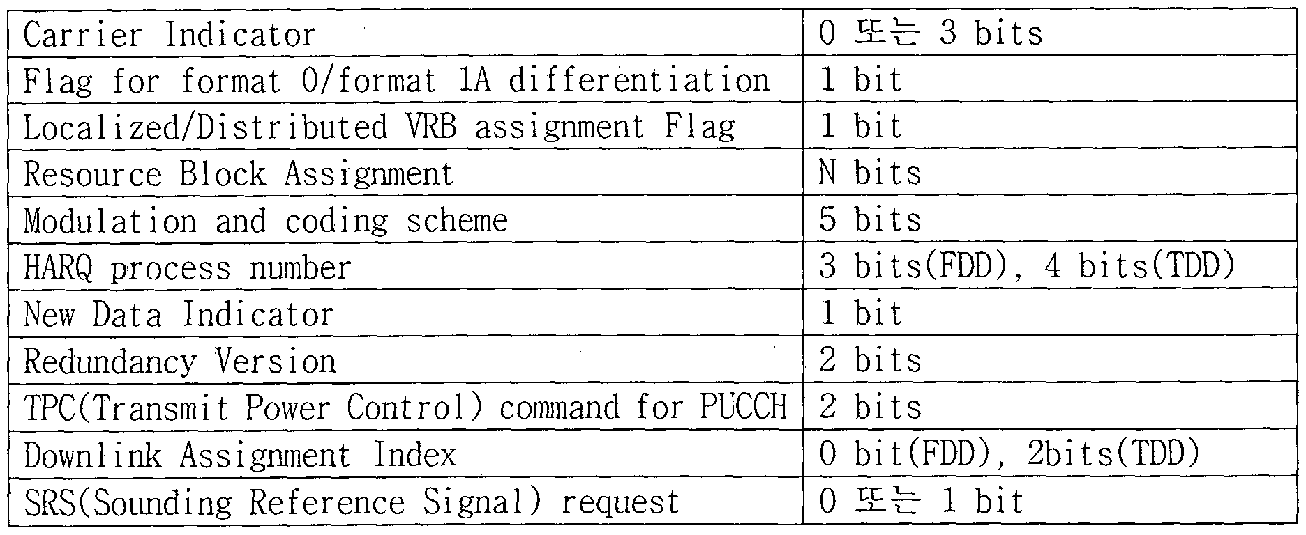
DCI 포맷 1A
DCI 포맷 1A는 하나의 셀에서의 하나의 PDSCH 코드워드의 콤팩트 (compact) 스케줄링을 위해서 사용되는 DCI 포맷을 지칭한다. 즉, DCI 포맷 1A 는 단일 안테나 전송, 단일 스트림 전송, 또는 전송 다이버시티 전송 등 랭크 1 전송에서 사용되는 제어 정보들을 포함할 수 있다. 표 3 및 표 4는 기존의 3GPP LTE/LTE-A 표준에서 정의하는 DCI 포맷 1A의 일례를 나타낸다.
【표 3]
Figure imgf000017_0002
상기 표 1과 같은 제어 정보를 포함하는 DCI포맷
Figure imgf000017_0001
통하여 기지국으로부터 단말에게 제공될 수 있다. DCI 포맷 1A는 가장 기본적인 하향링크 전송 (탱크 1으로 하나의 PDSCH 코드워드 전송)을 스케즐링하는 정보를 포함한다. 따라서, 탱크 2 이상 및 /또는 복수개의 코드워드 전송 등의 복잡한 PDSCH 전송 방식이 을바르게 수행되지 않는 경우, 가장 기본적인 PDSCH 전송 방식을 지원하기 위한 용도 (즉, 폴백 (fallback)) 용도로 사용될 수 있다.
상향링크 서브프레임 구조
도 4는 상향링크 서브프레임의 구조를 나타내는 도면이다. 상향링크 서브프레임은 주파수 영역에서 제어 영역과 데이터 영역으로 분할될 수 있다. 제어 영역에는 상향링크 제어 정보를 포함하는 물리상향링크제어채널 (Physical Uplink Control Channel; PUCCH)이 할당된다. 데이터 영역에는 사용자 데이터를 포함하는 물리상향링크공유채널 (Physical uplink shared channel; PUSCH)이 할당된다. 단일 반송파 특성을 유지하기 위해서, 하나의 단말은 PUCCH와 PUSCH를 동시에 전송하지 않는다. 하나의 단말에 대한 PUCCH는 서브프레임에서 자원블특 쌍 (RB pair)에 할당된다. 자원블록 쌍에 속하는 자원블록들은 2 슬롯에 대하여 상이한 부반송파를 차지한다. 이를 PUCCH에 할당되는 자원블록 쌍이 슬롯 경계에서 주파수 -호핑 (frequency-hopped)된다고 한다.
참조 신호 (Reference Signal; RS)
무선 통신 시스템에서 패킷을 전송할 때, 전송되는 패킷은 무선 채널을 통해서 전송되기 때문에 전송과정에서 신호의 왜곡이 발생할 수 있다. 왜곡된 신호를 수신측에서 을바로 수신하기 위해서는 채널 정보를 이용하여 수신 신호에서 왜곡을 보정하여야 한다. 채널 정보를 알아내기 위해서, 송신측과 수신측에서 모두 알고 있는 신호를 전송하여, 상기 신호가 채널을 통해 수신될 때의 왜곡 정도를 가지고 채널 정보를 알아내는 방법을 주로 사용한다. 상기 신호를 파일럿 신호 (Pilot Signal) 또는 참조 신호 (Reference Signal)라고 한다.
다중안테나를 사용하여 데이터를 송수신하는 경우에는 각 송신 안테나와 수신 안테나 사이의 채널 상황을 알아야 올바른 신호를 수신할 수 있다. 따라서, 각 송신 안테나 별로 별도의 참조 신호가 존재하여야 한다.
하향링크 참조신호는 셀 내의 모든 단말이 공유하는 공용 참조신호 (Co纖 on Reference Signal; CRS)와 특정 단말만을 위한 전용 참조신호 (Dedicated Reference Signal; DRS)가 있다. 이러한 참조신호들에 의해 채널 추정 및 복조를 위한 정보가 제공될 수 있다.
수신측 (단말)은 CRS로부터 채널의 상태를 추정하여 CQI (Channel Quality Indicator), PMKPrecoding Matrix Index) 및 /또는 RI(Rank Indicator)와 같은 채널 품질과 관련된 지시자를 송신측 (기지국)으로 피드백할 수 있다. CRS는 셀 -특정 (cell-specific) 참조신호라 불릴 수도 있다. 또는 CQI/PMI/RI 와 같은 채널 상태 정보 (Channel State Information; CSI)의 피드백과 관련된 RS를 별도로 CSI-RS로 정의할 수도 있다.
한편, DRS는 PDSCH 상의 데이터의 복조가 필요한 경우에 해당 RE를 통하여 전송될 수 있다. 단말은 상위계층으로부터 DRS의 존재 여부에 대하여 지시받을 수 있고, 해당 PDSCH가 매핑된 경우에만 DRS가 유효하다는 것에 대하여 지시받을 수 있다. DRS는 단말 -특정 (UE-specific) 참조신호 또는 복조용 참조신호 (Demodulation Reference Signal; DMRS)라 불릴 수도 있다.
도 5는 기존의 3GPP LTE 시스템 (예를 들어, 릴리즈 -8)에서 정의하는 CRS 및
DRS가 하향링크 자원블록 쌍 (RBpair)상에 메핑되는 패턴을 나타내는 도면이다. 참조신호가 매핑되는 단위로서의 하향링크 자원블록 쌍은 시간 상으로 하나의 서브프레임 X주파수 상으로 12 부반송파의 단위로 표현될 수 있다. 즉, 하나의 자원블록 쌍은 시간 상으로 일반 CP의 경우에는 14 개의 OFDM 심볼 길이, 확장된 CP의 경우에는 12 개의 OFDM 심볼 길이를 가진다. 도 5는 일반 CP의 경우의 자원블록 쌍을 나타낸다.
도 5는 기지국이 4 개의 전송 안테나를 지원하는 시스템에서 참조신호의 자원블록 쌍 상에서의 위치를 나타낸다. 도 5에서 'R0' , 'Rl' , 'R2' 및 'R3'로 표시된 자원 요소 (RE)는, 각각 안테나 포트 인덱스 0, 1, 2 및 3에 대한 CRS의 위치를 나타낸다. 한편, 도 5에서 'D'로 표시된 자원 요소는 DRS의 위치를 나타낸다.
이하에서는 CRS에 대하여 구체적으로 설명한다.
CRS는 물리 안테나단의 채널을 추정하기 위해 사용되며, 셀 내에 있는 모든 단말 (UE)들이 공통적으로 수신할 수 있는 참조신호로서, 전대역에 걸쳐 분포한다. CRS는 채널 상태 정보 (CSI) 획득 및 데이터 복조의 목적으로사용될 수 있다.
CRS는 송신측 (기지국)의 안테나 구성에 따라 다양한 형태로 정의된다. 3GPP LTE (예를 들어, 릴리즈 -8) 시스템은 다양한 안테나 구성 (Antenna configuration)을 지원하며, 하향링크 신호 송신측 (기지국)은 단일 안테나, 2 전송 안테나, 4 전송 안테나 등 3 종류의 안테나 구성을 가진다. 기지국이 단일 안테나 전송을 하는 경우에는 단일 안테나 포트를 위한 참조신호가 배치된다. 기지국이 2 안테나 전송을 하는 경우에는 2개의 안테나 포트를 위한 참조신호가 시간분할다중화 (Time Division Multiplexing) 및 /또는 주파수분할다중화 (Frequency Division Multiplexing) 방식으로 배치된다. 즉, 2 개의 안테나 포트를 위한 참조신호가 상이한 시간 자원 및 /또는 상이한 주파수 자원에 배치되어 서로 구별될 수 있다. 또한, 기지국이 4 안테나 전송을 하는 경우에는 4개의 안테나 포트를 위한 참조신호가 TDM/FDM 방식으로 배치된다. CRS를 통해 하향링크 신호 수신측 (단말)에 의하여 추정된 채널 정보는 단일 안테나 전송 (Single Antenna Transmission),전송 다이버시티 (Transmit diversity), 폐 -루프 공간 다중화 (Closed-loop Spatial multiplexing), 개 -루프 공간 다중화 (Open-loop Spatial multiplexing), 다중사용자 (Multi User; MU)-MIMO(Multiple Input Multiple Output) 등의 전송 기법으로 송신된 데이터의 복조를 위해 사용될 수 있다.
다중 안테나를 지원하는 경우, 어떤 안테나 포트에서 참조신호를 전송할 때에 참조신호 패턴에 따라 지정된 자원요소 (RE) 위치에 참조신호를 전송하고, 다른 안테나 포트를 위해 지정된 자원요소 (RE) 위치에는 어떠한 신호도 전송하지 않는다.
CRS가자원 블록 상에 매큉되는 규칙은 아래의 수학식 1에 따른다.
【수학식 11 k = 6m + (v + vshlft )mod 6
Figure imgf000021_0001
vshlft= e11扁 d6
수학식 1에서, k는 부반송파 인덱스이고, /은 심볼 인덱스이며, p는 안테나 포트 인텍스이다.
Figure imgf000021_0002
하나의 하향링크 슬롯의 OFDM 심볼의 개수이고,
N DL n
는 하향링크에 할당된 자원블록의 개수 o 는 슬롯 인덱스이고,
N cell
ID 셀 ID를 의미한다. mod 는 모듈러 연산을 의미한다. 주파수 영역에서 참조신호의 위치는 Vshiit 값에 의존한다. Vshiit 값은 또한 셀 ID에 의존하므로, 참조신호의 위치는 샐 별로 상이한 주파수 시프트 값올 가지게 된다.
구체적으로는, CRS를 통한 채널 추정 성능을 높이기 위해 셀 별로 CRS의 주파수 영역 상의 위치를 시프트 (shift)시켜 다르게 할 수 있다. 예를 들어, 참조신호가 3 부반송파 마다 위치하는 경우에 , 어떤 샐은 3k 의 부반송파 상에 , 다른 셀은 3k+l의 부반송파 상에 배치 되도록 할 수 있다. 하나의 안테나 포트의 관점에서 참조신호는 주파수 영역에서 6 RE 간격 (즉, 6 부반송파 간격)으로 배치되고, 다른 안테나 포트를 위한 참조신호가 배치되는 RE 와는 주파수 영역에서 3 RE간격을 유지한다 .
또한, CRS에 대해서 전력 부스팅 (power boosting)이 적용될 수 있다. 전력 부스팅이란,하나의 OFDM심볼의 자원요소 (RE)들 중 참조신호를 위해 할당된 RE가 아닌 다른 RE로부터 전력을 가져와서 참조신호를 보다 높은 전력으로 전송하는 것을 의미한다.
시간 영역에서 참조신호 위치는 각 슬롯의 심볼 인덱스 (/) 0을 시작점으로 하여 일정한 간격으로 배치된다: 시간 간격은 CP 길이에 따라 다르게 정의된다ᅳ 일반 CP경우는 슬롯의 심볼 인텍스 0및 4에 위치하며, 확장된 CP경우는 슬롯의 심볼 인덱스 0및 3에 위치한다. 하나의 OFDM심볼에는 최대 2개의 안테나 포트를 참조신호만이 정의된다. 따라서 4 전송 안테나 전송 시, 안테나 포트 0 및 1을 위한 참조신호는 슬롯의 심볼 인덱스 0및 4 (확장된 CP경우는 심볼 인덱스 0및 3)에 위치하며, 안테나 포트 2 및 3을 위한 참조신호는 슬롯의 심볼 인덱스 1에 위치한다. 단, 안테나 포트 2 및 3을 위한 참조신호의 주파수 위치는 2 번째 슬롯에서는 서로 스위칭된다.
이하에서는 DRS에 대하여 구체적으로 설명한다.
DRS (또는 단말 -특정 참조신호)는 데이터 복조를 위해 사용되는 참조신호로, 다중안테나 전송을 할 때 특정 단말에 사용되는 프리코딩 가중치를 참조신호에도 그대로 사용함으로써 단말이 참조신호를 수신했을 때에 각 송신안테나에서 전송되는 프리코딩 가중치와 전송 채널이 결합된 균등 채널 (Equivalent channel)을 추정할 수 있도록 한다.
기존의 3GPP LTE시스템 (예를 들어, 릴리즈 -8)은 최대 4송신 안테나 전송을 지원하고, 탱크 1 범포밍을 위한 DRS가 정의되어 있다. 탱크 1 범포밍올 위한 DRS는 안테나 포트 인덱스 5 에 대한. 참조신호로 표시되기도 한다. DRS가 자원블록 상에 매핑되는 규칙은 아래의 수학식 2에 따른다. 수학식 2는 일반 CP의 경우에 대한 것이다.
【수학식 2]
Figure imgf000023_0001
:¾ ©: 職' vshlft = ^ID11励 d3
수학식 2에서, k는 부반송파 인덱스이고, /은 심볼 인덱스이며, 는 안테나 포트 인텍스이다. 수 영역에서 자원 블록 크기를 나타내며
Figure imgf000023_0002
N PDSH 부반송파의 개수로 는 물리자원블록 넘버를 나타낸다 R
n
대웅하는 PDSCH전송의 자원 블록의 대역폭을 나타낸다. 슬롯 인덱스이고,
Ν cell
ID 셀 ID를 의미한다. mod 는 모들러 연산을 의미한다. 주파수 영역에서 참조신호의 위치는 Vshift 값에 의존한다. Vshift 값은 또한 셀 ID에 의존하므로, 참조신호의 위치는 셀 별로 상이한 주파수 시프트 값을 가지게 된다.
한편, 3GPP LTE의 진화인 LTE-A(Advanced) 시스템에서는 높은 차수 (order)의
MIM0, 다중-셀 전송, 발전된 MU-MIM0등이 고려되고 있는데, 효율적인 참조신호의 운용과 발전된 전송 방식을 지원하기 위하여 DRS기반의 데이터 복조를 고려하고 있다. 즉, 기존의 3GPP LTE (예를 들어, 릴리즈—8) 에서 정의하는 탱크 1빔포밍을 위한 DRS (안테나 포트 인덱스 5)와는 별도로, 추가된 안테나를 통한 데이터 전송을 지원하기 위하여 2 이상의 레이어에 대한 DRS (또는 단말 -특정 참조신호 또는 DMRS)를 정의할 수 있다.
도 6은 LTE— A 시스템에서 정의되는 MRS 패턴의 일례를 나타내는 도면이다. 도 6에서는 하향링크 데이터가 전송되는 하나의 자원블록 쌍 (일반 CP 의 경우, 시간 상으로 14 개의 OFDM 심볼 X 주파수 상으로 12 부반송파) 상에서 DMRS가 전송되는 자원요소의 위치를 나타낸다. DMRS 는 LTE-A 시스템에서 추가적으로 정의되는 8 개의 안테나 포트 (안테나 포트 인덱스 7 내지 14)에 대하여 전송될 수 있다. 서로 다른 안테나 포트에 대한 DMRS 는 상이한 주파수 자원 (부반송파) 및 /또는 상이한 시간 자원 (OFDM 심볼)에 위치하는 것으로 구분될 수 있다 (즉, FDM 및 /또는 TDM 방식으로 다중화될 수 있다). 또한, 동일한 시간-주파수 자원 상에 .위치하는 서로 다른 안테나 포트에 대한 DMRS 들은 서로 직교 코드 (orthogonal code)에 의해서 구분될 수 있다 (즉, CDM방식으로 다중화될 수 있다).
한편, 발전된 무선 통신 시스템 (예를 들어, LTE-A 시스템)에서는 새로운 안테나 포트를 위한 채널 상태 정보 (CSI) 측정을 위한 별도의 참조신호 (CSI-RS)가 정의된다.
도 7은 LTE-A 시스템에서 정의되는 CSI-RS 패턴의 예시들을 나타내는 도면이다. 도 7에서는 하향링크 데이터가 전송되는 하나의 자원블록 쌍 (일반 CP 의 경우, 시간 상으로 14 개의 OFDM 심볼 X 주파수 상으로 12 부반송파) 상에서 CSI-RS 가 전송되는 자원요소의 위치를 나타낸다. 어떤 하향링크 서브프레임에서 도 7(a) 내지 7(e) 증 하나의 CSI-RS 패턴이 이용될 수 있다. CSI-RS 는 LTE-A 시스템에서 추가적으로 정의되는 8개의 안테나 포트 (안테나 포트 인덱스 15내지 22) 에 대하여 전송될 수 있다. 서로 다른 안테나 포트에 대한 CSI-RS 는 상이한 주파수 자원 (부반송파) 및 /또는 상이한 시간 자원 (OFDM 심볼)에 위치하는 것으로 구분될 수 있다 (즉, FDM 및 /또는 TDM 방식으로 다중화될 수 있다). 또한, 동일한 시간-주파수 자원 상에 위치하는 서로 다른 안테나 포트에 대한 CSI— RS 들은 서로 직교 코드 (orthogonal code)에 의해서 구분될 수 있다 (즉, CDM 방식으로 다중화될 수 있다). 도 7(a)의 예시에서 CSI— RS CDM 그룹 1 로 표시된 자원요소 (RE)들에는 안테나 포트 15및 16에 대한 CSI— RS들이 위치할 수 있고, 이들은 직교 코드에 의해 다중화될 수 있다.도 7(a)의 예시에서 CSI— RSCDM그룹 2로 표시된 자원요소들에는 안테나 포트 17및 18에 대한 CSI— RS들이 위치할 수 있고, 이들은 직교 코드에 의해 다중화될 수 있다. 도 7(a) 의 예시에서 CSI-RS CDM그룹 3으로 표시된 자원요소들에는 안테나 포트 19및 20에 대한 CSI— RS들어 위치할 수 있고, 이들은 직교 코드에 의해 다중화될 수 있다. 도 7(a) 의 예시에서 CSI— RS CDM 그룹 4 로 표시된 자원요소들에는 안테나 포트 21 및 22 에 대한 CSI-RS 들이 위치할 수 있고, 이들은 직교 코드에 의해 다중화될 수 있다. 도 7(a)를 기준으로 설명한 동일한 원리가 도 7(b) 내지 7(e)에 적용될 수 있다. 도 5 내지 7 의 RS 패턴들은 단지 예시적인 것이며, 본 발명의 다양한 실시예들을 적용함에 있어서 특정 RS패턴에 한정되는 것이 아니다.즉,도 5내지 7 과 다른 RS 패턴이 정의 및 사용되는 경우에도 본 발명의 다양한 실시예들은 동일하게 적용될 수 있다.
반송파 병합
도 8은 반송파 병합을 설명하기 위한 도면이다. 반송파 병합을 설명하기에 앞서 LTE-A에서 무선자원을 관리하기 위해 도입된 셀 (Cell)의 개념에 대해 먼저 설명한다. 셀은 하향링크 자원과 상향링크 자원의 조합으로 이해될 수 있다. 여기서 상향링크 자원은 필수 요소는 아니며 따라서 셀은 하향링크 자원 단독 또는 하향링크 자원과 상향링크 자원으로 이루어질 수 있다. 다만, 이는 현재 LTE-A 릴리즈 10에서의 정의이며 반대의 경우, 즉 셀이 상향링크 자원 단독으로 이루어지는 것도 가능하다. 하향링크 자원은 하향링크 구성반송파 (Downlink component carrier, DL CC)로 상향링크 자원은 상향링크 구성반송파 (Uplink component carrier, UL CC)로 지칭될 수 있다. DL CC 및 UL CC는 반송파 주파수 (carrier frequency)로 표현될 수 있으며, 반송파 주파수는 해당 셀에서의 중심주파수 (center frequency)를 의미한다.
셀은 프라이머리 주파수 (primary frequency)에서 동작하는 프라이머리 셀 (primary cell, PCell)과 세컨더리 주파수 (secondary frequency)에서 동작하는 세컨더리 셀 (secondary cell, SCell)로 분류될 수 있다. PCell과 SCell은 서빙 셀 (serving cell)로 통칭될 수 있다. PCell은 단말이 초기 연결 설정 (initial connection establishment) 과정을 수행하거나 연결 재설정 과정 또는 핸드오버 과정에서 지시된 셀이 PCell이 될 수 있다. 즉, PCell은 후술할 반송파 병합 환경에서 제어관련 중심이 되는 셀로 이해될 수 있다. 단말은 자신의 PCell에서 PUCCH를 할당 받고 전송할 수 있다. SCell은 RRC(Radio Resource Control) 연결 설정이 이루어진 이후 구성 가능하고 추가적인 무선 자원을 제공하는데 사용될 수 있다. 반송파 병합 환경에서 PCell을 제외한 나머지 서빙 셀을 SCell로 볼 수 있다. RRC— CONNECTED 상태에 있지만 반송파 병합이 설정되지 않았거나 반송파 병합을 지원하지 않는 단말의 경우, PCell로만 구성된 서빙 셀이 단 하나 존재한다. 반면, RRCJ30NNECTED상태에 있고 반송파 병합이 설정된 단말의 경우, 하나 이상의 서빙 셀이 존재하고, 전체 서빙 셀에는 PCell과 전체 SCell이 포함된다. 반송파 병합을 지원하는 단말을 위해 네트워크는 초기 보안 활성화 (initial security activation) 과정이 개시된 이후, 연결 설정 과정에서 초기에 구성되는 PCell에 부가하여 하나 이상의 SCell을 구성할수 있다.
이하, 도 8을 참조하여 반송파 병합에 대해 설명한다. 반송파 병합은 높은 고속 전송를에 대한 요구에 부합하기 위해 보다 넓은 대역을 사용할 수 있도록 도입된 기술이다ᅳ 반송파 병합은 반송파 주파수가 서로 다른 2개 이상의 구성반송파 (component carrier, CC)들 또는 2 개 이상의 셀들의 병합 (aggregation)으로 정의될 수 있다. 도 8을 참조하면, 도 8(a)는 기존 LTE 시스템에서 하나의 CC를 사용하는 경우의 서브프레임을 나타내고, 도 8(b)는 반송파 병합이 사용되는 경우의 서브프레임을 나타낸다. 도 8(b)에는 예시적으로 20MHz의 (X 3개가 사용되어 총 60MHz의 대역폭을 지원하는 것을 도시하고 있다. 여기서 각 CC는 연속적일 수도 있고, 또한 비 연속적일 수도 있다.
단말은 하향링크 데이터를 복수개의 DL CC를 통해 동시에 수신하고 모니터링할 수 있다. 각 DL CC와 UL CC사이의 링키지 (linkage)는 시스템 정보에 의해 지시될 수 있다. DLCC/ULCC링크는 시스템에 고정되어 있거나 반ᅳ정적으로 구성될 수 있다.또한, 시스템 전체 대역이 N개의 CC로 구성되더라도 특정 단말이 모니터링 /수신할 수 있는 주파수 대역은 M(<N)개의 CC로 한정될 수 있다. 캐리어 병합에 대한 다양한 파라미터는 셀 특정 (cell-specific), 단말 그룹 특정 (UE group-specific) 또는 단말 특정 (UE— speci f ic) 방식으로 설정될 수 있다.
도 9는 크로스—반송파 스케줄링을 설명하기 위한 도면이다..크로스-반송파 스케줄링이란, 예를 들어, 복수의 서빙 셀 중 어느 하나의 DL CC의 제어영역에 다른 DL CC의 하향링크 스케줄링 할당 정보를 모두 포함하는 것, 또는 복수의 서빙 셀 중 어느 하나의 DLCC의 제어영역에 그 DLCC와 링크되어 있는 복수의 UL CC에 대한 상향링크 스케줄링 승인 정보를 모두 포함하는 것을 의미한다.
이하에서는 반송파 지시자 필드 (carrier indicator field, CIF)에 대해 설명한다.
CIF는 앞서 설명된 바와 같이 PDCCH를 통해 전송되는 DCI 포맷에 포함되거나 (예를 들어, 3 비트 크기로 정의됨) 또는 포함되지 않을 수 있으며 (예를 들어, 0 비트 크기로 정의됨), 포함된 경우 크로스 반송파 스케줄링이 적용된 것을 나타낸다. 크로스 반송파 스케즐링이 적용되지 않은 경우에는 하향링크 스케줄링 할당 정보는 현재 하향링크 스케줄링 할당 정보가 전송되는 DL CC상에서 유효하다. 또한 상향링크 스케줄링 승인은 하향링크 스케줄링 할당 정보가 전송되는 DL CC 와 링크된 하나의 UL CC에 대해 유효하다.
크로스 반송파 스케즐링이 적용된 경우, CIF는 어느 하나의 DL CC에서 PDCCH를 통해 전송되는 하향링크 스케줄링 할당 정보에 관련된 CC를 지시한다. 예를 들어, 도 9를 참조하면 DL CC A상의 제어 영역 내 PDCCH를 통해 DL CC B및 DL CC C에 대한 하향링크 할당 정보, 즉 PDSCH 자원에 대한 정보가 전송된다. 단말은 DLCCA를 모니터링하여 CIF를 통해 PDSCH의 자원영역 및 해당 CC를 알 수 있다.
PDCCH에 CIF가 포함되거나 또는 포함되지 않는지는 반-정적으로 설정될 수 있고, 상위 계층 시그널링에 의해서 단말-특정으로 활성화될 수 있다.
CIF가 비활성화 (disabled)된 경우에, 특정 DL CC 상의 PDCCH는 해당 동일한 DL CC상의 PDSCH자원을 할당하고, 특정 DL CC에 링크된 UL CC상의 PUSCH자원을 할당할 수 있다. 이 경우, 기존의 PDCCH구조와 동일한 코딩 방식, CCE기반 자원 매핑, DCI 포맷 등이 적용될 수 있다.
한편, CIF가 활성화 (enabled)되는 경우에, 특정 DL CC상의 PDCCH는 복수개의 병합된 CC들 중에서 CIF가 지시하는 하나의 DL/UL CC 상에서의 PDSCH/PUSCH 자원을 할당할 수 있다. 이 경우, 기존의 PDCCH DCI 포맷에 CIF가 추가적으로 정의될 수 있으며, 고정된 3비트 길이의 필드로 정의되거나, CIF위치가 DCI포맷 크기에 무관하게 고정될 수도 있다. 이 경우에도, 기존의 PDCCH 구조와 동일한 코딩 방식 , CCE 기반 자원 매핑, DCI 포맷 등이 적용될 수 있다.
CIF가 존재하는 경우에도, 기지국은 PDCCH를 모니터링할 DLCC세트를 할당할 수 있다. 이에 따라, 단말의 블라인드 디코딩의 부담아 감소할 수 있다. PDCCH 모니터링 CC 세트는 전체 병합된 DL CC의 일부분이고 단말은 PDCCH의 검출 /디코딩을 해당 CC 세트에서만 수행할 수 있다. 즉, 단말에 대해서 PDSCH/PUSCH를 스케줄링하기 위해서, 기지국은 PDCCH를 PDCCH 모니터링 CC 세트 상에서만 전송할 수 있다. PDCCH 모니터링 DL CC 세트는 단말—특정 또는 단말 그룹ᅳ특정 또는 셀ᅳ특정으로 설정될 수 있다. 예를 들어,도 9의 예시에서와 같이 3 개의 DL CC가 병합되는 경우에, DL CC A 가 PDCCH 모니터링 DL CC로 설정될 수 있다. CIF가 비활성화되는 경우, 각각의 DL CC 상의 PDCCH는 DL CC A에서의 PDSCH만을 스케줄링할 수 있다. 한편, CIF가 활성화되면 DL CC A상의 PDCCH는 DL CC A는 물론 다른 DL CC에서의 PDSCH 도 스케줄링할 수 았다. DL CC A가 PDCCH 모니터링 CC로 설정되는 설정되는 경우에는 DL CC B 및 DL CC C 에는 PDCCH가 전송되지 않을 수 있다.
협력형 다중-포인트 (Cooperative Multi-Point; CoMP)
3GPP LTE-A 시스템의 개선된 시스템 성능 요구조건에 따라서, CoMP 송수신 기술 (co— MIM0, 공동 (collaborative) MIM0또는 네트워크 MIM0등으로 표현되기도 함)이 제안되고 있다. CoMP 기술은 셀 -경계 (cell-edge)에 위치한 단말의 성능을 증가시키고 평균 섹터 수율 (throughput)을 증가시킬 수 있다.
일반적으로, 주파수 재사용 인자 (frequency reuse factor)가 1 인 다중-셀 환경에서, 셀-간 간섭 (Inter— Cell Interference; ICI)으로 인하여 셀-경계에 위치한 단말의 성능과 평균 섹터 수율이 감소될 수 있다. 이러한 ICI를 저감하기 위하여, 기존의 LTE 시스템에서는 단말 특정 전력 제어를 통한 부분 주파수 재사용 (fractional frequency reuse; FFR)과 같은 단순한 수동적인 기법을 이용하여 간섭에 의해 제한을 받은 환경에서 셀-경계에 위치한 단말이 적절한 수율 성능을 가지도록 하는 방법이 적용되었다. 그러나, 셀 당 주파수 자원 사용을 낮추기보다는, ICI를 저감하거나 ICI를 단말이 원하는 신호로 재사용하는 것이 보다 바람직할 수 있다. 위와 같은 목적을 달성하기 위하여, CoMP 전송 기법이 적용될 수 있다.
하향링크의 경우에 적용될 수 있는 CoMP 기법은 크게 조인트-프로세성 (joint processing; JP) 기법 및 조정 스케줄링 /범포밍 (coordinated scheduling/beamforming; CS/CB) 기법으로 분류할 수 있다.
JP 기법은 CoMP 협력 단위의 각각의 포인트 (기지국)에서 데이터를 이용할 수 있다. CoMP협력 단위는 협력 전송 기법에 이용되는 기지국들의 집합을 의미한다. JP 기법은 조인트 전송 (Joint Transmission) 기법과 동적 셀 선택 (Dynamic cell selection) 기법으로 분류할 수 있다.
조인트 전송 기법은, PDSCH 가 한번에 복수개의 포인트 (CoMP 협력 단위의 일부 또는 전부)로부터 전송되는 기법을 말한다. 즉, 단일 단말로 전송되는 데이터는 복수개의 전송 포인트로부터 동시에 전송될 수 있다. 조인트 전송 기법에 의하면, 코히어런트하게 (coherently) 또는 년-코히어런트하게 (non-coherent ly) 수신 신호의 품질이 향상될 수 있고, 또한, 다른 단말에 대한 간섭을 능동적으로 소거할 수도 있다.
동적 셀 선택 기법은, PDSCH가 한번에 (CoMP 협력 단위의) 하나의 포인트로부터 전송되는 기법을 말한다. 즉, 특정 시점에서 단일 단말로 전송되는 데이터는 하나의 포인트로부터 전송되고, 그 시점에 협력 단위 내의 다른 포인트는 해당 단말에 대하여 데이터 전송을 하지 않으며, 해당 단말로 데이터를 전송하는 포인트는 동적으로 선택될 수 있다.
한편, CS/CB 기법에 의하면 CoMP 협력 단위들이 단일 단말에 대한 데이터 전송의 빔포밍을 협력적으로 수행할 수 있다. 여기서, 데이터는 서빙 셀에서만 전송되지만, 사용자 스케줄링 /범포밍은 해당 CoMP 협력 단위의 셀들의 조정에 의하여 결정될 수 있다.
한편, 상향링크의 경우에, 조정 (coordinated)다중-포인트 수신은 지리적으로 떨어진 복수개의 포인트들의 조정에 의해서 전송된 신호를 수신하는 것을 의미한다. 상향링크의 경우에 적용될 수 있는 CoMP 기법은 조인트 수신 (Joint Reception; JR) 및 조정 스케줄링 /빔포밍 (coordinated scheduling/beamforming; CS/CB)으로 분류할 수 있다.
JR 기법은 PUSCH 를 통해 전송된 신호가 복수개의 수신 포인트에서 수신되는 것을 의미하고, CS/CB 기법은 PUSCH 가 하나의 포인트에서만 수신되지만 사용자 스케줄링 /빔포밍은 CoMP 협력 단위의 셀들의 조정에 의해 결정되는 것을 의미한다. 다중 셀 환경에서 물리 채널 수신 방안
전술한 바와 같은 CoMP 동작 및 /또는 반송파 병합이 적용되는 무선 통신 시스템올 다중 셀 시스템 또는 다중 셀 환경이라고 칭할 수 있다. 단말이 물리 채널을 수신하고 올바르게 복조하기 위해서는, 해당 물리 채널에 적용되는 여러 가지 속성 (예를 들어, 자원 할당, 관련된 참조 신호 , 전송 타이밍, 전송 전력, 스크램블링 정보 등)에 대한 올바른 가정에 기초하여야 한다. 특히, 다중 셀 환경에서 복수개의 셀이 협력하여 물리 채널을 전송한다는 점에서, 기존의 단일 셀 환경에서 단말이 물리 채널의 수신을 위해 적용하는 물리 채널에 대한 가정이 그대로 적용될 수 없다.
본 발명에서는 다중 셀 환경에서 전송되는 물리 채널을 단말이 을바르게 수신할 수 있도록 하는 방안에 대해서 제안한다.구체적으로,본 발명에서는 다중 셀 환경에서 전송되는 물리 채널의 속성에 대해서 단말이 결정 /가정하는 구체적인 방안 /규칙에 대해서 제안한다.
실시예 1
본 실시예 1은 다중 셀 환경에서 전송되는 물리 채널의 자원 매핑 위치 관련 정보를 네트워크가 시그널링하는 방안에 대한 것이다. 예를 들어, 다증 셀 환경에서 전송되는 물리 채널의 자원 매큉 위치 관련 정보에 기초하여, 단말은 상기 물리 채널을 수신 또는 복조하는 데에 필요한 참조신호 (예를 들어, CRS) 위치에 대한 가정과 자원요소 (RE) 매핑 방식을 결정할 수 있다.
도 10은 다중 샐 환경에서 단말이 2 개의 전송 포인트 (TP)로부터의 하향링크 신호를 수신하는 동작을 예시적으로 나타내는 도면이다.
도 10의 예시에서는 전송 포인트 0 및 1이 CoMP 동작을 통하여 CoMP UE에게 하향링크 신호를 전송할 수 있고, CoMP UE는 하향링크 채널에 대한 채널상태정보 (CSI) 피드백을 전송 포인트 0에게 보고하는 동작을 나타낸다.
도 10의 예시는 반송파 병합 기술의 관점에서도 설명될 수 있다. 예를 들어, 전송 포인트 0및 1은 반송파 병합에서의 PCell 및 SCell 에 각각 해당할 수 있고, 상기 복수개의 셀 (즉, Pceli 및 SCell)에 걸쳐서 CoMP 동작을 수행하는 UE에게 반송파 병합이 설정되는 것으로 표현될 수도 있다. 이 경우, 상기 UE에 대한 PDCCH는 PCell로 지정된 셀로부터 전송될 수 있고 상기 UE에 대한 PDSCH는 PCell 및 SCell의 협력 (예를 들어, 조인트 전송 또는 동적 셀 선택 등)에 의해 전송될 수 있다.
또한, 도 10의 예시에서의 상기 전송 포인트 0 및 1은 단말에 대한 서빙 셀 (serving cell) 및 이웃 셀 (neighbor ing cell)이라고 표현될 수도 있다. 구체적으로, UE에 대한 PDCCH가 전송되고, 상기 UE의 기본적인 측정 (예를 들어, RRM(Radio Resource Management )/RLM( Radio Link Monitoring) '측정) 및 다양한 보고의 대상이 되는 셀을 서빙 셀이라고 표현할 수 있다. 이 경우, 서빙 셀과 이웃 셀의 협력에 의해 전송되는 PDSCH에 대한 스케줄링 정보는 상기 서빙 셀 상에서 전송되는 PDCCH로부터 획득될 수 있다. 즉, 상기 서빙 셀은, 단말에 대한 스케줄링 정보가 전송되는 전송 포인트라고도 표현할 수 있다.
이하의 설명에서는 상기 전송 포인트 0, PCell 및 서빙 셀을 통칭하여 PCell이라고 하고, 상기 전송 포인트 1, SCell 및 이웃 샐을 통칭하여 SCell이라고 한다.
SCell은 독자적으로 PDSCH 스케즐링을 수행하지는 않기 때문에, PCell 상의 PDCCH가 SCell이 참여하는 PDSCH에 대한 스케줄링을, 크로스-반송파 스케줄링의 방식으로 수행한다고 해석할 수도 있다. 다만, CoMP 동작에서는 기존의 반송파 병합에서와는 달리 복수개의 셀들 (PCell 및 SCelK들))의 각각이 동일한 반송파 주파수 상에 위치하므로, 실제로는 하나의 동일한 반송파 주파수 상에서 복수개의 셀들이 전송에 참여하는 형태로 볼 수 있고, 이 경우에는 CIF(carrier indicator field)는' PDSCH가 전송되는 반송파 주파수를 지시하는 것이 아니라, PDSCH 전송에 참여하는 셀이 무엇인지를 지시하는 정보로서 해석 또는 활용될 수 있다. 또한, 일반적으로 하나의 주파수 반송파 상에서는 하나의 PDSCH만이 전송되므로, )MP UE에 대한 PDCCH 탐색 공간은 PCell 상에서만 활성화 (activate)되고 SCell 상에서 탐색 공간은 활성화 (activate)되지 않을 수도 있다. 이 경우, PCell 상의 PDSCH 전송, SCell 상의 PDSCH 전송, PCell과 SCell이 함께 참여하는 PDSCH 전송의 경우를 포함하는 모든 PDSCH 전송에 대한 스케줄링 정보가 PCell 상의 탐색 공간 상에서 전송되는 PDCCH를 통하여 제공될 수 있다. 즉, CoMP UE는 PCell 상의 탐색 공간 상에서만 PDCCH (또는 E-PDCCH) 블라인드 디코딩을 수행하지만, SCell 상의 탐색 공간 상에서는 PDCCH (또는 E-PDCCH) 블라인드 디코딩을 수행하지 않을 수 있다.
예를 들어, CoMP동작 중에서 동적 셀 선택 (또는 동적 포인트 선택)의 경우에, 네트워크는 PCell의 PDCCH를 이용하여 PDSCH를 스케줄링하되, CIF를 이용하여 어떤 셀이 해당 PDSCH를 전송하는지를 지시할 수 있다. 예를 들어, 특정 SCell에서의 전송이 CIF에 의해서 지시되었다면, 단말은 해당 SCell의 CRS 위치에는 PDSCH가 매핑되지 않는다고 가정하고 상기 PDSCH를 복조할 수 있다. 동일한 의미를 달리 표현하자면, 특정 자원요소 위치를 제외한 자원요소 상에 PDSCH가 매핑되는 것을 PDSCH의 레이트 매칭 (rate matching)이라고 하면, 단말은 CIF에 의해 지시되는 샐 상에서의 PDSCH 레이트 매칭 패턴을 유추하고 이에 기초하여, 해당 셀에서 전송되는 PDSCH의 복조를 수행할 수 있다.
기존의 CIF는 하나의 셀을 지시하므로, 특정 시점에서 PDSCH 전송에 하나의 셀만이 관여하는 동적 셀 선택의 경우에는 적절하게 이용될 수 있다. 그러나, 두 개 이상의 샐이 동시에 PDSCH를 전송하는 조인트 전송 (JT)의 경우에는 PDSCH 전송에 참여하는 셀들이 무엇인지를 기존의 CIF를 단순히 재사용하여서는 표현할 수가 없다. 즉, 기존의 CIF를 그대로 사용하면, CoMP JT 방식으로 전송되는 PDSCH에 관여하는 셀들이 무엇인지를 단말에게 알려줄 수 없다. 또한, 단말은 복수개의 셀로부터 전송되는 PDSCH의 복조를 위해서, 복수개의 샐의 각각에 대해서 CRS의 위치 (즉, PDSCH가 매핑되지 않는 자원요소 위치)를 결정하고 PDSCH 레이트 매칭 패턴을 결정하여야 하는데, 어떤 샐에서 PDSCH가 전송되는지를 알 수 없기 때문에 어떤 셀의 CRS 위치를 고려해야 하는 것인지 올바르게 결정할 수 없다ᅳ
따라서, 본 발명에서는 CIF의 일부 상태 (state)를 "복수개의 샐이 PDSCH 전송에 참여한다' '는 사실을 알리는 것으로 정의하는 것을 제안한다. 예를 들어, CIF는 3 비트 크기로 구성되고, 반송파 병합에서는 최대 5개의 반송파에 대한 크로스-반송파 스케줄링을 지원하는 것으로 가정한다. 이 경우, 크로스-반송파 스케줄링이 적용되는 대상 샐을 알려주기 위해서 최대 5 개의 상태 (예를 들어, 000, 001, 010, 011, 100)가 필요하고, 나머지 3개의 상태 (예를 들어, 101, 110, 111)은 본 발명에서 제안하는 복수개의 셀이 PDSCH 전송에 참여한다는 사실을 알려주는 것으로 정의할 수 있다. 예를 들어, CIF 상태가 101이면 PCell과 제 1 SCeU이, CIF 상태가 110이면 PCell과 제 2 SCell이, CIF 상태가 111이면 제 1 SCell과 제 2 SCell이 PDSCH의 JT에 참여한다는 사실을 알리는 용도로 사용할 수 있다. 이러한 CIF를 수정된 CIF라고 칭할 수 있다. 수정된 CIF의 상태와 전송 참여 셀들을 지시하는 내용의 매핑관계는, 사전에 정해져 있올 수도 있고, 또는 보다 유연한 동작을 지원하기 위하여 네트워크가 상위 계층 신호 (예를 들어, RRC 시그널링)을 통하여 설정하여 즐 수도 있다.
본 발명에서 제안하는 수정된 CIF를 수신한 UE는, 수정된 CIF에 의해 지시되는 샐 (들)의 각각이 CRS를 전송하는 RE에는 PDSCH가 매핑되지 않는다는 가정하에 해당 PDSCH복조를 수행할 수 있다. 즉, 단말은 수정된 CIF로부터 PDSCH 전송에 참여하는 각각의 셀에서의 PDSCH 레이트 매칭 패턴을 결정할 수 있다. 이러한 관점에서 본 발명에서 제안하는 수정된 CIF는 DSCH 복조에 있어서 가정해야 할 CRS 위치를 알리는 정보' '로서 해석될 수도 있다. 이러한 해석이 적용되는 경우에는 수정된 CIF가 해당 서브프레임에서의 CRS위치에 대한 정보를 직접적으로 제공하는 것으로 구성될 수도 있다. 예를 들어, 기존의 CIF가 단순히 특정 셀을 지시하는 것에 그친다면, 본 발명에서 제안하는 수정된 CIF는 특정 셀 (또는 셀들의 세트)의 CRS의 Vshift 값 및 /또는 CRS 포트 개수를 직접적으로 지시하도록 구성될 수도 있다. 또는 수정된 CIF가 기존의 CIF의 일부 상태를 이용하여 구성될 수도 있지만, 기존의 CIF와 별도의 지시자로서 구성되어 CRS 위치를 알려줄 수도 있다.
따라서, 본 발명에서 제안하는 수정된 CIF는, 어떤 셀 (들)이 PDSCH 전송에 참여하는지를 알려주는 정보 및 /또는 해당 참여 셀 (들)의 각각에서의 PDSCH 레이트 매칭 패턴을 알려주는 정보로서 구성될 수 있다. 또한 본 발명에서 제안하는 수정된 CIF는, 그 용어 자체의 직접적인 의미에 제한되지 않고, 본 발명에서 제안하는 내용을 포함하는 정보로서의 의미를 가진다.
실시예 2
본 실시예 2는 다중 셀 환경에서 전송되는 물리 채널에 적용되는 스크램블링 시퀀스를 결정하는 방안에 대한 것이다.
물리채널 전송에 있어서 간섭 제거를 위해 변조 단계 전에 단말-특정의 스크램블링 시뭔스에 의해 전송 비트들에 대한 스크램블링이 수행될 수 있다. 이러한 스크램블링 시¾스의 시드 (seed) 값은 샐 ID에 기초하여 결정된다. 다중 셀 환경에서 전송되는 PDSCH에 대한 스크램블링 시뭔스 역시 PDSCH를 전송하는 셀의 셀 ID에 의해서 결정된다. 따라서, 다중 셀 환경에서 전송되는 PDSCH를 단말이 올바르게 수신할 수 있게 하기 위해서는, 상기 단말이 해당 PDSCH의 스크램블링 시퀀스를 결정하는 할 수 있도록 해야 한다. 상가 수정된 CIF의 경우에는 PDSCH 전송에 참여하는 특정 셀 (또는 샐들의 세트)을 알려주는 것에 그치므로, 어떤 해당 PDSCH에 적용되는 스크램블링 시퀀스에 적용되는 셀 ID가 어떤 셀의 것인지를 단말이 결정할 수 있도록 해야 한다.
따라서, 본 발명에서는 상기 제안한 수정된 CIF를 이용하는 방안과 함께 또는 별도로, PDSCH 스크램블링 시퀀스에 적용되는 시드 값 (예를 들어, 셀 ID)을 결정하는 규칙으로서 이하의 방안들을 제안한다.
첫 번째 방안으로서, PDSCH 스크램블링 시¾스는 항상 PCell의 셀 ID에 기초하껴 결정되는 것으로 정의할 수 있다. - 두 번째 방안으로서, 복수개의 셀이 PDSCH 전송에 참여하는 것으로 지시된 경우에는 PCell의 샐 ID에 기초하여, 하나의 셀이 PDSCH 전송에 참여하는 것으로 지시된 경우에는 해당 하나의 셀의 셀 ID에 기초하여 PDSCH 스크램블링 시퀀스가 결정되는 것으로 정의할 수 있다.
세 번째 방안으로서, PDSCH 스크램블링 시퀀스에 적용되는 셀 ID에 우선순위를 정할 수 있다. 예를 들어, PDSCH의 전송에 실제로 참여하는 셀 (들) 중에서 최상위의 우선순위를 가지는 셀의 셀 ID가 PDSCH 스크램블링 시퀀스에 적용될 수 있다. 예를 들어, PDSCH스크램블링 시뭔스에 관련된 셀의 우선순위는, PCell > 제 1 SCell > 제 2 SCell > . . ᅳ의 순서로 미리 정해질 수 있다.
상기 방안들 중 하나에 따른 규칙이 네트워크와 단말 간에 공유될 수 있다. 이에 따라, 기지국은 상기 규칙 중 하나에 따라 스크램블링 시퀀스를 생성하여 PDSCH 전송에 적용할 수 있고, 단말은 기지국이 적용한 규칙과 동일한 규칙에 따라 PDSCH 스크램블링 시퀀스를 결정하여 해당 PDSCH를 올바르게 수신 /복조할 수 있다.
실시예 3
본 실시예 3은 다중 셀 환경에서 전송되는 물리 채널의 복조에 관련된 참조신호의 시뭔스를 결정하는 방안에 대한 것이다.
PDSCH의 복조와 관련된 참조신호 (즉, DMRS 또는 단말 -특정 참조신호)는 셀 ID를 시드 값으로 하여 생성된 소정의 의사 랜덤 시퀀스 (pseudo random sequence)가 이용된다. 기존의 무선 통신 시스템에서 하나의 셀이 PDSCH를 전송하는 경우에는 DMRS시퀀스 생성의 시드 값이 명확하게 결정되지만,복수개의 셀이 PDSCH 전송에 참여하는 경우에는 어떤 셀의 셀 ID를 기반으로 해당 PDSCH에 관련된 DMRS의 시퀀스를 생성해야 하는 것인지가 정해져 있지 않다.
따라서, 본 발명에서는 상기 제안한 수정된 CIF를 이용하는 방안과 함께 또는 별도로, 네트워크가 단말에게 DMRS 시뭔스에 적용되는 시드 값 (예를 들어, 셀 ID, 또는 시퀀스 생성에 이용되는 다른 값)을 알려주는 방안을 제안한다. 네트워크는 상위계층 산호 (예를 들어, RC 시그널링)을 통해서 복수개의 셀이 PDSCH 전송에 참여하는 경우에, 해당 PDSCH에 관련된 DMRS 시퀀스의 생성에 사용하는 시드 값을 샐 세트 별로 미리 알려줄 수 있다. 예를 들에 본 발명에서 제안하는 수정된 CIF에 의해서 PDSCH 전송에 참여하는 셀들이 지시되는 경우, 해당 셀들로 구성된 셀 세트에 대응하는 DMRS 시뭔스 생성 시드 값을 결정하고, 결정된 시드 값에 의해서 DMRS 시.퀀스가 생성된 것으로 가정하여 DMRS 검출 및 PDSCH복조를 수행할 수 있다.
예를 들어, PCell, 제 1 SCell 및 제 2 SCell이 CoMP에 참여하는 잠정적인 셀들로 지정된 경우, 네트워크는 상위 계층 신호를 통해서 셀 세트 별로 대해서 사용되는 DMRS의 시드 값으로서 가상 (virtual) 셀 ID를 단말에게 알려줄 수 있다. 예를 들어, PCell 및 제 1 SCell의 세트의 경우에는 가상 셀 ID a가, PCell 및 제 2 SCell의 세트의 경우에는 가상 셀 ID b가, 제 1 SCell 및 제 2 SCell의 세트의 경우에는 가상 셀 ID c가, PCell, 제 1 SCell 제 2 SCell 모두로 구성된 세트의 경우에는 가상 셀 ID d가 DMRS 시퀀스 생성에 이용되는 것으로 알려즐 수 있다. 여기서 가상 셀 ID a, b, c 및 d는 임의의 셀 ID이거나, 셀 ID와 동일한 (또는 유사한) 형태를 가지는 일련의 숫자일 수 있고ᅳ 일부는 중복될 수 있다.
실시예 4
본 실시예 4는 MBSFN(Multi cast-Broadcast Single Frequency Network) 서브프레임을 고려한 상기 수정된 CIF의 구성 및 해석 방안에 대한 것이다. MBSFN 서브프레임은 제어 영역 (도 3 참조)에서는 CRS 및 PDCCH 등이 전송되지만, 데이터 영역에서는 아무런 신호가 전송되지 않는 것 (예를 들어, 적어도 CRS 및 PDSCH가 전송되지 않는 것)으로 설정되는 서브프레임을 의미한다. 어떤 셀의 MBSFN 설정 (또는 MBSFN 패턴)에 대한 정보는 시스템 정보 블록 (SIB)올 통하여 단말에게 미리 제공될 수 있다.
상기 수정된 CIF가 DSCH 복조에 있어서 가정해야 할 CRS 위치를 알리는 필드"로서 사용되는 경우에, 상기 수정된 CIF에 의해 지시되는 셀 (또는 샐 세트)은, 실제로 PDSCH 전송 동작을 수행하는 셀 (또는 샐 세트)과는 상이할 수 있다. 예를 들어, PCell 및 제 1 SCell이 DMRS를 이용하여 CoMP JT를 수행하는 경우에, 제 1 SCell이 특정 서브프레임을 MBSFN 서브프레임으로 설정하는 것을 가정하면,해당서브프레임에서는 PCell의 CRS만이 데이터 영역에 존재하게 된다. 이 경우, 제 1 SCell이 MBSFN 서브프레임으로 설정한 서브프레임에서의 CRS 오버헤드 (즉, CRS가 차지하는 자원요소 또는 그 개수)를 단말이 올바르게 가정할 수 있도록, 네트워크는 PCell이 단독으로 PDSCH를 전송하는 경우와 동일하게 상기 수정된 CIF를 설정할 수 있다. 이에 따라, 단말은 제 1 SCell이 MBSFN 서브프레임으로 설정한 서브프레임에서 전송되는 PDSCH에 대한 스케줄링 정보를 포함하는 PDCCH DCI 내의 상기 수정된 CIF가 지시하는 대로 PCell의 CRS 만이 존재하는 것으로 가정하여 상기 PDSCH의 레이트 매칭 패턴을 올바르게 결정할 수 있다.
또는, 제 1 SCell이 MBSFN 서브프레임으로 설정한 서브프레임에서 스케줄링되는 PDSCH에 대해서, PCell과 제 1 SCell이 함께 전송에 참여하는 것으로 단말에게 지시되는 경우 (즉, 상기 수정된 CIF가 PCell 및 제 1 SCell 모두의 CRS의 위치를 지시하는 경우)라고 하더라도, 해당 단말에게는 제 1 SCell이 MBSFN으로 설정한 서브프레임이 무엇인지에 대한 정보가 SIB를 통하여 이미 전달되어 있으므로, 단말은 PCell 만의 CRS가 데이터 영역에 존재하는 것을 유추 및 가정하여 이에 따라 PDSCH 레이트 매칭 패턴을 올바르게 결정할 수 있다.
실시예 5
본 실시예 5는 본 발명에서 제안하는 수정된 CIF에 의해 단말에게 제공된 정보를 단말이 활용하는 방안에 대한 것이다.
일례로서, 단말의 간섭 측정에 상기 수정된 CIF에 의해 지시되는 정보가 유리하게 활용될 수 있다. 예를 들어, 상기 수정된 CIF에 의해서 PCell과 제 1 SCell이 함께 PDSCH를 전송하는 것으로 지시된 경우에는, 단말은 PCeU과 제 1 SCell의 CRS RE에서 각 셀의 CRS를 제거한 후에, 해당 RE에서 관측되는 간섭은 PCeU과 제 1 SCell을 제외한 나머지 셀들로부터의 간섭에 해당한다는 사실을 추정할 수 있다. 이를 바탕으로 PCeU과 제 1 SCeU이 JT를 수행할 경우의 CSI를 보다 정확하게 추정하여 네트워크로 보고하는 것이 가능하다.
다른 일례로서, 단말은 상기 수정된 CIF에 의해 지시되는 CRS 위치에 대한 정보가, PDSCH에만 유효하고 PDCCH에는 유효하지 않은 것으로 가정할 수 있다.즉, PDSCH에 대해서는 전술한 바와 같이 복수개의 셀의 CRS 위치를 고려하여 (예를 들어, 복수개의 셀 모두의 CRS위치를 고려하거나, 일부 셀에서 MBSFN으로 설정한 서브프레임에서는 해당 셀의 CRS 위치는 고려하지 않고) PDSCH 복조를 수행할 수 있다. 그러나, PDCCH는 항상 PCeU 상에서만 전송되므로, 단말은 PCel'l의 CRS만이 존재하는 것으로 가정하여 (즉, SCeU의 CRS RE에는 PDCCH가 존재하는 것으로 가정하여) PDCCH를 복조할 수 있다.
도 11은 본 발명에 따른 물리 채널 조에 이용되는 CRS 오버헤드를 설명하기 위한 도면이다.
도 11의 예시에서는 PCell (도 11에서 (P)로 표현)과 제 1 SCeU (도 11에서 (S1)으로 표현)이 각각 4 개의 CRS 포트 (즉, 안테나 포트 0, 1, 2, 3)를 가지고, PCell 및 제 1 SCell 모두가 일반 서브프레임으로 설정한 (즉, 비 -MBSFN 서브프레임으로 설정한) 서브프레임이고, Vshift 값은 PCell과 제 1 SCell에서 1 부반송파 만큼 차이를 가지는 경우를 가정한다.
도 11(a)는 PDSCH를 제 1 SCelK도 11에서 S1으로 도시함) 흔자서 전송하는 경우의 예시이다. 도 11(a)에서 도시하는 바와 같이 , PDCCH가 전송되는 OFDM심볼. 0및 1에 해당하는 영역에서는 PCell의 CRS (R0(P), R1(P), R2(P) 및 R3(P)) 만이 존재하고, PDSCH가 전송되는 OFDM심볼 2내지 13에 해당하는 영역에서는 PCell은 PDSCH 전송에 참여하지 않으므로 제 1 SCell의 CRS (R0(S1), Rl(Sl), R2(S1) 및 R3(SD) 만이 존재한다. 이 경우, 단말에 대해 제공되는 상기 수정된 CIF 정보가 "PDSCH복조에 있어서 가정해야 할 CRS위치"로서 제 ISCell의 CRS위치를 알려줄 수 있다. 단말은 이러한 수정된 CIF 정보는 PDSCH 복조에만 적용되고, PDCCH 복조에는 적용되지 않는 것으로 해석한다. 즉, 단말은 PDCCH를 복조할 때에는 PCell의 CRS RE를 제외하고 나머지 RE들에는 모두 PDCCH가 존재하는 것을 가정할 수 있고, PDSCH를 복조할 때에는 제 1 SCell의 CRS RE를 제외하고 나머지 RE들에는 모두 PDSCH가 존재하는 것으로 가정할 수 있다.
도 11(b)는 PDSCH를 PCell과 제 1 SCell이 함께 전송하는 경우에 대한 CRS 오버해드의 예시이다. 도 1Kb)에서 도시하는 바와 같이, PDCCH가 전송되는 OFDM 심볼 0및 1에 해당하는 영역에서는 PCell의 CRS (R0(P), R1(P), R2(P) 및 R3(P)) 만이 존재하고, PDSCH가 전송되는 OFDM 심볼 2 내지 13에 해당하는 영역에서는 PCell의 CRS (R0(P), R1(P), R2(P) 및 R3(P)) 및 SCell의 CRS (R0(S1), R1(S1), R2(S1)및 R3(S1))가 모두 존재한다. 이 경우,단말에 대해 제공되는 상기 수정된 CIF정보가 "PDSCH복조에 있어서 가정해야 할 CRS위치"로서 PCell의 CRS위치 및 제 ISCell의 CRS위치를 알려줄 수 있다.단말은 이러한 수정된 CIF정보는 PDSCH 복조에만 적용되고, PDCCH 복조에는 적용되지 않는 것으로 해석한다. 즉 단말은 PDCCH를 복조할 때에는 PCell의 CRS RE를 제외하고 나머지 RE들에는 모두 PDCCH가 존재하는 것을 가정할 수 있고, PDSCH를 복조할 때에는 PCell의 CRS RE와 제 1 SCell의 CRS RE를 제외하고 나머지 RE들에는 모두 PDSCH가존재하는 것으로 가정할 수 있다.
실시예 6
본 실시예 6은 PDSCH 복조에 이용되는 참조 신호를 결정하는 방안에 대한 것이다.
PDSCH가 단일 샐에 의해 전송되는 기존의 무선 통신 시스템에서는, 기본적으로 DMRS (또는 단말 -특정 RS)를 기반으로 PDSCH를 복조하도록 설정되어 있는 하향링크 전송 모드 (예를 들어, 전송 모드 9)에서, 폴백 (fallback) 용도의 DCI 포맷 1A를 이용하여 PDSCH가 스케줄링될 수 있다. DCI 포맷 1A를 이용하여 스케줄링된 PDSCH에 대해서, CRS가 존재하는 비 -MBSFN 서브프레임에서는 CRS를 이용하여 상기 PDSCH를 복조하고, PDSCH 영역에 CRS가 존재하지 않는 MBSFN 서브프레임에서는 CRS가 아닌 DMRS를 이용하여 복조하는 것이 바람직하다. 그러나,상기 설명한 바와 같이 PDSCH전송에 참여하는 셀이 동적으로 변하는 경우에、는, PDSCH의 복조에 이용되는 참조신호를 결정함에 있어서 불명료성이 존재할 수 있다. 예를 들어, PCell 입장에서는 MBSFN서브프레임이지만 제 ISCell 입장에서는 비 -MBSFN 서브프레임인 특정 서브프레임에서, 제 1 SCell에서만 PDSCH가 전송된다는 사실을 DCI 포맷 1A에 포함된 CIF (또는 상기 수정된 CIF)를 통하여 단말에게 전달하는 경우를 가정할 수 있다. 이를 수신한 단말은 해당 서브프레임을 MBSFN서브프레임으로 보고 DMRS를 이용하여 PDSCH복조를 수행할지 아니면 비 -MBSFN 서브프레임으로 보고 CRS를 이용하여 PDSCH 복조를 수행할지를 명확하게 결정할 수 없다.
본 발명에서는 이러한 불명료성을 해소하기 위해서, 단말이 PDSCH 복조에 사용할 참조신호를 결정하는 방안들에 대해서 제안한다.
첫 번째 방안으로서, PCell의 MBSFN 서브프레임 설정에 따라서 PDSCH 복조에 사용할 참조신호가 결정될 수 있다. 즉, PCell의 MBSFN서브프레임에서는 DMRS를 사용하고, PCell의 비 -MBSFN 서브프레임에서는 CRS를 사용하는 것으로 규칙을 정의할 수 있다. 이 방안에 따르면, 단말이 사용하는 참조신호의 결정 기준이 PCell로 고정되므로, 다중 셀 환경에서 각각의 셀의 MBSFN 설정의 변화에 의한 영향이 상대적으로 적다는 점에서 유리하다. 만약 어떤 서브프레임의 PCell의 MBSFN서브프레임이면서 제 ISCell의 비 -MBSFN서브프레임인 경우에,상기 수정된 CIF에 의해 PDSCH복조에 있어서 가정해야 할 CRS위치로서 제 ISCell의 CRSRE가 지시되는 경우에,단말은 PDSCH복조 자체는 DMRS를 이용하면서,제 ISCell의 CRS RE에는 해당 PDSCH가 매핑되지 않는 것으로 가정하고 PDSCH 복조를 수행해야 한다. '
두 번째 방안으로서, PDSCH를 전송하는 셀의 MBSFN서브프레임 설정에 따라서 PDSCH 복조에 사용할 참조신호가 결정될 수 있다. 예를 들어, 만약 어떤 서브프레임의 PCell의 MBSFN 서브프레임이면서 제 1 SCell의 비 -MBSFN 서브프레임인 경우에, CIF (또는 상기 수정된 CIF)에 의해서 PDSCH 전송이 제 1 SCell에서만 수행된다고 지시될 수 있다. 이 경우에, 단말은 상기 PDSCH가 전송되는 서브프레임이 제 1 SCell의 MBSFN 서브프레임이면 DMRS를 사용하고, 제 1 SCeU의 비 -MBSFN 서브프레임이면 CRS를 사용하여 상기 PDSCH의 복조를 수행할 수 있다. 이 방안에 따르면, 실제로 PDSCH를 전송하는 셀의 MBSFN 서브프레임 설정에 따라서 PDSCH 복조에 이용될 참조신호가 결정되므로, 보다 유연하게 참조신호가 결정된다는 점에서 유리하다.
상기 방안들과 관련하여, 두 개 이상의 셀이 전송에 참여하는 경우에는 각 셀에 우선 순위를 부여하고, 실제 전송에 참여한 셀 중 최상위의 우선 순위를 가지는 셀의 MBSFN 서브프레임 설정에 따라서 PDSCH 복조에 사용될 참조신호를 결정할 수도 있다. 즉, 최상위의 우선순위를 가지는 셀의 MBSFN서브프레임에서는 DMRS를 사용하고, 최상위의 우선순위를 가지는 샐의 비— MBSFN 서브프레임에서는 CRS를 사용하여 PDSCH 복조가 수행될 수 있다. 이러한 우선 순위는 예를 들어 PCell > 제 1 SCell > 제 2 SCell > ... 의 순서로 미리 정해질 수 있다.
상기 방안들과 관련하여, CIF (또는 상기 수정된 CIF)가 실제로 PDSCH 전송에 참여하는 셀 (들)을 알려주도록 설정된 상황에서는, DCI포맷 1A에 CIF를 포함하지 않고, DCI 포맷 1A는 항상 PCell만이 전송에 참여하는 PDSCH를 스케줄링하는 것으로 규정할 수도 있다. 이는, 상기 첫 번째 내지 세 번째 방안과 같은 참조신호 결정 동작의 복잡성을 방지하는 점에서 유리하게 이용될 수 있으몌 특히 DCI포맷 1A의 비트 슷자를 줄일 수 있으므로 PDCCH다코딩 에러를 줄이는데 효과적일 수 있다.
예를 들어, 상기 첫 번째 방안이 적용되는 경우에는, PCelK또는 PDSCH를 스케줄링하는 서빙 셀)의 MBSFN 서브프레임에서는 SCell (또는 PDSCH를 스케줄링하지 않는 셀) 역시 DMRS를 사용하여 PDSCH의 전송을 수행할 수 있으므로, 상기 수정된 CIF (또는 PDSCH 복조에 있어서 가정해야 할 CRS 위치를 알려주는 정보)를 사용하여 PDSCH를 전송할 수 있다. 그러나, 상기 첫 번째 방안이 적용되는 경우에는, PCell의 비 -MBSFN 서브프레임에서는 PCell의 CRS를 사용하여 PDSCH 전송이 수행되어야 하므로, SCell은 PDSCH 전송에 참여할 수가 없게 된다.
따라서, 상기 첫 번째 방안이 적용되는 경우라면 PCell (또는 PDSCH를 스케즐링하는 서빙 셀)의 관점에서 MBSFN 서브프레임이 아닌 서브프레임에서는 상기 CIF (또는 PDSCH 복조에 있어서 가정해야 할 CRS 위치를 알려주는 정보)가 DCI에 추가되지 않도록 동작할 수 있다. 또는, 상기 첫 번째 방안이 적용되는 경우에 PCell (또는 PDSCH를 스케줄링하는 서빙 셀)의 비 -MBSFN서브프레임에서는, PDSCH 복조에 있어서 가정해야 할 CRS 위치를 알려주는 정보가 단말에게 시그널링되더라도, 시그널링된 CRS 위치는 무시하고 상기 PCell의 CRS 위치를 가정하여 상기 PDSCH를 복조할수 있다.
실시예 7
본 실시예 7은 E-PDCCH의 복조를 위한 E-PDCCH 자원 할당의 가정 (또는 E-PDCCH 레이트 매칭 패턴에 대한 가정)을 결정하는 방안에 대한 것이다.
PDSCH 스케줄링 정보 등을 포함하는 DCI는, 전술한 바와 같이 하향링크 서브프레임의 데이터 영역 (도 3 참조)에서 DMRS (또는 단말 -특정 참조신호)를 이용하여 전송되는 E-PDCCH를 통해서도 쟌송될 수 있다. 이러한 E-PDCCH를 복조하기 위해서 E-PDCCH의 자원 할당에 대한 올바른 가정이 필요하다. 종래 기술에서는 이에 대한 방안이 마련되어 있지 않으므로, 본 발명에서는 다중 셀 환경에서 E-PDCCH가 전송되는 경우에 E-PDCCH의 자원 할당에 대한 가정을 결정하는 방안들을 제안한다.
첫 번째 방안으로서, 단말은 PCell의 CRS 오버헤드만을 고려하여 E-PDCCH가 할당되는 것으로 가정할 수 있다. 예를 들어, 복수개의 셀이 CoMP 동작을 수행하는 경우에도, 단말은 PCell의 CRS RE 위치만을 제외하고 E-PDCCH가 매핑되는 것으로 가정하고 (즉,다른 샐의 CRSRE에는 E-PDCCH가존재하는 것으로 가정하여) E-PDCCH 복조를 수행할 수 있다. 이는, E— PDCCH 레이트 매칭 패턴의 결정의 복잡도를 줄이는 측면에서 유리하게 이용될 수 있다.
두 번째 방안으로서, 단말은 CoMP에 참여할 가능성이 있는 모든 셀들의 CRS 오버해드를 고려하여 E— PDCCH가 할당되는 것으로 가정할 수 있다. 예를 들어, 복수개의 셀로부터 PDSCH 전송이 수행되는 경우에, 상기 복수개의 셀의 각각의 CRS RE의 합집합을 제외하고 나머지 자원 상에 E-PDCCH가 매핑되는 것으로 가정하여 E-PDCCH 복조를 수행할 수 있다. 만약 상위 계층 신호 (예를 들어, RRC 시그널링)를 통하여 복수개의 셀의 각각의 CRS 전송 패턴 (예를 들어 복수개의 셀 각각의 MBSFN 서브프레임 설정)이 UE에게 알려진 경우에는, 특정 샐의 MBSFN 서브프레임 (즉, 상기 특정 셀이 CRS를 PDSCH 영역에서 전송하지 않는 서브프레임)에서는 해당 특정 샐의 CRS RE에는 E-PDCCH가 매핑되는 것으로 가정하고, E-PDCCH 복조를 수행할 수 있다.
또한, REG (또는 EREG) 레벨의 크로스 인터리빙을 수행하는 E— PDCCH 또는 Eᅳ PHICH의 경우에는, CoMP에 참여하는 셀의 CRS 패턴이 시간에 따른 변화는, REG (또는 EREG) 정의에 영향을 미치게 된다. 따라서, 단말은 MBSFN 서브프레임 패턴과 무관하게 항상 CoMP에 참여하는 셀들의 잠재적인 CRS 위치에는 E— PDCCH나 E-PHICH가 매핑되지 않는다는 가정에 기초하여, E— PDCCH나 E-PHICH를 복조할 수 있다.
실시예 8
본 실시예 8은 다중 셀 환경에서 전송되는 물리 채널을 복조하기 위한 타이밍 레퍼런스 (timing reference) 정보를 시그널링하는 방안에 대한 것이다. 전술한 본 발명의 예시들에서는 수정된 CIF 정보를 이용하여 CoMP 단말에게 PDSCH 전송을 수행하는 셀에 대한 정보 (해당 셀의 CRS 위치 정보, 스크램블링 파라미터 등)또는 CoMP동작에 참여하는 SCell에 대한 정보를 시그널링하는 방안 등에 대하여 제안하였다. 추가적으로 본 실시예에서는 PDSCH복조를 위한 타이밍 레퍼런스 정보도 상기 수정된 CIF 정보를 이용하여 단말에게 시그널링하는 방안을 제안한다.
또한, 본 실시예에서는 하나의 단말이 다중 셀로부터 PDSCH를 수신할 수 있을 때에 , PDSCH 전송의 타이밍 레퍼런스가 될 특정 셀을 결정하는 방안에 대하여 제안한다. 달리 표현하자면, CoMP 동작에 참여하는 복수개의 셀 중에서 특정 셀의 PDSCH 전송 타이밍이 나머지 셀들의 PDSCH 전송 타이밍을 대표할 수 있고, 단말은 상기 나머지 셀들의 PDSCH 전송 타이밍이 상기 특정 셀의 PDSCH 전송 타이밍과 동일한 것으로 가정하고 PDSCH 복조를 수행할 수 있다. 또한, PDSCH 전송의 타이밍 레퍼런스를 결정한다는 의미는, 채널 추정에 이용되는 지연 확산 (delay spread) (또는 도플러 확산 (Doppler spread)또는 도플러 지연 (Doppler delay))을 결정한다는 것과 동일한 의미를 가질 수 있다. 또한, PDSCH 전송의 타이밍 레퍼런스를 결정한다는 의미는, 지연 확산 (또는 도플러 확산 또는 도플러 지연)의 측정에 이용되거나 측정의 대상이 되는 특정 셀 (예를 들어, 상기 특정 셀의 CRS의 위치)를 결정한다는 것과 동일한 의미를 가질 수 있다. 따라서, CoMP 동작에 참여하는 복수개의 셀 중에서 특정 셀의 지연 확산 (또는 도플러 확산 또는 도플러 지연)을 나머지 셀들의 지연 확산 (또는 도플러 확산 또는 도플러 지연)에 적용할 수 있다. 본 실시예에서는 상기 특정 셀을 결정하는 방안에 대해서 제안한다.
예를 들어, CIF (또는 상기 수정된 CIF)를 통해서, 어떤 셀의 전송 타이밍을 PDSCH 복조의 타이밍 레퍼런스로 삼아야 할 지가 지시될 수 있다. 이 때, 타이밍 레퍼런스는 CIF에 의해 지시된 셀의 PSS(Primary Synchronization Signal )/SSS(Secondary Synchronization Signal), CRS, 트래킹 RS등의. 신호가 될 수 있다. 동일한 의미를 달리 표현하자면, 다중 셀 환경에서 PDSCH가 전송되는 것으로 지시되는 셀 (또는 전송 포인트)과, 상기 PDSCH 복조의 타이밍 레퍼런스가 되는 신호를 전송하는 셀 (또는 전송 포인트)과 동일하다고 가정하는 것이라고 할 수 있다. 예를 들어, 전술한 본 발명의 다양한 예시들에서 결정되는 바와 같이 CIF가 특정 셀에 의한 PDSCH 전송을 지시하는 경우에, 단말은 해당 셀 (즉, PDSCH가 전송되는 셀)을 타이밍 레퍼런스로 결정할 수 있다.
여기서, CIF에 의해 복수개의 셀들이 PDSCH를 함께 전송하는 것 (예를 들어, CoMP JT 동작)으로 지시되는 경우에, 상기 복수개의 셀들 중에서 어떤 셀이 타이밍 레퍼런스로 결정되는 지에 대한 불명료성이 존재하게 된다. 따라서, 복수개의 셀 증에서 타이밍 레퍼런스가 되는 셀을 결정하는 방안이 필요하다. 이에 대하여 본 발명에서는 다음과 같은 방안들을 제안한다.
첫 번째 방안으로서 , 복수개의 셀 중에서 항상 PCell이 타이밍 레퍼런스가 되는 것으로 결정할 수 있다.
두 번째 방안으로서, CIF (또는 상기 수정된 CIF)에 의해 PDSCH 전송을 수행하는 셀이 지시되는 경우에,지시된 셀을 타이밍 레퍼런스로서 결정한다.즉, CIF (또는 상기 수정된 CIF)에 의해 지시된 셀 (또는 전송 포인트 또는 셀 ID)가 타이밍 레퍼런스로서 결정되고, 해당 셀의 CRS오버헤드를 고려하여 PDSCH레이트 매칭 패턴이 결정될 수 있다.
세 번째 방안으로서, 타이밍 레퍼런스로 사용될 수 있는 셀 (또는 전송 포인트)에 우선순위를 부여하고, 실제로 PDSCH 전송에 참여한 셀들 중에서 최상위의 우선순위를 가지는 셀을 타이밍 레퍼런스로서 결정할 수 있다. 이 때, 우선순위는 미리 결정되어 있거나, 별도의 상위 계층 시그널링 (예를 들어, RRC 시그널링) 등을통하여 단말에게 사전에 제공될 수 있다.
네 번째 방안으로서, 네트워크는 현재 PDSCH 전송에 참여하는지 여부와 관계 없이 특정 셀올 타이밍 레퍼런스로서 지정하고, 타이밍 레퍼런스로 지정된 셀이 무엇인지를 상위 계층 시그널링 등을 통하여 단말에게 알려즐 수 있다. 여기서, 타이밍 레퍼런스 지정을 위한 시그널링은, CIF (또는 상기 수정된 CIF)와 독립적인 시그널링으로서 구성될 수도 있고, CIF (또는 상기 수정된 CIF)의 일부 상태로 타이밍 레퍼런스에 해당하는 특정 샐을 지시하는 방식으로 구성될 수도 있다.
여기서, 상기 실시예 4에^ 설명한 바와 같이, 상기 수정된 CIF가 "PDSCH 복조에 있어서 가정해야 할 CRS 위치를 알리는 필드1 '로서 사용되는 경우에, 상기 수정된 CIF에 의해 지시되는 샐 (또는 셀 세트)은, 실제로 PDSCH 전송 동작을 수행하는 셀 (또는 셀 세트)과는 상이할 수 았다. 이에 따라, 단말이 PDSCH복조를 위해서 가정해야 할 CRS 위치는 상기 수정된 CIF에 의해서 상기 단말에게 지시될 수 있고, 실제로 PDSCH 전송하는 셀의 CRS 위치 (또는, 상기 타이밍 레퍼런스에 해당하는 특정 셀 또는 도플러 확산의 측정 대상인 특정 셀의 CRS 위치)는 상기 수정된 CIF가 아닌 별도의 시그널링을 통해서 상기 단말에게 지시될 수 있다. 다섯 번째 방안으로서, )MP JT와 같이 다수의 셀이 PDSCH 전송에 참여할 경우, CoMP JT는 각 셀들의 타이밍이 허용가능한 오차 범위 내에서 존재한다고 가정하고, 상기 다수의 셀 (즉, 협력 셀들) 중에서 단말이 임의로 타이밍 레퍼런스를 선택할 수 있다.
실시예 9
본 실시예 9는 다중 셀 환경에서 전송되는 물리 채널의 복조에 필요한 물리 채널 전송 전력 정보를 시그널링하는 방안에 대한 것이다.
본 실시예에서는, 예를 들어, 본 발명에서 제안하는 수정된 CIF 정보 (또는 PDSCH 복조에 있어서 가정해야 할 CRS 위치를 지시하는 정보)를 사용하여, CRS RE의 전송 전력과 PDSCH RE의 전송 전력 간의 비율 (ratio)을 지시하는 방안을 제안한다.
도 12는 하향링크 서브프레임에 포함되는 각각의 자원 요소에 대한 전력 할당의 일례를 나타낸다. 도 12에서 X축은 OFDM심볼, Y축은 부반송파, Z축은 전송 전력을 나타낸다. 기지국은 하향링크 자원의 전송 전력 할당을 각각의 자원 요소에 대한 에너지 값으로 결정한다. 하향링크 자원의 전송 전력 할당에서 기준이 되는 것은 CRS에 대한 EPRE(Energy Per Resource Element)이며, 실제 데이터가 전송되는 PDSCH의 자원 영역에 대한 EPRE는 CRS의 EPRE에 대한 비율로 표현된다. 예를 들어, 하향링크 서브프레임에서 시간축 상으로 CRS가 존재하지 않는 OFDM 심볼 구간에서 PDSCH의 EPRE와 CRS의 EPRE 비율은 pA 로 정의되며, CRS가 존재하는 OFDM 심볼 구간에서 PDSCH의 EPRE와 CRS의 EPRE 비율은 로 정의된다.
CRS는 셀 내의 모든 단말들뿐만 아니라 인접 셀의 단말들까지 측정에 활용하는 신호이므로, 그 측정의 정확도를 높이기 위해서 CRS RE의 전송 전력은 해당 OFDM 심볼의 나머지 다른 RE의 전력보다 높게 (또는 나머지 다른 RE의 전력을 가져와서 CRSRE의 전력을 높게)설정하는 것이 일반적이다. 이를 CRS전력 부스팅 (power boosting)이라고 부른다. 이렇게 CRS RE의 전력이 부스팅되면 해당 OFDM 심볼에서 PDSCH RE의 전력은 줄어들게 된다. 이 경우, 신호의 진폭 (amplitude)에도 정보가 실리는 QAM(Quadarture Amplitude Modulation) 신호를 올바로 복조하기 위해서는 단말이 사전에 CRS가 존재하는 OFDM 심볼에서의 PDSCH 전력 값을 파악하고 있어야 한다. 물론 CRS가 존재하는 OFDM 심볼에서의 PDSCH전력 값은 CRS가 없는 OFDM심볼에서의 PDSCH전력 값과 상이할 수 있으므로, 단말은 두 값 모두를 파악하고 있어야 QAM 신호의 복조를 할 수 있다. 일반적으로 기지국은 사전에 RRC시그널링과 같은 상위 계층 신호를 통하여 이러한 PDSCH 전력 값에 대한 정보를 단말에게 제공할 수 있다. 예를 들어, 상기 PA 를 결정할 수 있는 단말—특정 파라미터인 PA 값이 상위 계층 시그널링을 통하여 단말에게 제공될 수 있고, ρβΑ를 결정할수 있는 셀—특정 파라미터인 ΡΒ 값이 상위 계층 시그널링을 통하여 단말에게 제공될 수 있다.
전술한 바와 같이 동적으로 PDSCH를 전송하는 셀이 변경될 수 있는 CoMP 상황에서는, 매 시점 마다 PDSCH 전송에 참여하는 셀이 달라질 수 있다. 전술한 바와 같이 각각의 셀은 자신의 고유의 PDSCH RE 전송 전력 설정을 가지고 있으므로, 단말이 PDSCH를 올바르게 복조하기 위해서는 매 서브프레임에서 적용되는 CRSRE와 PDSCH RE전력 비율 (상기 도 12에서 및 ^)을 단말이 알고 있어야 한다.
이를 위해서 본 발명에서는 상기 수정된 CIF 정보 (또는 PDSCH 복조에 있어서 가정해야 할 CRS위치를 지시하는 정보)를 이용하여, CRSRE의 전력과 PDSCHRE의 전력 사이의 비율을 지시하는 방안을 제안한다. PDSCH 전송에 참여하는 셀이 바뀌면 CRS의 위치가 바뀔 가능성이 매우 높으므로, 상기 본 발명에서 제안하는 수정된 CIF 정보에 맞추어 CRS-대— PDSCH RE 전력 비율을 지시하는 것이 가장 적절하다. 예를 들어, 기지국은 사전에 R C 시그널링과 같은 상위 계층 신호를 통하여, 본 발명에서 제안하는 상기 수정된 CIF 정보가 특정 상태로 지시된 경우에 단말이 PDSCH복조에서 가정할 CRSRE와 PDSCHRE사이의 전력 비율을 미리 알려줄 수 있다. 즉, 상기 수정된 CIF 정보의 상태 값과 CRS-대 -PDSCH RE 전력 비율의 매핑 관계를 미리 알려주고, 상기 CIF를 수신한 단말은 그 값이 지시하는 CRS—대 -PDSCH 전력 비율을 결정할 수 있다.
이에 따라 매 서브프레임에서 단말은 PDCCH내의 상기 수정된 CIF 필드의 상태 값을 판독하고, 판독된 CIF 값이 지시하는 RE에서 CRS가 존재한다고 가정하고 (즉, CRS가 존재한다고 가정된 RE에는 PDSCH가 매핑되지 않는다고 가정하고), 동시에 상기 판독된 CIF 값에 매핑된 CRS-대-PDSCH RE 전력 비율을 결정하여, 해당 PDSCH를 복조할 수 있다. 이와 같이 PDSCH 복조에 필요한 CRS RE 위치에 대한 정보와 CRS-대 -PDSCH RE 전력 비율에 대한 정보를 동일한 지시 정보 (예를 들어, 상기 수정된 CIF 정보)를 사용하여 시그널링함으로써, 제어 채널의 시그널링 오버헤드를 줄일 수 있다.
여기서, CRS—대— PDSCHRE전력 비율에 대한 정보로서, 상기 ^및 5의 값을 직접적으로 제공할 수도 있다. 또는, PB I PA ^\ 값으로서 제공될 수도 있다. 예를 들어, CRS-대 -PDSCH RE 전력 비율에 대한 정보가 pB I ^ 의 값으로서 제공되는 경우는, PDSCH를 CRS가 아닌 단말 -특정 RS (또는 DMRS)로 복조하는 경우에 보다 적합할 수 있다. 왜냐하면, PDSCH를 단말 -특정 RS에 기초하여 복조하는 경우에는, CRS는 PDSCH의 복조에 직접적으로 사용되지 않으므로, CRSᅳ대 -PDSCH RE 전력 사이의 직접적인 관계 정보는 반드시 필요하지 않는 반면, CRS를 포함하는 OFDM 심볼에서의 PDSCH의 전력과 CRS를 포함하지 않는 OFDM 심볼에서의 PDSCH 전력 사이의 정보는 QAM복조를 위해서 필요하기 때문이다. 여기서 CRS-대 -PDSCH RE 전력 비율을 적용하여 PDSCH 전송 전력을 계산하기 위한 기준이 되는 CRS는, 상기 수정된 CIF 정보 (또는 CRS 위치를 지시하는 정보)에 의해서 지정된 위치에 존재하는 특정 CRS가 되어야 한다. 예를 들어, 상기 기준이 되는 특정 CRS는 서빙 셀 (또는 PCell)의 CRS와 상이한 CRS일 수 있다. 여기서, 상기 상이한 CRS는 서빙 셀의 CRS와 셀 ID가 다른 셀의 CRS, 안테나 포트 번호가 다른 CRS, RE위치가상이한 CRS등을 포함한다.
만약, 두 개의 상이한 CRS E 위치에 동일한 값의 CRS-대ᅳ PDSCH RE 전력 비율이 주어지는 경우에, 단말은 해당 시점에서 지시된 CRS RE 위치에 해당하는 CRS를 기준으로 하여 상기 지시된 CRS-대 -PDSCH RE 전력 비율에 기초하여 PDSCH 전력을 결정하여야 한다. 즉, 단말이 PDSCH 전송 전력을 결정하는 기준이 되는 CRS가 서빙 셀의 CRS가 아닌 경우에는, PDSCH 전송 전력은 서빙 샐의 CRS 전송 전력에 비하여 가변하는 형태로 나타날 수 있다.또한,해당 시점에서 지시된 CRS RE 위치에 기반하여, CRS를 포함하는 OFDM 심볼 (즉, PDSCH가 매핑되지 않는다고 가정하는 RE를 포함하는 OFDM심볼)에서는 CRS 전력 부스팅의 효과가 적용된다고 판단하여 (즉,상기 도 12에서 설명한 /^를 적용하여) PDSCH전송 전력을 계산할 수 있고, CRS를 포함하지 않는 OFDM 심볼 (즉, PDSCH가 매핑되지 않는다고 가정하는 RE가 존재하지 않는 OFDM 심볼)에서는 CRS 전력 부스팅의 효과가 적용되지 않는다고 판단하여 (즉, 상기 도 12에서 설명한 를 적용하여) PDSCH 전송 전력을 계산할 수 있다.
또한, CRS RE위치는 동일하지만 (또는 CIF에 의해 지시되는 PDSCH 전송 셀은 동일하지만), CRS-대 -PDSCHRE전송 전력 비율은 상이하게 주어질 수도 있다. 이에 대해서, 도 13의 예시를 참조하여 보다 구체적으로 설명한다.
도 13은 본 발명이 적용될 수 있는 C이 시나리오의 일례를 나타내는 도면이다. 도 13에서는 복수개의 전송 포인트가 하나의 물리 셀 ID(PCID)를 공유하고 CoMP 클러스터 (cluster)를 형성하여 )MP 동작을 수행하는 예시를 나타낸다. 예를 들어, 도 13에서 CoMP 클러스터 A는 PCID=1을 공유하는 4 개의 전송포인트 (하나의 매크로 RRH (원격무선헤드) 및 3 개의 피코 RRH)를 포함하고, CoMP클러스터 B는 PCID=2를 공유하는 4개의 전송포인트 (하나의 매크로 RRH및 3 개의 피코腿)를 포함하는 예시를 나타낸다. 하나의 CoMP클러스터 내에서 전송 포인트들은 유선 (예를 들어, 광학 섬유 링크)으로 연결되어 전송 포인트들 간의 지연은 실질적으로 0라고 가정할 수 있다. 또한, PCID=1의 셀 (즉, CoMP 클러스터 , A)과 PCID=2의 샐 (즉, CoMP클러스터 B)사이에서는 X2인터페이스를 통하여 신호 및 /또는 데이터가 송수신될 수 있다.
도 13의 예시에서와 같이 복수개의 전송 포인트가 하나의 PCID를 공유하고
CoMP 클러스터를 형성하여 CoMP 동작을 수행하는 경우에, PDSCH RE 매핑에서 고려해야 할 (또는 제외되어야 할) CRS RE 위치는, CoMP 동작에 참여하는 전송 포인트들과 무관하게 일정하게 주어지지만, 각각의 전송 포인트의 전송 전력은 상이한 것이 일반적이다. 따라서, 실제로 전송에 참여하는 전송 포인트에 따라서 CRS-대— PDSCH RE 전력 비율은 상이할 수 있다.
도 13의 예시에서, UE가 CoMP 클러스터 A에서 PDSCH를 수신할 때, CoMP 클러스터 A를 구성하는 4 개의 전송 포인트들은 모두 동일한 CRS 위치에서 CRS를 전송하고, 모든 전송 포인트들이 함께 전송하는 CRS의 전력은 매 서브프레임에서 일정하게 유지된다. 그러나, 각각의 서브프레임에서 상기 UE로의 PDSCH 전송에 참여하는 전송 포인트가, 높은 전력의 매크로 RRH인지, 낮은 전력의 피코 RRH의 하나인지, 또는 합산된 전력으로 JT를 수행하는 복수개의. 전송 포인트들인지에 따라서 UE가 수신하는 PDSCH RE 전력은 달라지게 된다. 따라서, 어떤 전송 포인트들이 실제 PDSCH 전송에 참여하는지를 알려주는 방안이 필요하다.
따라서, 본 발명에서는 소정의 지시 정보의 복수개의 상태에 동일한 샐 ID (또는 동일한 CRS위치 정보)를 매큉시키고 각각의 상태에 CRS—대ᅳ PDSCH RE전력 비율의 상이한 값을 매핑시키는 방안을 제안한다. 상기 소정의 지시 정보는 본 발명에서 제안하는 수정된 CIF 정보일 수 있고, 기지국은 상위 계층 시그널링 등을 이용하여 상기 수정된 CIF 정보의 각각의 상태가 매핑되는 내용 (즉, 동일한 셀 ID 및 상이한 CRS-대 -PDSCH RE 전력 비율)을 미리 단말에게 알려줄 수 있다. 도 14는 CoMP JT의 경우의 2 개의 샐의 CRS가 매큉되는 위치를 예시적으로 나타내는 도면이다.
도 14의 예시에서는 CoMP JT동작에 참여하는 두 셀 (PCell 및 제 1 SCell)의 CRS 포트 개수가 상이한 경우의 각 셀의 CRS 위치를 나타낸다. 예를 들어, 도 14에서는 PCeil에서는 4개의 CRS포트 (R0(P), R1(P), R2(P) 및 R3(P))를 가지고, 제 1 SCell에서는 2개의 CRS포트 (R0(S1)및 R1(S1))를 가지는 경우를 나타낸다. 전술한 바와 같이, PDCCH영역에서는 PCell의 CRS만이 존재하고, PDSCH영역에서는
PCell 및 제 1 SCell의 CRS가모두 존재한다. PCell과 제 1 SCell의 Vshift 값은 1 부반송파 만큼 차이나는 것을 가정한다.
도 14의 예시와 같은 경우에, 특정 OFDM 심볼 (도 14의 OFDM 심볼 8)에서는 하나의 셀의 CRS만이 존재하는 반면ᅳ 다른 OFDM 심볼 (도 14의 OFDM 심볼 4, 7,
11)에서는 두 개의 셀의 CRS가 모두 존재하게 된다. 이 경우 각각의 OFDM 심볼에서의 PDSCH 전송 전력은 일반적으로 상이하다고 보아야 한다. 따라서, 단말이 각각의 RE에서의 전송 전력을 을바르게 가정할 수 있도록, 하나의 셀의 CRS가 전송되는 OFDM 심볼의 PDSCH 전력, 두 개의 셀의 CRS가 전송되는 OFDM 심볼의 PDSCH 전력, 어떤 셀의 CRS도 존재하지 않는 OFDM 심볼의 PDSCH 전력에 대한 정보를 별도로 단말에게 알려줘야 한다.
예를 들어, 하나의 셀의 CRS가 존재하는 OFDM 심볼, 두 개의 셀의 CRS가 존재하는 OFDM 심볼, CRS가 존재하지 않는 OFDM 심볼의 각각에 대한 PDSCH 전송 전력 값 (또는 소정의 기준 CRS 전송 전력에 기초하여 위 3 가지 경우의 각각에 대한 전송 전력 비율 값)이 단말에게 시그널링될 수 있다.
또한, 위 3 가지 경우의 PDSCH 전력 사이의 비율의 형태로 상기 정보가 단말에게 시그널링될 수도 있다. 예를 들어 , 하나의 셀의 CRS가 존재하는 OFDM 심볼의 PDSCH 전력과 CRS가 존재하지 않는 OFDM 심볼의 PDSCH 전력 사이의 제 1 비율 값과, 두 개의 셀의 CRS가 존재하는 OFDM 심볼의 PDSCH 전력과 CRS가 존재하지 않는 OFDM 심볼의 PDSCH 전력 사이의 제 2 비율 값을 단말에게 알려줄 수도 있다.
또한, 시그널링 오버헤드를 즐이기 위해서, 위 3 가지 경우의 PDSCH 전력 중에서 일부는 동일하게 설정될 수 있다. 예를 들어, 두 개의 셀의 CRS가 존재하는 OFDM 심볼에서의 PDSCH 전력과, CRS가 존재하지 않는 OFDM 심볼에서의 PDSCH전력이 동일한 것으로 가정할 수 있다. 이는, 두 개의 셀의 CRS가 존재하는 OFDM 심볼에서는 다른 OFDM 심볼에 비하여 상대적으로 적은 개수의 RE에만 PDSCH가 매핑되므로, 비록 CRS 전력이 부스팅되더라도 PDSCH를 위해 할당할 수 있는 전력이 충분할 수 있기 때문에, CRS가 존재하지 않는 OFDM심볼에서의 PDSCH 전력과 마찬가지로 CRS 부스팅으로 인한 PDSCH 전력의 제한을 고려하지 않고 PDSCH 전력을 할당할 수 있기 때문이다. 이러한 경우, 기존의 CRS가 존재하는 OFDM 심볼에 대한 PDSCH 전력 정보, CRS 존재하지 않는 OFDM 심볼에 대한 PDSCH 전력 정보와 같은 시그널링 오버헤드로 PDSCH 전송 전력 정보가 단말에게 시그널링될 수 있다.
추가적으로, 다중 셀 환경에서 전송되는 PDSCH의 전송 전력 정보 (예를 들어, CRS—대 -PDSCH 전력 비율)를 시그널링하는 방안으로서, PDSCH 복조에 이용되는 참조신호에 적용되는 스크램블링 시퀀스의 시드 값과 해당 PDSCH의 전송 전력 정보 (또는 CRSᅳ대 -PDSCH전력 비율)을 매핑시킴으로써,스크램블링 시퀀스의 시드 값을 결정함과 동시에 해당 PDSCH의 전송 전력 값이 결정되도록 할 수 있다.
PDSCH에 관련된 참조신호의 스크램블링 시퀀스를, 인접한 전송 포인트들 사이에서 상이하게 설정함으로서, 상이한 전송 포인트로부터의 참조 신호들 사이의 간섭이 완화될 수 있다. 이를 CoMP에 참여하는 복수개의 셀로 확장하면, CoMP에 참여하는 전송 포인트들은 서로 상이한 스크램블링 시뭔스를 PDSCH에 관련된 참조 신호에 적용하는 것이 바람직하다.
이를 위하여, 두 개의 전송 포인트들의 CoMP 동작에 의해 PDSCH를 수신하는 단말에게, 참조 신호 스크램블링 시퀀스의 시드 값의 두 개의 후보들 (예를 들어, 전송 포인트 당 하나의 시드 값)을 사전에 알려줄 수 있다. 또한, 이러한 시드 값의 후보들 중에서 어떤 값이 적용되는지는 상기 단말에게 전송되는 PDCCH에 포함되는 정보 (예를 들어, 상기 수정된 CIF 정보)에 의해서 지시되도록 할 수 있다. 즉, 단말은 PDCCH를 수신하는 해당 시점에서 어떤 시드 값에 의해 생성된 참조 신호가 이용되는지를 알 수 있다. 이 경우, PDCCH를 통해서 지시된 시드 값은, PDSCH 전송에 참여하는 전송 포인트가 무엇인지를 지시하는 것으로도 해석될 수 있다. 따라서, 추가적으로, 상기 참조 신호 스크램블링 시뭔스의 시드 값의 후보들의 각각에 CRS-대 -PDSCH 전력 비율의 값을 매핑시키고, 이러한 매핑 관계를 단말에게 미리 알려주면, PDCCH를 통해서 시드 값 (또는 전송 포인트 식별 정보)을 지시 받은 단말은 어떤 CRS—대 -PDSCH 전력 비율이 적용되는 것인지를 결정할 수 있게 된다. 이에 따라, 단말은 위와 같이 결정된 시드 값에 기초하여, PDSCH 복조에 이용되는 참조 신호의 스크램블링 시퀀스를 결정하고, 어떤 전송 포인트가 상기 PDSCH 전송에 참여하고, 상기 PDSCH 전송 전력은 무엇인지를 결정할 수 있다.
위와 같이 CRS RE 위치 정보에 따라서 복수개의 CRS-대 -PDSCH 전력 비율 중에서 하나를 결정하는 단말의 동작을 단순화하기 위해서, 하나의 동일한 CRS—대 -PDSCH 전력 비율이 모든 CRS RE 위치에 대해서 공통적으로 적용되는 것으로 가정할 수도 있다.달리 표현하자면, CoMP에 참여하는 모든 셀들이 적어도 해당 UE로의 QAM 기반 PDSCH 전송에 참여하는 자원에서는, 서로 동일한 CRS-대ᅳ PDSCH 전력 비율을 가지도록 제한된다는 것을 의미한다. 여기서 CRS-대— PDSCH 전력 비율은 상기 설명한 바와 같이 단말 -특정 RS를 기반으로 하는 PDSCH의 경우에는 CRS가 존재하는 OFDM심볼에서의 PDSCH 전력과 CRS가 존재하지 않는 OFDM 심볼에서의 PDSCH의 전력 비율을 제한적으로 의미할 수 있다. 여기서 제안하는 공통의 CRS-대 -PDSCH 전력 비율의 값은, 서빙 셀 (또는 PCell)에 대해서 기존의 시그널링된 전력 비율 값으로서 정의될 수 있고,또는, 기존에 시그널링된 전력 비율 값과 무관하게 별도의 새로운 전력 비율 값을 상기 목적으로 시그널링하여 줄 수도 있다. 여기서, 공통의 CRS—대— PDSCH 전력 비율을 사용하더라도 CRS의 위치는 셀 별로 다를 수 있기 때문에, 상기 공통의 CRS-대— PDSCH 전력 비율에 의해서 PDSCH 전력이 결정되는' RE의 위치는, 각각의 PDSCH를 매핑할 때에 가정하는 CRS RE의 위치에 대한 지시에 따라서 달라질 수 있다. 또한, 상기 공통의 CRS-대 -PDSCH 전력 비율이 기존의 CRS-대 -PDSCH 전력 비율과 별도로 시그널링되는 경우에는, 공통의 CRS-대 -PDSCH 전력 비율은 단말 -특정 RS를 기반으로 하는 PDSCH에만 선택적으로 적용될 수 있고, CRS를 기반으로 하는 PDSCH에는 기존에 시그널링된 CRSᅳ대— PDSCH 전력 비율이 적용되는 것으로 동작할수 있다.
또한, CoMP단말은 CRS RE위치의 일부 또는 전부에 대해서 CRS전력이 PDSCH 전력에 영향을 주지 않는 것으로 (즉, CRS를 포함하는 OFDM심볼의 PDSCH 전력과, CRS를 포함하지 않는 OFDM 심볼의 PDSCH 전력이 동일한 전력을 가지는 것으로) 가정할 수 있다. 이는 해당 CRS RE 위치에서 CRS를 전송하는 CoMP에 참여하는 모든 셀들이, 적어도 해당 단말로의 Q崖 기반 PDSCH 전송에 참여하는 자원에서는 CRS 포함 여부와 무관하게 모든 OFDM 심볼에서 동일한 PDSCH 전송 전력을 유지한다는 것을 의미한다. 이에 따라, 동적으로 CRSRE위치가 달라지는 경우에, 단말이 PDSCH 전송 전력을 매 서브프레임마다 새로 계산해야 하는 복잡성을 방지할 수 있다.
여기서, 기지국은 RRC시그널링과 같은 상위 계층 신호를 통하여 어떤 CRSRE 위치에 대해서 (또는 어떤 셀 ID에 해당하는 셀이 전송하는 CRS에 대해서), CRS를 포함하는 OFDM심볼의 PDSCH RE와, CRS를 포함하지 않는 OFDM심볼의 PDSCH RE가 동일한 전력을 가진다고 가정할 지 여부를 알려주는 정보를 단말에게 전송할 수 있다. 예를 들어, 이러한 가정은 PCell (즉 PDSCH를 스케줄링하는 서빙 셀) 이외의 셀이 PDSCH를 전송하는 경우에 대하여 선택적으로 적용될 수도 있다. 또는, 이러한 가정은, 본 발명에서 제안하는 상기 수정된 CIF가 지시하는 CRSRE위치가 특정 상태 (즉, 서빙 셀의 CRS RE 위치를 지시하는 경우 이외의 나머지 경우)를 지시하는 경우에 선택적으로 적용될 수도 있다. 또는, 이러한 가정은, CRS RE 위치를 동적으로 지시하여 PDSCH를 스케줄링하는 경우에 대해서 선택적으로 적용될 수 있다. 예를 들어, 단말이 PCell로부터 CRS를 기반으로 PDSCH를 수신하는 경우를 제외한 나머지 경우에 대해서 이러한 가정이 선택적으로 적용될 수도 있다.
도 15는 복수개의 셀로부터 전송되는 물리 채널에 관련된 본 발명의 일례를 설명하기 위한흐름도이다.
단계 S1510에서 단말은 복수개의 셀로부터 전송되는 데이터 채널 (예를 들어, PDSCH)의 자원 매핑 위치 관련 정보를, 제어 채널 (예를 들어, PDCCH)을 통하여 수신할 수 있다. 여기서, 상기 데이터 채널은 상기 복수개의 셀의 협력에 의해서 전송되는 것이며, 실제로 데이터 채널을 전송하는 셀은 상기 복수개의 셀 중에서 하나 이상의 셀이 될 수 있다.
상기 데이터 채널 자원 매핑 위치 관련 정보는, 본 발명에서 제안하는 상기 수정된 CIF정보에 해당할 수 있다. 예를 들어, 상기 데이터 채널 자원 매핑 위치 관련 정보는, PDSCH 복조를 위해서 필요한 정보들을 의미할 수 있다. 구체적인 예시로서, 상기 자원 매핑 위치 관련 정보 (또는 상기 수정된 CIF 정보)는, PDSCH를 전송하는 셀의 식별 정보, CRS RE 위치 (즉, PDSCH가 매핑되지 않는 RE 위치, 또는 PDSCH 레이트 매칭 패턴), PDSCH의 스크램블링 시¾스의 시드 값, PDSCH의 복조에 이용되는 참조신호의 시퀀스 생성의 시드 값, PDSCH,타이밍 레퍼런스, 또는 PDSCH 전송 전력 정보 중에서 하나 또는 복수개의 조합을 지시할 수 있다. 또한, 상기 자원 매핑 위치 관련 정보 (또는 수정된 CIF 정보)의 상태와 상기 예시적인 정보들의 구체적인 내용의 매핑 관계는 미리 정의되어 있을 수도 있고, 기지국이 상위 계층 시그널링을 통하여 단말에게 사전에 알려줄 수도 있다. 상기 예시적인 정보의 각각에 대한 구체적인 설명은 전술한 본 발명의 실시예들을 참조할 수 .있다.
단계 S1520에서 단말은 상기 자원 매핑 위치 관련 정보에 기초하여 상기 데이터 채널 (예를 들어, PDSCH)을 복조할 수 있다.
여기서, 단말은 상기 PDSCH의 복조에 사용되는 참조신호를, 상기 실시예
2에서 제안한 바에 따라 결정할 수 있다. 대표적인 예시로서ᅳ 하나 이상의 셀로부터 PDSCH가 전송되는 하향링크 서브프레임이 PCell의 MBSFN 서브프레임인 경우에는 단말 -특정 참조신호 (또는 DMRS)에 기초하여 상기 PDSCH의 복조를 수행하고 상기 하향링크 서브프레임이 PCell의 비 -MBSFN 서브프레임인 경우에는 셀 -특정 참조신호 (즉, CRS)에 기초하여 상기 PDSCH의 복조를 수행할 수 있다.
도 15의 예시에서는 단말의 관점에서 복수개의 셀로부터 물리채널을 수신 /복조하는 방법에 대해서 설명하였지만, 동일한 원리가 기지국의 동작에 대한 설명으로 적용될 수 있다. 예를 들어, 함께 협력하여 단말에게 물리채널을 전송하는 복수개의 셀 중에서 하나의 셀이 PDSCH에 대한 자원 매큉 위치 관련 정보를 단말에게 제공할 수 있고, 상기 복수개의 샐 중에서 하나 이상의 셀이 협력하여 상기 단말에게 상기 PDSCH를 전송할 수 있다. 이 때, 상기 하나 이상의 셀이 협력하여 전송하는 PDSCH의 자원 할당 둥은 상기 단말에게 전송한 자원 매핑 위치 관련 정보에 따라서 설정될 수 있다.
도 15을 참조하여 설명한 복수개의 셀로부터 물리채널을 수신 /복조하는 방법에 있어서, 전술한 본 발명의 다양한 실시예들에서 설명한 사항들이 독립적으로 적용되거나 또는 2 이상의 실시예가 동시에 적용될 수 있으며, 중복되는 내용은 명확성을 위하여 설명을 생략한다.
또한, 본 발명의 다양한 실시예들을 설명함에 있어서, 하향링크 전송 주체는 주로 기지국을 예로 들어 설명하였고, 상향링크 전송 주체는 주로 단말을 예로 들어 설명하지만, 본 발명의 범위가 이에 제한되는 것은 아니다. 즉, 중계기가 단말로의 하향링크 전송 주체가 되거나 단말로부터의 상향링크 수신 주체가 되는 경우, 또는 중계기가 기지국으로의 상향링크 전송 주체가 되거나 기지국으로부터의 하향링크 수신 주체가 되는 경우에도 본 발명의 다양한 실시예를 통하여 설명한 본 발명의 원리가 동일하게 적용될 수도 있다.
도 16은 본 발명에 따른 하향링크 전송 장치 및 하향링크 수신 장치에 대한 바람직한 실시예의 구성을 도시한 도면이다.
도 16를 참조하여 본 발명에 따른 하향링크 전송 장치 (10)는, 수신모듈 (11), 전송모들 (12), 프로세서 (13), 메모리 (14) 및 복수개의 안테나 (15)를 포함할 수 있다. 복수개의 안테나 (15)는 MIM0 송수신올 지원하는 하향링크 전송 장치를 의미한다. 수신모들 (11)은 하향링크 수신 장치 (20)로부터의 상향링크 상의 각종 신호, 데이터 및 정보를 수신할 수 있다. 전송모들 (12)은 하향링크 수신 장치 (20)로의 하향링크 상의 각종 신호ᅳ 데이터 및 정보를 전송할 수 있다. 프로세서 (13)는 하향링크 전송 장치 (10) 전반의 동작을 제어할 수 있다.
본 발명의 일 실시예에 따른 하향링크 전송 장치 (10)는 복수개의 셀로부터 단말에게 하향링크 채널을 전송할 때에, 상기 복수개의 셀 중에서 하나의 셀의 동작에 관련될 수 있다.프로세서 (13)는,하향링크 데이터 채널에 대한 자원 매핑 위치 관련 정보 (상기 도 15에 대한 설명 참조)를 생성하여 하향링크 제어 채널을 통하여 상기 전송 모들 (12)을 이용하여 하향링크 수신 장치 (20)에게 전송할 수 있다. 또한, 프로세서 (13)는, 하향링크 서브프레임에서 상기 복수개의 셀의 협력에 의해서 전송되는 데이터를 상기 하향링크 데이터 채널을 통하여 상기 하향링크 수신 장치 (20)에게 상기 전송 모들 (12)을 이용하여 전송할 수 있다. 여기서, 프로세서 (13)는, 상기 하향링크 데이터 채널의 자원 할당 등은 상기 하향링크 수신 장치 (20)에게 전송한 상기 하향링크 테이터 채널에 대한 자원 매핑 위치 관련 정보에 기초하여 설정될 수 있다.
하향링크 전송 장치 (10)의 프로세서 (13)는 그 외에도 하향링크 전송 장치 (10)가 수신한 정보, 외부로 전송할 정보 등을 연산 처리하는 기능을 수행하며, 메모리 (14)는 연산 처리된 정보 등을 소정시간 동안 저장할 수 있으며, 버퍼 (미도시) 등의 구성요소로 대체될 수 있다. 도 16을 참조하여 본 발명에 따른 하향링크 수신 장치 (20)는, 수신모듈 (21), 전송모들 (22), 프로세서 (23), 메모리 (24) 및 복수개의 안테나 (25)를 포함할 수 있다. 복수개의 안테나 (25)는 MIM0 송수신을 지원하는 하향링크 수신 장치를 의미한다. 수신모듈 (21)은 하향링크 전송 장치 (10)로부터의 하향링크 상의 각종 신호, 데이터 및 정보를 수신할 수 있다. 수신모들 (22)은 하향링크 전송 장치 (10)으로의 상향링크 상의 각종 신호, 데이터 및 정보를 전송할 수 있다. 프로세서 (23)는 하향링크 수신 장치 (20) 전반의 동작을 제어할 수 있다.
본 발명의 일 실시예에 따른 하향링크 수신 장치 (20)는 복수개의 셀로부터 하향링크 채널을 수신하도록 구성될 수 있다. 프로세서 (23)는, 수신 모들 (21)올 이용하여 하향링크 데이터 채널의 자원 매핑 위치 관련 정보를 하향링크 제어채널을 통하여 수신하도록 구성될 수 있다.프로세서 (23)는,수신 모들 (21)을 이용하여 하향링크 서브프레임에서 상기 복수개의 셀로부터 전송되는 데이터를 상기 하향링크 데이터 채널 상에서 수신하도록 구성될 수 있다. 또한, 프로세서 (23)는, 상기 하향링크 데이터 채널의 자원 매핑 위치 관련 정보에 기초하여 상기 하향링크 데이터 채널을 복조하도록 구성될 수 있다.
하향링크 수신 장치 (20)의 프로세서 (23)는 그 외에도 하향링크 수신 장치 (20)가 수신한 정보, 외부로 전송할 정보 등을 연산 처리하는 기능을 수행하며, 메모리 (24)는 연산 처리된 정보 등을 소정시간 동안 저장할 수 있으며, 버퍼 (미도시 ) 등의 구성요소로 대체될 수 있다.
위와 같은 하향링크 전송 장치 (10) 및 하향링크 수신 장치 (20)의 구체적인 구성은, 전술한 본 발명의 다양한 실시예에서 설명한 사항들이 독립적으로 적용되거나 또는 2 이상의 실시예가 동시에 적용되도록 구현될 수 있으며, 중복되는 내용은 명확성을 위하여 설명을 생략한다.
또한, 도 16의 하향링크 전송 장치 (10).에 대한 설명은 기지국에 대해서 적용될 수 있고, 또는 하향링크 전송 주체 또는 상향링크 수신 주체로서의 중계기 장치에 대해서도 동일하게 적용될 수 있다. 또한, 도 16의 하향링크 수신 장치 (10)에 대한 설명은 단말에 대해서 적용될 수 있고, 또는 상향링크 전송 주체 또는 하향링크 수신 주체로서의 중계기 장치에 대해서도 동일하게 적용될 수 있다. 상술한 본 발명의 실시예들은 다양한 수단올 통해 구현될 수 있다. 예를 들어, 본 발명의 실시예들은 하드웨어, 펌웨어 (fir丽 are), 소프트웨어 또는 그것들의 결합 등에 의해 구현될 수 있다.
하드웨어에 의한 구현의 경우, 본 발명의 실시예들에 따른 방법은 하나 또는 그 이상의 ASICs(Application Specific Integrated Circuits), DSPs(Digital Signal Processors) , DSPDs(Digital Signal Processing Devices) , PLDs( Programmable Logic Devices) , FPGAs (Field Programmable Gate Arrays) , 프로세서, 컨트를러, 마이크로 컨트를러, 마이크로 프로세서 등에 의해 구현될 수 있다.
펌웨어나 소프트웨어에 의한 구현의 경우, 본 발명의 실시예들에 따른 방법은 이상에서 설명된 기능 또는 동작들을 수행하는 모들, 절차 또는 함수 등의 형태로 구현될 수 있다. 소프트웨어 코드는 메모리 유닛에 저장되어 프로세서에 의해 구동될 수 있다. 상기 메모리 유닛은 상기 프로세서 내부 또는 외부에 위치하여, 이미 공지된 다양한 수단에 의해 상기 프로세서와 데이터를 주고 받을 수 있다.
상술한 바와 같이 개시된 본 발명의 바람직한 실시예들에 대한 상세한 설명은 당업자가 본 발명을 구현하고 실시할 수 있도록 제공되었다. 상기에서는 본 발명의 바람직한 실시예들을 참조하여 설명하였지만, 해당 기술 분야의 숙련된 당업자는 본 발명의 영역으로부터 벗어나지 않는 범위 내에서 본 발명을 다양하게 수정 및 변경시킬 수 있음을 이해할 수 있을 것이다. 예를 들어, 당업자는 상술한 실시예들에 기재된 각 구성을 서로 조합하는 방식으로 이용할 수 있다.따라서,본 발명은 여기에 나타난실시형태들에 제한되려는 것이 아니라, 여기서 개시된 원리들 및 신규한 특징들과 일치하는 최광의 범위를 부여하려는 것이다.
본 발명은 본 발명의 정신 및 필수적 특징을 벗어나지 않는 범위에서 다른 특정한 형태로 구체화될 수 있다. 따라서, 상기의 상세한 설명은 모든 면에서 제한적으로 해석되어서는 아니 되고 예시적인 것으로 고려되어야 한다. 본 발명의 범위는 첨부된 청구항의 합리적 해석에 의해 결정되어야 하고, 본 발명의 등가적 범위 내에서의 모든 변경은 본 발명의 범위에 포함된다. 본 발명은 여기에 나타난 실시형태들에 제한되려는 것이 아니라,. 여기서 개시된 원리들 및 신규한 특징들과 일치하는 최광의 범위를 부여하려는 것이다. 또한, 특허청구범위에서 명시적인 인용 관계가 있지 않은 청구항들을 결합하여 실시예를 구성하거나 출원 후의 보정에 의해 새로운 청구항으로 포함할 수 있다. 【산업상 이용가능성】
상술한 바와 같은 본 발명의 실시형태들은 다양한 이동통신 시스템에 적용될 수 있다.

Claims

【특허청구범위】
【청구항 1】
단말이 복수개의 전송 포인트 중의 하나 이상의 전송 포인트로부터 하향링크 채널을 수신하는 방법에 있어서 ,
하향링크 데이터 채널의 자원 매핑 위치 관련 정보를 수신하는 단계; 및 하향링크 서브프레임에서 상기 하나 이상의 전송 포인트로부터 전송되는 데이터를 상기 하향링크 데이터 채널 상에서 수신하고, 상기 하향링크 데이터 채널의 자원 매핑 위치 관련 정보에 기초하여 상기 하향링크 데이터 채널을 복조하는 단계를 포함하고,
상기 하향링크 서브프레임이 상기 복수개의 전송 포인트 중에서 제 1 전송 포인트의 MBSFN(Multi castᅳ Broadcast Single Frequency Network) 서브프레임인 경우에는 단말 -특정 참조신호에 기초하여 상기 하향링크 데이터 채널이 복조되고,
상기 하향링크 서브프레임아상기 제 1전송 포인트의 비 -MBSFN서브프레임인 경우에는 셀 -특정 참조신호에 기초하여 상기 하향링크 데이터 채널이 복조되며, 상기 제 1 전송 포인트는 상기 하향링크 데이터 채널의 스케줄링 정보를 전송하는 상기 단말에게 전송 포인트인, 하향링크 채널 수신 방법 .
【청구항 2】
제 1 항에 있어서,
상기 하향링크 서브프레임이 상기 제 1 전송 포인트의 MBSFN 서브프레임인 경우에,
상기 자원 매핑 위치 관련 정보가, 제 2 전송 포인트의 셀—특정 참조신호의 위치를 가정하여 상기 하향링크 데이터 채널을 복조하는 것을 지시하는 경우에, 상기 제 2 전송 포인트의 셀 -특정 참조신호의 자원요소 위치에는 상기 하향링크 데이터 채널이 매핑되지 않는다는 가정에 기초하여 상기 하향링크 데이터 채널이 복조되는, 하향링크 채널 수신 방법.
【청구항 3}
제 1 항에 있어서,
상기 하향링크 서브프레임이 상기 제 1전송 포인트의 비 -MBSFN서브프레임인 경우에 ,
상기 자원 매핑 위치 관련 정보가, 제 2 전송 포인트의 셀 -특정 참조신호의 위치를 가정하여 상기 하향링크 데이터 채 널을 복조하는 것을 지시하는 경우에, 상기 자원 매핑 위치 관련 정보를 무시하고, 상기 제 1 전송 포인트의 셀 -특정 참조신호의 자원요소 위치에는 상기 하향링크 데이터 채널이 매핑되지 않는다는 가정에 기초하여 상기 하향링크 테이터 채널이 복조되는, 하향링크 채널 수신 방법 .
【청구항 41
제 1 항에 있어서 ,
상기 복수개의 전송 포인트는 상기 단말로의 데이터 전송의 후보들로 설정된 전송 포인트인, 하향링크 채널 수신 방법 .
[청구항 5】
제 1 항에 있어서 ,
상기 스케줄링 정보는 하향링크제어정보 (DCI ) 포맷 1A를 통하여 제공되는, 하향링크 채널 수신 방법 .
【청구항 6】
제 1 항에 있어서 ,
상기 하나 이상의 전송 포인트가 상기 제 1 전송 포인트를 포함하지 않는 경우 및 상기 하나 이상의 전송 포인트가 상기 제 1 전송 포인트를 포함하는 경우 모두에 있어서, 상기 제 1 전송 포인트에서 상기 단말에 대한 스케줄링 정보가 전송되는, 하향링크 채널 수신 방법 .
【청구항 7】 .
제 1 항에 있어서,
상기 하향링크 데이터 채널의 복조에 있어서 상기 단말이 가정하는 셀 -특정 참조신호의 위치를 지시하는 제 1 정보와,상기 하향링크 데이터 채널을 전송하는 상기 하나 이상의 샐의 셀 -특정 참조신호의 위 치 또는 도플러 확산의 측정 대상인 셀—특정 참조신호의 위치를 지시하는 제 2 정보는, 별도로 상기 단말에 게 시그널링되는, 하향링크 채널 수신 방법 .
【청구항 8】 제 1 항에 있어서,
상기 하향링크 데이터 채널의 자원 매핑 위치 관련 정보에 기초하여, 상기 복수개의 전송 포인트 중에서 상기 하향링크 서브프레임을 비 -MBSFN 서브프레임으로 설정한 전송 포인트 각각의 셀 -특정 참조신호가 매핑된 자원요소 위치가 결정되는, 하향링크 채널 수신 방법.
【청구항 9】
제 8 항에 있어서,
상기 결정된 전송 포인트 각각의 셀—특정 참조신호가 매핑된 자원요소 위치에는, 상기 하향링크 데이터 채널이 매핑되지 않는다는 가정에 기초하여 상기 하향링크 데이터 채널이 복조되는, 하향링크 채널 수신 방법.
【청구항 10】
제 1 항에 있어서,
상기 단말이 상위 계층 시그널링에 의해서 , 단말 -특정 참조신호에 기초하여 상기 하향링크 데이터 채널올 복조하는 전송 모드로 설정되는, 하향링크 채널 수신 방법 .
【청구항 11】
제 1 항에 있어서,
상기 하향링크 데이터 채널의 자원 매핑 위치 관련 정보는
상기 복수개의 전송 포인트의 식별 정보, 상기 복수개의 전송 포인 의 셀—특정 참조신호 자원요소 위치, 상기 하향링크 데이터 채널이 할당되지 않는 자원 요소 위치, 상기 하향링크 데이터 채널의 레이트 매칭 패턴, 상기 하향링크 데이터 채널의 스크램블링 시퀀스의 시드 값, 상기 하향링크 데이터 채널의 복조에 이용되는 참조신호의 시퀀스 생성의 시드 값, 상기 하향링크 데이터 채널의 전송 타이밍 레퍼런스, 또는 상기 하향링크 데이터 채널의 전송 전력 정보 중에서 하나또는 둘 이상의 조합을 지시하는, 하향링크 채널 수신 방법.
【청구항 12】
제 1 항에 있어서,
상기 하향링크 데이터 채널의 자원 매핑 위치 관련 정보가 상기 복수개의 전송 포인트 중에서 일부 또는 전부의 복수개의 전송 포인트에 대한 정보를 지시하는 경우, 상기 하향링크 데이터 채널의 복조는 상기 일부 또는 전부의 복수개의 전송 포인트 증에서 상기 제 1 전송 포인트에 대한 정보에 기초하여 수행되는, 하향링크 채널 수신 방법.
【청구항 13】
제 1 항에 있어서,
상기 하향링크 데이터 채널의 자원 매핑 위치 관련 정보가 상기 복수개의 전송 포인트 중에서 일부 또는 전부에 대웅하는 가상 전송 포인트에 대한 정보를 지시하는 경우, 상기 하향링크 데이터 채널의 복조는 상기 가상 전송 포인트에 대한 정보에 기초하여 수행되는, 하향링크 채널 수신 방법 .
【청구항 14】
제 1 항에 있어서,
상기 하향링크 데이터 채널의 자원 매핑 위치 관련 정보는, 상기 하향링크 서브프레임의 데이터 영역에 매핑되는 개선된 (Enhanced)—제어채널의 복조에 이용되는, 하향링크 채널 수신 방법.
【청구항 15】
복수개의 전송 포인트 중의 하나 이상의 전송 포인트로부터 하향링크 채널을 수신하는 단말 장치에 있어서,
전송 모들;
수신 모들; 및
프로세서를 포함하고,
상기 프로세서는 상기 수신 모들을 이용하여 하향링크 데이터 채널의 자원 매핑 위치 관련 정보를 수신하고; 상기 수신 모들을 이용하여 하향링크 서브프레임에서 상기 하나 이상의 전송 포인트로부터 전송되는 데이터를 상기 하향링크 데이터 채널 상에서 수신하고, 상기 하향링크 데이터 채널의 자원 매핑 위치 관련 정보에 기초하여 상기 하향링크 데이터 채널을 복조하도록 구성되며, 상기 하향링크 서브프레임이 상기 복수개의 전송 포인트 중에서 제 1 전송 포인트의 MBSFN( (Mul t i cast-Broadcast Single Frequency Network) 서브프레임인 경우에는 단말ᅳ특정 참조신호에 기초하여 상기 하향링크 데이터 채널이 복조되고., 상기 하향링크 서브프레임이 상기 제 1 전송 포인트 의 비 -MBSFN 서브프레임인 경우에는 셀 -특정 참조신호에 기초하여 상기 하향링크 데이터 채널이 복조되며,
상기 제 1 전송 포인트는 상기 하향링크 데이터 채널의 스케줄링 정보를 전송하는 상기 단말에게 전송 포인트인, 하향링크 채널 수신 단말 장치.
PCT/KR2012/011002 2011-12-16 2012-12-17 다중 셀 시스템에서 물리 채널에 대한 자원 매핑 방법 및 장치 WO2013089531A1 (ko)

Priority Applications (5)

Application Number Priority Date Filing Date Title
KR1020147016834A KR101967298B1 (ko) 2011-12-16 2012-12-17 다중 셀 시스템에서 물리 채널에 대한 자원 매핑 방법 및 장치
CN201280062163.1A CN103999375B (zh) 2011-12-16 2012-12-17 针对多小区系统中的物理信道进行资源映射的方法和装置
US14/361,639 US10251165B2 (en) 2011-12-16 2012-12-17 Method and apparatus for resource mapping for physical channel in multiple cell system
ES12857425.8T ES2609357T3 (es) 2011-12-16 2012-12-17 Procedimiento y aparato para la correlación de recursos de canal físico en un sistema de múltiples células
EP12857425.8A EP2793406B1 (en) 2011-12-16 2012-12-17 Method and apparatus for resource mapping for physical channel in multiple cell system

Applications Claiming Priority (8)

Application Number Priority Date Filing Date Title
US201161576358P 2011-12-16 2011-12-16
US61/576,358 2011-12-16
US201261649873P 2012-05-21 2012-05-21
US61/649,873 2012-05-21
US201261654056P 2012-05-31 2012-05-31
US61/654,056 2012-05-31
US201261673230P 2012-07-18 2012-07-18
US61/673,230 2012-07-18

Publications (1)

Publication Number Publication Date
WO2013089531A1 true WO2013089531A1 (ko) 2013-06-20

Family

ID=48612881

Family Applications (1)

Application Number Title Priority Date Filing Date
PCT/KR2012/011002 WO2013089531A1 (ko) 2011-12-16 2012-12-17 다중 셀 시스템에서 물리 채널에 대한 자원 매핑 방법 및 장치

Country Status (6)

Country Link
US (1) US10251165B2 (ko)
EP (1) EP2793406B1 (ko)
KR (1) KR101967298B1 (ko)
CN (1) CN103999375B (ko)
ES (1) ES2609357T3 (ko)
WO (1) WO2013089531A1 (ko)

Cited By (1)

* Cited by examiner, † Cited by third party
Publication number Priority date Publication date Assignee Title
CN108809599A (zh) * 2017-05-05 2018-11-13 华为技术有限公司 一种通信方法、相关设备和系统

Families Citing this family (32)

* Cited by examiner, † Cited by third party
Publication number Priority date Publication date Assignee Title
CN103299556B (zh) * 2011-01-07 2017-05-17 交互数字专利控股公司 用于协作多点传输中下行链路共享信道接收的方法、系统和设备
PL2919545T3 (pl) 2011-02-11 2017-12-29 Interdigital Patent Holdings, Inc. Urządzenie oraz sposób dla rozszerzonego kanału sterowania (e-pdcch)
JP5832914B2 (ja) * 2012-01-27 2015-12-16 シャープ株式会社 通信システム、移動局装置、基地局装置、通信方法および集積回路
KR102094050B1 (ko) 2012-01-27 2020-03-27 인터디지탈 패튼 홀딩스, 인크 다중 캐리어 기반형 및/또는 의사 조합형 네트워크에서 epdcch를 제공하는 시스템 및/또는 방법
US9357543B2 (en) * 2012-04-18 2016-05-31 Lg Electronics Inc. Method and apparatus for receiving downlink data in wireless communication system
WO2013165216A1 (en) 2012-05-03 2013-11-07 Samsung Electronics Co., Ltd. Reference signals and common search space for enhanced control channels
US9596064B2 (en) * 2012-05-18 2017-03-14 Lg Electronics Inc. Method and apparatus for transmitting or receiving downlink signal
CN103457651B (zh) * 2012-05-31 2016-08-24 华为技术有限公司 联合通道校正方法、联合通道校正单元及基站
JP2014007670A (ja) * 2012-06-26 2014-01-16 Ntt Docomo Inc 無線通信システム、無線基地局装置、ユーザ端末及び通信制御方法
JP5830478B2 (ja) * 2013-02-06 2015-12-09 株式会社Nttドコモ 無線基地局、ユーザ端末及び無線通信方法
US9706522B2 (en) * 2013-03-01 2017-07-11 Intel IP Corporation Wireless local area network (WLAN) traffic offloading
US20160269982A1 (en) * 2013-10-25 2016-09-15 Telefonaktiebolaget Lm Ericsson (Publ) RRC Diversity
US10117268B2 (en) * 2014-09-22 2018-10-30 Qualcomm Incorporated Ultra-low latency LTE downlink frame structure
US10009925B2 (en) * 2014-10-03 2018-06-26 Qualcomm Incorporated Physical layer procedures for LTE in unlicensed spectrum
US9681324B2 (en) 2014-10-30 2017-06-13 Huawei Technologies Co., Ltd. Method and controller for low-overhead user equipment measurements
US10313044B2 (en) * 2014-11-07 2019-06-04 Hauwei Technologies Co., Ltd. Data transmission method, device, and system
WO2016119446A1 (zh) * 2015-01-27 2016-08-04 中兴通讯股份有限公司 一种实现上行控制信息的传输方法及装置
CN106332260A (zh) * 2015-07-06 2017-01-11 哈尔滨工业大学 功率分配方法和装置
CN109565862B (zh) * 2016-08-09 2022-06-10 三星电子株式会社 无线蜂窝通信系统中的信道发送方法和设备
KR102355797B1 (ko) 2016-08-09 2022-01-26 삼성전자 주식회사 무선 셀룰라 통신 시스템에서 채널 전송 방법 및 장치
US11595948B2 (en) * 2016-09-23 2023-02-28 Qualcomm Incorporated Resource allocation patterns for scheduling services in a wireless network
WO2018105069A1 (ja) 2016-12-07 2018-06-14 三菱電機株式会社 送信装置、通信システムおよび送信方法
US10524264B2 (en) 2017-03-20 2019-12-31 Samsung Electronics Co., Ltd. Wireless communication device including memory de-allocator for efficient memory usage and method of operating the same
CN109510683B (zh) * 2017-04-28 2020-02-14 华为技术有限公司 发送和接收参考信号的方法、网络设备和终端设备
US10798704B2 (en) * 2017-04-28 2020-10-06 Qualcomm Incorporated Reference signal design for slot aggregation
KR101971702B1 (ko) 2017-08-08 2019-08-16 엘지전자 주식회사 무선 통신 시스템에서 참조 신호를 송수신하기 위한 방법 및 이를 위한 장치
US11296838B2 (en) * 2018-03-07 2022-04-05 Qualcomm Incorporated Cluster-set determination for comp based on reliability and delay budget in URLLC
US20190313385A1 (en) * 2018-04-05 2019-10-10 Qualcomm Incorporated Compact dci for urllc
US11212793B2 (en) * 2018-11-06 2021-12-28 T-Mobile Usa, Inc. Wireless telecommunication using subframes
CN111510873B (zh) * 2019-01-11 2022-02-25 中国信息通信研究院 一种用于多点发送的下行控制方法和信令
US20200266961A1 (en) * 2019-02-14 2020-08-20 Mediatek Inc. Dynamic bwp switching under multi-trp transmissions
CN112398625B (zh) * 2019-08-16 2022-04-12 华为技术有限公司 一种通信方法及装置

Citations (6)

* Cited by examiner, † Cited by third party
Publication number Priority date Publication date Assignee Title
WO2010098581A2 (en) * 2009-02-26 2010-09-02 Lg Electronics Inc. Method and apparatus of transmitting data in mbsfn subframe in wireless communication system
US20100323684A1 (en) * 2009-06-19 2010-12-23 Research In Motion Limited Downlink Reference Signal for Type II Relay
KR20100137357A (ko) * 2009-06-22 2010-12-30 엘지전자 주식회사 무선 통신 시스템에서 데이터 송수신 방법 및 장치
KR20110021697A (ko) * 2009-08-26 2011-03-04 엘지전자 주식회사 다중 사용자 mimo 전송을 지원하는 무선 통신 시스템에서 신호를 송수신하는 방법 및 장치
KR20110086523A (ko) * 2010-01-22 2011-07-28 엘지전자 주식회사 다중입출력 무선 통신 시스템에서 하향링크 제어정보를 제공하는 방법 및 장치
KR20110132633A (ko) * 2006-12-29 2011-12-08 노키아 코포레이션 방법, 장치, 이 장치를 포함하는 시스템, 컴퓨터 판독가능한 저장 매체, 사용자 장치, 수신기 모듈, 집적 회로 및 네트워크 디바이스

Family Cites Families (9)

* Cited by examiner, † Cited by third party
Publication number Priority date Publication date Assignee Title
KR20080089728A (ko) * 2007-04-02 2008-10-08 엘지전자 주식회사 다중 부 반송파 시스템에서의 부 반송파 간격 적용 방법 및이를 지원하는 이동 단말
US8755807B2 (en) 2009-01-12 2014-06-17 Qualcomm Incorporated Semi-static resource allocation to support coordinated multipoint (CoMP) transmission in a wireless communication network
US8274951B2 (en) * 2009-03-17 2012-09-25 Samsung Electronics Co., Ltd. System and method for dynamic cell selection and resource mapping for CoMP joint transmission
KR101573001B1 (ko) * 2009-08-24 2015-11-30 삼성전자주식회사 수신기 및 그의 기준 신호 이용 방법
WO2011025278A2 (ko) 2009-08-26 2011-03-03 엘지전자 주식회사 다중 사용자 mimo 전송을 지원하는 무선 통신 시스템에서 신호를 송수신하는 방법 및 장치
US8761087B2 (en) * 2009-11-11 2014-06-24 Samsung Electronics Co., Ltd. Method and system for balancing reference signal powers across OFDM symbols
CN103299556B (zh) * 2011-01-07 2017-05-17 交互数字专利控股公司 用于协作多点传输中下行链路共享信道接收的方法、系统和设备
GB2496198B (en) * 2011-11-07 2014-03-19 Broadcom Corp Apparatus, methods and computer programs for coordinated multipoint transmission
US9276709B2 (en) * 2011-11-08 2016-03-01 Futurewei Technologies, Inc. System and method for interference management in cellular networks

Patent Citations (6)

* Cited by examiner, † Cited by third party
Publication number Priority date Publication date Assignee Title
KR20110132633A (ko) * 2006-12-29 2011-12-08 노키아 코포레이션 방법, 장치, 이 장치를 포함하는 시스템, 컴퓨터 판독가능한 저장 매체, 사용자 장치, 수신기 모듈, 집적 회로 및 네트워크 디바이스
WO2010098581A2 (en) * 2009-02-26 2010-09-02 Lg Electronics Inc. Method and apparatus of transmitting data in mbsfn subframe in wireless communication system
US20100323684A1 (en) * 2009-06-19 2010-12-23 Research In Motion Limited Downlink Reference Signal for Type II Relay
KR20100137357A (ko) * 2009-06-22 2010-12-30 엘지전자 주식회사 무선 통신 시스템에서 데이터 송수신 방법 및 장치
KR20110021697A (ko) * 2009-08-26 2011-03-04 엘지전자 주식회사 다중 사용자 mimo 전송을 지원하는 무선 통신 시스템에서 신호를 송수신하는 방법 및 장치
KR20110086523A (ko) * 2010-01-22 2011-07-28 엘지전자 주식회사 다중입출력 무선 통신 시스템에서 하향링크 제어정보를 제공하는 방법 및 장치

Non-Patent Citations (1)

* Cited by examiner, † Cited by third party
Title
See also references of EP2793406A4 *

Cited By (2)

* Cited by examiner, † Cited by third party
Publication number Priority date Publication date Assignee Title
CN108809599A (zh) * 2017-05-05 2018-11-13 华为技术有限公司 一种通信方法、相关设备和系统
CN108809599B (zh) * 2017-05-05 2023-09-08 华为技术有限公司 一种通信方法、相关设备和系统

Also Published As

Publication number Publication date
EP2793406A4 (en) 2015-08-12
KR20140109891A (ko) 2014-09-16
ES2609357T3 (es) 2017-04-19
EP2793406B1 (en) 2016-10-05
US10251165B2 (en) 2019-04-02
CN103999375B (zh) 2017-03-08
KR101967298B1 (ko) 2019-08-13
CN103999375A (zh) 2014-08-20
EP2793406A1 (en) 2014-10-22
US20150117291A1 (en) 2015-04-30

Similar Documents

Publication Publication Date Title
KR101967298B1 (ko) 다중 셀 시스템에서 물리 채널에 대한 자원 매핑 방법 및 장치
JP6286495B2 (ja) 無線通信システムにおける下りリンク信号受信方法及び装置
KR102131832B1 (ko) 무선 통신 시스템에서 제어정보 전송 방법 및 장치
EP2858265B1 (en) Method and apparatus for receiving control information in wireless communication system
KR102031093B1 (ko) 무선 통신 시스템에서 신호 수신 방법 및 장치
US9325472B2 (en) Method and apparatus for signal transceiving in wireless communication system
US20150181568A1 (en) Method and apparatus for receiving control information in wireless communication system
JP6373369B2 (ja) Fdr送信を支援する無線接続システムにおいて信号送受信方法及び装置
WO2014142505A1 (ko) 단말간 직접 통신을 위한 동기 정보 수신 방법 및 이를 위한 장치
WO2013085335A1 (ko) 무선 통신 시스템에서 하향링크 제어 채널 송수신 방법 및 장치
WO2013077657A1 (ko) 무선 통신 시스템에서 하향링크 제어 채널을 송수신하는 방법 및 장치
WO2013183956A1 (ko) 무선 통신 시스템에서 epdcch를 통한 제어정보 수신 방법 및 장치
KR101594378B1 (ko) 신호 송수신 방법 및 이를 위한 장치
EP2897435B1 (en) Method and apparatus for receiving downlink signal in wireless communication system
WO2013015576A2 (ko) 무선통신시스템에서 신호 송수신 방법 및 장치
WO2013109060A1 (ko) 무선 통신 시스템에서 상향링크 데이터 전송 방법 및 장치
US20190158259A1 (en) Method for transmitting and receiving multicast/broadcast data in wireless communication system, and apparatus therefor
WO2013085336A1 (ko) 무선 통신 시스템에서 하향링크 제어 채널 송수신 방법 및 장치
KR20150046029A (ko) 무선 통신 시스템에서 하향링크 신호 수신 방법 및 장치
KR20150058191A (ko) 무선 통신 시스템에서 제어정보 수신 방법 및 장치
KR20170007728A (ko) 무선 통신 시스템에서 간섭을 제거하고 신호를 수신하는 방법 및 장치
KR20170007727A (ko) 무선 통신 시스템에서 간섭을 제거하고 신호를 수신하는 방법 및 장치
KR20170007729A (ko) 무선 통신 시스템에서 간섭을 제거하고 신호를 수신하는 방법 및 장치
WO2013070020A1 (ko) 무선 통신 시스템에서 신호 복호 방법 및 장치
KR20140044358A (ko) 무선통신 시스템에서 comp 동작을 수행하는 단말이 pusch를 전송하는 방법 및 그 단말

Legal Events

Date Code Title Description
121 Ep: the epo has been informed by wipo that ep was designated in this application

Ref document number: 12857425

Country of ref document: EP

Kind code of ref document: A1

REEP Request for entry into the european phase

Ref document number: 2012857425

Country of ref document: EP

WWE Wipo information: entry into national phase

Ref document number: 2012857425

Country of ref document: EP

WWE Wipo information: entry into national phase

Ref document number: 14361639

Country of ref document: US

NENP Non-entry into the national phase

Ref country code: DE

ENP Entry into the national phase

Ref document number: 20147016834

Country of ref document: KR

Kind code of ref document: A