WO2013089021A1 - Communication system, mobile station device, base station device, communication method, and integrated circuit - Google Patents
Communication system, mobile station device, base station device, communication method, and integrated circuit Download PDFInfo
- Publication number
- WO2013089021A1 WO2013089021A1 PCT/JP2012/081740 JP2012081740W WO2013089021A1 WO 2013089021 A1 WO2013089021 A1 WO 2013089021A1 JP 2012081740 W JP2012081740 W JP 2012081740W WO 2013089021 A1 WO2013089021 A1 WO 2013089021A1
- Authority
- WO
- WIPO (PCT)
- Prior art keywords
- pdcch
- epdcch
- station apparatus
- signal
- mobile station
- Prior art date
Links
Images


Classifications
-
- H—ELECTRICITY
- H04—ELECTRIC COMMUNICATION TECHNIQUE
- H04L—TRANSMISSION OF DIGITAL INFORMATION, e.g. TELEGRAPHIC COMMUNICATION
- H04L5/00—Arrangements affording multiple use of the transmission path
- H04L5/0001—Arrangements for dividing the transmission path
- H04L5/0014—Three-dimensional division
- H04L5/0023—Time-frequency-space
-
- H—ELECTRICITY
- H04—ELECTRIC COMMUNICATION TECHNIQUE
- H04W—WIRELESS COMMUNICATION NETWORKS
- H04W72/00—Local resource management
- H04W72/20—Control channels or signalling for resource management
- H04W72/23—Control channels or signalling for resource management in the downlink direction of a wireless link, i.e. towards a terminal
-
- H—ELECTRICITY
- H04—ELECTRIC COMMUNICATION TECHNIQUE
- H04L—TRANSMISSION OF DIGITAL INFORMATION, e.g. TELEGRAPHIC COMMUNICATION
- H04L1/00—Arrangements for detecting or preventing errors in the information received
- H04L1/12—Arrangements for detecting or preventing errors in the information received by using return channel
- H04L1/16—Arrangements for detecting or preventing errors in the information received by using return channel in which the return channel carries supervisory signals, e.g. repetition request signals
- H04L1/1607—Details of the supervisory signal
-
- H—ELECTRICITY
- H04—ELECTRIC COMMUNICATION TECHNIQUE
- H04L—TRANSMISSION OF DIGITAL INFORMATION, e.g. TELEGRAPHIC COMMUNICATION
- H04L5/00—Arrangements affording multiple use of the transmission path
- H04L5/0001—Arrangements for dividing the transmission path
- H04L5/0003—Two-dimensional division
- H04L5/0005—Time-frequency
- H04L5/0007—Time-frequency the frequencies being orthogonal, e.g. OFDM(A), DMT
-
- H—ELECTRICITY
- H04—ELECTRIC COMMUNICATION TECHNIQUE
- H04L—TRANSMISSION OF DIGITAL INFORMATION, e.g. TELEGRAPHIC COMMUNICATION
- H04L5/00—Arrangements affording multiple use of the transmission path
- H04L5/003—Arrangements for allocating sub-channels of the transmission path
- H04L5/0048—Allocation of pilot signals, i.e. of signals known to the receiver
- H04L5/0051—Allocation of pilot signals, i.e. of signals known to the receiver of dedicated pilots, i.e. pilots destined for a single user or terminal
-
- H—ELECTRICITY
- H04—ELECTRIC COMMUNICATION TECHNIQUE
- H04L—TRANSMISSION OF DIGITAL INFORMATION, e.g. TELEGRAPHIC COMMUNICATION
- H04L5/00—Arrangements affording multiple use of the transmission path
- H04L5/003—Arrangements for allocating sub-channels of the transmission path
- H04L5/0053—Allocation of signaling, i.e. of overhead other than pilot signals
-
- H—ELECTRICITY
- H04—ELECTRIC COMMUNICATION TECHNIQUE
- H04W—WIRELESS COMMUNICATION NETWORKS
- H04W72/00—Local resource management
- H04W72/04—Wireless resource allocation
-
- H—ELECTRICITY
- H04—ELECTRIC COMMUNICATION TECHNIQUE
- H04W—WIRELESS COMMUNICATION NETWORKS
- H04W72/00—Local resource management
- H04W72/20—Control channels or signalling for resource management
- H04W72/21—Control channels or signalling for resource management in the uplink direction of a wireless link, i.e. towards the network
Definitions
- the present invention efficiently sets an area in which a signal including control information may be arranged in a communication system including a plurality of mobile station apparatuses and a base station apparatus.
- the present invention relates to a communication method and an integrated circuit.
- a SC-FDMA Single-Carrier-Frequency-Division-Multiple-Access
- uplink uplink; referred to as UL
- the DFT-Spread OFDM Discrete-Fourier-Transform-Spread-OFDM
- Downlink Control CHannel PDCCH
- Physical Uplink shared channel Physical Uplink Shared CHannel: PUSCH
- Physical Uplink Control CHannel used for transmission and reception of uplink data and control information
- physical uplink control channel Physical Uplink Control CHannel used for transmission and reception of control information : PUCCH
- synchronization channel used to establish downlink synchronization
- Synchronization CHannel: SCH synchronization channel used to establish uplink synchronization
- Physical Random Access CHannel Physical broadcast used for information transmission There are channels (Physical Broadcast CHannel: PBCH).
- a mobile station apparatus or a base station apparatus arranges and transmits a signal generated from control information, data, and the like on each physical channel. Data transmitted on the physical downlink shared channel or the physical uplink shared channel is referred to as a transport block.
- Uplink control information is control information (reception acknowledgment; ACK / NACK) indicating an acknowledgment (Acknowledgement: ACK) or a negative response (Negative Acknowledgement: NACK) for the data arranged in the received physical downlink shared channel, Alternatively, it is control information (Scheduling Request: SR) indicating a request for uplink resource allocation, or control information (Channel Quality Indicator: CQI) indicating downlink reception quality (also referred to as channel quality).
- SR reception acknowledgment
- NACK negative response
- CQI Channel Quality Indicator
- a base station apparatus with a wide coverage is generally called a macro base station apparatus.
- a base station apparatus with a narrow coverage is generally called a pico base station apparatus or a femto base station apparatus.
- RRH is generally considered to be used in an area where the coverage is narrower than that of a macro base station apparatus.
- a deployment such as a communication system configured by a macro base station apparatus and an RRH, and a coverage supported by the macro base station apparatus including a part or all of the coverage supported by the RRH is a heterogeneous network deployment. Called.
- the mobile station apparatus can perform single cell communication with the macro base station apparatus or RRH. That is, a certain mobile station apparatus communicates with a macro base station apparatus or RRH without using cooperative communication, and transmits and receives signals.
- the macro base station apparatus receives an uplink signal from a mobile station apparatus that is close in distance to itself.
- the RRH receives an uplink signal from a mobile station apparatus that is close in distance to the own apparatus.
- the mobile station apparatus is located near the edge of the coverage constructed by the RRH (cell edge), it is necessary to take measures against co-channel interference from the macro base station apparatus.
- the mobile station apparatus receives signals transmitted from both the macro base station apparatus and the RRH using cooperative communication.
- the mobile station apparatus receives either the macro base station apparatus or the RRH. Therefore, it is considered to transmit a signal in a suitable form.
- the mobile station apparatus transmits an uplink signal with transmission power suitable for reception of a signal by the macro base station apparatus.
- the mobile station apparatus transmits an uplink signal with transmission power suitable for receiving a signal by RRH. Thereby, unnecessary interference in the uplink can be reduced and the frequency utilization efficiency can be improved.
- a reference signal for a plurality of base station apparatuses and a plurality of RRHs corresponding to LTE-A to apply a precoding process to a new control channel signal and demodulate the new control channel signal
- the application of the same precoding processing to Reference is also under consideration.
- a plurality of PRB pairs are configured as an area where EPDCCH (Enhanced Physical Downlink Channel) may be arranged, and one EPDCCH is configured as EPDCCH.
- EPDCCH Enhanced Physical Downlink Channel
- the total number of antenna ports that transmit reference signals used for demodulation of signals allocated to the EPDCCH, which are allocated in the PRB is four, one PRB pair is divided into four resources.
- a communication method that is composed of one or more sets of resources obtained by dividing a pair and is used for a base station apparatus that communicates with a plurality of mobile station apparatuses using the EPDCCH, and constitutes one PRB pair
- the total number of antenna ports that transmit reference signals used for demodulation of signals allocated to the EPDCCH, which are allocated to the PRBs of each of the PRBs, is four
- one PRB pair is divided into four Reference signals used for demodulation of signals arranged on the EPDCCH, each of which corresponds to an antenna port of a different number and is arranged in the PRB of each of the two PRBs constituting one PRB pair.
- a plurality of PRB pairs are configured as an area in which the integrated circuit of the present invention, EPDCCH (Enhanced Physical Downlink Control Channel) may be arranged, and the EPDCCH1 includes the above-described EPDCB1.
- EPDCCH Enhanced Physical Downlink Control Channel
- the mobile station apparatus 5 receives signals transmitted from both the base station apparatus 3 and the RRH 4 using cooperative communication in the downlink, and either the base station apparatus 3 or the RRH 4 in the uplink.
- the signal may be transmitted in a suitable form.
- the mobile station apparatus 5 transmits an uplink signal with transmission power suitable for receiving a signal by the base station apparatus 3.
- the mobile station apparatus 5 transmits an uplink signal with transmission power suitable for receiving a signal by the RRH 4.
- a scheduling request (Scheduling request: SR) or the like is used.
- Other physical channel types include synchronization channel used for downlink synchronization establishment (Synchronization CHannel: ⁇ SCH), physical random access channel used for uplink synchronization establishment (Physical Random Access CHannel: PRACH)
- a physical broadcast channel (Physical (Broadcast CHannel: PBCH) used for transmission of downlink system information (SIB: SISystem Information Block) is also used.
- the PDSCH is also used for transmission of downlink system information.
- FIG. 10 is a diagram illustrating a schematic configuration of a downlink time frame from the base station apparatus 3 or the RRH 4 to the mobile station apparatus 5 according to the embodiment of the present invention.
- the horizontal axis represents the time domain
- the vertical axis represents the frequency domain.
- the downlink time frame is a unit for resource allocation and the like, and is a resource block (RB) (physical resource block; also referred to as a PRB: Physical Resource Block) composed of a frequency band and a time slot having a predetermined downlink width. .)) (Physical resource block pair; referred to as PRB pair).
- RB resource block
- PRB Physical Resource Block
- PRB pair Physical resource block pair
- One downlink PRB pair (downlink physical resource block pair; referred to as DL PRB pair) is referred to as two consecutive PRBs (downlink physical resource block; DL PRB in the downlink time domain). ).
- the second type reference signal is used for demodulation of the PDSCH and the second PDCCH, and is also referred to as UE-specific RS.
- the third type of reference signal is used only for estimating propagation path fluctuations, and is also referred to as Channel State Information RS: CSI-RS.
- the downlink reference signal is a known signal in the communication system 1. Note that the number of downlink resource elements constituting the downlink reference signal may depend on the number of transmission antennas (antenna ports) used for communication to the mobile station apparatus 5 in the base station apparatus 3 and RRH4.
- CRS is used as the first type reference signal
- UE-specific RS is used as the second type reference signal
- CSI-RS is used as the third type reference signal.
- the UE-specific RS can also be used for demodulation of PDSCH to which cooperative communication is applied and PDSCH to which cooperative communication is not applied.
- the UE-specific RS can also be used for demodulation of the second PDCCH to which cooperative communication (precoding processing) is applied and the second PDCCH to which cooperative communication is not applied.
- PDCCH (first PDCCH or second PDCCH) is information indicating allocation of DL PRB (DL PRB pair) to PDSCH, information indicating allocation of UL PRB (UL PRB pair) to PUSCH, mobile station identifier (Radio) Network Temporary Identifier: RNTI)), a signal generated from control information such as modulation scheme, coding rate, retransmission parameter, spatial multiplexing number, precoding matrix, information indicating transmission power control command (TPC command) Be placed.
- Control information included in the PDCCH is referred to as downlink control information (Downlink Control DCI).
- DCI including information indicating assignment of DL PRB (DL PRB pair) to PDSCH is referred to as downlink assignment (also referred to as “downlink assignment” or “downlink assignment”) and UL PRB (UL PRB pair) to PUSCH.
- the DCI including the information indicating the allocation is referred to as an uplink grant (uplink grant: UL grant).
- the downlink assignment includes a transmission power control command for PUCCH.
- the uplink assignment includes a transmission power control command for PUSCH.
- One PDCCH includes only information indicating resource allocation of one PDSCH, or information indicating resource allocation of one PUSCH, and information indicating resource allocation of a plurality of PDSCHs, It does not include information indicating PUSCH resource allocation.
- CRC Cyclic Redundancy Check
- RNTI Cyclic Redundancy Check
- a CRC code is generated from DCI using a predetermined generator polynomial.
- the generated CRC code is subjected to exclusive OR (also referred to as scrambling) processing using RNTI.
- exclusive OR also referred to as scrambling
- a signal obtained by modulating a bit indicating DCI and a bit (CRC masked by UE ID) generated by performing exclusive OR processing on the CRC code using RNTI is actually transmitted on PDCCH. Is done.
- FIG. 11 is a diagram illustrating an example of the arrangement of downlink reference signals in a downlink subframe of the communication system 1 according to the embodiment of the present invention.
- FIG. 11 illustrates the arrangement of downlink reference signals in a single DL PRB pair.
- a common arrangement method is used in a plurality of DL PRB pairs in the downlink system band. .
- R0 to R1 indicate CRS of antenna ports 0 to 1, respectively.
- the antenna port means a logical antenna used in signal processing, and one antenna port may be composed of a plurality of physical antennas. A plurality of physical antennas constituting the same antenna port transmit the same signal.
- delay diversity or CDD Cyclic Delay Delay
- FIG. 11 shows a case where CRS corresponds to two antenna ports, but the communication system of the present embodiment may support different numbers of antenna ports, for example, one antenna port or four antenna ports.
- the CRS for the antenna port may be mapped to a downlink resource.
- the CRS can be arranged in all DL PRB pairs in the downlink system band.
- FIG. 12 is a diagram illustrating an example of arrangement of downlink reference signals in a downlink subframe of the communication system 1 according to the embodiment of the present invention.
- D1 and D2 indicate UE-specific RSs.
- FIG. 12 shows that the number of antenna ports used for UE-specific RS transmission is three (antenna port 7, antenna port 8, and antenna port 9) or four (antenna port 7, antenna port 8, and antenna port 9).
- An example of UE-specific RS arrangement in the case of antenna port 10) is shown.
- each of the base station apparatus 3 and the RRH 4 may assign a CRS signal to different downlink resource elements, or may assign a CRS signal to the same downlink resource element. For example, when the cell IDs notified from the base station apparatus 3 and the RRH 4 are different, CRS signals may be assigned to different downlink resource elements. In another example, only the base station apparatus 3 allocates CRS signals to some downlink resource elements, and the RRH 4 may not allocate CRS signals to any downlink resource elements. For example, when the cell ID is notified only from the base station apparatus 3, a CRS signal may be assigned as described above.
- CSI-RSs of CSI ports 3 and 4 are code division multiplexed and mapped.
- CSI-RS CDM group C3 CSI-RSs of CSI ports 5 and 6 (antenna ports 19 and 20) are code-division multiplexed and mapped.
- CDM group C4 of CSI-RS CSI-RS of CSI ports 7 and 8 (antenna ports 21 and 22) are code division multiplexed and mapped.
- FIG. 14 is a diagram illustrating a schematic configuration of an uplink time frame from the mobile station apparatus 5 to the base station apparatus 3 and the RRH 4 according to the embodiment of the present invention.
- the horizontal axis represents the time domain
- the vertical axis represents the frequency domain.
- An uplink time frame is a unit for resource allocation and the like, and is a pair of physical resource blocks (uplink physical resource block pair; UL PRB pair) consisting of a frequency band and a time zone of a predetermined width of the uplink. ).
- One UL PRB pair is composed of two uplink PRBs (uplink physical resource block; referred to as UL PRB) that are continuous in the uplink time domain.
- PUCCH format 1b uses QPSK (Quadrature Shift Phase Key Shift) as a modulation method for modulating information about ACK / NACK.
- QPSK Quadrature Shift Phase Key Shift
- PUCCH format 1b 2-bit information is indicated from the modulation signal.
- the PUCCH used for SR transmission is called PUCCH format 1.
- the PUCCH used for CQI transmission is referred to as PUCCH format 2.
- the PUCCH used for simultaneous transmission of CQI and ACK / NACK is referred to as PUCCH format 2a or PUCCH format 2b.
- the reference signal (DM RS) of the uplink pilot channel is multiplied by a modulation signal generated from ACK / NACK information.
- PUCCH format 2a 1-bit information about ACK / NACK and CQI information are transmitted.
- PUCCH format 2b 2-bit information on ACK / NACK and CQI information are transmitted.
- the DM RS When the DM RS is arranged in the same UL PRB as the PUSCH, it is arranged in the fourth SC-FDMA symbol in the uplink slot.
- the DM RS When the DM RS is arranged in the same UL PRB as the PUCCH including ACK / NACK, the DM RS is arranged in the third, fourth, and fifth SC-FDMA symbols in the uplink slot.
- the DM RS is arranged in the same UL PRB as the PUCCH including the SR, the DM RS is arranged in the third, fourth, and fifth SC-FDMA symbols in the uplink slot.
- the DM RS When the DM RS is arranged in the same UL PRB as the PUCCH including the CQI, it is arranged in the second and sixth SC-FDMA symbols in the uplink slot.
- code multiplexing in the frequency domain and code multiplexing in the time domain are used in the PUCCH.
- Code multiplexing in the frequency domain is processed by multiplying each code of the code sequence by a modulated signal modulated from uplink control information in subcarrier units.
- Code multiplexing in the time domain is processed by multiplying each code of the code sequence by the modulated signal modulated from the uplink control information in units of SC-FDMA symbols.
- a plurality of PUCCHs are arranged in the same UL PRB, and different codes are assigned to the respective PUCCHs, and code multiplexing is realized in the frequency domain or time domain by the assigned codes.
- the PUSCH resource is an uplink subframe after a predetermined number (for example, 4) from the downlink subframe in which the PDCCH resource including the uplink grant used for allocation of the PUSCH resource is arranged in the time domain. Placed in.
- the CCE aggregation number configuring the first PDCCH is set in the base station apparatus 3 according to the coding rate set in the first PDCCH and the number of bits of DCI included in the first PDCCH.
- a set of n CCEs is hereinafter referred to as “CCE aggregation n”.
- a plurality of downlink resource elements constituting a CCE is configured by a plurality of resource element groups (also referred to as REG and mini-CCE).
- the resource element group is composed of a plurality of downlink resource elements.
- one resource element group is composed of four downlink resource elements.
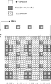
- FIG. 16 is a diagram illustrating an arrangement example of resource element groups in a downlink radio frame of the communication system 1 according to the embodiment of the present invention.
- the resource element group used for the first PDCCH is shown, and illustrations and descriptions of unrelated parts (PDSCH, second PDCCH, UE-specific RS, CSI-RS) are omitted.
- one resource element group is configured by four downlink resource elements adjacent in the frequency domain.
- FIG. 16 it shows that the downlink resource element to which the same code
- resource element R0 (downlink reference signal for antenna port 0) and R1 (downlink reference signal for antenna port 1) in which downlink reference signals are arranged are skipped to form a resource element group.
- numbering symbol “1” is performed from the resource element group of the first OFDM symbol having the lowest frequency, and then the resource element group of the second OFDM symbol having the lowest frequency is numbered.
- CCE is composed of a plurality of resource element groups shown in FIG.
- one CCE is composed of nine different resource element groups distributed in the frequency domain and the time domain.
- one second PDCCH region is composed of a plurality of DL PRB pairs, it may be composed of DL PRB pairs dispersed in the frequency domain, or may be composed of DL PRB pairs that are continuous in the frequency domain.
- the base station device 3 can configure the second PDCCH region for each of the plurality of mobile station devices 5.
- an E-CCE aggregation number having a large number of E-CCEs constituting the second PDCCH is used. Also, for example, when the base station device 3 transmits DCI with a small number of bits, when using an E-CCE aggregation number with a small number of E-CCEs constituting the second PDCCH and transmits DCI with a large number of bits. The E-CCE aggregation number having a large number of E-CCEs constituting the second PDCCH is used.
- FIG. 20 is a diagram showing an example of the configuration of the E-CCE according to the embodiment of the present invention. Compared with the example shown in FIG. 19, the number of antenna ports of UE-specific RS is different, and three or four transmission antennas (antenna port 7, antenna port 8, antenna port 9, antenna port 10, not shown) A case where UE-specific RS (D1, D2) is arranged is shown.
- E-CCEs that make up one Distributed E-PDCCH use E-CCEs with different E-CCE numbers (different frequency positions) in each DL PRB pair.
- the Distributed E-PDCCH may be configured. For example, E-CCE with the smallest E-CCE number within a certain DL PRB pair (lowest in the frequency domain) and E-CCE number within a certain DL PRB pair are second smallest (second in frequency) (Low) E-CCE, E-CCE number is the third smallest (third lowest in frequency) in a DL PRB pair, and E-CCE number is fourth in a certain DL PRB pair
- a single distributed E-PDCCH may be configured from an E-CCE having the smallest (fourth lowest in frequency) (the highest E-CCE number) (the highest in the frequency domain).
- E-CCE aggregation number candidates (candidate combinations) for the localized E-PDCCH, the number of UE-specific RS antennas, and each E-CCE May be associated in advance with the relationship of the antenna to which.
- the base station apparatus 3 indicates only information on candidates for the E-CCE aggregation number for the localized E-PDCCH to the mobile station apparatus 5 using RRC signaling, and the mobile station apparatus 5 displays the E-CCE aggregation for the E-PDCCH.
- the number of UE-specific RS antennas and the relationship between the antennas corresponding to each E-CCE are recognized from information on the number candidates.
- the base station apparatus 3 shows only information indicating the number of UE-specific RS antennas in the second PDCCH region to which the first physical resource mapping is applied to the mobile station apparatus 5 using RRC signaling,
- the device 5 recognizes the relationship between the E-CCE aggregation number candidate for the localized E-PDCCH and the antenna corresponding to each E-CCE from the information indicating the number of UE-specific RS antennas.
- UE-specific RSs of four transmission antennas are arranged.
- the UE-specific RS of one transmission antenna is arranged.
- two transmit antennas are used when transmission diversity such as SFBC (Space Frequency Block Coding) is applied to the distributed E-PDCCH. 7.
- the UE-specific RS of the antenna port 8) may be arranged.
- different second PDCCH candidates are composed of different E-CCEs (including one E-CCE and a plurality of E-CCEs).
- the E-CCEs constituting the plurality of second PDCCH candidates of the search space set in the second PDCCH region to which the first physical resource mapping is applied are a plurality of E-CCEs having consecutive E-CCE numbers. is there.
- the E-CCEs constituting the plurality of second PDCCH candidates of the search space set in the second PDCCH region to which the second physical resource mapping is applied are a plurality of non-consecutive E-CCEs having E-CCE numbers. It is.
- the first E-CCE number used for the search space in the second PDCCH region is set for each mobile station apparatus 5.
- the first E-CCE number used for the search space is set by a random function using an identifier (mobile station identifier) assigned to the mobile station device 5.
- the base station apparatus 3 notifies the mobile station apparatus 5 of the first E-CCE number used for the search space using RRC signaling.
- the number of second PDCCH candidates for the first Search space may be different from the number of second PDCCH candidates for the second Search space.
- the second PDCCH to which precoding processing is applied is basically used, and when it is difficult for the base station apparatus 3 to realize precoding processing more suitable for some situation, the precoding processing is not applied, and the frequency
- the number of second PDCCH candidates in the first search space is set larger than the number of second PDCCH candidates in the second search space. May be.
- the number of second PDCCH candidates for the search space in one second PDCCH region can be varied. For example, as the number of second PDCCH regions configured in the mobile station device 5 increases, the number of second PDCCH candidates for the search space in one second PDCCH region is decreased.
- the reception processing unit 101 detects (receives) a preamble sequence from the received PRACH signal received from the mobile station apparatus 5 by the reception antenna 109 in accordance with the instruction of the control unit 105.
- the reception processing unit 101 also estimates arrival timing (reception timing) along with detection of the preamble sequence.
- the reception processing unit 101 performs processing of detecting a preamble sequence for an uplink subframe, UL PRB pair, to which the device itself has assigned PRACH resources.
- the reception processing unit 101 outputs information regarding the estimated arrival timing to the control unit 105.
- the data modulation unit 221 uses the data encoded by the turbo coding unit 219 as a modulation method input from the control unit 105, for example, QPSK (quadrature phase shift keying; Quadrature Phase Shift Keying), 16QAM (16-value quadrature amplitude modulation). Modulation is performed using a modulation scheme such as 16 Quadrature Amplitude Modulation) or 64QAM (64-value quadrature amplitude modulation; 64 Quadrature Amplitude Modulation) to generate a signal sequence of modulation symbols.
- the data modulation unit 221 outputs the generated signal sequence to the precoding processing unit 229.
- a UE-specific RS for which precoding processing is not performed in the precoding processing unit 231 is UE-specific RS in the DL PRB pair used for the second PDCCH in the second PDCCH region of the second physical resource mapping. It is.
- the precoding processing unit 231 performs precoding processing on a part of the UE-specific RS input from the downlink pilot channel processing unit 205 and outputs the result to the multiplexing unit 207.
- the UE-specific RS for which precoding processing is performed by the precoding processing unit 231 is a UE-specific RS in the DL PRB pair used for the second PDCCH in the second PDCCH region of the first physical resource mapping. is there.
- Multiplexer 207 receives a signal input from downlink pilot channel processor 205, a signal input from each physical downlink shared channel processor 201, and a signal input from each physical downlink control channel processor 203. Are multiplexed into the downlink subframe according to the instruction from the control unit 105. Control signals related to DL PRB pair allocation to the PDSCH set by the radio resource control unit 103, resource allocation to the PDCCH (first PDCCH, second PDCCH), and physical resource mapping in the second PDCCH region The control unit 105 controls the processing of the multiplexing unit 207 based on the control signal.
- the subcarrier demapping unit 315 separates the signal demodulated by the FFT unit 313 into DM RS, SRS, PUSCH signal, and PUCCH signal based on the control signal input from the control unit 105.
- the subcarrier demapping unit 315 outputs the separated DM RS to the propagation path estimation unit 317, outputs the separated SRS to the SRS processing unit 333, and outputs the separated PUSCH signal to the PUSCH propagation path equalization unit 319.
- the separated PUCCH signal is output to the PUCCH channel equalization unit 321.
- the propagation path estimation unit 317 estimates propagation path fluctuations using the DM RS separated by the subcarrier demapping unit 315 and a known signal.
- the propagation path estimation unit 317 outputs the estimated propagation path estimation value to the PUSCH propagation path equalization unit 319 and the PUCCH propagation path equalization unit 321.
- the PUSCH channel equalization unit 319 equalizes the amplitude and phase of the PUSCH signal separated by the subcarrier demapping unit 315 based on the channel estimation value input from the channel estimation unit 317.
- equalization refers to a process for restoring the fluctuation of the propagation path received by the signal during wireless communication.
- PUSCH propagation path equalization section 319 outputs the adjusted signal to IDFT section 323.
- the reception processing unit 401 measures downlink reception quality (RSRP: “Reference” Signal “Received Power”) and outputs the measurement result to the control unit 405.
- the reception processing unit 401 measures (calculates) RSRP from CRS or CSI-RS based on an instruction from the control unit 405. Details of the reception processing unit 401 will be described later.
- the PDCCH channel compensation unit 519 adjusts the amplitude and phase of the PDCCH signal separated by the demultiplexing unit 511 according to the channel compensation value input from the channel estimation unit 513.
- the channel compensation unit 519 for PDCCH adjusts the second PDCCH signal according to the channel compensation value generated based on the UE-specific RS by the channel estimation unit 513, and performs the first PDCCH signal transmission.
- the signal is adjusted according to the channel compensation value generated based on the CRS by the channel estimation unit 513 with respect to the signal.
- the PDCCH propagation path compensation unit 519 designates each E-CCE signal in the DL PRB pair in the second PDCCH region from the control unit 405, and transmits a corresponding transmission antenna (antenna port) to each E-CCE. ) According to the propagation path compensation value generated based on UE-specific RS. PDCCH propagation path compensation section 519 outputs the adjusted signal to PDCCH demapping section 533.
- the physical downlink control channel decoding unit 521 demodulates and decodes the signal input from the PDCCH channel compensation unit 519 as described below, and detects control data.
- the QPSK demodulator 527 performs QPSK demodulation on the PDCCH signal and outputs the result to the Viterbi decoder 529.
- the Viterbi decoder unit 529 decodes the signal demodulated by the QPSK demodulator 527 and outputs the decoded DCI to the controller 405.
- this signal is expressed in bit units, and the Viterbi decoder unit 529 also performs rate dematching in order to adjust the number of bits for which Viterbi decoding processing is performed on the input bits.
- the number of candidates for the second PDCCH may be different.
- the number of second PDCCH candidates in the search space (search space for the second PDCCH) of the second PDCCH region to which the first physical resource mapping is applied is the second number to which the second physical resource mapping is applied.
- the number may be larger than the number of second PDCCH candidates in the search space of the PDCCH region (search space for the second PDCCH).
- the number of second PDCCH candidates in the search space of the second PDCCH region to which the first physical resource mapping is applied (the search space for the second PDCCH)
- the second The number of second PDCCH candidates in the search space (search space for the second PDCCH) of the second PDCCH region to which the physical resource mapping is applied is the same.
- the number of second PDCCH candidates in the search space (search space for the second PDCCH) of the second PDCCH region to which physical resource mapping is applied, and the second PDCCH region to which the second physical resource mapping is applied Search space (second PDCCH The number of second PDCCH candidates of Search space) of may be different.
- the random access channel processing unit 629 generates a signal to be transmitted by PRACH using the preamble sequence instructed by the control unit 405, and outputs the generated signal to the transmission power adjustment unit 627.
- the transmission power adjustment unit 627 adjusts the transmission power based on the control signal from the control unit 405 with respect to the signal input from the GI insertion unit 625 or the signal input from the random access channel processing unit 629, and performs D / Output to A section 605.
- the transmission power adjustment unit 627 controls the average transmission power of PUSCH, PUCCH, DM RS, SRS, and PRACH for each uplink subframe.
- FIG. 7 shows the setting of the search space in the second PDCCH region of the mobile station apparatus 5 according to the embodiment of the present invention, the setting of the number of UE-specific RS transmission antennas in the DL PRB pair, and the DL PRB pair.
- It is a flowchart which shows an example of the process in connection with the setting of UE-specific RS used for the demodulation of each E-CCE.
- an example of processing in the second PDCCH region to which the first physical resource mapping is applied will be described.
- a case where there are two types of candidate sets of E-CCE aggregation number (first candidate set and second candidate set) is shown.
- first number and second number a case where there are two types of UE-specific RS transmission antennas in the DL PRB pair (first number and second number) is shown.
- the first number is two.
- the second number is four.
- the third number and the fourth number may be further configured.
- the third number is 1.
- the fourth number is three.
- the mobile station apparatus 5 divides each E-CCE signal in the DL PRB pair into a plurality of groups, and assigns each E-CCE signal in the same group to a UE-specific corresponding to a common transmission antenna.
- Demodulation is performed using RS, and signals of different groups of E-CCEs (E-CCEs) are set to be demodulated using UE-specific RSs corresponding to different transmission antennas (step S107).
- the signal modulated from the downlink control data is arranged as compared to the case where the UE-specific RS transmission antenna is the first number. -The number of downlink resource elements in the CCE is large.
- FIG. 8 shows the setting of the search space in the second PDCCH region of the base station apparatus 3 according to the embodiment of the present invention, the setting of the number of UE-specific RS transmission antennas in the DL PRB pair, and the DL PRB pair.
- an example of processing in the second PDCCH region to which the first physical resource mapping is applied will be described.
- a case where there are two types of candidate sets of E-CCE aggregation number is shown.
- a signal modulated from downlink control data may be arranged as compared to the case of the first number of UE-specific RS transmission antennas.
- the base station apparatus 3 determines which (including all) E-CCE signal to transmit the second PDCCH for each downlink subframe. Schedule.
- the base station apparatus 3 has the first number (for example, 4) of antenna ports (UE-specific RS antenna ports) Control to transmit signals of each first element (E-CCE) in the physical resource block pair (PRB pair) using different antenna ports (antenna ports used for transmitting UE-specific RS) If the number of antenna ports (UE-specific RS antenna ports) is the second number (for example, two), a plurality of first elements (E-CCE) in the physical resource block pair (PRB pair) Of a plurality of groups (for example, two groups.
- Each group includes two E-CCEs) ) And transmit signals of each first element (E-CCE) in the same group using a common antenna port (antenna port also used for transmitting UE-specific RS), and different groups
- the first element (E-CCE) is controlled to be transmitted using different antenna ports (antenna ports used for transmitting UE-specific RS).
- the mobile station device 5 is configured such that when the number of antenna ports (UE-specific RS antenna ports) is the first number (for example, four), The reference signal (UE-specific RS) corresponding to each different antenna port (UE-specific RS antenna port) is used for each first element (E-CCE) signal in the physical resource block pair (PRB pair).
- the base station apparatus 3 substantially performs precoding processing on a signal for each minimum unit (one E-CCE or a plurality of E-CCEs) of E-CCE used for the mobile station apparatus 5.
- the mobile station apparatus 5 can receive the second PDCCH signal that has been subjected to the precoding process in the base station apparatus 3, and the second PDCCH characteristic received by the mobile station apparatus 5 can be received. Improvements can be made.
- the program when distributing to the market, can be stored and distributed on a portable recording medium, or transferred to a server computer connected via a network such as the Internet.
- the storage device of the server computer is also included in the present invention.
- LSI which is typically an integrated circuit.
- Each functional block of the mobile station device 5 and the base station device 3 may be individually chipped, or a part or all of them may be integrated into a chip.
- the method of circuit integration is not limited to LSI, and may be realized by a dedicated circuit or a general-purpose processor.
- an integrated circuit based on the technology can also be used.
- Each functional block of the mobile station device 5 and the base station device 3 may be realized by a plurality of circuits.
- a plurality of physical resource block pairs are configured as a control channel region, which is a region where a control channel may be arranged, and a first resource block is divided from the resources obtained by dividing one physical resource block pair.
- Base station apparatus 4 (A to C) RRH 5 (A to C) mobile station apparatus 101 reception processing unit 103 radio resource control unit 105 control unit 107 transmission processing unit 109 reception antenna 111 transmission antenna 201 physical downlink shared channel processing unit 203 physical downlink control channel processing unit 205 downlink Pilot channel processing section 207 Multiplexing section 209 IFFT section 211 GI insertion section 213 D / A section 215 Transmission RF section 219 Turbo coding section 221 Data modulation section 223 Convolution coding section 225 QPSK modulation section 227 Precoding processing section (for PDCCH) 229 Precoding processing unit (for PDSCH) 231 Precoding processing unit (for downlink pilot channel) 301 reception RF unit 303 A / D unit 309 symbol timing detection unit 311 GI removal unit 313 FFT unit 315 subcarrier demapping unit 317 propagation channel estimation unit 319 propagation channel equalization unit (for PUSCH) 321 Channel equalization unit (for PUCCH) 323 IDFT unit 325 Data demodulation unit
Abstract
The present invention makes it possible to efficiently transmit and receive signals, such as control information, between a base station device and a mobile station device. An enhanced physical downlink control channel (EPDCCH) is configured from a set of one or more resources in which one physical resource block (PRB) pair is divided. In cases when the total number of antenna ports for transmitting reference signals used in the demodulation of signals arranged in the EPDCCH is 4, each resource in which the one PRB pair is divided into 4 corresponds to a different number antenna port, and decoding detection is performed. In cases when the total number of antenna ports for transmitting reference signals used in the demodulation of signals arranged in the EPDCCH is 2, each resource in which the one PRB pair is divided into 2 corresponds to a different number antenna port, and decoding detection is performed. The present invention has a reception processing unit which performs the decoding detection, and which demodulates the signals arranged in the EPDCCH using the reference signals transmitted from the antenna ports corresponding to the resources used as the EPDCCH.
Description
本発明は、複数の移動局装置と基地局装置から構成される通信システムにおいて、制御情報を含む信号が配置される可能性のある領域を効率的に設定し、基地局装置が移動局装置に対して効率的に制御情報を含む信号を送信することができ、移動局装置は基地局装置から効率的に制御情報を含む信号を受信することができる通信システム、移動局装置、基地局装置、通信方法および集積回路に関する。
The present invention efficiently sets an area in which a signal including control information may be arranged in a communication system including a plurality of mobile station apparatuses and a base station apparatus. A communication system, a mobile station apparatus, a base station apparatus, a mobile station apparatus that can efficiently transmit a signal including control information and a mobile station apparatus that can efficiently receive a signal including control information from the base station apparatus, The present invention relates to a communication method and an integrated circuit.
セルラー移動通信の無線アクセス方式および無線ネットワークの進化(以下、「Long Term Evolution (LTE)」、または、「Evolved Universal Terrestrial Radio Access (EUTRA)」と呼称する。)が、第三世代パートナーシッププロジェクト(3rd Generation Partnership Project: 3GPP)において仕様化されている。LTEでは、基地局装置から移動局装置への無線通信(下りリンク; DLと呼称する。)の通信方式として、マルチキャリア送信である直交周波数分割多重(Orthogonal Frequency Division Multiplexing: OFDM)方式が用いられる。また、LTEでは、移動局装置から基地局装置への無線通信(上りリンク; ULと呼称する。)の通信方式として、シングルキャリア送信であるSC-FDMA(Single-Carrier Frequency Division Multiple Access)方式が用いられる。LTEでは、SC-FDMA方式としてDFT-Spread OFDM(Discrete Fourier Transform-Spread OFDM)方式が用いられる。
The wireless access method and wireless network evolution of cellular mobile communications (hereinafter referred to as “Long Term Evolution (LTE)” or “Evolved Universal Terrestrial Radio Access (EUTRA)”) is the third generation partnership project (3rd Generation (Partnership Project: 3GPP)). In LTE, an orthogonal frequency division multiplexing (OFDM) method, which is multicarrier transmission, is used as a communication method (downlink; referred to as “DL”) from a base station device to a mobile station device. . In LTE, a SC-FDMA (Single-Carrier-Frequency-Division-Multiple-Access) system, which is single carrier transmission, is used as a communication system (uplink; referred to as UL) from a mobile station apparatus to a base station apparatus. Used. In LTE, the DFT-Spread OFDM (Discrete-Fourier-Transform-Spread-OFDM) system is used as the SC-FDMA system.
LTE-A(LTE-Advanced)ではLTEと同一のチャネル構造を少なくともサポートすることが検討されている。チャネルとは、信号の送信に用いられる媒体を意味する。物理層で用いられるチャネルは物理チャネル、媒体アクセス制御(Medium Access Control: MAC)層で用いられるチャネルは論理チャネルと呼称する。物理チャネルの種類としては、下りリンクのデータおよび制御情報の送受信に用いられる物理下りリンク共用チャネル(Physical Downlink Shared CHannel: PDSCH)、下りリンクの制御情報の送受信に用いられる物理下りリンク制御チャネル(Physical Downlink Control CHannel: PDCCH)、上りリンクのデータおよび制御情報の送受信に用いられる物理上りリンク共用チャネル(Physical Uplink Shared CHannel: PUSCH)、制御情報の送受信に用いられる物理上りリンク制御チャネル(Physical Uplink Control CHannel: PUCCH)、下りリンクの同期確立のために用いられる同期チャネル(Synchronization CHannel: SCH)、上りリンクの同期確立のために用いられる物理ランダムアクセスチャネル(Physical Random Access CHannel: PRACH)、下りリンクのシステム情報の送信に用いられる物理報知チャネル(Physical Broadcast CHannel: PBCH)等がある。移動局装置、または基地局装置は、制御情報、データなどから生成した信号を各物理チャネルに配置して、送信する。物理下りリンク共用チャネル、または物理上りリンク共用チャネルで送信されるデータは、トランスポートブロックと呼称する。
LTE-A (LTE-Advanced) has been studied to support at least the same channel structure as LTE. A channel means a medium used for signal transmission. A channel used in the physical layer is called a physical channel, and a channel used in a medium access control (Medium Access Control: MAC) layer is called a logical channel. Physical channel types include physical downlink shared channel (Physical Downlink Shared CHannel: PDSCH) used for transmission / reception of downlink data and control information, and physical downlink control channel (Physical) used for transmission / reception of downlink control information. Downlink Control CHannel: PDCCH), physical uplink shared channel (Physical Uplink Shared CHannel: PUSCH) used for transmission and reception of uplink data and control information, physical uplink control channel (Physical Uplink Control CHannel used for transmission and reception of control information : PUCCH), synchronization channel used to establish downlink synchronization (Synchronization CHannel: SCH), physical random access channel used to establish uplink synchronization (Physical Random Access CHannel: PRACH), downlink system Physical broadcast used for information transmission There are channels (Physical Broadcast CHannel: PBCH). A mobile station apparatus or a base station apparatus arranges and transmits a signal generated from control information, data, and the like on each physical channel. Data transmitted on the physical downlink shared channel or the physical uplink shared channel is referred to as a transport block.
物理上りリンク制御チャネルに配置される制御情報は、上りリンク制御情報(Uplink Control Information: UCI)と呼称する。上りリンク制御情報は、受信された物理下りリンク共用チャネルに配置されたデータに対する肯定応答(Acknowledgement: ACK)または否定応答(Negative Acknowledgement: NACK)を示す制御情報(受信確認応答; ACK/NACK)、または上りリンクのリソースの割り当ての要求を示す制御情報(Scheduling Request: SR)、または下りリンクの受信品質(チャネル品質とも呼称する)を示す制御情報(Channel Quality Indicator: CQI)である。
The control information arranged in the physical uplink control channel is referred to as uplink control information (Uplink Control Information: UCI). Uplink control information is control information (reception acknowledgment; ACK / NACK) indicating an acknowledgment (Acknowledgement: ACK) or a negative response (Negative Acknowledgement: NACK) for the data arranged in the received physical downlink shared channel, Alternatively, it is control information (Scheduling Request: SR) indicating a request for uplink resource allocation, or control information (Channel Quality Indicator: CQI) indicating downlink reception quality (also referred to as channel quality).
<協調通信>
LTE-Aでは、セル端領域の移動局装置に対する干渉を軽減または抑圧するために、または受信信号電力を増大させるために、隣接セル間で互いに協調して通信を行なうセル間協調通信(Cooperative Multipoint: CoMP通信)が検討されている。なお、例えば、基地局装置が任意の1つの周波数帯域を用いて通信する形態のことを「セル(Cell)」と呼称する。例えば、セル間協調通信として、複数のセルで異なる重み付け信号処理(プリコーディング処理)が信号に適用され、複数の基地局装置がその信号を協調して同一の移動局装置に送信する方法(Joint Processing、Joint Transmissionとも称す)などが検討されている。この方法では、移動局装置の信号電力対干渉雑音電力比を向上することができ、移動局装置における受信特性を改善することができる。例えば、セル間協調通信として、複数のセルで協調して移動局装置に対してスケジューリングを行う方法(Coordinated Scheduling: CS)が検討されている。この方法では、移動局装置の信号電力対干渉雑音電力比を向上することができる。例えば、セル間協調通信として、複数のセルで協調してビームフォーミングを適用して移動局装置に信号を送信する方法(Coordinated beamforming:CB)が検討されている。この方法では、移動局装置の信号電力対干渉雑音電力比を向上することができる。例えば、セル間協調通信として、一方のセルでのみ所定のリソースを用いて信号を送信し、一方のセルでは所定のリソースで信号を送信しない方法(Blanking, Muting)が検討されている。この方法では、移動局装置の信号電力対干渉雑音電力比を向上することができる。 <Collaborative communication>
In LTE-A, in order to reduce or suppress interference with a mobile station apparatus in a cell edge region, or to increase received signal power, inter-cell cooperative communication (Cooperative Multipoint) in which communication is performed in cooperation between adjacent cells. : CoMP communication). For example, a mode in which the base station apparatus communicates using any one frequency band is referred to as a “cell”. For example, as inter-cell cooperative communication, different weighting signal processing (precoding processing) is applied to a signal in a plurality of cells, and a plurality of base station devices cooperates to transmit the signal to the same mobile station device (Joint Processing, also called Joint Transmission). In this method, the signal power to interference noise power ratio of the mobile station apparatus can be improved, and reception characteristics in the mobile station apparatus can be improved. For example, as a cooperative communication between cells, a method (Coordinated Scheduling: CS) in which scheduling is performed for a mobile station device in cooperation with a plurality of cells has been studied. In this method, the signal power to interference noise power ratio of the mobile station apparatus can be improved. For example, as a coordinated inter-cell communication, a method (Coordinated beamforming: CB) in which a signal is transmitted to a mobile station apparatus by applying beamforming in cooperation with a plurality of cells has been studied. In this method, the signal power to interference noise power ratio of the mobile station apparatus can be improved. For example, as inter-cell cooperative communication, a method (Blanking, Muting) in which a signal is transmitted using a predetermined resource only in one cell and a signal is not transmitted using a predetermined resource in one cell has been studied. In this method, the signal power to interference noise power ratio of the mobile station apparatus can be improved.
なお、協調通信に用いられる複数のセルに関して、異なるセルは異なる基地局装置により構成されてもよいし、異なるセルは同じ基地局装置に管理される異なるRRH(Remote Radio Head、基地局装置より小型の屋外型の無線部、Remote Radio Unit: RRUとも称す)により構成されてもよいし、異なるセルは基地局装置とその基地局装置に管理されるRRHにより構成されてもよいし、異なるセルは基地局装置とその基地局装置とは異なる基地局装置に管理されるRRHにより構成されてもよい。
In addition, regarding a plurality of cells used for cooperative communication, different cells may be configured by different base station apparatuses, and different cells are smaller than different RRHs (Remote Radio Head, base station apparatus managed by the same base station apparatus) Outdoor type radio unit, Remote Radio Unit: also referred to as RRU), different cells may be constituted by base station apparatus and RRH managed by the base station apparatus, and different cells may be The base station apparatus and the base station apparatus may be configured by RRH managed by a different base station apparatus.
カバレッジの広い基地局装置は、一般的にマクロ基地局装置と呼称する。カバレッジの狭い基地局装置は、一般的にピコ基地局装置、またはフェムト基地局装置と呼称する。RRHは、一般的に、マクロ基地局装置よりもカバレッジが狭いエリアでの運用が検討されている。マクロ基地局装置と、RRHにより構成され、マクロ基地局装置によりサポートされるカバレッジがRRHによりサポートされるカバレッジの一部または全部を含んで構成される通信システムのような展開は、ヘテロジーニアスネットワーク展開と呼称する。そのようなヘテロジーニアスネットワーク展開の通信システムにおいて、マクロ基地局装置とRRHが、お互いに重複したカバレッジ内に位置する移動局装置に対して、協調して信号を送信する方法が検討されている。ここで、RRHは、マクロ基地局装置により管理され、送受信が制御されている。なお、マクロ基地局装置とRRHは、光ファイバ等の有線回線や、リレー技術を用いた無線回線により接続されている。このように、マクロ基地局装置とRRHがそれぞれ一部または全部が同一の無線リソースを用いて協調通信を実行することで、マクロ基地局装置が構築するカバレッジのエリア内の総合的な周波数利用効率(伝送容量)が向上できる。
A base station apparatus with a wide coverage is generally called a macro base station apparatus. A base station apparatus with a narrow coverage is generally called a pico base station apparatus or a femto base station apparatus. RRH is generally considered to be used in an area where the coverage is narrower than that of a macro base station apparatus. A deployment such as a communication system configured by a macro base station apparatus and an RRH, and a coverage supported by the macro base station apparatus including a part or all of the coverage supported by the RRH is a heterogeneous network deployment. Called. In such a heterogeneous network-deployed communication system, a method in which a macro base station apparatus and an RRH transmit signals in a coordinated manner to mobile station apparatuses located within the overlapping coverage of each other has been studied. Here, RRH is managed by the macro base station apparatus, and transmission / reception is controlled. Note that the macro base station apparatus and the RRH are connected by a wired line such as an optical fiber or a wireless line using a relay technology. As described above, the macro base station apparatus and the RRH perform cooperative communication using radio resources that are partly or entirely the same, so that the overall frequency use efficiency in the coverage area constructed by the macro base station apparatus is increased. (Transmission capacity) can be improved.
移動局装置は、マクロ基地局装置またはRRHの付近に位置している場合、マクロ基地局装置またはRRHとシングルセル通信することができる。つまり、ある移動局装置は、協調通信を用いずに、マクロ基地局装置またはRRHと通信を行い、信号の送受信を行なう。例えば、マクロ基地局装置は、自装置に距離的に近い移動局装置からの上りリンクの信号を受信する。例えば、RRHは、自装置に距離的に近い移動局装置からの上りリンクの信号を受信する。さらに、移動局装置は、RRHが構築するカバレッジの端付近(セルエッジ)に位置する場合、マクロ基地局装置からの同一チャネル干渉に対する対策が必要になる。マクロ基地局装置とRRHとのマルチセル通信(協調通信)として、隣接基地局装置間で互いに協調するCoMP方式を用いることにより、セルエッジ領域の移動局装置に対する干渉を軽減または抑圧する方法が検討されている。
When the mobile station apparatus is located in the vicinity of the macro base station apparatus or RRH, the mobile station apparatus can perform single cell communication with the macro base station apparatus or RRH. That is, a certain mobile station apparatus communicates with a macro base station apparatus or RRH without using cooperative communication, and transmits and receives signals. For example, the macro base station apparatus receives an uplink signal from a mobile station apparatus that is close in distance to itself. For example, the RRH receives an uplink signal from a mobile station apparatus that is close in distance to the own apparatus. Furthermore, when the mobile station apparatus is located near the edge of the coverage constructed by the RRH (cell edge), it is necessary to take measures against co-channel interference from the macro base station apparatus. As a multi-cell communication (cooperative communication) between a macro base station apparatus and an RRH, a method of reducing or suppressing interference with a mobile station apparatus in a cell edge region by using a CoMP scheme in which adjacent base station apparatuses cooperate with each other has been studied. Yes.
また、移動局装置は、下りリンクでは、協調通信を用いて、マクロ基地局装置とRRHの双方から送信された信号を受信し、上りリンクでは、マクロ基地局装置、またはRRHの何れかに対して適した形で信号を送信することが検討されている。例えば、移動局装置は、マクロ基地局装置で信号が受信されるのに適した送信電力で上りリンクの信号を送信する。例えば、移動局装置は、RRHで信号が受信されるのに適した送信電力で上りリンクの信号を送信する。これにより、上りリンクの不必要な干渉を低減し、周波数利用効率を向上できる。
In the downlink, the mobile station apparatus receives signals transmitted from both the macro base station apparatus and the RRH using cooperative communication. In the uplink, the mobile station apparatus receives either the macro base station apparatus or the RRH. Therefore, it is considered to transmit a signal in a suitable form. For example, the mobile station apparatus transmits an uplink signal with transmission power suitable for reception of a signal by the macro base station apparatus. For example, the mobile station apparatus transmits an uplink signal with transmission power suitable for receiving a signal by RRH. Thereby, unnecessary interference in the uplink can be reduced and the frequency utilization efficiency can be improved.
移動局装置において、データ信号の受信処理に関して、データ信号に用いられる変調方式、符号化率、空間多重数、送信電力調整値、リソースの割り当てなどを示す制御情報を取得する必要がある。LTE-Aでは、データ信号に関する制御情報を送信する新しい制御チャネルを導入することが検討されている(非特許文献1)。例えば、全体の制御チャネルのキャパシティを改善することが検討されている。例えば、新しい制御チャネルに対して周波数領域での干渉コーディネーションをサポートすることが検討されている。例えば、新しい制御チャネルに対して空間多重をサポートすることが検討されている。例えば、新しい制御チャネルに対してビームフォーミングをサポートすることが検討されている。例えば、新しい制御チャネルに対してダイバーシチをサポートすることが検討されている。例えば、新しい制御チャネルを新しいタイプのキャリアで用いることが検討されている。例えば、新しいタイプのキャリアでは、セル内の全ての移動局装置に対して共通である参照信号の送信を行わないことが検討されている。例えば、新しいタイプのキャリアでは、セル内の全ての移動局装置に対して共通である参照信号の送信頻度を従来よりも減らすことが検討されている。例えば、新しいタイプのキャリアでは、移動局装置において固有の参照信号を用いて制御情報等の信号を復調することが検討されている。
In the mobile station apparatus, regarding the data signal reception process, it is necessary to acquire control information indicating the modulation scheme, coding rate, spatial multiplexing number, transmission power adjustment value, resource allocation, etc. used for the data signal. In LTE-A, introduction of a new control channel for transmitting control information related to a data signal has been studied (Non-Patent Document 1). For example, improving the overall control channel capacity is being considered. For example, it has been considered to support interference coordination in the frequency domain for a new control channel. For example, it is considered to support spatial multiplexing for a new control channel. For example, it is considered to support beamforming for a new control channel. For example, it is considered to support diversity for a new control channel. For example, the use of new control channels with new types of carriers is being considered. For example, in a new type of carrier, it is considered that a reference signal that is common to all mobile station apparatuses in a cell is not transmitted. For example, in a new type of carrier, it is considered to reduce the transmission frequency of a reference signal that is common to all mobile station apparatuses in a cell as compared with the conventional case. For example, in a new type of carrier, it is considered to demodulate a signal such as control information using a unique reference signal in a mobile station apparatus.
例えば、ビームフォーミングの適用として、新しい制御チャネルに対して協調通信、複数アンテナ送信を適用することが検討されている。具体的には、LTE-Aに対応した複数の基地局装置、複数のRRHが、新しい制御チャネルの信号に対してプリコーディング処理を適用し、その新しい制御チャネルの信号を復調するための参照信号(Reference Signal: RS)に対しても同じプリコーディング処理を適用することが検討されている。具体的には、LTE-Aに対応した複数の基地局装置、複数のRRHが、同じプリコーディング処理が適用される新しい制御チャネルの信号とRSを、LTEにおいてはPDSCHが配置されるリソースの領域に配置し、送信することが検討されている。LTE-Aに対応した移動局装置は、受信したRSであって、プリコーディング処理が行われたRSを用いて、同じプリコーディング処理が行われた新しい制御チャネルの信号を復調し、制御情報を取得することが検討されている。この方法では、基地局装置と移動局装置間で新しい制御チャネルの信号に適用したプリコーディング処理に関する情報をやり取りする必要がなくなる。
For example, application of cooperative communication and multi-antenna transmission to a new control channel is being studied as an application of beamforming. Specifically, a reference signal for a plurality of base station apparatuses and a plurality of RRHs corresponding to LTE-A to apply a precoding process to a new control channel signal and demodulate the new control channel signal The application of the same precoding processing to Reference (Signal: RS) is also under consideration. Specifically, a plurality of base station apparatuses corresponding to LTE-A, a plurality of RRHs, and a new control channel signal and RS to which the same precoding process is applied, a resource region in which PDSCH is arranged in LTE It is being considered to place and send. The mobile station apparatus supporting LTE-A demodulates the signal of the new control channel that has been subjected to the same precoding process using the received RS that has been subjected to the precoding process, and obtains control information. It is being considered to acquire. This method eliminates the need for exchanging information about precoding processing applied to a new control channel signal between the base station apparatus and the mobile station apparatus.
例えば、ダイバーシチの適用として、周波数領域で離れたリソースを用いて新しい制御チャネルの信号を構成して、周波数ダイバーシチの効果を得る方法が検討されている。一方、ビームフォーミングが新しい制御チャネルに適用される場合は、周波数領域で離れていないリソースを用いて新しい制御チャネルの信号を構成する方法が検討されている。
For example, as an application of diversity, a method of obtaining a frequency diversity effect by constructing a new control channel signal using resources separated in the frequency domain is being studied. On the other hand, when beamforming is applied to a new control channel, a method of configuring a new control channel signal using resources that are not separated in the frequency domain has been studied.
効率的にリソースを使用して、制御チャネルが送受信されることが望ましい。移動局装置毎に対して要求条件を満たすリソースの量が制御チャネルに必要であり、効率的なリソースの使用が制御チャネルに実施されなければ、制御チャネルのキャパシティを増大することはできず、制御チャネルが割り当てられる移動局装置の数を増やすことはできない。
It is desirable to send and receive control channels using resources efficiently. The amount of resources that satisfy the requirements for each mobile station device is required for the control channel, and unless efficient use of resources is implemented for the control channel, the capacity of the control channel cannot be increased, The number of mobile station apparatuses to which control channels are assigned cannot be increased.
本発明は上記の点に鑑みてなされたものであり、その目的は、複数の移動局装置と基地局装置から構成される通信システムにおいて、制御情報を含む信号が配置される可能性のある領域を効率的に設定し、基地局装置が移動局装置に対して効率的に制御情報を含む信号を送信することができ、移動局装置は基地局装置から効率的に制御情報を含む信号を受信することができる通信システム、移動局装置、基地局装置、通信方法および集積回路に関する。
The present invention has been made in view of the above points, and an object thereof is an area in which a signal including control information may be arranged in a communication system including a plurality of mobile station apparatuses and a base station apparatus. The base station apparatus can efficiently transmit a signal including control information to the mobile station apparatus, and the mobile station apparatus efficiently receives a signal including control information from the base station apparatus. The present invention relates to a communication system, a mobile station apparatus, a base station apparatus, a communication method, and an integrated circuit.
(1)上記の目的を達成するために、本発明は、以下のような手段を講じた。すなわち、本発明の通信システムは、EPDCCH(Enhanced Physical Downlink Control CHannel)が配置される可能性のある領域として複数のPRB pair(Physical Resource Block pair)が構成され、EPDCCHは1つの前記PRB pairを分割したリソースの1個以上の集合から構成され、複数の移動局装置および前記複数の移動局装置と前記EPDCCHを用いて通信を行う基地局装置から構成される通信システムであって、1つの前記PRB pairを構成する2つのPRBのそれぞれの前記PRB内に配置される、前記EPDCCHに配置される信号の復調に用いられる参照信号を送信するアンテナポートの総数が4本の場合、1つの前記PRB pairを4つに分割したリソースのそれぞれが異なる番号のアンテナポートと対応し、1つの前記PRB pairを構成する2つのPRBのそれぞれの前記PRB内に配置される、前記EPDCCHに配置される信号の復調に用いられる参照信号を送信するアンテナポートの総数が2本の場合、1つの前記PRB pairを2つに分割したリソースのそれぞれが異なる番号のアンテナポートと対応し、前記基地局装置は、前記EPDCCHに配置される信号を前記EPDCCHに用いられる前記リソースと対応するアンテナポートを用いて送信する送信処理部を有し、前記移動局装置は、復号検出を行う、前記EPDCCHに配置される信号を前記EPDCCHに用いられる前記リソースと対応するアンテナポートから送信される参照信号を用いて復調する受信処理部を有することを特徴とする。
(1) In order to achieve the above object, the present invention has taken the following measures. That is, in the communication system of the present invention, a plurality of PRB pairs (Physical Resource Block pairs) are configured as an area where EPDCCH (Enhanced Physical Downlink Channel) may be arranged, and EPDCCH is divided into one PR. A communication system including a plurality of mobile station apparatuses and a base station apparatus that communicates with the plurality of mobile station apparatuses using the EPDCCH. When the total number of antenna ports that transmit reference signals used for demodulation of signals arranged on the EPDCCH, which are arranged in the PRBs of the two PRBs constituting the pair, is one, one The resources obtained by dividing the PRB pair into four correspond to the antenna ports of different numbers, and are arranged in the EPDCCH, which are arranged in the PRBs of two PRBs constituting one PRB pair. When the total number of antenna ports that transmit reference signals used for signal demodulation is two, each of the resources obtained by dividing one PRB pair into two corresponds to antenna ports with different numbers, and the base station apparatus And a transmission processing unit that transmits a signal arranged in the EPDCCH using an antenna port corresponding to the resource used in the EPDCCH, and the mobile station apparatus is arranged in the EPDCCH that performs decoding detection. From the antenna port corresponding to the resource used for the EPDCCH Using the reference signal to be signal and having a reception processing unit for demodulating.
(2)また、本発明の移動局装置は、EPDCCH(Enhanced Physical Downlink Control CHannel)が配置される可能性のある領域として複数のPRB pair(Physical Resource Block pair)が構成され、EPDCCHは1つの前記PRB pairを分割したリソースの1個以上の集合から構成され、基地局装置と前記EPDCCHを用いて通信を行う移動局装置であって、1つの前記PRB pairを構成する2つのPRBのそれぞれの前記PRB内に配置される、前記EPDCCHに配置される信号の復調に用いられる参照信号を送信するアンテナポートの総数が4本の場合、1つの前記PRB pairを4つに分割したリソースのそれぞれが異なる番号のアンテナポートと対応し、1つの前記PRB pairを構成する2つのPRBのそれぞれの前記PRB内に配置される、前記EPDCCHに配置される信号の復調に用いられる参照信号を送信するアンテナポートの総数が2本の場合、1つの前記PRB pairを2つに分割したリソースのそれぞれが異なる番号のアンテナポートと対応し、復号検出を行う、前記EPDCCHに配置される信号を前記EPDCCHに用いられる前記リソースと対応するアンテナポートから送信される参照信号を用いて復調する受信処理部を有することを特徴とする。
(2) Also, in the mobile station apparatus of the present invention, a plurality of PRB pairs (Physical Resource Block pairs) are configured, and one EPDCCH is configured as an area where EPDCCH (Enhanced Physical Downlink Channel) may be arranged. A mobile station apparatus that is composed of one or more sets of resources obtained by dividing a PRB pair and communicates with a base station apparatus using the EPDCCH, and each of the two PRBs that constitute one PRB pair When the total number of antenna ports that transmit reference signals used for demodulation of signals allocated to the EPDCCH arranged in the PRB is four, each of the resources obtained by dividing one PRB pair into four Antenna port corresponding to antenna ports of different numbers and transmitting a reference signal used for demodulation of a signal arranged in the EPDCCH, which is arranged in each PRB of two PRBs constituting one PRB pair When the total number of the two is two, each resource obtained by dividing one PRB pair into two corresponds to an antenna port having a different number, and a signal arranged in the EPDCCH for decoding detection is used for the EPDCCH It has a reception processing part which demodulates using a reference signal transmitted from an antenna port corresponding to the resource.
(3)また、本発明の基地局装置は、EPDCCH(Enhanced Physical Downlink Control CHannel)が配置される可能性のある領域として複数のPRB pair(Physical Resource Block pair)が構成され、EPDCCHは1つの前記PRB pairを分割したリソースの1個以上の集合から構成され、複数の移動局装置と前記EPDCCHを用いて通信を行う基地局装置であって、1つの前記PRB pairを構成する2つのPRBのそれぞれの前記PRB内に配置される、前記EPDCCHに配置される信号の復調に用いられる参照信号を送信するアンテナポートの総数が4本の場合、1つの前記PRB pairを4つに分割したリソースのそれぞれが異なる番号のアンテナポートと対応し、1つの前記PRB pairを構成する2つのPRBのそれぞれの前記PRB内に配置される、前記EPDCCHに配置される信号の復調に用いられる参照信号を送信するアンテナポートの総数が2本の場合、1つの前記PRB pairを2つに分割したリソースのそれぞれが異なる番号のアンテナポートと対応し、前記EPDCCHに配置される信号を前記EPDCCHに用いられる前記リソースと対応するアンテナポートを用いて送信する送信処理部を有することを特徴とする。
(3) Also, in the base station apparatus of the present invention, a plurality of PRB pairs (Physical Resource Block pairs) are configured as an area where EPDCCH (Enhanced Physical Downlink Channel) may be arranged, and one EPDCCH is configured as EPDCCH. Each of the two PRBs that are composed of one or more sets of resources obtained by dividing a PRB pair and communicate with a plurality of mobile station apparatuses using the EPDCCH, each of which constitutes one PRB pair In the case where the total number of antenna ports that transmit reference signals used for demodulation of signals allocated to the EPDCCH, which are allocated in the PRB, is four, one PRB pair is divided into four resources. Reference signals used for demodulation of signals arranged on the EPDCCH, which are arranged in the PRBs of two PRBs constituting one PRB pair, each corresponding to an antenna port having a different number. When the total number of antenna ports to be used is two, the resources obtained by dividing one PRB pair into two correspond to the antenna ports of different numbers, and the resources used for the EPDCCH are signals that are allocated to the EPDCCH And a transmission processing unit for transmitting using the corresponding antenna port.
(4)また、本発明の通信方法は、EPDCCH(Enhanced Physical Downlink Control CHannel)が配置される可能性のある領域として複数のPRB pair(Physical Resource Block pair)が構成され、EPDCCHは1つの前記PRB pairを分割したリソースの1個以上の集合から構成され、基地局装置と前記EPDCCHを用いて通信を行う移動局装置に用いられる通信方法であって、1つの前記PRB pairを構成する2つのPRBのそれぞれの前記PRB内に配置される、前記EPDCCHに配置される信号の復調に用いられる参照信号を送信するアンテナポートの総数が4本の場合、1つの前記PRB pairを4つに分割したリソースのそれぞれが異なる番号のアンテナポートと対応し、1つの前記PRB pairを構成する2つのPRBのそれぞれの前記PRB内に配置される、前記EPDCCHに配置される信号の復調に用いられる参照信号を送信するアンテナポートの総数が2本の場合、1つの前記PRB pairを2つに分割したリソースのそれぞれが異なる番号のアンテナポートと対応し、復号検出を行う、前記EPDCCHに配置される信号を前記EPDCCHに用いられる前記リソースと対応するアンテナポートから送信される参照信号を用いて復調するステップを含むことを特徴とする。
(4) Further, in the communication method of the present invention, a plurality of PRB pairs (Physical Resource Block pairs) are configured as an area where EPDCCH (Enhanced Physical Downlink Control Channel) may be arranged, and one EPDCCH is configured as the EPDCB. A communication method that is composed of one or more sets of resources obtained by dividing a pair and is used for a mobile station apparatus that communicates with a base station apparatus using the EPDCCH, and includes two PRBs constituting one PRB pair When the total number of antenna ports that transmit reference signals used for demodulation of signals arranged in the EPDCCH, which are arranged in each of the PRBs, is four, one PRB pair is divided into four Reference signals used for demodulation of signals arranged on the EPDCCH, each of which corresponds to an antenna port of a different number and is arranged in each of the PRBs of two PRBs constituting one PRB pair. When the total number of antenna ports to be transmitted is two, each of the resources obtained by dividing one PRB pair into two corresponds to a different number of antenna ports, and a signal arranged on the EPDCCH is subjected to decoding detection. And demodulating using a reference signal transmitted from an antenna port corresponding to the resource used for EPDCCH.
(5)また、本発明の通信方法は、EPDCCH(Enhanced Physical Downlink Control CHannel)が配置される可能性のある領域として複数のPRB pair(Physical Resource Block pair)が構成され、EPDCCHは1つの前記PRB pairを分割したリソースの1個以上の集合から構成され、複数の移動局装置と前記EPDCCHを用いて通信を行う基地局装置に用いられる通信方法であって、1つの前記PRB pairを構成する2つのPRBのそれぞれの前記PRBに配置される、前記EPDCCHに配置される信号の復調に用いられる参照信号を送信するアンテナポートの総数が4本の場合、1つの前記PRB pairを4つに分割したリソースのそれぞれが異なる番号のアンテナポートと対応し、1つの前記PRB pairを構成する2つのPRBのそれぞれの前記PRB内に配置される、前記EPDCCHに配置される信号の復調に用いられる参照信号を送信するアンテナポートの総数が2本の場合、1つの前記PRB pairを2つに分割したリソースのそれぞれが異なる番号のアンテナポートと対応し、前記EPDCCHに配置される信号を前記EPDCCHに用いられる前記リソースと対応するアンテナポートを用いて送信するステップを含むことを特徴とする。
(5) In addition, in the communication method of the present invention, a plurality of PRB pairs (Physical Resource Block pairs) are configured as an area where EPDCCH (Enhanced Physical Downlink Control Channel) may be arranged, and one EPDCCH is configured as the EPDCB. A communication method that is composed of one or more sets of resources obtained by dividing a pair and is used for a base station apparatus that communicates with a plurality of mobile station apparatuses using the EPDCCH, and constitutes one PRB pair When the total number of antenna ports that transmit reference signals used for demodulation of signals allocated to the EPDCCH, which are allocated to the PRBs of each of the PRBs, is four, one PRB pair is divided into four Reference signals used for demodulation of signals arranged on the EPDCCH, each of which corresponds to an antenna port of a different number and is arranged in the PRB of each of the two PRBs constituting one PRB pair. When the total number of antenna ports transmitting two is one, each resource obtained by dividing one PRB pair into two corresponds to a different number of antenna ports, and a signal arranged in the EPDCCH is used for the EPDCCH And transmitting using the antenna port corresponding to the resource.
(6)また、本発明の集積回路は、EPDCCH(Enhanced Physical Downlink Control CHannel)が配置される可能性のある領域として複数のPRB pair(Physical Resource Block pair)が構成され、EPDCCHは1つの前記PRB pairを分割したリソースの1個以上の集合から構成され、基地局装置と前記EPDCCHを用いて通信を行う移動局装置に実装される集積回路であって、1つの前記PRB pairを構成する2つのPRBのそれぞれの前記PRB内に配置される、前記EPDCCHに配置される信号の復調に用いられる参照信号を送信するアンテナポートの総数が4本の場合、1つの前記PRB pairを4つに分割したリソースのそれぞれが異なる番号のアンテナポートと対応し、1つの前記PRB pairを構成する2つのPRBのそれぞれの前記PRB内に配置される、前記EPDCCHに配置される信号の復調に用いられる参照信号を送信するアンテナポートの総数が2本の場合、1つの前記PRB pairを2つに分割したリソースのそれぞれが異なる番号のアンテナポートと対応し、復号検出を行う、前記EPDCCHに配置される信号を前記EPDCCHに用いられる前記リソースと対応するアンテナポートから送信される参照信号を用いて復調する受信処理部を有することを特徴とする。
(6) Further, in the integrated circuit of the present invention, a plurality of PRB pairs (Physical Resource Block pairs) are configured as a region where EPDCCH (Enhanced Physical Downlink Control Channel) may be arranged, and one EPDCCH is configured as one PRDCCH. An integrated circuit configured by one or more sets of resources obtained by dividing a pair and mounted on a mobile station apparatus that communicates with a base station apparatus using the EPDCCH, and includes two PRB pairs that constitute one PRB pair When the total number of antenna ports for transmitting the reference signals used for demodulation of signals arranged on the EPDCCH, which are arranged in the PRBs of the PRBs, is four, one PRB pair is divided into four Reference signals used for demodulation of signals arranged in the EPDCCH, each of which corresponds to an antenna port of a different number and is arranged in each of the PRBs of two PRBs constituting one PRB pair. When the total number of antenna ports to be transmitted is two, each of the resources obtained by dividing one PRB pair into two corresponds to a different number of antenna ports, and a signal arranged on the EPDCCH that performs decoding detection is It has a reception processing part which demodulates using a reference signal transmitted from an antenna port corresponding to the resource used for EPDCCH.
(7)また、本発明の集積回路、EPDCCH(Enhanced Physical Downlink Control CHannel)が配置される可能性のある領域として複数のPRB pair(Physical Resource Block pair)が構成され、EPDCCHは1つの前記PRB pairを分割したリソースの1個以上の集合から構成され、複数の移動局装置と前記EPDCCHを用いて通信を行う基地局装置に実装される集積回路であって、1つの前記PRB pairを構成する2つのPRBのそれぞれの前記PRB内に配置される、前記EPDCCHに配置される信号の復調に用いられる参照信号を送信するアンテナポートの総数が4本の場合、1つの前記PRB pairを4つに分割したリソースのそれぞれが異なる番号のアンテナポートと対応し、1つの前記PRB pairを構成する2つのPRBのそれぞれの前記PRB内に配置される、前記EPDCCHに配置される信号の復調に用いられる参照信号を送信するアンテナポートの総数が2本の場合、1つの前記PRB pairを2つに分割したリソースのそれぞれが異なる番号のアンテナポートと対応し、前記EPDCCHに配置される信号を前記EPDCCHに用いられる前記リソースと対応するアンテナポートを用いて送信する送信処理部を有することを特徴とする。
(7) In addition, a plurality of PRB pairs (Physical Resource Block pairs) are configured as an area in which the integrated circuit of the present invention, EPDCCH (Enhanced Physical Downlink Control Channel) may be arranged, and the EPDCCH1 includes the above-described EPDCB1. Is an integrated circuit that is implemented in a base station apparatus that communicates with a plurality of mobile station apparatuses using the EPDCCH, and constitutes one PRB pair. When the total number of antenna ports that transmit reference signals used for demodulation of signals arranged in the EPDCCH, which are arranged in the PRB of each of the PRBs, is four, one PRB pair is divided into four Reference signals used for demodulation of signals arranged on the EPDCCH, each of which corresponds to an antenna port of a different number and is arranged in the PRB of each of the two PRBs constituting one PRB pair. When the total number of antenna ports transmitting two is one, each resource obtained by dividing one PRB pair into two corresponds to a different number of antenna ports, and a signal arranged in the EPDCCH is used for the EPDCCH It has a transmission processing part which transmits using the antenna port corresponding to the resource.
本明細書では、移動局装置に対して制御チャネルが配置される可能性のある領域が基地局装置より設定される通信システム、移動局装置、基地局装置、通信方法および集積回路の改良という点において本発明を開示するが、本発明が適用可能な通信方式は、LTEまたはLTE-AのようにLTEと上位互換性のある通信方式に限定されるものではない。例えば、本発明はUMTS(Universal Mobile Telecommunications System)にも適用することができる。
In the present specification, an improvement of a communication system, a mobile station apparatus, a base station apparatus, a communication method, and an integrated circuit in which a region where a control channel may be arranged for the mobile station apparatus is set by the base station apparatus However, the communication system to which the present invention is applicable is not limited to a communication system that is upward compatible with LTE, such as LTE or LTE-A. For example, the present invention can be applied to UMTS (Universal Mobile Telecommunications System).
この発明によれば、基地局装置が移動局装置に対して効率的に制御情報を含む信号を送信することができ、移動局装置は基地局装置から効率的に制御情報を含む信号を受信することができ、更に効率的な通信システムを実現することができる。
According to the present invention, the base station apparatus can efficiently transmit a signal including control information to the mobile station apparatus, and the mobile station apparatus efficiently receives a signal including control information from the base station apparatus. And a more efficient communication system can be realized.
本明細書で述べられる技術は、符号分割多重アクセス(CDMA)システム、時分割多重アクセス(TDMA)システム、周波数分割多重アクセス(FDMA)システム、直交FDMA(OFDMA)システム、シングルキャリアFDMA(SC-FDMA)システム、及びその他のシステム等の、種々の無線通信システムにおいて使用され得る。用語「システム」及び「ネットワーク」は、しばしば同義的に使用され得る。CDMAシステムは、ユニバーサル地上波無線アクセス(UTRA)やcdma2000(登録商標)等のような無線技術(規格)を実装し得る。UTRAは、広帯域CDMA(WCDMA)及びCDMAのその他の改良型を含む。cdma2000は、IS-2000、IS-95、及びIS-856規格をカバーする。TDMAシステムは、Global System for Mobile Communications(GSM(登録商標))のような無線技術を実装し得る。OFDMAシステムは、Evolved UTRA(E-UTRA)、Ultra Mobile Broadband(UMB)、IEEE802.11(Wi-Fi)、IEEE802.16(WiMAX)、IEEE802.20、Flash‐OFDM(登録商標)などのような無線技術を実装し得る。UTRA及びE-UTRAは、汎用移動通信システム(UMTS)の一部である。3GPP LTE(Long Term Evolution)は、ダウンリンク上でOFDMAを、アップリンク上でSC-FDMAを採用するE-UTRAを使用するUMTSである。LTE-Aは、LTEを改良したシステム、無線技術、規格である。UTRA、E-UTRA、UMTS、LTE、LTE-A及びGSM(登録商標)は、第3世代パートナーシッププロジェクト(3GPP)と名付けられた機関からのドキュメントで説明されている。cdma2000及びUMBは、第3世代パートナーシッププロジェクト2(3GPP2)と名付けられた機関からのドキュメントで説明されている。明確さのために、本技術のある側面は、LTE、LTE-Aにおけるデータ通信について以下では述べられ、LTE用語、LTE-A用語は、以下の記述の多くで用いられる。
The techniques described herein include code division multiple access (CDMA) systems, time division multiple access (TDMA) systems, frequency division multiple access (FDMA) systems, orthogonal FDMA (OFDMA) systems, single carrier FDMA (SC-FDMA). ) System, and other systems, such as other systems. The terms “system” and “network” can often be used interchangeably. A CDMA system may implement a radio technology (standard) such as Universal Terrestrial Radio Access (UTRA) or cdma2000®. UTRA includes Wideband CDMA (WCDMA) and other improved versions of CDMA. cdma2000 covers IS-2000, IS-95, and IS-856 standards. A TDMA system may implement a radio technology such as Global System for Mobile Communications (GSM). OFDMA systems include Evolved UTRA (E-UTRA), Ultra Mobile Broadband (UMB), IEEE 802.11 (Wi-Fi), IEEE 802.16 (WiMAX), IEEE 802.20, Flash-OFDM (registered trademark), etc. Wireless technology may be implemented. UTRA and E-UTRA are part of the universal mobile communication system (UMTS). 3GPP LTE (Long Term Evolution) is a UMTS that uses E-UTRA, which employs OFDMA on the downlink and SC-FDMA on the uplink. LTE-A is a system, radio technology, and standard improved from LTE. UTRA, E-UTRA, UMTS, LTE, LTE-A and GSM® are described in documents from an organization named Third Generation Partnership Project (3GPP). cdma2000 and UMB are described in documents from an organization named Third Generation Partnership Project 2 (3GPP2). For clarity, certain aspects of the techniques are described below for data communication in LTE, LTE-A, and LTE terminology, LTE-A terminology is used in much of the description below.
以下、図面を参照しながら本発明の実施形態について詳しく説明する。図9~図23を用いて、本実施形態に係る通信システムの全体像、および無線フレームの構成などについて説明する。図1~図6を用いて、本実施形態に係る通信システムの構成について説明する。図7~図8を用いて、本実施形態に係る通信システムの動作処理について説明する。
Hereinafter, embodiments of the present invention will be described in detail with reference to the drawings. The overall image of the communication system according to the present embodiment, the configuration of the radio frame, and the like will be described with reference to FIGS. The configuration of the communication system according to the present embodiment will be described with reference to FIGS. The operation process of the communication system according to the present embodiment will be described with reference to FIGS.
図9は、本発明の実施形態に係る通信システムの全体像についての概略を説明する図である。この図が示す通信システム1は、基地局装置(eNodeB、NodeB、BS: Base Station、AP: Access Point; アクセスポイント、マクロ基地局とも呼称する。)3と、複数のRRH(Remote Radio Head、基地局装置より小型の屋外型の無線部を有する装置、Remote Radio Unit: RRUとも称す)(リモートアンテナ、分散アンテナとも呼称する。)4A、4B、4Cと、複数の移動局装置(UE: User Equipment、MS: Mobile Station、MT: Mobile Terminal、端末、端末装置、移動端末とも呼称する)5A、5B、5Cとが通信を行なう。以下、本実施形態において、RRH4A、4B、4CをRRH4と呼び、移動局装置5A、5B、5Cを移動局装置5と呼び、適宜説明を行なう。通信システム1では、基地局装置3とRRH4が協調して、移動局装置5と通信を行う。図9では、基地局装置3とRRH4Aとが移動局装置5Aと協調通信を行い、基地局装置3とRRH4Bとが移動局装置5Bと協調通信を行い、基地局装置3とRRH4Cとが移動局装置5Cと協調通信を行う。
FIG. 9 is a diagram for explaining the outline of the overall image of the communication system according to the embodiment of the present invention. The communication system 1 shown in this figure includes a base station device (eNodeB, NodeB, BS: “Base Station”, AP: “Access Point, also called an access point, macro base station”) 3 and a plurality of RRHs (Remote Radio Head, base 4) 4A, 4B, 4C, and a plurality of mobile station devices (UE: User Equipment), remote 装置 Radio Unit: also called RRU) (also called remote antenna, distributed antenna) MS: Mobile Station, MT: Mobile Terminal, terminal, terminal device, also called mobile terminal) 5A, 5B, 5C communicate with each other. Hereinafter, in the present embodiment, RRHs 4A, 4B, and 4C are referred to as RRH4, and the mobile station devices 5A, 5B, and 5C are referred to as mobile station devices 5 and will be described as appropriate. In the communication system 1, the base station device 3 and the RRH 4 cooperate to communicate with the mobile station device 5. In FIG. 9, the base station apparatus 3 and the RRH 4A perform cooperative communication with the mobile station apparatus 5A, the base station apparatus 3 and the RRH 4B perform cooperative communication with the mobile station apparatus 5B, and the base station apparatus 3 and the RRH 4C are mobile stations. Performs cooperative communication with the device 5C.
なお、RRHは、基地局装置の特殊な形態とも言える。例えば、RRHは信号処理部のみを有し、他の基地局装置によってRRHで用いられるパラメータの設定、スケジューリングの決定などが行われる基地局装置と言うことができる。よって、以降の説明では、基地局装置3という表現は、適宜RRH4を含むことに注意すべきである。
In addition, RRH can be said to be a special form of the base station apparatus. For example, the RRH has only a signal processing unit, and can be said to be a base station apparatus in which parameters used in the RRH are set by another base station apparatus and scheduling is determined. Therefore, in the following description, it should be noted that the expression “base station apparatus 3” appropriately includes RRH4.
<協調通信>
本発明の実施形態に係る通信システム1では、複数のセルを用いて協調して信号の送受信が行なわれる協調通信(Cooperative Multipoint: CoMP通信)が用いられうる。なお、例えば、基地局装置が任意の1つの周波数帯域を用いて通信する形態のことを「セル(Cell)」と呼称する。例えば、協調通信として、複数のセル(基地局装置3とRRH4)で異なる重み付け信号処理(プリコーディング処理)が信号に適用され、基地局装置3とRRH4がその信号を協調して同一の移動局装置5に送信する(Joint Processing、Joint Transmission)。例えば、協調通信として、複数のセル(基地局装置3とRRH4)で協調して移動局装置5に対してスケジューリングを行う(Coordinated Scheduling: CS)。例えば、協調通信として、複数のセル(基地局装置3とRRH4)で協調してビームフォーミングを適用して移動局装置5に信号を送信する(Coordinated Beamforming: CB)。例えば、協調通信として、一方のセル(基地局装置3、またはRRH4)でのみ所定のリソースを用いて信号を送信し、一方のセル(基地局装置3、またはRRH4)では所定のリソースで信号を送信しない(Blanking, Muting)。 <Collaborative communication>
In thecommunication system 1 according to the embodiment of the present invention, cooperative communication (Cooperative Multipoint: CoMP communication) in which signals are transmitted and received in cooperation using a plurality of cells may be used. For example, a mode in which the base station apparatus communicates using any one frequency band is referred to as a “cell”. For example, as cooperative communication, different weighting signal processing (precoding processing) is applied to a signal in a plurality of cells (base station apparatus 3 and RRH4), and base station apparatus 3 and RRH4 cooperate with the signal to coordinate the same mobile station It transmits to the apparatus 5 (Joint Processing, Joint Transmission). For example, as coordinated communication, scheduling is performed for the mobile station apparatus 5 in cooperation with a plurality of cells (base station apparatus 3 and RRH 4) (Coordinated Scheduling: CS). For example, as cooperative communication, a signal is transmitted to the mobile station apparatus 5 by applying beamforming in cooperation with a plurality of cells (base station apparatus 3 and RRH 4) (Coordinated Beamforming: CB). For example, as cooperative communication, a signal is transmitted using a predetermined resource only in one cell (base station apparatus 3 or RRH4), and a signal is transmitted using a predetermined resource in one cell (base station apparatus 3 or RRH4). Do not send (Blanking, Muting).
本発明の実施形態に係る通信システム1では、複数のセルを用いて協調して信号の送受信が行なわれる協調通信(Cooperative Multipoint: CoMP通信)が用いられうる。なお、例えば、基地局装置が任意の1つの周波数帯域を用いて通信する形態のことを「セル(Cell)」と呼称する。例えば、協調通信として、複数のセル(基地局装置3とRRH4)で異なる重み付け信号処理(プリコーディング処理)が信号に適用され、基地局装置3とRRH4がその信号を協調して同一の移動局装置5に送信する(Joint Processing、Joint Transmission)。例えば、協調通信として、複数のセル(基地局装置3とRRH4)で協調して移動局装置5に対してスケジューリングを行う(Coordinated Scheduling: CS)。例えば、協調通信として、複数のセル(基地局装置3とRRH4)で協調してビームフォーミングを適用して移動局装置5に信号を送信する(Coordinated Beamforming: CB)。例えば、協調通信として、一方のセル(基地局装置3、またはRRH4)でのみ所定のリソースを用いて信号を送信し、一方のセル(基地局装置3、またはRRH4)では所定のリソースで信号を送信しない(Blanking, Muting)。 <Collaborative communication>
In the
なお、本発明の実施形態では説明を省略するが、協調通信に用いられる複数のセルに関して、異なるセルは異なる基地局装置3により構成されてもよいし、異なるセルは同じ基地局装置3に管理される異なるRRH4により構成されてもよいし、異なるセルは基地局装置3とその基地局装置とは異なる基地局装置3に管理されるRRH4により構成されてもよい。
Although not described in the embodiment of the present invention, different cells may be configured by different base station devices 3 with respect to a plurality of cells used for cooperative communication, or different cells may be managed by the same base station device 3. The different RRH4 may be configured, and the different cell may be configured by the base station apparatus 3 and the RRH4 managed by the base station apparatus 3 different from the base station apparatus.
なお、複数のセルは物理的には異なるセルとして用いられるが、論理的には同一のセルとして用いられてもよい。具体的には、共通のセル識別子(物理セルID:Physical cell ID)が各セルに用いられる構成でもよい。複数の送信装置(基地局装置3とRRH4)が同一の周波数帯域を用いて同一の受信装置に対して共通の信号を送信する構成を単一周波数ネットワーク(SFN; Single Frequency Network)と呼称する。
Note that the plurality of cells are physically used as different cells, but may be logically used as the same cell. Specifically, a configuration in which a common cell identifier (physical cell ID: Physical cell ID) is used for each cell may be used. A configuration in which a plurality of transmitting apparatuses (base station apparatus 3 and RRH 4) transmit a common signal to the same receiving apparatus using the same frequency band is called a single frequency network (SFN).
本発明の実施形態の通信システム1の展開は、ヘテロジーニアスネットワーク展開を想定する。通信システム1は、基地局装置3と、RRH4により構成され、基地局装置3によりサポートされるカバレッジがRRH4によりサポートされるカバレッジの一部または全部を含んで構成される。ここで、カバレッジとは、要求を満たしつつ通信を実現することができるエリアのことを意味する。通信システム1では、基地局装置3とRRH4が、お互いに重複したカバレッジ内に位置する移動局装置5に対して、協調して信号を送信する。ここで、RRH4は、基地局装置3により管理され、送受信が制御されている。なお、基地局装置3とRRH4は、光ファイバ等の有線回線や、リレー技術を用いた無線回線により接続されている。
The deployment of the communication system 1 according to the embodiment of the present invention assumes a heterogeneous network deployment. The communication system 1 includes a base station device 3 and an RRH 4, and the coverage supported by the base station device 3 includes a part or all of the coverage supported by the RRH 4. Here, the coverage means an area where communication can be realized while satisfying the request. In the communication system 1, the base station device 3 and the RRH 4 transmit signals in cooperation to the mobile station device 5 located in the overlapping coverage. Here, the RRH 4 is managed by the base station apparatus 3 and transmission / reception is controlled. The base station apparatus 3 and the RRH 4 are connected by a wired line such as an optical fiber or a wireless line using a relay technology.
移動局装置5は、基地局装置3またはRRH4の付近に位置している場合、基地局装置3またはRRH4とシングルセル通信を用いてもよい。つまり、ある移動局装置5は、協調通信を用いずに、基地局装置3またはRRH4と通信を行い、信号の送受信を行なってもよい。例えば、基地局装置3は、自装置に距離的に近い移動局装置5からの上りリンクの信号を受信してもよい。例えば、RRH4は、自装置に距離的に近い移動局装置5からの上りリンクの信号を受信してもよい。また、例えば、基地局装置3とRRH4の両方が、RRH4が構築するカバレッジの端付近(セルエッジ)に位置する移動局装置5からの上りリンクの信号を受信してもよい。
When the mobile station device 5 is located in the vicinity of the base station device 3 or the RRH 4, the mobile station device 5 may use single cell communication with the base station device 3 or the RRH 4. That is, a certain mobile station apparatus 5 may communicate with the base station apparatus 3 or the RRH 4 without using cooperative communication to transmit and receive signals. For example, the base station apparatus 3 may receive an uplink signal from the mobile station apparatus 5 that is close in distance to the base station apparatus 3. For example, the RRH 4 may receive an uplink signal from the mobile station apparatus 5 that is close in distance to the own apparatus. Further, for example, both the base station device 3 and the RRH 4 may receive uplink signals from the mobile station device 5 located near the edge of the coverage (cell edge) constructed by the RRH 4.
また、移動局装置5は、下りリンクでは、協調通信を用いて、基地局装置3とRRH4の双方から送信された信号を受信し、上りリンクでは、基地局装置3、またはRRH4の何れかに対して適した形で信号を送信してもよい。例えば、移動局装置5は、基地局装置3で信号が受信されるのに適した送信電力で上りリンクの信号を送信する。例えば、移動局装置5は、RRH4で信号が受信されるのに適した送信電力で上りリンクの信号を送信する。
Further, the mobile station apparatus 5 receives signals transmitted from both the base station apparatus 3 and the RRH 4 using cooperative communication in the downlink, and either the base station apparatus 3 or the RRH 4 in the uplink. Alternatively, the signal may be transmitted in a suitable form. For example, the mobile station apparatus 5 transmits an uplink signal with transmission power suitable for receiving a signal by the base station apparatus 3. For example, the mobile station apparatus 5 transmits an uplink signal with transmission power suitable for receiving a signal by the RRH 4.
通信システム1では、基地局装置3、またはRRH4から移動局装置5への通信方向である下りリンク(DL: Downlinkとも呼称する。)が、下りリンクパイロットチャネル、物理下りリンク制御チャネル(PDCCH: Physical Downlink Control CHannelとも呼称する。)、および物理下りリンク共用チャネル(PDSCH: Physical Downlink Shared CHannelとも呼称する。)を含んで構成される。PDSCHは、協調通信が適用されたり、適用されなかったりする。PDCCHは、第一のPDCCHと、第二のPDCCH(E-PDCCH:Enhanced‐PDCCH)とにより構成される。下りリンクパイロットチャネルは、PDSCH、第一のPDCCHの復調に用いられる第一のタイプの参照信号(後述するCRS)と、PDSCH、第二のPDCCHの復調に用いられる第二のタイプの参照信号(後述するUE-specific RS)と、第三のタイプの参照信号(後述するCSI‐RS)とにより構成される。
In the communication system 1, the downlink (DL: also referred to as “Downlink”), which is the communication direction from the base station device 3 or the RRH 4 to the mobile station device 5, is a downlink pilot channel, a physical downlink control channel (PDCCH: Physical). And a physical downlink shared channel (also referred to as PDSCH: “Physical” Downlink “Shared” CHannel). As for PDSCH, cooperative communication is applied or not applied. The PDCCH includes a first PDCCH and a second PDCCH (E-PDCCH: Enhanced-PDCCH). The downlink pilot channel includes a first type reference signal (CRS described later) used for demodulation of the PDSCH and the first PDCCH, and a second type reference signal used for demodulation of the PDSCH and the second PDCCH ( It consists of a UE-specific RS (to be described later) and a third type reference signal (CSI-RS to be described later).
なお、1つの観点から見ると、第一のPDCCHは、第一のタイプの参照信号と同じ送信ポート(アンテナポート、送信アンテナ)が用いられる物理チャネルである。また、第二のPDCCHは、第二のタイプの参照信号と同じ送信ポートが用いられる物理チャネルである。移動局装置5は、第一のPDCCHにマッピングされる信号に対して、第一のタイプの参照信号を用いて復調し、第二のPDCCHにマッピングされる信号に対して、第二のタイプの参照信号を用いて復調する。第一のタイプの参照信号は、セル内の全移動局装置5に共通の参照信号であって、ほぼすべてのリソースブロックに挿入されており、いずれの移動局装置5も使用可能な参照信号である。このため、第一のPDCCHは、いずれの移動局装置5も復調可能である。一方、第二のタイプの参照信号は、割り当てられたリソースブロックのみに基本的に挿入されうる参照信号である。第二のタイプの参照信号には、データと同じように適応的にプリコーディング処理が適用されうる。
From a viewpoint, the first PDCCH is a physical channel in which the same transmission port (antenna port, transmission antenna) as that of the first type reference signal is used. The second PDCCH is a physical channel in which the same transmission port as that of the second type reference signal is used. The mobile station apparatus 5 demodulates the signal mapped to the first PDCCH using the first type reference signal, and performs the second type of signal to the second PDCCH. Demodulate using reference signal. The first type of reference signal is a reference signal that is common to all mobile station apparatuses 5 in the cell, and is inserted in almost all resource blocks. Any mobile station apparatus 5 can use this reference signal. is there. Therefore, any mobile station apparatus 5 can demodulate the first PDCCH. On the other hand, the second type of reference signal is a reference signal that can be basically inserted only into the allocated resource block. A precoding process can be adaptively applied to the second type of reference signal in the same manner as data.
なお、1つの観点から見ると、第一のPDCCHは、PDSCHが配置されないOFDMシンボルに配置される制御チャネルである。また、第二のPDCCHは、PDSCHが配置されるOFDMシンボルに配置される制御チャネルである。なお、1つの観点から見ると、第一のPDCCHは、基本的に下りリンクシステム帯域の全てのPRB(1番目のスロットのPRB)に亘って信号が配置される制御チャネルであり、第二のPDCCHは、下りリンクシステム帯域内の基地局装置3より構成されたPRB pairに亘って信号が配置される制御チャネルである。なお、詳細は後述するが、1つの観点から見ると、第一のPDCCHと第二のPDCCHは異なる信号構成が用いられる。第一のPDCCHは後述するCCE構造が信号構成に用いられ、第二のPDCCHは後述するE-CCE(Enhanced-CCE)(第一の要素)構造が信号構成に用いられる。言い換えると、第一のPDCCHと第二のPDCCHとで、1つの制御チャネルの構成に用いられるリソースの最小単位(要素)が異なり、各制御チャネルはそれぞれの最小単位を1つ以上含んで構成される。
Note that, from one viewpoint, the first PDCCH is a control channel arranged in an OFDM symbol in which no PDSCH is arranged. The second PDCCH is a control channel arranged in the OFDM symbol in which PDSCH is arranged. From one point of view, the first PDCCH is basically a control channel in which signals are arranged over all PRBs in the downlink system band (PRB of the first slot). The PDCCH is a control channel in which signals are arranged over the PRB pair configured by the base station apparatus 3 in the downlink system band. Although details will be described later, when viewed from one viewpoint, different signal configurations are used for the first PDCCH and the second PDCCH. The first PDCCH uses a CCE structure described later for signal configuration, and the second PDCCH uses an E-CCE (Enhanced-CCE) (first element) structure described later for signal configuration. In other words, the minimum unit (element) of resources used for the configuration of one control channel differs between the first PDCCH and the second PDCCH, and each control channel includes one or more minimum units. The
また、通信システム1では、移動局装置5から基地局装置3、またはRRH4への通信方向である上りリンク(UL: Uplinkとも呼称する)が、物理上りリンク共用チャネル(PUSCH: PhysicalUplink Shared CHannelとも呼称する。)、上りリンクパイロットチャネル(上りリンク参照信号; UL RS: Uplink Reference Signal、SRS: Sounding Reference Signal、DM RS: Demodulation Reference Signal)、および物理上りリンク制御チャネル(PUCCH: Physical Uplink Control CHannelとも呼称する。)を含んで構成される。チャネルとは、信号の送信に用いられる媒体を意味する。物理層で用いられるチャネルは物理チャネル、媒体アクセス制御(Medium Access Control: MAC)層で用いられるチャネルは論理チャネルと呼称する。
Further, in the communication system 1, an uplink (UL: also referred to as “Uplink”) that is a communication direction from the mobile station device 5 to the base station device 3 or the RRH 4 is also referred to as a physical uplink shared channel (PUSCH: “Physical Uplink” Shared ”CHannel). ), Uplink pilot channel (uplink reference signal; UL RS: Uplink Reference Signal, SRS: Sounding Reference Signal, DM RS: Demodulation Reference Signal) and physical uplink control channel (PUCCH: Physical Uplink Control CHannel) To be included). A channel means a medium used for signal transmission. A channel used in the physical layer is called a physical channel, and a channel used in a medium access control (Medium Access Control: MAC) layer is called a logical channel.
また、本発明は、例えば下りリンクに協調通信が適用される場合、例えば下りリンクに複数アンテナ送信が適用される場合の通信システムに適用可能であり、説明の簡略化のため、上りリンクにおいては協調通信が適用されない場合、上りリンクにおいては複数アンテナ送信が適用されない場合について説明するが、そのような場合に本発明は限定されない。
Further, the present invention can be applied to a communication system when, for example, cooperative communication is applied to the downlink, for example, when multiple antenna transmission is applied to the downlink. A case where cooperative communication is not applied and a case where multi-antenna transmission is not applied in the uplink will be described, but the present invention is not limited to such a case.
PDSCHは、下りリンクのデータおよび制御情報(PDCCHで送信される制御情報とは異なる)の送受信に用いられる物理チャネルである。PDCCHは、下りリンクの制御情報(PDSCHで送信される制御情報とは異なる)の送受信に用いられる物理チャネルである。PUSCHは、上りリンクのデータおよび制御情報(下りリンクで送信される制御情報とは異なる)の送受信に用いられる物理チャネルである。PUCCHは、上りリンクの制御情報(上りリンク制御情報; Uplink Control Information: UCI)の送受信に用いられる物理チャネルである。UCIの種類としては、PDSCHの下りリンクのデータに対する肯定応答(Acknowledgement: ACK)、または否定応答(Negative Acknowledgement: NACK)を示す受信確認応答(ACK/NACK)と、リソースの割り当てを要求するか否かを示すスケジューリング要求(Scheduling request: SR)等が用いられる。その他の物理チャネルの種類としては、下りリンクの同期確立のために用いられる同期チャネル(Synchronization CHannel: SCH)、上りリンクの同期確立のために用いられる物理ランダムアクセスチャネル(Physical Random Access CHannel: PRACH)、下りリンクのシステム情報(SIB: System Information Blockとも呼称する。)の送信に用いられる物理報知チャネル(Physical Broadcast CHannel: PBCH)等が用いられる。また、PDSCHは下りリンクのシステム情報の送信にも用いられる。
PDSCH is a physical channel used for transmission / reception of downlink data and control information (different from control information transmitted on PDCCH). The PDCCH is a physical channel used for transmission / reception of downlink control information (different from control information transmitted by PDSCH). The PUSCH is a physical channel used for transmission / reception of uplink data and control information (different from control information transmitted on the downlink). The PUCCH is a physical channel used for transmission / reception of uplink control information (uplink control information; Uplink Control Information: UCI). As the type of UCI, whether to request an acknowledgment (ACK / NACK) indicating an acknowledgment (Acknowledgement: ACK) or a negative acknowledgment (NegativeegAcknowledgement: NACK) for PDSCH downlink data and resource allocation A scheduling request (Scheduling request: SR) or the like is used. Other physical channel types include synchronization channel used for downlink synchronization establishment (Synchronization CHannel: 確立 SCH), physical random access channel used for uplink synchronization establishment (Physical Random Access CHannel: PRACH) A physical broadcast channel (Physical (Broadcast CHannel: PBCH) used for transmission of downlink system information (SIB: SISystem Information Block) is also used. The PDSCH is also used for transmission of downlink system information.
移動局装置5、基地局装置3、またはRRH4は、制御情報、データなどから生成した信号を各物理チャネルに配置して、送信する。PDSCH、またはPUSCHで送信されるデータは、トランスポートブロックと呼称する。また、基地局装置3、またはRRH4が管轄するエリアのことをセルと呼ぶ。
The mobile station device 5, the base station device 3, or the RRH 4 arranges and transmits signals generated from control information, data, etc. in each physical channel. Data transmitted on the PDSCH or PUSCH is referred to as a transport block. In addition, an area controlled by the base station apparatus 3 or the RRH 4 is called a cell.
<下りリンクの時間フレームの構成>
図10は、本発明の実施形態に係る基地局装置3、またはRRH4から移動局装置5への下りリンクの時間フレームの概略構成を示す図である。この図において、横軸は時間領域、縦軸は周波数領域を表している。下りリンクの時間フレームは、リソースの割り当てなどの単位であり、下りリンクの予め決められた幅の周波数帯および時間帯からなるリソースブロック(RB)(物理リソースブロック; PRB: Physical Resource Blockとも呼称する。)のペア(物理リソースブロックペア; PRB pairと呼称する。)から構成される。1個の下りリンクのPRB pair(下りリンク物理リソースブロックペア; DL PRB pairと呼称する。)は下りリンクの時間領域で連続する2個のPRB(下りリンク物理リソースブロック; DL PRBと呼称する。)から構成される。 <Configuration of downlink time frame>
FIG. 10 is a diagram illustrating a schematic configuration of a downlink time frame from thebase station apparatus 3 or the RRH 4 to the mobile station apparatus 5 according to the embodiment of the present invention. In this figure, the horizontal axis represents the time domain, and the vertical axis represents the frequency domain. The downlink time frame is a unit for resource allocation and the like, and is a resource block (RB) (physical resource block; also referred to as a PRB: Physical Resource Block) composed of a frequency band and a time slot having a predetermined downlink width. .)) (Physical resource block pair; referred to as PRB pair). One downlink PRB pair (downlink physical resource block pair; referred to as DL PRB pair) is referred to as two consecutive PRBs (downlink physical resource block; DL PRB in the downlink time domain). ).
図10は、本発明の実施形態に係る基地局装置3、またはRRH4から移動局装置5への下りリンクの時間フレームの概略構成を示す図である。この図において、横軸は時間領域、縦軸は周波数領域を表している。下りリンクの時間フレームは、リソースの割り当てなどの単位であり、下りリンクの予め決められた幅の周波数帯および時間帯からなるリソースブロック(RB)(物理リソースブロック; PRB: Physical Resource Blockとも呼称する。)のペア(物理リソースブロックペア; PRB pairと呼称する。)から構成される。1個の下りリンクのPRB pair(下りリンク物理リソースブロックペア; DL PRB pairと呼称する。)は下りリンクの時間領域で連続する2個のPRB(下りリンク物理リソースブロック; DL PRBと呼称する。)から構成される。 <Configuration of downlink time frame>
FIG. 10 is a diagram illustrating a schematic configuration of a downlink time frame from the
また、この図において、1個のDL PRBは、下りリンクの周波数領域において12個のサブキャリア(下りリンクサブキャリアと呼称する。)から構成され、時間領域において7個のOFDM(直交周波数分割多重; Orthogonal Frequency Division Multiplexing)シンボルから構成される。下りリンクのシステム帯域(下りリンクシステム帯域と呼称する。)は、基地局装置3、またはRRH4の下りリンクの通信帯域である。例えば、下りリンクのシステム帯域幅(下りリンクシステム帯域幅と呼称する。)は、20MHzの周波数帯域幅から構成される。
Also, in this figure, one DL PRB is composed of 12 subcarriers (referred to as downlink subcarriers) in the downlink frequency domain, and 7 OFDM (orthogonal frequency division multiplexing) in the time domain. ; (Orthogonal (Frequency) Division (Multiplexing)) symbol. A downlink system band (referred to as a downlink system band) is a downlink communication band of the base station apparatus 3 or the RRH 4. For example, the downlink system bandwidth (referred to as a downlink system bandwidth) is configured with a frequency bandwidth of 20 MHz.
なお、下りリンクシステム帯域では下りリンクシステム帯域幅に応じて複数のDL PRB(DL PRB pair)が配置される。例えば、20MHzの周波数帯域幅の下りリンクシステム帯域は、110個のDL PRB(DL PRB pair)から構成される。
In the downlink system band, a plurality of DL PRBs (DL PRB pairs) are arranged according to the downlink system bandwidth. For example, the downlink system band having a frequency bandwidth of 20 MHz is configured by 110 DL PRBs (DL PRB pairs).
また、この図が示す時間領域においては、7個のOFDMシンボルから構成されるスロット(下りリンクスロットと呼称する。)、2個の下りリンクスロットから構成されるサブフレーム(下りリンクサブフレームと呼称する。)がある。なお、1個の下りリンクサブキャリアと1個のOFDMシンボルから構成されるユニットをリソースエレメント(Resource Element: RE)(下りリンクリソースエレメント)と呼称する。各下りリンクサブフレームには少なくとも、情報データ(トランスポートブロック; Transport Blockとも呼称する。)の送信に用いられるPDSCH、PDSCHに対する制御情報の送信に用いられる第一のPDCCH、第二のPDCCHが配置される。この図においては、第一のPDCCHは下りリンクサブフレームの1番目から3番目までのOFDMシンボルから構成され、PDSCH、第二のPDCCHは下りリンクサブフレームの4番目から14番目までのOFDMシンボルから構成される。なお、PDSCHと第二のPDCCHは異なるDL PRB(DL PRB pair)に配置される。なお、第一のPDCCHを構成するOFDMシンボルの数と、PDSCH、第二のPDCCHを構成するOFDMシンボルの数は、下りリンクサブフレーム毎に変更されてもよい。なお、第二のPDCCHを構成するOFDMシンボルの数は、固定としてもよい。例えば、第一のPDCCHを構成するOFDMシンボルの数や、PDSCHを構成するOFDMシンボルの数に関わらず、第二のPDCCHが下りリンクサブフレームの4番目から14番目までのOFDMシンボルから構成されてもよい。
In the time domain shown in this figure, a slot composed of seven OFDM symbols (referred to as a downlink slot) and a subframe composed of two downlink slots (referred to as a downlink subframe). There is.) A unit composed of one downlink subcarrier and one OFDM symbol is called a resource element (Resource (Element: RE) (downlink resource element). In each downlink subframe, at least a PDSCH used for transmitting information data (also referred to as “Transport block”), a first PDCCH used for transmitting control information for the PDSCH, and a second PDCCH are arranged. Is done. In this figure, the first PDCCH is composed of the first to third OFDM symbols of the downlink subframe, and the PDSCH and the second PDCCH are composed of the fourth to fourteenth OFDM symbols of the downlink subframe. Composed. The PDSCH and the second PDCCH are arranged in different DL PRBs (DL PRB pairs). Note that the number of OFDM symbols constituting the first PDCCH and the number of OFDM symbols constituting the PDSCH and the second PDCCH may be changed for each downlink subframe. Note that the number of OFDM symbols constituting the second PDCCH may be fixed. For example, regardless of the number of OFDM symbols that make up the first PDCCH and the number of OFDM symbols that make up the PDSCH, the second PDCCH is made up of the 4th to 14th OFDM symbols in the downlink subframe. Also good.
この図において図示は省略するが、下りリンクの参照信号(Reference signal: RS)(下りリンク参照信号と呼称する。)の送信に用いられる下りリンクパイロットチャネルが複数の下りリンクリソースエレメントに分散して配置される。ここで、下りリンク参照信号は、少なくとも異なるタイプの第一のタイプの参照信号と第二のタイプの参照信号と第三のタイプの参照信号から構成される。例えば、下りリンク参照信号は、PDSCHおよびPDCCH(第一のPDCCH、第二のPDCCH)の伝搬路変動の推定に用いられる。第一のタイプの参照信号は、PDSCH、第一のPDCCHの復調に用いられ、Cell specific RS:CRSとも呼称する。第二のタイプの参照信号は、PDSCH、第二のPDCCHの復調に用いられ、UE‐specific RSとも呼称する。例えば、第三のタイプの参照信号は、伝搬路変動の推定のみに用いられ、Channel State Information RS:CSI-RSとも呼称する。下りリンク参照信号は、通信システム1において既知の信号である。なお、下りリンク参照信号を構成する下りリンクリソースエレメントの数は、基地局装置3、RRH4において移動局装置5への通信に用いられる送信アンテナ(アンテナポート)の数に依存してもよい。以降の説明では、第一のタイプの参照信号としてCRS、第二のタイプの参照信号としてUE‐specific RS、第三のタイプの参照信号としてCSI-RSが用いられる場合について説明する。なお、UE‐specific RSは、協調通信が適用されるPDSCH、協調通信が適用されないPDSCHの復調にも用いられうる。なお、UE‐specific RSは、協調通信(プリコーディング処理)が適用される第二のPDCCH、協調通信が適用されない第二のPDCCHの復調にも用いられうる。
Although not shown in this figure, a downlink pilot channel used for transmission of a downlink reference signal (Reference signal: RS) (referred to as a downlink reference signal) is distributed to a plurality of downlink resource elements. Be placed. Here, the downlink reference signal includes at least different types of a first type reference signal, a second type reference signal, and a third type reference signal. For example, the downlink reference signal is used to estimate propagation path fluctuations of PDSCH and PDCCH (first PDCCH and second PDCCH). The first type of reference signal is used for demodulation of the PDSCH and the first PDCCH, and is also referred to as Cell specific RS: CRS. The second type reference signal is used for demodulation of the PDSCH and the second PDCCH, and is also referred to as UE-specific RS. For example, the third type of reference signal is used only for estimating propagation path fluctuations, and is also referred to as Channel State Information RS: CSI-RS. The downlink reference signal is a known signal in the communication system 1. Note that the number of downlink resource elements constituting the downlink reference signal may depend on the number of transmission antennas (antenna ports) used for communication to the mobile station apparatus 5 in the base station apparatus 3 and RRH4. In the following description, a case will be described in which CRS is used as the first type reference signal, UE-specific RS is used as the second type reference signal, and CSI-RS is used as the third type reference signal. The UE-specific RS can also be used for demodulation of PDSCH to which cooperative communication is applied and PDSCH to which cooperative communication is not applied. The UE-specific RS can also be used for demodulation of the second PDCCH to which cooperative communication (precoding processing) is applied and the second PDCCH to which cooperative communication is not applied.
PDCCH(第一のPDCCH、または第二のPDCCH)は、PDSCHに対するDL PRB(DL PRB pair)の割り当てを示す情報、PUSCHに対するUL PRB(UL PRB pair)の割り当てを示す情報、移動局識別子(Radio Network Temporary Identifier: RNTIと呼称する。)、変調方式、符号化率、再送パラメータ、空間多重数、プリコーディング行列、送信電力制御コマンド(TPC command)を示す情報などの制御情報から生成された信号が配置される。PDCCHに含まれる制御情報を下りリンク制御情報(Downlink Control Information: DCI)と呼称する。PDSCHに対するDL PRB(DL PRB pair)の割り当てを示す情報を含むDCIは下りリンクアサインメント(Downlink assignment: DL assignment、またDownlink grantとも呼称する。)と呼称し、PUSCHに対するUL PRB(UL PRB pair)の割り当てを示す情報を含むDCIは上りリンクグラント(Uplink grant: UL grantと呼称する。)と呼称する。なお、下りリンクアサインメントは、PUCCHに対する送信電力制御コマンドを含む。なお、上りリンクアサインメントは、PUSCHに対する送信電力制御コマンドを含む。なお、1個のPDCCHは、1個のPDSCHのリソースの割り当てを示す情報、または1個のPUSCHのリソースの割り当てを示す情報しか含まず、複数のPDSCHのリソースの割り当てを示す情報、または複数のPUSCHのリソースの割り当てを示す情報を含まない。
PDCCH (first PDCCH or second PDCCH) is information indicating allocation of DL PRB (DL PRB pair) to PDSCH, information indicating allocation of UL PRB (UL PRB pair) to PUSCH, mobile station identifier (Radio) Network Temporary Identifier: RNTI)), a signal generated from control information such as modulation scheme, coding rate, retransmission parameter, spatial multiplexing number, precoding matrix, information indicating transmission power control command (TPC command) Be placed. Control information included in the PDCCH is referred to as downlink control information (Downlink Control DCI). DCI including information indicating assignment of DL PRB (DL PRB pair) to PDSCH is referred to as downlink assignment (also referred to as “downlink assignment” or “downlink assignment”) and UL PRB (UL PRB pair) to PUSCH. The DCI including the information indicating the allocation is referred to as an uplink grant (uplink grant: UL grant). Note that the downlink assignment includes a transmission power control command for PUCCH. The uplink assignment includes a transmission power control command for PUSCH. One PDCCH includes only information indicating resource allocation of one PDSCH, or information indicating resource allocation of one PUSCH, and information indicating resource allocation of a plurality of PDSCHs, It does not include information indicating PUSCH resource allocation.
更に、PDCCHで送信される情報として、巡回冗長検査CRC(Cyclic Redundancy Check)符号がある。PDCCHで送信される、DCI、RNTI、CRCの関係について詳細に説明する。予め決められた生成多項式を用いてDCIからCRC符号が生成される。生成されたCRC符号に対してRNTIを用いて排他的論理和(スクランブリングとも呼称する)の処理が行われる。DCIを示すビットと、CRC符号に対してRNTIを用いて排他的論理和の処理が行われて生成されたビット(CRC masked by UE IDと呼称する)を変調した信号が、PDCCHで実際に送信される。
Furthermore, as information transmitted on the PDCCH, there is a cyclic redundancy check CRC (Cyclic Redundancy Check) code. The relationship between DCI, RNTI, and CRC transmitted on the PDCCH will be described in detail. A CRC code is generated from DCI using a predetermined generator polynomial. The generated CRC code is subjected to exclusive OR (also referred to as scrambling) processing using RNTI. A signal obtained by modulating a bit indicating DCI and a bit (CRC masked by UE ID) generated by performing exclusive OR processing on the CRC code using RNTI is actually transmitted on PDCCH. Is done.
PDSCHのリソースは、時間領域において、そのPDSCHのリソースの割り当てに用いられた下りリンクアサインメントを含むPDCCHのリソースが配置された下りリンクサブフレームと同一の下りリンクサブフレームに配置される。
The PDSCH resource is arranged in the same downlink subframe as the downlink subframe in which the PDCCH resource including the downlink assignment used for the allocation of the PDSCH resource is arranged in the time domain.
下りリンク参照信号の配置について説明する。図11は、本発明の実施形態に係る通信システム1の下りリンクサブフレーム内の下りリンク参照信号の配置の一例を示す図である。説明の簡略化のため、図11では、ある1個のDL PRB pair内の下りリンク参照信号の配置について説明するが、下りリンクシステム帯域内の複数のDL PRB pairにおいて共通した配置方法が用いられる。
Described below is the arrangement of downlink reference signals. FIG. 11 is a diagram illustrating an example of the arrangement of downlink reference signals in a downlink subframe of the communication system 1 according to the embodiment of the present invention. For simplification of explanation, FIG. 11 illustrates the arrangement of downlink reference signals in a single DL PRB pair. However, a common arrangement method is used in a plurality of DL PRB pairs in the downlink system band. .
網掛けした下りリンクリソースエレメントのうち、R0~R1は、それぞれアンテナポート0~1のCRSを示す。ここで、アンテナポートとは、信号処理で用いる論理的なアンテナを意味し、1個のアンテナポートは複数の物理的なアンテナから構成されてもよい。同一のアンテナポートを構成する複数の物理的なアンテナは、同一の信号を送信する。同一のアンテナポート内で、複数の物理的なアンテナを用いて、遅延ダイバーシチ、またはCDD(Cyclic Delay Diversity)を適用することはできるが、その他の信号処理を用いることはできない。ここで、図11においては、CRSが2つのアンテナポートに対応する場合について示すが、本実施形態の通信システムは異なる数のアンテナポートに対応してもよく、例えば、1つのアンテナポートや4つのアンテナポートに対するCRSが下りリンクのリソースにマッピングされてもよい。CRSは、下りリンクシステム帯域内の全てのDL PRB pair内に配置されうる。
Among the shaded downlink resource elements, R0 to R1 indicate CRS of antenna ports 0 to 1, respectively. Here, the antenna port means a logical antenna used in signal processing, and one antenna port may be composed of a plurality of physical antennas. A plurality of physical antennas constituting the same antenna port transmit the same signal. Although delay diversity or CDD (Cyclic Delay Delay) can be applied using a plurality of physical antennas within the same antenna port, other signal processing cannot be used. Here, FIG. 11 shows a case where CRS corresponds to two antenna ports, but the communication system of the present embodiment may support different numbers of antenna ports, for example, one antenna port or four antenna ports. The CRS for the antenna port may be mapped to a downlink resource. The CRS can be arranged in all DL PRB pairs in the downlink system band.
網掛けした下りリンクリソースエレメントのうち、D1はUE‐specific RSを示す。複数のアンテナポートを用いてUE‐specific RSが送信される場合、各アンテナポートで異なる符号が用いられる。つまり、UE‐specific RSにCDM(Code Division Multiplexing)が適用される。ここで、UE‐specific RSは、そのDL PRB pairにマッピングされる制御信号やデータ信号に用いられる信号処理のタイプ(アンテナポートの数)に応じて、CDMに用いられる符号の長さやマッピングされる下りリンクリソースエレメントの数が変えられてもよい。図11は、UE‐specific RSの送信に用いられるアンテナポートの数が1本(アンテナポート7)、または2本(アンテナポート7とアンテナポート8)の場合のUE‐specific RSの配置の一例を示している。例えば、基地局装置3、RRH4において、UE‐specific RSの送信に用いられるアンテナポートの数が2本の場合、符号の長さが2である符号を用いて、同じ周波数領域(サブキャリア)で連続する時間領域(OFDMシンボル)の2個の下りリンクリソースエレメントを一単位(CDMの単位)としてUE‐specific RSが多重されて、配置される。言い換えると、この場合、UE‐specific RSの多重にCDMが適用される。図11において、D1にアンテナポート7とアンテナポート8のUE‐specific RSがCDMで多重される。
Among the shaded downlink resource elements, D1 indicates UE-specific RS. When UE-specific RS is transmitted using a plurality of antenna ports, different codes are used for each antenna port. That is, CDM (Code Division Multiplexing) is applied to UE-specific RS. Here, the UE-specific RS is mapped and mapped to the code length used for CDM according to the type of signal processing (number of antenna ports) used for the control signal and data signal mapped to the DL PRB pair. The number of downlink resource elements may be changed. FIG. 11 shows an example of arrangement of UE-specific RSs when the number of antenna ports used for transmitting UE-specific RS is one (antenna port 7) or two (antenna port 7 and antenna port 8). Show. For example, in the base station apparatus 3 and the RRH 4, when the number of antenna ports used for transmission of UE-specific RS is two, a code having a code length of 2 is used and the same frequency region (subcarrier) is used. The UE-specific RS is multiplexed and arranged with two downlink resource elements in a continuous time domain (OFDM symbol) as one unit (CDM unit). In other words, in this case, CDM is applied to multiplexing of UE-specific RS. In FIG. 11, the UE-specific RSs of the antenna port 7 and the antenna port 8 are multiplexed by DDM on D1.
図12は、本発明の実施形態に係る通信システム1の下りリンクサブフレーム内の下りリンク参照信号の配置の一例を示す図である。網掛けした下りリンクリソースエレメントのうち、D1とD2はUE‐specific RSを示す。図12は、UE‐specific RSの送信に用いられるアンテナポートの数が3本(アンテナポート7とアンテナポート8とアンテナポート9)、または4本(アンテナポート7とアンテナポート8とアンテナポート9とアンテナポート10)の場合のUE‐specific RSの配置の一例を示している。例えば、基地局装置3、RRH4においてUE‐specific RSの送信に用いられるアンテナポートの数が4本の場合、UE‐specific RSがマッピングされる下りリンクリソースエレメントの数が2倍に変えられ、2本のアンテナポート毎に異なる下りリンクリソースエレメントにUE‐specific RSが多重されて、配置される。言い換えると、この場合、UE‐specific RSの多重にCDMとFDM(Frequency Division Multiplexing)が適用される。図12において、D1にアンテナポート7とアンテナポート8のUE‐specific RSがCDMで多重され、D2にアンテナポート8とアンテナポート9のUE‐specific RSがCDMで多重される。
FIG. 12 is a diagram illustrating an example of arrangement of downlink reference signals in a downlink subframe of the communication system 1 according to the embodiment of the present invention. Among the shaded downlink resource elements, D1 and D2 indicate UE-specific RSs. FIG. 12 shows that the number of antenna ports used for UE-specific RS transmission is three (antenna port 7, antenna port 8, and antenna port 9) or four (antenna port 7, antenna port 8, and antenna port 9). An example of UE-specific RS arrangement in the case of antenna port 10) is shown. For example, when the number of antenna ports used for transmission of UE-specific RS in base station apparatus 3 and RRH 4 is 4, the number of downlink resource elements to which UE-specific RS is mapped is doubled, and 2 UE-specific RSs are multiplexed and arranged in different downlink resource elements for each antenna port. In other words, in this case, CDM and FDM (Frequency Division Multiplexing) are applied to multiplexing of UE-specific RS. In FIG. 12, the UE-specific RS of antenna port 7 and antenna port 8 is multiplexed by CDM on D1, and the UE-specific RS of antenna port 8 and antenna port 9 is multiplexed on CD2 by CDM.
例えば、基地局装置3、RRH4においてUE‐specific RSの送信に用いられるアンテナポートの数が8本の場合、UE‐specific RSがマッピングされる下りリンクリソースエレメントの数が2倍に変えられ、符号の長さが4である符号を用いて、4個の下りリンクリソースエレメントを一単位としてUE‐specific RSが多重されて、配置される。言い換えると、この場合、UE‐specific RSの多重に異なる符号長のCDMが適用される。
For example, when the number of antenna ports used for transmission of UE-specific RS in base station apparatus 3 and RRH 4 is 8, the number of downlink resource elements to which UE-specific RS is mapped is changed to twice, UE-specific RSs are multiplexed and arranged using 4 downlink resource elements as a unit, using a code whose length is 4. In other words, in this case, CDMs having different code lengths are applied to multiplexing of UE-specific RSs.
また、UE‐specific RSにおいて、各アンテナポートの符号に対してスクランブル符号がさらに重畳される。このスクランブル符号は、基地局装置3、RRH4から通知されるセルIDおよびスクランブルIDに基づいて生成される。例えば、スクランブル符号は、基地局装置3、RRH4から通知されるセルIDおよびスクランブルIDに基づいて生成される擬似ランダム系列から生成される。例えば、スクランブルIDは、0または1を示す値である。また、用いられるスクランブルIDおよびアンテナポートは、ジョイントコーディング(Joint coding)されて、それらを示す情報をインデックス化することもできる。また、UE‐specific RSに用いられるスクランブル符号の生成に、移動局装置5毎に個別に通知されるパラメータが用いられてもよい。UE‐specific RSは、UE‐specific RSを用いることが設定された移動局装置5に割り当てられたPDSCH、第二のPDCCHのDL PRB pair内に配置される。
Also, in the UE-specific RS, a scramble code is further superimposed on the code of each antenna port. This scramble code is generated based on the cell ID and the scramble ID notified from the base station apparatus 3 and the RRH 4. For example, the scramble code is generated from a pseudo random sequence generated based on the cell ID and the scramble ID notified from the base station apparatus 3 and the RRH 4. For example, the scramble ID is a value indicating 0 or 1. Further, the scramble ID and the antenna port to be used can be jointly coded, and information indicating them can be indexed. Moreover, the parameter notified separately for every mobile station apparatus 5 may be used for the production | generation of the scramble code used for UE-specific RS. The UE-specific RS is arranged in the PDSCH allocated to the mobile station apparatus 5 that is set to use the UE-specific RS, and in the DL PRB pair of the second PDCCH.
また、基地局装置3およびRRH4はそれぞれ、異なる下りリンクリソースエレメントにCRSの信号を割り当ててもよいし、同じ下りリンクリソースエレメントにCRSの信号を割り当ててもよい。例えば、基地局装置3およびRRH4から通知されるセルIDが異なる場合には、異なる下りリンクリソースエレメントにCRSの信号が割り当てられてもよい。別の例では、基地局装置3のみが一部の下りリンクリソースエレメントにCRSの信号を割り当て、RRH4は何れの下りリンクリソースエレメントにもCRSの信号を割り当てなくてもよい。例えば、基地局装置3からのみセルIDが通知される場合には、前述のようにCRSの信号が割り当てられてもよい。別の例では、基地局装置3およびRRH4が同じ下りリンクリソースエレメントにCRSの信号を割り当て、同じ系列を基地局装置3およびRRH4から送信してもよい。例えば、基地局装置3およびRRH4から通知されるセルIDが同じ場合には、前述のようにCRSの信号が割り当てられてもよい。
Also, each of the base station apparatus 3 and the RRH 4 may assign a CRS signal to different downlink resource elements, or may assign a CRS signal to the same downlink resource element. For example, when the cell IDs notified from the base station apparatus 3 and the RRH 4 are different, CRS signals may be assigned to different downlink resource elements. In another example, only the base station apparatus 3 allocates CRS signals to some downlink resource elements, and the RRH 4 may not allocate CRS signals to any downlink resource elements. For example, when the cell ID is notified only from the base station apparatus 3, a CRS signal may be assigned as described above. In another example, the base station apparatus 3 and the RRH 4 may allocate a CRS signal to the same downlink resource element, and transmit the same sequence from the base station apparatus 3 and the RRH 4. For example, when the cell IDs notified from the base station apparatus 3 and the RRH 4 are the same, a CRS signal may be allocated as described above.
図13は、8アンテナポート用のCSI-RS(伝送路状況測定用参照信号)がマッピングされたDL PRB pairを示す図である。図13は、基地局装置3およびRRH4において用いられるアンテナポート数(CSIポート数)が8の場合のCSI-RSがマッピングされる場合を示している。なお、図13において、CRS、UE‐specific RS、PDCCH、PDSCH等の記載は、説明の簡略化のため、省略している。
FIG. 13 is a diagram showing a DL PRB pair to which CSI-RS (reference signal for transmission path condition measurement) for 8 antenna ports is mapped. FIG. 13 shows a case where CSI-RS is mapped when the number of antenna ports (number of CSI ports) used in base station apparatus 3 and RRH 4 is 8. In FIG. 13, descriptions of CRS, UE-specific RS, PDCCH, PDSCH, and the like are omitted for the sake of simplicity.
CSI-RSは、それぞれのCDMグループにおいて、2チップの直交符号(Walsh符号)が用いられ、それぞれの直交符号にCSIポート(CSI-RSのポート(アンテナポート、リソースグリッド))が割り当てられ、2CSIポート毎に符号分割多重される。さらに、それぞれのCDMグループが周波数分割多重される。4つのCDMグループを用いて、CSIポート1~8(アンテナポート15~22)の8アンテナポートのCSI-RSがマッピングされる。例えば、CSI-RSのCDMグループC1では、CSIポート1および2(アンテナポート15および16)のCSI-RSが符号分割多重され、マッピングされる。CSI-RSのCDMグループC2では、CSIポート3および4(アンテナポート17および18)のCSI-RSが符号分割多重され、マッピングされる。CSI-RSのCDMグループC3では、CSIポート5および6(アンテナポート19および20)のCSI-RSが符号分割多重され、マッピングされる。CSI-RSのCDMグループC4では、CSIポート7および8(アンテナポート21および22)のCSI-RSが符号分割多重され、マッピングされる。
The CSI-RS uses a 2-chip orthogonal code (Walsh code) in each CDM group, and a CSI port (CSI-RS port (antenna port, resource grid)) is assigned to each orthogonal code. Code division multiplexing is performed for each port. Further, each CDM group is frequency division multiplexed. Using four CDM groups, CSI-RSs of 8 antenna ports of CSI ports 1 to 8 (antenna ports 15 to 22) are mapped. For example, in the CDM group C1 of CSI-RS, CSI-RSs of CSI ports 1 and 2 (antenna ports 15 and 16) are code division multiplexed and mapped. In the CDM group C2 of CSI-RS, CSI-RSs of CSI ports 3 and 4 (antenna ports 17 and 18) are code division multiplexed and mapped. In CSI-RS CDM group C3, CSI-RSs of CSI ports 5 and 6 (antenna ports 19 and 20) are code-division multiplexed and mapped. In CDM group C4 of CSI-RS, CSI-RS of CSI ports 7 and 8 (antenna ports 21 and 22) are code division multiplexed and mapped.
基地局装置3およびRRH4のCSI-RSのアンテナポートの数が8の場合、基地局装置3およびRRH4はPDSCHに適用するレイヤー数(ランク数、空間多重数)を最大8とすることができる。また、基地局装置3およびRRH4は、CSI-RSのアンテナポートの数が1、2または4の場合のCSI-RSを送信することができる。基地局装置3およびRRH4は、1アンテナポート用または2アンテナポート用のCSI-RSを、図13で示すCSI-RSのCDMグループC1を用いて、送信することができる。基地局装置3およびRRH4は、4アンテナポート用のCSI-RSを、図13で示すCSI-RSのCDMグループC1、C2を用いて、送信することができる。
When the number of CSI-RS antenna ports of the base station device 3 and the RRH 4 is 8, the base station device 3 and the RRH 4 can set the number of layers (number of ranks, spatial multiplexing number) applied to the PDSCH to a maximum of 8. Also, the base station apparatus 3 and the RRH 4 can transmit CSI-RS when the number of CSI-RS antenna ports is 1, 2 or 4. Base station apparatus 3 and RRH 4 can transmit CSI-RS for one antenna port or two antenna ports using CDM group C1 of CSI-RS shown in FIG. Base station apparatus 3 and RRH 4 can transmit CSI-RS for four antenna ports using CDM groups C1 and C2 of CSI-RS shown in FIG.
また、基地局装置3およびRRH4はそれぞれ、異なる下りリンクリソースエレメントにCSI-RSの信号を割り当てる場合もあるし、同じ下りリンクリソースエレメントにCSI-RSの信号を割り当てる場合もある。例えば、基地局装置3およびRRH4はそれぞれ、異なる下りリンクリソースエレメントおよび、または異なる信号系列をCSI-RSに割り当てる場合がある。移動局装置5においては、基地局装置3から送信されるCSI-RS、RRH4から送信されるCSI-RSは、それぞれ異なるアンテナポートに対応するCSI-RSと認識される。例えば、基地局装置およびRRH4が同じ下りリンクリソースエレメントをCSI-RSに割り当て、同じ系列を基地局装置3およびRRH4から送信する場合がある。
In addition, the base station apparatus 3 and the RRH 4 may assign a CSI-RS signal to different downlink resource elements, or may assign a CSI-RS signal to the same downlink resource element. For example, the base station device 3 and the RRH 4 may respectively assign different downlink resource elements and / or different signal sequences to the CSI-RS. In the mobile station apparatus 5, the CSI-RS transmitted from the base station apparatus 3 and the CSI-RS transmitted from the RRH 4 are recognized as CSI-RSs corresponding to different antenna ports. For example, the base station apparatus and RRH4 may assign the same downlink resource element to the CSI-RS, and the same sequence may be transmitted from the base station apparatus 3 and RRH4.
CSI-RSの構成(CSI-RS-Config-r10)は、基地局装置3、RRH4から移動局装置5に通知される。CSI-RSの構成としては、CSI-RSに設定されるアンテナポートの数を示す情報(antennaPortsCount-r10)、CSI-RSが配置される下りリンクサブフレームを示す情報(subframeConfig-r10)、CSI-RSが配置される周波数領域を示す情報(ResourceConfig-r10)が少なくとも含まれる。CSI-RSのアンテナポートの数は、例えば、1,2,4,8の値の何れかが用いられる。CSI-RSが配置される周波数領域を示す情報として、アンテナポート15(CSIポート1)に対応するCSI-RSが配置されるリソースエレメントの中で、先頭のリソースエレメントの位置を示すインデックスが用いられる。アンテナポート15に対応するCSI-RSの位置が決まれば、他のアンテナポートに対応するCSI-RSは予め決められたルールに基づき一意に決まる。CSI-RSが配置される下りリンクサブフレームを示す情報として、CSI-RSが配置される下りリンクサブフレームの位置と周期がインデックスにより示される。例えば、subframeConfig-r10のインデックスが5であれば、10サブフレーム毎にCSI-RSが配置されることを示し、10サブフレームを単位とする無線フレーム中ではサブフレーム0(無線フレーム内のサブフレームの番号)にCSI-RSが配置されることを示す。また、別の例では、例えばsubframeConfig-r10のインデックスが1であれば、5サブフレーム毎にCSI-RSが配置されることを示し、10サブフレームを単位とする無線フレーム中ではサブフレーム1と6にCSI-RSが配置されることを示す。
The configuration of CSI-RS (CSI-RS-Config-r10) is notified from the base station device 3 and the RRH 4 to the mobile station device 5. The configuration of the CSI-RS includes information indicating the number of antenna ports set in the CSI-RS (antennaPortsCount-r10), information indicating a downlink subframe in which the CSI-RS is arranged (subframeConfig-r10), CSI-RS Information (ResourceConfig-r10) indicating a frequency region where the RS is arranged is included at least. As the number of CSI-RS antenna ports, for example, any one of 1, 2, 4, and 8 is used. As information indicating the frequency region in which the CSI-RS is allocated, an index indicating the position of the first resource element is used among the resource elements in which the CSI-RS corresponding to the antenna port 15 (CSI port 1) is allocated. . If the position of the CSI-RS corresponding to the antenna port 15 is determined, the CSI-RS corresponding to the other antenna port is uniquely determined based on a predetermined rule. As information indicating the downlink subframe in which the CSI-RS is arranged, the position and period of the downlink subframe in which the CSI-RS is arranged are indicated by an index. For example, if the index of subframeConfig-r10 is 5, it indicates that CSI-RS is arranged for every 10 subframes, and subframe 0 (subframe in the radio frame) Indicates that the CSI-RS is arranged. Further, in another example, for example, if the index of subframeConfig-r10 is 1, it indicates that CSI-RS is arranged every 5 subframes, and in a radio frame in units of 10 subframes, 6 shows that CSI-RS is arranged.
<上りリンクの時間フレームの構成>
図14は、本発明の実施形態に係る移動局装置5から基地局装置3、RRH4への上りリンクの時間フレームの概略構成を示す図である。この図において、横軸は時間領域、縦軸は周波数領域を表している。上りリンクの時間フレームは、リソースの割り当てなどの単位であり、上りリンクの予め決められた幅の周波数帯および時間帯からなる物理リソースブロックのペア(上りリンク物理リソースブロックペア; UL PRB pairと呼称する。)から構成される。1個のUL PRB pairは、上りリンクの時間領域で連続する2個の上りリンクのPRB(上りリンク物理リソースブロック; UL PRBと呼称する。)から構成される。 <Configuration of uplink time frame>
FIG. 14 is a diagram illustrating a schematic configuration of an uplink time frame from themobile station apparatus 5 to the base station apparatus 3 and the RRH 4 according to the embodiment of the present invention. In this figure, the horizontal axis represents the time domain, and the vertical axis represents the frequency domain. An uplink time frame is a unit for resource allocation and the like, and is a pair of physical resource blocks (uplink physical resource block pair; UL PRB pair) consisting of a frequency band and a time zone of a predetermined width of the uplink. ). One UL PRB pair is composed of two uplink PRBs (uplink physical resource block; referred to as UL PRB) that are continuous in the uplink time domain.
図14は、本発明の実施形態に係る移動局装置5から基地局装置3、RRH4への上りリンクの時間フレームの概略構成を示す図である。この図において、横軸は時間領域、縦軸は周波数領域を表している。上りリンクの時間フレームは、リソースの割り当てなどの単位であり、上りリンクの予め決められた幅の周波数帯および時間帯からなる物理リソースブロックのペア(上りリンク物理リソースブロックペア; UL PRB pairと呼称する。)から構成される。1個のUL PRB pairは、上りリンクの時間領域で連続する2個の上りリンクのPRB(上りリンク物理リソースブロック; UL PRBと呼称する。)から構成される。 <Configuration of uplink time frame>
FIG. 14 is a diagram illustrating a schematic configuration of an uplink time frame from the
また、この図において、1個のUL PRBは、上りリンクの周波数領域において12個のサブキャリア(上りリンクサブキャリアと呼称する。)から構成され、時間領域において7個のSC-FDMA(Single-Carrier Frequency Division Multiple Access)シンボルから構成される。上りリンクのシステム帯域(上りリンクシステム帯域と呼称する。)は、基地局装置3、RRH4の上りリンクの通信帯域である。上りリンクのシステム帯域幅(上りリンクシステム帯域幅と呼称する。)は、例えば、20MHzの周波数帯域幅から構成される。
Also, in this figure, one UL PRB is composed of 12 subcarriers (referred to as uplink subcarriers) in the uplink frequency domain, and 7 SC-FDMA (Single- Carrier (Frequency (Division (Multiple Access)) symbol. An uplink system band (referred to as an uplink system band) is an uplink communication band of the base station apparatus 3 and the RRH 4. The uplink system bandwidth (referred to as an uplink system bandwidth) is composed of a frequency bandwidth of 20 MHz, for example.
なお、上りリンクシステム帯域では上りリンクシステム帯域幅に応じて複数のUL PRB(UL PRB pair)が配置される。例えば、20MHzの周波数帯域幅の上りリンクシステム帯域は、110個のUL PRB(UL PRB pair)から構成される。また、この図が示す時間領域においては、7個のSC-FDMAシンボルから構成されるスロット(上りリンクスロットと呼称する。)、2個の上りリンクスロットから構成されるサブフレーム(上りリンクサブフレームと呼称する。)がある。なお、1個の上りリンクサブキャリアと1個のSC-FDMAシンボルから構成されるユニットをリソースエレメント(上りリンクリソースエレメントと呼称する。)と呼称する。
In the uplink system band, a plurality of UL PRBs (UL PRB pairs) are arranged according to the uplink system bandwidth. For example, the uplink system band having a frequency bandwidth of 20 MHz is configured by 110 UL PRBs (UL PRB pairs). In the time domain shown in this figure, a slot composed of seven SC-FDMA symbols (referred to as an uplink slot) and a subframe composed of two uplink slots (uplink subframe). Called). A unit composed of one uplink subcarrier and one SC-FDMA symbol is referred to as a resource element (referred to as an uplink resource element).
各上りリンクサブフレームには、少なくとも情報データの送信に用いられるPUSCH、上りリンク制御情報(UCI: Uplink Control Information)の送信に用いられるPUCCH、PUSCHとPUCCHの復調(伝搬路変動の推定)のためのUL RS(DM RS)が配置される。また、図示は省略するが、何れかの上りリンクサブフレームには、上りリンクの同期確立のために用いられるPRACHが配置される。また、図示は省略するが、何れかの上りリンクサブフレームには、チャネル品質、同期ずれの測定等に用いられるUL RS(SRS)が配置される。PUCCHは、PDSCHを用いて受信されたデータに対する肯定応答(ACK: Acknowledgement)または否定応答(NACK: Negative Acknowledgement)を示すUCI(ACK/NACK)、上りリンクのリソースの割り当てを要求するか否かを少なくとも示すUCI(SR: Scheduling Request; スケジューリング要求)、下りリンクの受信品質(チャネル品質とも呼称する。)を示すUCI(CQI: Channel Quality Indicator; チャネル品質指標)を送信するために用いられる。
Each uplink subframe includes at least PUSCH used for transmission of information data, PUCCH used for transmission of uplink control information (UCI: Uplink Control Information), and demodulation of PUSCH and PUCCH (estimation of propagation path fluctuation). UL RS (DM RS) is placed. Although not shown, a PRACH used for establishing uplink synchronization is arranged in any uplink subframe. Although not shown, UL RS (SRS) used for measuring channel quality, synchronization loss, and the like is arranged in any uplink subframe. Whether the PUCCH requests an acknowledgment (ACK: Acknowledgement) or a negative acknowledgment (NACK: Negative Acknowledgment) for data received using the PDSCH, whether to request allocation of uplink resources. It is used to transmit at least UCI (SR: Scheduling Request; Scheduling Request) and UCI (CQI: Channel Quality Indicator; Channel Quality Indicator) indicating downlink reception quality (also called channel quality).
なお、移動局装置5が上りリンクのリソースの割り当てを要求することを基地局装置3に示す場合に、移動局装置5はSRの送信用のPUCCHで信号を送信する。基地局装置3は、SRの送信用のPUCCHのリソースで信号を検出したという結果から移動局装置5が上りリンクのリソースの割り当てを要求していることを認識する。移動局装置5が上りリンクのリソースの割り当てを要求しないことを基地局装置3に示す場合に、移動局装置5は予め割り当てられたSRの送信用のPUCCHのリソースで何も信号を送信しない。基地局装置3は、SRの送信用のPUCCHのリソースで信号を検出しなかったという結果から移動局装置5が上りリンクのリソースの割り当てを要求していないことを認識する。
In addition, when the mobile station apparatus 5 indicates to the base station apparatus 3 that the allocation of uplink resources is requested, the mobile station apparatus 5 transmits a signal using the PUCCH for SR transmission. The base station apparatus 3 recognizes that the mobile station apparatus 5 is requesting uplink resource allocation from the result of detecting a signal using the PUCCH resource for transmission of the SR. When the mobile station apparatus 5 indicates to the base station apparatus 3 that it does not request allocation of uplink resources, the mobile station apparatus 5 does not transmit any signal using the PUCCH resources for transmission of the SR allocated in advance. The base station apparatus 3 recognizes that the mobile station apparatus 5 does not request uplink resource allocation from the result that the signal is not detected by the PUCCH resource for transmission of the SR.
また、PUCCHは、ACK/NACKからなるUCIが送信される場合と、SRからなるUCIが送信される場合と、CQIからなるUCIが送信される場合とで異なる種類の信号構成が用いられる。ACK/NACKの送信に用いられるPUCCHをPUCCH format 1a、またはPUCCH format 1bと呼称する。PUCCH format 1aでは、ACK/NACKに関する情報を変調する変調方式としてBPSK(二位相偏移変調; Binary Phase Shift Keying)が用いられる。PUCCH format 1aでは、1ビットの情報が変調信号から示される。PUCCH format 1bでは、ACK/NACKに関する情報を変調する変調方式としてQPSK(四位相偏移変調; Quadrature Phase Shift Keying)が用いられる。PUCCH format 1bでは、2ビットの情報が変調信号から示される。SRの送信に用いられるPUCCHをPUCCH format 1と呼称する。CQIの送信に用いられるPUCCHをPUCCH format 2と呼称する。CQIとACK/NACKの同時送信に用いられるPUCCHをPUCCH format 2a、またはPUCCH format 2bと呼称する。PUCCH format 2a、PUCCH format 2bでは、上りリンクパイロットチャネルの参照信号(DM RS)にACK/NACKの情報から生成された変調信号が乗算される。PUCCH format 2aでは、ACK/NACKに関する1ビットの情報とCQIの情報が送信される。PUCCH format 2bでは、ACK/NACKに関する2ビットの情報とCQIの情報が送信される。
Also, different types of signal configurations are used for PUCCH depending on whether a UCI consisting of ACK / NACK is transmitted, a UCI consisting of SR, or a UCI consisting of CQI is transmitted. PUCCH used for transmission of ACK / NACK is called PUCCH format 1a or PUCCH format 1b. In PUCCH format 1a, BPSK (binary phase shift keying; Binary Phase Shift Keying) is used as a modulation method for modulating information about ACK / NACK. In PUCCH format 1a, 1-bit information is indicated from the modulation signal. PUCCH format 1b uses QPSK (Quadrature Shift Phase Key Shift) as a modulation method for modulating information about ACK / NACK. In PUCCH format 1b, 2-bit information is indicated from the modulation signal. The PUCCH used for SR transmission is called PUCCH format 1. The PUCCH used for CQI transmission is referred to as PUCCH format 2. The PUCCH used for simultaneous transmission of CQI and ACK / NACK is referred to as PUCCH format 2a or PUCCH format 2b. In PUCCH format 2a and PUCCH format 2b, the reference signal (DM RS) of the uplink pilot channel is multiplied by a modulation signal generated from ACK / NACK information. In PUCCH format 2a, 1-bit information about ACK / NACK and CQI information are transmitted. In PUCCH format 2b, 2-bit information on ACK / NACK and CQI information are transmitted.
なお、1個のPUSCHは1個以上のUL PRB pairから構成され、1個のPUCCHは上りリンクシステム帯域内において周波数領域に対称関係にあり、異なる上りリンクスロットに位置する2個のUL PRBから構成され、1個のPRACHは6個のUL PRB pairから構成される。例えば、図14において、上りリンクサブフレーム内において、1番目の上りリンクスロットの最も周波数が低いUL PRBと、2番目の上りリンクスロットの最も周波数が高いUL PRBと、により、PUCCHに用いられるUL PRB pairの1個が構成される。なお、移動局装置5は、PUSCHとPUCCHの同時送信を行なわないように設定されている場合、同一上りリンクサブフレームでPUCCHのリソースとPUSCHのリソースが割り当てられた場合は、PUSCHのリソースのみを用いて信号を送信する。なお、移動局装置5は、PUSCHとPUCCHの同時送信を行なうように設定されている場合、同一上りリンクサブフレームでPUCCHのリソースとPUSCHのリソースが割り当てられた場合は、基本的にPUCCHのリソースとPUSCHのリソースの両方を用いて信号を送信することができる。
One PUSCH is composed of one or more UL PRB pairs, and one PUCCH is symmetrical in the frequency domain within the uplink system band, and is composed of two UL PRBs located in different uplink slots. 1 PRACH is composed of 6 UL PRB pairs. For example, in FIG. 14, the UL PRB having the lowest frequency in the first uplink slot and the UL PRB having the highest frequency in the second uplink slot in the uplink subframe are used for the PUCCH. One PRB pair is configured. In addition, when the mobile station apparatus 5 is set not to perform simultaneous transmission of PUSCH and PUCCH, when the PUCCH resource and the PUSCH resource are allocated in the same uplink subframe, only the PUSCH resource is allocated. To send a signal. In addition, when the mobile station apparatus 5 is set to perform simultaneous transmission of PUSCH and PUCCH, when PUCCH resources and PUSCH resources are allocated in the same uplink subframe, the PUCCH resources are basically allocated. And PUSCH resources can be used for signal transmission.
UL RSは、上りリンクパイロットチャネルに用いられる信号である。UL RSは、PUSCHおよびPUCCHの伝搬路変動の推定に用いられる復調参照信号(DM RS: Demodulation Reference Signal)と、基地局装置3、RRH4のPUSCHの周波数スケジューリングおよび適応変調のためのチャネル品質の測定、基地局装置3、RRH4と移動局装置5間の同期ずれの測定に用いられるサウンディング参照信号(SRS: Sounding Reference Signal)とから構成される。なお、説明の簡略化のため、図14において、SRSは図示されていない。DM RSは、PUSCHと同じUL PRB内に配置される場合と、PUCCHと同じUL PRB内に配置される場合とで、異なるSC-FDMAシンボルに配置される。DM RSは、PUSCHおよびPUCCHの伝搬路変動の推定に用いられる、通信システム1において既知の信号である。
UL RS is a signal used for an uplink pilot channel. UL RS is a demodulation reference signal (DM RS: Demodulation Reference 用 い Signal) used to estimate PUSCH and PUCCH propagation path fluctuations, and channel quality measurement for base station apparatus 3 and RSCH4 PUSCH frequency scheduling and adaptive modulation. , The base station apparatus 3, and the sounding reference signal (SRS: Sounding Reference Signal) used for measuring the synchronization deviation between the RRH 4 and the mobile station device 5. For simplification of description, SRS is not shown in FIG. DM RSs are arranged in different SC-FDMA symbols depending on whether they are arranged in the same UL PRB as PUSCH or in the same UL PRB as PUCCH. The DM RS is a signal known in the communication system 1 that is used for estimating propagation path fluctuations of PUSCH and PUCCH.
DM RSは、PUSCHと同じUL PRB内に配置される場合、上りリンクスロット内の4番目のSC-FDMAシンボルに配置される。DM RSは、ACK/NACKを含むPUCCHと同じUL PRB内に配置される場合、上りリンクスロット内の3番目と4番目と5番目のSC-FDMAシンボルに配置される。DM RSは、SRを含むPUCCHと同じUL PRB内に配置される場合、上りリンクスロット内の3番目と4番目と5番目のSC-FDMAシンボルに配置される。DM RSは、CQIを含むPUCCHと同じUL PRB内に配置される場合、上りリンクスロット内の2番目と6番目のSC-FDMAシンボルに配置される。
When the DM RS is arranged in the same UL PRB as the PUSCH, it is arranged in the fourth SC-FDMA symbol in the uplink slot. When the DM RS is arranged in the same UL PRB as the PUCCH including ACK / NACK, the DM RS is arranged in the third, fourth, and fifth SC-FDMA symbols in the uplink slot. When the DM RS is arranged in the same UL PRB as the PUCCH including the SR, the DM RS is arranged in the third, fourth, and fifth SC-FDMA symbols in the uplink slot. When the DM RS is arranged in the same UL PRB as the PUCCH including the CQI, it is arranged in the second and sixth SC-FDMA symbols in the uplink slot.
SRSは、基地局装置3が決定したUL PRB内に配置され、上りリンクサブフレーム内の14番目のSC-FDMAシンボル(上りリンクサブフレームの2番目の上りリンクスロットの7番目のSC-FDMAシンボル)に配置される。SRSは、セル内において基地局装置3が決定した周期の上りリンクサブフレーム(調査参照信号サブフレーム; SRS subframeと呼称する。)のみに配置され得る。SRS subframeに対して、基地局装置3は移動局装置5毎にSRSを送信する周期、SRSに割り当てるUL PRBを割り当てる。
The SRS is arranged in the UL PRB determined by the base station apparatus 3 and is the 14th SC-FDMA symbol in the uplink subframe (the 7th SC-FDMA symbol in the 2nd uplink slot of the uplink subframe). ). The SRS can be arranged only in an uplink subframe (investigation reference signal subframe; referred to as “SRSframesubframe”) having a period determined by the base station apparatus 3 in the cell. For the SRS subframe, the base station apparatus 3 allocates a UL PRB to be allocated to the SRS, a period for transmitting the SRS for each mobile station apparatus 5.
図14では、PUCCHが上りリンクシステム帯域の周波数領域で最も端のUL PRBに配置された場合を示しているが、上りリンクシステム帯域の端から2番目、3番目などのUL PRBがPUCCHに用いられてもよい。
FIG. 14 shows the case where the PUCCH is arranged in the UL PRB at the end in the frequency region of the uplink system band, but the second and third UL PRBs from the end of the uplink system band are used for the PUCCH. May be.
なお、PUCCHにおいて周波数領域での符号多重、時間領域での符号多重が用いられる。周波数領域での符号多重は、サブキャリア単位で符号系列の各符号が上りリンク制御情報から変調された変調信号に乗算されることにより処理される。時間領域での符号多重は、SC-FDMAシンボル単位で符号系列の各符号が上りリンク制御情報から変調された変調信号に乗算されることにより処理される。複数のPUCCHが同一のUL PRBに配置され、各PUCCHは異なる符号が割り当てられ、割り当てられた符号により周波数領域、または時間領域において符号多重が実現される。ACK/NACKを送信するために用いられるPUCCH(PUCCH format 1a、またはPUCCH format 1bと呼称する。)においては、周波数領域及び時間領域での符号多重が用いられる。SRを送信するために用いられるPUCCH(PUCCH format 1と呼称する。)においては、周波数領域及び時間領域での符号多重が用いられる。CQIを送信するために用いられるPUCCH(PUCCH format 2、またはPUCCH format 2a、またはPUCCH format 2bと呼称する。)においては、周波数領域での符号多重が用いられる。なお、説明の簡略化のため、PUCCHの符号多重に係る内容の説明は適宜省略する。
Note that code multiplexing in the frequency domain and code multiplexing in the time domain are used in the PUCCH. Code multiplexing in the frequency domain is processed by multiplying each code of the code sequence by a modulated signal modulated from uplink control information in subcarrier units. Code multiplexing in the time domain is processed by multiplying each code of the code sequence by the modulated signal modulated from the uplink control information in units of SC-FDMA symbols. A plurality of PUCCHs are arranged in the same UL PRB, and different codes are assigned to the respective PUCCHs, and code multiplexing is realized in the frequency domain or time domain by the assigned codes. In PUCCH (referred to as PUCCH format 1a or PUCCH format 1b) used to transmit ACK / NACK, code multiplexing in the frequency domain and time domain is used. In PUCCH (referred to as PUCCH format 1) used for transmitting SR, code multiplexing in the frequency domain and time domain is used. In PUCCH (referred to as PUCCH format 2, PUCCH format 2a, or PUCCH format 2b) used for transmitting CQI, code multiplexing in the frequency domain is used. For simplification of description, description of the contents related to PUCCH code multiplexing is omitted as appropriate.
PUSCHのリソースは、時間領域において、そのPUSCHのリソースの割り当てに用いられた上りリンクグラントを含むPDCCHのリソースが配置された下りリンクサブフレームから所定の数(例えば、4)後の上りリンクサブフレームに配置される。
The PUSCH resource is an uplink subframe after a predetermined number (for example, 4) from the downlink subframe in which the PDCCH resource including the uplink grant used for allocation of the PUSCH resource is arranged in the time domain. Placed in.
PDSCHのリソースは、時間領域において、そのPDSCHのリソースの割り当てに用いられた下りリンクアサインメントを含むPDCCHのリソースが配置された下りリンクサブフレームと同一の下りリンクサブフレームに配置される。
The PDSCH resource is arranged in the same downlink subframe as the downlink subframe in which the PDCCH resource including the downlink assignment used for the allocation of the PDSCH resource is arranged in the time domain.
<第一のPDCCHの構成>
第一のPDCCHは、複数の制御チャネルエレメント(CCE: Control Channel Element)により構成される。各下りリンクシステム帯域で用いられるCCEの数は、下りリンクシステム帯域幅と、第一のPDCCHを構成するOFDMシンボルの数と、通信に用いる基地局装置3(または、RRH4)の送信アンテナの数に応じた下りリンクパイロットチャネルの下りリンク参照信号の数に依存する。CCEは、後述するように、複数の下りリンクリソースエレメントにより構成される。 <Configuration of first PDCCH>
The first PDCCH is configured by a plurality of control channel elements (CCE). The number of CCEs used in each downlink system band includes the downlink system bandwidth, the number of OFDM symbols constituting the first PDCCH, and the number of transmission antennas of the base station apparatus 3 (or RRH4) used for communication. Depends on the number of downlink reference signals of the downlink pilot channel according to. As will be described later, the CCE is composed of a plurality of downlink resource elements.
図15は、本発明の実施形態に係る通信システム1の第一のPDCCHとCCEの論理的な関係を説明する図である。基地局装置3(または、RRH4)と移動局装置5間で用いられるCCEには、CCEを識別するための番号が付与されている。CCEの番号付けは、予め決められた規則に基づいて行なわれる。ここで、CCE tは、CCE番号tのCCEを示す。第一のPDCCHは、複数のCCEからなる集合(CCE Aggregation)により構成される。この集合を構成するCCEの数を、以下、「CCE集合数」(CCE aggregation number)と称す。第一のPDCCHを構成するCCE aggregation numberは、第一のPDCCHに設定される符号化率、第一のPDCCHに含められるDCIのビット数に応じて基地局装置3において設定される。また、n個のCCEからなる集合を、以下、「CCE aggregation n」という。
FIG. 15 is a diagram illustrating a logical relationship between the first PDCCH and the CCE of the communication system 1 according to the embodiment of the present invention. The CCE used between the base station apparatus 3 (or RRH 4) and the mobile station apparatus 5 is assigned a number for identifying the CCE. The CCE numbering is performed based on a predetermined rule. Here, CCE t indicates the CCE of CCE number t. The first PDCCH is configured by a set (CCE Aggregation) composed of a plurality of CCEs. The number of CCEs constituting this set is hereinafter referred to as “CCE set number” (CCE aggregation number). The CCE aggregation number configuring the first PDCCH is set in the base station apparatus 3 according to the coding rate set in the first PDCCH and the number of bits of DCI included in the first PDCCH. In addition, a set of n CCEs is hereinafter referred to as “CCE aggregation n”.
例えば、基地局装置3は、1個のCCEにより第一のPDCCHを構成したり(CCE aggregation 1)、2個のCCEにより第一のPDCCHを構成したり(CCE aggregation 2)、4個のCCEにより第一のPDCCHを構成したり(CCE aggregation 4)、8個のCCEにより第一のPDCCHを構成したりする(CCE aggregation 8)。例えば、基地局装置3はチャネル品質の良い移動局装置3に対しては第一のPDCCHを構成するCCEの数が少ないCCE aggregation numberを用い、チャネル品質の悪い移動局装置3に対しては第一のPDCCHを構成するCCEの数が多いCCE aggregation numberを用いる。また、例えば、基地局装置3はビット数の少ないDCIを送信する場合、第一のPDCCHを構成するCCEの数が少ないCCE aggregation numberを用い、ビット数の多いDCIを送信する場合、第一のPDCCHを構成するCCEの数が多いCCE aggregation numberを用いる。
For example, the base station apparatus 3 configures the first PDCCH with one CCE (CCE aggregation 1), configures the first PDCCH with two CCEs (CCE aggregation 2), and four CCEs. The first PDCCH is configured by (CCE aggregation 4), or the first PDCCH is configured by eight CCEs (CCE aggregation 8). For example, the base station device 3 uses a CCE aggregation number with a small number of CCEs constituting the first PDCCH for the mobile station device 3 with good channel quality, and the mobile station device 3 with poor channel quality has the first A CCE aggregation number having a large number of CCEs constituting one PDCCH is used. Also, for example, when the base station apparatus 3 transmits DCI with a small number of bits, the CCE aggregation number with a small number of CCEs constituting the first PDCCH is used, and when the DCI with a large number of bits is transmitted, A CCE aggregation number having a large number of CCEs constituting the PDCCH is used.
図15において、斜線で示されるものは、第一のPDCCH候補を意味する。第一のPDCCH候補(PDCCH candidate)とは、移動局装置5が第一のPDCCHの復号検出を行う対象であり、CCE aggregation number毎に独立に第一のPDCCH候補が構成される。CCE aggregation number毎に構成される第一のPDCCH候補は、それぞれ異なる1つ以上のCCEから構成される。CCE aggregation number毎に、独立に第一のPDCCH候補の数が設定される。CCE aggregation number毎に構成される第一のPDCCH候補は、番号の連続するCCEから構成される。移動局装置5は、CCE aggregation number毎に設定された数の第一のPDCCH候補に対して第一のPDCCHの復号検出を行う。なお、移動局装置5は、自装置宛ての第一のPDCCHを検出したと判断した場合、設定された第一のPDCCH候補の一部に対して第一のPDCCHの復号検出を行わなくてもよい(停止してもよい)。
In FIG. 15, what is indicated by diagonal lines means the first PDCCH candidate. The first PDCCH candidate (PDCCH candidate) is a target on which the mobile station apparatus 5 performs decoding detection of the first PDCCH, and the first PDCCH candidate is configured independently for each CCE aggregation number. The first PDCCH candidate configured for each CCE aggregation number includes one or more different CCEs. The number of first PDCCH candidates is set independently for each CCE aggregation number. The first PDCCH candidate configured for each CCE aggregation number includes CCEs having consecutive numbers. The mobile station apparatus 5 performs the first PDCCH decoding detection for the number of first PDCCH candidates set for each CCE aggregation number. In addition, when the mobile station apparatus 5 determines that the first PDCCH addressed to the mobile station apparatus 5 has been detected, the mobile station apparatus 5 does not perform the first PDCCH decoding detection for a part of the set first PDCCH candidates. Good (may stop)
CCEを構成する複数の下りリンクリソースエレメントは、複数のリソースエレメントグループ(REG、mini-CCEとも称す)により構成される。リソースエレメントグループは複数の下りリンクリソースエレメントから構成される。例えば、1個のリソースエレメントグループは4個の下りリンクリソースエレメントから構成される。図16は、本発明の実施形態に係る通信システム1の下りリンク無線フレームにおけるリソースエレメントグループの配置例を示す図である。ここでは、第一のPDCCHに用いられるリソースエレメントグループについて示し、関連しない部分(PDSCH、第二のPDCCH、UE‐specific RS、CSI-RS)についての図示および説明は省略する。ここでは、第一のPDCCHが1番目から3番目までのOFDMシンボルにより構成され、2本の送信アンテナ(アンテナポート0、アンテナポート1)のCRSに対応する下りリンク参照信号(R0、R1)が配置される場合について示す。この図において、縦軸は周波数領域、横軸は時間領域を表わしている。
A plurality of downlink resource elements constituting a CCE is configured by a plurality of resource element groups (also referred to as REG and mini-CCE). The resource element group is composed of a plurality of downlink resource elements. For example, one resource element group is composed of four downlink resource elements. FIG. 16 is a diagram illustrating an arrangement example of resource element groups in a downlink radio frame of the communication system 1 according to the embodiment of the present invention. Here, the resource element group used for the first PDCCH is shown, and illustrations and descriptions of unrelated parts (PDSCH, second PDCCH, UE-specific RS, CSI-RS) are omitted. Here, the first PDCCH is composed of first to third OFDM symbols, and downlink reference signals (R0, R1) corresponding to CRSs of two transmission antennas (antenna port 0, antenna port 1) are provided. It shows about the case where it arranges. In this figure, the vertical axis represents the frequency domain, and the horizontal axis represents the time domain.
図16の配置例では、1個のリソースエレメントグループは周波数領域の隣接する4個の下りリンクリソースエレメントにより構成される。図16において、第一のPDCCHの同一の符号が付された下りリンクリソースエレメントは、同一のリソースエレメントグループに属することを示す。なお、下りリンク参照信号が配置されたリソースエレメントR0(アンテナポート0の下りリンク参照信号)、R1(アンテナポート1の下りリンク参照信号)は飛ばされて、リソースエレメントグループが構成される。図16では、周波数が最も低く、1番目のOFDMシンボルのリソースエレメントグループから番号付け(符号「1」)が行なわれ、次に周波数が最も低く、2番目のOFDMシンボルのリソースエレメントグループに番号付け(符号「2」)が行なわれ、次に周波数が最も低く、3番目のOFDMシンボルのリソースエレメントグループに番号付け(符号「3」)が行なわれることを示す。また、図16では、次に下りリンク参照信号が配置されない2番目のOFDMシンボルの番号付け(符号「2」)が行なわれたリソースエレメントグループの周波数の隣接するリソースエレメントグループに番号付け(符号「4」)が行なわれ、次に下りリンク参照信号が配置されない3番目のOFDMシンボルの番号付け(符号「3」)が行なわれたリソースエレメントグループの周波数の隣接するリソースエレメントグループに番号付け(符号「5」)が行なわれることを示す。さらに、図16では、次に1番目のOFDMシンボルの番号付け(符号「1」)が行なわれたリソースエレメントグループの周波数の隣接するリソースエレメントグループに番号付け(符号「6」)が行なわれ、次に2番目のOFDMシンボルの番号付け(符号「4」)が行なわれたリソースエレメントグループの周波数の隣接するリソースエレメントグループに番号付け(符号「7」)が行なわれ、次に3番目のOFDMシンボルの番号付け(符号「5」)が行なわれたリソースエレメントグループの周波数の隣接するリソースエレメントグループに番号付け(符号「8」)が行なわれることを示す。以降のリソースエレメントグループに対しても同様の番号付けが行なわれる。
In the arrangement example of FIG. 16, one resource element group is configured by four downlink resource elements adjacent in the frequency domain. In FIG. 16, it shows that the downlink resource element to which the same code | symbol of 1st PDCCH was attached | subjected belongs to the same resource element group. Note that resource element R0 (downlink reference signal for antenna port 0) and R1 (downlink reference signal for antenna port 1) in which downlink reference signals are arranged are skipped to form a resource element group. In FIG. 16, numbering (symbol “1”) is performed from the resource element group of the first OFDM symbol having the lowest frequency, and then the resource element group of the second OFDM symbol having the lowest frequency is numbered. (Symbol “2”) is performed, and the frequency is next lowest, indicating that the resource element group of the third OFDM symbol is numbered (symbol “3”). In FIG. 16, the resource element group adjacent to the frequency of the resource element group on which the numbering (symbol “2”) of the second OFDM symbol in which the downlink reference signal is not arranged next is performed is numbered (symbol “symbol“ 4 ”), and the resource element group adjacent to the frequency of the resource element group on which the third OFDM symbol in which the downlink reference signal is not allocated is numbered (symbol“ 3 ”) is numbered (symbol “5”) is performed. Further, in FIG. 16, the resource element group adjacent to the frequency of the resource element group on which the first OFDM symbol is numbered (symbol “1”) is numbered (symbol “6”). Next, the resource element group adjacent to the frequency of the resource element group on which the second OFDM symbol is numbered (symbol “4”) is numbered (symbol “7”), and then the third OFDM symbol is numbered. This indicates that numbering (symbol “8”) is performed on the resource element group adjacent to the frequency of the resource element group on which symbol numbering (symbol “5”) is performed. The same numbering is performed for the subsequent resource element groups.
CCEは、図16に示す、複数のリソースエレメントグループにより構成される。例えば、1個のCCEは、周波数領域及び時間領域に分散した9個の異なるリソースエレメントグループにより構成される。具体的には、第一のPDCCHに用いられるCCEにおいては、下りリンクシステム帯域全体に対して、図16に示すように番号付けされた全てのリソースエレメントグループに対してブロックインタリーバを用いてリソースエレメントグループ単位でインタリーブが行なわれ、インタリーブ後の番号の連続する9個のリソースエレメントグループにより1個のCCEが構成される。
CCE is composed of a plurality of resource element groups shown in FIG. For example, one CCE is composed of nine different resource element groups distributed in the frequency domain and the time domain. Specifically, in the CCE used for the first PDCCH, resource elements using block interleavers for all resource element groups numbered as shown in FIG. 16 for the entire downlink system band. Interleaving is performed in units of groups, and one CCE is composed of nine resource element groups having consecutive numbers after interleaving.
<第二のPDCCHの構成>
図17は、本発明の実施形態に係る通信システム1において第二のPDCCHが配置される可能性のある領域(説明の簡略化のため、以降、第二のPDCCH領域と称す。)の概略構成の一例を示す図である。基地局装置3は、下りリンクシステム帯域内に複数の第二のPDCCH領域(第二のPDCCH領域1、第二のPDCCH領域2、第二のPDCCH領域3)を構成(設定、配置)することができる。1個の第二のPDCCH領域は、1個以上のDL PRB pairから構成される。1個の第二のPDCCH領域が複数のDL PRB pairにより構成される場合、周波数領域で分散するDL PRB pairにより構成されてもよいし、周波数領域で連続するDL PRB pairにより構成されてもよい。例えば、基地局装置3は、複数の移動局装置5毎に第二のPDCCH領域を構成することができる。 <Configuration of second PDCCH>
FIG. 17 is a schematic configuration of a region where the second PDCCH may be arranged in thecommunication system 1 according to the embodiment of the present invention (hereinafter, referred to as a second PDCCH region for simplification of description). It is a figure which shows an example. The base station device 3 configures (sets and arranges) a plurality of second PDCCH regions (second PDCCH region 1, second PDCCH region 2, and second PDCCH region 3) in the downlink system band. Can do. One second PDCCH region is composed of one or more DL PRB pairs. When one second PDCCH region is composed of a plurality of DL PRB pairs, it may be composed of DL PRB pairs dispersed in the frequency domain, or may be composed of DL PRB pairs that are continuous in the frequency domain. . For example, the base station device 3 can configure the second PDCCH region for each of the plurality of mobile station devices 5.
図17は、本発明の実施形態に係る通信システム1において第二のPDCCHが配置される可能性のある領域(説明の簡略化のため、以降、第二のPDCCH領域と称す。)の概略構成の一例を示す図である。基地局装置3は、下りリンクシステム帯域内に複数の第二のPDCCH領域(第二のPDCCH領域1、第二のPDCCH領域2、第二のPDCCH領域3)を構成(設定、配置)することができる。1個の第二のPDCCH領域は、1個以上のDL PRB pairから構成される。1個の第二のPDCCH領域が複数のDL PRB pairにより構成される場合、周波数領域で分散するDL PRB pairにより構成されてもよいし、周波数領域で連続するDL PRB pairにより構成されてもよい。例えば、基地局装置3は、複数の移動局装置5毎に第二のPDCCH領域を構成することができる。 <Configuration of second PDCCH>
FIG. 17 is a schematic configuration of a region where the second PDCCH may be arranged in the
第二のPDCCH領域のそれぞれに対して、配置される信号に異なる送信方法が設定される。例えば、ある第二のPDCCH領域に対して、配置される信号にプリコーディング処理が適用される。例えば、ある第二のPDCCH領域に対して、配置される信号にプリコーディング処理が適用されない。なお、配置される信号にプリコーディング処理が適用される第二のPDCCH領域では、DL PRB pair内において第二のPDCCHと、UE-specific RSとは、同一のプリコーディング処理が適用されうる。なお、配置される信号にプリコーディング処理が適用される第二のPDCCH領域では、第二のPDCCHと、UE-specific RSとに適用されるプリコーディング処理は、異なるDL PRB pair間では異なるプリコーディング処理(適用されるプリコーディングベクトルが異なる)(適用されるプリコーディング行列が異なる)が適用されてもよい。
Different transmission methods are set for the arranged signals for each of the second PDCCH regions. For example, for a certain second PDCCH region, precoding processing is applied to a signal to be arranged. For example, a precoding process is not applied to a signal arranged for a certain second PDCCH region. In the second PDCCH region where the precoding process is applied to the arranged signal, the same precoding process can be applied to the second PDCCH and the UE-specific RS in the DL PRB pair. In the second PDCCH region where precoding processing is applied to the arranged signals, precoding processing applied to the second PDCCH and UE-specific RS is different in different precoding between different DL PRB pairs. Processing (different precoding vectors applied) (different precoding matrices applied) may be applied.
1つの第二のPDCCHは、1つ以上のE-CCE(第一の要素)から構成される。図18は、本発明の実施形態に係る通信システム1の第二のPDCCHとE-CCEの論理的な関係を説明する図である。基地局装置3(または、RRH4)と移動局装置5間で用いられるE-CCEには、E-CCEを識別するための番号が付与されている。E-CCEの番号付けは、予め決められた規則に基づいて行なわれる。ここで、E-CCE tは、E-CCE番号tのE-CCEを示す。第二のPDCCHは、複数のE-CCEからなる集合(E-CCE Aggregation)により構成される。この集合を構成するE-CCEの数を、以下、「E-CCE集合数」(E-CCE aggregation number)と称す。例えば、第二のPDCCHを構成するE-CCE aggregation numberは、第二のPDCCHに設定される符号化率、第二のPDCCHに含められるDCIのビット数に応じて基地局装置3において設定される。また、n個のE-CCEからなる集合を、以下、「E-CCE aggregation n」という。
One second PDCCH is composed of one or more E-CCEs (first elements). FIG. 18 is a diagram illustrating a logical relationship between the second PDCCH and the E-CCE of the communication system 1 according to the embodiment of the present invention. The E-CCE used between the base station apparatus 3 (or RRH 4) and the mobile station apparatus 5 is assigned a number for identifying the E-CCE. E-CCE numbering is performed based on a predetermined rule. Here, E-CCE t indicates an E-CCE having an E-CCE number t. The second PDCCH is configured by a set of a plurality of E-CCEs (E-CCE Aggregation). The number of E-CCEs constituting this set is hereinafter referred to as “E-CCE aggregation number” (E-CCE aggregation number). For example, the E-CCE aggregation number configuring the second PDCCH is set in the base station apparatus 3 according to the coding rate set in the second PDCCH and the number of bits of DCI included in the second PDCCH. . A set of n E-CCEs is hereinafter referred to as “E-CCE aggregation n”.
例えば、基地局装置3は、1個のE-CCEにより第二のPDCCHを構成したり(E-CCE aggregation 1)、2個のE-CCEにより第二のPDCCHを構成したり(E-CCE aggregation 2)、4個のE-CCEにより第二のPDCCHを構成したり(E-CCE aggregation 4)、8個のE-CCEにより第二のPDCCHを構成したりする(E-CCE aggregation 8)。例えば、基地局装置3はチャネル品質の良い移動局装置3に対しては第二のPDCCHを構成するE-CCEの数が少ないE-CCE aggregation numberを用い、チャネル品質の悪い移動局装置3に対しては第二のPDCCHを構成するE-CCEの数が多いE-CCE aggregation numberを用いる。また、例えば、基地局装置3はビット数の少ないDCIを送信する場合、第二のPDCCHを構成するE-CCEの数が少ないE-CCE aggregation numberを用い、ビット数の多いDCIを送信する場合、第二のPDCCHを構成するE-CCEの数が多いE-CCE aggregation numberを用いる。
For example, the base station apparatus 3 configures a second PDCCH with one E-CCE (E-CCE aggregation 1), or configures a second PDCCH with two E-CCEs (E-CCE). aggregation 2) The second PDCCH is configured by four E-CCEs (E-CCE aggregation 4), or the second PDCCH is configured by eight E-CCEs (E-CCE aggregation 8) . For example, the base station apparatus 3 uses an E-CCE aggregation number with a small number of E-CCEs constituting the second PDCCH for the mobile station apparatus 3 with a good channel quality, to the mobile station apparatus 3 with a poor channel quality. On the other hand, an E-CCE aggregation number having a large number of E-CCEs constituting the second PDCCH is used. Also, for example, when the base station device 3 transmits DCI with a small number of bits, when using an E-CCE aggregation number with a small number of E-CCEs constituting the second PDCCH and transmits DCI with a large number of bits. The E-CCE aggregation number having a large number of E-CCEs constituting the second PDCCH is used.
図18において、斜線で示されるものは、第二のPDCCH候補を意味する。第二のPDCCH候補(E-PDCCH candidate)とは、移動局装置5が第二のPDCCHの復号検出を行う対象であり、E-CCE aggregation number毎に独立に第二のPDCCH候補が構成される。E-CCE aggregation number毎に構成される第二のPDCCH候補は、それぞれ異なる1つ以上のE-CCEから構成される。E-CCE aggregation number毎に、独立に第二のPDCCH候補の数が設定される。E-CCE aggregation number毎に構成される第二のPDCCH候補は、番号の連続するE-CCE、または番号の連続しないE-CCEから構成される。移動局装置5は、E-CCE aggregation number毎に設定された数の第二のPDCCH候補に対して第二のPDCCHの復号検出を行う。なお、移動局装置5は、自装置宛ての第二のPDCCHを検出したと判断した場合、設定された第二のPDCCH候補の一部に対して第二のPDCCHの復号検出を行わなくてもよい(停止してもよい)。
In FIG. 18, those indicated by oblique lines mean second PDCCH candidates. The second PDCCH candidate (E-PDCCH candidate) is a target on which the mobile station apparatus 5 performs decoding detection of the second PDCCH, and the second PDCCH candidate is configured independently for each E-CCE aggregation number. . The second PDCCH candidate configured for each E-CCE aggregation number is composed of one or more different E-CCEs. The number of second PDCCH candidates is independently set for each E-CCE aggregation number. The second PDCCH candidate configured for each E-CCE aggregation number includes E-CCEs with consecutive numbers or E-CCEs with non-consecutive numbers. The mobile station apparatus 5 performs second PDCCH decoding detection on the number of second PDCCH candidates set for each E-CCE aggregation number. In addition, when the mobile station apparatus 5 determines that the second PDCCH addressed to the mobile station apparatus 5 has been detected, the mobile station apparatus 5 does not have to perform the second PDCCH decoding detection for a part of the set second PDCCH candidates. Good (may stop)
第二のPDCCH領域で構成されるE-CCEの数は、第二のPDCCH領域を構成するDL PRB pairの数に依存する。例えば、1つのE-CCEが対応するリソースの量(リソースエレメントの数)は、1つのDL PRB pair内で第二のPDCCHの信号に用いることが可能なリソース(下りリンク参照信号、第一のPDCCHに用いられるリソースエレメントは除く)を4つに分割した量とほぼ等しい。また、1つの第二のPDCCH領域は、下りリンクのサブフレームの一方のスロットのみで構成され、複数のPRBにより構成されてもよい。また、第二のPDCCH領域は、下りリンクサブフレーム内の1番目のスロットと、2番目のスロットで、それぞれ独立に構成されてもよい。なお、本発明の実施形態では、説明の簡略化のため、第二のPDCCH領域は、下りリンクサブフレーム内の複数のDL PRB pairから構成される場合について主に説明するが、本発明がそのような場合に限定されるということではない。
The number of E-CCEs configured in the second PDCCH region depends on the number of DL PRB pairs that configure the second PDCCH region. For example, the amount of resources (number of resource elements) supported by one E-CCE is the resource that can be used for the second PDCCH signal within one DL PRB pair (downlink reference signal, first The resource element used for PDCCH (except for the PDCCH) is substantially equal to the amount divided into four. Also, one second PDCCH region may be configured by only one slot of a downlink subframe and may be configured by a plurality of PRBs. Also, the second PDCCH region may be configured independently of the first slot and the second slot in the downlink subframe. In the embodiment of the present invention, for simplification of description, the second PDCCH region is mainly described in the case where the second PDCCH region is configured by a plurality of DL PRB pairs in a downlink subframe. It is not limited to such a case.
図19は、本発明の実施形態のE-CCEの構成の一例を示す図である。ここでは、E-CCEを構成するリソースについて示し、関連しない部分(PDSCH、第一のPDCCH)についての図示および説明は省略する。ここでは、1つのDL PRB pairについて示す。ここでは、第二のPDCCHが下りリンクサブフレームの1番目のスロットの4番目から14番目までのOFDMシンボルにより構成され、2本の送信アンテナ(アンテナポート0、アンテナポート1)に対するCRS(R0、R1)、1本、または2本の送信アンテナ(アンテナポート7、アンテナポート8、図示せず)に対するUE‐specific RS(D1)が配置される場合について示す。この図において、縦軸は周波数領域、横軸は時間領域を表わしている。DL PRB pair内で第二のPDCCHの信号に用いることが可能なリソースが4つに分割されたリソースが、1つのE-CCEとして構成される。例えば、周波数領域でDL PRB pairのリソースが4つに分割されたリソースが1個のE-CCEとして構成される。具体的には、DL PRB pair内の3個のサブキャリア毎に分割されたリソースが1個のE-CCEとして構成される。例えば、DL PRB pair内のE-CCEは、周波数領域で低いサブキャリアを含むE-CCEから昇順で番号付けが行なわれる。
FIG. 19 is a diagram showing an example of the configuration of the E-CCE according to the embodiment of the present invention. Here, resources constituting the E-CCE are shown, and illustrations and descriptions of unrelated parts (PDSCH, first PDCCH) are omitted. Here, one DL PRB pair is shown. Here, the second PDCCH is composed of OFDM symbols from the 4th to the 14th in the 1st slot of the downlink subframe, and CRS (R0, R1) A case where UE-specific RS (D1) for one or two transmission antennas (antenna port 7, antenna port 8, not shown) is arranged is shown. In this figure, the vertical axis represents the frequency domain, and the horizontal axis represents the time domain. A resource that is divided into four resources that can be used for the second PDCCH signal in the DL PRB pair is configured as one E-CCE. For example, a resource obtained by dividing a DL PRB pair resource into four in the frequency domain is configured as one E-CCE. Specifically, a resource divided for every three subcarriers in the DL PRB pair is configured as one E-CCE. For example, E-CCEs in the DL PRB pair are numbered in ascending order from E-CCEs including subcarriers that are low in the frequency domain.
図20は、本発明の実施形態のE-CCEの構成の一例を示す図である。図19で示す例と比較して、UE‐specific RSのアンテナポートの数が異なり、3本、または4本の送信アンテナ(アンテナポート7、アンテナポート8、アンテナポート9、アンテナポート10、図示せず)に対するUE‐specific RS(D1、D2)が配置される場合について示す。
FIG. 20 is a diagram showing an example of the configuration of the E-CCE according to the embodiment of the present invention. Compared with the example shown in FIG. 19, the number of antenna ports of UE-specific RS is different, and three or four transmission antennas (antenna port 7, antenna port 8, antenna port 9, antenna port 10, not shown) A case where UE-specific RS (D1, D2) is arranged is shown.
第二のPDCCH領域に対して、異なる物理リソースマッピング(第一の物理リソースマッピング、第二の物理リソースマッピング)が適用される。具体的には、1つの第二のPDCCHを構成するE-CCEの構成(集合方法;Aggregation method)が異なる。例えば、第一の物理リソースマッピングが適用される第二のPDCCHは、Localized E-PDCCHと称す。例えば、第二の物理リソースマッピングが適用される第二のPDCCHは、Distributed E-PDCCHと称す。例えば、Localized E-PDCCHは、1つのE-CCE(E-CCE aggregation 1)から構成され、または2つのE-CCE(E-CCE aggregation 2)から構成され、または4つのE-CCE(E-CCE aggregation 4)から構成される。E-CCE aggregation numberが2以上のLocalized E-PDCCHは、E-CCEの番号が連続する(周波数領域で連続する)複数のE-CCEから構成される。例えば、Distributed E-PDCCHは、4つのE-CCE(E-CCE aggregation 4)から構成され、または8つのE-CCE(E-CCE aggregation 8)から構成される。Distributed E-PDCCHは、E-CCEの番号が非連続な(周波数領域で非連続な)複数のE-CCEから構成される。例えば、E-CCE aggregation 4のDistributed E-PDCCHを構成する4個のE-CCEは、それぞれ異なるDL PRB pair内のE-CCEから構成される。なお、E-CCE aggregation 8のDistributed E-PDCCHを構成する8個のE-CCEは、それぞれ異なるDL PRB pair内のE-CCEから構成されてもよいし、一部の複数のE-CCEは同じDL PRB pair内のE-CCEから構成されてもよい。例えば、1個のLocalized E-PDCCHに用いられうる複数のE-CCEは、1つのDL PRB pair内のE-CCEからなり、Distributed E-PDCCHに用いられうる複数のE-CCEは、複数のPRB pair内のE-CCEからなる。
Different physical resource mapping (first physical resource mapping, second physical resource mapping) is applied to the second PDCCH region. Specifically, the configuration (aggregation method; aggregation method) of E-CCEs constituting one second PDCCH is different. For example, the second PDCCH to which the first physical resource mapping is applied is referred to as a localized E-PDCCH. For example, the second PDCCH to which the second physical resource mapping is applied is referred to as a Distributed E-PDCCH. For example, the localized E-PDCCH is composed of one E-CCE (E-CCE aggregation 1), two E-CCEs (E-CCE aggregation 2), or four E-CCEs (E-CCE). It consists of CCE aggregation 4). A Localized E-PDCCH with an E-CCE aggregation number of 2 or more is composed of a plurality of E-CCEs having consecutive E-CCE numbers (continuous in the frequency domain). For example, the distributed E-PDCCH is composed of four E-CCEs (E-CCE aggregation 4) or eight E-CCEs (E-CCE aggregation 8). The Distributed E-PDCCH is composed of a plurality of E-CCEs whose E-CCE numbers are non-contiguous (non-contiguous in the frequency domain). For example, the four E-CCEs that make up the Distributed E-PDCCH of E-CCE aggregation 4 are each composed of E-CCEs in different DL PRB pairs. The 8 E-CCEs constituting the E-CCE aggregation 8 Distributed E-PDCCH may be composed of E-CCEs in different DL PRB pairs, or some of the E-CCEs may be It may be composed of E-CCEs within the same DL PRB pair. For example, a plurality of E-CCEs that can be used for one Localized E-PDCCH is composed of E-CCEs within one DL PRB pair, and a plurality of E-CCEs that can be used for a Distributed E-PDCCH are a plurality of E-CCEs. It consists of E-CCE in PRB pair.
図21は、E-CCEとLocalized E-PDCCHの構成の一例を示す図である。ここでは、第二のPDCCHが下りリンクサブフレームの4番目から14番目までのOFDMシンボルにより構成される場合について示す。この図において、縦軸は周波数領域、横軸は時間領域を表わしている。例えば、E-CCE aggregation 2のLocalized E-PDCCHは、あるDL PRB pair内のE-CCEの番号の小さい(周波数領域で低い)方から2個のE-CCEから構成され、またはあるDL PRB pair内のE-CCEの番号の大きい(周波数領域で高い)方から2個のE-CCEから構成される。例えば、E-CCE aggregation 4のLocalized E-PDCCHは、あるDL PRB pair内の4個のE-CCEから構成される。例えば、あるDL PRB pair内では、それぞれ異なる1個のE-CCEは、それぞれ異なる1個のLocalized E-PDCCH(E-CCE aggregation 1)を構成する。例えば、あるDL PRB pair内では、2個のE-CCEがそれぞれ異なる1個のLocalized E-PDCCH(E-CCE aggregation 1)を構成し、異なる2個のE-CCEが1個のLocalized E-PDCCH(E-CCE aggregation 2)を構成する。
FIG. 21 is a diagram showing an example of the configuration of E-CCE and Localized E-PDCCH. Here, a case is shown in which the second PDCCH is composed of the 4th to 14th OFDM symbols in the downlink subframe. In this figure, the vertical axis represents the frequency domain, and the horizontal axis represents the time domain. For example, a localized E-PDCCH of E-CCE aggregation 2 is composed of two E-CCEs from the smaller E-CCE number (lower in the frequency domain) in a certain DL PRB pair, or a certain DL PRB pair The E-CCE is composed of two E-CCEs from the one with the largest E-CCE number (high in the frequency domain). For example, a localized E-PDCCH of E-CCE aggregation 4 is composed of four E-CCEs within a certain DL PRB pair. For example, in a certain DL PRB pair, one different E-CCE constitutes one different localized E-PDCCH (E-CCE aggregation 1). For example, in a certain DL PRB pair, two E-CCEs constitute one different localized E-PDCCH (E-CCE aggregation 1), and two different E-CCEs constitute one localized E-C PDCCH (E-CCE aggregation 2) is configured.
図22は、E-CCEとDistributed E-PDCCHの構成の一例を示す図である。ここでは、第二のPDCCHが下りリンクサブフレームの4番目から14番目までのOFDMシンボルにより構成される場合について示す。この図において、縦軸は周波数領域、横軸は時間領域を表わしている。例えば、E-CCE aggregation 4のDistributed E-PDCCHは、4個のE-CCEがそれぞれ異なるDL PRB pair内のE-CCEで構成される。例えば、E-CCE aggregation 4のDistributed E-PDCCHは、それぞれのDL PRB pair内でE-CCEの番号が最も小さい(周波数領域で最も低い)E-CCEから構成される。例えば、E-CCE aggregation 4のDistributed E-PDCCHは、それぞれのDL PRB pair内でE-CCEの番号が2番目に小さい(周波数領域で2番目に低い)E-CCEから構成される。例えば、E-CCE aggregation 8のDistributed E-PDCCHは、4個のDL PRB pair内の複数のE-CCEから構成され、各DL PRB pair内で2個のE-CCEから構成される。例えば、E-CCE aggregation 8のDistributed E-PDCCHは、それぞれのDL PRB pair内でE-CCEの番号が最も大きい(周波数領域で最も高い)E-CCEとE-CCEの番号が2番目に大きい(周波数領域で2番目に高い)とから構成される。
FIG. 22 is a diagram illustrating an example of the configuration of E-CCE and Distributed E-PDCCH. Here, a case is shown in which the second PDCCH is composed of the fourth to fourteenth OFDM symbols in the downlink subframe. In this figure, the vertical axis represents the frequency domain, and the horizontal axis represents the time domain. For example, a distributed E-PDCCH of E-CCE aggregation 4 is composed of E-CCEs in DL PRB pairs, each of which has four different E-CCEs. For example, a distributed E-PDCCH of E-CCE aggregation 4 is composed of E-CCEs having the smallest E-CCE number (lowest in the frequency domain) within each DL PRB pair. For example, the E-CCE aggregation 4 Distributed E-PDCCH is composed of E-CCEs having the second smallest E-CCE number (the second lowest in the frequency domain) within each DL PRB pair. For example, the E-CCE aggregation 8 Distributed E-PDCCH is composed of a plurality of E-CCEs in four DL PRB pairs, and is composed of two E-CCEs in each DL PRB pair. For example, the E-CCE aggregation 8 Distributed E-PDCCH has the highest E-CCE number (highest in the frequency domain) and the second largest E-CCE number in each DL PRB pair. (Second highest in the frequency domain).
なお、第二の物理リソースマッピングでは、1つのDistributed E-PDCCHを構成するE-CCEにおいて、それぞれのDL PRB pair内でのE-CCEの番号が異なる(周波数位置が異なる)E-CCEを用いてDistributed E-PDCCHが構成されてもよい。例えば、あるDL PRB pair内でE-CCEの番号が最も小さい(周波数領域で最も低い)E-CCEと、あるDL PRB pair内でE-CCEの番号が2番目に小さい(周波数で2番目に低い)E-CCEと、あるDL PRB pair内でE-CCEの番号が3番目に小さい(周波数で3番目に低い)E-CCEと、あるDL PRB pair内でE-CCEの番号が4番目に小さい(周波数で4番目に低い)(E-CCEの番号が最も大きい)(周波数領域で最も高い)E-CCEとから、1つのDistributed E-PDCCHが構成されてもよい。
Note that in the second physical resource mapping, E-CCEs that make up one Distributed E-PDCCH use E-CCEs with different E-CCE numbers (different frequency positions) in each DL PRB pair. The Distributed E-PDCCH may be configured. For example, E-CCE with the smallest E-CCE number within a certain DL PRB pair (lowest in the frequency domain) and E-CCE number within a certain DL PRB pair are second smallest (second in frequency) (Low) E-CCE, E-CCE number is the third smallest (third lowest in frequency) in a DL PRB pair, and E-CCE number is fourth in a certain DL PRB pair A single distributed E-PDCCH may be configured from an E-CCE having the smallest (fourth lowest in frequency) (the highest E-CCE number) (the highest in the frequency domain).
また、1つの第二のPDCCHが、1つ以上のDL PRBから構成される場合にも本発明は適用できる。言い換えると、1つの第二のPDCCH領域が下りリンクサブフレームの1番目のスロットのみの複数のDL PRBから構成される場合や、1つの第二のPDCCH領域が下りリンクサブフレームの2番目のスロットのみの複数のDL PRBから構成される場合にも本発明は適用できる。また、第二のPDCCH領域に構成されたDL PRB pair内で、第一のPDCCHと下りリンク参照信号を除く全てのリソース(下りリンクリソースエレメント)が第二のPDCCHの信号に用いられるのではなく、一部のリソース(下りリンクリソースエレメント)には信号が配置されない(ヌル)構成でもよい。
Also, the present invention can be applied when one second PDCCH is composed of one or more DL PRBs. In other words, when one second PDCCH region is composed of a plurality of DL PRBs with only the first slot of the downlink subframe, or when one second PDCCH region is the second slot of the downlink subframe. The present invention can also be applied to a case where only a plurality of DL PRBs are included. Also, in the DL PRB pair configured in the second PDCCH region, not all resources (downlink resource elements) except the first PDCCH and downlink reference signal are used for the second PDCCH signal. In addition, a configuration in which signals are not arranged (null) in some resources (downlink resource elements) may be used.
基本的に、プリコーディング処理が適用される第二のPDCCH領域では第一の物理リソースマッピングが適用されることができ、プリコーディング処理が適用されない第二のPDCCH領域では第二の物理リソースマッピングが適用されることができる。第二の物理リソースマッピングでは、1つのE-PDCCHは周波数領域で非連続なリソースから構成されるので、周波数ダイバーシチ効果が得られる。
Basically, the first physical resource mapping can be applied in the second PDCCH region to which the precoding process is applied, and the second physical resource mapping is in the second PDCCH region to which the precoding process is not applied. Can be applied. In the second physical resource mapping, since one E-PDCCH is composed of non-contiguous resources in the frequency domain, a frequency diversity effect can be obtained.
移動局装置5は、基地局装置3より1つ以上の第二のPDCCH領域が構成される。例えば、移動局装置5は、第一の物理リソースマッピングが適用され、プリコーディング処理が適用される第二のPDCCH領域と、第二の物理リソースマッピングが適用され、プリコーディング処理が適用されない第二のPDCCH領域との2つの第二のPDCCH領域が構成される。例えば、移動局装置5は、第二の物理リソースマッピングが適用され、プリコーディング処理が適用されない第二のPDCCH領域だけが構成される。移動局装置5は、基地局装置3より構成された第二のPDCCH領域において第二のPDCCHを検出する処理(モニタリング)を行うように指定(設定、構成)される。第二のPDCCHのモニタリングの指定は、第二のPDCCH領域が移動局装置5に構成されることにより、自動的に(暗黙的に)なされてもよいし、第二のPDCCH領域の構成を示すシグナリングとは異なるシグナリングによりなされてもよい。複数の移動局装置5が、同じ第二のPDCCH領域が基地局装置3より指定されうる。
The mobile station device 5 includes one or more second PDCCH regions from the base station device 3. For example, the mobile station device 5 applies the first physical resource mapping, the second PDCCH region to which the precoding process is applied, and the second physical resource mapping is applied, and the second is not applied with the precoding process. Two second PDCCH regions are configured with the PDCCH region. For example, in the mobile station apparatus 5, only the second PDCCH region to which the second physical resource mapping is applied and the precoding process is not applied is configured. The mobile station device 5 is designated (set, configured) to perform processing (monitoring) for detecting the second PDCCH in the second PDCCH region configured by the base station device 3. The designation of monitoring of the second PDCCH may be made automatically (implicitly) by configuring the second PDCCH region in the mobile station apparatus 5, and indicates the configuration of the second PDCCH region. It may be made by signaling different from signaling. The plurality of mobile station apparatuses 5 can designate the same second PDCCH region from the base station apparatus 3.
第二のPDCCH領域の構成(指定、設定)を示す情報は、第二のPDCCHを用いた通信を開始する前に、基地局装置3と移動局装置5間でやり取りが行われる。例えば、その情報は、RRC(Radio Resource Control)シグナリングを用いて行われる。具体的には、移動局装置5は、基地局装置3より第二のPDCCH領域のDL PRB pairの位置(割り当て)を示す情報を受信する。また、第二のPDCCH領域のそれぞれに対して、第二のPDCCHの物理リソースマッピングの種類(第一の物理リソースマッピング、第二の物理リソースマッピング)を示す情報が、基地局装置3から移動局装置5に通知される。なお、明示的に第二のPDCCHの物理リソースマッピングの種類を示す情報ではなく、他の情報が基地局装置3から移動局装置5に通知され、その情報に基づき暗黙的に第二のPDCCHの物理リソースマッピングの種類が移動局装置5で認識される構成でもよい。例えば、各第二のPDCCH領域での第二のPDCCHの送信方法を示す情報が基地局装置3から移動局装置5に通知され、プリコーディング処理が適用される送信方法が示された場合はその第二のPDCCH領域の物理リソースマッピングは第一の物理リソースマッピングであると移動局装置5が認識し、プリコーディング処理が適用されない送信方法が示された場合はその第二のPDCCH領域の物理リソースマッピングは第二の物理リソースマッピングであると移動局装置5が認識する。また、デフォルトとして、何れかの第二のPDCCHの物理リソースマッピングが予め第二のPDCCH領域に設定されており、その設定と異なる物理リソースマッピングが用いられる場合にのみ、その旨を示す情報が基地局装置3から移動局装置5に通知される構成でもよい。移動局装置5は、基地局装置3より設定された第二のPDCCH領域内で受信したUE‐specific RSを用いて、第二のPDCCHの信号の復調を行い、自装置宛ての第二のPDCCHを検出する処理を行なう。例えば、移動局装置5は、第二のPDCCHの信号の復調を、復調を行なうリソースが属するDL PRB pair内のUE‐specific RSを用いて行う。
Information indicating the configuration (designation, setting) of the second PDCCH region is exchanged between the base station device 3 and the mobile station device 5 before starting communication using the second PDCCH. For example, the information is performed using RRC (Radio Resource Control) signaling. Specifically, the mobile station apparatus 5 receives information indicating the position (allocation) of the DL PRB pair in the second PDCCH region from the base station apparatus 3. Also, for each of the second PDCCH regions, information indicating the type of physical resource mapping of the second PDCCH (first physical resource mapping, second physical resource mapping) is transmitted from the base station device 3 to the mobile station. The device 5 is notified. In addition, not the information that explicitly indicates the type of physical resource mapping of the second PDCCH, but other information is notified from the base station device 3 to the mobile station device 5, and the second PDCCH is implicitly based on the information. A configuration in which the type of physical resource mapping is recognized by the mobile station device 5 may be employed. For example, when information indicating the transmission method of the second PDCCH in each second PDCCH region is notified from the base station device 3 to the mobile station device 5 and a transmission method to which precoding processing is applied is indicated, When the mobile station apparatus 5 recognizes that the physical resource mapping of the second PDCCH region is the first physical resource mapping, and indicates a transmission method to which the precoding process is not applied, the physical resource mapping of the second PDCCH region The mobile station apparatus 5 recognizes that the mapping is the second physical resource mapping. In addition, as a default, only when the physical resource mapping of any second PDCCH is set in advance in the second PDCCH region and a physical resource mapping different from the setting is used, information indicating that fact is A configuration in which the mobile station apparatus 5 is notified from the station apparatus 3 may be used. The mobile station device 5 demodulates the signal of the second PDCCH using the UE-specific RS received in the second PDCCH region set by the base station device 3, and the second PDCCH addressed to itself The process which detects is performed. For example, the mobile station apparatus 5 performs demodulation of the second PDCCH signal using the UE-specific RS in the DL PRB pair to which the resource to be demodulated belongs.
移動局装置5は、第一の物理リソースマッピングが適用される第二のPDCCH領域に対して、Localized E-PDCCHに対するE-CCE aggregation numberの候補(候補の組み合わせ)(候補セット)が基地局装置3から設定(構成)される。例えば、ある移動局装置5は、第一の物理リソースマッピングが適用される第二のPDCCH領域に対して、Localized E-PDCCHに対するE-CCE aggregation numberの候補として、E-CCE aggregation 1と、E-CCE aggregation 2と、E-CCE aggregation 4と、が設定される。例えば、ある移動局装置5は、第一の物理リソースマッピングが適用される第二のPDCCH領域に対して、Localized E-PDCCHに対するE-CCE aggregation numberの候補として、E-CCE aggregation 2と、E-CCE aggregation 4と、が設定される。
For the second PDCCH region to which the first physical resource mapping is applied, the mobile station apparatus 5 has a candidate (combination combination) (candidate set) of E-CCE aggregation number (candidate set) for the localized E-PDCCH as a base station apparatus. 3 is set (configured). For example, a certain mobile station apparatus 5 has E-CCE aggregation number 1 and E-CCE aggregation number as candidates for the localized E-PDCCH for the second PDCCH region to which the first physical resource mapping is applied. -CCE aggregation 2 and E-CCE aggregation 4 are set. For example, a certain mobile station apparatus 5 has E-CCE aggregation number 2 as an E-CCE aggregation number candidate for the localized E-PDCCH for the second PDCCH region to which the first physical resource mapping is applied, and E -CCE aggregation 4 is set.
Localized E-PDCCHに対するE-CCE aggregation numberの候補として、E-CCE aggregation 1と、E-CCE aggregation 2と、E-CCE aggregation 4と、が設定された第二のPDCCH領域においては、図20に示すように、4本の送信アンテナ(アンテナポート7、アンテナポート8、アンテナポート9、アンテナポート10)に対するUE-specific RS(D1、D2)が配置される。また、DL PRB pair内の各E-CCEは、それぞれ異なる送信アンテナから送信される。図20において、E-CCE nの第二のPDCCHの信号はアンテナポート7から送信され、E-CCE n+1の第二のPDCCHの信号はアンテナポート8から送信され、E-CCE n+2の第二のPDCCHの信号はアンテナポート9から送信され、E-CCE n+3の第二のPDCCHの信号はアンテナポート10から送信される。基地局装置3は、DL PRB pair内の各E-CCEの信号を対応する送信アンテナから送信する。移動局装置5は、DL PRB pair内の各E-CCEの信号を対応する送信アンテナから送信されたUE-specific RSを用いて復調する。
In the second PDCCH area where E-CCE aggregation number, E-CCE aggregation 2, and E-CCE aggregation 4 are set as candidates for E-CCE aggregation number for Localized E-PDCCH, as shown in FIG. As shown, UE-specific RSs (D1, D2) for four transmission antennas (antenna port 7, antenna port 8, antenna port 9, antenna port 10) are arranged. Further, each E-CCE in the DL PRB pair is transmitted from a different transmission antenna. In FIG. 20, the second PDCCH signal of E-CCEn is transmitted from antenna port 7, the second PDCCH signal of E-CCEn + 1 is transmitted from antenna port 8, and the second PDCCH signal of E-CCEn + 2 The PDCCH signal is transmitted from the antenna port 9, and the second PDCCH signal of E-CCE n + 3 is transmitted from the antenna port 10. The base station apparatus 3 transmits each E-CCE signal in the DL PRB pair from the corresponding transmission antenna. The mobile station apparatus 5 demodulates each E-CCE signal in the DL PRB pair using the UE-specific RS transmitted from the corresponding transmission antenna.
Localized E-PDCCHに対するE-CCE aggregation numberの候補として、E-CCE aggregation 2と、E-CCE aggregation 4と、が設定された第二のPDCCH領域においては、図19に示すように、2本の送信アンテナ(アンテナポート7、アンテナポート8)に対するUE-specific RS(D1)が配置される。また、DL PRB pair内の各E-CCEは、一部のE-CCE間では信号が異なる送信アンテナから送信され、一部のE-CCE間では信号が同じ送信アンテナから送信される。DL PRB pair内の複数のE-CCEは、複数のグループ(セット)に分けられる。例えば、2つのグループに分けられる。グループ内の各E-CCEはそれぞれ共通のアンテナポートから送信され、グループ間のE-CCEはそれぞれ異なるアンテナポートから送信される。図19において、E-CCE nの第二のPDCCHの信号はアンテナポート7から送信され、E-CCE n+1の第二のPDCCHの信号はアンテナポート7から送信され、E-CCE n+2の第二のPDCCHの信号はアンテナポート8から送信され、E-CCE n+3の第二のPDCCHの信号はアンテナポート8から送信される。つまり、E-CCE nとE-CCE n+1とにより1つのグループが構成され、E-CCE n+2とE-CCE n+3とにより1つのグループが構成される。基地局装置3は、DL PRB pair内の各E-CCEの信号を対応する送信アンテナから送信する。移動局装置5は、DL PRB pair内の各E-CCEの信号を対応する送信アンテナから送信されたUE-specific RSを用いて復調する。なお、この場合、図20においてアンテナポート9とアンテナポート10に対応するUE-specific RS(D2)が配置される下りリンクリソースエレメントには、第二のPDCCHの信号が配置される。
In the second PDCCH area where E-CCE aggregation 2 and E-CCE aggregation 4 are set as candidates for E-CCE aggregation number for Localized E-PDCCH, as shown in FIG. A UE-specific RS (D1) for the transmission antenna (antenna port 7, antenna port 8) is arranged. Further, each E-CCE in the DL PRB pair is transmitted from a transmission antenna having a different signal between some E-CCEs, and a signal is transmitted from the same transmission antenna between some E-CCEs. A plurality of E-CCEs in the DL PRB pair are divided into a plurality of groups (sets). For example, it is divided into two groups. Each E-CCE in the group is transmitted from a common antenna port, and E-CCEs between groups are transmitted from different antenna ports. In FIG. 19, the second PDCCH signal of E-CCE n is transmitted from the antenna port 7, the second PDCCH signal of E-CCE n + 1 is transmitted from the antenna port 7, and the second PDCCH signal of E-CCE n + 2 The PDCCH signal is transmitted from the antenna port 8, and the second PDCCH signal of E-CCE n + 3 is transmitted from the antenna port 8. That is, one group is configured by E-CCE n and E-CCE n + 1, and one group is configured by E-CCE n + 2 and E-CCE n + 3. The base station apparatus 3 transmits each E-CCE signal in the DL PRB pair from the corresponding transmission antenna. The mobile station apparatus 5 demodulates each E-CCE signal in the DL PRB pair using the UE-specific RS transmitted from the corresponding transmission antenna. In this case, in FIG. 20, the second PDCCH signal is arranged in the downlink resource element in which UE-specific RS (D2) corresponding to antenna port 9 and antenna port 10 is arranged.
第一の物理リソースマッピングが適用される第二のPDCCH領域に対して、Localized E-PDCCHに対するE-CCE aggregation numberの候補(候補の組み合わせ)と、UE-specific RSのアンテナ数および各E-CCEが対応するアンテナの関係とが、予め対応付けられてもよい。例えば、基地局装置3は、Localized E-PDCCHに対するE-CCE aggregation numberの候補に関する情報のみを移動局装置5にRRCシグナリングを用いて示し、移動局装置5は、E-PDCCHに対するE-CCE aggregation numberの候補に関する情報からUE-specific RSのアンテナ数および各E-CCEが対応するアンテナの関係を認識する。例えば、基地局装置3は、第一の物理リソースマッピングが適用される第二のPDCCH領域のUE-specific RSのアンテナ数を示す情報のみを移動局装置5にRRCシグナリングを用いて示し、移動局装置5は、UE-specific RSのアンテナ数を示す情報からLocalized E-PDCCHに対するE-CCE aggregation numberの候補と、各E-CCEが対応するアンテナの関係を認識する。また、第一の物理リソースマッピングが適用される第二のPDCCH領域に対して、Localized E-PDCCHに対するE-CCE aggregation numberの候補(候補の組み合わせ)を示す情報と、UE-specific RSのアンテナ数および各E-CCEが対応するアンテナの関係とを示す情報が、それぞれ独立な情報フィールドを用いたRRCシグナリングで基地局装置3から移動局装置5に通知されてもよい。
For the second PDCCH region to which the first physical resource mapping is applied, E-CCE aggregation number candidates (candidate combinations) for the localized E-PDCCH, the number of UE-specific RS antennas, and each E-CCE May be associated in advance with the relationship of the antenna to which. For example, the base station apparatus 3 indicates only information on candidates for the E-CCE aggregation number for the localized E-PDCCH to the mobile station apparatus 5 using RRC signaling, and the mobile station apparatus 5 displays the E-CCE aggregation for the E-PDCCH. The number of UE-specific RS antennas and the relationship between the antennas corresponding to each E-CCE are recognized from information on the number candidates. For example, the base station apparatus 3 shows only information indicating the number of UE-specific RS antennas in the second PDCCH region to which the first physical resource mapping is applied to the mobile station apparatus 5 using RRC signaling, The device 5 recognizes the relationship between the E-CCE aggregation number candidate for the localized E-PDCCH and the antenna corresponding to each E-CCE from the information indicating the number of UE-specific RS antennas. In addition, for the second PDCCH region to which the first physical resource mapping is applied, information indicating candidates (combinations of candidates) of the E-CCE aggregation number for the localized E-PDCCH and the number of antennas of the UE-specific RS Information indicating the relationship between the antennas corresponding to each E-CCE may be notified from the base station apparatus 3 to the mobile station apparatus 5 by RRC signaling using independent information fields.
第二の物理リソースマッピングが適用される第二のPDCCH領域においては、単一の送信アンテナ(アンテナポート7)に対するUE-specific RSのみが配置されてもよい。基地局装置3は、第二の物理リソースマッピングが適用される第二のPDCCH領域のあるDL PRB pair内の各E-CCEの信号をアンテナポート7から送信する。移動局装置5は、第二の物理リソースマッピングが適用される第二のPDCCH領域のあるDL PRB pair内の各E-CCEの信号を、同じDL PRB pair内のアンテナポート7に対応するUE-specific RSを用いて復調する。
In the second PDCCH region to which the second physical resource mapping is applied, only the UE-specific RS for a single transmission antenna (antenna port 7) may be arranged. The base station apparatus 3 transmits the signal of each E-CCE in the DL PRB pair having the second PDCCH region to which the second physical resource mapping is applied from the antenna port 7. The mobile station apparatus 5 sends each E-CCE signal in the DL PRB pair having the second PDCCH region to which the second physical resource mapping is applied, to the UE-corresponding to the antenna port 7 in the same DL PRB pair. Demodulate using specific RS.
以下では、第二のPDCCHにマッピングされる制御信号について説明する。第二のPDCCHにマッピングされる制御信号は、1つの移動局装置5に対する制御情報毎に処理され、データ信号と同様に、スクランブル処理、変調処理、レイヤーマッピング処理、プレコーディング処理等が行われうる。ここで、レイヤーマッピング処理とは、第二のPDCCHに複数アンテナ送信が適用される場合に行われる、MIMO信号処理の一部を意味する。例えば、プレコーディング処理が適用される第二のPDCCH、プレコーディング処理は適用されないが、送信ダイバーシチが適用される第二のPDCCHに対してレイヤーマッピング処理が実行される。また、第二のPDCCHにマッピングされる制御信号は、UE-specific RSと共に、共通のプレコーディング処理が行われうる。そのとき、プレコーディング処理は、移動局装置5単位に好適なプレコーディング重みにより行われることが好ましい。
Hereinafter, the control signal mapped to the second PDCCH will be described. The control signal mapped to the second PDCCH is processed for each control information for one mobile station apparatus 5 and, like the data signal, scramble processing, modulation processing, layer mapping processing, precoding processing, etc. can be performed. . Here, the layer mapping process means a part of the MIMO signal process performed when multi-antenna transmission is applied to the second PDCCH. For example, the second PDCCH to which the precoding process is applied and the precoding process are not applied, but the layer mapping process is executed for the second PDCCH to which transmission diversity is applied. The control signal mapped to the second PDCCH can be subjected to a common precoding process together with the UE-specific RS. At this time, the precoding process is preferably performed with precoding weights suitable for the unit of the mobile station apparatus 5.
また、第二のPDCCHが配置されるDL PRB pairには、基地局装置3によって、UE-specific RSが多重される。移動局装置5は、第二のPDCCHの信号を、UE-specific RSによって復調処理を行う。第二のPDCCHの復調に用いられるUE-specific RSは、第二のPDCCH領域毎に異なる送信アンテナ数に対応することができる。第一の物理リソースマッピングが適用される第二のPDCCH領域では、設定されたLocalized E-PDCCHに対するE-CCE aggregation numberの候補に応じて、2本の送信アンテナ(アンテナポート7、アンテナポート8)、または4本の送信アンテナ(アンテナポート7、アンテナポート8、アンテナポート9、アンテナポート10)のUE-specific RSが配置される。第二の物理リソースマッピングが適用される第二のPDCCH領域では、1本の送信アンテナ(アンテナポート7)のUE-specific RSが配置される。なお、第二の物理リソースマッピングが適用される第二のPDCCH領域では、Distributed E-PDCCHにSFBC(Space Frequency Block Coding)などの送信ダイバーシチ等を適用する場合は、2本の送信アンテナ(アンテナポート7、アンテナポート8)のUE-specific RSが配置されてもよい。
Also, the UE-specific RS is multiplexed by the base station apparatus 3 in the DL PRB pair in which the second PDCCH is arranged. The mobile station apparatus 5 demodulates the second PDCCH signal using the UE-specific RS. The UE-specific RS used for demodulation of the second PDCCH can correspond to a different number of transmission antennas for each second PDCCH region. In the second PDCCH region to which the first physical resource mapping is applied, two transmission antennas (antenna port 7 and antenna port 8) are selected according to the candidate of the E-CCE aggregation number for the configured localized E-PDCCH. Or UE-specific RSs of four transmission antennas (antenna port 7, antenna port 8, antenna port 9, and antenna port 10) are arranged. In the second PDCCH region to which the second physical resource mapping is applied, the UE-specific RS of one transmission antenna (antenna port 7) is arranged. In the second PDCCH region to which the second physical resource mapping is applied, two transmit antennas (antenna ports) are used when transmission diversity such as SFBC (Space Frequency Block Coding) is applied to the distributed E-PDCCH. 7. The UE-specific RS of the antenna port 8) may be arranged.
移動局装置5は、DL PRB pair内の各E-CCEの信号を、対応する送信アンテナのUE-specific RSを用いて復調を行う。DL PRB pair内のE-CCEの信号と送信アンテナの関係は、第二のPDCCH領域で用いられるUE-specific RSの送信アンテナの総数に応じて決まる。なお、第二のPDCCH領域に配置されるUE-specific RSの生成には、予め規定されたスクランブルIDが用いられてもよい。例えば、UE-specific RSに対して用いられるスクランブルIDとして、0~3のいずれかの値が規定されてもよい。
The mobile station apparatus 5 demodulates each E-CCE signal in the DL PRB pair using the UE-specific RS of the corresponding transmission antenna. The relationship between the E-CCE signal in the DL PRB pair and the transmission antenna is determined depending on the total number of UE-specific RS transmission antennas used in the second PDCCH region. Note that a scramble ID defined in advance may be used for generating the UE-specific RS arranged in the second PDCCH region. For example, any value from 0 to 3 may be defined as the scramble ID used for the UE-specific RS.
図23は、本発明の実施形態に係る移動局装置5の第二のPDCCHのモニタリングを説明する図である。移動局装置5に対して、複数の第二のPDCCH領域(第二のPDCCH領域1、第二のPDCCH領域2)が構成される。移動局装置5は、各第二のPDCCH領域においてSearch spaceが設定される。Search spaceとは、移動局装置5が第二のPDCCH領域内で第二のPDCCHの復号検出を行なう論理的な領域を意味する。Search spaceは、複数の第二のPDCCH候補から構成される。第二のPDCCH候補とは、移動局装置5が第二のPDCCHの復号検出を行う対象である。E-CCE aggregation number毎に、異なる第二のPDCCH候補は異なるE-CCE(1つのE-CCE、複数のE-CCEを含む)から構成される。第一の物理リソースマッピングが適用される第二のPDCCH領域に設定されるSearch spaceの複数の第二のPDCCH候補を構成するE-CCEは、E-CCE番号の連続する複数のE-CCEである。第二の物理リソースマッピングが適用される第二のPDCCH領域に設定されるSearch spaceの複数の第二のPDCCH候補を構成するE-CCEは、E-CCE番号の非連続な複数のE-CCEである。第二のPDCCH領域内でSearch spaceに用いられる最初のE-CCE番号が移動局装置5毎に設定される。例えば、移動局装置5に割り当てられた識別子(移動局識別子)を用いたランダム関数により、Search spaceに用いられる最初のE-CCE番号が設定される。例えば、基地局装置3がRRCシグナリングを用いて、Search spaceに用いられる最初のE-CCE番号を移動局装置5に通知する。
FIG. 23 is a diagram explaining the second PDCCH monitoring of the mobile station apparatus 5 according to the embodiment of the present invention. A plurality of second PDCCH regions (second PDCCH region 1 and second PDCCH region 2) are configured for mobile station apparatus 5. In the mobile station apparatus 5, a search space is set in each second PDCCH region. The search space means a logical area in which the mobile station apparatus 5 performs decoding detection of the second PDCCH within the second PDCCH area. The Search space is composed of a plurality of second PDCCH candidates. The second PDCCH candidate is a target on which the mobile station apparatus 5 performs decoding detection of the second PDCCH. For each E-CCE aggregation number, different second PDCCH candidates are composed of different E-CCEs (including one E-CCE and a plurality of E-CCEs). The E-CCEs constituting the plurality of second PDCCH candidates of the search space set in the second PDCCH region to which the first physical resource mapping is applied are a plurality of E-CCEs having consecutive E-CCE numbers. is there. The E-CCEs constituting the plurality of second PDCCH candidates of the search space set in the second PDCCH region to which the second physical resource mapping is applied are a plurality of non-consecutive E-CCEs having E-CCE numbers. It is. The first E-CCE number used for the search space in the second PDCCH region is set for each mobile station apparatus 5. For example, the first E-CCE number used for the search space is set by a random function using an identifier (mobile station identifier) assigned to the mobile station device 5. For example, the base station apparatus 3 notifies the mobile station apparatus 5 of the first E-CCE number used for the search space using RRC signaling.
複数の第二のPDCCH領域が構成される移動局装置5には、複数のSearch space(第一のSearch space、第二のSearch space)が設定される。移動局装置5に構成される複数の第二のPDCCH領域の一部の第二のPDCCH領域(第二のPDCCH領域1)には第一の物理リソースマッピングが適用され、異なる一部の第二のPDCCH領域(第二のPDCCH領域2)には第二の物理リソースマッピングが適用される。
A plurality of search spaces (first search space, second search space) are set in the mobile station apparatus 5 in which a plurality of second PDCCH regions are configured. The first physical resource mapping is applied to some of the second PDCCH regions (second PDCCH region 1) of the plurality of second PDCCH regions configured in the mobile station device 5, and different second parts of the second PDCCH regions are configured. The second physical resource mapping is applied to the PDCCH region (second PDCCH region 2).
第一のSearch spaceの第二のPDCCH候補の数は、第二のSearch spaceの第二のPDCCHの候補の数と異なりうる。例えば、基本的にプリコーディング処理が適用される第二のPDCCHが用いられ、何かしらの状況により適したプリコーディング処理の実現が基地局装置3において困難な場合にプリコーディング処理が適用されず、周波数ダイバーシチ効果を有する第二のPDCCHが用いられるような制御を行うためには、第一のSearch spaceの第二のPDCCH候補の数を第二のSearch spaceの第二のPDCCH候補の数より多く設定してもよい。
The number of second PDCCH candidates for the first Search space may be different from the number of second PDCCH candidates for the second Search space. For example, the second PDCCH to which precoding processing is applied is basically used, and when it is difficult for the base station apparatus 3 to realize precoding processing more suitable for some situation, the precoding processing is not applied, and the frequency In order to perform control such that the second PDCCH having the diversity effect is used, the number of second PDCCH candidates in the first search space is set larger than the number of second PDCCH candidates in the second search space. May be.
また、あるE-CCE集合数では、第一のSearch spaceの第二のPDCCH候補の数と第二のSearch spaceの第二のPDCCH候補の数とが同じで、異なるE-CCE集合数では、第一のSearch spaceの第二のPDCCH候補の数と第二のSearch spaceの第二のPDCCH候補の数とが異なりうる。また、あるE-CCE集合数では、第一のSearch spaceの第二のPDCCH候補の数が第二のSearch spaceの第二のPDCCH候補の数より多く、異なるE-CCE集合数では、第一のSearch spaceの第二のPDCCH候補の数が第二のSearch spaceの第二のPDCCH候補の数より少ないとすることもできる。
In addition, in a certain number of E-CCE sets, the number of second PDCCH candidates in the first Search space is the same as the number of second PDCCH candidates in the second Search space. The number of second PDCCH candidates in the first Search space may be different from the number of second PDCCH candidates in the second Search space. In addition, in a certain number of E-CCE sets, the number of second PDCCH candidates in the first Search space is larger than the number of second PDCCH candidates in the second Search space. The number of second PDCCH candidates in the second search space may be smaller than the number of second PDCCH candidates in the second search space.
また、あるE-CCE集合数の第二のPDCCH候補が、一方の第二のPDCCH領域のSearch spaceには設定され、異なる一方の第二のPDCCH領域のSearch spaceには設定されないとすることもできる。
In addition, the second PDCCH candidate for the number of E-CCE aggregations may be set in the search space of one second PDCCH region and not set in the search space of another second PDCCH region. it can.
また、移動局装置5に構成される第二のPDCCH領域の数に応じて、1つの第二のPDCCH領域内のSearch spaceの第二のPDCCH候補数を変動させるようにすることができる。例えば、移動局装置5に構成される第二のPDCCH領域の数が増えるにつれ、1つの第二のPDCCH領域内のSearch spaceの第二のPDCCH候補数を少なくする。
Also, according to the number of second PDCCH regions configured in the mobile station device 5, the number of second PDCCH candidates for the search space in one second PDCCH region can be varied. For example, as the number of second PDCCH regions configured in the mobile station device 5 increases, the number of second PDCCH candidates for the search space in one second PDCCH region is decreased.
<基地局装置3の全体構成>
以下、図1、図2、図3を用いて、本実施形態に係る基地局装置3の構成について説明する。図1は、本発明の実施形態に係る基地局装置3の構成を示す概略ブロック図である。この図に示すように、基地局装置3は、受信処理部(第二の受信処理部)101、無線リソース制御部(第二の無線リソース制御部)103、制御部(第二の制御部)105、および、送信処理部(第二の送信処理部)107を含んで構成される。 <Overall configuration ofbase station apparatus 3>
Hereinafter, the configuration of thebase station apparatus 3 according to the present embodiment will be described with reference to FIGS. 1, 2, and 3. FIG. 1 is a schematic block diagram showing the configuration of the base station apparatus 3 according to the embodiment of the present invention. As shown in this figure, the base station apparatus 3 includes a reception processing unit (second reception processing unit) 101, a radio resource control unit (second radio resource control unit) 103, and a control unit (second control unit). 105 and a transmission processing unit (second transmission processing unit) 107.
以下、図1、図2、図3を用いて、本実施形態に係る基地局装置3の構成について説明する。図1は、本発明の実施形態に係る基地局装置3の構成を示す概略ブロック図である。この図に示すように、基地局装置3は、受信処理部(第二の受信処理部)101、無線リソース制御部(第二の無線リソース制御部)103、制御部(第二の制御部)105、および、送信処理部(第二の送信処理部)107を含んで構成される。 <Overall configuration of
Hereinafter, the configuration of the
受信処理部101は、制御部105の指示に従い、受信アンテナ109により移動局装置5から受信した、PUCCH、PUSCHの受信信号をUL RSを用いて復調し、復号して、制御情報、情報データを抽出する。受信処理部101は、自装置が移動局装置5にPUCCHのリソースを割り当てた上りリンクサブフレーム、UL PRBに対してUCIを抽出する処理を行なう。受信処理部101は、何れの上りリンクサブフレーム、何れのUL PRBに対してどのような処理を行なうかを制御部105から指示される。例えば、受信処理部101は、ACK/NACK用のPUCCH(PUCCH format 1a、PUCCH format 1b)の信号に対して時間領域での符号系列の乗算と合成、周波数領域での符号系列の乗算と合成を行う検出処理を制御部105から指示される。また、受信処理部101は、PUCCHからUCIを検出する処理に用いる周波数領域の符号系列および/または時間領域の符号系列を制御部105から指示される。受信処理部101は、抽出したUCIを制御部105に出力し、情報データを上位層に出力する。受信処理部101の詳細については、後述する。
The reception processing unit 101 demodulates and decodes the received signals of PUCCH and PUSCH received from the mobile station apparatus 5 by the reception antenna 109 using the UL RS according to the instruction of the control unit 105, and obtains control information and information data. Extract. The reception processing unit 101 performs a process of extracting UCI from the uplink subframe, UL PRB, in which the own apparatus assigns PUCCH resources to the mobile station apparatus 5. The reception processing unit 101 is instructed from the control unit 105 what processing is to be performed on which uplink subframe and which UL PRB. For example, the reception processing unit 101 performs multiplication and synthesis of code sequences in the time domain and multiplication and synthesis of code sequences in the frequency domain for ACK / NACK PUCCH (PUCCH format 1a, PUCCH format 1b) signals. A detection process to be performed is instructed from the control unit 105. Reception processing section 101 is instructed by control section 105 to use a frequency-domain code sequence and / or a time-domain code sequence used for processing to detect UCI from PUCCH. The reception processing unit 101 outputs the extracted UCI to the control unit 105 and outputs information data to the upper layer. Details of the reception processing unit 101 will be described later.
また、受信処理部101は、制御部105の指示に従い、受信アンテナ109により移動局装置5から受信したPRACHの受信信号から、プリアンブル系列を検出(受信)する。また、受信処理部101は、プリアンブル系列の検出と共に、到来タイミング(受信タイミング)の推定も行う。受信処理部101は、自装置がPRACHのリソースを割り当てた上りリンクサブフレーム、UL PRB pairに対してプリアンブル系列を検出する処理を行う。受信処理部101は、推定した到来タイミングに関する情報を制御部105に出力する。
In addition, the reception processing unit 101 detects (receives) a preamble sequence from the received PRACH signal received from the mobile station apparatus 5 by the reception antenna 109 in accordance with the instruction of the control unit 105. The reception processing unit 101 also estimates arrival timing (reception timing) along with detection of the preamble sequence. The reception processing unit 101 performs processing of detecting a preamble sequence for an uplink subframe, UL PRB pair, to which the device itself has assigned PRACH resources. The reception processing unit 101 outputs information regarding the estimated arrival timing to the control unit 105.
また、受信処理部101は、移動局装置5から受信したSRSを用いて1個以上のUL PRB(UL PRB pair)のチャネル品質を測定する。また、受信処理部101は、移動局装置5から受信したSRSを用いて上りリンクの同期ずれを検出(算出、測定)する。受信処理部101は、何れの上りリンクサブフレーム、何れのUL PRB(UL PRB pair)に対してどのような処理を行うかを制御部105から指示される。受信処理部101は、測定したチャネル品質、検出した上りリンクの同期ずれに関する情報を制御部105に出力する。受信処理部101の詳細については、後述する。
Also, the reception processing unit 101 measures the channel quality of one or more UL PRBs (UL PRB pairs) using the SRS received from the mobile station apparatus 5. Also, the reception processing unit 101 detects (calculates and measures) an uplink synchronization shift using the SRS received from the mobile station apparatus 5. The reception processing unit 101 is instructed from the control unit 105 as to which uplink subframe and which UL PRB (UL PRB pair) to perform. The reception processing unit 101 outputs information regarding the measured channel quality and the detected uplink synchronization loss to the control unit 105. Details of the reception processing unit 101 will be described later.
無線リソース制御部103は、PDCCH(第一のPDCCH、第二のPDCCH)に対するリソースの割り当て、PUCCHに対するリソースの割り当て、PDSCHに対するDL PRB pairの割り当て、PUSCHに対するUL PRB pairの割り当て、PRACHに対するリソースの割り当て、SRSに対するリソースの割り当て、各種チャネルの変調方式・符号化率・送信電力制御値・プリコーディング処理に用いる位相回転量(重み付け値)、UE-specific RSのプリコーディング処理に用いる位相回転量(重み付け値)などを設定する。なお、無線リソース制御部103は、PUCCHに対する周波数領域の符号系列、時間領域の符号系列なども設定する。また、無線リソース制御部103は、複数の第二のPDCCH領域を設定し、それぞれの第二のPDCCH領域に用いるDL PRB pairを設定する。また、無線リソース制御部103は、それぞれの第二のPDCCH領域の物理リソースマッピングを設定する。また、無線リソース制御部103は、第一の物理リソースマッピングが設定される第二のPDCCH領域に対して、E-CCE aggregation numberの候補(候補の組み合わせ)(候補セット)を設定する。また、無線リソース制御部103は、第一の物理リソースマッピングが設定される第二のPDCCH領域に対して、DL PRB pair内に配置するUE-specific RSの送信アンテナの本数を設定する。また、無線リソース制御部103は、第一の物理リソースマッピングが設定される第二のPDCCH領域に対して設定したUE-specific RSの送信アンテナの本数(総数)に応じて、DL PRB pair内の各E-CCEの信号を送信する送信アンテナを設定する。無線リソース制御部103で設定された情報の一部は送信処理部107を介して移動局装置5に通知され、例えば第二のPDCCH領域のDL PRB pairを示す情報、第二のPDCCH領域の物理リソースマッピングを示す情報(第一の物理リソースマッピング、または第二の物理リソースマッピングを示す情報)、E-CCE aggregation numberの候補を示す情報、第二のPDCCH領域に対して設定したUE-specific RSの送信アンテナの本数を示す情報が移動局装置5に通知される。
The radio resource control unit 103 assigns resources to the PDCCH (first PDCCH, second PDCCH), assigns resources to the PUCCH, assigns a DL PRB pair to the PDSCH, assigns a UL PRB pair to the PUSCH, and assigns resources to the PRACH. Allocation, resource allocation for SRS, modulation scheme / coding rate / transmission power control value / phase rotation amount (weighting value) used for precoding processing, phase rotation amount used for UE-specific RS precoding processing (weighting value) Set weighting value). Radio resource control section 103 also sets a frequency domain code sequence, a time domain code sequence, and the like for PUCCH. Further, the radio resource control unit 103 sets a plurality of second PDCCH regions, and sets DL PRB pairs used for the respective second PDCCH regions. Also, the radio resource control unit 103 sets physical resource mapping for each second PDCCH region. Also, the radio resource control unit 103 sets E-CCE aggregation number candidates (candidate combinations) (candidate sets) for the second PDCCH region in which the first physical resource mapping is set. Also, the radio resource control unit 103 sets the number of UE-specific RS transmission antennas arranged in the DL PRB pair for the second PDCCH region in which the first physical resource mapping is set. Also, the radio resource control unit 103 determines whether or not the number of UE-specific RS transmission antennas (total number) set for the second PDCCH region in which the first physical resource mapping is set, in the DL PRB pair. A transmission antenna for transmitting each E-CCE signal is set. Part of the information set by the radio resource control unit 103 is notified to the mobile station device 5 via the transmission processing unit 107, for example, information indicating the DL PRB pair of the second PDCCH region, the physical of the second PDCCH region Information indicating resource mapping (information indicating first physical resource mapping or second physical resource mapping), information indicating E-CCE aggregation number candidate, UE-specific RS set for the second PDCCH region Information indicating the number of transmitting antennas is notified to the mobile station apparatus 5.
また、無線リソース制御部103は、受信処理部101においてPUCCHを用いて取得され、制御部105を介して入力されたUCIに基づいてPDSCHの無線リソースの割り当てなどを設定する。例えば、無線リソース制御部103は、PUCCHを用いて取得されたACK/NACKが入力された場合、ACK/NACKでNACKが示されたPDSCHのリソースの割り当てを移動局装置5に対して行なう。
Also, the radio resource control unit 103 sets PDSCH radio resource allocation and the like based on the UCI acquired by the reception processing unit 101 using the PUCCH and input via the control unit 105. For example, when ACK / NACK acquired using PUCCH is input, radio resource control section 103 assigns PDSCH resources for which NACK is indicated by ACK / NACK to mobile station apparatus 5.
無線リソース制御部103は、各種制御信号を制御部105に出力する。例えば、制御信号は、第二のPDCCH領域の物理リソースマッピングを示す制御信号、第二のPDCCH領域のUE-specific RSの送信アンテナの本数を示す制御信号、第二のPDCCH領域のDL PRB pair内の各E-CCEの信号を送信する送信アンテナを示す制御信号、第二のPDCCHのリソースの割り当てを示す制御信号、プリコーディング処理に用いる位相回転量を示す制御信号などである。
The radio resource control unit 103 outputs various control signals to the control unit 105. For example, the control signal includes a control signal indicating physical resource mapping in the second PDCCH region, a control signal indicating the number of UE-specific RS transmission antennas in the second PDCCH region, and a DL PRB pair in the second PDCCH region. Are control signals indicating transmission antennas for transmitting the E-CCE signals, control signals indicating the allocation of resources of the second PDCCH, control signals indicating the amount of phase rotation used for precoding processing, and the like.
制御部105は、無線リソース制御部103から入力された制御信号に基づき、PDSCHに対するDL PRB pairの割り当て、PDCCHに対するリソースの割り当て、PDSCHに対する変調方式の設定、PDSCHおよびPDCCHに対する符号化率(第二のPDCCHのE-CCE aggregation number)の設定、第二のPDCCH領域のUE-specific RSの設定、E-CCEの信号を送信する送信アンテナの設定、PDSCHおよびPDCCHおよびUE-specific RSに対するプリコーディング処理の設定などの制御を送信処理部107に対して行なう。また、制御部105は、無線リソース制御部103から入力された制御信号に基づき、PDCCHを用いて送信されるDCIを生成し、送信処理部107に出力する。PDCCHを用いて送信されるDCIは、下りリンクアサインメント、上りリンクグラントなどである。また、制御部105は、第二のPDCCH領域を示す情報、第二のPDCCH領域の物理リソースマッピングを示す情報、E-CCE aggregation numberの候補(Search spaceが設定されるE-CCE aggregatin number)を示す情報、第二のPDCCH領域のUE-specific RSの送信アンテナの本数を示す情報などを、送信処理部107を介して、移動局装置5にPDSCHを用いて送信するように制御を行なう。
Based on the control signal input from the radio resource control unit 103, the control unit 105 allocates a DL PRB pair to the PDSCH, allocates resources to the PDCCH, sets a modulation scheme for the PDSCH, and encodes rates for the PDSCH and the PDCCH (second rate). Of PDCCH E-CCE aggregation number of UE, setting of UE-specific RS in second PDCCH region, setting of transmitting antenna for transmitting E-CCE signal, precoding processing for PDSCH and PDCCH and UE-specific RS The transmission processing unit 107 is controlled such as setting. Also, the control unit 105 generates DCI transmitted using the PDCCH based on the control signal input from the radio resource control unit 103 and outputs the DCI to the transmission processing unit 107. The DCI transmitted using the PDCCH is a downlink assignment, an uplink grant, or the like. In addition, the control unit 105 receives information indicating the second PDCCH region, information indicating physical resource mapping of the second PDCCH region, E-CCE aggregation number candidates (E-CCE aggregation number in which the search space is set). Control is performed so that the information indicating the number of UE-specific RS transmission antennas in the second PDCCH region and the like are transmitted to the mobile station device 5 using the PDSCH via the transmission processing unit 107.
制御部105は、無線リソース制御部103から入力された制御信号に基づき、PUSCHに対するUL PRB pairの割り当て、PUCCHに対するリソースの割り当て、PUSCHおよびPUCCHの変調方式の設定、PUSCHの符号化率の設定、PUCCHに対する検出処理、PUCCHに対する符号系列の設定、PRACHに対するリソースの割り当て、SRSに対するリソースの割り当てなどの制御を受信処理部101に対して行なう。また、制御部105は、移動局装置5によってPUCCHを用いて送信されたUCIが受信処理部101より入力され、入力されたUCIを無線リソース制御部103に出力する。
Based on the control signal input from the radio resource control unit 103, the control unit 105 assigns UL PRB pairs to the PUSCH, assigns resources to the PUCCH, sets the PUSCH and PUCCH modulation schemes, sets the PUSCH coding rate, Control such as detection processing for PUCCH, setting of a code sequence for PUCCH, resource allocation for PRACH, resource allocation for SRS, and the like is performed on reception processing section 101. Also, the control unit 105 receives the UCI transmitted from the mobile station apparatus 5 using the PUCCH from the reception processing unit 101 and outputs the input UCI to the radio resource control unit 103.
また、制御部105は、受信処理部101より、検出されたプリアンブル系列の到来タイミングを示す情報、受信されたSRSから検出された上りリンクの同期ずれを示す情報が入力され、上りリンクの送信タイミングの調整値(TA: Timing Advance、Timing Adjustment、Timing Alignment)(TA value)を算出する。算出された上りリンクの送信タイミングの調整値を示す情報(TA command)は、送信処理部107を介して移動局装置5に通知される。
Further, the control unit 105 receives, from the reception processing unit 101, information indicating the arrival timing of the detected preamble sequence and information indicating the uplink synchronization shift detected from the received SRS, and transmits the uplink transmission timing. The adjustment value (TA: Timing Advance, Timing Adjustment, Timing Alignment) (TA value) is calculated. Information (TA 調整 command) indicating the calculated uplink transmission timing adjustment value is notified to the mobile station apparatus 5 via the transmission processing unit 107.
送信処理部107は、制御部105から入力された制御信号に基づき、PDCCH、PDSCHを用いて送信する信号を生成して、送信アンテナ111を介して送信する。送信処理部107は、無線リソース制御部103から入力された、第二のPDCCH領域を示す情報、第二のPDCCH領域の物理リソースマッピングを示す情報、E-CCE aggregation numberの候補を示す情報、第二のPDCCH領域のUE-specific RSの送信アンテナの本数を示す情報、上位層から入力された情報データ等を、PDSCHを用いて移動局装置5に対して送信し、制御部105から入力されたDCIをPDCCH(第一のPDCCH、第二のPDCCH)を用いて移動局装置5に対して送信する。また、送信処理部107は、CRS、UE-specific RS、CSI-RSを送信する。なお、説明の簡略化のため、以降、情報データは数種の制御に関する情報を含むものとする。送信処理部107の詳細については、後述する。
The transmission processing unit 107 generates a signal to be transmitted using PDCCH and PDSCH based on the control signal input from the control unit 105, and transmits the signal through the transmission antenna 111. The transmission processing unit 107 receives, from the radio resource control unit 103, information indicating the second PDCCH region, information indicating physical resource mapping of the second PDCCH region, information indicating E-CCE aggregation number candidates, Information indicating the number of UE-specific RS transmission antennas in the second PDCCH region, information data input from an upper layer, and the like are transmitted to the mobile station apparatus 5 using the PDSCH and input from the control unit 105 DCI is transmitted to the mobile station apparatus 5 using PDCCH (first PDCCH, second PDCCH). Also, the transmission processing unit 107 transmits CRS, UE-specific RS, and CSI-RS. For the sake of simplification of explanation, hereinafter, it is assumed that the information data includes information on several types of control. Details of the transmission processing unit 107 will be described later.
<基地局装置3の送信処理部107の構成>
以下、基地局装置3の送信処理部107の詳細について説明する。図2は、本発明の実施形態に係る基地局装置3の送信処理部107の構成を示す概略ブロック図である。この図に示すように、送信処理部107は、複数の物理下りリンク共用チャネル処理部201-1~201-M(以下、物理下りリンク共用チャネル処理部201-1~201-Mを合わせて物理下りリンク共用チャネル処理部201と表す)、複数の物理下りリンク制御チャネル処理部203-1~203-M(以下、物理下りリンク制御チャネル処理部203-1~203-Mを合わせて物理下りリンク制御チャネル処理部203と表す)、下りリンクパイロットチャネル処理部205、プリコーディング処理部231、多重部207、IFFT(Inverse Fast Fourier Transform; 高速逆フーリエ変換)部209、GI(Guard Interval; ガードインターバル)挿入部211、D/A(Digital/Analog converter; ディジタルアナログ変換)部213、送信RF(Radio Frequency; 無線周波数)部215、および、送信アンテナ111を含んで構成される。なお、各物理下りリンク共用チャネル処理部201、各物理下りリンク制御チャネル処理部203は、それぞれ、同様の構成および機能を有するので、その一つを代表して説明する。なお、説明の簡略化のため、送信アンテナ111は、複数のアンテナポート(アンテナポート0~22)をまとめたものとする。 <Configuration oftransmission processing unit 107 of base station apparatus 3>
Hereinafter, details of thetransmission processing unit 107 of the base station apparatus 3 will be described. FIG. 2 is a schematic block diagram showing the configuration of the transmission processing unit 107 of the base station apparatus 3 according to the embodiment of the present invention. As shown in this figure, the transmission processing unit 107 includes a plurality of physical downlink shared channel processing units 201-1 to 201-M (hereinafter referred to as physical downlink shared channel processing units 201-1 to 201-M). Physical downlink control channel processing units 203-1 to 203-M (hereinafter referred to as physical downlink control channel processing units 203-1 to 203-M). Control channel processing unit 203), downlink pilot channel processing unit 205, precoding processing unit 231, multiplexing unit 207, IFFT (Inverse Fast Fourier Transform) unit 209, GI (Guard Interval) Insertion unit 211, D / A (Digital / Analog converter) unit 213, transmission RF Radio Frequency; radio frequency) unit 215, and configured to include a transmitting antenna 111. Since each physical downlink shared channel processing unit 201 and each physical downlink control channel processing unit 203 have the same configuration and function, only one of them will be described as a representative. For simplification of explanation, it is assumed that the transmission antenna 111 is a collection of a plurality of antenna ports (antenna ports 0 to 22).
以下、基地局装置3の送信処理部107の詳細について説明する。図2は、本発明の実施形態に係る基地局装置3の送信処理部107の構成を示す概略ブロック図である。この図に示すように、送信処理部107は、複数の物理下りリンク共用チャネル処理部201-1~201-M(以下、物理下りリンク共用チャネル処理部201-1~201-Mを合わせて物理下りリンク共用チャネル処理部201と表す)、複数の物理下りリンク制御チャネル処理部203-1~203-M(以下、物理下りリンク制御チャネル処理部203-1~203-Mを合わせて物理下りリンク制御チャネル処理部203と表す)、下りリンクパイロットチャネル処理部205、プリコーディング処理部231、多重部207、IFFT(Inverse Fast Fourier Transform; 高速逆フーリエ変換)部209、GI(Guard Interval; ガードインターバル)挿入部211、D/A(Digital/Analog converter; ディジタルアナログ変換)部213、送信RF(Radio Frequency; 無線周波数)部215、および、送信アンテナ111を含んで構成される。なお、各物理下りリンク共用チャネル処理部201、各物理下りリンク制御チャネル処理部203は、それぞれ、同様の構成および機能を有するので、その一つを代表して説明する。なお、説明の簡略化のため、送信アンテナ111は、複数のアンテナポート(アンテナポート0~22)をまとめたものとする。 <Configuration of
Hereinafter, details of the
また、この図に示すように、物理下りリンク共用チャネル処理部201は、それぞれ、ターボ符号部219、データ変調部221およびプリコーディング処理部229を備える。また、この図に示すように、物理下りリンク制御チャネル処理部203は、畳み込み符号部223、QPSK変調部225およびプリコーディング処理部227を備える。物理下りリンク共用チャネル処理部201は、移動局装置5への情報データをOFDM方式で伝送するためのベースバンド信号処理を行なう。ターボ符号部219は、入力された情報データを、制御部105から入力された符号化率で、データの誤り耐性を高めるためのターボ符号化を行ない、データ変調部221に出力する。データ変調部221は、ターボ符号部219が符号化したデータを、制御部105から入力された変調方式、例えば、QPSK(四位相偏移変調; Quadrature Phase Shift Keying)、16QAM(16値直交振幅変調; 16 Quadrature Amplitude Modulation)、64QAM(64値直交振幅変調; 64 Quadrature Amplitude Modulation)のような変調方式で変調し、変調シンボルの信号系列を生成する。データ変調部221は、生成した信号系列を、プリコーディング処理部229に出力する。プリコーディング処理部229は、データ変調部221から入力された信号に対してプリコーディング処理(ビームフォーミング処理)を行い、多重部207に出力する。ここで、プリコーディング処理は、移動局装置5が効率よく受信できるように(例えば、受信電力が最大になるように、干渉が最小になるように)、生成する信号に対して位相回転などを行うことが好ましい。なお、プリコーディング処理部229は、データ変調部221から入力された信号に対してプリコーディング処理を行わない場合は、データ変調部221から入力された信号をそのまま多重部207に出力する。
Also, as shown in this figure, the physical downlink shared channel processing unit 201 includes a turbo encoding unit 219, a data modulation unit 221 and a precoding processing unit 229, respectively. Also, as shown in this figure, the physical downlink control channel processing unit 203 includes a convolutional coding unit 223, a QPSK modulation unit 225, and a precoding processing unit 227. The physical downlink shared channel processing unit 201 performs baseband signal processing for transmitting information data to the mobile station apparatus 5 by the OFDM method. The turbo encoding unit 219 performs turbo encoding for increasing the error tolerance of the data at the encoding rate input from the control unit 105 and outputs the input information data to the data modulation unit 221. The data modulation unit 221 uses the data encoded by the turbo coding unit 219 as a modulation method input from the control unit 105, for example, QPSK (quadrature phase shift keying; Quadrature Phase Shift Keying), 16QAM (16-value quadrature amplitude modulation). Modulation is performed using a modulation scheme such as 16 Quadrature Amplitude Modulation) or 64QAM (64-value quadrature amplitude modulation; 64 Quadrature Amplitude Modulation) to generate a signal sequence of modulation symbols. The data modulation unit 221 outputs the generated signal sequence to the precoding processing unit 229. Precoding processing section 229 performs precoding processing (beamforming processing) on the signal input from data modulation section 221 and outputs the result to multiplexing section 207. Here, the precoding process performs phase rotation on the generated signal so that the mobile station apparatus 5 can efficiently receive the signal (for example, the interference is minimized so that the reception power is maximized). Preferably it is done. Note that the precoding processing unit 229 outputs the signal input from the data modulation unit 221 to the multiplexing unit 207 as it is when the precoding processing is not performed on the signal input from the data modulation unit 221.
物理下りリンク制御チャネル処理部203は、制御部105から入力されたDCIを、OFDM方式で伝送するためのベースバンド信号処理を行なう。畳み込み符号部223は、制御部105から入力された符号化率に基づき、DCIの誤り耐性を高めるための畳み込み符号化を行なう。ここで、DCIはビット単位で制御される。なお、第二のPDCCHで送信されるDCIの符号化率は、設定されたE-CCE aggregation numberと関連する。また、畳み込み符号部223は、制御部105から入力された符号化率に基づき、畳み込み符号化の処理を行なったビットに対して出力ビットの数を調整するためにレートマッチングも行なう。畳み込み符号部223は、符号化したDCIをQPSK変調部225に出力する。QPSK変調部225は、畳み込み符号部223が符号化したDCIを、QPSK変調方式で変調し、変調した変調シンボルの信号系列を、プリコーディング処理部227に出力する。プリコーディング処理部227は、QPSK変調部225から入力された信号に対してプリコーディング処理を行い、多重部207に出力する。なお、プリコーディング処理部227は、QPSK変調部225から入力された信号に対してプリコーディング処理を行わず、多重部207に出力することができる。
The physical downlink control channel processing unit 203 performs baseband signal processing for transmitting the DCI input from the control unit 105 in the OFDM scheme. The convolutional coding unit 223 performs convolutional coding for increasing DCI error tolerance based on the coding rate input from the control unit 105. Here, DCI is controlled in bit units. It should be noted that the coding rate of DCI transmitted on the second PDCCH is related to the set E-CCE aggregation number. Further, the convolutional coding unit 223 also performs rate matching to adjust the number of output bits for the bits subjected to the convolutional coding process based on the coding rate input from the control unit 105. The convolutional code unit 223 outputs the encoded DCI to the QPSK modulation unit 225. The QPSK modulation unit 225 modulates the DCI encoded by the convolutional coding unit 223 using the QPSK modulation method, and outputs the modulated modulation symbol signal sequence to the precoding processing unit 227. Precoding processing section 227 performs precoding processing on the signal input from QPSK modulation section 225 and outputs the result to multiplexing section 207. Note that the precoding processing unit 227 can output the signal input from the QPSK modulation unit 225 to the multiplexing unit 207 without performing precoding processing.
下りリンクパイロットチャネル処理部205は、移動局装置5において既知の信号である下りリンク参照信号(CRS、UE-specific RS、CSI-RS)を生成し、プリコーディング処理部231に出力する。移動局装置5に対して設定された、Localized E-PDCCHのE-CCE aggregation numberの候補に関連して、UE-specific RSが生成される。プリコーディング処理部231は、下りリンクパイロットチャネル処理部205より入力されたCRS、CSI-RS、一部のUE-specific RSに対してはプリコーディング処理を行わず、多重部207に出力する。例えば、プリコーディング処理部231でプリコーディング処理が行われないUE-specific RSは、第二の物理リソースマッピングの第二のPDCCH領域で第二のPDCCHに用いられるDL PRB pair内のUE-specific RSである。プリコーディング処理部231は、下りリンクパイロットチャネル処理部205より入力された一部のUE-specific RSに対してプリコーディング処理を行ない、多重部207に出力する。例えば、プリコーディング処理部231でプリコーディング処理が行われるUE-specific RSは、第一の物理リソースマッピングの第二のPDCCH領域で第二のPDCCHに用いられるDL PRB pair内のUE-specific RSである。プリコーディング処理部231は、プリコーディング処理部229においてPDSCHに行われる処理、および/またはプリコーディング処理部227において第二のPDCCHに行なわれる処理と同様の処理を一部のUE-specific RSに対して行なう。より詳細には、プリコーディング処理部231は、あるE-CCEの信号に対してプリコーディング処理を実行し、そのE-CCEとアンテナポートが対応したUE-specific RSに対しても同様のプリコーディング処理を実行する。そのため、移動局装置5においてプリコーディング処理が適用された第二のPDCCHの信号を復調するに際し、UE-specific RSは、下りリンクにおける伝搬路(伝送路)の変動とプレコーディング処理部227による位相回転があわさった等化チャネルの推定に用いられることができる。すなわち、基地局装置3は、移動局装置5に対して、プレコーディング処理部227によるプレコーディング処理の情報(位相回転量)を通知する必要が無く、移動局装置5はプレコーディング処理された信号を復調することができる。図19に示すように、第二のPDCCH領域で2本の送信アンテナのUE-specific RSが配置されうる場合は、基地局装置3は、DL PRB pair内の2個毎のE-CCEの信号に対して、独立にプレコーディング処理を実行することができる。図20に示すように、第二のPDCCH領域で4本の送信アンテナのUE-specific RSが配置されうる場合は、基地局装置3は、DL PRB pair内のE-CCE毎の信号に対して、独立にプレコーディング処理を実行することができる。なお、UE-specific RSを用いて伝搬路補償などの復調処理が行われるPDSCH、第二のPDCCHにプリコーディング処理が用いられない場合などは、プリコーディング処理部231は、UE-specific RSに対してプリコーディング処理を行わず、多重部207に出力する。
The downlink pilot channel processing unit 205 generates a downlink reference signal (CRS, UE-specific RS, CSI-RS) that is a known signal in the mobile station apparatus 5 and outputs the downlink reference signal (CRS, UE-specific RS, CSI-RS) to the precoding processing unit 231. A UE-specific RS is generated in association with the candidate of the localized E-PDCCH E-CCE aggregation number set for the mobile station apparatus 5. The precoding processing unit 231 does not perform precoding processing on the CRS, CSI-RS, and some UE-specific RSs input from the downlink pilot channel processing unit 205, and outputs them to the multiplexing unit 207. For example, a UE-specific RS for which precoding processing is not performed in the precoding processing unit 231 is UE-specific RS in the DL PRB pair used for the second PDCCH in the second PDCCH region of the second physical resource mapping. It is. The precoding processing unit 231 performs precoding processing on a part of the UE-specific RS input from the downlink pilot channel processing unit 205 and outputs the result to the multiplexing unit 207. For example, the UE-specific RS for which precoding processing is performed by the precoding processing unit 231 is a UE-specific RS in the DL PRB pair used for the second PDCCH in the second PDCCH region of the first physical resource mapping. is there. The precoding processing unit 231 performs processing similar to the processing performed on the PDSCH in the precoding processing unit 229 and / or the processing performed on the second PDCCH in the precoding processing unit 227 for some UE-specific RSs. To do. More specifically, the precoding processing unit 231 performs precoding processing on a certain E-CCE signal, and performs similar precoding on the UE-specific RS corresponding to the E-CCE and the antenna port. Execute the process. Therefore, when demodulating the second PDCCH signal to which the precoding process is applied in the mobile station apparatus 5, the UE-specific RS uses the fluctuation of the propagation path (transmission path) in the downlink and the phase by the precoding processing unit 227. It can be used to estimate an equalization channel with rotation. That is, the base station device 3 does not need to notify the mobile station device 5 of the information (phase rotation amount) of the precoding processing by the precoding processing unit 227, and the mobile station device 5 Can be demodulated. As shown in FIG. 19, when the UE-specific RS of two transmission antennas can be arranged in the second PDCCH region, the base station apparatus 3 performs E-CCE signal every two in the DL PRB pair. In contrast, the precoding process can be executed independently. As shown in FIG. 20, when UE-specific RSs of four transmission antennas can be arranged in the second PDCCH region, the base station apparatus 3 performs the signal for each E-CCE in the DL PRB pair. The precoding process can be executed independently. In addition, when the precoding process is not used for the PDSCH in which demodulation processing such as propagation path compensation is performed using the UE-specific RS and the second PDCCH, the precoding processing unit 231 performs the process for the UE-specific RS The precoding process is not performed, and the result is output to the multiplexing unit 207.
多重部207は、下りリンクパイロットチャネル処理部205から入力された信号と、物理下りリンク共用チャネル処理部201各々から入力された信号と、物理下りリンク制御チャネル処理部203各々から入力された信号とを、制御部105からの指示に従って、下りリンクサブフレームに多重する。無線リソース制御部103によって設定されたPDSCHに対するDL PRB pairの割り当て、PDCCH(第一のPDCCH、第二のPDCCH)に対するリソースの割り当て、第二のPDCCH領域の物理リソースマッピングに関する制御信号が制御部105に入力され、その制御信号に基づき、制御部105は多重部207の処理を制御する。例えば、多重部207は、無線リソース制御部103によって設定されたE-CCE aggregation numberで第二のPDCCHの信号を下りリンクのリソースに多重する。多重部207は、多重化した信号を、IFFT部209に出力する。
Multiplexer 207 receives a signal input from downlink pilot channel processor 205, a signal input from each physical downlink shared channel processor 201, and a signal input from each physical downlink control channel processor 203. Are multiplexed into the downlink subframe according to the instruction from the control unit 105. Control signals related to DL PRB pair allocation to the PDSCH set by the radio resource control unit 103, resource allocation to the PDCCH (first PDCCH, second PDCCH), and physical resource mapping in the second PDCCH region The control unit 105 controls the processing of the multiplexing unit 207 based on the control signal. For example, the multiplexing unit 207 multiplexes the second PDCCH signal with the downlink resource using the E-CCE aggregation number set by the radio resource control unit 103. The multiplexing unit 207 outputs the multiplexed signal to the IFFT unit 209.
IFFT部209は、多重部207が多重化した信号を高速逆フーリエ変換し、OFDM方式の変調を行ない、GI挿入部211に出力する。GI挿入部211は、IFFT部209がOFDM方式の変調を行なった信号に、ガードインターバルを付加することで、OFDM方式におけるシンボルからなるベースバンドのディジタル信号を生成する。周知のように、ガードインターバルは、伝送するOFDMシンボルの先頭または末尾の一部を複製することによって生成される。GI挿入部211は、生成したベースバンドのディジタル信号をD/A部213に出力する。D/A部213は、GI挿入部211から入力されたベースバンドのディジタル信号をアナログ信号に変換し、送信RF部215に出力する。送信RF部215は、D/A部213から入力されたアナログ信号から、中間周波数の同相成分および直交成分を生成し、中間周波数帯域に対する余分な周波数成分を除去する。次に、送信RF部215は、中間周波数の信号を高周波数の信号に変換(アップコンバート)し、余分な周波数成分を除去し、電力増幅し、送信アンテナ111を介して、移動局装置5に送信する。
The IFFT unit 209 performs fast inverse Fourier transform on the signal multiplexed by the multiplexing unit 207, performs OFDM modulation, and outputs the result to the GI insertion unit 211. The GI insertion unit 211 generates a baseband digital signal including symbols in the OFDM scheme by adding a guard interval to the signal modulated by the OFDM scheme by the IFFT unit 209. As is well known, the guard interval is generated by duplicating a part of the head or tail of the OFDM symbol to be transmitted. The GI insertion unit 211 outputs the generated baseband digital signal to the D / A unit 213. The D / A unit 213 converts the baseband digital signal input from the GI insertion unit 211 into an analog signal and outputs the analog signal to the transmission RF unit 215. The transmission RF unit 215 generates an in-phase component and a quadrature component of the intermediate frequency from the analog signal input from the D / A unit 213, and removes an extra frequency component for the intermediate frequency band. Next, the transmission RF section 215 converts (up-converts) the intermediate frequency signal into a high frequency signal, removes excess frequency components, amplifies the power, and transmits to the mobile station apparatus 5 via the transmission antenna 111. Send.
<基地局装置3の受信処理部101の構成>
以下、基地局装置3の受信処理部101の詳細について説明する。図3は、本発明の実施形態に係る基地局装置3の受信処理部101の構成を示す概略ブロック図である。この図に示すように、受信処理部101は、受信RF部301、A/D(Analog/Digital converter; アナログディジタル変換)部303、シンボルタイミング検出部309、GI除去部311、FFT部313、サブキャリアデマッピング部315、伝搬路推定部317、PUSCH用の伝搬路等化部319、PUCCH用の伝搬路等化部321、IDFT部323、データ復調部325、ターボ復号部327、物理上りリンク制御チャネル検出部329、プリアンブル検出部331、およびSRS処理部333を含んで構成される。 <Configuration ofReception Processing Unit 101 of Base Station Device 3>
Hereinafter, details of thereception processing unit 101 of the base station apparatus 3 will be described. FIG. 3 is a schematic block diagram showing the configuration of the reception processing unit 101 of the base station apparatus 3 according to the embodiment of the present invention. As shown in this figure, the reception processing unit 101 includes a reception RF unit 301, an A / D (Analog / Digital converter) unit 303, a symbol timing detection unit 309, a GI removal unit 311, an FFT unit 313, a sub Carrier demapping section 315, propagation path estimation section 317, PUSCH propagation path equalization section 319, PUCCH propagation path equalization section 321, IDFT section 323, data demodulation section 325, turbo decoding section 327, physical uplink control A channel detection unit 329, a preamble detection unit 331, and an SRS processing unit 333 are included.
以下、基地局装置3の受信処理部101の詳細について説明する。図3は、本発明の実施形態に係る基地局装置3の受信処理部101の構成を示す概略ブロック図である。この図に示すように、受信処理部101は、受信RF部301、A/D(Analog/Digital converter; アナログディジタル変換)部303、シンボルタイミング検出部309、GI除去部311、FFT部313、サブキャリアデマッピング部315、伝搬路推定部317、PUSCH用の伝搬路等化部319、PUCCH用の伝搬路等化部321、IDFT部323、データ復調部325、ターボ復号部327、物理上りリンク制御チャネル検出部329、プリアンブル検出部331、およびSRS処理部333を含んで構成される。 <Configuration of
Hereinafter, details of the
受信RF部301は、受信アンテナ109で受信された信号を、適切に増幅し、中間周波数に変換し(ダウンコンバート)、不要な周波数成分を除去し、信号レベルが適切に維持されるように増幅レベルを制御し、受信された信号の同相成分および直交成分に基づいて、直交復調する。受信RF部301は、直交復調したアナログ信号を、A/D部303に出力する。A/D部303は、受信RF部301が直交復調したアナログ信号をディジタル信号に変換し、変換したディジタル信号をシンボルタイミング検出部309およびGI除去部311に出力する。
The reception RF unit 301 appropriately amplifies the signal received by the reception antenna 109, converts it to an intermediate frequency (down-conversion), removes unnecessary frequency components, and amplifies the signal level so that the signal level is appropriately maintained. The level is controlled, and quadrature demodulation is performed based on the in-phase component and the quadrature component of the received signal. The reception RF unit 301 outputs the quadrature demodulated analog signal to the A / D unit 303. A / D section 303 converts the analog signal quadrature demodulated by reception RF section 301 into a digital signal, and outputs the converted digital signal to symbol timing detection section 309 and GI removal section 311.
シンボルタイミング検出部309は、A/D部303より入力された信号に基づいて、シンボルのタイミングを検出し、検出したシンボル境界のタイミングを示す制御信号を、GI除去部311に出力する。GI除去部311は、シンボルタイミング検出部309からの制御信号に基づいて、A/D部303より入力された信号からガードインターバルに相当する部分を除去し、残りの部分の信号を、FFT部313に出力する。FFT部313は、GI除去部311から入力された信号を高速フーリエ変換し、DFT-Spread-OFDM方式の復調を行ない、サブキャリアデマッピング部315に出力する。なお、FFT部313のポイント数は、後述する移動局装置5のIFFT部のポイント数と等しい。
The symbol timing detection unit 309 detects the symbol timing based on the signal input from the A / D unit 303, and outputs a control signal indicating the detected symbol boundary timing to the GI removal unit 311. The GI removal unit 311 removes a portion corresponding to the guard interval from the signal input from the A / D unit 303 based on the control signal from the symbol timing detection unit 309, and converts the remaining portion of the signal to the FFT unit 313. Output to. The FFT unit 313 performs fast Fourier transform on the signal input from the GI removal unit 311, performs demodulation of the DFT-Spread-OFDM scheme, and outputs the result to the subcarrier demapping unit 315. Note that the number of points in the FFT unit 313 is equal to the number of points in the IFFT unit of the mobile station apparatus 5 described later.
サブキャリアデマッピング部315は、制御部105から入力された制御信号に基づき、FFT部313が復調した信号を、DM RSと、SRSと、PUSCHの信号と、PUCCHの信号とに分離する。サブキャリアデマッピング部315は、分離したDM RSを伝搬路推定部317に出力し、分離したSRSをSRS処理部333に出力し、分離したPUSCHの信号をPUSCH用の伝搬路等化部319に出力し、分離したPUCCHの信号をPUCCH用の伝搬路等化部321に出力する。
The subcarrier demapping unit 315 separates the signal demodulated by the FFT unit 313 into DM RS, SRS, PUSCH signal, and PUCCH signal based on the control signal input from the control unit 105. The subcarrier demapping unit 315 outputs the separated DM RS to the propagation path estimation unit 317, outputs the separated SRS to the SRS processing unit 333, and outputs the separated PUSCH signal to the PUSCH propagation path equalization unit 319. The separated PUCCH signal is output to the PUCCH channel equalization unit 321.
伝搬路推定部317は、サブキャリアデマッピング部315が分離したDM RSと既知の信号を用いて伝搬路の変動を推定する。伝搬路推定部317は、推定した伝搬路推定値を、PUSCH用の伝搬路等化部319と、PUCCH用の伝搬路等化部321に出力する。PUSCH用の伝搬路等化部319は、サブキャリアデマッピング部315が分離したPUSCHの信号の振幅および位相を、伝搬路推定部317から入力された伝搬路推定値に基づいて等化する。ここで、等化とは、信号が無線通信中に受けた伝搬路の変動を元に戻す処理のことを表す。PUSCH用の伝搬路等化部319は、調整した信号をIDFT部323に出力する。
The propagation path estimation unit 317 estimates propagation path fluctuations using the DM RS separated by the subcarrier demapping unit 315 and a known signal. The propagation path estimation unit 317 outputs the estimated propagation path estimation value to the PUSCH propagation path equalization unit 319 and the PUCCH propagation path equalization unit 321. The PUSCH channel equalization unit 319 equalizes the amplitude and phase of the PUSCH signal separated by the subcarrier demapping unit 315 based on the channel estimation value input from the channel estimation unit 317. Here, equalization refers to a process for restoring the fluctuation of the propagation path received by the signal during wireless communication. PUSCH propagation path equalization section 319 outputs the adjusted signal to IDFT section 323.
IDFT部323は、PUSCH用の伝搬路等化部319から入力された信号を離散逆フーリエ変換し、データ復調部325に出力する。データ復調部325は、IDFT部323が変換したPUSCHの信号の復調を行ない、復調したPUSCHの信号をターボ復号部327に出力する。この復調は、移動局装置5のデータ変調部で用いられる変調方式に対応した復調であり、変調方式は制御部105より入力される。ターボ復号部327は、データ復調部325から入力され、復調されたPUSCHの信号から、情報データを復号する。符号化率は、制御部105より入力される。
The IDFT unit 323 performs discrete inverse Fourier transform on the signal input from the PUSCH channel equalization unit 319 and outputs the result to the data demodulation unit 325. The data demodulating unit 325 demodulates the PUSCH signal converted by the IDFT unit 323, and outputs the demodulated PUSCH signal to the turbo decoding unit 327. This demodulation is demodulation corresponding to the modulation method used in the data modulation unit of the mobile station apparatus 5, and the modulation method is input from the control unit 105. The turbo decoding unit 327 decodes information data from the PUSCH signal input from the data demodulation unit 325 and demodulated. The coding rate is input from the control unit 105.
PUCCH用の伝搬路等化部321は、サブキャリアデマッピング部315で分離されたPUCCHの信号の振幅および位相を、伝搬路推定部317から入力された伝搬路推定値に基づいて等化する。PUCCH用の伝搬路等化部321は、等化した信号を物理上りリンク制御チャネル検出部329に出力する。
The PUCCH channel equalization unit 321 equalizes the amplitude and phase of the PUCCH signal separated by the subcarrier demapping unit 315 based on the channel estimation value input from the channel estimation unit 317. The PUCCH channel equalization unit 321 outputs the equalized signal to the physical uplink control channel detection unit 329.
物理上りリンク制御チャネル検出部329は、PUCCH用の伝搬路等化部321から入力された信号を復調、復号し、UCIを検出する。物理上りリンク制御チャネル検出部329は、周波数領域、および/または時間領域で符号多重された信号を分離する処理を行なう。物理上りリンク制御チャネル検出部329は、送信側で用いられた符号系列を用いて周波数領域、および/または時間領域で符号多重されたPUCCHの信号からACK/NACK、SR、CQIを検出するための処理を行う。具体的には、物理上りリンク制御チャネル検出部329は、周波数領域での符号系列を用いた検出処理、つまり周波数領域で符号多重された信号を分離する処理として、PUCCHのサブキャリア毎の信号に対して符号系列の各符号を乗算した後、各符号を乗算した信号を合成する。具体的には、物理上りリンク制御チャネル検出部329は、時間領域での符号系列を用いた検出処理、つまり時間領域での符号多重された信号を分離する処理として、PUCCHのSC-FDMAシンボル毎の信号に対して符号系列の各符号を乗算した後、各符号を乗算した信号を合成する。なお、物理上りリンク制御チャネル検出部329は、制御部105からの制御信号に基づき、PUCCHの信号に対する検出処理を設定する。
The physical uplink control channel detection unit 329 demodulates and decodes the signal input from the PUCCH channel equalization unit 321 and detects UCI. The physical uplink control channel detection unit 329 performs a process of separating a signal code-multiplexed in the frequency domain and / or the time domain. The physical uplink control channel detection unit 329 detects ACK / NACK, SR, CQI from the PUCCH signal code-multiplexed in the frequency domain and / or time domain using the code sequence used on the transmission side. Process. Specifically, the physical uplink control channel detection unit 329 performs a detection process using a code sequence in the frequency domain, that is, a process for separating a code-multiplexed signal in the frequency domain, for each PUCCH subcarrier signal. On the other hand, after multiplying each code of the code sequence, a signal multiplied by each code is synthesized. Specifically, the physical uplink control channel detection unit 329 performs detection processing using a code sequence in the time domain, that is, processing for separating code-multiplexed signals in the time domain, for each SC-FDMA symbol of PUCCH. Is multiplied by each code of the code sequence, and then the signal multiplied by each code is synthesized. The physical uplink control channel detection unit 329 sets detection processing for the PUCCH signal based on the control signal from the control unit 105.
SRS処理部333は、サブキャリアでマッピング部315から入力されたSRSを用いて、チャネル品質を測定し、UL PRB(UL PRB pair)のチャネル品質の測定結果を制御部105に出力する。SRS処理部333は、どの上りリンクサブフレーム、どのUL PRB(UL PRB pair)の信号に対して移動局装置5のチャネル品質の測定を行うかが制御部105より指示される。また、SRS処理部333は、サブキャリアでマッピング部315から入力されたSRSを用いて、上りリンクの同期ずれを検出し、上りリンクの同期ずれを示す情報(同期ずれ情報)を制御部105に出力する。なお、SRS処理部333は、時間領域の受信信号から上りリンクの同期ずれを検出する処理を行うようにしてもよい。具体的な処理は、後述するプリアンブル検出部331で行われる処理と同等の処理を行うようにしてもよい。
The SRS processing unit 333 measures the channel quality using the SRS input from the mapping unit 315 in the subcarrier, and outputs a UL PRB (UL PRB pair) channel quality measurement result to the control unit 105. The SRS processing unit 333 is instructed by the control unit 105 as to which uplink subframe and which UL PRB (UL PRB pair) signal the channel quality of the mobile station apparatus 5 is to be measured. In addition, the SRS processing unit 333 detects an uplink synchronization shift using the SRS input from the mapping unit 315 in the subcarrier, and transmits information indicating the uplink synchronization shift (synchronization shift information) to the control unit 105. Output. Note that the SRS processing unit 333 may perform processing for detecting an uplink synchronization shift from a time domain received signal. The specific process may be the same as the process performed by the preamble detection unit 331 described later.
プリアンブル検出部331は、A/D部303より入力された信号に基づいて、PRACHに相当する受信信号に対して送信されたプリアンブルを検出(受信)する処理を行う。具体的には、プリアンブル検出部331は、ガードタイム内の様々なタイミングの受信信号に対して、送信される可能性のある、各プリアンブル系列を用いて生成したレプリカの信号との相関処理を行う。例えば、プリアンブル検出部331は、相関値が予め設定された閾値よりも高かった場合、相関処理に用いられたレプリカの信号の生成に用いられたプリアンブル系列と同一の信号が、移動局装置5より送信されたと判断する。そして、プリアンブル検出部331は、最も相関値の高いタイミングをプリアンブル系列の到来タイミングと判断する。そして、プリアンブル検出部331は、検出したプリアンブル系列を示す情報と、到来タイミングを示す情報を少なくとも含むプリアンブル検出情報を生成し、制御部105に出力する。
The preamble detection unit 331 performs a process of detecting (receiving) a preamble transmitted from a received signal corresponding to the PRACH based on the signal input from the A / D unit 303. Specifically, the preamble detection unit 331 performs correlation processing on received signals at various timings within the guard time with replica signals generated using each preamble sequence that may be transmitted. . For example, if the correlation value is higher than a preset threshold value, the preamble detection unit 331 receives from the mobile station device 5 the same signal as the preamble sequence used to generate the replica signal used for the correlation processing. Judge that it was sent. The preamble detection unit 331 determines that the timing with the highest correlation value is the arrival timing of the preamble sequence. The preamble detection unit 331 generates preamble detection information including at least information indicating the detected preamble sequence and information indicating arrival timing, and outputs the preamble detection information to the control unit 105.
制御部105は、基地局装置3が、移動局装置5にPDCCHを用いて送信した制御情報(DCI)、及びPDSCHを用いて送信した制御情報(RRCシグナリング)に基づいて、サブキャリアデマッピング部315、データ復調部325、ターボ復号部327、伝搬路推定部317、および物理上りリンク制御チャネル検出部329の制御を行なう。また、制御部105は、基地局装置3が移動局装置5に送信した制御情報に基づき、各移動局装置5が送信した(送信した可能性のある)PRACH、PUSCH、PUCCH、SRSがどのリソース(上りリンクサブフレーム、UL PRB(UL PRB pair)、周波数領域の符号系列、時間領域の符号系列)により構成されているかを把握している。
The control unit 105 includes a subcarrier demapping unit based on control information (DCI) transmitted from the base station device 3 to the mobile station device 5 using PDCCH and control information (RRC signaling) transmitted using PDSCH. 315, a data demodulation unit 325, a turbo decoding unit 327, a propagation path estimation unit 317, and a physical uplink control channel detection unit 329 are controlled. Further, the control unit 105 determines which resource is the PRACH, PUSCH, PUCCH, and SRS that each mobile station device 5 has transmitted (may have transmitted) based on the control information that the base station device 3 has transmitted to the mobile station device 5. It is grasped whether it is composed of (uplink subframe, UL PRB (UL PRB pair), frequency domain code sequence, time domain code sequence).
<移動局装置5の全体構成>
以下、図4、図5、図6を用いて、本実施形態に係る移動局装置5の構成について説明する。図4は、本発明の実施形態に係る移動局装置5の構成を示す概略ブロック図である。この図に示すように、移動局装置5は、受信処理部(第一の受信処理部)401、無線リソース制御部(第一の無線リソース制御部)403、制御部(第一の制御部)405、送信処理部(第一の送信処理部)407を含んで構成される。 <Overall configuration ofmobile station apparatus 5>
Hereinafter, the configuration of themobile station apparatus 5 according to the present embodiment will be described with reference to FIGS. 4, 5, and 6. FIG. 4 is a schematic block diagram showing the configuration of the mobile station apparatus 5 according to the embodiment of the present invention. As shown in this figure, the mobile station apparatus 5 includes a reception processing unit (first reception processing unit) 401, a radio resource control unit (first radio resource control unit) 403, and a control unit (first control unit). Reference numeral 405 denotes a transmission processing unit (first transmission processing unit) 407.
以下、図4、図5、図6を用いて、本実施形態に係る移動局装置5の構成について説明する。図4は、本発明の実施形態に係る移動局装置5の構成を示す概略ブロック図である。この図に示すように、移動局装置5は、受信処理部(第一の受信処理部)401、無線リソース制御部(第一の無線リソース制御部)403、制御部(第一の制御部)405、送信処理部(第一の送信処理部)407を含んで構成される。 <Overall configuration of
Hereinafter, the configuration of the
受信処理部401は、基地局装置3から信号を受信し、制御部405の指示に従い、受信信号を復調、復号する。受信処理部401は、自装置宛てのPDCCH(第一のPDCCH、第二のPDCCH)の信号を検出した場合は、PDCCHの信号を復号して取得したDCIを制御部405に出力する。例えば、受信処理部401は、基地局装置3から指定された第二のPDCCH領域内のSearch Spaceにおいて自装置宛ての第二のPDCCHを検出する処理を行う。例えば、受信処理部401は、基地局装置3から設定されたE-CCE aggregation numberの候補に対してSearch spaceを設定して、自装置宛ての第二のPDCCHを検出する処理を行う。例えば、受信処理部401は、基地局装置3から指定された第二のPDCCH領域内のUE-specific RSを用いて伝搬路の推定を行い、第二のPDCCHの信号の復調を行ない、自装置宛ての制御情報を含む信号を検出する処理を行う。例えば、受信処理部401は、基地局装置3から通知された第二のPDCCH領域のUE-specific RSの本数に応じて、E-CCE内で第二のPDCCHの信号が配置されうる下りリンクリソースエレメントを認識して、自装置宛ての制御情報を含む信号を検出する処理を行う。例えば、受信処理部401は、基地局装置3から通知された第二のPDCCH領域のUE-specific RSの本数に応じて、第二のPDCCH領域のDL PRB pair内の各E-CCEの信号の復調に用いるUE-specific RSが対応する送信アンテナ(アンテナポート)を認識して、自装置宛ての制御情報を含む信号を検出する処理を行う。
The reception processing unit 401 receives a signal from the base station apparatus 3, and demodulates and decodes the received signal in accordance with an instruction from the control unit 405. When the reception processing unit 401 detects a PDCCH (first PDCCH, second PDCCH) signal addressed to itself, the reception processing unit 401 outputs DCI obtained by decoding the PDCCH signal to the control unit 405. For example, the reception processing unit 401 performs a process of detecting the second PDCCH addressed to itself in the Search Space in the second PDCCH region designated by the base station device 3. For example, the reception processing unit 401 sets a search space for the E-CCE aggregation number candidate set from the base station apparatus 3 and performs a process of detecting the second PDCCH addressed to the own apparatus. For example, the reception processing unit 401 estimates the propagation path using the UE-specific RS in the second PDCCH region designated by the base station device 3, demodulates the signal of the second PDCCH, A process for detecting a signal including control information addressed thereto is performed. For example, the reception processing unit 401, based on the number of UE-specific RSs in the second PDCCH region notified from the base station device 3, downlink resources in which the second PDCCH signal can be arranged in the E-CCE A process for recognizing the element and detecting a signal including control information addressed to the own apparatus is performed. For example, the reception processing unit 401, depending on the number of UE-specific RSs in the second PDCCH region notified from the base station apparatus 3, the signal of each E-CCE in the DL PRB pair in the second PDCCH region The UE-specific RS used for demodulation recognizes the corresponding transmission antenna (antenna port) and performs processing for detecting a signal including control information addressed to the own device.
また、受信処理部401は、PDCCHに含まれるDCIを制御部405に出力した後の制御部405の指示に基づき、自装置宛てのPDSCHを復号して得た情報データを、制御部405を介して上位層に出力する。PDCCHに含まれるDCIの中で下りリンクアサインメントがPDSCHのリソースの割り当てを示す情報を含む。また、受信処理部401は、PDSCHを復号して得た基地局装置3の無線リソース制御部103で生成された制御情報を制御部405に出力し、また制御部405を介して自装置の無線リソース制御部403に出力する。例えば、基地局装置3の無線リソース制御部103で生成された制御情報は、第二のPDCCH領域のDL PRB pairを示す情報、第二のPDCCH領域の物理リソースマッピングを示す情報(第一の物理リソースマッピング、または第二の物理リソースマッピングを示す情報)、第二のPDCCH領域のE-CCE aggregation numberの候補を示す情報、第二のPDCCH領域に配置されうるUE-specific RSの送信アンテナ(アンテナポート)の本数を示す情報を含む。
In addition, the reception processing unit 401 receives, via the control unit 405, information data obtained by decoding the PDSCH addressed to itself based on an instruction from the control unit 405 after the DCI included in the PDCCH is output to the control unit 405. To the upper layer. In the DCI included in the PDCCH, the downlink assignment includes information indicating the allocation of PDSCH resources. Also, the reception processing unit 401 outputs the control information generated by the radio resource control unit 103 of the base station apparatus 3 obtained by decoding the PDSCH to the control unit 405, and the radio of the own apparatus via the control unit 405. Output to the resource control unit 403. For example, the control information generated by the radio resource control unit 103 of the base station device 3 includes information indicating the DL PRB pair of the second PDCCH region, information indicating the physical resource mapping of the second PDCCH region (first physical Information indicating resource mapping or second physical resource mapping), information indicating candidates for E-CCE aggregation number in the second PDCCH region, UE-specific RS transmission antenna (antenna) that can be arranged in the second PDCCH region Information indicating the number of ports).
また、受信処理部401は、PDSCHに含まれる巡回冗長検査(Cyclic Redundancy Check: CRC)符号を制御部405に出力する。基地局装置3の説明では省略したが、基地局装置3の送信処理部107は情報データからCRC符号を生成し、情報データとCRC符号をPDSCHで送信する。CRC符号は、PDSCHに含まれるデータが誤っているか、誤っていないかを判断するために使われる。例えば、移動局装置5において予め決められた生成多項式を用いてデータから生成された情報と、基地局装置3において生成され、PDSCHで送信されたCRC符号とが同じ場合はデータが誤っていないと判断され、移動局装置5において予め決められた生成多項式を用いてデータから生成された情報と、基地局装置3において生成され、PDSCHで送信されたCRC符号とが異なる場合はデータが誤っていると判断される。
Further, the reception processing unit 401 outputs a cyclic redundancy check (Cyclic Redundancy Check: CRC) code included in the PDSCH to the control unit 405. Although omitted in the description of the base station apparatus 3, the transmission processing unit 107 of the base station apparatus 3 generates a CRC code from the information data, and transmits the information data and the CRC code by PDSCH. The CRC code is used to determine whether the data included in the PDSCH is incorrect or not. For example, if the information generated from the data using a generator polynomial determined in advance in the mobile station device 5 is the same as the CRC code generated in the base station device 3 and transmitted on the PDSCH, the data is correct. If the information generated from the data using the generator polynomial determined in advance in the mobile station apparatus 5 is different from the CRC code generated in the base station apparatus 3 and transmitted on the PDSCH, the data is incorrect. It is judged.
また、受信処理部401は、下りリンクの受信品質(RSRP: Reference Signal Received Power; 参照信号受信電力)を測定し、測定結果を制御部405に出力する。受信処理部401は、制御部405からの指示に基づき、CRS、またはCSI-RSからRSRPを測定(計算)する。受信処理部401の詳細については後述する。
Also, the reception processing unit 401 measures downlink reception quality (RSRP: “Reference” Signal “Received Power”) and outputs the measurement result to the control unit 405. The reception processing unit 401 measures (calculates) RSRP from CRS or CSI-RS based on an instruction from the control unit 405. Details of the reception processing unit 401 will be described later.
制御部405は、PDSCHを用いて基地局装置3から送信され、受信処理部401より入力されたデータを確認し、データの中で情報データを上位層に出力し、データの中で基地局装置3の無線リソース制御部103で生成された制御情報に基づいて、受信処理部401、送信処理部407を制御する。また、制御部405は、無線リソース制御部403からの指示に基づき、受信処理部401、送信処理部407を制御する。例えば、制御部405は、無線リソース制御部403から指示された第二のPDCCH領域のDL PRB pair内の信号に対して第二のPDCCHを検出する処理を行なうように受信処理部401を制御する。例えば、制御部405は、無線リソース制御部403から指示された第二のPDCCH領域の物理リソースマッピングを示す情報に基づき、第二のPDCCH領域の物理リソースのデマッピングを行なうように受信処理部401を制御する。ここで、第二のPDCCH領域の物理リソースのデマッピングとは、例えば、図21、図22に示すように、第二のPDCCH領域内の信号から検出処理を行う第二のPDCCH候補を構成(形成、構築、作成)する処理のことを意味する。また、制御部405は、第二のPDCCH領域内で第二のPDCCHを検出する処理を実行する領域を受信処理部401に対して制御する。具体的には、制御部405は、それぞれの第二のPDCCH領域に対して、Search spaceを設定するE-CCE aggregation number、第二のPDCCH領域内で第二のPDCCHを検出する処理を実行する最初のE-CCEの番号、第二のPDCCH候補の数を、それぞれのE-CCE aggregation number毎に受信処理部401に指示(設定)する。また、制御部405は、無線リソース制御部403から指示されたDL PRB pair内の各E-CCEと対応するUE-specific RSの送信アンテナ(アンテナポート)との対応関係に基づき、各E-CCEの信号の復調に対応する送信アンテナ(アンテナポート)のUE-specific RSを用いるように受信処理部401を制御する。
The control unit 405 confirms the data transmitted from the base station device 3 using the PDSCH and input from the reception processing unit 401, outputs the information data to the upper layer in the data, and the base station device in the data The reception processing unit 401 and the transmission processing unit 407 are controlled based on the control information generated by the third radio resource control unit 103. Further, the control unit 405 controls the reception processing unit 401 and the transmission processing unit 407 based on an instruction from the radio resource control unit 403. For example, the control unit 405 controls the reception processing unit 401 to perform processing for detecting the second PDCCH on the signal in the DL PRB pair of the second PDCCH region instructed by the radio resource control unit 403. . For example, based on information indicating physical resource mapping of the second PDCCH region instructed from the radio resource control unit 403, the control unit 405 performs reception mapping of the physical resource of the second PDCCH region. To control. Here, the demapping of physical resources in the second PDCCH region is, for example, as shown in FIG. 21 and FIG. 22, in which a second PDCCH candidate that performs detection processing from a signal in the second PDCCH region is configured ( (Formation, construction, creation). In addition, the control unit 405 controls the reception processing unit 401 in an area in which a process for detecting the second PDCCH in the second PDCCH area is performed. Specifically, the control unit 405 executes, for each second PDCCH region, an E-CCE aggregation number for setting a search space, and a process for detecting the second PDCCH in the second PDCCH region. The first E-CCE number and the number of second PDCCH candidates are instructed (set) to the reception processing unit 401 for each E-CCE aggregation number. In addition, the control unit 405 determines each E-CCE based on the correspondence between each E-CCE in the DL PRB pair instructed from the radio resource control unit 403 and the corresponding UE-specific RS transmission antenna (antenna port). The reception processing unit 401 is controlled to use the UE-specific RS of the transmission antenna (antenna port) corresponding to the demodulation of the signal.
また、制御部405は、PDCCHを用いて基地局装置3から送信され、受信処理部401より入力されたDCIに基づいて、受信処理部401、送信処理部407を制御する。具体的には、制御部405は検出された下りリンクアサインメントに主に基づき受信処理部401を制御し、検出された上りリンクグラントに主に基づき送信処理部407を制御する。また、制御部405は下りリンクアサインメントに含まれるPUCCHの送信電力制御コマンドを示す制御情報に基づき送信処理部407を制御する。制御部405は、受信処理部401より入力されたデータから予め決められた生成多項式を用いて生成した情報と、受信処理部401より入力されたCRC符号とを比較し、データが誤っているか否かを判断し、ACK/NACKを生成する。また、制御部405は、無線リソース制御部403からの指示に基づき、SR、CQIを生成する。また、制御部405は、基地局装置3から通知された上りリンクの送信タイミングの調整値等に基づいて、送信処理部407の信号の送信タイミングを制御する。また、制御部405は、受信処理部401より入力された下りリンクの受信品質(RSRP)を示す情報を送信するように、送信処理部407を制御する。なお、基地局装置3の説明では省略したが、基地局装置3は移動局装置5より通知された下りリンクの受信品質(RSRP)などから、E-CCE aggregation numberの候補を移動局装置5に対して設定する。例えば、基地局装置3は、下りリンクの受信品質が良い移動局装置5(セル中央付近の移動局装置)に対しては、Localized E-PDCCHのE-CCE aggregation numberの候補として、E-CCE aggregation 1と、E-CCE aggregation 2と、E-CCE aggregation 4とを設定する。例えば、基地局装置3は、下りリンクの受信品質が良くない移動局装置5(セルエッジ付近の移動局装置)に対しては、Localized E-PDCCHのE-CCE aggregation numberの候補として、E-CCE aggregation 2と、E-CCE aggregation 4とを設定する。
Also, the control unit 405 controls the reception processing unit 401 and the transmission processing unit 407 based on the DCI transmitted from the base station apparatus 3 using the PDCCH and input from the reception processing unit 401. Specifically, the control unit 405 controls the reception processing unit 401 mainly based on the detected downlink assignment, and controls the transmission processing unit 407 mainly based on the detected uplink grant. In addition, the control unit 405 controls the transmission processing unit 407 based on control information indicating a PUCCH transmission power control command included in the downlink assignment. The control unit 405 compares the information generated from the data input from the reception processing unit 401 using a predetermined generator polynomial with the CRC code input from the reception processing unit 401, and determines whether the data is incorrect. ACK / NACK is generated. Further, the control unit 405 generates SR and CQI based on an instruction from the radio resource control unit 403. Further, the control unit 405 controls the transmission timing of the signal of the transmission processing unit 407 based on the adjustment value of the uplink transmission timing notified from the base station apparatus 3. Further, the control unit 405 controls the transmission processing unit 407 so as to transmit information indicating downlink reception quality (RSRP) input from the reception processing unit 401. Although omitted in the description of the base station apparatus 3, the base station apparatus 3 makes the E-CCE aggregation number candidates to the mobile station apparatus 5 based on the downlink reception quality (RSRP) notified from the mobile station apparatus 5. Set for For example, for the mobile station device 5 (mobile station device near the center of the cell) with good downlink reception quality, the base station device 3 uses the E-CCE aggregation number as a candidate for the localized E-PDCCH as the E-CCE. Set aggregation 1, E-CCE aggregation 2, and E-CCE aggregation 4. For example, for the mobile station apparatus 5 (mobile station apparatus in the vicinity of the cell edge) whose downlink reception quality is not good, the base station apparatus 3 uses E-CCE as a candidate for the localized E-PDCCH E-CCE aggregation number. Aggregation 2 and E-CCE aggregation 4 are set.
無線リソース制御部403は、基地局装置3の無線リソース制御部103で生成され、基地局装置3より通知された制御情報を記憶して保持すると共に、制御部405を介して受信処理部401、送信処理部407の制御を行なう。つまり、無線リソース制御部403は、各種パラメータなどを保持するメモリの機能を備える。例えば、無線リソース制御部403は、第二のPDCCH領域のDL PRB pairに関する情報、第二のPDCCH領域の物理リソースマッピングに関する情報、第二のPDCCH領域(第一の物理リソースマッピングが適用される第二のPDCCH領域)のE-CCE aggregation numberの候補に関する情報、第二のPDCCH領域に配置されうるUE-specific RSの送信アンテナ(アンテナポート)の本数に関する情報、第二のPDCCH領域のDL PRB pair内の各E-CCEと対応するUE-specific RSの送信アンテナ(アンテナポート)との対応関係を保持し、各種制御信号を制御部405に出力する。無線リソース制御部403は、PUSCH、PUCCH、SRS、PRACHの送信電力に関連するパラメータを保持し、基地局装置3より通知されたパラメータを用いるように制御信号を制御部405に出力する。
The radio resource control unit 403 stores and holds the control information generated by the radio resource control unit 103 of the base station device 3 and notified from the base station device 3, and receives the reception processing unit 401 via the control unit 405. The transmission processing unit 407 is controlled. That is, the radio resource control unit 403 has a memory function for holding various parameters. For example, the radio resource control unit 403 includes information on the DL PRB pair in the second PDCCH region, information on physical resource mapping in the second PDCCH region, and the second PDCCH region (the first physical resource mapping to which the first physical resource mapping is applied). Second PDCCH region) E-CCE aggregation number candidates, information on the number of UE-specific RS transmit antennas (antenna ports) that can be placed in the second PDCCH region, second PDCCH region DL PRB pair Each of the E-CCEs within the UE and the corresponding UE-specific RS transmission antenna (antenna port) is held, and various control signals are output to the control unit 405. The radio resource control unit 403 holds parameters related to PUSCH, PUCCH, SRS, and PRACH transmission power, and outputs a control signal to the control unit 405 so as to use the parameter notified from the base station apparatus 3.
無線リソース制御部403は、PUCCH、PUSCH、SRS、PRACHなどの送信電力に関連するパラメータの値を設定する。無線リソース制御部403において設定された送信電力の値は、制御部405により送信処理部407に対して出力される。なお、PUCCHと同じUL PRB内のリソースより構成されるDM RSは、PUCCHと同じ送信電力制御が行なわれる。なお、PUSCHと同じUL PRBのリソースより構成されるDM RSは、PUSCHと同じ送信電力制御が行なわれる。無線リソース制御部403は、PUSCHに対して、PUSCHに割り当てられるUL PRB pairの数に基づくパラメータ、予め基地局装置3より通知されたセル固有、および移動局装置固有のパラメータ、PUSCHに用いられる変調方式に基づくパラメータ、推定されたパスロスの値に基づくパラメータ、基地局装置3より通知された送信電力制御コマンドに基づくパラメータなどの値を設定する。無線リソース制御部403は、PUCCHに対して、PUCCHの信号構成に基づくパラメータ、予め基地局装置3より通知されたセル固有、および移動局装置固有のパラメータ、推定されたパスロスの値に基づくパラメータ、通知された送信電力制御コマンドに基づくパラメータなどの値を設定する。
The radio resource control unit 403 sets values of parameters related to transmission power such as PUCCH, PUSCH, SRS, PRACH. The transmission power value set in the radio resource control unit 403 is output to the transmission processing unit 407 by the control unit 405. Note that the DM RS configured with the same resources in the UL PRB as the PUCCH is subjected to the same transmission power control as the PUCCH. Note that the DM RS configured with the same UL PRB resources as the PUSCH is subjected to the same transmission power control as the PUSCH. The radio resource control unit 403, for the PUSCH, parameters based on the number of UL PRB pairs assigned to the PUSCH, cell-specific and mobile-station device-specific parameters previously notified from the base station device 3, and modulation used for the PUSCH Values such as a parameter based on the method, a parameter based on the estimated path loss value, and a parameter based on the transmission power control command notified from the base station apparatus 3 are set. Radio resource control unit 403, for PUCCH, parameters based on the signal configuration of PUCCH, cell-specific and mobile-station device-specific parameters previously notified from base station device 3, parameters based on estimated path loss values, A value such as a parameter based on the notified transmission power control command is set.
なお、送信電力に関連するパラメータとして、セル固有、および移動局装置固有のパラメータはPDSCHを用いて基地局装置3より通知され、送信電力制御コマンドはPDCCHを用いて基地局装置3より通知される。PUSCHに対する送信電力制御コマンドは上りリンクグラントに含まれ、PUCCHに対する送信電力制御コマンドは下りリンクアサインメントに含まれる。なお、基地局装置3より通知された、送信電力に関連する各種パラメータは無線リソース制御部403において適宜記憶され、記憶された値が制御部405に入力される。
As parameters related to transmission power, parameters specific to cells and mobile station apparatuses are notified from the base station apparatus 3 using the PDSCH, and transmission power control commands are notified from the base station apparatus 3 using the PDCCH. . The transmission power control command for PUSCH is included in the uplink grant, and the transmission power control command for PUCCH is included in the downlink assignment. Various parameters related to transmission power notified from the base station apparatus 3 are appropriately stored in the radio resource control unit 403, and the stored values are input to the control unit 405.
送信処理部407は、制御部405の指示に従い、情報データ、UCIを符号化および変調した信号をPUSCH、PUCCHのリソースを用いて、基地局装置3に送信アンテナ411を介して送信する。また、送信処理部407は、制御部405の指示に従い、PUSCH、PUCCH、SRS、DM RS、PRACHの送信電力を設定する。送信処理部407の詳細については後述する。
The transmission processing unit 407 transmits a signal obtained by encoding and modulating information data and UCI to the base station apparatus 3 via the transmission antenna 411 using PUSCH and PUCCH resources in accordance with instructions from the control unit 405. Further, the transmission processing unit 407 sets the transmission power of PUSCH, PUCCH, SRS, DM RS, and PRACH according to the instruction of the control unit 405. Details of the transmission processing unit 407 will be described later.
<移動局装置5の受信処理部401>
以下、移動局装置5の受信処理部401の詳細について説明する。図5は、本発明の実施形態に係る移動局装置5の受信処理部401の構成を示す概略ブロック図である。この図に示すように、受信処理部401は、受信RF部501、A/D部503、シンボルタイミング検出部505、GI除去部507、FFT部509、多重分離部511、伝搬路推定部513、PDSCH用の伝搬路補償部515、物理下りリンク共用チャネル復号部517、PDCCH用の伝搬路補償部519、物理下りリンク制御チャネル復号部521、下りリンク受信品質測定部531、およびPDCCHデマッピング部533を含んで構成される。また、この図に示すように、物理下りリンク共用チャネル復号部517は、データ復調部523、および、ターボ復号部525、を備える。また、この図に示すように、物理下りリンク制御チャネル復号部521は、QPSK復調部527、および、ビタビデコーダ部529、を備える。 <Reception Processing Unit 401 of Mobile Station Device 5>
Hereinafter, details of thereception processing unit 401 of the mobile station apparatus 5 will be described. FIG. 5 is a schematic block diagram showing the configuration of the reception processing unit 401 of the mobile station apparatus 5 according to the embodiment of the present invention. As shown in this figure, the reception processing unit 401 includes a reception RF unit 501, an A / D unit 503, a symbol timing detection unit 505, a GI removal unit 507, an FFT unit 509, a demultiplexing unit 511, a propagation path estimation unit 513, PDSCH channel compensation unit 515, physical downlink shared channel decoding unit 517, PDCCH channel compensation unit 519, physical downlink control channel decoding unit 521, downlink reception quality measurement unit 531, and PDCCH demapping unit 533 It is comprised including. Further, as shown in this figure, the physical downlink shared channel decoding unit 517 includes a data demodulation unit 523 and a turbo decoding unit 525. Also, as shown in this figure, the physical downlink control channel decoding unit 521 includes a QPSK demodulation unit 527 and a Viterbi decoder unit 529.
以下、移動局装置5の受信処理部401の詳細について説明する。図5は、本発明の実施形態に係る移動局装置5の受信処理部401の構成を示す概略ブロック図である。この図に示すように、受信処理部401は、受信RF部501、A/D部503、シンボルタイミング検出部505、GI除去部507、FFT部509、多重分離部511、伝搬路推定部513、PDSCH用の伝搬路補償部515、物理下りリンク共用チャネル復号部517、PDCCH用の伝搬路補償部519、物理下りリンク制御チャネル復号部521、下りリンク受信品質測定部531、およびPDCCHデマッピング部533を含んで構成される。また、この図に示すように、物理下りリンク共用チャネル復号部517は、データ復調部523、および、ターボ復号部525、を備える。また、この図に示すように、物理下りリンク制御チャネル復号部521は、QPSK復調部527、および、ビタビデコーダ部529、を備える。 <
Hereinafter, details of the
受信RF部501は、受信アンテナ409で受信した信号を、適切に増幅し、中間周波数に変換し(ダウンコンバート)、不要な周波数成分を除去し、信号レベルが適切に維持されるように増幅レベルを制御し、受信した信号の同相成分および直交成分に基づいて、直交復調する。受信RF部501は、直交復調したアナログ信号を、A/D部503に出力する。
The reception RF unit 501 appropriately amplifies the signal received by the reception antenna 409, converts it to an intermediate frequency (down-conversion), removes unnecessary frequency components, and amplifies the signal so that the signal level is properly maintained. , And quadrature demodulation based on the in-phase and quadrature components of the received signal. The reception RF unit 501 outputs the quadrature demodulated analog signal to the A / D unit 503.
A/D部503は、受信RF部501が直交復調したアナログ信号をディジタル信号に変換し、変換したディジタル信号を、シンボルタイミング検出部505と、GI除去部507と、に出力する。シンボルタイミング検出部505は、A/D部503が変換したディジタル信号に基づいて、シンボルのタイミングを検出し、検出したシンボル境界のタイミングを示す制御信号を、GI除去部507に出力する。GI除去部507は、シンボルタイミング検出部505からの制御信号に基づいて、A/D部503の出力したディジタル信号からガードインターバルに相当する部分を除去し、残りの部分の信号を、FFT部509に出力する。FFT部509は、GI除去部507から入力された信号を高速フーリエ変換し、OFDM方式の復調を行ない、多重分離部511に出力する。
The A / D unit 503 converts the analog signal quadrature demodulated by the reception RF unit 501 into a digital signal, and outputs the converted digital signal to the symbol timing detection unit 505 and the GI removal unit 507. Symbol timing detection section 505 detects symbol timing based on the digital signal converted by A / D section 503, and outputs a control signal indicating the detected symbol boundary timing to GI removal section 507. GI removal section 507 removes a portion corresponding to the guard interval from the digital signal output from A / D section 503 based on the control signal from symbol timing detection section 505, and converts the remaining portion of the signal to FFT section 509. Output to. The FFT unit 509 performs fast Fourier transform on the signal input from the GI removing unit 507, performs OFDM demodulation, and outputs the result to the demultiplexing unit 511.
多重分離部511は、制御部405から入力された制御信号に基づき、FFT部509が復調した信号を、PDCCH(第一のPDCCH、第二のPDCCH)の信号と、PDSCHの信号とに分離する。多重分離部511は、分離したPDSCHの信号を、PDSCH用の伝搬路補償部515に出力し、また、分離したPDCCHの信号を、PDCCH用の伝搬路補償部519に出力する。例えば、多重分離部511は、自装置に指定された第二のPDCCH領域の第二のPDCCHの信号をPDCCH用の伝搬路補償部519に出力する。また、多重分離部511は、下りリンク参照信号が配置される下りリンクリソースエレメントを分離し、下りリンク参照信号(CRS、UE-specific RS)を、伝搬路推定部513に出力する。例えば、多重分離部511は、自装置に指定された第二のPDCCH領域のUE-specific RSを伝搬路推定部513に出力する。また、多重分離部511は、下りリンク参照信号(CRS、CSI‐RS)を下りリンク受信品質測定部531に出力する。
The demultiplexing unit 511 demultiplexes the signal demodulated by the FFT unit 509 into a PDCCH (first PDCCH, second PDCCH) signal and a PDSCH signal based on the control signal input from the control unit 405. . The demultiplexing unit 511 outputs the separated PDSCH signal to the PDSCH propagation path compensation unit 515 and outputs the separated PDCCH signal to the PDCCH propagation path compensation unit 519. For example, the demultiplexing unit 511 outputs the second PDCCH signal in the second PDCCH region designated by the own device to the PDCCH channel compensation unit 519. Further, the demultiplexing unit 511 demultiplexes the downlink resource element in which the downlink reference signal is arranged, and outputs the downlink reference signal (CRS, UE-specific RS) to the propagation path estimation unit 513. For example, the demultiplexing unit 511 outputs the UE-specific RS in the second PDCCH region designated by the own device to the propagation path estimation unit 513. Also, the demultiplexing unit 511 outputs the downlink reference signal (CRS, CSI-RS) to the downlink reception quality measuring unit 531.
伝搬路推定部513は、多重分離部511が分離した下りリンク参照信号と既知の信号とを用いて伝搬路の変動を推定し、伝搬路の変動を補償するように、振幅および位相を調整するための伝搬路補償値を、PDSCH用の伝搬路補償部515と、PDCCH用の伝搬路補償部519に出力する。伝搬路推定部513は、CRSとUE-specific RSをそれぞれ用いて独立に伝搬路の変動を推定し、伝搬路補償値を出力する。例えば、伝搬路推定部513は、自装置に指定された第二のPDCCH領域内の複数のDL PRB pairに配置されたUE-specific RSを用いて推定した伝搬路推定値から伝搬路補償値を生成し、PDCCH用の伝搬路補償部519に出力する。なお、伝搬路推定部513は、制御部405から指定された送信アンテナ(アンテナポート)毎のUE-specific RSを用いて、伝搬路推定および伝搬路補償値の生成を行う。例えば、伝搬路推定部513は、自装置に割り当てられ、PDSCHに割り当てられた複数のDL PRB pairに配置されたUE-specific RSを用いて推定した伝搬路推定値から伝搬路補償値を生成し、PDSCH用の伝搬路補償部515に出力する。例えば、伝搬路推定部513は、CRSを用いて推定した伝搬路推定値から伝搬路補償値を生成し、PDCCH用の伝搬路補償部519に出力する。例えば、伝搬路推定部513は、CRSを用いて推定した伝搬路推定値から伝搬路補償値を生成し、PDSCH用の伝搬路補償部515に出力する。
The propagation path estimation unit 513 estimates the propagation path variation using the downlink reference signal and the known signal separated by the demultiplexing unit 511, and adjusts the amplitude and phase so as to compensate for the propagation path variation. For this purpose are output to the PDSCH propagation compensation unit 515 and the PDCCH propagation compensation unit 519. The propagation path estimation unit 513 estimates propagation path fluctuations independently using CRS and UE-specific RS, and outputs a propagation path compensation value. For example, the propagation path estimation unit 513 obtains a propagation path compensation value from a propagation path estimated value estimated using UE-specific RSs arranged in a plurality of DL PRB pairs in the second PDCCH region designated by the own apparatus. And output to the propagation path compensation unit 519 for PDCCH. Note that the propagation path estimation unit 513 performs propagation path estimation and generation of a propagation path compensation value using the UE-specific RS for each transmission antenna (antenna port) designated by the control unit 405. For example, the propagation path estimation unit 513 generates a propagation path compensation value from the propagation path estimation value estimated using UE-specific RSs allocated to a plurality of DL PRB pairs assigned to the PDSCH. , Output to PDSCH propagation path compensation unit 515. For example, the propagation path estimation unit 513 generates a propagation path compensation value from the propagation path estimation value estimated using CRS, and outputs the propagation path compensation value to the PDCCH propagation path compensation unit 519. For example, the propagation path estimation unit 513 generates a propagation path compensation value from the propagation path estimation value estimated using CRS, and outputs the propagation path compensation value to the PDSCH propagation path compensation unit 515.
PDSCH用の伝搬路補償部515は、多重分離部511が分離したPDSCHの信号の振幅および位相を、伝搬路推定部513から入力された伝搬路補償値に従って調整する。例えば、PDSCH用の伝搬路補償部515は、あるPDSCHの信号に対して伝搬路推定部513でUE-specific RSに基づいて生成された伝搬路補償値に従って調整し、異なるPDSCHの信号に対して伝搬路推定部513でCRSに基づいて生成された伝搬路補償値に従って調整する。PDSCH用の伝搬路補償部515は、伝搬路を調整した信号を物理下りリンク共用チャネル復号部517のデータ復調部523に出力する。
The PDSCH channel compensation unit 515 adjusts the amplitude and phase of the PDSCH signal separated by the demultiplexing unit 511 according to the channel compensation value input from the channel estimation unit 513. For example, the PDSCH channel compensation unit 515 adjusts a certain PDSCH signal according to the channel compensation value generated based on the UE-specific RS by the channel estimation unit 513, and performs different PDSCH signal processing. The propagation path estimation unit 513 performs adjustment according to the propagation path compensation value generated based on the CRS. PDSCH propagation path compensation section 515 outputs the signal whose propagation path has been adjusted to data demodulation section 523 of physical downlink shared channel decoding section 517.
物理下りリンク共用チャネル復号部517は、制御部405からの指示に基づき、PDSCHの復調、復号を行ない、情報データを検出する。データ復調部523は、伝搬路補償部515から入力されたPDSCHの信号の復調を行ない、復調したPDSCHの信号をターボ復号部525に出力する。この復調は、基地局装置3のデータ変調部221で用いられる変調方式に対応した復調である。ターボ復号部525は、データ復調部523から入力され、復調されたPDSCHの信号から情報データを復号し、制御部405を介して上位層に出力する。なお、PDSCHを用いて送信された、基地局装置3の無線リソース制御部103で生成された制御情報等も制御部405に出力され、制御部405を介して無線リソース制御部403にも出力される。なお、PDSCHに含まれるCRC符号も制御部405に出力される。
The physical downlink shared channel decoding unit 517 performs demodulation and decoding of the PDSCH based on an instruction from the control unit 405, and detects information data. Data demodulation section 523 demodulates the PDSCH signal input from propagation path compensation section 515, and outputs the demodulated PDSCH signal to turbo decoding section 525. This demodulation is demodulation corresponding to the modulation method used in the data modulation unit 221 of the base station apparatus 3. The turbo decoding unit 525 decodes information data from the demodulated PDSCH signal input from the data demodulation unit 523 and outputs the decoded information data to the upper layer via the control unit 405. Note that the control information generated by the radio resource control unit 103 of the base station apparatus 3 transmitted using the PDSCH is also output to the control unit 405, and is also output to the radio resource control unit 403 via the control unit 405. The Note that the CRC code included in the PDSCH is also output to the control unit 405.
PDCCH用の伝搬路補償部519は、多重分離部511が分離したPDCCHの信号の振幅および位相を、伝搬路推定部513から入力された伝搬路補償値に従って調整する。例えば、PDCCH用の伝搬路補償部519は、第二のPDCCHの信号に対して伝搬路推定部513でUE-specific RSに基づいて生成された伝搬路補償値に従って調整し、第一のPDCCHの信号に対して伝搬路推定部513でCRSに基づいて生成された伝搬路補償値に従って調整する。例えば、PDCCH用の伝搬路補償部519は、第二のPDCCH領域のDL PRB pair内の各E-CCEの信号を、制御部405から指定され、各E-CCEと対応する送信アンテナ(アンテナポート)のUE-specific RSに基づいて生成された伝搬路補償値に従って調整する。PDCCH用の伝搬路補償部519は、調整した信号をPDCCHデマッピング部533に出力する。
The PDCCH channel compensation unit 519 adjusts the amplitude and phase of the PDCCH signal separated by the demultiplexing unit 511 according to the channel compensation value input from the channel estimation unit 513. For example, the channel compensation unit 519 for PDCCH adjusts the second PDCCH signal according to the channel compensation value generated based on the UE-specific RS by the channel estimation unit 513, and performs the first PDCCH signal transmission. The signal is adjusted according to the channel compensation value generated based on the CRS by the channel estimation unit 513 with respect to the signal. For example, the PDCCH propagation path compensation unit 519 designates each E-CCE signal in the DL PRB pair in the second PDCCH region from the control unit 405, and transmits a corresponding transmission antenna (antenna port) to each E-CCE. ) According to the propagation path compensation value generated based on UE-specific RS. PDCCH propagation path compensation section 519 outputs the adjusted signal to PDCCH demapping section 533.
PDCCHデマッピング部533は、PDCCH用の伝搬路補償部519より入力された信号に対して、第一のPDCCH用のデマッピング、または第二のPDCCH用のデマッピングを行う。更に、PDCCHデマッピング部533は、PDCCH用の伝搬路補償部519より入力された第二のPDCCHの信号に対して、第一の物理リソースマッピングに対するデマッピング、または第二の物理リソースマッピングに対するデマッピングを行う。PDCCHデマッピング部533は、入力された第一のPDCCHの信号に対して、物理下りリンク制御チャネル復号部521において、図15に示すCCE単位で処理が行われるように、図16を用いて説明したように、入力された第一のPDCCHの信号をCCE単位の信号に変換する。PDCCHデマッピング部533は、入力された第二のPDCCHの信号に対して、物理下りリンク制御チャネル復号部521において、図18に示すE-CCE単位で処理が行われるように、入力された第二のPDCCHの信号をE-CCE単位の信号に変換する。PDCCHデマッピング部533は、入力された、第一の物理リソースマッピングが適用される第二のPDCCH領域の第二のPDCCHの信号を、図21を用いて説明したように、E-CCE単位の信号に変換する。PDCCHデマッピング部533は、入力された、第二の物理リソースマッピングが適用される第二のPDCCH領域の第二のPDCCHの信号を、図22を用いて説明したように、E-CCE単位の信号に変換する。PDCCHデマッピング部533は、変換した信号を物理下りリンク制御チャネル復号部521のQPSK復調部527に出力する。
The PDCCH demapping unit 533 performs the first PDCCH demapping or the second PDCCH demapping on the signal input from the PDCCH channel compensation unit 519. Further, the PDCCH demapping unit 533 demaps the first physical resource mapping or demaps the second physical resource mapping to the second PDCCH signal input from the PDCCH channel compensation unit 519. Perform mapping. The PDCCH demapping unit 533 will be described with reference to FIG. 16 so that the physical downlink control channel decoding unit 521 processes the input first PDCCH signal in units of CCEs shown in FIG. As described above, the input first PDCCH signal is converted into a CCE unit signal. The PDCCH demapping unit 533 receives the input second PDCCH signal so that the physical downlink control channel decoding unit 521 performs processing in units of E-CCEs shown in FIG. The second PDCCH signal is converted into an E-CCE unit signal. The PDCCH demapping unit 533 inputs the second PDCCH signal in the second PDCCH region to which the first physical resource mapping is applied, as described with reference to FIG. Convert to signal. The PDCCH demapping unit 533 receives the input second PDCCH signal in the second PDCCH region to which the second physical resource mapping is applied, as described with reference to FIG. Convert to signal. PDCCH demapping section 533 outputs the converted signal to QPSK demodulation section 527 of physical downlink control channel decoding section 521.
物理下りリンク制御チャネル復号部521は、以下のように、PDCCH用の伝搬路補償部519から入力された信号を復調、復号し、制御データを検出する。QPSK復調部527は、PDCCHの信号に対してQPSK復調を行ない、ビタビデコーダ部529に出力する。ビタビデコーダ部529は、QPSK復調部527が復調した信号を復号し、復号したDCIを制御部405に出力する。ここで、この信号はビット単位で表現され、ビタビデコーダ部529は、入力ビットに対してビタビデコーディング処理を行なうビットの数を調整するためにレートデマッチングも行なう。
The physical downlink control channel decoding unit 521 demodulates and decodes the signal input from the PDCCH channel compensation unit 519 as described below, and detects control data. The QPSK demodulator 527 performs QPSK demodulation on the PDCCH signal and outputs the result to the Viterbi decoder 529. The Viterbi decoder unit 529 decodes the signal demodulated by the QPSK demodulator 527 and outputs the decoded DCI to the controller 405. Here, this signal is expressed in bit units, and the Viterbi decoder unit 529 also performs rate dematching in order to adjust the number of bits for which Viterbi decoding processing is performed on the input bits.
先ず、第一のPDCCHに対する検出処理について説明する。移動局装置5は、複数のCCE aggregation numberを想定して、自装置宛てのDCIを検出する処理を行なう。移動局装置5は、想定するCCE aggregation number(符号化率)毎に異なる復号処理を第一のPDCCHの信号に対して行ない、DCIと一緒に第一のPDCCHに付加されるCRC符号に誤りが検出されなかった第一のPDCCHに含まれるDCIを取得する。このような処理をブラインドデコーディングと称す。なお、移動局装置5は、下りリンクシステム帯域の全てのCCE(REG)の信号(受信信号)に対して第一のPDCCHを想定したブラインドデコーディングを行なうのではなく、一部のCCEに対してのみブラインドデコーディングを行なう。ブラインドデコーディングが行なわれる一部のCCE(CCEs)をSearch space(第一のPDCCH用のSearch space)と呼称する。また、CCE aggregation number毎に異なるSearch space(第一のPDCCH用のSearch space)が定義される。本発明の実施形態の通信システム1では、第一のPDCCHに対して、それぞれ異なるSearch space(第一のPDCCH用のSearch space)が移動局装置5において設定される。ここで、各移動局装置5の第一のPDCCHに対するSearch space(第一のPDCCH用のSearch space)は、全く異なるCCE(CCEs)により構成されてもよいし、全く同じCCE(CCEs)により構成されてもよいし、一部が重複するCCE(CCEs)により構成されてもよい。
First, the detection process for the first PDCCH will be described. The mobile station apparatus 5 performs a process of detecting DCI addressed to itself, assuming a plurality of CCE aggregation numbers. The mobile station apparatus 5 performs a different decoding process on the first PDCCH signal for each assumed CCE aggregation number (coding rate), and there is an error in the CRC code added to the first PDCCH together with the DCI. DCI included in the first PDCCH that has not been detected is acquired. Such a process is called blind decoding. Note that the mobile station apparatus 5 does not perform blind decoding assuming the first PDCCH for all CCE (REG) signals (received signals) in the downlink system band, but for some CCEs. Only perform blind decoding. Some CCEs (CCEs) on which blind decoding is performed are referred to as “Search spaces” (Search space for the first PDCCH). In addition, a different search space (search space for the first PDCCH) is defined for each CCE aggregation number. In the communication system 1 according to the embodiment of the present invention, different search spaces (search spaces for the first PDCCH) are set in the mobile station apparatus 5 for the first PDCCH. Here, the search space for the first PDCCH of each mobile station apparatus 5 (the search space for the first PDCCH) may be configured by completely different CCEs (CCEs) or by the same CCEs (CCEs). It may be configured by CCEs (CCEs) partially overlapping.
次に、第二のPDCCHに対する検出処理について説明する。移動局装置5は、複数のE-CCE aggregation numberを想定して、自装置宛てのDCIを検出する処理を行なう。第一の物理リソースマッピングが適用される第二のPDCCH領域で用いられる可能性のある、E-CCE aggregation numberの候補が基地局装置3から移動局装置5に設定されうる。移動局装置5は、想定するE-CCE aggregation number(符号化率)毎に異なる復号処理を第二のPDCCHの信号に対して行ない、DCIと一緒に第二のPDCCHに付加されるCRC符号に誤りが検出されなかった第二のPDCCHに含まれるDCIを取得する。このような処理をブラインドデコーディングと称す。なお、移動局装置5は、基地局装置3から構成された第二のPDCCH領域の全てのE-CCEの信号(受信信号)に対して第二のPDCCHを想定したブラインドデコーディングを行なうのではなく、一部のE-CCEに対してのみブラインドデコーディングを行なってもよい。ブラインドデコーディングが行なわれる一部のE-CCE(E-CCEs)をSearch space(第二のPDCCH用のSearch space)と呼称する。また、E-CCE aggregation number毎に異なるSearch space(第二のPDCCH用のSearch space)が定義される。複数の第二のPDCCH領域が構成された移動局装置5は、それぞれの構成された第二のPDCCH領域にSearch spaceが設定(構成、定義)される。移動局装置5は、第一の物理リソースマッピングが適用される第二のPDCCH領域と、第二の物理リソースマッピングが適用される第二のPDCCH領域とのそれぞれに対して、Search spaceが設定される。複数の第二のPDCCH領域が構成された移動局装置5は、ある下りリンクサブフレームにおいて同時に複数のSearch spaceが設定される。
Next, the detection process for the second PDCCH will be described. The mobile station apparatus 5 performs a process of detecting DCI addressed to itself, assuming a plurality of E-CCE aggregation numbers. An E-CCE aggregation number candidate that can be used in the second PDCCH region to which the first physical resource mapping is applied can be set from the base station device 3 to the mobile station device 5. The mobile station apparatus 5 performs a different decoding process on the second PDCCH signal for each assumed E-CCE aggregation number (coding rate), and converts it into a CRC code added to the second PDCCH together with DCI. The DCI included in the second PDCCH in which no error is detected is acquired. Such a process is called blind decoding. The mobile station apparatus 5 does not perform blind decoding assuming the second PDCCH for all E-CCE signals (received signals) in the second PDCCH area configured from the base station apparatus 3. Alternatively, blind decoding may be performed only for some E-CCEs. A part of E-CCEs (E-CCEs) on which blind decoding is performed is referred to as a search space (search space for the second PDCCH). Also, a different search space (search space for the second PDCCH) is defined for each E-CCE aggregation number. In the mobile station apparatus 5 in which a plurality of second PDCCH regions are configured, a search space is set (configured and defined) in each configured second PDCCH region. In the mobile station device 5, the search space is set for each of the second PDCCH region to which the first physical resource mapping is applied and the second PDCCH region to which the second physical resource mapping is applied. The In the mobile station apparatus 5 in which a plurality of second PDCCH regions are configured, a plurality of Search spaces are simultaneously set in a certain downlink subframe.
本発明の実施形態の通信システム1では、第二のPDCCHに対して、それぞれ異なるSearch space(第二のPDCCH用のSearch space)が移動局装置5において設定される。ここで、同じ第二のPDCCH領域が構成された各移動局装置5の第二のPDCCHに対するSearch space(第二のPDCCH用のSearch space)は、全く異なるE-CCE(E-CCEs)により構成されてもよいし、全く同じE-CCE(E-CCEs)により構成されてもよいし、一部が重複するE-CCE(E-CCEs)により構成されてもよい。
In the communication system 1 according to the embodiment of the present invention, a different search space (search space for the second PDCCH) is set in the mobile station apparatus 5 for the second PDCCH. Here, the search space for the second PDCCH (search space for the second PDCCH) of each mobile station apparatus 5 in which the same second PDCCH region is configured is configured by completely different E-CCEs (E-CCEs). It may be configured by the same E-CCE (E-CCEs), or may be configured by overlapping E-CCEs (E-CCEs).
複数の第二のPDCCH領域が構成された移動局装置5は、各第二のPDCCH領域においてSearch space(第二のPDCCH用のSearch space)が設定される。Search space(第二のPDCCH用のSearch space)とは、移動局装置5が第二のPDCCH領域内で第二のPDCCHの復号検出を行なう論理的な領域を意味する。Search space(第二のPDCCH用のSearch space)は、複数の第二のPDCCH候補から構成される。第二のPDCCH候補とは、移動局装置5が第二のPDCCHの復号検出を行う対象である。E-CCE aggregation number毎に、異なる第二のPDCCH候補は異なるE-CCE(1つのE-CCE、複数のE-CCEsを含む)から構成される。第一の物理リソースマッピングが適用される第二のPDCCH領域のSearch space(第二のPDCCH用のSearch space)の複数の第二のPDCCH候補を構成するE-CCEは、E-CCE番号の連続する複数のE-CCEから構成される。第二のPDCCH領域内でSearch space(第二のPDCCH用のSearch space)に用いられる最初のE-CCE番号が移動局装置5毎に設定される。第二の物理リソースマッピングが適用される第二のPDCCH領域のSearch space(第二のPDCCH用のSearch space)の複数の第二のPDCCH候補を構成するE-CCEは、E-CCE番号の非連続な複数のE-CCEから構成される。第二のPDCCH領域内でSearch space(第二のPDCCH用のSearch space)に用いられる最初のE-CCE番号が移動局装置5毎に、第二のPDCCH領域毎に設定される。例えば、移動局装置5に割り当てられた識別子(移動局識別子)を用いたランダム関数により、Search space(第二のPDCCH用のSearch space)に用いられる最初のE-CCE番号が設定される。例えば、基地局装置3がRRCシグナリングを用いて、Search space(第二のPDCCH用のSearch space)に用いられる最初のE-CCE番号を移動局装置5に通知する。
In the mobile station device 5 in which a plurality of second PDCCH regions are configured, a search space (search space for the second PDCCH) is set in each second PDCCH region. The search space (search space for the second PDCCH) means a logical area in which the mobile station apparatus 5 performs decoding detection of the second PDCCH in the second PDCCH area. The Search space (Search space for the second PDCCH) is composed of a plurality of second PDCCH candidates. The second PDCCH candidate is a target on which the mobile station apparatus 5 performs decoding detection of the second PDCCH. For each E-CCE aggregation number, different second PDCCH candidates are composed of different E-CCEs (including one E-CCE and a plurality of E-CCEs). The E-CCEs constituting the plurality of second PDCCH candidates in the search space (search space for the second PDCCH) of the second PDCCH region to which the first physical resource mapping is applied are consecutive E-CCE numbers. Are composed of a plurality of E-CCEs. The first E-CCE number used for Search space (Search space for the second PDCCH) in the second PDCCH region is set for each mobile station apparatus 5. The E-CCEs constituting the plurality of second PDCCH candidates in the search space of the second PDCCH region to which the second physical resource mapping is applied (the search space for the second PDCCH) are non-E-CCE numbers Consists of multiple consecutive E-CCEs. The first E-CCE number used for the search space (search space for the second PDCCH) in the second PDCCH region is set for each mobile station apparatus 5 and for each second PDCCH region. For example, the first E-CCE number used for the search space (search space for the second PDCCH) is set by a random function using an identifier (mobile station identifier) assigned to the mobile station device 5. For example, the base station apparatus 3 notifies the mobile station apparatus 5 of the first E-CCE number used for the search space (search space for the second PDCCH) using RRC signaling.
複数の第二のPDCCH領域のそれぞれのSearch space(第二のPDCCH用のSearch space)では、第二のPDCCHの候補の数が異なってもよい。第一の物理リソースマッピングが適用される第二のPDCCH領域のSearch space(第二のPDCCH用のSearch space)の第二のPDCCH候補の数を、第二の物理リソースマッピングが適用される第二のPDCCH領域のSearch space(第二のPDCCH用のSearch space)の第二のPDCCH候補の数より多くしてもよい。
In each Search space (Search space for the second PDCCH) of each of the plurality of second PDCCH regions, the number of candidates for the second PDCCH may be different. The number of second PDCCH candidates in the search space (search space for the second PDCCH) of the second PDCCH region to which the first physical resource mapping is applied is the second number to which the second physical resource mapping is applied. The number may be larger than the number of second PDCCH candidates in the search space of the PDCCH region (search space for the second PDCCH).
また、あるE-CCE集合数では、第一の物理リソースマッピングが適用される第二のPDCCH領域のSearch space(第二のPDCCH用のSearch space)の第二のPDCCH候補の数と、第二の物理リソースマッピングが適用される第二のPDCCH領域のSearch space(第二のPDCCH用のSearch space)の第二のPDCCH候補の数とが同じで、異なるE-CCE集合数では、第一の物理リソースマッピングが適用される第二のPDCCH領域のSearch space(第二のPDCCH用のSearch space)の第二のPDCCH候補の数と、第二の物理リソースマッピングが適用される第二のPDCCH領域のSearch space(第二のPDCCH用のSearch space)の第二のPDCCH候補の数とが、異なってもよい。
In addition, for a certain number of E-CCE sets, the number of second PDCCH candidates in the search space of the second PDCCH region to which the first physical resource mapping is applied (the search space for the second PDCCH), and the second The number of second PDCCH candidates in the search space (search space for the second PDCCH) of the second PDCCH region to which the physical resource mapping is applied is the same. The number of second PDCCH candidates in the search space (search space for the second PDCCH) of the second PDCCH region to which physical resource mapping is applied, and the second PDCCH region to which the second physical resource mapping is applied Search space (second PDCCH The number of second PDCCH candidates of Search space) of may be different.
また、あるE-CCE集合数の第二のPDCCH候補が、一方の第二のPDCCH領域のSearch space(第二のPDCCH用のSearch space)には設定され、異なる一方の第二のPDCCH領域のSearch space(第二のPDCCH用のSearch space)には設定されなくてもよい。
In addition, a second PDCCH candidate of a certain number of E-CCE aggregations is set in the search space of one second PDCCH region (the search space for the second PDCCH), and in a different one of the second PDCCH regions. It may not be set to Search space (Search space for the second PDCCH).
また、移動局装置5に構成される第二のPDCCH領域の数に応じて、1つの第二のPDCCH領域内のSearch space(第二のPDCCH用のSearch space)の第二のPDCCH候補数を変動させてもよい。例えば、移動局装置5に構成される第二のPDCCH領域の数が増えるにつれ、1つの第二のPDCCH領域内のSearch space(第二のPDCCH用のSearch space)の第二のPDCCH候補数を少なくする。
Further, according to the number of second PDCCH regions configured in the mobile station apparatus 5, the number of second PDCCH candidates for the search space (search space for the second PDCCH) in one second PDCCH region is determined. It may be varied. For example, as the number of second PDCCH regions configured in the mobile station apparatus 5 increases, the second PDCCH candidate number of the search space (search space for the second PDCCH) in one second PDCCH region is increased. Reduce.
移動局装置5は、基地局装置3から通知されたE-CCE aggregation numberの候補に対応したSearch spaceを、第一の物理リソースマッピングが適用される第二のPDCCH領域に設定する。なお、移動局装置5は、基地局装置3から通知されたE-CCE aggregation numberの候補に関連して、基地局装置3から通知された第二のPDCCH領域のUE-specific RSの送信アンテナの本数に応じて、第二のPDCCH領域のDL PRB pair内の各E-CCEの信号の送信に用いられる送信アンテナ(アンテナポート)を認識する。なお、E-CCE aggregation numberの候補に関する情報のみが基地局装置3から移動局装置5に通知され、移動局装置5は通知された情報に基づき、第二のPDCCH領域のUE-specific RSの送信アンテナの本数を暗示的に認識し、第二のPDCCH領域のDL PRB pair内の各E-CCEの信号の送信に用いられる送信アンテナ(アンテナポート)を認識する構成でもよい。なお、第二のPDCCH領域のUE-specific RSの送信アンテナの本数に関する情報のみが基地局装置3から移動局装置5に通知され、移動局装置5は通知された情報に基づき、E-CCE aggregation numberの候補を認識し、第二のPDCCH領域のDL PRB pair内の各E-CCEの信号の送信に用いられる送信アンテナ(アンテナポート)を認識する構成でもよい。
The mobile station apparatus 5 sets the Search space corresponding to the E-CCE aggregation number candidate notified from the base station apparatus 3 in the second PDCCH area to which the first physical resource mapping is applied. Note that the mobile station apparatus 5 relates to the candidate of the E-CCE aggregation number notified from the base station apparatus 3, and transmits the UE-specific RS transmission antenna of the second PDCCH region notified from the base station apparatus 3. According to the number, the transmitting antenna (antenna port) used for transmitting each E-CCE signal in the DL PRB pair of the second PDCCH region is recognized. In addition, only the information regarding the candidate of E-CCE aggregation number is notified from the base station apparatus 3 to the mobile station apparatus 5, and the mobile station apparatus 5 transmits the UE-specific RS in the second PDCCH region based on the notified information. A configuration may be adopted in which the number of antennas is implicitly recognized and a transmission antenna (antenna port) used for transmission of each E-CCE signal in the DL PRB pair in the second PDCCH region may be recognized. Note that only information regarding the number of UE-specific RS transmission antennas in the second PDCCH region is notified from the base station device 3 to the mobile station device 5, and the mobile station device 5 performs E-CCE aggregation based on the notified information. The configuration may be such that a number candidate is recognized and a transmission antenna (antenna port) used for transmitting each E-CCE signal in the DL PRB pair of the second PDCCH region is recognized.
なお、制御部405は、ビタビデコーダ部529より入力されたDCIが誤りなく、自装置宛てのDCIかを判定し、誤りなく、自装置宛てのDCIと判定した場合、DCIに基づいて多重分離部511、データ復調部523、ターボ復号部525、および送信処理部407、を制御する。例えば、制御部405は、DCIが下りリンクアサインメントである場合、受信処理部401にPDSCHの信号を復号するように制御する。なお、PDCCHにおいてもPDSCHと同様にCRC符号が含まれており、制御部405はCRC符号を用いてPDCCHのDCIが誤っているか否かを判断する。
The control unit 405 determines whether the DCI input from the Viterbi decoder unit 529 is error-free and is addressed to the own device. If the control unit 405 determines that the DCI is addressed to the device without error, the demultiplexing unit is based on the DCI. 511, a data demodulating unit 523, a turbo decoding unit 525, and a transmission processing unit 407 are controlled. For example, when the DCI is a downlink assignment, the control unit 405 controls the reception processing unit 401 to decode the PDSCH signal. Note that the CRC code is also included in the PDCCH as in the PDSCH, and the control unit 405 determines whether or not the DCI of the PDCCH is incorrect using the CRC code.
下りリンク受信品質測定部531は、下りリンク参照信号(CRS、CSI‐RS)を用いてセルの下りリンクの受信品質(RSRP)を測定し、測定した下りリンクの受信品質情報を制御部405に出力する。また、下りリンク受信品質測定部531は、移動局装置5において基地局装置3に通知するCQIの生成のための、瞬時的なチャネル品質の測定も行う。下りリンク受信品質測定部531は、測定したRSRP等の情報を制御部405に出力する。
The downlink reception quality measurement unit 531 measures the downlink reception quality (RSRP) of the cell using the downlink reference signal (CRS, CSI-RS), and sends the measured downlink reception quality information to the control unit 405. Output. The downlink reception quality measurement unit 531 also performs instantaneous channel quality measurement for generating CQI to be notified to the base station apparatus 3 in the mobile station apparatus 5. The downlink reception quality measurement unit 531 outputs information such as the measured RSRP to the control unit 405.
<移動局装置5の送信処理部407>
図6は、本発明の実施形態に係る移動局装置5の送信処理部407の構成を示す概略ブロック図である。この図に示すように、送信処理部407は、ターボ符号部611、データ変調部613、DFT部615、上りリンクパイロットチャネル処理部617、物理上りリンク制御チャネル処理部619、サブキャリアマッピング部621、IFFT部623、GI挿入部625、送信電力調整部627、ランダムアクセスチャネル処理部629、D/A部605、送信RF部607、および、送信アンテナ411を含んで構成される。送信処理部407は、情報データ、UCIに対して符号化、変調を行ない、PUSCH、PUCCHを用いて送信する信号を生成し、PUSCH、PUCCHの送信電力を調整する。送信処理部407は、PRACHを用いて送信する信号を生成し、PRACHの送信電力を調整する。送信処理部407は、DM RS、SRSを生成し、DM RS、SRSの送信電力を調整する。 <Transmission Processing Unit 407 of Mobile Station Device 5>
FIG. 6 is a schematic block diagram showing the configuration of thetransmission processing unit 407 of the mobile station apparatus 5 according to the embodiment of the present invention. As shown in this figure, the transmission processing unit 407 includes a turbo coding unit 611, a data modulation unit 613, a DFT unit 615, an uplink pilot channel processing unit 617, a physical uplink control channel processing unit 619, a subcarrier mapping unit 621, An IFFT unit 623, a GI insertion unit 625, a transmission power adjustment unit 627, a random access channel processing unit 629, a D / A unit 605, a transmission RF unit 607, and a transmission antenna 411 are configured. The transmission processing unit 407 performs coding and modulation on information data and UCI, generates a signal to be transmitted using PUSCH and PUCCH, and adjusts transmission power of PUSCH and PUCCH. The transmission processing unit 407 generates a signal to be transmitted using the PRACH and adjusts the transmission power of the PRACH. The transmission processing unit 407 generates DM RSs and SRSs, and adjusts the transmission powers of the DM RSs and SRSs.
図6は、本発明の実施形態に係る移動局装置5の送信処理部407の構成を示す概略ブロック図である。この図に示すように、送信処理部407は、ターボ符号部611、データ変調部613、DFT部615、上りリンクパイロットチャネル処理部617、物理上りリンク制御チャネル処理部619、サブキャリアマッピング部621、IFFT部623、GI挿入部625、送信電力調整部627、ランダムアクセスチャネル処理部629、D/A部605、送信RF部607、および、送信アンテナ411を含んで構成される。送信処理部407は、情報データ、UCIに対して符号化、変調を行ない、PUSCH、PUCCHを用いて送信する信号を生成し、PUSCH、PUCCHの送信電力を調整する。送信処理部407は、PRACHを用いて送信する信号を生成し、PRACHの送信電力を調整する。送信処理部407は、DM RS、SRSを生成し、DM RS、SRSの送信電力を調整する。 <
FIG. 6 is a schematic block diagram showing the configuration of the
ターボ符号部611は、入力された情報データを、制御部405から指示された符号化率で、データの誤り耐性を高めるためのターボ符号化を行ない、データ変調部613に出力する。データ変調部613は、ターボ符号部611が符号化した符号データを、制御部405から指示された変調方式、例えば、QPSK、16QAM、64QAMのような変調方式で変調し、変調シンボルの信号系列を生成する。データ変調部613は、生成した変調シンボルの信号系列を、DFT部615に出力する。DFT部615は、データ変調部613が出力した信号を離散フーリエ変換し、サブキャリアマッピング部621に出力する。
The turbo coding unit 611 performs turbo coding for increasing the error tolerance of the data at the coding rate instructed by the control unit 405, and outputs the input information data to the data modulation unit 613. The data modulation unit 613 modulates the code data encoded by the turbo coding unit 611 using a modulation method instructed by the control unit 405, for example, a modulation method such as QPSK, 16QAM, or 64QAM, and converts the signal sequence of modulation symbols. Generate. Data modulation section 613 outputs the generated modulation symbol signal sequence to DFT section 615. The DFT unit 615 performs discrete Fourier transform on the signal output from the data modulation unit 613 and outputs the result to the subcarrier mapping unit 621.
物理上りリンク制御チャネル処理部619は、制御部405から入力されたUCIを伝送するためのベースバンド信号処理を行なう。物理上りリンク制御チャネル処理部619に入力されるUCIは、ACK/NACK、SR、CQIである。物理上りリンク制御チャネル処理部619は、ベースバンド信号処理を行ない、生成した信号をサブキャリアマッピング部621に出力する。物理上りリンク制御チャネル処理部619は、UCIの情報ビットを符号化して信号を生成する。
The physical uplink control channel processing unit 619 performs baseband signal processing for transmitting the UCI input from the control unit 405. The UCI input to the physical uplink control channel processing unit 619 is ACK / NACK, SR, and CQI. The physical uplink control channel processing unit 619 performs baseband signal processing and outputs the generated signal to the subcarrier mapping unit 621. The physical uplink control channel processing unit 619 encodes UCI information bits to generate a signal.
また、物理上りリンク制御チャネル処理部619は、UCIから生成される信号に対して周波数領域の符号多重および/または時間領域の符号多重に関連する信号処理を行なう。物理上りリンク制御チャネル処理部619は、ACK/NACKの情報ビット、またはSRの情報ビット、またはCQIの情報ビットから生成されるPUCCHの信号に対して周波数領域の符号多重を実現するために制御部405から指示された符号系列を乗算する。物理上りリンク制御チャネル処理部619は、ACK/NACKの情報ビット、またはSRの情報ビットから生成されるPUCCHの信号に対して時間領域の符号多重を実現するために制御部405から指示された符号系列を乗算する。
Also, the physical uplink control channel processing unit 619 performs signal processing related to frequency domain code multiplexing and / or time domain code multiplexing on a signal generated from UCI. The physical uplink control channel processing unit 619 is a control unit for realizing frequency domain code multiplexing for PUCCH signals generated from ACK / NACK information bits, SR information bits, or CQI information bits. Multiply the code sequence indicated by 405. The physical uplink control channel processing unit 619 uses a code instructed by the control unit 405 to implement time-domain code multiplexing for PUCCH signals generated from ACK / NACK information bits or SR information bits. Multiply series.
上りリンクパイロットチャネル処理部617は、基地局装置3において既知の信号であるSRS、DM RSを制御部405からの指示に基づき生成し、サブキャリアマッピング部621に出力する。
The uplink pilot channel processing unit 617 generates SRS and DM RS, which are known signals in the base station apparatus 3, based on an instruction from the control unit 405, and outputs the SRS and DM RS to the subcarrier mapping unit 621.
サブキャリアマッピング部621は、上りリンクパイロットチャネル処理部617から入力された信号と、DFT部615から入力された信号と、物理上りリンク制御チャネル処理部619から入力された信号とを、制御部405からの指示に従ってサブキャリアに配置し、IFFT部623に出力する。
The subcarrier mapping unit 621 converts the signal input from the uplink pilot channel processing unit 617, the signal input from the DFT unit 615, and the signal input from the physical uplink control channel processing unit 619 into the control unit 405. Are arranged on subcarriers according to instructions from, and output to IFFT section 623.
IFFT部623は、サブキャリアマッピング部621が出力した信号を高速逆フーリエ変換し、GI挿入部625に出力する。ここで、IFFT部623のポイント数はDFT部615のポイント数よりも多く、移動局装置5は、DFT部615、サブキャリアマッピング部621、IFFT部623を用いることにより、PUSCHを用いて送信する信号に対してDFT-Spread-OFDM方式の変調を行なう。GI挿入部625は、IFFT部623から入力された信号に、ガードインターバルを付加し、送信電力調整部627に出力する。
The IFFT unit 623 performs fast inverse Fourier transform on the signal output from the subcarrier mapping unit 621 and outputs the result to the GI insertion unit 625. Here, the number of points of IFFT section 623 is larger than the number of points of DFT section 615, and mobile station apparatus 5 transmits using PUSCH by using DFT section 615, subcarrier mapping section 621, and IFFT section 623. DFT-Spread-OFDM modulation is performed on the signal. GI insertion section 625 adds a guard interval to the signal input from IFFT section 623 and outputs the signal to transmission power adjustment section 627.
ランダムアクセスチャネル処理部629は、制御部405から指示されたプリアンブル系列を用いて、PRACHで送信する信号を生成し、生成した信号を送信電力調整部627に出力する。
The random access channel processing unit 629 generates a signal to be transmitted by PRACH using the preamble sequence instructed by the control unit 405, and outputs the generated signal to the transmission power adjustment unit 627.
送信電力調整部627は、GI挿入部625から入力された信号、またはランダムアクセスチャネル処理部629から入力された信号に対して、制御部405からの制御信号に基づき送信電力を調整してD/A部605に出力する。なお、送信電力調整部627では、PUSCH、PUCCH、DM RS、SRS、PRACHの平均送信電力が上りリンクサブフレーム毎に制御される。
The transmission power adjustment unit 627 adjusts the transmission power based on the control signal from the control unit 405 with respect to the signal input from the GI insertion unit 625 or the signal input from the random access channel processing unit 629, and performs D / Output to A section 605. The transmission power adjustment unit 627 controls the average transmission power of PUSCH, PUCCH, DM RS, SRS, and PRACH for each uplink subframe.
D/A部605は、送信電力調整部627から入力されたベースバンドのディジタル信号をアナログ信号に変換し、送信RF部607に出力する。送信RF部607は、D/A部605から入力されたアナログ信号から、中間周波数の同相成分および直交成分を生成し、中間周波数帯域に対する余分な周波数成分を除去する。次に、送信RF部607は、中間周波数の信号を高周波数の信号に変換(アップコンバート)し、余分な周波数成分を除去し、電力増幅し、送信アンテナ411を介して、基地局装置3に送信する。
The D / A unit 605 converts the baseband digital signal input from the transmission power adjustment unit 627 into an analog signal and outputs the analog signal to the transmission RF unit 607. The transmission RF unit 607 generates an in-phase component and a quadrature component of the intermediate frequency from the analog signal input from the D / A unit 605, and removes an extra frequency component for the intermediate frequency band. Next, the transmission RF unit 607 converts (up-converts) the intermediate frequency signal into a high frequency signal, removes excess frequency components, amplifies the power, and transmits to the base station apparatus 3 via the transmission antenna 411. Send.
図7は、本発明の実施形態に係る移動局装置5の第二のPDCCH領域におけるSearch spaceの設定、DL PRB pair内のUE-specific RSの送信アンテナの本数の設定、およびDL PRB pair内の各E-CCEの復調に用いるUE-specific RSの設定に関わる処理の一例を示すフローチャートである。ここでは、第一の物理リソースマッピングが適用される第二のPDCCH領域における処理の一例について説明する。なお、ここでは、E-CCE aggregation numberの候補セットが2種類(第一の候補セット、第二の候補セット)存在する場合について示す。例えば、第一の候補セットは、E-CCE aggregation 1と、E-CCE aggregation 2と、E-CCE aggregation 4とからなる。例えば、第二の候補セットは、E-CCE aggregation 2と、E-CCE aggregation 4とからなる。なお、第三の候補セット、第四の候補セットが更に構成されてもよい。例えば、第三の候補セットは、E-CCE aggregation 4とからなる。例えば、第四の候補セットは、E-CCE aggregation 1と、E-CCE aggregation 4とからなる。
FIG. 7 shows the setting of the search space in the second PDCCH region of the mobile station apparatus 5 according to the embodiment of the present invention, the setting of the number of UE-specific RS transmission antennas in the DL PRB pair, and the DL PRB pair. It is a flowchart which shows an example of the process in connection with the setting of UE-specific RS used for the demodulation of each E-CCE. Here, an example of processing in the second PDCCH region to which the first physical resource mapping is applied will be described. Here, a case where there are two types of candidate sets of E-CCE aggregation number (first candidate set and second candidate set) is shown. For example, the first candidate set includes E-CCE aggregation 1, E-CCE aggregation 2, and E-CCE aggregation 4. For example, the second candidate set includes E-CCE aggregation 2 and E-CCE aggregation 4. Note that a third candidate set and a fourth candidate set may be further configured. For example, the third candidate set consists of E-CCE aggregation 4. For example, the fourth candidate set includes E-CCE aggregation 1 and E-CCE aggregation 4.
また、ここでは、DL PRB pair内のUE-specific RSの送信アンテナの本数が2種類(第一の本数、第二の本数)存在する場合について示す。例えば、第一の本数は、2である。例えば、第二の本数は、4である。なお、第三の本数、第四の本数が更に構成されてもよい。例えば、第三の本数は、1である。例えば、第四の本数は、3である。
In addition, here, a case where there are two types of UE-specific RS transmission antennas in the DL PRB pair (first number and second number) is shown. For example, the first number is two. For example, the second number is four. The third number and the fourth number may be further configured. For example, the third number is 1. For example, the fourth number is three.
移動局装置5は、基地局装置3から受信した情報(RRCシグナリング)に基づき、E-CCE aggregation numberの第一の候補セットが設定されたか否かを判定する(ステップS101)。移動局装置5は、E-CCE aggregation numberの第一の候補セットが設定されたと判定した場合(ステップS101:YES)、第一の候補セット内の各E-CCE aggregation numberに対してSearch spaceを設定する(ステップS102)。次に、移動局装置5は、基地局装置3から受信した情報(RRCシグナリング)に基づき、送信アンテナが第一の本数のUE-specific RSを設定する(ステップS103)。次に、移動局装置5は、DL PRB pair内の各E-CCEの信号をそれぞれ異なる送信アンテナに対応するUE-specific RSを用いて復調するように設定する(ステップS104)。
The mobile station device 5 determines whether or not the first candidate set of the E-CCE aggregation number is set based on the information (RRC signaling) received from the base station device 3 (step S101). If the mobile station device 5 determines that the first candidate set of the E-CCE aggregation number has been set (step S101: YES), the mobile station device 5 assigns a search space to each E-CCE aggregation number in the first candidate set. Set (step S102). Next, based on the information (RRC signaling) received from the base station apparatus 3, the mobile station apparatus 5 sets the first number of UE-specific RSs with the transmission antenna (step S103). Next, the mobile station apparatus 5 sets each E-CCE signal in the DL PRB pair to be demodulated using UE-specific RSs corresponding to different transmission antennas (step S104).
移動局装置5は、E-CCE aggregation numberの第一の候補セットが設定されていないと判定した場合(ステップS101:NO)、つまりE-CCE aggregation numberの第二の候補セットが設定されたと判定した場合、第二の候補セット内の各E-CCE aggregation numberに対してSearch spaceを設定する(ステップS105)。ステップS101において、移動局装置5は、RRCシグナリングで、第一の候補セットではなく、第二の候補セットを明示的に示された場合に、ステップS105の処理を行ってもよい。次に、移動局装置5は、基地局装置3から受信した情報(RRCシグナリング)に基づき、送信アンテナが第二の本数のUE-specific RSを設定する(ステップS106)。次に、移動局装置5は、DL PRB pair内の各E-CCEの信号が複数のグループに分けられ、同じグループ内の各E-CCEの信号をそれぞれ共通の送信アンテナに対応するUE-specific RSを用いて復調し、異なるグループのE-CCE(E-CCEs)の信号はそれぞれ異なる送信アンテナに対応するUE-specific RSを用いて復調するように設定する(ステップS107)。
When determining that the first candidate set of E-CCE aggregation number is not set (step S101: NO), the mobile station device 5 determines that the second candidate set of E-CCE aggregation number is set. In this case, a search space is set for each E-CCE aggregation number in the second candidate set (step S105). In step S101, the mobile station apparatus 5 may perform the process of step S105 when the second candidate set is explicitly indicated in the RRC signaling instead of the first candidate set. Next, based on the information (RRC signaling) received from the base station apparatus 3, the mobile station apparatus 5 sets a second number of UE-specific RSs with the transmission antenna (step S106). Next, the mobile station apparatus 5 divides each E-CCE signal in the DL PRB pair into a plurality of groups, and assigns each E-CCE signal in the same group to a UE-specific corresponding to a common transmission antenna. Demodulation is performed using RS, and signals of different groups of E-CCEs (E-CCEs) are set to be demodulated using UE-specific RSs corresponding to different transmission antennas (step S107).
移動局装置5は、設定したSearch space内のE-CCE(E-CCEs)の信号を対応する送信アンテナ(アンテナポート)のUE-specific RSを用いて復調し、復号処理を実行する。なお、ステップS103、ステップS106において、第二のPDCCH領域に用いられうる、UE-specific RSの送信アンテナの本数に応じて、移動局装置5は、図19、図20に示すように、下りリンク制御データから変調した信号が配置されるE-CCE内の下りリンクリソースエレメントを認識し、E-CCEの信号を多重分離する処理を行う。例えば、UE-specific RSの送信アンテナが第二の本数の場合は、UE-specific RSの送信アンテナが第一の本数の場合と比較して、下りリンク制御データから変調した信号が配置されるE-CCE内の下りリンクリソースエレメントの数が多い。
The mobile station device 5 demodulates the E-CCE (E-CCEs) signal in the set Search space using the UE-specific RS of the corresponding transmission antenna (antenna port), and executes a decoding process. In step S103 and step S106, depending on the number of UE-specific RS transmission antennas that can be used for the second PDCCH region, the mobile station apparatus 5 can perform downlink as shown in FIGS. A downlink resource element in E-CCE in which a signal modulated from control data is arranged is recognized, and a process of demultiplexing the E-CCE signal is performed. For example, when the number of UE-specific RS transmission antennas is the second, the signal modulated from the downlink control data is arranged as compared to the case where the UE-specific RS transmission antenna is the first number. -The number of downlink resource elements in the CCE is large.
図8は、本発明の実施形態に係る基地局装置3の第二のPDCCH領域におけるSearch spaceの設定、DL PRB pair内のUE-specific RSの送信アンテナの本数の設定、およびDL PRB pair内の各E-CCEの送信に用いる送信アンテナ(アンテナポート)の設定に関わる処理の一例を示すフローチャートである。ここでは、第一の物理リソースマッピングが適用される第二のPDCCH領域における処理の一例について説明する。なお、ここでは、E-CCE aggregation numberの候補セットが2種類(第一の候補セット、第二の候補セット)存在する場合について示す。例えば、第一の候補セットは、E-CCE aggregation 1と、E-CCE aggregation 2と、E-CCE aggregation 4とからなる。例えば、第二の候補セットは、E-CCE aggregation 2と、E-CCE aggregation 4とからなる。なお、第三の候補セット、第四の候補セットが更に構成されてもよい。例えば、第三の候補セットは、E-CCE aggregation 4とからなる。例えば、第四の候補セットは、E-CCE aggregation 1と、E-CCE aggregation 4とからなる。
FIG. 8 shows the setting of the search space in the second PDCCH region of the base station apparatus 3 according to the embodiment of the present invention, the setting of the number of UE-specific RS transmission antennas in the DL PRB pair, and the DL PRB pair. It is a flowchart which shows an example of the process in connection with the setting of the transmission antenna (antenna port) used for transmission of each E-CCE. Here, an example of processing in the second PDCCH region to which the first physical resource mapping is applied will be described. Here, a case where there are two types of candidate sets of E-CCE aggregation number (first candidate set and second candidate set) is shown. For example, the first candidate set includes E-CCE aggregation 1, E-CCE aggregation 2, and E-CCE aggregation 4. For example, the second candidate set includes E-CCE aggregation 2 and E-CCE aggregation 4. Note that a third candidate set and a fourth candidate set may be further configured. For example, the third candidate set consists of E-CCE aggregation 4. For example, the fourth candidate set includes E-CCE aggregation 1 and E-CCE aggregation 4.
また、ここでは、DL PRB pair内のUE-specific RSの送信アンテナの本数が2種類(第一の本数、第二の本数)存在する場合について示す。例えば、第一の本数は、2である。例えば、第二の本数は、4である。なお、第三の本数、第四の本数が更に構成されてもよい。例えば、第三の本数は、1である。例えば、第四の本数は、3である。
In addition, here, a case where there are two types of UE-specific RS transmission antennas in the DL PRB pair (first number and second number) is shown. For example, the first number is two. For example, the second number is four. The third number and the fourth number may be further configured. For example, the third number is 1. For example, the fourth number is three.
基地局装置3は、基地局装置3から通知された下りリンクの受信品質(RSRP)等に基づき、ある移動局装置5に対して設定する第二のPDCCH領域において、E-CCE aggregation numberの第一の候補セットを設定するか否かを判定する(ステップT101)。基地局装置3は、E-CCE aggregation numberの第一の候補セットを設定すると判定した場合(ステップT101:YES)、ある移動局装置5に対して設定する第二のPDCCH領域において、第一の候補セット内の各E-CCE aggregation numberに対してSearch spaceを設定する(ステップT102)。次に、基地局装置3は、ある移動局装置5に対して設定する第二のPDCCH領域において、送信アンテナが第一の本数のUE-specific RSを設定する(ステップT103)。次に、基地局装置3は、DL PRB pair内の各E-CCEの信号をそれぞれ異なる送信アンテナを用いて送信するように設定する(T104)。
Based on the downlink reception quality (RSRP) and the like notified from the base station device 3, the base station device 3 sets the first E-CCE aggregation number in the second PDCCH region set for a certain mobile station device 5. It is determined whether or not one candidate set is set (step T101). When it is determined that the first candidate set of the E-CCE aggregation number is set (step T101: YES), the base station device 3 uses the first PDCCH region set for a certain mobile station device 5 in the first PDCCH region. A search space is set for each E-CCE aggregation number in the candidate set (step T102). Next, in the second PDCCH region set for a certain mobile station device 5, the base station device 3 sets the first number of UE-specific RSs for the transmission antenna (step T103). Next, the base station apparatus 3 sets each E-CCE signal in the DL PRB pair to transmit using a different transmission antenna (T104).
基地局装置3は、ある移動局装置5に対して設定する第二のPDCCH領域において、E-CCE aggregation numberの第一の候補セットを設定しないと判定した場合(ステップT101:NO)、つまり、ある移動局装置5に対して設定する第二のPDCCH領域において、E-CCE aggregation numberの第二の候補セットを設定すると判定した場合、ある移動局装置5に対して設定する第二のPDCCH領域において、第二の候補セット内の各E-CCE aggregation numberに対してSearch spaceを設定する(ステップT105)。次に、基地局装置3は、ある移動局装置5に対して設定する第二のPDCCH領域において、送信アンテナが第二の本数のUE-specific RSを設定する(ステップT106)。次に、基地局装置3は、DL PRB pair内の各E-CCEの信号が複数のグループに分けられ、同じグループ内の各E-CCEの信号をそれぞれ共通の送信アンテナを用いて送信し、異なるグループのE-CCE(E-CCEs)の信号はそれぞれ異なる送信アンテナを用いて送信するように設定する(ステップT107)。
When the base station apparatus 3 determines not to set the first candidate set of E-CCE aggregation number in the second PDCCH region set for a certain mobile station apparatus 5 (step T101: NO), that is, When it is determined that the second candidate set of E-CCE aggregation number is set in the second PDCCH region set for a certain mobile station device 5, the second PDCCH region set for the certain mobile station device 5 Then, a Search space is set for each E-CCE aggregation number in the second candidate set (step T105). Next, the base station apparatus 3 sets a second number of UE-specific RSs in the second PDCCH region set for a certain mobile station apparatus 5 (step T106). Next, the base station apparatus 3 divides each E-CCE signal in the DL PRB pair into a plurality of groups, and transmits each E-CCE signal in the same group using a common transmission antenna. Signals of different groups of E-CCEs (E-CCEs) are set to be transmitted using different transmission antennas (step T107).
なお、ステップT102、ステップT105において、基地局装置3がSearch spaceを設定するということは、移動局装置5における処理とは異なり、ある移動局装置5に対して、第二のPDCCHに用いることができるE-CCE(E-CCEs)を認識するということである。なお、ステップT103、ステップT106において、第二のPDCCH領域に用いられうる、UE-specific RSの送信アンテナの本数に応じて、基地局装置3は、図19、図20に示すように、下りリンク制御データから変調した信号を配置することができるE-CCE内の下りリンクリソースエレメントを認識し、E-CCEの信号を多重する処理を行う。例えば、UE-specific RSの送信アンテナが第二の本数の場合は、UE-specific RSの送信アンテナが第一の本数の場合と比較して、下りリンク制御データから変調した信号を配置することができるE-CCE内の下りリンクリソースエレメントの数が多い。なお、ステップT104、ステップT107の処理を行った後、基地局装置3は、下りリンクサブフレーム毎に何れの(全てを含む)E-CCEの信号を用いて第二のPDCCHを送信するかをスケジューリングする。
In step T102 and step T105, the fact that the base station device 3 sets the search space is different from the processing in the mobile station device 5, and is used for the second PDCCH for a certain mobile station device 5. It recognizes E-CCEs (E-CCEs) that can be made. In addition, according to the number of UE-specific RS transmission antennas that can be used in the second PDCCH region in Step T103 and Step T106, the base station apparatus 3 can perform downlink as shown in FIG. 19 and FIG. A process of recognizing a downlink resource element in the E-CCE that can arrange a signal modulated from control data and multiplexing the E-CCE signal is performed. For example, when the number of UE-specific RS transmission antennas is the second number, a signal modulated from downlink control data may be arranged as compared to the case of the first number of UE-specific RS transmission antennas. There are a large number of downlink resource elements in the E-CCE. In addition, after performing the processing of Step T104 and Step T107, the base station apparatus 3 determines which (including all) E-CCE signal to transmit the second PDCCH for each downlink subframe. Schedule.
以上のように、本発明の実施形態では、通信システム1において、制御チャネル(第二のPDCCH)が配置される可能性のある領域である制御チャネル領域(第二のPDCCH領域)(第一の物理リソースマッピングが適用される第二のPDCCH領域)として複数の物理リソースブロックペア(PRB pair)が構成され、1つの物理リソースブロックペア(PRB pair)を分割したリソースから第一の要素(E-CCE)が構成され、制御チャネル(第二のPDCCH)(Localized E-PDCCH)は1個以上の第一の要素の集合(E-CCE aggegation)から構成され、複数の移動局装置5および複数の移動局装置5と制御チャネル(第二のPDCCH)を用いて通信を行う基地局装置3から構成され、基地局装置3は、集合数(E-CCE aggregation number)の候補セットと、制御チャネル領域(第二のPDCCH領域)に多重されうる参照信号(UE-specific RS)が対応するアンテナポートの数と、を移動局装置5に対して設定し、移動局装置5は、設定されたアンテナポートの数に応じて第一の要素(E-CCE)において変調信号が配置されうるリソースを認識して信号の多重分離処理を制御するとともに、制御チャネル領域(第二のPDCCH領域)内で制御チャネル(第二のPDCCH)の復号検出を行う検索領域(Search space)を設定された候補セットに含まれる集合数(E-CCE aggregation number)毎に設定する。これにより、基地局装置3は、下りリンクの受信品質が良くない移動局装置5(セルエッジ付近の移動局装置)に対しては、下りリンクの受信品質が良い移動局装置5(セル中央付近の移動局装置)に対してよりも、各E-CCEに配置する変調信号(DCIを変調した信号)を多くすることができ、第二のPDCCHの品質(受信品質、誤り品質)を向上させることができる。基本的に、下りリンクの受信品質が良くない移動局装置5は、E-CCE aggreation 2よりも大きいE-CCE aggregation numberが用いられるため、第二のPDCCHに対する多重キャパシティを劣化することなく、維持することができる。
As described above, in the embodiment of the present invention, in the communication system 1, the control channel region (second PDCCH region) (first PDCCH region) that is a region where the control channel (second PDCCH) may be arranged (first A plurality of physical resource block pairs (PRB pairs) are configured as a second PDCCH region to which physical resource mapping is applied), and a first element (E-) is obtained from resources obtained by dividing one physical resource block pair (PRB pair). CCE) is configured, and the control channel (second PDCCH) (Localized E-PDCCH) is composed of one or more sets of first elements (E-CCE aggregation), and includes a plurality of mobile station apparatuses 5 and a plurality of From the base station apparatus 3 that communicates with the mobile station apparatus 5 using the control channel (second PDCCH) The base station apparatus 3 is configured such that an antenna port corresponding to a candidate set of the number of sets (E-CCE aggregation number) and a reference signal (UE-specific RS) that can be multiplexed in the control channel region (second PDCCH region) The mobile station apparatus 5 recognizes the resource in which the modulation signal can be arranged in the first element (E-CCE) according to the set number of antenna ports. In addition to controlling the signal demultiplexing process, the search region (Search space) for performing decoding detection of the control channel (second PDCCH) in the control channel region (second PDCCH region) is set to the set candidate set. Set for each set number (E-CCE aggregation number) included. As a result, the base station apparatus 3 can avoid the mobile station apparatus 5 (mobile station apparatus near the cell edge) having poor downlink reception quality, and the mobile station apparatus 5 (cell vicinity near the cell center) having good downlink reception quality. It is possible to increase the number of modulation signals (signals obtained by modulating DCI) arranged in each E-CCE and improve the quality (reception quality, error quality) of the second PDCCH, compared to the mobile station apparatus). Can do. Basically, since the mobile station apparatus 5 with poor downlink reception quality uses an E-CCE aggregation number larger than E-CCE aggregation 2, it does not degrade the multiplex capacity for the second PDCCH. Can be maintained.
以上のように、本発明の実施形態では、通信システム1において、基地局装置3は、アンテナポート(UE-specific RSのアンテナポート)の数に応じて物理リソースブロックペア(PRB pair)内のそれぞれの第一の要素(E-CCE)の信号を送信するアンテナポートを制御する。以上のように、本発明の実施形態では、通信システム1において、アンテナポート(UE-specific RSのアンテナポート)の数に応じて物理リソースブロックペア(PRB pair)内のそれぞれの第一の要素(E-CCE)の信号の復調に用いる参照信号(UE-specific RS)が対応するアンテナポートを制御する。これにより、基地局装置3は、実質的に移動局装置5に対して用いるE-CCEの最小単位(1個のE-CCE、または複数のE-CCE)毎の信号にプリコーディング処理を実行することができ、移動局装置5は基地局装置3においてプリコーディング処理が行われた第二のPDCCHの信号を受信することができ、移動局装置5で受信される第二のPDCCHの特性の改善が図られうる。
As described above, in the embodiment of the present invention, in the communication system 1, the base station apparatus 3 is configured so that each of the physical resource block pairs (PRB pair) in each physical resource block pair (PRB pair) corresponds to the number of antenna ports (UE-specific RS antenna ports). The antenna port that transmits the signal of the first element (E-CCE) is controlled. As described above, in the embodiment of the present invention, in the communication system 1, each first element (PRB pair) in the physical resource block pair (PRB pair) according to the number of antenna ports (antenna ports of UE-specific RS) ( The antenna port corresponding to the reference signal (UE-specific RS) used for demodulation of the E-CCE signal is controlled. As a result, the base station apparatus 3 substantially performs precoding processing on a signal for each minimum unit (one E-CCE or a plurality of E-CCEs) of E-CCE used for the mobile station apparatus 5. The mobile station apparatus 5 can receive the second PDCCH signal that has been subjected to the precoding process in the base station apparatus 3, and the second PDCCH characteristic received by the mobile station apparatus 5 can be received. Improvements can be made.
以上のように、本発明の実施形態では、通信システム1において、基地局装置3は、アンテナポート(UE-specific RSのアンテナポート)の数が第一の本数(例えば、4本)の場合、物理リソースブロックペア(PRB pair)内のそれぞれの第一の要素(E-CCE)の信号をそれぞれ異なるアンテナポート(UE-specific RSの送信にも用いられるアンテナポート)を用いて送信するように制御し、アンテナポート(UE-specific RSのアンテナポート)の数が第二の本数(例えば、2本)の場合、物理リソースブロックペア(PRB pair)内の複数の第一の要素(E-CCE)の信号が複数のグループ(例えば、2個のグループ。各グループには、2個のE-CCEが構成される。)に分けられ、同じグループ内のそれぞれの第一の要素(E-CCE)の信号をそれぞれ共通のアンテナポート(UE-specific RSの送信にも用いられるアンテナポート)を用いて送信し、異なるグループの第一の要素(E-CCE)の信号をそれぞれ異なるアンテナポート(UE-specific RSの送信にも用いられるアンテナポート)を用いて送信するように制御する。以上のように、本発明の実施形態では、通信システム1において、移動局装置5は、アンテナポート(UE-specific RSのアンテナポート)の数が第一の本数(例えば、4本)の場合、物理リソースブロックペア(PRB pair)内のそれぞれの第一の要素(E-CCE)の信号をそれぞれ異なるアンテナポート(UE-specific RSのアンテナポート)に対応する参照信号(UE-specific RS)を用いて復調するように制御し、アンテナポート(UE-specific RSのアンテナポート)の数が第二の本数(例えば、2本)の場合、物理リソースブロックペア(PRB pair)内の複数の第一の要素(E-CCE)の信号が複数のグループに分けられ、同じグループ内のそれぞれの第一の要素(E-CCE)の信号をそれぞれ共通のアンテナポート(UE-specific RSのアンテナポート)に対応する参照信号(UE-specific RS)を用いて復調し、異なるグループの第一の要素(E-CCE)の信号をそれぞれ異なるアンテナポート(UE-specific RSのアンテナポート)に対応する参照信号(UE-specific RS)を用いて復調するように制御する。これにより、基地局装置3は、実質的に移動局装置5に対して用いるE-CCEの最小単位(1個のE-CCE、または複数のE-CCE)毎の信号にプリコーディング処理を実行することができ、移動局装置5は基地局装置3においてプリコーディング処理が行われた第二のPDCCHの信号を受信することができ、移動局装置5で受信される第二のPDCCHの特性の改善が図られうる。
As described above, in the embodiment of the present invention, in the communication system 1, the base station apparatus 3 has the first number (for example, 4) of antenna ports (UE-specific RS antenna ports) Control to transmit signals of each first element (E-CCE) in the physical resource block pair (PRB pair) using different antenna ports (antenna ports used for transmitting UE-specific RS) If the number of antenna ports (UE-specific RS antenna ports) is the second number (for example, two), a plurality of first elements (E-CCE) in the physical resource block pair (PRB pair) Of a plurality of groups (for example, two groups. Each group includes two E-CCEs) ) And transmit signals of each first element (E-CCE) in the same group using a common antenna port (antenna port also used for transmitting UE-specific RS), and different groups The first element (E-CCE) is controlled to be transmitted using different antenna ports (antenna ports used for transmitting UE-specific RS). As described above, in the embodiment of the present invention, in the communication system 1, the mobile station device 5 is configured such that when the number of antenna ports (UE-specific RS antenna ports) is the first number (for example, four), The reference signal (UE-specific RS) corresponding to each different antenna port (UE-specific RS antenna port) is used for each first element (E-CCE) signal in the physical resource block pair (PRB pair). When the number of antenna ports (UE-specific RS antenna ports) is a second number (for example, two), a plurality of first ports in the physical resource block pair (PRB pair) are controlled. The signal of the element (E-CCE) is divided into a plurality of groups, and each signal in the same group Element (E-CCE) signal is demodulated using a reference signal (UE-specific RS) corresponding to a common antenna port (UE-specific RS antenna port), and the first element (E Control is performed so that the CCE signal is demodulated using a reference signal (UE-specific RS) corresponding to a different antenna port (antenna port of UE-specific RS). As a result, the base station apparatus 3 substantially performs precoding processing on a signal for each minimum unit (one E-CCE or a plurality of E-CCEs) of E-CCE used for the mobile station apparatus 5. The mobile station apparatus 5 can receive the second PDCCH signal that has been subjected to the precoding process in the base station apparatus 3, and the second PDCCH characteristic received by the mobile station apparatus 5 can be received. Improvements can be made.
なお、本発明の実施形態では、説明の簡略化のため、第二のPDCCHが配置される可能性があるリソースの領域を第二のPDCCH領域と定義したが、異なる文言で定義されても、類似した意味を持つのであれば、本発明を適用できることは明らかである。
In the embodiment of the present invention, for simplification of description, the region of the resource where the second PDCCH may be allocated is defined as the second PDCCH region. It is clear that the present invention can be applied if it has a similar meaning.
また、本発明の実施形態では、基地局装置とRRHによる協調通信が行われる通信システムについて主に説明したが、1つの基地局装置内でMU(Multi-User)-MIMOが適用される通信システムにおいても本発明を適用することができる。例えば、MU-MIMOは、複数の送信アンテナを用いた基地局装置のエリア内の異なる位置(例えば、エリアA、エリアB)に存在する複数の移動局装置に対して、プリコーディング技術等を用いて、各移動局装置に対する信号に対してビームを制御することにより、周波数領域および時間領域で同一のリソースを用いた場合であっても、移動局装置間の信号に対して互いに直交性の維持または同一チャネル干渉の低減を行う技術である。空間的に移動局装置間の信号を多重分離することから、SDMA(Space Division Multiple Access)とも呼称する。
In the embodiment of the present invention, the communication system in which cooperative communication by the base station apparatus and RRH is performed is mainly described. However, the communication system to which MU (Multi-User) -MIMO is applied in one base station apparatus. The present invention can also be applied to. For example, MU-MIMO uses a precoding technique or the like for a plurality of mobile station apparatuses existing at different positions (for example, area A and area B) in an area of a base station apparatus using a plurality of transmission antennas. By controlling the beam for the signals for each mobile station apparatus, even if the same resource is used in the frequency domain and the time domain, the signals between the mobile station apparatuses are maintained orthogonal to each other. Alternatively, it is a technique for reducing co-channel interference. Since the signals between the mobile station apparatuses are demultiplexed spatially, it is also called SDMA (Space Division Multiple Access).
MU-MIMOでは、空間多重される、それぞれの移動局装置に対して異なるプリコーディング処理が適用される。基地局装置のエリア内で、エリアAに位置する移動局装置とエリアBに位置する移動局装置の第二のPDCCHとUE-specific RSに対して異なるプリコーディング処理が行われうる。第二のPDCCHが配置される可能性のある領域に関して、エリアAに位置する移動局装置とエリアBに位置する移動局装置に対してその領域が独立に設定され、独立にプリコーディング処理が適用されうる。
In MU-MIMO, different precoding processes are applied to each mobile station apparatus that is spatially multiplexed. Within the area of the base station apparatus, different precoding processes can be performed on the second PDCCH and the UE-specific RS of the mobile station apparatus located in area A and the mobile station apparatus located in area B. Regarding the area where the second PDCCH may be arranged, the area is set independently for the mobile station apparatus located in area A and the mobile station apparatus located in area B, and the precoding process is applied independently. Can be done.
また、移動局装置5とは、移動する端末に限らず、固定端末に移動局装置5の機能を実装することなどにより本発明を実現しても良い。
Further, the mobile station device 5 is not limited to a mobile terminal, and the present invention may be realized by implementing the function of the mobile station device 5 in a fixed terminal.
以上説明した本発明の特徴的な手段は、集積回路に機能を実装し、制御することによっても実現することができる。すなわち、本発明の集積回路は、制御チャネルが配置される可能性のある領域である制御チャネル領域として複数の物理リソースブロックペアが構成され、1つの前記物理リソースブロックペアを分割したリソースから第一の要素が構成され、制御チャネルは1個以上の前記第一の要素の集合から構成され、基地局装置と前記制御チャネルを用いて通信を行う移動局装置に実装される集積回路であって、前記第一の要素の集合数の候補セットを示す情報と、前記制御チャネル領域に多重されうる参照信号が対応するアンテナポートの数を示す情報とを、前記基地局装置より受信する第一の受信処理部と、前記アンテナポートの数に応じて前記第一の要素において変調信号が配置されうるリソースを認識して信号の多重分離処理を制御するとともに、前記制御チャネル領域内で前記制御チャネルの復号検出を行う検索領域を前記候補セットに含まれる前記第一の要素の集合数毎に設定する第一の制御部と、を有することを特徴とする。
The characteristic means of the present invention described above can also be realized by mounting and controlling functions in an integrated circuit. That is, in the integrated circuit of the present invention, a plurality of physical resource block pairs are configured as a control channel region, which is a region where a control channel may be arranged, and a first resource resource is obtained by dividing one physical resource block pair. The control channel is composed of a set of one or more first elements, and is an integrated circuit mounted on a mobile station apparatus that communicates with a base station apparatus using the control channel, First reception for receiving, from the base station apparatus, information indicating a candidate set of the number of sets of the first elements and information indicating the number of antenna ports corresponding to reference signals that can be multiplexed in the control channel region According to the processing unit and controlling the signal demultiplexing process by recognizing the resource in which the modulation signal can be arranged in the first element according to the number of the antenna ports. And a first control unit configured to set a search area for performing decoding detection of the control channel in the control channel area for each set number of the first elements included in the candidate set, To do.
また、本発明の集積回路は、制御チャネルが配置される可能性のある領域である制御チャネル領域として複数の物理リソースブロックペアが構成され、1つの前記物理リソースブロックペアを分割したリソースから第一の要素が構成され、制御チャネルは1個以上の前記第一の要素の集合から構成され、複数の移動局装置と前記制御チャネルを用いて通信を行う基地局装置に実装される集積回路であって、前記第一の要素の集合数の候補セットと、前記制御チャネル領域に多重されうる参照信号が対応するアンテナポートの数と、を前記移動局装置に対して設定する第二の無線リソース制御部と、を有することを特徴とする。
In the integrated circuit of the present invention, a plurality of physical resource block pairs are configured as a control channel region, which is a region where a control channel may be arranged, and the first resource resource is obtained by dividing one physical resource block pair. The control channel is composed of one or more sets of the first elements, and is an integrated circuit mounted on a base station apparatus that communicates with a plurality of mobile station apparatuses using the control channel. Second radio resource control for setting the candidate set for the number of sets of the first element and the number of antenna ports to which reference signals that can be multiplexed in the control channel region correspond to the mobile station apparatus And a portion.
本発明の実施形態に記載の動作をプログラムで実現してもよい。本発明に関わる移動局装置5および基地局装置3で動作するプログラムは、本発明に関わる上記実施形態の機能を実現するように、CPU等を制御するプログラム(コンピュータを機能させるプログラム)である。そして、これら装置で取り扱われる情報は、その処理時に一時的にRAMに蓄積され、その後、各種ROMやHDDに格納され、必要に応じてCPUによって読み出し、修正・書き込みが行なわれる。プログラムを格納する記録媒体としては、半導体媒体(例えば、ROM、不揮発性メモリカード等)、光記録媒体(例えば、DVD、MO、MD、CD、BD等)、磁気記録媒体(例えば、磁気テープ、フレキシブルディスク等)等のいずれであってもよい。また、ロードしたプログラムを実行することにより、上述した実施形態の機能が実現されるだけでなく、そのプログラムの指示に基づき、オペレーティングシステムあるいは他のアプリケーションプログラム等と共同して処理することにより、本発明の機能が実現される場合もある。
The operation described in the embodiment of the present invention may be realized by a program. The program that operates in the mobile station device 5 and the base station device 3 related to the present invention is a program (a program that causes a computer to function) that controls the CPU and the like so as to realize the functions of the above-described embodiments related to the present invention. Information handled by these devices is temporarily stored in the RAM at the time of processing, then stored in various ROMs and HDDs, read out by the CPU, and corrected and written as necessary. As a recording medium for storing the program, a semiconductor medium (for example, ROM, nonvolatile memory card, etc.), an optical recording medium (for example, DVD, MO, MD, CD, BD, etc.), a magnetic recording medium (for example, magnetic tape, Any of a flexible disk etc. may be sufficient. In addition, by executing the loaded program, not only the functions of the above-described embodiment are realized, but also based on the instructions of the program, the processing is performed in cooperation with the operating system or other application programs. The function of the invention may be realized.
また市場に流通させる場合には、可搬型の記録媒体にプログラムを格納して流通させたり、インターネット等のネットワークを介して接続されたサーバコンピュータに転送することができる。この場合、サーバコンピュータの記憶装置も本発明に含まれる。また、上述した実施形態における移動局装置5および基地局装置3の一部、または全部を典型的には集積回路であるLSIとして実現してもよい。移動局装置5および基地局装置3の各機能ブロックは個別にチップ化してもよいし、一部、または全部を集積してチップ化してもよい。また、集積回路化の手法はLSIに限らず専用回路、または汎用プロセッサで実現してもよい。また、半導体技術の進歩によりLSIに代替する集積回路化の技術が出現した場合、当該技術による集積回路を用いることも可能である。移動局装置5および基地局装置3の各機能ブロックは、複数の回路により実現してもよい。
Also, when distributing to the market, the program can be stored and distributed on a portable recording medium, or transferred to a server computer connected via a network such as the Internet. In this case, the storage device of the server computer is also included in the present invention. Moreover, you may implement | achieve part or all of the mobile station apparatus 5 and the base station apparatus 3 in embodiment mentioned above as LSI which is typically an integrated circuit. Each functional block of the mobile station device 5 and the base station device 3 may be individually chipped, or a part or all of them may be integrated into a chip. Further, the method of circuit integration is not limited to LSI, and may be realized by a dedicated circuit or a general-purpose processor. In addition, when an integrated circuit technology that replaces LSI appears due to progress in semiconductor technology, an integrated circuit based on the technology can also be used. Each functional block of the mobile station device 5 and the base station device 3 may be realized by a plurality of circuits.
情報及び信号が、種々の異なるあらゆる技術及び方法を用いて示され得る。例えば上記説明を通して参照され得るチップ、シンボル、ビット、信号、情報、コマンド、命令、及びデータは、電圧、電流、電磁波、磁場または磁性粒子、光学場または光粒子、またはこれらの組み合わせによって示され得る。
Information and signals can be presented using a variety of different techniques and methods. For example, chips, symbols, bits, signals, information, commands, instructions, and data that may be referred to throughout the above description may be indicated by voltage, current, electromagnetic waves, magnetic or magnetic particles, optical or light particles, or combinations thereof .
本明細書の開示に関連して述べられた種々の例示的な論理ブロック、処理部、及びアルゴリズムステップが、電子的なハードウェア、コンピュータソフトウェア、または両者の組み合わせとして実装され得る。ハードウェアとソフトウェアとのこの同義性を明瞭に示すために、種々の例示的な要素、ブロック、モジュール、回路、及びステップが、概してその機能性に関して述べられてきた。そのような機能性がハードウェアとして実装されるかソフトウェアとして実装されるかは、個々のアプリケーション、及びシステム全体に課された設計の制約に依存する。当業者は、各具体的なアプリケーションにつき種々の方法で、述べられた機能性を実装し得るが、そのような実装の決定は、この開示の範囲から逸脱するものとして解釈されるべきではない。
The various exemplary logic blocks, processing units, and algorithm steps described in connection with the disclosure herein may be implemented as electronic hardware, computer software, or a combination of both. To clearly illustrate this synonym between hardware and software, various illustrative elements, blocks, modules, circuits, and steps have been described generally in terms of their functionality. Whether such functionality is implemented as hardware or software depends upon the particular application and design constraints imposed on the overall system. Those skilled in the art may implement the described functionality in a variety of ways for each specific application, but such implementation decisions should not be construed as departing from the scope of this disclosure.
本明細書の開示に関連して述べられた種々の例示的な論理ブロック、処理部は、本明細書で述べられた機能を実行するように設計された汎用用途プロセッサ、デジタルシグナルプロセッサ(DSP)、特定用途向け集積回路(ASIC)、フィールドプログラマブルゲートアレイシグナル(FPGA)、またはその他のプログラマブル論理デバイス、ディスクリートゲートまたはトランジスタロジック、ディスクリートハードウェア部品、またはこれらを組み合わせたものによって、実装または実行され得る。汎用用途プロセッサは、マイクロプロセッサであっても良いが、代わりにプロセッサは従来型のプロセッサ、コントローラ、マイクロコントローラ、またはステートマシンであっても良い。プロセッサはまた、コンピューティングデバイスを組み合わせたものとして実装されても良い。例えば、DSPとマイクロプロセッサ、複数のマイクロプロセッサ、DSPコアと接続された一つ以上のマイクロプロセッサ、またはその他のそのような構成を組み合わせたものである。
Various exemplary logic blocks, processing units described in connection with the disclosure herein are general purpose processors, digital signal processors (DSPs) designed to perform the functions described herein. , Application specific integrated circuit (ASIC), field programmable gate array signal (FPGA), or other programmable logic device, discrete gate or transistor logic, discrete hardware components, or combinations thereof . A general purpose processor may be a microprocessor, but in the alternative, the processor may be any conventional processor, controller, microcontroller, or state machine. The processor may also be implemented as a combination of computing devices. For example, a DSP and a microprocessor, a plurality of microprocessors, one or more microprocessors connected to a DSP core, or a combination of other such configurations.
本明細書の開示に関連して述べられた方法またはアルゴリズムのステップは、ハードウェア、プロセッサによって実行されるソフトウェアモジュール、またはこれら2つを組み合わせたものによって、直接的に具体化され得る。ソフトウェアモジュールは、RAMメモリ、フラッシュメモリ、ROMメモリ、EPROMメモリ、EEPROMメモリ、レジスタ、ハードディスク、リムーバブルディスク、CD-ROM、または本分野で既知のあらゆる形態の記録媒体内に存在し得る。典型的な記録媒体は、プロセッサが情報を記録媒体から読み出すことが出来、また記録媒体に情報を書き込むことが出来るように、プロセッサに結合され得る。別の方法では、記録媒体はプロセッサに一体化されても良い。プロセッサと記録媒体は、ASIC内にあっても良い。ASICは、移動局装置(ユーザ端末)内にあり得る。あるいは、プロセッサ及び記録媒体は、ディスクリート要素として移動局装置5内にあっても良い。
The method or algorithm steps described in connection with the disclosure herein may be directly embodied by hardware, software modules executed by a processor, or a combination of the two. A software module may reside in RAM memory, flash memory, ROM memory, EPROM memory, EEPROM memory, registers, hard disk, removable disk, CD-ROM, or any form of recording medium known in the art. A typical recording medium may be coupled to the processor such that the processor can read information from, and write information to, the recording medium. In the alternative, the recording medium may be integral to the processor. The processor and the recording medium may be in the ASIC. The ASIC can be in the mobile station device (user terminal). Or a processor and a recording medium may exist in the mobile station apparatus 5 as a discrete element.
1つまたはそれ以上の典型的なデザインにおいて、述べられた機能は、ハードウェア、ソフトウェア、ファームウェア、またはこれらを組み合わせたもので実装され得る。もしソフトウェアによって実装されるのであれば、機能は、コンピュータ読み取り可能な媒体上の一つ以上の命令またはコードとして保持され、または伝達され得る。コンピュータ読み取り可能な媒体は、コンピュータプログラムをある場所から別の場所への持ち運びを助ける媒体を含むコミュニケーションメディアやコンピュータ記録メディアの両方を含む。記録媒体は、汎用または特殊用途のコンピュータによってアクセスされることが可能な市販のいずれの媒体であって良い。一例であってこれに限定するものではないものとして、このようなコンピュータ読み取り可能な媒体は、RAM、ROM、EEPROM、CDROMまたはその他の光ディスク媒体、磁気ディスク媒体またはその他の磁気記録媒体、または汎用または特殊用途のコンピュータまたは汎用または特殊用途のプロセッサによりアクセス可能とされ且つ命令またはデータ構造の形で所望のプログラムコード手段を持ち運びまたは保持するために使用可能な媒体を含むことが出来る。また、あらゆる接続が、適切にコンピュータ読み取り可能な媒体と呼ばれる。例えば、もしソフトウェアが同軸ケーブル、光ファイバケーブル、ツイストペア、デジタル加入者回線(DSL)、または赤外、無線、またマイクロ波のような無線技術を用いて、ウェブサイト、サーバ、またはその他の遠隔ソースから送信される場合には、これらの同軸ケーブル、光ファイバケーブル、ツイストペア、DSL、または赤外、無線、またマイクロ波のような無線技術が、媒体の定義に含まれる。本明細書で使用されるディスク(disk、disc)は、コンパクトディスク(CD)、レーザーディスク(登録商標)、光学ディスク、デジタルバーサタイルディスク(DVD)、フロッピー(登録商標)ディスク、ブルーレイディスク、を含み、ディスク(disk)は、一般的に、磁気的にデータを再生する一方で、ディスク(disc)はレーザによって光学的にデータを再生する。上記のものを組み合わせたものもまた、コンピュータ読み取り可能な媒体に含まれるべきである。
In one or more typical designs, the functions described can be implemented in hardware, software, firmware, or a combination thereof. If implemented by software, the functions may be maintained or transmitted as one or more instructions or code on a computer-readable medium. Computer-readable media includes both communication media and computer recording media including media that facilitate carrying a computer program from one place to another. The recording medium may be any commercially available medium that can be accessed by a general purpose or special purpose computer. By way of example and not limitation, such computer readable media may be RAM, ROM, EEPROM, CDROM or other optical disc media, magnetic disc media or other magnetic recording media, or general purpose or It can include media that can be accessed by a special purpose computer or general purpose or special purpose processor and used to carry or retain the desired program code means in the form of instructions or data structures. Any connection is also properly termed a computer-readable medium. For example, if the software uses a coaxial cable, fiber optic cable, twisted pair, digital subscriber line (DSL), or wireless technology such as infrared, wireless, or microwave, a website, server, or other remote source When transmitting from, these coaxial cables, fiber optic cables, twisted pair, DSL, or wireless technologies such as infrared, wireless, and microwave are included in the definition of the medium. The discs (disk, disc) used in the present specification include compact discs (CD), laser discs (registered trademark), optical discs, digital versatile discs (DVD), floppy (registered trademark) discs, and Blu-ray discs. The disk generally reproduces data magnetically, while the disk optically reproduces data with a laser. Combinations of the above should also be included on the computer-readable medium.
以上、この発明の実施形態を、図面を参照して詳述してきたが、具体的な構成はこの実施形態に限られるものではなく、この発明の要旨を逸脱しない範囲の設計等も特許請求の範囲に含まれる。
The embodiment of the present invention has been described in detail with reference to the drawings. However, the specific configuration is not limited to this embodiment, and the design and the like within the scope not departing from the gist of the present invention are also claimed. Included in the range.
(1)本発明の通信システムは、制御チャネルが配置される可能性のある領域である制御チャネル領域として複数の物理リソースブロックペアが構成され、1つの前記物理リソースブロックペアを分割したリソースから第一の要素が構成され、制御チャネルは1個以上の前記第一の要素の集合から構成され、複数の移動局装置および前記複数の移動局装置と前記制御チャネルを用いて通信を行う基地局装置から構成される通信システムであって、前記基地局装置は、前記第一の要素の集合数の候補セットと、前記制御チャネル領域に多重されうる参照信号が対応するアンテナポートの数と、を前記移動局装置に対して設定する第二の無線リソース制御部と、を有し、前記移動局装置は、前記アンテナポートの数に応じて前記第一の要素において変調信号が配置されうるリソースを認識して信号の多重分離処理を制御するとともに、前記制御チャネル領域内で前記制御チャネルの復号検出を行う検索領域を前記候補セットに含まれる前記第一の要素の集合数毎に設定する第一の制御部と、を有することを特徴とする。
(1) In the communication system of the present invention, a plurality of physical resource block pairs are configured as a control channel region, which is a region where a control channel may be arranged, and a first resource block is divided from the resources obtained by dividing one physical resource block pair. One element is configured, the control channel is configured by a set of one or more first elements, and a plurality of mobile station apparatuses and a base station apparatus that communicates with the plurality of mobile station apparatuses using the control channel The base station apparatus includes: a candidate set for the number of sets of the first elements; and a number of antenna ports to which reference signals that can be multiplexed in the control channel region correspond to A second radio resource control unit configured to be set for the mobile station device, wherein the mobile station device sets the first element according to the number of antenna ports. The first element included in the candidate set includes a search area for recognizing resources on which modulation signals can be allocated and controlling signal demultiplexing processing and performing decoding detection of the control channel in the control channel area. And a first control unit set for each set number.
(2)また、本発明の通信システムにおいて、前記基地局装置は、前記アンテナポートの数に応じて前記物理リソースブロックペア内のそれぞれの前記第一の要素の信号を送信するアンテナポートを制御する第二の制御部を有することを特徴とする。
(2) In the communication system of the present invention, the base station apparatus controls antenna ports that transmit the signals of the first elements in the physical resource block pair according to the number of the antenna ports. It has the 2nd control part, It is characterized by the above-mentioned.
(3)また、本発明の通信システムにおいて、前記第一の制御部は、前記アンテナポートの数に応じて前記物理リソースブロックペア内のそれぞれの前記第一の要素の信号の復調に用いる前記参照信号が対応するアンテナポートを制御することを特徴とする。
(3) In the communication system of the present invention, the first control unit uses the reference to demodulate each first element signal in the physical resource block pair in accordance with the number of the antenna ports. The antenna port corresponding to the signal is controlled.
(4)また、本発明の通信システムにおいて、前記第二の制御部は、前記アンテナポートの数が第一の本数の場合、前記物理リソースブロックペア内のそれぞれの前記第一の要素の信号をそれぞれ異なるアンテナポートを用いて送信するように制御し、前記アンテナポートの数が第二の本数の場合、前記物理リソースブロックペア内の複数の前記第一の要素の信号が複数のグループに分けられ、同じ前記グループ内のそれぞれの前記第一の要素の信号をそれぞれ共通のアンテナポートを用いて送信し、異なる前記グループの前記第一の要素の信号をそれぞれ異なるアンテナポートを用いて送信するように制御することを特徴とする。
(4) In the communication system of the present invention, when the number of antenna ports is the first number, the second control unit outputs the signal of each first element in the physical resource block pair. When the number of antenna ports is the second number, the signals of the plurality of first elements in the physical resource block pair are divided into a plurality of groups. The first element signals in the same group are transmitted using a common antenna port, and the first element signals of different groups are transmitted using different antenna ports. It is characterized by controlling.
(5)また、本発明の通信システムにおいて、前記第一の制御部は、前記アンテナポートの数が第一の本数の場合、前記物理リソースブロックペア内のそれぞれの前記第一の要素の信号をそれぞれ異なるアンテナポートに対応する前記参照信号を用いて復調するように制御し、前記アンテナポートの数が第二の本数の場合、前記物理リソースブロックペア内の複数の前記第一の要素の信号が複数のグループに分けられ、同じ前記グループ内のそれぞれの前記第一の要素の信号をそれぞれ共通のアンテナポートに対応する前記参照信号を用いて復調し、異なる前記グループの前記第一の要素の信号をそれぞれ異なるアンテナポートに対応する前記参照信号を用いて復調するように制御することを特徴とする。
(5) Moreover, in the communication system of the present invention, when the number of antenna ports is the first number, the first control unit outputs the signal of each first element in the physical resource block pair. Control is performed using the reference signals corresponding to different antenna ports, and when the number of antenna ports is the second number, the signals of the plurality of first elements in the physical resource block pair are The signals of the first elements of the different groups are divided into a plurality of groups, demodulating the signals of the first elements in the same group using the reference signals corresponding to the respective common antenna ports. Are controlled using the reference signals corresponding to different antenna ports.
(6)また、本発明の移動局装置は、制御チャネルが配置される可能性のある領域である制御チャネル領域として複数の物理リソースブロックペアが構成され、1つの前記物理リソースブロックペアを分割したリソースから第一の要素が構成され、制御チャネルは1個以上の前記第一の要素の集合から構成され、基地局装置と前記制御チャネルを用いて通信を行う移動局装置であって、前記第一の要素の集合数の候補セットを示す情報と、前記制御チャネル領域に多重されうる参照信号が対応するアンテナポートの数を示す情報とを、前記基地局装置より受信する第一の受信処理部と、前記アンテナポートの数に応じて前記第一の要素において変調信号が配置されうるリソースを認識して信号の多重分離処理を制御するとともに、前記制御チャネル領域内で前記制御チャネルの復号検出を行う検索領域を前記候補セットに含まれる前記第一の要素の集合数毎に設定する第一の制御部と、を有することを特徴とする。
(6) Further, in the mobile station apparatus of the present invention, a plurality of physical resource block pairs are configured as a control channel region, which is a region where a control channel may be arranged, and one physical resource block pair is divided. A first element is composed of resources, a control channel is composed of a set of one or more first elements, and is a mobile station apparatus that communicates with a base station apparatus using the control channel. A first reception processing unit that receives information indicating a candidate set of the number of sets of one element and information indicating the number of antenna ports corresponding to reference signals that can be multiplexed in the control channel region from the base station apparatus And controls the demultiplexing processing of the signal by recognizing the resource on which the modulation signal can be arranged in the first element according to the number of the antenna ports, A first control section for setting a search area for decoding detection of the control channel in Yaneru region for each aggregate number of the candidate set to the first contained element, characterized by having a.
(7)また、本発明の移動局装置において、前記第一の制御部は、前記アンテナポートの数に応じて前記物理リソースブロックペア内のそれぞれの前記第一の要素の信号の復調に用いる前記参照信号が対応するアンテナポートを制御することを特徴とする。
(7) Moreover, in the mobile station apparatus of the present invention, the first control unit is used for demodulating the signal of each first element in the physical resource block pair according to the number of the antenna ports. The antenna port corresponding to the reference signal is controlled.
(8)また、本発明の移動局装置において、前記第一の制御部は、前記アンテナポートの数が第一の本数の場合、前記物理リソースブロックペア内のそれぞれの前記第一の要素の信号をそれぞれ異なるアンテナポートに対応する前記参照信号を用いて復調するように制御し、前記アンテナポートの数が第二の本数の場合、前記物理リソースブロックペア内の複数の前記第一の要素の信号が複数のグループに分けられ、同じ前記グループ内のそれぞれの前記第一の要素の信号をそれぞれ共通のアンテナポートに対応する前記参照信号を用いて復調し、異なる前記グループの前記第一の要素の信号をそれぞれ異なるアンテナポートに対応する前記参照信号を用いて復調するように制御することを特徴とする。
(8) Moreover, in the mobile station apparatus of the present invention, when the number of the antenna ports is the first number, the first control unit transmits signals of the first elements in the physical resource block pair. Are demodulated using the reference signals corresponding to different antenna ports, and when the number of antenna ports is the second number, the signals of the plurality of first elements in the physical resource block pair Are divided into a plurality of groups, the signals of the first elements in the same group are demodulated using the reference signals corresponding to the respective common antenna ports, and the signals of the first elements of the different groups are demodulated. Control is performed so that the signal is demodulated using the reference signals corresponding to different antenna ports.
(9)また、本発明の基地局装置は、制御チャネルが配置される可能性のある領域である制御チャネル領域として複数の物理リソースブロックペアが構成され、1つの前記物理リソースブロックペアを分割したリソースから第一の要素が構成され、制御チャネルは1個以上の前記第一の要素の集合から構成され、複数の移動局装置と前記制御チャネルを用いて通信を行う基地局装置であって、前記第一の要素の集合数の候補セットと、前記制御チャネル領域に多重されうる参照信号が対応するアンテナポートの数と、を前記移動局装置に対して設定する第二の無線リソース制御部と、を有することを特徴とする。
(9) Further, in the base station apparatus of the present invention, a plurality of physical resource block pairs are configured as control channel regions, which are regions where control channels may be arranged, and one physical resource block pair is divided. A first element is composed of resources, a control channel is composed of a set of one or more first elements, and is a base station apparatus that communicates with a plurality of mobile station apparatuses using the control channel, A second radio resource control unit configured to set, for the mobile station apparatus, a candidate set of the number of sets of the first elements and the number of antenna ports corresponding to reference signals that can be multiplexed in the control channel region; It is characterized by having.
(10)また、本発明の基地局装置において、前記アンテナポートの数に応じて前記物理リソースブロックペア内のそれぞれの前記第一の要素の信号を送信するアンテナポートを制御する第二の制御部を有することを特徴とする。
(10) In the base station apparatus of the present invention, a second control unit that controls an antenna port that transmits a signal of each first element in the physical resource block pair according to the number of the antenna ports. It is characterized by having.
(11)また、本発明の基地局装置において、前記第二の制御部は、前記アンテナポートの数が第一の本数の場合、前記物理リソースブロックペア内のそれぞれの前記第一の要素の信号をそれぞれ異なるアンテナポートを用いて送信するように制御し、前記アンテナポートの数が第二の本数の場合、前記物理リソースブロックペア内の複数の前記第一の要素の信号が複数のグループに分けられ、同じ前記グループ内のそれぞれの前記第一の要素の信号をそれぞれ共通のアンテナポートを用いて送信し、異なる前記グループの前記第一の要素の信号をそれぞれ異なるアンテナポートを用いて送信するように制御することを特徴とする。
(11) Moreover, in the base station apparatus of the present invention, when the number of the antenna ports is the first number, the second control unit transmits signals of the first elements in the physical resource block pair. When the number of antenna ports is the second number, the signals of the plurality of first elements in the physical resource block pair are divided into a plurality of groups. Each of the first elements in the same group is transmitted using a common antenna port, and the signals of the first elements of different groups are transmitted using different antenna ports. It is characterized by controlling to.
(12)また、本発明の通信方法は、制御チャネルが配置される可能性のある領域である制御チャネル領域として複数の物理リソースブロックペアが構成され、1つの前記物理リソースブロックペアを分割したリソースから第一の要素が構成され、制御チャネルは1個以上の前記第一の要素の集合から構成され、基地局装置と前記制御チャネルを用いて通信を行う移動局装置に用いられる通信方法であって、前記第一の要素の集合数の候補セットを示す情報と、前記制御チャネル領域に多重されうる参照信号が対応するアンテナポートの数を示す情報とを、前記基地局装置より受信するステップと、前記アンテナポートの数に応じて前記第一の要素において変調信号が配置されうるリソースを認識して信号の多重分離処理を制御するとともに、前記制御チャネル領域内で前記制御チャネルの復号検出を行う検索領域を前記候補セットに含まれる前記第一の要素の集合数毎に設定するステップと、を少なくとも含むことを特徴とする。
(12) Further, according to the communication method of the present invention, a plurality of physical resource block pairs are configured as a control channel region, which is a region where a control channel may be arranged, and a resource obtained by dividing one physical resource block pair. Is a communication method used in a mobile station apparatus configured to communicate with a base station apparatus using the control channel, the control channel being composed of a set of one or more first elements. Receiving, from the base station apparatus, information indicating a candidate set of the number of sets of the first elements and information indicating the number of antenna ports corresponding to reference signals that can be multiplexed in the control channel region; In accordance with the number of antenna ports, the first element recognizes resources where modulation signals can be arranged and controls signal demultiplexing processing. Characterized in that it comprises a step of setting a search area for decoding detection of the control channel in the control channel region for each number set the first element included in the candidate set, at least.
(13)また、本発明の通信方法は、制御チャネルが配置される可能性のある領域である制御チャネル領域として複数の物理リソースブロックペアが構成され、1つの前記物理リソースブロックペアを分割したリソースから第一の要素が構成され、制御チャネルは1個以上の前記第一の要素の集合から構成され、複数の移動局装置と前記制御チャネルを用いて通信を行う基地局装置に用いられる通信方法であって、前記第一の要素の集合数の候補セットと、前記制御チャネル領域に多重されうる参照信号が対応するアンテナポートの数と、を前記移動局装置に対して設定するステップと、を少なくとも含むことを特徴とする。
(13) Further, according to the communication method of the present invention, a plurality of physical resource block pairs are configured as a control channel region, which is a region where a control channel may be arranged, and a resource obtained by dividing one physical resource block pair. A communication method used for a base station apparatus configured to communicate with a plurality of mobile station apparatuses using the control channel, the first element comprising the first element, the control channel comprising a set of one or more first elements And setting a candidate set for the number of sets of the first elements and the number of antenna ports to which reference signals that can be multiplexed in the control channel region correspond to the mobile station apparatus, It is characterized by including at least.
(14)また、本発明の集積回路は、制御チャネルが配置される可能性のある領域である制御チャネル領域として複数の物理リソースブロックペアが構成され、1つの前記物理リソースブロックペアを分割したリソースから第一の要素が構成され、制御チャネルは1個以上の前記第一の要素の集合から構成され、基地局装置と前記制御チャネルを用いて通信を行う移動局装置に実装される集積回路であって、前記第一の要素の集合数の候補セットを示す情報と、前記制御チャネル領域に多重されうる参照信号が対応するアンテナポートの数を示す情報とを、前記基地局装置より受信する第一の受信処理部と、前記アンテナポートの数に応じて前記第一の要素において変調信号が配置されうるリソースを認識して信号の多重分離処理を制御するとともに、前記制御チャネル領域内で前記制御チャネルの復号検出を行う検索領域を前記候補セットに含まれる前記第一の要素の集合数毎に設定する第一の制御部と、を有することを特徴とする。
(14) Further, in the integrated circuit of the present invention, a plurality of physical resource block pairs are configured as a control channel region, which is a region where a control channel may be arranged, and a resource obtained by dividing one physical resource block pair Is an integrated circuit implemented in a mobile station apparatus that communicates with a base station apparatus using the control channel, the control channel being composed of a set of one or more first elements. And receiving from the base station apparatus information indicating a candidate set of the number of sets of the first elements and information indicating the number of antenna ports to which reference signals that can be multiplexed in the control channel region correspond. The signal demultiplexing process is controlled by recognizing a resource in which the modulation signal can be arranged in the first element according to the number of reception processing units and the number of antenna ports. And a first control unit that sets a search area for performing decoding detection of the control channel in the control channel area for each set number of the first elements included in the candidate set, To do.
(15)また、本発明の集積回路は、制御チャネルが配置される可能性のある領域である制御チャネル領域として複数の物理リソースブロックペアが構成され、1つの前記物理リソースブロックペアを分割したリソースから第一の要素が構成され、制御チャネルは1個以上の前記第一の要素の集合から構成され、複数の移動局装置と前記制御チャネルを用いて通信を行う基地局装置に実装される集積回路であって、前記第一の要素の集合数の候補セットと、前記制御チャネル領域に多重されうる参照信号が対応するアンテナポートの数と、を前記移動局装置に対して設定する第二の無線リソース制御部と、を有することを特徴とする。
(15) Further, in the integrated circuit of the present invention, a plurality of physical resource block pairs are configured as a control channel region that is a region where a control channel may be arranged, and a resource obtained by dividing one physical resource block pair The first element is configured, and the control channel is composed of a set of one or more first elements, and is integrated in a base station apparatus that communicates with a plurality of mobile station apparatuses using the control channel. A second set of candidate sets for the number of sets of the first elements and the number of antenna ports to which reference signals that can be multiplexed in the control channel region correspond to the mobile station apparatus; And a radio resource control unit.
3 基地局装置
4(A~C) RRH
5(A~C) 移動局装置
101 受信処理部
103 無線リソース制御部
105 制御部
107 送信処理部
109 受信アンテナ
111 送信アンテナ
201 物理下りリンク共用チャネル処理部
203 物理下りリンク制御チャネル処理部
205 下りリンクパイロットチャネル処理部
207 多重部
209 IFFT部
211 GI挿入部
213 D/A部
215 送信RF部
219 ターボ符号部
221 データ変調部
223 畳み込み符号部
225 QPSK変調部
227 プリコーディング処理部(PDCCH用)
229 プリコーディング処理部(PDSCH用)
231 プリコーディング処理部(下りリンクパイロットチャネル用)
301 受信RF部
303 A/D部
309 シンボルタイミング検出部
311 GI除去部
313 FFT部
315 サブキャリアデマッピング部
317 伝搬路推定部
319 伝搬路等化部(PUSCH用)
321 伝搬路等化部(PUCCH用)
323 IDFT部
325 データ復調部
327 ターボ復号部
329 物理上りリンク制御チャネル検出部
331 プリアンブル検出部
333 SRS処理部
401 受信処理部
403 無線リソース制御部
405 制御部
407 送信処理部
409 受信アンテナ
411 送信アンテナ
501 受信RF部
503 A/D部
505 シンボルタイミング検出部
507 GI除去部
509 FFT部
511 多重分離部
513 伝搬路推定部
515 伝搬路補償部(PDSCH用)
517 物理下りリンク共用チャネル復号部
519 伝搬路補償部(PDCCH用)
521 物理下りリンク制御チャネル復号部
523 データ復調部
525 ターボ復号部
527 QPSK復調部
529 ビタビデコーダ部
531 下りリンク受信品質測定部
533 PDCCHデマッピング部
605 D/A部
607 送信RF部
611 ターボ符号部
613 データ変調部
615 DFT部
617 上りリンクパイロットチャネル処理部
619 物理上りリンク制御チャネル処理部
621 サブキャリアマッピング部
623 IFFT部
625 GI挿入部
627 送信電力調整部
629 ランダムアクセスチャネル処理部 3 Base station apparatus 4 (A to C) RRH
5 (A to C)mobile station apparatus 101 reception processing unit 103 radio resource control unit 105 control unit 107 transmission processing unit 109 reception antenna 111 transmission antenna 201 physical downlink shared channel processing unit 203 physical downlink control channel processing unit 205 downlink Pilot channel processing section 207 Multiplexing section 209 IFFT section 211 GI insertion section 213 D / A section 215 Transmission RF section 219 Turbo coding section 221 Data modulation section 223 Convolution coding section 225 QPSK modulation section 227 Precoding processing section (for PDCCH)
229 Precoding processing unit (for PDSCH)
231 Precoding processing unit (for downlink pilot channel)
301 reception RF unit 303 A /D unit 309 symbol timing detection unit 311 GI removal unit 313 FFT unit 315 subcarrier demapping unit 317 propagation channel estimation unit 319 propagation channel equalization unit (for PUSCH)
321 Channel equalization unit (for PUCCH)
323IDFT unit 325 Data demodulation unit 327 Turbo decoding unit 329 Physical uplink control channel detection unit 331 Preamble detection unit 333 SRS processing unit 401 reception processing unit 403 radio resource control unit 405 control unit 407 transmission processing unit 409 reception antenna 411 transmission antenna 501 Reception RF unit 503 A / D unit 505 Symbol timing detection unit 507 GI removal unit 509 FFT unit 511 Demultiplexing unit 513 Channel estimation unit 515 Channel compensation unit (for PDSCH)
517 Physical downlink shared channel decoding unit 519 Propagation channel compensation unit (for PDCCH)
521 Physical downlink controlchannel decoding unit 523 Data demodulation unit 525 Turbo decoding unit 527 QPSK demodulation unit 529 Viterbi decoder unit 531 Downlink reception quality measurement unit 533 PDCCH demapping unit 605 D / A unit 607 Transmission RF unit 611 Turbo coding unit 613 Data modulation unit 615 DFT unit 617 Uplink pilot channel processing unit 619 Physical uplink control channel processing unit 621 Subcarrier mapping unit 623 IFFT unit 625 GI insertion unit 627 Transmission power adjustment unit 629 Random access channel processing unit
4(A~C) RRH
5(A~C) 移動局装置
101 受信処理部
103 無線リソース制御部
105 制御部
107 送信処理部
109 受信アンテナ
111 送信アンテナ
201 物理下りリンク共用チャネル処理部
203 物理下りリンク制御チャネル処理部
205 下りリンクパイロットチャネル処理部
207 多重部
209 IFFT部
211 GI挿入部
213 D/A部
215 送信RF部
219 ターボ符号部
221 データ変調部
223 畳み込み符号部
225 QPSK変調部
227 プリコーディング処理部(PDCCH用)
229 プリコーディング処理部(PDSCH用)
231 プリコーディング処理部(下りリンクパイロットチャネル用)
301 受信RF部
303 A/D部
309 シンボルタイミング検出部
311 GI除去部
313 FFT部
315 サブキャリアデマッピング部
317 伝搬路推定部
319 伝搬路等化部(PUSCH用)
321 伝搬路等化部(PUCCH用)
323 IDFT部
325 データ復調部
327 ターボ復号部
329 物理上りリンク制御チャネル検出部
331 プリアンブル検出部
333 SRS処理部
401 受信処理部
403 無線リソース制御部
405 制御部
407 送信処理部
409 受信アンテナ
411 送信アンテナ
501 受信RF部
503 A/D部
505 シンボルタイミング検出部
507 GI除去部
509 FFT部
511 多重分離部
513 伝搬路推定部
515 伝搬路補償部(PDSCH用)
517 物理下りリンク共用チャネル復号部
519 伝搬路補償部(PDCCH用)
521 物理下りリンク制御チャネル復号部
523 データ復調部
525 ターボ復号部
527 QPSK復調部
529 ビタビデコーダ部
531 下りリンク受信品質測定部
533 PDCCHデマッピング部
605 D/A部
607 送信RF部
611 ターボ符号部
613 データ変調部
615 DFT部
617 上りリンクパイロットチャネル処理部
619 物理上りリンク制御チャネル処理部
621 サブキャリアマッピング部
623 IFFT部
625 GI挿入部
627 送信電力調整部
629 ランダムアクセスチャネル処理部 3 Base station apparatus 4 (A to C) RRH
5 (A to C)
229 Precoding processing unit (for PDSCH)
231 Precoding processing unit (for downlink pilot channel)
301 reception RF unit 303 A /
321 Channel equalization unit (for PUCCH)
323
517 Physical downlink shared channel decoding unit 519 Propagation channel compensation unit (for PDCCH)
521 Physical downlink control
Claims (7)
- EPDCCH(Enhanced Physical Downlink Control CHannel)が配置される可能性のある領域として複数のPRB pair(Physical Resource Block pair)が構成され、EPDCCHは1つの前記PRB pairを分割したリソースの1個以上の集合から構成され、複数の移動局装置および前記複数の移動局装置と前記EPDCCHを用いて通信を行う基地局装置から構成される通信システムであって、
1つの前記PRB pairを構成する2つのPRBのそれぞれの前記PRB内に配置される、前記EPDCCHに配置される信号の復調に用いられる参照信号を送信するアンテナポートの総数が4本の場合、1つの前記PRB pairを4つに分割したリソースのそれぞれが異なる番号のアンテナポートと対応し、
1つの前記PRB pairを構成する2つのPRBのそれぞれの前記PRB内に配置される、前記EPDCCHに配置される信号の復調に用いられる参照信号を送信するアンテナポートの総数が2本の場合、1つの前記PRB pairを2つに分割したリソースのそれぞれが異なる番号のアンテナポートと対応し、
前記基地局装置は、
前記EPDCCHに配置される信号を前記EPDCCHに用いられる前記リソースと対応するアンテナポートを用いて送信する送信処理部を有し、
前記移動局装置は、
復号検出を行う、前記EPDCCHに配置される信号を前記EPDCCHに用いられる前記リソースと対応するアンテナポートから送信される参照信号を用いて復調する受信処理部を有することを特徴とする通信システム。 A plurality of PRB pairs (Physical Resource Block Pairs) is configured as an area where an EPDCCH (Enhanced Physical Downlink Control Channel) may be arranged, and the EPDCCH is obtained by dividing one or more resources of one PRB pair. A communication system comprising a plurality of mobile station devices and a base station device that communicates with the plurality of mobile station devices using the EPDCCH;
When the total number of antenna ports that transmit reference signals used for demodulation of signals arranged on the EPDCCH, which are arranged in the PRBs of two PRBs constituting one PRB pair, is 1, Each of the resources obtained by dividing one PRB pair into four corresponds to a different number of antenna ports,
When the total number of antenna ports that transmit reference signals used for demodulation of signals arranged on the EPDCCH, which are arranged in the PRBs of two PRBs constituting one PRB pair, is 1 Each of the resources obtained by dividing the two PRB pairs into two corresponds to antenna ports having different numbers,
The base station device
A transmission processing unit that transmits a signal arranged in the EPDCCH using an antenna port corresponding to the resource used in the EPDCCH;
The mobile station device
A communication system, comprising: a reception processing unit that performs decoding detection and demodulates a signal arranged in the EPDCCH using a reference signal transmitted from an antenna port corresponding to the resource used in the EPDCCH. - EPDCCH(Enhanced Physical Downlink Control CHannel)が配置される可能性のある領域として複数のPRB pair(Physical Resource Block pair)が構成され、EPDCCHは1つの前記PRB pairを分割したリソースの1個以上の集合から構成され、基地局装置と前記EPDCCHを用いて通信を行う移動局装置であって、
1つの前記PRB pairを構成する2つのPRBのそれぞれの前記PRB内に配置される、前記EPDCCHに配置される信号の復調に用いられる参照信号を送信するアンテナポートの総数が4本の場合、1つの前記PRB pairを4つに分割したリソースのそれぞれが異なる番号のアンテナポートと対応し、
1つの前記PRB pairを構成する2つのPRBのそれぞれの前記PRB内に配置される、前記EPDCCHに配置される信号の復調に用いられる参照信号を送信するアンテナポートの総数が2本の場合、1つの前記PRB pairを2つに分割したリソースのそれぞれが異なる番号のアンテナポートと対応し、
復号検出を行う、前記EPDCCHに配置される信号を前記EPDCCHに用いられる前記リソースと対応するアンテナポートから送信される参照信号を用いて復調する受信処理部を有することを特徴とする移動局装置。 A plurality of PRB pairs (Physical Resource Block Pairs) is configured as an area where an EPDCCH (Enhanced Physical Downlink Control Channel) may be arranged, and the EPDCCH is obtained by dividing one or more resources of one PRB pair. A mobile station apparatus configured to communicate with a base station apparatus using the EPDCCH,
When the total number of antenna ports that transmit reference signals used for demodulation of signals arranged on the EPDCCH, which are arranged in the PRBs of two PRBs constituting one PRB pair, is 1, Each of the resources obtained by dividing one PRB pair into four corresponds to a different number of antenna ports,
When the total number of antenna ports that transmit reference signals used for demodulation of signals arranged on the EPDCCH, which are arranged in the PRBs of two PRBs constituting one PRB pair, is 1 Each of the resources obtained by dividing the two PRB pairs into two corresponds to antenna ports having different numbers,
A mobile station apparatus, comprising: a reception processing unit that performs decoding detection and demodulates a signal arranged on the EPDCCH using a reference signal transmitted from an antenna port corresponding to the resource used for the EPDCCH. - EPDCCH(Enhanced Physical Downlink Control CHannel)が配置される可能性のある領域として複数のPRB pair(Physical Resource Block pair)が構成され、EPDCCHは1つの前記PRB pairを分割したリソースの1個以上の集合から構成され、複数の移動局装置と前記EPDCCHを用いて通信を行う基地局装置であって、
1つの前記PRB pairを構成する2つのPRBのそれぞれの前記PRB内に配置される、前記EPDCCHに配置される信号の復調に用いられる参照信号を送信するアンテナポートの総数が4本の場合、1つの前記PRB pairを4つに分割したリソースのそれぞれが異なる番号のアンテナポートと対応し、
1つの前記PRB pairを構成する2つのPRBのそれぞれの前記PRB内に配置される、前記EPDCCHに配置される信号の復調に用いられる参照信号を送信するアンテナポートの総数が2本の場合、1つの前記PRB pairを2つに分割したリソースのそれぞれが異なる番号のアンテナポートと対応し、
前記EPDCCHに配置される信号を前記EPDCCHに用いられる前記リソースと対応するアンテナポートを用いて送信する送信処理部を有することを特徴とする基地局装置。 A plurality of PRB pairs (Physical Resource Block Pairs) is configured as an area where an EPDCCH (Enhanced Physical Downlink Control Channel) may be arranged, and the EPDCCH is obtained by dividing one or more resources of one PRB pair. A base station device configured to communicate with a plurality of mobile station devices using the EPDCCH,
When the total number of antenna ports that transmit reference signals used for demodulation of signals arranged on the EPDCCH, which are arranged in the PRBs of two PRBs constituting one PRB pair, is 1, Each of the resources obtained by dividing one PRB pair into four corresponds to a different number of antenna ports,
When the total number of antenna ports that transmit reference signals used for demodulation of signals arranged on the EPDCCH, which are arranged in the PRBs of two PRBs constituting one PRB pair, is 1 Each of the resources obtained by dividing the two PRB pairs into two corresponds to antenna ports having different numbers,
A base station apparatus, comprising: a transmission processing unit that transmits a signal arranged in the EPDCCH using an antenna port corresponding to the resource used in the EPDCCH. - EPDCCH(Enhanced Physical Downlink Control CHannel)が配置される可能性のある領域として複数のPRB pair(Physical Resource Block pair)が構成され、EPDCCHは1つの前記PRB pairを分割したリソースの1個以上の集合から構成され、基地局装置と前記EPDCCHを用いて通信を行う移動局装置に用いられる通信方法であって、
1つの前記PRB pairを構成する2つのPRBのそれぞれの前記PRB内に配置される、前記EPDCCHに配置される信号の復調に用いられる参照信号を送信するアンテナポートの総数が4本の場合、1つの前記PRB pairを4つに分割したリソースのそれぞれが異なる番号のアンテナポートと対応し、
1つの前記PRB pairを構成する2つのPRBのそれぞれの前記PRB内に配置される、前記EPDCCHに配置される信号の復調に用いられる参照信号を送信するアンテナポートの総数が2本の場合、1つの前記PRB pairを2つに分割したリソースのそれぞれが異なる番号のアンテナポートと対応し、
復号検出を行う、前記EPDCCHに配置される信号を前記EPDCCHに用いられる前記リソースと対応するアンテナポートから送信される参照信号を用いて復調するステップを含むことを特徴とする通信方法。 A plurality of PRB pairs (Physical Resource Block Pairs) is configured as an area where an EPDCCH (Enhanced Physical Downlink Control Channel) may be arranged, and the EPDCCH is obtained by dividing one or more resources of one PRB pair. A communication method used for a mobile station apparatus configured to communicate with a base station apparatus using the EPDCCH,
When the total number of antenna ports that transmit reference signals used for demodulation of signals arranged on the EPDCCH, which are arranged in the PRBs of two PRBs constituting one PRB pair, is 1, Each of the resources obtained by dividing one PRB pair into four corresponds to a different number of antenna ports,
When the total number of antenna ports that transmit reference signals used for demodulation of signals arranged on the EPDCCH, which are arranged in the PRBs of two PRBs constituting one PRB pair, is 1 Each of the resources obtained by dividing the two PRB pairs into two corresponds to antenna ports having different numbers,
A communication method comprising a step of performing demodulation detection and demodulating a signal arranged on the EPDCCH using a reference signal transmitted from an antenna port corresponding to the resource used for the EPDCCH. - EPDCCH(Enhanced Physical Downlink Control CHannel)が配置される可能性のある領域として複数のPRB pair(Physical Resource Block pair)が構成され、EPDCCHは1つの前記PRB pairを分割したリソースの1個以上の集合から構成され、複数の移動局装置と前記EPDCCHを用いて通信を行う基地局装置に用いられる通信方法であって、
1つの前記PRB pairを構成する2つのPRBのそれぞれの前記PRBに配置される、前記EPDCCHに配置される信号の復調に用いられる参照信号を送信するアンテナポートの総数が4本の場合、1つの前記PRB pairを4つに分割したリソースのそれぞれが異なる番号のアンテナポートと対応し、
1つの前記PRB pairを構成する2つのPRBのそれぞれの前記PRB内に配置される、前記EPDCCHに配置される信号の復調に用いられる参照信号を送信するアンテナポートの総数が2本の場合、1つの前記PRB pairを2つに分割したリソースのそれぞれが異なる番号のアンテナポートと対応し、
前記EPDCCHに配置される信号を前記EPDCCHに用いられる前記リソースと対応するアンテナポートを用いて送信するステップを含むことを特徴とする通信方法。 A plurality of PRB pairs (Physical Resource Block Pairs) is configured as an area where an EPDCCH (Enhanced Physical Downlink Control Channel) may be arranged, and the EPDCCH is obtained by dividing one or more resources of one PRB pair. A communication method used in a base station apparatus configured to communicate with a plurality of mobile station apparatuses using the EPDCCH,
When the total number of antenna ports that transmit reference signals used for demodulation of signals arranged in the EPDCCH, which are arranged in the PRBs of two PRBs constituting one PRB pair, is one Each of the resources obtained by dividing the PRB pair into four corresponds to antenna ports having different numbers,
When the total number of antenna ports that transmit reference signals used for demodulation of signals arranged on the EPDCCH, which are arranged in the PRBs of two PRBs constituting one PRB pair, is 1 Each of the resources obtained by dividing the two PRB pairs into two corresponds to antenna ports having different numbers,
A communication method comprising: transmitting a signal arranged on the EPDCCH using an antenna port corresponding to the resource used for the EPDCCH. - EPDCCH(Enhanced Physical Downlink Control CHannel)が配置される可能性のある領域として複数のPRB pair(Physical Resource Block pair)が構成され、EPDCCHは1つの前記PRB pairを分割したリソースの1個以上の集合から構成され、基地局装置と前記EPDCCHを用いて通信を行う移動局装置に実装される集積回路であって、
1つの前記PRB pairを構成する2つのPRBのそれぞれの前記PRB内に配置される、前記EPDCCHに配置される信号の復調に用いられる参照信号を送信するアンテナポートの総数が4本の場合、1つの前記PRB pairを4つに分割したリソースのそれぞれが異なる番号のアンテナポートと対応し、
1つの前記PRB pairを構成する2つのPRBのそれぞれの前記PRB内に配置される、前記EPDCCHに配置される信号の復調に用いられる参照信号を送信するアンテナポートの総数が2本の場合、1つの前記PRB pairを2つに分割したリソースのそれぞれが異なる番号のアンテナポートと対応し、
復号検出を行う、前記EPDCCHに配置される信号を前記EPDCCHに用いられる前記リソースと対応するアンテナポートから送信される参照信号を用いて復調する受信処理部を有することを特徴とする集積回路。 A plurality of PRB pairs (Physical Resource Block Pairs) is configured as an area where an EPDCCH (Enhanced Physical Downlink Control Channel) may be arranged, and the EPDCCH is obtained by dividing one or more resources of one PRB pair. An integrated circuit configured and mounted on a mobile station apparatus that communicates with a base station apparatus using the EPDCCH,
When the total number of antenna ports that transmit reference signals used for demodulation of signals arranged on the EPDCCH, which are arranged in the PRBs of two PRBs constituting one PRB pair, is 1, Each of the resources obtained by dividing one PRB pair into four corresponds to a different number of antenna ports,
When the total number of antenna ports that transmit reference signals used for demodulation of signals arranged on the EPDCCH, which are arranged in the PRBs of two PRBs constituting one PRB pair, is 1 Each of the resources obtained by dividing the two PRB pairs into two corresponds to antenna ports having different numbers,
An integrated circuit, comprising: a reception processing unit that performs decoding detection and demodulates a signal arranged in the EPDCCH using a reference signal transmitted from an antenna port corresponding to the resource used in the EPDCCH. - EPDCCH(Enhanced Physical Downlink Control CHannel)が配置される可能性のある領域として複数のPRB pair(Physical Resource Block pair)が構成され、EPDCCHは1つの前記PRB pairを分割したリソースの1個以上の集合から構成され、複数の移動局装置と前記EPDCCHを用いて通信を行う基地局装置に実装される集積回路であって、
1つの前記PRB pairを構成する2つのPRBのそれぞれの前記PRB内に配置される、前記EPDCCHに配置される信号の復調に用いられる参照信号を送信するアンテナポートの総数が4本の場合、1つの前記PRB pairを4つに分割したリソースのそれぞれが異なる番号のアンテナポートと対応し、
1つの前記PRB pairを構成する2つのPRBのそれぞれの前記PRB内に配置される、前記EPDCCHに配置される信号の復調に用いられる参照信号を送信するアンテナポートの総数が2本の場合、1つの前記PRB pairを2つに分割したリソースのそれぞれが異なる番号のアンテナポートと対応し、
前記EPDCCHに配置される信号を前記EPDCCHに用いられる前記リソースと対応するアンテナポートを用いて送信する送信処理部を有することを特徴とする集積回路。 A plurality of PRB pairs (Physical Resource Block Pairs) is configured as an area where an EPDCCH (Enhanced Physical Downlink Control Channel) may be arranged, and the EPDCCH is obtained by dividing one or more resources of one PRB pair. An integrated circuit configured and mounted on a base station device that communicates with a plurality of mobile station devices using the EPDCCH,
When the total number of antenna ports that transmit reference signals used for demodulation of signals arranged on the EPDCCH, which are arranged in the PRBs of two PRBs constituting one PRB pair, is 1, Each of the resources obtained by dividing one PRB pair into four corresponds to a different number of antenna ports,
When the total number of antenna ports that transmit reference signals used for demodulation of signals arranged on the EPDCCH, which are arranged in the PRBs of two PRBs constituting one PRB pair, is 1 Each of the resources obtained by dividing the two PRB pairs into two corresponds to antenna ports having different numbers,
An integrated circuit comprising: a transmission processing unit that transmits a signal arranged on the EPDCCH using an antenna port corresponding to the resource used for the EPDCCH.
Priority Applications (1)
| Application Number | Priority Date | Filing Date | Title |
|---|---|---|---|
| US14/364,576 US9445412B2 (en) | 2011-12-12 | 2012-12-07 | Mobile station apparatus, base station apparatus, and communication method |
Applications Claiming Priority (2)
| Application Number | Priority Date | Filing Date | Title |
|---|---|---|---|
| JP2011-270776 | 2011-12-12 | ||
| JP2011270776A JP5843390B2 (en) | 2011-12-12 | 2011-12-12 | COMMUNICATION SYSTEM, MOBILE STATION DEVICE, BASE STATION DEVICE, COMMUNICATION METHOD, AND INTEGRATED CIRCUIT |
Publications (1)
| Publication Number | Publication Date |
|---|---|
| WO2013089021A1 true WO2013089021A1 (en) | 2013-06-20 |
Family
ID=48612473
Family Applications (1)
| Application Number | Title | Priority Date | Filing Date |
|---|---|---|---|
| PCT/JP2012/081740 WO2013089021A1 (en) | 2011-12-12 | 2012-12-07 | Communication system, mobile station device, base station device, communication method, and integrated circuit |
Country Status (3)
| Country | Link |
|---|---|
| US (1) | US9445412B2 (en) |
| JP (1) | JP5843390B2 (en) |
| WO (1) | WO2013089021A1 (en) |
Families Citing this family (16)
| Publication number | Priority date | Publication date | Assignee | Title |
|---|---|---|---|---|
| CN110505044B (en) | 2013-01-29 | 2022-03-01 | 太阳专利托管公司 | Communication device and communication method |
| WO2014165678A2 (en) * | 2013-04-03 | 2014-10-09 | Interdigital Patent Holdings, Inc. | Epdcch common search space design for one or more carrier types |
| JP6297293B2 (en) * | 2013-10-09 | 2018-03-20 | 株式会社Nttドコモ | Radio apparatus, radio control apparatus, and communication control method |
| CN104717748A (en) * | 2013-12-11 | 2015-06-17 | 北京三星通信技术研究有限公司 | Physical downlink control channel (PDCCH) resource allocation method and device |
| US10631291B2 (en) * | 2014-10-09 | 2020-04-21 | Lg Electronics Inc. | Reference signal generation method in wireless communication system supporting massive MIMO |
| US20160316513A1 (en) * | 2015-04-23 | 2016-10-27 | Samsung Electronics Co., Ltd. | Communication device and method for controlling the same |
| EP3292647B1 (en) * | 2015-05-06 | 2021-07-07 | Telefonaktiebolaget LM Ericsson (publ) | Inserting and extracting control data using frequency components |
| WO2017048215A1 (en) * | 2015-09-17 | 2017-03-23 | Intel IP Corporation | Transmission of uplink control information in wireless systems |
| JP2019016824A (en) * | 2015-11-27 | 2019-01-31 | シャープ株式会社 | Terminal device, base station device, and communication method |
| US10778315B2 (en) * | 2016-02-05 | 2020-09-15 | Sony Corporation | Terminal device, infrastructure equipment, methods and integrated circuitry |
| JP6843228B2 (en) * | 2016-08-10 | 2021-03-17 | インターデイジタル パテント ホールディングス インコーポレイテッド | Timing advance and processing power in reduced latency systems |
| CN107846373B (en) * | 2016-09-20 | 2021-02-12 | 华为技术有限公司 | Method and equipment for transmitting or receiving physical downlink control channel |
| WO2018058370A1 (en) * | 2016-09-28 | 2018-04-05 | 广东欧珀移动通信有限公司 | Data transmission method, channel estimation method, and apparatus |
| CN107896388B (en) * | 2016-09-29 | 2021-12-31 | 华为技术有限公司 | Transmission method of downlink control channel, receiving network element and sending network element |
| CN112654095B (en) * | 2017-01-05 | 2022-10-25 | 华为技术有限公司 | Data transmission method, network equipment and terminal equipment |
| CN110583080B (en) | 2017-05-04 | 2023-05-30 | 松下电器(美国)知识产权公司 | User equipment and method thereof |
Family Cites Families (4)
| Publication number | Priority date | Publication date | Assignee | Title |
|---|---|---|---|---|
| EP2524437B1 (en) * | 2010-01-11 | 2019-05-22 | BlackBerry Limited | Control channel interference management and extended pdcch |
| JP5784152B2 (en) * | 2011-02-11 | 2015-09-24 | インターデイジタル パテント ホールディングス インコーポレイテッド | Extended control channel system and method |
| BR112013032029B1 (en) * | 2011-06-15 | 2022-04-26 | Samsung Electronics Co., Ltd | Method for transmitting a physical downlink control channel within a first set of resources and transmitting an improved pdcch within a second set of resources, and user equipment device |
| US20130064216A1 (en) * | 2011-09-12 | 2013-03-14 | Research In Motion Limited | DMRS Association and Signaling for Enhanced PDCCH in LTE Systems |
-
2011
- 2011-12-12 JP JP2011270776A patent/JP5843390B2/en active Active
-
2012
- 2012-12-07 WO PCT/JP2012/081740 patent/WO2013089021A1/en active Application Filing
- 2012-12-07 US US14/364,576 patent/US9445412B2/en active Active
Non-Patent Citations (2)
| Title |
|---|
| NTT DOCOMO: "DM-RS Design for E-PDCCH in Rel-11", 3GPP TSG RAN WG1 MEETING #67 RL-114302, 18 November 2011 (2011-11-18) * |
| NTT DOCOMO: "Enhanced PDCCH for DL MIMO in Rel- 11", 3GPP TSG RAN WG1 MEETING #65 RL-112436, 26 August 2011 (2011-08-26) * |
Also Published As
| Publication number | Publication date |
|---|---|
| US9445412B2 (en) | 2016-09-13 |
| JP2013123140A (en) | 2013-06-20 |
| US20140341145A1 (en) | 2014-11-20 |
| JP5843390B2 (en) | 2016-01-13 |
Similar Documents
| Publication | Publication Date | Title |
|---|---|---|
| JP5990793B2 (en) | Terminal device, base station device, communication method, and integrated circuit | |
| JP5832914B2 (en) | COMMUNICATION SYSTEM, MOBILE STATION DEVICE, BASE STATION DEVICE, COMMUNICATION METHOD, AND INTEGRATED CIRCUIT | |
| JP5843390B2 (en) | COMMUNICATION SYSTEM, MOBILE STATION DEVICE, BASE STATION DEVICE, COMMUNICATION METHOD, AND INTEGRATED CIRCUIT | |
| US9609638B2 (en) | Mobile station apparatus, base station apparatus, and communication method | |
| JP5935148B2 (en) | Mobile station apparatus, base station apparatus, communication method, and integrated circuit | |
| JP5832913B2 (en) | COMMUNICATION SYSTEM, MOBILE STATION DEVICE, BASE STATION DEVICE, COMMUNICATION METHOD, AND INTEGRATED CIRCUIT | |
| JP5866014B2 (en) | Base station apparatus, mobile station apparatus, communication method, and integrated circuit | |
| JP5886639B2 (en) | COMMUNICATION SYSTEM, MOBILE STATION DEVICE, BASE STATION DEVICE, COMMUNICATION METHOD, AND INTEGRATED CIRCUIT | |
| JP2014011540A (en) | Communication system, mobile station device, base station device, communication method, and integrated circuit | |
| JP2014023073A (en) | Communication system, mobile station device, base station device, communication method, and integrated circuit | |
| JP5957732B2 (en) | COMMUNICATION SYSTEM, MOBILE STATION DEVICE, BASE STATION DEVICE, COMMUNICATION METHOD, AND INTEGRATED CIRCUIT | |
| JP5868717B2 (en) | COMMUNICATION SYSTEM, MOBILE STATION DEVICE, BASE STATION DEVICE, COMMUNICATION METHOD, AND INTEGRATED CIRCUIT | |
| JP2013192142A (en) | Communication system, mobile station device, base station device, communication method, and integrated circuit | |
| JP2013102320A (en) | Communication system, mobile station device, base station device, communication method, and integrated circuit | |
| JP2013150231A (en) | Communication system, mobile station device, base station device, communication method and integrated circuit | |
| JP2013255136A (en) | Communication system, mobile station device, base station device, communication method, and integrated circuit | |
| JP2013192141A (en) | Communication system, mobile station device, base station device, communication method, and integrated circuit | |
| JP2013192144A (en) | Communication system, mobile station device, base station device, communication method, and integrated circuit | |
| JP2013123138A (en) | Communication system, mobile station device, base station device, communication method and integrated circuit | |
| JP2014022762A (en) | Communication system, mobile station device, base station device, communication method, and integrated circuit |
Legal Events
| Date | Code | Title | Description |
|---|---|---|---|
| 121 | Ep: the epo has been informed by wipo that ep was designated in this application |
Ref document number: 12858654 Country of ref document: EP Kind code of ref document: A1 |
|
| DPE1 | Request for preliminary examination filed after expiration of 19th month from priority date (pct application filed from 20040101) | ||
| WWE | Wipo information: entry into national phase |
Ref document number: 14364576 Country of ref document: US |
|
| NENP | Non-entry into the national phase |
Ref country code: DE |
|
| 122 | Ep: pct application non-entry in european phase |
Ref document number: 12858654 Country of ref document: EP Kind code of ref document: A1 |