WO2013089021A1 - Système de communication, dispositif de station mobile, dispositif de station de base, procédé de communication et circuit intégré - Google Patents
Système de communication, dispositif de station mobile, dispositif de station de base, procédé de communication et circuit intégré Download PDFInfo
- Publication number
- WO2013089021A1 WO2013089021A1 PCT/JP2012/081740 JP2012081740W WO2013089021A1 WO 2013089021 A1 WO2013089021 A1 WO 2013089021A1 JP 2012081740 W JP2012081740 W JP 2012081740W WO 2013089021 A1 WO2013089021 A1 WO 2013089021A1
- Authority
- WO
- WIPO (PCT)
- Prior art keywords
- pdcch
- epdcch
- station apparatus
- signal
- mobile station
- Prior art date
Links
Images


Classifications
-
- H—ELECTRICITY
- H04—ELECTRIC COMMUNICATION TECHNIQUE
- H04L—TRANSMISSION OF DIGITAL INFORMATION, e.g. TELEGRAPHIC COMMUNICATION
- H04L5/00—Arrangements affording multiple use of the transmission path
- H04L5/0001—Arrangements for dividing the transmission path
- H04L5/0014—Three-dimensional division
- H04L5/0023—Time-frequency-space
-
- H—ELECTRICITY
- H04—ELECTRIC COMMUNICATION TECHNIQUE
- H04W—WIRELESS COMMUNICATION NETWORKS
- H04W72/00—Local resource management
- H04W72/20—Control channels or signalling for resource management
- H04W72/23—Control channels or signalling for resource management in the downlink direction of a wireless link, i.e. towards a terminal
-
- H—ELECTRICITY
- H04—ELECTRIC COMMUNICATION TECHNIQUE
- H04L—TRANSMISSION OF DIGITAL INFORMATION, e.g. TELEGRAPHIC COMMUNICATION
- H04L1/00—Arrangements for detecting or preventing errors in the information received
- H04L1/12—Arrangements for detecting or preventing errors in the information received by using return channel
- H04L1/16—Arrangements for detecting or preventing errors in the information received by using return channel in which the return channel carries supervisory signals, e.g. repetition request signals
- H04L1/1607—Details of the supervisory signal
-
- H—ELECTRICITY
- H04—ELECTRIC COMMUNICATION TECHNIQUE
- H04L—TRANSMISSION OF DIGITAL INFORMATION, e.g. TELEGRAPHIC COMMUNICATION
- H04L5/00—Arrangements affording multiple use of the transmission path
- H04L5/0001—Arrangements for dividing the transmission path
- H04L5/0003—Two-dimensional division
- H04L5/0005—Time-frequency
- H04L5/0007—Time-frequency the frequencies being orthogonal, e.g. OFDM(A), DMT
-
- H—ELECTRICITY
- H04—ELECTRIC COMMUNICATION TECHNIQUE
- H04L—TRANSMISSION OF DIGITAL INFORMATION, e.g. TELEGRAPHIC COMMUNICATION
- H04L5/00—Arrangements affording multiple use of the transmission path
- H04L5/003—Arrangements for allocating sub-channels of the transmission path
- H04L5/0048—Allocation of pilot signals, i.e. of signals known to the receiver
- H04L5/0051—Allocation of pilot signals, i.e. of signals known to the receiver of dedicated pilots, i.e. pilots destined for a single user or terminal
-
- H—ELECTRICITY
- H04—ELECTRIC COMMUNICATION TECHNIQUE
- H04L—TRANSMISSION OF DIGITAL INFORMATION, e.g. TELEGRAPHIC COMMUNICATION
- H04L5/00—Arrangements affording multiple use of the transmission path
- H04L5/003—Arrangements for allocating sub-channels of the transmission path
- H04L5/0053—Allocation of signaling, i.e. of overhead other than pilot signals
-
- H—ELECTRICITY
- H04—ELECTRIC COMMUNICATION TECHNIQUE
- H04W—WIRELESS COMMUNICATION NETWORKS
- H04W72/00—Local resource management
- H04W72/04—Wireless resource allocation
-
- H—ELECTRICITY
- H04—ELECTRIC COMMUNICATION TECHNIQUE
- H04W—WIRELESS COMMUNICATION NETWORKS
- H04W72/00—Local resource management
- H04W72/20—Control channels or signalling for resource management
- H04W72/21—Control channels or signalling for resource management in the uplink direction of a wireless link, i.e. towards the network
Definitions
- the present invention efficiently sets an area in which a signal including control information may be arranged in a communication system including a plurality of mobile station apparatuses and a base station apparatus.
- the present invention relates to a communication method and an integrated circuit.
- a SC-FDMA Single-Carrier-Frequency-Division-Multiple-Access
- uplink uplink; referred to as UL
- the DFT-Spread OFDM Discrete-Fourier-Transform-Spread-OFDM
- Downlink Control CHannel PDCCH
- Physical Uplink shared channel Physical Uplink Shared CHannel: PUSCH
- Physical Uplink Control CHannel used for transmission and reception of uplink data and control information
- physical uplink control channel Physical Uplink Control CHannel used for transmission and reception of control information : PUCCH
- synchronization channel used to establish downlink synchronization
- Synchronization CHannel: SCH synchronization channel used to establish uplink synchronization
- Physical Random Access CHannel Physical broadcast used for information transmission There are channels (Physical Broadcast CHannel: PBCH).
- a mobile station apparatus or a base station apparatus arranges and transmits a signal generated from control information, data, and the like on each physical channel. Data transmitted on the physical downlink shared channel or the physical uplink shared channel is referred to as a transport block.
- Uplink control information is control information (reception acknowledgment; ACK / NACK) indicating an acknowledgment (Acknowledgement: ACK) or a negative response (Negative Acknowledgement: NACK) for the data arranged in the received physical downlink shared channel, Alternatively, it is control information (Scheduling Request: SR) indicating a request for uplink resource allocation, or control information (Channel Quality Indicator: CQI) indicating downlink reception quality (also referred to as channel quality).
- SR reception acknowledgment
- NACK negative response
- CQI Channel Quality Indicator
- a base station apparatus with a wide coverage is generally called a macro base station apparatus.
- a base station apparatus with a narrow coverage is generally called a pico base station apparatus or a femto base station apparatus.
- RRH is generally considered to be used in an area where the coverage is narrower than that of a macro base station apparatus.
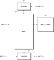
- a deployment such as a communication system configured by a macro base station apparatus and an RRH, and a coverage supported by the macro base station apparatus including a part or all of the coverage supported by the RRH is a heterogeneous network deployment. Called.
- the mobile station apparatus can perform single cell communication with the macro base station apparatus or RRH. That is, a certain mobile station apparatus communicates with a macro base station apparatus or RRH without using cooperative communication, and transmits and receives signals.
- the macro base station apparatus receives an uplink signal from a mobile station apparatus that is close in distance to itself.
- the RRH receives an uplink signal from a mobile station apparatus that is close in distance to the own apparatus.
- the mobile station apparatus is located near the edge of the coverage constructed by the RRH (cell edge), it is necessary to take measures against co-channel interference from the macro base station apparatus.
- the mobile station apparatus receives signals transmitted from both the macro base station apparatus and the RRH using cooperative communication.
- the mobile station apparatus receives either the macro base station apparatus or the RRH. Therefore, it is considered to transmit a signal in a suitable form.
- the mobile station apparatus transmits an uplink signal with transmission power suitable for reception of a signal by the macro base station apparatus.
- the mobile station apparatus transmits an uplink signal with transmission power suitable for receiving a signal by RRH. Thereby, unnecessary interference in the uplink can be reduced and the frequency utilization efficiency can be improved.
- a reference signal for a plurality of base station apparatuses and a plurality of RRHs corresponding to LTE-A to apply a precoding process to a new control channel signal and demodulate the new control channel signal
- the application of the same precoding processing to Reference is also under consideration.
- a plurality of PRB pairs are configured as an area where EPDCCH (Enhanced Physical Downlink Channel) may be arranged, and one EPDCCH is configured as EPDCCH.
- EPDCCH Enhanced Physical Downlink Channel
- the total number of antenna ports that transmit reference signals used for demodulation of signals allocated to the EPDCCH, which are allocated in the PRB is four, one PRB pair is divided into four resources.
- a communication method that is composed of one or more sets of resources obtained by dividing a pair and is used for a base station apparatus that communicates with a plurality of mobile station apparatuses using the EPDCCH, and constitutes one PRB pair
- the total number of antenna ports that transmit reference signals used for demodulation of signals allocated to the EPDCCH, which are allocated to the PRBs of each of the PRBs, is four
- one PRB pair is divided into four Reference signals used for demodulation of signals arranged on the EPDCCH, each of which corresponds to an antenna port of a different number and is arranged in the PRB of each of the two PRBs constituting one PRB pair.
- a plurality of PRB pairs are configured as an area in which the integrated circuit of the present invention, EPDCCH (Enhanced Physical Downlink Control Channel) may be arranged, and the EPDCCH1 includes the above-described EPDCB1.
- EPDCCH Enhanced Physical Downlink Control Channel
- the mobile station apparatus 5 receives signals transmitted from both the base station apparatus 3 and the RRH 4 using cooperative communication in the downlink, and either the base station apparatus 3 or the RRH 4 in the uplink.
- the signal may be transmitted in a suitable form.
- the mobile station apparatus 5 transmits an uplink signal with transmission power suitable for receiving a signal by the base station apparatus 3.
- the mobile station apparatus 5 transmits an uplink signal with transmission power suitable for receiving a signal by the RRH 4.
- a scheduling request (Scheduling request: SR) or the like is used.
- Other physical channel types include synchronization channel used for downlink synchronization establishment (Synchronization CHannel: ⁇ SCH), physical random access channel used for uplink synchronization establishment (Physical Random Access CHannel: PRACH)
- a physical broadcast channel (Physical (Broadcast CHannel: PBCH) used for transmission of downlink system information (SIB: SISystem Information Block) is also used.
- the PDSCH is also used for transmission of downlink system information.
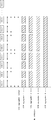
- FIG. 10 is a diagram illustrating a schematic configuration of a downlink time frame from the base station apparatus 3 or the RRH 4 to the mobile station apparatus 5 according to the embodiment of the present invention.
- the horizontal axis represents the time domain
- the vertical axis represents the frequency domain.
- the downlink time frame is a unit for resource allocation and the like, and is a resource block (RB) (physical resource block; also referred to as a PRB: Physical Resource Block) composed of a frequency band and a time slot having a predetermined downlink width. .)) (Physical resource block pair; referred to as PRB pair).
- RB resource block
- PRB Physical Resource Block
- PRB pair Physical resource block pair
- One downlink PRB pair (downlink physical resource block pair; referred to as DL PRB pair) is referred to as two consecutive PRBs (downlink physical resource block; DL PRB in the downlink time domain). ).
- the second type reference signal is used for demodulation of the PDSCH and the second PDCCH, and is also referred to as UE-specific RS.
- the third type of reference signal is used only for estimating propagation path fluctuations, and is also referred to as Channel State Information RS: CSI-RS.
- the downlink reference signal is a known signal in the communication system 1. Note that the number of downlink resource elements constituting the downlink reference signal may depend on the number of transmission antennas (antenna ports) used for communication to the mobile station apparatus 5 in the base station apparatus 3 and RRH4.
- CRS is used as the first type reference signal
- UE-specific RS is used as the second type reference signal
- CSI-RS is used as the third type reference signal.
- the UE-specific RS can also be used for demodulation of PDSCH to which cooperative communication is applied and PDSCH to which cooperative communication is not applied.
- the UE-specific RS can also be used for demodulation of the second PDCCH to which cooperative communication (precoding processing) is applied and the second PDCCH to which cooperative communication is not applied.
- PDCCH (first PDCCH or second PDCCH) is information indicating allocation of DL PRB (DL PRB pair) to PDSCH, information indicating allocation of UL PRB (UL PRB pair) to PUSCH, mobile station identifier (Radio) Network Temporary Identifier: RNTI)), a signal generated from control information such as modulation scheme, coding rate, retransmission parameter, spatial multiplexing number, precoding matrix, information indicating transmission power control command (TPC command) Be placed.
- Control information included in the PDCCH is referred to as downlink control information (Downlink Control DCI).
- DCI including information indicating assignment of DL PRB (DL PRB pair) to PDSCH is referred to as downlink assignment (also referred to as “downlink assignment” or “downlink assignment”) and UL PRB (UL PRB pair) to PUSCH.
- the DCI including the information indicating the allocation is referred to as an uplink grant (uplink grant: UL grant).
- the downlink assignment includes a transmission power control command for PUCCH.
- the uplink assignment includes a transmission power control command for PUSCH.
- One PDCCH includes only information indicating resource allocation of one PDSCH, or information indicating resource allocation of one PUSCH, and information indicating resource allocation of a plurality of PDSCHs, It does not include information indicating PUSCH resource allocation.
- CRC Cyclic Redundancy Check
- RNTI Cyclic Redundancy Check
- a CRC code is generated from DCI using a predetermined generator polynomial.
- the generated CRC code is subjected to exclusive OR (also referred to as scrambling) processing using RNTI.
- exclusive OR also referred to as scrambling
- a signal obtained by modulating a bit indicating DCI and a bit (CRC masked by UE ID) generated by performing exclusive OR processing on the CRC code using RNTI is actually transmitted on PDCCH. Is done.
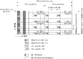
- FIG. 11 is a diagram illustrating an example of the arrangement of downlink reference signals in a downlink subframe of the communication system 1 according to the embodiment of the present invention.
- FIG. 11 illustrates the arrangement of downlink reference signals in a single DL PRB pair.
- a common arrangement method is used in a plurality of DL PRB pairs in the downlink system band. .
- R0 to R1 indicate CRS of antenna ports 0 to 1, respectively.
- the antenna port means a logical antenna used in signal processing, and one antenna port may be composed of a plurality of physical antennas. A plurality of physical antennas constituting the same antenna port transmit the same signal.
- delay diversity or CDD Cyclic Delay Delay
- FIG. 11 shows a case where CRS corresponds to two antenna ports, but the communication system of the present embodiment may support different numbers of antenna ports, for example, one antenna port or four antenna ports.
- the CRS for the antenna port may be mapped to a downlink resource.
- the CRS can be arranged in all DL PRB pairs in the downlink system band.
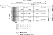
- FIG. 12 is a diagram illustrating an example of arrangement of downlink reference signals in a downlink subframe of the communication system 1 according to the embodiment of the present invention.
- D1 and D2 indicate UE-specific RSs.
- FIG. 12 shows that the number of antenna ports used for UE-specific RS transmission is three (antenna port 7, antenna port 8, and antenna port 9) or four (antenna port 7, antenna port 8, and antenna port 9).
- An example of UE-specific RS arrangement in the case of antenna port 10) is shown.
- each of the base station apparatus 3 and the RRH 4 may assign a CRS signal to different downlink resource elements, or may assign a CRS signal to the same downlink resource element. For example, when the cell IDs notified from the base station apparatus 3 and the RRH 4 are different, CRS signals may be assigned to different downlink resource elements. In another example, only the base station apparatus 3 allocates CRS signals to some downlink resource elements, and the RRH 4 may not allocate CRS signals to any downlink resource elements. For example, when the cell ID is notified only from the base station apparatus 3, a CRS signal may be assigned as described above.
- CSI-RSs of CSI ports 3 and 4 are code division multiplexed and mapped.
- CSI-RS CDM group C3 CSI-RSs of CSI ports 5 and 6 (antenna ports 19 and 20) are code-division multiplexed and mapped.
- CDM group C4 of CSI-RS CSI-RS of CSI ports 7 and 8 (antenna ports 21 and 22) are code division multiplexed and mapped.
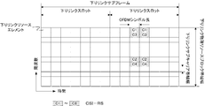
- FIG. 14 is a diagram illustrating a schematic configuration of an uplink time frame from the mobile station apparatus 5 to the base station apparatus 3 and the RRH 4 according to the embodiment of the present invention.
- the horizontal axis represents the time domain
- the vertical axis represents the frequency domain.
- An uplink time frame is a unit for resource allocation and the like, and is a pair of physical resource blocks (uplink physical resource block pair; UL PRB pair) consisting of a frequency band and a time zone of a predetermined width of the uplink. ).
- One UL PRB pair is composed of two uplink PRBs (uplink physical resource block; referred to as UL PRB) that are continuous in the uplink time domain.
- PUCCH format 1b uses QPSK (Quadrature Shift Phase Key Shift) as a modulation method for modulating information about ACK / NACK.
- QPSK Quadrature Shift Phase Key Shift
- PUCCH format 1b 2-bit information is indicated from the modulation signal.
- the PUCCH used for SR transmission is called PUCCH format 1.
- the PUCCH used for CQI transmission is referred to as PUCCH format 2.
- the PUCCH used for simultaneous transmission of CQI and ACK / NACK is referred to as PUCCH format 2a or PUCCH format 2b.
- the reference signal (DM RS) of the uplink pilot channel is multiplied by a modulation signal generated from ACK / NACK information.
- PUCCH format 2a 1-bit information about ACK / NACK and CQI information are transmitted.
- PUCCH format 2b 2-bit information on ACK / NACK and CQI information are transmitted.
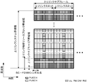
- the DM RS When the DM RS is arranged in the same UL PRB as the PUSCH, it is arranged in the fourth SC-FDMA symbol in the uplink slot.
- the DM RS When the DM RS is arranged in the same UL PRB as the PUCCH including ACK / NACK, the DM RS is arranged in the third, fourth, and fifth SC-FDMA symbols in the uplink slot.
- the DM RS is arranged in the same UL PRB as the PUCCH including the SR, the DM RS is arranged in the third, fourth, and fifth SC-FDMA symbols in the uplink slot.
- the DM RS When the DM RS is arranged in the same UL PRB as the PUCCH including the CQI, it is arranged in the second and sixth SC-FDMA symbols in the uplink slot.
- code multiplexing in the frequency domain and code multiplexing in the time domain are used in the PUCCH.
- Code multiplexing in the frequency domain is processed by multiplying each code of the code sequence by a modulated signal modulated from uplink control information in subcarrier units.
- Code multiplexing in the time domain is processed by multiplying each code of the code sequence by the modulated signal modulated from the uplink control information in units of SC-FDMA symbols.
- a plurality of PUCCHs are arranged in the same UL PRB, and different codes are assigned to the respective PUCCHs, and code multiplexing is realized in the frequency domain or time domain by the assigned codes.
- the PUSCH resource is an uplink subframe after a predetermined number (for example, 4) from the downlink subframe in which the PDCCH resource including the uplink grant used for allocation of the PUSCH resource is arranged in the time domain. Placed in.
- the CCE aggregation number configuring the first PDCCH is set in the base station apparatus 3 according to the coding rate set in the first PDCCH and the number of bits of DCI included in the first PDCCH.
- a set of n CCEs is hereinafter referred to as “CCE aggregation n”.
- a plurality of downlink resource elements constituting a CCE is configured by a plurality of resource element groups (also referred to as REG and mini-CCE).
- the resource element group is composed of a plurality of downlink resource elements.
- one resource element group is composed of four downlink resource elements.
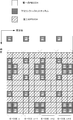
- FIG. 16 is a diagram illustrating an arrangement example of resource element groups in a downlink radio frame of the communication system 1 according to the embodiment of the present invention.
- the resource element group used for the first PDCCH is shown, and illustrations and descriptions of unrelated parts (PDSCH, second PDCCH, UE-specific RS, CSI-RS) are omitted.
- one resource element group is configured by four downlink resource elements adjacent in the frequency domain.
- FIG. 16 it shows that the downlink resource element to which the same code
- resource element R0 (downlink reference signal for antenna port 0) and R1 (downlink reference signal for antenna port 1) in which downlink reference signals are arranged are skipped to form a resource element group.
- numbering symbol “1” is performed from the resource element group of the first OFDM symbol having the lowest frequency, and then the resource element group of the second OFDM symbol having the lowest frequency is numbered.
- CCE is composed of a plurality of resource element groups shown in FIG.
- one CCE is composed of nine different resource element groups distributed in the frequency domain and the time domain.
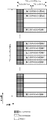
- one second PDCCH region is composed of a plurality of DL PRB pairs, it may be composed of DL PRB pairs dispersed in the frequency domain, or may be composed of DL PRB pairs that are continuous in the frequency domain.
- the base station device 3 can configure the second PDCCH region for each of the plurality of mobile station devices 5.
- an E-CCE aggregation number having a large number of E-CCEs constituting the second PDCCH is used. Also, for example, when the base station device 3 transmits DCI with a small number of bits, when using an E-CCE aggregation number with a small number of E-CCEs constituting the second PDCCH and transmits DCI with a large number of bits. The E-CCE aggregation number having a large number of E-CCEs constituting the second PDCCH is used.
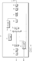
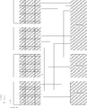
- FIG. 20 is a diagram showing an example of the configuration of the E-CCE according to the embodiment of the present invention. Compared with the example shown in FIG. 19, the number of antenna ports of UE-specific RS is different, and three or four transmission antennas (antenna port 7, antenna port 8, antenna port 9, antenna port 10, not shown) A case where UE-specific RS (D1, D2) is arranged is shown.
- E-CCEs that make up one Distributed E-PDCCH use E-CCEs with different E-CCE numbers (different frequency positions) in each DL PRB pair.
- the Distributed E-PDCCH may be configured. For example, E-CCE with the smallest E-CCE number within a certain DL PRB pair (lowest in the frequency domain) and E-CCE number within a certain DL PRB pair are second smallest (second in frequency) (Low) E-CCE, E-CCE number is the third smallest (third lowest in frequency) in a DL PRB pair, and E-CCE number is fourth in a certain DL PRB pair
- a single distributed E-PDCCH may be configured from an E-CCE having the smallest (fourth lowest in frequency) (the highest E-CCE number) (the highest in the frequency domain).
- E-CCE aggregation number candidates (candidate combinations) for the localized E-PDCCH, the number of UE-specific RS antennas, and each E-CCE May be associated in advance with the relationship of the antenna to which.
- the base station apparatus 3 indicates only information on candidates for the E-CCE aggregation number for the localized E-PDCCH to the mobile station apparatus 5 using RRC signaling, and the mobile station apparatus 5 displays the E-CCE aggregation for the E-PDCCH.
- the number of UE-specific RS antennas and the relationship between the antennas corresponding to each E-CCE are recognized from information on the number candidates.
- the base station apparatus 3 shows only information indicating the number of UE-specific RS antennas in the second PDCCH region to which the first physical resource mapping is applied to the mobile station apparatus 5 using RRC signaling,
- the device 5 recognizes the relationship between the E-CCE aggregation number candidate for the localized E-PDCCH and the antenna corresponding to each E-CCE from the information indicating the number of UE-specific RS antennas.
- UE-specific RSs of four transmission antennas are arranged.
- the UE-specific RS of one transmission antenna is arranged.
- two transmit antennas are used when transmission diversity such as SFBC (Space Frequency Block Coding) is applied to the distributed E-PDCCH. 7.
- the UE-specific RS of the antenna port 8) may be arranged.
- different second PDCCH candidates are composed of different E-CCEs (including one E-CCE and a plurality of E-CCEs).
- the E-CCEs constituting the plurality of second PDCCH candidates of the search space set in the second PDCCH region to which the first physical resource mapping is applied are a plurality of E-CCEs having consecutive E-CCE numbers. is there.
- the E-CCEs constituting the plurality of second PDCCH candidates of the search space set in the second PDCCH region to which the second physical resource mapping is applied are a plurality of non-consecutive E-CCEs having E-CCE numbers. It is.
- the first E-CCE number used for the search space in the second PDCCH region is set for each mobile station apparatus 5.
- the first E-CCE number used for the search space is set by a random function using an identifier (mobile station identifier) assigned to the mobile station device 5.
- the base station apparatus 3 notifies the mobile station apparatus 5 of the first E-CCE number used for the search space using RRC signaling.
- the number of second PDCCH candidates for the first Search space may be different from the number of second PDCCH candidates for the second Search space.
- the second PDCCH to which precoding processing is applied is basically used, and when it is difficult for the base station apparatus 3 to realize precoding processing more suitable for some situation, the precoding processing is not applied, and the frequency
- the number of second PDCCH candidates in the first search space is set larger than the number of second PDCCH candidates in the second search space. May be.
- the number of second PDCCH candidates for the search space in one second PDCCH region can be varied. For example, as the number of second PDCCH regions configured in the mobile station device 5 increases, the number of second PDCCH candidates for the search space in one second PDCCH region is decreased.
- the reception processing unit 101 detects (receives) a preamble sequence from the received PRACH signal received from the mobile station apparatus 5 by the reception antenna 109 in accordance with the instruction of the control unit 105.
- the reception processing unit 101 also estimates arrival timing (reception timing) along with detection of the preamble sequence.
- the reception processing unit 101 performs processing of detecting a preamble sequence for an uplink subframe, UL PRB pair, to which the device itself has assigned PRACH resources.
- the reception processing unit 101 outputs information regarding the estimated arrival timing to the control unit 105.
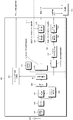
- the data modulation unit 221 uses the data encoded by the turbo coding unit 219 as a modulation method input from the control unit 105, for example, QPSK (quadrature phase shift keying; Quadrature Phase Shift Keying), 16QAM (16-value quadrature amplitude modulation). Modulation is performed using a modulation scheme such as 16 Quadrature Amplitude Modulation) or 64QAM (64-value quadrature amplitude modulation; 64 Quadrature Amplitude Modulation) to generate a signal sequence of modulation symbols.
- the data modulation unit 221 outputs the generated signal sequence to the precoding processing unit 229.
- a UE-specific RS for which precoding processing is not performed in the precoding processing unit 231 is UE-specific RS in the DL PRB pair used for the second PDCCH in the second PDCCH region of the second physical resource mapping. It is.
- the precoding processing unit 231 performs precoding processing on a part of the UE-specific RS input from the downlink pilot channel processing unit 205 and outputs the result to the multiplexing unit 207.
- the UE-specific RS for which precoding processing is performed by the precoding processing unit 231 is a UE-specific RS in the DL PRB pair used for the second PDCCH in the second PDCCH region of the first physical resource mapping. is there.
- Multiplexer 207 receives a signal input from downlink pilot channel processor 205, a signal input from each physical downlink shared channel processor 201, and a signal input from each physical downlink control channel processor 203. Are multiplexed into the downlink subframe according to the instruction from the control unit 105. Control signals related to DL PRB pair allocation to the PDSCH set by the radio resource control unit 103, resource allocation to the PDCCH (first PDCCH, second PDCCH), and physical resource mapping in the second PDCCH region The control unit 105 controls the processing of the multiplexing unit 207 based on the control signal.
- the subcarrier demapping unit 315 separates the signal demodulated by the FFT unit 313 into DM RS, SRS, PUSCH signal, and PUCCH signal based on the control signal input from the control unit 105.
- the subcarrier demapping unit 315 outputs the separated DM RS to the propagation path estimation unit 317, outputs the separated SRS to the SRS processing unit 333, and outputs the separated PUSCH signal to the PUSCH propagation path equalization unit 319.
- the separated PUCCH signal is output to the PUCCH channel equalization unit 321.
- the propagation path estimation unit 317 estimates propagation path fluctuations using the DM RS separated by the subcarrier demapping unit 315 and a known signal.
- the propagation path estimation unit 317 outputs the estimated propagation path estimation value to the PUSCH propagation path equalization unit 319 and the PUCCH propagation path equalization unit 321.
- the PUSCH channel equalization unit 319 equalizes the amplitude and phase of the PUSCH signal separated by the subcarrier demapping unit 315 based on the channel estimation value input from the channel estimation unit 317.
- equalization refers to a process for restoring the fluctuation of the propagation path received by the signal during wireless communication.
- PUSCH propagation path equalization section 319 outputs the adjusted signal to IDFT section 323.
- the reception processing unit 401 measures downlink reception quality (RSRP: “Reference” Signal “Received Power”) and outputs the measurement result to the control unit 405.
- the reception processing unit 401 measures (calculates) RSRP from CRS or CSI-RS based on an instruction from the control unit 405. Details of the reception processing unit 401 will be described later.
- the PDCCH channel compensation unit 519 adjusts the amplitude and phase of the PDCCH signal separated by the demultiplexing unit 511 according to the channel compensation value input from the channel estimation unit 513.
- the channel compensation unit 519 for PDCCH adjusts the second PDCCH signal according to the channel compensation value generated based on the UE-specific RS by the channel estimation unit 513, and performs the first PDCCH signal transmission.
- the signal is adjusted according to the channel compensation value generated based on the CRS by the channel estimation unit 513 with respect to the signal.
- the PDCCH propagation path compensation unit 519 designates each E-CCE signal in the DL PRB pair in the second PDCCH region from the control unit 405, and transmits a corresponding transmission antenna (antenna port) to each E-CCE. ) According to the propagation path compensation value generated based on UE-specific RS. PDCCH propagation path compensation section 519 outputs the adjusted signal to PDCCH demapping section 533.
- the physical downlink control channel decoding unit 521 demodulates and decodes the signal input from the PDCCH channel compensation unit 519 as described below, and detects control data.
- the QPSK demodulator 527 performs QPSK demodulation on the PDCCH signal and outputs the result to the Viterbi decoder 529.
- the Viterbi decoder unit 529 decodes the signal demodulated by the QPSK demodulator 527 and outputs the decoded DCI to the controller 405.
- this signal is expressed in bit units, and the Viterbi decoder unit 529 also performs rate dematching in order to adjust the number of bits for which Viterbi decoding processing is performed on the input bits.
- the number of candidates for the second PDCCH may be different.
- the number of second PDCCH candidates in the search space (search space for the second PDCCH) of the second PDCCH region to which the first physical resource mapping is applied is the second number to which the second physical resource mapping is applied.
- the number may be larger than the number of second PDCCH candidates in the search space of the PDCCH region (search space for the second PDCCH).
- the number of second PDCCH candidates in the search space of the second PDCCH region to which the first physical resource mapping is applied (the search space for the second PDCCH)
- the second The number of second PDCCH candidates in the search space (search space for the second PDCCH) of the second PDCCH region to which the physical resource mapping is applied is the same.
- the number of second PDCCH candidates in the search space (search space for the second PDCCH) of the second PDCCH region to which physical resource mapping is applied, and the second PDCCH region to which the second physical resource mapping is applied Search space (second PDCCH The number of second PDCCH candidates of Search space) of may be different.
- the random access channel processing unit 629 generates a signal to be transmitted by PRACH using the preamble sequence instructed by the control unit 405, and outputs the generated signal to the transmission power adjustment unit 627.
- the transmission power adjustment unit 627 adjusts the transmission power based on the control signal from the control unit 405 with respect to the signal input from the GI insertion unit 625 or the signal input from the random access channel processing unit 629, and performs D / Output to A section 605.
- the transmission power adjustment unit 627 controls the average transmission power of PUSCH, PUCCH, DM RS, SRS, and PRACH for each uplink subframe.
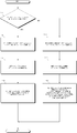
- FIG. 7 shows the setting of the search space in the second PDCCH region of the mobile station apparatus 5 according to the embodiment of the present invention, the setting of the number of UE-specific RS transmission antennas in the DL PRB pair, and the DL PRB pair.
- It is a flowchart which shows an example of the process in connection with the setting of UE-specific RS used for the demodulation of each E-CCE.
- an example of processing in the second PDCCH region to which the first physical resource mapping is applied will be described.
- a case where there are two types of candidate sets of E-CCE aggregation number (first candidate set and second candidate set) is shown.
- first number and second number a case where there are two types of UE-specific RS transmission antennas in the DL PRB pair (first number and second number) is shown.
- the first number is two.
- the second number is four.
- the third number and the fourth number may be further configured.
- the third number is 1.
- the fourth number is three.
- the mobile station apparatus 5 divides each E-CCE signal in the DL PRB pair into a plurality of groups, and assigns each E-CCE signal in the same group to a UE-specific corresponding to a common transmission antenna.
- Demodulation is performed using RS, and signals of different groups of E-CCEs (E-CCEs) are set to be demodulated using UE-specific RSs corresponding to different transmission antennas (step S107).
- the signal modulated from the downlink control data is arranged as compared to the case where the UE-specific RS transmission antenna is the first number. -The number of downlink resource elements in the CCE is large.
- FIG. 8 shows the setting of the search space in the second PDCCH region of the base station apparatus 3 according to the embodiment of the present invention, the setting of the number of UE-specific RS transmission antennas in the DL PRB pair, and the DL PRB pair.
- an example of processing in the second PDCCH region to which the first physical resource mapping is applied will be described.
- a case where there are two types of candidate sets of E-CCE aggregation number is shown.
- a signal modulated from downlink control data may be arranged as compared to the case of the first number of UE-specific RS transmission antennas.
- the base station apparatus 3 determines which (including all) E-CCE signal to transmit the second PDCCH for each downlink subframe. Schedule.
- the base station apparatus 3 has the first number (for example, 4) of antenna ports (UE-specific RS antenna ports) Control to transmit signals of each first element (E-CCE) in the physical resource block pair (PRB pair) using different antenna ports (antenna ports used for transmitting UE-specific RS) If the number of antenna ports (UE-specific RS antenna ports) is the second number (for example, two), a plurality of first elements (E-CCE) in the physical resource block pair (PRB pair) Of a plurality of groups (for example, two groups.
- Each group includes two E-CCEs) ) And transmit signals of each first element (E-CCE) in the same group using a common antenna port (antenna port also used for transmitting UE-specific RS), and different groups
- the first element (E-CCE) is controlled to be transmitted using different antenna ports (antenna ports used for transmitting UE-specific RS).
- the mobile station device 5 is configured such that when the number of antenna ports (UE-specific RS antenna ports) is the first number (for example, four), The reference signal (UE-specific RS) corresponding to each different antenna port (UE-specific RS antenna port) is used for each first element (E-CCE) signal in the physical resource block pair (PRB pair).
- the base station apparatus 3 substantially performs precoding processing on a signal for each minimum unit (one E-CCE or a plurality of E-CCEs) of E-CCE used for the mobile station apparatus 5.
- the mobile station apparatus 5 can receive the second PDCCH signal that has been subjected to the precoding process in the base station apparatus 3, and the second PDCCH characteristic received by the mobile station apparatus 5 can be received. Improvements can be made.
- the program when distributing to the market, can be stored and distributed on a portable recording medium, or transferred to a server computer connected via a network such as the Internet.
- the storage device of the server computer is also included in the present invention.
- LSI which is typically an integrated circuit.
- Each functional block of the mobile station device 5 and the base station device 3 may be individually chipped, or a part or all of them may be integrated into a chip.
- the method of circuit integration is not limited to LSI, and may be realized by a dedicated circuit or a general-purpose processor.
- an integrated circuit based on the technology can also be used.
- Each functional block of the mobile station device 5 and the base station device 3 may be realized by a plurality of circuits.
- a plurality of physical resource block pairs are configured as a control channel region, which is a region where a control channel may be arranged, and a first resource block is divided from the resources obtained by dividing one physical resource block pair.
- Base station apparatus 4 (A to C) RRH 5 (A to C) mobile station apparatus 101 reception processing unit 103 radio resource control unit 105 control unit 107 transmission processing unit 109 reception antenna 111 transmission antenna 201 physical downlink shared channel processing unit 203 physical downlink control channel processing unit 205 downlink Pilot channel processing section 207 Multiplexing section 209 IFFT section 211 GI insertion section 213 D / A section 215 Transmission RF section 219 Turbo coding section 221 Data modulation section 223 Convolution coding section 225 QPSK modulation section 227 Precoding processing section (for PDCCH) 229 Precoding processing unit (for PDSCH) 231 Precoding processing unit (for downlink pilot channel) 301 reception RF unit 303 A / D unit 309 symbol timing detection unit 311 GI removal unit 313 FFT unit 315 subcarrier demapping unit 317 propagation channel estimation unit 319 propagation channel equalization unit (for PUSCH) 321 Channel equalization unit (for PUCCH) 323 IDFT unit 325 Data demodulation unit
Landscapes
- Engineering & Computer Science (AREA)
- Signal Processing (AREA)
- Computer Networks & Wireless Communication (AREA)
- Mobile Radio Communication Systems (AREA)
- Radio Transmission System (AREA)
Abstract
La présente invention permet de transmettre et de recevoir de manière efficace des signaux, tels que des informations de commande, entre un dispositif de station de base et un dispositif de station mobile. Un canal physique amélioré de commande en liaison descendante (E-PDCCH) est configuré à partir d'une ressource ou d'un ensemble de plusieurs ressources dans lesquelles est divisée une paire de blocs de ressources physiques (PRB). Dans les cas où le nombre total de ports d'antenne destinés à transmettre des signaux de référence utilisés lors de la démodulation des signaux agencés dans le canal E-PDCCH est 4, chaque ressource dans laquelle la seule paire de blocs PRB est divisée en 4, correspond à un nombre différent de port d'antenne et une détection de décodage est effectuée. Dans les cas où le nombre total de ports d'antenne destinés à transmettre des signaux de référence utilisés lors de la démodulation des signaux agencés dans le canal E-PDCCH est 4, chaque ressource dans laquelle la seule paire de blocs PRB est divisée en 2, correspond à un nombre différent de port d'antenne et une détection de décodage est effectuée. La présente invention comprend une unité de traitement de réception qui effectue la détection de décodage et qui démodule les signaux agencés dans le canal EPDCCH à l'aide des signaux de référence transmis depuis les ports d'antenne correspondant aux ressources utilisées comme le canal EPDCCH.
Priority Applications (1)
| Application Number | Priority Date | Filing Date | Title |
|---|---|---|---|
| US14/364,576 US9445412B2 (en) | 2011-12-12 | 2012-12-07 | Mobile station apparatus, base station apparatus, and communication method |
Applications Claiming Priority (2)
| Application Number | Priority Date | Filing Date | Title |
|---|---|---|---|
| JP2011270776A JP5843390B2 (ja) | 2011-12-12 | 2011-12-12 | 通信システム、移動局装置、基地局装置、通信方法および集積回路 |
| JP2011-270776 | 2011-12-12 |
Publications (1)
| Publication Number | Publication Date |
|---|---|
| WO2013089021A1 true WO2013089021A1 (fr) | 2013-06-20 |
Family
ID=48612473
Family Applications (1)
| Application Number | Title | Priority Date | Filing Date |
|---|---|---|---|
| PCT/JP2012/081740 WO2013089021A1 (fr) | 2011-12-12 | 2012-12-07 | Système de communication, dispositif de station mobile, dispositif de station de base, procédé de communication et circuit intégré |
Country Status (3)
| Country | Link |
|---|---|
| US (1) | US9445412B2 (fr) |
| JP (1) | JP5843390B2 (fr) |
| WO (1) | WO2013089021A1 (fr) |
Families Citing this family (16)
| Publication number | Priority date | Publication date | Assignee | Title |
|---|---|---|---|---|
| WO2014117326A1 (fr) | 2013-01-29 | 2014-08-07 | Panasonic Intellectual Property Corporation Of America | Station de base, terminal, procédé d'émission et procédé de réception |
| TW201507497A (zh) * | 2013-04-03 | 2015-02-16 | Interdigital Patent Holdings | 針對一個或多個載波類型的epdcch共用檢索空間設計 |
| JP6297293B2 (ja) * | 2013-10-09 | 2018-03-20 | 株式会社Nttドコモ | 無線装置、無線制御装置及び通信制御方法 |
| CN111405665B (zh) * | 2013-12-11 | 2023-12-12 | 北京三星通信技术研究有限公司 | 物理下行控制信道的资源分配方法和装置 |
| CN107078770B (zh) * | 2014-10-09 | 2020-10-16 | Lg 电子株式会社 | 支持大规模mimo的无线通信系统中的参考信号产生方法 |
| US20160316513A1 (en) * | 2015-04-23 | 2016-10-27 | Samsung Electronics Co., Ltd. | Communication device and method for controlling the same |
| EP3292647B1 (fr) * | 2015-05-06 | 2021-07-07 | Telefonaktiebolaget LM Ericsson (publ) | Insertion et extraction de données de commande à l'aide de composantes de fréquence |
| EP3350951B1 (fr) * | 2015-09-17 | 2021-10-27 | Apple Inc. | Transmission d'informations de commande de liaison montante dans des systèmes sans fil |
| JP2019016824A (ja) * | 2015-11-27 | 2019-01-31 | シャープ株式会社 | 端末装置、基地局装置および通信方法 |
| WO2017134273A1 (fr) * | 2016-02-05 | 2017-08-10 | Sony Corporation | Dispositif terminal, équipement d'infrastructure, procédés, et montage de circuits intégrés |
| CN109792701B (zh) * | 2016-08-10 | 2022-12-30 | 交互数字专利控股公司 | 降低等待时间的系统中的定时提前和处理能力 |
| CN107846373B (zh) * | 2016-09-20 | 2021-02-12 | 华为技术有限公司 | 发送或接收物理下行控制信道的方法和设备 |
| CN112165374B (zh) * | 2016-09-28 | 2023-01-06 | Oppo广东移动通信有限公司 | 传输数据的方法、信道估计的方法和装置 |
| CN107896388B (zh) * | 2016-09-29 | 2021-12-31 | 华为技术有限公司 | 下行控制信道的传输方法、接收网元及发送网元 |
| CN112654095B (zh) * | 2017-01-05 | 2022-10-25 | 华为技术有限公司 | 传输数据的方法、网络设备和终端设备 |
| SG11201909844XA (en) | 2017-05-04 | 2019-11-28 | Panasonic Ip Corp America | User equipment and method therefor |
Family Cites Families (4)
| Publication number | Priority date | Publication date | Assignee | Title |
|---|---|---|---|---|
| CA2786804C (fr) * | 2010-01-11 | 2016-09-06 | Research In Motion Limited | Systeme et procede permettant une gestion des interferences de canal de commande et canal physique de commande de liaison descendante (pdcch) etendu |
| JP5784152B2 (ja) * | 2011-02-11 | 2015-09-24 | インターデイジタル パテント ホールディングス インコーポレイテッド | 拡張された制御チャネルのシステムおよび方法 |
| US8923201B2 (en) * | 2011-06-15 | 2014-12-30 | Samsung Electronics Co., Ltd. | Extension of physical downlink control signaling in a communication system |
| US20130064216A1 (en) * | 2011-09-12 | 2013-03-14 | Research In Motion Limited | DMRS Association and Signaling for Enhanced PDCCH in LTE Systems |
-
2011
- 2011-12-12 JP JP2011270776A patent/JP5843390B2/ja active Active
-
2012
- 2012-12-07 US US14/364,576 patent/US9445412B2/en active Active
- 2012-12-07 WO PCT/JP2012/081740 patent/WO2013089021A1/fr active Application Filing
Non-Patent Citations (2)
| Title |
|---|
| NTT DOCOMO: "DM-RS Design for E-PDCCH in Rel-11", 3GPP TSG RAN WG1 MEETING #67 RL-114302, 18 November 2011 (2011-11-18) * |
| NTT DOCOMO: "Enhanced PDCCH for DL MIMO in Rel- 11", 3GPP TSG RAN WG1 MEETING #65 RL-112436, 26 August 2011 (2011-08-26) * |
Also Published As
| Publication number | Publication date |
|---|---|
| JP5843390B2 (ja) | 2016-01-13 |
| US9445412B2 (en) | 2016-09-13 |
| JP2013123140A (ja) | 2013-06-20 |
| US20140341145A1 (en) | 2014-11-20 |
Similar Documents
| Publication | Publication Date | Title |
|---|---|---|
| JP5990793B2 (ja) | 端末装置、基地局装置、通信方法および集積回路 | |
| JP5832914B2 (ja) | 通信システム、移動局装置、基地局装置、通信方法および集積回路 | |
| JP5843390B2 (ja) | 通信システム、移動局装置、基地局装置、通信方法および集積回路 | |
| US9609638B2 (en) | Mobile station apparatus, base station apparatus, and communication method | |
| JP5935148B2 (ja) | 移動局装置、基地局装置、通信方法および集積回路 | |
| JP5832913B2 (ja) | 通信システム、移動局装置、基地局装置、通信方法および集積回路 | |
| JP5866014B2 (ja) | 基地局装置、移動局装置、通信方法、および集積回路 | |
| JP5886639B2 (ja) | 通信システム、移動局装置、基地局装置、通信方法および集積回路 | |
| JP2014011540A (ja) | 通信システム、移動局装置、基地局装置、通信方法および集積回路 | |
| JP2014023073A (ja) | 通信システム、移動局装置、基地局装置、通信方法および集積回路 | |
| JP5957732B2 (ja) | 通信システム、移動局装置、基地局装置、通信方法および集積回路 | |
| JP5868717B2 (ja) | 通信システム、移動局装置、基地局装置、通信方法および集積回路 | |
| JP2013192142A (ja) | 通信システム、移動局装置、基地局装置、通信方法および集積回路 | |
| JP2013102320A (ja) | 通信システム、移動局装置、基地局装置、通信方法および集積回路 | |
| JP2013150231A (ja) | 通信システム、移動局装置、基地局装置、通信方法および集積回路 | |
| JP2013255136A (ja) | 通信システム、移動局装置、基地局装置、通信方法および集積回路 | |
| JP2013192141A (ja) | 通信システム、移動局装置、基地局装置、通信方法および集積回路 | |
| JP2013192144A (ja) | 通信システム、移動局装置、基地局装置、通信方法および集積回路 | |
| JP2013123138A (ja) | 通信システム、移動局装置、基地局装置、通信方法および集積回路 | |
| JP2014022762A (ja) | 通信システム、移動局装置、基地局装置、通信方法および集積回路 |
Legal Events
| Date | Code | Title | Description |
|---|---|---|---|
| 121 | Ep: the epo has been informed by wipo that ep was designated in this application |
Ref document number: 12858654 Country of ref document: EP Kind code of ref document: A1 |
|
| DPE1 | Request for preliminary examination filed after expiration of 19th month from priority date (pct application filed from 20040101) | ||
| WWE | Wipo information: entry into national phase |
Ref document number: 14364576 Country of ref document: US |
|
| NENP | Non-entry into the national phase |
Ref country code: DE |
|
| 122 | Ep: pct application non-entry in european phase |
Ref document number: 12858654 Country of ref document: EP Kind code of ref document: A1 |