WO2013084843A1 - 太陽電池アレイ、モジュール枠体、太陽電池モジュール、および継手部材 - Google Patents
太陽電池アレイ、モジュール枠体、太陽電池モジュール、および継手部材 Download PDFInfo
- Publication number
- WO2013084843A1 WO2013084843A1 PCT/JP2012/081278 JP2012081278W WO2013084843A1 WO 2013084843 A1 WO2013084843 A1 WO 2013084843A1 JP 2012081278 W JP2012081278 W JP 2012081278W WO 2013084843 A1 WO2013084843 A1 WO 2013084843A1
- Authority
- WO
- WIPO (PCT)
- Prior art keywords
- solar cell
- module
- cell module
- module frame
- joint member
- Prior art date
- Legal status (The legal status is an assumption and is not a legal conclusion. Google has not performed a legal analysis and makes no representation as to the accuracy of the status listed.)
- Ceased
Links
Images












Classifications
-
- H—ELECTRICITY
- H02—GENERATION; CONVERSION OR DISTRIBUTION OF ELECTRIC POWER
- H02S—GENERATION OF ELECTRIC POWER BY CONVERSION OF INFRARED RADIATION, VISIBLE LIGHT OR ULTRAVIOLET LIGHT, e.g. USING PHOTOVOLTAIC [PV] MODULES
- H02S20/00—Supporting structures for PV modules
- H02S20/20—Supporting structures directly fixed to an immovable object
- H02S20/22—Supporting structures directly fixed to an immovable object specially adapted for buildings
- H02S20/23—Supporting structures directly fixed to an immovable object specially adapted for buildings specially adapted for roof structures
-
- F—MECHANICAL ENGINEERING; LIGHTING; HEATING; WEAPONS; BLASTING
- F24—HEATING; RANGES; VENTILATING
- F24S—SOLAR HEAT COLLECTORS; SOLAR HEAT SYSTEMS
- F24S25/00—Arrangement of stationary mountings or supports for solar heat collector modules
- F24S25/20—Peripheral frames for modules
-
- H—ELECTRICITY
- H02—GENERATION; CONVERSION OR DISTRIBUTION OF ELECTRIC POWER
- H02S—GENERATION OF ELECTRIC POWER BY CONVERSION OF INFRARED RADIATION, VISIBLE LIGHT OR ULTRAVIOLET LIGHT, e.g. USING PHOTOVOLTAIC [PV] MODULES
- H02S20/00—Supporting structures for PV modules
-
- F—MECHANICAL ENGINEERING; LIGHTING; HEATING; WEAPONS; BLASTING
- F24—HEATING; RANGES; VENTILATING
- F24S—SOLAR HEAT COLLECTORS; SOLAR HEAT SYSTEMS
- F24S25/00—Arrangement of stationary mountings or supports for solar heat collector modules
- F24S25/60—Fixation means, e.g. fasteners, specially adapted for supporting solar heat collector modules
- F24S25/67—Fixation means, e.g. fasteners, specially adapted for supporting solar heat collector modules for coupling adjacent modules or their peripheral frames
-
- Y—GENERAL TAGGING OF NEW TECHNOLOGICAL DEVELOPMENTS; GENERAL TAGGING OF CROSS-SECTIONAL TECHNOLOGIES SPANNING OVER SEVERAL SECTIONS OF THE IPC; TECHNICAL SUBJECTS COVERED BY FORMER USPC CROSS-REFERENCE ART COLLECTIONS [XRACs] AND DIGESTS
- Y02—TECHNOLOGIES OR APPLICATIONS FOR MITIGATION OR ADAPTATION AGAINST CLIMATE CHANGE
- Y02B—CLIMATE CHANGE MITIGATION TECHNOLOGIES RELATED TO BUILDINGS, e.g. HOUSING, HOUSE APPLIANCES OR RELATED END-USER APPLICATIONS
- Y02B10/00—Integration of renewable energy sources in buildings
- Y02B10/10—Photovoltaic [PV]
-
- Y—GENERAL TAGGING OF NEW TECHNOLOGICAL DEVELOPMENTS; GENERAL TAGGING OF CROSS-SECTIONAL TECHNOLOGIES SPANNING OVER SEVERAL SECTIONS OF THE IPC; TECHNICAL SUBJECTS COVERED BY FORMER USPC CROSS-REFERENCE ART COLLECTIONS [XRACs] AND DIGESTS
- Y02—TECHNOLOGIES OR APPLICATIONS FOR MITIGATION OR ADAPTATION AGAINST CLIMATE CHANGE
- Y02E—REDUCTION OF GREENHOUSE GAS [GHG] EMISSIONS, RELATED TO ENERGY GENERATION, TRANSMISSION OR DISTRIBUTION
- Y02E10/00—Energy generation through renewable energy sources
- Y02E10/40—Solar thermal energy, e.g. solar towers
- Y02E10/47—Mountings or tracking
-
- Y—GENERAL TAGGING OF NEW TECHNOLOGICAL DEVELOPMENTS; GENERAL TAGGING OF CROSS-SECTIONAL TECHNOLOGIES SPANNING OVER SEVERAL SECTIONS OF THE IPC; TECHNICAL SUBJECTS COVERED BY FORMER USPC CROSS-REFERENCE ART COLLECTIONS [XRACs] AND DIGESTS
- Y02—TECHNOLOGIES OR APPLICATIONS FOR MITIGATION OR ADAPTATION AGAINST CLIMATE CHANGE
- Y02E—REDUCTION OF GREENHOUSE GAS [GHG] EMISSIONS, RELATED TO ENERGY GENERATION, TRANSMISSION OR DISTRIBUTION
- Y02E10/00—Energy generation through renewable energy sources
- Y02E10/50—Photovoltaic [PV] energy
Definitions
- the present invention relates to a solar cell array including a plurality of solar cell modules, a module frame holding a solar cell module body, a solar cell module including a module frame, a solar cell module attached to a crosspiece, and a joint member.
- triangular solar cell modules are arranged at the lateral ends of each stage, and rectangular solar cell modules are arranged between the triangular solar cell modules.
- one corner is a right angle and two corners are acute angles.
- the solar cell module main body with the built-in solar cell includes a translucent substrate disposed on the light receiving surface side, a solar cell disposed opposite to the translucent substrate, and a sealing portion for sealing the solar cell
- a back surface protection member for protecting the back surface is laminated.
- a glass substrate is used as the translucent substrate
- EVA ethylene vinyl acetate
- PET PET
- PET polyethylene terephthalate
- the module frame body into which the periphery of the laminate including the translucent substrate is fitted Is needed.
- the solar cell module main body is generally formed in a rectangular shape, four module frame bodies supporting the periphery of the solar cell module main body are combined into a rectangular module frame body.
- Patent Document 2 discloses both a fastening technique using a screw and a caulking technique.
- Patent Document 3 discloses a solar cell module including a solar cell module body formed in a rectangular shape when viewed in plan, and four frames respectively disposed on four sides of the solar cell module body. ing. Each frame is formed so as to extend along each side, and includes a fitting portion into which the solar cell module main body is fitted, and a hollow main body portion disposed below the fitting portion. . The main body has a rectangular cross section.
- Patent Document 3 discloses a caulking technique for inserting a press-fitting member into a frame.
- Patent Document 2 The caulking technique disclosed in Patent Document 2 is to insert L-shaped fixing brackets into both frames (module frame bodies) to be connected to connect the frames to each other. Assembling is done only by fitting without fixing the fixing bracket with screws. Therefore, the method of using the fixing metal and the shape of the frame are special, and there is a possibility that a problem in strength occurs.
- the caulking technique disclosed in Patent Document 3 uses a press-fitting member as a joint member. That is, in the solar cell module of Patent Document 3, adjacent frames are connected using an L-shaped corner piece (press-fit member). Specifically, the opposite ends of the corner piece are press-fitted into the main body portions of the adjacent frames, whereby the adjacent frames are connected via the corner pieces. Since the press-fitting member affects the shape of the frame, there is a possibility that a problem in strength occurs.
- Patent Document 4 discloses a solar cell module including a panel (solar cell module main body) formed in a pentagonal shape when viewed from above and five frame members (module frame bodies) respectively arranged on each side of the panel. Is disclosed. This solar cell module has three corners at right angles and two corners at an obtuse angle when viewed in plan. Each frame member is formed so as to extend along each side, and adjacent frame members are connected at each corner.
- the adjacent frame members are connected by screws, and in the connecting portion where the corner is an obtuse angle, the adjacent frame members are connected via screws through the fixing member.
- the triangular solar cell module has acute corners, which causes injury to workers during installation of the solar cell module. There is a problem with safety.
- an object of the present invention is to provide a solar cell array capable of improving safety during installation work.
- joint members it is necessary to apply joint members.
- the other side may be connected at a right angle, and screwing using screws is preferable at the connection portion connected at a right angle.
- screwing using screws it is necessary to arrange the female thread portion on the module frame, and it is necessary to devise the arrangement of the joint members.
- the present invention has the following objects in view of the second problem.
- the present invention by providing a restricting portion that restricts the position of the joint member inserted into another module frame, it can be easily and accurately positioned with respect to another adjacent module frame, and reliably It aims at providing the module frame which can be connected.
- the present invention provides a solar cell module in which at least two of the plurality of module frame bodies are solar cell modules in which an internal angle in a plan view of a connecting portion formed by being connected to each other is different from 90 degrees. Even if the battery module main body is a polygon other than a rectangle, the positioning accuracy and mechanical strength of the connecting parts between the module frames can be ensured to improve reliability and the sun can be used effectively Another object is to provide a battery module.
- the present invention provides a solar cell module including a plurality of types of module frame bodies having different cross-sectional shapes in a direction perpendicular to the length direction of the module frame body, so that the solar cell module body is a polygon other than a rectangle. It is another object of the present invention to provide a solar cell module that improves the reliability by ensuring the positioning accuracy and mechanical strength of the connecting portions between the module frames even in the case of being done.
- an object of the present invention is to provide a solar cell module and a joint member capable of suppressing damage to a module frame body having a hollow support portion.
- the beam is disposed at both ends in the horizontal direction or the vertical direction of the solar cell module.
- the crosspieces can be arranged below the four connecting portions, but the crosspieces cannot be arranged below the remaining one connecting portion. For this reason, although it is possible to fix four connection parts to a crosspiece, it is difficult to fix the remaining one connection part to a crosspiece. Therefore, a load is easily applied to the connecting portion where the crosspiece is not disposed below.
- an object of the present invention is to provide a solar cell module capable of suppressing breakage of a connecting portion of a module frame.
- the solar cell array according to the first aspect of the present invention includes a plurality of solar cell modules attached to a horizontal rail.
- the plurality of solar cell modules are arranged in a matrix and include a first solar cell module that is rectangular when viewed in plan and a second solar cell module that is pentagonal when viewed in plan. In the second solar cell module, three corners are perpendicular and two corners are obtuse.
- a first solar cell module and a second solar cell module that are one level below are arranged one level below the second solar cell module.
- the first solar cell module one level below is arranged so as to be adjacent to the second solar cell module in the vertical direction
- the second solar cell module one level lower is the lateral direction of the first solar cell module one level lower. Are arranged adjacent to each other.
- the lower side of the second solar cell module is configured to be longer than the upper side of the first solar cell module one step below, and the first solar cell module one step below It is arranged adjacent to the upper horizontal side and is arranged adjacent to the upper horizontal side of the second solar cell module one level below.
- a 2nd solar cell module does not have an acute angle
- the lower side of the second solar cell module can be made longer than the upper side of the first solar cell module one step below. Thereby, compared with the case where the lower side of the second solar cell module and the upper side of the first solar cell module have the same length, the light receiving area can be improved.
- the first solar cell modules may be arranged to correspond in the vertical direction.
- Alignment in this way facilitates alignment work at the construction site of the solar cell array and prevents erroneous work.
- the length of the lower side of the predetermined second solar cell module is equal to the length of the upper side of the first solar cell module one level lower and the second solar cell one level lower. You may be comprised so that it may become smaller than the sum total of the length of the upper side of a module.
- the solar cell array may include a decorative member that is disposed adjacent to the predetermined second solar cell module in the horizontal direction and adjacent to the second solar cell module one step below in the vertical direction.
- the second solar cell module may be arranged at the end in the lateral direction of each stage from the uppermost stage to the lowermost stage.
- the second solar cell module may be disposed at the lateral end of each upper stage, and only the first solar cell module may be disposed at each lower stage.
- the second solar cell module has a lower horizontal side, an upper horizontal side shorter than the lower horizontal side, and an inner vertical line connecting the lower horizontal side and the upper horizontal side.
- the side, the outer vertical side shorter than the inner vertical side, and the oblique side connecting the upper horizontal side and the outer vertical side may be included.
- the module frame which concerns on the 2nd aspect of this invention is a module frame holding a solar cell module main body provided with the cell area
- a lower end disposed away from the upper end in the intersecting direction and opposed to the upper end; a first wall connected between the upper end and the lower end; and disposed along the outer peripheral region; and the upper end A joint member that is arranged along the first wall portion between the lower end portion and the lower end portion and is inserted into another adjacent module frame, and a position of the joint member from the first wall portion.
- Regulatory department to regulate Characterized in that it comprises a.
- the module frame according to the present invention includes the joint member and the restricting portion that restricts the position of the joint member from the first wall portion, it is easily and highly accurate with respect to other adjacent module frames. It is possible to position and securely connect to each other.
- the restricting portion may be disposed at the lower end portion.
- the module frame according to the present invention can be positioned in a self-aligning manner using the weight of the joint member, the distance from the first wall can be easily determined, and other module frames can be determined. Connection with the body can be easily performed.
- the restricting portion may be disposed on the upper end portion.
- the module frame according to the present invention ensures the position of the joint member by the restricting portion disposed at the upper end portion even when the joint member is disposed from the lower end portion to the upper end portion along the first wall portion. Since regulation is performed, connection with another module frame can be easily performed. In addition, when the restricting portions are arranged on both the lower end portion and the upper end portion, the positioning can be performed more easily and with high accuracy.
- the restricting portion may be a protrusion.
- the module frame according to the present invention forms the restricting portion with the protrusion, the position of the joint member can be surely restricted with a simple configuration.
- the protrusion may be extended along the length direction of the first wall portion.
- the module frame according to the present invention extends the protrusion along the extending direction of the first wall portion, the position of the joint member is restricted in the extending direction of the joint member, so that more stable positioning is performed. be able to.
- the restricting portion is a recess formed in one of the lower end portion and the upper end portion and into which the joint member is inserted.
- the structure may be such that the joint member is sandwiched between both sides.
- the module frame according to the present invention has a recess in which the joint member is inserted into one of the lower end and the upper end, and the joint member is sandwiched by both the lower end and the upper end.
- the joint member can be stably positioned and firmly connected to another module frame to be connected.
- the other of the lower end and the upper end is formed as a convex portion.
- the support portion is disposed on the cell region side with respect to the first wall portion, and connects the upper end portion and the lower end portion along the outer peripheral region.
- a second threaded portion that is disposed on a surface facing the first wall and is screwed to a first wall of another module frame that is adjacent to the second wall;
- the restricting portion may be constituted by the female screw portion.
- the module frame according to the present invention functions as a restricting portion because the female screw portion (the tip of the female screw portion on the first wall portion side) to which another adjacent module frame is screwed functions. There is no need to form a separate portion, and productivity (workability) and versatility are improved.
- the upper end, the lower end, the first wall, and the second wall may form a hollow structure that encloses the joint member.
- the module frame according to the present invention includes the joint member by the hollow structure formed by the upper end portion, the lower end portion, the first wall portion, and the second wall portion, thereby preventing damage to the joint member. Reliability of the connection strength of the module frame can be ensured.
- the joint member may be fastened to the first wall portion.
- the module frame according to the present invention fastens the joint member to the first wall portion, the connection strength is improved and the connection reliability is improved.
- the solar cell module according to the present invention includes a solar cell module body including a cell region in which solar cells are arranged and an outer peripheral region arranged on the outer periphery of the cell region, and a plurality of modules in which the outer peripheral region is fitted.
- a solar cell module including a frame body, wherein at least two of the plurality of module frame bodies are module frame bodies according to the present invention, and are connected to each other in a plan view.
- the interior angle is an angle different from 90 degrees.
- the solar cell module according to the present invention applies the module frame according to the present invention when the internal angle in plan view of the connecting portions formed by being connected to each other is different from 90 degrees. Even when the module body is a polygon other than a rectangle, the positioning accuracy and mechanical strength of the connecting portions between the module frames are ensured and the reliability is improved, so that the installation location can be used effectively.
- the solar cell module body may be a pentagon or more polygon in plan view.
- the solar cell module according to the present invention can be applied to a solar cell module body having a polygonal shape exceeding a quadrangle, and the reliability of the connecting portion can be ensured.
- the solar cell module according to the present invention includes a solar cell module body including a cell region in which solar cells are arranged and an outer peripheral region arranged on the outer periphery of the cell region, and a plurality of modules in which the outer peripheral region is fitted. It is a solar cell module provided with a frame, Comprising: The said some module frame is made into the multiple types from which the cross-sectional shape differs in the direction perpendicular
- the solar cell module body is a polygon other than a rectangle. Even in this case, since the positioning accuracy and mechanical strength of the connecting portions between the module frames are ensured and the reliability is improved, the installation location can be effectively utilized.
- the solar cell module according to the third aspect of the present invention is adjacent to the solar cell module main body, the plurality of module frames disposed on each side of the solar cell module main body, and the plurality of module frames.
- a coupling member for connecting the module frames The module frame includes a fitting portion into which the solar cell module main body is fitted, and a hollow support portion disposed below the fitting portion.
- the joint member is disposed inside the adjacent support portion so as to straddle the boundary between the adjacent module frame bodies, and a communication portion that connects the adjacent support portions is formed.
- An opening for discharging moisture is formed in the support part of at least one module frame among the plurality of module frames.
- Structuring in this way allows the adjacent support portions to be communicated by the communicating portion of the joint member and allows moisture to be discharged from the opening. As a result, it is possible to prevent moisture from remaining inside the support portion, and thus, it is possible to suppress damage caused by freezing and volume expansion of the moisture in the module frame having the hollow support portion. Can do.
- the opening may be formed on at least the bottom surface of the support portion and disposed at a position corresponding to the communication portion.
- the opening may be formed on at least a side surface of the support portion and disposed at a position corresponding to the communication portion.
- the area of the opening can be made larger on the side surface than on the bottom surface, so that moisture can be easily discharged from the opening.
- the solar cell module may include a fastening member that fastens the support portion and the joint member, and the joint member may have a pair of through holes in which the fastening member is disposed.
- an adjacent module frame can be connected by fastening a support part and a joint member with a fastening member.
- the communication portion may include a groove-like portion disposed between the pair of through holes.
- the communication portion may be formed to extend in a direction intersecting with the groove-shaped portion, and may include a first concave portion communicating with the end of the groove-shaped portion. Good.
- the communication portion may include a second concave portion formed to extend in the same direction as the groove-shaped portion above and below the pair of through holes. Good.
- the joint member includes a thick portion formed around the through hole and a thin portion other than the thick portion, and corresponds to the thin portion.
- the region may function as a communication unit.
- the joint member according to the present invention is for connecting adjacent module frames among a plurality of module frames arranged on each side of the solar cell module body.
- the module frame includes a fitting portion into which the solar cell module main body is fitted, and a hollow support portion disposed below the fitting portion.
- the joint member is disposed inside the adjacent support portion so as to straddle the boundary between the adjacent module frame bodies, and a communication portion that connects the adjacent support portions is formed.
- An opening for discharging moisture is formed in the support part of at least one module frame among the plurality of module frames.
- Structuring in this way allows the adjacent support portions to be communicated by the communicating portion of the joint member and allows moisture to be discharged from the opening. Thereby, since it can suppress that a water
- the solar cell module according to the fourth aspect of the present invention is a solar cell module attached to a crosspiece, and is a solar cell module main body and a plurality of module frame bodies arranged on each side of the solar cell module main body. And a connecting portion to which adjacent module frame bodies are connected.
- the connecting portion includes a first connecting portion in which the crosspiece is disposed below and a second connecting portion in which the crosspiece is not disposed below.
- the solar cell module is provided with a joint member for connecting adjacent module frame bodies in the second connection portion, and a fastening member for fastening the joint member and the module frame body.
- the fastening member may include a bolt and a nut.
- the fastening member can be made more difficult to loosen than when the frame member and the fixing member are directly fastened by screws.
- the fastening member may include a rivet.
- Structuring in this way makes it possible to make the fastening member less likely to loosen and shorten the time required for fastening compared to the case where the frame member and the fixing member are fastened directly with screws.
- the fastening member may include a screw fixed by an adhesive.
- the fastening member can be made more difficult to loosen than when the frame member and the fixing member are directly fastened by screws.
- the fastening member may include a self-tapping screw.
- the self-tapping screw is a method of fastening a screw while forming a groove in the screw hole by making the diameter of the screw hole smaller than the diameter of the screw without previously forming a groove in the screw hole.
- the fastening member can be made more difficult to loosen than when the frame member and the fixing member are directly fastened by screws.
- the module frame includes a fitting portion into which the solar cell module main body is fitted, and a hollow support portion disposed below the fitting portion, and the joint member includes the support portion. It may be configured to close the support portion when inserted inside.
- Structuring in this way can improve the mechanical strength of the second connecting portion, so that the second connecting portion can be prevented from being damaged.
- a plurality of fastening members may be provided.
- connection strength by the fastening member can be enhanced, so that the second connecting portion can be prevented from being damaged.
- the solar cell module main body is formed in a pentagonal shape when seen in a plan view, and the connecting portion includes four first connecting portions and one second connecting portion.
- similar to a 2nd connection part among the 1st connection parts adjacent to a connection part may be strengthened.
- the 2nd connection part when the 2nd connection part receives load, it can control that the 1st connection part is damaged by strengthening the 1st connection part which is easy to be influenced.
- the solar cell module main body is formed in a pentagonal shape when seen in a plan view, and the connecting portion includes four first connecting portions and one second connecting portion. Both the connecting part and the adjacent first connecting part may be strengthened.
- the 2nd connection part when the 2nd connection part receives load, it can control that the 1st connection part is damaged by strengthening the 1st connection part which is easy to be influenced.
- the solar cell module may be provided with an auxiliary frame that is laid between the module frames.
- the module frame can be reinforced by the auxiliary frame, so that the connecting portion can be prevented from being damaged.
- the solar cell module main body may include a plurality of solar cells, and the auxiliary frame may be disposed between the solar cells so as not to overlap the solar cells.
- the module frame according to the present invention includes a support portion that supports a fitting portion into which an outer peripheral region of the solar cell module body is fitted, and the support portion is disposed along the first wall portion and extends to be adjacent to another module.
- a joint member to be inserted into the frame body and a restricting portion for restricting the position of the joint member from the first wall portion are provided.
- the module frame according to the present invention has an effect that it can be easily and accurately positioned with respect to another adjacent module frame and can be reliably connected.
- the solar cell module according to the present invention is a solar cell module including a plurality of module frame bodies according to the present invention, and at least two of the plurality of module frame bodies are connected to each other to be formed. Is an angle different from 90 degrees in plan view.
- the solar cell module according to the present invention improves the reliability by ensuring the positioning accuracy and mechanical strength of the connecting portion between the module frames even when the solar cell module body is a polygon other than a rectangle. As a result, the installation location can be effectively utilized.
- the solar cell module according to the present invention includes a plurality of module frames, and the plurality of module frames are of a plurality of types having different cross-sectional shapes in a direction perpendicular to the length direction of the module frame.
- the solar cell module according to the present invention improves the reliability by ensuring the positioning accuracy and mechanical strength of the connecting portion between the module frames even when the solar cell module body is a polygon other than a rectangle. As a result, the installation location can be effectively utilized.
- the solar cell module and the joint member of the present invention it is possible to suppress the module frame body having the hollow support portion from being damaged.
- the solar cell module of the present invention it is possible to suppress damage to the connecting portion of the module frame.
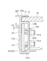
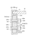
- FIG. 3 is a cross-sectional view taken along line AA in FIG. 2.
- FIG. 3 is a sectional view taken along line BB in FIG.
- FIG. 3 is the perspective view which showed the module frame of the connection part of internal angle (theta) 4 in the solar cell module of FIG.
- FIG. 3 is the perspective view which showed the coupling member which has the same thickness in the solar cell module of FIG.
- FIG. 3 is a cross-sectional view taken along the line CC of FIG. FIG.
- FIG. 3 is a DD sectional view of FIG. 2. It is the perspective view which showed the module frame of the connection part of interior angle (theta) 5 in the solar cell module of FIG. It is the bottom view which showed the auxiliary
- FIG. 6 is a plan view illustrating an outline of a solar cell array according to a first modification of the first embodiment.
- FIG. 6 is a plan view showing an outline of a solar cell array according to a second modification of the first embodiment. It is a top view which shows as a state which looked at the outline of the solar cell module which concerns on Embodiment 2 of this invention, and a module frame in planar view.
- FIG. 6 is a plan view illustrating an outline of a solar cell array according to a first modification of the first embodiment.
- FIG. 6 is a plan view showing an outline of a solar cell array according to a second modification of the first embodiment.
- It is a top view which shows as a state which looked at the outline of the
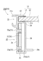
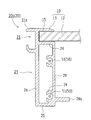
- FIG. 23B is an enlarged cross-sectional view showing an enlarged cross-sectional state of the joint member taken along arrows 1B-1B in FIG. 23A.
- FIG. 24 is an enlarged cross-sectional view showing an enlarged cross-sectional state of the joint member taken along arrows 1C-1C in FIG. 23A.
- FIG. 10 is a perspective view showing a joint member according to a first modification example of the fourth embodiment.
- FIG. 10 is a perspective view showing a joint member according to a second modification of the fourth embodiment.
- FIG. 10 is a perspective view showing a joint member according to a third modification of the fourth embodiment.
- FIG. 10 is a cross-sectional view showing a solar cell module according to a fourth modification example of the fourth embodiment. It is the top view which showed the outline of the solar cell module by Embodiment 5 of this invention, and a solar cell array provided with the same. It is the top view which showed the outline of the solar cell module by Embodiment 6 of this invention, and a solar cell array provided with the same.
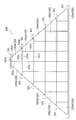
- the solar cell array 500 includes a plurality of solar cell modules 100 attached to a horizontal rail 501.
- This solar cell array 500 is formed in a substantially triangular shape when seen in a plan view, and is installed in a triangular or trapezoidal installation location such as a dormitory roof, for example.
- the horizontal rails 501 are formed so as to extend in the horizontal direction, and a plurality of the horizontal rails 501 are provided at predetermined intervals in the vertical direction (ridge building direction).
- the solar cell modules 100 are arranged in a matrix (matrix shape), the solar cell module 100a arranged at one end in the horizontal direction (row direction) of each stage, and the other end in the horizontal direction of each stage.
- the solar cell module 100b arrange
- the solar cell modules 100a and 100b are examples of the “second solar cell module” of the present invention, and the solar cell module 100c is an example of the “first solar cell module” of the present invention.
- the solar cell module 100a is formed in a pentagonal shape when seen in a plan view, and three corners are perpendicular and two corners are obtuse. Specifically, the solar cell module 100a connects the lower lateral side 101a, the upper lateral side 102a shorter than the lower lateral side 101a, and the lower lateral side 101a and the upper lateral side 102a. It includes an inner vertical side 103a, an outer vertical side 104a shorter than the inner vertical side 103a, and a hypotenuse 105a connecting the upper horizontal side 103a and the outer vertical side 104a. The outer vertical side 104a is shorter than the upper horizontal side 102a.
- a cross rail 501 is disposed below the lower lateral side 101a and the upper lateral side 102a.
- the solar cell module 100b is formed symmetrically with the solar cell module 100a. In addition, since the solar cell module 100b is configured in substantially the same manner as the solar cell module 100a, description of the solar cell module 100b is omitted.
- the solar cell module 100c is formed in a rectangular shape when seen in a plan view, and four corners are perpendicular. Specifically, the solar cell module 100c includes a lower lateral side 101c, an upper lateral side 102c, an inner vertical side 103c, and an outer vertical side 104c. In the solar cell module 100c, the cross rails 501 are respectively disposed below the lower lateral side 101c and the upper lateral side 102c. Further, the upper horizontal side 102c and the outer vertical side 104c have the same length as the inner vertical side 103a of the solar cell module 100a.
- восем ⁇ solar cell modules 100c are provided in the first stage (bottom stage), six are provided in the second stage, four are provided in the third stage, and 2 are provided in the fourth stage. It is provided individually and is not provided in the fifth stage (uppermost stage).
- the solar cell modules 100c correspond (continue) in the vertical direction (column direction) below the solar cell modules 100a and 100b except for the outermost solar cell modules 100a and 100b. Is arranged. That is, the vertical side 103a inside the solar cell module 100a and the vertical side 103c inside the solar cell module 100c arranged below the solar cell module 100a are arranged in a straight line in the vertical direction. By arranging in this way, it is possible to facilitate alignment work at the construction site of the solar cell array 500 and prevent erroneous work.
- the lower lateral side 101a of the solar cell module 100a is configured to be longer than the upper lateral side 102c of the solar cell module 100c.
- the length of the lower side 101a of the solar cell module 100a is smaller than the sum of the length of the upper side 102c of the solar cell module 100c and the length of the upper side 102a of the solar cell module 100a. It is comprised so that it may become.
- the lower lateral side 101a of the predetermined solar cell module 100a includes the entire length of the upper lateral side 102c of the lower one-stage solar cell module 100c and the upper lateral side of the lower-stage solar cell module 100a. A part of 102a is adjacently arranged.
- the predetermined solar cell module 100a overlaps with the lower one-stage solar cell module 100a in the vertical direction. That is, the predetermined solar cell module 100a is configured such that the outer vertical side 104a protrudes more outward than the outer vertical side 104c of the solar cell module 100c one step below. Moreover, the hypotenuse 105a of the solar cell module 100a at each stage is arranged on one inclined straight line.
- the predetermined solar cell module 100a is, for example, a solar cell module 100a other than the lowermost solar cell module 100a (solar cell module 100a located in the second to fifth stages).
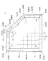
- the solar cell module 100a includes a solar cell module body 10, module frame bodies 121 to 125 that support the solar cell module body 10, and auxiliary frame bodies 126 that reinforce the module frame bodies 121 to 125 ( 20), a joint member 131 for connecting the module frame bodies 123 and 124, and a joint member 132 for connecting the module frame bodies 124 and 125.
- the solar cell module body 10 is formed in a pentagonal shape when seen in a plan view, and includes a cell region 12 having a plurality of solar cells 11 and an outer peripheral region 13 disposed on the outer periphery of the cell region 12.
- the solar cells 11 are arranged in a matrix (matrix) as viewed in a plan view.
- the solar cells 11 are disposed between the back-side protective member and the front-side translucent substrate, and a sealing member for sealing the solar cells 11 is filled.
- the solar battery cell 11 is a silicon-based solar battery (for example, crystalline or amorphous), a compound-based solar battery (for example, GaAs-based or CIS-based), or an organic-based solar battery (for example, dye-sensitized type). Any of these may be used.
- the module frame bodies 121 to 125 are arranged on each side of the solar cell module body 10 and formed so as to extend along each side. Specifically, the module frame bodies 121 and 123 are arranged in parallel, and the module frame body 121 is longer than the module frame body 123. The module frame bodies 122 and 125 are arranged in parallel, and the module frame body 122 is longer than the module frame body 125. The module frame bodies 122 and 125 are disposed so as to be orthogonal to the module frame body 121, and the module frame body 124 is disposed so as to intersect with the module frame bodies 123 and 125.
- the module frame 121 is disposed on the lower lateral side 101a (see FIG. 1), and the module frame 123 is disposed on the upper lateral side 102a (see FIG. 1).
- the module frame 122 is disposed on the inner vertical side 103a (see FIG. 1), and the module frame 125 is disposed on the outer vertical side 104a (see FIG. 1).
- the module frame 124 is disposed on the hypotenuse 105a (see FIG. 1).
- the module frames 121 to 125 are made of, for example, aluminum or an aluminum alloy, and have the same cross-sectional shape by being formed by extrusion molding. Specifically, as shown in FIG. 3, the module frame 121 includes a fitting portion 121a into which the outer peripheral region 13 (see FIG. 2) of the solar cell module body 10 is fitted, and a lower portion of the fitting portion 121a. It includes a hollow support portion 121b and an outer surface 121c. The module frame 121 is formed to extend in a direction perpendicular to the paper surface of FIG.
- the fitting part 121a is formed in a groove shape with open sides, and is configured to sandwich the front and back surfaces of the solar cell module body 10.
- the buffer member 15 (refer FIG. 11) is arrange
- the support part 121b is formed in a rectangular shape, and is configured to support the outer peripheral region 13 of the solar cell module body 10.
- the support part 121b includes an inner side surface 121d and a threaded part 121e formed inside. Two female thread portions 121e are provided at a predetermined interval in the vertical direction, and are formed so as to protrude from the inner side surface 121d to the outer side surface 121c side.
- the cross-sectional shape of the module frame 123 is the same as that of the module frame 121 as shown in FIG.
- the module frame 122 includes a fitting portion 122a into which the outer peripheral region 13 of the solar cell module body 10 is fitted, and a hollow support portion disposed below the fitting portion 122a. 122b and an outer surface 122c.
- the module frame 122 is formed to extend in a direction perpendicular to the paper surface of FIG.
- the fitting portion 122a is formed in a groove shape with open sides, and is configured to sandwich the front and back surfaces of the solar cell module body 10.
- the buffer member 15 (refer FIG. 11) is arrange
- the support part 122b is formed in a rectangular shape, and is configured to support the outer peripheral region 13 of the solar cell module body 10.
- the support portion 122b has an inner side surface 122d.
- the cross-sectional shapes of the module frames 124 and 125 are the same as those of the module frame 122 as shown in FIG.
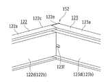
- the module frame bodies 121 to 125 are connected at each corner. Specifically, in the solar cell module 100a, as shown in FIG. 2, the adjacent module frame bodies 121 and 122 are connected at the connecting portion 151 at the inner angle ⁇ 1, and the adjacent module frame bodies 122 and 123 are connected at the connecting portion 152. The adjacent module frame bodies 123 and 124 are connected at the connecting portion 153 at the inner angle ⁇ 3, and the adjacent module frame bodies 124 and 125 are connected at the connecting portion 154 at the inner angle ⁇ 4. And 121 are connected to each other at the connecting portion 155 at an internal angle ⁇ 5.
- the internal angles ⁇ 1, ⁇ 2, and ⁇ 5 are 90 degrees, and the internal angles ⁇ 3 and ⁇ 4 are larger than 90 degrees.
- the crosspieces 151, 152, 153, and 155 have a horizontal beam 501 (see FIG. 1) disposed below, whereas the connection unit 154 has no horizontal beam 501 disposed below. Therefore, the connecting portions 151, 152, 153, and 155 are fixed to the horizontal rail 501, but the connecting portion 154 is in a floating state without being fixed to the horizontal rail 501.
- a contact surface 122e is formed at one end of the module frame 122, and one end of the module frame 121 abuts against the contact surface 122e. ing.
- the contact surface 122e is formed so as to extend from the outer surface 122c, and is configured to close the end surface of one end portion of the module frame 121.
- the length of the contact surface 122e is substantially the same as the width of the module frame 121.
- the contact surface 122e is formed with two screw insertion holes (not shown) at a predetermined interval in the vertical direction, and the screws 61 (see FIG. 2) are connected to the module frame through the screw insertion holes.
- the module frame bodies 121 and 122 are connected by being attached to the female thread portion 121e (see FIG. 3) of the body 121.
- an opening 121f for discharging moisture is formed on the inner side surface 121d of the module frame 121.
- the opening 121f is formed in a track shape (rounded rectangular shape) and is formed so as to straddle the inner side surface 122d of the module frame 122. For this reason, the opening part 121f has a function of communicating the inside of the support part 121b and the inside of the support part 122b while communicating the inside of the support part 121b to the outside air.
- the opening 121f is formed by cutting (drilling), for example, because the female screw 121e is formed on the support 121b.
- the connecting portion 152 has a contact surface 122e formed at the other end of the module frame 122, and one end of the module frame 123 abuts against the contact surface 122e. ing.
- the contact surface 122e is formed so as to extend from the outer surface 122c, and is configured to close the end surface of one end portion of the module frame 123.
- the length of the contact surface 122e is substantially the same as the width of the module frame 123.
- the contact surface 122e is formed with two screw insertion holes (not shown) at predetermined intervals in the vertical direction, and the screws 62 (see FIG. 2) are connected to the module frame through the screw insertion holes.
- the module frame bodies 122 and 123 are connected by being attached to the female thread portion 123e (see FIG. 3) of the body 123.
- an opening 123f for discharging moisture is formed on the inner side surface 123d of the module frame 123.
- the opening 123f is formed in a track shape (rounded rectangular shape) and is formed so as to straddle the inner side surface 122d of the module frame 122. For this reason, the opening portion 123f has a function of communicating the inside of the support portion 123b with the outside air and communicating the inside of the support portion 123b and the inside of the support portion 122b.
- the opening 123f is formed by cutting, for example, because the female threaded portion 123e is formed in the support portion 123b.
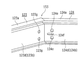
- connection 153 In the connecting portion 153, as shown in FIG. 2, since the inner angle ⁇ 3 is larger than 90 degrees, the other end of the module frame 123 and one end of the module frame 124 are connected using the joint member 131. ing. Here, the end surface of the other end portion of the module frame 123 and the end surface of the one end portion of the module frame 124 are formed so as to be inclined when seen in a plan view, and the inclined end surfaces are abutted with each other. .
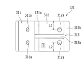
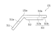
- the joint member 131 is made of, for example, aluminum or an aluminum alloy, and is formed in a plate shape having a bent portion 131a as shown in FIGS.
- the joint member 131 has a bent portion 131 a disposed at the boundary between the module frame bodies 123 and 124 and is disposed so as to straddle the boundary between the module frame bodies 123 and 124. Note that the angle of the bent portion 131a is the same as the inner angle ⁇ 3.
- the joint member 131 includes a first plate portion 311 disposed inside the support portion 123b of the module frame 123, a second plate portion 312 disposed inside the support portion 124b of the module frame 124, and a support. And a communication part 313 that communicates the parts 123b and 124b.
- the 1st board part 311 and the 2nd board part 312 have different thickness, and are formed so that it may continue through the bending part 131a.
- the thickness of the first plate portion 311 is smaller than that of the second plate portion 312.
- the 1st board part 311 is inserted in the support part 123b of the module frame 123 in the state which avoided the internal thread part 123e.
- the first plate portion 311 is disposed between the outer surface 123c of the module frame 123 and the female screw portion 123e.
- a space communicating with the support portion 124b is formed between the first plate portion 311 and the inner side surface 123d.
- the height of the first plate portion 311 is formed to be slightly smaller than the distance between the lower end surface and the upper end surface of the support portion 123b.
- the first plate portion 311 has two bolt insertion holes 311a formed at a predetermined interval in the vertical direction.
- a bolt insertion hole 123g (see FIG. 7) is formed on the outer surface 123c and the inner side surface 123d of the support portion 123b of the module frame 123 so as to correspond to the bolt insertion hole 311a.
- the bolt insertion hole 123g on the inner side surface 123d has a female thread portion 123e formed on the inner side surface 123d. Therefore, the bolt insertion hole 123g on the outer side surface 123c is formed by, for example, punching ( Formed by pressing).
- the thickness of the second plate portion 312 is larger than that of the first plate portion 311. As shown in FIG. 12, the second plate portion 312 is formed such that the thickness is slightly smaller than the distance between the outer surface 124c and the inner surface 124d, and the height is the lower end surface and the upper end surface of the support portion 124b. It is formed to be slightly smaller than the distance between. That is, the second plate portion 312 is formed so as to substantially block the support portion 124b except for the communication portion 313 when inserted into the support portion 124b.
- the second plate portion 312 has two bolt insertion holes 312a formed at predetermined intervals in the vertical direction.
- bolt insertion holes 124e are formed on the outer surface 124c and the inner side surface 124d of the support portion 124b of the module frame 124 so as to correspond to the bolt insertion holes 312a.
- an opening 124f for discharging moisture is formed between the bolt insertion holes 124e on the inner side surface 124d of the support portion 124b.
- the bolt insertion hole 124e and the opening 124f are formed by punching, for example.
- the communication portion 313 is formed in the second plate portion 312 and includes a groove portion 313a disposed between the bolt insertion holes 312a, an end portion of the groove portion 313a, and the like.
- a first concave portion 313b that communicates with the first concave portion 313b.
- the groove-shaped portion 313a is formed so as to extend in the lateral direction (the direction orthogonal to the thickness direction and the height direction of the joint member 131), and a space between the first plate portion 311 and the inner side surface 123d, 1 has a function of communicating with the concave portion 313b.
- the first concave portion 313b is formed at the end of the second plate portion 312 opposite to the bent portion 131a so as to extend in the vertical direction (height direction).
- the support portions 123b and 124b are communicated by the communicating portion 313, and the opening portion 124f is disposed at a position corresponding to the groove-like portion 313a.
- the fact that the opening 124f is disposed at a position corresponding to the groove 313a indicates that at least a part of the opening 124f is at a position overlapping the groove 313a.
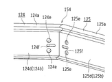
- the inner angle ⁇ 4 is larger than 90 degrees, so that the other end of the module frame 124 and the one end of the module frame 125 are connected using the joint member 132.
- the end surface of the other end portion of the module frame body 124 and the end surface of the one end portion of the module frame body 125 are formed so as to be inclined when seen in a plan view, and the inclined end surfaces are abutted against each other. .
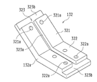
- the joint member 132 is made of, for example, aluminum or an aluminum alloy, and is formed in a plate shape having a bent portion 132a as shown in FIGS.
- the joint member 132 has a bent portion 132 a disposed at the boundary between the module frame bodies 124 and 125 and is disposed so as to straddle the boundary between the module frame bodies 124 and 125.
- the angle of the bent portion 132a is the same as the inner angle ⁇ 4.
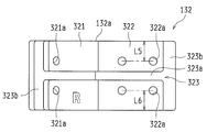
- the joint member 132 includes a first plate portion 321 disposed inside the support portion 124b of the module frame body 124, a second plate portion 322 disposed inside the support portion 125b of the module frame body 125, and a support.
- the communication part 323 which connects the parts 124b and 125b is included.
- the 1st board part 321 and the 2nd board part 322 have the same thickness, and are formed so that it may continue via the bending part 132a.
- the first plate portion 321 is formed so that the thickness is slightly smaller than the distance between the outer surface 124c and the inner surface 124d, and the height of the first plate portion 321 is lower than the lower end surface and the upper end surface of the support portion 124b. It is formed to be slightly smaller than the distance between them. That is, the first plate portion 321 is formed so as to substantially block the support portion 124b except for the communication portion 323 when inserted into the support portion 124b.
- the first plate portion 321 has two bolt insertion holes 321a formed at a predetermined interval in the vertical direction. Also, bolt insertion holes 124e are formed on the outer surface 124c and the inner side surface 124d of the support portion 124b of the module frame 124 so as to correspond to the bolt insertion holes 321a. Also, an opening 124f for discharging moisture is formed between the bolt insertion holes 124e on the inner side surface 124d of the support portion 124b.
- the bolt insertion hole 124e and the opening 124f are formed by punching, for example.
- the second plate portion 322 is formed so that the thickness is slightly smaller than the distance between the outer side surface 125c and the inner side surface 125d, and the height is between the lower end surface and the upper end surface of the support portion 125b. It is formed to be slightly smaller than the distance between them. That is, the second plate portion 322 is formed so as to substantially close the support portion 125b except for the portion of the communication portion 323 when inserted into the support portion 125b.
- the second plate portion 322 has two bolt insertion holes 322a formed at a predetermined interval in the vertical direction.
- bolt insertion holes 125e are formed in the outer surface 125c and the inner surface 125d of the support portion 125b of the module frame 125 so as to correspond to the bolt insertion holes 322a.
- an opening 125f for discharging moisture is formed between the bolt insertion holes 125e on the inner side surface 125d of the support portion 125b.
- the bolt insertion hole 125e and the opening 125f are formed by punching, for example.
- the communication portion 323 is disposed between the bolt insertion holes 321a, a groove-shaped portion 323a disposed between the bolt insertion holes 322a, and both end portions of the groove-shaped portion 323a. And a pair of first concave portions 323b communicating with each other.
- the groove-shaped portion 323a is formed so as to extend in the lateral direction (the direction orthogonal to the thickness direction and the height direction of the joint member 132), and has a function of communicating the pair of first concave portions 323b.
- the first concave portion 323b is formed at the end of the first plate portion 321 and the second plate portion 322 opposite to the bent portion 132a so as to extend in the vertical direction (height direction).
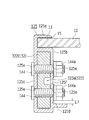
- the module frame 124 and the joint member 132 can be obtained by attaching the nut 143 a to the bolt 143 with the bolt 143 inserted into the bolt insertion holes 321 a and 124 e. Is concluded. As shown in FIGS. 2, 13, and 18, when the bolt 144 is inserted into the bolt insertion holes 322 a and 125 e, the nut 144 a is attached to the bolt 144, whereby the module frame 125 and the joint member 132 are attached. Is concluded. Thereby, in the connection part 154, the module frame bodies 124 and 125 are connected using the joint member 132.
- the support portions 124b and 125b are communicated with each other by the communication portion 323, and the openings 124f and 125f are disposed at positions corresponding to the groove-shaped portions 323a.
- the fact that the openings 124f and 125f are arranged at positions corresponding to the groove-like portions 323a means that at least a part of the openings 124f and 125f is at a position overlapping the groove-like portions 323a. .
- a contact surface 125g is formed at the other end of the module frame 125, and the other end of the module frame 121 abuts against the contact surface 125g. ing.
- the contact surface 125g is formed so as to extend from the outer surface 125c, and is configured to block the end surface of the other end portion of the module frame 121.
- the length of the contact surface 125g is substantially the same as the width of the module frame 121.
- two screw insertion holes (not shown) are formed in the contact surface 125g at a predetermined interval in the vertical direction, and the screws 63 (see FIG. 2) are connected to the module frame via the screw insertion holes.
- the module frame bodies 125 and 121 are connected by being attached to the female thread portion 121e (see FIG. 3) of the body 121.
- an opening 121f for discharging moisture is formed on the inner side surface 121d of the module frame 121.
- the opening 121f is formed in a track shape (rounded rectangular shape) and is formed so as to straddle the inner side surface 125d of the module frame 125. For this reason, the opening part 121f has a function of communicating the inside of the support part 121b and the inside of the support part 125b while communicating the inside of the support part 121b to the outside air.
- the opening 121f is formed by cutting, for example, because the female screw 121e is formed in the support 121b.
- joint members 131 and 132 used in the connecting portions 153 and 154 have a symmetrical shape when used in the solar cell module 100a shown in FIG. 1 and when used in the solar cell module 100b. However, they are not completely the same structure.
- joint members 131 and 132 used in solar cell module 100a are joint members 131a and 132a
- joint members 131 and 132 used in solar cell module 100b are joint members 131b and 132b.
- the joint members 131a and 131b differ in the distance L1 from the end surface to one bolt insertion hole 312a and the distance L2 to the other bolt insertion hole 312a (see FIG. 9).
- the distance L1 and the distance L2 are the same length, the joint member 131a and the joint member 131b have the same structure, but since the distances are different, the structure is not the same.
- the reason why the distance L1 and the distance L2 are different is as follows.
- a shift in the rotational direction is likely to occur between the joint member and the frame. That is, the joining of the frame body is easy to loosen.
- the displacement in the rotational direction is less likely to occur than in the case of one.
- the rotational force can be further suppressed by increasing the distance between the two bolt insertion holes.
- the distance L5 to the end face and one bolt insertion hole 322a is different from the distance L6 to the other bolt insertion hole 322a (see FIG. 15).
- This basic idea is the same as the relationship between the joint member 131a and the joint member 131b.
- the distance L5 and the distance L6 can be the same length. Designed to have different lengths. This is to reduce the manufacturing cost by making the processing part of the press machine that opens the bolt insertion hole in common.
- the difference between the distance L1 and the distance L2 is a level that is difficult to distinguish visually (difference of about 1 mm), and the joint member 131a and the joint member 131b are likely to be misunderstood. Similarly, the joint member 132a and the joint member 132b are likely to be misunderstood. In addition, if they are mistaken, they may be forcibly bolted. If the joint member is mistakenly stopped, an excessive load is applied to the frame body, which may cause damage.
- the joint member 131a and the joint member 131b In order to eliminate such a mistake in the joint members, it is desirable to attach different identification marks to the joint member 131a and the joint member 131b. Similarly, it is desirable to attach different identification marks to the joint member 132a and the joint member 132b.
- the joint member 131 a and 132 a used in the solar cell module 100 a that is the right corner module may be marked with an R mark.
- the joint member 131b and 132b used in the solar cell module 100b that is the left corner module may be marked with an L mark. This eliminates the mistake of the joint members attached to the respective corner modules during the frame assembly operation.
- the joint members 131 and 132 are usually created by die casting.
- a joint member with an identification mark can be created by pre-molding.
- transformation by press is also considered.
- both the joint member 131a and the joint member 132a have distinctly different shapes, there is a low possibility that the attachment location is wrong (if the mistake is made, the joint member does not fit into the frame), as described above.
- Both can be the same R mark.
- both the joint member 131b and the joint member 132b can have the same L mark.
- different identification marks may be attached to all of the joint members 131a, 132a, 131b, and 132b. Thereby, the possibility that the attachment location of the joint member is mistaken becomes lower.
- the auxiliary frame body 126 is hung between the module frame bodies 121 and 124.
- the auxiliary frame 126 is made of, for example, aluminum or an aluminum alloy, and is disposed below the solar cell module body 10 and in parallel with the module frames 122 and 125.
- the auxiliary frame 126 has one end connected to the module frame 121 and the other end connected to the module frame 124.
- the module frame body 124 and the auxiliary frame body 126 are connected in the vicinity of the center portion in the length direction of the module frame body 124.
- FIG. 20 is a figure for demonstrating the auxiliary
- the solar cell module 100a disposed at the end in the horizontal direction of each stage is formed in a pentagon, and the three corners of the solar cell module 100a are perpendicular. Since the two corners are obtuse, since the solar cell module 100a does not have an acute corner, it is possible to prevent the worker from being injured during the installation work, and thus improve safety. Can be achieved.
- the lower lateral side 101a of the solar cell module 100a may be made longer than the upper lateral side 102c of the solar cell module 100c. it can.
- the light receiving area can be improved. Even if the lower side 101a of the solar cell module 100a is longer than the upper side 102c of the solar cell module 100c, the connecting portion 155 of the solar cell module 100a can be fixed to the horizontal beam 501.
- the solar cell array 600 may include the dummy piece 601 as in the first modification shown in FIG.
- the dummy piece 601 is formed in a triangular shape when seen in a plan view, and is disposed adjacent to a predetermined solar cell module 100a and the lower one solar cell module 100a.
- the dummy piece 601 is arranged outside the vertical side 104a outside the predetermined solar cell module 100a, and is arranged above the horizontal side 102a above the one-stage lower solar cell module 100a.
- the slant side 105a of the predetermined solar cell module 100a and the slant side 105a of the solar cell module 100a one step below are formed.
- the outer side (outer edge) of the solar cell array 600 can be formed into an oblique straight line, so that the appearance can be improved.
- the dummy piece 601 is an example of the “decorative member” in the present invention.
- the present invention is not limited thereto, and the solar cell is not limited to the solar cell module 100
- the solar cell modules 100a and 100b may not be provided on the lower side of the array 700. That is, you may make it comprise only the rectangular solar cell modules 100c and 100d in the lower stage side where intensity
- rectangular solar cell modules 100d having a lateral length larger than that of the solar cell module 100c are arranged at both ends of the first and second stages.
- the solar cell module 100d is an example of the “first solar cell module” in the present invention.
- Embodiment 1 an example in which the solar cell array 500 has five stages has been described.
- the present invention is not limited to this, and the solar cell array may have any number of stages.
- the present invention is not limited thereto, and the rectangular shape is provided in the uppermost stage of the solar cell array.
- a solar cell module may be provided.
- the openings 121f, 123f, 124f, and 125f for discharging moisture may not be formed.
- the communication member 313 (323) may not be formed in the joint member 131 (132).
- the bolt insertion hole 123g may be formed only on the outer surface 123c of the support portion 123b, and the module frame 123 and the joint member 131 may be screwed from the outer surface 123c side.
- the module frames 124 and 125 may be screwed from the outer surface 123c side.
- a screw thread is formed in the bolt insertion holes 321a and 124e (322a and 125e) into which the bolt 143 (144) is inserted, and the bolt 143 (144) and the bolt insertion hole 321a are formed.
- 124e (322a and 125e) may be screwed together.
- the bolt insertion holes 321a and 124e (322a and 125e) are not threaded, and the bolt 143 (144) and the bolt insertion holes 321a and 124e (322a and 125e) may not be screwed together.
- FIG. 23A is a plan view showing an outline of solar cell module 1 and module frame 20 according to Embodiment 2 of the present invention as seen in a plan view.
- a solar cell module 1 according to Embodiment 2 includes a solar cell module body 10 including a cell region 12 in which solar cells 11 are disposed and an outer peripheral region 13 disposed on the outer periphery of the cell region 12, and a solar cell module body.
- a plurality of module frame bodies 20 in this embodiment, the first module frame body 20a, the second module frame body 20b, the third module frame body 20c, the fourth module frame body 20d, 5 of the fifth module frame 20e).
- the module frame 20 may be simply used.
- the solar cell module main body 10 can secure positioning accuracy and mechanical strength because the outer peripheral region 13 is supported and protected by the module frame 20.
- the solar cell module body 10 is laminated with a translucent substrate disposed on the light receiving surface side, a solar cell 11, a sealing portion that seals the solar cell 11, and a back surface protection member that protects the back surface.
- a glass substrate is used as the translucent substrate
- EVA ethylene vinyl acetate
- PET PET
- PET Polyethylene terephthalate
- the module frame 20 is also pentagonal according to the solar cell module body 10. That is, the module frame 20 is obtained by combining the first module frame 20a, the second module frame 20b, the third module frame 20c, the fourth module frame 20d, and the fifth module frame 20e with each other (mutually It is a pentagon).
- the reason why the shape of the solar cell module 1 in a plan view is a pentagon is to match the situation of the installation location (for example, the rooftop or roof of a building). That is, the planar shape of the solar cell module 1 can be changed from a general rectangle to, for example, a triangle, a pentagon, and the like.
- the module frame 20 according to the second embodiment is applied to the solar cell module 1 having a polygon other than a rectangle. By making the polygon according to the situation of the installation location, the installation location can be effectively utilized to maximize the generated power.
- the solar cell module body 10 is preferably a pentagon or more polygon in plan view. Therefore, the solar cell module 1 can be applied to the solar cell module body 10 having a polygonal shape exceeding a quadrangle, and the reliability of the connecting portion 40 can be ensured.
- the module frame 20 is formed by extrusion processing (extrusion molding). Therefore, it is set as the state which has the same cross section in the length direction (namely, direction of each edge
- the module frame 20 is preferably made of aluminum or an aluminum alloy.
- the material to be used is appropriately selected in consideration of the balance between strength and lightness.
- the first module frame body 20a and the second module frame body 20b are connected to each other at an internal angle ⁇ 1 (for example, 90 degrees) via the connecting portion 41, and the second module frame body 20b and the third module frame body are connected.
- 20c is connected at an inner angle ⁇ 2 (for example, 90 degrees) through the connecting portion 42, and the third module frame body 20c and the fourth module frame body 20d are at an inner angle ⁇ 3 (for example, 130.8 degrees) through the connecting portion 43.
- the fourth module frame body 20d and the fifth module frame body 20e are connected at an internal angle ⁇ 4 (for example, 139.2 degrees) via the connection portion 44, and the fifth module frame body 20e and the first module frame body 20a are Are connected at an internal angle ⁇ 5 (for example, 90 degrees) through the connecting portion 45.
- ⁇ 4 for example, 139.2 degrees
- ⁇ 5 for example, 90 degrees
- the solar cell module body 10 has a pentagonal shape, and three positions of the inner angle ⁇ 1, the inner angle ⁇ 2, and the inner angle ⁇ 5 are right angles, and the two positions of the inner angle ⁇ 3 and the inner angle ⁇ 4 are different from 90 degrees.
- connecting portion 41, the connecting portion 42, the connecting portion 43, the connecting portion 44, and the connecting portion 45 may be simply referred to as the connecting portion 40 when it is not necessary to distinguish them from each other.
- the first module frame body 20a and the second module frame body 20b are fastened (connected) by the fastening member 51, and in the connecting portion 42, the second module frame body 20b and the third module frame body 20c.
- the fastening member 52 is fastened (coupled) by the fastening member 52
- the third module frame body 20 c and the fourth module frame body 20 d are fastened (coupled) by the fastening member 33 a and the fastening member 33 b via the joint member 31 in the joint portion 43.
- the fourth module frame body 20d and the fifth module frame body 20e are fastened (connected) by the fastening member 33c and the fastening member 33d via the joint member 32.
- the fifth module The frame body 20e and the first module frame body 20a are fastened (connected) by a fastening member 53.
- the joint member 31 and the joint member 32 may be simply referred to as the joint member 30 when it is not necessary to distinguish between them. Further, when there is no need to distinguish the fastening member 33a, the fastening member 33b, the fastening member 33c, and the fastening member 33d from each other, the fastening member 33 may be simply used. Moreover, when it is not necessary to distinguish the fastening member 51, the fastening member 52, and the fastening member 53 from each other, the fastening member 50 may be simply used.
- the connecting portion 41, the connecting portion 42, and the connecting portion 45 can specifically adopt the following connecting structure.
- the first wall portion 26 (see FIG. 25) of the second module frame body 20b protrudes from the second module frame body 20b and comes into contact with the end surface of the first module frame body 20a. Since the screws are formed on the second wall portion 28 (see FIG. 25) of the first module frame 20a, they are fitted into the screw portions 29 (see FIG. 25) and screwed. By adopting the screwing structure, it is possible to easily disassemble and reuse the component parts.
- the first wall portion 26 is also an outer wall because the position relative to the second wall portion 28 is on the outside, and the second wall portion 28 is positioned on the inner side relative to the first wall portion 26. It is also an inner wall. That is, since the second wall portion 28 is integrally connected to the upper end portion 24, the lower end portion 25, and the first wall portion 26, the support portion 23 forms a rectangular hollow structure.
- connection part 41 since the end surface of the 1st module frame 20a in the connection part 41 is orthogonally formed with respect to the length direction of the 1st module frame 20a, fastening at a right angle is made with high precision. . Moreover, the 1st wall part 26 of the 2nd module frame 20b is made into a highly accurate plane.
- the first wall portion 26 (see FIG. 25) of the second module frame body 20b protrudes from the second module frame body 20b and comes into contact with the end surface of the third module frame body 20c. Since the screws are formed on the second wall portion 28 (see FIG. 25) of the third module frame 20c, they are fitted into the screw portions 29 (see FIG. 25) and screwed.
- the fastening at a right angle is made with high precision.
- the 1st wall part 26 of the 2nd module frame 20b is made into a highly accurate plane.
- the first wall portion 26 (see FIG. 23B) of the fifth module frame body 20e protrudes from the fifth module frame body 20e and comes into contact with the end surface of the first module frame body 20a. Since the screws are formed on the second wall portion 28 (see FIG. 25) of the first module frame 20a, they are fitted into the screw portions 29 (see FIG. 25) and screwed.
- the end surface of the 1st module frame 20a in the connection part 45 is formed orthogonally with respect to the length direction of the 1st module frame 20a, fastening at a right angle is made with high precision. . Further, the first wall portion 26 of the fifth module frame 20e is a highly accurate plane.
- connection structure different from the connection part 42 and the connection part 45 is adopted. Specifically, it is as follows.
- the end surface of the third module frame body 20c and the end surface of the fourth module frame body 20d are formed so as to form an internal angle ⁇ 3 (for example, 130.8 degrees different from 90 degrees) and are abutted against each other. They are connected by a joint member 31. Therefore, the joint member 31 (joint member 30) is formed of a single plate material.
- the fastening member 52 is applied to the third module frame 20c at the connecting portion 42. Therefore, the third module frame 20c has the screw portion 29 because the fastening member 52 is screwed. Moreover, since the internal thread part 29 is formed over the full length of the 3rd module frame 20c, the end surface of the 3rd module frame 20c in the connection part 43 will be in the state which has the internal thread part 29. (See FIG. 23C).
- the inner angle ⁇ 3 formed by the connecting portion 43 and the inner angle ⁇ 4 formed by the connecting portion 44 on the opposite side of the connecting portion 43 are different from the right angle. Accordingly, in the fourth module frame 20d, the female screw portion 29 applied by the connecting portion 40 whose inner angle is a right angle is not necessary, and there is no need to have the female screw portion 29. Therefore, the fourth module at the connecting portion 43 is not required.
- the end surface of the frame body 20d is in a state where the female thread portion 29 is not provided (see FIG. 23B).
- the joint member 31 is inserted into the space formed between the first wall portion 26 and the female screw portion 29 (see FIG. 23C), and the In the 4-module frame 20d, the joint member 31 is inserted into a space (see FIG. 23B) formed inside the first wall portion 26.
- a restricting portion 27a for restricting the position of the joint member 31 from the first wall portion 26 in order to accurately position the joint member 31 (see FIG. 23B).
- the restriction portion 27a (hereinafter, simply referred to as the restriction portion 27) is formed as a protrusion with respect to the lower end portion 25, for example, and is formed by extrusion processing. Therefore, the length direction of the module frame 20 It is formed to extend.
- the joint member 31 is disposed between the first wall portion 26 and the restricting portion 27a, so that the joint member 31 extends along the first wall portion 26. Since positioning can be performed with high accuracy, positioning with the same accuracy as that of the third module frame 20c side of the connecting portion 43 is possible.
- the fourth module frame body 20d is formed by extrusion, the state without the female thread portion 29 is formed over the entire fourth module frame body 20d, and the connection portion 44 has the same state. It is said.
- the joint member 31 is similarly extended and disposed on both the third module frame body 20c and the fourth module frame body 20d, and is similarly positioned.
- the joint member 31 is fastened to the third module frame 20c by the fastening member 33b and fastened to the fourth module frame 20d by the fastening member 33a.
- the flat joint member 31 bent at the internal angle ⁇ 3 is fastened to the third module frame 20c constituting the connecting portion 43 via the fastening member 33b, and the fourth module frame constituting the connecting portion 43. Fastened to 20d via a fastening member 33a. Therefore, since the strength of the joint member 31 acts effectively as it is, the connecting portion 43 secures the same strength as the joint member 31 and fastens the third module frame body 20c and the fourth module frame body 20d with high accuracy. (See FIGS. 23B and 23C).
- the end surface of the fourth module frame body 20d and the end surface of the fifth module frame body 20e are formed so as to form an internal angle ⁇ 4 (for example, 139.2 degrees different from 90 degrees) and are abutted against each other. They are connected by a joint member 32.
- connection part 45 since the 1st wall part 26 of the 5th module frame 20e protrudes from the 5th module frame 20e, and is connected with the internal thread part 29 which the 1st module frame 20a has, it is 5th.
- the module frame 20e does not need to have the female screw portion 29.
- the end surface of the fifth module frame 20e at the connecting portion 44 does not have the female thread portion 29 as in the end surface of the fourth module frame 20d at the connecting portion 44 (see FIG. 23B).
- the joint member 32 is inserted into the space defined between the first wall portion 26 and the restricting portion 27a in both the fourth module frame 20d and the fifth module frame 20e. That is, the joint member 32 is fastened to the fourth module frame 20d by the fastening member 33c, and fastened to the fifth module frame 20e by the fastening member 33d. That is, the fastening state at the connecting portion 44 is the same as the fastening state of the fastening member 33a applied at the connecting portion 43 (see FIG. 23B).
- the flat joint member 32 bent at the internal angle ⁇ 4 is fastened to the fourth module frame 20d constituting the connecting portion 44 via the fastening member 33c, and is attached to the fifth module frame 20e constituting the connecting portion 44. On the other hand, it is fastened via the fastening member 33d. Therefore, since the strength of the joint member 32 acts effectively, the connecting portion 44 ensures the same strength as the joint member 32 and fastens the fourth module frame body 20d and the fifth module frame body 20e with high accuracy. (See FIG. 23B).
- FIG. 23B is an enlarged cross-sectional view showing an enlarged cross-sectional state of the joint member 31 taken along the arrow 1B-1B in FIG. 23A.
- FIG. 23B shows a connected state at the connecting portion 43 (connecting portion 40) of the fourth module frame 20d (module frame 20).
- the connection state in the connection part 44 of the 4th module frame 20d and the connection state in the connection part 44 of the 5th module frame 20e are also the same.
- the module frame 20 is a module that holds a solar cell module body 10 that includes a cell region 12 in which the solar cells 11 are arranged and an outer peripheral region 13 that is arranged in the outer periphery of the cell region 12. This is the frame 20 (fourth module frame 20d).
- the module frame 20 includes a fitting portion 21 into which the outer peripheral region 13 is fitted, and a support portion 23 that supports the fitting portion 21, and the support portion 23 includes an upper end portion 24 that is coupled to the bottom portion 21 b of the fitting portion 21.
- a lower end 25 that is arranged away from the upper end 24 in a direction crossing the solar cell module main body 10 (a direction crossing the plane of the solar cell module main body 10) and faces the upper end 24, and the upper end 24 and the lower end
- a first wall portion 26 that is connected to the portion 25 and disposed along the outer peripheral region 13, and is disposed between the upper end portion 24 and the lower end portion 25 along the first wall portion 26 and extends to be adjacent to the other portion.
- a joint member 31 (joint member 30) inserted into the module frame body 20 (third module frame body 20c), and a restricting portion 27a (restricting portion 27) for restricting the position of the joint member 31 from the first wall portion 26; Be equipped That.
- the module frame body 20 (fourth module frame body 20d) includes a joint member 31 (joint member 30) and a regulation portion 27a (regulation portion 27) that regulates the position of the joint member 31 from the first wall portion 26. Since it comprises, it becomes possible to position easily and with high precision with respect to the other adjacent module frame 20, and to connect reliably.
- the fitting portion 21 and the support portion 23 are generally integrated. Further, the position of the restricting portion 27a from the first wall portion 26 is such that the joint member 31 is sandwiched between the restricting portion 27a and the first wall portion 26, and the joint member 31 is brought close to the first wall portion 26 by the restricting portion 27a. It is preferable that the position be in the state where it is in a state of being allowed to enter. More specifically, the coupling member 31 is brought into contact with the first wall portion 26 by the regulation (induction) of the regulation portion 27a and is slid and inserted between the first wall portion 26 and the regulation portion 27a. Preferably there is.
- the 1st wall part 26 is arrange
- region 13 the edge part of the solar cell module main body 10. In other words, the position which connects the outer end of the upper end part 24 and the lower end part 25).
- the distance between the first wall portion 26 and the second wall portion 28 is determined from the strength, balance, etc. as a support structure for the solar cell module body 10.
- the restricting portion 27a is disposed on the lower end 25 so as to face the upper end 24.
- the fourth module frame body 20d can be positioned in a self-aligned manner using the weight of the joint member 31, so that the interval from the first wall portion 26 can be easily determined.
- the module frame 20 can be easily connected. That is, workability, position accuracy, and strength can be ensured.
- the restricting portion 27a is preferably a protrusion.
- the fourth module frame body 20d can restrict the position of the joint member 31 with a simple configuration because the restricting portion 27a is formed by a protrusion.
- the protrusion (the restriction portion 27a) is extended along the length direction of the first wall portion 26.
- the fourth module frame body 20 d extends the protrusion along the extending direction of the first wall portion 26 (the direction along the outer periphery of the outer peripheral region 13), and thus the joint member 31 in the extending direction of the joint member 31. Since the position is restricted, more stable positioning can be achieved.
- the restricting portion 27a is arranged to extend in a continuous rail shape (projection) instead of a separated pin shape, a protrusion can be arranged corresponding to the entire length direction of the joint member 31. Therefore, positioning accuracy and mechanical strength are improved. As described above, since the module frame 20 is extrusion-molded, the protruding-line regulating portion 27a is easily and highly accurately formed.
- the restricting portion 27a may have a form in which, for example, a suitable number of rod pins are dispersed and arranged. Since the restricting portion 27a is disposed only in a necessary portion, the module frame body 20 can be reduced in weight.
- the support portion 23 is disposed on the cell region 12 side with respect to the first wall portion 26 and connects the upper end portion 24 and the lower end portion 25 to the outer peripheral region 13.
- positioned along is provided.
- the upper end 24, the lower end 25, the first wall 26, and the second wall 28 preferably form a hollow structure including the joint member 31 (joint member 30).
- the fourth module frame 20d (module frame 20) includes the joint member 30 by a hollow structure formed by the upper end 24, the lower end 25, the first wall 26, and the second wall 28. Therefore, damage to the joint member 30 can be prevented, and the reliability of the connection strength of the module frame 20 can be ensured.
- the shape of the joint member 30 to be inserted is a plate shape arranged in parallel with the first wall portion 26. Since it is possible to fasten the adjacent module frame 20 only by fastening the joint member 30 to the 1st wall part 26 by the fastening member 33, it is only necessary to adjust the cross-sectional shape (plate thickness) of the joint member 30. The strength of the joint member 30 can be ensured as necessary.
- the cross-sectional shape of the joint member 30 (a rectangular cross-sectional shape in a direction intersecting the length direction of the module frame 20; that is, a cross-section in the same direction as the arrows 1B-1B and 1C-1C in FIG. 23A)
- the long side (plate width, that is, the length in the vertical direction with respect to the solar cell module main body) is delimited by the interval between the upper end portion 24 and the lower end portion 25, and the short side (plate thickness) is An upper limit is defined in a range where the position is restricted.
- the length of the plate is a length along the first wall portion 26 in the length direction of the module frame represented in plan view.
- the range in which the position of the joint member 30 is restricted by the restriction portion 27 is, for example, the interval from the first wall portion 26 to the position where the protrusion of the restriction portion 27a rises in the case of the restriction portion 27a.
- the restricting portion 27e and the restricting portion 27f it is the distance from the first wall portion 26 that the bottom of the recess into which the joint member 30 is inserted has.
- the plate width of the joint member 30 can be sufficiently secured between the upper end portion 24 and the support portion 23.
- the plate thickness of the joint member 30 can be sufficiently ensured corresponding to the interval at which the restricting portion 27 acts on the joint member 30 from the first wall portion 26. Therefore, the joint member 30 can ensure sufficient strength in conformity with the shape of the module frame body 20 (inner shape of the first wall portion 26) in terms of plate thickness and plate width.
- the joint member 30 is formed of, for example, aluminum or an aluminum alloy, like the module frame 20. By applying the same material as that of the module frame 20, the strength can be ensured with high accuracy.
- the upper end part 24, the lower end part 25, the 1st wall part 26, and the 2nd wall part 28 form the rectangle as a rough shape.
- the strength of the module frame 20 can be further improved.
- the joint member 31 (joint member 30) is preferably fastened to the first wall portion 26.
- the fourth module frame body 20d (module frame body 20) fastens the joint member 31 (joint member 30) to the first wall portion 26, thereby improving the connection strength and improving the connection reliability.
- a fastening member 33a (fastening member 33) can be applied as a member for fastening the joint member 30 to the first wall portion 26.
- the fastening member 33a is, for example, a screw (male screw).
- the fastening member 33a is arrange
- fastening member 33a are disposed apart from both the upper end side (upper end portion 24 side) and the lower end side (lower end portion 25 side) of the joint member 31. Since it can oppose a rotational force by arrange
- the fastening member 33 may be one instead of two.
- the plate thickness of the joint member 30 is a hollow structure (first wall portion). 26 to the second wall portion 28.
- the distance from the first wall portion 26 without the second wall portion 28 to the tip of the upper end portion 24 and the lower end portion 25) is half to three. It is preferable to set it to about 1 / min. With this configuration, the joint member 30 can be prevented from being deformed with respect to the hollow structure, so that the strength of the module frame 20 can be maintained.
- the position of the restricting portion 27 is arranged between the tip of the upper end 24 or the tip of the lower end 25 opposite to the first wall 26 or the first wall 26 away from the second wall 28.
- the joint member 30 is disposed at a position where it does not contact the tip of the upper end 24, the tip of the lower end 25, or the second wall portion 28.
- a buffer member 15 made of, for example, an elastic body (rubber or resin) is disposed to suppress external impact on the solar cell module main body 10, and , Improve water tightness and environmental resistance.
- the module frame body 20 includes the flange portion 21s on the outer periphery of the fitting portion 21, it is possible to suppress the deformation of the first wall portion 26 to ensure strength and ensure an appropriate external shape. Moreover, since the module frame 20 includes the reinforcing portion 28s near the lower end portion 25 of the second wall portion 28, the deformation of the second wall portion 28 can be suppressed and the strength can be ensured.
- FIG. 23C is an enlarged cross-sectional view showing an enlarged cross-sectional state of the joint member 31 taken along the arrow 1C-1C in FIG. 23A.
- FIG. 23C shows a connection state of the third module frame body 20c (module frame body 20) at the connection section 43 (connection section 40). Since the basic configuration is the same as the configuration described in FIGS. 23A and 23B, different items will be mainly described.
- the support portion 23 is disposed on the cell region 12 side with respect to the first wall portion 26 and connects the upper end portion 24 and the lower end portion 25 to the outer peripheral region 13.
- 2nd wall part 28 arranged along the 2nd wall part 28, and the 2nd wall part 28 is arranged on the field opposite to the 1st wall part 26, and is adjacent to other module frame 20 (2nd module frame 20b).
- the first wall portion 26 is provided with a female screw portion 29 to be screwed, and the restricting portion 27 b (hereinafter simply referred to as the restricting portion 27) is constituted by the female screw portion 29.
- the module frame body 20 (third module frame body 20c) has a female screw portion 29 (female screw) to which another adjacent module frame body 20 (first wall portion 26 of the second module frame body 20b) is screwed. Since the tip of the portion 29 on the first wall portion 26 side functions as the restricting portion 27b, it is not necessary to form the restricting portion 27 separately, and productivity (workability) and versatility are improved.
- a pre-formed female thread portion 29 is applied as the restricting portion 27b, instead of newly forming the restricting portion 27. That is, the apex on the first wall portion 26 side of the female screw portion 29 formed on the second wall portion 28 and projecting toward the first wall portion 26 (the first female screw portion 29 is the first on the basis of the second wall portion 28. A vertex formed by a position close to the wall portion 26) functions as a restricting portion 27b for the joint member 31.
- the joint member 31 can be positioned with higher accuracy. Moreover, since the fastening member 50 is fastened by the end surface (for example, the end surface of the 3rd module frame 20c in the connection part 42), the internal thread part 29 is formed so that it may have high mechanical strength. The joint member 31 can be reliably positioned.
- the joint member 31 is fastened to the first wall portion 26 by the fastening member 33b.
- the fastening member fastening member 33b is, for example, a screw (male screw).
- the fastening member 33c and the fastening member 33d are configured similarly.
- the upper limit of the plate thickness of the joint member 31 is defined by the distance between the first wall portion 26 and the female thread portion 29. That is, the joint member 30 is formed of a plate that is thinner than the distance between the first wall portion 26 and the female screw portion 29.
- the other module frame body 20 (fourth module frame body 20d) at the connecting portion 43 does not have the female screw portion 29. Therefore, when the space is a simple space, the other module frame body 20 is fastened to the third module frame body 20c and extended.
- the restricting portion 27 that restricts the position of the joint member 31 is formed. Therefore, the joint member 31 can be easily and highly positioned along the first wall portion 26. Since the joint member 31 is brought into contact with the first wall portion 26 of the fourth module frame 20d by the fastening portion 33a, the mechanical strength can be ensured.
- a plurality of module frame bodies 20 for example, the first module frame body 20a, the second module frame body 20b, the third module frame body 20c, and the fourth module frame.
- the body 20d and the fifth module frame 20e for example, a combination of the third module frame 20c and the fourth module frame 20d, or the fourth module frame 20d and the fifth module frame 20e.
- the assembly is a module frame 20 according to the second embodiment, and is a connection portion 40 (for example, a connection in which a third module frame 20c and a fourth module frame 20d are connected to each other).
- Angle .theta.3, interior angle ⁇ 4 at the connecting portion 44) are different angle and 90 degrees.
- the solar cell module 1 according to the second embodiment has the module frame according to the second embodiment when the inner angle in plan view of the connecting portions 40 formed by being connected to each other is different from 90 degrees. Since the body 20 is applied, even when the solar cell module main body 10 is a polygon other than a rectangle, the positioning accuracy and mechanical strength of the connecting portion 40 between the module frame bodies 20 are ensured to improve the reliability. Therefore, the installation location can be used effectively.
- the shape of the bending part of the joint member 30 becomes closer to a straight line when the module frame 20 is applied when the inner angle exceeds 90 degrees, the strength of the joint member 30 can be reliably maintained. Is preferably applied when the angle exceeds 90 degrees.
- the module frame 20 In the module frame 20 according to the second embodiment, the state applied when the inner angle is different from 90 degrees is illustrated. However, the module frame 20 has a size of an inner angle formed by connecting the module frames 20. Is 90 degrees (in the second embodiment, the connecting portion 40 corresponding to the inner angle ⁇ 1, the inner angle ⁇ 2, and the inner angle ⁇ 5) can be applied.
- the solar cell module 1 according to the second embodiment can be defined by the cross section of the module frame 20 in addition to the definition in a plan view.
- the solar cell module 1 includes a solar cell module body 10 including a cell region 12 in which solar cells 11 are arranged and an outer peripheral region 13 arranged in the outer periphery of the cell region 12, and a solar cell.
- the module body 20 includes a plurality of module frame bodies 20 into which the outer peripheral region 13 of the module body 10 is fitted.
- the plurality of module frame bodies 20 have a cross-sectional shape (end surface shape) in a direction perpendicular to the length direction of the module frame body 20. Different types.
- the solar cell module 1 according to the present invention has a plurality of types of cross-sectional shapes in the direction perpendicular to the length direction of the module frame 20, so that the solar cell module body 10 is a polygon other than a rectangle. Even in such a case, since the positioning accuracy and mechanical strength of the connecting portions between the module frame bodies 20 are ensured and the reliability is improved, the installation location can be effectively utilized.
- the solar cell module 1 and the module frame 20 according to the third embodiment are a modification (Modification 1) of the solar cell module 1 and the module frame 20 (fourth module frame 20d) according to the second embodiment. Since it is thru
- FIG. 24A shows an outline of Modification 1 according to module frame 20 (fourth module frame 20d) applied to solar cell module 1 according to Embodiment 3 of the present invention in the same cross-sectional state as FIG. 23B. It is sectional drawing.
- the restricting portion 27c (hereinafter, simply referred to as restricting portion 27) is provided at the lower end 25. Opposed to the upper end 24.
- the fourth module frame 20d can be connected to the joint by the restriction portion 27c disposed at the upper end 24 even when the joint member 30 is disposed along the first wall portion 26 from the lower end 25 to the upper end 24. Since the position of the member 30 is reliably regulated, the connection with the other module frame body 20 (the third module frame body 20c or the fifth module frame body 20e) can be easily performed.
- FIG. 24B shows the outline of the modification 2 which concerns on the module frame 20 (4th module frame 20d) applied to the solar cell module 1 which concerns on Embodiment 3 of this invention in the same cross-sectional state as FIG. 23B. It is sectional drawing.
- the restriction portion 27a and the restriction portion 27c are juxtaposed. Therefore, since the restricting portions 27 (the restricting portions 27a and 27c) are disposed on both the lower end portion 25 and the upper end portion 24, positioning can be performed more easily and with high accuracy.
- FIG. 24C shows an outline of Modification 3 according to module frame 20 (fourth module frame 20d) applied to solar cell module 1 according to Embodiment 3 of the present invention in the same cross-sectional state as FIG. 23B. It is sectional drawing.
- a restricting portion 27e into which the joint member 30 is inserted (hereinafter, simply referred to as the restricting portion 27). Is formed at the lower end 25.
- the restricting portion 27e is a recess formed in the lower end portion 25 and into which the joint member 30 is inserted, and the upper end portion 24 has a structure sandwiching the joint member 30 (for example, a convex shape with respect to the upper end portion 24).
- a restricting portion 27d (hereinafter, simply referred to as a restricting portion 27), and the joint member 30 is sandwiched between the lower end portion 25 and the upper end portion 24.
- the fourth module frame 20d has a recess in which the joint member 30 is inserted into the lower end portion 25, and has a structure in which the joint member 30 is sandwiched by both the lower end portion 25 and the upper end portion 24.
- the member 30 can be stably positioned and firmly connected to another module frame 20 (the third module frame 20c or the fifth module frame 20e) to be connected.
- both the regulation part 27d and the regulation part 27e function as one body, both are regarded as the regulation part 27 as one body.
- the restricting portion 27e (concave portion) has the same dimension as the plate thickness of the joint member 30 in the direction (thickness direction) from the first wall portion 26 to the reinforcing portion 28s, and is in a state in which the joint member 30 is fitted. ing.
- FIG. 24D shows the outline of the modification 4 which concerns on the module frame 20 (4th module frame 20d) applied to the solar cell module 1 which concerns on Embodiment 3 of this invention in the same cross-sectional state as FIG. 23B. It is sectional drawing.
- a restricting portion 27f into which the joint member 30 is inserted (hereinafter, simply referred to as the restricting portion 27). Is formed at the upper end 24.
- the restricting portion 27f is a recess formed in the upper end portion 24 and into which the joint member 30 is inserted, and the lower end portion 25 has a structure sandwiching the joint member 30 (for example, a convex shape with respect to the lower end portion 25).
- a restricting portion 27g (hereinafter simply referred to as a restricting portion 27), and the joint member 30 is sandwiched between the lower end portion 25 and the upper end portion 24.
- the fourth module frame 20d has a recess in which the joint member 30 is inserted into the upper end portion 24, and has a structure in which the joint member 30 is sandwiched by both the lower end portion 25 and the upper end portion 24.
- the member 30 can be stably positioned and firmly connected to another module frame 20 (the third module frame 20c or the fifth module frame 20e) to be connected.
- the restricting portion 27f (concave portion) has the same dimension as the plate thickness of the joint member 30 in the direction (thickness direction) from the first wall portion 26 to the reinforcing portion 28s, and is in a state in which the joint member 30 is fitted. ing.
- Modification 3 and Modification 4 related to the fourth module frame 20d can be summarized as follows.
- the restricting portion 27 is formed in one of the lower end portion 25 and the upper end portion 24 to be a recess into which the joint member 30 is inserted, and has a structure in which the joint member 30 is sandwiched between the lower end portion 25 and the upper end portion 24.
- the fourth module frame 20d has a recess in which the joint member 30 is inserted into one of the lower end 25 and the upper end 24, and the joint member 30 is sandwiched by both the lower end 25 and the upper end 24. Therefore, the joint member 30 can be stably positioned and firmly connected to the other module frame 20 to be connected.
- interposes the joint member 30 includes both the case where the joint member 30 contact
- the module frame 20 includes the cell region 12 in which the solar cells 11 are disposed and the outer peripheral region 13 disposed in the outer periphery of the cell region 12.
- a module frame 20 that holds the battery module main body 10, and includes a fitting portion 21 into which the outer peripheral region 13 is fitted, and a support portion 23 that supports the fitting portion 21, and the support portion 23 is a bottom portion 21 b of the fitting portion 21.
- An upper end 24 that is coupled to the lower end 25 in a direction that intersects the solar cell module body 10 and that is disposed away from the upper end 24 and that opposes the upper end 24, and the upper end 24 and the lower end 25 are connected to each other.
- Joint member 30 (for example, joint member 31 and joint member 32) to be connected, and a restricting portion 27 for restricting the position of the joint member 30 from the first wall portion 26 (the restricting portion 27a, or the restricting portion 27b, the restricting portion 27c, A regulating portion 27d, a regulating portion 27e, a regulating portion 27f, and a regulating portion 27g).
- the module frame 20 according to the present invention includes the joint member 30 and the restriction portion 27 that restricts the position of the joint member 30 from the first wall portion 26, the other module frame 20 adjacent thereto is provided. Therefore, it is possible to easily and accurately position and securely connect.
- the solar cell module 1 to which the module frame body 20 according to the second embodiment and the third embodiment is applied can directly realize the operation effect by the module frame body 20, it is different from 90 degrees in a plan view.
- the solar cell module body 10 having a polygon having an inner angle is connected to the solar cell module 1 with high precision and strength by the module frame 20 to improve the reliability of the solar cell module 1.
- the module frame body 20 arranged in both of the connecting portions 40 whose inner angles are different from 90 degrees is the module frame body 20 described in the second embodiment or the third embodiment.
- the solar battery cell 11 may be any type of cell.
- various types of cells such as silicon, GaAs, CIS, CIGS, CdTe, and other compound semiconductor systems, crystal systems, polycrystalline systems, thin film systems, and dye-sensitized cells can be targeted.
- the second embodiment, the third embodiment, and the first to fourth modifications described above can be used together in a state where no contradiction occurs. Therefore, for example, the first module frame 20a may include the restricting portion 27. According to this embodiment, it is possible to share parts.
- module frame 20 applied to the solar cell module 1 according to the second embodiment and the third embodiment, the first module frame 20a at the connecting portion 41, the connecting portion 42, and the connecting portion 45 that are connected at right angles, The connection state of the second module frame 20b and the third module frame 20c will be additionally described.
- FIG. 3 is a schematic end view illustrating a connection state in the connecting portion 40 (the connecting portion 41, the connecting portion 42, and the connecting portion 45) that are connected with an internal angle being a right angle.
- the cross section is hatched.
- the first wall portion 26 protrudes as a flat surface from the end surface of the second module frame body 20b, and the flat surface of the first wall portion 26 comes into contact with the end surface of the first module frame body 20a.
- the fastening member 51 (fastening member 50) is fitted into the screw portion 29 formed on the first module frame 20a and fastened.
- 3 is arranged as a side to which the first wall portion 26 of the second module frame body 20b is connected in front of the end face shown in FIG. 3, and the fastening member 51 schematically shown in FIG. It is screwed through the first wall portion 26 of the two-module frame 20b.
- fastening member 52 fastening member 50
- fastening member 50 fastens the first wall portion 26 of the second module frame 20b and the end surface of the third module frame 20c in the connecting portion 42.
- Embodiment 4 of the present invention will be described below with reference to the drawings.
- the solar cell module 100 has the same basic configuration as the solar cell module 100a described in the first embodiment with reference to FIGS. That is, the solar cell module 100, like the solar cell module 100a shown in FIG. 2, reinforces the solar cell module body 10, the module frame bodies 121 to 125 that support the solar cell module body 10, and the module frame bodies 121 to 125.
- An auxiliary frame 126 (see FIG. 20), a joint member 131 for connecting the module frames 123 and 124, and a joint member 132 for connecting the module frames 124 and 125. For this reason, the description of the configuration of the solar cell module 100 is omitted here.
- the bolts 141 to 144 are examples of the “fastening member” of the present invention, and the bolt insertion holes 311a, 312a, 321a and 322a are examples of the “through hole” of the present invention. .
- the communication part 313 that communicates the support parts 123b and 124b is formed in the joint member 131, and the communication part 323 that communicates the support parts 124b and 125b is formed in the joint member 132.
- the opening parts 121f and 123f are formed in the support parts 121b and 123b, respectively.
- openings 124f and 125f are formed in the support portions 124b and 125b, respectively.
- the opening 124f is disposed at a position corresponding to the communication portion 313, and the openings 124f and 125f are disposed at positions corresponding to the communication portion 323, thereby facilitating the discharge of moisture. be able to.
- the arrangement of the opening 124f at a position corresponding to the communication portion 313 indicates a state where at least a part of the communication portion 313 overlaps the opening 124f, and the openings 124f and 125f are positioned at positions corresponding to the communication portion 323.
- Arranging indicates a state in which at least a part of the communication portion 323 overlaps the openings 124f and 125f.
- the communication portion 313 includes the first concave portion 313b in addition to the groove-like portion 313a, so that moisture can easily move between the support portions 123b and 124b.
- the communication part 323 includes the first concave part 323b in addition to the groove part 323a, the moisture can be easily moved between the support parts 124b and 125b.
- the opening 124f is formed together with the bolt insertion hole 124e by punching.
- the opening 124f can be formed while suppressing an increase in the number of manufacturing steps.
- the opening 125f is formed by punching together with the bolt insertion hole 125e.
- the opening 125f can be formed while suppressing an increase in the number of manufacturing steps. That is, it is possible to further suppress moisture from remaining in the support portions 121b to 125b while suppressing an increase in manufacturing cost.
- the solar cell module main body 10 is a pentagon when viewed in a plan view
- the present invention is not limited thereto, and other shapes such as a rectangle when the solar cell module main body is viewed in a plan view. It may be.
- the example in which the module frame bodies 121 and 122 are connected by the male screw 61 in the connecting portion 151 having the inner angle ⁇ 1 of 90 degrees is not limited to this, but the inner angle ⁇ 1 is 90 degrees.
- the module frame bodies 121 and 122 may be connected using a joint member. The same applies to the connection of the module frame bodies 122 and 123 in the connection portion 152 and the connection of the module frame bodies 125 and 121 in the connection portion 155.
- the angle of the bent portions 131a and 132a of the joint members 131 and 132 is greater than 90 degrees.
- the present invention is not limited to this, and the angle of the bent portion of the joint member is 90 degrees. It may be less than 90 degrees.
- the openings 121f, 123f, 124f, and 125f are formed.
- the opening part should just be formed in any one support part.
- an example in which six openings are formed has been described.
- the present invention is not limited to this, and it is sufficient that at least one opening is formed.
- the present invention is not limited to this, and the support portions may be separated. In this case, it is preferable that at least one opening is formed for each unit of the separated support portion.
- the two joint members 131 and 32 are provided in the solar cell module 100 was shown in this Embodiment 4, if not only this but the solar cell module is provided with at least one joint member, Good.
- the communication portion 313 of the joint member 131 includes the first concave portion 313b
- the present invention is not limited to this, and the communication portion 313 is not limited to the first modification shown in FIG. However, it may be constituted only by the groove-shaped portion 313a. That is, the first concave portion 313b may not be provided. If comprised in this way, the connection strength by the joint member 131 can be aimed at, connecting the support parts 123b and 124b. The same applies to the joint member 132.
- the communication part 313 of the joint member 131 may further include a second concave part 313c, as in the second modification shown in FIG.
- the second concave portion 313c is formed above and below the pair of bolt insertion holes 312a so as to extend in the same direction as the groove-like portion 313a. If comprised in this way, a water
- the example in which the communication portion 313 of the joint member 131 includes the groove-shaped portion 313a and the first concave-shaped portion 313b is shown.
- the present invention is not limited to this, and a third modified example shown in FIG.
- the joint member 300 includes a thick portion 300 a formed around the bolt insertion hole 301 and a thin portion 300 b other than the thick portion 300 a, and a region corresponding to the thin portion 300 b functions as the communication portion 302. You may do it.
- the openings 121f, 123f, 124f, and 125f are track-shaped is shown, but the present invention is not limited thereto, and the openings may be rectangular or circular.
- the openings 121f, 123f, 124f, and 125f are formed on the inner side surfaces 121d, 123d, 124d, and 125d is shown, but the present invention is not limited thereto, and the opening is the support portion. It may be formed on the outer side surface or the lower end surface (bottom surface). If the opening is formed on the lower end surface, moisture can be easily discharged by gravity compared to the case where the opening is formed on the inner side surface or the outer side surface.
- the opening may be formed on only one of the inner surface, the outer surface, and the lower end surface, or may be formed on a plurality of surfaces.
- an opening 124h is formed in the lower end surface (bottom surface) 124g of the support portion 124b of the module frame 124, as in the fourth modification shown in FIG.
- a joint member 131 (see FIG. 27) according to the second modification including the concave portion 313c may be used.
- the opening 124h is preferably arranged at a position corresponding to the second concave portion 313c below. Note that disposing the opening 124h at a position corresponding to the second concave portion 313c means that at least a part of the opening 124h overlaps the second concave portion 313c in the vertical direction.
- the joint member 131 see FIG.
- the joint member 300 (see FIG. 28) according to the third modification may be used. That is, it is preferable that the communication portion is formed on the lower end surface of the joint member (the surface facing the lower end surface of the support portion) so as to correspond to the opening formed on the lower end surface of the support portion.
- the opening 124f is not formed on the inner side surface 124d of the support portion 124b, and the groove portion 313a may not be formed on the joint member 131.
- the bolt insertion hole 123g is formed in the outer side surface 123c and the inner side surface 123d of the support portion 123b is shown, but the present invention is not limited thereto, and the bolt insertion is performed only in the outer side surface 123c of the support portion 123b.
- a hole 123g may be formed, and the module frame 123 and the joint member 131 may be screwed from the outer surface 123c side. The same applies to the module frames 124 and 125. If comprised in this way, since it is not necessary to form a bolt insertion hole in the inner surface of a support part, the number of manufacturing processes can be reduced by that much.
- the bolt insertion hole 123g on the outer surface 123c is formed by punching, whereas the bolt insertion hole 123g on the inner surface 123d needs to be formed by cutting. If the bolt insertion hole 123g is not formed on the inner side surface 123d of the support portion 123b, the cutting process can be omitted, and the number of manufacturing steps can be effectively reduced.
- screw threads are formed in the bolt insertion holes 321a and 124e (322a and 125e) into which the bolt 143 (144) is inserted, and the bolt 143 (144) and the bolt insertion hole 321a are formed.
- 124e (322a and 125e) may be screwed together.
- the bolt insertion holes 321a and 124e (322a and 125e) are not threaded, and the bolt 143 (144) and the bolt insertion holes 321a and 124e (322a and 125e) may not be screwed together. .
- the solar cell array 800 includes a plurality of solar cell modules 100 attached to the horizontal rail 501.
- the solar cell array 800 is formed in a substantially triangular shape when seen in a plan view, and is installed in a triangular or trapezoidal installation location such as a dormitory roof, for example.
- the horizontal rails 501 are formed so as to extend in the horizontal direction, and a plurality of the horizontal rails 501 are provided at predetermined intervals in the vertical direction (ridge building direction).
- the solar cell modules 100 are arranged in a matrix (matrix shape), the solar cell module 100a arranged at one end in the horizontal direction (row direction) of each stage, and the other end in the horizontal direction of each stage.
- the solar cell module 100b arrange
- the solar cell module 100a is formed in a pentagonal shape when seen in a plan view, and three corners are perpendicular and two corners are obtuse. Specifically, the solar cell module 100a connects the lower lateral side 101a, the upper lateral side 102a shorter than the lower lateral side 101a, and the lower lateral side 101a and the upper lateral side 102a. It includes an inner vertical side 103a, an outer vertical side 104a shorter than the inner vertical side 103a, and a hypotenuse 105a connecting the upper horizontal side 103a and the outer vertical side 104a.
- a cross rail 501 is disposed below the lower lateral side 101a and the upper lateral side 102a.
- the solar cell module 100b is formed symmetrically with the solar cell module 100a. In addition, since the solar cell module 100b is configured in substantially the same manner as the solar cell module 100a, description of the solar cell module 100b is omitted.
- the solar cell module 100c is formed in a rectangular shape when seen in a plan view, and four corners are perpendicular. Specifically, the solar cell module 100c includes a lower lateral side 101c, an upper lateral side 102c, an inner vertical side 103c, and an outer vertical side 104c.
- the cross rails 501 are respectively disposed below the lower lateral side 101c and the upper lateral side 102c.
- the upper lateral side 102c has the same length as the lower lateral side 101a of the solar cell module 100a
- the outer vertical side 104c has the same length as the inner vertical side 103a of the solar cell module 100a. Have.
- восем ⁇ solar cell modules 100c are provided in the first stage (bottom stage), six in the second stage, four in the third stage, and 2 in the fourth stage. It is provided individually and is not provided in the fifth stage (uppermost stage).
- the solar cell modules 100c correspond (continue) in the vertical direction (column direction) below the solar cell modules 100a and 100b except for the outermost solar cell modules 100a and 100b. Is arranged. That is, the vertical side 103a inside the solar cell module 100a and the vertical side 103c inside the solar cell module 100c arranged below the solar cell module 100a are arranged in a straight line in the vertical direction. Further, the outer vertical side 104a of the solar cell module 100a and the outer vertical side 104c of the solar cell module 100c arranged below the solar cell module 100a are arranged in a straight line in the vertical direction.
- the solar cell module 100a has the same basic configuration as the solar cell module 100a described in the first embodiment with reference to FIGS. That is, the solar cell module 100a, like the solar cell module 100a shown in FIG. 2, reinforces the solar cell module body 10, the module frame bodies 121 to 125 that support the solar cell module body 10, and the module frame bodies 121 to 125.
- An auxiliary frame 126 (see FIG. 20), a joint member 131 for connecting the module frames 123 and 124, and a joint member 132 for connecting the module frames 124 and 125.
- assistant frame 126 is arrange
- the module frame 121 of the solar cell module 100a is disposed on the lower lateral side 101a (see FIG. 30), and the module frame 123 is disposed on the upper lateral side 102a (see FIG. 30).
- the module frame 122 is disposed on the inner vertical side 103a (see FIG. 30), and the module frame 125 is disposed on the outer vertical side 104a (see FIG. 30).
- the module frame 124 is disposed on the hypotenuse 105a (see FIG. 30).
- the connecting portions 151, 152, 153, and 155 of the solar cell module 100a have the horizontal beam 501 (see FIG. 30) disposed below, whereas the connecting portion 154 has the horizontal beam 501 disposed below. Absent. Therefore, the connecting portions 151, 152, 153, and 155 are fixed to the horizontal rail 501, but the connecting portion 154 is in a floating state without being fixed to the horizontal rail 501. As will be described later, the connecting portions 153 and 154 are reinforced compared to the connecting portions 151, 152, and 155.
- the connecting portions 151, 152, 153 and 155 are examples of the “first connecting portion” of the present invention
- the connecting portion 154 is an example of the “second connecting portion” of the present invention. It is.
- the module frames 124 and 125 are connected. Specifically, the first plate portion 321 of the joint member 132 is inserted into the support portion 124 b at the other end of the module frame 124. From this state, the bolt 143 is inserted into the bolt insertion holes 321a and 124e, and the nut 143a is attached to the bolt 143. Then, the second plate portion 322 of the joint member 132 is inserted into the support portion 125 b at one end of the module frame 125. From this state, the bolt 144 is inserted into the bolt insertion holes 322a and 125e, and the nut 144a is attached to the bolt 144.
- the module frames 123 and 124 are connected. Specifically, the first plate portion 311 of the joint member 131 is inserted into the support portion 123 b at the other end of the module frame 123. From this state, the bolt 141 is inserted into the bolt insertion holes 311a and 123g, and the nut 141a is attached to the bolt 141. Then, the second plate portion 312 of the joint member 131 is inserted into the support portion 124 b at one end of the module frame 124. From this state, the bolt 142 is inserted into the bolt insertion holes 312a and 124e, and the nut 142a is attached to the bolt 142.
- module frame bodies 123 to 125 are connected.
- the module frames 124 and 125 may be connected after the module frames 123 and 124 are connected.
- the solar cell module body 10 is fitted to the fitting portions 123a to 125a of the module frame bodies 123 to 125 via the buffer member 15. Thereafter, the module frame bodies 121 and 122 are attached, and the auxiliary frame body 126 is attached.
- the module frame 124 and the joint member 132 are fastened using the bolt 143 and the nut 143a, and the bolt 144 and the nut are fastened.
- the module frame 125 and the joint member 132 are fastened using 144a.
- the bolts 143 and nuts 143a and the bolts 144 and nuts 144a are used as the fastening members of the present invention, so that they can be retightened and exchanged.
- the maintenance after the installation of the solar cell module 100a is easy.
- the mechanical strength of the connecting portion 154 is improved by configuring the joint member 132 so as to block the support portion 124b of the module frame 124 and the support portion 125b of the module frame 125. Since it can plan, it can suppress that the connection part 154 breaks.
- connection strength can be strengthened by providing two bolts 143 and nuts 143a and two bolts 144 and nuts 144a, it is possible to suppress damage to the connecting portion 154. be able to.
- the module frame bodies 121 to 125 can be reinforced by providing the auxiliary frame body 126, it is possible to prevent the connecting portion 154 from being damaged.
- the solar cell array 900 includes a plurality of solar cell modules 100 attached to the vertical beam 901.
- This solar cell array 900 is formed in a substantially triangular shape when seen in a plan view, and is installed in a triangular or trapezoidal installation location such as a dormitory roof, for example.
- the vertical bars 901 are formed so as to extend in the vertical direction (in the building direction), and a plurality of vertical bars 901 are provided at predetermined intervals in the horizontal direction.
- vertical bars 901 are respectively disposed below the inner vertical side 103a and the outer vertical side 104a.
- vertical bars 901 are disposed below the inner vertical side 103c and the outer vertical side 104c, respectively.
- the connecting portions 151, 152, 154 and 155 are arranged with the vertical beam 901 below, whereas the connecting portion 153 The vertical beam 901 is not disposed on the side. For this reason, the connecting portions 151, 152, 154, and 155 are fixed to the vertical beam 901, but the connecting portion 153 is in a floating state without being fixed to the vertical beam 901. And the connection parts 153 and 154 are strengthened compared with the connection parts 151, 152, and 155.
- FIG. In the sixth embodiment, the connecting portions 151, 152, 154 and 155 are examples of the “first connecting portion” of the present invention, and the connecting portion 153 is an example of the “second connecting portion” of the present invention. is there.
- the module frame 123 and the joint member 131 are fastened using the bolt 141 and the nut 141a, and the bolt 142 and the nut 142a.
- the module frame 124 and the joint member 131 are fastened using By comprising in this way, compared with the case where a module frame and a coupling member are directly fastened with a screw, it can be made hard to loosen. Thereby, even when a load is applied to the connecting portion 153, the connecting portion 153 can be prevented from being damaged.
- the example in which the module frame 124 (125) and the joint member 132 are fastened using the bolts 143 (144) and the nuts 143a (144a) is shown.
- the adhesive is, for example, an acrylic adhesive. If comprised in this way, while improving a water stop, improvement in corrosion resistance can be aimed at.
- the self-tapping screw is a screw hole formed by making the diameter of the screw hole smaller than the diameter of the screw without forming a groove in advance in the screw hole (the bolt insertion hole of the module frame body and the joint member). This is a method of fastening a screw while forming a groove.
- the bolt insertion hole may not be formed on the inner surface of the support portion of the module frame. The same applies to the sixth embodiment.
- screw threads are formed in the bolt insertion holes 321a and 124e (322a and 125e) into which the bolt 143 (144) is inserted, and the bolt 143 (144) and the bolt insertion holes 321a and 124e (322a and 125e) may be screwed together.
- the bolt insertion holes 321a and 124e (322a and 125e) are not threaded, and the bolt 143 (144) and the bolt insertion holes 321a and 124e (322a and 125e) may not be screwed together.
- the present invention is not limited to this, and the communication part may not be formed in the joint member. That is, the joint member may close the support portion of the module frame almost completely. Further, the joint member may be formed thin so as not to block the support portion. The same applies to the sixth embodiment.
- the connecting portions 153 and 154 are strengthened.
- the connecting portion 155 closest to the connecting portion 154 may be strengthened.
- the connecting portions 153 and 155 adjacent to the connecting portion 154 may be strengthened. If comprised in this way, when the connection part 154 receives load, it can suppress that a connection part is damaged by strengthening the connection part which is easy to be influenced.
- all the other connecting portions 151, 152, 153, and 155 may be strengthened.
- a bolt and a nut are used as a fastening member, a rivet is used as a fastening member, a screw fixed by an adhesive is used as a fastening member, and a self-tapping screw is used as a fastening member. It is possible to employ a thick joint member, increase the number of fastening members, and the like, and these may be combined as appropriate.
- the connecting portions 153 and 154 are strengthened.
- the present invention is not limited thereto, and at least the connecting portion 153 may be strengthened.
- the connecting portion 152 closest to the connecting portion 153 may be strengthened.
- the connecting portions 152 and 154 adjacent to the connecting portion 153 may be strengthened. If comprised in this way, when the connection part 153 receives load, it can suppress that a connection part is damaged by strengthening the connection part which is easy to be influenced.
- all the other connecting portions 151, 152, 154, and 155 may be strengthened.
- the same method as described above can be adopted as a method for reinforcing the connecting portion.
- the present invention is not limited to this, and the solar cell array may have any number of stages. The same applies to the sixth embodiment.
- the rectangular solar cell module 100c is not provided on the uppermost stage of the solar cell array 800 is shown, but the present invention is not limited to this, and the rectangular solar cell module 100c is not provided on the uppermost stage of the solar cell array.
- a battery module may be provided. The same applies to the sixth embodiment.
- the openings 121f, 123f, 124f, and 125f for discharging moisture may not be formed.
Landscapes
- Engineering & Computer Science (AREA)
- Architecture (AREA)
- Structural Engineering (AREA)
- Civil Engineering (AREA)
- Chemical & Material Sciences (AREA)
- Thermal Sciences (AREA)
- Physics & Mathematics (AREA)
- Combustion & Propulsion (AREA)
- Mechanical Engineering (AREA)
- General Engineering & Computer Science (AREA)
- Sustainable Energy (AREA)
- Sustainable Development (AREA)
- Life Sciences & Earth Sciences (AREA)
- Photovoltaic Devices (AREA)
- Roof Covering Using Slabs Or Stiff Sheets (AREA)
Abstract
太陽電池アレイ(500)は、横桟(501)に取り付けられる太陽電池モジュール(100a)~(100c)を備える。太陽電池モジュール(100a)は、平面的に見て五角形状に形成されており、3つの角部が直角であるとともに、2つの角部が鈍角である。太陽電池モジュール(100a)の下側の横辺(101a)は、1段下の太陽電池モジュール(100c)の上側の横辺(102c)よりも長くなるように構成されており、1段下の太陽電池モジュール(100c)の上側の横辺(102c)に隣接配置されるとともに、1段下の太陽電池モジュール(100a)の上側の横辺(102a)に隣接配置されている。
Description
本発明は、複数の太陽電池モジュールを備える太陽電池アレイ、太陽電池モジュール本体を保持するモジュール枠体、モジュール枠体を備える太陽電池モジュール、桟に取り付けられる太陽電池モジュール、および継手部材に関する。
従来、行列状(マトリクス状)に配置された矩形状の太陽電池モジュールを備える太陽電池アレイが知られている。
近年では、太陽電池モジュールの設置場所(たとえば、寄棟造の屋根)を有効に利用することが求められている。そこで、平面的に見て矩形状の太陽電池モジュールと、平面的に見て三角形状の太陽電池モジュールとを組み合わせた太陽電池アレイが提案されている(たとえば、特許文献1参照)。
特許文献1の太陽電池アレイでは、各段の横方向における端部に三角形状の太陽電池モジュールが配置され、その三角形状の太陽電池モジュールの間に矩形状の太陽電池モジュールが配置されている。なお、三角形状の太陽電池モジュールは、1つの角部が直角であり、2つの角部が鋭角である。
太陽電池セルが内蔵された太陽電池モジュール本体は、受光面側に配置された透光性基板、透光性基板に対向して配置された太陽電池セル、太陽電池セルを封止する封止部、裏面を保護する裏面保護部材などが積層されている。透光性基板としては一般にガラス基板が採用され、封止部としては、例えばEVA(エチレン・ビニル・アセテート)が採用され、裏面保護部材としては、例えば封止シート(PET/Al/PET(PET:ポリエチレン・テレフタレート))が採用される。
したがって、太陽電池モジュール本体の端面からの水分等の侵入を防ぐため、また、太陽電池モジュール本体の設置強度を確保するなどのため、透光性基板を含む積層体の周囲が嵌め込まれるモジュール枠体が必要とされる。
太陽電池モジュール本体は一般的に矩形状として形成されることから、太陽電池モジュール本体の周囲を支持するモジュール枠体は、4個が組み合わされて矩形のモジュール枠体とされる。
矩形の各辺を構成する4個の枠体を相互に締結することは、直線状の辺に比べてコーナー部が特殊な形状となることから種々の技術が提案されている。また、4個のモジュール枠体を相互に連結して矩形を形成するための技術が提案されている(例えば、特許文献2、特許文献3参照。)。
モジュール枠体が相互に連結されるコーナー部でのモジュール枠体を固定して連結する方法として、締結治具としての「ビス」を用いる方法と、継手部材を用いて、「かしめ」あるいは「嵌め込み」によって対向するモジュール枠体相互間を連結する方法とがある。
特許文献2には、ビスによる締結技術とかしめ技術の両方が開示されている。また、特許文献3には、平面的に見て長方形状に形成された太陽電池モジュール本体と、太陽電池モジュール本体の4辺にそれぞれ配置される4つのフレームとを備えた太陽電池モジュールが開示されている。各フレームは、各辺に沿って延びるように形成されており、太陽電池モジュール本体が嵌合される嵌合部と、嵌合部の下方に配置された中空状の本体部とを含んでいる。なお、本体部は、断面が長方形状に形成されている。特許文献3には、圧入部材をフレームに挿入するかしめ技術が開示されている。
特許文献2に開示されたかしめ技術は、L字状とされた固定金具を連結される両方のフレーム(モジュール枠体)に差し込んでフレームを相互に連結するものである。固定金具をねじ固定することなく、嵌め込み作業のみで組み立てる。したがって、固定金具の用い方、フレームの形状が特殊であり、強度的な課題が生じる虞がある。
また、特許文献3に開示されたかしめ技術は、継手部材として圧入部材を利用するものである。すなわち、特許文献3の太陽電池モジュールでは、L字状のコーナーピース(圧入部材)を用いて、隣接するフレームが連結されている。具体的には、コーナーピースの両端がそれぞれ隣接するフレームの本体部に圧入されることにより、隣接するフレームがコーナーピースを介して連結されている。圧入部材がフレームの形状に影響を与えることから、強度的な課題が生じる虞がある。
また、近年では、太陽電池モジュールの設置場所(たとえば、寄棟造の屋根)を有効に利用することが求められており、平面的に見て五角形の太陽電池モジュールが提案されている(たとえば、特許文献4参照)。
特許文献4には、平面的に見て五角形に形成されたパネル(太陽電池モジュール本体)と、パネルの各辺にそれぞれ配置される5つのフレーム部材(モジュール枠体)とを備えた太陽電池モジュールが開示されている。この太陽電池モジュールは、平面的に見て、3つの角部が直角であり、2つの角部が鈍角である。各フレーム部材は、各辺に沿って延びるように形成されており、隣接するフレーム部材が各角部で連結されている。
そして、角部が直角である連結部では、隣接するフレーム部材がねじにより連結され、角部が鈍角である連結部では、隣接するフレーム部材が固定部材を介してねじにより連結されている。
本発明の第1の課題として、特許文献1に開示された従来の太陽電池アレイでは、三角形状の太陽電池モジュールが鋭角の角部を有することにより、太陽電池モジュールの設置作業時に作業員がけがをするおそれがあるので、安全性に問題がある。
本発明は、上記第1の課題に鑑み、設置作業時の安全性の向上を図ることが可能な太陽電池アレイを提供することを目的とする。
また、本発明の第2の課題として、太陽電池モジュールの隣接するモジュール枠体の連結部が構成する内角が直角の場合は特許文献2に開示されているようにビス(他方は、ねじ穴とされためねじ部)を使用できるが、隣接するモジュール枠体で形成される角部が直角ではない連結部では、ビスを用いて連結することはできない。
したがって、継手部材を適用する必要が生じる。しかしながら、モジュール枠体の一方で継手部材を適用して連結した場合、他方では、直角で連結されるときがあり、直角で連結される連結部では、ビスを用いたねじ止めが好ましい。ビスを用いたねじ止めとする場合、モジュール枠体にめねじ部を配置する必要があり、継手部材の配置について工夫する必要が生じる。
本発明は、上記第2の課題に鑑み、以下の目的を有する。
本発明は、他のモジュール枠体に挿入される継手部材の位置を規制する規制部を設けることによって、隣接する他のモジュール枠体に対して容易にかつ高精度に位置決めし、かつ、確実に連結することが可能となるモジュール枠体を提供することを目的とする。
また、本発明は、複数のモジュール枠体の内少なくとも2つは、相互に連結されて形成する連結部の平面視での内角が90度と異なる角度である太陽電池モジュールとすることによって、太陽電池モジュール本体が矩形以外の多角形とされた場合でもモジュール枠体相互間の連結部の位置決め精度および機械的強度を確保して信頼性を向上させ、設置場所を有効に活用することができる太陽電池モジュールを提供することを他の目的とする。
また、本発明は、モジュール枠体の長さ方向と垂直な方向での断面形状が異なる複数種類のモジュール枠体を備える太陽電池モジュールとすることによって、太陽電池モジュール本体が矩形以外の多角形とされた場合でもモジュール枠体相互間の連結部の位置決め精度および機械的強度を確保して信頼性を向上させる太陽電池モジュールを提供することを他の目的とする。
また、本発明の第3の課題として、特許文献3の太陽電池モジュールでは、中空状の本体部の内部に水分が浸入し、その水分が残留する場合には、寒冷地においてその水分が凍結し、体積膨張することにより、フレームが損傷することが考えられる。
本発明は、上記第3の課題に鑑み、中空状の支持部を有するモジュール枠体が損傷するのを抑制することが可能な太陽電池モジュールおよび継手部材を提供することを目的とする。
また、本発明の第4の課題として、上記した五角形の太陽電池モジュールを縦桟または横桟に取り付ける場合には、太陽電池モジュールの横方向または縦方向における両端部に桟が配置されることから、4つの連結部については桟を下方に配置することが可能であるが、残りの1つの連結部については桟を下方に配置することができない。このため、4つの連結部については桟に固定することが可能であるが、残りの1つの連結部については桟に固定することが困難である。したがって、桟が下方に配置されない連結部には負荷がかかりやすい。
そして、連結部に負荷がかかる場合には、固定部材をフレーム部材に締結するねじに対して外力が作用することにより、そのねじが緩みやすくなる。特に、ねじに対して外力が繰り返し作用すると、ねじが緩みやすくなる。その結果、桟が下方に配置されない連結部が破損しやすいという問題点がある。
本発明は、上記第4の課題に鑑み、モジュール枠体の連結部が破損するのを抑制することが可能な太陽電池モジュールを提供することを目的とする。
本発明の第1の態様に係る太陽電池アレイは、横桟に取り付けられる複数の太陽電池モジュールを備える。複数の太陽電池モジュールは、行列状に配置されており、平面的に見て矩形状の第1太陽電池モジュールと、平面的に見て五角形状の第2太陽電池モジュールとを含む。第2太陽電池モジュールは、3つの角部が直角であるとともに、2つの角部が鈍角である。第2太陽電池モジュールの1段下には、1段下の第1太陽電池モジュールおよび第2太陽電池モジュールが配置されている。1段下の第1太陽電池モジュールは、第2太陽電池モジュールと縦方向において隣接するように配置され、1段下の第2太陽電池モジュールは、1段下の第1太陽電池モジュールと横方向において隣接するように配置される。そして、第2太陽電池モジュールの下側の横辺は、1段下の第1太陽電池モジュールの上側の横辺よりも長くなるように構成されており、1段下の第1太陽電池モジュールの上側の横辺に隣接配置されるとともに、1段下の第2太陽電池モジュールの上側の横辺に隣接配置されている。
このように構成することによって、第2太陽電池モジュールが鋭角の角部を有していないことにより、設置作業時に作業員がけがをするのを抑制することができるので、安全性の向上を図ることができる。また、太陽電池モジュールが横桟に取り付けられることによ
り、第2太陽電池モジュールの下側の横辺を、1段下の第1太陽電池モジュールの上側の横辺よりも長くすることができる。これにより、第2太陽電池モジュールの下側の横辺と第1太陽電池モジュールの上側の横辺とが同じ長さである場合に比べて、受光面積の向上を図ることができる。
り、第2太陽電池モジュールの下側の横辺を、1段下の第1太陽電池モジュールの上側の横辺よりも長くすることができる。これにより、第2太陽電池モジュールの下側の横辺と第1太陽電池モジュールの上側の横辺とが同じ長さである場合に比べて、受光面積の向上を図ることができる。
上記太陽電池アレイにおいて、第1太陽電池モジュールは、縦方向において対応するように配置されていてもよい。
このように配置することによって、太陽電池アレイの施工現場での位置合わせ作業を容易にし、誤った作業を防ぐことが可能となる。
上記太陽電池アレイにおいて、所定の第2太陽電池モジュールの下側の横辺の長さは、1段下の第1太陽電池モジュールの上側の横辺の長さと、1段下の第2太陽電池モジュールの上側の横辺の長さとの合計よりも小さくなるように構成されていてもよい。
上記太陽電池アレイにおいて、所定の第2太陽電池モジュールと横方向において隣接配置されるとともに、1段下の第2太陽電池モジュールと縦方向において隣接配置される化粧部材を備えるようにしてもよい。
上記太陽電池アレイにおいて、最上段から最下段までの各段の横方向における端部に第2太陽電池モジュールが配置されるようにしてもよい。
上記太陽電池アレイにおいて、上段側の各段の横方向における端部に第2太陽電池モジュールが配置され、下段側の各段には第1太陽電池モジュールのみが配置されるようにしてもよい。
上記太陽電池アレイにおいて、第2太陽電池モジュールは、下側の横辺と、下側の横辺よりも短い上側の横辺と、下側の横辺と上側の横辺とを結ぶ内側の縦辺と、内側の縦辺よりも短い外側の縦辺と、上側の横辺と外側の縦辺とを結ぶ斜辺とを含んでいてもよい。
また、本発明の第2の態様に係るモジュール枠体は、太陽電池セルが配置されたセル領域と、前記セル領域の外周に配置された外周領域とを備える太陽電池モジュール本体を保持するモジュール枠体であって、前記外周領域が嵌め込まれる嵌め込み部と、前記嵌め込み部を支持する支持部とを備え、前記支持部は、前記嵌め込み部の底部と結合する上端部と、前記太陽電池モジュール本体と交差する方向で前記上端部から離れて配置され前記上端部に対向する下端部と、前記上端部と前記下端部とを連結し前記外周領域に沿って配置された第1壁部と、前記上端部と前記下端部との間で前記第1壁部に沿って配置され延長して隣接する他のモジュール枠体に挿入される継手部材と、前記継手部材の前記第1壁部からの位置を規制する規制部とを備えることを特徴とする。
したがって、本発明に係るモジュール枠体は、継手部材と継手部材の第1壁部からの位置を規制する規制部とを備えることから、隣接する他のモジュール枠体に対して容易にかつ高精度に位置決めし、かつ、確実に連結することが可能となる。
また、本発明に係るモジュール枠体では、前記規制部は、前記下端部に配置されていてもよい。
この場合、本発明に係るモジュール枠体は、継手部材の自重を利用して自己整合的に位置決めすることができるので、第1壁部からの間隔を容易に確定でき、また、他のモジュール枠体との連結を容易に行うことができる。
また、本発明に係るモジュール枠体では、前記規制部は、前記上端部に配置されていてもよい。
この場合、本発明に係るモジュール枠体は、継手部材が第1壁部に沿って下端部から上端部まで配置された場合でも、上端部に配置された規制部によって継手部材の位置を確実に規制することから、他のモジュール枠体との連結を容易に行うことができる。また、下端部および上端部の双方に規制部が配置された場合は、更に容易に、かつ高精度に位置決めすることができる。
また、本発明に係るモジュール枠体では、前記規制部は、突起であってもよい。
この場合、本発明に係るモジュール枠体は、規制部を突起で形成することから、簡単な構成で確実に継手部材の位置を規制することができる。
また、本発明に係るモジュール枠体では、前記突起は、前記第1壁部の長さ方向に沿って延長されていてもよい。
この場合、本発明に係るモジュール枠体は、第1壁部の延長方向に沿って突起を延長することから、継手部材の延長方向で継手部材の位置を規制するので、更に安定した位置決めをすることができる。
また、本発明に係るモジュール枠体では、前記規制部は、前記下端部および前記上端部のいずれか一方に形成されて前記継手部材が挿入される凹部とされ、前記下端部および前記上端部の双方で前記継手部材を挟む構造とされていてもよい。
この場合、本発明に係るモジュール枠体は、下端部および上端部の一方に継手部材が挿入される凹部を有し、下端部および上端部の双方によって継手部材を挟む構造とされていることから、継手部材を安定的に位置決めし、連結する他のモジュール枠体と強固に連結することができる。下端部および上端部の一方が凹状とされた場合、下端部および上端部の他方は凸部として形成される。
また、本発明に係るモジュール枠体では、前記支持部は、前記第1壁部に対して前記セル領域の側に配置され前記上端部と前記下端部とを連結して前記外周領域に沿って配置された第2壁部を備え、前記第2壁部は、前記第1壁部に対向する面に配置されて隣接する他のモジュール枠体の第1壁部がねじ止めされるめねじ部を備え、前記規制部は、前記めねじ部によって構成されていてもよい。
この場合、本発明に係るモジュール枠体は、隣接する他のモジュール枠体がねじ止めされるめねじ部(めねじ部の第1壁部側の先端)を規制部として機能させることから、規制部を別途形成する必要が無くなり、生産性(作業性)、汎用性が向上する。
また、本発明に係るモジュール枠体では、前記上端部、前記下端部、前記第1壁部、および前記第2壁部は、前記継手部材を内包する中空構造を形成していてもよい。
この場合、本発明に係るモジュール枠体は、上端部、下端部、第1壁部、および第2壁部が形成する中空構造によって継手部材を内包することから、継手部材の損傷を防止してモジュール枠体の連結強度の信頼性を確保することができる。
また、本発明に係るモジュール枠体では、前記継手部材は、前記第1壁部に締結されていてもよい。
この場合、本発明に係るモジュール枠体は、継手部材を第1壁部に締結することから、連結強度を向上させ、連結の信頼性を向上させる。
また、本発明に係る太陽電池モジュールは、太陽電池セルが配置されたセル領域および前記セル領域の外周に配置された外周領域を備える太陽電池モジュール本体と、前記外周領域が嵌め込まれた複数のモジュール枠体とを備える太陽電池モジュールであって、複数の前記モジュール枠体の内少なくとも2つは、本発明に係るモジュール枠体であって、相互に連結されて形成する連結部の平面視での内角が90度と異なる角度であることを特徴とする。
したがって、本発明に係る太陽電池モジュールは、相互に連結されて形成する連結部の平面視での内角が90度と異なる角度の場合に本発明に係るモジュール枠体を適用することから、太陽電池モジュール本体が矩形以外の多角形とされた場合でもモジュール枠体相互間の連結部の位置決め精度および機械的強度を確保して信頼性を向上させるので、設置場所を有効に活用することができる。
また、本発明に係る太陽電池モジュールでは、前記太陽電池モジュール本体は、平面視で5角形以上の多角形であってもよい。
この場合、本発明に係る太陽電池モジュールは、四角形を越える多角形とされた太陽電池モジュール本体に対して適用することができ、連結部の信頼性を確保することができる。
また、本発明に係る太陽電池モジュールは、太陽電池セルが配置されたセル領域および前記セル領域の外周に配置された外周領域を備える太陽電池モジュール本体と、前記外周領域が嵌め込まれた複数のモジュール枠体とを備える太陽電池モジュールであって、複数の前記モジュール枠体は、前記モジュール枠体の長さ方向と垂直な方向での断面形状が異なる複数種類とされていることを特徴とする。
したがって、本発明に係る太陽電池モジュールは、モジュール枠体の長さ方向と垂直な方向での断面形状が、複数種類とされていることから、太陽電池モジュール本体が矩形以外の多角形とされた場合でもモジュール枠体相互間の連結部の位置決め精度および機械的強度を確保して信頼性を向上させるので、設置場所を有効に活用することができる。
また、本発明の第3の態様に係る太陽電池モジュールは、太陽電池モジュール本体と、太陽電池モジュール本体の各辺にそれぞれ配置される複数のモジュール枠体と、複数のモジュール枠体のうち隣接するモジュール枠体を連結するための継手部材とを備える。モジュール枠体は、太陽電池モジュール本体が嵌合される嵌合部と、嵌合部の下方に配置された中空状の支持部とを含む。継手部材は、隣接するモジュール枠体の境界を跨ぐように、隣接する支持部の内部に配置され、かつ、隣接する支持部を連通する連通部が形成されている。複数のモジュール枠体のうちの少なくとも1つのモジュール枠体の支持部には、水分を排出するための開口部が形成されている。
このように構成することによって、継手部材の連通部により隣接する支持部を連通するとともに、開口部から水分を排出することができる。これにより、支持部の内部に水分が残留するのを抑制することができるので、中空状の支持部を有するモジュール枠体中の水分が凍結し、体積膨張することにより損傷するのを抑制することができる。
上記太陽電池モジュールにおいて、開口部は、支持部の少なくとも底面に形成され、連通部と対応する位置に配置されるようにしてもよい。
このように構成すれば、開口部から水分を排出しやすくすることができる。
上記太陽電池モジュールにおいて、開口部は、支持部の少なくとも側面に形成され、連通部と対応する位置に配置されるようにしてもよい。
このように構成すれば、底面に比べて側面の方が開口部の面積を大きくすることが可能となるため、開口部から水分を排出しやすくすることができる。
上記太陽電池モジュールにおいて、支持部と継手部材とを締結する締結部材を備え、継手部材は、締結部材が配置される一対の貫通孔を有していてもよい。
このように構成すれば、締結部材により支持部と継手部材とを締結することにより、隣接するモジュール枠体を連結することができる。
上記貫通孔が形成された継手部材を備える太陽電池モジュールおいて、連通部は、一対の貫通孔の間に配置される溝状部を含んでいてもよい。
このように構成すれば、隣接する支持部を連通しながら、継手部材による接続強度の向上を図ることができる。
上記連通部が溝状部を含む太陽電池モジュールにおいて、連通部は、溝状部と交差する方向に延びるように形成され、溝状部の端部と連通する第1凹状部を含んでいてもよい。
このように構成すれば、隣接する支持部間を水分が移動しやすくすることができる。
上記連通部が溝状部を含む太陽電池モジュールにおいて、連通部は、一対の貫通孔の上方および下方に、溝状部と同じ方向に延びるように形成された第2凹状部を含んでいてもよい。
このように構成すれば、隣接する支持部間を水分が移動しやすくすることができる。
上記貫通孔が形成された継手部材を備える太陽電池モジュールおいて、継手部材は、貫通孔の周囲に形成された厚肉部と、厚肉部以外の薄肉部とを含み、薄肉部と対応する領域が連通部として機能するようにしてもよい。
このように構成すれば、隣接する支持部間を水分が移動しやすくすることができる。
また、本発明による継手部材は、太陽電池モジュール本体の各辺にそれぞれ配置される複数のモジュール枠体のうち隣接するモジュール枠体を連結するためのものである。モジュール枠体は、太陽電池モジュール本体が嵌合される嵌合部と、嵌合部の下方に配置された中空状の支持部とを含む。継手部材は、隣接するモジュール枠体の境界を跨ぐように、隣接する支持部の内部に配置され、かつ、隣接する支持部を連通する連通部が形成されている。複数のモジュール枠体のうちの少なくとも1つのモジュール枠体の支持部には、水分を排出するための開口部が形成されている。
このように構成することによって、継手部材の連通部により隣接する支持部を連通するとともに、開口部から水分を排出することができる。これにより、支持部の内部に水分が残留するのを抑制することができるので、中空状の支持部を有するモジュール枠体が損傷するのを抑制することができる。
また、本発明の第4の態様に係る太陽電池モジュールは、桟に取り付けられる太陽電池モジュールであって、太陽電池モジュール本体と、太陽電池モジュール本体の各辺にそれぞれ配置される複数のモジュール枠体と、隣接するモジュール枠体が連結される連結部とを備える。連結部は、桟が下方に配置される第1連結部と、桟が下方に配置されない第2連結部とを含む。太陽電池モジュールには、第2連結部において隣接するモジュール枠体を連結するための継手部材と、継手部材とモジュール枠体とを締結する締結部材とが設けられている。
このように構成することによって、第2連結部に負荷がかかった場合にも、締結部材が緩みにくく、第2連結部が破損するのを抑制することができる。
上記太陽電池モジュールにおいて、締結部材は、ボルトおよびナットを含んでいてもよい。
このように構成すれば、ねじによりフレーム部材と固定部材とを直接締結する場合に比べて、締結部材を緩みにくくすることができる。
上記太陽電池モジュールにおいて、締結部材は、リベットを含んでいてもよい。
このように構成すれば、ねじによりフレーム部材と固定部材とを直接締結する場合に比べて、締結部材を緩みにくくすることができるとともに、締結に要する時間を短縮することができる。
上記太陽電池モジュールにおいて、締結部材は、接着剤により固定されるねじを含んでいてもよい。
このように構成すれば、ねじによりフレーム部材と固定部材とを直接締結する場合に比べて、締結部材を緩みにくくすることができる。
上記太陽電池モジュールにおいて、締結部材は、セルフタップねじを含んでいてもよい。なお、セルフタップねじとは、ねじ孔に予め溝を形成することなく、ねじ孔の径をねじの径よりも小さくすることにより、ねじ孔に溝を形成しながらねじを締結する方法である。
このように構成すれば、ねじによりフレーム部材と固定部材とを直接締結する場合に比べて、締結部材を緩みにくくすることができる。
上記太陽電池モジュールにおいて、モジュール枠体は、太陽電池モジュール本体が嵌合される嵌合部と、嵌合部の下方に配置された中空状の支持部とを含み、継手部材は、支持部の内部に挿入された場合に、支持部を塞ぐように構成されていてもよい。
このように構成すれば、第2連結部の機械的な強度の向上を図ることができるので、第2連結部が破損するのを抑制することができる。
上記太陽電池モジュールにおいて、締結部材は、複数設けられていてもよい。
このように構成すれば、締結部材による接続強度を強化することができるので、第2連結部が破損するのを抑制することができる。
上記太陽電池モジュールにおいて、太陽電池モジュール本体は、平面的に見て五角形に形成されており、連結部は、4個の第1連結部と、1個の第2連結部とを含み、第2連結部と隣接する第1連結部のうち、第2連結部に近い第1連結部が強化されていてもよい。
このように構成すれば、第2連結部が負荷を受けた場合に、影響を受けやすい第1連結部を強化することにより、第1連結部が破損するのを抑制することができる。
上記太陽電池モジュールにおいて、太陽電池モジュール本体は、平面的に見て五角形に形成されており、連結部は、4個の第1連結部と、1個の第2連結部とを含み、第2連結部と隣接する第1連結部の両方が強化されていてもよい。
このように構成すれば、第2連結部が負荷を受けた場合に、影響を受けやすい第1連結部を強化することにより、第1連結部が破損するのを抑制することができる。
上記太陽電池モジュールにおいて、モジュール枠体の間に架けられる補助枠体を備えるようにしてもよい。
このように構成すれば、補助枠体によりモジュール枠体を補強することができるので、連結部が破損するのを抑制することができる。
この場合において、太陽電池モジュール本体は、複数の太陽電池セルを含み、補助枠体は、複数の太陽電池セルの間に、太陽電池セルと重ならないように配置されていてもよい。
このように構成すれば、太陽電池モジュール本体が撓んだ場合でも、太陽電池セルが補助枠体に接触するのを抑制することができるので、太陽電池セルが損傷するのを抑制することができる。
本発明の第1の効果として、本発明の太陽電池アレイによれば、設置作業時の安全性の向上を図ることができる。
また、本発明の第2の効果として、以下に示す効果が挙げられる。
本発明に係るモジュール枠体は、太陽電池モジュール本体の外周領域が嵌め込まれる嵌め込み部を支持する支持部を備え、支持部は、第1壁部に沿って配置され延長して隣接する他のモジュール枠体に挿入される継手部材と、継手部材の第1壁部からの位置を規制する規制部とを備える。
したがって、本発明に係るモジュール枠体は、隣接する他のモジュール枠体に対して容易にかつ高精度に位置決めし、かつ、確実に連結することが可能となるという効果を奏する。
また、本発明に係る太陽電池モジュールは、本発明に係る複数のモジュール枠体を備える太陽電池モジュールであって、複数のモジュール枠体の内少なくとも2つは、相互に連結されて形成する連結部の平面視での内角が90度と異なる角度である。
したがって、本発明に係る太陽電池モジュールは、太陽電池モジュール本体が矩形以外の多角形とされた場合でもモジュール枠体相互間の連結部の位置決め精度および機械的強度を確保して信頼性を向上させるので、設置場所を有効に活用することができるという効果を奏する。
また、本発明に係る太陽電池モジュールは、複数のモジュール枠体を備え、複数のモジュール枠体は、モジュール枠体の長さ方向と垂直な方向での断面形状が異なる複数種類とされている。
したがって、本発明に係る太陽電池モジュールは、太陽電池モジュール本体が矩形以外の多角形とされた場合でもモジュール枠体相互間の連結部の位置決め精度および機械的強度を確保して信頼性を向上させるので、設置場所を有効に活用することができるという効果を奏する。
また、本発明の第3の効果として、本発明の太陽電池モジュールおよび継手部材によれば、中空状の支持部を有するモジュール枠体が損傷するのを抑制することができる。
また、本発明の第4の効果として、本発明の太陽電池モジュールによれば、モジュール枠体の連結部が破損するのを抑制することができる。
以下、本発明の実施の形態について図面を参照して説明する。
<実施の形態1>
まず、図1~図20を参照して、本発明の実施の形態1による太陽電池アレイ500について説明する。
まず、図1~図20を参照して、本発明の実施の形態1による太陽電池アレイ500について説明する。
-太陽電池アレイ-
太陽電池アレイ500は、図1に示すように、横桟501に取り付けられる複数の太陽電池モジュール100を備えている。この太陽電池アレイ500は、平面的に見てほぼ三角形状に形成されており、たとえば、寄棟造の屋根などの三角形または台形の設置場所に設置される。なお、横桟501は、横方向に延びるように形成されるとともに、縦方向(棟軒方向)において所定の間隔を隔てて複数設けられている。
太陽電池アレイ500は、図1に示すように、横桟501に取り付けられる複数の太陽電池モジュール100を備えている。この太陽電池アレイ500は、平面的に見てほぼ三角形状に形成されており、たとえば、寄棟造の屋根などの三角形または台形の設置場所に設置される。なお、横桟501は、横方向に延びるように形成されるとともに、縦方向(棟軒方向)において所定の間隔を隔てて複数設けられている。
太陽電池モジュール100は、行列状(マトリクス状)に配置されており、各段の横方向(行方向)における一方端部に配置される太陽電池モジュール100aと、各段の横方向における他方端部に配置される太陽電池モジュール100bと、各段において太陽電池モジュール100aおよび100bの間に配置される太陽電池モジュール100cとを含んでいる。なお、太陽電池モジュール100aおよび100bは各段に1個ずつ設けられ、太陽電池モジュール100cは上段側(棟側)に比べて下段側(軒側)に多く設けられている。また、太陽電池モジュール100aおよび100bは、本発明の「第2太陽電池モジュール」の一例であり、太陽電池モジュール100cは、本発明の「第1太陽電池モジュール」の一例である。
太陽電池モジュール100aは、平面的に見て五角形状に形成されており、3つの角部が直角であるとともに、2つの角部が鈍角である。具体的には、太陽電池モジュール100aは、下側の横辺101aと、下側の横辺101aよりも短い上側の横辺102aと、下側の横辺101aと上側の横辺102aとを結ぶ内側の縦辺103aと、内側の縦辺103aよりも短い外側の縦辺104aと、上側の横辺103aと外側の縦辺104aとを結ぶ斜辺105aとを含んでいる。なお、外側の縦辺104aは、上側の横辺102aよりも短くされている。この太陽電池モジュール100aでは、下側の横辺101aおよび上側の横辺102aの下方にそれぞれ横桟501が配置されている。
太陽電池モジュール100bは、太陽電池モジュール100aと左右対称に形成されている。なお、太陽電池モジュール100bは太陽電池モジュール100aとほぼ同様に構成されているため、太陽電池モジュール100bについての説明は省略する。
太陽電池モジュール100cは、平面的に見て矩形状に形成されており、4つの角部が直角である。具体的には、太陽電池モジュール100cは、下側の横辺101cと、上側の横辺102cと、内側の縦辺103cと、外側の縦辺104cとを含んでいる。この太陽電池モジュール100cでは、下側の横辺101cおよび上側の横辺102cの下方にそれぞれ横桟501が配置されている。また、上側の横辺102cは、外側の縦辺104cは、太陽電池モジュール100aの内側の縦辺103aと同じ長さを有する。
なお、図1の例では、太陽電池モジュール100cは、1段目(最下段)に8個設けられ、2段目に6個設けられ、3段目に4個設けられ、4段目に2個設けられ、5段目(最上段)に設けられていない。
また、太陽電池アレイ500では、最も外側の太陽電池モジュール100aおよび100bを除き、太陽電池モジュール100aおよび100bの下側には、太陽電池モジュール100cが縦方向(列方向)において対応する(連なる)ように配置されている。すなわち、太陽電池モジュール100aの内側の縦辺103aと、その太陽電池モジュール100aの下側に配置される太陽電池モジュール100cの内側の縦辺103cとが縦方向に一直線に並ぶようにされている。このように配置することで、太陽電池アレイ500の施工現場での位置合わせ作業を容易にし、誤った作業を防ぐことが可能となる。
そして、太陽電池アレイ500では、太陽電池モジュール100aの下側の横辺101aは、太陽電池モジュール100cの上側の横辺102cよりも長くなるように構成されている。また、太陽電池モジュール100aの下側の横辺101aの長さは、太陽電池モジュール100cの上側の横辺102cの長さと、太陽電池モジュール100aの上側の横辺102aの長さとの合計よりも小さくなるように構成されている。このため、所定の太陽電池モジュール100aの下側の横辺101aには、1段下の太陽電池モジュール100cの上側の横辺102cの全長と、1段下の太陽電池モジュール100aの上側の横辺102aの一部とが隣接配置される。すなわち、所定の太陽電池モジュール100aの外側の一部分が、1段下の太陽電池モジュール100aと縦方向において重なるようにされている。つまり、所定の太陽電池モジュール100aは、外側の縦辺104aが1段下の太陽電池モジュール100cの外側の縦辺104cよりも外側に突出するように構成されている。また、各段の太陽電池モジュール100aの斜辺105aは、傾斜した1本の直線上に配置されている。
なお、所定の太陽電池モジュール100aは、たとえば、最下段の太陽電池モジュール100a以外の太陽電池モジュール100a(2~5段目に位置する太陽電池モジュール100a)である。
-太陽電池モジュール-
太陽電池モジュール100aは、図2に示すように、太陽電池モジュール本体10と、太陽電池モジュール本体10を支持するモジュール枠体121~125と、モジュール枠体121~125を補強する補助枠体126(図20参照)と、モジュール枠体123および124を連結するための継手部材131と、モジュール枠体124および125を連結するための継手部材132とを備えている。
太陽電池モジュール100aは、図2に示すように、太陽電池モジュール本体10と、太陽電池モジュール本体10を支持するモジュール枠体121~125と、モジュール枠体121~125を補強する補助枠体126(図20参照)と、モジュール枠体123および124を連結するための継手部材131と、モジュール枠体124および125を連結するための継手部材132とを備えている。
-太陽電池モジュール本体-
太陽電池モジュール本体10は、平面的に見て五角形に形成されており、複数の太陽電池セル11を有するセル領域12と、セル領域12の外周に配置される外周領域13とを含んでいる。太陽電池セル11は、たとえば、平面的に見て行列状(マトリクス状)に配置されている。
太陽電池モジュール本体10は、平面的に見て五角形に形成されており、複数の太陽電池セル11を有するセル領域12と、セル領域12の外周に配置される外周領域13とを含んでいる。太陽電池セル11は、たとえば、平面的に見て行列状(マトリクス状)に配置されている。
太陽電池モジュール本体10では、裏面側の保護部材と表面側の透光性基板との間に、太陽電池セル11が配置されるとともに、その太陽電池セル11を封止する封止部材が充填されている。なお、太陽電池セル11は、シリコン系太陽電池(たとえば、結晶系またはアモルファス系)、化合物系太陽電池(たとえば、GaAs系またはCIS系)、または、有機系太陽電池(たとえば、色素増感型)のいずれであってもよい。
-モジュール枠体-
モジュール枠体121~125は、太陽電池モジュール本体10の各辺に配置され、各辺に沿って延びるように形成されている。具体的には、モジュール枠体121および123は平行に配置されており、モジュール枠体121はモジュール枠体123よりも長くされている。また、モジュール枠体122および125は平行に配置されており、モジュール枠体122はモジュール枠体125よりも長くされている。また、モジュール枠体122および125は、モジュール枠体121と直交するように配置され、モジュール枠体124は、モジュール枠体123および125と交差するように配置されている。
モジュール枠体121~125は、太陽電池モジュール本体10の各辺に配置され、各辺に沿って延びるように形成されている。具体的には、モジュール枠体121および123は平行に配置されており、モジュール枠体121はモジュール枠体123よりも長くされている。また、モジュール枠体122および125は平行に配置されており、モジュール枠体122はモジュール枠体125よりも長くされている。また、モジュール枠体122および125は、モジュール枠体121と直交するように配置され、モジュール枠体124は、モジュール枠体123および125と交差するように配置されている。
また、モジュール枠体121は下側の横辺101a(図1参照)に配置され、モジュール枠体123は上側の横辺102a(図1参照)に配置される。モジュール枠体122は内側の縦辺103a(図1参照)に配置され、モジュール枠体125は外側の縦辺104a(図1参照)に配置される。モジュール枠体124は斜辺105a(図1参照)に配置される。
また、モジュール枠体121~125は、たとえば、アルミニウムまたはアルミニウム合金製であり、押出成形により形成されることによりそれぞれ同じ断面形状を有する。具体的には、モジュール枠体121は、図3に示すように、太陽電池モジュール本体10の外周領域13(図2参照)が嵌合される嵌合部121aと、嵌合部121aの下方に配置される中空状の支持部121bと、外側面121cとを含んでいる。なお、モジュール枠体121は、図3の紙面に対する垂直方向に延びるように形成されている。
嵌合部121aは、側方が開放された溝状に形成されており、太陽電池モジュール本体10の表面および裏面を挟持するように構成されている。なお、嵌合部121aと太陽電池モジュール本体10との間には緩衝部材15(図11参照)が配置されている。
支持部121bは、長方形状に形成されており、太陽電池モジュール本体10の外周領域13を支持するように構成されている。支持部121bは、内側面121dと、内部に形成されためねじ部121eとを有する。めねじ部121eは、上下方向に所定の間隔を隔てて2つ設けられており、内側面121dから外側面121c側に突出するように形成されている。
なお、モジュール枠体123の断面形状は、図3に示すように、モジュール枠体121と同様であるので説明を省略する。
また、モジュール枠体122は、図4に示すように、太陽電池モジュール本体10の外周領域13が嵌合される嵌合部122aと、嵌合部122aの下方に配置される中空状の支持部122bと、外側面122cとを含んでいる。なお、モジュール枠体122は、図4の紙面に対する垂直方向に延びるように形成されている。
嵌合部122aは、側方が開放された溝状に形成されており、太陽電池モジュール本体10の表面および裏面を挟持するように構成されている。なお、嵌合部122aと太陽電池モジュール本体10との間には緩衝部材15(図11参照)が配置されている。
支持部122bは、長方形状に形成されており、太陽電池モジュール本体10の外周領域13を支持するように構成されている。支持部122bは、内側面122dを有する。
なお、モジュール枠体124および125の断面形状は、図4に示すように、モジュール枠体122と同様であるので説明を省略する。
-連結部-
そして、太陽電池モジュール100aでは、モジュール枠体121~125が各角部で連結されている。具体的には、太陽電池モジュール100aでは、図2に示すように、隣接するモジュール枠体121および122は連結部151において内角θ1で連結され、隣接するモジュール枠体122および123は連結部152において内角θ2で連結され、隣接するモジュール枠体123および124は連結部153において内角θ3で連結され、隣接するモジュール枠体124および125は連結部154において内角θ4で連結され、隣接するモジュール枠体125および121は連結部155において内角θ5で連結されている。内角θ1、θ2およびθ5は90度であり、内角θ3およびθ4は90度よりも大きくされている。
そして、太陽電池モジュール100aでは、モジュール枠体121~125が各角部で連結されている。具体的には、太陽電池モジュール100aでは、図2に示すように、隣接するモジュール枠体121および122は連結部151において内角θ1で連結され、隣接するモジュール枠体122および123は連結部152において内角θ2で連結され、隣接するモジュール枠体123および124は連結部153において内角θ3で連結され、隣接するモジュール枠体124および125は連結部154において内角θ4で連結され、隣接するモジュール枠体125および121は連結部155において内角θ5で連結されている。内角θ1、θ2およびθ5は90度であり、内角θ3およびθ4は90度よりも大きくされている。
ここで、連結部151、152、153および155は、下方に横桟501(図1参照)が配置されるのに対し、連結部154は、下方に横桟501が配置されていない。このため、連結部151、152、153および155は、横桟501に固定されるが、連結部154は、横桟501に固定されることなく浮いた状態である。
[連結部151]
連結部151では、図5に示すように、モジュール枠体122の一方端部に当接面122eが形成されており、その当接面122eにモジュール枠体121の一方端部が突き当たるようにされている。この当接面122eは、外側面122cから延びるように形成されており、モジュール枠体121の一方端部の端面を塞ぐように構成されている。なお、当接面122eの長さはモジュール枠体121の幅とほぼ同じである。そして、当接面122eには上下方向に所定の間隔を隔てて2つのねじ挿入孔(図示省略)が形成されており、そのねじ挿入孔を介しておねじ61(図2参照)がモジュール枠体121のめねじ部121e(図3参照)に取り付けられることにより、モジュール枠体121および122が連結される。
連結部151では、図5に示すように、モジュール枠体122の一方端部に当接面122eが形成されており、その当接面122eにモジュール枠体121の一方端部が突き当たるようにされている。この当接面122eは、外側面122cから延びるように形成されており、モジュール枠体121の一方端部の端面を塞ぐように構成されている。なお、当接面122eの長さはモジュール枠体121の幅とほぼ同じである。そして、当接面122eには上下方向に所定の間隔を隔てて2つのねじ挿入孔(図示省略)が形成されており、そのねじ挿入孔を介しておねじ61(図2参照)がモジュール枠体121のめねじ部121e(図3参照)に取り付けられることにより、モジュール枠体121および122が連結される。
また、モジュール枠体121の内側面121dには、水分を排出するための開口部121fが形成されている。この開口部121fは、トラック状(角丸長方形状)に形成されており、モジュール枠体122の内側面122dを跨ぐように形成されている。このため、開口部121fは、支持部121bの内部を外気に連通するとともに、支持部121bの内部と支持部122bの内部とを連通する機能を有する。なお、開口部121fは、支持部121bにめねじ部121eが形成されているため、たとえば、切削加工(ドリル加工)により形成される。
[連結部152]
連結部152では、図6に示すように、モジュール枠体122の他方端部に当接面122eが形成されており、その当接面122eにモジュール枠体123の一方端部が突き当たるようにされている。この当接面122eは、外側面122cから延びるように形成されており、モジュール枠体123の一方端部の端面を塞ぐように構成されている。なお、当接面122eの長さはモジュール枠体123の幅とほぼ同じである。そして、当接面122eには上下方向に所定の間隔を隔てて2つのねじ挿入孔(図示省略)が形成されており、そのねじ挿入孔を介しておねじ62(図2参照)がモジュール枠体123のめねじ部123e(図3参照)に取り付けられることにより、モジュール枠体122および123が連結される。
連結部152では、図6に示すように、モジュール枠体122の他方端部に当接面122eが形成されており、その当接面122eにモジュール枠体123の一方端部が突き当たるようにされている。この当接面122eは、外側面122cから延びるように形成されており、モジュール枠体123の一方端部の端面を塞ぐように構成されている。なお、当接面122eの長さはモジュール枠体123の幅とほぼ同じである。そして、当接面122eには上下方向に所定の間隔を隔てて2つのねじ挿入孔(図示省略)が形成されており、そのねじ挿入孔を介しておねじ62(図2参照)がモジュール枠体123のめねじ部123e(図3参照)に取り付けられることにより、モジュール枠体122および123が連結される。
また、モジュール枠体123の内側面123dには、水分を排出するための開口部123fが形成されている。この開口部123fは、トラック状(角丸長方形状)に形成されており、モジュール枠体122の内側面122dを跨ぐように形成されている。このため、開口部123fは、支持部123bの内部を外気に連通するとともに、支持部123bの内部と支持部122bの内部とを連通する機能を有する。なお、開口部123fは、支持部123bにめねじ部123eが形成されているため、たとえば、切削加工により形成される。
[連結部153]
連結部153では、図2に示すように、内角θ3が90度よりも大きいことから、モジュール枠体123の他方端部とモジュール枠体124の一方端部とが継手部材131を用いて連結されている。ここで、モジュール枠体123の他方端部の端面およびモジュール枠体124の一方端部の端面は、平面的に見て傾斜するように形成されており、その傾斜した端面が互いに突き合わされている。
連結部153では、図2に示すように、内角θ3が90度よりも大きいことから、モジュール枠体123の他方端部とモジュール枠体124の一方端部とが継手部材131を用いて連結されている。ここで、モジュール枠体123の他方端部の端面およびモジュール枠体124の一方端部の端面は、平面的に見て傾斜するように形成されており、その傾斜した端面が互いに突き合わされている。
継手部材131は、たとえば、アルミニウムまたはアルミニウム合金製であり、図8~図10に示すように、屈曲部131aを有する板状に形成されている。この継手部材131は、モジュール枠体123および124の境界に屈曲部131aが配置されており、モジュール枠体123および124の境界を跨ぐように配置されている。なお、屈曲部131aの角度は、内角θ3と同じである。
また、継手部材131は、モジュール枠体123の支持部123bの内部に配置される第1板部311と、モジュール枠体124の支持部124bの内部に配置される第2板部312と、支持部123bおよび124bを連通する連通部313とを含んでいる。第1板部311および第2板部312は、異なる厚みを有しており、屈曲部131aを介して連なるように形成されている。
第1板部311は、第2板部312よりも厚みが小さくされている。これにより、第1板部311は、図11に示すように、めねじ部123eを避けた状態で、モジュール枠体123の支持部123bに挿入されている。具体的には、第1板部311は、モジュール枠体123の外側面123cとめねじ部123eとの間に配置されている。このため、第1板部311と内側面123dとの間に支持部124bと連通する空間が形成されている。なお、第1板部311の高さは、支持部123bの下端面および上端面の間の距離よりも若干小さくなるように形成されている。
また、第1板部311は、上下方向に所定の間隔を隔てて形成された2つのボルト挿入孔311aを有する。また、モジュール枠体123の支持部123bの外側面123cおよび内側面123dには、ボルト挿入孔311aと対応するように、ボルト挿入孔123g(図7参照)が形成されている。なお、内側面123dのボルト挿入孔123gは、内側面123dにめねじ部123eが形成されているため、たとえば、切削加工により形成され、外側面123cのボルト挿入孔123gは、たとえば、打ち抜き加工(プレス加工)により形成される。
第2板部312は、第1板部311よりも厚みが大きくされている。この第2板部312は、図12に示すように、厚みが外側面124cおよび内側面124dの間の距離よりも若干小さくなるように形成され、高さが支持部124bの下端面および上端面の間の距離よりも若干小さくなるように形成されている。すなわち、第2板部312は、支持部124bに挿入された場合に、連通部313の部分を除き、支持部124bをほぼ塞ぐように形成されている。
また、第2板部312は、上下方向に所定の間隔を隔てて形成された2つのボルト挿入孔312aを有する。また、モジュール枠体124の支持部124bの外側面124cおよび内側面124dには、ボルト挿入孔312aと対応するようにボルト挿入孔124eが形成されている。また、支持部124bの内側面124dには、ボルト挿入孔124eの間に水分を排出するための開口部124fが形成されている。なお、ボルト挿入孔124eおよび開口部124f(図7参照)は、たとえば、打ち抜き加工により形成される。
連通部313は、図8~図10に示すように、第2板部312に形成されており、ボルト挿入孔312aの間に配置された溝状部313aと、溝状部313aの端部と連通する第1凹状部313bとを含んでいる。
溝状部313aは、横方向(継手部材131の厚み方向および高さ方向と直交する方向)に延びるように形成されており、第1板部311と内側面123dとの間の空間と、第1凹状部313bとを連通する機能を有する。第1凹状部313bは、第2板部312の屈曲部131aとは反対側の端部に、上下方向(高さ方向)に延びるように形成されている。
そして、図2、図7および図11に示すように、ボルト141がボルト挿入孔311aおよび123gに挿入された状態で、ボルト141にナット141aが取り付けられることにより、モジュール枠体123と継手部材131とが締結される。また、図2、図7および図12に示すように、ボルト142がボルト挿入孔312aおよび124eに挿入された状態で、ボルト142にナット142aが取り付けられることにより、モジュール枠体124と継手部材131とが締結される。これにより、連結部153では、継手部材131を用いてモジュール枠体123および124が連結される。また、連結部153では、連通部313により支持部123bおよび124bが連通されるとともに、開口部124fが溝状部313aと対応する位置に配置されている。ここで、開口部124fが溝状部313aと対応する位置に配置されているとは、開口部124fの少なくとも一部が、溝状部313aに重なる位置にあることを示している。
[連結部154]
連結部154では、図2に示すように、内角θ4が90度よりも大きいことから、モジュール枠体124の他方端部とモジュール枠体125の一方端部とが継手部材132を用いて連結されている。ここで、モジュール枠体124の他方端部の端面およびモジュール枠体125の一方端部の端面は、平面的に見て傾斜するように形成されており、その傾斜した端面が互いに突き合わされている。
連結部154では、図2に示すように、内角θ4が90度よりも大きいことから、モジュール枠体124の他方端部とモジュール枠体125の一方端部とが継手部材132を用いて連結されている。ここで、モジュール枠体124の他方端部の端面およびモジュール枠体125の一方端部の端面は、平面的に見て傾斜するように形成されており、その傾斜した端面が互いに突き合わされている。
継手部材132は、たとえば、アルミニウムまたはアルミニウム合金製であり、図14~図16に示すように、屈曲部132aを有する板状に形成されている。この継手部材132は、モジュール枠体124および125の境界に屈曲部132aが配置されており、モジュール枠体124および125の境界を跨ぐように配置されている。なお、屈曲部132aの角度は、内角θ4と同じである。
また、継手部材132は、モジュール枠体124の支持部124bの内部に配置される第1板部321と、モジュール枠体125の支持部125bの内部に配置される第2板部322と、支持部124bおよび125bを連通する連通部323とを含んでいる。第1板部321および第2板部322は、同じ厚みを有しており、屈曲部132aを介して連なるように形成されている。
第1板部321は、図17に示すように、厚みが外側面124cおよび内側面124dの間の距離よりも若干小さくなるように形成され、高さが支持部124bの下端面および上端面の間の距離よりも若干小さくなるように形成されている。すなわち、第1板部321は、支持部124bに挿入された場合に、連通部323の部分を除き、支持部124bをほぼ塞ぐように形成されている。
また、第1板部321は、上下方向に所定の間隔を隔てて形成された2つのボルト挿入孔321aを有する。また、モジュール枠体124の支持部124bの外側面124cおよび内側面124dには、ボルト挿入孔321aと対応するようにボルト挿入孔124eが形成されている。また、支持部124bの内側面124dには、ボルト挿入孔124eの間に水分を排出するための開口部124fが形成されている。なお、ボルト挿入孔124eおよび開口部124f(図13参照)は、たとえば、打ち抜き加工により形成される。
第2板部322は、図18に示すように、厚みが外側面125cおよび内側面125dの間の距離よりも若干小さくなるように形成され、高さが支持部125bの下端面および上端面の間の距離よりも若干小さくなるように形成されている。すなわち、第2板部322は、支持部125bに挿入された場合に、連通部323の部分を除き、支持部125bをほぼ塞ぐように形成されている。
また、第2板部322は、上下方向に所定の間隔を隔てて形成された2つのボルト挿入孔322aを有する。また、モジュール枠体125の支持部125bの外側面125cおよび内側面125dには、ボルト挿入孔322aと対応するようにボルト挿入孔125eが形成されている。また、支持部125bの内側面125dには、ボルト挿入孔125eの間に水分を排出するための開口部125fが形成されている。なお、ボルト挿入孔125eおよび開口部125f(図13参照)は、たとえば、打ち抜き加工により形成される。
連通部323は、図14~図16に示すように、ボルト挿入孔321aの間に配置されるとともに、ボルト挿入孔322aの間に配置される溝状部323aと、溝状部323aの両端部とそれぞれ連通する一対の第1凹状部323bとを含んでいる。
溝状部323aは、横方向(継手部材132の厚み方向および高さ方向と直交する方向)に延びるように形成されており、一対の第1凹状部323bを連通する機能を有する。第1凹状部323bは、第1板部321および第2板部322の屈曲部132aとは反対側の端部に、上下方向(高さ方向)に延びるように形成されている。
そして、図2、図13および図17に示すように、ボルト143がボルト挿入孔321aおよび124eに挿入された状態で、ボルト143にナット143aが取り付けられることにより、モジュール枠体124と継手部材132とが締結される。また、図2、図13および図18に示すように、ボルト144がボルト挿入孔322aおよび125eに挿入された状態で、ボルト144にナット144aが取り付けられることにより、モジュール枠体125と継手部材132とが締結される。これにより、連結部154では、継手部材132を用いてモジュール枠体124および125が連結される。また、連結部154では、連通部323により支持部124bおよび125bが連通されるとともに、開口部124fおよび125fが溝状部323aと対応する位置に配置されている。ここで、開口部124fおよび125fが溝状部323aと対応する位置に配置されているとは、開口部124fおよび125fの少なくとも一部が、溝状部323aに重なる位置にあることを示している。
[連結部155]
連結部155では、図19に示すように、モジュール枠体125の他方端部に当接面125gが形成されており、その当接面125gにモジュール枠体121の他方端部が突き当たるようにされている。この当接面125gは、外側面125cから延びるように形成されており、モジュール枠体121の他方端部の端面を塞ぐように構成されている。なお、当接面125gの長さはモジュール枠体121の幅とほぼ同じである。そして、当接面125gには上下方向に所定の間隔を隔てて2つのねじ挿入孔(図示省略)が形成されており、そのねじ挿入孔を介しておねじ63(図2参照)がモジュール枠体121のめねじ部121e(図3参照)に取り付けられることにより、モジュール枠体125および121が連結される。
連結部155では、図19に示すように、モジュール枠体125の他方端部に当接面125gが形成されており、その当接面125gにモジュール枠体121の他方端部が突き当たるようにされている。この当接面125gは、外側面125cから延びるように形成されており、モジュール枠体121の他方端部の端面を塞ぐように構成されている。なお、当接面125gの長さはモジュール枠体121の幅とほぼ同じである。そして、当接面125gには上下方向に所定の間隔を隔てて2つのねじ挿入孔(図示省略)が形成されており、そのねじ挿入孔を介しておねじ63(図2参照)がモジュール枠体121のめねじ部121e(図3参照)に取り付けられることにより、モジュール枠体125および121が連結される。
また、モジュール枠体121の内側面121dには、水分を排出するための開口部121fが形成されている。この開口部121fは、トラック状(角丸長方形状)に形成されており、モジュール枠体125の内側面125dを跨ぐように形成されている。このため、開口部121fは、支持部121bの内部を外気に連通するとともに、支持部121bの内部と支持部125bの内部とを連通する機能を有する。なお、開口部121fは、支持部121bにめねじ部121eが形成されているため、たとえば、切削加工により形成される。
尚、連結部153および154で使用される継手部材131および132は、図1に示す太陽電池モジュール100aに使用される場合と、太陽電池モジュール100bに使用される場合とで左右対称の形状を有しているが、完全に同じ構造ではない。ここでは、太陽電池モジュール100aに使用される継手部材131および132を継手部材131aおよび132aとし、太陽電池モジュール100bに使用される継手部材131および132を継手部材131bおよび132bとする。
まず、継手部材131aと継手部材131bとが異なる構造となる理由を説明する。継手部材131a,131bは、端面と1つのボルト挿入孔312aまでの距離L1と、もう一つのボルト挿入孔312aまでの距離L2が異なる(図9参照)。ここで、距離L1と距離L2とが等しい長さであれば、継手部材131aと継手部材131bとは同じ構造となるが、距離が異なるため同じ構造とはならない。
距離L1と距離L2とが異なる理由は以下の通りである。ボルト挿入孔が1つの場合、継手部材と枠体との間で回転方向のズレが生じやすくなる。つまり、枠体の接合が緩みやすくなる。ボルト挿入孔を2つとすれば、1つの場合と比べて回転方向のズレは生じにくくなる。さらに、2つのボルト挿入孔の間の距離を大きくすることで、より回転の力を抑えることが可能となる。このように、2つのボルト挿入孔の間の距離を離していくことが望ましいが、ボルト挿入孔の配置は枠対の構造による制約も受ける。具体的には、枠体の突起物にボルトまたはナットが当たらないように、図11に示す隙間L3およびL4を設ける必要がある。この制約により、継手部材中の距離L1と距離L2とが異なるものとなる。
また、継手部材132aと継手部材132bにおいても、端面と1つのボルト挿入孔322aまでの距離L5と、もう一つのボルト挿入孔322aまでの距離L6が異なる(図15参照)。この基本的な考えは、継手部材131aと継手部材131bとの関係と同じである。但し、ボルト又はナットが当たらないようにする必要がある箇所は1箇所であるので(図17,図18における隙間L7)、距離L5と距離L6とを同じ長さとすることも可能であるが、異なる長さになる設計としている。これは、ボルト挿入孔を開けるプレス機の加工部を共通化することで、製造コストダウンを図るためである。
また、距離L1と距離L2との差は、視認では区別しがたいレベル(約1mm程度の差)であり、継手部材131aと継手部材131bとは、取り違いを起こしやすい。同様に、継手部材132aと継手部材132bとは、取り違いを起こしやすい。さらに、取り違えてしまった場合に、強引にボルトで止めてしまうことも起こり得る。継手部材を取り違えて止めてしまった場合には、枠体に余分な負荷がかかり、破損の原因となる可能性がある。
このような継手部材の取り違えをなくすためには、継手部材131aと継手部材131bとに、それぞれ異なる識別マークを付けることが望ましい。同様に、継手部材132aと継手部材132bとに、それぞれ異なる識別マークを付けることが望ましい。例えば、図9および図15に示すように、右側のコーナーモジュールである太陽電池モジュール100aに使用される継手部材131aおよび132aには、Rのマークを付けると良い。この場合、左側のコーナーモジュールである太陽電池モジュール100bに使用される継手部材131bおよび132bには、Lのマークを付けると良い。これにより、枠体の組立作業時に、それぞれのコーナーモジュールに取り付ける継手部材を間違えることが無くなる。
継手部材131,132は、通常、ダイキャストで作成される。この場合、予め型取りしておくことで、識別マーク付きの継手部材を作成することができる。また、押出し材で継手部材を作成する場合には、プレスによる変形で識別マークを付ける方法も考えられる。
また、継手部材131aと継手部材132aとは明らかに異なる形状であるため、取り付け箇所を間違える可能性は低く(もし間違えたとしても、継手部材が枠体に嵌まらない)、上述したように、何れも同じRのマークとすることができる。同様に、継手部材131bと継手部材132bとは、何れも同じLのマークとすることができる。しかしながら、継手部材131a,132a,131b,132bの全てに、それぞれ異なる識別マークを付けるようにしても良い。これにより、継手部材の取り付け箇所を間違える可能性がより低くなる。
-補助枠体-
補助枠体126は、図20に示すように、モジュール枠体121および124の間に架けられている。この補助枠体126は、たとえば、アルミニウムまたはアルミニウム合金製であり、太陽電池モジュール本体10の下方に、モジュール枠体122および125と平行に配置されている。この補助枠体126は、一方端部がモジュール枠体121に連結され、他方端部がモジュール枠体124に連結されている。モジュール枠体124と補助枠体126とは、モジュール枠体124の長さ方向における中央部近傍で連結されている。
補助枠体126は、図20に示すように、モジュール枠体121および124の間に架けられている。この補助枠体126は、たとえば、アルミニウムまたはアルミニウム合金製であり、太陽電池モジュール本体10の下方に、モジュール枠体122および125と平行に配置されている。この補助枠体126は、一方端部がモジュール枠体121に連結され、他方端部がモジュール枠体124に連結されている。モジュール枠体124と補助枠体126とは、モジュール枠体124の長さ方向における中央部近傍で連結されている。
なお、モジュール枠体121と補助枠体126との連結は、たとえば、ねじなどの締結部材(図示省略)を用いて行われる。また、モジュール枠体124と補助枠体126との連結についても同様である。また、図20は補助枠体126を説明するための図であり、太陽電池モジュール100aの各辺の比は図20に示すものに限定されない。
-効果-
本実施の形態1では、上記のように、各段の横方向における端部に配置される太陽電池モジュール100aを五角形に形成するとともに、その太陽電池モジュール100aの3つの角部が直角であり、2つの角部が鈍角であることによって、太陽電池モジュール100aが鋭角の角部を有していないことにより、設置作業時に作業員がけがをするのを抑制することができるので、安全性の向上を図ることができる。
本実施の形態1では、上記のように、各段の横方向における端部に配置される太陽電池モジュール100aを五角形に形成するとともに、その太陽電池モジュール100aの3つの角部が直角であり、2つの角部が鈍角であることによって、太陽電池モジュール100aが鋭角の角部を有していないことにより、設置作業時に作業員がけがをするのを抑制することができるので、安全性の向上を図ることができる。
また、本実施の形態1では、太陽電池モジュール100を横桟501に取り付けることによって、太陽電池モジュール100aの下側の横辺101aを太陽電池モジュール100cの上側の横辺102cよりも長くすることができる。これにより、太陽電池モジュール100aの下側の横辺101aと太陽電池モジュール100cの上側の横辺102cとが同じ長さである場合に比べて、受光面積の向上を図ることができる。なお、太陽電池モジュール100aの下側の横辺101aを太陽電池モジュール100cの上側の横辺102cよりも長くしても、太陽電池モジュール100aの連結部155を横桟501に固定することができる。
また、本実施の形態1では、各段の太陽電池モジュール100aの斜辺105aを直線上に配置するとともに、外側の縦辺104aを上側の横辺102aよりも短くすることによって、所定の太陽電池モジュール100aの斜辺105aと1段下の太陽電池モジュール100aの斜辺105aとの間の距離を短くすることができるので、太陽電池アレイ500の美観の向上を図ることができる。
また、本実施の形態1では、太陽電池モジュール100aの下側に太陽電池モジュール100cを縦方向において連なるように配置することによって、太陽電池モジュール100cが千鳥格子状に配置される場合に比べて、各段の太陽電池モジュール100cの横方向における位置合わせを行いやすいので、太陽電池モジュール100cの設置作業を行いやすくすることができる。
-他の実施の形態-
なお、今回開示した実施の形態は、すべての点で例示であって、限定的な解釈の根拠となるものではない。したがって、本発明の技術的範囲は、上記した実施の形態のみによって解釈されるものではなく、特許請求の範囲の記載に基づいて画定される。また、本発明の技術的範囲には、特許請求の範囲と均等の意味および範囲内でのすべての変更が含まれる。
なお、今回開示した実施の形態は、すべての点で例示であって、限定的な解釈の根拠となるものではない。したがって、本発明の技術的範囲は、上記した実施の形態のみによって解釈されるものではなく、特許請求の範囲の記載に基づいて画定される。また、本発明の技術的範囲には、特許請求の範囲と均等の意味および範囲内でのすべての変更が含まれる。
たとえば、本実施の形態1において、図21に示す第1変形例のように、太陽電池アレイ600がダミーピース601を備えていてもよい。ダミーピース601は、平面的に見て三角形状に形成されており、所定の太陽電池モジュール100aと1段下の太陽電池モジュール100aとに隣接配置されている。具体的には、ダミーピース601は、所定の太陽電池モジュール100aの外側の縦辺104aの外側に配置されるとともに、1段下の太陽電池モジュール100aの上側の横辺102aの上側に配置されており、所定の太陽電池モジュール100aの斜辺105aと1段下の太陽電池モジュール100aの斜辺105aとを結ぶように形成されている。このように、ダミーピース601を設けた場合には、太陽電池アレイ600の外側(外縁)を斜めの直線にすることができるので、美観の向上を図ることができる。なお、ダミーピース601は、本発明の「化粧部材」の一例である。
また、本実施の形態1では、各段の端部に太陽電池モジュール100aおよび100bが配置される例を示したが、これに限らず、図22に示す第2変形例のように、太陽電池アレイ700の下段側に太陽電池モジュール100aおよび100bが設けられていなくてもよい。すなわち、上段側に比べて強度が要求される下段側を矩形状の太陽電池モジュール100cおよび100dのみで構成するようにしてもよい。たとえば、半切妻の屋根に、太陽電池アレイを設置する場合、屋根全体を有効に利用することが可能となる。この第2変形例では、1段目および2段目の両端部に、太陽電池モジュール100cよりも横方向における長さが大きい矩形状の太陽電池モジュール100dが配置されている。なお、太陽電池モジュール100dは、本発明の「第1太陽電池モジュール」の一例である。
また、本実施の形態1では、太陽電池アレイ500が5段である例を示したが、これに限らず、太陽電池アレイが何段であってもよい。
また、本実施の形態1では、太陽電池アレイ500の最上段に矩形状の太陽電池モジュール100cが設けられていない例を示したが、これに限らず、太陽電池アレイの最上段に矩形状の太陽電池モジュールが設けられていてもよい。
また、本実施の形態1では、水分を排出するための開口部121f、123f、124fおよび125fが形成されていなくてもよい。
また、本実施の形態1では、継手部材131(132)に連通部313(323)が形成されていなくてもよい。
また、本実施の形態1では、支持部123bの外側面123cのみにボルト挿入孔123gを形成し、外側面123c側からモジュール枠体123と継手部材131とをねじ止めするようにしてもよい。なお、モジュール枠体124および125についても同様である。
また、本実施の形態1の連結部154において、ボルト143(144)が挿入されるボルト挿入孔321aおよび124e(322aおよび125e)にねじ山が形成され、ボルト143(144)とボルト挿入孔321aおよび124e(322aおよび125e)とが螺合するようにしてもよい。また、ボルト挿入孔321aおよび124e(322aおよび125e)にねじ山が形成されておらず、ボルト143(144)とボルト挿入孔321aおよび124e(322aおよび125e)とが螺合していなくてもよい。なお、連結部153についても同様である。
<実施の形態2>
図23Aないし図23Cを参照して、本実施の形態2に係る太陽電池モジュール1およびモジュール枠体20について説明する。
図23Aないし図23Cを参照して、本実施の形態2に係る太陽電池モジュール1およびモジュール枠体20について説明する。
図23Aは、本発明の実施の形態2に係る太陽電池モジュール1およびモジュール枠体20の概略を平面視で見た状態として示す平面図である。
本実施の形態2に係る太陽電池モジュール1は、太陽電池セル11が配置されたセル領域12およびセル領域12の外周に配置された外周領域13を備える太陽電池モジュール本体10と、太陽電池モジュール本体10の外周領域13が嵌め込まれた複数のモジュール枠体20(本実施の形態では、第1モジュール枠体20a、第2モジュール枠体20b、第3モジュール枠体20c、第4モジュール枠体20d、第5モジュール枠体20eの5個)とを備える。
なお、以下では、第1モジュール枠体20a、第2モジュール枠体20b、第3モジュール枠体20c、第4モジュール枠体20d、第5モジュール枠体20eを相互に区別する必要が無い場合、あるいは全体を表現するときは、単にモジュール枠体20とすることがある。
太陽電池モジュール本体10は、モジュール枠体20によって外周領域13を支持され保護されることから位置決め精度および機械的強度を確保できる。なお、太陽電池モジュール本体10は、受光面側に配置される透光性基板、太陽電池セル11、太陽電池セル11を封止する封止部、裏面を保護する裏面保護部材が積層されている。透光性基板としては一般にガラス基板が採用され、封止部としては、例えばEVA(エチレン・ビニル・アセテート)が採用され、裏面保護部材としては、例えば封止シート(PET/Al/PET(PET:ポリエチレン・テレフタレート))が採用される。
本実施の形態2では、太陽電池モジュール本体10が、5角形とされていることから、太陽電池モジュール本体10に合わせてモジュール枠体20も5角形とされている。つまり、モジュール枠体20は、第1モジュール枠体20a、第2モジュール枠体20b、第3モジュール枠体20c、第4モジュール枠体20d、第5モジュール枠体20eを相互に組み合わせて(相互に連結して)5角形とされている。
なお、太陽電池モジュール1の平面視での形状が5角形とされた理由は、設置場所(例えば建物の屋上あるいは屋根)の状況に合わせるためである。つまり、太陽電池モジュール1の平面形状は、一般的な矩形から、例えば三角形、5角形などとすることができる。本実施の形態2に係るモジュール枠体20は、矩形以外の多角形とされた太陽電池モジュール1に適用される。設置場所の状況に応じた多角形とすることによって、設置場所を有効に活用して発電電力を最大化することができる。
本実施の形態2に係る太陽電池モジュール1では、太陽電池モジュール本体10は、平面視で5角形以上の多角形であることが好ましい。したがって、太陽電池モジュール1は、四角形を越える多角形とされた太陽電池モジュール本体10に対して適用することができ、連結部40の信頼性を確保することができる。
また、モジュール枠体20は、押出加工(押出成形)によって形成される。したがって、長さ方向(つまり、平面視で多角形とされた太陽電池モジュール本体10が有する各辺の方向)で同一の断面を持った状態とされる。また、長さ方向に垂直な断面での形状を容易にかつ高精度に設定できる。
モジュール枠体20は、アルミニウム、あるいはアルミニウム合金で構成することが好ましい。どのような材料とするかは、強度と軽さとのバランスを考慮して適宜選定される。
太陽電池モジュール1では、第1モジュール枠体20aと第2モジュール枠体20bは、連結部41を介して内角θ1(例えば90度)で連結され、第2モジュール枠体20bと第3モジュール枠体20cは、連結部42を介して内角θ2(例えば90度)で連結され第3モジュール枠体20cと第4モジュール枠体20dは、連結部43を介して内角θ3(例えば130.8度)で連結され、第4モジュール枠体20dと第5モジュール枠体20eは、連結部44を介して内角θ4(例えば139.2度)で連結され第5モジュール枠体20eと第1モジュール枠体20aは、連結部45を介して内角θ5(例えば90度)で連結されている。
太陽電池モジュール本体10は、5角形とされ、内角θ1、内角θ2、内角θ5の3箇所が直角であり、内角θ3、内角θ4の2箇所が90度と異なる角度とされている。
なお、以下では、連結部41、連結部42、連結部43、連結部44、連結部45を相互に区別する必要が無い場合は、単に連結部40とすることがある。
また、連結部41において、第1モジュール枠体20aと第2モジュール枠体20bは、締結部材51によって締結(連結)され、連結部42において、第2モジュール枠体20bと第3モジュール枠体20cは、締結部材52によって締結(連結)され、連結部43において、第3モジュール枠体20cと第4モジュール枠体20dは、継手部材31を介して締結部材33aおよび締結部材33bによって締結(連結)され、連結部44において、第4モジュール枠体20dと第5モジュール枠体20eは、継手部材32を介して締結部材33cおよび締結部材33dによって締結(連結)され、連結部45において、第5モジュール枠体20eと第1モジュール枠体20aは、締結部材53によって締結(連結)されている。
なお、以下では、継手部材31、継手部材32を相互に区別する必要が無い場合は、単に継手部材30とすることがある。また、締結部材33a、締結部材33b、締結部材33c、締結部材33dを相互に区別する必要が無い場合は、単に締結部材33とすることがある。また、締結部材51、締結部材52、締結部材53を相互に区別する必要が無い場合は、単に締結部材50とすることがある。
連結部41、連結部42、連結部45は、内角θ1、内角θ2、内角θ5が直角であることから、具体的には次の連結構造を採ることができる。
連結部41では、第2モジュール枠体20bの第1壁部26(図25参照)が第2モジュール枠体20bから突出して第1モジュール枠体20aの端面に当接され、締結部材51(例えばビス)が第1モジュール枠体20aの第2壁部28(図25参照)に形成されためねじ部29(図25参照)に嵌め込まれてねじ止めされる。ねじ止め構造とすることによって、構成部品を容易に分解、再利用することが可能となる。
なお、第1壁部26は、第2壁部28に対する相対的な位置が外側になることから外壁でもあり、また、第2壁部28は、第1壁部26に対する相対的な位置が内側になることから内壁でもある。つまり、上端部24、下端部25、および第1壁部26に第2壁部28が一体に連結して配置されることから、支持部23は、矩形状の中空構造を形成する。
なお、連結部41での第1モジュール枠体20aの端面は、第1モジュール枠体20aの長さ方向に対して直交させて形成されていることから、直角での締結が高精度になされる。また、第2モジュール枠体20bの第1壁部26は、高精度な平面とされる。
連結部42では、第2モジュール枠体20bの第1壁部26(図25参照)が第2モジュール枠体20bから突出して第3モジュール枠体20cの端面に当接され、締結部材52(例えばビス)が第3モジュール枠体20cの第2壁部28(図25参照)に形成されためねじ部29(図25参照)に嵌め込まれてねじ止めされる。
なお、連結部42での第3モジュール枠体20cの端面は、第3モジュール枠体20cの長さ方向に対して直交させて形成されていることから、直角での締結が高精度になされる。また、第2モジュール枠体20bの第1壁部26は、高精度な平面とされる。
連結部45では、第5モジュール枠体20eの第1壁部26(図23B参照)が第5モジュール枠体20eから突出して第1モジュール枠体20aの端面に当接され、締結部材53(例えばビス)が第1モジュール枠体20aの第2壁部28(図25参照)に形成されためねじ部29(図25参照)に嵌め込まれてねじ止めされる。
なお、連結部45での第1モジュール枠体20aの端面は、第1モジュール枠体20aの長さ方向に対して直交させて形成されていることから、直角での締結が高精度になされる。また、第5モジュール枠体20eの第1壁部26は、高精度な平面とされる。
連結部41、連結部42、連結部45に対して、連結部43、連結部44は、内角θ3、内角θ4が直角と異なる角度であることから、継手部材30が適用され、連結部41、連結部42、連結部45と異なる連結構造を採る。具体的には次のとおりである。
連結部43では、第3モジュール枠体20cの端面および第4モジュール枠体20dの端面は、内角θ3(90度と異なる例えば130.8度)を構成するように形成され、相互に突き合わされて継手部材31で連結されている。したがって、継手部材31(継手部材30)は、1枚の板材で形成されている。
第3モジュール枠体20cは、連結部42で締結部材52が適用される。したがって、第3モジュール枠体20cは、締結部材52がねじ止めされためねじ部29を有する。また、めねじ部29は、第3モジュール枠体20cの全長に渡って形成されていることから、連結部43での第3モジュール枠体20cの端面は、めねじ部29を有する状態となる(図23C参照)。
また、第4モジュール枠体20dは、連結部43が形成する内角θ3および連結部43の反対側にある連結部44が形成する内角θ4が直角とは異なる。したがって、第4モジュール枠体20dでは、内角を直角とされた連結部40で適用されるめねじ部29が不要となり、めねじ部29を持つ必要が無いので、連結部43での第4モジュール枠体20dの端面は、めねじ部29を有しない状態とされる(図23B参照)。
したがって、連結部43における第3モジュール枠体20cでは、第1壁部26とめねじ部29との間に形成された空間(図23C参照)に、継手部材31が挿入され、連結部43における第4モジュール枠体20dでは、第1壁部26の内側に形成された空間(図23B参照)に継手部材31が挿入される。
なお、モジュール枠体20(第4モジュール枠体20d)では、継手部材31の位置決めを精度良く施すために第1壁部26からの継手部材31の位置を規制する規制部27a(図23B参照)が下端部25に配置されている。規制部27a(以下では、単に規制部27とすることがある。)は、例えば下端部25に対して突起として形成され、また、押出加工によって形成されるから、モジュール枠体20の長さ方向に延長して形成される。
つまり、連結部43における第4モジュール枠体20dでは、第1壁部26と規制部27aとの間に継手部材31が配置されることから、継手部材31を第1壁部26に沿わせて高精度に位置決めできるので、連結部43の第3モジュール枠体20cの側と同様の精度での位置決めが可能となる。
なお、第4モジュール枠体20dは、押出加工によって成形されることから、めねじ部29を有しない状態は、第4モジュール枠体20dの全体に渡って形成され、連結部44でも同様な状態とされる。
上述したとおり、連結部43において、継手部材31は、第3モジュール枠体20cおよび第4モジュール枠体20dの両方に同様に延長して配置され、同様に位置決めされる。また、継手部材31は、第3モジュール枠体20cに対して締結部材33bで締結され、第4モジュール枠体20dにたいして締結部材33aで締結される。
つまり、内角θ3で屈曲した平板状の継手部材31は、連結部43を構成する第3モジュール枠体20cに対して締結部材33bを介して締結され、連結部43を構成する第4モジュール枠体20dに対して締結部材33aを介して締結される。したがって、連結部43は、継手部材31の強度がそのまま有効に作用することから、継手部材31と同様な強度を確保し、第3モジュール枠体20cと第4モジュール枠体20dを高精度に締結する(図23B、図23C参照)。
連結部44では、第4モジュール枠体20dの端面と第5モジュール枠体20eの端面とが内角θ4(90度と異なる例えば139.2度)を構成するように形成され、相互に突き合わされて継手部材32で連結されている。
また、連結部45では、第5モジュール枠体20eの第1壁部26が第5モジュール枠体20eから突出して第1モジュール枠体20aが有するめねじ部29に連結されているから、第5モジュール枠体20eは、めねじ部29を有する必要が無い。
したがって、連結部44での第5モジュール枠体20eの端面は、連結部44での第4モジュール枠体20dの端面と同様にめねじ部29を有しない状態とされる(図23B参照)。
したがって、連結部44では、第4モジュール枠体20dおよび第5モジュール枠体20eのいずれにおいても第1壁部26と規制部27aとの間で規定された空間に継手部材32が挿入される。つまり、継手部材32は、第4モジュール枠体20dに対して締結部材33cで締結され、第5モジュール枠体20eにたいして締結部材33dで締結される。つまり、連結部44での締結状態は、連結部43で適用された締結部材33aの締結状態(図23B参照)と同様な状態とされる。
内角θ4で屈曲した平板状の継手部材32は、連結部44を構成する第4モジュール枠体20dに対して締結部材33cを介して締結され、連結部44を構成する第5モジュール枠体20eに対して締結部材33dを介して締結される。したがって、連結部44は、継手部材32の強度が有効に作用することから、継手部材32と同様な強度を確保し、第4モジュール枠体20dと第5モジュール枠体20eを高精度に締結する(図23B参照)。
図23Bは、図23Aの矢印1B-1Bでの継手部材31の断面状態を拡大して示す拡大断面図である。
図23Bは、第4モジュール枠体20d(モジュール枠体20)の連結部43(連結部40)での連結状態を示す。なお、第4モジュール枠体20dの連結部44での連結状態、第5モジュール枠体20eの連結部44での連結状態も同様となる。
本実施の形態2に係るモジュール枠体20は、太陽電池セル11が配置されたセル領域12と、セル領域12の外周に配置された外周領域13とを備える太陽電池モジュール本体10を保持するモジュール枠体20(第4モジュール枠体20d)である。
また、モジュール枠体20は、外周領域13が嵌め込まれる嵌め込み部21と、嵌め込み部21を支持する支持部23とを備え、支持部23は、嵌め込み部21の底部21bと結合する上端部24と、太陽電池モジュール本体10と交差する方向(太陽電池モジュール本体10の平面に対して交差する方向)で上端部24から離れて配置され上端部24に対向する下端部25と、上端部24と下端部25とを連結し外周領域13に沿って配置された第1壁部26と、上端部24と下端部25との間で第1壁部26に沿って配置され延長して隣接する他のモジュール枠体20(第3モジュール枠体20c)に挿入される継手部材31(継手部材30)と、継手部材31の第1壁部26からの位置を規制する規制部27a(規制部27)とを備える。
したがって、モジュール枠体20(第4モジュール枠体20d)は、継手部材31(継手部材30)と継手部材31の第1壁部26からの位置を規制する規制部27a(規制部27)とを備えることから、隣接する他のモジュール枠体20に対して容易にかつ高精度に位置決めし、かつ、確実に連結することが可能となる。
なお、嵌め込み部21と支持部23とは、一般的に一体とされる。また、規制部27aの第1壁部26からの位置は、規制部27aと第1壁部26とで継手部材31を挟む形態とし、規制部27aによって継手部材31を第1壁部26に近接させた状態とする位置であることが好ましい。より具体的には、規制部27aの規制(誘導)によって継手部材31が第1壁部26に当接され第1壁部26と規制部27aとの間にスライドして差し込まれる程度の隙間であることが好ましい。
なお、第1壁部26は、外周領域13の縁部(太陽電池モジュール本体10の縁部。換言すれば、上端部24および下端部25の外側端を連結する位置。)に沿って配置される。また、第1壁部26と第2壁部28との間隔は、太陽電池モジュール本体10に対する支持構造としての強度、バランスなどから定められる。
第4モジュール枠体20d(モジュール枠体20)では、規制部27aは、上端部24に対向して下端部25に配置されている。この構成によって、第4モジュール枠体20dは、継手部材31の自重を利用して自己整合的に位置決めすることができるので、第1壁部26からの間隔を容易に確定でき、また、他のモジュール枠体20との連結を容易に行うことができる。つまり、作業性、位置精度、強度を確保することができる。
第4モジュール枠体20d(モジュール枠体20)では、規制部27aは、突起であることが好ましい。この構成によって、第4モジュール枠体20dは、規制部27aを突起で形成することから、簡単な構成で確実に継手部材31の位置を規制することができる。
また、第4モジュール枠体20d(モジュール枠体20)では、突起(規制部27a)は、第1壁部26の長さ方向に沿って延長されていることが好ましい。この構成によって、第4モジュール枠体20dは、第1壁部26の延長方向(外周領域13の外周に沿う方向)に沿って突起を延長することから、継手部材31の延長方向で継手部材31の位置を規制するので、更に安定した位置決めをすることができる。
規制部27aは、分離したピン状ではなく、連続したレール状(凸条)に延長して配置されることから、継手部材31の長さ方向の全体に対応させて突起を配置することができるので、位置決め精度および機械的強度が向上する。なお、上述したとおり、モジュール枠体20は、押出成形されることから、凸条の規制部27aは、容易にかつ高精度に形成される。
なお、規制部27aは、例えば、棒ピンを適宜の個数で分散して配置される形態とすることも可能である。必要な部分のみに規制部27aを配置することから、モジュール枠体20を軽量化することができる。
第4モジュール枠体20d(モジュール枠体20)では、支持部23は、第1壁部26に対してセル領域12の側に配置され上端部24と下端部25とを連結して外周領域13に沿って配置された第2壁部28を備える。
モジュール枠体20では、上端部24、下端部25、第1壁部26、および第2壁部28は、継手部材31(継手部材30)を内包する中空構造を形成していることが好ましい。この構成によって、第4モジュール枠体20d(モジュール枠体20)は、上端部24、下端部25、第1壁部26、および第2壁部28が形成する中空構造によって継手部材30を内包することから、継手部材30の損傷を防止してモジュール枠体20の連結強度の信頼性を確保することができる。
また、挿入される継手部材30の形状は、第1壁部26と平行に配置される板状とされている。継手部材30を締結部材33によって第1壁部26に締結するだけで隣り合うモジュール枠体20を締結することが可能であることから、継手部材30の断面形状(板厚)を調整するだけで、継手部材30の強度を必要に応じて確保することができる。
継手部材30の断面形状(モジュール枠体20の長さ方向と交差する方向での矩形の断面形状。つまり、図23Aの矢印1B-1B、矢印1C-1Cと同方向での断面。)は、長辺(板幅、つまり、太陽電池モジュール本体に対する垂直方向の長さ)が上端部24から下端部25の間隔で上限を画定され、短辺(板厚)が規制部27によって継手部材30の位置が規制される範囲で上限を画定される。また、板の長さは、平面視で表されるモジュール枠体の長さ方向で第1壁部26に沿う長さである。
規制部27によって継手部材30の位置が規制される範囲とは、具体的には、例えば、規制部27aのときは、第1壁部26から規制部27aの突起が立ち上がる位置までの間隔であり、規制部27e、規制部27fのときは、継手部材30が挿入される凹部の底部が有する第1壁部26からの間隔である。
継手部材30の板幅は、上端部24および支持部23の間で十分に確保できる。また、継手部材30の板厚は、第1壁部26から規制部27が継手部材30に作用を及ぼす間隔に対応させて十分に確保できる。したがって、継手部材30は、板厚および板幅においてモジュール枠体20の形状(第1壁部26の内側形状)に適合して十分な強度を確保することができる。
継手部材30は、モジュール枠体20と同様、例えば、アルミニウム、あるいはアルミニウム合金で形成されている。モジュール枠体20と同様の素材を適用することによって、強度を高精度に確保することができる。
なお、モジュール枠体20では、上端部24、下端部25、第1壁部26、および第2壁部28は、概略形状として矩形を形成していることが好ましい。矩形(第2壁部28の部分が開口された状態を含む想定外周としての仮想矩形。)とすることによって、モジュール枠体20の強度を更に向上させることができる。
第4モジュール枠体20d(モジュール枠体20)では、継手部材31(継手部材30)は、第1壁部26に締結されていることが好ましい。この構成によって、第4モジュール枠体20d(モジュール枠体20)は、継手部材31(継手部材30)を第1壁部26に締結することから、連結強度を向上させ、連結の信頼性を向上させる。つまり、継手部材30の平面を第1壁部26の平面に当接(締結)した状態で隣接するモジュール枠体が連結されることから、第1壁部の強度をそのまま利用することになり、確実に強度を確保することができる。
なお、継手部材30を第1壁部26に締結する部材として、締結部材33a(締結部材33)を適用することができる。締結部材33aは、例えばビス(おねじ)などである。締結部材33aは第1壁部26(および継手部材31)の垂直方向(上端部24と下端部25との間の方向)で2箇所に配置されている。モジュール枠体20では、締結部材33aを垂直方向の2箇所に配置することで締結の強度を大きく向上させ、連結の信頼性を向上させる。
継手部材30の第1壁部26に対向する面と第1壁部26とを対向させ、締結部材33で締結することから、継手部材30および第1壁部26のそれぞれが有する基本形状の全体を締結手段として有効に利用することになり、素材自体が有する強度まで締結強度(連結強度)を向上させることができる。
締結部材33aの位置は、継手部材31の上端側(上端部24側)、下端側(下端部25側)の両方に離して2個が配置されることが好ましい。両端側へ離して配置することによって、回転力に対向することができるので、より強固な締結が可能となり、モジュール枠体20を強固にかつ高精度に連結することができる。なお、締結部材33は、2個では無く、1個であっても良い。
また、締結部材33a(締結部材33)としてのねじによる締結強度を確保するために継手部材30の板厚(第1壁部26と交差する方向の厚さ)は、中空構造(第1壁部26と第2壁部28との間隔。あるいは、第2壁部28の無い状態での第1壁部26からの上端部24、下端部25の先端までの間隔)の2分の1ないし3分の1程度とすることが好ましい。この構成によって、継手部材30が中空構造に対して変形を及ぼすことが防止できるので、モジュール枠体20の強度を維持することができる。
規制部27の位置は、第1壁部26と反対側の上端部24の先端あるいは下端部25の先端、あるいは、第2壁部28に対して離れた第1壁部26との間に配置され、上端部24の先端、下端部25の先端、あるいは、第2壁部28に対して接触しない状態で継手部材30を配置する位置とされる。
太陽電池モジュール本体10とモジュール枠体20との間には、例えば弾性体(ゴム、樹脂)で構成された緩衝部材15が配置され、太陽電池モジュール本体10に対する外部からの衝撃を抑制し、また、水密性を向上させ、耐環境性を向上させる。
モジュール枠体20は、嵌め込み部21の外周につば部21sを備えることから、第1壁部26の変形を抑制して強度を確保し、適宜の外観形状を確保することができる。また、モジュール枠体20は、第2壁部28の下端部25の近くに補強部28sを備えることから、第2壁部28の変形を抑制して強度を確保することができる。
図23Cは、図23Aの矢印1C-1Cでの継手部材31の断面状態を拡大して示す拡大断面図である。
図23Cは、第3モジュール枠体20c(モジュール枠体20)の連結部43(連結部40)での連結状態を示す。なお、基本的な構成は、図23A、図23Bに記載した構成と共通するので、主に異なる事項について説明する。
第3モジュール枠体20c(モジュール枠体20)では、支持部23は、第1壁部26に対してセル領域12の側に配置され上端部24と下端部25とを連結して外周領域13に沿って配置された第2壁部28を備え、第2壁部28は、第1壁部26に対向する面に配置されて隣接する他のモジュール枠体20(第2モジュール枠体20b)の第1壁部26がねじ止めされるめねじ部29を備え、規制部27b(以下では、単に規制部27とすることがある。)は、めねじ部29によって構成されている。
したがって、モジュール枠体20(第3モジュール枠体20c)は、隣接する他のモジュール枠体20(第2モジュール枠体20bの第1壁部26)がねじ止めされるめねじ部29(めねじ部29の第1壁部26側の先端)を規制部27bとして機能させることから、規制部27を別途形成する必要がなくなり、生産性(作業性)、汎用性が向上する。
すなわち、第3モジュール枠体20cでは、新たに規制部27を形成するのではなく、予め形成されるめねじ部29が規制部27bとして適用される。つまり、第2壁部28に形成され第1壁部26に向けて突出するめねじ部29の第1壁部26側の頂点(第2壁部28を基準にしてめねじ部29で最も第1壁部26に近い位置が構成する頂点)が継手部材31に対する規制部27bとして機能する。
めねじ部29は、垂直方向(上端部24および下端部25の間)で2箇所形成されていることから、継手部材31を更に高精度に位置決めすることができる。また、めねじ部29は、端面(例えば、連結部42での第3モジュール枠体20cの端面)で締結部材50が締結されることから、高い機構的強度を有するように形成されているので、継手部材31を確実に位置決めすることができる。
また、継手部材31は、締結部材33bによって第1壁部26に締結される。締結部材締結部材33bは、例えばビス(おねじ)などである。なお、締結部材33c、締結部材33dも同様に構成される。
なお、継手部材31(継手部材30)の板厚は、第1壁部26とめねじ部29との間の間隔で上限が規定される。つまり、継手部材30は、第1壁部26とめねじ部29との間の間隔より薄い板で形成される。連結部43での他方のモジュール枠体20(第4モジュール枠体20d)は、めねじ部29が存在しないことから、単なる空間とされたときは、第3モジュール枠体20cに締結されて延長された継手部材31の位置決めが不安定になるが、継手部材31の位置を規制する規制部27が形成されていることから、継手部材31を第1壁部26に沿わせて容易にかつ高精度に位置決めすることができ、また、締結部33aによって継手部材31を第4モジュール枠体20dの第1壁部26に当接させることから、機械的強度を確保することができる。
上述したとおり、本実施の形態2に係る太陽電池モジュール1において、複数のモジュール枠体20(例えば第1モジュール枠体20a、第2モジュール枠体20b、第3モジュール枠体20c、第4モジュール枠体20d、第5モジュール枠体20e)の内少なくとも2つ(例えば、第3モジュール枠体20cと第4モジュール枠体20dの組、あるいは、第4モジュール枠体20dと第5モジュール枠体20eの組み)は、本実施の形態2に係るモジュール枠体20であって、相互に連結されて形成する連結部40(例えば、第3モジュール枠体20cと第4モジュール枠体20dが連結された連結部43、第4モジュール枠体20dと第5モジュール枠体20eが連結された連結部44)の平面視での内角(例えば、連結部43での内角θ3、連結部44での内角θ4)が90度と異なる角度である。
したがって、本実施の形態2に係る太陽電池モジュール1は、相互に連結されて形成する連結部40の平面視での内角が90度と異なる角度の場合に、本実施の形態2に係るモジュール枠体20を適用することから、太陽電池モジュール本体10が矩形以外の多角形とされた場合でもモジュール枠体20相互間の連結部40の位置決め精度および機械的強度を確保して信頼性を向上させるので、設置場所を有効に活用することができる。
なお、モジュール枠体20は、内角が90度を越えるときに適用された場合、継手部材30の屈曲部分の形状が直線により近くなることから、継手部材30の強度を確実に維持できるので、内角が90度を越える場合に適用されることが好ましい。
本実施の形態2に係るモジュール枠体20では、内角が90度と異なる場合に適用した状態を例示したが、モジュール枠体20は、各モジュール枠体20が連結されて構成する内角の大きさが90度とされる場合(本実施の形態2では、内角θ1、内角θ2、内角θ5に対応する連結部40)においても適用することが可能である。
なお、本実施の形態2に係る太陽電池モジュール1は、平面視での規定に加えて、モジュール枠体20の断面で規定することができる。
すなわち、本実施の形態2に係る太陽電池モジュール1は、太陽電池セル11が配置されたセル領域12およびセル領域12の外周に配置された外周領域13を備える太陽電池モジュール本体10と、太陽電池モジュール本体10の外周領域13が嵌め込まれた複数のモジュール枠体20とを備え、複数のモジュール枠体20は、モジュール枠体20の長さ方向と垂直な方向での断面形状(端面形状)が異なる複数種類とされている。
したがって、本発明に係る太陽電池モジュール1は、モジュール枠体20の長さ方向と垂直な方向での断面形状が、複数種類とされていることから、太陽電池モジュール本体10が矩形以外の多角形とされた場合でもモジュール枠体20相互間の連結部の位置決め精度および機械的強度を確保して信頼性を向上させるので、設置場所を有効に活用することができる。
<実施の形態3>
図24Aないし図24Dを参照して、本実施の形態3に係る太陽電池モジュール1およびモジュール枠体20について説明する。
図24Aないし図24Dを参照して、本実施の形態3に係る太陽電池モジュール1およびモジュール枠体20について説明する。
なお、本実施の形態3に係る太陽電池モジュール1およびモジュール枠体20は、実施の形態2に係る太陽電池モジュール1およびモジュール枠体20(第4モジュール枠体20d)の変形例(変形例1ないし変形例4)であることから、符号を援用し、主に異なる事項について説明する。
図24Aは、本発明の実施の形態3に係る太陽電池モジュール1に適用されるモジュール枠体20(第4モジュール枠体20d)に係る変形例1の概略を図23Bと同一の断面状態で示す断面図である。
本実施の形態3に係る第4モジュール枠体20d(モジュール枠体20)(変形例1)では、規制部27c(以下では、単に規制部27とすることがある。)は、下端部25に対向して上端部24に配置されている。
この構成によって、第4モジュール枠体20dは、継手部材30が第1壁部26に沿って下端部25から上端部24まで配置された場合でも、上端部24に配置された規制部27cによって継手部材30の位置を確実に規制することから、他のモジュール枠体20(第3モジュール枠体20c、あるいは、第5モジュール枠体20e)との連結を容易に行うことができる。
図24Bは、本発明の実施の形態3に係る太陽電池モジュール1に適用されるモジュール枠体20(第4モジュール枠体20d)に係る変形例2の概略を図23Bと同一の断面状態で示す断面図である。
本実施の形態3に係る第4モジュール枠体20d(モジュール枠体20)(変形例2)では、規制部27aおよび規制部27cが並置されている。したがって、下端部25および上端部24の双方に規制部27(規制部27a、規制部27c)が配置されることから、更に容易に、かつ高精度に位置決めすることができる。
図24Cは、本発明の実施の形態3に係る太陽電池モジュール1に適用されるモジュール枠体20(第4モジュール枠体20d)に係る変形例3の概略を図23Bと同一の断面状態で示す断面図である。
本実施の形態3に係る第4モジュール枠体20d(モジュール枠体20)(変形例3)では、継手部材30を挿入する規制部27e(以下では、単に規制部27とすることがある。)が下端部25に形成されている。
つまり、規制部27eは、下端部25に形成されて継手部材30が挿入される凹部とされ、また、上端部24は、継手部材30を挟む構造(例えば、上端部24に対して凸状とされた構造)とされた規制部27d(以下では、単に規制部27とすることがある。)を備え、下端部25および上端部24の双方で継手部材30を挟む構造とされている。
したがって、第4モジュール枠体20dは、下端部25に継手部材30が挿入される凹部を有し、下端部25および上端部24の双方によって継手部材30を挟む構造とされていることから、継手部材30を安定的に位置決めし、連結する他のモジュール枠体20(第3モジュール枠体20c、あるいは、第5モジュール枠体20e)と強固に連結することができる。
なお、規制部27dおよび規制部27eは、両方で一体として機能することから、両方を一体として規制部27とされる。また、規制部27e(凹部)は、第1壁部26から補強部28sの方向(厚さ方向)で継手部材30の板厚と同様の寸法を有し、継手部材30が嵌め込まれる状態とされている。
図24Dは、本発明の実施の形態3に係る太陽電池モジュール1に適用されるモジュール枠体20(第4モジュール枠体20d)に係る変形例4の概略を図23Bと同一の断面状態で示す断面図である。
本実施の形態3に係る第4モジュール枠体20d(モジュール枠体20)(変形例4)では、継手部材30を挿入する規制部27f(以下では、単に規制部27とすることがある。)が上端部24に形成されている。
つまり、規制部27fは、上端部24に形成されて継手部材30が挿入される凹部とされ、また、下端部25は、継手部材30を挟む構造(例えば、下端部25に対して凸状とされた構造)とされた規制部27g(以下では、単に規制部27とすることがある。)を備え、下端部25および上端部24の双方で継手部材30を挟む構造とされている。
したがって、第4モジュール枠体20dは、上端部24に継手部材30が挿入される凹部を有し、下端部25および上端部24の双方によって継手部材30を挟む構造とされていることから、継手部材30を安定的に位置決めし、連結する他のモジュール枠体20(第3モジュール枠体20c、あるいは、第5モジュール枠体20e)と強固に連結することができる。
なお、規制部27fおよび規制部27gは、両方で一体として機能することから、両方を含めて規制部27とされる。また、規制部27f(凹部)は、第1壁部26から補強部28sの方向(厚さ方向)で継手部材30の板厚と同様の寸法を有し、継手部材30が嵌め込まれる状態とされている。
第4モジュール枠体20dに係る変形例3、変形例4は、次のとおりにまとめることができる。
規制部27は、下端部25および上端部24のいずれか一方に形成されて継手部材30が挿入される凹部とされ、下端部25および上端部24の双方で継手部材30を挟む構造とされている。したがって、第4モジュール枠体20dは、下端部25および上端部24の一方に継手部材30が挿入される凹部を有し、下端部25および上端部24の双方によって継手部材30を挟む構造とされていることから、継手部材30を安定的に位置決めし、連結する他のモジュール枠体20と強固に連結することができる。
下端部25および上端部24の一方が凹状とされた場合、下端部25および上端部24の他方は凸状として形成される。また、継手部材30を挟む構造とは、継手部材30が上端部24および下端部25に当接する場合、あるいは、適宜の空間を介して挟まれる場合の両方を含む。
<実施の形態2,3のまとめ>
上述したとおり、実施の形態2、実施の形態3に係るモジュール枠体20は、太陽電池セル11が配置されたセル領域12と、セル領域12の外周に配置された外周領域13とを備える太陽電池モジュール本体10を保持するモジュール枠体20であって、外周領域13が嵌め込まれる嵌め込み部21と、嵌め込み部21を支持する支持部23とを備え、支持部23は、嵌め込み部21の底部21bと結合する上端部24と、太陽電池モジュール本体10と交差する方向で上端部24から離れて配置され上端部24に対向する下端部25と、上端部24と下端部25とを連結し外周領域13に沿って配置された第1壁部26と、上端部24と下端部25との間で第1壁部26に沿って配置され延長して隣接する他のモジュール枠体20に挿入される継手部材30(例えば、継手部材31、継手部材32)と、継手部材30の第1壁部26からの位置を規制する規制部27(規制部27a、あるいは、規制部27b、規制部27c、規制部27d、規制部27e、規制部27f、規制部27g)とを備える。
上述したとおり、実施の形態2、実施の形態3に係るモジュール枠体20は、太陽電池セル11が配置されたセル領域12と、セル領域12の外周に配置された外周領域13とを備える太陽電池モジュール本体10を保持するモジュール枠体20であって、外周領域13が嵌め込まれる嵌め込み部21と、嵌め込み部21を支持する支持部23とを備え、支持部23は、嵌め込み部21の底部21bと結合する上端部24と、太陽電池モジュール本体10と交差する方向で上端部24から離れて配置され上端部24に対向する下端部25と、上端部24と下端部25とを連結し外周領域13に沿って配置された第1壁部26と、上端部24と下端部25との間で第1壁部26に沿って配置され延長して隣接する他のモジュール枠体20に挿入される継手部材30(例えば、継手部材31、継手部材32)と、継手部材30の第1壁部26からの位置を規制する規制部27(規制部27a、あるいは、規制部27b、規制部27c、規制部27d、規制部27e、規制部27f、規制部27g)とを備える。
したがって、本発明に係るモジュール枠体20は、継手部材30と継手部材30の第1壁部26からの位置を規制する規制部27とを備えることから、隣接する他のモジュール枠体20に対して容易にかつ高精度に位置決めし、かつ、確実に連結することが可能となる。
また、実施の形態2、実施の形態3に係るモジュール枠体20を適用された太陽電池モジュール1は、モジュール枠体20による作用効果をそのまま実現することができるので、平面視で90度と異なる内角を有する多角形とされた太陽電池モジュール本体10をモジュール枠体20によって高精度にかつ強固に連結して太陽電池モジュール1の信頼性を向上する。なお、内角が90度と異なる連結部40の両方に配置されたモジュール枠体20は、実施の形態2、あるいは、実施の形態3に記載したモジュール枠体20とされる。
太陽電池セル11は、どのような形態のセルであっても良い。例えば、シリコン系、GaAs、CIS、CIGS、CdTe等の化合物半導体系、結晶系、多結晶系、薄膜系、色素増感型など種々の形態のセルを対象とすることができる。
なお、上述した実施の形態2、実施の形態3、および変形例1~変形例4は、相互に矛盾の生じない状態で併用することが可能である。したがって、例えば、第1モジュール枠体20aが規制部27を備えていても構わない。この形態によれば、部品の共通化が可能となる。
<他のモジュール枠体20についての追加説明>
実施の形態2、実施の形態3に係る太陽電池モジュール1に適用されるモジュール枠体20において、直角で連結される連結部41、連結部42、連結部45での第1モジュール枠体20a、第2モジュール枠体20b、第3モジュール枠体20cの連結状態について追加して説明する。
実施の形態2、実施の形態3に係る太陽電池モジュール1に適用されるモジュール枠体20において、直角で連結される連結部41、連結部42、連結部45での第1モジュール枠体20a、第2モジュール枠体20b、第3モジュール枠体20cの連結状態について追加して説明する。
図3は、内角が直角で連結される連結部40(連結部41、連結部42、連結部45)における連結状態を説明する模式的な端面図である。なお、図面の分かりやすさを考慮して、断面としてのハッチングを施してある。
連結部41では、第2モジュール枠体20bの端面から第1壁部26が平面として突出し、第1モジュール枠体20aの端面に第1壁部26の平面が当接され、第1壁部26の外側から、締結部材51(締結部材50)が第1モジュール枠体20aに形成されているねじ部29に嵌め込まれて締結される。なお、図3で示した端面の手前に第2モジュール枠体20bの第1壁部26が連結される側として配置され、図で模式的に○に×を重ねて示した締結部材51が第2モジュール枠体20bの第1壁部26を介してねじ込まれる。
なお、連結部42における、第2モジュール枠体20bの第1壁部26、第3モジュール枠体20cの端面を締結する締結部材52(締結部材50)についても同様である。また、連結部45における、第5モジュール枠体20eの第1壁部26、第1モジュール枠体20aの端面を締結する締結部材53(締結部材50)についても同様である。
<実施の形態4>
以下、本発明の実施の形態4について図面を参照して説明する。
以下、本発明の実施の形態4について図面を参照して説明する。
本実施の形態4に係る太陽電池モジュール100は、実施の形態1において図2ないし図20に示して説明した太陽電池モジュール100aと基本的な構成は同じである。すなわち、太陽電池モジュール100は、図2に示す太陽電池モジュール100aと同様、太陽電池モジュール本体10と、太陽電池モジュール本体10を支持するモジュール枠体121~125と、モジュール枠体121~125を補強する補助枠体126(図20参照)と、モジュール枠体123および124を連結するための継手部材131と、モジュール枠体124および125を連結するための継手部材132とを備えている。このため、太陽電池モジュール100の構成については、ここでは説明を省略する。
なお、本実施の形態4において、ボルト141~144は、本発明の「締結部材」の一例であり、ボルト挿入孔311a,312a,321aおよび322aは、本発明の「貫通孔」の一例である。
-効果-
本実施の形態4では、上記のように、支持部123bおよび124bを連通する連通部313を継手部材131に形成するとともに、支持部124bおよび125bを連通する連通部323を継手部材132に形成し、かつ、開口部121fおよび123fをそれぞれ支持部121bおよび123bに形成する。さらに、開口部124fおよび125fをそれぞれ支持部124bおよび125bに形成する。このように構成することによって、支持部121b~125bを連通するとともに、その連通された支持部121b~125bの内部に水分が浸入した場合に、6個の開口部(2個の開口部121f、1個の開口部123f、2個の開口部124fおよび1個の開口部125f)から水分を排出することができる。これにより、支持部121b~125bの内部に水分が残留するのを抑制することができるので、中空状の支持部121b~125bを有するモジュール枠体121~125が水分の膨張に起因して損傷するのを抑制することができる。
本実施の形態4では、上記のように、支持部123bおよび124bを連通する連通部313を継手部材131に形成するとともに、支持部124bおよび125bを連通する連通部323を継手部材132に形成し、かつ、開口部121fおよび123fをそれぞれ支持部121bおよび123bに形成する。さらに、開口部124fおよび125fをそれぞれ支持部124bおよび125bに形成する。このように構成することによって、支持部121b~125bを連通するとともに、その連通された支持部121b~125bの内部に水分が浸入した場合に、6個の開口部(2個の開口部121f、1個の開口部123f、2個の開口部124fおよび1個の開口部125f)から水分を排出することができる。これにより、支持部121b~125bの内部に水分が残留するのを抑制することができるので、中空状の支持部121b~125bを有するモジュール枠体121~125が水分の膨張に起因して損傷するのを抑制することができる。
また、本実施の形態4では、連通部313と対応する位置に開口部124fを配置するとともに、連通部323と対応する位置に開口部124fおよび125fを配置することによって、水分を排出しやすくすることができる。なお、連通部313と対応する位置に開口部124fを配置するとは、連通部313の少なくとも一部が開口部124fに重なっている状態を示し、連通部323と対応する位置に開口部124fおよび125fを配置するとは、連通部323の少なくとも一部が開口部124fおよび125fに重なっている状態を示す。
また、本実施の形態4では、連通部313が溝状部313aに加えて第1凹状部313bを含むことによって、支持部123bおよび124bの間を水分が移動しやすくすることができる。同様に、連通部323が溝状部323aに加えて第1凹状部323bを含むことによって、支持部124bおよび125bの間を水分が移動しやすくすることができる。
また、本実施の形態4では、開口部124fをボルト挿入孔124eとともに打ち抜き加工により形成する。この方法により、製造工程数が増加するのを抑制しながら、開口部124fを形成することができる。開口部125fに関しても同様に、ボルト挿入孔125eとともに打ち抜き加工により形成する。この方法により、製造工程数が増加するのを抑制しながら、開口部125fを形成することができる。すなわち、製造コストの増加を抑制しながら、支持部121b~125bの内部に水分が残留するのをより抑制することができる。
-他の実施の形態-
なお、今回開示した実施の形態は、すべての点で例示であって、限定的な解釈の根拠となるものではない。したがって、本発明の技術的範囲は、上記した実施の形態のみによって解釈されるものではなく、特許請求の範囲の記載に基づいて画定される。また、本発明の技術的範囲には、特許請求の範囲と均等の意味および範囲内でのすべての変更が含まれる。
なお、今回開示した実施の形態は、すべての点で例示であって、限定的な解釈の根拠となるものではない。したがって、本発明の技術的範囲は、上記した実施の形態のみによって解釈されるものではなく、特許請求の範囲の記載に基づいて画定される。また、本発明の技術的範囲には、特許請求の範囲と均等の意味および範囲内でのすべての変更が含まれる。
たとえば、本実施の形態4では、太陽電池モジュール本体10が平面的に見て五角形である例を示したが、これに限らず、太陽電池モジュール本体が平面的に見て矩形などのその他の形状であってもよい。
また、本実施の形態4では、内角θ1が90度である連結部151においてモジュール枠体121および122がおねじ61により連結される例を示したが、これに限らず、内角θ1が90度である連結部151においてモジュール枠体121および122が継手部材を用いて連結されるようにしてもよい。なお、連結部152におけるモジュール枠体122および123の連結、および、連結部155におけるモジュール枠体125および121の連結についても同様である。
また、本実施の形態4では、継手部材131および132の屈曲部131aおよび132aの角度が90度よりも大きい例を示したが、これに限らず、継手部材の屈曲部の角度が90度であってもよいし、90度よりも小さくてもよい。
また、本実施の形態4では、開口部121f、123f、124fおよび125fが形成される例を示したが、これに限らず、支持部121b~125bが連通されていれば、支持部121b~125bのうちいずれか1つの支持部に開口部が形成されていればよい。また、本実施の形態4では、6個の開口部を形成する例を示したが、これに限らず、開口部は少なくとも1つ形成されていればよい。
また、本実施の形態4では、支持部121b~125bが全て連通される例を示したが、これに限らず、支持部が分離されていてもよい。この場合には、分離された支持部の単位毎に少なくとも1つの開口部が形成されていることが好ましい。
また、本実施の形態4では、太陽電池モジュール100に2つの継手部材131および32が設けられる例を示したが、これに限らず、太陽電池モジュールに少なくとも1つの継手部材が設けられていればよい。
また、本実施の形態4では、継手部材131の連通部313が第1凹状部313bを含む例を示したが、これに限らず、図26に示す第1変形例のように、連通部313が溝状部313aのみにより構成されていてもよい。すなわち、第1凹状部313bが設けられていなくてもよい。このように構成すれば、支持部123bおよび124bを連通しながら、継手部材131による接続強度の向上を図ることができる。なお、継手部材132についても同様である。
また、本実施の形態4において、図27に示す第2変形例のように、継手部材131の連通部313が第2凹状部313cをさらに含んでいてもよい。この第2凹状部313cは、一対のボルト挿入孔312aの上方および下方に、溝状部313aと同じ方向に延びるように形成されている。このように構成すれば、支持部123bおよび124bの間を水分が移動しやすくすることができる。この場合において、第1凹状部313bが形成されていなくてもよい。なお、継手部材132についても同様である。
また、本実施の形態4では、継手部材131の連通部313が溝状部313aおよび第1凹状部313bを含む例を示したが、これに限らず、図28に示す第3変形例のように、継手部材300は、ボルト挿入孔301の周囲に形成された厚肉部300aと、厚肉部300a以外の薄肉部300bとを含み、薄肉部300bと対応する領域が連通部302として機能するようにしてもよい。このように構成すれば、ボルト142にナット142aが取り付けられることに起因してモジュール枠体124が変形するのを厚肉部300aにより抑制しながら、支持部123bおよび124bの間を水分が移動しやすくすることができる。なお、継手部材132についても同様である。
また、本実施の形態4では、開口部121f、123f、124fおよび125fがトラック状である例を示したが、これに限らず、開口部は矩形または円形であってもよい。
また、本実施の形態4では、開口部121f、123f、124fおよび125fがそれぞれ内側面121d、123d、124dおよび125dに形成される例を示したが、これに限らず、開口部が支持部の外側面または下端面(底面)に形成されていてもよい。開口部を下端面に形成すれば、開口部を内側面または外側面に形成する場合に比べて、重力により水分を排出しやすくすることができる。なお、開口部は、内側面、外側面および下端面のうちいずれか1つの面のみに形成されていてもよいし、これらのうち複数の面に形成されていてもよい。
たとえば、本実施の形態4において、図29に示す第4変形例のように、モジュール枠体124の支持部124bの下端面(底面)124gに開口部124hを形成し、連通部313が第2凹状部313cを含む第2変形例による継手部材131(図27参照)を用いるようにしてもよい。この場合には、開口部124hは、下方の第2凹状部313cと対応する位置に配置されることが好ましい。なお、開口部124hを第2凹状部313cと対応する位置に配置するとは、開口部124hの少なくとも一部が第2凹状部313cと垂直方向において重なることをいう。また、図29の例では、第2変形例による継手部材131(図27参照)を用いたが、第3変形例による継手部材300(図28参照)が用いられていてもよい。すなわち、支持部の下端面に形成された開口部と対応するように、継手部材の下端面(支持部の下端面と対向する面)に連通部が形成されていることが好ましい。また、この第4変形例において、支持部124bの内側面124dに開口部124fが形成されておらず、継手部材131に溝状部313aが形成されていなくてもよい。
また、本実施の形態4では、支持部123bの外側面123cおよび内側面123dにボルト挿入孔123gを形成する例を示したが、これに限らず、支持部123bの外側面123cのみにボルト挿入孔123gを形成し、外側面123c側からモジュール枠体123と継手部材131とをねじ止めするようにしてもよい。なお、モジュール枠体124および125についても同様である。このように構成すれば、支持部の内側面にボルト挿入孔を形成する必要がないので、その分、製造工程数を削減することができる。特に、モジュール枠体123の支持部123bでは、外側面123cのボルト挿入孔123gは打ち抜き加工により形成されるのに対し、内側面123dのボルト挿入孔123gは切削加工により形成する必要があることから、支持部123bの内側面123dにボルト挿入孔123gを形成しないようにすれば、切削加工を省略することができるので、製造工程数の削減を効果的に図ることができる。
また、本実施の形態4では、継手部材とモジュール枠体とを締結する締結部材の一例としてボルトおよびナットを示したが、これに限らず、継手部材とモジュール枠体とを締結する締結部材としてリベットなどを用いてもよい。
また、本実施の形態4の連結部154において、ボルト143(144)が挿入されるボルト挿入孔321aおよび124e(322aおよび125e)にねじ山が形成され、ボルト143(144)とボルト挿入孔321aおよび124e(322aおよび125e)とが螺合するようにしてもよい。また、ボルト挿入孔321aおよび124e(322aおよび125e)にねじ山が形成されておらず、ボルト143(144)とボルト挿入孔321aおよび124e(322aおよび125e)とが螺合していなくてもよい。なお、連結部153についても同様である。
<実施の形態5>
図30を参照して、本発明の実施の形態5による太陽電池モジュール100a(100b)およびそれを備える太陽電池アレイ800について説明する。
図30を参照して、本発明の実施の形態5による太陽電池モジュール100a(100b)およびそれを備える太陽電池アレイ800について説明する。
-太陽電池アレイ-
太陽電池アレイ800は、図30に示すように、横桟501に取り付けられる複数の太陽電池モジュール100を備えている。この太陽電池アレイ800は、平面的に見てほぼ三角形状に形成されており、たとえば、寄棟造の屋根などの三角形または台形の設置場所に設置される。なお、横桟501は、横方向に延びるように形成されるとともに、縦方向(棟軒方向)において所定の間隔を隔てて複数設けられている。
太陽電池アレイ800は、図30に示すように、横桟501に取り付けられる複数の太陽電池モジュール100を備えている。この太陽電池アレイ800は、平面的に見てほぼ三角形状に形成されており、たとえば、寄棟造の屋根などの三角形または台形の設置場所に設置される。なお、横桟501は、横方向に延びるように形成されるとともに、縦方向(棟軒方向)において所定の間隔を隔てて複数設けられている。
太陽電池モジュール100は、行列状(マトリクス状)に配置されており、各段の横方向(行方向)における一方端部に配置される太陽電池モジュール100aと、各段の横方向における他方端部に配置される太陽電池モジュール100bと、各段において太陽電池モジュール100aおよび100bの間に配置される太陽電池モジュール100cとを含んでいる。なお、太陽電池モジュール100aおよび100bは各段に1個ずつ設けられ、太陽電池モジュール100cは上段側(棟側)に比べて下段側(軒側)に多く設けられている。
太陽電池モジュール100aは、平面的に見て五角形状に形成されており、3つの角部が直角であるとともに、2つの角部が鈍角である。具体的には、太陽電池モジュール100aは、下側の横辺101aと、下側の横辺101aよりも短い上側の横辺102aと、下側の横辺101aと上側の横辺102aとを結ぶ内側の縦辺103aと、内側の縦辺103aよりも短い外側の縦辺104aと、上側の横辺103aと外側の縦辺104aとを結ぶ斜辺105aとを含んでいる。この太陽電池モジュール100aでは、下側の横辺101aおよび上側の横辺102aの下方にそれぞれ横桟501が配置されている。
太陽電池モジュール100bは、太陽電池モジュール100aと左右対称に形成されている。なお、太陽電池モジュール100bは太陽電池モジュール100aとほぼ同様に構成されているため、太陽電池モジュール100bについての説明は省略する。
太陽電池モジュール100cは、平面的に見て矩形状に形成されており、4つの角部が直角である。具体的には、太陽電池モジュール100cは、下側の横辺101cと、上側の横辺102cと、内側の縦辺103cと、外側の縦辺104cとを含んでいる。この太陽電池モジュール100cでは、下側の横辺101cおよび上側の横辺102cの下方にそれぞれ横桟501が配置されている。また、上側の横辺102cは、太陽電池モジュール100aの下側の横辺101aと同じ長さを有し、外側の縦辺104cは、太陽電池モジュール100aの内側の縦辺103aと同じ長さを有する。
なお、図30の例では、太陽電池モジュール100cは、1段目(最下段)に8個設けられ、2段目に6個設けられ、3段目に4個設けられ、4段目に2個設けられ、5段目(最上段)に設けられていない。
また、太陽電池アレイ800では、最も外側の太陽電池モジュール100aおよび100bを除き、太陽電池モジュール100aおよび100bの下側には、太陽電池モジュール100cが縦方向(列方向)において対応する(連なる)ように配置されている。すなわち、太陽電池モジュール100aの内側の縦辺103aと、その太陽電池モジュール100aの下側に配置される太陽電池モジュール100cの内側の縦辺103cとが縦方向に一直線に並ぶようにされている。また、太陽電池モジュール100aの外側の縦辺104aと、その太陽電池モジュール100aの下側に配置される太陽電池モジュール100cの外側の縦辺104cとが縦方向に一直線に並ぶようにされている。
-太陽電池モジュール-
本実施の形態5に係る太陽電池モジュール100aは、実施の形態1において図2ないし図20に示して説明した太陽電池モジュール100aと基本的な構成は同じである。すなわち、太陽電池モジュール100aは、図2に示す太陽電池モジュール100aと同様、太陽電池モジュール本体10と、太陽電池モジュール本体10を支持するモジュール枠体121~125と、モジュール枠体121~125を補強する補助枠体126(図20参照)と、モジュール枠体123および124を連結するための継手部材131と、モジュール枠体124および125を連結するための継手部材132とを備えている。また、補助枠体126は、複数の太陽電池セル11の間に、裏面側(底面側)から見て太陽電池セル11と重ならないように配置されている。このため、太陽電池モジュール100aの構成については、ここでは説明を省略する。
本実施の形態5に係る太陽電池モジュール100aは、実施の形態1において図2ないし図20に示して説明した太陽電池モジュール100aと基本的な構成は同じである。すなわち、太陽電池モジュール100aは、図2に示す太陽電池モジュール100aと同様、太陽電池モジュール本体10と、太陽電池モジュール本体10を支持するモジュール枠体121~125と、モジュール枠体121~125を補強する補助枠体126(図20参照)と、モジュール枠体123および124を連結するための継手部材131と、モジュール枠体124および125を連結するための継手部材132とを備えている。また、補助枠体126は、複数の太陽電池セル11の間に、裏面側(底面側)から見て太陽電池セル11と重ならないように配置されている。このため、太陽電池モジュール100aの構成については、ここでは説明を省略する。
尚、太陽電池モジュール100aのモジュール枠体121は下側の横辺101a(図30参照)に配置され、モジュール枠体123は上側の横辺102a(図30参照)に配置される。モジュール枠体122は内側の縦辺103a(図30参照)に配置され、モジュール枠体125は外側の縦辺104a(図30参照)に配置される。モジュール枠体124は斜辺105a(図30参照)に配置される。
また、太陽電池モジュール100aの連結部151、152、153および155は、下方に横桟501(図30参照)が配置されるのに対し、連結部154は、下方に横桟501が配置されていない。このため、連結部151、152、153および155は、横桟501に固定されるが、連結部154は、横桟501に固定されることなく浮いた状態である。そして、後述するように、連結部153および154は、連結部151、152および155に比べて強化されている。なお、本実施の形態5において、連結部151、152、153および155は、本発明の「第1連結部」の一例であり、連結部154は、本発明の「第2連結部」の一例である。
-太陽電池モジュールの製造方法-
次に、太陽電池モジュール100aの製造方法の概略について説明する。
次に、太陽電池モジュール100aの製造方法の概略について説明する。
まず、モジュール枠体124および125が連結される。具体的には、モジュール枠体124の他方端部の支持部124bに継手部材132の第1板部321が挿入される。その状態から、ボルト143がボルト挿入孔321aおよび124eに挿入され、ボルト143にナット143aが取り付けられる。そして、モジュール枠体125の一方端部の支持部125bに継手部材132の第2板部322が挿入される。その状態から、ボルト144がボルト挿入孔322aおよび125eに挿入され、ボルト144にナット144aが取り付けられる。
次に、モジュール枠体123および124が連結される。具体的には、モジュール枠体123の他方端部の支持部123bに継手部材131の第1板部311が挿入される。その状態から、ボルト141がボルト挿入孔311aおよび123gに挿入され、ボルト141にナット141aが取り付けられる。そして、モジュール枠体124の一方端部の支持部124bに継手部材131の第2板部312が挿入される。その状態から、ボルト142がボルト挿入孔312aおよび124eに挿入され、ボルト142にナット142aが取り付けられる。
このようにして、モジュール枠体123~125が連結される。なお、モジュール枠体123および124が連結された後に、モジュール枠体124および125が連結されるようにしてもよい。
そして、モジュール枠体123~125の嵌合部123a~125aに緩衝部材15を介して太陽電池モジュール本体10が嵌合される。その後、モジュール枠体121および122が取り付けられるとともに、補助枠体126が取り付けられる。
-効果-
本実施の形態5では、上記のように、横桟501が下方に配置されない連結部154において、ボルト143およびナット143aを用いてモジュール枠体124と継手部材132と締結するとともに、ボルト144およびナット144aを用いてモジュール枠体125と継手部材132とを締結する。このように構成することによって、ねじによりモジュール枠体と継手部材とを直接締結する場合に比べて、緩みにくくすることができる。これにより、連結部154に負荷がかかった場合にも、連結部154が破損するのを抑制することができる。
本実施の形態5では、上記のように、横桟501が下方に配置されない連結部154において、ボルト143およびナット143aを用いてモジュール枠体124と継手部材132と締結するとともに、ボルト144およびナット144aを用いてモジュール枠体125と継手部材132とを締結する。このように構成することによって、ねじによりモジュール枠体と継手部材とを直接締結する場合に比べて、緩みにくくすることができる。これにより、連結部154に負荷がかかった場合にも、連結部154が破損するのを抑制することができる。
また、本実施の形態5では、本発明の締結部材として、ボルト143およびナット143aと、ボルト144およびナット144aとを用いることによって、締め直しが可能であり、また交換することも可能であるので、太陽電池モジュール100aの設置後のメンテナンスを行いやすい。
また、本実施の形態5では、モジュール枠体124の支持部124bおよびモジュール枠体125の支持部125bを継手部材132が塞ぐように構成することによって、連結部154の機械的な強度の向上を図ることができるので、連結部154が破損するのを抑制することができる。
また、本実施の形態5では、ボルト143およびナット143aと、ボルト144およびナット144aとを2つずつ設けることによって、接続強度を強化することができるので、連結部154が破損するのを抑制することができる。
また、本実施の形態5では、補助枠体126を設けることによって、モジュール枠体121~125を補強することができるので、連結部154が破損するのを抑制することができる。
また、本実施の形態5では、太陽電池セル11の間に太陽電池セル11と重ならないように補助枠体126を配置することによって、太陽電池モジュール本体10が撓んだ場合でも、太陽電池セル11が補助枠体126に接触するのを抑制することができるので、太陽電池セル11が損傷するのを抑制することができる。
<実施の形態6>
次に、図31を参照して、本発明の実施の形態6による太陽電池モジュール100a(100b)およびそれを備える太陽電池アレイ900について説明する。なお、実施の形態6では、実施の形態5の横桟501に代えて縦桟901が設けられている。また、以下では、実施の形態5と同一部分には同一符号を付して重複する説明を省略する。
次に、図31を参照して、本発明の実施の形態6による太陽電池モジュール100a(100b)およびそれを備える太陽電池アレイ900について説明する。なお、実施の形態6では、実施の形態5の横桟501に代えて縦桟901が設けられている。また、以下では、実施の形態5と同一部分には同一符号を付して重複する説明を省略する。
太陽電池アレイ900は、縦桟901に取り付けられる複数の太陽電池モジュール100を備えている。この太陽電池アレイ900は、平面的に見てほぼ三角形状に形成されており、たとえば、寄棟造の屋根などの三角形または台形の設置場所に設置される。なお、縦桟901は、縦方向(棟軒方向)に延びるように形成されるとともに、横方向において所定の間隔を隔てて複数設けられている。
太陽電池モジュール100aでは、内側の縦辺103aおよび外側の縦辺104aの下方にそれぞれ縦桟901が配置されている。太陽電池モジュール100cでは、内側の縦辺103cおよび外側の縦辺104cの下方にそれぞれ縦桟901が配置されている。
ここで、縦桟901に取り付けられる太陽電池モジュール100aでは、連結部151、152、154および155(図31参照)は、下方に縦桟901が配置されるのに対し、連結部153は、下方に縦桟901が配置されていない。このため、連結部151、152、154および155は、縦桟901に固定されるが、連結部153は、縦桟901に固定されることなく浮いた状態である。そして、連結部153および154は、連結部151、152および155に比べて強化されている。なお、実施の形態6において、連結部151、152、154および155は、本発明の「第1連結部」の一例であり、連結部153は、本発明の「第2連結部」の一例である。
実施の形態6では、上記のように、縦桟901が下方に配置されない連結部153において、ボルト141およびナット141aを用いてモジュール枠体123と継手部材131と締結するとともに、ボルト142およびナット142aを用いてモジュール枠体124と継手部材131とを締結する。このように構成することによって、ねじによりモジュール枠体と継手部材とを直接締結する場合に比べて、緩みにくくすることができる。これにより、連結部153に負荷がかかった場合にも、連結部153が破損するのを抑制することができる。
なお、実施の形態6のその他の効果は、実施の形態5とほぼ同様である。
<他の実施の形態>
なお、今回開示した実施の形態は、すべての点で例示であって、限定的な解釈の根拠となるものではない。したがって、本発明の技術的範囲は、上記した実施の形態のみによって解釈されるものではなく、特許請求の範囲の記載に基づいて画定される。また、本発明の技術的範囲には、特許請求の範囲と均等の意味および範囲内でのすべての変更が含まれる。
なお、今回開示した実施の形態は、すべての点で例示であって、限定的な解釈の根拠となるものではない。したがって、本発明の技術的範囲は、上記した実施の形態のみによって解釈されるものではなく、特許請求の範囲の記載に基づいて画定される。また、本発明の技術的範囲には、特許請求の範囲と均等の意味および範囲内でのすべての変更が含まれる。
たとえば、実施の形態5では、ボルト143(144)およびナット143a(144a)を用いてモジュール枠体124(125)と継手部材132とを締結する例を示したが、これに限らず、リベットを用いてモジュール枠体と継手部材とを締結するようにしてもよい。このように構成すれば、1種類の部品で締結が可能となり、また回転させて締める必要がなくなり短時間での締結作業が可能となる。よって、締結の作業性の向上を図ることができる。また、接着剤により固定されるねじを用いてモジュール枠体と継手部材とを締結するようにしてもよい。なお、接着剤は、たとえば、アクリル系の接着剤である。このように構成すれば、止水性の向上を図るとともに、防食性の向上を図ることができる。また、セルフタップねじを用いてモジュール枠体と継手部材とを締結するようにしてもよい。ここで、セルフタップねじとは、ねじ孔(モジュール枠体および継手部材のボルト挿入孔)に予め溝を形成することなく、ねじ孔の径をねじの径よりも小さくすることにより、ねじ孔に溝を形成しながらねじを締結する方法である。これらのように、ボルトおよびナット以外の締結部材を採用した場合には、モジュール枠体の支持部の内側面にボルト挿入孔が形成されていなくてもよい。なお、実施の形態6についても同様である。
また、実施の形態5において、ボルト143(144)が挿入されるボルト挿入孔321aおよび124e(322aおよび125e)にねじ山が形成され、ボルト143(144)とボルト挿入孔321aおよび124e(322aおよび125e)とが螺合するようにしてもよい。また、ボルト挿入孔321aおよび124e(322aおよび125e)にねじ山が形成されておらず、ボルト143(144)とボルト挿入孔321aおよび124e(322aおよび125e)とが螺合していなくてもよい。なお、実施の形態6についても同様である。
また、実施の形態5では、継手部材132に連通部323を形成する例を示したが、これに限らず、継手部材に連通部が形成されていなくてもよい。すなわち、継手部材がモジュール枠体の支持部をほぼ完全に塞ぐようにしてもよい。また、継手部材が支持部を塞がないように薄く形成されていてもよい。なお、実施の形態6についても同様である。
また、実施の形態5では、ボルト143(144)およびナット143a(144a)を2つ設ける例を示したが、これに限らず、ボルトおよびナットが1つまたは3つ以上設けられていてもよい。
また、実施の形態5では、連結部153および154が強化される例を示したが、これに限らず、少なくとも連結部154が強化されていればよい。また、連結部154に加えて、連結部154に最も近い連結部155が強化されるようにしてもよい。また、連結部154に加えて、連結部154と隣接する連結部153および155が強化されるようにしてもよい。このように構成すれば、連結部154が負荷を受けた場合に、影響を受けやすい連結部を強化することにより、連結部が破損するのを抑制することができる。なお、連結部154とともに、その他の連結部151、152、153および155を全て強化するようにしてもよい。また、連結部の強化方法としては、締結部材としてボルトおよびナットを用いること、締結部材としてリベットを用いること、締結部材として接着剤により固定されるねじを用いること、締結部材としてセルフタップねじを用いること、厚い継手部材を用いること、締結部材の数を増やすことなどが採用可能であり、これらを適宜組み合わせてもよい。
同様に、実施の形態6では、連結部153および154が強化される例を示したが、これに限らず、少なくとも連結部153が強化されていればよい。また、連結部153に加えて、連結部153に最も近い連結部152が強化されるようにしてもよい。また、連結部153に加えて、連結部153と隣接する連結部152および154が強化されるようにしてもよい。このように構成すれば、連結部153が負荷を受けた場合に、影響を受けやすい連結部を強化することにより、連結部が破損するのを抑制することができる。なお、連結部153とともに、その他の連結部151、152、154および155を全て強化するようにしてもよい。また、連結部の強化方法としては、上記と同様なものが採用可能である。
また、実施の形態5では、太陽電池アレイ800が5段である例を示したが、これに限らず、太陽電池アレイが何段であってもよい。なお、実施の形態6についても同様である。
また、実施の形態5では、太陽電池アレイ800の最上段に矩形状の太陽電池モジュール100cが設けられていない例を示したが、これに限らず、太陽電池アレイの最上段に矩形状の太陽電池モジュールが設けられていてもよい。なお、実施の形態6についても同様である。
また、実施の形態5および6では、水分を排出するための開口部121f、123f、124fおよび125fが形成されていなくてもよい。
本発明は、その精神または主要な特徴から逸脱することなく、他のいろいろな形で実施することができる。そのため、上述の実施例はあらゆる点で単なる例示にすぎず、限定的に解釈してはならない。本発明の範囲は特許請求の範囲によって示すものであって、明細書本文には、なんら拘束されない。さらに、特許請求の範囲の均等範囲に属する変形や変更は、全て本発明の範囲内のものである。
1、100、100a、100b 太陽電池モジュール
10 太陽電池モジュール本体
11 太陽電池セル
12 セル領域
13 外周領域
15 緩衝部
20 モジュール枠体
20a 第1モジュール枠体
20b 第2モジュール枠体
20c 第3モジュール枠体
20d 第4モジュール枠体
20e 第5モジュール枠体
21 嵌め込み部
21b 底部
21s つば部
23 支持部
24 上端部
25 下端部
26 第1壁部
27、27a、27b、27c、27d、27e、27f、27g 規制部
28 第2壁部
28s 補強部
29 めねじ部
30、31、32 継手部材
33、33a、33b、33c、33d 締結部材
40、41、42、43、44、45 連結部
50、51、52、53、54 締結部材
101a 下側の横辺
102a 上側の横辺
102c 上側の横辺
103a 内側の縦辺
104a 外側の縦辺
105a 斜辺
121~125 モジュール枠体
121a~125a 嵌合部
121b~125b 支持部
121f、123f、124f、124h、125f 開口部
126 補助枠体
131、132 継手部材
311a、312a、321a、322a ボルト挿入孔(貫通孔)
313、323 連通部
313a、323a 溝状部
313b、323b 第1凹状部
313c 第2凹状部
141~144 ボルト(締結部材)
141a~144a ナット
151~155 連結部
300 継手部材
300a 厚肉部
300b 薄肉部
301 ボルト挿入孔(貫通孔)
302 連通部
500、600、700、800、900 太陽電池アレイ
501 横桟(桟)
601 ダミーピース(化粧部材)
901 縦桟(桟)
10 太陽電池モジュール本体
11 太陽電池セル
12 セル領域
13 外周領域
15 緩衝部
20 モジュール枠体
20a 第1モジュール枠体
20b 第2モジュール枠体
20c 第3モジュール枠体
20d 第4モジュール枠体
20e 第5モジュール枠体
21 嵌め込み部
21b 底部
21s つば部
23 支持部
24 上端部
25 下端部
26 第1壁部
27、27a、27b、27c、27d、27e、27f、27g 規制部
28 第2壁部
28s 補強部
29 めねじ部
30、31、32 継手部材
33、33a、33b、33c、33d 締結部材
40、41、42、43、44、45 連結部
50、51、52、53、54 締結部材
101a 下側の横辺
102a 上側の横辺
102c 上側の横辺
103a 内側の縦辺
104a 外側の縦辺
105a 斜辺
121~125 モジュール枠体
121a~125a 嵌合部
121b~125b 支持部
121f、123f、124f、124h、125f 開口部
126 補助枠体
131、132 継手部材
311a、312a、321a、322a ボルト挿入孔(貫通孔)
313、323 連通部
313a、323a 溝状部
313b、323b 第1凹状部
313c 第2凹状部
141~144 ボルト(締結部材)
141a~144a ナット
151~155 連結部
300 継手部材
300a 厚肉部
300b 薄肉部
301 ボルト挿入孔(貫通孔)
302 連通部
500、600、700、800、900 太陽電池アレイ
501 横桟(桟)
601 ダミーピース(化粧部材)
901 縦桟(桟)
Claims (39)
- 横桟に取り付けられる複数の太陽電池モジュールを備える太陽電池アレイであって、
前記複数の太陽電池モジュールは、行列状に配置されており、平面的に見て矩形状の第1太陽電池モジュールと、平面的に見て五角形状の第2太陽電池モジュールとを含み、
前記第2太陽電池モジュールは、3つの角部が直角であるとともに、2つの角部が鈍角であり、
前記第2太陽電池モジュールの1段下には、1段下の前記第1太陽電池モジュールおよび前記第2太陽電池モジュールが配置されており、
前記1段下の第1太陽電池モジュールは、前記第2太陽電池モジュールと縦方向において隣接するように配置され、
前記1段下の第2太陽電池モジュールは、前記1段下の第1太陽電池モジュールと横方向において隣接するように配置され、
前記第2太陽電池モジュールの下側の横辺は、前記1段下の第1太陽電池モジュールの上側の横辺よりも長くなるように構成されており、前記1段下の第1太陽電池モジュールの上側の横辺に隣接配置されるとともに、前記1段下の第2太陽電池モジュールの上側の横辺に隣接配置されていることを特徴とする太陽電池アレイ。 - 請求項1に記載の太陽電池アレイであって、
前記第1太陽電池モジュールは、縦方向において対応するように配置されていることを特徴とする太陽電池アレイ。 - 請求項1または2に記載の太陽電池アレイであって、
前記所定の第2太陽電池モジュールの下側の横辺の長さは、前記1段下の第1太陽電池モジュールの上側の横辺の長さと、前記1段下の第2太陽電池モジュールの上側の横辺の長さとの合計よりも小さくなるように構成されていることを特徴とする太陽電池アレイ。 - 請求項1~3のいずれか1つに記載の太陽電池アレイであって、
前記所定の第2太陽電池モジュールと横方向において隣接配置されるとともに、前記1段下の第2太陽電池モジュールと縦方向において隣接配置される化粧部材を備えることを特徴とする太陽電池アレイ。 - 請求項1~4のいずれか1つに記載の太陽電池アレイであって、
最上段から最下段までの各段の横方向における端部に前記第2太陽電池モジュールが配置されることを特徴とする太陽電池アレイ。 - 請求項1~4のいずれか1つに記載の太陽電池アレイであって、
上段側の各段の横方向における端部に前記第2太陽電池モジュールが配置され、
下段側の各段には前記第1太陽電池モジュールのみが配置されることを特徴とする太陽電池アレイ。 - 請求項1~6のいずれか1つに記載の太陽電池アレイであって、
前記第2太陽電池モジュールは、下側の横辺と、前記下側の横辺よりも短い上側の横辺と、前記下側の横辺と前記上側の横辺とを結ぶ内側の縦辺と、前記内側の縦辺よりも短い外側の縦辺と、前記上側の横辺と前記外側の縦辺とを結ぶ斜辺とを含むことを特徴とする太陽電池アレイ。 - 太陽電池セルが配置されたセル領域と、前記セル領域の外周に配置された外周領域とを備える太陽電池モジュール本体を保持するモジュール枠体であって、
前記外周領域が嵌め込まれる嵌め込み部と、前記嵌め込み部を支持する支持部とを備え、
前記支持部は、前記嵌め込み部の底部と結合する上端部と、前記太陽電池モジュール本体と交差する方向で前記上端部から離れて配置され前記上端部に対向する下端部と、前記上端部と前記下端部とを連結し前記外周領域に沿って配置された第1壁部と、前記上端部と前記下端部との間で前記第1壁部に沿って配置され延長して隣接する他のモジュール枠体に挿入される継手部材と、前記継手部材の前記第1壁部からの位置を規制する規制部とを備えることを特徴とするモジュール枠体。 - 請求項8に記載のモジュール枠体であって、
前記規制部は、前記下端部に配置されていることを特徴とするモジュール枠体。 - 請求項8または請求項9に記載のモジュール枠体であって、
前記規制部は、前記上端部に配置されていることを特徴とするモジュール枠体。 - 請求項8から請求項10までのいずれか一つに記載のモジュール枠体であって、
前記規制部は、突起であることを特徴とするモジュール枠体。 - 請求項11に記載のモジュール枠体であって、
前記突起は、前記第1壁部の長さ方向に沿って延長されていることを特徴とするモジュール枠体。 - 請求項8に記載のモジュール枠体であって、
前記規制部は、前記下端部および前記上端部のいずれか一方に形成されて前記継手部材が挿入される凹部とされ、前記下端部および前記上端部の双方で前記継手部材を挟む構造とされていることを特徴とするモジュール枠体。 - 請求項8から請求項13までのいずれか一つに記載のモジュール枠体であって、
前記支持部は、前記第1壁部に対して前記セル領域の側に配置され前記上端部と前記下端部とを連結して前記外周領域に沿って配置された第2壁部を備え、
前記第2壁部は、前記第1壁部に対向する面に配置されて隣接する他のモジュール枠体の第1壁部がねじ止めされるめねじ部を備え、
前記規制部は、前記めねじ部によって構成されていることを特徴とするモジュール枠体。 - 請求項14に記載のモジュール枠体であって、
前記上端部、前記下端部、前記第1壁部、および前記第2壁部は、前記継手部材を内包する中空構造を形成していることを特徴とするモジュール枠体。 - 請求項8から請求項15までのいずれか一つに記載のモジュール枠体であって、
前記継手部材は、前記第1壁部に締結されていることを特徴とするモジュール枠体。 - 太陽電池セルが配置されたセル領域および前記セル領域の外周に配置された外周領域を備える太陽電池モジュール本体と、前記外周領域が嵌め込まれた複数のモジュール枠体とを備える太陽電池モジュールであって、
複数の前記モジュール枠体の内少なくとも2つは、請求項1から請求項9までのいずれか一つに記載のモジュール枠体であって、相互に連結されて形成する連結部の平面視での内角が90度と異なる角度であることを特徴とする太陽電池モジュール。 - 請求項17に記載の太陽電池モジュールであって、
前記太陽電池モジュール本体は、平面視で5角形以上の多角形であることを特徴とする太陽電池モジュール。 - 太陽電池セルが配置されたセル領域および前記セル領域の外周に配置された外周領域を備える太陽電池モジュール本体と、前記外周領域が嵌め込まれた複数のモジュール枠体とを備える太陽電池モジュールであって、
複数の前記モジュール枠体は、前記モジュール枠体の長さ方向と垂直な方向での断面形状が異なる複数種類とされていることを特徴とする太陽電池モジュール。 - 太陽電池モジュール本体と、
前記太陽電池モジュール本体の各辺にそれぞれ配置される複数のモジュール枠体と、
前記複数のモジュール枠体のうち隣接するモジュール枠体を連結するための継手部材とを備える太陽電池モジュールであって、
前記モジュール枠体は、前記太陽電池モジュール本体が嵌合される嵌合部と、前記嵌合部の下方に配置された中空状の支持部とを含み、
前記継手部材は、前記隣接するモジュール枠体の境界を跨ぐように、隣接する前記支持部の内部に配置され、かつ、前記隣接する支持部を連通する連通部が形成され、
前記複数のモジュール枠体のうちの少なくとも1つのモジュール枠体の支持部には、水分を排出するための開口部が形成されていることを特徴とする太陽電池モジュール。 - 請求項20に記載の太陽電池モジュールであって、
前記開口部は、前記支持部の少なくとも底面に形成され、前記連通部と対応する位置に配置されていることを特徴とする太陽電池モジュール。 - 請求項20または21に記載の太陽電池モジュールであって、
前記開口部は、前記支持部の少なくとも側面に形成され、前記連通部と対応する位置に配置されていることを特徴とする太陽電池モジュール。 - 請求項20~22のいずれか1つに記載の太陽電池モジュールであって、
前記支持部と前記継手部材とを締結する締結部材を備え、
前記継手部材は、前記締結部材が配置される一対の貫通孔を有することを特徴とする太陽電池モジュール。 - 請求項23に記載の太陽電池モジュールであって、
前記連通部は、前記一対の貫通孔の間に配置される溝状部を含むことを特徴とする太陽電池モジュール。 - 請求項24に記載の太陽電池モジュールであって、
前記連通部は、前記溝状部と交差する方向に延びるように形成され、前記溝状部の端部と連通する第1凹状部を含むことを特徴とする太陽電池モジュール。 - 請求項24または25に記載の太陽電池モジュールであって、
前記連通部は、前記一対の貫通孔の上方および下方に、前記溝状部と同じ方向に延びるように形成された第2凹状部を含むことを特徴とする太陽電池モジュール。 - 請求項23に記載の太陽電池モジュールであって、
前記継手部材は、前記貫通孔の周囲に形成された厚肉部と、前記厚肉部以外の薄肉部とを含み、
前記薄肉部と対応する領域が前記連通部として機能することを特徴とする太陽電池モジュール。 - 太陽電池モジュール本体の各辺にそれぞれ配置される複数のモジュール枠体のうち隣接するモジュール枠体を連結するための継手部材であって、
前記モジュール枠体は、前記太陽電池モジュール本体が嵌合される嵌合部と、前記嵌合部の下方に配置された中空状の支持部とを含み、
前記隣接するモジュール枠体の境界を跨ぐように、隣接する前記支持部の内部に配置され、かつ、前記隣接する支持部を連通する連通部が形成され、
前記複数のモジュール枠体のうちの少なくとも1つのモジュール枠体の支持部には、水分を排出するための開口部が形成されていることを特徴とする継手部材。 - 桟に取り付けられる太陽電池モジュールであって、
太陽電池モジュール本体と、
前記太陽電池モジュール本体の各辺にそれぞれ配置される複数のモジュール枠体と、
隣接する前記モジュール枠体が連結される連結部とを備え、
前記連結部は、前記桟が下方に配置される第1連結部と、前記桟が下方に配置されない第2連結部とを含み、
前記第2連結部において隣接するモジュール枠体を連結するための継手部材と、前記継手部材と前記モジュール枠体とを締結する締結部材とが設けられていることを特徴とする太陽電池モジュール。 - 請求項29に記載の太陽電池モジュールであって、
前記締結部材は、ボルトおよびナットを含むことを特徴とする太陽電池モジュール。 - 請求項29に記載の太陽電池モジュールであって、
前記締結部材は、リベットを含むことを特徴とする太陽電池モジュール。 - 請求項29に記載の太陽電池モジュールであって、
前記締結部材は、接着剤により固定されるねじを含むことを特徴とする太陽電池モジュール。 - 請求項29に記載の太陽電池モジュールであって、
前記締結部材は、セルフタップねじを含むことを特徴とする太陽電池モジュール。 - 請求項29~33のいずれか1つに記載の太陽電池モジュールであって、
前記モジュール枠体は、前記太陽電池モジュール本体が嵌合される嵌合部と、前記嵌合部の下方に配置された中空状の支持部とを含み、
前記継手部材は、前記支持部の内部に挿入された場合に、前記支持部を塞ぐように構成されていることを特徴とする太陽電池モジュール。 - 請求項29~34に記載の太陽電池モジュールであって、
前記締結部材は、複数設けられていることを特徴とする太陽電池モジュール。 - 請求項29~35のいずれか1つに記載の太陽電池モジュールであって、
前記太陽電池モジュール本体は、平面的に見て五角形に形成されており、
前記連結部は、4個の前記第1連結部と、1個の前記第2連結部とを含み、
前記第2連結部と隣接する前記第1連結部のうち、前記第2連結部に近い前記第1連結部が強化されていることを特徴とする太陽電池モジュール。 - 請求項29~35のいずれか1つに記載の太陽電池モジュールであって、
前記太陽電池モジュール本体は、平面的に見て五角形に形成されており、
前記連結部は、4個の前記第1連結部と、1個の前記第2連結部とを含み、
前記第2連結部と隣接する前記第1連結部の両方が強化されていることを特徴とする太陽電池モジュール。 - 請求項29~37のいずれか1つに記載の太陽電池モジュールであって、
前記モジュール枠体の間に架けられる補助枠体を備えることを特徴とする太陽電池モジュール。 - 請求項38に記載の太陽電池モジュールであって、
前記太陽電池モジュール本体は、複数の太陽電池セルを含み、
前記補助枠体は、前記複数の太陽電池セルの間に、前記太陽電池セルと重ならないように配置されていることを特徴とする太陽電池モジュール。
Applications Claiming Priority (8)
| Application Number | Priority Date | Filing Date | Title |
|---|---|---|---|
| JP2011-269771 | 2011-12-09 | ||
| JP2011269771A JP2013120922A (ja) | 2011-12-09 | 2011-12-09 | モジュール枠体、および太陽電池モジュール |
| JP2012187486A JP2014045119A (ja) | 2012-08-28 | 2012-08-28 | 太陽電池アレイ |
| JP2012-187486 | 2012-08-28 | ||
| JP2012187480A JP6108725B2 (ja) | 2012-08-28 | 2012-08-28 | 太陽電池モジュール |
| JP2012187477A JP5916565B2 (ja) | 2012-08-28 | 2012-08-28 | 太陽電池モジュール |
| JP2012-187480 | 2012-08-28 | ||
| JP2012-187477 | 2012-08-28 |
Publications (1)
| Publication Number | Publication Date |
|---|---|
| WO2013084843A1 true WO2013084843A1 (ja) | 2013-06-13 |
Family
ID=48574210
Family Applications (1)
| Application Number | Title | Priority Date | Filing Date |
|---|---|---|---|
| PCT/JP2012/081278 Ceased WO2013084843A1 (ja) | 2011-12-09 | 2012-12-03 | 太陽電池アレイ、モジュール枠体、太陽電池モジュール、および継手部材 |
Country Status (1)
| Country | Link |
|---|---|
| WO (1) | WO2013084843A1 (ja) |
Cited By (1)
| Publication number | Priority date | Publication date | Assignee | Title |
|---|---|---|---|---|
| WO2022245852A3 (en) * | 2021-05-17 | 2023-01-12 | Origami Solar, Inc. | Methods and systems for reinforced mounting holes for solar panel frames |
Citations (2)
| Publication number | Priority date | Publication date | Assignee | Title |
|---|---|---|---|---|
| JP2001193241A (ja) * | 2000-01-07 | 2001-07-17 | Misawa Homes Co Ltd | 太陽電池付屋根 |
| JP2002180605A (ja) * | 2000-12-11 | 2002-06-26 | Sharp Corp | 太陽電池モジュール |
-
2012
- 2012-12-03 WO PCT/JP2012/081278 patent/WO2013084843A1/ja not_active Ceased
Patent Citations (2)
| Publication number | Priority date | Publication date | Assignee | Title |
|---|---|---|---|---|
| JP2001193241A (ja) * | 2000-01-07 | 2001-07-17 | Misawa Homes Co Ltd | 太陽電池付屋根 |
| JP2002180605A (ja) * | 2000-12-11 | 2002-06-26 | Sharp Corp | 太陽電池モジュール |
Cited By (3)
| Publication number | Priority date | Publication date | Assignee | Title |
|---|---|---|---|---|
| WO2022245852A3 (en) * | 2021-05-17 | 2023-01-12 | Origami Solar, Inc. | Methods and systems for reinforced mounting holes for solar panel frames |
| EP4341507A4 (en) * | 2021-05-17 | 2025-04-23 | Origami Solar, Inc. | Methods and systems for reinforced mounting holes for solar panel frames |
| US12483187B2 (en) | 2021-05-17 | 2025-11-25 | Origami Solar, Inc. | Methods and systems for reinforced mounting holes for solar panel frames |
Similar Documents
| Publication | Publication Date | Title |
|---|---|---|
| TWI747917B (zh) | 浮板,浮板集合體以及浮板集合體的設置方法 | |
| US8453394B2 (en) | Solar cell module securing structure | |
| CN1957178B (zh) | 风轮机叶片 | |
| EP2811535B1 (en) | Solar cell module | |
| CN102945874A (zh) | 太阳能电池模块 | |
| US8418416B2 (en) | Solar cell module | |
| US20120024350A1 (en) | Photovoltaic module frame and a photovoltaic module having the frame | |
| US9212845B2 (en) | Casing of outdoor unit in air conditioning device | |
| KR20150114073A (ko) | 모듈러 풍력타워 | |
| WO2013084843A1 (ja) | 太陽電池アレイ、モジュール枠体、太陽電池モジュール、および継手部材 | |
| EP3796414B1 (en) | Battery module | |
| JP6108725B2 (ja) | 太陽電池モジュール | |
| KR102016285B1 (ko) | 태양광 패널 구조체 연결구조 | |
| JP5802074B2 (ja) | 金属屋根 | |
| AU2021251560A1 (en) | Solar battery module installation structure and dwelling | |
| JP2011029454A (ja) | 太陽電池モジュール | |
| JP7575645B1 (ja) | 分岐用トラフ、曲がりトラフ、分岐用トラフの接続構造、トラフ線路、分岐用トラフの固定構造、曲がりトラフの固定構造、分岐用トラフに対するケーブル保護部材の接続方法 | |
| CN218416281U (zh) | 一种新型钢制光伏板边框拼接结构 | |
| JP7572242B2 (ja) | パネル状モジュール用のフレーム及びパネル状モジュール用のフレーム構造体 | |
| CN221874166U (zh) | 一种观光车护栏加强结构 | |
| CN222073481U (zh) | 一种基板 | |
| CN222822538U (zh) | 连接部件及具有其的光伏阳光棚 | |
| CN218805149U (zh) | 后背门和车辆 | |
| CN219909438U (zh) | 抗震抗风的预制建筑结构 | |
| CN221418576U (zh) | 漂浮方阵和水面光伏系统 |
Legal Events
| Date | Code | Title | Description |
|---|---|---|---|
| 121 | Ep: the epo has been informed by wipo that ep was designated in this application |
Ref document number: 12855400 Country of ref document: EP Kind code of ref document: A1 |
|
| NENP | Non-entry into the national phase |
Ref country code: DE |
|
| 122 | Ep: pct application non-entry in european phase |
Ref document number: 12855400 Country of ref document: EP Kind code of ref document: A1 |