WO2013076778A1 - 映像送信装置、映像受信装置、映像送信方法及び映像受信方法 - Google Patents
映像送信装置、映像受信装置、映像送信方法及び映像受信方法 Download PDFInfo
- Publication number
- WO2013076778A1 WO2013076778A1 PCT/JP2011/006556 JP2011006556W WO2013076778A1 WO 2013076778 A1 WO2013076778 A1 WO 2013076778A1 JP 2011006556 W JP2011006556 W JP 2011006556W WO 2013076778 A1 WO2013076778 A1 WO 2013076778A1
- Authority
- WO
- WIPO (PCT)
- Prior art keywords
- video
- information
- unit
- transmission
- display
- Prior art date
- Legal status (The legal status is an assumption and is not a legal conclusion. Google has not performed a legal analysis and makes no representation as to the accuracy of the status listed.)
- Ceased
Links
Images




Classifications
-
- G—PHYSICS
- G06—COMPUTING OR CALCULATING; COUNTING
- G06F—ELECTRIC DIGITAL DATA PROCESSING
- G06F3/00—Input arrangements for transferring data to be processed into a form capable of being handled by the computer; Output arrangements for transferring data from processing unit to output unit, e.g. interface arrangements
- G06F3/14—Digital output to display device ; Cooperation and interconnection of the display device with other functional units
-
- H—ELECTRICITY
- H04—ELECTRIC COMMUNICATION TECHNIQUE
- H04N—PICTORIAL COMMUNICATION, e.g. TELEVISION
- H04N21/00—Selective content distribution, e.g. interactive television or video on demand [VOD]
- H04N21/20—Servers specifically adapted for the distribution of content, e.g. VOD servers; Operations thereof
- H04N21/23—Processing of content or additional data; Elementary server operations; Server middleware
- H04N21/238—Interfacing the downstream path of the transmission network, e.g. adapting the transmission rate of a video stream to network bandwidth; Processing of multiplex streams
-
- G—PHYSICS
- G09—EDUCATION; CRYPTOGRAPHY; DISPLAY; ADVERTISING; SEALS
- G09G—ARRANGEMENTS OR CIRCUITS FOR CONTROL OF INDICATING DEVICES USING STATIC MEANS TO PRESENT VARIABLE INFORMATION
- G09G5/00—Control arrangements or circuits for visual indicators common to cathode-ray tube indicators and other visual indicators
- G09G5/003—Details of a display terminal, the details relating to the control arrangement of the display terminal and to the interfaces thereto
- G09G5/006—Details of the interface to the display terminal
-
- H—ELECTRICITY
- H04—ELECTRIC COMMUNICATION TECHNIQUE
- H04N—PICTORIAL COMMUNICATION, e.g. TELEVISION
- H04N21/00—Selective content distribution, e.g. interactive television or video on demand [VOD]
- H04N21/40—Client devices specifically adapted for the reception of or interaction with content, e.g. set-top-box [STB]; Operations thereof
- H04N21/43—Processing of content or additional data, e.g. demultiplexing additional data from a digital video stream; Elementary client operations, e.g. monitoring of home network or synchronising decoder's clock; Client middleware
- H04N21/438—Interfacing the downstream path of the transmission network originating from a server, e.g. retrieving encoded video stream packets from an IP network
-
- H—ELECTRICITY
- H04—ELECTRIC COMMUNICATION TECHNIQUE
- H04N—PICTORIAL COMMUNICATION, e.g. TELEVISION
- H04N5/00—Details of television systems
- H04N5/44—Receiver circuitry for the reception of television signals according to analogue transmission standards
- H04N5/445—Receiver circuitry for the reception of television signals according to analogue transmission standards for displaying additional information
- H04N5/45—Picture in picture, e.g. displaying simultaneously another television channel in a region of the screen
-
- G—PHYSICS
- G09—EDUCATION; CRYPTOGRAPHY; DISPLAY; ADVERTISING; SEALS
- G09G—ARRANGEMENTS OR CIRCUITS FOR CONTROL OF INDICATING DEVICES USING STATIC MEANS TO PRESENT VARIABLE INFORMATION
- G09G2340/00—Aspects of display data processing
- G09G2340/02—Handling of images in compressed format, e.g. JPEG, MPEG
-
- G—PHYSICS
- G09—EDUCATION; CRYPTOGRAPHY; DISPLAY; ADVERTISING; SEALS
- G09G—ARRANGEMENTS OR CIRCUITS FOR CONTROL OF INDICATING DEVICES USING STATIC MEANS TO PRESENT VARIABLE INFORMATION
- G09G2340/00—Aspects of display data processing
- G09G2340/04—Changes in size, position or resolution of an image
- G09G2340/0407—Resolution change, inclusive of the use of different resolutions for different screen areas
-
- G—PHYSICS
- G09—EDUCATION; CRYPTOGRAPHY; DISPLAY; ADVERTISING; SEALS
- G09G—ARRANGEMENTS OR CIRCUITS FOR CONTROL OF INDICATING DEVICES USING STATIC MEANS TO PRESENT VARIABLE INFORMATION
- G09G2340/00—Aspects of display data processing
- G09G2340/04—Changes in size, position or resolution of an image
- G09G2340/0464—Positioning
-
- G—PHYSICS
- G09—EDUCATION; CRYPTOGRAPHY; DISPLAY; ADVERTISING; SEALS
- G09G—ARRANGEMENTS OR CIRCUITS FOR CONTROL OF INDICATING DEVICES USING STATIC MEANS TO PRESENT VARIABLE INFORMATION
- G09G2350/00—Solving problems of bandwidth in display systems
-
- G—PHYSICS
- G09—EDUCATION; CRYPTOGRAPHY; DISPLAY; ADVERTISING; SEALS
- G09G—ARRANGEMENTS OR CIRCUITS FOR CONTROL OF INDICATING DEVICES USING STATIC MEANS TO PRESENT VARIABLE INFORMATION
- G09G2370/00—Aspects of data communication
- G09G2370/04—Exchange of auxiliary data, i.e. other than image data, between monitor and graphics controller
-
- G—PHYSICS
- G09—EDUCATION; CRYPTOGRAPHY; DISPLAY; ADVERTISING; SEALS
- G09G—ARRANGEMENTS OR CIRCUITS FOR CONTROL OF INDICATING DEVICES USING STATIC MEANS TO PRESENT VARIABLE INFORMATION
- G09G2370/00—Aspects of data communication
- G09G2370/12—Use of DVI or HDMI protocol in interfaces along the display data pipeline
-
- H—ELECTRICITY
- H04—ELECTRIC COMMUNICATION TECHNIQUE
- H04N—PICTORIAL COMMUNICATION, e.g. TELEVISION
- H04N21/00—Selective content distribution, e.g. interactive television or video on demand [VOD]
- H04N21/40—Client devices specifically adapted for the reception of or interaction with content, e.g. set-top-box [STB]; Operations thereof
- H04N21/41—Structure of client; Structure of client peripherals
- H04N21/4104—Peripherals receiving signals from specially adapted client devices
- H04N21/4122—Peripherals receiving signals from specially adapted client devices additional display device, e.g. video projector
-
- H—ELECTRICITY
- H04—ELECTRIC COMMUNICATION TECHNIQUE
- H04N—PICTORIAL COMMUNICATION, e.g. TELEVISION
- H04N21/00—Selective content distribution, e.g. interactive television or video on demand [VOD]
- H04N21/40—Client devices specifically adapted for the reception of or interaction with content, e.g. set-top-box [STB]; Operations thereof
- H04N21/41—Structure of client; Structure of client peripherals
- H04N21/426—Internal components of the client ; Characteristics thereof
-
- H—ELECTRICITY
- H04—ELECTRIC COMMUNICATION TECHNIQUE
- H04N—PICTORIAL COMMUNICATION, e.g. TELEVISION
- H04N21/00—Selective content distribution, e.g. interactive television or video on demand [VOD]
- H04N21/40—Client devices specifically adapted for the reception of or interaction with content, e.g. set-top-box [STB]; Operations thereof
- H04N21/43—Processing of content or additional data, e.g. demultiplexing additional data from a digital video stream; Elementary client operations, e.g. monitoring of home network or synchronising decoder's clock; Client middleware
- H04N21/436—Interfacing a local distribution network, e.g. communicating with another STB or one or more peripheral devices inside the home
- H04N21/4363—Adapting the video stream to a specific local network, e.g. a Bluetooth® network
- H04N21/43632—Adapting the video stream to a specific local network, e.g. a Bluetooth® network involving a wired protocol, e.g. IEEE 1394
- H04N21/43635—HDMI
Definitions
- the technical field relates to transmission and reception of video information.
- Patent Document 1 has a problem that “a video signal having a desired bit rate can be satisfactorily transmitted within the transmission bit rate of the transmission path” (see Patent Document 1 [0009]).
- a video signal output unit that outputs an uncompressed video signal to be transmitted and a compression method information acquisition unit that acquires information indicating a compression method that can be supported by the receiving device from a receiving device via a transmission path”
- a compressed video obtained by subjecting the uncompressed video signal output from the video signal output unit to a compression method corresponding to the compression method indicated by the compression method information acquired by the compression method information acquisition unit.
- a video signal compression unit for outputting a signal, a video signal selection unit for selecting an uncompressed video signal output from the video signal output unit or a compressed video signal output from the video signal compression unit, A video signal transmission unit that transmits the video signal selected by the video signal selection unit to a receiving device via a wired or wireless transmission path, and a transmission control unit that controls operations of the video signal compression unit and the video signal selection unit And a compression information supply unit that supplies control information of the video signal compression unit and the video signal selection unit by the transmission control unit to the reception device via the transmission path ”(Patent Document 1 [0010] ) Is described.
- Patent Document 2 has a problem of “providing an image processing method and an image processing apparatus with reduced power consumption” (see Patent Document 2 [0007]).
- the first image processing unit compresses the digital image data
- the second image processing unit When the compressed digital image data is decompressed and the digital image data generated by compressing the digital image data by the first image processing unit is not required to be transmitted, the transmission clock is stopped and intermittently transmitted.
- the digital image data is transmitted to "(refer to the claims of Patent Document 1).
- the present application includes a plurality of means for solving the above-described problems.
- a video transmission device that transmits video information to a video reception device
- the video information is compressed by a compression unit and a compression unit.
- a transmission unit that transmits video information, and controls the compression unit and the transmission unit based on a display state of the video information in the video reception device.
- FIG. 1 is a diagram illustrating a configuration of a video transmission apparatus according to the present embodiment.
- 100 is a video transmission apparatus
- 101 is a tuner
- 102 is a Demux unit
- 103 is an audio decoder unit
- 105 is an Ethernet I / F unit
- 106 is a memory
- 107 is a storage unit
- 108 is a Remux unit
- 109 is a transcoder unit
- 111 is a video processing unit
- 112 is a compression unit
- 113 is an HDMI transmission unit
- 114 is a control unit
- 115 is a transmission path sent from the HDMI transmission unit to the HDMI receiver.
- Tuner 101 receives a broadcast signal and modulates it into a compressed digital signal.
- the demux unit 102 separates the digital signal input from the tuner 101 or the memory 106 into a video signal and an audio signal.
- the audio decoder 103 and the video decoder 104 decode the video and audio separated by the Demux unit 102 and decode the video and audio data into the original signal.
- the Ethernet I / F 105 receives video and audio from an external device via Ethernet. “Ethernet” and “Ethernet” are registered trademarks.
- the memory 106 is a memory for storing data received from the Ethernet I / F 105 or video and audio data read from the storage unit 107.
- the Remux unit 108 reconstructs the video signal and audio signal separated by the Demux unit 102 as stream data.
- the transcoder 109 has a function of recompressing the input video and converting the compression rate.
- the audio processing unit 110 performs control to output the audio signal input from the audio decoder in accordance with the video signal.
- the video processing unit 111 has a function of scaling the video signal input from the video decoder to an arbitrary size, and the color difference signal is changed from the YCbCr4: 4: 4 format to the YCbCr4: 2: 2 or YCbCr4: 2: 0 format. It also has a function to convert.
- the compression unit 112 compresses the video signal input from the video processing unit 111.
- the HDMI transmission unit 113 converts the video and audio signals input from the compression unit 112 and the audio processing unit 110 into HDMI signals and transmits them. It is also possible to transmit a stream signal input from the transcoder 109 and a compressed audio signal before decoding from the Demux unit 102.
- the control unit 114 controls each unit from the tuner 101 to the HDMI transmission unit 113.
- the video signal input from the compression unit 112 is output from the HDMI transmission unit 113.
- the compression unit 112 does not perform compression, and an uncompressed video signal can be output from the HDMI transmission unit 113. It is.
- FIG. 2 is a diagram showing the configuration of the video receiving apparatus in the present embodiment.
- 200 is a video receiving device
- 201 is an HDMI receiving unit
- 202 is an E-EDID storage unit
- 203 is a tuner
- 204 is a demux unit
- 205 is an Ethernet I / F unit
- 206 is a memory
- 207 is a video decoder
- 208 is video processing 209 is a video output unit
- 210 is an audio decoder
- 211 is an audio processing unit
- 212 is an audio output unit
- 213 is a storage unit
- 214 is a control unit for controlling the storage unit 213 from the HDMI receiving unit 201.
- Reference numeral 215 denotes a transmission path sent from the HDMI transmission unit to the HDMI receiver.
- the HDMI receiving unit 201 receives the HDMI signal from the video transmission device, and outputs it to the video processing unit 208 and the audio processing unit 211.
- the data is read from the E-EDID storage unit 202, and the result of reading the E-EDID data through the DDC line can be notified to the HDMI signal transmitter of the E-EDID information on the video receiving device side.
- Tuner 203 receives and demodulates the broadcast signal to obtain a compressed digital signal.
- the Demux unit 204 separates the digital signal input from the tuner 203 or the memory 206 into a video signal and an audio signal.
- the audio decoder 210 and the video decoder 207 decode the video and audio separated by the demux unit 204.
- the Ethernet I / F 205 receives video and audio from an external device via an Ethernet line. “Ethernet” and “Ethernet” are registered trademarks.
- the memory 206 is a memory for storing data received from the Ethernet I / F 205 or video and audio data read from the storage unit 213.
- the audio processing unit 210 performs control to output the audio signal input from the audio decoder or the audio signal input from the HDMI receiving unit 201 in accordance with the video signal.
- the video processing unit 208 has a function of scaling the video signal input from the video decoder or the video signal input from the HDMI receiving unit 201 to an arbitrary size, and also has a function of converting to an RGB pixel. In addition, it is possible to superimpose two video input from the video decoder and the HDMI receiving unit or to display them in parallel.
- the video output unit 209 is a display device such as a panel that displays the video synthesized by the video processing unit 208.
- the audio output unit 212 is a speaker or the like that outputs the audio processed by the audio processing unit 211.
- the control unit 214 controls each unit from the tuner 200 to the storage unit 213.
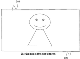
- FIG. 3 shows an example of video display displayed by the video output unit 209.
- Reference numeral 300 denotes the display device itself
- reference numeral 301 denotes display information displayed on the display device.
- FIG. 3 shows an example in which one image is displayed on the entire screen of the display device. If the video device can display 4k x 2k high-definition video, you should not perform compression or color reduction processing that degrades the image quality as much as possible.
- the transmission amount may be reduced by compression or thinning out the number of pixels as necessary.
- the multi-channel display state is extended to the E-EDID storage unit 202 as the display state of the video output unit 209, for example. It is possible. As a result, the control unit 114 of the video transmission device 100 can know the display state of the destination video reception device via the HDMI reception unit 201 and the HDMI transmission unit 113.
- Fig. 7 shows an example of extension when the E-EDID of multi-channel information is extended.
- Multi_Channel_LEN is the size (bytes) of the subsequent multi-channel information.
- the following information per channel has the following data.
- Multi_Channel_Display_Horizontal_Size_X (lower 8 bits) is the lower 8 bits of the number of horizontal pixels currently displayed.
- Multi_Channel_Display_Vertical_Size_X (lower 8 bits) is the lower 8 bits of the number of vertical pixels currently being displayed.
- Multi_Channel_Display_Horizontal_Size_X (upper 4 bits) is the upper 4 bits of the number of horizontal pixels currently displayed.
- Multi_Channel_Display_Vertical_Size_X (upper 8 bits) is the upper 4 bits of the number of vertical pixels currently displayed.
- Display_Enable_X indicates whether this channel is displaying or not.
- the control unit 114 performs lossless compression by the compression unit 112 while maintaining YCbCr4: 4: 4 because the correlation of pixels in the V direction is high.
- line-based compression for example, RLE system, ZIP system
- transmission can be performed with a compression system in a range where image quality can be completely restored.
- the video processing unit 111 thins out the color difference signal to YCbCr4: 2: 2 to transmit a transmission amount other than compression. Can be lowered.
- the video processor 111 thins out YCbCr4: 2: 0, and the transcoder 109 It is also possible to perform compression using an irreversible compression method (for example, MPEG2 / H.264).
- an irreversible compression method for example, MPEG2 / H.264.
- E-EDID is used as a means for determining the display state of the video.
- both display state communication by CEC display state communication by Ethernet I / Fs 105 and 205, etc.
- the display state of the video reception device 200 may be transmitted to the video transmission device 100 by other methods.
- the necessity of compression of the video signal transmitted from the video transmission device 100 and the change of the compression method are controlled based on the display state in the video reception device 200 .
- the necessity of compression of the video signal to be transmitted and the change of the compression method may be controlled based on the device size, resolution, and the like.
- the video transmission device 100 receives the video signal. It is possible to compress the video signal to be transmitted in accordance with the resolution of the apparatus 200.
- the method using the E-EDID described in the first embodiment, the method using the CEC communication, and the communication using the Ethernet I / Fs 105 and 205 can be considered. Other methods may be used.
- the necessity of compression of the information to be transmitted and the change of the compression method may be controlled based on the type of information to be transmitted.
- the information to be transmitted is text data
- a high compression rate can be obtained even with lossless compression, so it is possible to select lossless compression.
- the image is rough, so it is conceivable to select lossy compression.
- it is possible to select lossless compression because it is a built-in video.
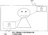
- FIG. 8 shows an example of an image displayed by the image output unit 209, in which a parent screen and a child screen are displayed at the same time.
- FIG. 8 shows a state in which the child screen is arranged in a layer in front of the parent screen.
- FIG. 9 shows a state where the display layer is switched from the state of FIG. 8, the parent screen is displayed in front, and the child screen is hidden.
- the control unit 114 of the video transmission device 100 via the HDMI reception unit 201 and the HDMI transmission unit 113 can be the destination.
- the display state of the video receiver can be known.
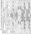
- FIG. 11 shows an example of extension when the E-EDID of multi-channel information is extended.
- Multi_Channel_LEN is the size (bytes) of the subsequent multi-channel information. Each channel has the following data as image position information.
- Multi_Channel_Display_Horizontal_Postion_X (lower 8 bits) is the lower 8 bits of the horizontal display start position that is currently displayed.
- Multi_Channel_Display_Vertical_Position_X (lower 8 bits) is the lower 8 bits of the vertical display start position currently being displayed.
- Multi_Channel_Display_Horizontal_Size_X (lower 8 bits) is the lower 8 bits of the number of horizontal pixels currently displayed.
- Multi_Channel_Display_Vertical_Size_X (lower 8 bits) is the lower 8 bits of the number of vertical pixels currently being displayed.
- Multi_Channel_Display_Horizontal_Position_X (upper 4 bits) is the upper 4 bits of the current horizontal display start position.
- Multi_Channel_Display_Vertical_Position_X (upper 4 bits) is the upper 4 bits of the vertical display start position currently being displayed.
- Multi_Channel_Display_Horizontal_Size_X (upper 4 bits) is the upper 4 bits of the number of horizontal pixels currently displayed.
- Multi_Channel_Display_Vertical_Size_X (upper 4 bits) is the upper 4 bits of the number of vertical pixels currently displayed.
- Display_Layer_X indicates the display layer of this channel. When it is 0, it is not displayed. When it is 1 or more, it indicates that the smaller the number, the more it is displayed on the front.
- the control unit 114 of the video transmission apparatus 100 displays Display_Layer_X when the child screen is hidden as shown in FIG. 9 from the state where the child screen is displayed as shown in 801 of FIG.
- the video processing unit 111 is controlled by the control unit 114 of the video transmission device 100 to stop transmission and save the bandwidth. I can do it.
- the transmission on the small screen side can be continued by the video transmitting apparatus 100 so that the position and size of the small screen can be switched at higher speed.
- the child screen is also transmitted for a certain time t after the state transition, and the child screen is not displayed after the certain time t has elapsed.
- the child screen is stopped transmission when it is in a state, it is possible to perform control that achieves both the limitation of the transmission band and the convenience of display switching.
- the example in which the display layer of the video information in the video reception apparatus 200 is transmitted to the video transmission apparatus 100 using E-EDID has been described.
- the display of the video information in the video reception apparatus 200 using another method is described.
- the layer may be transmitted to the video transmission device 100.
- a video information display layer in the video reception device 200 may be transmitted to the video transmission device 100 by using a bidirectional communication function such as communication by CEC or communication by the Ethernet I / Fs 105 and 205.
Landscapes
- Engineering & Computer Science (AREA)
- Theoretical Computer Science (AREA)
- Multimedia (AREA)
- Signal Processing (AREA)
- Physics & Mathematics (AREA)
- General Physics & Mathematics (AREA)
- Human Computer Interaction (AREA)
- General Engineering & Computer Science (AREA)
- Computer Hardware Design (AREA)
- Two-Way Televisions, Distribution Of Moving Picture Or The Like (AREA)
- Controls And Circuits For Display Device (AREA)
Abstract
Description
本願は上記課題を解決する手段を複数含んでいるが、その一例を挙げるならば、映像情報を映像受信装置へ送信する映像送信装置において、映像情報を圧縮する圧縮部と、圧縮部で圧縮した映像情報を送信する送信部と、を有し、映像受信装置における映像情報の表示状態に基づいて、圧縮部及び送信部を制御することを特徴とする。
音声出力部212は音声処理部211で処理された音声を出力するスピーカー等である。制御部214は上記のチューナー200からストレージ部213までの各部を制御する。
101 チューナー
102 Demux部
103 音声デコーダ
104 映像デコーダ
105 Ethernet I/F
106 メモリ
107 ストレージ部
108 Remux部
109 トランスコーダ
110 音声処理部
111 映像処理部
112 圧縮部
113 HDMI送信部
114 制御部
115 HDMI伝送路
200 映像受信装置
201 HDMI受信部
202 E-EDID格納部
203 チューナー
204 Demux部
205 Ethernet I/F
206 メモリ
207 映像デコーダ
208 映像処理部
209 映像出力部
210 音声デコーダ
211 音声処理部
212 音声出力部
213 ストレージ部
214 制御部
215 HDMI伝送路
300 全画面表示状態の映像表示部
301 全画面表示状態
401 子画面表示状態
501 子画面表示状態
601 非表示の子画面表示
800 子画面表示状態の映像表示部
801 子画面
901 非表示状態の子画面
1000 子画面
1001 子画面
Claims (20)
- 映像情報を映像受信装置へ送信する映像送信装置であって、
前記映像受信装置における映像情報の表示状態に基づいて、映像情報の送信を制御することを特徴とする映像送信装置。 - 映像情報を映像受信装置へ送信する映像送信装置であって、
映像情報を圧縮する圧縮部と、
圧縮部で圧縮した映像情報を送信する送信部と、を有し、
前記映像受信装置における映像情報の表示状態に基づいて、前記圧縮部及び前記送信部を制御することを特徴とする映像送信装置。 - 請求項2の映像送信装置であって、
前記送信部は複数の映像情報を送信し、
前記映像受信装置における前記複数の映像情報毎の表示状態に基づいて、前記圧縮部及び前記送信部を制御することを特徴とする映像送信装置。 - 請求項2または3の映像送信装置であって、
前記映像受信装置において表示されていない映像情報は、前記送信部から送信しないことを特徴とする映像送信装置。 - 請求項3の映像送信装置であって、
前記送信部から送信した複数の映像情報の前記映像受信装置における表示レイヤーに基づいて前記圧縮部及び前記送信部を制御することを特徴とする映像送信装置。 - 請求項5の映像送信装置であって、
前記送信部から送信した複数の映像情報のうち、前記映像受信装置において他の映像情報の背面に配置され前記映像受信装置に表示されない映像情報の送信を停止することを特徴とする映像送信装置。 - 請求項2~6のいずれかの映像送信装置であって、
前記映像受信装置が有する当該映像受信装置に関する情報を読み取る読み取り部を有し、
前記読み取り部で読み取った前記映像受信装置に関する情報に基づいて、当該映像受信装置の表示状態を判別することを特徴とする映像送信装置。 - 請求項2~6のいずれかの映像送信装置であって、
前記映像受信装置と双方向通信を行う通信部を有し、
前記通信部を介した前記映像受信装置との通信に基づいて、当該映像受信装置の表示状態を判別することを特徴とする映像送信装置。 - 映像送信装置から送信された映像情報を受信する映像受信装置であって、
前記映像送信装置から送信された映像情報の表示状態を前記映像送信装置へ伝えることを特徴とする映像受信装置。 - 映像送信装置から送信された映像情報を受信する映像受信装置であって、
映像情報を受信する受信部と、
前記受信部で受信した映像情報を処理する処理部と、
前記処理部で処理された映像情報を表示する表示部と、を有し、
前記表示部における映像情報の表示状態を前記映像送信装置へ伝えることを特徴とする映像受信装置。 - 請求項10の映像受信装置であって、
前記受信部は複数の映像情報を受信し、
前記表示部は複数の映像情報を表示し、
前記表示部における複数の映像情報の表示状態を前記映像送信装置へ伝えることを特徴とする映像受信装置。 - 請求項10または11の映像受信装置であって、
当該映像受信装置に関する情報を保持するメモリ部を有し、
前記メモリ部に保持された前記映像受信装置に関する情報は、前記表示部における映像情報の表示状態を示す情報を含むことを特徴とする映像受信装置。 - 請求項10または11の映像受信装置であって、
前記映像送信装置と双方向通信を行う通信部を有し、
前記通信部を介した前記送信装置との通信により、前記表示部における映像情報の表示状態を前記映像送信装置へ伝えることを特徴とする映像受信装置。 - 請求項11の映像受信装置であって、
前記表示部は複数の映像情報を複数のレイヤーにわけて表示し、
前記表示部における複数の映像情報の表示レイヤーを前記映像送信装置へ伝えることを特徴とする映像受信装置。 - 請求項14の映像受信装置であって、
当該映像受信装置に関する情報を保持するメモリ部を有し、
前記メモリ部に保持された前記映像受信装置に関する情報は、前記表示部における複数の映像情報の表示レイヤーを示す情報を含むことを特徴とする映像受信装置。 - 請求項14の映像受信装置であって、
前記映像送信装置と双方向通信を行う通信部を有し、
前記通信部を介した前記送信装置との通信により、前記表示部における複数の映像情報の表示レイヤーを前記映像送信装置へ伝えることを特徴とする映像受信装置。 - 映像情報を映像送信装置から映像受信装置へ送信する映像送信方法であって、
前記映像受信装置における映像情報の表示状態に基づいて、映像情報の送信を制御することを特徴とする映像送信方法。 - 映像情報を映像送信装置から映像受信装置へ送信する映像送信方法であって、
映像情報を圧縮するステップと、
圧縮した映像情報を送信するステップと、を有し、
前記映像受信装置における映像情報の表示状態に基づいて、映像情報の圧縮及び映像情報の送信を制御することを特徴とする映像送信方法。 - 映像送信装置から送信された映像情報を映像受信装置で受信する映像受信方法であって、
前記映像送信装置から送信された映像情報の前記映像受信装置における表示状態を前記映像送信装置へ伝えることを特徴とする映像受信方法。 - 映像送信装置から送信された映像情報を映像受信装置で受信する映像受信方法であって、
映像情報を受信するステップと、
前記受信部で受信した映像情報を処理するステップと、
前記処理部で処理された映像情報を表示するステップと、を有し、
前記映像情報の表示における映像情報の表示状態を前記映像送信装置へ伝えることを特徴とする映像受信方法。
Priority Applications (3)
| Application Number | Priority Date | Filing Date | Title |
|---|---|---|---|
| CN201180075024.8A CN103959810A (zh) | 2011-11-25 | 2011-11-25 | 影像发送装置、影像接收装置、影像发送方法和影像接收方法 |
| US14/359,941 US20140325583A1 (en) | 2011-11-25 | 2011-11-25 | Video transmitter apparatus and video receiver apparatus, and video transmitting method and video receiving method |
| PCT/JP2011/006556 WO2013076778A1 (ja) | 2011-11-25 | 2011-11-25 | 映像送信装置、映像受信装置、映像送信方法及び映像受信方法 |
Applications Claiming Priority (1)
| Application Number | Priority Date | Filing Date | Title |
|---|---|---|---|
| PCT/JP2011/006556 WO2013076778A1 (ja) | 2011-11-25 | 2011-11-25 | 映像送信装置、映像受信装置、映像送信方法及び映像受信方法 |
Publications (1)
| Publication Number | Publication Date |
|---|---|
| WO2013076778A1 true WO2013076778A1 (ja) | 2013-05-30 |
Family
ID=48469263
Family Applications (1)
| Application Number | Title | Priority Date | Filing Date |
|---|---|---|---|
| PCT/JP2011/006556 Ceased WO2013076778A1 (ja) | 2011-11-25 | 2011-11-25 | 映像送信装置、映像受信装置、映像送信方法及び映像受信方法 |
Country Status (3)
| Country | Link |
|---|---|
| US (1) | US20140325583A1 (ja) |
| CN (1) | CN103959810A (ja) |
| WO (1) | WO2013076778A1 (ja) |
Families Citing this family (3)
| Publication number | Priority date | Publication date | Assignee | Title |
|---|---|---|---|---|
| JP6054498B1 (ja) * | 2015-11-19 | 2016-12-27 | 東芝エレベータ株式会社 | エレベータ、およびこれに利用する映像処理装置および映像処理方法 |
| WO2020250365A1 (ja) * | 2019-06-13 | 2020-12-17 | シャープNecディスプレイソリューションズ株式会社 | 映像表示システム、情報処理装置、映像表示装置、及び映像表示方法、プログラム |
| EP4310662A1 (en) * | 2022-07-22 | 2024-01-24 | Leica Instruments (Singapore) Pte Ltd | Serialised video transmission |
Citations (1)
| Publication number | Priority date | Publication date | Assignee | Title |
|---|---|---|---|---|
| JP2001045476A (ja) * | 1999-08-02 | 2001-02-16 | Sharp Corp | 子画面表示を考慮した画像符号化装置 |
Family Cites Families (8)
| Publication number | Priority date | Publication date | Assignee | Title |
|---|---|---|---|---|
| US6678740B1 (en) * | 2000-01-14 | 2004-01-13 | Terayon Communication Systems, Inc. | Process carried out by a gateway in a home network to receive video-on-demand and other requested programs and services |
| US20050120128A1 (en) * | 2003-12-02 | 2005-06-02 | Wilife, Inc. | Method and system of bandwidth management for streaming data |
| JP2005191933A (ja) * | 2003-12-25 | 2005-07-14 | Funai Electric Co Ltd | 送信装置、送受信システム |
| KR100820678B1 (ko) * | 2006-09-28 | 2008-04-11 | 엘지전자 주식회사 | 디지털 비디오 레코더에서의 데이터 전송장치 및 방법 |
| JP5359230B2 (ja) * | 2008-02-04 | 2013-12-04 | ソニー株式会社 | 送信装置および伝送データフォーマット決定方法 |
| JP4849129B2 (ja) * | 2009-01-06 | 2012-01-11 | ソニー株式会社 | 通信装置、通信方法、プログラムおよび通信システム |
| JP5702069B2 (ja) * | 2010-03-08 | 2015-04-15 | 日立マクセル株式会社 | 映像システム、映像出力装置、及び映像出力方法 |
| US9491220B2 (en) * | 2012-07-13 | 2016-11-08 | Infosys Limited | Systems and methods for adapting mobile multimedia content delivery service |
-
2011
- 2011-11-25 US US14/359,941 patent/US20140325583A1/en not_active Abandoned
- 2011-11-25 CN CN201180075024.8A patent/CN103959810A/zh active Pending
- 2011-11-25 WO PCT/JP2011/006556 patent/WO2013076778A1/ja not_active Ceased
Patent Citations (1)
| Publication number | Priority date | Publication date | Assignee | Title |
|---|---|---|---|---|
| JP2001045476A (ja) * | 1999-08-02 | 2001-02-16 | Sharp Corp | 子画面表示を考慮した画像符号化装置 |
Also Published As
| Publication number | Publication date |
|---|---|
| CN103959810A (zh) | 2014-07-30 |
| US20140325583A1 (en) | 2014-10-30 |
Similar Documents
| Publication | Publication Date | Title |
|---|---|---|
| JP5604827B2 (ja) | 送信装置、受信装置、プログラム、及び通信システム | |
| CN101159837B (zh) | 帧率转换系统、方法以及发射器和接收器 | |
| US8984181B2 (en) | Video sender and video receiver | |
| US8730400B2 (en) | Image displaying apparatus and image processing apparatus | |
| EP2785052B1 (en) | Baseband video data transmission device and receiving device, and transceiver system | |
| WO2013076777A1 (ja) | 画像伝送装置、画像伝送方法、画像受信装置および画像受信方法 | |
| WO2010064540A1 (ja) | 送信装置および伝送データフォーマット決定方法 | |
| US9516291B2 (en) | Television systems incorporating separate A/V processing systems and television displays | |
| JP2002199359A (ja) | 信号送信装置及び信号受信装置 | |
| US20130100247A1 (en) | Image data transmission apparatus, control method for image data transmission apparatus, image data transmission method, and image data reception apparatus | |
| JP4715904B2 (ja) | 画像処理装置、画像処理方法、および通信システム | |
| WO2013076778A1 (ja) | 映像送信装置、映像受信装置、映像送信方法及び映像受信方法 | |
| WO2012147791A1 (ja) | 画像受信装置及び画像受信方法 | |
| US20110085023A1 (en) | Method And System For Communicating 3D Video Via A Wireless Communication Link | |
| US9743034B2 (en) | Video transmitting/receiving device and video display device | |
| KR20100132801A (ko) | 디지털 방송 수신 방법 및 장치 | |
| WO2012147786A1 (ja) | 画像伝送装置及び画像伝送方法 | |
| JP2015109683A (ja) | 映像送信装置、映像受信装置、映像送信方法及び映像受信方法 | |
| JPWO2013076778A1 (ja) | 映像送信装置、映像受信装置、映像送信方法及び映像受信方法 | |
| JP2013115454A (ja) | 映像送信装置、映像受信装置、映像送信方法及び映像受信方法 | |
| WO2013018249A1 (ja) | 画像伝送装置、画像伝送方法、画像受信装置および画像受信方法 | |
| JP2013115452A (ja) | 映像データの送受信方法、映像送信装置、及び映像受信装置 | |
| KR20040000313A (ko) | 시청각 정보를 기록 및 판독하는 시스템 | |
| JP2013115453A (ja) | 画像伝送装置、画像伝送方法、画像受信装置および画像受信方法 |
Legal Events
| Date | Code | Title | Description |
|---|---|---|---|
| 121 | Ep: the epo has been informed by wipo that ep was designated in this application |
Ref document number: 11876307 Country of ref document: EP Kind code of ref document: A1 |
|
| ENP | Entry into the national phase |
Ref document number: 2013545659 Country of ref document: JP Kind code of ref document: A |
|
| NENP | Non-entry into the national phase |
Ref country code: DE |
|
| WWE | Wipo information: entry into national phase |
Ref document number: 14359941 Country of ref document: US |
|
| 122 | Ep: pct application non-entry in european phase |
Ref document number: 11876307 Country of ref document: EP Kind code of ref document: A1 |