WO2013064033A1 - 粒子分析仪及其粒子测试控制方法、装置 - Google Patents
粒子分析仪及其粒子测试控制方法、装置 Download PDFInfo
- Publication number
- WO2013064033A1 WO2013064033A1 PCT/CN2012/083512 CN2012083512W WO2013064033A1 WO 2013064033 A1 WO2013064033 A1 WO 2013064033A1 CN 2012083512 W CN2012083512 W CN 2012083512W WO 2013064033 A1 WO2013064033 A1 WO 2013064033A1
- Authority
- WO
- WIPO (PCT)
- Prior art keywords
- sample
- counting
- test
- control
- plugging
- Prior art date
- Legal status (The legal status is an assumption and is not a legal conclusion. Google has not performed a legal analysis and makes no representation as to the accuracy of the status listed.)
- Ceased
Links
Images



Classifications
-
- G—PHYSICS
- G01—MEASURING; TESTING
- G01N—INVESTIGATING OR ANALYSING MATERIALS BY DETERMINING THEIR CHEMICAL OR PHYSICAL PROPERTIES
- G01N27/00—Investigating or analysing materials by the use of electric, electrochemical, or magnetic means
- G01N27/26—Investigating or analysing materials by the use of electric, electrochemical, or magnetic means by investigating electrochemical variables; by using electrolysis or electrophoresis
- G01N27/416—Systems
- G01N27/4163—Systems checking the operation of, or calibrating, the measuring apparatus
-
- G—PHYSICS
- G01—MEASURING; TESTING
- G01N—INVESTIGATING OR ANALYSING MATERIALS BY DETERMINING THEIR CHEMICAL OR PHYSICAL PROPERTIES
- G01N15/00—Investigating characteristics of particles; Investigating permeability, pore-volume or surface-area of porous materials
- G01N15/10—Investigating individual particles
- G01N15/1031—Investigating individual particles by measuring electrical or magnetic effects
- G01N15/12—Investigating individual particles by measuring electrical or magnetic effects by observing changes in resistance or impedance across apertures when traversed by individual particles, e.g. by using the Coulter principle
-
- G—PHYSICS
- G01—MEASURING; TESTING
- G01N—INVESTIGATING OR ANALYSING MATERIALS BY DETERMINING THEIR CHEMICAL OR PHYSICAL PROPERTIES
- G01N15/00—Investigating characteristics of particles; Investigating permeability, pore-volume or surface-area of porous materials
- G01N15/10—Investigating individual particles
- G01N15/1031—Investigating individual particles by measuring electrical or magnetic effects
- G01N15/12—Investigating individual particles by measuring electrical or magnetic effects by observing changes in resistance or impedance across apertures when traversed by individual particles, e.g. by using the Coulter principle
- G01N2015/137—Cleaning
-
- G—PHYSICS
- G01—MEASURING; TESTING
- G01N—INVESTIGATING OR ANALYSING MATERIALS BY DETERMINING THEIR CHEMICAL OR PHYSICAL PROPERTIES
- G01N15/00—Investigating characteristics of particles; Investigating permeability, pore-volume or surface-area of porous materials
- G01N15/10—Investigating individual particles
- G01N15/1031—Investigating individual particles by measuring electrical or magnetic effects
- G01N15/12—Investigating individual particles by measuring electrical or magnetic effects by observing changes in resistance or impedance across apertures when traversed by individual particles, e.g. by using the Coulter principle
- G01N2015/138—Detecting blocking debris
Definitions
- the invention relates to the field of biochemical analysis, in particular to a particle analyzer and a test control method thereof.
- Particle analyzers are used in the field of biochemical analysis involved in medical or biochemical research. They are used to classify and count the tiny particles of each component in the mixture, and more common particle analyzers such as blood cell analyzers.
- a blood cell analyzer is an instrument for counting and classifying human blood cells by adding a quantitative blood sample to a certain amount of a diluent having a cell morphology and a conductive property, and then the mixed liquid is The micro-pores are driven by the power driving source. Because the cells have weak conductive properties, the equivalent impedance in the micro-holes will become larger when passing through the micro-holes.
- the voltage changes and the impedance
- the change is proportional, that is, the waveform of the voltage reflects the impedance change process of the particles passing through the micropore.
- a voltage pulse is generated.
- the height of the voltage pulse reflects the volume of the particle, so according to the voltage pulse.
- the amplitude classifies the particles. This measurement method is referred to as the impedance method.
- the microporous element used in the detection process is a valuable element with a pore diameter of 50-120 um. Due to its small pore size, the micropores are easily infected by various proteins, cell debris and blood in the blood during the detection process. Clots, oily lipids, and debris formed during the puncture of the test tube are clogged. This condition is called plugging, which can affect the reliability of the instrument's detection function.
- the current blood cell analyzer test procedure and timing are shown in Figure 1. First, the first sample and the specified dilution are added to the reaction cell for dilution and incubation, and then the diluted quantitative sample is injected from the reaction cell.
- the current treatment method is to re-position the first sample that has been blocked by the manual or sample rack retraction mechanism to the position to be tested.
- the invention provides a particle analyzer and a test control method and device thereof for reducing the probability of plugging.
- a particle analyzer test control method comprising:
- the dosing system is controlled to suck the sample from the reaction tank again and inject into the counting pool, and then restart the impedance counting test on the sample in the counting pool.
- a particle test control apparatus for a particle analyzer comprising:
- a first control unit configured to control the dosing system to draw the diluted sample from the reaction pool and inject into the counting pool;
- a second control unit coupled to the first control unit for controlling the liquid discharge control valve of the reaction tank to remain in a closed state after the first control unit controls the liquid addition system to draw the diluted sample from the reaction chamber, so that the remaining dilution The subsequent sample remains in the reaction cell;
- a third control unit coupled to the first control unit, for controlling the sample in the counting pool to start an impedance method counting test after the sample is injected into the counting pool;
- the plugging monitoring unit is configured to receive the sample to perform the micropore voltage output during the impedance method of the impedance test, determine whether a plugging occurs, and output a plugging event when the plugging occurs;
- the fourth control unit is coupled to the plugging hole monitoring unit, configured to control the pause test according to the plugging event, and perform the plugging operation, and output a control signal to the first control unit after the plugging operation is completed, so that the first control unit controls the adding
- the liquid system again draws the sample from the reaction cell and injects it into the counting cell.
- a particle analyzer is also provided, including:
- reaction tank for diluting a sample injected therein, the reaction tank comprising a pipette, an outlet pipe and a drain pipe, the drain pipe being provided with a switchable state between the closed state and the open state according to the control signal Switched drain control valve;
- An impedance method counting test system comprising a counting pool, wherein the impedance method counting test system performs an impedance method counting test on a sample injected into the counting pool, and outputs a micropore voltage;
- a dosing system for drawing a diluted sample from the reaction cell and injecting it into the counting cell
- a signal processing and control device for receiving a micropore voltage and performing shaping processing and signal recognition, the signal processing and control device being configured to control after the dosing system draws the diluted sample from the reaction cell and injects into the counting pool
- the drain control valve of the reaction tank is maintained in a closed state, so that the remaining diluted sample remains in the reaction tank, and whether the plugging occurs according to the micropore voltage during the counting test is controlled, and when the plugging occurs, the control is performed. Suspend the test of the next sample and perform the plugging operation. After the plugging operation is completed, the dosing system is controlled to take the sample from the reaction tank again and inject it into the counting pool, and then restart the impedance counting of the sample in the counting pool. test.
- a particle test control method for a particle analyzer comprising:
- the sucked sample is subjected to multi-stage dilution by injecting into a plurality of reaction cells until a diluted sample conforming to the dilution ratio is formed in the last stage reaction cell;
- a diluted sample that meets the dilution ratio is obtained in a reaction cell in which the remaining diluted sample is left;
- the diluted sample that meets the dilution ratio is injected into the counting cell, and then the sample in the counting cell is restarted for the impedance counting test.
- a particle test control method for a particle analyzer comprising:
- the dosing system is controlled to inject the diluted sample retained therein into the counting pool, and then restart the impedance counting test on the samples in the counting pool.
- FIG. 1 is a test sequence diagram of a blood cell analyzer in an embodiment
- FIG. 2 is a schematic structural view of a blood cell analyzer according to an embodiment of the present invention.
- Figure 3 is a schematic diagram of particle identification and statistical results
- 4a is a schematic diagram of a stable electric field formed by a constant current source
- Figure 4b is a schematic diagram of a pulse signal formed when blood cells pass through the micropore
- Figure 4c is a schematic diagram showing the increase of the micropore voltage when the hole is blocked
- Figure 4d is a schematic diagram of abnormal fluctuation of micropore voltage when plugging holes
- FIG. 5a is a schematic structural diagram of a particle test control apparatus according to an embodiment of the present invention.
- FIG. 5b is a schematic structural diagram of a particle test control apparatus according to another embodiment of the present invention.
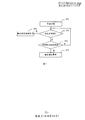
- FIG. 6 is a flow chart of particle testing in an embodiment of the present invention.
- FIG. 7 is a flow chart of monitoring a plugging hole according to an embodiment of the present invention.
- Figure 8 is a timing chart of testing of a blood cell analyzer in an embodiment of the present invention.
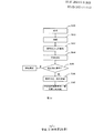
- Figure 10 is a flow chart of particle testing in accordance with yet another embodiment of the present invention.
- the relevant test information is monitored in real time during the counting process of the particles, and the test of the sample is suspended after the hole is found, and the plugging process is immediately performed, and then the diluted sample remaining after the sample is diluted is used for the second time.
- the secondary test avoids the sample from being able to output the test result due to the plugging that occurs during the first measurement, and does not need to reposition the sample to the position to be tested for re-absorption and heavy dilution, thereby reducing the probability of plugging.
- the method of fully utilizing the diluted sample remaining after dilution of the sample may be that the sample remaining in the reaction pool is not immediately discharged after the sample is taken from the reaction pool, but is waited for the sample test result to be discharged. If there is a plugging during the test, the remaining diluted sample is taken from the reaction tank after the plugging for the second test.
- the method of making full use of the diluted sample remaining after dilution of the sample may also be to utilize the remaining diluted sample stored in the dosing system conduit from the reaction cell to the counting cell.
- the particle analyzer is described below as an example of a blood cell analyzer.
- the blood cell analyzer includes a reaction cell 2, a dosing system 3, an impedance method counting test system 4, and a signal processing and control device 5.
- the sample loading system 1 performs aspirating operation on the sample placed at the position to be tested, draws a quantitative sample, and injects the aspirated sample into the reaction cell 2, and the reaction cell 2 dilutes the sample and the diluent injected therein, Multi-stage dilution is performed until the desired dilution ratio is reached.
- the impedance method counting test system 4 includes a counting cell 41.
- the reaction cell 2 adds the diluted sample to the counting cell 41 through the dosing system 3, and the impedance method counting test system 4 performs an impedance method counting test on the sample in the injection counting cell 41, and outputs Micropore voltage.
- the reaction cell 2 includes an inlet pipe 21, an outlet pipe 22, and a drain pipe 23, and an inlet pipe 21 and a coupling system 1 coupled to the dosing system 3 for draining
- the pipe 23 is provided with a drain control valve 231 that is switchable between a closed state and an open state in accordance with a control signal.
- the impedance method counting test system 4 includes a counting cell 41, a power source driver 42 and an anode electrode 43, and a cathode electrode 44.
- the counting cell 41 includes a front cell 411, a back cell 412, and a micropore element 413 between the front cell 411 and the back cell 412. .
- the counting cell front cell 411 and the counting cell back cell 412 contain an electrolytic solution 45, one end of which is located in the pre-particle counting cell 411, and one end of the cathode electrode 44 is located in the particle counting back cell 412, and the anode electrode 43
- the other end and the other end of the cathode electrode 44 are connected to the output of the power source drive 42, which is typically a constant current source.
- the counting pool rear tank 412 is further provided with a liquid outlet 414 that communicates with the negative pressure chamber.
- the signal processing and control device 5 receives the micropore voltage and performs processing such as shaping processing and signal recognition, and finally forms identification and statistical results. For example, as shown in FIG. 3, the result can be directly printed out or output to the display for the operator to view. Identification and statistical results can also be stored for later review.
- the instrument takes a quantitative blood sample from the blood collection tube and mixes it with the quantitative dilution solution in the reaction tank to form a diluted blood sample with a fixed dilution ratio; then, a certain amount of the diluted blood sample is injected from the reaction tank into the counting pool for impedance counting, and then the count is obtained. result.
- a certain amount of reagent is mixed to form a second diluted sample, and then flows from the front cell 411 through the micropores in the micropore element 413 to the back pool 412 under the action of the negative pressure.
- the diluted blood sample flows from the front pool 411 into the back pool 412 to form a stable flow field.
- FIG. a Since a constant current source is applied between the anode electrode 43 and the cathode electrode 44, a stable electric field is formed, as shown in FIG. a is shown.
- a pulse signal is formed when blood cells pass through the microwell, as shown in Figure 4b.
- the micropore voltage rises or fluctuates abnormally when foreign matter is blocked in front of the microporous element, as shown in Figures 4c and 4d.
- the signal processing and control device 5 is further configured to control the drain control valve 231 of the reaction cell 2 to be maintained after the dosing system 3 draws the diluted sample from the reaction cell 2 and injects into the counter cell 41. In the off state, the remaining diluted sample remains in the reaction cell 2, and whether the plugging occurs according to the micropore voltage during the counting test, and the control of the next sample is suspended when the plugging occurs. And performing the plugging operation, after the draining operation is completed, the dosing system 3 is controlled to take the sample from the reaction cell 2 again and inject it into the counting cell 41, and then restart the impedance counting test on the sample in the counting cell 41.
- the signal processing and control device includes a particle test control device 50.
- the particle test control device 50 includes a first control unit 51, a second control unit 52, a third control unit 53, and a block. Hole monitoring unit 54 and fourth control unit 55.
- the first control unit 51 is configured to control the dosing system 3 to draw the diluted sample from the reaction cell and inject into the counting cell;
- the second control unit 52 is coupled to the first control unit 51 for controlling the dosing system at the first control unit 51.
- the drain control valve 231 controlling the reaction cell continues to be in a closed state so that the remaining diluted sample remains in the reaction cell;
- the third control unit 53 is coupled to the first control unit 51.
- the sample in the counting pool starts the impedance method counting test, which may also be referred to as a data acquisition control unit;
- the blocking hole monitoring unit 54 is configured to receive the sample for the impedance method. Counting the micropore voltage output during the test to determine whether a plugging occurs, and outputting a plugging event when the plugging occurs;
- the fourth control unit 55 is coupled to the plugging monitoring unit 54 for controlling the pause of the sample according to the plugging event Testing, and performing the plugging operation, outputting a control signal to the first control unit 51 after the draining operation is completed, so that the first control unit 51 controls the liquid adding system to reverse again Sample injection and suction cell counting cell.
- the first control unit 51 controls the liquid adding system to take the sampling from the reaction pool again, and then controls the second control unit 52 to output the emptying control signal, and controls the liquid discharging control valve of the reaction pool to switch to the open state to evacuate the remaining in the reaction pool.
- the diluted sample is controlled.
- the first control unit 51 may be a motor control unit that controls the motor operation of the liquid addition system 3 to draw the diluted sample from the reaction chamber and inject it into the counting pool as a motor control.
- the unit which can also control other parts of the motor according to control commands, such as the impedance method to count the motor in the test system.
- the second control unit 52 may be a valve control unit for controlling the closing and opening of the drain control valve 231 of the reaction cell.
- the valve control unit may also control other parts of the control valve according to the control command, such as controlling impedance counting. Test the valve in the system or the valve in the dosing system 3.
- the particle test control device further includes a timer 56 coupled to the third control unit 53 and the fourth control unit 55, respectively, the third control unit 53 being in the counter pool
- the control timer 56 starts counting.
- the timer 56 outputs a timing signal to the fourth control unit 55 after the timing reaches the set time, and the fourth control unit 55 receives the set time.
- the plugging event is reached, the test of the suspended sample is controlled, and the draining operation is performed, and after the draining operation is completed, the control signal is output to the first control unit 51, so that the first control unit 51 controls the liquid adding system 3 to again from the reaction pool. Sampling the sample and injecting it into the counting cell.
- the second control unit 52 is controlled to output the emptying control signal, and the drain control valve 231 of the control reaction tank is switched to the open state to evacuate the reaction pool. The remaining diluted sample.
- the timer may be integrated in the signal processing and control device, may be integrated in the particle test control device, may not be integrated in the particle test control device, or may exist as a discrete component outside the signal processing and control device.
- the method of testing the particles is as shown in FIG. 6, and includes the following steps:
- step S61 the sample suction system is controlled to perform a sample suction operation on the sample placed in the position to be tested.
- step S62 the aspirated sample is injected into the reaction cell for dilution.
- step S63 the dosing system is controlled to draw the diluted sample from the reaction cell and inject into the counting cell, while controlling the liquid discharging control valve of the reaction cell to remain in the closed state, so that the remaining diluted sample remains in the reaction cell.
- Step S64 performing an impedance method counting test on the samples in the counting pool, and performing step S65 in the counting test.
- step S65 it is determined whether a hole blocking event occurs. If a hole blocking event occurs, step S66 is performed, otherwise step S68 is performed.
- the plugging event is output.
- the set time may be the time T of the extracted diluted sample all passing through the microwell, or may be less than the time T of the extracted diluted sample all passing through the microwell.
- the set time can be determined according to the performance of the instrument and the subsequent algorithm for signal extraction and recognition. It is sufficient to collect accurate and reliable particle counts and classifications according to the signals collected during the set time. For example, the extracted diluted samples are all passed.
- the time of the micropore is T, and the set time can be T/2 depending on the performance of the instrument and the algorithm used for subsequent signal extraction and recognition.
- the process of monitoring the plugging holes within the set time is as shown in FIG. 7, and includes the following steps:
- Step S71 starting timing after starting the test by using the impedance method
- step S72 it is determined whether the set time is up. If the set time is up, step S74 is executed to output the emptying control signal, otherwise step S73 is performed to determine the micropore voltage detected in real time.
- step S73 the micropore voltage detected in real time is judged during the counting test.
- step S75 is performed to output a plugging event. Otherwise, the process proceeds to step S72.
- step S66 when the plugging event occurs, the sample test is suspended, including the ongoing sample test and the test of the next sample, and the plugging operation is performed.
- Step S67 after the plugging operation is completed, the dosing system is controlled to suck the sample from the reaction pool again and inject into the counting pool, and then restart the impedance counting test on the sample in the counting pool.
- the emptying control signal can also be output, and step S68 is performed. Or continue to monitor whether a plugging event occurs during the impedance measurement test of the sample in the counting pool again, until step S68 is performed after the sample test is successful.
- step S68 the drain control valve of the control reaction tank is switched to the open state to evacuate the remaining diluted sample in the reaction tank.
- the micropore voltage detected in real time it is determined that there are various schemes for blocking the hole.
- the micropore voltage can be determined according to the combination of the amplitude of the micropore voltage detected in real time, the baseline voltage, and the pulse shape. Whether it is abnormal or not, it is judged that a hole is blocked when the voltage is abnormal. E.g:
- Determining whether a hole is blocked according to the amplitude of the micropore voltage detected in real time includes the following steps: comparing the amplitude of the micropore voltage with a first threshold; and when the amplitude of the micropore voltage exceeds the first threshold, recording the amplitude of the micropore exceeds a duration of the first threshold; comparing the duration to a second threshold; and determining that a plugging event occurs when the duration exceeds the second threshold.
- the step of determining a baseline voltage of the micropore voltage detected in real time includes: calculating a baseline voltage of the micropore voltage; comparing the baseline voltage with a third threshold; and considering that the baseline voltage is greater than a third threshold Hole event.
- the test sequence of the sample can be as shown in Figure 8.
- the quantitative reagent and the quantified blood sample of the first sample are separately injected into the reaction tank for mixing and incubation to obtain a dilution that meets the prescribed dilution ratio.
- sample. A quantitative dilution sample is taken from the reaction tank and injected into the counting cell for counting test.
- the reaction tank is not immediately emptied, but the discharge control valve of the control tank is maintained in the closed state, so that the remaining diluted sample remains in the reaction tank.
- the second test is used after plugging. During the test, it is monitored whether the hole is blocked within the set time.
- the diluted sample is taken from the reaction tank for the second time to be injected into the counting pool for counting test. If the plugging is not performed within the set time, or after the second dilution of the diluted sample is taken from the reaction tank, the control tank is controlled to switch to the open state, and the reaction tank is evacuated. The evacuated reaction cell is cleaned, and then the second sample is tested, and the quantitative reagent and the quantified second sample blood sample are separately injected into the reaction cell for mixing and incubation.
- the remaining sample can be extracted for the second time after the first dilution of the sample, so it is not necessary to find the sample that has been blocked and place it again.
- the sample to be tested is subjected to re-absorption and re-dilution, thereby reducing the probability of plugging. And because there is no second blood sample, the sample demand is reduced, reducing the minimum blood draw requirement of the test subject.
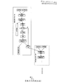
- the cell analyzer has a plurality of reaction cells of multiple dilutions, and the method of testing the particles is as shown in FIG. 9, and includes the following steps:
- step S91 the sample suction system is controlled to perform a sample suction operation on the sample placed in the position to be tested.
- step S92 the aspirated sample is subjected to multi-stage dilution by injecting into a plurality of reaction cells until a diluted sample conforming to the dilution ratio is formed in the final stage reaction cell.
- the dilution of the sample is not completed in one reaction cell, and multi-stage dilution is required through multiple reaction cells, that is, the quantitative sample and the quantitative reagent are separately injected into the first reaction cell to perform the first-stage mixing.
- incubating then taking a quantitative first-stage dilution sample from the first reaction cell and then injecting the quantitative reagent into the second reaction cell for the second-stage mixing and incubation, until a diluted sample conforming to the dilution ratio is formed.
- the diluted sample in the last stage of the reaction is the diluted sample that meets the dilution ratio.
- Step S93 controlling the liquid adding system to take the diluted sample from the last stage reaction pool and injecting into the counting pool, and controlling the liquid discharging control valve of at least one of the plurality of reaction cells to remain in the closed state, so that the remaining diluted sample is Continue to remain in the reaction cell.
- the drain control valve of the last stage reaction tank can be kept in the closed state, and the remaining dilution sample can be kept in the last stage reaction tank, and the discharge control valve of the other stage reaction tank can be kept closed. The remaining intermediate level of diluted sample is retained in the reaction cell.
- Step S94 performing an impedance method counting test on the samples in the counting pool.
- step S95 it is monitored whether a plugging event occurs during the counting test.
- the scheme for judging whether or not a plugging event occurs may be the same as the above embodiment.
- step S96 when the plugging event occurs, the test of the suspended sample is controlled, and the plugging operation is performed.
- step S97 a diluted sample conforming to the dilution ratio is obtained in the reaction cell in which the remaining diluted sample is left. If, in step S93, the remaining diluted sample is retained in the last stage of the reaction, the diluted sample is taken from the last stage of the reaction, which is originally a diluted sample that meets the dilution ratio, so that dilution is not required. If in step S93, the remaining intermediate level dilution sample is retained in the other stage of the reaction cell, the diluted sample is taken from the reaction cell, but since the extracted diluted sample is not yet a diluted sample that meets the dilution ratio, it is also required Dilute until a diluted sample that meets the dilution ratio is formed. The diluted sample that meets the dilution ratio is injected into the counting cell, and then the sample in the counting cell is restarted to perform the impedance counting test again.
- step S98 all reaction cells are emptied.
- steps S67 and S72 determine whether or not a hole is blocked.
- the cell analyzer has a long pipe dosing system, and the method of testing the particles is as shown in FIG. 10, and includes the following steps:
- Step S101 the sample suction system is controlled to perform a sample suction operation on the sample placed in the position to be tested.
- step S102 the sucked sample is injected into the reaction cell for dilution.
- step S103 the dosing system is controlled to draw the diluted sample from the reaction cell and inject into the counting cell, while allowing the dosing system to retain the partially diluted sample.
- a control valve can be provided in the pipe of the dosing system. When the diluted sample is added to the counting cell for the first time, the control valve disposed at both ends of the pipe can be closed, so that the remaining diluted sample in the pipe is closed in the pipe.
- the control valves at both ends of the control line are opened and the remaining diluted sample in the line is injected into the counting cell. It is also possible to set the control valve only at the end of the dosing system close to the counting cell. After the diluted sample is added to the counting cell for the first time, the valve is closed, so that the remaining diluted sample in the pipe is enclosed in the pipe, when the second is needed. When the diluted sample is added to the counting cell, the valve is controlled to open and the remaining diluted sample in the pipe is injected into the counting cell.
- a syringe or pneumatic device can be used to connect the dosing system to control the discharge of the diluted sample to the counting cell or to remain in the tubing of the dosing system by controlling the movement of the syringe or pneumatic device.
- Step S104 performing an impedance method counting test on the samples in the counting pool, and monitoring whether a plugging event occurs during the counting test.
- the scheme for judging whether or not a plugging event occurs may be the same as the above embodiment.
- step S105 when a plugging event occurs, the test is suspended and the draining operation is performed.
- Step S106 after the draining operation is completed, the dosing system is controlled to inject the diluted sample retained therein into the counting pool, and then restart the impedance method counting test on the samples in the counting pool.
- reaction cell it is not necessary to consider when the reaction cell is emptied, and the reaction cell may be emptied after the sample is taken therefrom for the first time, or may be emptied for some time.
- steps S67 and S72 determine whether or not a hole is blocked.
- the particle test control device 50 controls the changeover switch 45 to switch from the power source drive 42 to the ignition circuit 46, thereby forming a local high temperature at the micropores of the microporous member, even making the liquid Boiling, thereby destroying the foreign body structure near the micropores.
- the voltage on both sides of the micropore element in the measurement process is monitored in real time during the counting process; when the voltage on both sides of the microporous element is abnormally increased or abnormally fluctuated, it is considered that the micropore has been blocked at the time.
- the sample test is suspended (in continuous injection mode), and after the necessary action is completed, the plugging process is performed immediately, and then the retained sample is re-extracted to dilute the remaining diluted sample for the first time and retested. .
- the instrument automatically resumes testing for the next sample.
- the particle analyzer may be another body fluid analyzer such as an analysis station or a urine analyzer.
Landscapes
- Chemical & Material Sciences (AREA)
- Health & Medical Sciences (AREA)
- Life Sciences & Earth Sciences (AREA)
- General Physics & Mathematics (AREA)
- Physics & Mathematics (AREA)
- Analytical Chemistry (AREA)
- Biochemistry (AREA)
- General Health & Medical Sciences (AREA)
- Immunology (AREA)
- Pathology (AREA)
- Dispersion Chemistry (AREA)
- Molecular Biology (AREA)
- Chemical Kinetics & Catalysis (AREA)
- Electrochemistry (AREA)
- Investigating Or Analysing Biological Materials (AREA)
- Investigating Or Analyzing Materials By The Use Of Electric Means (AREA)
Abstract
Description
Claims (20)
- 用于粒子分析仪的粒子测试控制方法,其特征在于包括:控制吸样系统对放置在待测试位的样本进行吸样操作;将吸取的样本注入反应池进行稀释;控制加液系统从反应池吸取稀释后的样本并注入计数池,同时控制反应池的排液控制阀继续处于关闭状态,以使剩余的稀释后的样本继续保留在反应池中;对计数池中的样本进行阻抗法计数测试,并在计数测试过程中监测是否发生堵孔事件;当发生堵孔事件时则控制暂停样本的测试,并执行排堵操作;在排堵操作完成后控制加液系统再次从反应池中吸取样本并注入计数池,然后重新开始对计数池中的样本进行阻抗法计数测试。
- 如权利要求1所述的方法,其特征在于,控制加液系统再次从反应池中吸取样本后输出排空控制信号,控制反应池的排液控制阀切换到打开状态,以排空反应池中剩余的稀释后的样本。
- 如权利要求1或2所述的方法,其特征在于,在对计数池中的样本采用阻抗法开始测试后设定时间内监测到堵孔时,则输出堵孔事件。
- 如权利要求1-3中任一项所述的方法,其特征在于,如果在设定时间内没有接收到堵孔事件,则输出排空控制信号,控制反应池的排液控制阀切换到打开状态,以排空反应池中剩余的稀释后的样本。
- 如权利要求4所述的方法,其特征在于,所述在计数测试过程中监测是否发生堵孔事件包括:在采用阻抗法开始测试后即开始计时;在计时过程中对实时检测到的微孔电压进行判断,当判断微孔电压异常时输出堵孔事件;判断设定时间是否到,若是则输出排空控制信号,否则继续对实时检测到的微孔电压进行判断。
- 如权利要求5所述的方法,其特征在于,对实时检测到的微孔电压进行判断包括:根据实时检测到的微孔电压的幅度、基线电压和脉冲形态中的任一种或多种的组合判断微孔电压是否异常。
- 用于粒子分析仪的粒子测试控制装置,其特征在于包括:第一控制单元,用于控制加液系统从反应池吸取稀释后的样本并注入计数池;第二控制单元,用于在第一控制单元控制加液系统从反应池吸取稀释后的样本后控制反应池的排液控制阀继续处于关闭状态,以使剩余的稀释后的样本继续保留在反应池中;第三控制单元,用于在样本注入计数池后控制计数池中的样本开始阻抗法计数测试;堵孔监测单元,用于接收样本进行阻抗法计数测试过程中输出的微孔电压,判断是否发生堵孔,当发生堵孔时则输出堵孔事件;第四控制单元,耦合到堵孔监测单元,用于根据堵孔事件控制暂停测试,并执行排堵操作,在排堵操作完成后输出控制信号至第一控制单元,使第一控制单元控制加液系统再次从反应池中吸取样本并注入计数池。
- 如权利要求7所述的装置,其特征在于,所述第一控制单元控制加液系统再次从反应池中吸取样本后控制第二控制单元输出排空控制信号,控制反应池的排液控制阀切换到打开状态,以排空反应池中剩余的稀释后的样本。
- 如权利要求7或8所述的装置,其特征在于,所述粒子测试控制装置还包括定时器,所述定时器分别耦合到第三控制单元和第四控制单元,所述第三控制单元在对计数池中的样本采用阻抗法开始测试后即控制定时器开始计时,所述定时器在计时到达设定时间后输出定时信号至第四控制单元,所述第四控制单元在设定时间内接收到堵孔事件时,则控制暂停样本的测试,并执行排堵操作,在排堵操作完成后输出控制信号至第一控制单元,使第一控制单元控制加液系统再次从反应池中吸取样本并注入计数池。
- 如权利要求9所述的装置,其特征在于,所述第四控制单元在设定时间内没有接收到堵孔事件时则控制第二控制单元输出排空控制信号,控制反应池的排液控制阀切换到打开状态,以排空反应池中剩余的稀释后的样本。
- 如权利要求10所述的装置,其特征在于,所述在计数测试过程中监测是否发生堵孔事件包括:在采用阻抗法开始测试后即开始计时;在计时过程中对实时检测到的微孔电压进行判断,当判断微孔电压异常时输出堵孔事件;判断设定时间是否到,若是则输出排空控制信号,否则继续对实时检测到的微孔电压进行判断。
- 如权利要求11所述的装置,其特征在于,对实时检测到的微孔电压进行判断包括:根据实时检测到的微孔电压的幅度、基线电压和脉冲形态中的任一种或多种的组合判断微孔电压是否异常。
- 一种粒子分析仪, 其特征在于包括:反应池,用于对注入其中的样本进行稀释,所述反应池包括吸液管、出液管和排液管,所述排液管上设置有可根据控制信号在关闭状态和打开状态之间切换的排液控制阀;阻抗法计数测试系统,其包括计数池,所述阻抗法计数测试系统对注入计数池的样本进行阻抗法计数测试,输出微孔电压;加液系统,其用于从反应池吸取稀释后的样本并注入计数池;信号处理及控制装置,其用于接收微孔电压并进行整形处理和信号识别,所述信号处理及控制装置被配置为在加液系统从反应池吸取稀释后的样本并注入计数池后仍控制反应池的排液控制阀维持在关闭状态,以使剩余的稀释后的样本继续保留在反应池中,并在计数测试过程中根据微孔电压监测是否发生堵孔,当发生堵孔时则控制暂停下一样本的测试,并执行排堵操作,在排堵操作完成后控制加液系统再次从反应池中吸取该样本并注入计数池,然后重新开始对计数池中的该样本进行阻抗法计数测试。
- 如权利要求13所述的粒子分析仪,其特征在于,所述信号处理及控制装置被配置为控制加液系统再次从反应池中吸取样本后输出排空控制信号至排液控制阀,控制排液控制阀切换到打开状态,以排空反应池中剩余的稀释后的样本。
- 如权利要求13或14所述的粒子分析仪,其特征在于,所述粒子分析仪还包括定时器,所述定时器耦合到所述信号处理及控制装置,所述信号处理及控制装置在对计数池中的样本采用阻抗法开始测试后即控制定时器开始计时,所述定时器在计时到达设定时间后输出定时信号至信号处理及控制装置,所述信号处理及控制装置被配置为在设定时间内监测到堵孔时,则控制暂停样本的测试,并执行排堵操作,在排堵操作完成后控制加液系统再次从反应池中吸取该样本并注入计数池,然后重新开始对计数池中的该样本进行阻抗法计数测试。
- 如权利要求15所述的粒子分析仪,其特征在于,所述信号处理及控制装置被配置为如果在设定时间内没有监测到堵孔,则输出排空控制信号,控制反应池的排液控制阀切换到打开状态,以排空反应池中剩余的稀释后的样本。
- 如权利要求13所述的粒子分析仪,其特征在于,所述信号处理及控制装置被配置为根据实时检测到的微孔电压的幅度、基线电压和脉冲形态中的任一种或多种的组合判断是否发生堵孔。
- 用于粒子分析仪的粒子测试控制方法,其特征在于包括:控制吸样系统对放置在待测试位的样本进行吸样操作;将吸取的样本通过注入多个反应池进行多级稀释,直到在最末级反应池中形成符合稀释比的稀释样本;控制加液系统从最末级反应池吸取稀释后的样本并注入计数池,控制多个反应池中的至少一个的排液控制阀继续处于关闭状态,以使剩余的稀释后的样本继续保留在该反应池中;对计数池中的样本进行阻抗法计数测试,并在计数测试过程中监测是否发生堵孔事件;当发生堵孔事件时则控制暂停样本的测试,并执行排堵操作;基于留有剩余的稀释后的样本的反应池中得到符合稀释比的稀释样本;将符合稀释比的稀释样本注入计数池,然后重新开始对计数池中的样本进行阻抗法计数测试。
- 用于粒子分析仪的粒子测试控制方法,其特征在于包括:控制吸样系统对放置在待测试位的样本进行吸样操作;将吸取的样本注入反应池进行稀释;控制加液系统从反应池吸取稀释后的样本,然后将稀释后的样本的一部分注入计数池,并使加液系统保留剩余的稀释后的样本;对计数池中的样本进行阻抗法计数测试,并在计数测试过程中监测是否发生堵孔事件;当发生堵孔事件时则控制暂停样本的测试,并执行排堵操作;在排堵操作完成后控制加液系统将其中保留的稀释后的样本注入计数池,然后重新开始对计数池中的样本进行阻抗法计数测试。
- 如权利要求19所述的方法,其特征在于:所述加液系统的管道两端设置控制阀,当控制加液系统从反应池吸取稀释后的样本并注入计数池后,控制管道两端的控制阀关闭,当排堵操作完成后,控制管道两端的控制阀打开,使剩余在管道中的稀释样本被注入到计数池中。
Priority Applications (4)
| Application Number | Priority Date | Filing Date | Title |
|---|---|---|---|
| US14/355,547 US9714916B2 (en) | 2011-10-31 | 2012-10-25 | Particle analyzers and particle test control methods and devices thereof |
| US15/603,384 US10613051B2 (en) | 2011-10-31 | 2017-05-23 | Particle analyzers and particle test control methods and devices thereof |
| US16/831,619 US11644436B2 (en) | 2011-10-31 | 2020-03-26 | Particle analyzers and particle test control methods and devices thereof |
| US18/138,230 US20240125734A1 (en) | 2011-10-31 | 2023-04-24 | Particle analyzers and particle test control methods and devices thereof |
Applications Claiming Priority (2)
| Application Number | Priority Date | Filing Date | Title |
|---|---|---|---|
| CN201110338176.4 | 2011-10-31 | ||
| CN201110338176.4A CN103091232B (zh) | 2011-10-31 | 2011-10-31 | 粒子分析仪及其粒子测试控制方法、装置 |
Related Child Applications (2)
| Application Number | Title | Priority Date | Filing Date |
|---|---|---|---|
| US14/355,547 A-371-Of-International US9714916B2 (en) | 2011-10-31 | 2012-10-25 | Particle analyzers and particle test control methods and devices thereof |
| US15/603,384 Continuation US10613051B2 (en) | 2011-10-31 | 2017-05-23 | Particle analyzers and particle test control methods and devices thereof |
Publications (1)
| Publication Number | Publication Date |
|---|---|
| WO2013064033A1 true WO2013064033A1 (zh) | 2013-05-10 |
Family
ID=48191309
Family Applications (1)
| Application Number | Title | Priority Date | Filing Date |
|---|---|---|---|
| PCT/CN2012/083512 Ceased WO2013064033A1 (zh) | 2011-10-31 | 2012-10-25 | 粒子分析仪及其粒子测试控制方法、装置 |
Country Status (3)
| Country | Link |
|---|---|
| US (4) | US9714916B2 (zh) |
| CN (1) | CN103091232B (zh) |
| WO (1) | WO2013064033A1 (zh) |
Families Citing this family (25)
| Publication number | Priority date | Publication date | Assignee | Title |
|---|---|---|---|---|
| CN103091232B (zh) * | 2011-10-31 | 2015-09-30 | 深圳迈瑞生物医疗电子股份有限公司 | 粒子分析仪及其粒子测试控制方法、装置 |
| CN104296953B (zh) * | 2013-07-16 | 2017-03-15 | 成都深迈瑞医疗电子技术研究院有限公司 | 一种微孔堵孔检测方法和系统、血液细胞分析仪 |
| CN103499700B (zh) * | 2013-09-30 | 2014-12-10 | 深圳理邦实验生物电子有限公司 | 一种应用于细胞分析仪的信号有效性分析方法及其装置 |
| CN104697917B (zh) * | 2013-12-04 | 2017-12-08 | 深圳迈瑞生物医疗电子股份有限公司 | 基于多特征结合的电阻抗测量系统异常检测方法和系统 |
| CN104535478B (zh) * | 2015-01-07 | 2017-04-12 | 深圳市帝迈生物技术有限公司 | 一种基于粒子流稳定性的堵孔判定及结果修正的方法 |
| CN109073532B (zh) * | 2016-05-17 | 2021-10-22 | 索尼公司 | 颗粒提取装置和颗粒提取方法 |
| CN109959549A (zh) * | 2017-12-25 | 2019-07-02 | 深圳迈瑞生物医疗电子股份有限公司 | 样本检测方法及样本分析仪 |
| CN110398605A (zh) * | 2018-04-25 | 2019-11-01 | 深圳迈瑞生物医疗电子股份有限公司 | 一种血液细胞样本分析系统和分析系统控制方法 |
| CN110857910A (zh) * | 2018-08-24 | 2020-03-03 | 深圳市帝迈生物技术有限公司 | 微孔堵孔检测装置及方法、血液细胞分析仪 |
| CN111122841A (zh) * | 2018-10-31 | 2020-05-08 | 深圳市帝迈生物技术有限公司 | 提高样本结果准确性的方法及样本分析仪 |
| CN111257204B (zh) * | 2018-11-30 | 2021-11-23 | 深圳市帝迈生物技术有限公司 | 用于样本分析仪的微孔堵塞的侦测方法及样本分析仪 |
| WO2020252692A1 (zh) * | 2019-06-19 | 2020-12-24 | 深圳迈瑞生物医疗电子股份有限公司 | 一种细胞分析仪、基于阻抗法对白细胞进行分类的方法及计算机可读存储介质 |
| CN112444621B (zh) * | 2019-08-30 | 2024-07-12 | 深圳迈瑞动物医疗科技股份有限公司 | 血液细胞分析仪及其计数方法 |
| CN112444620A (zh) * | 2019-08-30 | 2021-03-05 | 深圳迈瑞生物医疗电子股份有限公司 | 血液细胞分析仪及其计数方法 |
| WO2021042340A1 (zh) * | 2019-09-05 | 2021-03-11 | 深圳迈瑞生物医疗电子股份有限公司 | 试剂更换方法及样本分析仪 |
| CN113777332B (zh) * | 2020-06-09 | 2024-06-18 | 深圳迈瑞生物医疗电子股份有限公司 | 免疫分析仪和自身免疫分析方法 |
| CN114689484B (zh) * | 2020-12-28 | 2026-04-14 | 深圳市帝迈生物技术有限公司 | 一种样本检测中堵孔处理方法及相关装置 |
| CN114858860B (zh) * | 2021-02-03 | 2025-03-07 | 深圳市帝迈生物技术有限公司 | 试剂盒、装配座 |
| CN115128256A (zh) * | 2021-03-29 | 2022-09-30 | 深圳市帝迈生物技术有限公司 | 样本分析装置、堵孔检测方法及可读存储介质 |
| CN115541898B (zh) * | 2021-06-30 | 2026-03-20 | 深圳市帝迈生物技术有限公司 | 一种血液分析仪及其检测方法 |
| CN115855780A (zh) * | 2022-12-23 | 2023-03-28 | 深圳市科曼医疗设备有限公司 | 一种单阻抗通道全程堵孔的识别方法、存储介质及设备 |
| CN115931037B (zh) * | 2022-12-23 | 2024-12-17 | 深圳市科曼医疗设备有限公司 | 粒子通道的堵孔识别方法、装置及系统、设备及存储介质 |
| CN116106204A (zh) * | 2022-12-23 | 2023-05-12 | 深圳市科曼医疗设备有限公司 | 双阻抗通道全程堵孔的识别方法、装置、存储介质及设备 |
| CN118818035A (zh) * | 2023-04-13 | 2024-10-22 | 瑞芯智造(深圳)科技有限公司 | 一种特定来源的外泌体的表征方法 |
| CN116481982B (zh) * | 2023-04-20 | 2024-09-20 | 瑞芯智造(深圳)科技有限公司 | 一种基于库尔特粒度检测仪的颗粒检测方法及检测仪 |
Citations (3)
| Publication number | Priority date | Publication date | Assignee | Title |
|---|---|---|---|---|
| US6909269B2 (en) * | 2001-11-30 | 2005-06-21 | Sysmex Corporation | Particle detector and particle analyzer employing the same |
| CN101173887A (zh) * | 2006-11-02 | 2008-05-07 | 深圳迈瑞生物医疗电子股份有限公司 | 鞘流阻抗法粒子分析仪 |
| CN101750477A (zh) * | 2008-12-05 | 2010-06-23 | 深圳迈瑞生物医疗电子股份有限公司 | 微孔排堵装置、方法和粒子分析装置 |
Family Cites Families (6)
| Publication number | Priority date | Publication date | Assignee | Title |
|---|---|---|---|---|
| US4165484A (en) * | 1977-03-23 | 1979-08-21 | Becton, Dickinson And Company | Particle counting apparatus utilizing various fluid resistors to maintain proper pressure differentials |
| US6509192B1 (en) * | 1992-02-24 | 2003-01-21 | Coulter International Corp. | Quality control method |
| EP1180678B1 (en) * | 1995-12-29 | 2005-11-02 | Ian Basil Shine | Method for testing a cell sample |
| JP3642630B2 (ja) * | 1996-06-27 | 2005-04-27 | シスメックス株式会社 | 粒子測定装置の異常検出装置 |
| US8146407B2 (en) * | 2008-06-20 | 2012-04-03 | Beckman Coulter, Inc. | Particle counter with electronic detection of aperture blockage |
| CN103091232B (zh) * | 2011-10-31 | 2015-09-30 | 深圳迈瑞生物医疗电子股份有限公司 | 粒子分析仪及其粒子测试控制方法、装置 |
-
2011
- 2011-10-31 CN CN201110338176.4A patent/CN103091232B/zh active Active
-
2012
- 2012-10-25 WO PCT/CN2012/083512 patent/WO2013064033A1/zh not_active Ceased
- 2012-10-25 US US14/355,547 patent/US9714916B2/en active Active
-
2017
- 2017-05-23 US US15/603,384 patent/US10613051B2/en active Active
-
2020
- 2020-03-26 US US16/831,619 patent/US11644436B2/en active Active
-
2023
- 2023-04-24 US US18/138,230 patent/US20240125734A1/en active Pending
Patent Citations (3)
| Publication number | Priority date | Publication date | Assignee | Title |
|---|---|---|---|---|
| US6909269B2 (en) * | 2001-11-30 | 2005-06-21 | Sysmex Corporation | Particle detector and particle analyzer employing the same |
| CN101173887A (zh) * | 2006-11-02 | 2008-05-07 | 深圳迈瑞生物医疗电子股份有限公司 | 鞘流阻抗法粒子分析仪 |
| CN101750477A (zh) * | 2008-12-05 | 2010-06-23 | 深圳迈瑞生物医疗电子股份有限公司 | 微孔排堵装置、方法和粒子分析装置 |
Also Published As
| Publication number | Publication date |
|---|---|
| US20200232942A1 (en) | 2020-07-23 |
| CN103091232B (zh) | 2015-09-30 |
| US10613051B2 (en) | 2020-04-07 |
| US11644436B2 (en) | 2023-05-09 |
| US20240125734A1 (en) | 2024-04-18 |
| US20140339101A1 (en) | 2014-11-20 |
| CN103091232A (zh) | 2013-05-08 |
| US20170276642A1 (en) | 2017-09-28 |
| US9714916B2 (en) | 2017-07-25 |
Similar Documents
| Publication | Publication Date | Title |
|---|---|---|
| WO2013064033A1 (zh) | 粒子分析仪及其粒子测试控制方法、装置 | |
| EP2400305B1 (en) | Automatic detector for stool specimen | |
| CN104297108B (zh) | 粒子分析仪及其液路系统 | |
| CN107643410B (zh) | 样本分析仪及样本分析仪的清洗控制方法 | |
| CN204595006U (zh) | 一种同时具有血液常规和生化检测功能的分析仪 | |
| CN110118718A (zh) | 液流系统、测试方法、负压装置的调控方法及流式细胞仪 | |
| EP3112876B1 (en) | Smear preparation appartus and method of washing blood processing unit of the smear preparation apparatus | |
| CN103134916A (zh) | 血液细胞分析设备中自动排堵方法及系统 | |
| CN113791235A (zh) | 全自动血栓弹力图仪及血样测试方法 | |
| CN112147186B (zh) | 基于血液细胞分析仪的特定蛋白分析方法和控制装置 | |
| CN111893033A (zh) | 具有不用清洗机构的细菌计数装置 | |
| JPH0627120A (ja) | 閉塞検出付分注装置 | |
| CN110672869B (zh) | 样本针的堵针检测装置及堵针检测方法 | |
| CN223192949U (zh) | 液路系统、免疫分析仪及全血样本的采集容器 | |
| CN115267238A (zh) | 一种血液分析仪及其检测方法 | |
| CN115541901B (zh) | 一种血液分析仪及其检测方法 | |
| CN115541899A (zh) | 一种血液分析仪及其检测方法 | |
| CN111893035A (zh) | 具有指示盲操作机构的细菌计数装置 | |
| JPH02196964A (ja) | 自動分注装置の液面検出方法 | |
| CN113122438B (zh) | 细胞提取组件及细胞提取仪 | |
| CN115541898B (zh) | 一种血液分析仪及其检测方法 | |
| CN111893037A (zh) | 具有多探头运动机构的细菌计数装置 | |
| CN118603849A (zh) | 一种基于正负压控制的微流控芯片实现血细胞检测的方法 | |
| CN116877932A (zh) | 一种基于高精度检测的流式细胞仪液流系统 | |
| CN111893032A (zh) | 具有空中清洗机构的细菌计数装置 |
Legal Events
| Date | Code | Title | Description |
|---|---|---|---|
| 121 | Ep: the epo has been informed by wipo that ep was designated in this application |
Ref document number: 12844726 Country of ref document: EP Kind code of ref document: A1 |
|
| NENP | Non-entry into the national phase |
Ref country code: DE |
|
| WWE | Wipo information: entry into national phase |
Ref document number: 14355547 Country of ref document: US |
|
| 32PN | Ep: public notification in the ep bulletin as address of the adressee cannot be established |
Free format text: NOTING OF LOSS OF RIGHTS PURSUANT TO RULE 112(1) EPC (EPO FORM 1205A DATED 24/09/2014) |
|
| 122 | Ep: pct application non-entry in european phase |
Ref document number: 12844726 Country of ref document: EP Kind code of ref document: A1 |