WO2013061817A1 - Detector - Google Patents
Detector Download PDFInfo
- Publication number
- WO2013061817A1 WO2013061817A1 PCT/JP2012/076652 JP2012076652W WO2013061817A1 WO 2013061817 A1 WO2013061817 A1 WO 2013061817A1 JP 2012076652 W JP2012076652 W JP 2012076652W WO 2013061817 A1 WO2013061817 A1 WO 2013061817A1
- Authority
- WO
- WIPO (PCT)
- Prior art keywords
- light
- light receiving
- light emitting
- unit
- emitting unit
- Prior art date
Links
- 238000001514 detection method Methods 0.000 claims abstract description 67
- 230000003287 optical effect Effects 0.000 claims description 95
- 230000005540 biological transmission Effects 0.000 claims description 21
- 239000007789 gas Substances 0.000 description 88
- 230000004048 modification Effects 0.000 description 26
- 238000012986 modification Methods 0.000 description 26
- 238000010521 absorption reaction Methods 0.000 description 23
- 230000007423 decrease Effects 0.000 description 11
- 238000003825 pressing Methods 0.000 description 8
- 238000002834 transmittance Methods 0.000 description 8
- 238000005259 measurement Methods 0.000 description 4
- 230000006866 deterioration Effects 0.000 description 2
- 239000000428 dust Substances 0.000 description 2
- 238000005304 joining Methods 0.000 description 2
- VNWKTOKETHGBQD-UHFFFAOYSA-N methane Chemical compound C VNWKTOKETHGBQD-UHFFFAOYSA-N 0.000 description 2
- 230000035945 sensitivity Effects 0.000 description 2
- 239000000779 smoke Substances 0.000 description 2
- UGFAIRIUMAVXCW-UHFFFAOYSA-N Carbon monoxide Chemical compound [O+]#[C-] UGFAIRIUMAVXCW-UHFFFAOYSA-N 0.000 description 1
- VYZAMTAEIAYCRO-UHFFFAOYSA-N Chromium Chemical compound [Cr] VYZAMTAEIAYCRO-UHFFFAOYSA-N 0.000 description 1
- 230000002238 attenuated effect Effects 0.000 description 1
- 229910002091 carbon monoxide Inorganic materials 0.000 description 1
- 229910052804 chromium Inorganic materials 0.000 description 1
- 239000011651 chromium Substances 0.000 description 1
- 239000011248 coating agent Substances 0.000 description 1
- 238000000576 coating method Methods 0.000 description 1
- 230000000052 comparative effect Effects 0.000 description 1
- 230000031700 light absorption Effects 0.000 description 1
- 238000004519 manufacturing process Methods 0.000 description 1
- 229910052751 metal Inorganic materials 0.000 description 1
- 239000002184 metal Substances 0.000 description 1
- 238000000034 method Methods 0.000 description 1
- 238000007747 plating Methods 0.000 description 1
- 230000005855 radiation Effects 0.000 description 1
- 238000002310 reflectometry Methods 0.000 description 1
- 230000001629 suppression Effects 0.000 description 1
- 229920003002 synthetic resin Polymers 0.000 description 1
- 239000000057 synthetic resin Substances 0.000 description 1
- 230000002123 temporal effect Effects 0.000 description 1
- 238000009423 ventilation Methods 0.000 description 1
Images


Classifications
-
- G—PHYSICS
- G01—MEASURING; TESTING
- G01N—INVESTIGATING OR ANALYSING MATERIALS BY DETERMINING THEIR CHEMICAL OR PHYSICAL PROPERTIES
- G01N21/00—Investigating or analysing materials by the use of optical means, i.e. using sub-millimetre waves, infrared, visible or ultraviolet light
- G01N21/17—Systems in which incident light is modified in accordance with the properties of the material investigated
- G01N21/59—Transmissivity
-
- G—PHYSICS
- G01—MEASURING; TESTING
- G01N—INVESTIGATING OR ANALYSING MATERIALS BY DETERMINING THEIR CHEMICAL OR PHYSICAL PROPERTIES
- G01N21/00—Investigating or analysing materials by the use of optical means, i.e. using sub-millimetre waves, infrared, visible or ultraviolet light
- G01N21/01—Arrangements or apparatus for facilitating the optical investigation
- G01N21/03—Cuvette constructions
- G01N21/0303—Optical path conditioning in cuvettes, e.g. windows; adapted optical elements or systems; path modifying or adjustment
-
- G—PHYSICS
- G01—MEASURING; TESTING
- G01N—INVESTIGATING OR ANALYSING MATERIALS BY DETERMINING THEIR CHEMICAL OR PHYSICAL PROPERTIES
- G01N21/00—Investigating or analysing materials by the use of optical means, i.e. using sub-millimetre waves, infrared, visible or ultraviolet light
- G01N21/01—Arrangements or apparatus for facilitating the optical investigation
- G01N21/03—Cuvette constructions
- G01N21/031—Multipass arrangements
-
- G—PHYSICS
- G01—MEASURING; TESTING
- G01N—INVESTIGATING OR ANALYSING MATERIALS BY DETERMINING THEIR CHEMICAL OR PHYSICAL PROPERTIES
- G01N21/00—Investigating or analysing materials by the use of optical means, i.e. using sub-millimetre waves, infrared, visible or ultraviolet light
- G01N21/17—Systems in which incident light is modified in accordance with the properties of the material investigated
- G01N21/25—Colour; Spectral properties, i.e. comparison of effect of material on the light at two or more different wavelengths or wavelength bands
- G01N21/31—Investigating relative effect of material at wavelengths characteristic of specific elements or molecules, e.g. atomic absorption spectrometry
- G01N21/35—Investigating relative effect of material at wavelengths characteristic of specific elements or molecules, e.g. atomic absorption spectrometry using infrared light
- G01N21/3504—Investigating relative effect of material at wavelengths characteristic of specific elements or molecules, e.g. atomic absorption spectrometry using infrared light for analysing gases, e.g. multi-gas analysis
Definitions
- the present invention relates to a detector, and more particularly to a detector for detecting the type and concentration of gas, the concentration of smoke, dust contained in the gas, and the like.
- infrared light of a specific wavelength is absorbed according to the type of gas, so the gas present in the gas measurement chamber is based on the intensity of infrared light detected by the detector. Can be detected.
- Reference 2 Japanese Published Patent Application No. 2006-275980 also includes an ellipsoidal gas chamber, in which an infrared light emitting device is disposed at one focal point, and an infrared detecting device is disposed at the other focal point.
- An arranged infrared gas detector is disclosed.
- the light receiving element since the light receiving element is disposed at the focal position, the light reflected by the surface of the spheroid can be condensed on the light receiving element.
- the incident angle of light infrared rays
- the incident angle of light that is reflected once on the surface of the spheroid near the light receiving element and incident on the light receiving element is large.
- an optical filter is disposed in front of the light receiving element.
- the incident angle of light incident on the light receiving element increases, the incident angle of light incident on the optical filter (that is, the angle between the incident direction of light on the optical filter and the optical axis of the optical filter) also increases.
- the optical filter may not exhibit correct transmittance-wavelength characteristics, and as a result, the S / N ratio may be deteriorated.
- the reflection of light on the surface of the optical filter increases.
- the present invention has been made in view of the above problems, and an object of the present invention is to provide a detector in which the incident angle of light to the light receiving unit is reduced.
- the detector of the 1st form which concerns on this invention has a detection space for judging the state of predetermined
- the light guide has a reflection surface that reflects light emitted from the light emitting unit on an inner surface of the detection space.
- the reflection surface is a concave elliptical surface having a straight line defined by the light emitting portion and the light receiving portion as a major axis.
- the reflective surface has a first focal point at the position of the light emitting unit, and a second focal point on the opposite side of the first focal point with respect to the light receiving unit.
- the detector of the 2nd form which concerns on this invention is equipped with multiple said light-receiving parts in a 1st form.
- the reflecting surface is a concave ellipsoid having a long axis as a straight line connecting the centers of the plurality of light receiving portions and the light emitting portion.
- the detector of the 3rd form which concerns on this invention is equipped with multiple said light-receiving parts in a 1st form.
- the light guide includes a plurality of the reflection surfaces.
- the plurality of reflecting surfaces are respectively associated with the plurality of light receiving units.
- Each of the plurality of reflecting surfaces is a concave ellipsoid having a long axis as a straight line connecting the associated light receiving portion and the light emitting portion.
- Each of the plurality of reflecting surfaces has the first focal point at the position of the light emitting unit, and has the second focal point on the opposite side of the first focal point with respect to the associated light receiving unit.
- the light guide includes a vent for the predetermined gas to move between the detection space and the external space.
- the vent is formed at a portion connecting the plurality of reflecting surfaces.
- a detector according to a fifth aspect of the present invention according to any one of the second to fourth aspects includes a plurality of optical filters respectively corresponding to the plurality of light receiving units, and a detection unit.
- Each of the plurality of optical filters is disposed between the corresponding light receiving unit and the light emitting unit.
- Each of the plurality of light receiving units is configured to give an output corresponding to the amount of received light to the detection unit.
- the detection unit is configured to determine a state of the predetermined gas based on an output received from the light receiving unit.
- the plurality of optical filters have different transmission wavelength bands.
- the plurality of optical filters have the same transmission wavelength band.
- the detector of the 8th form which concerns on this invention has a detection space for judging the state of predetermined
- a light guide that leads to the plurality of light receiving parts.
- the light guide has a plurality of reflection surfaces that reflect light emitted from the light emitting unit on the inner surface of the detection space.
- the plurality of reflecting surfaces are respectively associated with the plurality of light receiving units.
- Each of the plurality of reflecting surfaces is a concave ellipsoid having a long axis as a straight line connecting the associated light receiving portion and the light emitting portion.
- Each of the plurality of reflecting surfaces has a first focal point at the position of the light emitting unit.
- each of the plurality of reflecting surfaces has a second focal point opposite to the first focal point with respect to the associated light receiving unit. Have.
- each of the plurality of reflection surfaces has a second focal point at the position of the associated light receiving unit.
- the light guide is configured to move the predetermined gas between the detection space and an external space.
- the vent is formed at a portion connecting the plurality of reflecting surfaces.
- a detector includes, in any of the eighth to eleventh aspects, a plurality of optical filters corresponding to the plurality of light receiving units, and a detection unit.
- Each of the plurality of optical filters is disposed between the corresponding light receiving unit and the light emitting unit.
- Each of the plurality of light receiving units is configured to give an output corresponding to the amount of received light to the detection unit.
- the detection unit is configured to determine a state of the predetermined gas based on an output received from the light receiving unit.
- the plurality of optical filters have different transmission wavelength bands.
- the plurality of optical filters have the same transmission wavelength band.
- the detector A of this embodiment is used to detect the type and concentration of a gas to be detected (for example, carbon monoxide, methane, etc.).
- the detector A is not limited to detecting the type and concentration of gas, and may be a detector that detects the presence or concentration of smoke or dust.
- the detector A includes a light emitting unit 1, a light receiving unit 2, a cylindrical light guide 3 (consisting of a lower mirror 4 and an upper mirror 5), and a light emission.
- a holding unit 10 that holds the unit 1, a holding unit 20 that holds the light receiving unit 2, and an optical filter 30 are provided.
- the light guide 3 has a detection space (internal space) 3a for determining a predetermined gas state.
- the light guide 3 is configured to guide the light emitted from the light emitting unit 1 to the light receiving unit 2 through the detection space 3a.
- the light guide 3 has a reflection surface 6 that reflects the light emitted from the light emitting unit 1 on the inner surface of the detection space 3a.
- the reflecting surface 6 is a concave ellipse whose major axis is a straight line defined by the light emitting unit 1 and the light receiving unit 2 (in the example shown in FIG. 1, a straight line connecting the center of the light emitting unit 1 and the center of the light receiving unit 2) L0. Surface.
- the reflecting surface 6 has a focal point (first focal point) at the position of the light emitting unit 1 and has a focal point (second focal point) on the opposite side of the focal point (first focal point) with respect to the light receiving unit 2. 1 and 2, the position of the first focal point of the reflecting surface 6 is indicated by a focal point position P1, and the position of the second focal point is indicated by a focal point point P2.
- the light guide 3 is formed in a cylindrical shape (cylindrical in this embodiment).
- the light guide 3 has an opening close to the first focal point (first opening) and an opening close to the second focal point (second opening).
- the light guide 3 is configured to guide light that has entered the light guide 3 through the first opening to the outside of the light guide 3 through the second opening.
- the position (focal position) P1 of the first focal point of the reflecting surface 6 does not need to coincide with the position of the light emitting unit 1 in a strict sense, and may be regarded as substantially coincident.
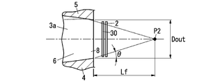
- the position P2 of the second focal point is, for example, as shown in FIG. 2, the straight line connecting the edge of the second opening (opening side opening) of the light guide 3 and the second focus and the central axis of the light guide 3 (
- the angle ⁇ with respect to the major axis of the reflecting surface 6 is determined to be 25 ° or less.
- ⁇ is given by tan ⁇ 1 ⁇ Dout / (2Lf) ⁇ .
- Lf is the distance between the second opening of the light guide 3 and the second focus position P2
- Dout is the diameter of the second opening of the light guide 3.
- the light receiving unit 2 is preferably arranged at a position as close to the second opening of the light guide 3 as possible. As the light receiving unit 2 is closer to the second opening of the light guide 3, it is possible to prevent light from leaking from the gap between the light receiving unit 2 and the second opening of the light guide 3.
- the distance between the light emitting unit 1 and the light receiving unit 2 is increased, the distance that the light from the light emitting unit 1 passes through the detection space 3a of the light guide 3 can be increased (the major axis of the reflecting surface 6 can be increased). Therefore, the amount of attenuation of light from the light emitting unit 1 can be increased. Therefore, the sensitivity can be improved.
- the minor axis of the reflecting surface 6 is constant, the diameter of the first opening of the light guide 3 decreases as the major axis of the reflecting surface 6 increases. Therefore, in order to sufficiently secure the amount of light (incident light quantity) entering the detection space 3a from the light emitting unit 1 through the first opening of the light guide 3, the minor diameter of the reflecting surface 6 must be increased, The light guide 3 becomes large.
- the distance between the light emitting unit 1 and the light receiving unit 2 be within a range of 10 to 150 mm.
- the position P2 of the second focal point is adjusted so that the amount of light incident on the surface (light receiving surface) of the light receiving unit 2 (light that has passed through the light guide 3) is uniformly distributed on the surface of the light receiving unit 2. It is desirable that In this case, even when the position of the light receiving unit 2 is shifted, a change in the amount of light incident on the light receiving unit 2 is reduced. Therefore, it is possible to prevent the performance from being varied for each product and the yield is improved, so that the production efficiency is increased.
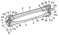
- the light guide 3 is made of, for example, a synthetic resin molded product having a cylindrical shape as a whole, and the light guide 3 passes through the central axis and is parallel to the central axis by the lower mirror 4 and the upper mirror 5. It is divided into two members.
- the joint surface of the lower mirror 4 and the upper mirror 5 is provided with a recess whose surface shape becomes an ellipsoid when the lower mirror 4 and the upper mirror 5 are joined.
- the reflective surface 6 is formed by coating the surface of these recesses with a metal having a high reflectivity (for example, chromium plating).
- recesses 4a and 5a recessed in a semicircular shape are provided at positions facing each other, and the lower mirror 4 and the upper mirror 5 are joined.
- the through-hole 7 is formed by the recesses 4a and 5a.
- the other end in the axial direction is provided with recesses 4b and 5b that are recessed in a semicircular shape at positions facing each other, and the lower mirror 4 and the upper mirror 5 are joined.
- the through hole 8 is formed by the recesses 4b and 5b.
- concave portions 4 c and 5 c that are recessed in a semicircular shape are provided in positions corresponding to the circumferential surface of the light guide 3 so as to face each other.
- the vent 9 is formed by the recesses 4c and 5c.
- a light emitting element 1a such as a light emitting diode that emits infrared light is disposed on the front surface of a disk-shaped base portion 1b, and a plurality of terminal pins 1c are provided on the rear surface of the base portion 1b.
- the light emitting unit 1 is attached to one end portion in the axial direction of the light guide 3 through a holding unit 10 including a cap unit 11 and a pressing plate 12.
- the cap part 11 is substantially disc-shaped, and a round hole-like recess 11a into which the end of the light guide 3 is inserted is provided on the end surface on the light guide 3 side, and the light guide is provided at the center of the bottom of the recess 11a.
- a round hole 11 b is provided so as to be continuous with the through hole 7 of the body 3.
- a concave portion 11c for accommodating the base portion 1a of the light emitting portion 1 is provided around the round hole 11b on the end surface of the cap portion 11 opposite to the light guide 3.
- the pressing plate 12 is substantially disc-shaped, and a through hole 12a through which the terminal pin 1c of the light emitting unit 1 is inserted is provided in the center.
- the inner diameter of the through hole 12a is set to be smaller than the outer diameter of the base portion 1b, and the outer diameter of the pressing plate 12 is set to be larger than the outer diameter of the base portion 1b.
- the light receiving unit 2 includes a CAN type main body 2b.
- a light receiving window 2c is opened in front of the main body 2b, and a light receiving element 2a (for example, made of a pyroelectric infrared detecting element) is accommodated inside the main body 2b so as to face the light receiving window 2c.
- a plurality of terminal pins 2d are provided on the rear surface of the main body 2b.
- the light receiving portion 2 is attached to the other end portion of the light guide 3 in the axial direction through a holding portion 20 including a cap portion 21 and a pressing plate 22.
- the cap part 21 is substantially disc-shaped, and a round hole-like recess 21a into which the end of the light guide 3 is inserted is provided on the end surface on the light guide 3 side, and the light guide is provided at the center of the bottom of the recess 21a.
- a round hole 21 b is provided so as to be continuous with the through hole 8 of the body 3.
- the pressing plate 22 is substantially disc-shaped, and a through hole 22a through which the terminal pin 2d of the light receiving unit 2 is inserted is provided in the center.
- the inner diameter of the through hole 22a is set to be smaller than the outer diameter of the main body 2b of the light receiving unit 2, and the outer diameter of the pressing plate 22 is set to be larger than the outer diameter of the main body 2b.
- the optical filter 30 is formed in a film shape and has a transmittance-wavelength characteristic such that the transmittance is reduced outside the wavelength range that is absorbed by the gas to be detected.
- the optical filter 30 is disposed on the front side of the light receiving unit 2, but may be provided integrally with the main body 2b of the light receiving unit 2 so as to be disposed on the front side of the light receiving element 2b.
- the operator overlaps the lower mirror 4 and the upper mirror 5 to form the light guide 3, and then the cap portion 11 is disposed on one end side of the light guide 3 in the axial direction (the end provided with the through hole 7). And the cap portion 21 is placed on the other axial end of the light guide 3 (the end provided with the through hole 8).
- the worker arranges the light emitting part 1 in the recess 11 c with the light emitting surface facing the light guide 3, and arranges the pressing plate 12 on the back side of the light emitting part 1.
- the holding screw 10 is screwed into the screw parts 4 d and 5 d of the light guide 3 through the mounting screws (not shown) passed through the holes 12 b and 11 d of the holding plate 12 and the cap part 11.
- the light emitting unit 1 is held between the holding unit 10 and the light guide 3.
- the operator arranges the light receiving unit 2 in the round hole 21b with the light receiving surface facing the light guide 3 side, and arranges the pressing plate 22 on the back side of the light receiving unit 2.
- the light emitting element 1 a faces the through hole 7, and the light receiving element 2 a is connected to the through hole 8.
- Opposing light emitted from the light emitting element 1a is applied to the internal space of the light guide 3 and directly enters the light receiving element 2a, or is reflected by the reflecting surface 6 and guided to the light receiving element 2a.
- the light emitting element 1a of the light emitting unit 1 irradiates light into the internal space of the light guide 3 when power is supplied to the detector A. Since the light emitting unit 1 is disposed at the focal position P1 of the ellipsoidal reflecting surface 6, when the light emitted from the light emitting unit 1 is reflected by the reflecting surface 6, the reflected light is reflected at the other focal position P2. Focused.
- the light receiving unit 2 Since the light receiving unit 2 is arranged on the straight line connecting the focal positions P1 and P2 and closer to the light emitting unit 1 than the focal position P2, the reflected light reflected by the reflecting surface 6 passes through the optical filter 30. A signal (current signal or voltage signal) having a magnitude corresponding to the amount of light received is output from the light receiving unit 2.
- the gas to be detected is introduced into the internal space of the light guide 3 through the vent 9 and the concentration of the gas to be detected increases in the internal space, the light absorbed by the gas increases, The amount of light incident on the portion 2 is reduced.
- the amount of light incident on the light receiving unit 2 decreases, the magnitude of the signal output from the light receiving unit 2 also changes. Therefore, based on the output signal from the light receiving unit 2, the presence / absence of the detection target gas and its concentration are detected. be able to.
- FIG. 9 shows an example of measurement of the change in the concentration of the gas to be detected and the temporal change in the amount of incident light on the light receiving unit 2, where line D is the concentration of gas and line E is the amount of incident light on the light receiving unit 2.
- the amount of incident light decreases as the value increases, and the amount of incident light increases as the concentration decreases.
- the reflecting surface 6 is formed in an ellipsoidal shape
- the light emitting unit 1 is disposed at one focal position P1 of the reflecting surface 6, and the light is emitted with respect to the other focal position P2.
- the light receiving unit 2 is disposed on the side close to the unit 1.
- the light emitting unit 1 Since the light emitting unit 1 is disposed at one focal position P1 of the reflecting surface 6, the radiated light from the light emitting unit 1 is reflected by the reflecting surface 6 and condensed at the other focal position P2.
- the light receiving unit 2 Since the light receiving unit 2 is disposed on the side closer to the light emitting unit 1 with respect to the other focal position P2, the light receiving unit 2 is compared with the case where the light receiving unit 2 is disposed at the focal position P2 as shown in FIG. The incident angle of light incident on can be reduced (see FIG. 2).
- the wavelength range of light to be absorbed differs depending on the type of gas, and the absorption wavelength range varies depending on the gas to be detected.
- An optical filter 30 having a transmittance (absorption wavelength region) higher than that of the other wavelength regions is arranged on the front side of the light receiving unit 2.
- FIG. 7 shows an optical path of light that passes through the optical filter 30 and enters the light receiving unit 2.
- the optical path length through which the light passes through the filter is different from that in the case where the light L1 is incident from a direction substantially orthogonal to the optical filter 30. As a result, the transmission characteristics change.
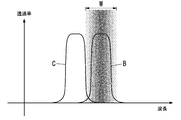
- FIG. 8 shows the transmittance-wavelength characteristics of the optical filter 30 and is adjusted to the transmittance-wavelength characteristics B such that the transmittance decreases outside the absorption wavelength range of the gas to be detected.
- the transmittance-wavelength characteristic of the optical filter 30 becomes a characteristic as indicated by the line B, and attenuates light outside the absorption wavelength range. be able to.
- the optical path length passing through the filter becomes long, so that the transmittance peak shifts to the short wavelength side, and the transmittance-wavelength characteristics are linear. It becomes a characteristic as shown by C.
- the transmittance in the absorption wavelength region of the gas to be detected is low, and the transmittance is high on the shorter wavelength side than the absorption wavelength region. Since the light is transmitted, the S / N ratio may be reduced.
- the light receiving unit 2 is arranged on a straight line connecting the focal positions P1 and P2 and closer to the light emitting unit 1 with respect to the focal position P2, the light incident on the optical filter 30 The incident angle can be reduced. Therefore, the deviation of the transmittance-wavelength characteristic from the absorption wavelength region of the gas to be detected is reduced, and a desired transmittance-wavelength characteristic is obtained. It can be detected reliably.
- Optical filters 30 having different transmission wavelength bands may be arranged on the front side of the respective light receiving units 2A, 2B.
- the first modification of the detector A of the present embodiment includes a plurality of light receiving units 2.
- the reflecting surface 6 is a concave ellipsoid whose major axis is a straight line connecting the centers of the plurality of light receiving portions 2 (2A, 2B) and the light emitting portion 1.
- the centers of the plurality of light receiving units 2 (2A, 2B) are the light receiving units 2A, 2A, 2B in the direction (vertical direction in FIG. 10) orthogonal to the axial direction of the light guide 3 (horizontal direction in FIG. 10). The midpoint of 2B.
- the first modification of the detector A of the present embodiment includes a plurality of optical filters 30 (31, 32) corresponding to the plurality of light receiving units 2 (2A, 2B), and a detection unit 40, respectively.
- Each of the plurality of optical filters 30 is disposed between the corresponding light receiving unit 20 and the light emitting unit 1.
- Each of the plurality of light receiving units 20 is configured to provide an output corresponding to the amount of received light to the detection unit 40.
- the detection unit 40 is configured to determine the state of a predetermined gas based on the output received from the light receiving unit 20.
- the outputs of the light receiving units 2A and 2B are input to the calculation unit 40 (detection unit) formed of, for example, a microcomputer.
- the calculation unit 40 detects the state of the gas to be detected based on the amount of light received by the plurality of light receiving units 2A and 2B.
- the state of the detection target gas detected by the calculation unit (detection unit) 40 is the presence or concentration of the detection target gas in the internal space, or the internal space when there are a plurality of detection target gases. Such as the type of gas present.
- the light emitting unit 1 is disposed at one focal position P1 of the reflecting surface 6.
- the light receiving portions 2A and 2B are disposed closer to the light emitting portion 1 than the other focal position P2 of the reflecting surface 6, and are disposed between the through hole 8 of the light guide 3 and the focal position P2.
- the optical filter 31 is disposed on the front side of the light receiving unit 2A, and the optical filter 32 is disposed on the front side of the light receiving unit 2B.
- the optical filter 31 is a detection optical bandpass filter that transmits light in a wavelength band substantially the same as the absorption wavelength of the gas to be detected.
- the optical filter 32 is a reference optical bandpass filter that transmits light in a wavelength band different from that of the optical filter 31. That is, in the first modification of the detector A of the present embodiment, the plurality of optical filters 30 (31, 32) have different transmission wavelength bands.
- the calculation unit 40 obtains the difference between the received light amount of the light receiving unit 2A obtained from the output of the light receiving unit 2A and the received light amount of the light receiving unit 2B obtained from the output of the light receiving unit 2B, thereby detecting the gas to be detected. Detects the presence or absence and concentration.
- the calculation unit 40 obtains the difference between the amount of light received by the light receiving unit 2A and the amount of light received by the light receiving unit 2B, thereby responding to the concentration of the gas to be detected. An output can be obtained, and it is possible to detect that the gas to be detected has flowed in and its concentration.
- the light receiving units 2A and 2B Since both outputs decrease, the difference between the received light amount of the light receiving unit 2A and the received light amount of the light receiving unit 2B does not change. Therefore, it is possible to reduce the possibility that the calculation unit 40 erroneously detects a decrease in the light emission amount due to causes other than gas absorption as light absorption by the detection target gas.
- optical filters 31 and 32 may be optical bandpass filters for detection that transmit light in a wavelength band that is approximately the same as the absorption wavelength of each separate gas, and two types of gas states may be detected.
- the calculation unit 40 detects the presence of the gas A1 and its concentration based on the output of the light receiving unit 2A.
- a gas whose pass band of the optical filter 32 is an absorption wavelength region (hereinafter referred to as a gas A2) flows into the inner space of the light guide 3, the amount of received light 2B varies depending on the concentration of the gas A2. Since it falls, the calculating part 40 detects that gas A2 exists and its density
- the computing unit 40 causes a plurality of types of gas states. Can be detected.
- the plurality of optical filters 30 may have the same transmission wavelength band.
- the calculation unit 40 can obtain an output according to the concentration of the gas to be detected by obtaining an average of the light reception amount of the light receiving unit 2A and the light reception amount of the light receiving unit 2B. It is possible to detect the inflow of gas and its concentration.
- two sets of the light receiving unit 2 and the optical filter 30 are arranged on the side closer to the light emitting unit 1 than the focal position P2, but three or more sets of the light receiving unit 2 and the optical filter 30 are arranged. May be.
- one set of them is used as a reference, and an optical bandpass filter whose transmission wavelength band is set to a wavelength band different from the absorption wavelength band to be detected is used as the optical filter 30, and the remaining plural sets are detected. If it uses, the state of multiple types of gas can be detected, without misdetecting the fall of the light-receiving amount by causes other than gas absorption.
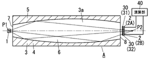
- the reflecting surface 6 is formed in one ellipsoidal shape, but as shown in the second modification of the detector A of the present embodiment in FIG. 11, the light guide 3 Ellipsoidal reflecting surfaces 6A and 6B having a point P1 where the light emitting unit 1 is disposed as one of the focal points may be provided on the inner surface (the inner surface of the detection space 3a).
- the light guide 3 includes a plurality of reflection surfaces 6.
- the plurality of reflecting surfaces 6 (6A, 6B) are respectively associated with the plurality of light receiving units 2 (2A, 2B).
- the reflecting surface 6A is one surface (upper surface in FIG. 11) in the direction (vertical direction in FIG. 11) orthogonal to the axial direction of the light guide 3 among the inner surfaces of the detection space 3a.
- the reflecting surface 6B is the other surface (the lower surface in FIG. 11) in the direction (vertical direction in FIG. 11) orthogonal to the axial direction of the light guide 3 among the inner surfaces of the detection space 3a.
- Each of the plurality of reflecting surfaces 6 (6A, 6B) is a concave elliptical surface having a straight line connecting the associated light receiving portion 2 and light emitting portion 1 as a major axis.
- the reflective surface 6A is a concave ellipsoid whose major axis is a straight line L3 connecting the associated light receiving portion 2A and the light emitting portion 1.
- 6 A of reflective surfaces have a focus (1st focus) in the position of the light emission part 1, and have a 2nd focus on the opposite side to a 1st focus with respect to the light-receiving part 2A matched.
- the position of the first focus of the reflecting surface 6A is indicated by the focus position P1
- the position of the second focus is indicated by the focus position P3.
- the reflective surface 6B is a concave ellipsoid whose major axis is a straight line L4 connecting the associated light receiving unit 2B and the light emitting unit 1.
- the reflecting surface 6B has a focal point (first focal point) at the position of the light emitting unit 1, and has a second focal point opposite to the first focal point with respect to the associated light receiving unit 2B.
- the position of the first focus of the reflecting surface 6A is indicated by the focus position P1
- the position of the second focus is indicated by the focus position P4.
- the plurality of reflecting surfaces 6 (6A, 6B) have the same first focal point, but have different second focal points.
- the light receiving unit 2A is disposed on the straight line L3 connecting the focal points P1 and P3 of the reflecting surface 6A on the side closer to the light emitting unit 1 with respect to the focal point P3, and on the front side of the light receiving unit 2A.
- An optical filter 31 is disposed.
- the light receiving unit 2B is arranged on the straight line L4 connecting the focal points P1 and P4 of the reflecting surface 6B on the side closer to the light emitting unit 1 with respect to the focal point P4, and the optical filter 32 is arranged on the front side of the light receiving unit 2B.
- the light guide 3 may include three or more reflecting surfaces 6.
- the reflective surface 6A provided in the recessed part inner surface of the upper mirror 5 and the reflective surface 6B provided in the recessed part inner surface of the lower mirror 4 are included. Near the boundary (portion 3b connecting the plurality of reflecting surfaces 6 (6A, 6B)), a vent hole 9 for allowing gas to flow into the internal space is provided.
- the light guide 3 includes a vent 9 for moving a predetermined gas between the detection space 3a and the external space.
- the ventilation hole 9 is formed in the site
- the boundary portion between the reflecting surface 6A and the reflecting surface 6B (the portion 3b connecting the plurality of reflecting surfaces 6A and 6B) is not a perfect ellipsoid, the light emitting unit 1 is near the boundary between the reflecting surfaces 6A and 6B. Is reflected on the focal points P3 and P4, it is difficult to enter the light receiving portions 2A and 2B.
- gas can be introduced into the internal space of the light guide 3 without affecting the amount of light incident on the light receiving portions 2A and 2B, Gas can flow out from the space to the outside.
- the detector A shown in FIGS. 11 to 12 includes two light receiving units 2 and two optical filters 30 (a set of the light receiving unit 2A and the optical filter 31 and a set of the light receiving unit 2B and the optical filter 32). Three or more sets of the light receiving unit 2 and the optical filter 30 may be provided.
- the detector A of the present embodiment includes the light emitting unit 1, the light receiving unit 2, and the light guide 3.
- the light guide 3 has an internal space into which a gas to be detected is introduced, and guides the emitted light to the light receiving unit 2 by reflecting the emitted light from the light emitting unit 1 on the reflection surface 6 around the internal space. Shine.
- the shape of the reflecting surface 6 is formed in an ellipsoidal shape having two points P1 and P2 as focal points.
- the light emitting unit 1 is disposed at the position of one focal point P1, and the light receiving unit 2 is disposed on the side closer to the light emitting unit 1 with respect to the position of the other focal point P2.
- the detector A of the present embodiment shown in FIG. 1 has a light emitting unit 1, a light receiving unit 2, and a detection space 3 a for determining a predetermined gas state, and is emitted from the light emitting unit 1. And a light guide 3 that guides light to the light receiving unit 2 through the detection space 3a.
- the light guide 3 has a reflection surface 6 that reflects the light emitted from the light emitting unit 1 on the inner surface of the detection space 3a.
- the reflecting surface 6 is a concave ellipsoid whose major axis is a straight line defined by the light receiving unit 2 and the light emitting unit 1.
- the reflecting surface 6 has a focal point (first focal point) at the position of the light emitting unit 1, and has a second focal point opposite to the first focal point with respect to the light receiving unit 2.
- the light emission part 1 is arrange
- the reflection surface 6 is formed so that the focal position P2 is located on the far side from the light receiving unit 2 with respect to the light emitting unit 1. Therefore, the angle of light incident on the light receiving unit 2 can be reduced.
- the light receiving unit 2 is disposed on the side closer to the light emitting unit 1 with respect to the other focal position P2, the light incident on the light receiving unit 2 compared to the case where the light receiving unit 2 is disposed at the focal position P2.
- the incident angle can be reduced.
- the light-receiving part 2 The type and state (for example, concentration) of the gas flowing into the internal space from the output can be detected.
- the optical filter 30 that attenuates light outside the absorption wavelength range of the gas to be detected is disposed on the front side of the light receiving unit 2, the incident angle of the light incident on the optical filter 30 can be reduced.
- the incident angle to the optical filter 30 When the incident angle to the optical filter 30 is increased, the optical path length passing through the filter is increased, thereby reducing the transmittance and changing the transmission wavelength band to increase unnecessary light.
- the deviation of the transmittance-wavelength characteristic from the absorption wavelength region of the gas to be detected is reduced, and the gas to be detected can be reliably detected.
- the light emitting unit 1 is disposed at one focal position P1 of the reflecting surface 6, and light is received on the side closer to the light emitting unit 1 with respect to the other focal position P2. Since the part 2 is disposed, the incident angle of the light reflected by the reflecting surface 6 and incident on the light receiving part 2 can be reduced.
- a plurality of light receiving units 2 are provided, optical filters 30 having different transmission wavelength bands are arranged on the front side of each light receiving unit 2, and based on the amount of light received by the plurality of light receiving units 2. It is also preferable to include a detection unit 40 that detects the state of the gas to be detected.
- the reflecting surface 6 is a concave ellipsoid whose major axis is a straight line connecting the centers of the plurality of light receiving portions 2 (2A, 2B) and the light emitting portion 1.
- the 1st modification of the detector A of this embodiment is provided with the some optical filter 30 (31, 32) each corresponding to the some light-receiving part 2 (2A, 2B), and the detection part 40.
- Each of the plurality of optical filters 30 is disposed between the corresponding light receiving unit 20 and the light emitting unit 1.
- Each of the plurality of light receiving units 20 is configured to provide an output corresponding to the amount of received light to the detection unit 40.
- the detection unit 40 is configured to determine the state of a predetermined gas based on the output received from the light receiving unit 20.
- the amount of light received by the light receiving unit 2 fluctuates due to a cause other than gas absorption (for example, variation in applied voltage to the light emitting unit 1, deterioration of the light emitting unit 1, dirt on the reflecting surface 6, etc.)
- a plurality of light receiving units Since the amount of received light changes in the same way in FIG. 2, a decrease in the amount of received light due to causes other than gas absorption may be erroneously detected as inflow of gas into the internal space by detecting the outputs of the plurality of light receiving units 2. Can be reduced.
- the incident angle to the optical filter 30 when the incident angle to the optical filter 30 is increased, unnecessary light increases because the transmission wavelength band of the optical bandpass filter is changed. However, since the incident angle to the optical filter 30 can be reduced, the transmission through the optical filter 30 is increased. The deviation of the rate-wavelength characteristic is reduced, and the gas to be detected can be reliably detected.
- the incident angle of light incident on the optical filter 30 (that is, the angle between the incident direction of light on the optical filter 30 and the optical axis of the optical filter) can be reduced. Therefore, the optical filter 30 can exhibit correct transmittance-wavelength characteristics, and the S / N ratio can be improved. In addition, reflection of light (infrared rays) on the surface of the optical filter can be reduced.
- the plurality of optical filters 30 (31, 32) have different transmission wavelength bands.
- the plurality of optical filters 30 (31, 32) may have the same transmission wavelength band.
- the reflecting surface 6 connects the light receiving units 2 (2A, 2B) and the light emitting units 1 respectively. It is also preferable to include a plurality of reflecting surfaces 6 (6A, 6B) formed in an ellipsoidal shape with the connecting straight lines (L3, L4) as the central axis.
- a second modification of the detector A of the present embodiment shown in FIG. 11 includes a plurality of light receiving units 2 in the detector A of the first embodiment shown in FIG.
- the light guide 3 includes a plurality of reflection surfaces 6.
- the plurality of reflecting surfaces 6 (6A, 6B) are respectively associated with the plurality of light receiving units 2 (2A, 2B).
- Each of the plurality of reflecting surfaces 6 is a concave ellipsoid whose major axis is a straight line connecting the associated light receiving unit 2 and light emitting unit 1.
- Each of the plurality of reflecting surfaces 6 has a focal point (first focal point) at the position of the light emitting unit 1, and has a second focal point opposite to the first focal point with respect to the associated light receiving unit 2.
- the second modified example of the detector A of the present embodiment shown in FIG. 11 includes a light emitting unit 1, a plurality of light receiving units 2 (2A, 2B), and a detection space 3a for determining a predetermined gas state. And a light guide 3 that guides light emitted from the light emitting unit 1 to the plurality of light receiving units 2 (2A, 2B) through the detection space 3a.
- the light guide 3 has a plurality of reflecting surfaces 6 (6A, 6B) that reflect the light emitted from the light emitting unit 1 on the inner surface of the detection space 3a.
- the plurality of reflecting surfaces 6 (6A, 6B) are respectively associated with the plurality of light receiving units 2 (2A, 2B).
- Each of the plurality of reflecting surfaces 6 is a concave ellipsoid whose major axis is a straight line connecting the associated light receiving unit 2 and light emitting unit 1.
- Each of the plurality of reflecting surfaces 6 has a focal point (first focal point) at the position of the light emitting unit 1, and has a second focal point opposite to the first focal point with respect to the associated light receiving unit 2.
- each of the plurality of reflecting surfaces 6 has a second focus on the opposite side of the first focus with respect to the associated light receiving unit 2.
- Each of the plurality of reflecting surfaces 6 may have a second focal point at the position of the associated light receiving unit 2.
- the second modification of the detector A of the present embodiment includes a plurality of optical filters 30 (31, 32) corresponding to the plurality of light receiving units 2 (2A, 2B) and a detection unit 40, respectively.
- Each of the plurality of optical filters 30 is disposed between the corresponding light receiving unit 20 and the light emitting unit 1.
- Each of the plurality of light receiving units 20 is configured to provide an output corresponding to the amount of received light to the detection unit 40.
- the detection unit 40 is configured to determine the state of a predetermined gas based on the output received from the light receiving unit 20.
- the plurality of optical filters 30 (31, 32) have different transmission wavelength bands.
- the plurality of optical filters 30 (31, 32) may have the same transmission wavelength band.
- a vent 9 for allowing gas to enter and exit the internal space 3a is provided in the vicinity of the boundaries of the plurality of reflecting surfaces 6.
- the light guide 3 moves a predetermined gas between the detection space 3a and the external space. Vents 9 are provided.
- the vent 9 is formed in a portion 3b that connects the plurality of reflecting surfaces 6 together.
- gas can flow into the internal space 3a of the light guide 3, A gas can flow out from the internal space 3a to the outside.
Abstract
This detector is provided with a light emitting section, a light receiving section, and a light guide body which has a detection space for specifying the state of a predetermined gas and which conducts light emitted from the light emitting section to the light receiving section through the detection space. The light guide body has, on the inner surface of the detection space, a reflection surface for reflecting the light emitted from the light emitting section. The reflection surface is an elliptical concave surface, the major axis of which being a straight line defined by both the light emitting section and the light receiving section. The reflection surface has a first focal point at the position of the light emitting section and has a second focal point located on the opposite side of the light receiving section from the first focal point.
Description
本発明は、検出器に関し、特に気体の種類や濃度、煙の濃度、或いは気体に含まれる塵埃などを検出するための検出器に関するものである。
The present invention relates to a detector, and more particularly to a detector for detecting the type and concentration of gas, the concentration of smoke, dust contained in the gas, and the like.
従来、内壁の形状が回転楕円体に形成されたガス計測室を備え、ガス計測室内で一方の焦点に赤外線放射源を、他方の焦点に赤外線を検出する検出器を配置したガスセンサがあった(例えば文献1[日本国公開特許公報第2007-147613号]参照)。
2. Description of the Related Art Conventionally, there has been a gas sensor that includes a gas measurement chamber having an inner wall formed in a spheroid, and in which an infrared radiation source is disposed at one focal point and a detector that detects infrared rays is disposed at the other focal point ( For example, see Document 1 [Japanese Published Patent Publication No. 2007-147613].
ガス計測室に検出対象の気体が存在すると、気体の種類に応じて特定の波長の赤外線が吸収されるから、検出器によって検出される赤外線の強度をもとに、ガス計測室に存在する気体の組成を検出できる。
If there is a gas to be detected in the gas measurement chamber, infrared light of a specific wavelength is absorbed according to the type of gas, so the gas present in the gas measurement chamber is based on the intensity of infrared light detected by the detector. Can be detected.
尚、文献2(日本国公開特許公報第2006-275980号)にも、楕円体形状のガス室を備え、ガス室内で一方の焦点に赤外線発光装置が配置され、他方の焦点に赤外線検出装置が配置された赤外線式ガス検出器が開示されている。
Reference 2 (Japanese Published Patent Application No. 2006-275980) also includes an ellipsoidal gas chamber, in which an infrared light emitting device is disposed at one focal point, and an infrared detecting device is disposed at the other focal point. An arranged infrared gas detector is disclosed.
上述した文献1のガスセンサや文献2の検出器では、受光素子が焦点位置に配置されているので、回転楕円体の表面で反射した光を受光素子に集光させることができる。
In the gas sensor of Reference 1 and the detector of Reference 2 described above, since the light receiving element is disposed at the focal position, the light reflected by the surface of the spheroid can be condensed on the light receiving element.
しかしながら、受光素子付近の回転楕円体の表面で1回反射されて受光素子に入射する光(赤外線)は、その入射角度が大きくなっていた。
However, the incident angle of light (infrared rays) that is reflected once on the surface of the spheroid near the light receiving element and incident on the light receiving element is large.
特に、上記のような検出器では、受光素子の前方に光学フィルタが配置される。受光素子に入射する光の入射角度が大きくなると、光学フィルタに入射する光の入射角度(すなわち、光学フィルタへの光の入射方向と光学フィルタの光軸との間の角度)も大きくなる。そして、光学フィルタへの入射角度が大きい光に対しては、光学フィルタは正しい透過率-波長特性を発揮できない場合があり、結果としてS/N比が悪くなるおそれがある。また、光学フィルタの表面での光の反射が増えてしまう。
In particular, in the detector as described above, an optical filter is disposed in front of the light receiving element. As the incident angle of light incident on the light receiving element increases, the incident angle of light incident on the optical filter (that is, the angle between the incident direction of light on the optical filter and the optical axis of the optical filter) also increases. For light having a large incident angle to the optical filter, the optical filter may not exhibit correct transmittance-wavelength characteristics, and as a result, the S / N ratio may be deteriorated. In addition, the reflection of light on the surface of the optical filter increases.
本発明は上記課題に鑑みて為されたものであり、その目的とするところは、受光部への光の入射角度を小さくした検出器を提供することにある。
The present invention has been made in view of the above problems, and an object of the present invention is to provide a detector in which the incident angle of light to the light receiving unit is reduced.
本発明に係る第1の形態の検出器は、発光部と、受光部と、所定の気体の状態を判定するための検出空間を有し前記発光部から放射された光を前記検出空間を通して前記受光部へ導く導光体と、を備える。前記導光体は、前記検出空間の内面に、前記発光部から放射された光を反射する反射面を有する。前記反射面は、前記発光部と前記受光部とで定義される直線を長軸とする凹楕円面である。前記反射面は、前記発光部の位置に第1焦点を有し、かつ、前記受光部に対して前記第1焦点と反対側に第2焦点を有する。
The detector of the 1st form which concerns on this invention has a detection space for judging the state of predetermined | prescribed gas which has a light emission part, a light-receiving part, and the light radiated | emitted from the said light emission part through the said detection space. A light guide led to the light receiving unit. The light guide has a reflection surface that reflects light emitted from the light emitting unit on an inner surface of the detection space. The reflection surface is a concave elliptical surface having a straight line defined by the light emitting portion and the light receiving portion as a major axis. The reflective surface has a first focal point at the position of the light emitting unit, and a second focal point on the opposite side of the first focal point with respect to the light receiving unit.
本発明に係る第2の形態の検出器は、第1の形態において、前記受光部を複数備える。前記反射面は、前記複数の受光部の中心と前記発光部とを結ぶ直線を長軸とする凹楕円面である。
The detector of the 2nd form which concerns on this invention is equipped with multiple said light-receiving parts in a 1st form. The reflecting surface is a concave ellipsoid having a long axis as a straight line connecting the centers of the plurality of light receiving portions and the light emitting portion.
本発明に係る第3の形態の検出器は、第1の形態において、前記受光部を複数備える。前記導光体は、前記反射面を複数備える。前記複数の反射面は、前記複数の受光部に、それぞれ対応付けられる。前記複数の反射面の各々は、前記対応付けられた受光部と前記発光部とを結ぶ直線を長軸とする凹楕円面である。前記複数の反射面の各々は、前記発光部の位置に前記第1焦点を有し、かつ、前記対応付けられた受光部に対して前記第1焦点と反対側に前記第2焦点を有する。
The detector of the 3rd form which concerns on this invention is equipped with multiple said light-receiving parts in a 1st form. The light guide includes a plurality of the reflection surfaces. The plurality of reflecting surfaces are respectively associated with the plurality of light receiving units. Each of the plurality of reflecting surfaces is a concave ellipsoid having a long axis as a straight line connecting the associated light receiving portion and the light emitting portion. Each of the plurality of reflecting surfaces has the first focal point at the position of the light emitting unit, and has the second focal point on the opposite side of the first focal point with respect to the associated light receiving unit.
本発明に係る第4の形態の検出器では、第3の形態において、前記導光体は、前記検出空間と外部空間との間で前記所定の気体が移動するための通気口を備える。前記通気口は、前記複数の反射面間を連結する部位に形成される。
In the detector according to the fourth aspect of the present invention, in the third aspect, the light guide includes a vent for the predetermined gas to move between the detection space and the external space. The vent is formed at a portion connecting the plurality of reflecting surfaces.
本発明に係る第5の形態の検出器は、第2~第4のいずれかの形態において、前記複数の受光部にそれぞれ対応する複数の光学フィルタと、検出部と、を備える。前記複数の光学フィルタの各々は、前記対応する受光部と前記発光部との間に配置される。前記複数の受光部の各々は、受けた光の量に応じた出力を前記検出部に与えるように構成される。前記検出部は、前記受光部から受け取った出力に基づいて前記所定の気体の状態を判定するように構成される。
A detector according to a fifth aspect of the present invention according to any one of the second to fourth aspects includes a plurality of optical filters respectively corresponding to the plurality of light receiving units, and a detection unit. Each of the plurality of optical filters is disposed between the corresponding light receiving unit and the light emitting unit. Each of the plurality of light receiving units is configured to give an output corresponding to the amount of received light to the detection unit. The detection unit is configured to determine a state of the predetermined gas based on an output received from the light receiving unit.
本発明に係る第6の形態の検出器では、第5の形態において、前記複数の光学フィルタは、異なる透過波長帯域を有する。
In the detector according to the sixth aspect of the present invention, in the fifth aspect, the plurality of optical filters have different transmission wavelength bands.
本発明に係る第7の形態の検出器では、第5の形態において、前記複数の光学フィルタは、同じ透過波長帯域を有する。
In the detector according to the seventh aspect of the present invention, in the fifth aspect, the plurality of optical filters have the same transmission wavelength band.
本発明に係る第8の形態の検出器は、発光部と、複数の受光部と、所定の気体の状態を判定するための検出空間を有し前記発光部から放射された光を前記検出空間を通して前記複数の受光部へ導く導光体と、を備える。前記導光体は、前記検出空間の内面に、前記発光部から放射された光を反射する複数の反射面を有する。前記複数の反射面は、前記複数の受光部に、それぞれ対応付けられる。前記複数の反射面の各々は、前記対応付けられた受光部と前記発光部とを結ぶ直線を長軸とする凹楕円面である。前記複数の反射面の各々は、前記発光部の位置に第1焦点を有する。
The detector of the 8th form which concerns on this invention has a detection space for judging the state of predetermined | prescribed gas, the light emission part, several light-receiving part, and the light radiated | emitted from the said light emission part is said detection space. And a light guide that leads to the plurality of light receiving parts. The light guide has a plurality of reflection surfaces that reflect light emitted from the light emitting unit on the inner surface of the detection space. The plurality of reflecting surfaces are respectively associated with the plurality of light receiving units. Each of the plurality of reflecting surfaces is a concave ellipsoid having a long axis as a straight line connecting the associated light receiving portion and the light emitting portion. Each of the plurality of reflecting surfaces has a first focal point at the position of the light emitting unit.
本発明に係る第9の形態の検出器では、第8の形態において、前記複数の反射面の各々は、前記対応付けられた受光部に対して前記第1焦点と反対側に第2焦点を有する。
According to a ninth aspect of the detector of the present invention, in the eighth aspect, each of the plurality of reflecting surfaces has a second focal point opposite to the first focal point with respect to the associated light receiving unit. Have.
本発明に係る第10の形態の検出器では、第8の形態において、前記複数の反射面の各々は、前記対応付けられた受光部の位置に第2焦点を有する。
In the detector according to the tenth aspect of the present invention, in the eighth aspect, each of the plurality of reflection surfaces has a second focal point at the position of the associated light receiving unit.
本発明に係る第11の形態の検出器では、第8~第10のいずれかの形態において、前記導光体は、前記検出空間と外部空間との間で前記所定の気体が移動するための通気口を備える。前記通気口は、前記複数の反射面間を連結する部位に形成される。
In the detector of the eleventh aspect according to the present invention, in any of the eighth to tenth aspects, the light guide is configured to move the predetermined gas between the detection space and an external space. Provide vents. The vent is formed at a portion connecting the plurality of reflecting surfaces.
本発明に係る第12の形態の検出器は、第8~第11のいずれかの形態において、前記複数の受光部にそれぞれ対応する複数の光学フィルタと、検出部と、を備える。前記複数の光学フィルタの各々は、前記対応する受光部と前記発光部との間に配置される。前記複数の受光部の各々は、受けた光の量に応じた出力を前記検出部に与えるように構成される。前記検出部は、前記受光部から受け取った出力に基づいて前記所定の気体の状態を判定するように構成される。
A detector according to a twelfth aspect of the present invention includes, in any of the eighth to eleventh aspects, a plurality of optical filters corresponding to the plurality of light receiving units, and a detection unit. Each of the plurality of optical filters is disposed between the corresponding light receiving unit and the light emitting unit. Each of the plurality of light receiving units is configured to give an output corresponding to the amount of received light to the detection unit. The detection unit is configured to determine a state of the predetermined gas based on an output received from the light receiving unit.
本発明に係る第13の形態の検出器では、第12の形態において、前記複数の光学フィルタは、異なる透過波長帯域を有する。
In the detector of the thirteenth aspect according to the present invention, in the twelfth aspect, the plurality of optical filters have different transmission wavelength bands.
本発明に係る第14の形態の検出器では、第12の形態において、前記複数の光学フィルタは、同じ透過波長帯域を有する。
In the detector according to the fourteenth aspect of the present invention, in the twelfth aspect, the plurality of optical filters have the same transmission wavelength band.
以下、本発明に係る検出器の実施形態を図1~図12に基づいて説明する。
Hereinafter, embodiments of the detector according to the present invention will be described with reference to FIGS.
本実施形態の検出器Aは、検出対象の気体(例えば一酸化炭素やメタンなど)の種類及び濃度を検出するために用いられる。尚、検出器Aは気体の種類や濃度を検出するものに限定されるものではなく、煙や塵埃の有無やその濃度を検出するものでもよい。
The detector A of this embodiment is used to detect the type and concentration of a gas to be detected (for example, carbon monoxide, methane, etc.). The detector A is not limited to detecting the type and concentration of gas, and may be a detector that detects the presence or concentration of smoke or dust.
この検出器Aは、図1,2,4-6に示すように、発光部1と、受光部2と、円柱状の導光体3(下部ミラー4及び上部ミラー5からなる)と、発光部1を保持する保持部10と、受光部2を保持する保持部20と、光学フィルタ30を備えている。
1, 2, 4-6, the detector A includes a light emitting unit 1, a light receiving unit 2, a cylindrical light guide 3 (consisting of a lower mirror 4 and an upper mirror 5), and a light emission. A holding unit 10 that holds the unit 1, a holding unit 20 that holds the light receiving unit 2, and an optical filter 30 are provided.
導光体3は、所定の気体の状態を判定するための検出空間(内部空間)3aを有する。導光体3は、発光部1から放射された光を検出空間3aを通して受光部2へ導くように構成される。導光体3は、検出空間3aの内面に、発光部1から放射された光を反射する反射面6を有する。
The light guide 3 has a detection space (internal space) 3a for determining a predetermined gas state. The light guide 3 is configured to guide the light emitted from the light emitting unit 1 to the light receiving unit 2 through the detection space 3a. The light guide 3 has a reflection surface 6 that reflects the light emitted from the light emitting unit 1 on the inner surface of the detection space 3a.
反射面6は、発光部1と受光部2とで定義される直線(図1に示す例では、発光部1の中心と受光部2の中心とを結ぶ直線)L0を長軸とする凹楕円面である。反射面6は、発光部1の位置に焦点(第1焦点)を有し、かつ、受光部2に対して焦点(第1焦点)と反対側に焦点(第2焦点)を有する。図1,2では、反射面6の第1焦点の位置が焦点位置P1で示され、第2焦点の位置が焦点位置P2で示されている。
The reflecting surface 6 is a concave ellipse whose major axis is a straight line defined by the light emitting unit 1 and the light receiving unit 2 (in the example shown in FIG. 1, a straight line connecting the center of the light emitting unit 1 and the center of the light receiving unit 2) L0. Surface. The reflecting surface 6 has a focal point (first focal point) at the position of the light emitting unit 1 and has a focal point (second focal point) on the opposite side of the focal point (first focal point) with respect to the light receiving unit 2. 1 and 2, the position of the first focal point of the reflecting surface 6 is indicated by a focal point position P1, and the position of the second focal point is indicated by a focal point point P2.
導光体3は、筒状(本実施形態では円筒状)に形成されている。導光体3は、第1焦点に近い開口(第1開口)と、第2焦点に近い開口(第2開口)と、を有する。導光体3は、第1開口から導光体3の内部に入った光を、第2開口から導光体3の外部に導くように構成される。
The light guide 3 is formed in a cylindrical shape (cylindrical in this embodiment). The light guide 3 has an opening close to the first focal point (first opening) and an opening close to the second focal point (second opening). The light guide 3 is configured to guide light that has entered the light guide 3 through the first opening to the outside of the light guide 3 through the second opening.
なお、反射面6の第1焦点の位置(焦点位置)P1は発光部1の位置と厳密な意味で一致している必要は無く、実質的に一致しているとみなせればよい。
Note that the position (focal position) P1 of the first focal point of the reflecting surface 6 does not need to coincide with the position of the light emitting unit 1 in a strict sense, and may be regarded as substantially coincident.
第2焦点の位置P2は、たとえば、図2に示すように、導光体3の第2開口(出口側の開口)の縁と第2焦点とを結ぶ直線と導光体3の中心軸(反射面6の長軸)との角度θが25°以下となるように決定される。ここで、θは、tan-1{Dout/(2Lf)}で与えられる。Lfは導光体3の第2開口と第2の焦点の位置P2との距離であり、Doutは導光体3の第2開口の直径である。
The position P2 of the second focal point is, for example, as shown in FIG. 2, the straight line connecting the edge of the second opening (opening side opening) of the light guide 3 and the second focus and the central axis of the light guide 3 ( The angle θ with respect to the major axis of the reflecting surface 6 is determined to be 25 ° or less. Here, θ is given by tan −1 {Dout / (2Lf)}. Lf is the distance between the second opening of the light guide 3 and the second focus position P2, and Dout is the diameter of the second opening of the light guide 3.
受光部2は、可能な限り、導光体3の第2開口に近い位置に配置されることが好ましい。受光部2が導光体3の第2開口に近いほど、受光部2と導光体3の第2開口との隙間から光が漏れてしまうことを防止できる。
The light receiving unit 2 is preferably arranged at a position as close to the second opening of the light guide 3 as possible. As the light receiving unit 2 is closer to the second opening of the light guide 3, it is possible to prevent light from leaking from the gap between the light receiving unit 2 and the second opening of the light guide 3.
発光部1と受光部2との距離を長くすると、発光部1からの光が導光体3の検出空間3aを通過する距離を長くできる(反射面6の長径を大きくできる)。そのため、発光部1からの光の減衰量を増やすことができる。したがって、感度を向上できる。
When the distance between the light emitting unit 1 and the light receiving unit 2 is increased, the distance that the light from the light emitting unit 1 passes through the detection space 3a of the light guide 3 can be increased (the major axis of the reflecting surface 6 can be increased). Therefore, the amount of attenuation of light from the light emitting unit 1 can be increased. Therefore, the sensitivity can be improved.
一方、反射面6の短径が一定であれば、反射面6の長径が大きくなるほど、導光体3の第1開口の直径が小さくなる。したがって、発光部1から導光体3の第1開口を通じて検出空間3aに入る光の量(入射光量)を十分に確保するためには、反射面6の短径も大きくしなければならず、導光体3が大型化してしまう。
On the other hand, if the minor axis of the reflecting surface 6 is constant, the diameter of the first opening of the light guide 3 decreases as the major axis of the reflecting surface 6 increases. Therefore, in order to sufficiently secure the amount of light (incident light quantity) entering the detection space 3a from the light emitting unit 1 through the first opening of the light guide 3, the minor diameter of the reflecting surface 6 must be increased, The light guide 3 becomes large.
導光体3の大型化の抑制と感度の向上とを両立するためには、発光部1と受光部2との距離を10~150mmの範囲に収めることが好ましい。 第2の焦点の位置P2は、受光部2の表面(受光面)に入射する光(導光体3を通過した光)の量が受光部2の表面において一様に分布するように、調整されることが望ましい。この場合、受光部2の位置がずれた場合でも、受光部2に入射する光の量の変化が少なくなる。そのため、製品ごとに性能がばらついてしまうことを防止でき、歩留まりが向上するため、生産効率が高くなる。
In order to achieve both suppression of an increase in size of the light guide 3 and improvement in sensitivity, it is preferable that the distance between the light emitting unit 1 and the light receiving unit 2 be within a range of 10 to 150 mm. The position P2 of the second focal point is adjusted so that the amount of light incident on the surface (light receiving surface) of the light receiving unit 2 (light that has passed through the light guide 3) is uniformly distributed on the surface of the light receiving unit 2. It is desirable that In this case, even when the position of the light receiving unit 2 is shifted, a change in the amount of light incident on the light receiving unit 2 is reduced. Therefore, it is possible to prevent the performance from being varied for each product and the yield is improved, so that the production efficiency is increased.
本実施形態では、導光体3は例えば全体として円柱状をなす合成樹脂成形品からなり、この導光体3は中心軸を通って中心軸と平行な平面によって下部ミラー4と上部ミラー5との2つの部材に分割されている。
In the present embodiment, the light guide 3 is made of, for example, a synthetic resin molded product having a cylindrical shape as a whole, and the light guide 3 passes through the central axis and is parallel to the central axis by the lower mirror 4 and the upper mirror 5. It is divided into two members.
下部ミラー4及び上部ミラー5の接合面には、下部ミラー4及び上部ミラー5を接合した際に表面の形状が楕円体状となる凹部が設けられている。これら凹部の表面に反射率の高い金属をコーティング(例えばクロムめっきなど)することによって、反射面6が形成されている。
The joint surface of the lower mirror 4 and the upper mirror 5 is provided with a recess whose surface shape becomes an ellipsoid when the lower mirror 4 and the upper mirror 5 are joined. The reflective surface 6 is formed by coating the surface of these recesses with a metal having a high reflectivity (for example, chromium plating).
下部ミラー4及び上部ミラー5の接合面において、軸方向の一端部には、互いに対向する位置に半円状に窪んだ凹部4a,5aが設けられ、下部ミラー4及び上部ミラー5が接合された状態では凹部4a,5aによって貫通孔7が形成される。
On the joining surface of the lower mirror 4 and the upper mirror 5, at one end in the axial direction, recesses 4a and 5a recessed in a semicircular shape are provided at positions facing each other, and the lower mirror 4 and the upper mirror 5 are joined. In the state, the through-hole 7 is formed by the recesses 4a and 5a.
下部ミラー4及び上部ミラー5の接合面において、軸方向の他端部には、互いに対向する位置に半円状に窪んだ凹部4b,5bが設けられ、下部ミラー4及び上部ミラー5が接合された状態では凹部4b,5bによって貫通孔8が形成される。
On the joining surface of the lower mirror 4 and the upper mirror 5, the other end in the axial direction is provided with recesses 4b and 5b that are recessed in a semicircular shape at positions facing each other, and the lower mirror 4 and the upper mirror 5 are joined. In this state, the through hole 8 is formed by the recesses 4b and 5b.
また、下部ミラー4及び上部ミラー5の接合面において、導光体3の円周面に対応する部位には、互いに対向する位置に半円状に窪んだ凹部4c,5cが設けられ、下部ミラー4及び上部ミラー5が接合された状態では凹部4c,5cによって通気口9が形成される。
In addition, in the joint surface of the lower mirror 4 and the upper mirror 5, concave portions 4 c and 5 c that are recessed in a semicircular shape are provided in positions corresponding to the circumferential surface of the light guide 3 so as to face each other. In the state where 4 and the upper mirror 5 are joined, the vent 9 is formed by the recesses 4c and 5c.
発光部1は、赤外光を発光する発光ダイオードのような発光素子1aが円板状のベース部1bの前面に配置され、ベース部1bの後面には複数本の端子ピン1cが設けられている。
In the light emitting unit 1, a light emitting element 1a such as a light emitting diode that emits infrared light is disposed on the front surface of a disk-shaped base portion 1b, and a plurality of terminal pins 1c are provided on the rear surface of the base portion 1b. Yes.
この発光部1は、キャップ部11及び押さえ板12からなる保持部10を介して導光体3の軸方向における一端部に取り付けられる。
The light emitting unit 1 is attached to one end portion in the axial direction of the light guide 3 through a holding unit 10 including a cap unit 11 and a pressing plate 12.
キャップ部11は略円盤状であって、導光体3側の端面には導光体3の端部が挿入される丸穴状の凹部11aが設けられ、凹部11aの底部中央には導光体3の貫通孔7と連なるように丸穴11bが設けられている。またキャップ部11における導光体3と反対側の端面には、発光部1のベース部1aを納める凹部11cが丸穴11bの周りに設けられている。
The cap part 11 is substantially disc-shaped, and a round hole-like recess 11a into which the end of the light guide 3 is inserted is provided on the end surface on the light guide 3 side, and the light guide is provided at the center of the bottom of the recess 11a. A round hole 11 b is provided so as to be continuous with the through hole 7 of the body 3. Further, a concave portion 11c for accommodating the base portion 1a of the light emitting portion 1 is provided around the round hole 11b on the end surface of the cap portion 11 opposite to the light guide 3.
押さえ板12は、略円板状であって、発光部1の端子ピン1cを挿通させる貫通孔12aが中央部に設けられている。なお貫通孔12aの内径はベース部1bの外径よりも小さい寸法に設定され、押さえ板12の外径はベース部1bの外径よりも大きい寸法に設定されている。
The pressing plate 12 is substantially disc-shaped, and a through hole 12a through which the terminal pin 1c of the light emitting unit 1 is inserted is provided in the center. The inner diameter of the through hole 12a is set to be smaller than the outer diameter of the base portion 1b, and the outer diameter of the pressing plate 12 is set to be larger than the outer diameter of the base portion 1b.
受光部2はCANタイプの本体2bを備える。本体2bの前面には受光窓2cが開口しており、この受光窓2cに臨むように受光素子2a(例えば焦電型の赤外線検出素子からなる)が本体2bの内部に収納されている。また本体2bの後面には複数本の端子ピン2dが設けられている。
The light receiving unit 2 includes a CAN type main body 2b. A light receiving window 2c is opened in front of the main body 2b, and a light receiving element 2a (for example, made of a pyroelectric infrared detecting element) is accommodated inside the main body 2b so as to face the light receiving window 2c. A plurality of terminal pins 2d are provided on the rear surface of the main body 2b.
この受光部2は、キャップ部21及び押さえ板22からなる保持部20を介して導光体3の軸方向における他端部に取り付けられる。
The light receiving portion 2 is attached to the other end portion of the light guide 3 in the axial direction through a holding portion 20 including a cap portion 21 and a pressing plate 22.
キャップ部21は略円盤状であって、導光体3側の端面には導光体3の端部が挿入される丸穴状の凹部21aが設けられ、凹部21aの底部中央には導光体3の貫通孔8と連なるように丸穴21bが設けられている。
The cap part 21 is substantially disc-shaped, and a round hole-like recess 21a into which the end of the light guide 3 is inserted is provided on the end surface on the light guide 3 side, and the light guide is provided at the center of the bottom of the recess 21a. A round hole 21 b is provided so as to be continuous with the through hole 8 of the body 3.
また押さえ板22は、略円板状であって、受光部2の端子ピン2dを挿通させる貫通孔22aが中央部に設けられている。なお貫通孔22aの内径は受光部2の本体2bの外径よりも小さい寸法に設定され、押さえ板22の外径は本体2bの外径よりも大きい寸法に設定されている。
The pressing plate 22 is substantially disc-shaped, and a through hole 22a through which the terminal pin 2d of the light receiving unit 2 is inserted is provided in the center. The inner diameter of the through hole 22a is set to be smaller than the outer diameter of the main body 2b of the light receiving unit 2, and the outer diameter of the pressing plate 22 is set to be larger than the outer diameter of the main body 2b.
光学フィルタ30は膜状に形成され、検出対象の気体が吸収する波長域以外で透過率が低下するような透過率-波長特性を有している。この光学フィルタ30は受光部2の前側に配置されているが、受光素子2bの前側に配置されるようにして受光部2の本体2bと一体に設けられていてもよい。
The optical filter 30 is formed in a film shape and has a transmittance-wavelength characteristic such that the transmittance is reduced outside the wavelength range that is absorbed by the gas to be detected. The optical filter 30 is disposed on the front side of the light receiving unit 2, but may be provided integrally with the main body 2b of the light receiving unit 2 so as to be disposed on the front side of the light receiving element 2b.
次に、この検出器Aの組み立て手順を説明する。
Next, the procedure for assembling this detector A will be described.
先ず、作業者は下部ミラー4と上部ミラー5とを重ね合わせて導光体3を構成した後、導光体3の軸方向一端側(貫通孔7が設けられた端部)にキャップ部11を被せ、導光体3の軸方向他端側(貫通孔8が設けられた端部)にキャップ部21を被せる。
First, the operator overlaps the lower mirror 4 and the upper mirror 5 to form the light guide 3, and then the cap portion 11 is disposed on one end side of the light guide 3 in the axial direction (the end provided with the through hole 7). And the cap portion 21 is placed on the other axial end of the light guide 3 (the end provided with the through hole 8).
その後、作業者は、発光面を導光体3側に向けた状態で発光部1を凹部11c内に配置し、発光部1の背面側に押さえ板12を配置する。
Thereafter, the worker arranges the light emitting part 1 in the recess 11 c with the light emitting surface facing the light guide 3, and arranges the pressing plate 12 on the back side of the light emitting part 1.
そして、押さえ板12及びキャップ部11の孔12b,11dに通された取付ねじ(図示せず)が導光体3のねじ部4d,5dにねじ込まれることによって、保持部10が導光体3に固定され、保持部10と導光体3の間に発光部1が保持される。
Then, the holding screw 10 is screwed into the screw parts 4 d and 5 d of the light guide 3 through the mounting screws (not shown) passed through the holes 12 b and 11 d of the holding plate 12 and the cap part 11. The light emitting unit 1 is held between the holding unit 10 and the light guide 3.
また、作業者は、受光面を導光体3側に向けた状態で受光部2を丸穴21bに配置し、受光部2の背面側に押さえ板22を配置する。
Further, the operator arranges the light receiving unit 2 in the round hole 21b with the light receiving surface facing the light guide 3 side, and arranges the pressing plate 22 on the back side of the light receiving unit 2.
この状態から押さえ板22及びキャップ部21の孔22b,21cに通された取付ねじ(図示せず)が導光体3のねじ部(図示せず)にねじ込まれることによって、保持部20が導光体3に固定され、保持部20と導光体3の間で受光部2が保持される。
From this state, mounting screws (not shown) passed through the holding plate 22 and the holes 22b and 21c of the cap part 21 are screwed into the screw parts (not shown) of the light guide 3, whereby the holding part 20 is guided. The light receiving unit 2 is held between the holding unit 20 and the light guide 3 by being fixed to the light body 3.
このように、保持部10,20を介して発光部1及び受光部2が導光体3に取り付けられた状態では、発光素子1aが貫通孔7と対向し、受光素子2aが貫通孔8と対向し、発光素子1aから放射された光は導光体3の内部空間に照射され、受光素子2aに直接入射するか、或いは、反射面6で反射されて受光素子2aに導光される。
Thus, in a state where the light emitting unit 1 and the light receiving unit 2 are attached to the light guide 3 via the holding units 10 and 20, the light emitting element 1 a faces the through hole 7, and the light receiving element 2 a is connected to the through hole 8. Opposing light emitted from the light emitting element 1a is applied to the internal space of the light guide 3 and directly enters the light receiving element 2a, or is reflected by the reflecting surface 6 and guided to the light receiving element 2a.
この検出器Aを用いて検出対象の気体の有無を検出する場合、検出器Aに電源が供給されると、発光部1の発光素子1aは導光体3の内部空間に光を照射する。発光部1は楕円体状の反射面6の焦点位置P1に配置されているので、発光部1から照射された光が反射面6で反射されると、その反射光は他方の焦点位置P2に集光される。
When detecting the presence or absence of a gas to be detected using the detector A, the light emitting element 1a of the light emitting unit 1 irradiates light into the internal space of the light guide 3 when power is supplied to the detector A. Since the light emitting unit 1 is disposed at the focal position P1 of the ellipsoidal reflecting surface 6, when the light emitted from the light emitting unit 1 is reflected by the reflecting surface 6, the reflected light is reflected at the other focal position P2. Focused.
受光部2は、焦点位置P1,P2を結ぶ直線上で、焦点位置P2よりも発光部1に近い側に配置されているので、反射面6で反射された反射光は光学フィルタ30を介して受光部2に入射され、受光量に応じた大きさの信号(電流信号或いは電圧信号)が受光部2から出力される。
Since the light receiving unit 2 is arranged on the straight line connecting the focal positions P1 and P2 and closer to the light emitting unit 1 than the focal position P2, the reflected light reflected by the reflecting surface 6 passes through the optical filter 30. A signal (current signal or voltage signal) having a magnitude corresponding to the amount of light received is output from the light receiving unit 2.
ここで、通気口9を通って導光体3の内部空間に検出対象の気体が導入され、内部空間において検出対象の気体の濃度が増加すると、この気体によって吸収される光が増加し、受光部2への入射光量が低下する。受光部2への入射光量が低下すると、受光部2から出力される信号の大きさも変化するので、受光部2からの出力信号をもとに、検出対象の気体の有無やその濃度を検出することができる。
Here, when the gas to be detected is introduced into the internal space of the light guide 3 through the vent 9 and the concentration of the gas to be detected increases in the internal space, the light absorbed by the gas increases, The amount of light incident on the portion 2 is reduced. When the amount of light incident on the light receiving unit 2 decreases, the magnitude of the signal output from the light receiving unit 2 also changes. Therefore, based on the output signal from the light receiving unit 2, the presence / absence of the detection target gas and its concentration are detected. be able to.
図9は検出対象の気体の濃度と受光部2への入射光量の時間変化の測定例を示し、図中の線Dは気体の濃度、線Eは受光部2への入射光量であり、濃度が増加するにつれて入射光量が減少し、濃度が減少するにつれて入射光量が増加している。
FIG. 9 shows an example of measurement of the change in the concentration of the gas to be detected and the temporal change in the amount of incident light on the light receiving unit 2, where line D is the concentration of gas and line E is the amount of incident light on the light receiving unit 2. The amount of incident light decreases as the value increases, and the amount of incident light increases as the concentration decreases.
ここにおいて、本実施形態では図1に示すように反射面6が楕円体状に形成され、反射面6の一方の焦点位置P1に発光部1が配置され、他方の焦点位置P2に対して発光部1に近い側に受光部2が配置されている。
Here, in this embodiment, as shown in FIG. 1, the reflecting surface 6 is formed in an ellipsoidal shape, the light emitting unit 1 is disposed at one focal position P1 of the reflecting surface 6, and the light is emitted with respect to the other focal position P2. The light receiving unit 2 is disposed on the side close to the unit 1.
発光部1は、反射面6の一方の焦点位置P1に配置されているので、発光部1からの放射光は反射面6によって反射されて、他方の焦点位置P2に集光する。
Since the light emitting unit 1 is disposed at one focal position P1 of the reflecting surface 6, the radiated light from the light emitting unit 1 is reflected by the reflecting surface 6 and condensed at the other focal position P2.
受光部2は、他方の焦点位置P2に対して発光部1に近い側に配置されているので、図3に示すように焦点位置P2に受光部2が配置された場合に比べて受光部2に入射する光の入射角度を小さくできる(図2参照)。
Since the light receiving unit 2 is disposed on the side closer to the light emitting unit 1 with respect to the other focal position P2, the light receiving unit 2 is compared with the case where the light receiving unit 2 is disposed at the focal position P2 as shown in FIG. The incident angle of light incident on can be reduced (see FIG. 2).
これにより、入射角度が大きい場合に比べて、入射光が受光部2の表面で反射されてロスが発生するのを抑制でき、受光部2への入射光量を増やすことができる。
Thereby, compared to the case where the incident angle is large, it is possible to prevent the incident light from being reflected by the surface of the light receiving unit 2 and causing a loss, and to increase the amount of incident light to the light receiving unit 2.
また、気体の種類によって吸収する光の波長域(以下、吸収波長域という。)が異なり、検出対象の気体によって吸収波長域が異なるから、本実施形態では、検出対象の気体が吸収する波長域(吸収波長域)の透過率がそれ以外の波長域よりも高い光学フィルタ30を受光部2の前側に配置してある。これにより、吸収波長域以外の光は光学フィルタ30によって減衰されるから、受光素子2aによって吸収波長域の光が存在するか否かを確実に検出でき、S/N比が向上する。
Further, the wavelength range of light to be absorbed (hereinafter referred to as absorption wavelength range) differs depending on the type of gas, and the absorption wavelength range varies depending on the gas to be detected. An optical filter 30 having a transmittance (absorption wavelength region) higher than that of the other wavelength regions is arranged on the front side of the light receiving unit 2. Thereby, since light outside the absorption wavelength range is attenuated by the optical filter 30, it is possible to reliably detect whether or not light in the absorption wavelength range exists by the light receiving element 2a, and the S / N ratio is improved.
図7は光学フィルタ30を透過して受光部2に入射する光の光路を示している。
FIG. 7 shows an optical path of light that passes through the optical filter 30 and enters the light receiving unit 2.
この光学フィルタ30に対して斜めに光L2が入射する場合は、光学フィルタ30に対して略直交する方向から光L1が入射する場合に比べて、フィルタ内を光が通過する光路長が異なり、それによって透過特性が変化する。
When the light L2 is incident on the optical filter 30 obliquely, the optical path length through which the light passes through the filter is different from that in the case where the light L1 is incident from a direction substantially orthogonal to the optical filter 30. As a result, the transmission characteristics change.
図8は光学フィルタ30の透過率-波長特性を示し、検出対象の気体の吸収波長域以外で透過率が低下するような透過率-波長特性Bに調整されている。
FIG. 8 shows the transmittance-wavelength characteristics of the optical filter 30 and is adjusted to the transmittance-wavelength characteristics B such that the transmittance decreases outside the absorption wavelength range of the gas to be detected.
ここで、光学フィルタ30に略直交する方向から入射する光L1に対しては、光学フィルタ30の透過率-波長特性は線Bで示されるような特性となり、吸収波長域以外の光を減衰させることができる。
Here, for the light L1 incident from a direction substantially orthogonal to the optical filter 30, the transmittance-wavelength characteristic of the optical filter 30 becomes a characteristic as indicated by the line B, and attenuates light outside the absorption wavelength range. be able to.
一方、光学フィルタ30に斜めに入射する光L2に対しては、フィルタ内を通過する光路長が長くなることから、透過率のピークが短波長側にずれて、その透過率-波長特性は線Cで示されるような特性になる。
On the other hand, for the light L2 incident on the optical filter 30 at an angle, the optical path length passing through the filter becomes long, so that the transmittance peak shifts to the short wavelength side, and the transmittance-wavelength characteristics are linear. It becomes a characteristic as shown by C.
この場合、検出対象の気体の吸収波長域における透過率が低くなり、吸収波長域よりも短波長側で透過率が高くなるため、透過させたい波長の光が減衰され、透過させたくない波長の光が透過してしまうから、S/N比が低下する可能性がある。
In this case, the transmittance in the absorption wavelength region of the gas to be detected is low, and the transmittance is high on the shorter wavelength side than the absorption wavelength region. Since the light is transmitted, the S / N ratio may be reduced.
しかしながら、本実施形態では受光部2が、焦点位置P1,P2を結ぶ直線上であって、焦点位置P2に対して発光部1に近い側に配置されているので、光学フィルタ30に入射する光の入射角度を小さくできる。よって、検出対象の気体の吸収波長域からの透過率-波長特性のずれが小さくなり、所望の透過率-波長特性が得られるから、S/N比の低下が抑えられ、検出対象の気体を確実に検出することができる。
However, in the present embodiment, since the light receiving unit 2 is arranged on a straight line connecting the focal positions P1 and P2 and closer to the light emitting unit 1 with respect to the focal position P2, the light incident on the optical filter 30 The incident angle can be reduced. Therefore, the deviation of the transmittance-wavelength characteristic from the absorption wavelength region of the gas to be detected is reduced, and a desired transmittance-wavelength characteristic is obtained. It can be detected reliably.
ところで、図1に示した模式的な断面図では受光部2が1つのみであるが、図10に示す本実施形態の検出器Aの第1変形例のように、複数(例えば2個)の受光部2(2A,2B)を備え、それぞれの受光部2A,2Bの前側に透過波長帯域が互いに異なる光学フィルタ30(31,32)を配置してもよい。
Incidentally, in the schematic cross-sectional view shown in FIG. 1, only one light receiving unit 2 is provided, but a plurality (for example, two) are provided as in the first modification of the detector A of the present embodiment shown in FIG. Optical filters 30 (31, 32) having different transmission wavelength bands may be arranged on the front side of the respective light receiving units 2A, 2B.
すなわち、本実施形態の検出器Aの第1変形例は、受光部2を複数備える。反射面6は、複数の受光部2(2A,2B)の中心と発光部1とを結ぶ直線を長軸とする凹楕円面である。第1変形例では、複数の受光部2(2A,2B)の中心は、導光体3の軸方向(図10における左右方向)に直交する方向(図10における上下方向)における受光部2A,2Bの中点である。
That is, the first modification of the detector A of the present embodiment includes a plurality of light receiving units 2. The reflecting surface 6 is a concave ellipsoid whose major axis is a straight line connecting the centers of the plurality of light receiving portions 2 (2A, 2B) and the light emitting portion 1. In the first modification, the centers of the plurality of light receiving units 2 (2A, 2B) are the light receiving units 2A, 2A, 2B in the direction (vertical direction in FIG. 10) orthogonal to the axial direction of the light guide 3 (horizontal direction in FIG. 10). The midpoint of 2B.
また、本実施形態の検出器Aの第1変形例は、複数の受光部2(2A,2B)にそれぞれ対応する複数の光学フィルタ30(31,32)と、検出部40と、を備える。複数の光学フィルタ30の各々は、対応する受光部20と発光部1との間に配置される。複数の受光部20の各々は、受けた光の量に応じた出力を検出部40に与えるように構成される。検出部40は、受光部20から受け取った出力に基づいて所定の気体の状態を判定するように構成される。
Further, the first modification of the detector A of the present embodiment includes a plurality of optical filters 30 (31, 32) corresponding to the plurality of light receiving units 2 (2A, 2B), and a detection unit 40, respectively. Each of the plurality of optical filters 30 is disposed between the corresponding light receiving unit 20 and the light emitting unit 1. Each of the plurality of light receiving units 20 is configured to provide an output corresponding to the amount of received light to the detection unit 40. The detection unit 40 is configured to determine the state of a predetermined gas based on the output received from the light receiving unit 20.
このように、本実施形態の検出器Aの第1変形例では、受光部2A,2Bの出力は、例えばマイクロコンピュータからなる演算部40(検出部)に入力される。
As described above, in the first modification of the detector A of the present embodiment, the outputs of the light receiving units 2A and 2B are input to the calculation unit 40 (detection unit) formed of, for example, a microcomputer.
演算部40は、複数の受光部2A,2Bが受光した光量に基づいて検出対象の気体の状態を検出する。尚、演算部(検出部)40によって検出される検出対象の気体の状態とは、内部空間における検出対象の気体の有無やその濃度、或いは、検出対象の気体が複数存在する場合は内部空間に存在する気体の種類などである。
The calculation unit 40 detects the state of the gas to be detected based on the amount of light received by the plurality of light receiving units 2A and 2B. The state of the detection target gas detected by the calculation unit (detection unit) 40 is the presence or concentration of the detection target gas in the internal space, or the internal space when there are a plurality of detection target gases. Such as the type of gas present.
発光部1は、反射面6の一方の焦点位置P1に配置されている。受光部2A,2Bは、反射面6の他方の焦点位置P2よりも発光部1に近い側であって、導光体3の貫通孔8と焦点位置P2との間に配置されている。
The light emitting unit 1 is disposed at one focal position P1 of the reflecting surface 6. The light receiving portions 2A and 2B are disposed closer to the light emitting portion 1 than the other focal position P2 of the reflecting surface 6, and are disposed between the through hole 8 of the light guide 3 and the focal position P2.
受光部2Aの前側には光学フィルタ31が配置され、受光部2Bの前側には光学フィルタ32が配置されている。光学フィルタ31は、検出対象の気体の吸収波長と概ね同じ波長帯域の光を透過させる検出用の光学バンドパスフィルタである。また、光学フィルタ32は、光学フィルタ31とは異なる波長帯域の光を透過させる参照用の光学バンドパスフィルタである。すなわち、本実施形態の検出器Aの第1変形例では、複数の光学フィルタ30(31,32)は、異なる透過波長帯域を有している。
The optical filter 31 is disposed on the front side of the light receiving unit 2A, and the optical filter 32 is disposed on the front side of the light receiving unit 2B. The optical filter 31 is a detection optical bandpass filter that transmits light in a wavelength band substantially the same as the absorption wavelength of the gas to be detected. The optical filter 32 is a reference optical bandpass filter that transmits light in a wavelength band different from that of the optical filter 31. That is, in the first modification of the detector A of the present embodiment, the plurality of optical filters 30 (31, 32) have different transmission wavelength bands.
ここで、演算部40は、受光部2Aの出力から求めた受光部2Aの受光量と、受光部2Bの出力から求めた受光部2Bの受光量との差分を求めることによって、検出対象の気体の有無やその濃度を検出する。
Here, the calculation unit 40 obtains the difference between the received light amount of the light receiving unit 2A obtained from the output of the light receiving unit 2A and the received light amount of the light receiving unit 2B obtained from the output of the light receiving unit 2B, thereby detecting the gas to be detected. Detects the presence or absence and concentration.
導光体3の内部空間に検出対象の気体が流入すると、この気体によって吸収される波長域の光量が低下し、受光部2Aの受光量が変化する。一方、受光部2Bの受光量には変化がないから、演算部40は、受光部2Aの受光量と受光部2Bの受光量との差分を求めることによって、検出対象の気体の濃度に応じた出力を得ることができ、検出対象の気体が流入したことやその濃度を検知できる。
When the gas to be detected flows into the inner space of the light guide 3, the amount of light in the wavelength region absorbed by the gas decreases, and the amount of light received by the light receiving unit 2A changes. On the other hand, since there is no change in the amount of light received by the light receiving unit 2B, the calculation unit 40 obtains the difference between the amount of light received by the light receiving unit 2A and the amount of light received by the light receiving unit 2B, thereby responding to the concentration of the gas to be detected. An output can be obtained, and it is possible to detect that the gas to be detected has flowed in and its concentration.
一方、気体の吸収以外の原因(例えば発光部1への印加電圧の変動、発光部1の劣化、反射面6の汚れなど)によって発光部1の発光光量が低下すると、受光部2A,2Bの出力が両方共に低下するので、受光部2Aの受光光量と受光部2Bの受光光量との差分は変化しない。したがって、演算部40が、気体の吸収以外の原因による発光量の低下を、検出対象の気体による光の吸収と誤検出する可能性を低減できる。
On the other hand, if the amount of light emitted from the light emitting unit 1 decreases due to causes other than gas absorption (for example, fluctuations in the voltage applied to the light emitting unit 1, deterioration of the light emitting unit 1, dirt on the reflecting surface 6), the light receiving units 2A and 2B Since both outputs decrease, the difference between the received light amount of the light receiving unit 2A and the received light amount of the light receiving unit 2B does not change. Therefore, it is possible to reduce the possibility that the calculation unit 40 erroneously detects a decrease in the light emission amount due to causes other than gas absorption as light absorption by the detection target gas.
尚、光学フィルタ31,32を、それぞれ別個の気体の吸収波長と概ね同じ波長帯域の光を透過させる検出用の光学バンドパスフィルタとし、2種類の気体の状態を検出するようにしてもよい。
Note that the optical filters 31 and 32 may be optical bandpass filters for detection that transmit light in a wavelength band that is approximately the same as the absorption wavelength of each separate gas, and two types of gas states may be detected.
この場合、光学フィルタ31の通過波長域が吸収波長域である気体(以下、気体A1と言う。)が導光体3の内部空間に流入すると、気体A1の濃度に応じて受光量2Aの受光量が低下するので、演算部40は、受光部2Aの出力に基づいて、気体A1が存在することやその濃度を検出する。
In this case, when a gas (hereinafter referred to as a gas A1) whose pass wavelength band of the optical filter 31 is an absorption wavelength band flows into the internal space of the light guide 3, the light reception amount 2A is received according to the concentration of the gas A1. Since the amount decreases, the calculation unit 40 detects the presence of the gas A1 and its concentration based on the output of the light receiving unit 2A.
また、光学フィルタ32の通過帯域が吸収波長域である気体(以下、気体A2と言う。)が導光体3の内部空間に流入すると、気体A2の濃度に応じて受光量2Bの受光量が低下するので、演算部40は、受光部2Bの出力に基づいて、気体A2が存在することやその濃度を検出する。
Further, when a gas whose pass band of the optical filter 32 is an absorption wavelength region (hereinafter referred to as a gas A2) flows into the inner space of the light guide 3, the amount of received light 2B varies depending on the concentration of the gas A2. Since it falls, the calculating part 40 detects that gas A2 exists and its density | concentration based on the output of the light-receiving part 2B.
このように、光学フィルタ31,32を、それぞれ別個の気体の吸収波長と概ね同じ波長帯域の光を透過させる検出用の光学バンドパスフィルタとした場合は、演算部40により複数種類の気体の状態を検出することが可能になる。
In this way, when the optical filters 31 and 32 are optical bandpass filters for detection that transmit light in a wavelength band that is approximately the same as the absorption wavelength of each separate gas, the computing unit 40 causes a plurality of types of gas states. Can be detected.
なお、本実施形態の検出器Aの第1変形例では、複数の光学フィルタ30(31,32)は、同じ透過波長帯域を有していてもよい。この場合には、演算部40は、受光部2Aの受光量と受光部2Bの受光量との平均を求めることによって、検出対象の気体の濃度に応じた出力を得ることができ、検出対象の気体が流入したことやその濃度を検知できる。
In the first modification of the detector A of the present embodiment, the plurality of optical filters 30 (31, 32) may have the same transmission wavelength band. In this case, the calculation unit 40 can obtain an output according to the concentration of the gas to be detected by obtaining an average of the light reception amount of the light receiving unit 2A and the light reception amount of the light receiving unit 2B. It is possible to detect the inflow of gas and its concentration.
また、図10では焦点位置P2よりも発光部1に近い側に受光部2及び光学フィルタ30の組を2個ずつ配置しているが、受光部2及び光学フィルタ30の組を3組以上配置してもよい。
In FIG. 10, two sets of the light receiving unit 2 and the optical filter 30 are arranged on the side closer to the light emitting unit 1 than the focal position P2, but three or more sets of the light receiving unit 2 and the optical filter 30 are arranged. May be.
この場合、その内の1組を参照用として、その光学フィルタ30に透過波長域が検出対象の吸収波長域とは異なる波長帯域に設定された光学バンドパスフィルタを用い、残りの複数組を検出用とすれば、気体の吸収以外の原因による受光量の低下を誤検出することなく、複数種類の気体の状態を検出することができる。
In this case, one set of them is used as a reference, and an optical bandpass filter whose transmission wavelength band is set to a wavelength band different from the absorption wavelength band to be detected is used as the optical filter 30, and the remaining plural sets are detected. If it uses, the state of multiple types of gas can be detected, without misdetecting the fall of the light-receiving amount by causes other than gas absorption.
ここで、図10の検出器Aでは反射面6が1つの楕円体形状で構成されているが、図11の本実施形態の検出器Aの第2変形例に示すように、導光体3の内面(検出空間3aの内面)に、発光部1が配置された点P1を焦点の1つとする楕円体状の反射面6A,6Bを設けてもよい。
Here, in the detector A of FIG. 10, the reflecting surface 6 is formed in one ellipsoidal shape, but as shown in the second modification of the detector A of the present embodiment in FIG. 11, the light guide 3 Ellipsoidal reflecting surfaces 6A and 6B having a point P1 where the light emitting unit 1 is disposed as one of the focal points may be provided on the inner surface (the inner surface of the detection space 3a).
図11に示す本実施形態の検出器Aの第2変形例では、導光体3は、反射面6を複数備える。複数の反射面6(6A,6B)は、複数の受光部2(2A,2B)に、それぞれ対応付けられる。
In the second modification of the detector A of the present embodiment shown in FIG. 11, the light guide 3 includes a plurality of reflection surfaces 6. The plurality of reflecting surfaces 6 (6A, 6B) are respectively associated with the plurality of light receiving units 2 (2A, 2B).
第2変形例では、反射面6Aは、検出空間3aの内面のうち、導光体3の軸方向に直交する方向(図11における上下方向)における一方の面(図11における上面)である。反射面6Bは、検出空間3aの内面のうち、導光体3の軸方向に直交する方向(図11における上下方向)における他方の面(図11における下面)である。
In the second modification, the reflecting surface 6A is one surface (upper surface in FIG. 11) in the direction (vertical direction in FIG. 11) orthogonal to the axial direction of the light guide 3 among the inner surfaces of the detection space 3a. The reflecting surface 6B is the other surface (the lower surface in FIG. 11) in the direction (vertical direction in FIG. 11) orthogonal to the axial direction of the light guide 3 among the inner surfaces of the detection space 3a.
複数の反射面6(6A,6B)の各々は、対応付けられた受光部2と発光部1とを結ぶ直線を長軸とする凹楕円面である。
Each of the plurality of reflecting surfaces 6 (6A, 6B) is a concave elliptical surface having a straight line connecting the associated light receiving portion 2 and light emitting portion 1 as a major axis.
すなわち、反射面6Aは、対応付けられた受光部2Aと発光部1とを結ぶ直線L3を長軸とする凹楕円面である。反射面6Aは、発光部1の位置に焦点(第1焦点)を有し、かつ、対応付けられた受光部2Aに対して第1焦点と反対側に第2焦点を有する。図11では、反射面6Aの第1焦点の位置が焦点位置P1で示され、第2焦点の位置が焦点位置P3で示されている。
That is, the reflective surface 6A is a concave ellipsoid whose major axis is a straight line L3 connecting the associated light receiving portion 2A and the light emitting portion 1. 6 A of reflective surfaces have a focus (1st focus) in the position of the light emission part 1, and have a 2nd focus on the opposite side to a 1st focus with respect to the light-receiving part 2A matched. In FIG. 11, the position of the first focus of the reflecting surface 6A is indicated by the focus position P1, and the position of the second focus is indicated by the focus position P3.
反射面6Bは、対応付けられた受光部2Bと発光部1とを結ぶ直線L4を長軸とする凹楕円面である。反射面6Bは、発光部1の位置に焦点(第1焦点)を有し、かつ、対応付けられた受光部2Bに対して第1焦点と反対側に第2焦点を有する。図11では、反射面6Aの第1焦点の位置が焦点位置P1で示され、第2焦点の位置が焦点位置P4で示されている。
The reflective surface 6B is a concave ellipsoid whose major axis is a straight line L4 connecting the associated light receiving unit 2B and the light emitting unit 1. The reflecting surface 6B has a focal point (first focal point) at the position of the light emitting unit 1, and has a second focal point opposite to the first focal point with respect to the associated light receiving unit 2B. In FIG. 11, the position of the first focus of the reflecting surface 6A is indicated by the focus position P1, and the position of the second focus is indicated by the focus position P4.
このように複数の反射面6(6A,6B)は、同じ第1焦点を有する一方で、異なる第2焦点を有する。
Thus, the plurality of reflecting surfaces 6 (6A, 6B) have the same first focal point, but have different second focal points.
以上述べた第2変形例では、受光部2Aは、反射面6Aの焦点P1,P3を結ぶ直線L3上で、焦点P3に対して発光部1に近い側に配置され、受光部2Aの前側に光学フィルタ31が配置されている。受光部2Bは、反射面6Bの焦点P1,P4を結ぶ直線L4上で、焦点P4に対して発光部1に近い側に配置され、受光部2Bの前側に光学フィルタ32が配置されている。
In the second modification described above, the light receiving unit 2A is disposed on the straight line L3 connecting the focal points P1 and P3 of the reflecting surface 6A on the side closer to the light emitting unit 1 with respect to the focal point P3, and on the front side of the light receiving unit 2A. An optical filter 31 is disposed. The light receiving unit 2B is arranged on the straight line L4 connecting the focal points P1 and P4 of the reflecting surface 6B on the side closer to the light emitting unit 1 with respect to the focal point P4, and the optical filter 32 is arranged on the front side of the light receiving unit 2B.
この場合、発光部1からの照射光が反射面6Aによって反射されると、その反射光は反射面6Aの焦点P3に集光されるため、焦点P3の手前側に配置された受光部2Aに入射する光量が大きくなり、受光部2Aへの入射効率が向上する。また、発光部1からの照射光が反射面6Bによって反射されると、その反射光は反射面6Bの焦点P4に集光されるため、焦点P4の手前側に配置された受光部2Bに入射する光量が大きくなり、受光部2Bへの入射効率が向上する。なお、第2変形例では、導光体3は、3以上の反射面6を備えていてもよい。
In this case, when the irradiation light from the light emitting unit 1 is reflected by the reflecting surface 6A, the reflected light is collected at the focal point P3 of the reflecting surface 6A, and therefore the light receiving unit 2A disposed on the near side of the focal point P3. The amount of incident light increases, and the efficiency of incidence on the light receiving unit 2A is improved. Further, when the irradiation light from the light emitting unit 1 is reflected by the reflecting surface 6B, the reflected light is collected at the focal point P4 of the reflecting surface 6B, so that it enters the light receiving unit 2B disposed on the near side of the focal point P4. The amount of light to be increased increases, and the incident efficiency to the light receiving unit 2B is improved. In the second modification, the light guide 3 may include three or more reflecting surfaces 6.
また、図12に示す本実施形態の検出器Aの第3変形例では、上部ミラー5の凹部内面に設けられた反射面6Aと、下部ミラー4の凹部内面に設けられた反射面6Bとの境界付近(複数の反射面6(6A,6B)間を連結する部位3b)に、内部空間に気体を流入させる通気口9が設けられている。
Moreover, in the 3rd modification of the detector A of this embodiment shown in FIG. 12, the reflective surface 6A provided in the recessed part inner surface of the upper mirror 5 and the reflective surface 6B provided in the recessed part inner surface of the lower mirror 4 are included. Near the boundary (portion 3b connecting the plurality of reflecting surfaces 6 (6A, 6B)), a vent hole 9 for allowing gas to flow into the internal space is provided.
すなわち、図12に示す本実施形態の検出器Aの第3変形例では、導光体3は、検出空間3aと外部空間との間で所定の気体が移動するための通気口9を備える。通気口9は、複数の反射面6(6A,6B)間を連結する部位3bに形成される。
That is, in the third modification of the detector A of the present embodiment shown in FIG. 12, the light guide 3 includes a vent 9 for moving a predetermined gas between the detection space 3a and the external space. The ventilation hole 9 is formed in the site | part 3b which connects between the some reflective surfaces 6 (6A, 6B).
反射面6Aと反射面6Bとの境界部分(複数の反射面6A,6B間を連結する部位3b)は完全な楕円体状になっていないので、反射面6A,6Bの境界付近で発光部1からの光が反射された場合、その反射光は焦点P3,P4に集光されにくく、そのため受光部2A,2Bに入射しにくくなる。
Since the boundary portion between the reflecting surface 6A and the reflecting surface 6B (the portion 3b connecting the plurality of reflecting surfaces 6A and 6B) is not a perfect ellipsoid, the light emitting unit 1 is near the boundary between the reflecting surfaces 6A and 6B. Is reflected on the focal points P3 and P4, it is difficult to enter the light receiving portions 2A and 2B.
したがって、反射面6A,6Bの境界付近に通気口9を設けることで、受光部2A,2Bへの入射光量に影響を及ぼすことなく、導光体3の内部空間に気体を流入させたり、内部空間から外部へ気体を流出させたりすることができる。
Therefore, by providing the vent 9 near the boundary between the reflecting surfaces 6A and 6B, gas can be introduced into the internal space of the light guide 3 without affecting the amount of light incident on the light receiving portions 2A and 2B, Gas can flow out from the space to the outside.
尚、図11~図12に示す検出器Aは、受光部2及び光学フィルタ30を2個ずつ(受光部2A及び光学フィルタ31の組と受光部2B及び光学フィルタ32の組)備えているが、受光部2及び光学フィルタ30の組を3組以上備えていてもよい。
The detector A shown in FIGS. 11 to 12 includes two light receiving units 2 and two optical filters 30 (a set of the light receiving unit 2A and the optical filter 31 and a set of the light receiving unit 2B and the optical filter 32). Three or more sets of the light receiving unit 2 and the optical filter 30 may be provided.
以上説明したように、本実施形態の検出器Aは、発光部1と、受光部2と、導光体3とを備える。導光体3は、検出対象の気体が導入される内部空間を有し、内部空間の周りの反射面6で発光部1からの放射光を反射することによって放射光を受光部2へと導光する。反射面6の形状は、2点P1,P2を焦点とする楕円体状に形成されている。一方の焦点P1の位置には発光部1が配置され、他方の焦点P2の位置に対して発光部1に近い側に受光部2が配置されている。
As described above, the detector A of the present embodiment includes the light emitting unit 1, the light receiving unit 2, and the light guide 3. The light guide 3 has an internal space into which a gas to be detected is introduced, and guides the emitted light to the light receiving unit 2 by reflecting the emitted light from the light emitting unit 1 on the reflection surface 6 around the internal space. Shine. The shape of the reflecting surface 6 is formed in an ellipsoidal shape having two points P1 and P2 as focal points. The light emitting unit 1 is disposed at the position of one focal point P1, and the light receiving unit 2 is disposed on the side closer to the light emitting unit 1 with respect to the position of the other focal point P2.
換言すれば、図1に示す本実施形態の検出器Aは、発光部1と、受光部2と、所定の気体の状態を判定するための検出空間3aを有し発光部1から放射された光を検出空間3aを通して受光部2へ導く導光体3と、を備える。導光体3は、検出空間3aの内面に、発光部1から放射された光を反射する反射面6を有する。反射面6は、受光部2と発光部1とで定義される直線を長軸とする凹楕円面である。反射面6は、発光部1の位置に焦点(第1焦点)を有し、かつ、受光部2に対して第1焦点と反対側に第2焦点を有する。
In other words, the detector A of the present embodiment shown in FIG. 1 has a light emitting unit 1, a light receiving unit 2, and a detection space 3 a for determining a predetermined gas state, and is emitted from the light emitting unit 1. And a light guide 3 that guides light to the light receiving unit 2 through the detection space 3a. The light guide 3 has a reflection surface 6 that reflects the light emitted from the light emitting unit 1 on the inner surface of the detection space 3a. The reflecting surface 6 is a concave ellipsoid whose major axis is a straight line defined by the light receiving unit 2 and the light emitting unit 1. The reflecting surface 6 has a focal point (first focal point) at the position of the light emitting unit 1, and has a second focal point opposite to the first focal point with respect to the light receiving unit 2.
このように、発光部1は、反射面6の一方の焦点位置P1に配置されているので、発光部1からの放射光は反射面6によって反射されて、他方の焦点位置P2に集光する。
Thus, since the light emission part 1 is arrange | positioned in one focus position P1 of the reflective surface 6, the emitted light from the light emission part 1 is reflected by the reflective surface 6, and is condensed on the other focus position P2. .
また、反射面6は、焦点位置P2が発光部1に対して受光部2より遠い側に位置するように形成されている。そのため、受光部2に入射する光の角度を小さくできる。
Further, the reflection surface 6 is formed so that the focal position P2 is located on the far side from the light receiving unit 2 with respect to the light emitting unit 1. Therefore, the angle of light incident on the light receiving unit 2 can be reduced.
つまり、受光部2は、他方の焦点位置P2に対して発光部1に近い側に配置されているので、焦点位置P2に受光部2が配置された場合に比べて受光部2に入射する光の入射角度を小さくできる。
That is, since the light receiving unit 2 is disposed on the side closer to the light emitting unit 1 with respect to the other focal position P2, the light incident on the light receiving unit 2 compared to the case where the light receiving unit 2 is disposed at the focal position P2. The incident angle can be reduced.
これにより、入射角度が大きい場合に比べて、入射光が受光部2の表面で反射されてロスが発生するのを抑制でき、受光部2への入射光量を増やすことができるから、受光部2の出力から内部空間に流入した気体の種類やその状態(例えば濃度)を検出できる。
Thereby, compared with the case where an incident angle is large, it can suppress that incident light is reflected by the surface of the light-receiving part 2, and it generate | occur | produces loss, and since the incident light quantity to the light-receiving part 2 can be increased, the light-receiving part 2 The type and state (for example, concentration) of the gas flowing into the internal space from the output can be detected.
また、検出対象の気体の吸収波長域以外の光を減衰させる光学フィルタ30が受光部2の前側に配置されている場合、光学フィルタ30に入射する光の入射角度を小さくできる。
Further, when the optical filter 30 that attenuates light outside the absorption wavelength range of the gas to be detected is disposed on the front side of the light receiving unit 2, the incident angle of the light incident on the optical filter 30 can be reduced.
光学フィルタ30への入射角度が大きくなると、フィルタ内を通過する光路長が長くなり、それによって透過率が低下し、透過波長帯域が変化して不要な光が増加するが、光学フィルタ30への光の入射角度を小さくすることで、検出対象の気体の吸収波長域からの透過率-波長特性のずれが低減され、検出対象の気体を確実に検出することができる。
When the incident angle to the optical filter 30 is increased, the optical path length passing through the filter is increased, thereby reducing the transmittance and changing the transmission wavelength band to increase unnecessary light. By reducing the incident angle of light, the deviation of the transmittance-wavelength characteristic from the absorption wavelength region of the gas to be detected is reduced, and the gas to be detected can be reliably detected.
以上述べたように、本実施形態の検出器Aによれば、反射面6の一方の焦点位置P1に発光部1が配置され、他方の焦点位置P2に対して発光部1に近い側に受光部2が配置されているので、反射面6で反射されて受光部2に入射する光の入射角度を小さくすることができる。
As described above, according to the detector A of the present embodiment, the light emitting unit 1 is disposed at one focal position P1 of the reflecting surface 6, and light is received on the side closer to the light emitting unit 1 with respect to the other focal position P2. Since the part 2 is disposed, the incident angle of the light reflected by the reflecting surface 6 and incident on the light receiving part 2 can be reduced.
また、本実施形態の検出器Aにおいて、受光部2を複数備え、それぞれの受光部2の前側に透過波長帯域が互いに異なる光学フィルタ30が配置され、複数の受光部2が受光した光量に基づいて検出対象の気体の状態を検出する検出部40を備えることも好ましい。
Further, in the detector A of the present embodiment, a plurality of light receiving units 2 are provided, optical filters 30 having different transmission wavelength bands are arranged on the front side of each light receiving unit 2, and based on the amount of light received by the plurality of light receiving units 2. It is also preferable to include a detection unit 40 that detects the state of the gas to be detected.
たとえば、図10に示す本実施形態の検出器Aの第1変形例は、受光部2を複数備える。反射面6は、複数の受光部2(2A,2B)の中心と発光部1とを結ぶ直線を長軸とする凹楕円面である。また、本実施形態の検出器Aの第1変形例は、複数の受光部2(2A,2B)にそれぞれ対応する複数の光学フィルタ30(31,32)と、検出部40と、を備える。複数の光学フィルタ30の各々は、対応する受光部20と発光部1との間に配置される。複数の受光部20の各々は、受けた光の量に応じた出力を検出部40に与えるように構成される。検出部40は、受光部20から受け取った出力に基づいて所定の気体の状態を判定するように構成される。
For example, the first modification of the detector A of the present embodiment shown in FIG. The reflecting surface 6 is a concave ellipsoid whose major axis is a straight line connecting the centers of the plurality of light receiving portions 2 (2A, 2B) and the light emitting portion 1. Moreover, the 1st modification of the detector A of this embodiment is provided with the some optical filter 30 (31, 32) each corresponding to the some light-receiving part 2 (2A, 2B), and the detection part 40. FIG. Each of the plurality of optical filters 30 is disposed between the corresponding light receiving unit 20 and the light emitting unit 1. Each of the plurality of light receiving units 20 is configured to provide an output corresponding to the amount of received light to the detection unit 40. The detection unit 40 is configured to determine the state of a predetermined gas based on the output received from the light receiving unit 20.
これにより、複数の受光部2が受光した光量から、複数種類の気体の存否や濃度を検出することができる。
Thereby, it is possible to detect the presence / absence and concentration of a plurality of types of gases from the amount of light received by the plurality of light receiving units 2.
また、気体の吸収以外の原因(例えば発光部1への印加電圧の変動、発光部1の劣化、反射面6の汚れなど)で受光部2の受光量が変動した場合は、複数の受光部2で同じように受光量が変化するため、複数の受光部2の出力を検出することによって、気体の吸収以外の原因による受光量の低下を内部空間への気体の流入と誤検出する可能性を低減できる。
In addition, when the amount of light received by the light receiving unit 2 fluctuates due to a cause other than gas absorption (for example, variation in applied voltage to the light emitting unit 1, deterioration of the light emitting unit 1, dirt on the reflecting surface 6, etc.), a plurality of light receiving units Since the amount of received light changes in the same way in FIG. 2, a decrease in the amount of received light due to causes other than gas absorption may be erroneously detected as inflow of gas into the internal space by detecting the outputs of the plurality of light receiving units 2. Can be reduced.
さらに、光学フィルタ30への入射角度が大きくなると、光学バンドパスフィルタの透過波長帯域が変化するため不要な光が増加するが、光学フィルタ30への入射角度を小さくできるので、光学フィルタ30の透過率-波長特性のずれが低減され、検出対象の気体を確実に検出することができる。
Further, when the incident angle to the optical filter 30 is increased, unnecessary light increases because the transmission wavelength band of the optical bandpass filter is changed. However, since the incident angle to the optical filter 30 can be reduced, the transmission through the optical filter 30 is increased. The deviation of the rate-wavelength characteristic is reduced, and the gas to be detected can be reliably detected.
すなわち、本実施形態の検出器によれば、光学フィルタ30に入射する光の入射角度(すなわち、光学フィルタ30への光の入射方向と光学フィルタの光軸との間の角度)を小さくできる。そのため、光学フィルタ30が正しい透過率-波長特性を発揮でき、S/N比を向上できる。また、光学フィルタの表面での光(赤外線)の反射を低減できる。
That is, according to the detector of the present embodiment, the incident angle of light incident on the optical filter 30 (that is, the angle between the incident direction of light on the optical filter 30 and the optical axis of the optical filter) can be reduced. Therefore, the optical filter 30 can exhibit correct transmittance-wavelength characteristics, and the S / N ratio can be improved. In addition, reflection of light (infrared rays) on the surface of the optical filter can be reduced.
また、本実施形態の検出器Aの第1変形例では、複数の光学フィルタ30(31,32)は、異なる透過波長帯域を有している。なお、複数の光学フィルタ30(31,32)は、同じ透過波長帯域を有していてもよい。
Further, in the first modification of the detector A of the present embodiment, the plurality of optical filters 30 (31, 32) have different transmission wavelength bands. The plurality of optical filters 30 (31, 32) may have the same transmission wavelength band.
また、受光部2(2A,2B)及び光学フィルタ30(31,32)を複数組備えた検出器Aにおいて、反射面6が、それぞれの受光部2(2A,2B)と発光部1とを結ぶ直線(L3,L4)を中心軸とする楕円体状に形成された複数の反射面6(6A,6B)を含むことも好ましい。
Further, in the detector A including a plurality of sets of the light receiving units 2 (2A, 2B) and the optical filters 30 (31, 32), the reflecting surface 6 connects the light receiving units 2 (2A, 2B) and the light emitting units 1 respectively. It is also preferable to include a plurality of reflecting surfaces 6 (6A, 6B) formed in an ellipsoidal shape with the connecting straight lines (L3, L4) as the central axis.
たとえば、図11に示す本実施形態の検出器Aの第2変形例は、図1に示す実施形態1の検出器Aにおいて、受光部2を複数備える。導光体3は、反射面6を複数備える。複数の反射面6(6A,6B)は、複数の受光部2(2A,2B)に、それぞれ対応付けられる。複数の反射面6の各々は、対応付けられた受光部2と発光部1とを結ぶ直線を長軸とする凹楕円面である。複数の反射面6の各々は、発光部1の位置に焦点(第1焦点)を有し、かつ、対応付けられた受光部2に対して第1焦点と反対側に第2焦点を有する。
For example, a second modification of the detector A of the present embodiment shown in FIG. 11 includes a plurality of light receiving units 2 in the detector A of the first embodiment shown in FIG. The light guide 3 includes a plurality of reflection surfaces 6. The plurality of reflecting surfaces 6 (6A, 6B) are respectively associated with the plurality of light receiving units 2 (2A, 2B). Each of the plurality of reflecting surfaces 6 is a concave ellipsoid whose major axis is a straight line connecting the associated light receiving unit 2 and light emitting unit 1. Each of the plurality of reflecting surfaces 6 has a focal point (first focal point) at the position of the light emitting unit 1, and has a second focal point opposite to the first focal point with respect to the associated light receiving unit 2.
すなわち、図11に示す本実施形態の検出器Aの第2変形例は、発光部1と、複数の受光部2(2A,2B)と、所定の気体の状態を判定するための検出空間3aを有し発光部1から放射された光を検出空間3aを通して複数の受光部2(2A,2B)へ導く導光体3と、を備える。導光体3は、検出空間3aの内面に、発光部1から放射された光を反射する複数の反射面6(6A,6B)を有する。複数の反射面6(6A,6B)は、複数の受光部2(2A,2B)に、それぞれ対応付けられる。複数の反射面6の各々は、対応付けられた受光部2と発光部1とを結ぶ直線を長軸とする凹楕円面である。複数の反射面6の各々は、発光部1の位置に焦点(第1焦点)を有し、かつ、対応付けられた受光部2に対して第1焦点と反対側に第2焦点を有する。
That is, the second modified example of the detector A of the present embodiment shown in FIG. 11 includes a light emitting unit 1, a plurality of light receiving units 2 (2A, 2B), and a detection space 3a for determining a predetermined gas state. And a light guide 3 that guides light emitted from the light emitting unit 1 to the plurality of light receiving units 2 (2A, 2B) through the detection space 3a. The light guide 3 has a plurality of reflecting surfaces 6 (6A, 6B) that reflect the light emitted from the light emitting unit 1 on the inner surface of the detection space 3a. The plurality of reflecting surfaces 6 (6A, 6B) are respectively associated with the plurality of light receiving units 2 (2A, 2B). Each of the plurality of reflecting surfaces 6 is a concave ellipsoid whose major axis is a straight line connecting the associated light receiving unit 2 and light emitting unit 1. Each of the plurality of reflecting surfaces 6 has a focal point (first focal point) at the position of the light emitting unit 1, and has a second focal point opposite to the first focal point with respect to the associated light receiving unit 2.
また、本実施形態の検出器Aの第2変形例では、複数の反射面6の各々は、対応付けられた受光部2に対して第1焦点と反対側に第2焦点を有する。なお、複数の反射面6の各々は、対応付けられた受光部2の位置に第2焦点を有していてもよい。
Further, in the second modification of the detector A of the present embodiment, each of the plurality of reflecting surfaces 6 has a second focus on the opposite side of the first focus with respect to the associated light receiving unit 2. Each of the plurality of reflecting surfaces 6 may have a second focal point at the position of the associated light receiving unit 2.
また、本実施形態の検出器Aの第2変形例は、複数の受光部2(2A,2B)にそれぞれ対応する複数の光学フィルタ30(31,32)と、検出部40と、を備える。複数の光学フィルタ30の各々は、対応する受光部20と発光部1との間に配置される。複数の受光部20の各々は、受けた光の量に応じた出力を検出部40に与えるように構成される。検出部40は、受光部20から受け取った出力に基づいて所定の気体の状態を判定するように構成される。
Further, the second modification of the detector A of the present embodiment includes a plurality of optical filters 30 (31, 32) corresponding to the plurality of light receiving units 2 (2A, 2B) and a detection unit 40, respectively. Each of the plurality of optical filters 30 is disposed between the corresponding light receiving unit 20 and the light emitting unit 1. Each of the plurality of light receiving units 20 is configured to provide an output corresponding to the amount of received light to the detection unit 40. The detection unit 40 is configured to determine the state of a predetermined gas based on the output received from the light receiving unit 20.
また、本実施形態の検出器Aの第2変形例では、複数の光学フィルタ30(31,32)は、異なる透過波長帯域を有している。なお、複数の光学フィルタ30(31,32)は、同じ透過波長帯域を有していてもよい。
In the second modification of the detector A of the present embodiment, the plurality of optical filters 30 (31, 32) have different transmission wavelength bands. The plurality of optical filters 30 (31, 32) may have the same transmission wavelength band.
これにより、それぞれの受光部2に入射する入射光量を大きくでき、各受光部2への入射効率が向上する。
This makes it possible to increase the amount of incident light incident on each light receiving section 2 and improve the efficiency of incidence on each light receiving section 2.
また更に、検出器Aにおいて、複数の反射面6の境界付近に、内部空間3aに気体を出入りさせる通気口9が設けられることも好ましい。
Furthermore, in the detector A, it is also preferable that a vent 9 for allowing gas to enter and exit the internal space 3a is provided in the vicinity of the boundaries of the plurality of reflecting surfaces 6.
たとえば、図12に示す本実施形態の検出器Aの第3変形例では、第2変形例に加えて、導光体3は、検出空間3aと外部空間との間で所定の気体が移動するための通気口9を備える。通気口9は、複数の反射面6間を連結する部位3bに形成される。
For example, in the third modification of the detector A of the present embodiment shown in FIG. 12, in addition to the second modification, the light guide 3 moves a predetermined gas between the detection space 3a and the external space. Vents 9 are provided. The vent 9 is formed in a portion 3b that connects the plurality of reflecting surfaces 6 together.
複数の反射面6A,6Bの境界付近(複数の反射面6A,6B間を連結する部位3b付近)では、完全な楕円体形状となっていないため、複数の反射面6の境界付近で反射された光は受光部2に入射しにくくなる。
In the vicinity of the boundary between the plurality of reflecting surfaces 6A and 6B (in the vicinity of the portion 3b connecting the plurality of reflecting surfaces 6A and 6B), since it is not a perfect ellipsoid, it is reflected near the boundary between the plurality of reflecting surfaces 6. The incident light does not easily enter the light receiving unit 2.
したがって、複数の反射面6の境界付近に通気口9が設けられることによって、各受光部2への入射光量に影響を及ぼすことなく、導光体3の内部空間3aに気体を流入させたり、内部空間3aから外部へ気体を流出させたりすることができる。
Therefore, by providing the vents 9 near the boundaries of the plurality of reflecting surfaces 6, without influencing the amount of light incident on each light receiving unit 2, gas can flow into the internal space 3a of the light guide 3, A gas can flow out from the internal space 3a to the outside.
Claims (14)
- 発光部と、
受光部と、
所定の気体の状態を判定するための検出空間を有し、前記発光部から放射された光を前記検出空間を通して前記受光部へ導く導光体と、
を備え、
前記導光体は、前記検出空間の内面に、前記発光部から放射された光を反射する反射面を有し、
前記反射面は、前記発光部と前記受光部とで定義される直線を長軸とする凹楕円面であり、
前記反射面は、前記発光部の位置に第1焦点を有し、かつ、前記受光部に対して前記第1焦点と反対側に第2焦点を有する
ことを特徴とする検出器。 A light emitting unit;
A light receiver;
A light guide that has a detection space for determining a state of a predetermined gas, and guides light emitted from the light emitting unit to the light receiving unit through the detection space;
With
The light guide has, on the inner surface of the detection space, a reflection surface that reflects light emitted from the light emitting unit,
The reflective surface is a concave elliptical surface having a long axis as a straight line defined by the light emitting unit and the light receiving unit,
The detector has a first focal point at a position of the light emitting unit and a second focal point on the opposite side of the light receiving unit from the first focal point. - 前記受光部を複数備え、
前記反射面は、前記複数の受光部の中心と前記発光部とを結ぶ直線を長軸とする凹楕円面である
ことを特徴とする請求項1に記載の検出器。 A plurality of the light receiving parts are provided,
2. The detector according to claim 1, wherein the reflection surface is a concave ellipsoid whose major axis is a straight line connecting the centers of the plurality of light receiving units and the light emitting unit. - 前記受光部を複数備え、
前記導光体は、前記反射面を複数備え、
前記複数の反射面は、前記複数の受光部に、それぞれ対応付けられ、
前記複数の反射面の各々は、前記対応付けられた受光部と前記発光部とを結ぶ直線を長軸とする凹楕円面であり、
前記複数の反射面の各々は、前記発光部の位置に前記第1焦点を有し、かつ、前記対応付けられた受光部に対して前記第1焦点と反対側に前記第2焦点を有する
ことを特徴とする請求項1に記載の検出器。 A plurality of the light receiving parts are provided,
The light guide includes a plurality of the reflection surfaces,
The plurality of reflecting surfaces are respectively associated with the plurality of light receiving units,
Each of the plurality of reflecting surfaces is a concave elliptical surface having a long axis as a straight line connecting the associated light receiving unit and the light emitting unit,
Each of the plurality of reflecting surfaces has the first focal point at the position of the light emitting unit, and has the second focal point on the opposite side of the first focal point with respect to the associated light receiving unit. The detector according to claim 1. - 前記導光体は、前記検出空間と外部空間との間で前記所定の気体が移動するための通気口を備え、
前記通気口は、前記複数の反射面間を連結する部位に形成される
ことを特徴とする請求項3に記載の検出器。 The light guide includes a vent for the predetermined gas to move between the detection space and the external space,
The detector according to claim 3, wherein the vent is formed at a portion that connects the plurality of reflecting surfaces. - 前記複数の受光部にそれぞれ対応する複数の光学フィルタと、
検出部と、
を備え、
前記複数の光学フィルタの各々は、前記対応する受光部と前記発光部との間に配置され、
前記複数の受光部の各々は、受けた光の量に応じた出力を前記検出部に与えるように構成され、
前記検出部は、前記受光部から受け取った出力に基づいて前記所定の気体の状態を判定するように構成される
ことを特徴とする請求項2に記載の検出器。 A plurality of optical filters respectively corresponding to the plurality of light receiving units;
A detection unit;
With
Each of the plurality of optical filters is disposed between the corresponding light receiving unit and the light emitting unit,
Each of the plurality of light receiving units is configured to give an output corresponding to the amount of received light to the detection unit,
The detector according to claim 2, wherein the detection unit is configured to determine a state of the predetermined gas based on an output received from the light receiving unit. - 前記複数の光学フィルタは、異なる透過波長帯域を有する
ことを特徴とする請求項5に記載の検出器。 The detector according to claim 5, wherein the plurality of optical filters have different transmission wavelength bands. - 前記複数の光学フィルタは、同じ透過波長帯域を有する
ことを特徴とする請求項5に記載の検出器。 The detector according to claim 5, wherein the plurality of optical filters have the same transmission wavelength band. - 発光部と、
複数の受光部と、
所定の気体の状態を判定するための検出空間を有し、前記発光部から放射された光を前記検出空間を通して前記複数の受光部へ導く導光体と、
を備え、
前記導光体は、前記検出空間の内面に、前記発光部から放射された光を反射する複数の反射面を有し、
前記複数の反射面は、前記複数の受光部に、それぞれ対応付けられており、
前記複数の反射面の各々は、前記対応付けられた受光部と前記発光部とを結ぶ直線を長軸とする凹楕円面であり、
前記複数の反射面の各々は、前記発光部の位置に第1焦点を有する
ことを特徴とする検出器。 A light emitting unit;
A plurality of light receivers;
A light guide that has a detection space for determining a state of a predetermined gas, and guides light emitted from the light emitting unit to the plurality of light receiving units through the detection space;
With
The light guide has a plurality of reflection surfaces that reflect light emitted from the light emitting unit on an inner surface of the detection space;
The plurality of reflecting surfaces are respectively associated with the plurality of light receiving units,
Each of the plurality of reflecting surfaces is a concave elliptical surface having a long axis as a straight line connecting the associated light receiving unit and the light emitting unit,
Each of the plurality of reflecting surfaces has a first focal point at the position of the light emitting unit. - 前記複数の反射面の各々は、前記対応付けられた受光部に対して前記第1焦点と反対側に第2焦点を有する
ことを特徴とする請求項8に記載の検出器。 9. The detector according to claim 8, wherein each of the plurality of reflection surfaces has a second focus on the opposite side of the first focus with respect to the associated light receiving unit. - 前記複数の反射面の各々は、前記対応付けられた受光部の位置に第2焦点を有する
ことを特徴とする請求項8に記載の検出器。 The detector according to claim 8, wherein each of the plurality of reflecting surfaces has a second focal point at the position of the associated light receiving unit. - 前記導光体は、前記検出空間と外部空間との間で前記所定の気体が移動するための通気口を備え、
前記通気口は、前記複数の反射面間を連結する部位に形成される
ことを特徴とする請求項8に記載の検出器。 The light guide includes a vent for the predetermined gas to move between the detection space and the external space,
The detector according to claim 8, wherein the vent is formed at a portion connecting the plurality of reflecting surfaces. - 前記複数の受光部にそれぞれ対応する複数の光学フィルタと、
検出部と、
を備え、
前記複数の光学フィルタの各々は、前記対応する受光部と前記発光部との間に配置され、
前記複数の受光部の各々は、受けた光の量に応じた出力を前記検出部に与えるように構成され、
前記検出部は、前記受光部から受け取った出力に基づいて前記所定の気体の状態を判定するように構成される
ことを特徴とする請求項8に記載の検出器。 A plurality of optical filters respectively corresponding to the plurality of light receiving units;
A detection unit;
With
Each of the plurality of optical filters is disposed between the corresponding light receiving unit and the light emitting unit,
Each of the plurality of light receiving units is configured to give an output corresponding to the amount of received light to the detection unit,
The detector according to claim 8, wherein the detection unit is configured to determine a state of the predetermined gas based on an output received from the light receiving unit. - 前記複数の光学フィルタは、異なる透過波長帯域を有する
ことを特徴とする請求項12に記載の検出器。 The detector according to claim 12, wherein the plurality of optical filters have different transmission wavelength bands. - 前記複数の光学フィルタは、同じ透過波長帯域を有する
ことを特徴とする請求項12に記載の検出器。 The detector according to claim 12, wherein the plurality of optical filters have the same transmission wavelength band.
Priority Applications (2)
| Application Number | Priority Date | Filing Date | Title |
|---|---|---|---|
| US14/352,372 US9239291B2 (en) | 2011-10-24 | 2012-10-16 | Detector |
| EP12843011.3A EP2772749B1 (en) | 2011-10-24 | 2012-10-16 | Detector |
Applications Claiming Priority (2)
| Application Number | Priority Date | Filing Date | Title |
|---|---|---|---|
| JP2011232562A JP5870270B2 (en) | 2011-10-24 | 2011-10-24 | Detector |
| JP2011-232562 | 2011-10-24 |
Publications (1)
| Publication Number | Publication Date |
|---|---|
| WO2013061817A1 true WO2013061817A1 (en) | 2013-05-02 |
Family
ID=48167650
Family Applications (1)
| Application Number | Title | Priority Date | Filing Date |
|---|---|---|---|
| PCT/JP2012/076652 WO2013061817A1 (en) | 2011-10-24 | 2012-10-16 | Detector |
Country Status (5)
| Country | Link |
|---|---|
| US (1) | US9239291B2 (en) |
| EP (1) | EP2772749B1 (en) |
| JP (1) | JP5870270B2 (en) |
| TW (1) | TWI513974B (en) |
| WO (1) | WO2013061817A1 (en) |
Cited By (2)
| Publication number | Priority date | Publication date | Assignee | Title |
|---|---|---|---|---|
| CN103528957A (en) * | 2013-10-23 | 2014-01-22 | 中北大学 | Infrared gas sensor with integrally packaged air chamber |
| JPWO2016002467A1 (en) * | 2014-07-03 | 2017-04-27 | 株式会社村田製作所 | Gas concentration measuring device |
Families Citing this family (8)
| Publication number | Priority date | Publication date | Assignee | Title |
|---|---|---|---|---|
| TWI504882B (en) * | 2013-12-24 | 2015-10-21 | Metal Ind Res & Dev Ct | Algae solution concentration measuring method and measuring apparatus thereof |
| KR101581341B1 (en) * | 2014-02-03 | 2015-12-31 | 한국교통대학교산학협력단 | Optical wave guide having multiple independent optical path and Optical Gas Sensor using that |
| KR101746280B1 (en) * | 2015-08-27 | 2017-06-13 | 한국교통대학교산학협력단 | Optical Gas Sensor with the Improvement of Chemical Resistance and Anti-scattering of lights |
| TWI595226B (en) * | 2016-04-29 | 2017-08-11 | 熱映光電股份有限公司 | Gas detection device |
| US11073467B2 (en) | 2018-09-28 | 2021-07-27 | Stmicroelectronics S.R.L. | Miniaturized optical particle detector |
| US11079321B2 (en) | 2018-09-28 | 2021-08-03 | Stmicroelectronics S.R.L. | NDIR detector device for detecting gases having an infrared absorption spectrum |
| US11506586B2 (en) | 2020-08-17 | 2022-11-22 | Carrier Corporation | Photoelectric smoke sensor tube |
| CN115184293B (en) * | 2022-07-22 | 2023-06-20 | 深圳市诺安智能股份有限公司 | Miniature infrared gas sensor with consistent optical path length and implementation method |
Citations (5)
| Publication number | Priority date | Publication date | Assignee | Title |
|---|---|---|---|---|
| JPH05503352A (en) * | 1989-09-29 | 1993-06-03 | アトミック エナジィ オブ カナダ リミテッド | Gas detector using infrared rays |
| JPH09229858A (en) * | 1996-02-20 | 1997-09-05 | Horiba Ltd | Infrared gas analyzer |
| JP2006275980A (en) | 2005-03-30 | 2006-10-12 | Denso Corp | Infrared-type gas detector |
| JP2007147613A (en) | 2005-11-23 | 2007-06-14 | Tyco Electronics Raychem Gmbh | Gas sensor array |
| JP2008517295A (en) * | 2004-10-18 | 2008-05-22 | イーエルティー インコーポレイテッド | Gas cell using two parabolic concave mirrors and gas sensor manufacturing method using the gas cell |
Family Cites Families (13)
| Publication number | Priority date | Publication date | Assignee | Title |
|---|---|---|---|---|
| EP0072821B1 (en) * | 1981-02-25 | 1988-10-26 | OEHLER, Oscar, Dr. | Gas analyser, particularly audiovisual gas detector |
| JPS60214239A (en) * | 1984-04-10 | 1985-10-26 | Horiba Ltd | Gas analyzer |
| JPS63304137A (en) | 1987-06-04 | 1988-12-12 | Sumitomo Electric Ind Ltd | Sample cell for infrared spectrochemical analysis |
| JPH05215685A (en) * | 1992-02-06 | 1993-08-24 | Fuji Electric Co Ltd | Infrared gas analyzer |
| JPH0736051A (en) | 1993-07-20 | 1995-02-07 | Toppan Printing Co Ltd | Production of electrode plate for display device |
| JPH0736052A (en) | 1993-07-23 | 1995-02-07 | Hitachi Ltd | Substrate provided with al alloy layer as wiring layer and its production |
| JPH0736051U (en) * | 1993-12-20 | 1995-07-04 | 株式会社堀場製作所 | Gas analyzer |
| JPH07198609A (en) | 1993-12-30 | 1995-08-01 | Horiba Ltd | Infrared analyser |
| JPH09318528A (en) | 1996-05-28 | 1997-12-12 | Matsushita Electric Works Ltd | Gas sensor |
| SE520664C2 (en) | 2000-04-27 | 2003-08-05 | Senseair Ab | Carbon dioxide-adapted gas cell |
| JP2002350341A (en) * | 2001-05-25 | 2002-12-04 | Nok Corp | Carbon monoxide concentration detecting apparatus |
| GB2395259A (en) | 2002-11-07 | 2004-05-19 | E2V Tech Uk Ltd | Gas sensor with predetermined optical paths between its different detectors |
| JP2007212315A (en) | 2006-02-09 | 2007-08-23 | Toyota Motor Corp | Infrared gas analyzer |
-
2011
- 2011-10-24 JP JP2011232562A patent/JP5870270B2/en not_active Expired - Fee Related
-
2012
- 2012-10-16 US US14/352,372 patent/US9239291B2/en not_active Expired - Fee Related
- 2012-10-16 WO PCT/JP2012/076652 patent/WO2013061817A1/en active Application Filing
- 2012-10-16 EP EP12843011.3A patent/EP2772749B1/en not_active Not-in-force
- 2012-10-22 TW TW101138936A patent/TWI513974B/en not_active IP Right Cessation
Patent Citations (5)
| Publication number | Priority date | Publication date | Assignee | Title |
|---|---|---|---|---|
| JPH05503352A (en) * | 1989-09-29 | 1993-06-03 | アトミック エナジィ オブ カナダ リミテッド | Gas detector using infrared rays |
| JPH09229858A (en) * | 1996-02-20 | 1997-09-05 | Horiba Ltd | Infrared gas analyzer |
| JP2008517295A (en) * | 2004-10-18 | 2008-05-22 | イーエルティー インコーポレイテッド | Gas cell using two parabolic concave mirrors and gas sensor manufacturing method using the gas cell |
| JP2006275980A (en) | 2005-03-30 | 2006-10-12 | Denso Corp | Infrared-type gas detector |
| JP2007147613A (en) | 2005-11-23 | 2007-06-14 | Tyco Electronics Raychem Gmbh | Gas sensor array |
Non-Patent Citations (1)
| Title |
|---|
| See also references of EP2772749A4 |
Cited By (4)
| Publication number | Priority date | Publication date | Assignee | Title |
|---|---|---|---|---|
| CN103528957A (en) * | 2013-10-23 | 2014-01-22 | 中北大学 | Infrared gas sensor with integrally packaged air chamber |
| CN103528957B (en) * | 2013-10-23 | 2015-11-25 | 中北大学 | A kind of infrared gas sensor of air chamber encapsulation integration |
| JPWO2016002467A1 (en) * | 2014-07-03 | 2017-04-27 | 株式会社村田製作所 | Gas concentration measuring device |
| US10254222B2 (en) | 2014-07-03 | 2019-04-09 | Murata Manufacturing Co., Ltd. | Gas concentration measurement device |
Also Published As
| Publication number | Publication date |
|---|---|
| TWI513974B (en) | 2015-12-21 |
| JP2013092375A (en) | 2013-05-16 |
| US9239291B2 (en) | 2016-01-19 |
| EP2772749B1 (en) | 2016-04-20 |
| EP2772749A1 (en) | 2014-09-03 |
| TW201333447A (en) | 2013-08-16 |
| EP2772749A4 (en) | 2015-03-18 |
| JP5870270B2 (en) | 2016-02-24 |
| US20140326889A1 (en) | 2014-11-06 |
Similar Documents
| Publication | Publication Date | Title |
|---|---|---|
| WO2013061817A1 (en) | Detector | |
| JP5906407B2 (en) | Gas component detector | |
| KR101895236B1 (en) | Optical cavity for gas sensor and gas sensor having the same | |
| KR101088360B1 (en) | Optical wave guide having multiple independent optical path and ndir gas sensor using that | |
| JP2007256281A (en) | Gas sensor | |
| KR20180021956A (en) | Optical wave guide using parabolic reflectors and an Infrared gas sensor containing the same | |
| KR101108497B1 (en) | NDIR Gas Sensor | |
| JP2012220352A (en) | Gas component detector | |
| US10094775B2 (en) | Sensor arrangement for determining turbidity | |
| US20150377767A1 (en) | Optical chamber for a gas detection device | |
| KR20100043969A (en) | Distance measuring apparatus | |
| WO2012140482A1 (en) | Gas component detection device | |
| JP2007205920A (en) | Multiple reflection type cell, and infrared type gas detector | |
| JP2018084523A5 (en) | ||
| US9915604B2 (en) | Gas concentration measurement device | |
| JP5128232B2 (en) | Reflective photoelectric sensor | |
| JP3957639B2 (en) | Oil mist detection device | |
| JP6666881B2 (en) | Substance concentration measuring device | |
| KR102643353B1 (en) | gas sensor | |
| JP5515102B2 (en) | Gas sensor | |
| JP2013113921A (en) | Optical component with interference filter | |
| KR20160032863A (en) | Infrared Gas Analyzer | |
| CN110361352A (en) | Gas concentration detection device with double channels, detection method and alarm device | |
| KR102265045B1 (en) | Optical gas sensor | |
| KR101855554B1 (en) | Optical system for sensors with optical method and photo sensors including the same optical system |
Legal Events
| Date | Code | Title | Description |
|---|---|---|---|
| 121 | Ep: the epo has been informed by wipo that ep was designated in this application |
Ref document number: 12843011 Country of ref document: EP Kind code of ref document: A1 |
|
| WWE | Wipo information: entry into national phase |
Ref document number: 14352372 Country of ref document: US Ref document number: 2012843011 Country of ref document: EP |
|
| NENP | Non-entry into the national phase |
Ref country code: DE |